Embed Size (px)
Citation preview
Motoriduttore per cancelli a battente
Gear motor for hinged gates
Motoréducteur pour portails à battants
Motorreductor para cancelas batientes
Antriebe für Drehtore
Motorredutores para portões de batente
Motoreduktor do bram skrzydłowych
STAR 200
Management
System
ISO 9001:2008
www.tuv.comID 9105043769
Istruzioni ed avvertenze per l’installazione e l’usoInstructions and warnings for installation and use
Instrucciones y advertencias para su instalación y uso
Anleitungen und Hinweise zu Installation und Einsatz
Instruções e advertências para a instalação e utilização
Instructions et avertissements pour l’installation et l’usage
8
EN
1
2
3
4
5
6
8
Safety warnings
2.12.2
4.14.24.3
5.15.2
Product overviewProduct descriptionTechnical characteristics
Preliminary checks
Installing the productInstallation Electrical connectionsSetting of the mechanical limit switch while opening
Testing and commissioningTestingCommissioning
Instructions and warnings for the end user
EC Declaration of Conformity
p. 9
p. 10p. 10p. 10
p. 10
p. 11p. 11p. 11p. 11
p. 12p. 12p. 12
p. 13
p. 48
INDEX
7Figures p. 44
9
EN
1 - SAFETY WARNINGS
CAUTION – ORIGINAL INSTRUCTIONS - important safety in-structions. Compliance with the safety instructions below is important for personal safety. Save these instructions.
Read the instructions carefully before proceeding with installation.
The design and manufacture of the devices making up the product and the information in this manual are compliant with current safety standards. However, incorrect installation or programming may cause serious injury to those working on or using the system. Compliance with the instructions provided here when installing the product is therefore extremely impor-tant.
If in any doubt regarding installation, do not proceed and contact the Key Automation Technical Service for clarifications.
Under European legislation, an automatic door or gate system must comply with the standards envisaged in the Directive 2006/42/EC (Machinery Directive) and in particular standards EN 12445; EN 12453; EN 12635 and EN 13241-1, which enable declaration of presumed conformity of the automation system.
Therefore, final connection of the automation system to the electri-cal mains, system testing, commissioning and routine maintenance must be performed by skilled, qualified personnel, in observance of the instructions in the “Testing and commissioning the automation system” section.
The aforesaid personnel are also responsible for the tests required to verify the solutions adopted according to the risks present, and for ensuring observance of all legal provisions, standards and regu-lations, with particular reference to all requirements of the EN 12445 standard which establishes the test methods for testing door and gate automation systems.
WARNING - Before starting installation, perform the following checks and assessments:
ensure that every device used to set up the automation system is suited to the intended system overall. For this purpose, pay special attention to the data provided in the “Technical specifications” sec-tion. Do not proceed with installation if any one of these devices is not suitable for its intended purpose;
check that the devices purchased are sufficient to guarantee system safety and functionality;
perform a risk assessment, including a list of the essential safety requirements as envisaged in Annex I of the Machinery Directive, specifying the solutions adopted. The risk assessment is one of the documents included in the automation system’s technical file. This must be compiled by a professional installer.
Considering the risk situations that may arise during instal-lation phases and use of the product, the automation system must be installed in compliance with the following safety pre-cautions:
never make modifications to any part of the automation system other than those specified in this manual. Operations of this type can only lead to malfunctions. The manufacturer declines all liability for damage caused by unauthorised modifications to products;
if the power cable is damaged, it must be replaced by the manufac-turer or its after-sales service, or in all cases by a person with similar qualifications, to prevent all risks;
do not allow parts of the automation system to be immersed in water or other liquids. During installation ensure that no liquids are able to enter the various devices;
should this occur, disconnect the power supply immediately and contact a Key Automation Service Centre. Use of the automation system in these conditions may cause hazards;
never place automation system components near to sources of heat or expose them to naked lights. This may damage system compo-nents and cause malfunctions, fire or hazards;
all operations requiring opening of the protective housings of va-rious automation system components must be performed with the control unit disconnected from the power supply. If the disconnect device is not in a visible location, affix a notice stating: “MAINTE-NANCE IN PROGRESS”:
connect all devices to an electric power line equipped with an earthing system;
the product cannot be considered to provide effective protection against intrusion. If effective protection is required, the automation system must be combined with other devices;
the product may not be used until the automation system “commis-sioning” procedure has been performed as specified in the “Auto-mation system testing and commissioning” section;
the system power supply line must include a circuit breaker device with a contact gap allowing complete disconnection in the condi-tions specified by class III overvoltage;
use unions with IP55 or higher protection when connecting hoses, pipes or cable glands;
the electrical system upstream of the automation system must com-ply with the relevant regulations and be constructed to good wor-kmanship standards;
users are advised to install an emergency stop button close to the automation system (connected to the control PCB STOP input) to allow the door to be stopped immediately in case of danger;
this device is not intended for use by persons (including children) with impaired physical, sensory or mental capacities, or with lack of experience or skill, unless a person responsible for their safety provides surveillance or instruction in use of the device;
before starting the automation system, ensure that there is no-one in the immediate vicinity;
before proceeding with any cleaning or maintenance work on the automation system, disconnect it from the electrical mains;
special care must be taken to avoid crushing between the part ope-rated by the automation system and any fixed parts around it;
children must be supervised to ensure that they do not play with the equipment.
WARNING - The automation system component packaging ma-terial must be disposed of in full observance of current local waste disposal legislation.
WARNING - The data and information in this manual are subject to modification at any time, with no obligation on the part of Key Automation S.r.l. to provide notice.
10
EN
TECHNICAL DATA
MODELS STAR2024
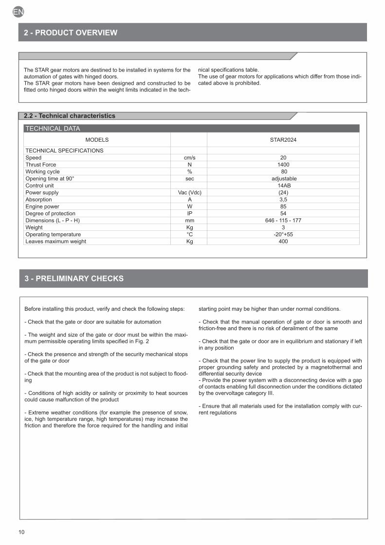
TECHNICAL SPECIFICATIONSSpeed cm/s 20Thrust Force N 1400Working cycle % 80Opening time at 90° sec adjustableControl unit 14ABPower supply Vac (Vdc) (24)Absorption A 3,5Engine power W 85Degree of protection IP 54Dimensions (L - P - H) mm 646 - 115 - 177Weight Kg 3Operating temperature °C -20°+55Leaves maximum weight Kg 400
2 - PRODUCT OVERVIEW
2.1 - Description of the product
The STAR gear motors are destined to be installed in systems for the automation of gates with hinged doors.The STAR gear motors have been designed and constructed to be fitted onto hinged doors within the weight limits indicated in the tech-
nical specifications table.The use of gear motors for applications which differ from those indi-cated above is prohibited.
2.2 - Technical characteristics
3 - PRELIMINARY CHECKS
Before installing this product, verify and check the following steps:
- Check that the gate or door are suitable for automation
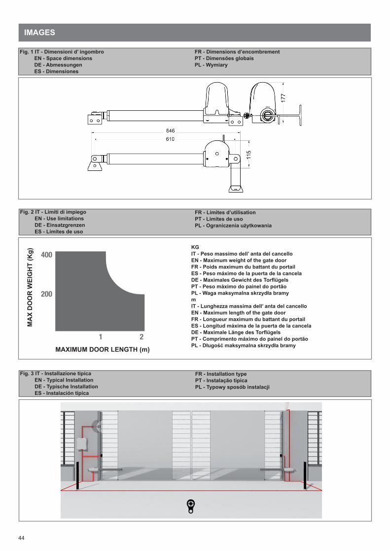
- The weight and size of the gate or door must be within the maxi-mum permissible operating limits specified in Fig. 2
- Check the presence and strength of the security mechanical stops of the gate or door
- Check that the mounting area of the product is not subject to flood-ing
- Conditions of high acidity or salinity or proximity to heat sources could cause malfunction of the product
- Extreme weather conditions (for example the presence of snow, ice, high temperature range, high temperatures) may increase the friction and therefore the force required for the handling and initial
starting point may be higher than under normal conditions.
- Check that the manual operation of gate or door is smooth and friction-free and there is no risk of derailment of the same
- Check that the gate or door are in equilibrium and stationary if left in any position
- Check that the power line to supply the product is equipped with proper grounding safety and protected by a magnetothermal and differential security device- Provide the power system with a disconnecting device with a gap of contacts enabling full disconnection under the conditions dictated by the overvoltage category III.
- Ensure that all materials used for the installation comply with cur-rent regulations
11
EN
4 - PRODUCT INSTALLATION
ù
4.1 - Installation
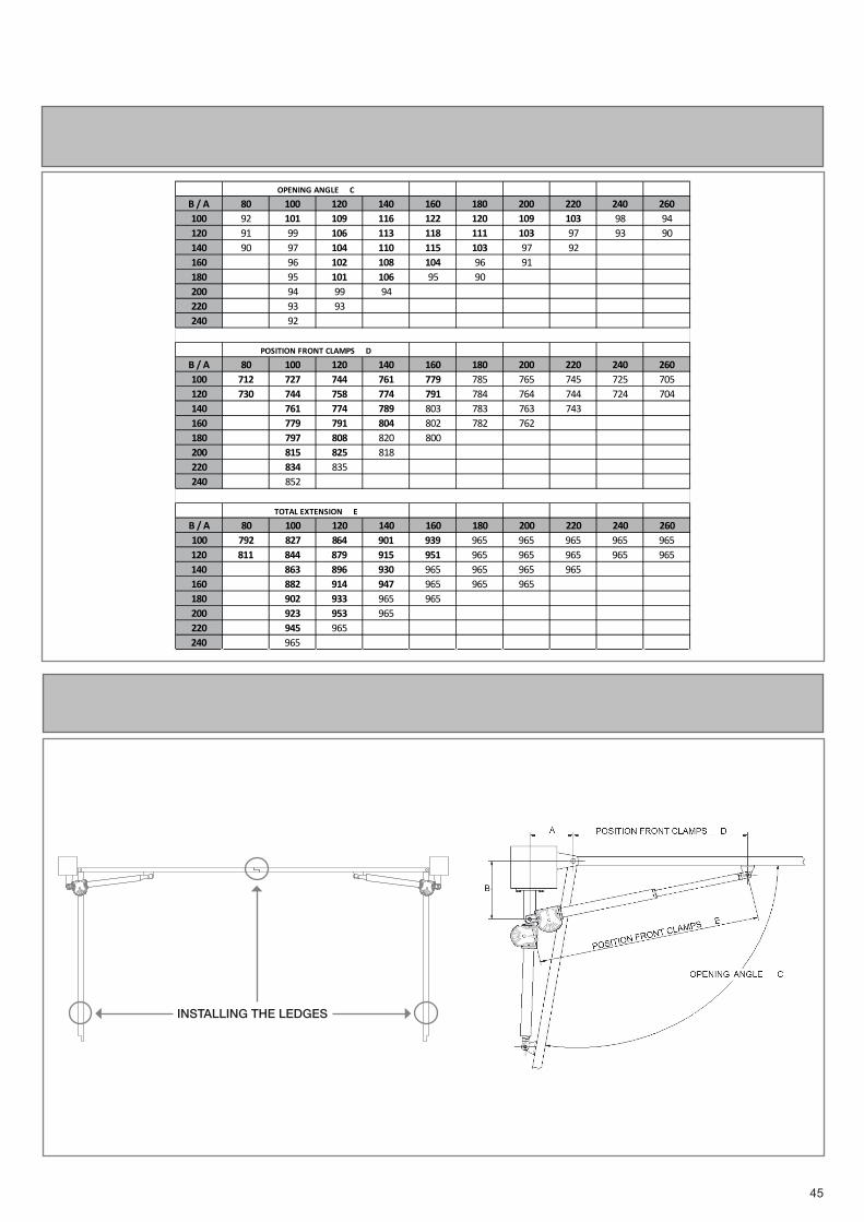
Before proceeding with the installation, check the integrity of the product and that all components are present in the package.Also make sure that the mounting area of the gear motor is compat-ible with the dimensions (Fig.1).Check the permitted opening angle, based on the mounting points of the brackets with the graph (Fig.4).
Fig.3 shows a typical installation:
- Gear motors- Photocells- Columns for photocells- Flashing light with antenna- Key switch or digital keypad- Control unit
Installing the rear fixing bracket
The fixing position of the rear bracket is determined according to the graph (Fig. 4).Important: installations where the values of “A” and “B” (Fig. 5) are as
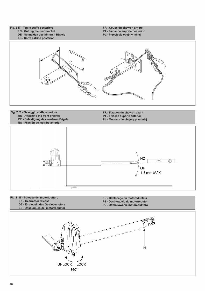
similar to each other as possible are preferred.If necessary, cut the rear bracket (Fig. 6) to obtain the value “B”, then weld the fixing bracket to the wall.Secure the bracket to the wall using welding, screws or bolts (not included).
Installing the front fixing bracket
The front bracket must be fixed to the door according to dimension “E” (Fig.5).
Installing the gear motor
Place the gear motor against the rear bracket and insert the fixing screw.Insert the pin of the sliding bracket into the bush of the front bracket and secure it with the screw and washer provided.Tighten the screw on the rear bracket previously mounted with the nut.
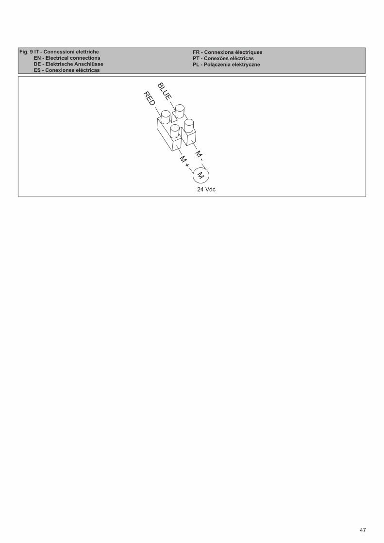
4.2 - Electrical connections
Insert the supply cable to the terminal. Connect the wires of the supply cable to the terminal following the electrical drawing in Fig. 9.
12
EN
5.2 Commissioning
Following the successful testing of all (and not just some) devices in the system you can proceed with the commissioning.
You must prepare, and keep for 10 years, the technical file of the system with the wiring diagram, drawing or photo of the system, risks analysis and solutions adopted, manufacturer declaration of conformity of all devices connected, instruction manual of each de-vice and maintenance schedule of the system.
Fix on the gate or door a plaque indicating the automation data, the name of the person responsible for the commissioning, the serial number and year of construction, the CE mark.
Attach a plaque indicating the steps required to manually unlock the system.
Implement and deliver to the end user the declaration of conform-ity, the instructions and warnings for use for the end user and the maintenance schedule of the system.
Make sure the user understands proper automatic, manual and emergency operation of the automation.
Inform the end user in writing of the dangers and risks still present.
5.1 TestingAll system components must be tested following the procedures outlined in the respective instruction manuals.
Check that they meet the guidelines in Chapter 1 - Safety warningsCheck that the gate or door can move freely once the automation is unlocked, and that they are in equilibrium and stationary if left in any position.
Check the correct operation of all connected devices (photocells, sensitive edges, emergency buttons, etc.), testing the opening, closing and stopping of the gate or door via the connected control devices (transmitters, buttons, switches).
Carry out measurements of the impact force, as prescribed by standard EN12445 adjusting the functions of speed, motor force and deceleration of the unit if the measurements do not give the desired results until you find the right setting.
The testing of the system must be performed by qualified techni-cians who must perform the tests required by relevant legislation related to risks, ensuring compliance with the provisions of the
regulations, in particular the EN12445 standard, which specifies the testing methods for the automation of doors and gates.
5 - TESTING AND COMMISSIONING THE AUTOMATION
13
EN
Key Automation S.r.l. produces systems for the automation of gates, garage doors, automatic doors, shutters, parking lots and road bar-riers. However, Key Automation is not the manufacturer of your au-tomation system, which is rather the result of a process of analysis, evaluation, selection of materials, and installation performed by your own installer. Each automated system is unique and only your installer has the experience and professionalism required to create a system to suit your needs, safe and reliable over time, and carried out in a workmanlike manner, i.e. compliant with the current regula-tions. Even if your automation system meets the security level re-quired by law, this does not exclude the existence of "residual risks", i.e. the possibility that it may cause dangerous situations, usually as a result of improper or irresponsible use; for this reason we would like to give you some suggestions:
• Before using the automation for the first time, ask the installer to explain the origin of residual risks.
• Keep this manual for future use and deliver it to any new owner of the automation.
• Inappropriate or improper use of the automation can make it dan-gerous: do not command the movement of the automation if people, animals or things are in its range.
• Children: If properly designed, an automation system ensures a high degree of security, preventing movement in the presence of people or things with its detection systems, and ensuring always predictable and safe activation. It is prudent to prevent children from playing near the automation and keep remote controls out of their reach to prevent accidental activation.
• Malfunctions: As soon as you notice any malfunctions, disconnect the system from the power supply and operate the manual release. Do not attempt any repairs by yourself, but require the assistance of your installer: meanwhile, the system can operate like a non-au-tomated opening device after releasing the motor reducer with the release key supplied with the system.
• In case of failures or power failures: While awaiting the arrival of your installer or the restore of the electricity, if the system is not equipped with backup batteries, the automation can be operated as any normal non-automated opening device. To do this, you must run the manual release.
Release and manual movement: before performing this operation pay attention that the device can be released only when the door is stationary.
• Maintenance: Like any machine, your automation needs periodic maintenance to ensure its long life and total safety. Agree with your installer on a maintenance plan on a periodic basis; Key Automation recommends a frequency of 6 months for normal domestic use, but this period may vary depending on the intensity of use. All inspec-tion, maintenance or repairs should be performed only by qualified personnel.
• Do not change the system and control or programming parameters of the automation: the responsibility lies with your installer.
• The testing, routine maintenance and any repairs must be docu-mented by the person who performs them, and related documents must kept by the owner.
The only interventions that are possible for the user and should be carried out periodically are the cleaning of the slides and photo-cells, as well as the removal of any leaves or rocks that could hinder the automation. To prevent anyone from activating the gate or door, before proceeding, remember to release the automation and clean only with a cloth slightly dampened with water.
• Disposal: At the end of the automation useful life, make sure that the dismantling is carried out by qualified personnel and the mate-rials are recycled or disposed of according to local regulations in force.
• Operate the gate or door (with remote control, key switch, etc..); if everything is working properly, the gate or the door will open and close normally, otherwise the flashing light flashes and the maneu-ver does not start.
With the safeties out of use, the automation must be repaired as soon as possible.
Replacing the remote control battery: if your remote control seems to work worse or not work at all after a while, this may simply de-pend on the exhaustion of the battery (depending on use, it may take several months to over a year). In that case, you will see that the confirmation of transmission light does not turn on, or comes on only briefly.
The batteries contain polluting substances: do not throw them in the garbage but use the methods prescribed by local regulations.
Thank you for choosing keyautomation; for more information feel free to visit our website www.keyautomation.it.
6 - INSTRUCTIONS AND WARNINGS FOR THE END USER
44
Fig. 2 IT - Limiti di impiego EN - Use limitations DE - Einsatzgrenzen ES - Límites de uso
FR - Limites d’utilisationPT - Limites de usoPL - Ograniczenia użytkowania
Fig. 1 IT - Dimensioni d’ ingombro EN - Space dimensions DE - Abmessungen ES - Dimensiones
FR - Dimensions d’encombrementPT - Dimensões globaisPL - Wymiary
Fig. 3 IT - Installazione tipica EN - Typical Installation DE - Typische Installation ES - Instalación típica
FR - Installation typePT - Instalação típicaPL - Typowy sposób instalacji
IMAGESM
AX
DO
OR
WEI
GH
T (K
g)
MAXIMUM DOOR LENGTH (m)
1 2
400
200
KGIT - Peso massimo dell’ anta del cancelloEN - Maximum weight of the gate doorFR - Poids maximum du battant du portailES - Peso máximo de la puerta de la cancelaDE - Maximales Gewicht des TorflügelsPT - Peso máximo do painel do portãoPL - Waga maksymalna skrzydła bramymIT - Lunghezza massima dell’ anta del cancelloEN - Maximum length of the gate doorFR - Longueur maximum du battant du portailES - Longitud máxima de la puerta de la cancelaDE - Maximale Länge des TorflügelsPT - Comprimento máximo do painel do portão PL - Długość maksymalna skrzydła bramy
45
Fig. 4 IT - Rappresentazione quote EN - Quotes representation DE - Darstellung der Werte ES - Representación cuotas
FR - Représentation hauteursPT - Quotas de representação PL - Przedstawienie wartości
Fig. 5 IT - Grafico angolo di apertura EN - Opening angle graph DE - Zeichnung zum Öffnungswinke ES - Gráfico ángulo de apertura
FR - Graphique angle d’ouverturePT - Gráfico ângulo de abertura PL - Wykres kąta otwarcia
B / A 80 100 120 140 160 180 200 220 240 260
100 92 101 109 116 122 120 109 103 98 94120 91 99 106 113 118 111 103 97 93 90140 90 97 104 110 115 103 97 92160 96 102 108 104 96 91180 95 101 106 95 90200 94 99 94220 93 93240 92
B / A 80 100 120 140 160 180 200 220 240 260
100 712 727 744 761 779 785 765 745 725 705120 730 744 758 774 791 784 764 744 724 704140 761 774 789 803 783 763 743160 779 791 804 802 782 762180 797 808 820 800200 815 825 818220 834 835240 852
B / A 80 100 120 140 160 180 200 220 240 260
100 792 827 864 901 939 965 965 965 965 965120 811 844 879 915 951 965 965 965 965 965140 863 896 930 965 965 965 965160 882 914 947 965 965 965180 902 933 965 965200 923 953 965220 945 965240 965
OPENING ANGLE C
POSITION FRONT CLAMPS D
TOTAL EXTENSION E
INSTALLING THE LEDGES
46
Fig. 7 IT - Fissaggio staffa anteriore EN - Attaching the front bracket DE - Befestigung des vorderen Bügels ES - Fijación del estribo anterior
FR - Fixation du chevron avantPT - Fixação suporte anteriorPL - Mocowanie obejmy przedniej
Fig. 6 IT - Taglio staffa posteriore EN - Cutting the rear bracket DE - Schneiden des hinteren Bügels ES - Corte estribo posterior
FR - Coupe du chevron arrièrePT - Tamanho suporte posteriorPL - Przecięcie obejmy tylnej
Fig. 8 IT - Sblocco del motoriduttore EN - Gearmotor release DE - Entriegeln des Getriebemotors ES - Desbloqueo del motorreductor
FR - Déblocage du motoréducteurPT - Desbloqueio do motorredutorPL - Odblokowanie motoreduktora
NO
OK1-5 mm MAX
H
UNLOCK360°
LOCK
47
Fig. 9 IT - Connessioni elettriche EN - Electrical connections DE - Elektrische Anschlüsse ES - Conexiones eléctricas
FR - Connexions électriquesPT - Conexões eléctricasPL - Połączenia elektryczne
24 Vdc
M +
M -
RE
D
BLU
E
M
48
8 - DECLARATION OF CONFORMITY
DICHIARAZIONE DI INCORPORAZIONE DI QUASI-MACCHINA
DECLARATION OF INCORPORATION OF PARTLY COMPLETED MACHINERY
Key Automation S.r.l. a socio unico
Via A. Volta, 30 Capitale sociale 100.000,00 i.v.
30020 Noventa di Piave (VE) Reg. Imprese di Venezia 03627650264
P.IVA 03627650264 C.F. 03627650264 REA VE 326953
[email protected] www.keyautomation.it
Il sottoscritto Nicola Michelin, Amministratore Delegato dell’azienda
The undersigned Nicola Michelin, General Manager of the company
Key Automation srl, Via Alessandro Volta, 30 - 30020 Noventa di Piave (VE) – ITALIA
dichiara che il prodotto tipo:
declares that the product type:
STAR 24 Motoriduttore elettromeccanico irreversibile 24Vdc a pistone per cancelli battenti
Electromechanical irreversible 24Vdc piston for swing gates
Models:
Models:
900STAR2024, STAR2024DX, STAR2024SX
900PS400-24FA
E’ conforme a quanto previsto dalle seguenti direttive comunitarie:
Is in conformity with the following community (EC) regulations:
Direttiva macchine / Machinery Directive 2006/42/EC
Direttiva compatibilità elettromagnetica / EMC Directive 2004/108/EC
Secondo quanto previsto dalle seguenti norme armonizzate:
In accordance with the following harmonized standards regulations:
EN 55014-1:2006 + A1:2009 + A2:2011
EN 55014-2:1997 + A1:2001 + A2:2008
EN 61000-3-2 + EN 61000-3-3
EN 61000-6-1 + EN 61000-6-2 + EN 61000-6-3 + EN 61000-6-4
EN 62233:2008
Dichiara che la documentazione tecnica pertinente al prodotto è stata redatta conformemente a quanto previsto dalla
direttiva 2006/42/CE Allegato VII parte B e verrà fornita a fronte di una richiesta adeguatamente motivata dalle
autorità nazionali.
Declares that the technical documentation is compiled in accordance with the directive 2006/42/EC Annex VII part B
and will be transmitted in response to a reasoned request by the national authorities.
Dichiara altresì che non è consentita la messa in servizio del prodotto finchè la macchina, in cui il prodotto è
incorporato, non sia stata dichiarata conforme alla direttiva 2006/42/CE.
He also declares that is not allowed to use the above mentioned product until the machine, in which this product is
incorporated, has been identified and declared in conformity with the regulation 2006/42/EC.
Noventa di Piave (VE), 05/08/14
Amministratore Delegato
General Manager Nicola Michelin
DICHIARAZIONE DI INCORPORAZIONE DI QUASI-MACCHINA
DECLARATION OF INCORPORATION OF PARTLY COMPLETED MACHINERY
Key Automation S.r.l. Via A. Volta, 30 Capitale sociale 1.000.000,00 i.v. 30020 Noventa di Piave (VE) Reg. Imprese di Venezia 03627650264 P.IVA 03627650264 C.F. 03627650264 REA VE 326953 [email protected] www.keyautomation.it
Il sottoscritto Nicola Michelin, Amministratore Delegato dell’azienda The undersigned Nicola Michelin, General Manager of the company
Key Automation srl, Via Alessandro Volta, 30 - 30020 Noventa di Piave (VE) – ITALIA dichiara che il prodotto tipo: declares that the product type:
RAY Motoriduttore elettromeccanico a pistone 230Vac o 120Vac per cancelli battenti 230Vac or 120Vac Electromechanical piston for swing gates
Models: Models:
900RAY40, 900RAY40110
E’ conforme a quanto previsto dalle seguenti direttive comunitarie: Is in conformity with the following community (EC) regulations:
Direttiva macchine / Machinery Directive 2006/42/EC Direttiva bassa tensione / Low voltage Directive 2006/95/EC Direttiva compatibilità elettromagnetica / EMC Directive 2004/108/EC
Secondo quanto previsto dalle seguenti norme armonizzate: In accordante with the following harmonized standards regulations:
EN 55014-1:2006 + A1:2009 + A2:2011 EN 55014-2:1997 + A1:2001+ A2:2008 EN 61000-3-2:2006 + A1 + A2:2009 EN 61000-3-3:2008 En 62233:2008
Dichiara che la documentazione tecnica pertinente al prodotto è stata redatta conformemente a quanto previsto dalla direttiva 2006/42/CE Allegato VII parte B e verrà fornita a fronte di una richiesta adeguatamente motivata dalle autorità nazionali. Declares that the technical documentation is compiled in accordance with the directive 2006/42/EC Annex VII part B and will be transmitted in response to a reasoned request by the national authorities. Dichiara altresì che non è consentita la messa in servizio del prodotto finchè la macchina, in cui il prodotto è incorporato, non sia stata dichiarata conforme alla direttiva 2006/42/CE. He also declares that is not allowed to use the above mentioned product until the machine, in which this product is incorporated, has been identified and declared in conformity with the regulation 2006/42/EC.
Noventa di Piave (VE), 12/02/2014 Amministratore Delegato General Manager Nicola Michelin

49
NOTE

50
NOTE

51
NOTE

Key AutomationVia A. Volta 30 - 30020 Noventa di Piave (VE)T. +39 0421.307.456 - F. +39 [email protected] - www.keyautomation.it 580ISSTAR200 REV.02
Instruction version