Embed Size (px)
Citation preview
Conception, fabrication et validation d’une presse à injection basse pression pour le procédé des poudres métalliques
par
Simon G. LAMARRE
MÉMOIRE PRÉSENTÉ À L’ÉCOLE DE TECHNOLOGIE SUPÉRIEURE COMME EXIGENCE PARTIELLEÀ L’OBTENTION DE MAÎTRISE AVEC MÉMOIRE EN GÉNIE MÉCANIQUE
M. Sc. A.
MONTRÉAL, LE 12 DÉCEMBRE 2016
ÉCOLE DE TECHNOLOGIE SUPÉRIEURE UNIVERSITÉ DU QUÉBEC
Simon G. Lamarre, 2016

Cette licence Creative Commons signifie qu’il est permis de diffuser, d’imprimer ou de sauvegarder sur un autre support une partie ou la totalité de cette œuvre à condition de mentionner l’auteur, que ces utilisations soient faites à des fins non commerciales et que le contenu de l’œuvre n’ait pas été modifié.

PRÉSENTATION DU JURY
CE MÉMOIRE A ÉTÉ ÉVALUÉ
PAR UN JURY COMPOSÉ DE : M. Vincent Demers, directeur de mémoire Département de génie mécanique à l’École de technologie supérieure M. Jean-François Chatelain, codirecteur de mémoire Département de génie mécanique à l’École de technologie supérieure M. Pierre Bélanger, président du jury Département de génie mécanique à l’École de technologie supérieure M. Mohammad Jahazi, membre du jury Département de génie mécanique à l’École de technologie supérieure
IL A FAIT L’OBJET D’UNE SOUTENANCE DEVANT JURY ET PUBLIC
LE 7 DÉCEMBRE 2016
À L’ÉCOLE DE TECHNOLOGIE SUPÉRIEURE

REMERCIEMENTS
J’aimerais remercier mes directeurs de mémoire, M. Vincent Demers et M. Jean-François
Châtelain pour leur appui, leur participation active et leur disponibilité pour chacune des
phases de ce projet. J’aimerais mentionner l’apport de Mme Monika Paape-Miyoshi pour la
rédaction de la demande de brevet. Je souhaite également remercier les techniciens de l’École
pour leurs conseils, notamment en usinage, en électronique et en programmation. J’aimerais
de plus souligner l'aide de M. Roch Lamarre pour la révision de la conception de la machine
et les recommandations avisées relatives à l’usinage sur machines conventionnelles.

CONCEPTION, FABRICATION ET VALIDATION D’UNE PRESSE À INJECTION BASSE PRESSION POUR LE PROCÉDÉ DES POUDRES MÉTALLIQUES
Simon G. LAMARRE
RÉSUMÉ
Le moulage par injection à basse pression de poudre métallique est une technique de mise en forme de pièces de formes complexes. La poudre métallique est mélangée avec des polymères basse viscosité (ex. : cire) pour former un mélange homogène à une température supérieure à la température de fusion des polymères. Pour faciliter l’injection dans la cavité du moule, la composition des mélanges est ajustée pour diminuer la viscosité. D’une part, les mélanges peu visqueux possèdent une bonne moulabilité. D’autre part, le phénomène de la ségrégation se manifeste rapidement avec les mélanges peu visqueux. Les machines commerciales sont munies d’un canal d’injection et d’une valve qui relient le réservoir de mélange et la cavité du moule. Le mélange reste stationnaire dans ces composantes entre deux séquences d’injection, ce qui le rend propice à la ségrégation. Plusieurs brevets tentent de résoudre ce problème en utilisant des pompes et des canaux de recirculation. Ces composantes sont difficiles à nettoyer en raison de leur complexité. Une machine à injection basse pression a été conçue et fabriquée pour l’étude de l’aptitude au moulage des mélanges de très faible viscosité (ex. : 0.1 Pa·s), qui tient compte du phénomène de ségrégation et des contraintes de nettoyage. Un piston d’injection puise le volume désiré d’un réservoir. Ensuite, un mouvement latéral cisaille le mélange à l’intersection entre le réservoir et le cylindre et bouche l’orifice de sortie du réservoir. Le cylindre est dégagé et peut recevoir le moule. À la suite de l’injection, le piston retourne à la position du réservoir et entre dans son orifice de sortie. Le mélange résiduel est retourné dans le réservoir, mélangé et désaéré à nouveau. L’appareil a été validé par des essais d’injectabilité avec un mélange de poudre d’acier inoxydable et de liants à basse viscosité. Des essais d’injection ont montré que le mélange contenant l’acide stéarique a parcouru la plus grande distance dans le moule de forme spirale, suivi du mélange contenant l’acide stéarique et l’éthylène vinyle acétate et finalement du mélange contenant seulement la cire de paraffine. Des essais de rhéologie ont corrélé ces résultats pour une viscosité associée à un faible taux de cisaillement. Un essai de ségrégation a montré qu’un temps d’attente de moins d’une minute devait être respecté avant de mesurer une ségrégation importante. De plus, le fonctionnement du système de vacuum a été validé par des analyses radiographiques. Un temps de mélange sous vacuum de 30 min est suffisant pour éliminer complètement la présence de bulles d’air dans la pièce injectée. Mots-clés :
Moulage par injection de poudre; presse à injection; viscosité; ségrégation; aptitude au moulage.

DESIGN, FABRICATION AND VALIDATION OF A LOW PRESSURE INJECTION PRESS FOR METALLIC POWDERS PROCESS
Simon G. LAMARRE
ABSTRACT
Low pressure metal powder injection molding is a forming technique of complex parts. Metal powder is mixed with low viscosity polymers (eg. Wax) to form a homogeneous mixture at a temperature above the polymer melting point temperature. To facilitate injection into the mold cavity, the composition of the mixture is adjusted to decrease the viscosity. On the one hand, the low viscosity feedstocks have good moldability. On the other hand, the phenomenon of segregation rapidly manifest with low viscosity feedstocks. The commercial machines are equipped with an injection channel and a valve which connect the mixing container and the mold cavity. The feedstock remains stationary in these components between two injection sequences, which make it suitable to segregation. Several patents attempt to solve this problem by using pumps and recirculating channels. These components are difficult to clean because of their complexity. A low pressure injection machine has been designed for the study of moldability of very low viscosity feedstocks (0.1 Pa·s) which takes into account the phenomenon of segregation and cleaning constraints. An injection piston withdraws a desired volume of a container. Next, a lateral movement shear the feedstock at the intersection between the container and the cylinder and plug the outlet of the container. The cylinder is then released and can receive the mold. Following the injection, the piston returns to the container position and plug the outlet of the container. The residual mixture is returned to the container, mixed and deaerated again. The device has been validated by injection tests with a mix of stainless steel powder and low viscosity binders. Injection tests have shown that the feedstock containing stearic acid has covers the greatest distance in the spiral shape mold, followed by the feedstock containing stearic acid and ethylene vinyl acetate and finally the feedstock containing only the wax paraffin. Rheological tests were correlated with results for viscosity associated with low shear rates. A segregation test showed that waiting time less than one minute should be respected before measuring a significant segregation. In addition, the operation of the vacuum system has been validated by radiographic analysis. A vacuum under 30 min mixing time is sufficient to completely eliminate the presence of air bubbles in the injected part.
Keywords:
Powder injection molding (PIM); injection press; viscosity; segregation; moldability; feedstock.

TABLE DES MATIÈRES
Page
INTRODUCTION .....................................................................................................................1
CHAPITRE 1 REVUE DE LITTÉRATURE ......................................................................3 1.1 Moulage par injection des poudres ................................................................................3 1.2 Étapes du procédé LPIM ................................................................................................5
1.2.1 Préparation d’un mélange ........................................................................... 6 1.2.2 Injection .................................................................................................... 10 1.2.3 Déliantage ................................................................................................. 12 1.2.4 Frittage ...................................................................................................... 14
1.3 Revue des machines LPIM existantes ..........................................................................14 1.3.1 Fonctionnement général d’une presse LPIM ............................................ 14 1.3.2 Description détaillée des machines existantes .......................................... 16 1.3.3 Difficultés et limites des presses LPIM existantes ................................... 21
1.4 Problématique et objectifs ............................................................................................24
CHAPITRE 2 MÉTHODOLOGIE....................................................................................25 2.1 Méthodologie de conception et de fabrication de la presse .........................................25
2.1.1 Analyse du besoin ..................................................................................... 25 2.1.2 Développement du concept final et essais préliminaires .......................... 26 2.1.3 Conception et fonctionnement du concept de presse à injection
basse pression............................................................................................ 28 2.1.4 Innovation du concept de presse LPIM .................................................... 35
2.2 Méthodologie de validation de la presse ......................................................................36 2.2.1 Choix des ingrédients du mélange ............................................................ 36 2.2.2 Définition des paramètres d’utilisation de la machine .............................. 37 2.2.3 Essais thermogravimétriques .................................................................... 40 2.2.4 Essais d’injection ...................................................................................... 40
CHAPITRE 3 RÉSULTATS .............................................................................................43 3.1 Présentation des résultats des essais préliminaires de validation .................................43
3.1.1 Température du mélange ........................................................................... 43 3.1.2 Lecture de la pression ............................................................................... 44
3.2 Présentation des résultats expérimentaux (article de journal) ......................................45 3.2.1 Introduction ............................................................................................... 47 3.2.2 Experimental procedures .......................................................................... 50
3.2.2.1 Design of an innovative LPIM injection press system .............. 50 3.2.2.2 Materials .................................................................................... 52 3.2.2.3 Specimens processing and measurements ................................. 54
3.2.3 Results ....................................................................................................... 57 3.2.3.1 Minimum vacuum time .............................................................. 57 3.2.3.2 Minimum idle time for low-viscosity feedstocks ...................... 59
XII
3.2.3.3 Viscosity profiles of feedstocks ................................................. 61 3.2.3.4 Injection pressure and injected length ........................................ 63
3.2.4 Discussion ................................................................................................. 65 3.2.5 Conclusions ............................................................................................... 67
CONCLUSION ........................................................................................................................69
ANNEXE I CAHIER DES CHARGES ........................................................................71
ANNEXE II A LOW-PRESSURE POWDER INJECTION MOLDING MACHINE AND METHOD .....................................................................93
ANNEXE III DESSINS D’ASSEMBLAGE ET LISTE DE PIÈCES ...........................139
ANNEXE IV SCHÉMA ÉLECTRIQUE .......................................................................159
ANNEXE V ARTICLE DE CONFÉRENCE MONTREAL’2016 AES-ATEMA ......165
LISTE DE RÉFÉRENCES BIBLIOGRAPHIQUES.............................................................179
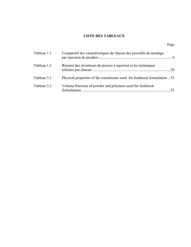
LISTE DES TABLEAUX
Page Tableau 1.1 Comparatif des caractéristiques de chacun des procédés de moulage
par injection de poudres ...............................................................................4
Tableau 1.2 Résumé des inventeurs de presses à injection et les techniques utilisées par chacun ....................................................................................20
Tableau 3.1 Physical properties of the constituents used for feedstock formulation ...53
Tableau 3.2 Volume fractions of powder and polymers used for feedstock formulations ...............................................................................................53

LISTE DES FIGURES
Page
Figure 1.1 Diagramme des variantes du procédé de moulage par injection
de poudres ....................................................................................................4
Figure 1.2 Étapes du procédé PIM ................................................................................6
Figure 1.3 Images d’un lot de poudre d’acier inoxydable prise avec un microscope électrique à balayage montrant des particules rondes (flèches pleines) et des particules irrégulières (flèches hachurées) ...........................................7
Figure 1.4 Exemple de distribution de la taille des particules d’un lot de poudre fournie par Epson Atmix Corp. ....................................................................7
Figure 1.5 La variation de la viscosité en fonction du taux de cisaillement pour les liquides Newtoniens et non-Newtoniens Adapté de Çengel et Cimbala (2006) ............................................................................................8
Figure 1.6 Schématisation du phénomène de détente rapide .....................................11
Figure 1.7 Schématisation des deux types de détentes. a) Détente en phase solide b) Détente conventionnelle .............................................................12
Figure 1.8 Graphique de la température en fonction du temps pour une séquence de déliantage type .......................................................................13
Figure 1.9 Évolution de la densification du matériau pendant le frittage ..................14
Figure 1.10 Schéma d’une machine à injection basse pression ....................................15
Figure 1.11 Schématisation du mouvement de l’outil de mélange dans un (a) mélangeur simple et dans un (b) mélangeur double planétaire ..................16
Figure 1.12 Machine LPIM commerciale Tirée de Peltsman et Peltsman (1983) .......17
Figure 1.13 Schématisation de la forme concave obtenue lors de l’application de la pression Tirée de Yamada et Saito (1998) ................................................18
Figure 1.14 Schéma d’une presse à injection de type pompe foulante Tirée de Nishio et Kawashima (1989) .....................................................................19
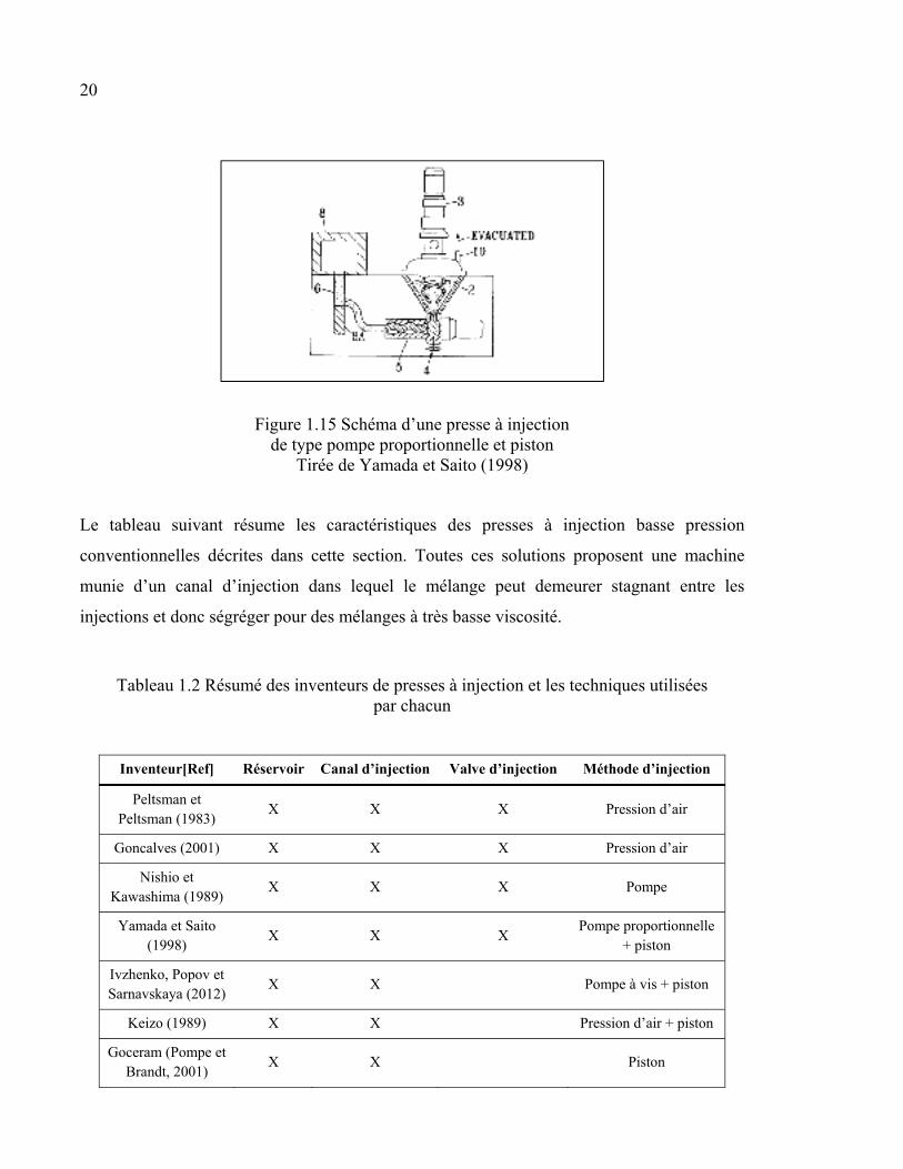
Figure 1.15 Schéma d’une presse à injection de type pompe proportionnelle et piston Tirée de Yamada et Saito (1998).................................................20
XVI
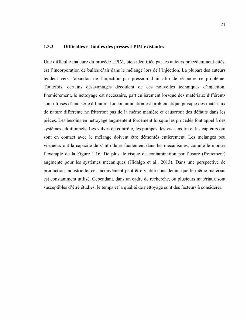
Figure 1.16 Exemple d’infiltration de mélange dans un mécanisme d’une presse à injection qui doit être nettoyé ......................................................22
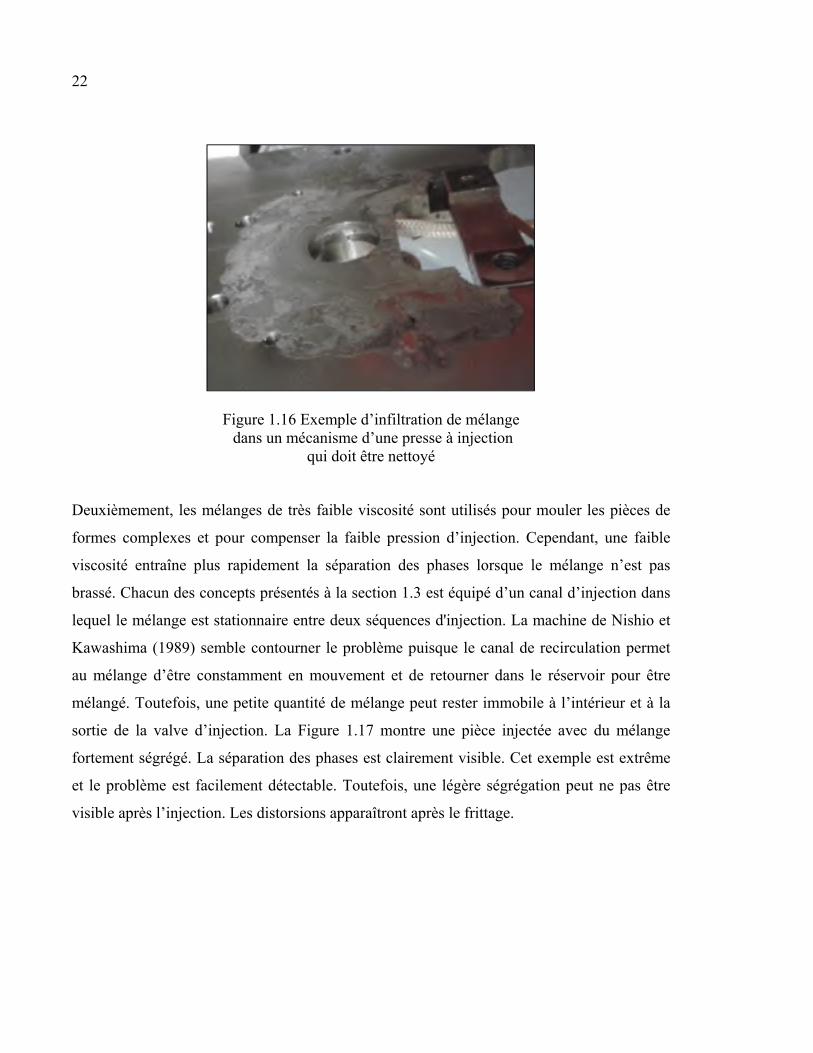
Figure 1.17 Exemple de séparation des phases d’une pièce fortement ségrégée ..........23
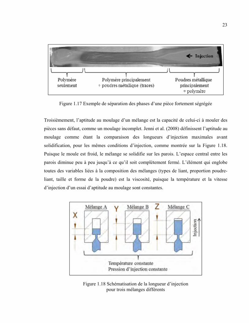
Figure 1.18 Schématisation de la longueur d’injection pour trois mélanges différents ....................................................................................................23
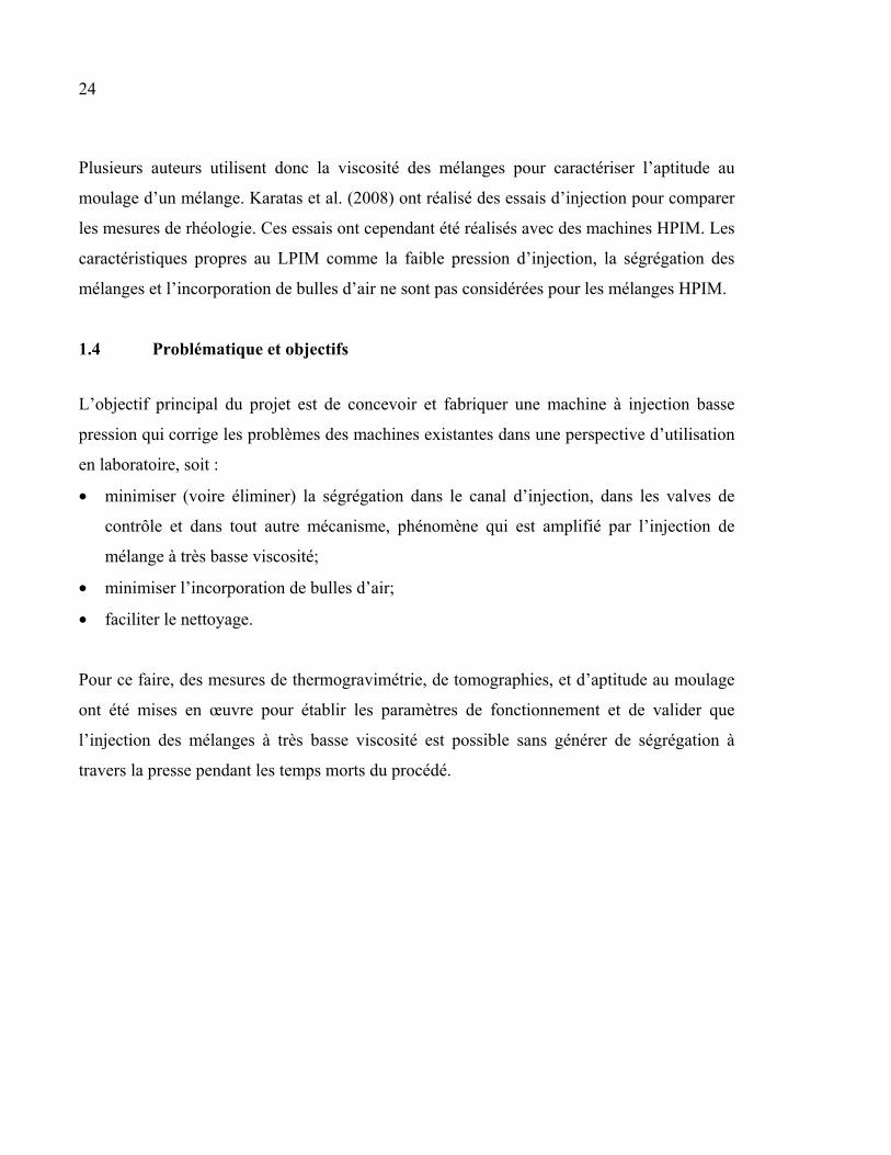
Figure 2.1 Principe de fonctionnement du concept presse (a) Insertion d’une seringue dans un réservoir, (b) ponction d’un volume prédéfini et (c) injection dans une cavité ............................................................................27
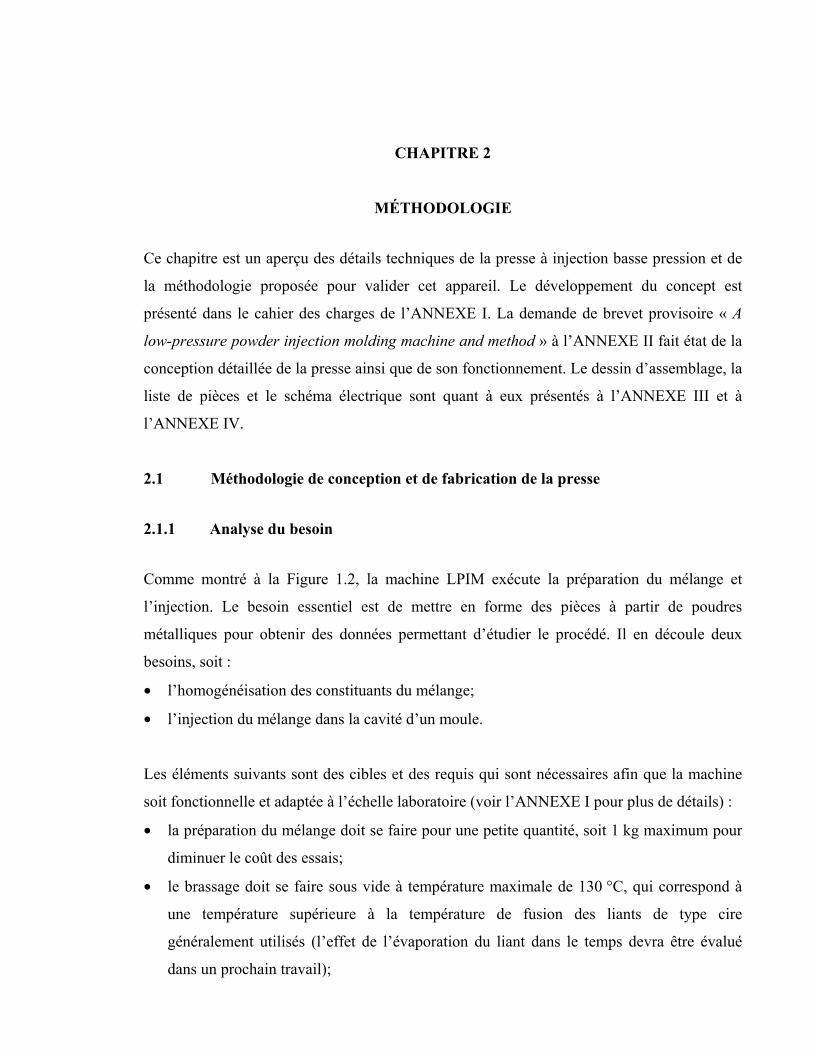
Figure 2.2 (a) Seringue fixée à une table qui puise un volume du réservoir et (b) qui coulisse pour boucher l’ouverture .................................................27
Figure 2.3 Schéma de montage et résultats de l’essai préliminaire de glissement pour un cylindre (a) sans joint torique et (b) avec joint torique .................28
Figure 2.4 Vue générale du concept de presse à injection LPIM ................................29
Figure 2.5 Vue isométrique de la presse à injection et identification des composantes ...............................................................................................30
Figure 2.6 Interface LabVIEW développée ................................................................31
Figure 2.7 (a) Diagramme et (b-c) vues de coupe partielles de la presse à injection qui décrivent la phase de brassage du mélange ..........................33
Figure 2.8 Séquences de la phase d’injection ..............................................................35
Figure 2.9 Démontage du cylindre d’injection ............................................................36
Figure 2.10 Vue de coupe du réservoir montrant la position du thermocouple de lecture de température du réservoir ............................................................38
Figure 2.11 Aspect du mélange dans le réservoir (vue de dessus) pour un vacuum de (a) 1 minute et (b) 40 minutes .................................................39
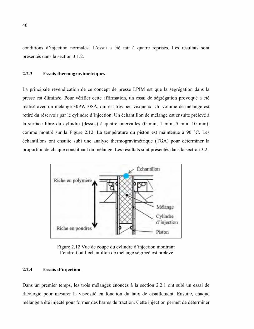
Figure 2.12 Vue de coupe du cylindre d’injection montrant l’endroit où l’échantillon de mélange ségrégé est prélevé .............................................40
Figure 3.1 Température du mélange en fonction de la consigne de température ........43
Figure 3.2 Équation d’ajustement de la consigne de température du réservoir .........44
Figure 3.3 Variation de la lecture de la pression résultante du frottement du joint torique sur la paroi du cylindre d’injection ................................................45
XVII
Figure 3.4 General view of the injection system in a mold alignment position, and (b-g) partial section views of the injection system describing the method for injecting a feedstock. ...............................................................52
Figure 3.5 SEM micrograph of 316L powder .............................................................54
Figure 3.6 Mold design and injected specimen: (a) Rectangular dogbone shape, (b) spiral shape (dimensions in millimeters) ..............................................55
Figure 3.7 Typical TGA curves ...................................................................................57
Figure 3.8 X-ray scan and CT scan radiographies: (a) X-ray scan images of the injected specimens for vacuum time period of 1, 15, 30, and 45 minutes; (b) CT scan images in a zone containing several air bubbles; (c) CT scan images in a zone containing no air bubbles ............59
Figure 3.9 Evolution of solid loading according to time spent in molten state (feedstock 30PW-10SA) ............................................................................61
Figure 3.10 Viscosity profiles of feedstocks at 90°C ....................................................62
Figure 3.11 Evolution of the pressure during the stroke-controlled injection of (a) rectangular specimens, and (b) spiral specimens .......................................64
Figure 3.12 Injected length of (a) rectangular specimens, and (b) spiral specimens ....65
Figure 3.13 Comparison of the injected length, piston position, injection pressure, and viscosity...............................................................................................67

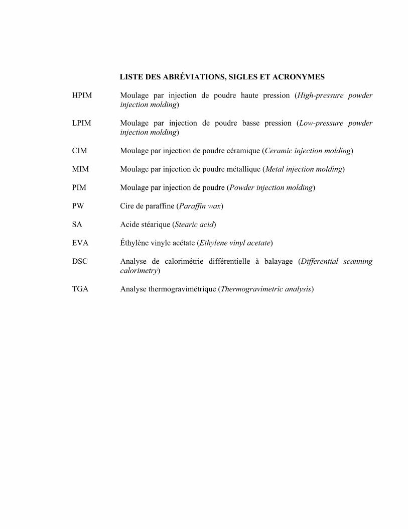
LISTE DES ABRÉVIATIONS, SIGLES ET ACRONYMES HPIM Moulage par injection de poudre haute pression (High-pressure powder
injection molding) LPIM Moulage par injection de poudre basse pression (Low-pressure powder
injection molding) CIM Moulage par injection de poudre céramique (Ceramic injection molding) MIM Moulage par injection de poudre métallique (Metal injection molding) PIM Moulage par injection de poudre (Powder injection molding) PW Cire de paraffine (Paraffin wax) SA Acide stéarique (Stearic acid) EVA Éthylène vinyle acétate (Ethylene vinyl acetate) DSC Analyse de calorimétrie différentielle à balayage (Differential scanning
calorimetry) TGA Analyse thermogravimétrique (Thermogravimetric analysis)

LISTE DES SYMBOLES ET UNITÉS DE MESURE mm millimètre (unité de distance) µm micromètre (unité de distance) l litre (unité de volume) ml millilitre (unité de volume) mm³ millimètre cube (unité de volume) s seconde (unité de temps) min minute (unité de temps) kg kilogramme (unité de masse) ° degré (unité d’angle) MPa méga Pascal (unité de pression) mm de Hg millimètre de mercure (unité de pression) Pa∙s Pascal seconde (unité de la viscosité) s-1 seconde moins un (unité du taux de cisaillement) °C degré Celsius (unité de température) N Newton (unité de force) mm/s millimètre par seconde (unité de vitesse) rpm rotation par minute (unité de vitesse de rotation) kV kilovolt (unité de tension électrique) µA microampère (unité du courant électrique)

INTRODUCTION
Le moulage par injection de poudres métalliques (PIM) est un procédé de mise en forme
convenant aux petites pièces de formes complexes. Un mélange de poudres métalliques en
phase solide et de liant chaud en phase liquide est injecté dans la cavité d’un moule. La pièce
moulée est ensuite déliantée pour retirer le liant et est frittée pour être densifiée. Ce procédé
permet de fabriquer des pièces dont la forme est quasi-finale et qui est bien adapté à la mise
en forme des matériaux difficiles à usiner par des méthodes conventionnelles. Le moulage
par injection basse pression de poudres métalliques (LPIM) gagne en popularité par rapport
au moulage par injection haute pression de poudres métalliques (HPIM) en raison de son
équipement léger, moins coûteux et de la demande pour la mise en forme de pièces de formes
complexes à faible coût.
Afin de réaliser l’injection à faible pression, les mélanges typiques LPIM sont composés de
liants à basse viscosité. Cette propriété rend toutefois les mélanges propices à la ségrégation,
soit la séparation des phases solide et liquide. La ségrégation est responsable de la densité
non uniforme des pièces moulées. Un compromis doit donc être fait en augmentant la
viscosité, afin d’assurer un moulage complet de densité uniforme. Des courbes de rhéologie,
qui tracent l'évolution de la viscosité en fonction du taux de cisaillement induit au mélange,
servent à caractériser l’aptitude au moulage des différents mélanges.
Le développement et la production de nouveaux mélanges font face à un dilemme. La
viscosité des mélanges est diminuée pour augmenter l’aptitude au moulage, alors que la
viscosité doit être augmentée pour diminuer la ségrégation. Le développement d’une
corrélation entre la phase d’injection et les mesures de rhéologie s’avère donc difficile à
définir avec les machines existantes en raison du phénomène de ségrégation. En effet, le
mélange est propice à la ségrégation dans le canal d’injection des machines existantes entre
deux séquences d’injection, ce qui peut modifier le comportement des mélanges.
2
L’objectif de ce projet est de concevoir, fabriquer et valider une machine à injection basse
pression de poudres métalliques pour une utilisation en laboratoire qui élimine le phénomène
de ségrégation dans le canal d’injection. Un cahier des charges permettra de définir en détail
les besoins et les requis pour la génération de concepts préliminaires ainsi que pour la
conception détaillée. La machine conçue sera fabriquée et assemblée dans les locaux de
l’ÉTS. La validation de la machine se fera par des essais d’injection de différents mélanges
pour montrer que des mesures de rhéologie (viscosité) peuvent servir à caractériser l’aptitude
au moulage d’un mélange.
Les essais réalisés dans le cadre de cette recherche sont limités aux mélanges de poudres
métalliques et de liant à base de cire de paraffine, d’acide stéarique et d’éthylène vinyle
acétate. Des études subséquentes pourront être réalisées pour étendre les capacités de la
machine aux autres types de mélange, entre autres à base de poudres de céramiques.
Ce mémoire propose une revue de littérature générale du procédé de moulage par injection,
avec un accent sur les particularités de l’injection à basse pression. Ensuite, le
fonctionnement d’une machine typique LPIM est décrit ainsi que plusieurs de ses variantes.
La méthodologie et la presse à injection basse pression développée sont présentées. Ensuite,
les résultats d’injection sont comparés à des mesures de rhéologie afin de valider le
fonctionnement de la presse dans le but d’étudier l’aptitude au moulage des mélanges de très
faible viscosité. Des essais seront aussi réalisés pour montrer la capacité de la machine à
minimiser la ségrégation des mélanges peu visqueux. Ces éléments sont entre autres
présentés dans un article de journal soumis ainsi que dans un article de conférence présenté et
une demande de brevet provisoire.
CHAPITRE 1
REVUE DE LITTÉRATURE
1.1 Moulage par injection des poudres
L’intérêt envers les poudres de céramiques a connu un essor important dans les années 1970
pour répondre aux demandes grandissantes quant à la résistance des matériaux, notamment
par l’industrie aéronautique (Mangels, 1994). Les procédés de mise en forme offerts à
l’époque comme la coulée en barbotine (splip casting) et le pressage isostatique nécessitent
des opérations secondaires de finition, qui engendrent des coûts supplémentaires
(Medvedovski et Peltsman, 2012). Parallèlement, le procédé de moulage par injection de
plastique s’est développé rapidement où du plastique fondu est injecté à haute pression dans
la cavité d’un moule pour former des pièces de forme complexe proches de leurs dimensions
finales. Cette technique a été ajustée pour un mélange composé de poudres de céramique
(CIM) et de polymères, qui sert de liant. Éventuellement, les mélanges à base de poudres
métalliques (MIM) ont aussi été utilisés.
Les avantages du procédé PIM sont nombreux, soit :
• l’absence ou le peu d’opérations secondaires de finition;
• la grande variété de matériaux offerts, tant pour les poudres de céramique que pour les
poudres métalliques;
• la capacité pour des volumes de production élevés;
• les propriétés mécaniques élevées (généralement supérieures au procédé de fonderie,
mais inférieures au procédé de corroyage (Heaney, 2012a)).
Toutefois, les poudres de céramiques sont très abrasives. La haute pression atteinte durant
l’injection endommage rapidement l’outillage. Peltsman (1986) a alors développé un procédé
de moulage par injection à basse pression (LPIM), qui est distinct du procédé de moulage par
4
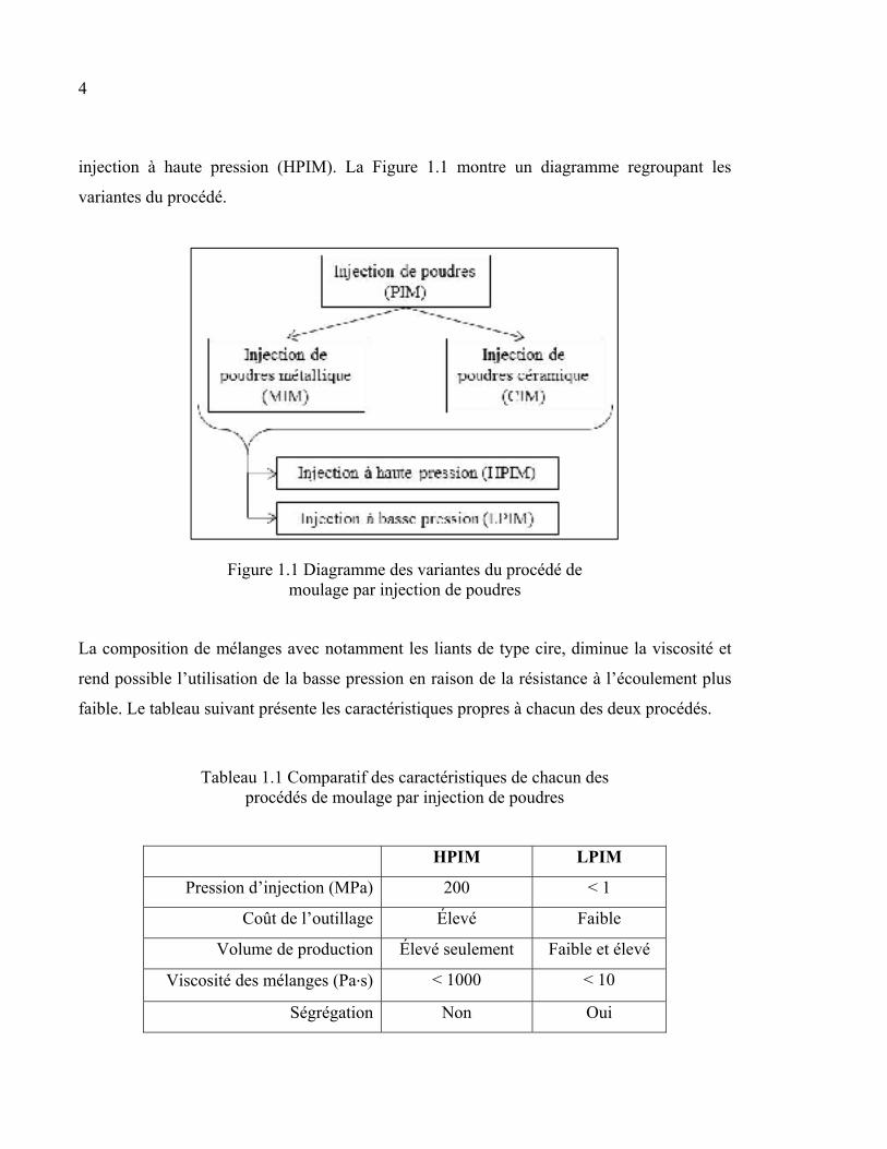
injection à haute pression (HPIM). La Figure 1.1 montre un diagramme regroupant les
variantes du procédé.
Figure 1.1 Diagramme des variantes du procédé de moulage par injection de poudres
La composition de mélanges avec notamment les liants de type cire, diminue la viscosité et
rend possible l’utilisation de la basse pression en raison de la résistance à l’écoulement plus
faible. Le tableau suivant présente les caractéristiques propres à chacun des deux procédés.
Tableau 1.1 Comparatif des caractéristiques de chacun des procédés de moulage par injection de poudres
HPIM LPIM
Pression d’injection (MPa) 200 < 1
Coût de l’outillage Élevé Faible
Volume de production Élevé seulement Faible et élevé
Viscosité des mélanges (Pa∙s) < 1000 < 10
Ségrégation Non Oui
5
Le marché des pièces produites selon le procédé d’injection de poudres (HPIM) est assez
étendu, notamment aux domaines de l’électronique, de l’aéronautique et de l’automobile. Les
composantes comme des dissipateurs de chaleur et des turbines de turbocompresseur peuvent
être produites selon le procédé HPIM (Lee, Seong Jin et German, 2011). La mise en forme
d’outils de coupe a recours au procédé HPIM. Puisque ces outils servent à usiner d’autres
matériaux, ils doivent avoir une dureté et une résistance à l’usure importante. Ces outils de
coupe sont alors difficiles à mettre en forme par des méthodes conventionnelles.
La conception des pièces produites par PIM suit certaines recommandations :
• les sections très volumineuses sont à éviter, tandis que les sections de mur constantes sont
recommandées afin d’éviter le rétrécissement non uniforme de la pièce (Heaney, 2012a);
• l’épaisseur des pièces typiques se situe entre 2 et 50 mm (Kryachek, 2004);
• les angles de démoulage de 2° sont suggérés pour faciliter l’expulsion du moule;
• la pièce devrait inclure une surface plane afin d’asseoir la pièce correctement lors des
étapes suivant le démoulage (Heaney, 2012a);
• les valeurs typiques de tolérances obtenues entre chaque pièce sont de l’ordre de ± 0,3 %
de la dimension mesurée (Vervoort, Vetter et Duszczyk, 1996);
• le fini de surface obtenu est de 2,5 à 5 µm.
La suite de ce mémoire fera référence au procédé de moulage par injection à basse pression
de poudres métalliques (LPIM), bien que certaines notions soient valables pour le CIM et le
HPIM.
1.2 Étapes du procédé LPIM
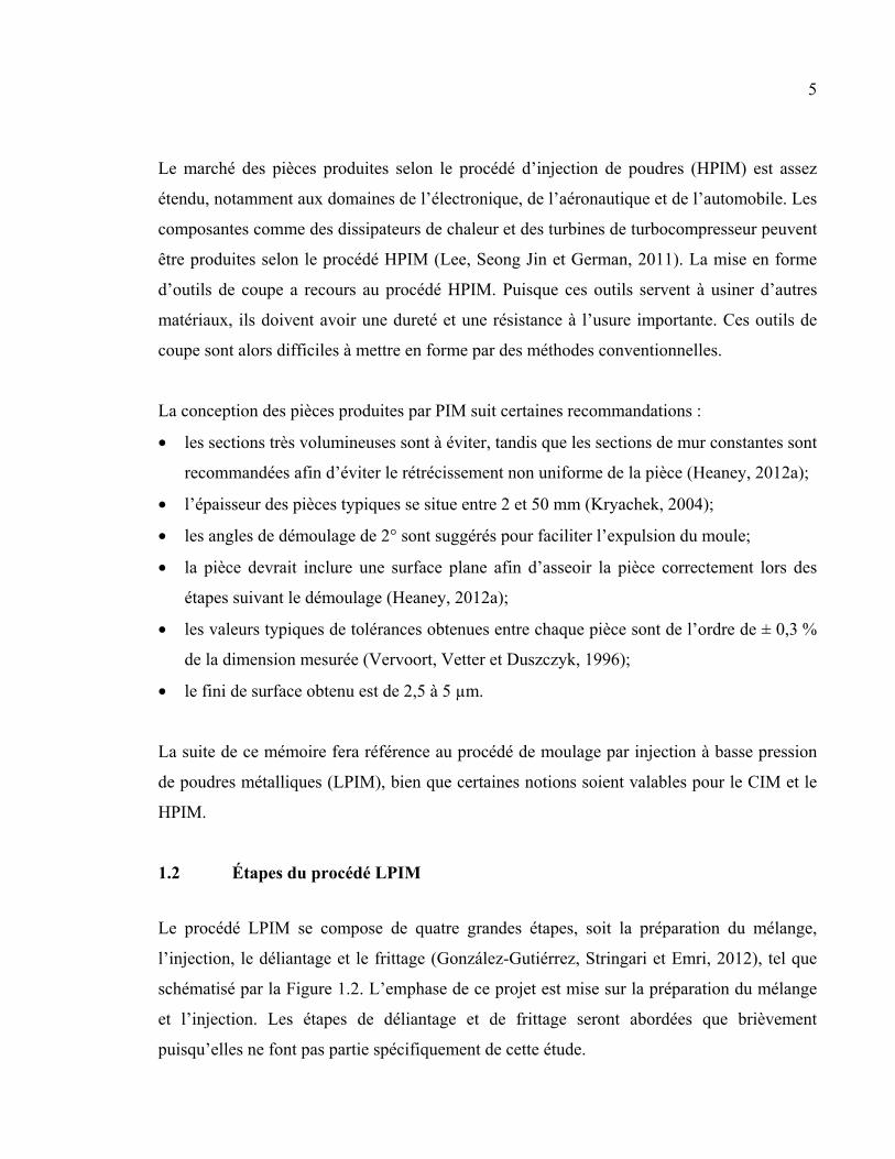
Le procédé LPIM se compose de quatre grandes étapes, soit la préparation du mélange,
l’injection, le déliantage et le frittage (González-Gutiérrez, Stringari et Emri, 2012), tel que
schématisé par la Figure 1.2. L’emphase de ce projet est mise sur la préparation du mélange
et l’injection. Les étapes de déliantage et de frittage seront abordées que brièvement
puisqu’elles ne font pas partie spécifiquement de cette étude.
6
Figure 1.2 Étapes du procédé PIM
1.2.1 Préparation d’un mélange
La préparation d'un mélange consiste à brasser des quantités précises de poudres métalliques
et de liant. La poudre métallique se caractérise par sa forme et sa taille. La forme sphérique et
la forme irrégulière, produites par le procédé d’atomisation, sont les plus répandues. La
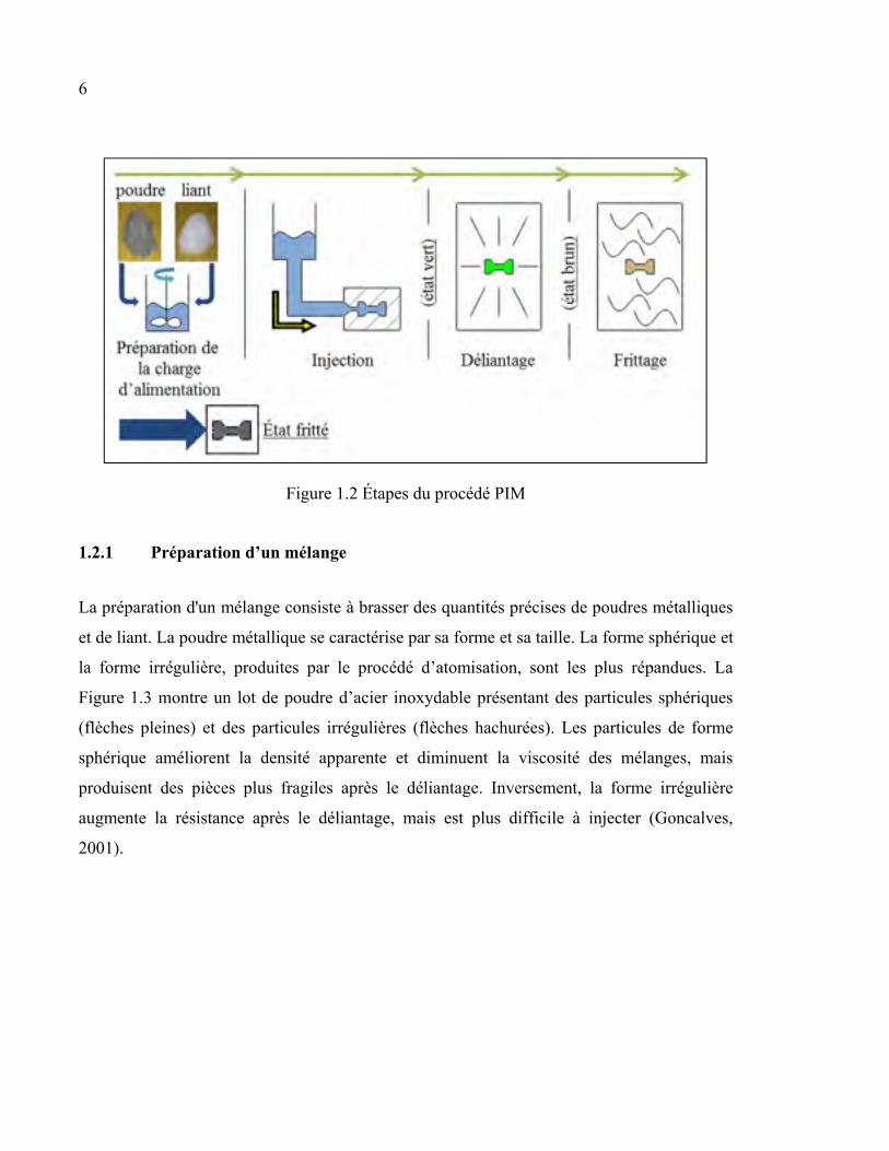
Figure 1.3 montre un lot de poudre d’acier inoxydable présentant des particules sphériques
(flèches pleines) et des particules irrégulières (flèches hachurées). Les particules de forme
sphérique améliorent la densité apparente et diminuent la viscosité des mélanges, mais
produisent des pièces plus fragiles après le déliantage. Inversement, la forme irrégulière
augmente la résistance après le déliantage, mais est plus difficile à injecter (Goncalves,
2001).
7
Figure 1.3 Images d’un lot de poudre d’acier inoxydable prise avec un microscope électrique à balayage montrant des particules
rondes (flèches pleines) et des particules irrégulières (flèches hachurées)
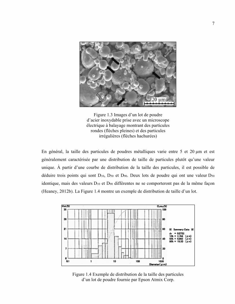
En général, la taille des particules de poudres métalliques varie entre 5 et 20 µm et est
généralement caractérisée par une distribution de taille de particules plutôt qu’une valeur
unique. À partir d’une courbe de distribution de la taille des particules, il est possible de
déduire trois points qui sont D10, D50 et D90. Deux lots de poudre qui ont une valeur D50
identique, mais des valeurs D10 et D90 différentes ne se comporteront pas de la même façon
(Heaney, 2012b). La Figure 1.4 montre un exemple de distribution de taille d’un lot.
Figure 1.4 Exemple de distribution de la taille des particules d’un lot de poudre fournie par Epson Atmix Corp.
8
Le liant a deux fonctions dans le procédé d’injection LPIM, selon son état. Lorsqu’il est en
phase liquide, il sert de médium de transport en facilitant le déplacement de la poudre dans la
cavité d’injection. Lorsqu’il est en phase solide, il sert à lier les particules de poudre les unes
aux autres afin de maintenir la forme donnée par le moule jusqu’à l’étape de déliantage
(Vervoort, Vetter et Duszczyk, 1996). La caractéristique clé du liant est sa viscosité. Plus la
viscosité est basse, moins de force doit être appliquée pour cisailler le liant, ce qui facilite
l’injection. Les liants utilisés comme matériau primaire pour le LPIM sont de la famille des
thermoplastiques comme la cire de paraffine, la cire d’abeille et la cire de Carnauba. Les
cires ont une viscosité très faible (< 0,1 Pa∙s) et ont un bon effet mouillant et lubrifiant. De
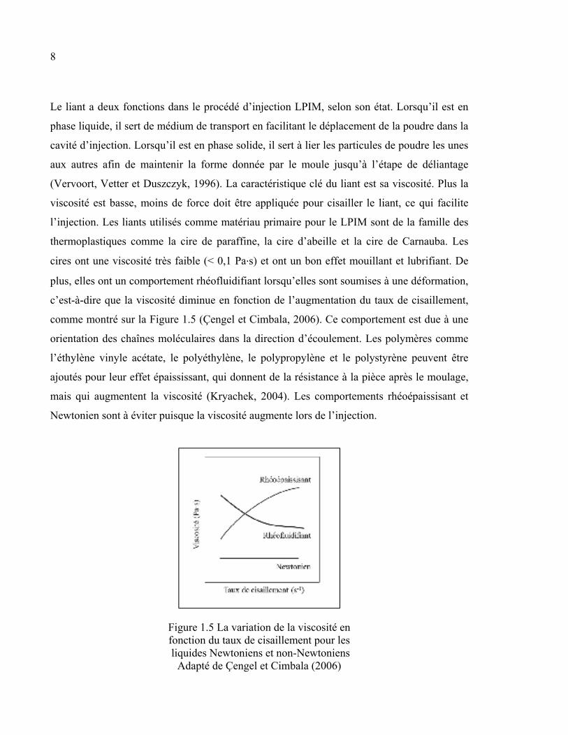
plus, elles ont un comportement rhéofluidifiant lorsqu’elles sont soumises à une déformation,
c’est-à-dire que la viscosité diminue en fonction de l’augmentation du taux de cisaillement,
comme montré sur la Figure 1.5 (Çengel et Cimbala, 2006). Ce comportement est due à une
orientation des chaînes moléculaires dans la direction d’écoulement. Les polymères comme
l’éthylène vinyle acétate, le polyéthylène, le polypropylène et le polystyrène peuvent être
ajoutés pour leur effet épaississant, qui donnent de la résistance à la pièce après le moulage,
mais qui augmentent la viscosité (Kryachek, 2004). Les comportements rhéoépaissisant et
Newtonien sont à éviter puisque la viscosité augmente lors de l’injection.
Figure 1.5 La variation de la viscosité en fonction du taux de cisaillement pour les liquides Newtoniens et non-Newtoniens
Adapté de Çengel et Cimbala (2006)
9
La mouillabilité des particules de poudre est un facteur important et l’ajout de surfactants
comme l’acide stéarique (SA) permet de réduire la tension de surface et de faciliter
l’incorporation du liant entre les particules de poudres. Par contre, cette propriété rend le
mélange propice à la ségrégation qui peut être généralement contrôlé par l’ajout d’agents
épaississants (Ahn et al., 2009). La viscosité est aussi affectée par la distribution de taille de
la poudre. Une distribution de taille plus étendue diminue la viscosité, puisque les particules
plus fines comblent l’espace entre les particules plus grossière. De plus, les particules plus
grossières diminuent la surface à recouvrir, ce qui rend disponible plus de liant aux autres
particules.
La viscosité et l’homogénéité du mélange de poudre et de liant sont définies par la fraction
volumique, la température et le temps et la vitesse de brassage. La fraction volumique
représente la proportion de poudres métalliques et la proportion de liant, mesurées en
pourcentage volumique des constituants. Selon German et Bose (1997), la proportion
volumique de poudre se situe généralement entre 50 % et 70 % du volume total du mélange.
Une proportion inférieure à 50 % nuit au déliantage dû à la faible densité de la pièce (peu de
contact entre les particules de poudres), tandis qu’une proportion trop élevée rend difficile
(voire impossible) l’injection due à la viscosité trop élevée. Aussi, Kryachek (2004)
recommande d’utiliser un minimum de liant afin de diminuer le temps de déliantage et de
minimiser le rétrécissement. Bien qu’une grande quantité de liant facilite l’injection, les
forces appliquées au mélange pour le déplacer peuvent générer de la ségrégation dynamique
(Medvedovski et Peltsman, 2012). Ce type de ségrégation est associé à des vitesses
d’injection rapide. La ségrégation statique est la plus évidente pour les mélanges très peu
visqueux. Elle correspond en fait à une séparation des phases solides et liquides au repos.
Cette séparation est due à la gravité. Les particules métalliques étant plus lourdes, elles
s’accumulent vers le bas.
Selon González-Gutiérrez, Stringari et Emri (2012), la ségrégation mène à des défauts
comme de la porosité, du gauchissement et des fissures. Ces défauts sont dus à un
rétrécissement non isotrope de la pièce.
10
La température du mélange a une influence sur la viscosité (Hausnerova et al., 2005). La
viscosité des liquides diminue à température élevée, car les molécules de liant ont plus
d’énergie, ce qui leur permet de bouger librement (Çengel et Cimbala, 2006). Le temps et la
vitesse de brassage contrôlent l’homogénéité du mélange. Le mélangeur brise les amas de
poudres pour que le liant englobe bien les particules de poudres. Les zones à forte
concentration de liant causent des vides lors du frittage tandis que les amas de poudres
peuvent s’effondrer entre la sortie du moule et l’opération de frittage. Aussi, une vitesse de
brassage trop élevée introduit des bulles d’air dans le mélange, qui causeront par la suite des
vides dans la pièce frittée. Elle peut aussi causer de la ségrégation due à l’inertie.
Le contrôle de la température du mélange permet d’obtenir et de maintenir une certaine
viscosité sans détériorer le liant. Le brassage se fait sous vide pour retirer les bulles d’air
dans le mélange. Les bulles d’air laissent des vides internes qui affaiblissent la pièce frittée.
La qualité d’un mélange, soit la validation de la fraction volumique, est mesurée par
l’analyse thermogravimétrique (TGA) (Sack et Lietzmann, 1990). Cette mesure permet de
déterminer la proportion massique de chaque constituant présent dans l’échantillon.
1.2.2 Injection
L’injection consiste à remplir la cavité d’un moule avec un mélange de poudre et de liant
fondu. Cette opération se fait en contrôlant certains paramètres, dont la pression, la
température, la vitesse du mélange et le temps d’injection. Une pression est appliquée au
mélange pour le déplacer. Cette pression qu’il faut appliquer sur le mélange est le résultat de
la résistance interne à l’écoulement, qui est causée par les forces de cohésion entre les
particules dans le mélange (Çengel et Cimbala, 2006). La viscosité est la mesure de cette
résistance à l’écoulement. La pression est le résultat des forces de frottement sur les parois de
la machine et aux pertes de charge. Celles-ci sont entre autres dues aux changements de
direction dans les canaux d’injection, à la forme du moule et à la présence de capteurs dans
l’écoulement.
11
Comme montrée à la section précédente, la température du mélange a une influence sur la
viscosité. Elle doit être constante en tout temps dans chaque section de la machine afin
d’assurer une constance dans le processus d’injection. La température du moule est inférieure
à la température du mélange et permet donc de refroidir et solidifier les pièces moulées. Un
moule trop froid peut causer des lignes de joints ou un moulage incomplet, puisque le
mélange se solidifie trop rapidement dans le moule (Schlieper, 2012).
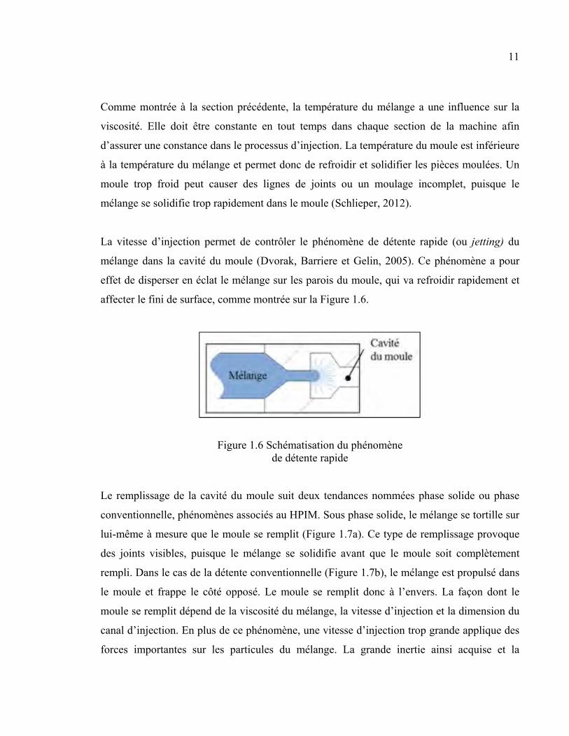
La vitesse d’injection permet de contrôler le phénomène de détente rapide (ou jetting) du
mélange dans la cavité du moule (Dvorak, Barriere et Gelin, 2005). Ce phénomène a pour
effet de disperser en éclat le mélange sur les parois du moule, qui va refroidir rapidement et
affecter le fini de surface, comme montrée sur la Figure 1.6.
Figure 1.6 Schématisation du phénomène de détente rapide
Le remplissage de la cavité du moule suit deux tendances nommées phase solide ou phase
conventionnelle, phénomènes associés au HPIM. Sous phase solide, le mélange se tortille sur
lui-même à mesure que le moule se remplit (Figure 1.7a). Ce type de remplissage provoque
des joints visibles, puisque le mélange se solidifie avant que le moule soit complètement
rempli. Dans le cas de la détente conventionnelle (Figure 1.7b), le mélange est propulsé dans
le moule et frappe le côté opposé. Le moule se remplit donc à l’envers. La façon dont le
moule se remplit dépend de la viscosité du mélange, la vitesse d’injection et la dimension du
canal d’injection. En plus de ce phénomène, une vitesse d’injection trop grande applique des
forces importantes sur les particules du mélange. La grande inertie ainsi acquise et la
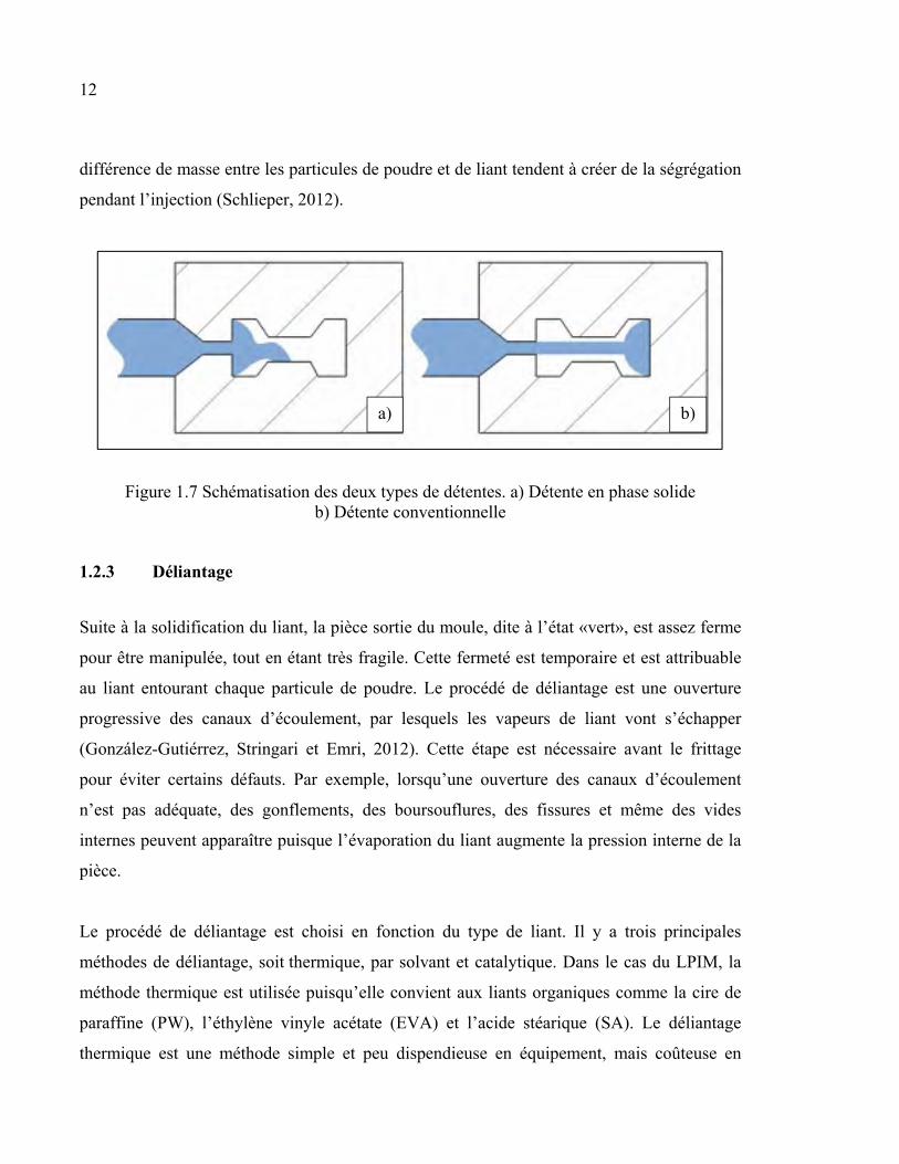
12
différence de masse entre les particules de poudre et de liant tendent à créer de la ségrégation
pendant l’injection (Schlieper, 2012).
Figure 1.7 Schématisation des deux types de détentes. a) Détente en phase solide b) Détente conventionnelle
1.2.3 Déliantage
Suite à la solidification du liant, la pièce sortie du moule, dite à l’état «vert», est assez ferme
pour être manipulée, tout en étant très fragile. Cette fermeté est temporaire et est attribuable
au liant entourant chaque particule de poudre. Le procédé de déliantage est une ouverture
progressive des canaux d’écoulement, par lesquels les vapeurs de liant vont s’échapper
(González-Gutiérrez, Stringari et Emri, 2012). Cette étape est nécessaire avant le frittage
pour éviter certains défauts. Par exemple, lorsqu’une ouverture des canaux d’écoulement
n’est pas adéquate, des gonflements, des boursouflures, des fissures et même des vides
internes peuvent apparaître puisque l’évaporation du liant augmente la pression interne de la
pièce.
Le procédé de déliantage est choisi en fonction du type de liant. Il y a trois principales
méthodes de déliantage, soit thermique, par solvant et catalytique. Dans le cas du LPIM, la
méthode thermique est utilisée puisqu’elle convient aux liants organiques comme la cire de
paraffine (PW), l’éthylène vinyle acétate (EVA) et l’acide stéarique (SA). Le déliantage
thermique est une méthode simple et peu dispendieuse en équipement, mais coûteuse en
a) b)
13
temps, qui se base sur la dissociation des molécules de polymère en molécules plus simples
qui seront ensuite évaporées. Les pièces sont placées dans un four dont l’augmentation de
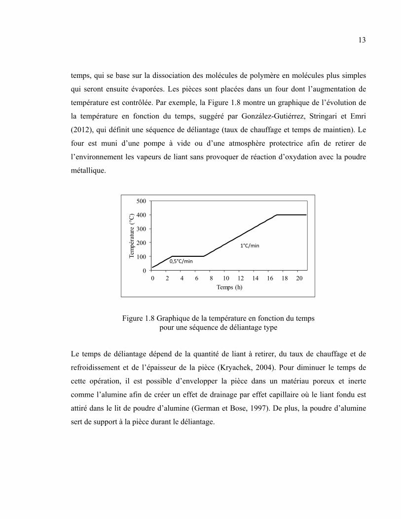
température est contrôlée. Par exemple, la Figure 1.8 montre un graphique de l’évolution de
la température en fonction du temps, suggéré par González-Gutiérrez, Stringari et Emri
(2012), qui définit une séquence de déliantage (taux de chauffage et temps de maintien). Le
four est muni d’une pompe à vide ou d’une atmosphère protectrice afin de retirer de
l’environnement les vapeurs de liant sans provoquer de réaction d’oxydation avec la poudre
métallique.
Figure 1.8 Graphique de la température en fonction du temps pour une séquence de déliantage type
Le temps de déliantage dépend de la quantité de liant à retirer, du taux de chauffage et de
refroidissement et de l’épaisseur de la pièce (Kryachek, 2004). Pour diminuer le temps de
cette opération, il est possible d’envelopper la pièce dans un matériau poreux et inerte
comme l’alumine afin de créer un effet de drainage par effet capillaire où le liant fondu est
attiré dans le lit de poudre d’alumine (German et Bose, 1997). De plus, la poudre d’alumine
sert de support à la pièce durant le déliantage.
0
100
200
300
400
500
0 2 4 6 8 10 12 14 16 18 20
Tem
péra
ture
(°C
)
Temps (h)
1°C/min
0,5°C/min
14
1.2.4 Frittage
La densification finale de la pièce a lieu lors du frittage. Les pièces déliées, à l’état «brun»,
sont placées dans un four sous atmosphère contrôlée pour subir une densification (German et
Bose, 1997). Elle se produit par l’élimination des pores (espaces entre les particules) qui est
due au mouvement de masse. Il y a quatre mécanismes de mouvement de la masse, soit la
diffusion de surface, la diffusion aux joints de particule, la diffusion de volume et
l’évaporation et la condensation dans les pores. C’est la diffusion aux joints de particule qui
est responsable de la densification en éliminant les vides. Le respect des taux de chauffage
est primordial afin de ne pas obtenir uniquement de la diffusion de surface ni pour obtenir
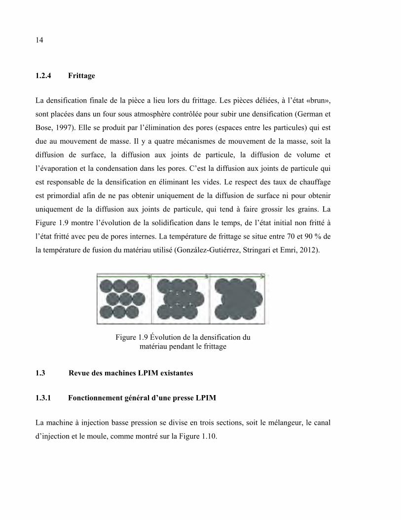
uniquement de la diffusion aux joints de particule, qui tend à faire grossir les grains. La
Figure 1.9 montre l’évolution de la solidification dans le temps, de l’état initial non fritté à
l’état fritté avec peu de pores internes. La température de frittage se situe entre 70 et 90 % de
la température de fusion du matériau utilisé (González-Gutiérrez, Stringari et Emri, 2012).
Figure 1.9 Évolution de la densification du matériau pendant le frittage
1.3 Revue des machines LPIM existantes
1.3.1 Fonctionnement général d’une presse LPIM
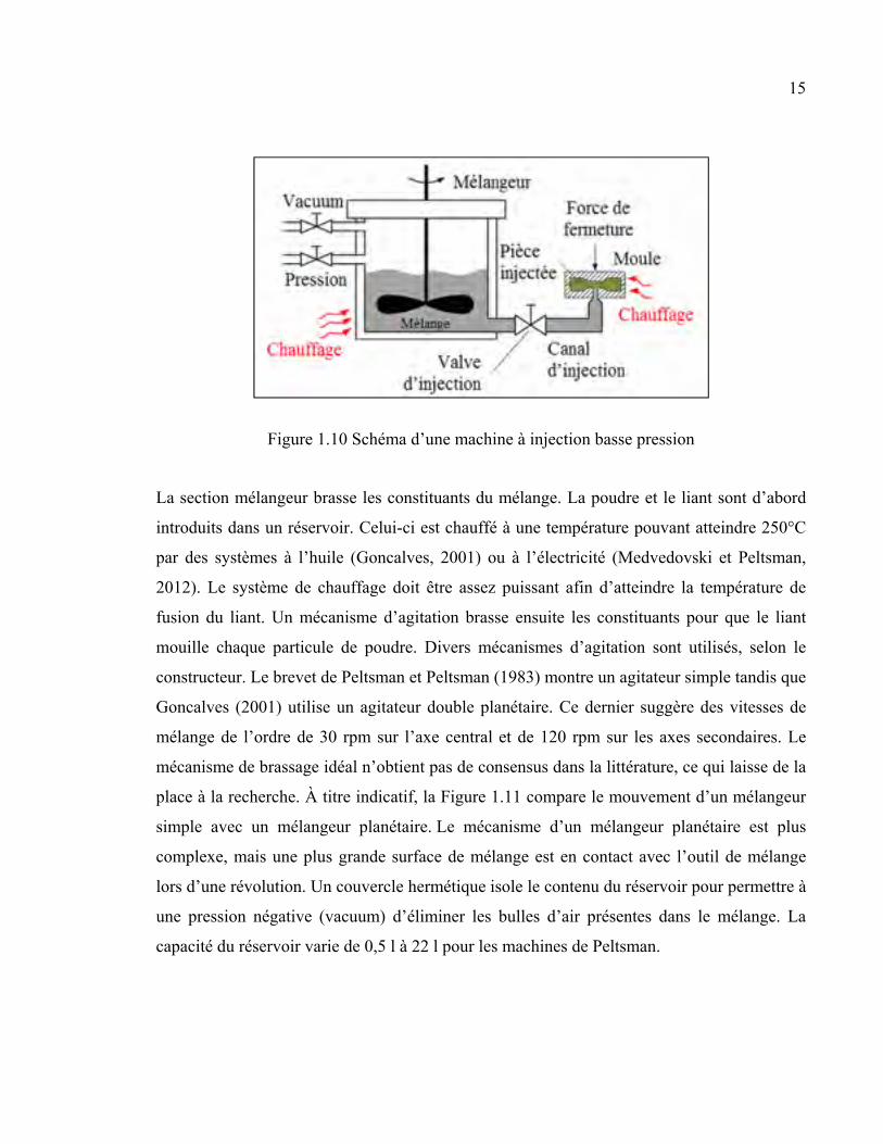
La machine à injection basse pression se divise en trois sections, soit le mélangeur, le canal
d’injection et le moule, comme montré sur la Figure 1.10.
15
Figure 1.10 Schéma d’une machine à injection basse pression
La section mélangeur brasse les constituants du mélange. La poudre et le liant sont d’abord
introduits dans un réservoir. Celui-ci est chauffé à une température pouvant atteindre 250°C
par des systèmes à l’huile (Goncalves, 2001) ou à l’électricité (Medvedovski et Peltsman,
2012). Le système de chauffage doit être assez puissant afin d’atteindre la température de
fusion du liant. Un mécanisme d’agitation brasse ensuite les constituants pour que le liant
mouille chaque particule de poudre. Divers mécanismes d’agitation sont utilisés, selon le
constructeur. Le brevet de Peltsman et Peltsman (1983) montre un agitateur simple tandis que
Goncalves (2001) utilise un agitateur double planétaire. Ce dernier suggère des vitesses de
mélange de l’ordre de 30 rpm sur l’axe central et de 120 rpm sur les axes secondaires. Le
mécanisme de brassage idéal n’obtient pas de consensus dans la littérature, ce qui laisse de la
place à la recherche. À titre indicatif, la Figure 1.11 compare le mouvement d’un mélangeur
simple avec un mélangeur planétaire. Le mécanisme d’un mélangeur planétaire est plus
complexe, mais une plus grande surface de mélange est en contact avec l’outil de mélange
lors d’une révolution. Un couvercle hermétique isole le contenu du réservoir pour permettre à
une pression négative (vacuum) d’éliminer les bulles d’air présentes dans le mélange. La
capacité du réservoir varie de 0,5 l à 22 l pour les machines de Peltsman.
16
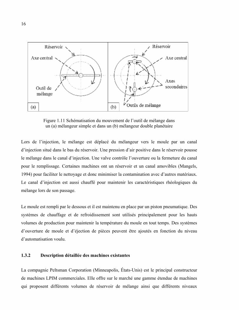
Figure 1.11 Schématisation du mouvement de l’outil de mélange dans un (a) mélangeur simple et dans un (b) mélangeur double planétaire
Lors de l’injection, le mélange est déplacé du mélangeur vers le moule par un canal
d’injection situé dans le bas du réservoir. Une pression d’air positive dans le réservoir pousse
le mélange dans le canal d’injection. Une valve contrôle l’ouverture ou la fermeture du canal
pour le remplissage. Certaines machines ont un réservoir et un canal amovibles (Mangels,
1994) pour faciliter le nettoyage et donc minimiser la contamination avec d’autres matériaux.
Le canal d’injection est aussi chauffé pour maintenir les caractéristiques rhéologiques du
mélange lors de son passage.
Le moule est rempli par le dessous et il est maintenu en place par un piston pneumatique. Des
systèmes de chauffage et de refroidissement sont utilisés principalement pour les hauts
volumes de production pour maintenir la température du moule en tout temps. Des systèmes
d’ouverture de moule et d’éjection de pièces peuvent être ajoutés en fonction du niveau
d’automatisation voulu.
1.3.2 Description détaillée des machines existantes
La compagnie Peltsman Corporation (Minneapolis, États-Unis) est le principal constructeur
de machines LPIM commerciales. Elle offre sur le marché une gamme étendue de machines
qui proposent différents volumes de réservoir de mélange ainsi que différents niveaux
17
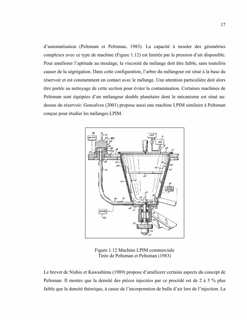
d’automatisation (Peltsman et Peltsman, 1983). La capacité à mouler des géométries
complexes avec ce type de machine (Figure 1.12) est limitée par la pression d’air disponible.
Pour améliorer l’aptitude au moulage, la viscosité du mélange doit être faible, sans toutefois
causer de la ségrégation. Dans cette configuration, l’arbre du mélangeur est situé à la base du
réservoir et est constamment en contact avec le mélange. Une attention particulière doit alors
être portée au nettoyage de cette section pour éviter la contamination. Certaines machines de
Peltsman sont équipées d’un mélangeur double planétaire dont le mécanisme est situé au-
dessus du réservoir. Goncalves (2001) propose aussi une machine LPIM similaire à Peltsman
conçue pour étudier les mélanges LPIM.
Figure 1.12 Machine LPIM commerciale Tirée de Peltsman et Peltsman (1983)
Le brevet de Nishio et Kawashima (1989) propose d’améliorer certains aspects du concept de
Peltsman. Il montre que la densité des pièces injectées par ce procédé est de 2 à 5 % plus
faible que la densité théorique, à cause de l’incorporation de bulle d’air lors de l’injection. La
18
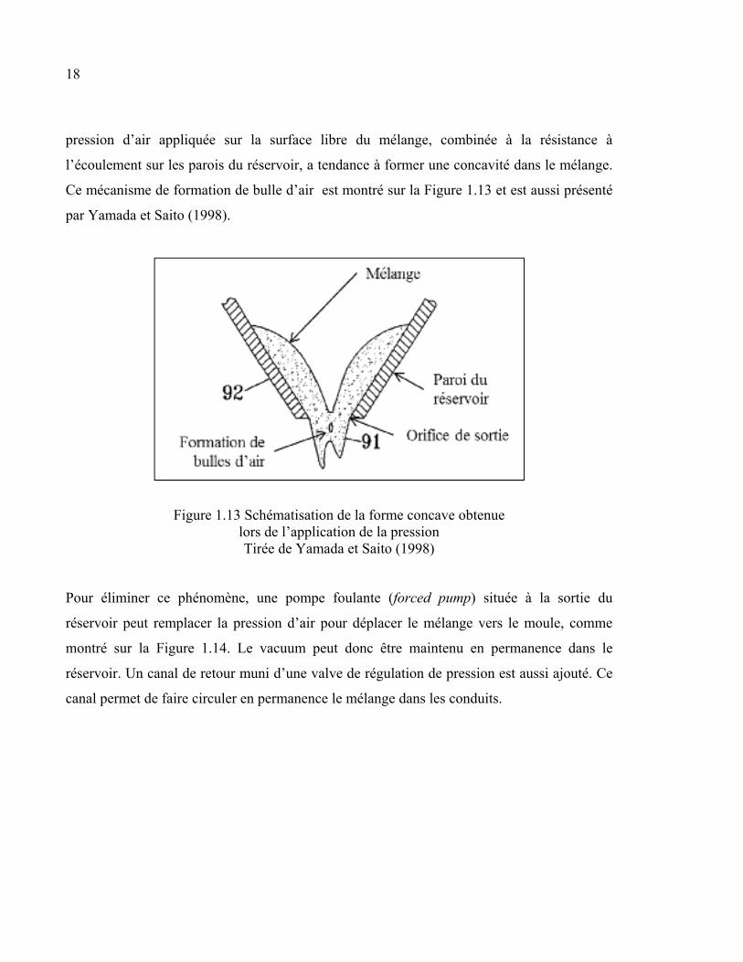
pression d’air appliquée sur la surface libre du mélange, combinée à la résistance à
l’écoulement sur les parois du réservoir, a tendance à former une concavité dans le mélange.
Ce mécanisme de formation de bulle d’air est montré sur la Figure 1.13 et est aussi présenté
par Yamada et Saito (1998).
Figure 1.13 Schématisation de la forme concave obtenue lors de l’application de la pression Tirée de Yamada et Saito (1998)
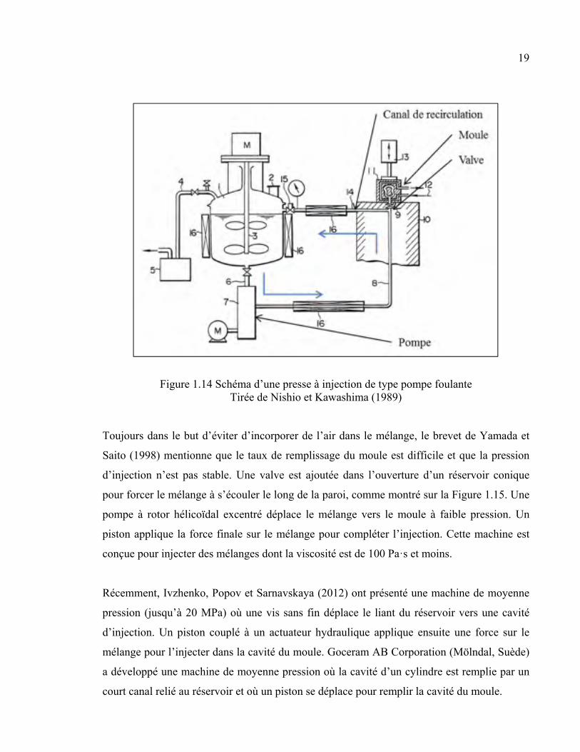
Pour éliminer ce phénomène, une pompe foulante (forced pump) située à la sortie du
réservoir peut remplacer la pression d’air pour déplacer le mélange vers le moule, comme
montré sur la Figure 1.14. Le vacuum peut donc être maintenu en permanence dans le
réservoir. Un canal de retour muni d’une valve de régulation de pression est aussi ajouté. Ce
canal permet de faire circuler en permanence le mélange dans les conduits.
19
Figure 1.14 Schéma d’une presse à injection de type pompe foulante Tirée de Nishio et Kawashima (1989)
Toujours dans le but d’éviter d’incorporer de l’air dans le mélange, le brevet de Yamada et
Saito (1998) mentionne que le taux de remplissage du moule est difficile et que la pression
d’injection n’est pas stable. Une valve est ajoutée dans l’ouverture d’un réservoir conique
pour forcer le mélange à s’écouler le long de la paroi, comme montré sur la Figure 1.15. Une
pompe à rotor hélicoïdal excentré déplace le mélange vers le moule à faible pression. Un
piston applique la force finale sur le mélange pour compléter l’injection. Cette machine est
conçue pour injecter des mélanges dont la viscosité est de 100 Pa·s et moins.
Récemment, Ivzhenko, Popov et Sarnavskaya (2012) ont présenté une machine de moyenne
pression (jusqu’à 20 MPa) où une vis sans fin déplace le liant du réservoir vers une cavité
d’injection. Un piston couplé à un actuateur hydraulique applique ensuite une force sur le
mélange pour l’injecter dans la cavité du moule. Goceram AB Corporation (Mölndal, Suède)
a développé une machine de moyenne pression où la cavité d’un cylindre est remplie par un
court canal relié au réservoir et où un piston se déplace pour remplir la cavité du moule.
20
Figure 1.15 Schéma d’une presse à injection de type pompe proportionnelle et piston
Tirée de Yamada et Saito (1998)
Le tableau suivant résume les caractéristiques des presses à injection basse pression
conventionnelles décrites dans cette section. Toutes ces solutions proposent une machine
munie d’un canal d’injection dans lequel le mélange peut demeurer stagnant entre les
injections et donc ségréger pour des mélanges à très basse viscosité.
Tableau 1.2 Résumé des inventeurs de presses à injection et les techniques utilisées par chacun
Inventeur[Ref] Réservoir Canal d’injection Valve d’injection Méthode d’injection
Peltsman et Peltsman (1983)
X X X Pression d’air
Goncalves (2001) X X X Pression d’air
Nishio et Kawashima (1989)
X X X Pompe
Yamada et Saito (1998)
X X X Pompe proportionnelle
+ piston
Ivzhenko, Popov et Sarnavskaya (2012)
X X Pompe à vis + piston
Keizo (1989) X X Pression d’air + piston
Goceram (Pompe et Brandt, 2001)
X X Piston
21
1.3.3 Difficultés et limites des presses LPIM existantes
Une difficulté majeure du procédé LPIM, bien identifiée par les auteurs précédemment cités,
est l’incorporation de bulles d’air dans le mélange lors de l’injection. La plupart des auteurs
tendent vers l’abandon de l’injection par pression d’air afin de résoudre ce problème.
Toutefois, certains désavantages découlent de ces nouvelles techniques d’injection.
Premièrement, le nettoyage est nécessaire, particulièrement lorsque des matériaux différents
sont utilisés d’une série à l’autre. La contamination est problématique puisque des matériaux
de nature différente ne fritteront pas de la même manière et causeront des défauts dans les
pièces. Les besoins en nettoyage augmentent forcément lorsque les procédés font appel à des
systèmes additionnels. Les valves de contrôle, les pompes, les vis sans fin et les capteurs qui
sont en contact avec le mélange doivent être démontés entièrement. Les mélanges peu
visqueux ont la capacité de s’introduire facilement dans les mécanismes, comme le montre
l’exemple de la Figure 1.16. De plus, le risque de contamination par l’usure (frottement)
augmente pour les systèmes mécaniques (Hidalgo et al., 2013). Dans une perspective de
production industrielle, cet inconvénient peut-être viable considérant que le même matériau
est constamment utilisé. Cependant, dans un cadre de recherche, où plusieurs matériaux sont
susceptibles d’être étudiés, le temps et la qualité de nettoyage sont des facteurs à considérer.
22
Figure 1.16 Exemple d’infiltration de mélange dans un mécanisme d’une presse à injection
qui doit être nettoyé
Deuxièmement, les mélanges de très faible viscosité sont utilisés pour mouler les pièces de
formes complexes et pour compenser la faible pression d’injection. Cependant, une faible
viscosité entraîne plus rapidement la séparation des phases lorsque le mélange n’est pas
brassé. Chacun des concepts présentés à la section 1.3 est équipé d’un canal d’injection dans
lequel le mélange est stationnaire entre deux séquences d'injection. La machine de Nishio et
Kawashima (1989) semble contourner le problème puisque le canal de recirculation permet
au mélange d’être constamment en mouvement et de retourner dans le réservoir pour être
mélangé. Toutefois, une petite quantité de mélange peut rester immobile à l’intérieur et à la
sortie de la valve d’injection. La Figure 1.17 montre une pièce injectée avec du mélange
fortement ségrégé. La séparation des phases est clairement visible. Cet exemple est extrême
et le problème est facilement détectable. Toutefois, une légère ségrégation peut ne pas être
visible après l’injection. Les distorsions apparaîtront après le frittage.
23
Figure 1.17 Exemple de séparation des phases d’une pièce fortement ségrégée
Troisièmement, l’aptitude au moulage d’un mélange est la capacité de celui-ci à mouler des
pièces sans défaut, comme un moulage incomplet. Jenni et al. (2008) définissent l’aptitude au
moulage comme étant la comparaison des longueurs d’injection maximales avant
solidification, pour les mêmes conditions d’injection, comme montrée sur la Figure 1.18.
Puisque le moule est froid, le mélange se solidifie sur les parois. L’espace central entre les
parois diminue peu à peu jusqu’à ce qu’il soit complètement fermé. L’élément qui englobe
toutes des variables liées à la composition des mélanges (types de liant, proportion poudre-
liant, taille et forme de la poudre) est la viscosité, puisque la température et la vitesse
d’injection d’un essai d’aptitude au moulage sont constantes.
Figure 1.18 Schématisation de la longueur d’injection pour trois mélanges différents
24
Plusieurs auteurs utilisent donc la viscosité des mélanges pour caractériser l’aptitude au
moulage d’un mélange. Karatas et al. (2008) ont réalisé des essais d’injection pour comparer
les mesures de rhéologie. Ces essais ont cependant été réalisés avec des machines HPIM. Les
caractéristiques propres au LPIM comme la faible pression d’injection, la ségrégation des
mélanges et l’incorporation de bulles d’air ne sont pas considérées pour les mélanges HPIM.
1.4 Problématique et objectifs
L’objectif principal du projet est de concevoir et fabriquer une machine à injection basse
pression qui corrige les problèmes des machines existantes dans une perspective d’utilisation
en laboratoire, soit :
• minimiser (voire éliminer) la ségrégation dans le canal d’injection, dans les valves de
contrôle et dans tout autre mécanisme, phénomène qui est amplifié par l’injection de
mélange à très basse viscosité;
• minimiser l’incorporation de bulles d’air;
• faciliter le nettoyage.
Pour ce faire, des mesures de thermogravimétrie, de tomographies, et d’aptitude au moulage
ont été mises en œuvre pour établir les paramètres de fonctionnement et de valider que
l’injection des mélanges à très basse viscosité est possible sans générer de ségrégation à
travers la presse pendant les temps morts du procédé.
CHAPITRE 2
MÉTHODOLOGIE
Ce chapitre est un aperçu des détails techniques de la presse à injection basse pression et de
la méthodologie proposée pour valider cet appareil. Le développement du concept est
présenté dans le cahier des charges de l’ANNEXE I. La demande de brevet provisoire « A
low-pressure powder injection molding machine and method » à l’ANNEXE II fait état de la
conception détaillée de la presse ainsi que de son fonctionnement. Le dessin d’assemblage, la
liste de pièces et le schéma électrique sont quant à eux présentés à l’ANNEXE III et à
l’ANNEXE IV.
2.1 Méthodologie de conception et de fabrication de la presse
2.1.1 Analyse du besoin
Comme montré à la Figure 1.2, la machine LPIM exécute la préparation du mélange et
l’injection. Le besoin essentiel est de mettre en forme des pièces à partir de poudres
métalliques pour obtenir des données permettant d’étudier le procédé. Il en découle deux
besoins, soit :
• l’homogénéisation des constituants du mélange;
• l’injection du mélange dans la cavité d’un moule.
Les éléments suivants sont des cibles et des requis qui sont nécessaires afin que la machine
soit fonctionnelle et adaptée à l’échelle laboratoire (voir l’ANNEXE I pour plus de détails) :
• la préparation du mélange doit se faire pour une petite quantité, soit 1 kg maximum pour
diminuer le coût des essais;
• le brassage doit se faire sous vide à température maximale de 130 °C, qui correspond à
une température supérieure à la température de fusion des liants de type cire
généralement utilisés (l’effet de l’évaporation du liant dans le temps devra être évalué
dans un prochain travail);
26
• le mélange ne doit pas subir de ségrégation (la fraction volumique de poudre doit être
constante ± 0,5 vol. %);
• le contrôle de la température doit être de maximum ± 2 °C (qui correspond à la précision
d’un thermocouple type K) dans toute la machine (du mélangeur jusqu’à l’entrée du
moule) pour éviter la variation des propriétés rhéologique du mélange;
• la pression d’injection doit être de maximum 1,0 MPa, ou 0,7 MPa si la pression d’air est
utilisée;
• l’augmentation de la pression doit être progressive (taux d’augmentation de la pression à
déterminer);
• les dimensions de la base du moule doivent être de 150 mm sur 300 mm pour mettre en
forme des échantillons de traction plats suivant la norme ASTM E8M (ASTM, 2013) (les
moules futurs pourront cependant être plus petits, en fonction de la pièce à mouler);
• la température du mélange doit être mesurée dans chaque section de la machine (la
mesure indirecte de la température du mélange par l’entremise des parois du réservoir, du
conduit d’alimentation et du moule est acceptable, mais devra être quantifié pour valider
les gradients de température et le temps d’équilibre);
• la pression dans le mélangeur et la pression d’injection doivent être mesurées;
• la vitesse de rotation du mélangeur doit être contrôlée;
• le nettoyage de la machine doit être facile et rapide pour les mélanges à base de
polymères typiques au MIM.
2.1.2 Développement du concept final et essais préliminaires
Lors de la génération des concepts, l’accent a été mis sur l’élimination de la ségrégation.
Pour l’éviter, le mélange doit être continuellement mélangé. Il doit passer le moins de temps
possible dans le canal d’injection. Le concept associé à cet état est le fonctionnement d’une
seringue, qui s’introduit dans un réservoir (Figure 2.1a), puise un volume désiré (Figure 2.1b)
et l’injecte ensuite dans une cavité (Figure 2.1c). Cela permet de vider complètement le canal
d’injection et d’éviter la ségrégation.
27
Figure 2.1 Principe de fonctionnement du concept presse (a) Insertion d’une seringue dans un réservoir, (b) ponction d’un
volume prédéfini et (c) injection dans une cavité
Pour garder le mélange continuellement en mouvement, le mélangeur doit être constamment
en marche. Pour éviter que le mécanisme soit en contact avec le mélange, celui-ci doit être
au-dessus du réservoir. De plus, une ouverture doit être faite dans le réservoir pour permettre
à la seringue de puiser le volume désiré. Une valve ne peut pas être envisagée, car le mélange
peut rester pris dans le mécanisme. Le concept associé à cette problématique est un
mécanisme de cisaillement du mélange. Une ouverture est faite dans le bas du réservoir. La
seringue est placée sur une table qui se déplace de gauche à droite qui bouche l’ouverture du
réservoir. D’abord, le piston de la seringue puise le volume désiré du réservoir (Figure 2.2a).
Ensuite, la table et la seringue coulissent, ce qui cisaille le mélange présent dans l’orifice de
sortie du réservoir et bouche l'ouverture (Figure 2.2b).
Figure 2.2 (a) Seringue fixée à une table qui puise un volume du réservoir et (b) qui coulisse
pour boucher l’ouverture
28
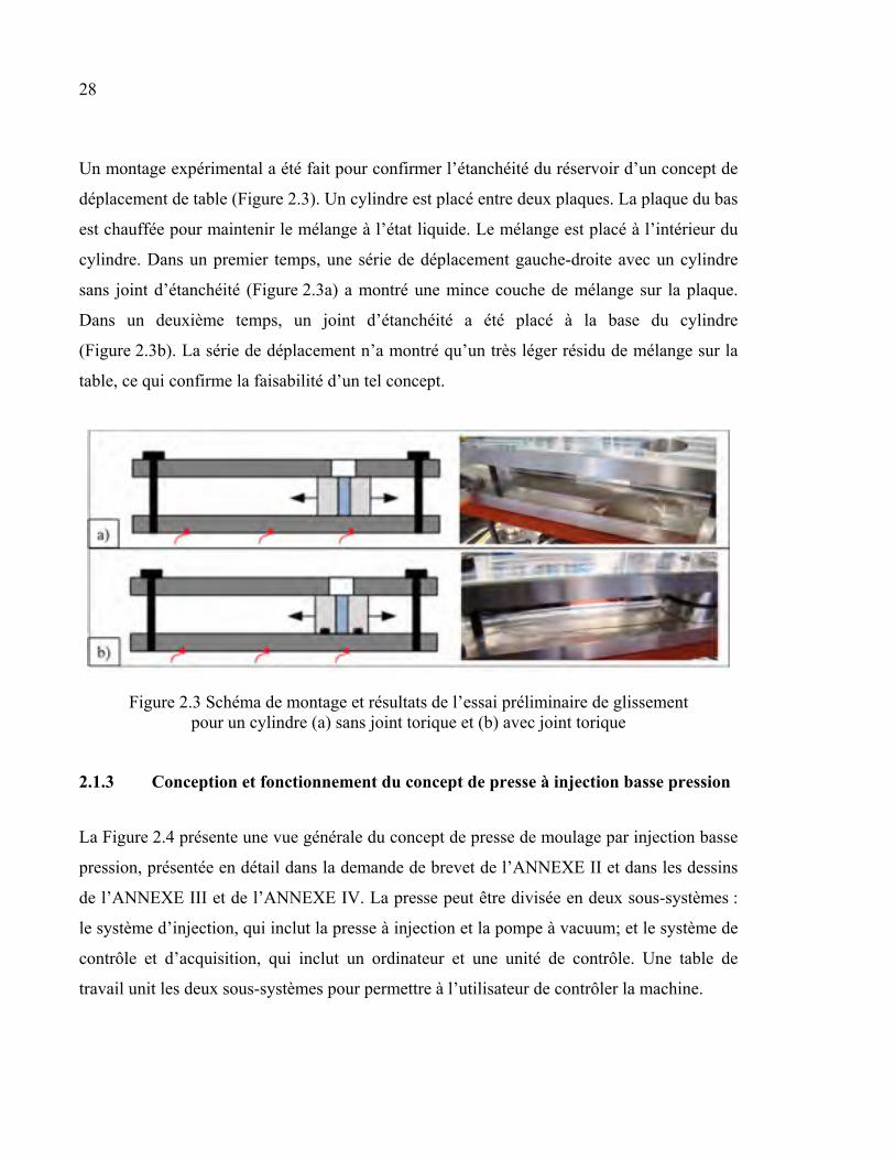
Un montage expérimental a été fait pour confirmer l’étanchéité du réservoir d’un concept de
déplacement de table (Figure 2.3). Un cylindre est placé entre deux plaques. La plaque du bas
est chauffée pour maintenir le mélange à l’état liquide. Le mélange est placé à l’intérieur du
cylindre. Dans un premier temps, une série de déplacement gauche-droite avec un cylindre
sans joint d’étanchéité (Figure 2.3a) a montré une mince couche de mélange sur la plaque.
Dans un deuxième temps, un joint d’étanchéité a été placé à la base du cylindre
(Figure 2.3b). La série de déplacement n’a montré qu’un très léger résidu de mélange sur la
table, ce qui confirme la faisabilité d’un tel concept.
Figure 2.3 Schéma de montage et résultats de l’essai préliminaire de glissement pour un cylindre (a) sans joint torique et (b) avec joint torique
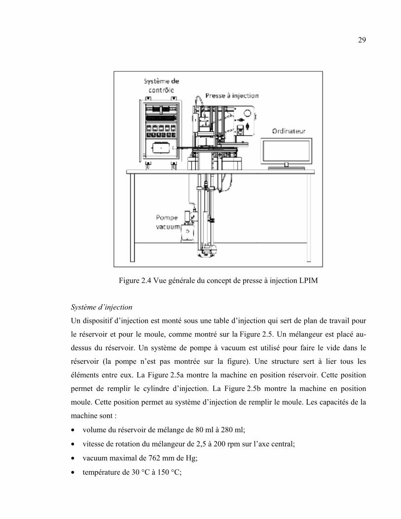
2.1.3 Conception et fonctionnement du concept de presse à injection basse pression
La Figure 2.4 présente une vue générale du concept de presse de moulage par injection basse
pression, présentée en détail dans la demande de brevet de l’ANNEXE II et dans les dessins
de l’ANNEXE III et de l’ANNEXE IV. La presse peut être divisée en deux sous-systèmes :
le système d’injection, qui inclut la presse à injection et la pompe à vacuum; et le système de
contrôle et d’acquisition, qui inclut un ordinateur et une unité de contrôle. Une table de
travail unit les deux sous-systèmes pour permettre à l’utilisateur de contrôler la machine.
29
Figure 2.4 Vue générale du concept de presse à injection LPIM
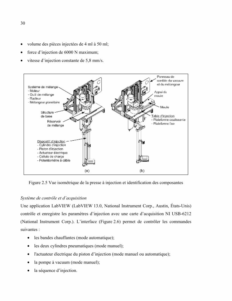
Système d’injection
Un dispositif d’injection est monté sous une table d’injection qui sert de plan de travail pour
le réservoir et pour le moule, comme montré sur la Figure 2.5. Un mélangeur est placé au-
dessus du réservoir. Un système de pompe à vacuum est utilisé pour faire le vide dans le
réservoir (la pompe n’est pas montrée sur la figure). Une structure sert à lier tous les
éléments entre eux. La Figure 2.5a montre la machine en position réservoir. Cette position
permet de remplir le cylindre d’injection. La Figure 2.5b montre la machine en position
moule. Cette position permet au système d’injection de remplir le moule. Les capacités de la
machine sont :
• volume du réservoir de mélange de 80 ml à 280 ml;
• vitesse de rotation du mélangeur de 2,5 à 200 rpm sur l’axe central;
• vacuum maximal de 762 mm de Hg;
• température de 30 °C à 150 °C;
30
• volume des pièces injectées de 4 ml à 50 ml;
• force d’injection de 6000 N maximum;
• vitesse d’injection constante de 5,8 mm/s.
Figure 2.5 Vue isométrique de la presse à injection et identification des composantes
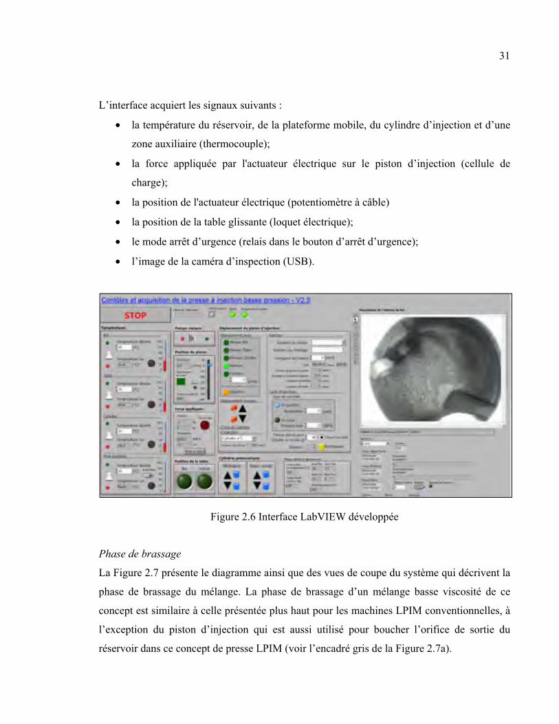
Système de contrôle et d’acquisition
Une application LabVIEW (LabVIEW 13.0, National Instrument Corp., Austin, États-Unis)
contrôle et enregistre les paramètres d’injection avec une carte d’acquisition NI USB-6212
(National Instrument Corp.). L’interface (Figure 2.6) permet de contrôler les commandes
suivantes :
• les bandes chauffantes (mode automatique);
• les deux cylindres pneumatiques (mode manuel);
• l'actuateur électrique du piston d’injection (mode manuel ou automatique);
• la pompe à vacuum (mode manuel);
• la séquence d’injection.
31
L’interface acquiert les signaux suivants :
• la température du réservoir, de la plateforme mobile, du cylindre d’injection et d’une
zone auxiliaire (thermocouple);
• la force appliquée par l'actuateur électrique sur le piston d’injection (cellule de
charge);
• la position de l'actuateur électrique (potentiomètre à câble)
• la position de la table glissante (loquet électrique);
• le mode arrêt d’urgence (relais dans le bouton d’arrêt d’urgence);
• l’image de la caméra d’inspection (USB).
Figure 2.6 Interface LabVIEW développée
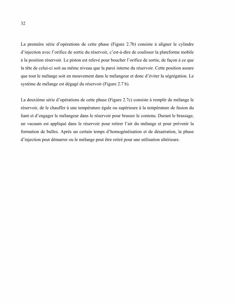
Phase de brassage
La Figure 2.7 présente le diagramme ainsi que des vues de coupe du système qui décrivent la
phase de brassage du mélange. La phase de brassage d’un mélange basse viscosité de ce
concept est similaire à celle présentée plus haut pour les machines LPIM conventionnelles, à
l’exception du piston d’injection qui est aussi utilisé pour boucher l’orifice de sortie du
réservoir dans ce concept de presse LPIM (voir l’encadré gris de la Figure 2.7a).
32
La première série d’opérations de cette phase (Figure 2.7b) consiste à aligner le cylindre
d’injection avec l’orifice de sortie du réservoir, c’est-à-dire de coulisser la plateforme mobile
à la position réservoir. Le piston est relevé pour boucher l’orifice de sortie, de façon à ce que
la tête de celui-ci soit au même niveau que la paroi interne du réservoir. Cette position assure
que tout le mélange soit en mouvement dans le mélangeur et donc d’éviter la ségrégation. Le
système de mélange est dégagé du réservoir (Figure 2.7 b).
La deuxième série d’opérations de cette phase (Figure 2.7c) consiste à remplir de mélange le
réservoir, de le chauffer à une température égale ou supérieure à la température de fusion du
liant et d’engager le mélangeur dans le réservoir pour brasser le contenu. Durant le brassage,
un vacuum est appliqué dans le réservoir pour retirer l’air du mélange et pour prévenir la
formation de bulles. Après un certain temps d’homogénéisation et de désaération, la phase
d’injection peut démarrer ou le mélange peut être retiré pour une utilisation ultérieure.
33
Figure 2.7 (a) Diagramme et (b-c) vues de coupe partielles de la presse à injection qui décrivent la phase de brassage du mélange
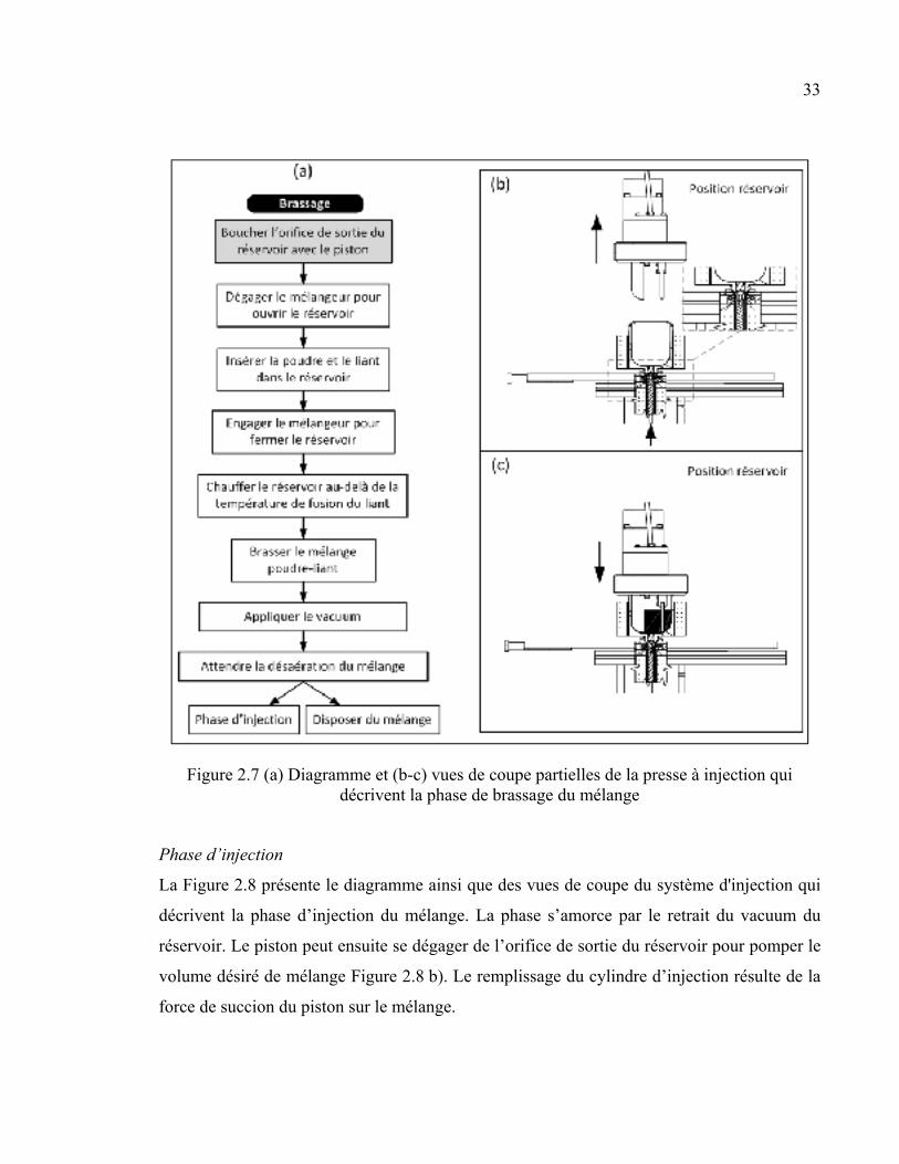
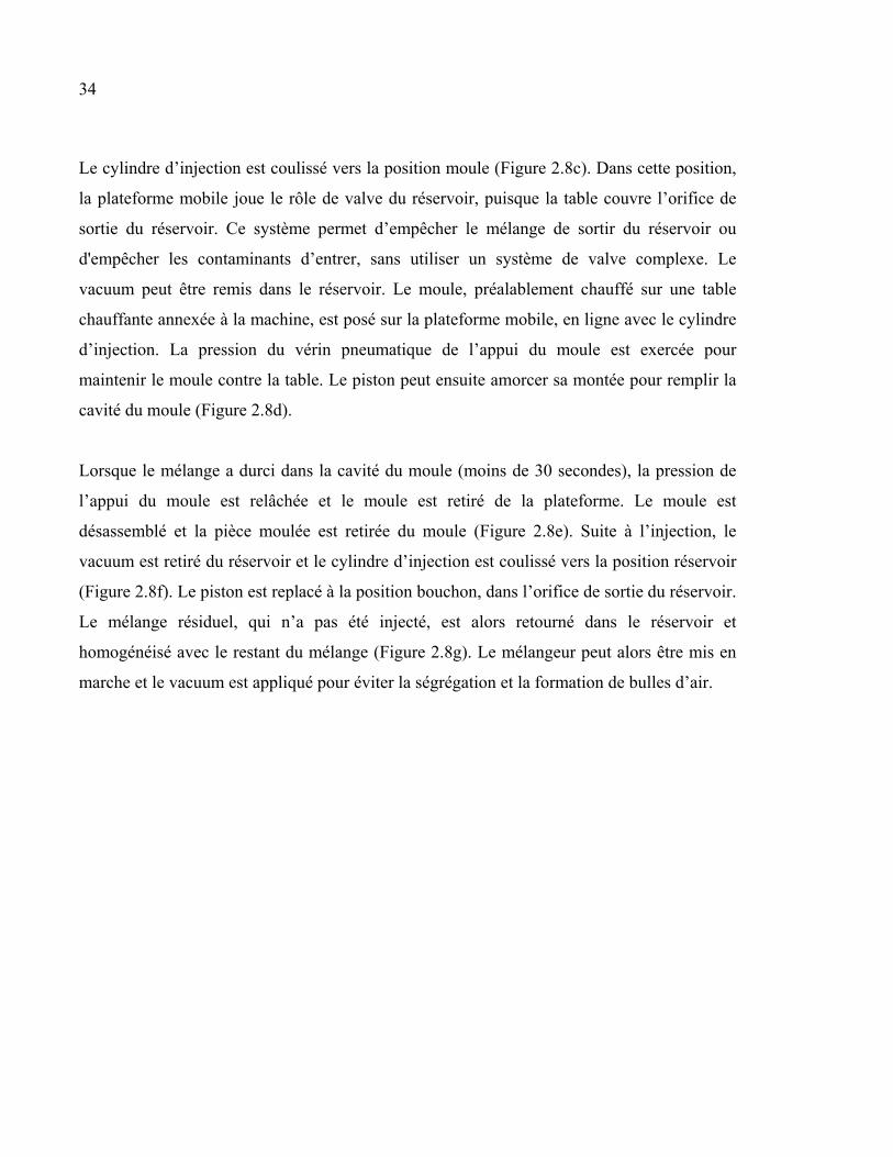
Phase d’injection
La Figure 2.8 présente le diagramme ainsi que des vues de coupe du système d'injection qui
décrivent la phase d’injection du mélange. La phase s’amorce par le retrait du vacuum du
réservoir. Le piston peut ensuite se dégager de l’orifice de sortie du réservoir pour pomper le
volume désiré de mélange Figure 2.8 b). Le remplissage du cylindre d’injection résulte de la
force de succion du piston sur le mélange.
34
Le cylindre d’injection est coulissé vers la position moule (Figure 2.8c). Dans cette position,
la plateforme mobile joue le rôle de valve du réservoir, puisque la table couvre l’orifice de
sortie du réservoir. Ce système permet d’empêcher le mélange de sortir du réservoir ou
d'empêcher les contaminants d’entrer, sans utiliser un système de valve complexe. Le
vacuum peut être remis dans le réservoir. Le moule, préalablement chauffé sur une table
chauffante annexée à la machine, est posé sur la plateforme mobile, en ligne avec le cylindre
d’injection. La pression du vérin pneumatique de l’appui du moule est exercée pour
maintenir le moule contre la table. Le piston peut ensuite amorcer sa montée pour remplir la
cavité du moule (Figure 2.8d).
Lorsque le mélange a durci dans la cavité du moule (moins de 30 secondes), la pression de
l’appui du moule est relâchée et le moule est retiré de la plateforme. Le moule est
désassemblé et la pièce moulée est retirée du moule (Figure 2.8e). Suite à l’injection, le
vacuum est retiré du réservoir et le cylindre d’injection est coulissé vers la position réservoir
(Figure 2.8f). Le piston est replacé à la position bouchon, dans l’orifice de sortie du réservoir.
Le mélange résiduel, qui n’a pas été injecté, est alors retourné dans le réservoir et
homogénéisé avec le restant du mélange (Figure 2.8g). Le mélangeur peut alors être mis en
marche et le vacuum est appliqué pour éviter la ségrégation et la formation de bulles d’air.
35
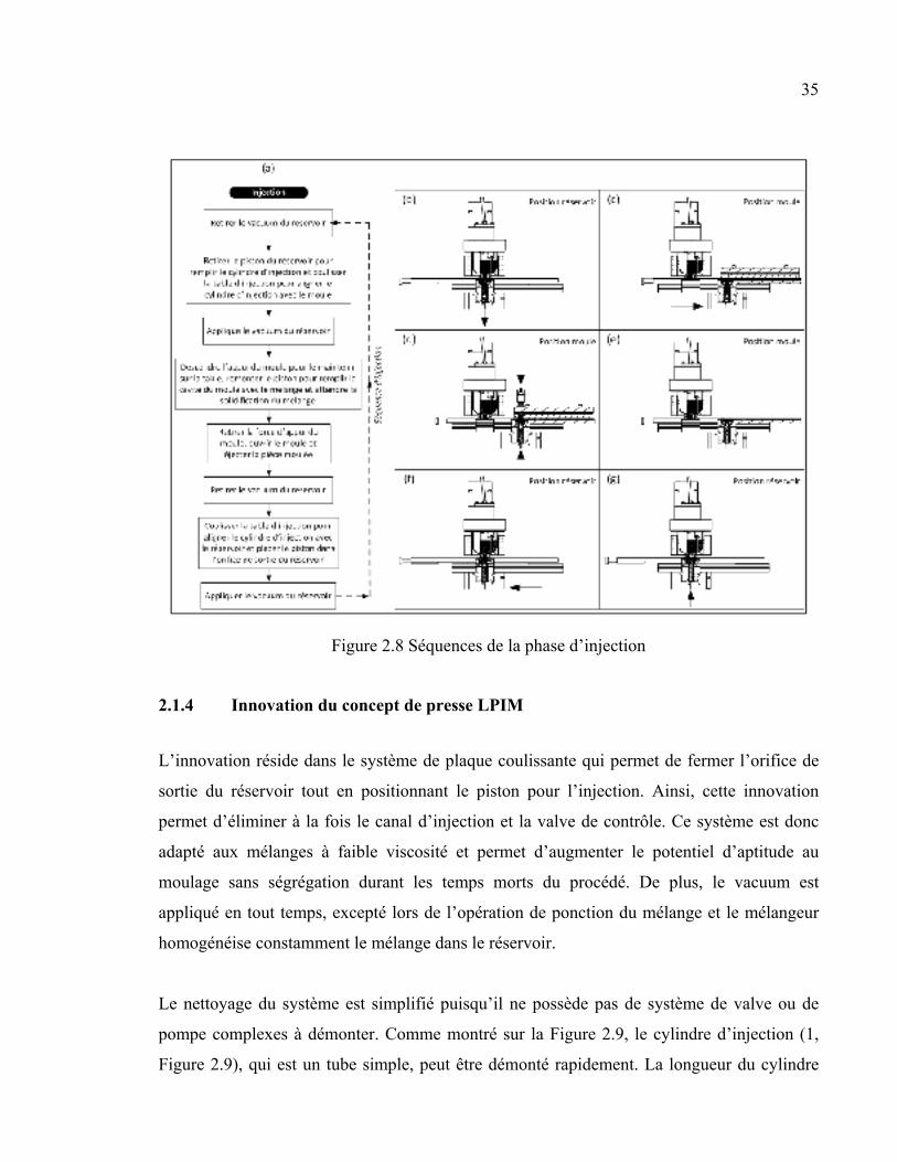
Figure 2.8 Séquences de la phase d’injection
2.1.4 Innovation du concept de presse LPIM
L’innovation réside dans le système de plaque coulissante qui permet de fermer l’orifice de
sortie du réservoir tout en positionnant le piston pour l’injection. Ainsi, cette innovation
permet d’éliminer à la fois le canal d’injection et la valve de contrôle. Ce système est donc
adapté aux mélanges à faible viscosité et permet d’augmenter le potentiel d’aptitude au
moulage sans ségrégation durant les temps morts du procédé. De plus, le vacuum est
appliqué en tout temps, excepté lors de l’opération de ponction du mélange et le mélangeur
homogénéise constamment le mélange dans le réservoir.
Le nettoyage du système est simplifié puisqu’il ne possède pas de système de valve ou de
pompe complexes à démonter. Comme montré sur la Figure 2.9, le cylindre d’injection (1,
Figure 2.9), qui est un tube simple, peut être démonté rapidement. La longueur du cylindre
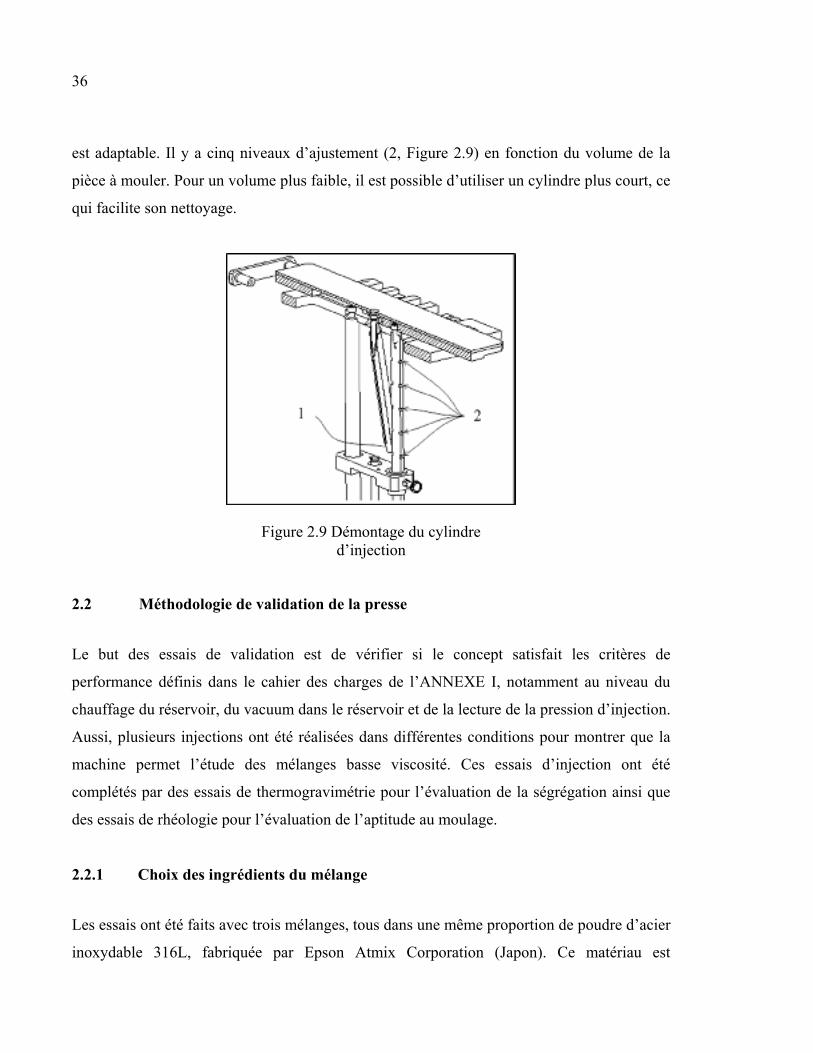
36
est adaptable. Il y a cinq niveaux d’ajustement (2, Figure 2.9) en fonction du volume de la
pièce à mouler. Pour un volume plus faible, il est possible d’utiliser un cylindre plus court, ce
qui facilite son nettoyage.
Figure 2.9 Démontage du cylindre d’injection
2.2 Méthodologie de validation de la presse
Le but des essais de validation est de vérifier si le concept satisfait les critères de
performance définis dans le cahier des charges de l’ANNEXE I, notamment au niveau du
chauffage du réservoir, du vacuum dans le réservoir et de la lecture de la pression d’injection.
Aussi, plusieurs injections ont été réalisées dans différentes conditions pour montrer que la
machine permet l’étude des mélanges basse viscosité. Ces essais d’injection ont été
complétés par des essais de thermogravimétrie pour l’évaluation de la ségrégation ainsi que
des essais de rhéologie pour l’évaluation de l’aptitude au moulage.
2.2.1 Choix des ingrédients du mélange
Les essais ont été faits avec trois mélanges, tous dans une même proportion de poudre d’acier
inoxydable 316L, fabriquée par Epson Atmix Corporation (Japon). Ce matériau est
37
représentatif des poudres métalliques utilisées pour le moulage LPIM tant au niveau de sa
forme (principalement sphérique) et de sa taille moyenne de 6.7 µm. La poudre d’acier
inoxydable 316L est bien connue et elle a retenu l’attention de plusieurs auteurs (Dvorak,
Barriere et Gelin, 2005; Ibrahim, Muhamad et Sulong, 2011; Sotomayor, Varez et Levenfeld,
2010). De plus, elle est peu dispendieuse comparativement à de la poudre d’Inconel, par
exemple.
Les liants sont tous composés à la base de cire de paraffine. Le premier liant est uniquement
composé de cire de paraffine (PW) (Sigma-Aldrich, États-Unis). Ce mélange a servi de
référence. De l’acide stéarique (SA) est ajouté dans le second liant pour diminuer la viscosité.
Ce mélange a servi notamment à l’évaluation de la ségrégation, puisque sa très basse
viscosité favorise ce phénomène. Le troisième liant est composé de cire de paraffine, d’acide
stéarique et d’éthylène vinyle acétate (EVA). L’ajout d’EVA permet d’épaissir le liant tout
en profitant de l’effet mouillage du SA. Les détails de la composition des mélanges sont
disponibles dans le Tableau 3.2.
Pour trouver la température d’injection minimale, la température de fusion des trois mélanges
de liant a été déterminée par une analyse de calorimétrie différentielle à balayage (DSC). Les
résultats de cette analyse sont disponibles à l’ANNEXE V.
2.2.2 Définition des paramètres d’utilisation de la machine
Température du mélange
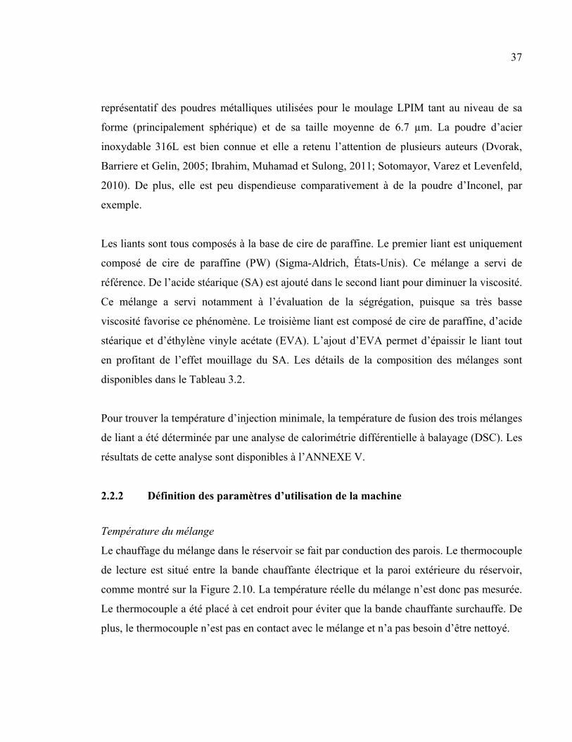
Le chauffage du mélange dans le réservoir se fait par conduction des parois. Le thermocouple
de lecture est situé entre la bande chauffante électrique et la paroi extérieure du réservoir,
comme montré sur la Figure 2.10. La température réelle du mélange n’est donc pas mesurée.
Le thermocouple a été placé à cet endroit pour éviter que la bande chauffante surchauffe. De
plus, le thermocouple n’est pas en contact avec le mélange et n’a pas besoin d’être nettoyé.
38
Figure 2.10 Vue de coupe du réservoir montrant la position du thermocouple de lecture de température du réservoir
Un essai de mesure de la température du mélange dans le réservoir a été fait avec un mélange
30PW-10SA (voir Tableau 3.2 pour les détails de composition). Un thermocouple est inséré
dans l’ouverture de la caméra pour mesurer la température réelle du mélange avec le
mélangeur en fonction. L’essai commence à une température de mélange de 50 °C. Pour
chaque essai, la commande de température est de 50 °C + 10*i °C, jusqu’à 110 °C. La
température est notée en fonction du temps, jusqu’à l’atteinte d’un plateau. Ce résultat
permet de déterminer l’écart entre la température commandée et la température réelle sur
toute la plage d’utilisation. Les résultats sont présentés à la section 3.1.1.
Temps minimum du vacuum
Pour enlever complètement l’air dans le mélange, le vacuum doit être maintenu un certain
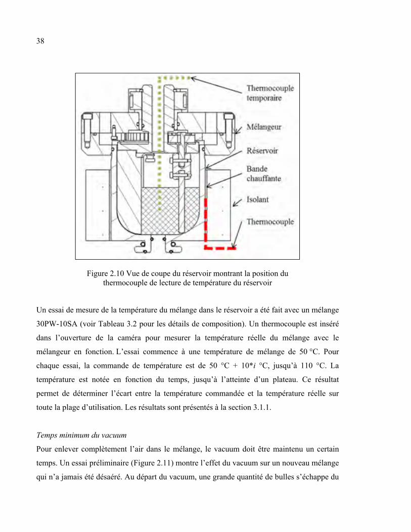
temps. Un essai préliminaire (Figure 2.11) montre l’effet du vacuum sur un nouveau mélange
qui n’a jamais été désaéré. Au départ du vacuum, une grande quantité de bulles s’échappe du
39
mélange (Figure 2.11a). Après 40 minutes de vacuum, le mélange devient lisse sans présence
visuelle de bulles (Figure 2.11b).
Figure 2.11 Aspect du mélange dans le réservoir (vue de dessus) pour un vacuum de (a) 1 minute et (b) 40 minutes
Toutefois, pour confirmer qu’aucune bulle n’est présente dans le mélange lorsqu’il apparaît
lisse, quatre pièces, soumises à quatre temps de vacuum (0 min, 15 min, 30 min et 45 min),
ont été injectées et analysées par tomographie. Une nouvelle préparation du mélange 30PW-
10SA a été utilisée. Les résultats sont présentés à la section 3.2.
Lecture de la pression
Comparativement aux machines LPIM conventionnelles qui utilisent la pression d’air pour
déplacer le mélange, la machine conçue dans ce projet utilise un piston muni d’un joint
torique pour assurer l’étanchéité dans le cylindre d’injection. Le joint torique s’oppose au
déplacement du piston en raison de la force de frottement avec la paroi du cylindre
d’injection. Cette force est mesurée par la cellule de charge. La force est convertie en
pression à partir de la section du cylindre.
Un essai d’injection à vide, donc sans mélange, a été fait pour mesurer dans un premier
temps l’effet du frottement du joint torique. La répétition de l’essai permet dans un deuxième
temps d’évaluer la répétabilité des résultats. L’essai a été réalisé à 90 °C pour retrouver les
40
conditions d’injection normales. L’essai a été fait à quatre reprises. Les résultats sont
présentés dans la section 3.1.2.
2.2.3 Essais thermogravimétriques
La principale revendication de ce concept de presse LPIM est que la ségrégation dans la
presse est éliminée. Pour vérifier cette affirmation, un essai de ségrégation provoqué a été
réalisé avec un mélange 30PW10SA, qui est très peu visqueux. Un volume de mélange est
retiré du réservoir par le cylindre d’injection. Un échantillon de mélange est ensuite prélevé à
la surface libre du cylindre (dessus) à quatre intervalles (0 min, 1 min, 5 min, 10 min),
comme montré sur la Figure 2.12. La température du piston est maintenue à 90 °C. Les
échantillons ont ensuite subi une analyse thermogravimétrique (TGA) pour déterminer la
proportion de chaque constituant du mélange. Les résultats sont présentés dans la section 3.2.
Figure 2.12 Vue de coupe du cylindre d’injection montrant l’endroit où l’échantillon de mélange ségrégé est prélevé
2.2.4 Essais d’injection
Dans un premier temps, les trois mélanges énoncés à la section 2.2.1 ont subi un essai de
rhéologie pour mesurer la viscosité en fonction du taux de cisaillement. Ensuite, chaque
mélange a été injecté pour former des barres de traction. Cette injection permet de déterminer

41
la pression maximale d’injection. Ces mêmes mélanges ont aussi été injectés dans un moule
de forme spirale. Cette géométrie permet de mesurer la longueur injectée. Les résultats de
rhéologie et d’injection sont présentés et comparés à la section 3.2.

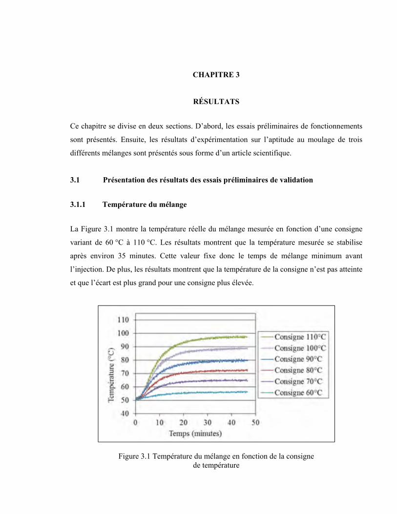
CHAPITRE 3
RÉSULTATS
Ce chapitre se divise en deux sections. D’abord, les essais préliminaires de fonctionnements
sont présentés. Ensuite, les résultats d’expérimentation sur l’aptitude au moulage de trois
différents mélanges sont présentés sous forme d’un article scientifique.
3.1 Présentation des résultats des essais préliminaires de validation
3.1.1 Température du mélange
La Figure 3.1 montre la température réelle du mélange mesurée en fonction d’une consigne
variant de 60 °C à 110 °C. Les résultats montrent que la température mesurée se stabilise
après environ 35 minutes. Cette valeur fixe donc le temps de mélange minimum avant
l’injection. De plus, les résultats montrent que la température de la consigne n’est pas atteinte
et que l’écart est plus grand pour une consigne plus élevée.
Figure 3.1 Température du mélange en fonction de la consigne de température
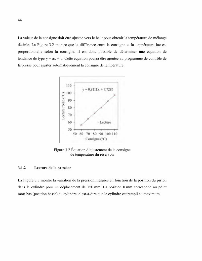
44
La valeur de la consigne doit être ajustée vers le haut pour obtenir la température de mélange
désirée. La Figure 3.2 montre que la différence entre la consigne et la température lue est
proportionnelle selon la consigne. Il est donc possible de déterminer une équation de
tendance de type y = ax + b. Cette équation pourra être ajoutée au programme de contrôle de
la presse pour ajuster automatiquement la consigne de température.
Figure 3.2 Équation d’ajustement de la consigne de température du réservoir
3.1.2 Lecture de la pression
La Figure 3.3 montre la variation de la pression mesurée en fonction de la position du piston
dans le cylindre pour un déplacement de 150 mm. La position 0 mm correspond au point
mort bas (position basse) du cylindre, c’est-à-dire que le cylindre est rempli au maximum.
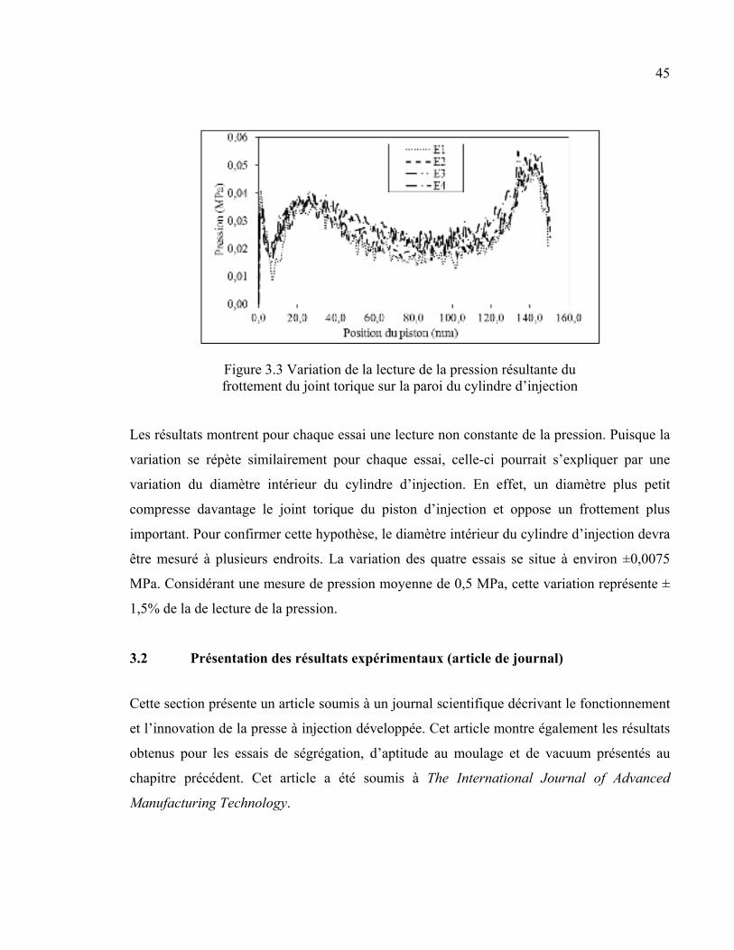
45
Figure 3.3 Variation de la lecture de la pression résultante du frottement du joint torique sur la paroi du cylindre d’injection
Les résultats montrent pour chaque essai une lecture non constante de la pression. Puisque la
variation se répète similairement pour chaque essai, celle-ci pourrait s’expliquer par une
variation du diamètre intérieur du cylindre d’injection. En effet, un diamètre plus petit
compresse davantage le joint torique du piston d’injection et oppose un frottement plus
important. Pour confirmer cette hypothèse, le diamètre intérieur du cylindre d’injection devra
être mesuré à plusieurs endroits. La variation des quatre essais se situe à environ ±0,0075
MPa. Considérant une mesure de pression moyenne de 0,5 MPa, cette variation représente ±
1,5% de la de lecture de la pression.
3.2 Présentation des résultats expérimentaux (article de journal)
Cette section présente un article soumis à un journal scientifique décrivant le fonctionnement
et l’innovation de la presse à injection développée. Cet article montre également les résultats
obtenus pour les essais de ségrégation, d’aptitude au moulage et de vacuum présentés au
chapitre précédent. Cet article a été soumis à The International Journal of Advanced
Manufacturing Technology.
46
DEVELOPMENT OF AN INJECTION CONCEPT USED IN LOW-PRESSURE
POWDER INJECTION MOLDING
S. G. Lamarre 1, V. Demers 1*, J. F. Chatelain 1
1École de technologie supérieure, 1100 Notre-Dame West, Montreal, QC H3C 1K3, Canada
e-mail: Simon G. Lamarre ([email protected]); Jean-François Chatelain
*Corresponding author: Vincent Demers; Tel: 1 514 396-8590; Fax: 514 396-8530; E-mail:
Cette section de chapitre a été soumise comme article pour publication dans The
International Journal of Advanced Manufacturing Technology. Soumis le 13 octobre 2016.
Abstract:
In low-pressure powder injection molding, the injection presses are equipped with an
interconnecting pipe in which the segregation of feedstocks may occur during the dead time
of the process. This segregation phenomenon limits the use of low-viscosity feedstocks
leading to a decrease in the capacity to produce more complex-shaped components. The full
moldability potential of the process is still limited by the injection method proposed in the
commercial machines. A new injection concept was developed to increase the moldability of
powder-binder mixtures, while avoiding segregation within the injection press. This
innovative injection system consists in eliminating the interconnecting pipe and injection
valve by using a sliding platform concept which was adapted for transportation of the
feedstock from the container to the mold cavity. Validation of the injection system was
performed using three wax-based feedstocks. Injection profiles obtained with two different
molds were correlated with the rheological behavior of the feedstocks, and
thermogravimetric analyses were used to quantify the segregation within the system. An
experimental simulation of segregation within the machine confirmed that the injection
47
method avoids segregation for a feedstock exhibiting a viscosity as low as 0.1 Pa·s. The best
moldability properties were obtained with feedstock containing paraffin wax and stearic acid.
Keywords:
Powder injection molding (PIM); injection press; viscosity; segregation; moldability;
feedstock.
3.2.1 Introduction
The cost-effective and small series fabrication (customization) of complex shape metallic
parts with the proper dimensional and geometric tolerances is one of the main goals in
advanced manufacturing industry. As a manufacturing technology, low-pressure powder
injection molding (LPIM) encompasses all these requirements simultaneously. This rapid
manufacturing process consists in mixing metallic or ceramic powder with molten polymeric
binder to obtain a feedstock which is injected into a mold cavity to generate a complex shape.
As presented by Heaney (2012c), the binder is completely removed during debinding and
sintering treatments to obtain a near-net shape dense metallic component. Over the past 20
years, Mangels (1994) showed that the conventional high-pressure powder injection molding
(HPIM) process (injection pressure of up to 200 MPa) has transitioned to LPIM by taking
advantage of low-viscosity feedstocks (e.g., < 10 Pa∙s) to achieve high moldability during
injection at a pressure lower than 0.7 MPa. As used by Zorzi, Perottoni et Da Jornada (2003)
in ceramics forming, the LPIM technology has quickly become attractive for the
development of high value-added metallic parts. Ibrahim et al. (2014) investigated the
potential of superalloys for aerospace applications, while Aslam et al. (2016) developed
stainless steel feedstocks.
A key to the successful injection of feedstock at low pressure lies in the low-viscosity
properties of the wax-based binder. As demonstrated by Schlechtriemen et al. (2013), the
paraffin waxes can be used as the main constituents in LPIM powder-binder mixtures. Li et
al. (2007) investigated the effect of surfactant agents and demonstrated that this constituent
48
can act as a bridge between metallic powder and other constituents to enhance the
homogeneity and the injection properties of the feedstock. A thickening agent is generally
used to increase the viscosity of the mixture in order to prevent powder-binder separation.
Stearic acid, ethylene vinyl acetate, and low-density polyethylene are extensively used as the
secondary constituents in LPIM feedstocks.
The advantages and the limitations of the LPIM technology are directly related to the
rheological properties of low-viscosity feedstocks. As demonstrated by Arifin et al. (2015) in
conventional HPIM process as well as by Loebbecke, Knitter et Haußelt (2009) in LPIM
process, the rheological properties correspond to pseudoplastic behavior. Also, several
feedstock parameters may affect the viscosity of the mixture. Mannschatz, Muller et Moritz
(2011) observed that an increase in powder sphericity produces a decrease in the viscosity of
feedstock. Sotomayor, Varez et Levenfeld (2010) measured that a decrease in particle size
leads to an increase in viscosity. Li, Liujun et Khalil (2007) demonstrated that an increase in
the volume fraction of binder generates a decrease in viscosity, but may lead to debinding
and sintering defects. As summarized by Ibrahim, Muhamad et Sulong (2011), it is well
accepted that an increase in feedstock temperature produces a decrease in the viscosity of
feedstock. A decrease in viscosity of the powder-binder mixture results in higher moldability
at a lower pressure. A lower injection pressure directly minimizes the deformations of the
mold and favors a calm mold filling, resulting in the fabrication of defect-free parts (cavities,
weld line, internal stresses, etc.), while reducing the cost of the tooling and the injection
machine. However, the use of low-viscosity feedstocks may lead to segregation of the
constituents. Jenni, Zauner et Stampfl (2009) shown that the segregation is generated mainly
by gravity, an improper mixing method, and a high-pressure gradient during the molding
process. This parameter must be minimized in order to prevent distortions, cracks, voids,
warping and the heterogeneous shrinkage of sintered parts. Moldability and segregation are
linked to the rheological behavior of the feedstock. Using feedstock viscosity that is too low
should easily fill the mold cavity, but this would also lead to the segregation of trapped
feedstock that remains idle within the injection machine during the process dead times.
49
Several concepts for the conventional low-pressure injection molding machine for metallic or
ceramic powder were presented. Over 30 years ago, the invention presented by Peltsman et
Peltsman (1983) proposed a complete system having a conical container with an interior
agitator and heating means for keeping the material inside the container in a slurry form.
Their manufacturing experience in low-pressure injection molding of ceramic was recently
reviewed by Medvedovski et Peltsman (2012). Goncalves (2001) has proposed a similar
concept of injection machine: following homogenization and deaeration of the feedstock, the
container is pressurized in order to flow out the feedstock from the container to the mold
cavity through an interconnecting pipe and an injection valve. Nishio et Kawashima (1989)
presented a concept for feedstock transportation without the use of air pressure. A slurry
pump is connected to the outlet of a feedstock container, supplying the mold with feedstock
through a pipe. Several valves (including an injection valve) are used to control the flow of
the feedstock through the slurry pump, the inlet of the container, and the gate of the mold.
Yamada et Saito (1998) proposed another concept of the LPIM machine having a system to
prevent air from being entrapped in the feedstock during injection. There, a proportional
pump is connected to a discharge port of a feedstock container, supplying the mold at a
constant rate via a feeder pipe and a cylinder. More recently, Ivzhenko, Popov et
Sarnavskaya (2012) proposed a similar concept of an injection machine adapted for
micro/nanosized powder injection molding. A screw pump is used for the transportation of
the feedstock from the container to the injection piston, in which the powder-binder mixture
is injected into the mold cavity using an injection pressure up to 20 MPa. Keizo (1989)
proposed a machine combining a conventional system with a second pressure stage piston.
Goceram AB Corporation (Mölndal, Sweden) developed a medium pressure powder
injection molding technology using a similar piston system, as presented by Pompe et Brandt
(2001). In its system, the powder-binder mixture flows from the container to the injection
cylinder through an interconnecting pipe. The piston of the injection cylinder is then used to
transport the feedstock to the mold cavity.
All the injection molding machines presented above are equipped with an interconnecting
pipe for transportation of the feedstock between the container and the mold. Since is not
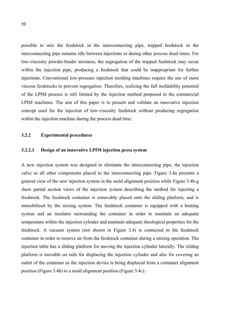
50
possible to mix the feedstock in the interconnecting pipe, trapped feedstock in the
interconnecting pipe remains idle between injections or during other process dead times. For
low-viscosity powder-binder mixtures, the segregation of the trapped feedstock may occur
within the injection pipe, producing a feedstock that could be inappropriate for further
injections. Conventional low-pressure injection molding machines require the use of more
viscous feedstocks to prevent segregation. Therefore, realizing the full moldability potential
of the LPIM process is still limited by the injection method proposed in the commercial
LPIM machines. The aim of this paper is to present and validate an innovative injection
concept used for the injection of low-viscosity feedstock without producing segregation
within the injection machine during the process dead time.
3.2.2 Experimental procedures
3.2.2.1 Design of an innovative LPIM injection press system
A new injection system was designed to eliminate the interconnecting pipe, the injection
valve or all other components placed in the interconnecting pipe. Figure 3.4a presents a
general view of the new injection system in the mold alignment position while Figure 3.4b-g
show partial section views of the injection system describing the method for injecting a
feedstock. The feedstock container is removably placed onto the sliding platform, and is
immobilized by the mixing system. The feedstock container is equipped with a heating
system and an insulator surrounding the container in order to maintain an adequate
temperature within the injection cylinder and maintain adequate rheological properties for the
feedstock. A vacuum system (not shown in Figure 3.4) is connected to the feedstock
container in order to remove air from the feedstock container during a mixing operation. The
injection table has a sliding platform for moving the injection cylinder laterally. The sliding
platform is movable on rails for displacing the injection cylinder and also for covering an
outlet of the container as the injection device is being displaced from a container alignment
position (Figure 3.4b) to a mold alignment position (Figure 3.4c).
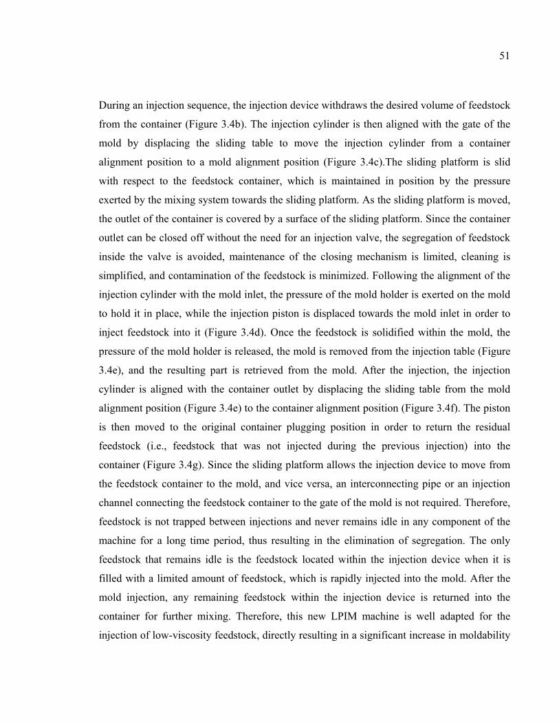
51
During an injection sequence, the injection device withdraws the desired volume of feedstock
from the container (Figure 3.4b). The injection cylinder is then aligned with the gate of the
mold by displacing the sliding table to move the injection cylinder from a container
alignment position to a mold alignment position (Figure 3.4c).The sliding platform is slid
with respect to the feedstock container, which is maintained in position by the pressure
exerted by the mixing system towards the sliding platform. As the sliding platform is moved,
the outlet of the container is covered by a surface of the sliding platform. Since the container
outlet can be closed off without the need for an injection valve, the segregation of feedstock
inside the valve is avoided, maintenance of the closing mechanism is limited, cleaning is
simplified, and contamination of the feedstock is minimized. Following the alignment of the
injection cylinder with the mold inlet, the pressure of the mold holder is exerted on the mold
to hold it in place, while the injection piston is displaced towards the mold inlet in order to
inject feedstock into it (Figure 3.4d). Once the feedstock is solidified within the mold, the
pressure of the mold holder is released, the mold is removed from the injection table (Figure
3.4e), and the resulting part is retrieved from the mold. After the injection, the injection
cylinder is aligned with the container outlet by displacing the sliding table from the mold
alignment position (Figure 3.4e) to the container alignment position (Figure 3.4f). The piston
is then moved to the original container plugging position in order to return the residual
feedstock (i.e., feedstock that was not injected during the previous injection) into the
container (Figure 3.4g). Since the sliding platform allows the injection device to move from
the feedstock container to the mold, and vice versa, an interconnecting pipe or an injection
channel connecting the feedstock container to the gate of the mold is not required. Therefore,
feedstock is not trapped between injections and never remains idle in any component of the
machine for a long time period, thus resulting in the elimination of segregation. The only
feedstock that remains idle is the feedstock located within the injection device when it is
filled with a limited amount of feedstock, which is rapidly injected into the mold. After the
mold injection, any remaining feedstock within the injection device is returned into the
container for further mixing. Therefore, this new LPIM machine is well adapted for the
injection of low-viscosity feedstock, directly resulting in a significant increase in moldability
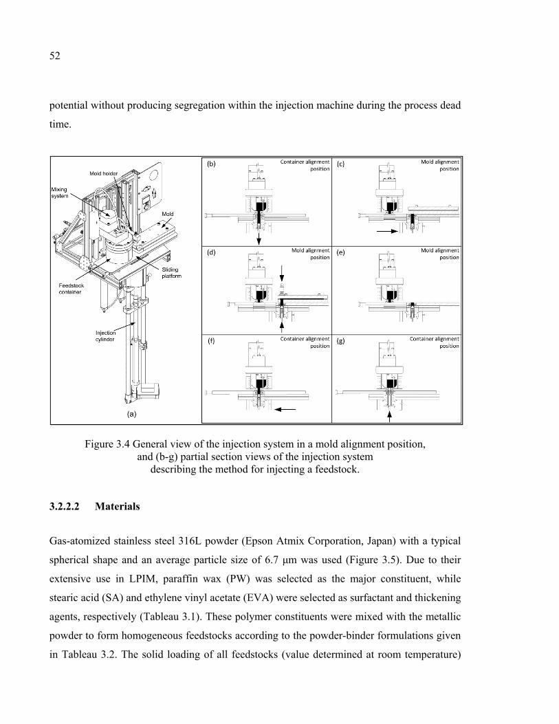
52
potential without producing segregation within the injection machine during the process dead
time.
Figure 3.4 General view of the injection system in a mold alignment position, and (b-g) partial section views of the injection system
describing the method for injecting a feedstock.
3.2.2.2 Materials
Gas-atomized stainless steel 316L powder (Epson Atmix Corporation, Japan) with a typical
spherical shape and an average particle size of 6.7 μm was used (Figure 3.5). Due to their
extensive use in LPIM, paraffin wax (PW) was selected as the major constituent, while
stearic acid (SA) and ethylene vinyl acetate (EVA) were selected as surfactant and thickening
agents, respectively (Tableau 3.1). These polymer constituents were mixed with the metallic
powder to form homogeneous feedstocks according to the powder-binder formulations given
in Tableau 3.2. The solid loading of all feedstocks (value determined at room temperature)
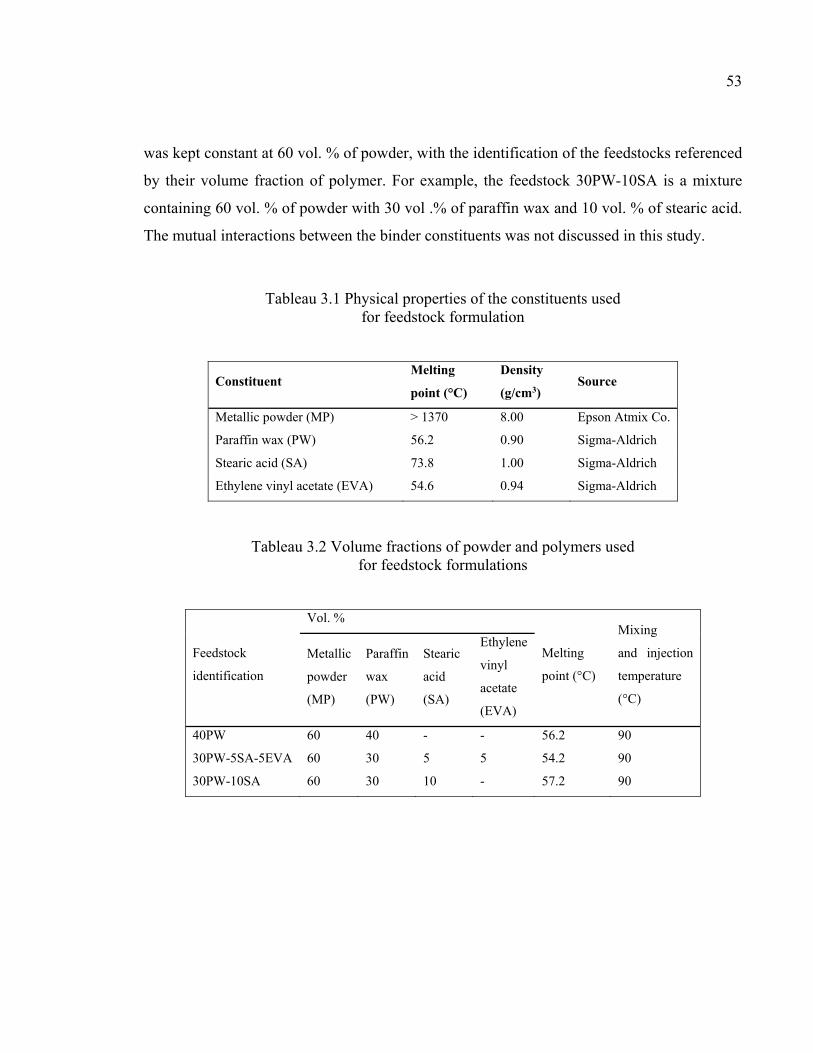
53
was kept constant at 60 vol. % of powder, with the identification of the feedstocks referenced
by their volume fraction of polymer. For example, the feedstock 30PW-10SA is a mixture
containing 60 vol. % of powder with 30 vol .% of paraffin wax and 10 vol. % of stearic acid.
The mutual interactions between the binder constituents was not discussed in this study.
Tableau 3.1 Physical properties of the constituents used for feedstock formulation
Constituent Melting
point (°C)
Density
(g/cm3) Source
Metallic powder (MP) > 1370 8.00 Epson Atmix Co.
Paraffin wax (PW) 56.2 0.90 Sigma-Aldrich
Stearic acid (SA) 73.8 1.00 Sigma-Aldrich
Ethylene vinyl acetate (EVA) 54.6 0.94 Sigma-Aldrich
Tableau 3.2 Volume fractions of powder and polymers used for feedstock formulations
Feedstock
identification
Vol. %
Melting
point (°C)
Mixing
and injection
temperature
(°C)
Metallic
powder
(MP)
Paraffin
wax
(PW)
Stearic
acid
(SA)
Ethylene
vinyl
acetate
(EVA)
40PW 60 40 - - 56.2 90
30PW-5SA-5EVA 60 30 5 5 54.2 90
30PW-10SA 60 30 10 - 57.2 90
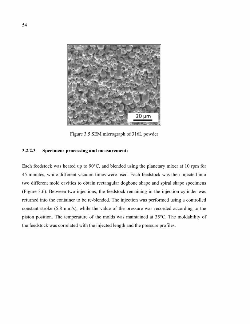
54
Figure 3.5 SEM micrograph of 316L powder
3.2.2.3 Specimens processing and measurements
Each feedstock was heated up to 90°C, and blended using the planetary mixer at 10 rpm for
45 minutes, while different vacuum times were used. Each feedstock was then injected into
two different mold cavities to obtain rectangular dogbone shape and spiral shape specimens
(Figure 3.6). Between two injections, the feedstock remaining in the injection cylinder was
returned into the container to be re-blended. The injection was performed using a controlled
constant stroke (5.8 mm/s), while the value of the pressure was recorded according to the
piston position. The temperature of the molds was maintained at 35°C. The moldability of
the feedstock was correlated with the injected length and the pressure profiles.
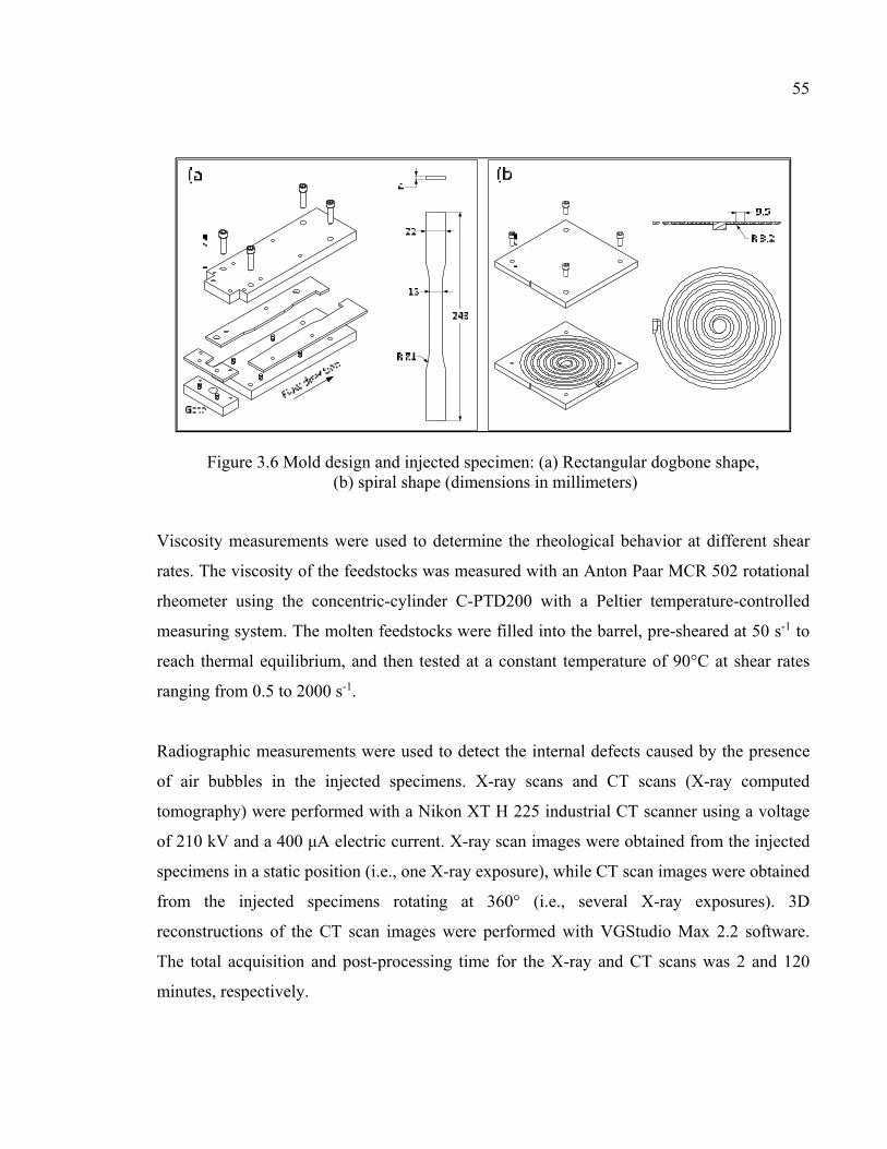
55
Figure 3.6 Mold design and injected specimen: (a) Rectangular dogbone shape, (b) spiral shape (dimensions in millimeters)
Viscosity measurements were used to determine the rheological behavior at different shear
rates. The viscosity of the feedstocks was measured with an Anton Paar MCR 502 rotational
rheometer using the concentric-cylinder C-PTD200 with a Peltier temperature-controlled
measuring system. The molten feedstocks were filled into the barrel, pre-sheared at 50 s-1 to
reach thermal equilibrium, and then tested at a constant temperature of 90°C at shear rates
ranging from 0.5 to 2000 s-1.
Radiographic measurements were used to detect the internal defects caused by the presence
of air bubbles in the injected specimens. X-ray scans and CT scans (X-ray computed
tomography) were performed with a Nikon XT H 225 industrial CT scanner using a voltage
of 210 kV and a 400 μA electric current. X-ray scan images were obtained from the injected
specimens in a static position (i.e., one X-ray exposure), while CT scan images were obtained
from the injected specimens rotating at 360° (i.e., several X-ray exposures). 3D
reconstructions of the CT scan images were performed with VGStudio Max 2.2 software.
The total acquisition and post-processing time for the X-ray and CT scans was 2 and 120
minutes, respectively.
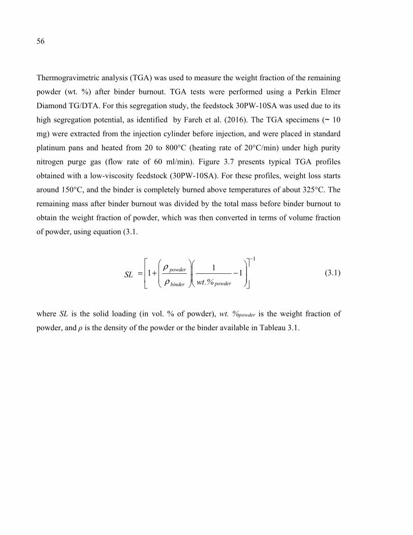
56
Thermogravimetric analysis (TGA) was used to measure the weight fraction of the remaining
powder (wt. %) after binder burnout. TGA tests were performed using a Perkin Elmer
Diamond TG/DTA. For this segregation study, the feedstock 30PW-10SA was used due to its
high segregation potential, as identified by Fareh et al. (2016). The TGA specimens (~ 10
mg) were extracted from the injection cylinder before injection, and were placed in standard
platinum pans and heated from 20 to 800°C (heating rate of 20°C/min) under high purity
nitrogen purge gas (flow rate of 60 ml/min). Figure 3.7 presents typical TGA profiles
obtained with a low-viscosity feedstock (30PW-10SA). For these profiles, weight loss starts
around 150°C, and the binder is completely burned above temperatures of about 325°C. The
remaining mass after binder burnout was divided by the total mass before binder burnout to
obtain the weight fraction of powder, which was then converted in terms of volume fraction
of powder, using equation (3.1.
(3.1)
where SL is the solid loading (in vol. % of powder), wt. %powder is the weight fraction of
powder, and ρ is the density of the powder or the binder available in Tableau 3.1.
1
11 1powder
powderbinder
SLwt.%
ρ
ρ
− = + −
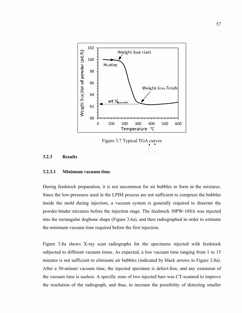
57
Figure 3.7 Typical TGA curves
3.2.3 Results
3.2.3.1 Minimum vacuum time
During feedstock preparation, it is not uncommon for air bubbles to form in the mixtures.
Since the low-pressures used in the LPIM process are not sufficient to compress the bubbles
inside the mold during injection, a vacuum system is generally required to deaerate the
powder-binder mixtures before the injection stage. The feedstock 30PW-10SA was injected
into the rectangular dogbone shape (Figure 3.6a), and then radiographed in order to estimate
the minimum vacuum time required before the first injection.
Figure 3.8a shows X-ray scan radiographs for the specimens injected with feedstock
subjected to different vacuum times. As expected, a low vacuum time ranging from 1 to 15
minutes is not sufficient to eliminate air bubbles (indicated by black arrows in Figure 3.8a).
After a 30-minute vacuum time, the injected specimen is defect-free, and any extension of
the vacuum time is useless. A specific zone of two injected bars was CT-scanned to improve
the resolution of the radiograph, and thus, to increase the possibility of detecting smaller
90
92
94
96
98
100
102
0 100 200 300 400 500 600
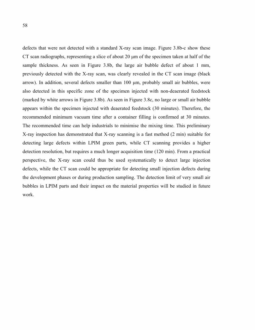
58
defects that were not detected with a standard X-ray scan image. Figure 3.8b-c show these
CT scan radiographs, representing a slice of about 20 μm of the specimen taken at half of the
sample thickness. As seen in Figure 3.8b, the large air bubble defect of about 1 mm,
previously detected with the X-ray scan, was clearly revealed in the CT scan image (black
arrow). In addition, several defects smaller than 100 μm, probably small air bubbles, were
also detected in this specific zone of the specimen injected with non-deaerated feedstock
(marked by white arrows in Figure 3.8b). As seen in Figure 3.8c, no large or small air bubble
appears within the specimen injected with deaerated feedstock (30 minutes). Therefore, the
recommended minimum vacuum time after a container filling is confirmed at 30 minutes.
The recommended time can help industrials to minimise the mixing time. This preliminary
X-ray inspection has demonstrated that X-ray scanning is a fast method (2 min) suitable for
detecting large defects within LPIM green parts, while CT scanning provides a higher
detection resolution, but requires a much longer acquisition time (120 min). From a practical
perspective, the X-ray scan could thus be used systematically to detect large injection
defects, while the CT scan could be appropriate for detecting small injection defects during
the development phases or during production sampling. The detection limit of very small air
bubbles in LPIM parts and their impact on the material properties will be studied in future
work.
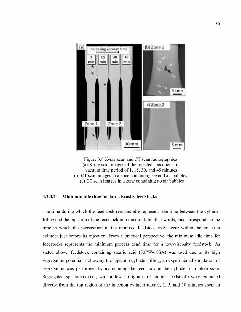
59
Figure 3.8 X-ray scan and CT scan radiographies: (a) X-ray scan images of the injected specimens for vacuum time period of 1, 15, 30, and 45 minutes;
(b) CT scan images in a zone containing several air bubbles; (c) CT scan images in a zone containing no air bubbles
3.2.3.2 Minimum idle time for low-viscosity feedstocks
The time during which the feedstock remains idle represents the time between the cylinder
filling and the injection of the feedstock into the mold. In other words, this corresponds to the
time in which the segregation of the unmixed feedstock may occur within the injection
cylinder just before its injection. From a practical perspective, the minimum idle time for
feedstocks represents the minimum process dead time for a low-viscosity feedstock. As
stated above, feedstock containing stearic acid (30PW-10SA) was used due to its high
segregation potential. Following the injection cylinder filling, an experimental simulation of
segregation was performed by maintaining the feedstock in the cylinder in molten state.
Segregated specimens (i.e., with a few milligrams of molten feedstock) were extracted
directly from the top region of the injection cylinder after 0, 1, 5, and 10 minutes spent in
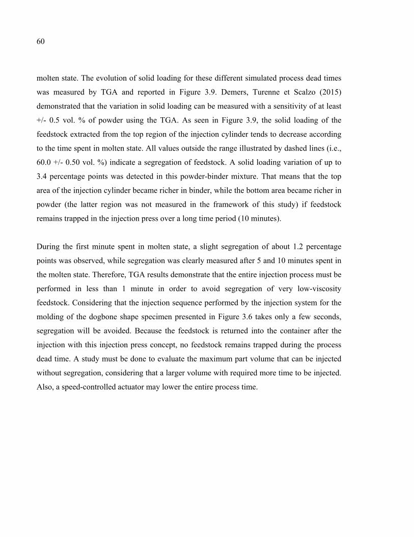
60
molten state. The evolution of solid loading for these different simulated process dead times
was measured by TGA and reported in Figure 3.9. Demers, Turenne et Scalzo (2015)
demonstrated that the variation in solid loading can be measured with a sensitivity of at least
+/- 0.5 vol. % of powder using the TGA. As seen in Figure 3.9, the solid loading of the
feedstock extracted from the top region of the injection cylinder tends to decrease according
to the time spent in molten state. All values outside the range illustrated by dashed lines (i.e.,
60.0 +/- 0.50 vol. %) indicate a segregation of feedstock. A solid loading variation of up to
3.4 percentage points was detected in this powder-binder mixture. That means that the top
area of the injection cylinder became richer in binder, while the bottom area became richer in
powder (the latter region was not measured in the framework of this study) if feedstock
remains trapped in the injection press over a long time period (10 minutes).
During the first minute spent in molten state, a slight segregation of about 1.2 percentage
points was observed, while segregation was clearly measured after 5 and 10 minutes spent in
the molten state. Therefore, TGA results demonstrate that the entire injection process must be
performed in less than 1 minute in order to avoid segregation of very low-viscosity
feedstock. Considering that the injection sequence performed by the injection system for the
molding of the dogbone shape specimen presented in Figure 3.6 takes only a few seconds,
segregation will be avoided. Because the feedstock is returned into the container after the
injection with this injection press concept, no feedstock remains trapped during the process
dead time. A study must be done to evaluate the maximum part volume that can be injected
without segregation, considering that a larger volume with required more time to be injected.
Also, a speed-controlled actuator may lower the entire process time.
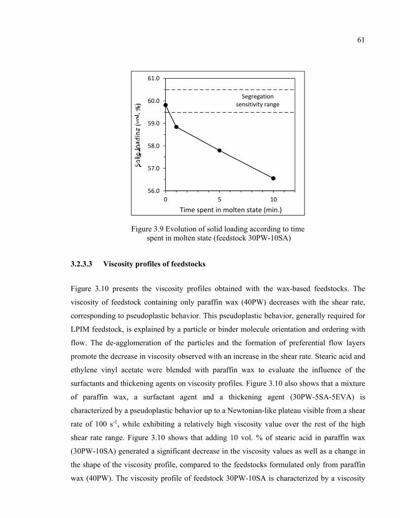
61
Figure 3.9 Evolution of solid loading according to time spent in molten state (feedstock 30PW-10SA)
3.2.3.3 Viscosity profiles of feedstocks
Figure 3.10 presents the viscosity profiles obtained with the wax-based feedstocks. The
viscosity of feedstock containing only paraffin wax (40PW) decreases with the shear rate,
corresponding to pseudoplastic behavior. This pseudoplastic behavior, generally required for
LPIM feedstock, is explained by a particle or binder molecule orientation and ordering with
flow. The de-agglomeration of the particles and the formation of preferential flow layers
promote the decrease in viscosity observed with an increase in the shear rate. Stearic acid and
ethylene vinyl acetate were blended with paraffin wax to evaluate the influence of the
surfactants and thickening agents on viscosity profiles. Figure 3.10 also shows that a mixture
of paraffin wax, a surfactant agent and a thickening agent (30PW-5SA-5EVA) is
characterized by a pseudoplastic behavior up to a Newtonian-like plateau visible from a shear
rate of 100 s-1, while exhibiting a relatively high viscosity value over the rest of the high
shear rate range. Figure 3.10 shows that adding 10 vol. % of stearic acid in paraffin wax
(30PW-10SA) generated a significant decrease in the viscosity values as well as a change in
the shape of the viscosity profile, compared to the feedstocks formulated only from paraffin
wax (40PW). The viscosity profile of feedstock 30PW-10SA is characterized by a viscosity
56.0
57.0
58.0
59.0
60.0
61.0
0 5 10
Time spent in molten state (min.)
Segregation sensitivity range
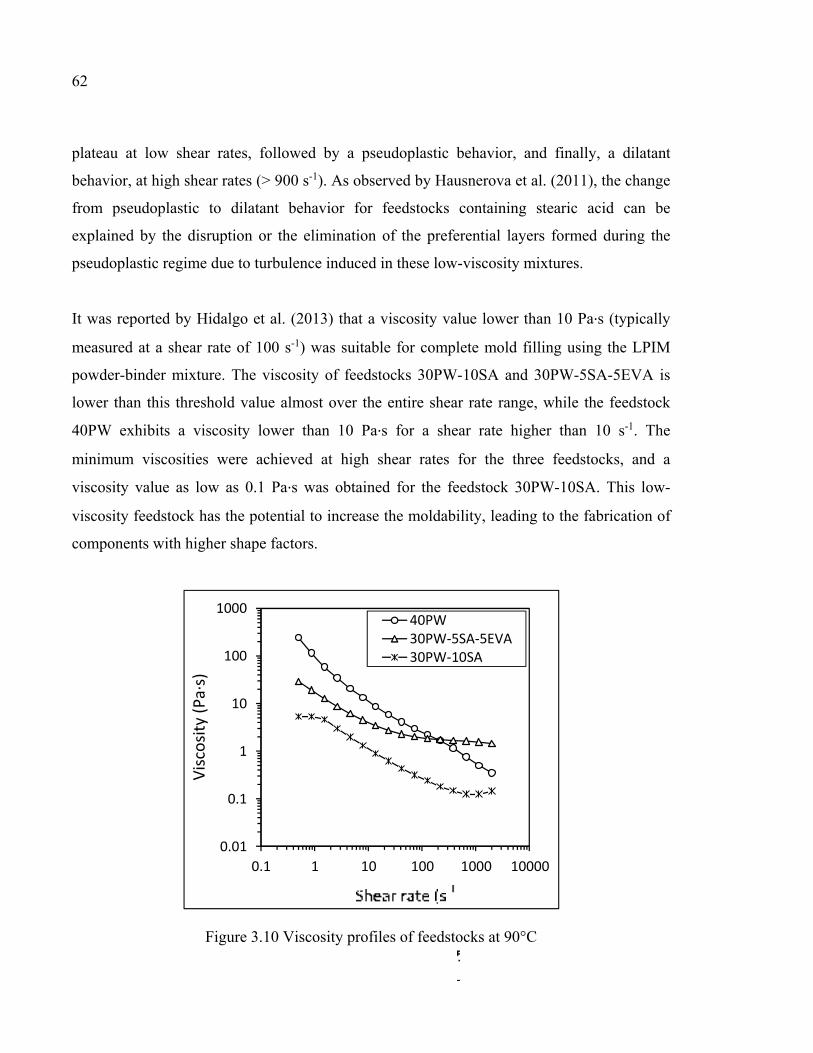
62
plateau at low shear rates, followed by a pseudoplastic behavior, and finally, a dilatant
behavior, at high shear rates (> 900 s-1). As observed by Hausnerova et al. (2011), the change
from pseudoplastic to dilatant behavior for feedstocks containing stearic acid can be
explained by the disruption or the elimination of the preferential layers formed during the
pseudoplastic regime due to turbulence induced in these low-viscosity mixtures.
It was reported by Hidalgo et al. (2013) that a viscosity value lower than 10 Pa∙s (typically
measured at a shear rate of 100 s-1) was suitable for complete mold filling using the LPIM
powder-binder mixture. The viscosity of feedstocks 30PW-10SA and 30PW-5SA-5EVA is
lower than this threshold value almost over the entire shear rate range, while the feedstock
40PW exhibits a viscosity lower than 10 Pa∙s for a shear rate higher than 10 s-1. The
minimum viscosities were achieved at high shear rates for the three feedstocks, and a
viscosity value as low as 0.1 Pa∙s was obtained for the feedstock 30PW-10SA. This low-
viscosity feedstock has the potential to increase the moldability, leading to the fabrication of
components with higher shape factors.
Figure 3.10 Viscosity profiles of feedstocks at 90°C
0.01
0.1
1
10
100
1000
0.1 1 10 100 1000 10000
40PW30PW-5SA-5EVA30PW-10SA
Visc
osity
(Pa∙
s)
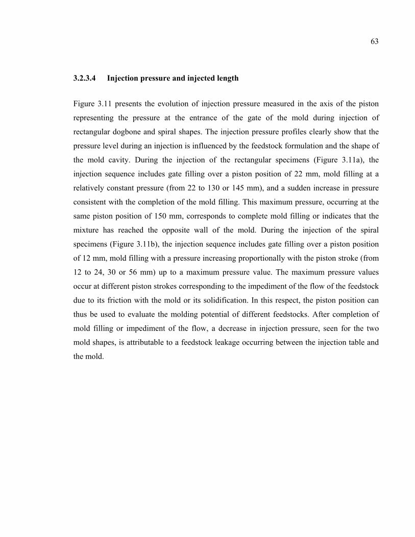
63
3.2.3.4 Injection pressure and injected length
Figure 3.11 presents the evolution of injection pressure measured in the axis of the piston
representing the pressure at the entrance of the gate of the mold during injection of
rectangular dogbone and spiral shapes. The injection pressure profiles clearly show that the
pressure level during an injection is influenced by the feedstock formulation and the shape of
the mold cavity. During the injection of the rectangular specimens (Figure 3.11a), the
injection sequence includes gate filling over a piston position of 22 mm, mold filling at a
relatively constant pressure (from 22 to 130 or 145 mm), and a sudden increase in pressure
consistent with the completion of the mold filling. This maximum pressure, occurring at the
same piston position of 150 mm, corresponds to complete mold filling or indicates that the
mixture has reached the opposite wall of the mold. During the injection of the spiral
specimens (Figure 3.11b), the injection sequence includes gate filling over a piston position
of 12 mm, mold filling with a pressure increasing proportionally with the piston stroke (from
12 to 24, 30 or 56 mm) up to a maximum pressure value. The maximum pressure values
occur at different piston strokes corresponding to the impediment of the flow of the feedstock
due to its friction with the mold or its solidification. In this respect, the piston position can
thus be used to evaluate the molding potential of different feedstocks. After completion of
mold filling or impediment of the flow, a decrease in injection pressure, seen for the two
mold shapes, is attributable to a feedstock leakage occurring between the injection table and
the mold.
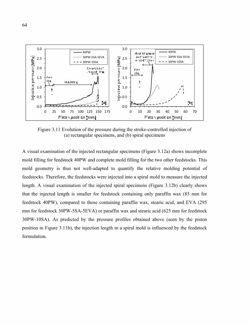
64
Figure 3.11 Evolution of the pressure during the stroke-controlled injection of (a) rectangular specimens, and (b) spiral specimens
A visual examination of the injected rectangular specimens (Figure 3.12a) shows incomplete
mold filling for feedstock 40PW and complete mold filling for the two other feedstocks. This
mold geometry is thus not well-adapted to quantify the relative molding potential of
feedstocks. Therefore, the feedstocks were injected into a spiral mold to measure the injected
length. A visual examination of the injected spiral specimens (Figure 3.12b) clearly shows
that the injected length is smaller for feedstock containing only paraffin wax (85 mm for
feedstock 40PW), compared to those containing paraffin wax, stearic acid, and EVA (295
mm for feedstock 30PW-5SA-5EVA) or paraffin wax and stearic acid (625 mm for feedstock
30PW-10SA). As predicted by the pressure profiles obtained above (seen by the piston
position in Figure 3.11b), the injection length in a spiral mold is influenced by the feedstock
formulation.
0.0
0.5
1.0
1.5
2.0
2.5
3.0
0 25 50 75 100 125 150 175
40PW30PW-5SA-5EVA30PW-10SA
0.0
0.5
1.0
1.5
2.0
2.5
3.0
0 10 20 30 40 50 60 70
40PW30PW-5SA-5EVA30PW-10SA
65
Figure 3.12 Injected length of (a) rectangular specimens, and (b) spiral specimens
3.2.4 Discussion
During injection, an ideal feedstock should be easy to mold, while avoiding the separation of
powder and binder constituents. As described above, moldability and segregation are linked
to the rheological behavior of the feedstock. In general, an increase in feedstock moldability
occurs with a decrease in viscosity, and segregation is minimized with an increase in the
viscosity of the mixture. Realizing the full moldability potential of the LPIM process is thus
limited by the segregation that may occur in the commercial LPIM injection machine. So far,
injection concepts proposed in literature have required injection valves and an
interconnecting pipe in which trapped feedstock may segregate during the process dead time.
For this reason, the feedstocks currently used in LPIM require thickening agents to limit
segregation within the injection press. The injection concept developed in this study
eliminates the segregation possibilities within the machine without the use of thickening
agents. Therefore, this equipment is suitable for the injection of very low-viscosity
feedstocks, leading to an increase in the moldability of the feedstock, and consequently an
increase in the capacity to produce more complex-shaped components.
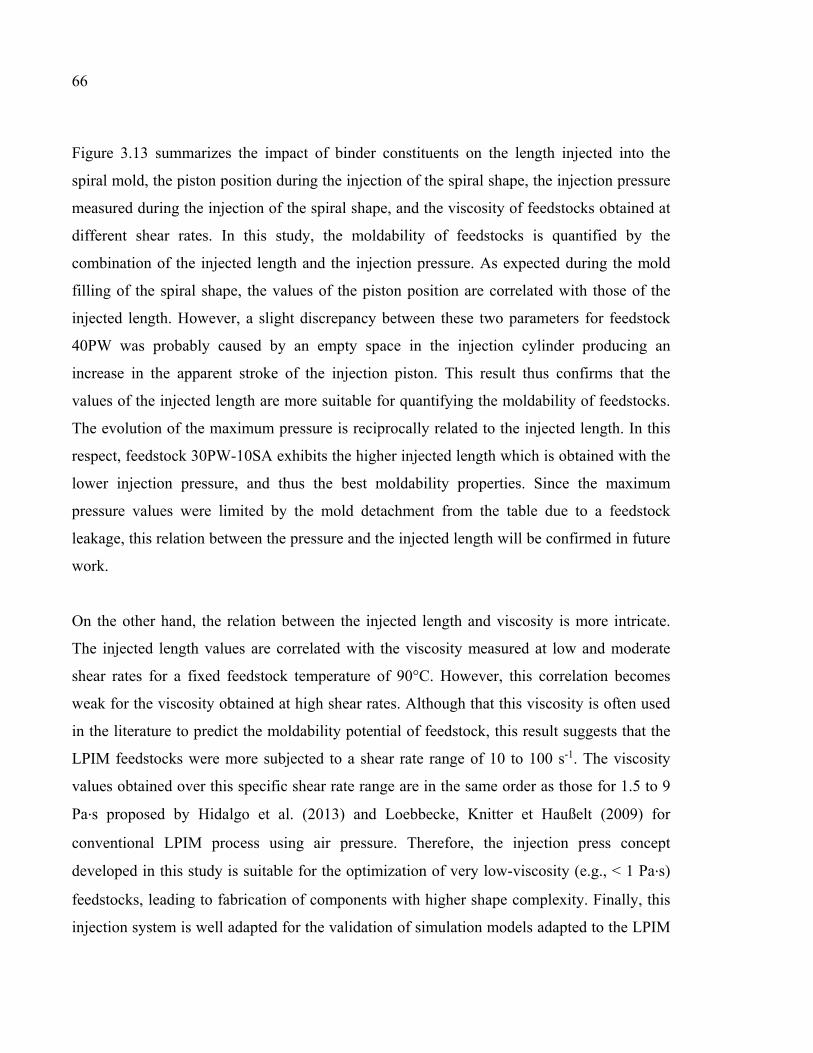
66
Figure 3.13 summarizes the impact of binder constituents on the length injected into the
spiral mold, the piston position during the injection of the spiral shape, the injection pressure
measured during the injection of the spiral shape, and the viscosity of feedstocks obtained at
different shear rates. In this study, the moldability of feedstocks is quantified by the
combination of the injected length and the injection pressure. As expected during the mold
filling of the spiral shape, the values of the piston position are correlated with those of the
injected length. However, a slight discrepancy between these two parameters for feedstock
40PW was probably caused by an empty space in the injection cylinder producing an
increase in the apparent stroke of the injection piston. This result thus confirms that the
values of the injected length are more suitable for quantifying the moldability of feedstocks.
The evolution of the maximum pressure is reciprocally related to the injected length. In this
respect, feedstock 30PW-10SA exhibits the higher injected length which is obtained with the
lower injection pressure, and thus the best moldability properties. Since the maximum
pressure values were limited by the mold detachment from the table due to a feedstock
leakage, this relation between the pressure and the injected length will be confirmed in future
work.
On the other hand, the relation between the injected length and viscosity is more intricate.
The injected length values are correlated with the viscosity measured at low and moderate
shear rates for a fixed feedstock temperature of 90°C. However, this correlation becomes
weak for the viscosity obtained at high shear rates. Although that this viscosity is often used
in the literature to predict the moldability potential of feedstock, this result suggests that the
LPIM feedstocks were more subjected to a shear rate range of 10 to 100 s-1. The viscosity
values obtained over this specific shear rate range are in the same order as those for 1.5 to 9
Pa∙s proposed by Hidalgo et al. (2013) and Loebbecke, Knitter et Haußelt (2009) for
conventional LPIM process using air pressure. Therefore, the injection press concept
developed in this study is suitable for the optimization of very low-viscosity (e.g., < 1 Pa∙s)
feedstocks, leading to fabrication of components with higher shape complexity. Finally, this
injection system is well adapted for the validation of simulation models adapted to the LPIM
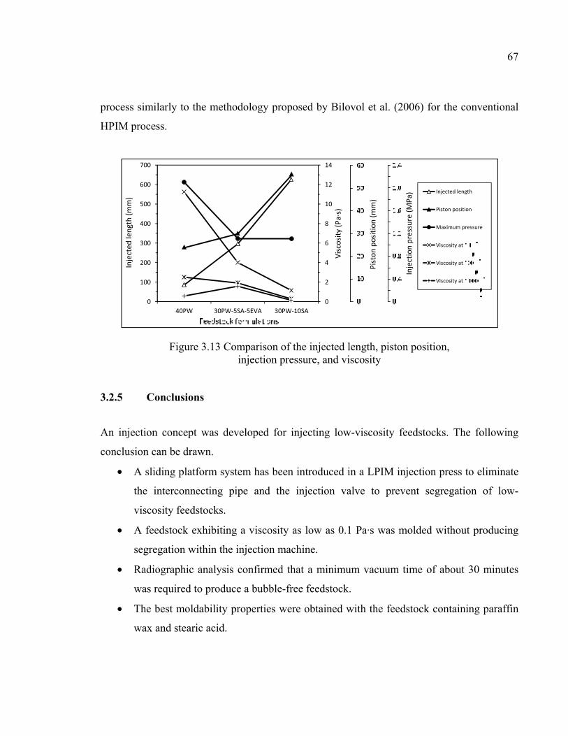
67
process similarly to the methodology proposed by Bilovol et al. (2006) for the conventional
HPIM process.
Figure 3.13 Comparison of the injected length, piston position, injection pressure, and viscosity
3.2.5 Conclusions
An injection concept was developed for injecting low-viscosity feedstocks. The following
conclusion can be drawn.
• A sliding platform system has been introduced in a LPIM injection press to eliminate
the interconnecting pipe and the injection valve to prevent segregation of low-
viscosity feedstocks.
• A feedstock exhibiting a viscosity as low as 0.1 Pa·s was molded without producing
segregation within the injection machine.
• Radiographic analysis confirmed that a minimum vacuum time of about 30 minutes
was required to produce a bubble-free feedstock.
• The best moldability properties were obtained with the feedstock containing paraffin
wax and stearic acid.
0
2
4
6
8
10
12
14
0
100
200
300
400
500
600
700
40PW 30PW-5SA-5EVA 30PW-10SA
Injected length
Piston position
Maximum pressure
Viscosity at 10 s-1
Viscosity at 100 s-1
Viscosity at 1 000 s-1
Inje
ctio
n pr
essu
re (M
Pa)
Visc
osity
(Pa∙
s)
Inje
cted
leng
th (m
m)
Pist
on p
ositi
on (m
m)

68
Acknowledgements:
This work was carried out with the financial support of the Natural Science and Engineering
Research Council (NSERC) of Canada and the financial support of École de technologie
supérieure internal funds (PSIRE-R fund and Lab equipment fund). The authors wish to
thank Mr. F. Fareh and Mr. A. Trad for their collaboration in TGA testing.
CONCLUSION
L’étude de l’aptitude au moulage des mélanges de très faible viscosité (0.1 Pa·s) lors de
l’injection est difficile à réaliser avec les machines commerciales, en raison du fort potentiel
de ségrégation dans les conduits d’injection lors des temps morts du procédé. Pour éviter ce
problème, une machine innovante a été développée et validée dans le cadre de ce projet. Au
départ, un piston d’injection puise un volume désiré de mélange d’un réservoir. Ensuite, un
mouvement latéral cisaille le mélange à l’intersection entre le réservoir et le cylindre et
bouche l’orifice de sortie du réservoir. Le cylindre est alors dégagé et peut recevoir le moule.
Suivant l’injection, le piston retourne à la position du réservoir et entre dans l’orifice de
sortie du réservoir. Le mélange résiduel est retourné dans le réservoir, mélangé et désaéré à
nouveau. Des essais de validation ont montré que la machine permet d’effectuer des
injections avec des mélanges à faible viscosité sans produire de ségrégation dans l’appareil
pendant les temps morts du procédé. Des essais d’injection ont montré que le mélange
30PW-10SA a parcouru la plus grande distance dans un moule de forme spirale, suivi du
mélange 30PW-5SA-5EVA et du mélange 40PW. Des essais de rhéologie ont corrélé ces
résultats pour une viscosité associée à un faible taux de cisaillement. Un essai de ségrégation
a montré qu’un temps d’attente de moins d’une minute devait être respecté avant de mesurer
une ségrégation significative sur un mélange à très faible viscosité. De plus, le
fonctionnement du système de vacuum a été validé par des analyses radiographiques. Un
temps de mélange sous vacuum de 30 minutes est suffisant pour éliminer complètement la
présence de bulles d’air dans la pièce injectée. Ces résultats montrent que cette machine rend
possible l’injection de mélanges peu visqueux augmentant l’aptitude au moulage de pièces de
forme complexe.
Quelques améliorations pourraient être effectuées sur la machine afin d’évaluer l’effet des
divers paramètres lors de l’injection. En ce moment, l’injection se fait à vitesse constante,
limitée par l’actuateur électrique actuellement utilisé. Celui-ci pourrait être remplacé par un
actuateur plus performant, pour évaluer l’effet de la vitesse d’injection ou pour injecter à
pression constante, c’est-à-dire faire varier la vitesse d’injection pour maintenir la pression.

ANNEXE I
CAHIER DES CHARGES
INTRODUCTION
Le moulage par injection est une technique très employée pour mettre en forme des pièces en
plastique. Ce procédé à l’avantage de mettre en forme des pièces complexes à faible coût,
pour de grandes productions. Le procédé de moulage par injection des poudres bénéficie
donc des mêmes avantages. La grande viscosité des mélanges de poudre et de liant oblige
l’utilisation de la haute pression d’injection. Toutefois, certains mélanges à basse viscosité
peuvent être injectés à basse pression.
L’injection à basse pression de poudre métallique à l’avantage par rapport à la basse pression
au niveau des coûts plus bas de la machine et de l’outillage. Cependant, le moulage est plus
difficile à réaliser, puisque moins de force est appliquée pour remplir le moule.
Ce cahier des charges décrit en détail les éléments nécessaires à la conception d’une machine
à injection basse pression de poudre métallique. La machine doit être adaptée
particulièrement aux besoins de la recherche pour valider des hypothèses et pour valider des
modèles d’injection qui tiennent en compte tous les paramètres d’injection.
Le cahier comprend la description d’une machine à injection basse pression de poudre
métallique, l’objectif corporatif, la définition du marché des machines d’injection et de
production de pièces et les clients. Ces éléments permettent ensuite l’analyse fonctionnelle
du besoin, qui découpe en détail les fonctions que doit remplir la machine.
72
1 DESCRIPTION DU PRODUIT
1.1 Objectifs
L’objectif est de concevoir, fabriquer et valider une presse à injection basse pression de
poudre métallique (LPIM). Cet équipement servira de banc d’essai en laboratoire. Il sera
utilisé par des étudiants chercheurs dans le but de valider des hypothèses et de valider des
modèles d’injection LPIM qui tiennent en compte tous les paramètres d’injection.
L’équipement doit être adaptable aux fins de recherches. Il doit être équipé de tous les
capteurs nécessaires à l’étude du procédé. Par exemple, il doit être muni de capteurs de
température et de pression. Le délai pour l’ensemble du projet est de 20 mois. Le budget
alloué à la fabrication de l’équipement n’est pas établi.
La machine doit être une amélioration des quelques machines existantes, présentées à la
section 3.1. Les améliorations à apporter sont :
• adapter la machine aux besoins de la recherche, tels que des capteurs multiples et un
volume de mélange faible;
• minimiser les zones où le mélange n’est pas en mouvement, notamment les conduits
d’alimentation, afin d’éviter la ségrégation;
• avoir un contrôle de la pression d’injection progressif;
• être nettoyable facilement et rapidement;
• être moins dispendieuse que les machines offertes sur le marché;
• atteindre une pression d’injection minimale de 0,7 MPa.
1.2 Livrables
Le livrable principal est une machine à injection basse pression de poudre métallique. Il doit
être démontré que la machine est fonctionnelle. Il y a trois éléments à valider, soit la réponse
des contrôles, la justesse de capteurs et les résultats de l’injection.
1.2.1 Validation des contrôles
Cette validation doit assurer que chaque contrôle de la machine est fonctionnel. Par exemple,
vérifier si les arrêts d’urgence sont fonctionnels peu importe la séquence.
73
1.2.2 Validation des capteurs
Cette validation doit vérifier que les capteurs sont bien étalonnés et sinon ajustés en
conséquence. Par exemple, vérifier que les capteurs de température indiquent la température
ambiante lorsque la machine est inactive.
1.2.3 Validation de l’injection
Pour la validation de l’injection, la norme ASTM B883-10 (ASTM, 2010) propose des
méthodes d’évaluation des pièces moulées :
• Production d’échantillons pour des essais de traction à température ambiante selon la
norme ASTM E8 (ASTM, 2013b). Les données qui peuvent être déduites de ces
essais sont :
o Limite d’élasticité, la résistance à la traction, l’allongement et la striction.
La littérature propose d’autres méthodes de validation :
• Selon Mangels (1994), les pièces produites peuvent être évaluées par des inspections
non destructives. Chaque état est inspecté (l’état vert, l’état brun et l’état fritté) par
des :
o Mesures de la masse et de la densité (par exemple, principe d’Archimède)
selon la norme ASTM B311-13 (ASTM, 2013a). Si la masse de l’échantillon
augmente dans l’eau, la norme ASTM B962-14 devient applicable (ASTM,
2014);
o Inspections au microscope pour déceler la présence de fissures de surface.
Inspection aux rayons X pour déceler des vides internes (nombre de défauts
par pièce);
o Mesures dimensionnelles.
• Ikegami et Purquerio (2001) mesurent la dureté de leurs échantillons;
• Medvedovski et Peltsman (2012) évaluent l’effet de la pression d’injection, de la
vitesse d’injection, de la température du mélange et du gradient de température (entre
la température du moule et la température du mélange) sur la densité de la pièce
moulée.
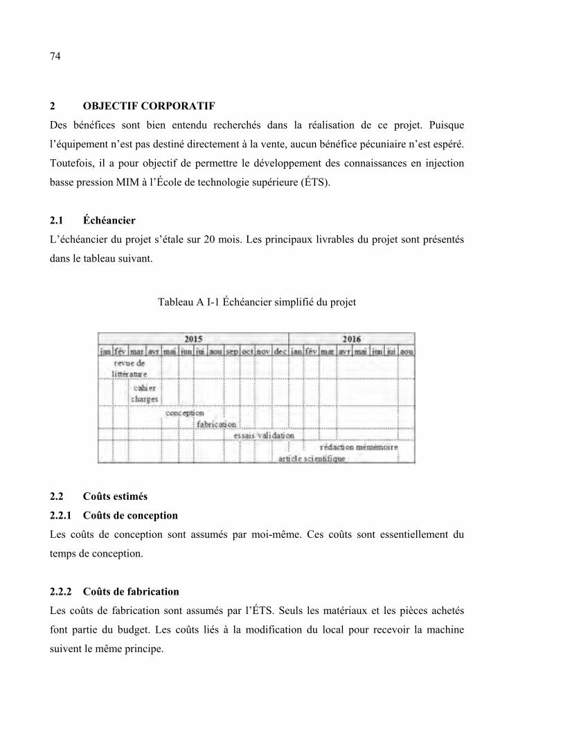
74
2 OBJECTIF CORPORATIF
Des bénéfices sont bien entendu recherchés dans la réalisation de ce projet. Puisque
l’équipement n’est pas destiné directement à la vente, aucun bénéfice pécuniaire n’est espéré.
Toutefois, il a pour objectif de permettre le développement des connaissances en injection
basse pression MIM à l’École de technologie supérieure (ÉTS).
2.1 Échéancier
L’échéancier du projet s’étale sur 20 mois. Les principaux livrables du projet sont présentés
dans le tableau suivant.
Tableau A I-1 Échéancier simplifié du projet
2.2 Coûts estimés
2.2.1 Coûts de conception
Les coûts de conception sont assumés par moi-même. Ces coûts sont essentiellement du
temps de conception.
2.2.2 Coûts de fabrication
Les coûts de fabrication sont assumés par l’ÉTS. Seuls les matériaux et les pièces achetés
font partie du budget. Les coûts liés à la modification du local pour recevoir la machine
suivent le même principe.
75
2.2.3 Coûts des essais
Des coûts sont à prévoir pour la validation et les essais. De la poudre et du liant devront être
achetés. Les détails sur les matériaux à utiliser seront déterminés en temps et lieu.
2.3 Degré d’innovation
Cette machine n’est pas conçue comme une machine industrielle. Il s’agit d’un prototype et
d’un article de démonstration de concept qui sera amélioré en cours d’utilisation. La machine
répond à un besoin universitaire tout en apportant des variantes aux machines existantes (voir
section 1.1).
2.4 Confidentialité
L’équipement livré n’est soumis à aucune politique de confidentialité ni aucune entente
contractuelle. Le développement est fait dans le cadre d’un projet de recherche étudiant qui
est libre d’être divulgué en accord avec les droits d’auteurs. Il n’est pas prévu à ce stade de
déposer un brevet concernant cette machine. L’équipement ne fait pas partie de la liste du
Programme des Marchandises Contrôlées du Canada.
3 DÉFINITION DU MARCHÉ
3.1 Primaire
Le marché des machines à injection pour le procédé des poudres est principalement
représenté par la technologie d’injection à haute pression. Ce type de machine est issu des
machines d’injection de plastique.
Les machines fonctionnant à basse pression sont moins présentes sur le marché. C’est le
créneau visé par ce projet. Le principal fabricant de machines LPIM est Peltsman. La
différence majeure entre les machines HPIM et LPIM est la méthode de transport de le
mélange vers le moule. Les machines HPIM utilisent une vise piston, tandis que les machines
LPIM utilisent simplement la pression d’air.
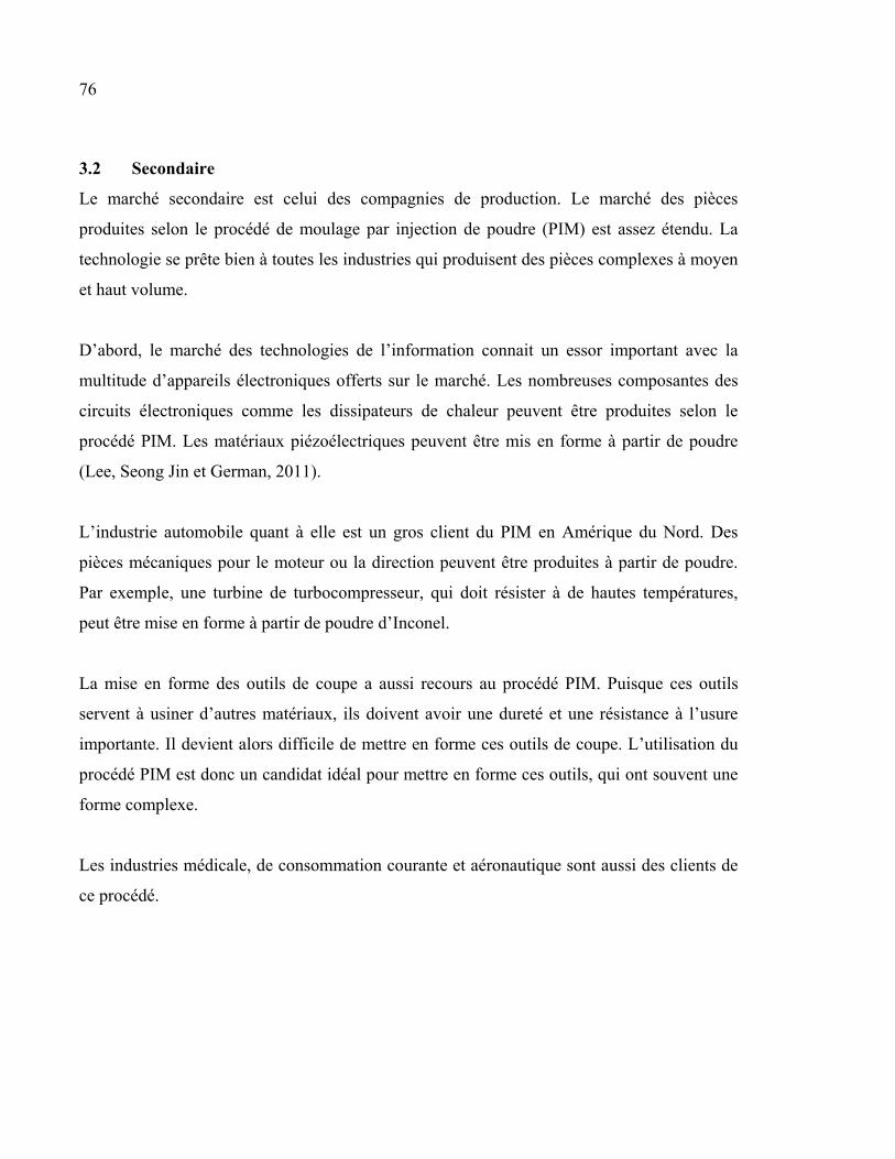
76
3.2 Secondaire
Le marché secondaire est celui des compagnies de production. Le marché des pièces
produites selon le procédé de moulage par injection de poudre (PIM) est assez étendu. La
technologie se prête bien à toutes les industries qui produisent des pièces complexes à moyen
et haut volume.
D’abord, le marché des technologies de l’information connait un essor important avec la
multitude d’appareils électroniques offerts sur le marché. Les nombreuses composantes des
circuits électroniques comme les dissipateurs de chaleur peuvent être produites selon le
procédé PIM. Les matériaux piézoélectriques peuvent être mis en forme à partir de poudre
(Lee, Seong Jin et German, 2011).
L’industrie automobile quant à elle est un gros client du PIM en Amérique du Nord. Des
pièces mécaniques pour le moteur ou la direction peuvent être produites à partir de poudre.
Par exemple, une turbine de turbocompresseur, qui doit résister à de hautes températures,
peut être mise en forme à partir de poudre d’Inconel.
La mise en forme des outils de coupe a aussi recours au procédé PIM. Puisque ces outils
servent à usiner d’autres matériaux, ils doivent avoir une dureté et une résistance à l’usure
importante. Il devient alors difficile de mettre en forme ces outils de coupe. L’utilisation du
procédé PIM est donc un candidat idéal pour mettre en forme ces outils, qui ont souvent une
forme complexe.
Les industries médicale, de consommation courante et aéronautique sont aussi des clients de
ce procédé.
77
4 CLIENTS
4.1 Internes
Les clients internes sont les étudiants et les chercheurs de l’École de technologie supérieure
(ÉTS) qui utiliseront cet équipement afin de valider leurs théories en lien avec le procédé
LPIM. L’ÉTS est l’investisseur dans ce projet.
4.2 Externes
Les clients externes sont d’abord représentés par l’industrie en général. L’équipement offrira
aux compagnies une méthode de fabrication alternative pour la production de pièces
complexes de moyenne à haute production à des coûts avantageux. Les coûts avantageux
sont dus à la simplicité du fonctionnement de la machine et à la taille relativement faible du
moule d’injection, comparativement au procédé d’injection à haute pression (HPIM). Les
clubs étudiants de l’ÉTS sont des clients potentiels au même titre que l’industrie.
5 PROCESSUS D’ANALYSE DU BESOIN
Ce processus suit la méthode suggérée par Bernard Bouissières (2008) énoncée dans son
livre « Expression du besoin et cahier des charges fonctionnel ».
5.1 Définition du besoin
5.1.1 Système englobant
Une machine LP-MIM est utilisée dans un contexte de production de pièces dont la forme est
très complexe (Goncalves, 2001). La production se divise en 4 étapes montrées à la Figure-A
I-1, soit la préparation du mélange, l’injection, le déliantage et le frittage. La machine LPIM
est une constituante dans le processus de mise en forme. Elle est responsable des deux
premières étapes.
78
Figure-A I-1 Étapes du procédé MIM
5.1.2 Besoin essentiel
Le besoin essentiel de l’utilisateur est de mettre en forme des pièces à partir de poudre
métallique dans l’intention d’obtenir des données permettant d’étudier le procédé. Il en
découle deux besoins, soit :
• le mélange des constituants;
• l’injection du mélange dans la cavité d’un moule.
5.1.3 Concept associé
Le demandeur impose la réponse au besoin essentiel énoncé ci-haut. La mise en forme doit se
faire par l’injection d’un mélange de poudre métallique et de liant dans un moule en utilisant
de la basse pression (LPIM). La basse pression est définie par Goncalves (2001) entre 0 et
0,7 MPa.
Le principal avantage du procédé PIM est qu’il combine la facilité de mise en forme de
pièces complexes du procédé d’injection de plastique à la haute résistance thermique et
mécanique des métaux. Les coûts de mise en forme sont donc relativement faibles dans le cas
de production à moyen et haut volume. De plus, il est possible de réutiliser les résidus dans
79
les canaux d’injection, ce qui est notamment avantageux pour les matériaux dispendieux
(Vervoort, Vetter et Duszczyk, 1996). Pour un même matériau, les propriétés mécaniques
sont supérieures aux procédés de moulage de fonderie, mais inférieures à une pièce corroyée
(Heaney, 2012).
L’injection à basse pression est avantageuse puisque les moules sont moins massifs, le
déplacement du mélange fondu est laminaire et les fissures de surfaces sont moindres en
raison de la faible contrainte appliquée (Mangels, 1994).
5.1.4 Analyse et validation du besoin
Les questions posées ci-après sont tirées du livre de Bernard Bouissières (2008).
Qui précisément est le porteur de ce besoin et que recherche-t-il?
Le porteur du besoin est représenté par les clients internes et externes, présentés au chapitre
4.
Dans quelles circonstances ressent-il ce besoin?
Les clients internes utiliseront cet équipement afin de valider leurs théories en lien avec le
procédé LPIM. Pour les clients externes, l’équipement leur offrira une méthode de
fabrication alternative pour la production de pièces complexes de moyenne à haute
production à des coûts avantageux. Ces coûts sont dus à la simplicité du fonctionnement de la
machine et à la taille relativement faible du moule d’injection, comparativement au procédé
d’injection à haute pression (HPIM).
Quelles sont les raisons de ce besoin, dans quel but est-il à satisfaire?
La raison de ce besoin est de mettre en forme des pièces moulées sans défauts. Les défauts
sont :
• Mauvaises dimensions dues à un rétrécissement après frittage non constant d’une
pièce à l’autre. Ce rétrécissement non uniforme est le résultat d’un mélange ayant
80
subi de la ségrégation ou ayant des différences dans la distribution de la taille des
particules d’un lot de poudre à l’autre (D10, D50 et D90);
• Gauchissements dus au refroidissement non uniforme de la pièce dans le moule (Ahn
et al., 2008);
• Remplissages incomplets dus à un contrôle de la température non adéquat
(températures du mélange, du conduit d’alimentation et/ou du moule) ou
l’emprisonnement de poches d’air dans une partie du moule;
• Imperfections de surface dues au phénomène de détente rapide dans le moule
(Dvorak, Barriere et Gelin, 2005);
• Vides internes dus à la présence de bulles d’air dans le mélange ou à l’accumulation
de liant à certains endroits.
Aussi, ce besoin s’exprime par le désir d’optimiser les paramètres tout en évitant les défauts
énoncés ci-haut. Par exemple :
• minimiser la quantité de liant;
• minimiser le temps de préparation du mélange;
• minimiser le temps de cycle;
• minimiser les pertes.
Quelles sont les causes de ce besoin?
Le moulage par injection basse pression n’est pas un procédé parfait. La variation des
paramètres du procédé, comme la proportion de liant dans le mélange ou la pression
d’injection ont des effets sur la réussite ou non de la mise en forme.
Quelle est la nécessité de ce besoin, son importance, la valeur attachée par le ou les porteurs
à sa satisfaction?
Pour économiser du temps de montage par essai-erreur, les clients internes veulent pouvoir
prévoir l’effet de la variation des paramètres du procédé par des modèles. La machine va
servir à valider ces modèles.
81
Quelle est la solvabilité des porteurs de ce besoin?
Cette demande des clients internes est solvable puisqu’elle se base sur des comparables. Par
exemple, Gelin, Barriere et Dutilly (1999) ont produit un modèle par éléments finis qu’ils ont
ensuite comparés à des essais sur une machine HPIM. Ahn et al. (2008) ont développé un
modèle d’injection et de refroidissement qu’ils ont aussi comparés à des essais sur une
machine HPIM
Un principe de fonctionnement, une voie technique ont-ils été choisis a priori?
Un principe de fonctionnement est imposé par les clients internes, tel que présenté à la
section 5.1.4.
Quelles sont les possibilités de disparition ou d’évolution du besoin à satisfaire?
L’industrie est toujours en quête des moyens de fabrications les plus rentables. La mise en
forme de matériaux de plus en plus exotique va augmenter afin de satisfaire les besoins
précis de l’industrie. Puisque ces matériaux sont dispendieux, il faut éviter les pertes.
La conception de machine LPIM commence avec Peltsman (1986). Ensuite, Sack et
Lietzmann (1990) proposent une étude sur l’essai du moulage par injection basse pression de
poudre métallique. Mangels (1994) présente quant à lui une étude sur l’effet des différents
paramètres pour le moulage de poudre de céramique avec une machine Peltsman. Goncalves
(2001) présente la conception d’une machine à injection basse pression fonctionnant selon le
même principe que Peltsman. Ikegami et Purquerio (2001) utilisent la machine de Gonçalves
pour produire des pièces d’essai de traction. Rei et al. (2002), Medvedovski et Peltsman
(2012), Gerl et al. (2009) et Liu (1999) utilisent tous la machine Peltsman pour le moulage
lors de leurs essais. Donc, la littérature présente deux machines LPIM, soit la machine
Peltsman et la machine de Gonçalves, qui n’est pas commercialisée.
La concurrence au niveau des machines LPIM est faible, le seul joueur étant la compagnie
Peltsman. Le descriptif de ces machines est présenté à la section 3.1.
82
Une technique de remplacement au procédé LPIM est la fabrication additive. Ce procédé est
encore jeune et il est plus adapté à la production de petites et moyennes séries (Atzeni et
Salmi, 2012).
Diagnostic :
Le besoin est validé. Cependant, il faut s’assurer qu’elle possède tous les instruments de
mesure adéquats pour l’étude du procédé.
5.1.5 Caractérisation du besoin
L’équipement (une machine) doit être livré au client pour août 2016. Cela comprend :
• la conception détaillée :
o dessins d’assemblage et de détail;
o analyse de contraintes;
o analyse de risques;
o guide d’utilisation;
o programme d’acquisition des données.
• la fabrication;
• l’installation;
• la validation et la production d’un article scientifique.
La machine doit comprendre une section mélangeur, une section injection et une section
moule. La préparation du mélange doit se faire pour de petites quantités, soit maximum 1 kg
pour diminuer le coût des essais. Le mélange doit se faire sous vide à température maximale
de 130 °C. Il doit y avoir un contrôle de la température à maximum ± 2 °C, du mélangeur
jusqu’au moule. La pression d’injection doit être de maximum 1,0 MPa. Si la pression d’air
est utilisée, une pression maximale de 0,7 MPa est acceptable. L’application de la pression
doit se faire de manière progressive. La machine doit mettre en forme des échantillons de
traction plats et cylindriques. Les dimensions de la base de moule doivent être de 6 po par 12
po. Les moules pourront cependant être plus petits, en fonction de la pièce à mouler. La
machine doit faire l’acquisition de la température du mélange dans le mélangeur, du bol, du
83
conduit d’alimentation et du moule. La pression dans le mélangeur et la pression dans le
moule doivent être mesurées. Les paramètres du mélangeur, tels que les vitesses de rotation,
doivent être contrôlables. Le nettoyage de la machine doit être facile et rapide. Aucun résidu
ne doit demeurer en place. Le nettoyage se fait généralement en démontant la machine et en
raclant les surfaces. La machine sera utilisée dans un environnement de laboratoire. Elle doit
donc côtoyer respectueusement les autres machines et les individus qui les utilisent. De plus,
elle doit passer dans une porte de dimension standard.
5.2 Cycle de vie du produit
Le cycle de vie est composé de trois étapes.
5.2.1 Phase avant exploitation
Cette phase consiste d’abord par l’installation de la machine sur place.
5.2.2 Phase exploitation
La première phase d’exploitation est la validation de la machine. Elle se fera telle qu’énoncée
à la section 1.2. Ensuite, la phase d’utilisation de la machine se fera avec différents moules,
selon les besoins de l’utilisateur. Cette phase se caractérise par le fonctionnement, mais aussi
par de longues périodes d’inactivités. La phase de maintenance est en fait liée à la phase
d’utilisation. La machine sera nettoyée pour éliminer les résidus après l’utilisation. Au niveau
du fonctionnement mécanique, la maintenance doit être minimum. Une phase d’amélioration
est à prévoir, puisque la machine sera adaptée aux besoins du moment. Dans ce cas, une
nouvelle phase de validation est nécessaire. Pour les situations exceptionnelles, la machine
doit être munie des éléments d’arrêts selon les normes en vigueur.
5.2.3 Phase après exploitation
Le retrait de la machine se fera lorsque les besoins des utilisateurs ne pourront plus être
comblés ni par la machine ni par des modifications apportées à celle-ci. Les composantes de
la machine pourront être recyclées. Le tableau suivant montre chaque situation durant le
cycle de vie de l’équipement.
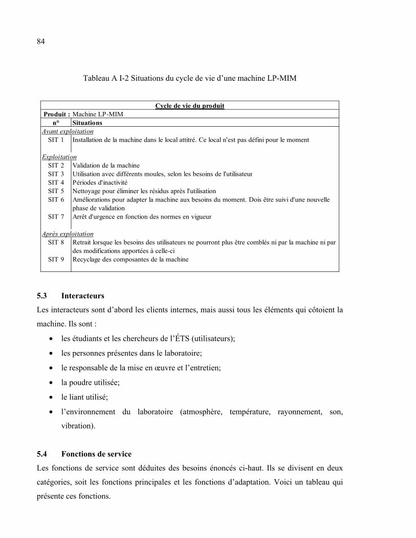
84
Tableau A I-2 Situations du cycle de vie d’une machine LP-MIM
Produit : Machine LP-MIMn° Situations
SIT 1 Installation de la machine dans le local attitré. Ce local n'est pas défini pour le moment
SIT 2 Validation de la machineSIT 3 Utilisation avec différents moules, selon les besoins de l'utilisateurSIT 4 Périodes d'inactivitéSIT 5 Nettoyage pour éliminer les résidus après l'utilisationSIT 6 Améliorations pour adapter la machine aux besoins du moment. Dois être suivi d'une nouvelle
phase de validationSIT 7 Arrêt d'urgence en fonction des normes en vigueur
SIT 8 Retrait lorsque les besoins des utilisateurs ne pourront plus être comblés ni par la machine ni par des modifications apportées à celle-ci
SIT 9 Recyclage des composantes de la machine
Cycle de vie du produit
Avant exploitation
Exploitation
Après exploitation
5.3 Interacteurs
Les interacteurs sont d’abord les clients internes, mais aussi tous les éléments qui côtoient la
machine. Ils sont :
• les étudiants et les chercheurs de l’ÉTS (utilisateurs);
• les personnes présentes dans le laboratoire;
• le responsable de la mise en œuvre et l’entretien;
• la poudre utilisée;
• le liant utilisé;
• l’environnement du laboratoire (atmosphère, température, rayonnement, son,
vibration).
5.4 Fonctions de service
Les fonctions de service sont déduites des besoins énoncés ci-haut. Ils se divisent en deux
catégories, soit les fonctions principales et les fonctions d’adaptation. Voici un tableau qui
présente ces fonctions.
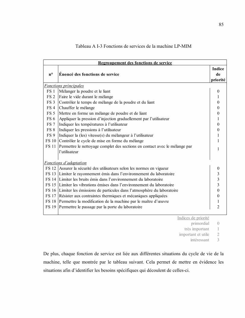
85
Tableau A I-3 Fonctions de services de la machine LP-MIM
n° Énoncé des fonctions de serviceIndice
de priorité
FS 1 Mélanger la poudre et le liant 0FS 2 Faire le vide durant le mélange 1FS 3 Contrôler le temps de mélange de la poudre et du liant 0FS 4 Chauffer le mélange 0FS 5 Mettre en forme un mélange de poudre et de liant 0FS 6 Appliquer la pression d’injection graduellement par l’utilisateur 1FS 7 Indiquer les températures à l’utilisateur 0FS 8 Indiquer les pressions à l’utilisateur 0FS 9 Indiquer la (les) vitesse(s) du mélangeur à l’utilisateur 1
FS 10 Contrôler le cycle de mise en forme du mélange 1FS 11 Permettre le nettoyage complet des sections en contact avec le mélange par
l’utilisateur1
FS 12 Assurer la sécurité des utilisateurs selon les normes en vigueur 0FS 13 Limiter le rayonnement émis dans l’environnement du laboratoire 3FS 14 Limiter les bruits émis dans l’environnement du laboratoire 3FS 15 Limiter les vibrations émises dans l’environnement du laboratoire 3FS 16 Limiter les émissions de particules dans l’atmosphère du laboratoire 0FS 17 Résister aux contraintes thermiques et mécaniques appliquées 0FS 18 Permettre la modification de la machine par le maître d’œuvre 1FS 19 Permettre le passage par la porte du laboratoire 2
Indices de prioritéprimordial 0
très important 1important et utile 2
intéressant 3
Fonctions principales
Fonctions d’adaptation
Regroupement des fonctions de service
De plus, chaque fonction de service est liée aux différentes situations du cycle de vie de la
machine, telle que montrée par le tableau suivant. Cela permet de mettre en évidence les
situations afin d’identifier les besoins spécifiques qui découlent de celles-ci.
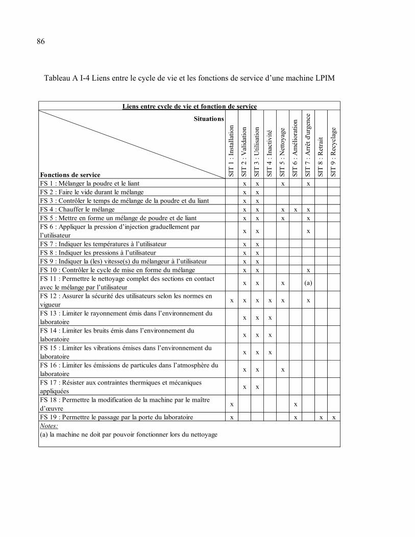
86
Tableau A I-4 Liens entre le cycle de vie et les fonctions de service d’une machine LPIM
Situations
Fonctions de serviceFS 1 : Mélanger la poudre et le liant x x x xFS 2 : Faire le vide durant le mélange x xFS 3 : Contrôler le temps de mélange de la poudre et du liant x xFS 4 : Chauffer le mélange x x x x xFS 5 : Mettre en forme un mélange de poudre et de liant x x x xFS 6 : Appliquer la pression d’injection graduellement par l’utilisateur
x x x
FS 7 : Indiquer les températures à l’utilisateur x xFS 8 : Indiquer les pressions à l’utilisateur x xFS 9 : Indiquer la (les) vitesse(s) du mélangeur à l’utilisateur x xFS 10 : Contrôler le cycle de mise en forme du mélange x x xFS 11 : Permettre le nettoyage complet des sections en contact avec le mélange par l’utilisateur
x x x (a)
FS 12 : Assurer la sécurité des utilisateurs selon les normes en vigueur
x x x x x x
FS 13 : Limiter le rayonnement émis dans l’environnement du laboratoire
x x x
FS 14 : Limiter les bruits émis dans l’environnement du laboratoire
x x x
FS 15 : Limiter les vibrations émises dans l’environnement du laboratoire
x x x
FS 16 : Limiter les émissions de particules dans l’atmosphère du laboratoire
x x x
FS 17 : Résister aux contraintes thermiques et mécaniques appliquées
x x
FS 18 : Permettre la modification de la machine par le maître d’œuvre
x x
FS 19 : Permettre le passage par la porte du laboratoire x x x x
(a) la machine ne doit par pouvoir fonctionner lors du nettoyage
SIT
7 :
Arr
êt d
'urg
ence
SIT
8 :
Ret
rait
SIT
9 :
Rec
ycla
ge
Liens entre cycle de vie et fonction de service
Notes:
SIT
3 :
Uti
lisat
ion
SIT
2 :
Val
idat
ion
SIT
1 :
Ins
talla
tion
SIT
4 :
Ina
ctiv
ité
SIT
5 :
Net
toya
ge
SIT
6 :
Am
élio
ratio
n
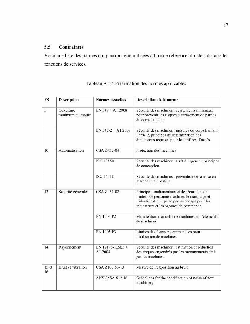
87
5.5 Contraintes
Voici une liste des normes qui pourront être utilisées à titre de référence afin de satisfaire les
fonctions de services.
Tableau A I-5 Présentation des normes applicables
FS Description Normes associées Description de la norme
5 Ouverture minimum du moule
EN 349 + A1 2008 Sécurité des machines : écartements minimaux pour prévenir les risques d’écrasement de parties du corps humain
EN 547-2 + A1 2008 Sécurité des machines : mesures du corps humain. Partie 2, principes de détermination des dimensions requises pour les orifices d’accès
10 Automatisation CSA Z432-04 Protection des machines
ISO 13850 Sécurité des machines : arrêt d’urgence : principes de conception.
ISO 14118 Sécurité des machines : prévention de la mise en marche intempestive
13 Sécurité générale CSA Z431-02 Principes fondamentaux et de sécurité pour l’interface personne-machine, le marquage et l’identification : principes de codage pour les indicateurs et les organes de commande
EN 1005 P2 Manutention manuelle de machines et d’éléments de machines
EN 1005 P3 Limites des forces recommandées pour l’utilisation de machines
14 Rayonnement EN 12198-1,2&3 + A1 2008
Sécurité des machines : estimation et réduction des risques engendrés par les rayonnements émis par les machines
15 et 16
Bruit et vibration CSA Z107.56-13 Mesure de l’exposition au bruit
ANSI/ASA S12.16 Guidelines for the specification of noise of new machinery
88
5.6 Limites et exclusions
• Le contrôle de la masse ne fait pas partie de l’équipement. La préparation des
constituants du mélange se fait séparément afin d’avoir une grande précision.
• La mesure du débit dans le conduit (si un conduit est nécessaire) n’est pas requise. La
présence d’un tel capteur pourrait nuire à l’écoulement.
• La valeur de la force résultante pour maintenir le moule fermé n’a pas à être mesurée.
• La consommation d’énergie n’est pas un critère important.
• Aucun mécanisme d’éjection n’est prévu.
• Le refroidissement du moule n’est pas inclus dans ce projet. Cependant, cet
équipement pourrait être ajouté dans le futur.
6 MAISON DE LA QUALITÉ
Cette maison de la qualité sert à déterminer l’importance relative de chaque critère
(colonnes). Il faut aussi considérer l’impact de chaque critère entre eux. On veut que la
pression d’injection soit la plus élevée, donc une augmentation des coûts. Il faut donc trouver
un compromis entre pression d’injection et coûts. La pression du vide doit être le maximum
possible, mais elle doit s’adapter à différents volumes tout en gardant la même efficacité. De
plus, une attention particulière doit être posée en lien avec le nettoyage, il faut éviter que la
pompe à vide aspire du mélange par exemple. La flexibilité du mélange est en lien avec la
dimension de la cavité du moule. De plus, la flexibilité peut engendrer des coûts
supplémentaires lors de l’acquisition de l’équipement. Cela sera toutefois compensé par des
coûts moindres lors des essais. Une température plus élevée risque de faire augmenter les
coûts, puisque les matériaux doivent résister à la chaleur. L’équipement pour atteindre des
températures plus élevées est aussi plus dispendieux. La maison de la qualité permet donc de
bâtir un barème d’évaluation pour juger les concepts qui seront générés.
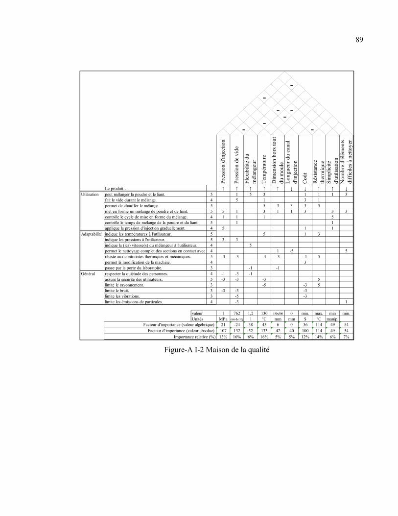
89
Figure-A I-2 Maison de la qualité
54554545544543453334
6% 7%Importance relative (%) 13% 16% 6% 16% 5% 5% 12% 14%
49 54
Facteur d'importance (valeur absolue) 107 132 52 133 42 40 100 114 49 54
Facteur d'importance (valeur algébrique) 21 -24 38 43 6 0 36 114
min min.Unités MPa mm de Hg l °C mm mm $ °C manip.valeur 1 762 1,2 130 150x300 0 min. max.
assure la sécurité des utilisateurs.limite le rayonnement.limite le bruit.limite les vibrations.
-3
Utilisation
Adaptabilité
Général respecter la quiétude des personnes. -1 -3 -1
limite les émissions de particules. -3-5
-3 -3
1
5
3
3
Nom
bre
d'él
émen
ts
diff
icile
s à
netto
yer
↓
-
15
-3
-3 55
3permet la modification de la machine.
-5-3 -3 -3
passe par la porte du laboratoire. -1 -1
résiste aux contraintes thermiques et mécaniques. -3 -3 -3 -3 -1 5permet le nettoyage complet des sections en contact avec 1 -5indique la (les) vitesse(s) du mélangeur à l'utilisateur. 5indique les pressions à l'utilisateur. 3 3
1 1indique les températures à l'utilisateur. 5applique la pression d'injection graduellement. 5
1 3
contrôle le temps de mélange de la poudre et du liant. 1
1 3permet de chauffer le mélange. 5 3
3contrôle le cycle de mise en forme du mélange. 1 1 1
3 3 5met en forme un mélange de poudre et de liant. 5 1 3 1
fait le vide durant le mélange. 5 1 3 1
↓ ↓ ↑ ↑peut mélanger la poudre et le liant. 1 5 3Le produit… ↑ ↑ ↑ ↑ ↑
1 1 1
Pre
ssio
n d'
inje
ctio
n
Pre
ssio
n de
vid
e
Fle
xibi
lité
du
mél
ange
ur
Tem
péra
ture
Dim
ensi
on h
ors
tout
du
mou
leL
ongu
eur
du c
anal
d'
inje
ctio
n
Coû
t
Rés
ista
nce
ther
miq
ueS
impl
icité
d'
utili
satio
n
- --
-
-- -
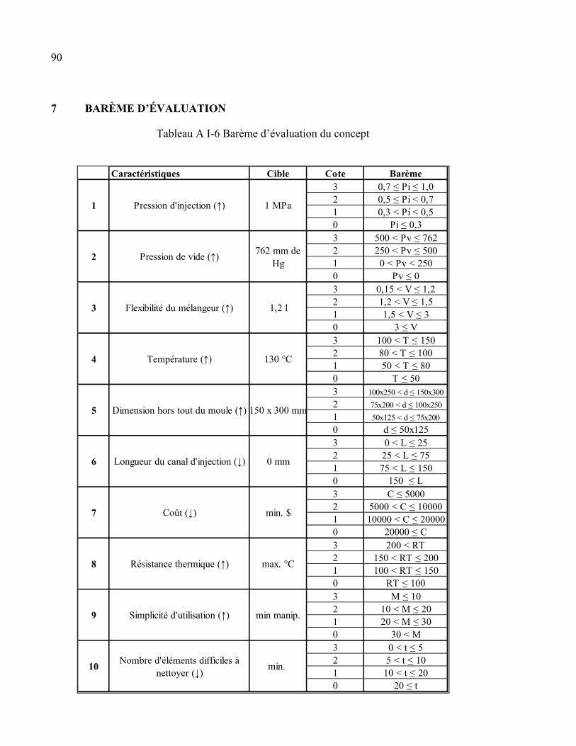
90
7 BARÈME D’ÉVALUATION
Tableau A I-6 Barème d’évaluation du concept
Caractéristiques Cible Cote Barème3 0,7 ≤ Pi ≤ 1,02 0,5 ≤ Pi < 0,71 0,3 < Pi < 0,50 Pi ≤ 0,33 500 < Pv ≤ 7622 250 < Pv ≤ 5001 0 < Pv < 2500 Pv ≤ 03 0,15 < V ≤ 1,22 1,2 < V ≤ 1,51 1,5 < V ≤ 30 3 ≤ V3 100 < T ≤ 1502 80 < T ≤ 1001 50 < T ≤ 800 T ≤ 503 100x250 < d ≤ 150x300
2 75x200 < d ≤ 100x250
1 50x125 < d ≤ 75x200
0 d ≤ 50x1253 0 < L ≤ 252 25 < L ≤ 751 75 < L ≤ 1500 150 ≤ L3 C ≤ 50002 5000 < C ≤ 100001 10000 < C ≤ 200000 20000 ≤ C3 200 < RT2 150 < RT ≤ 2001 100 < RT ≤ 1500 RT ≤ 1003 M ≤ 102 10 < M ≤ 201 20 < M ≤ 300 30 < M3 0 < t ≤ 52 5 < t ≤ 101 10 < t ≤ 200 20 ≤ t
1 Pression d'injection (↑) 1 MPa
2 Pression de vide (↑)762 mm de
Hg
3 Flexibilité du mélangeur (↑) 1,2 l
4 Température (↑) 130 °C
5 Dimension hors tout du moule (↑) 150 x 300 mm
6 Longueur du canal d'injection (↓) 0 mm
7 Coût (↓) min. $
8 Résistance thermique (↑) max. °C
9 Simplicité d'utilisation (↑) min manip.
10Nombre d'éléments difficiles à
nettoyer (↓)min.

91
CONCLUSION
Ce cahier des charges présente l’analyse complète des besoins du client, pour la conception,
la fabrication et la validation d’une presse pour le procédé d’injection à basse pression de
poudres métallique.
Les besoins sont définis afin de déterminer les spécifications techniques. Une maison de la
qualité est ensuite construite afin de définir le poids de chaque spécification. Finalement, un
barème d’évaluation des spécifications est bâti afin d’évaluer les concepts à venir.

ANNEXE II
A LOW-PRESSURE POWDER INJECTION MOLDING MACHINE AND METHOD
Cette annexe présente les pages préliminaires ainsi que les revendications de la demande de
brevet provisoire aux État-Unis déposée le 29 avril 2016 portant le numéro de dépôt
62/329,419.
Inventeurs : Vincent Demers, Simon G. Lamarre et Jean-François Châtelain
Cessionnaire : École de technologie supérieure
CROSS-REFERENCE TO RELATED APPLICATIONS
[0001] This is the first application filed for the present invention.
TECHNICAL FIELD
[0002] The present invention relates to the field of low-pressure powder injection molding,
and more specifically to low-pressure powder injection molding machines and methods.
BACKGROUND
[0003] High-pressure powder injection molding (HPIM) is a manufacturing process
consisting in mixing metallic or ceramic powder with a molten polymeric binder to obtain a
feedstock which is injected at high pressure into a mold cavity to generate a complex shape.
Reciprocating screw molding machine is generally used to reach the high pressure required
in conventional power injection molding (PIM). During debinding and sintering treatments,
the binder is completely removed to obtain a near-net shape dense metallic component. Key
features of HPIM process are low production costs, shape complexity, tight tolerances,
applicability to several materials, and high final properties.
[0004] Low-pressure powder injection molding (LPIM) is a variant of the conventional
HPIM process in which recent progress in feedstock formulations has generated new
opportunities for producing shapes of higher complexity that is yet cost-effective, either in
94
high or in low production volumes. A pneumatic molding machine is generally used to fill a
mold cavity with a powder-binder mixture. Initially used in ceramics forming, the LPIM
technology has quickly become attractive for the development of high value-added metallic
parts. A key to the successful injection of feedstock at low-pressure lies in the low-viscosity
properties of the wax-based binder. However, the relatively low feedstock viscosity may
promote segregation of powder-binder mixture. Segregation refers to the inhomogeneous
distribution of powder particles in feedstocks. Such segregation is mainly generated by
gravity, an improper mixing method, or a high-pressure gradient, before or during the
molding process. The latter must be minimized in order to prevent distortions, cracks, voids,
warping and heterogeneous shrinkage of the sintered parts.
[0005] Molding machines 10 for LPIM generally have a mold 12, a feedstock tank 14 or
container and an interconnecting injection pipe 16 or injection channel, as presented in the
prior art Figure 1. As feedstock or feedstock ingredients are introduced in the tank 14, a
mixer 18 of the tank constantly mixes the molten feedstock 20 in order to prevent segregation
in the feedstock. Moreover, heat is applied to the tank as well as to the injection pipe in order
to maintain a desired feedstock viscosity. When air pressure is introduced into the tank, the
molten feedstock is forced out of the tank through the interconnecting injection pipe 16 and
into a cavity 22 of the mold 12.
[0006] For instance, US Patent No. 4,416,603 to Peltsman et al. shows such a conventional
low-pressure injection molding machine for metallic or ceramic powder. However, with the
conventional low-pressure injection molding machine, trapped feedstock in the injection pipe
16 remains idle, between injections, since mixing of the feedstock in the injection pipe is not
possible, as presented in the prior art Figure 1. The idle feedstock within the injection pipe
can deteriorate, for instance, segregation of the feedstock in the injection pipe can occur
particularly with feedstock having low viscosity and produce a feedstock that is inappropriate
for injecting into the mold.
95
[0007] US Patent No. 5,795,601 to Yamada et al. shows a LPIM machine having a system to
prevent air from being entrapped in the feedstock during injection. A proportional pump is
connected to a discharge port of a feedstock tank for supplying the feedstock at a constant
rate to a mold via a feeder pipe and a cylinder. The cylinder opens into the mold and is
connected to the proportional pump through the feeder pipe for being supplied with the
feedstock. Injection in the mold cavity is performed by a plunger of the cylinder. However
cleaning of this system can be problematic, considering that powder can be trapped in joints
and contaminate following feedstocks. Also, problems can occur when used with low
viscosity feedstock, because dead time between each injection can cause segregation of the
feedstock in the interconnecting feeder pipe.
[0008] Therefore, there is a need for a LPIM that avoids contamination and segregation of
feedstocks between injections while still preventing air from being entrapped in the feedstock
during the mixing and the injection.
SUMMARY
[0009] According to one aspect there is a low-pressure powder injection molding machine
having a base structure, an injection device, a mold, a container, a mixer and a control
system. The base structure has a sliding platform that is displaceable along a platform
displacement path. The injection device is mounted on the sliding platform and has an
injection cylinder that is adapted to fill up, at least in part, with a feedstock when in a
container alignment position and that is adapted to inject the feedstock when in a mold
alignment position according to a piston movement within the injection cylinder. The mold is
placeable on the sliding platform and immobilized with respect to the base structure along the
platform displacement path when the injection device is in a mold alignment position, the
mold has an inlet and a cavity, the inlet is in communication with the cavity for transmitting
the feedstock from the injection cylinder to the cavity, the inlet being positioned to align with
the injection cylinder when in the mold alignment position. The container is placeable on the
sliding platform and immobilized with respect to the base structure along the platform
displacement path. The container defines a chamber and an outlet that is in communication
96
with the chamber. The outlet is positioned to align with the injection cylinder when in the
container alignment position. The chamber is adapted to receive and contain at least one
material to produce the feedstock and is further adapted to receive a mixing tool of a mixer
for mixing the feedstock. The mixer is displaceably mounted on the base structure so as to
engage the container with the mixing tool. The control system has an injection device
displacement controller, an injection cylinder controller, a mixer controller, a mixing tool
controller and a mold controller. The injection device displacement controller is adapted to
control a displacement of the sliding platform along the platform displacement path. The
injection cylinder controller is adapted to control a displacement of the piston for filling the
injection cylinder with feedstock and for injecting feedstock. The mixer controller is adapted
to control a displacement of the mixer from a container withdrawn position to a container
engaging position. The mixing tool controller is adapted to control the mixing tool when the
mixer is in the container engaging position. The mold controller is adapted to immobilize the
mold on the sliding platform and to release the mold from the sliding platform.
[0010] According to another aspect, there is a low-pressure powder injection molding
machine kit having a base structure, a moveable platform and an injection device. The
moveable platform is mountable on the base. The platform defines a first side and an
opposite second side and further defines a cylinder passage from the first side to the second
side. The platform is moveable from a container alignment position to a mold alignment
position in order to align the cylinder passage with an outlet of a container when the
container is placed on the second side and with an inlet of a mold when the mold is placed on
the second side, respectively. The injection device is mountable on the moveable platform at
the first side. The injection device has a cylinder adapted to engage the cylinder passage and
adapted to hold feedstock therein. The cylinder has a piston therein that is displaceable away
from the moveable platform for admitting at least part of the feedstock from the container
into the cylinder when the cylinder is in the container alignment position and displaceable
toward the moveable platform for ejecting at least part of the feedstock from the cylinder
when the cylinder is in the mold alignment position.
97
[0011] According to yet another aspect, there is a method of producing a molded part, the
method consists of mixing a feedstock within a container, aligning an injection cylinder with
an outlet of the container, filing the injection cylinder with the feedstock by displacing a
piston of the cylinder away from the outlet, aligning the injection cylinder with an inlet of a
mold and injecting the feedstock into the inlet by displacing the piston towards the inlet for
transferring the feedstock within a mold cavity. Following a hardening of the feedstock in the
mold, the molded part is retrieved for the mold.
BRIEF DESCRIPTION OF THE DRAWINGS
[0012] Further features and advantages of the present invention will become apparent from
the following detailed description, taken in combination with the appended drawings, in
which:
[0013] Figure 1, schematically illustrates a low-pressure powder injection molding machine
as found in the prior art;
[0014] Figure 2, illustrates an assembly of a low-pressure powder injection molding machine,
according to one embodiment;
[0015] Figures 3a, illustrates an injection device of the molding machine of Figure 2,
according to one embodiment;
[0016] Figure 3b, illustrates a vacuum system and a vacuum controller connectable to a
feedstock container of the injection device of Figure 3a, according to one embodiment;
[0017] Figure 4a, illustrates a partial section view of an injection cylinder of the injection
device of Figure 3a, according to one embodiment;
98
[0018] Figure 4b, illustrates a partial section view of the injection device of Figure 3a, with a
removable injection cylinder, the injection device being configurable according to a length of
the removable injection cylinder, according to one embodiment.
[0019] Figure 5, illustrates a front sectional view of a table of the injection device of Figure
3a, according to one embodiment;
[0020] Figure 6, illustrates a top view of the table of Figure 5 where a sliding platform is
represented by a center line for clarity, according to one embodiment;
[0021] Figure 7, illustrates a base structure of the injection device of Figure 3a, according to
one embodiment;
[0022] Figure 8, illustrates a section view of a feedstock container of the injection device of
Figure 3a, according to one embodiment;
[0023] Figure 9a, illustrates a front sectional view of a mixer of the injection device of Figure
3a, according to one embodiment;
[0024] Figure 9b, illustrates a side sectional view of a mixer of the injection device of Figure
3a, according to one embodiment;
[0025] Figure 10, illustrates a controller for controlling a motor of the mixer of Figures 9a
and 9b, according to one embodiment;
[0026] Figure 11, illustrates an exploded view of a mold of the injection device of Figure 3a,
according to one embodiment;
[0027] Figure 12, illustrates a pneumatic system for feeding pneumatic cylinders of the table
of Figure 5 according to one embodiment;
99
[0028] Figure 13, illustrates a support table adapted to operatively support the injection
device of Figure 3a, according to one embodiment;
[0029] Figure 14, illustrates a snapshot of a user interface displayed by a monitor of the low-
pressure molding machine of Figure 2, the user interface being adapted to allow an operator
to monitor and input control commands for controlling the injection device of Figure 3a,
according to one embodiment;
[0030] Figure 15a to Figure 15h, illustrates a partial section view of the injection device of
Figure 3a, with the mixer of Figures 9a and 9b, a piston of the injection cylinder of Figure 4a
and the mold of Figure 11 in various operative positions;
[0031] Figure 16, illustrates a block diagram describing a method for producing a molded
piece, according to one embodiment;
[0032] Figure 17, illustrates a block diagram describing a method of mixing a feedstock for
producing a molded piece, according to one embodiment;
[0033] Figure 18, illustrates a block diagram describing a method of filing an injection
cylinder for producing a molded piece, according to one embodiment;
[0034] Figure 19, illustrates a block diagram describing a method of injecting a feedstock
into a mold for producing a molded piece, according to one embodiment; and
[0035]Figure 20, illustrates a block diagram describing a method of emptying an injection
cylinder, according to one embodiment.
[0036] It will be noted that throughout the appended drawings, like features are identified by
like reference numerals.
100
DETAILED DESCRIPTION
[0037] Figure 2 presents an assembly of a low-pressure powder injection molding machine
100, according to one embodiment. The molding machine 100 is adapted to produce parts by
injecting into an adapted mold a molten viscous mixture of a suitable powder and a suitable
binder. Depending on the area of application and the requirements for the part, the powder is
a ceramic powder or metallic powder and the binder is a polymeric binder such as a wax, a
thermoplastic or a thermosetting resin with other additives such as surfactants, thickening
agents, etc..
[0038] As further presented in Figure 2 according to one embodiment, the molding machine
100 has a support table 106 adapted to support an injection system 102, various electronic
components 104 and a monitor/input interface 108 (hereinafter: monitor 108) associated to a
computer in order to allow a user to monitor and input control commands for controlling the
injection system 102.
[0039] A skilled reader would understand that the injection system 102, the electronic
components 104 and the monitor 108 could very well be positioned differently on the support
table 106 or by a plurality of dedicated support tables 106 depending on the available space
and preferences of the user. Moreover, the skilled reader will also understand that the
electronic components 104 and the monitor 108 could further be remotely located and that
the support table 106 is only adapted to support the injection system 102.
[0040] Presented in Figure 3a is a detailed view of the injection system 102. According to
one embodiment, the injection system 102 has a base structure 208 adapted to operatively
support a table 206, a mixer 212 and a mold holder 215. The table 206 is fixedly mounted on
the base structure 208 and has a fixed platform 502 and an opposite sliding platform 504. In
this embodiment the sliding platform 504 is slidable from one position to another however
other suitable movements of the sliding platform 504 are possible, such as being rotatable
about a suitable axis from one position to another, without departing from the scope of the
present injection system 102.
101
[0041] Further presented in Figure 3a, the mixer 212 is slidably mounted on the base
structure 208 in order to engage the feedstock container 210 and also to withdraw from the
feedstock container 210. In Figure 3a, the mixer 212 is mounted on the base structure 208
and is vertically displaceable from an engaged position to a retracted position with respect to
the feedstock container 210. A skilled person will understand that any other suitable
mechanism or structure for displacing the mixer 212 from the engaged position to the
retracted position with respect to the feedstock container 210 is possible without departing
from the spirit of the present injection system 102.
[0042] Further presented in Figure 3a, the mold holder 215 is an arm that is slidably mounted
on the base structure 208 and is vertically movable from a holding position to a releasing
position. When the arm 215 is in the holding position, in cooperation with the sliding
platform 504 of the table 206, pressure of the arm 215 is exerted on the mold in order to hold
it in place for injecting the feedstock therein. When the arm 215 is in the releasing position,
the mold can be removed and opened for retrieving the formed part therefrom. Note that any
other suitable way of removably placing, mounting or holding the mold 214 in place for
injecting the feedstock therein is possible. In an alternate embodiment, the mold 214 is
mounted on the table 206 and is displaceable from a mold filling position to a part releasing
position. In yet another embodiment, the mold 214 is mounted on the mold holder 215 and is
displaceable from a mold filling position to a part releasing position.
[0043] Note that the feedstock container 210 shall be interpreted as being any type of suitable
receptacle such as a tank or a chamber system that is adapted in material, shape and size to
receive and mix therein any suitable feedstock for producing a feedstock that is suitable for
injecting into the mold 214. For certainty, the container 210 is adapted to receive either a
pre-mixed feedstock or feedstock ingredients that when mixed and heated produce the
desired feedstock.
[0044] Further presented in Figure 3a the injection device 204 is mounted on the sliding
platform 504 such as to allow the injection device 204 to be displaced from the feedstock
102
container 210 to the mold 214. The sliding platform 504 is slidably displaceable for
displacing the injection device 204 and also for covering an outlet of the container 210 as the
injection device 204 is being displaced from a container 210 alignment position to a mold
214 alignment position. The injection device 204 is displaced from the container 210
alignment position for filling the injection device 204 with feedstock to a mold alignment
position for injecting the feedstock into the mold 214 and vice versa. The sliding platform
504 is slidably displaced with respect to the container that is maintained in position by the
pressure exerted by the mixer 212 towards the sliding platform 504. As the sliding platform
504 is slidably displaced, the outlet of the container 210 is obstructed or covered by a surface
of the sliding platform 504.
[0045] The sliding platform 504 not only acts a means for displacing the injection device but
also acts as a container outlet cover when the injection device 204 is moved from the
feedstock container 210 to the mold 214 and also when the injection device 204 is in a mold
alignment position. The sliding platform 504 is adapted to prevent any feedstock to flow out
of the container 210, without necessitating a valve. Advantageously, since the container can
be closed off or capped without necessitating a valve, maintenance of the closing mechanism
is limited, cleanliness is simplified, and contamination of the feedstock within the container
is minimized. In conventional machines where a valve is used for closing a container,
feedstock often manages to enter the valve mechanism and the valve must frequently be
cleaned to function properly. Also, as feedstock often manages to enter the valve mechanism,
the valve mechanism exposes the content of the container to solidified feedstock, segregated
feedstock, or feedstock made from other ingredients thereby promoting contamination of the
feedstock within the container.
[0046] Moreover, since the sliding platform 504 allows the injection device 204 to move
from the feedstock container 210 to the mold 214 and vice versa, a pipe or channel
connecting the container to the mold is not required. Therefore, idle feedstock between
injections is limited and feedstock segregation is limited as well. The only feedstock that
remains idle is the feedstock located within the injection device 204 when filled with a
103
limited amount of feedstock, which is rapidly injected into the mold. After the mold
injection, any remaining feedstock within the injection device 204 is rapidly returned into the
container 210 for further mixing.
[0047] Further presented in Figure 3a and concurrently presented in Figure 3b, is a vacuum
system 202 connected to a control panel 218 via hose 300 and to the feedstock container 210
via connectable hose 301, in order to remove air from the feedstock container 210 during a
mixing operation and reduce the amount of air bubbles within the mixture. As presented in
Figure 3b, the control panel has two control valves 302 for controlling a vacuum pressure and
a monometer 304 for indicating the pressure within the vacuum system 202.
[0048]Moreover, in this embodiment, the valve 302 is user operated and a user can directly
control a vacuum pressure of the container 210, however it shall be understood that the valve
302 can also be at least in part controlled by a computer according to a user input or a
predefined program.
[0049] It shall be understood that any other suitable means for controlling the vacuum
pressure other than with the control valves 302 is possible. For instance the vacuum pressure
can be controlled electronically by a computer.
[0050]Moreover, a skilled person will understand that in some instances the vacuum system
202 is not required when a certain amount of air bubbles within the mixture is acceptable or
when the mixing chamber 210 has an adapted shape that provides evacuation of surplus air
with ease.
[0051] Presented in Figure 4a is a sectioned view of the injection device 204, according to
one embodiment. The injection device 204 has a cylinder 404 adapted to receive a piston 402
for charging and discharging, as with a syringe, the feedstock respectively from the feedstock
container 210 to the mold 214. The piston 402 is activated by the electrical cylinder 416 that
is maintained in place by rods 408, as concurrently presented in Figure 3a. A movement of
the piston 402 within the cylinder 404 is monitored and controlled based on measurements
provided by a cable potentiometer 418 and a load cell 414.
104
[0052] A skilled person will recognize that other methods of monitoring and controlling the
movement of the piston 402 within the cylinder 404 are possible such as using measurements
provided by a Linear Variable Differential Transformer (LVDT), a rotary or a linear encoder,
etc., without departing from the scope of the injection device 204.
[0053] Further presented in Figure 4a according to one embodiment, the injection device 204
has a heating element 412 surrounding the cylinder 404 in order to maintain an adequate
temperature within the cylinder 404 and maintain adequate rheological properties of the
feedstock for preventing solidification of the feedstock inside the cylinder 404. Moreover, in
order to provide a better control of the temperature within the cylinder 404, and also to
maintain adequate rheological properties of the feedstock, an insulator 410 can additionally
be required. The insulator 410 is adapted to surround the heating element 412 or the cylinder
404in order to prevent heat dissipation from the mixture.
[0054] In an alternate embodiment, when the feedstock has slow solidification rate or when
the mold injection process is sufficiently rapid, the cylinder 404 may not require a heating
element to maintain adequate rheological properties of the feedstock and may only require
the insulator 410, if necessary.
[0055] Presented in Figure 4b according to one embodiment, is the table 206 with the
injection device 204 attached thereto. The cylinder 404 of the injection device 204 is
removeable. In one instance, the cylinder 404 is removeable to facilitate a cleaning thereof.
In another instance, the injection cylinder 404 is removeable and interchangeable for
selecting the cylinder 404 having an adapted dimension depending on a required amount of
feedstock to be injected into the mold 214 or according to a volume of the mold 214. In this
embodiment, a support 422 of the injection device 204 clips on notches 424 located on rod
408 for providing five levels of cylinder length adjustments.
[0056] Figure 5 presents a detailed sectioned view of the table 206, according to one
embodiment. The table 206 has a fixed platform 502 and a sliding platform 504, as
105
concurrently presented in Figure 4b. The sliding platform 504 is adapted to displaceably
support the injection device 204 from a feedstock loading position that is aligned with the
feedstock container 210 to a feedstock injection position that is aligned with an inlet of the
mold 214. The fixed platform 502 is adapted to support a first pneumatic cylinder 506 that is
for actuating the vertical displacement of the mixer 212, as concurrently presented in Figure
3a. The fixed platform 502 is further adapted to support a second pneumatic cylinder 508 that
is for actuating the vertical displacement of the mold holder 215, as concurrently presented in
Figure 3a. Note that other means for actuating either one of the mixer 212 displacement or
the mold holder 215 displacement are possible, such as a manual displacement or a
displacement provided by an electric cylinder without departing from the present injection
system 102.
[0057] A skilled person will understand that the fixed platform 502 could be integral or at
least part of the base structure 208 without departing from the present injection system 102.
[0058] From a top view of the table 206 as presented in Figure 6, the fixed platform 502
further has two latches 602 and 604 for positioning the sliding platform 504 - herein
represented by a center line - in either a feedstock container alignment position via latch 602
or in a mold alignment position via latch 604. The fixed platform 502 further has rails 606
that are adapted to guide the sliding platform 504 movement with respect to the fixed
platform 502.
[0059] Moreover, in case of feedstock residue leakage or buildup on the sliding platform 504,
additional heat can be required for maintaining an adequate temperature at the sliding
platform 504 to maintain the mixture residue in a molten state. This way cleaning or wiping
off the mixture residue from the sliding platform 504 can be accomplished with ease.
According to one embodiment and as presented in Figure 5, the sliding platform 504 has a
heated band 514 and a heated cable 510 for dissipating heat to the sliding platform 504 at a
surface and also at a junction of the cylinder 404 with the sliding platform 504, respectively.
A skilled person will recognize that any other means for heating the sliding platform 504 are
106
possible without departing from the scope of the present table 206. It shall further be
recognized that such additional heating may not be required if the ambient room conditions
are suitable for maintaining a molten mixture.
[0060] According to one embodiment and as presented in Figures 2 and 7, the base structure
208 is adapted for attaching the table 206 thereon. The table 206 is positioned such as to
allow the first pneumatic cylinder 506 to align with a mixer displacement slider 702 and to
allow the second pneumatic cylinder 508 to align with a mold displacement slider 704 in
order to activate the sliders (702 and 704). Note, that some variations in the alignment of the
displacement sliders (702 and 704) with the respective pneumatic cylinders (506 and 508) are
possible depending on the configuration of the base structure 208. Moreover in this
embodiment, the mixer displacement sliders 702 and 704 are double sliders that are adapted
to slide along two vertical members of the base structure 208. However, any other type of
suitable sliders (702 or 704) can be used with the base structure 208, without departing from
the present injection system 102.
[0061] According to one embodiment and as further presented in Figure 7, a mold holder 215
is mounted on the displacement slider 704. In operation, when the second pneumatic cylinder
508 activates the displacement slider 704, the mold holder 215 is displaced accordingly,
thereby providing enough space for placing and removing the mold 214 from the sliding
platform 504. According to one embodiment, a rod 708 is positioned on the base structure
208 in order to limit the displacement movement of the slider 704 and prevent the mold
holder 215 from being displaced too far away from the table 206.
[0062] It shall be understood that any other suitable means of removeably immobilising or
placing the mold 214 on the sliding platform 504are possible without departing from the
scope of the present injection system 102.
[0063] The base structure 208 presented in Figure 7 is made from extruded aluminum
however the base 208 can be made from any other suitable material that is strong enough to
107
support the various components of the injection system 102 Moreover the base structure 208
can have any other suitable shape or configuration that is adapted for operatively supporting
with adequate stability, be it in combination or individually, the various components of the
injection system 102.
[0064] Presented in Figure 8 is a sectional view of the container 210, according to one
embodiment. As can be seen in Figure 3a, the container 210 is removeably placed onto the
sliding platform 504 of the table 206 and is immobilized by the engaged mixer 212. The
container 210 has a chamber 800 that defines an inlet 801 and an outlet 803. The inlet 801 is
adapted for inserting the various powder and binder elements required for creating a desired
feedstock. Also the inlet 801 is adapted for introducing a mixing tool of the mixer 212 into
the chamber 800. The outlet 803 is adapted for allowing passage of the feedstock from the
container 210 to the cylinder 404 and vice versa. Moreover, the outlet 803 is also adapted for
allowing passage of the piston 402 up to an internal wall 812 of the chamber 800. The
container 210 also has joints (802 and 810) respectively positioned near the inlet 801 and
outlet 803 in order to prevent air infiltration into the chamber 800. According to an alternate
embodiment, the joints (802 and 810) prevent unwanted feedstock leakage from the chamber
800.
[0065] For certainty, it shall be understood that the feedstock is produced from the mixing of
feedstock ingredients within the chamber 800 or with any other mixing system. Any
reference to the term “feedstock” shall be interpreted as any mixture of ingredients having
the suitable properties for being injected into the mold and form a desired part and shall also
be interpreted as being ingredients that are yet to be mixed or further mixed in order to
produce a suitable mixture for injecting into the mold.
[0066] Moreover, as further presented in Figure 8, the container 210 has heating elements
(804 and 808) strategically positioned to provide heat to the chamber 800 and also to the
outlet 803. Heat provided to the chamber 800 and to the outlet 803 prevents the solidification
of the feedstock within the chamber 800 and the outlet 803. A skilled person will understand
108
that depending on the feedstock composition, heating elements (804 or 808) may not be
required if the setting time of the feedstock is prolonged or if the injection system 102 is
adapted to produce molded parts rapidly enough and prevent the feedstock from solidifying
within the chamber 800 or outlet 803.
[0067] Also according to one embodiment, the container 210 has an insulation material 806
adapted to surround the chamber 800 for preventing heat dissipation from the chamber and
maintaining a suitable feedstock fluidity or viscosity.
[0068] In an alternate embodiment (not shown), the container 210 has an additional
insulation material adapted to surround the outlet 803 for preventing, at least in part, heat
dissipation from the outlet and maintaining a suitable feedstock fluidity or viscosity.
[0069] A skilled person will recognize that the container 210 can have any suitable
dimension, shape or form and the location and number of heating elements such as heating
elements 804 and 808 can differs from on embodiment to another. Moreover the skilled
person will recognize that the location or number of any suitable insulation materials or
combination thereof for, at least in part, preventing heat dissipation from the chamber 800
can differ from one embodiment to another. It shall further be recognized that such additional
heating or insulation may not be required if, for instance, the ambient conditions are suitable
for maintaining the feedstock in molten state.
[0070] Presented in Figure 9a is a front sectional view of the mixer 212 and presented in
Figure 9b is a side sectional view of the mixer 212, according to one embodiment. The mixer
212 is a planetary mixer, the mixer 212 has a removeable mixing tool 902 for engaging the
container 210 and is adapted to mix a content thereof with a rotating motion around a mixing
tool axis 906 and also around a common axis 914. As can be noticed, the mixing tool axis
906 is decentralized with respect to the common axis 914. Moreover, a removeable scrapper
tool 904 is adapted to rotate around the common axis 914, as well. The scrapper tool 904 is
adapted to scrappingly contact or at least sweep in proximity , at least in part, the interior
109
wall 812 of the container 210 in order to prevent feedstock from settling onto the interior
wall 812, as concurrently presented in Figure 8. In this embodiment, the mixing tool 902 and
the scrapper tool 904 are rotatably activated around the mixing tool axis 906 and the
common axis 914 by a single motor 910, such as a brushless motor.
[0071] A skilled person will however understand that the mixing and scrapping tools (902
and 904) could be independently activated by dedicated motors, without departing from the
scope of the present mixer 212. Moreover, depending of the feedstock to be mixed or the
shape of the chamber 800, the scrapping tool may not be required and only the mixing tool
902 may suffice. Also, the mixing tool 902 may have a shape adapted to provide a dual
function: a mixing function and a scrapping function, in this case the scrapping tool may not
be necessary. For certainty, it shall be recognized that the mixing tool 902 or the scrapping
tool 904 can be replaced by any other suitable tool or plurality of tools.
[0072] A skilled person will further understand that the planetary mixer 212 can be replaced
altogether by any other suitable type of mixer for mixing the content of the container 210
without departing from the scope of the present machine 100.
[0073] According to one embodiment, as presented in Figures 2, 9a and 9b, the motor 910 is
decentralized with respect to the common axis 914 in order to provide space for an inspection
shaft 920 that is aligned with a center portion of the feedstock container210 and consequently
also aligned with the common axis 914. The inspection shaft 914 is adapted for inserting a
camera, a probe, a microphone or any other suitable inspection tool that might be useful for
monitoring, inspecting or even sampling the content of the mixing chamber 210. Since the
mixing chamber 210 is maintained under vacuum to prevent the formation or air bubbles
within the feedstock, a cap 908 is adapted to plug the inspection shaft 920 in order to prevent
as much as possible air from entering into the mixing chamber 210 or hermetically seal the
inspection shaft 920. A skilled person, will understand that the cap 908 can further be
adapted to prevent dust or debris from entering the mixing chamber 210.
110
[0074] In an alternate embodiment, the inspection shaft 920 defines a sealed opening for
positioning a desired inspection device into the chamber 800. The sealed opening being
adapted to suitably prevent air from entering into the chamber 800 or hermetically seal the
inspection shaft 920.
[0075] As presented in Figures 2 and 10, a command panel 1000 has a controller 1002 for
adjusting the direction and speed of the motor 910. According to one embodiment, the
controller 1002 is user operated. In an alternate embodiment, the controller 1002 is
preprogrammed or is connected to a programming module and is adapted to execute
instructions according to a user defined program. In Figure 3a, the command panel 1000 is
attached to the injection system 102. However, it shall be understood that the command panel
100 can be located in any suitable location for controlling the motor 910 and that the
command panel 1000 can have any suitable shape or form. For example, the command panel
1000 can be replaced by a software command module that is adapted to send instructions to a
command interface of the motor 910.
[0076] Presented in Figure 11, is an exploded view of an embodiment of the mold 214. In
this embodiment, the mold parts are detachably connected with screws in order to easily
remove a resulting molded piece therefrom. The mold 214 has an entry part 1102 defining an
injection inlet 1103 configured to receive the feedstock from the injection device 204. The
mold 214 further has base plates 1106 and 1112 to which are attached interchangeable form
plates such as form plates 1104, 1108 and 1110 that define a cavity according to a desired
part shape to be molded. Notice that the cavity defined by the base plates and form plates are
in communication with the injection inlet 1103 to allow free passage of the feedstock from
the injection inlet 1103 to the cavity.
[0077] The illustrated mold 214 embodiment of Figure 11 is formed with plates adapted to
produce a desired molded shape when attached with screws. However, a skilled person will
recognize that the mold 214 can have any other suitable form or configuration and that the
mold plates or the mold screws can be replaced by any other suitable type of plates or
111
attachment that are adapted to define a cavity for producing a desired shape. Moreover, it
shall further be recognized that the mold 214 can be made from a single piece without
requiring plates or attachment screws.
[0078] Presented in Figure 12 is the pneumatic system 216 according to one embodiment and
as concurrently presented in Figure 3a. The pneumatic system 216 has a mounting plate 1202
that is attachable to the base structure 208 of the injection system 102, as shown in Figure 3a.
Attached to the mounting plate are pneumatic valves 1204a and 1204b respectively adapted
to control the first and second pneumatic cylinders 506 and 508 of Figure 5 for actuating the
mixer displacement and the mold holder displacement.
[0079] A skilled person will understand that the mounting plate 1202 can be replaced by any
other suitable means of providing the various valves for activating the pneumatic cylinders
506 and 508. In this embodiment, the valves 1204a, 1204b are controlled by a computer
according to a predefined program, however it shall be understood that those valves could
also be at least in part user operated or controlled by a computer according to a user input.
[0080]Presented in Figure 13 according to one embodiment, the support table 106, as
concurrently presented in Figure 3a has an elevation member 1302 adapted to elevate the
injection system 102 off from the ground. Notice that if the support table 106 is high enough
or if the injection system 102 is short enough, the elevation member 1302 may not be
required.
[0081] According to another aspect, presented in Figure 14 is a user interface 1400 provided
by the monitor 108, according to one embodiment. The user interface 1400, allows a user to
control the various components of the injection system 102 and also to monitor the various
states of the injection system 102. For example, according to one embodiment, the user
interface 1400 has a vacuum pump control switch 1402 adapted to allow a user to activate
and deactivate the vacuum system 202 of the injection system 102. The user interface 1400
has temperature setting fields 1404a each adapted to set a heating temperature of an
associated component of the injection system 102 such as for setting the temperature of the
112
cylinder 404, the container 210, the table 206 or an auxiliary thermocouple socket for
cleaning purposes. The auxiliary thermocouple socket can be used by the container 210 or
the cylinder 404 when unmounted or by a replacement container or a replacement cylinder
when cleaning of such components is required without interrupting an injection cycle.
Moreover, the user interface 1400 has temperature monitoring windows 1404b each adapted
to present to the operator a temperature reading of an associated component of the injection
system 102 such as a temperature reading of the cylinder 404, the container 210, the table
206 or the auxiliary thermocouple socket for cleaning purposes. Moreover the user interface
1400 has a table position indicator 1412 such as to indicate to the operator if the table is
aligned with the feedstock container or if the table is aligned with the mold.
[0082] Also the user interface 1400 has a cylinder position controlling interface 1406 for an
operator to control a position of the first pneumatic cylinder 506 and a position of the second
pneumatic cylinder 508. The user interface 1400 further has a piston position controlling
interface 1416 and a piston position monitoring interface 1410 for an operator to control and
monitor a position of the piston 402 within cylinder 404. In addition, the user interface 1400
has a pressure indicator 1414 for indicating to the operator a pressure or force applied by the
piston 402 within the cylinder 404 during injection into the mold.
[0083] When a camera is used as an inspection tool to monitor the content of the feedstock
container 210, the user interface 1400 has a display region 1408 for presenting to the operator
an image acquired by the camera.
[0084] A skilled person will understand that the user interface 1400 can be presented
differently to the operator and yet provide similar information for monitoring and controlling
the various components of the injection system 102. Moreover additional monitoring and
controlling information can be provided via the interface 1400 such as a mixing speed of the
mixer 212 or any other information that can be considered beneficial for producing a molded
part with accuracy.
113
[0085] In order to better understand the operations of the injection system 102, Figures 15a to
15h visually present the various states of the injection system 102 according to a method for
producing a molded part 1600, as concurrently presented in Figure 16. The method 1600
requires mixing a feedstock 1602, filing an injection cylinder 1604 and injecting feedstock
into a mold 1606. Once filed 1604, the complete content of the injection cylinder is fully
injected into the mold 1606 or if not fully injected into the mold 1606, the remaining content
of the injection cylinder is returned and emptied 1608 into the container for further mixing.
This way, there is no residual mixture or feedstock that remains idle within the injection
cylinder and thereby contamination or segregation of feedstock between injection cycles is
avoided.
[0086] In more detail, Figure 17 presents according to one embodiment, the method of
mixing a feedstock 1602. The method 1602 consists of retracting the mixer 1702 away from
the container in order to provide enough space for inserting the feedstock or the feedstock
ingredients (i.e.powder and binder) into the container, aligning the injection cylinder with the
container outlet 1704 and positioning the piston of the injection cylinder in order to plug the
container outlet 1706, as concurrently presented in Figure 15a. Once the container is
accessible and plugged at its outlet, feedstock or the feedstock ingredients are inserted into
the container 1708, heat is then applied to the container at least up to or above a melting
point of the binder 1710 and the mixer is then engaged into the container 1712 for mixing the
content of the container 1714, as concurrently presented in Figure 15b. During the mixing
1714, a vacuum is applied to the container 1716, at least for a certain period in order to
remove excess air from the container and prevent air bubble formation within the feedstock.
[0087] It shall be recognized that in the method of mixing a feedstock 1602, various steps
can take place simultaneously without departing from the scope of the method 1602. For
instance, the retracting mixer 1702, the aligning injection cylinder 1704 and the positioning
piston in container plug position 1706 can take place simultaneously. Also, the heating
container 1710, the mixing content 1714 and the applying vacuum 1716 can take place
simultaneously.
114
[0088] Figure 18 presents according to one embodiment, the method of filling the injection
cylinder 1604. The method 1604 consists of first removing the vacuum from the container
1802 and stopping the mixing of the content of the container 1804 before retracting the
piston from the container plug position 1806 in order to fill the injection cylinder 1808 with
some feedstock up to a desired or predetermined level, as concurrently presented in Figure
15c. The vacuum is removed from the container 1802 before filling the injection cylinder
1808 to allow filling of the injection cylinder with greater ease since the injection cylinder is
filled with a suction force that is applied by a displacement or retraction of the piston within
the injection cylinder away from the container outlet, in this case, a lowering of the piston
within the injection cylinder 1806.
[0089] It shall be recognized that in the method of filling the injection cylinder 1604, various
steps can take place simultaneously without departing from the scope of the method 1604.
For instance, the removing vacuum 1802 and the stopping mixing 1804 can take place
simultaneously. Also, the retracting piston 1806 and filling injection cylinder 1808 can take
place simultaneously.
[0090] Figure 19 presents according to one embodiment, the method of injecting the
feedstock into a mold 1606. The method 1606 consists of aligning the injection cylinder with
an inlet of the mold 1902 by displacing the injection cylinder from a container alignment
position to a mold alignment position as concurrently presented in Figures 15c, 15d and 15e.
During the aligning with an inlet of the mold 1902 and as the injection cylinder is displaced
away from the container alignment position, as illustrated in Figure 15e, the sliding platform
of the table is conjunctly displaced such as to cover the container outlet 1904. Covering the
container outlet 1904 prevents any remaining content of the container from flowing out of the
container or contaminants from entering the container, without necessitating a valve at the
outlet. Once the container outlet is covered, mixing of the content container 1906 is restarted
to prevent feedstock deterioration or segregation. During the mixing 1906, the vacuum to the
container is applied 1908. Following the alignment of the injection cylinder with the mold
inlet 1902 , the piston of the injection cylinder is displaced towards the mold inlet 1910 in
115
order to inject feedstock therein. Once the feedstock is solidified within the mold, the
resulting part is retrieved from the mold 1914.
[0091] It shall be recognized that in the method of injecting the feedstock into a mold 1606,
various steps can take place simultaneously without departing from the scope of the method
1606. For instance, the aligning 1902 and the covering 1904 can take place simultaneously.
Also, the mixing 1906 and applying vacuum 1908 can take place simultaneously. Moreover,
the mixing 1906 and the displacing piston 1910 can also take place simultaneously.
Moreover, the displacing piston 1910 and the injecting feedstock 1912 can also take place
simultaneously.
[0092] Figure 20 presents a method for emptying the injection cylinder of residual feedstock
1608. The method 1608 consists of removing the vacuum from the container 2002 and
stopping the mixing of the content of the container 2004. The method 1608 further consists
of aligning the cylinder with the container 2006, from a mold alignment position to a
container alignment position, as concurrently presented in Figure 15f. Then injecting the
residual feedstock into the container 2008 by returning the piston of the injection cylinder
into the original container plugging position 2010, as concurrently presented in Figures 15g
and 15h. This way, any residual feedstock within the injection cylinder can be mixed again
and used at a later time or in a next injection cycle. For a next injection cycle, the method
1608 further consists of restarting mixing of the content of the container 2012 and applying
the vacuum to the container 2014.
[0093] It shall be recognized that in the method for emptying the injection cylinder of
residual feedstock 1608, various steps can take place simultaneously without departing from
the scope of the method 1608. For instance, the removing vacuum 2002 and the stopping
mixing 2004 can take place simultaneously. Also, the stopping mixing 2004 and the aligning
cylinder 2006 can take place simultaneously. Moreover, the injecting residual feedstock 2008
and the returning piston 2010 can take place simultaneously. Moreover, the restarting mixing
2012 and the applying vacuum 2014 can take place simultaneously.
116
[0094] It shall further be understood that in the methods of mixing feedstock 1602, filing the
injection cylinder 1604, injecting feedstock into the mold 1606 and emptying the injection
cylinder 1608, the application or removal of the vacuum at steps 1716, 1802, 1908, 2002 and
2014 is optional depending at least in part on the type or quantity of feedstock, the shape and
size of the container 210, the shape and size of the mixing tool 902 or the level of air bubble
acceptance threshold.
[0095] It shall also be understood that in the methods of filling the injection cylinder 1604,
injecting feedstock into the mold 1606 and emptying the injection cylinder 1608, the mixing
of the content of the container or the stopping thereof at steps 1804, 2004 or 2012 is optional
depending at least in part on the type or quantity of feedstock, the shape and size of the
container 210, the shape and size of the mixing tool 902 or the level of air bubble acceptance
threshold.
[0096] In this embodiment, as can be noticed with Figures 15d and 15f, it is the injection
cylinder that is displaced from a container alignment position to a mold alignment position
and vice versa. However it is very well possible in an alternate embodiment, that the
injection cylinder remains fixed and that the container and mold are displaced accordingly in
an injection cylinder alignment position for respectively filling the injection cylinder 1812,
injecting the feedstock into the mold 1906 and injecting the feedstock back into the container
2004.
[0097] Moreover as can be noticed in Figures 15a and 15b, in this embodiment, it is the
piston of the injection cylinder that serves as a plug to the container during the mixing 1714.
However it shall be understood that in an alternate embodiment, the sliding platform serves
as a plug as shown in Figure 15d and 15f, for instance. Indeed, during mixing 1714 the
injection cylinder need not be aligned with the container and the piston need not be in a
container plugging position. In fact, the mixing 1714 can continue to take place even while
the injection cylinder is being displaced as in Figures 15d and 15f.
117
[0098] Moreover as can be noticed in Figures 15a, the mixer is retracted 1702 for allowing
insertion of powder and binder into the container. However it shall be understood that the
powder and binder can be inserted by any other suitable means, without requiring the
retraction of the mixer. For instance, the container can be filled with powder and binder from
the outlet or by a dedicated channel that can be plugged or removed during the mixing 1714.
[0099] The above description embodiments are meant to be exemplary only, and the skilled
person in the art will recognize that changes may be made to the embodiments described
without departing from the scope of the invention disclosed. For instance, the above
described embodiments may be operative disregarding the dimension, shape and orientation
of the various components in the molding machine 100.
CLAIMS:
1. A low-pressure powder injection molding machine comprising:
a base structure having a sliding platform mounted thereon, the sliding platform being
displaceable with respect to the base structure, along a platform displacement path;
an injection device adapted to be mounted on the sliding platform the injection device
having an injection cylinder that is adapted to fill up, at least in part, with a feedstock
when in a container alignment position and that is adapted to inject the feedstock
when in a mold alignment position according to a piston movement within the
injection cylinder;
a mold adapted to be placed on the sliding platform and immobilized with respect to
the base structure along the platform displacement path when the injection device is
in a mold alignment position, the mold defining a cavity and an inlet, the cavity being
for receiving the feedstock and forming a part according to a desired shape, the inlet
being in communication with the cavity for transmitting the feedstock from the
injection cylinder to the cavity, the inlet being positioned to align with the injection
cylinder when in the mold alignment position;
a container adapted to be placed on the sliding platform and immobilized with respect
to the base structure along the platform displacement path, the container defining a
118
chamber and an outlet that is in communication with the chamber, the chamber being
adapted to receive at least one material to produce the feedstock, the chamber being
further adapted to receive a mixing tool and also adapted to contain a feedstock
therein, the outlet being positioned to align with the injection cylinder when in the
container alignment position;
a mixer having the mixing tool, the mixer being adapted to be displaceably mounted
on the base structure so as to engage the container with the mixing tool; and
a control system comprising:
an injection device displacement controller adapted to control a displacement
of the sliding platform along the platform displacement path;
an injection cylinder controller adapted to control a displacement of the piston
for filling the injection cylinder with feedstock and for injecting feedstock;
a mixer controller adapted to control a displacement of the mixer from a
container withdrawn position to a container engaging position;
a mixing tool controller adapted to control the mixing tool when the mixer is
in the container engaging position; and
a mold controller adapted to immobilize the mold on the sliding platform and
to release the mold from the sliding platform.
2. A low-pressure powder injection molding machine kit comprising:
a base structure;
a moveable platform mountable on the base, the platform defining a first side and an
opposite second side, the platform further defining a cylinder passage from the first
side to the second side, the platform being moveable from a container alignment
position to a mold alignment position in order to align the cylinder passage with an
outlet of a container when the container is placed on the second side and with an inlet
of a mold when the mold is placed on the second side, respectively; and
an injection device mountable on the moveable platform at the first side, the injection
device having a cylinder adapted to engage the cylinder passage and adapted to hold
feedstock therein, the cylinder having a piston therein that is displaceable away from
119
the moveable platform for admitting at least part of the feedstock from the container
into the cylinder when the cylinder is in the container alignment position and
displaceable toward the moveable platform for ejecting at least part of the feedstock
from the cylinder when the cylinder is in the mold alignment position.
3. A method of producing a molded part, the method comprising:
mixing a feedstock within a container;
aligning an injection cylinder with an outlet of the container;
filing the injection cylinder with the feedstock by displacing a piston of the cylinder
away from the outlet;
aligning the injection cylinder with an inlet of a mold; and
injecting the feedstock into the inlet by displacing the piston towards the inlet for
transferring the feedstock within a mold cavity;
hardening of the feedstock within the mold cavity; and
retrieving the hardened feedstock from the mold.
ABSTRACT
A low-pressure powder injection molding machine, a kit thereof kit and a method thereof.
The machine has a base structure, a moveable platform and an injection device. The
moveable platform is mountable on the base. The platform defines a first side and an
opposite second side and further defines a cylinder passage from the first side to the second
side. The platform is moveable from a container alignment position to a mold alignment
position in order to align the cylinder passage with an outlet of a container when the
container is placed on the second side and with an inlet of a mold when the mold is placed on
the second side, respectively. The injection device is mountable on the moveable platform at
the first side. The injection device has a cylinder adapted to engage the cylinder passage and
adapted to hold feedstock therein. The cylinder has a piston therein that is displaceable away
from the moveable platform for admitting at least part of the feedstock from the container
into the cylinder when the cylinder is in the container alignment position and displaceable
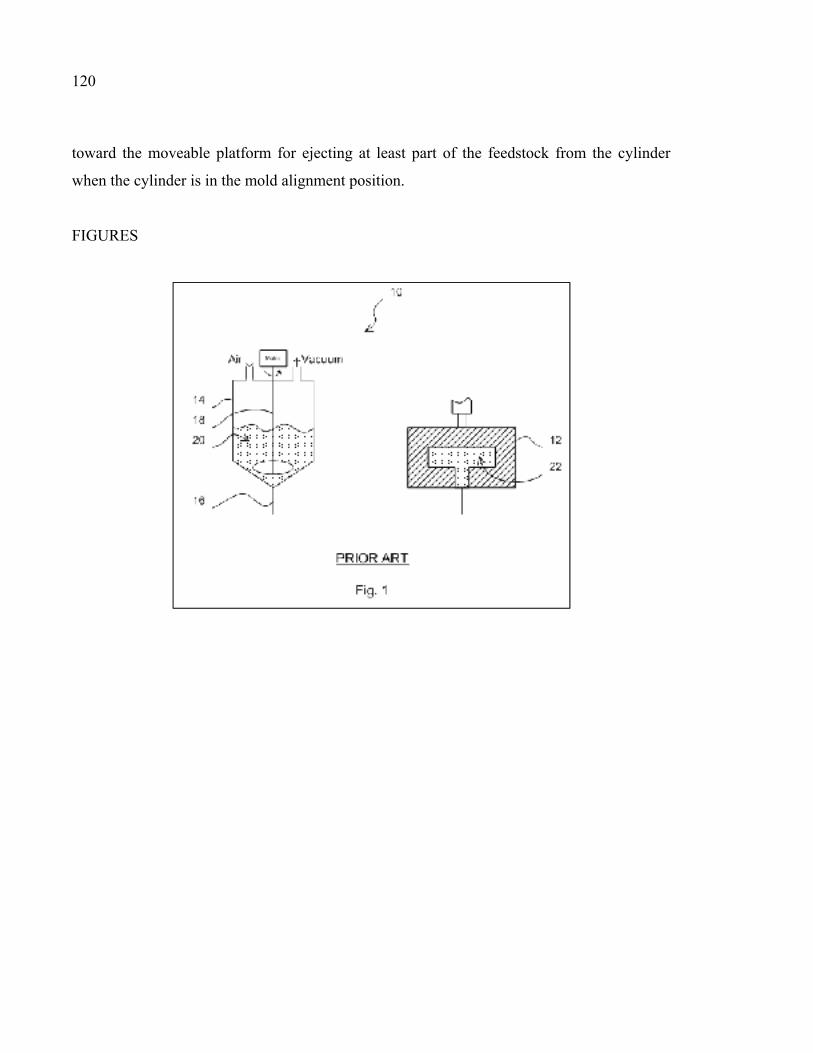
120
toward the moveable platform for ejecting at least part of the feedstock from the cylinder
when the cylinder is in the mold alignment position.
FIGURES
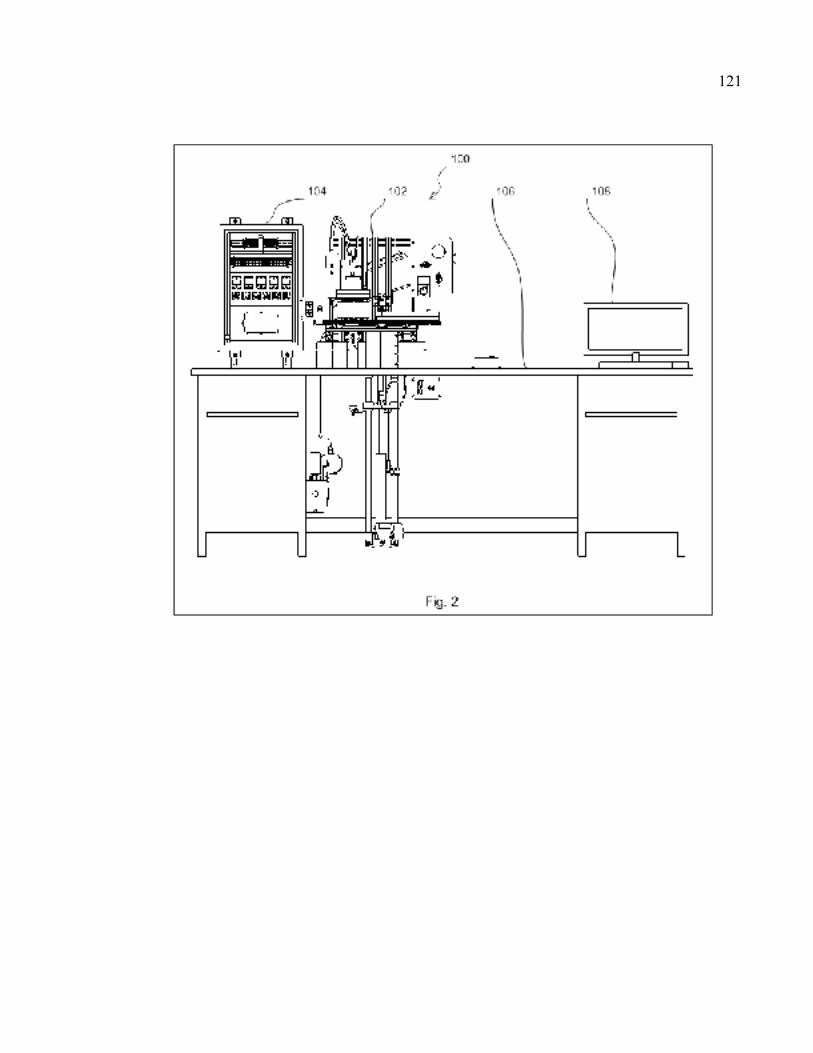
121
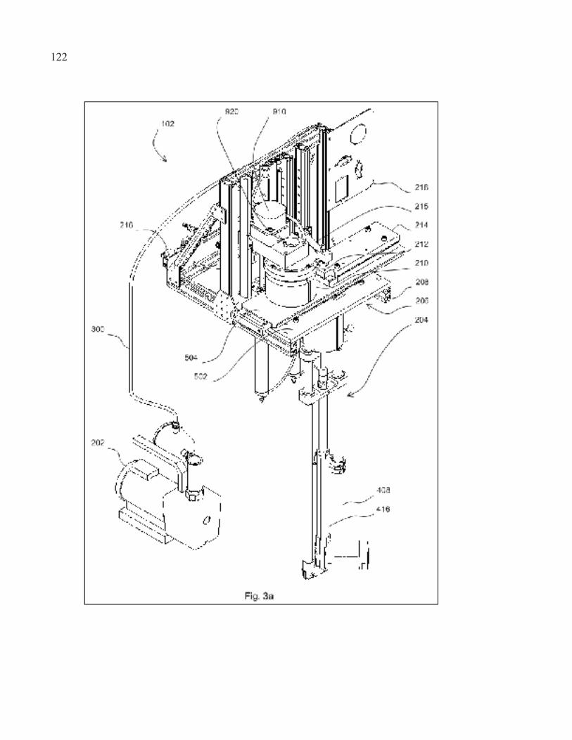
122
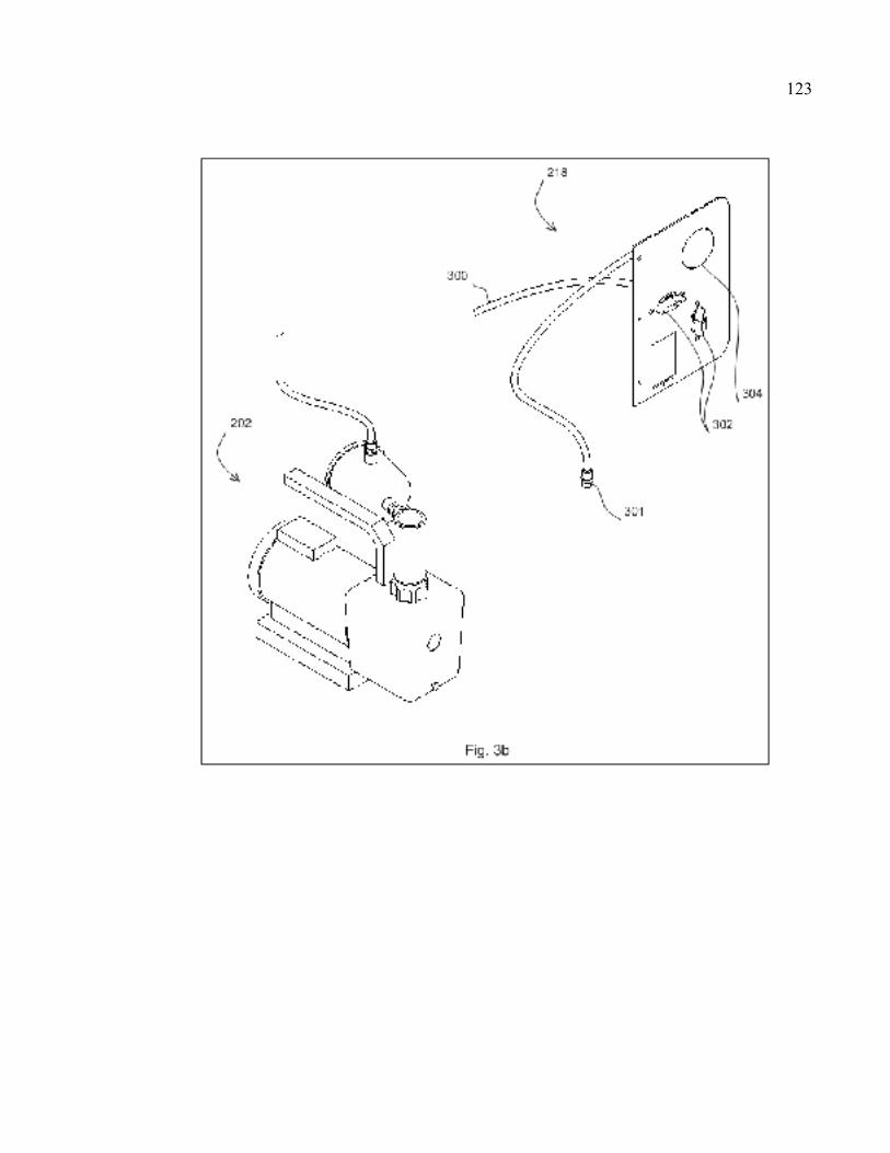
123
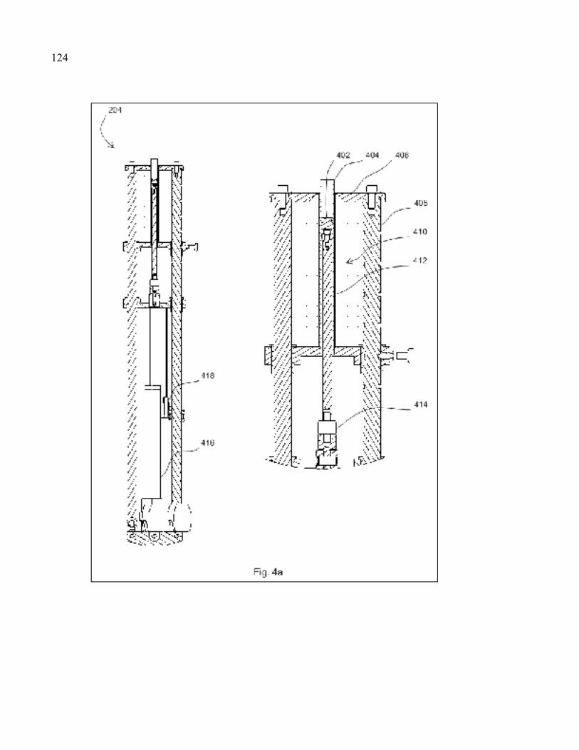
124
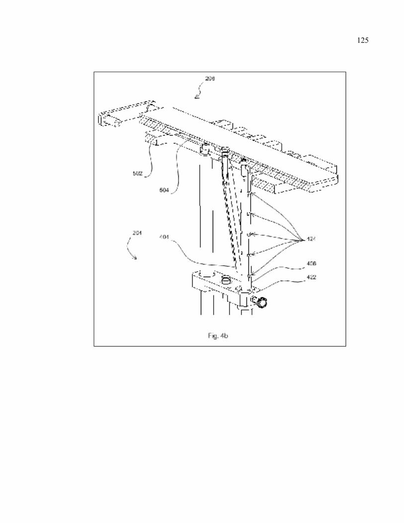
125
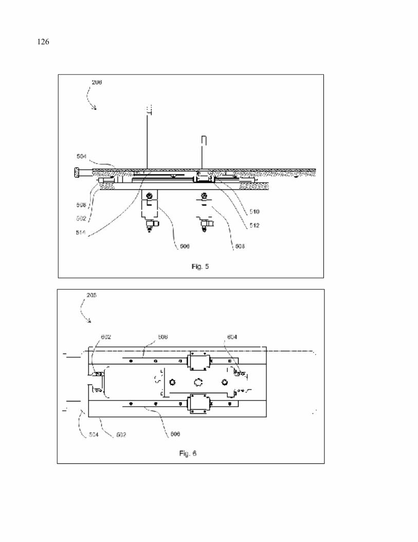
126
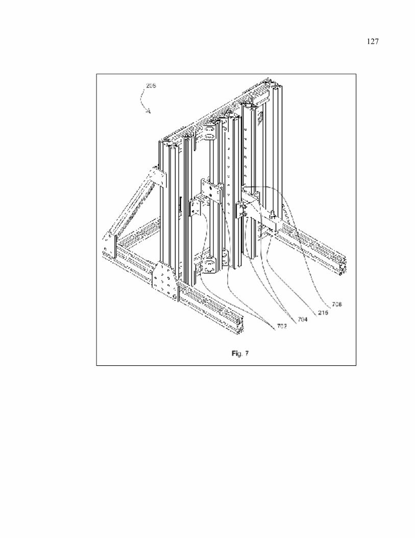
127
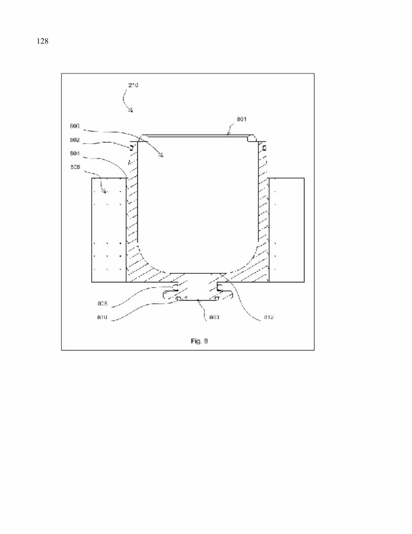
128
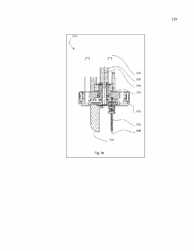
129
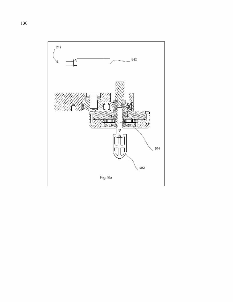
130
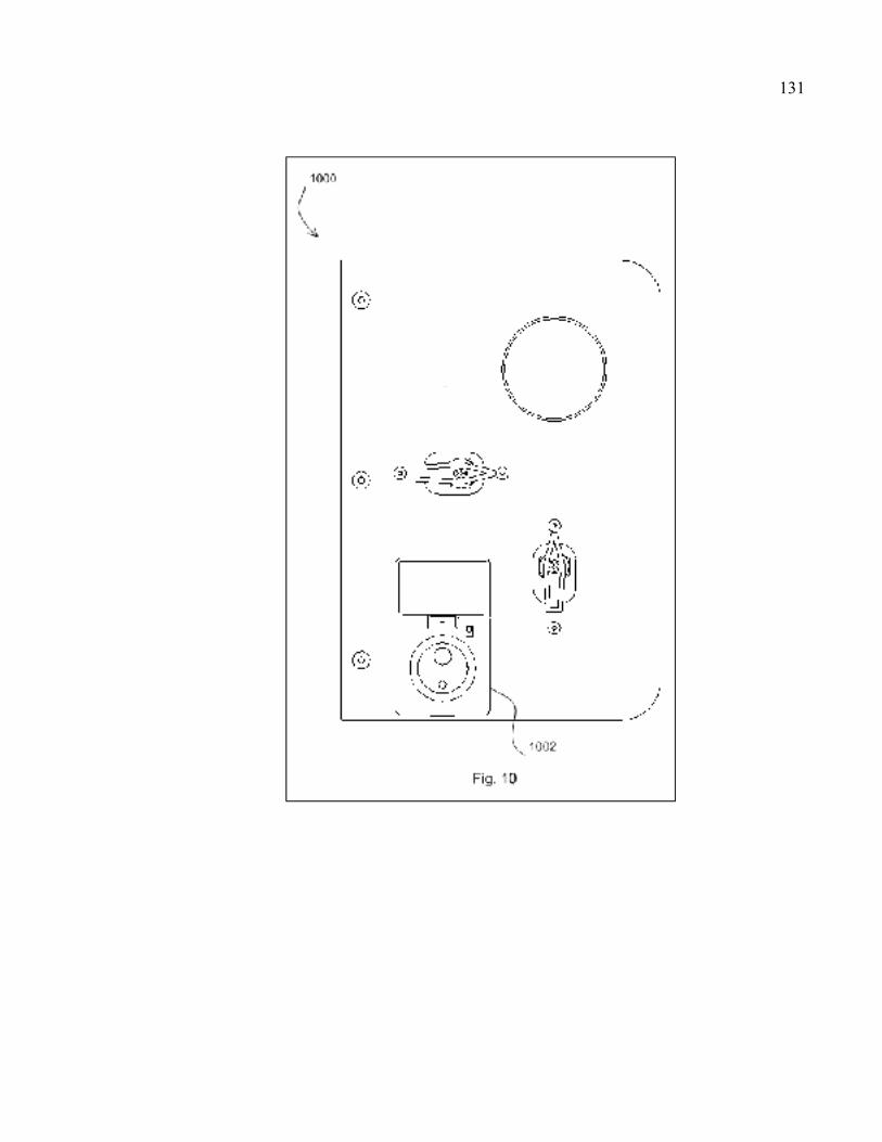
131
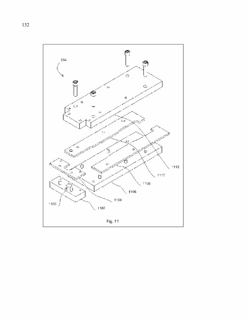
132
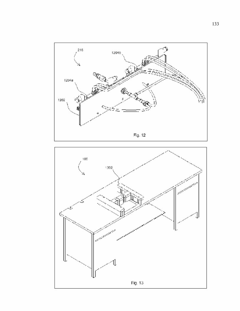
133
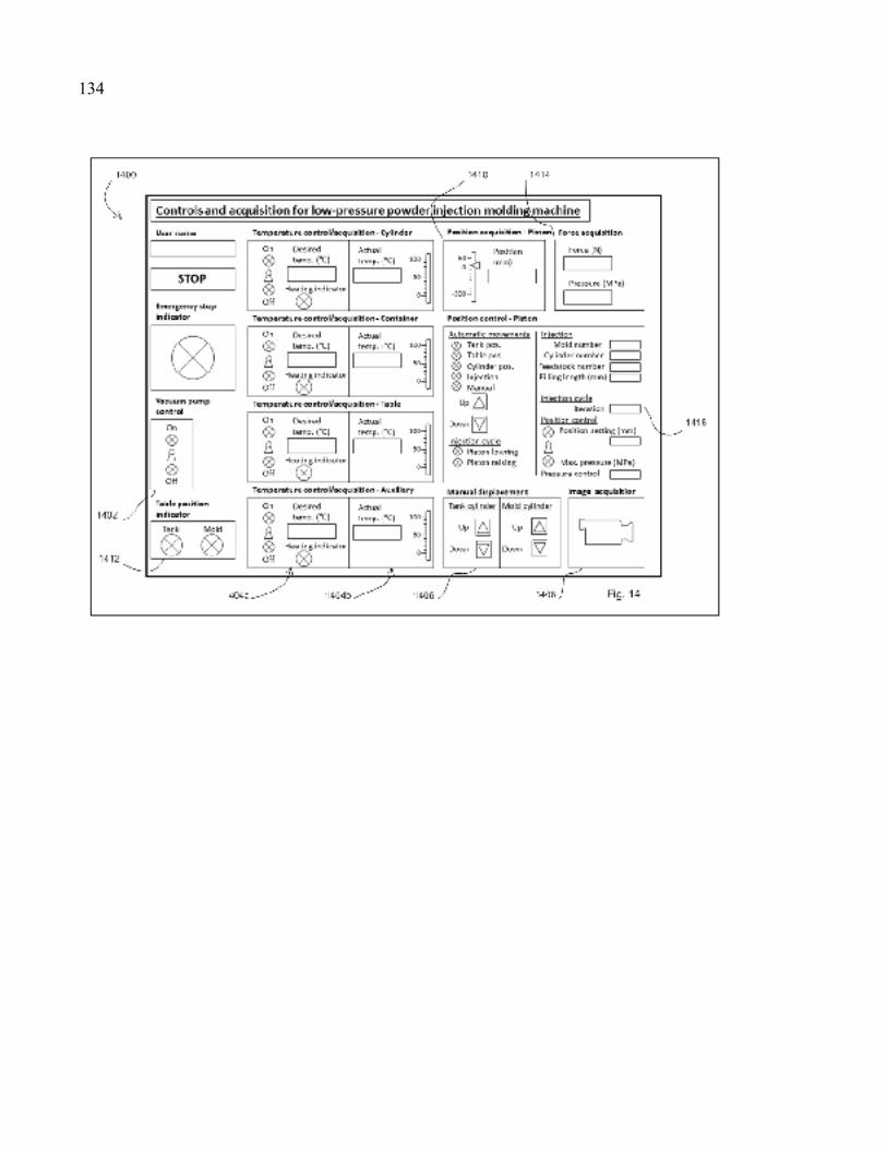
134
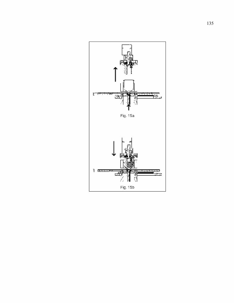
135
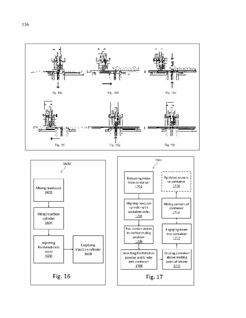
136
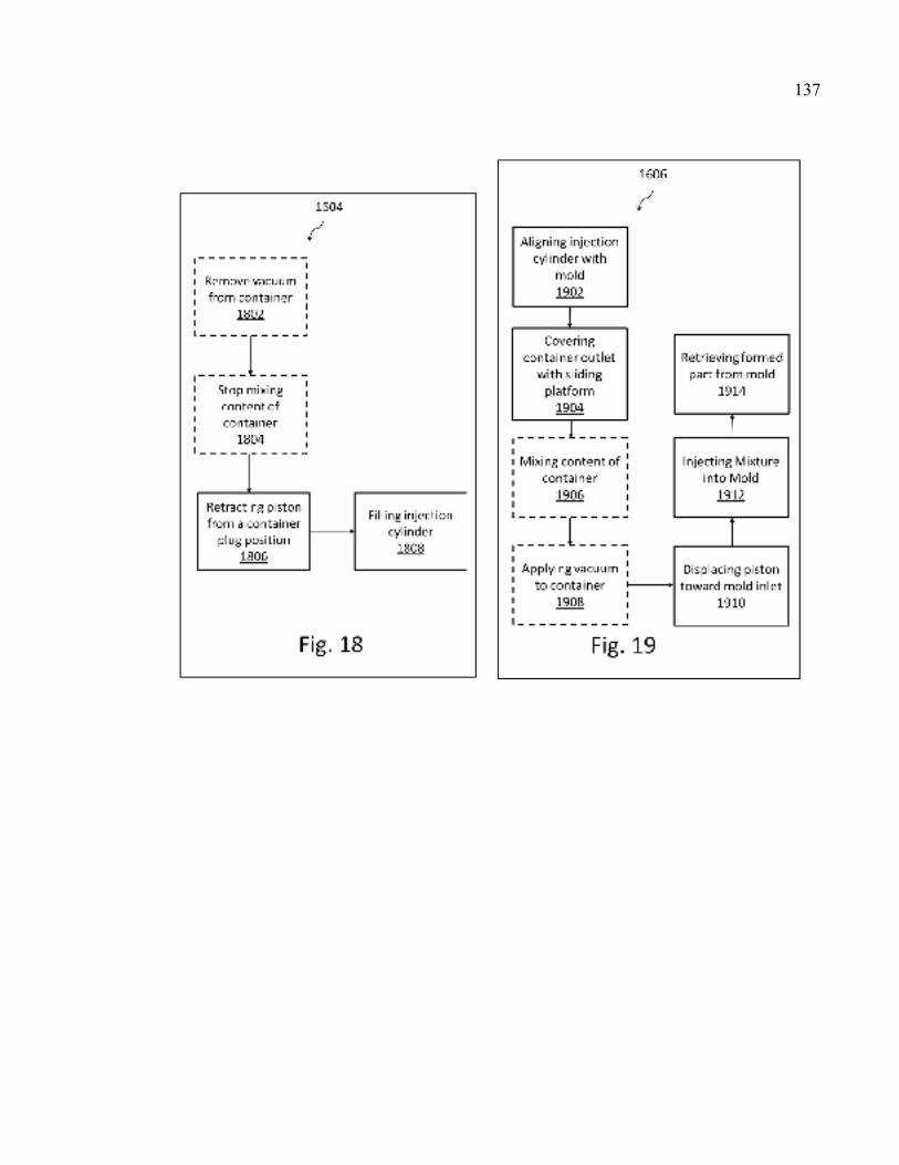
137
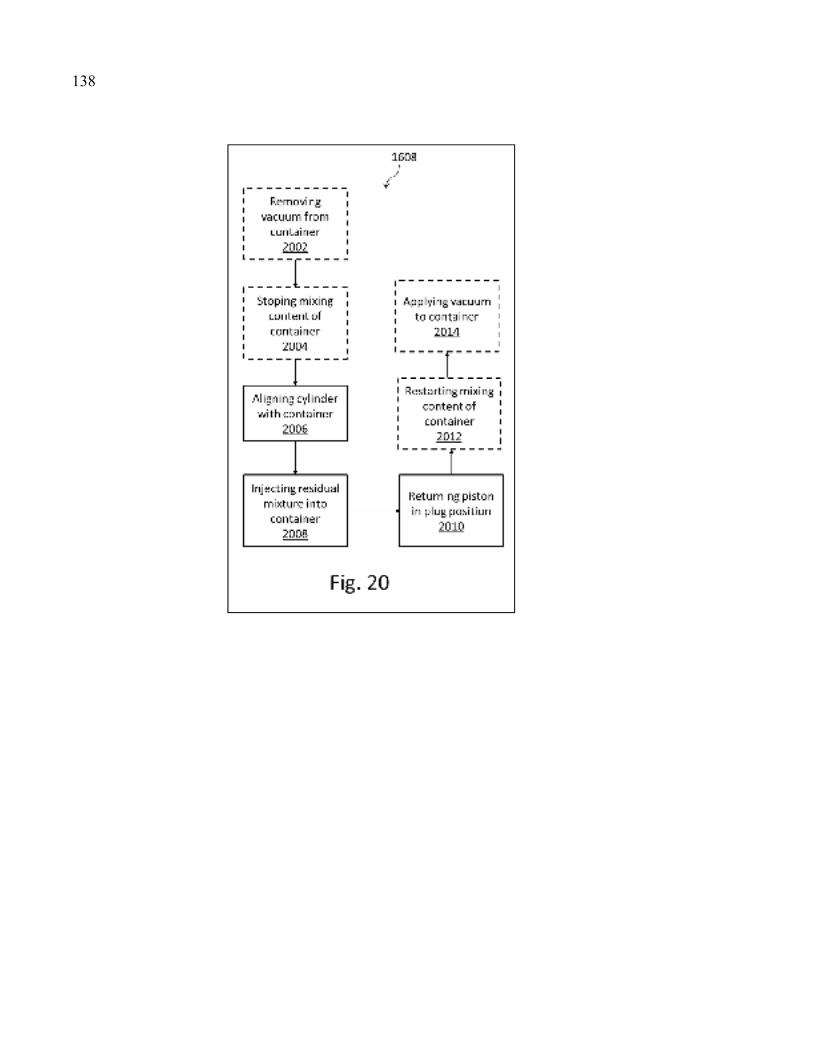
138

ANNEXE III
DESSINS D’ASSEMBLAGE ET LISTE DE PIÈCES
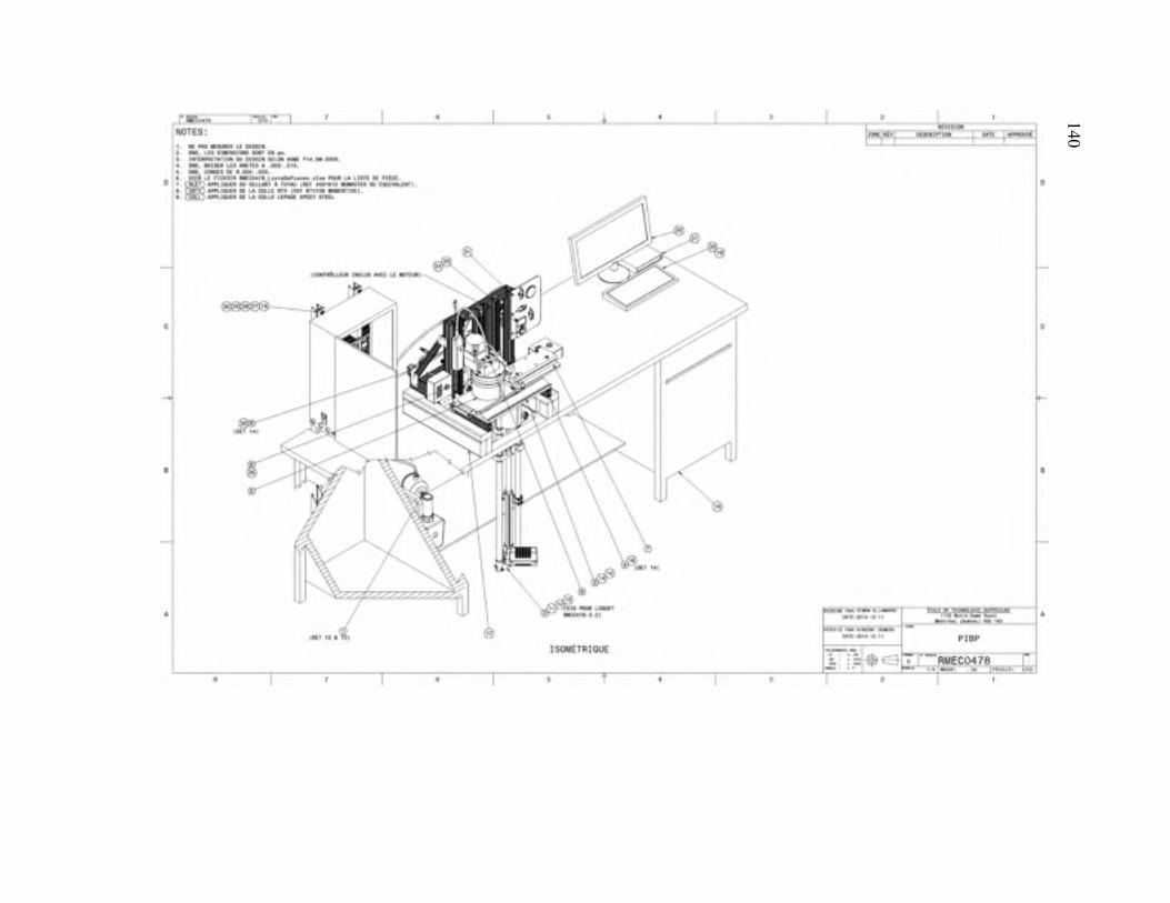
140 140
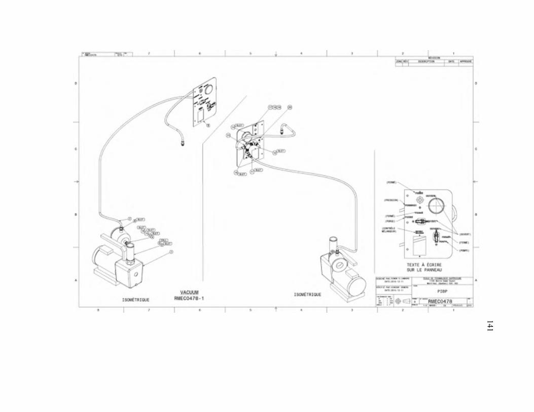
141
141
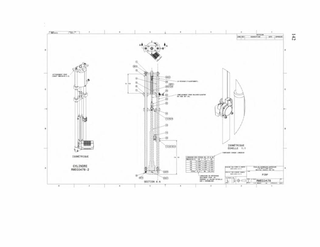
142 142
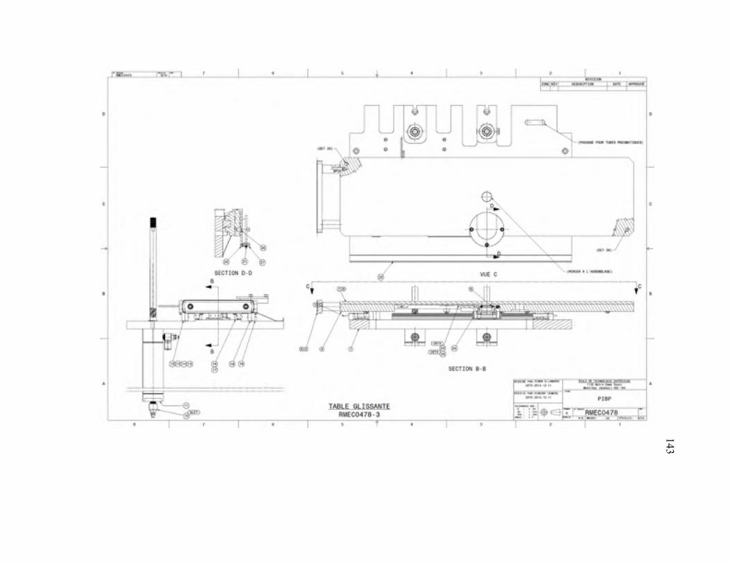
143 143
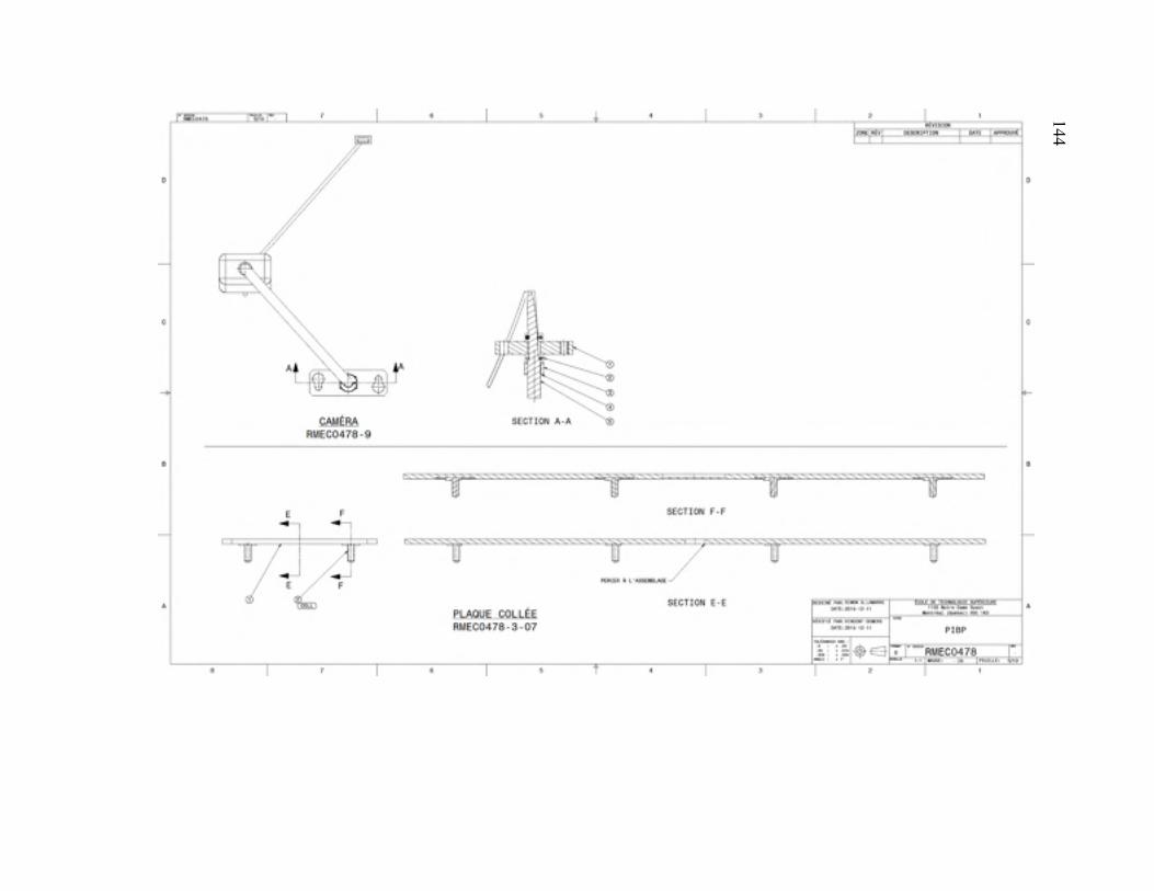
144 144
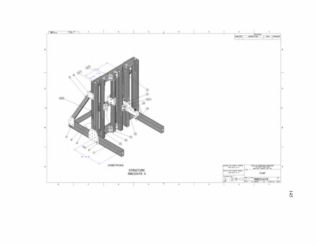
145 145
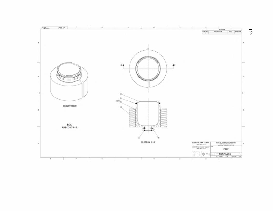
146 146
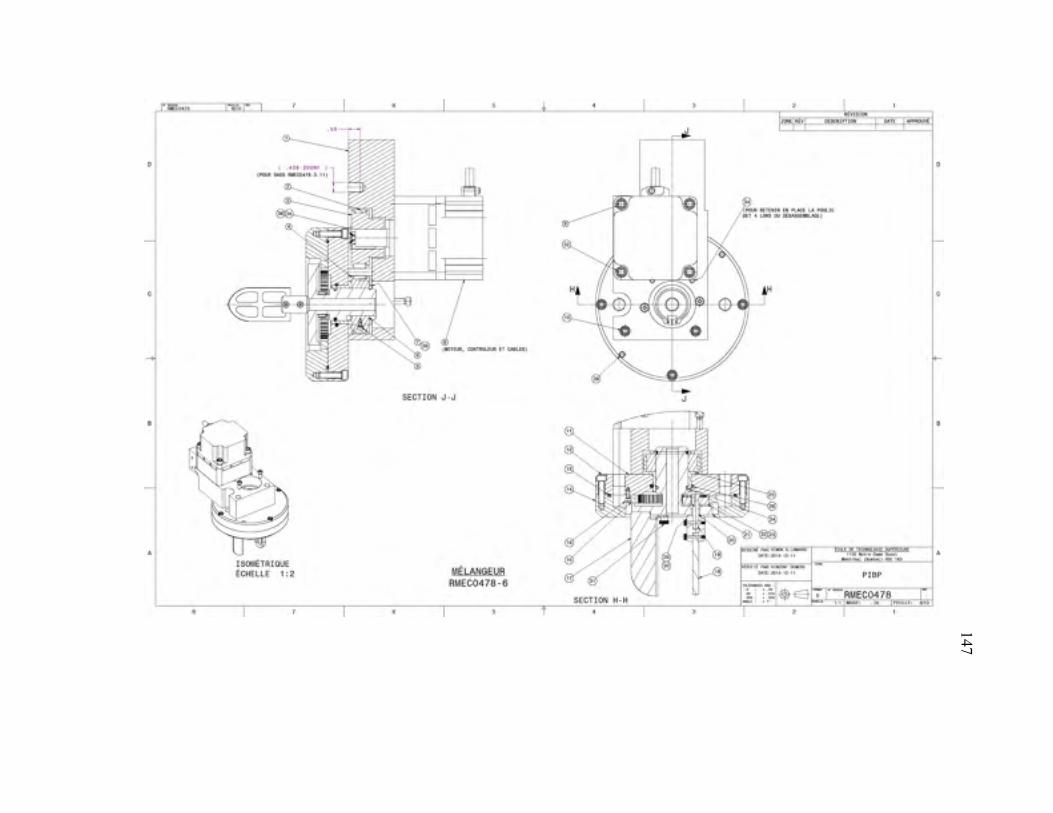
147 147
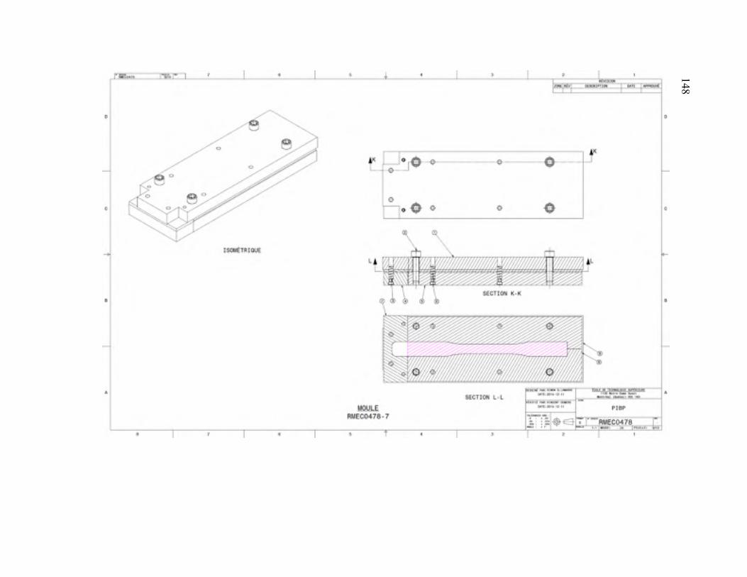
148 148
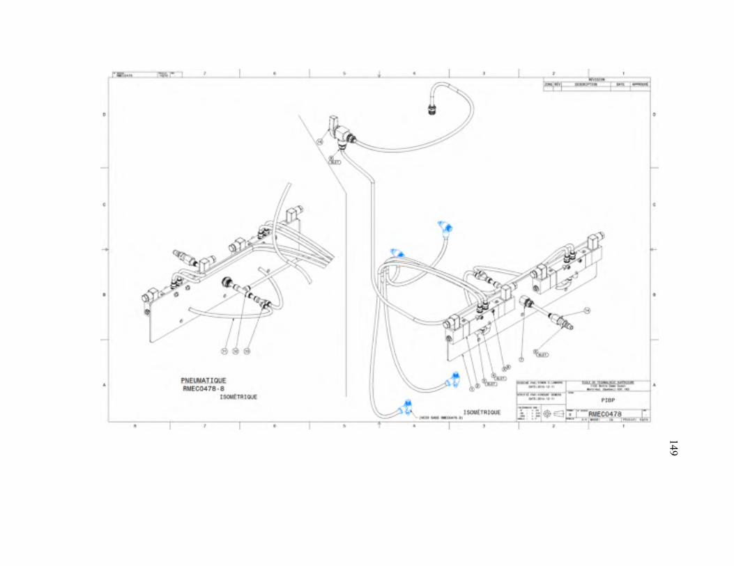
149 149
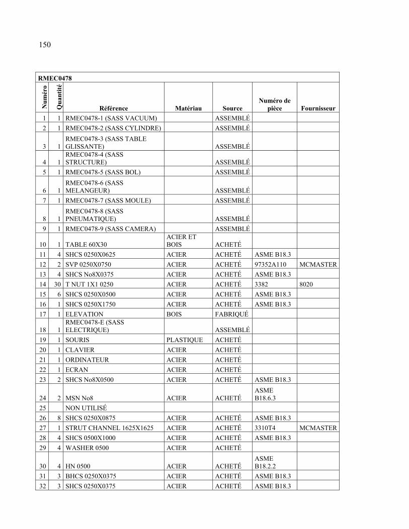
RMEC0478
Nu
mér
o
Qu
anti
té
Référence Matériau Source Numéro de
pièce Fournisseur
1 1 RMEC0478-1 (SASS VACUUM) ASSEMBLÉ
2 1 RMEC0478-2 (SASS CYLINDRE) ASSEMBLÉ
3 1 RMEC0478-3 (SASS TABLE GLISSANTE) ASSEMBLÉ
4 1 RMEC0478-4 (SASS STRUCTURE) ASSEMBLÉ
5 1 RMEC0478-5 (SASS BOL) ASSEMBLÉ
6 1 RMEC0478-6 (SASS MELANGEUR) ASSEMBLÉ
7 1 RMEC0478-7 (SASS MOULE) ASSEMBLÉ
8 1 RMEC0478-8 (SASS PNEUMATIQUE) ASSEMBLÉ
9 1 RMEC0478-9 (SASS CAMERA) ASSEMBLÉ
10 1 TABLE 60X30 ACIER ET BOIS ACHETÉ
11 4 SHCS 0250X0625 ACIER ACHETÉ ASME B18.3
12 2 SVP 0250X0750 ACIER ACHETÉ 97352A110 MCMASTER
13 4 SHCS No8X0375 ACIER ACHETÉ ASME B18.3
14 30 T NUT 1X1 0250 ACIER ACHETÉ 3382 8020
15 6 SHCS 0250X0500 ACIER ACHETÉ ASME B18.3
16 1 SHCS 0250X1750 ACIER ACHETÉ ASME B18.3
17 1 ELEVATION BOIS FABRIQUÉ
18 1 RMEC0478-E (SASS ELECTRIQUE) ASSEMBLÉ
19 1 SOURIS PLASTIQUE ACHETÉ
20 1 CLAVIER ACIER ACHETÉ
21 1 ORDINATEUR ACIER ACHETÉ
22 1 ECRAN ACIER ACHETÉ
23 2 SHCS No8X0500 ACIER ACHETÉ ASME B18.3
24 2 MSN No8 ACIER ACHETÉ ASME B18.6.3
25 NON UTILISÉ
26 8 SHCS 0250X0875 ACIER ACHETÉ ASME B18.3
27 1 STRUT CHANNEL 1625X1625 ACIER ACHETÉ 3310T4 MCMASTER
28 4 SHCS 0500X1000 ACIER ACHETÉ ASME B18.3
29 4 WASHER 0500 ACIER ACHETÉ
30 4 HN 0500 ACIER ACHETÉ ASME B18.2.2
31 3 BHCS 0250X0375 ACIER ACHETÉ ASME B18.3
32 3 SHCS 0250X0375 ACIER ACHETÉ ASME B18.3
150
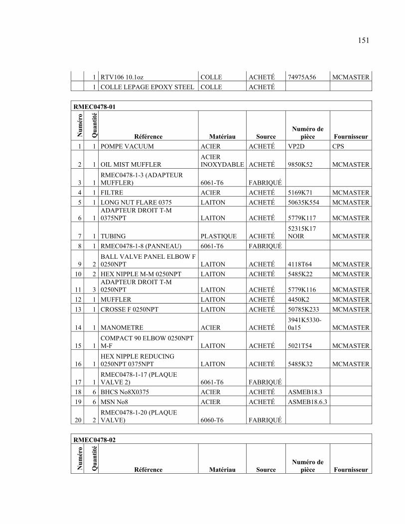
151
1 RTV106 10.1oz COLLE ACHETÉ 74975A56 MCMASTER
1 COLLE LEPAGE EPOXY STEEL COLLE ACHETÉ
RMEC0478-01
Nu
mér
o
Qu
anti
té
Référence Matériau Source Numéro de
pièce Fournisseur
1 1 POMPE VACUUM ACIER ACHETÉ VP2D CPS
2 1 OIL MIST MUFFLER ACIER INOXYDABLE ACHETÉ 9850K52 MCMASTER
3 1 RMEC0478-1-3 (ADAPTEUR MUFFLER) 6061-T6 FABRIQUÉ
4 1 FILTRE ACIER ACHETÉ 5169K71 MCMASTER
5 1 LONG NUT FLARE 0375 LAITON ACHETÉ 50635K554 MCMASTER
6 1 ADAPTEUR DROIT T-M 0375NPT LAITON ACHETÉ 5779K117 MCMASTER
7 1 TUBING PLASTIQUE ACHETÉ 52315K17 NOIR MCMASTER
8 1 RMEC0478-1-8 (PANNEAU) 6061-T6 FABRIQUÉ
9 2 BALL VALVE PANEL ELBOW F 0250NPT LAITON ACHETÉ 4118T64 MCMASTER
10 2 HEX NIPPLE M-M 0250NPT LAITON ACHETÉ 5485K22 MCMASTER
11 3 ADAPTEUR DROIT T-M 0250NPT LAITON ACHETÉ 5779K116 MCMASTER
12 1 MUFFLER LAITON ACHETÉ 4450K2 MCMASTER
13 1 CROSSE F 0250NPT LAITON ACHETÉ 50785K233 MCMASTER
14 1 MANOMETRE ACIER ACHETÉ 3941K5330-0a15 MCMASTER
15 1 COMPACT 90 ELBOW 0250NPT M-F LAITON ACHETÉ 5021T54 MCMASTER
16 1 HEX NIPPLE REDUCING 0250NPT 0375NPT LAITON ACHETÉ 5485K32 MCMASTER
17 1 RMEC0478-1-17 (PLAQUE VALVE 2) 6061-T6 FABRIQUÉ
18 6 BHCS No8X0375 ACIER ACHETÉ ASMEB18.3
19 6 MSN No8 ACIER ACHETÉ ASMEB18.6.3
20 2 RMEC0478-1-20 (PLAQUE VALVE) 6060-T6 FABRIQUÉ
RMEC0478-02
Nu
mér
o
Qu
anti
té
Référence Matériau Source Numéro de
pièce Fournisseur
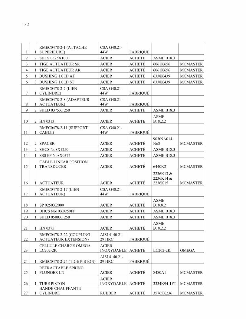
152
1 1 RMEC0478-2-1 (ATTACHE SUPERIEURE)
CSA G40.21-44W FABRIQUÉ
2 2 SHCS 0375X1000 ACIER ACHETÉ ASME B18.3
3 1 TIGE ACTUATEUR SR ACIER ACHETÉ 6061K656 MCMASTER
4 1 TIGE ACTUATEUR AR ACIER ACHETÉ 6061K656 MCMASTER
5 1 BUSHING 1.0 ID AT ACIER ACHETÉ 6338K439 MCMASTER
6 3 BUSHING 1.0 ID ST ACIER ACHETÉ 6338K439 MCMASTER
7 1 RMEC0478-2-7 (LIEN CYLINDRE)
CSA G40.21-44W FABRIQUÉ
8 1 RMEC0478-2-8 (ADAPTEUR ACTUATEUR)
CSA G40.21-44W FABRIQUÉ
9 2 SHLD 0375X1250 ACIER ACHETÉ ASME B18.3
10 2 HN 0313 ACIER ACHETÉ ASME B18.2.2
11 1 RMEC0478-2-11 (SUPPORT CABLE)
CSA G40.21-44W FABRIQUÉ
12 2 SPACER ACIER ACHETÉ 90309A014-No8 MCMASTER
13 2 SHCS No8X1250 ACIER ACHETÉ ASME B18.3
14 1 SSS FP No8X0375 ACIER ACHETÉ ASME B18.3
15 1 CABLE LINEAR POSITION TRANSDUCER ACIER ACHETÉ 6440K2 MCMASTER
16 1 ACTUATEUR ACIER ACHETÉ
2236K13 & 2236K14 & 2236K15 MCMASTER
17 1 RMEC0478-2-17 (LIEN ACTUATEUR)
CSA G40.21-44W FABRIQUÉ
18 1 SP 0250X2000 ACIER ACHETÉ ASME B18.8.2
19 1 BHCS No10X0250FP ACIER ACHETÉ ASME B18.3
20 1 SHLD 0500X1250 ACIER ACHETÉ ASME B18.3
21 1 HN 0375 ACIER ACHETÉ ASME B18.2.2
22 1 RMEC0478-2-22 (COUPLING ACTUATEUR EXTENSION)
AISI 4140 21-29 HRC FABRIQUÉ
23 1 CELLULE CHARGE OMEGA LC202-2K
ACIER INOXYDABLE ACHETÉ LC202-2K OMEGA
24 1 RMEC0478-2-24 (TIGE PISTON) AISI 4140 21-29 HRC FABRIQUÉ
25 1 RETRACTABLE SPRING PLUNGER LN ACIER ACHETÉ 8480A1 MCMASTER
26 1 TUBE PISTON ACIER INOXYDABLE ACHETÉ 3334K94-1FT MCMASTER
27 1 BANDE CHAUFFANTE CYLINDRE RUBBER ACHETÉ 35765K236 MCMASTER
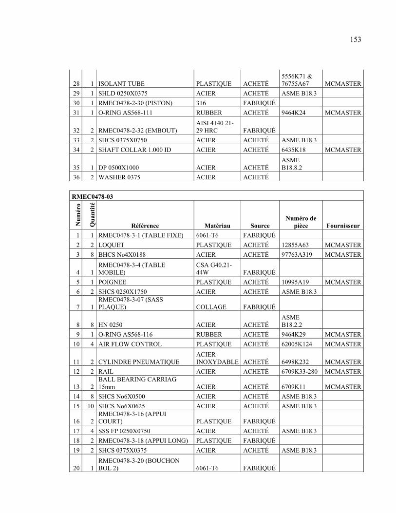
153
28 1 ISOLANT TUBE PLASTIQUE ACHETÉ 5556K71 & 76755A67 MCMASTER
29 1 SHLD 0250X0375 ACIER ACHETÉ ASME B18.3
30 1 RMEC0478-2-30 (PISTON) 316 FABRIQUÉ
31 1 O-RING AS568-111 RUBBER ACHETÉ 9464K24 MCMASTER
32 2 RMEC0478-2-32 (EMBOUT) AISI 4140 21-29 HRC FABRIQUÉ
33 2 SHCS 0375X0750 ACIER ACHETÉ ASME B18.3
34 2 SHAFT COLLAR 1.000 ID ACIER ACHETÉ 6435K18 MCMASTER
35 1 DP 0500X1000 ACIER ACHETÉ ASME B18.8.2
36 2 WASHER 0375 ACIER ACHETÉ
RMEC0478-03
Nu
mér
o
Qu
anti
té
Référence Matériau Source Numéro de
pièce Fournisseur
1 1 RMEC0478-3-1 (TABLE FIXE) 6061-T6 FABRIQUÉ
2 2 LOQUET PLASTIQUE ACHETÉ 12855A63 MCMASTER
3 8 BHCS No4X0188 ACIER ACHETÉ 97763A319 MCMASTER
4 1 RMEC0478-3-4 (TABLE MOBILE)
CSA G40.21-44W FABRIQUÉ
5 1 POIGNEE PLASTIQUE ACHETÉ 10995A19 MCMASTER
6 2 SHCS 0250X1750 ACIER ACHETÉ ASME B18.3
7 1 RMEC0478-3-07 (SASS PLAQUE) COLLAGE FABRIQUÉ
8 8 HN 0250 ACIER ACHETÉ ASME B18.2.2
9 1 O-RING AS568-116 RUBBER ACHETÉ 9464K29 MCMASTER
10 4 AIR FLOW CONTROL PLASTIQUE ACHETÉ 62005K124 MCMASTER
11 2 CYLINDRE PNEUMATIQUE ACIER INOXYDABLE ACHETÉ 6498K232 MCMASTER
12 2 RAIL ACIER ACHETÉ 6709K33-280 MCMASTER
13 2 BALL BEARING CARRIAG 15mm ACIER ACHETÉ 6709K11 MCMASTER
14 8 SHCS No6X0500 ACIER ACHETÉ ASME B18.3
15 10 SHCS No6X0625 ACIER ACHETÉ ASME B18.3
16 2 RMEC0478-3-16 (APPUI COURT) PLASTIQUE FABRIQUÉ
17 4 SSS FP 0250X0750 ACIER ACHETÉ ASME B18.3
18 2 RMEC0478-3-18 (APPUI LONG) PLASTIQUE FABRIQUÉ
19 2 SHCS 0375X0375 ACIER ACHETÉ ASME B18.3
20 1 RMEC0478-3-20 (BOUCHON BOL 2) 6061-T6 FABRIQUÉ
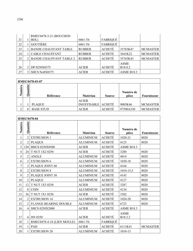
154
21 1 RMEC0478-3-21 (BOUCHON BOL) 6061-T6 FABRIQUÉ
22 1 GOUTIÈRE 6061-T6 FABRIQUÉ
23 1 BANDE CHAUFFANT TABLE RUBBER ACHETÉ 35765K47 MCMASTER
24 1 CABLE CHAUFFANT RUBBER ACHETÉ 3641K22 MCMASTER
25 2 BANDE CHAUFFANT TABLE 2 RUBBER ACHETÉ 35765K43 MCMASTER
26 3 DP 0250X0375 ACIER ACHETÉ ASME B18.8.2
27 3 SHCS No8X0375 ACIER ACHETÉ ASME B18.3
RMEC0478-03-07
Nu
mér
o
Qu
anti
té
Référence Matériau Source Numéro de
pièce Fournisseur
1 1 PLAQUE ACIER INOXYDABLE ACHETÉ 9085K46 MCMASTER
2 8 BASE STUD ACIER ACHETÉ 97590A330 MCMASTER
RMEC0478-04
Nu
mér
o
Qu
anti
té
Référence Matériau Source Numéro de
pièce Fournisseur
1 2 EXTRUSION 1 ALUMINIUM ACHETÉ 1020-21 8020
2 2 PLAQUE ALUMINIUM ACHETÉ 4125 8020
3 120 BHCS 0250X0500 ACIER ACHETÉ ASME B18.3
4 24 T NUT 1X2 0250 ACIER ACHETÉ 3280 8020
5 2 ANGLE ALUMINIUM ACHETÉ 4014 8020
6 2 EXTRUSION 6 ALUMINIUM ACHETÉ 1020-18 8020
7 2 PLAQUE JOINT 60 ALUMINIUM ACHETÉ 4164 8020
8 2 EXTRUSION 8 ALUMINIUM ACHETÉ 1010-15,5 8020
9 2 PLAQUE JOINT 30 ALUMINIUM ACHETÉ 4143 8020
10 2 PLAQUE ALUMINIUM ACHETÉ 4127 8020
11 12 T NUT 1X3 0250 ACIER ACHETÉ 3287 8020
12 8 COIN ALUMINIUM ACHETÉ 4134 8020
13 36 T NUT 1X1 0250 ACIER ACHETÉ 3382 8020
14 2 EXTRUSION 14 ALUMINIUM ACHETÉ 1020-20 8020
15 2 FLANGE BEARING DOUBLE ALUMINIUM ACHETÉ 6723 8020
16 4 SHCS 0250X2000 ACIER ACHETÉ ASME B18.3
17 4 HN 0250 ACIER ACHETÉ ASME B18.2.2
18 1 RMEC0478-4-18 (LIEN MOULE) 6061-T6 FABRIQUÉ
19 1 PAD ACIER ACHETÉ 6111K41 MCMASTER
20 1 EXTRUSION 20 ALUMINIUM ACHETÉ 1010-15
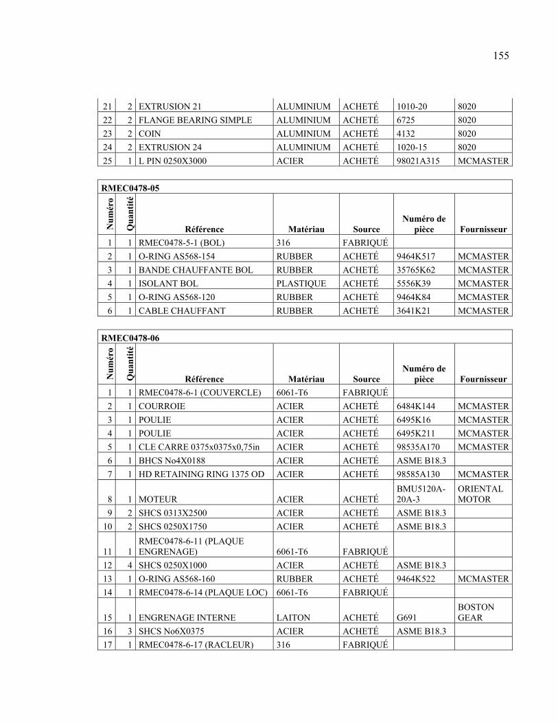
155
21 2 EXTRUSION 21 ALUMINIUM ACHETÉ 1010-20 8020
22 2 FLANGE BEARING SIMPLE ALUMINIUM ACHETÉ 6725 8020
23 2 COIN ALUMINIUM ACHETÉ 4132 8020
24 2 EXTRUSION 24 ALUMINIUM ACHETÉ 1020-15 8020
25 1 L PIN 0250X3000 ACIER ACHETÉ 98021A315 MCMASTER
RMEC0478-05
Nu
mér
o
Qu
anti
té
Référence Matériau Source Numéro de
pièce Fournisseur
1 1 RMEC0478-5-1 (BOL) 316 FABRIQUÉ
2 1 O-RING AS568-154 RUBBER ACHETÉ 9464K517 MCMASTER
3 1 BANDE CHAUFFANTE BOL RUBBER ACHETÉ 35765K62 MCMASTER
4 1 ISOLANT BOL PLASTIQUE ACHETÉ 5556K39 MCMASTER
5 1 O-RING AS568-120 RUBBER ACHETÉ 9464K84 MCMASTER
6 1 CABLE CHAUFFANT RUBBER ACHETÉ 3641K21 MCMASTER
RMEC0478-06
Nu
mér
o
Qu
anti
té
Référence Matériau Source Numéro de
pièce Fournisseur
1 1 RMEC0478-6-1 (COUVERCLE) 6061-T6 FABRIQUÉ
2 1 COURROIE ACIER ACHETÉ 6484K144 MCMASTER
3 1 POULIE ACIER ACHETÉ 6495K16 MCMASTER
4 1 POULIE ACIER ACHETÉ 6495K211 MCMASTER
5 1 CLE CARRE 0375x0375x0,75in ACIER ACHETÉ 98535A170 MCMASTER
6 1 BHCS No4X0188 ACIER ACHETÉ ASME B18.3
7 1 HD RETAINING RING 1375 OD ACIER ACHETÉ 98585A130 MCMASTER
8 1 MOTEUR ACIER ACHETÉ BMU5120A-20A-3
ORIENTAL MOTOR
9 2 SHCS 0313X2500 ACIER ACHETÉ ASME B18.3
10 2 SHCS 0250X1750 ACIER ACHETÉ ASME B18.3
11 1 RMEC0478-6-11 (PLAQUE ENGRENAGE) 6061-T6 FABRIQUÉ
12 4 SHCS 0250X1000 ACIER ACHETÉ ASME B18.3
13 1 O-RING AS568-160 RUBBER ACHETÉ 9464K522 MCMASTER
14 1 RMEC0478-6-14 (PLAQUE LOC) 6061-T6 FABRIQUÉ
15 1 ENGRENAGE INTERNE LAITON ACHETÉ G691 BOSTON GEAR
16 3 SHCS No6X0375 ACIER ACHETÉ ASME B18.3
17 1 RMEC0478-6-17 (RACLEUR) 316 FABRIQUÉ
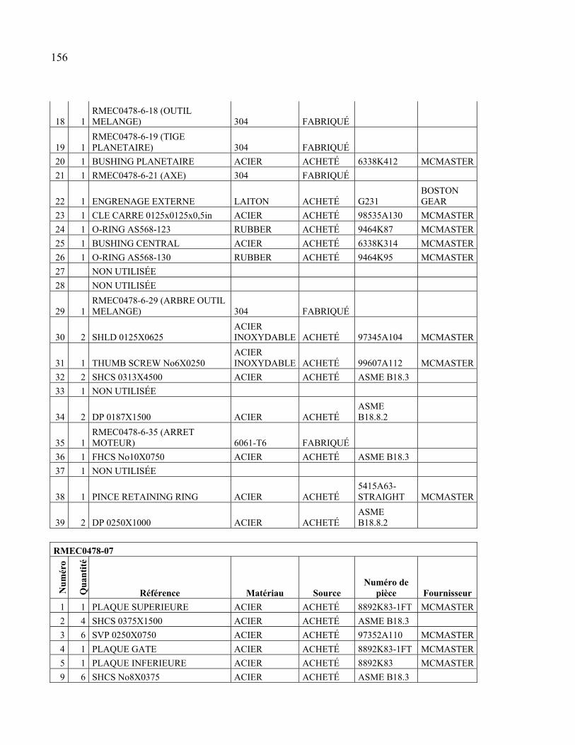
156
18 1 RMEC0478-6-18 (OUTIL MELANGE) 304 FABRIQUÉ
19 1 RMEC0478-6-19 (TIGE PLANETAIRE) 304 FABRIQUÉ
20 1 BUSHING PLANETAIRE ACIER ACHETÉ 6338K412 MCMASTER
21 1 RMEC0478-6-21 (AXE) 304 FABRIQUÉ
22 1 ENGRENAGE EXTERNE LAITON ACHETÉ G231 BOSTON GEAR
23 1 CLE CARRE 0125x0125x0,5in ACIER ACHETÉ 98535A130 MCMASTER
24 1 O-RING AS568-123 RUBBER ACHETÉ 9464K87 MCMASTER
25 1 BUSHING CENTRAL ACIER ACHETÉ 6338K314 MCMASTER
26 1 O-RING AS568-130 RUBBER ACHETÉ 9464K95 MCMASTER
27 NON UTILISÉE
28 NON UTILISÉE
29 1 RMEC0478-6-29 (ARBRE OUTIL MELANGE) 304 FABRIQUÉ
30 2 SHLD 0125X0625 ACIER INOXYDABLE ACHETÉ 97345A104 MCMASTER
31 1 THUMB SCREW No6X0250 ACIER INOXYDABLE ACHETÉ 99607A112 MCMASTER
32 2 SHCS 0313X4500 ACIER ACHETÉ ASME B18.3
33 1 NON UTILISÉE
34 2 DP 0187X1500 ACIER ACHETÉ ASME B18.8.2
35 1 RMEC0478-6-35 (ARRET MOTEUR) 6061-T6 FABRIQUÉ
36 1 FHCS No10X0750 ACIER ACHETÉ ASME B18.3
37 1 NON UTILISÉE
38 1 PINCE RETAINING RING ACIER ACHETÉ 5415A63-STRAIGHT MCMASTER
39 2 DP 0250X1000 ACIER ACHETÉ ASME B18.8.2
RMEC0478-07
Nu
mér
o
Qu
anti
té
Référence Matériau Source Numéro de
pièce Fournisseur
1 1 PLAQUE SUPERIEURE ACIER ACHETÉ 8892K83-1FT MCMASTER
2 4 SHCS 0375X1500 ACIER ACHETÉ ASME B18.3
3 6 SVP 0250X0750 ACIER ACHETÉ 97352A110 MCMASTER
4 1 PLAQUE GATE ACIER ACHETÉ 8892K83-1FT MCMASTER
5 1 PLAQUE INFERIEURE ACIER ACHETÉ 8892K83 MCMASTER
9 6 SHCS No8X0375 ACIER ACHETÉ ASME B18.3
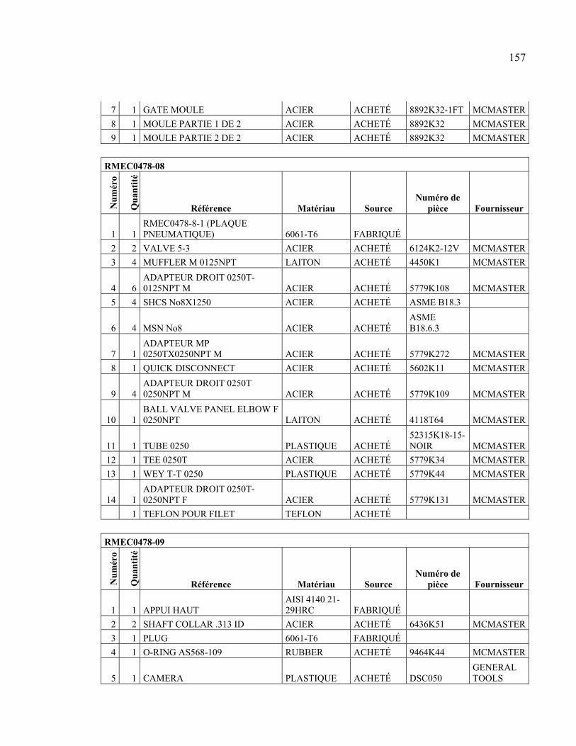
157
7 1 GATE MOULE ACIER ACHETÉ 8892K32-1FT MCMASTER
8 1 MOULE PARTIE 1 DE 2 ACIER ACHETÉ 8892K32 MCMASTER
9 1 MOULE PARTIE 2 DE 2 ACIER ACHETÉ 8892K32 MCMASTER
RMEC0478-08
Nu
mér
o
Qu
anti
té
Référence Matériau Source Numéro de
pièce Fournisseur
1 1 RMEC0478-8-1 (PLAQUE PNEUMATIQUE) 6061-T6 FABRIQUÉ
2 2 VALVE 5-3 ACIER ACHETÉ 6124K2-12V MCMASTER
3 4 MUFFLER M 0125NPT LAITON ACHETÉ 4450K1 MCMASTER
4 6 ADAPTEUR DROIT 0250T-0125NPT M ACIER ACHETÉ 5779K108 MCMASTER
5 4 SHCS No8X1250 ACIER ACHETÉ ASME B18.3
6 4 MSN No8 ACIER ACHETÉ ASME B18.6.3
7 1 ADAPTEUR MP 0250TX0250NPT M ACIER ACHETÉ 5779K272 MCMASTER
8 1 QUICK DISCONNECT ACIER ACHETÉ 5602K11 MCMASTER
9 4 ADAPTEUR DROIT 0250T 0250NPT M ACIER ACHETÉ 5779K109 MCMASTER
10 1 BALL VALVE PANEL ELBOW F 0250NPT LAITON ACHETÉ 4118T64 MCMASTER
11 1 TUBE 0250 PLASTIQUE ACHETÉ 52315K18-15-NOIR MCMASTER
12 1 TEE 0250T ACIER ACHETÉ 5779K34 MCMASTER
13 1 WEY T-T 0250 PLASTIQUE ACHETÉ 5779K44 MCMASTER
14 1 ADAPTEUR DROIT 0250T-0250NPT F ACIER ACHETÉ 5779K131 MCMASTER
1 TEFLON POUR FILET TEFLON ACHETÉ
RMEC0478-09
Nu
mér
o
Qu
anti
té
Référence Matériau Source Numéro de
pièce Fournisseur
1 1 APPUI HAUT AISI 4140 21-29HRC FABRIQUÉ
2 2 SHAFT COLLAR .313 ID ACIER ACHETÉ 6436K51 MCMASTER
3 1 PLUG 6061-T6 FABRIQUÉ
4 1 O-RING AS568-109 RUBBER ACHETÉ 9464K44 MCMASTER
5 1 CAMERA PLASTIQUE ACHETÉ DSC050 GENERAL TOOLS


ANNEXE IV
SCHÉMA ÉLECTRIQUE
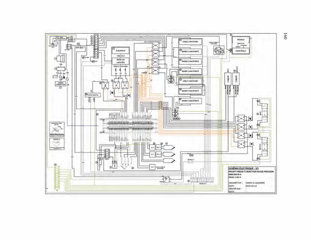
160
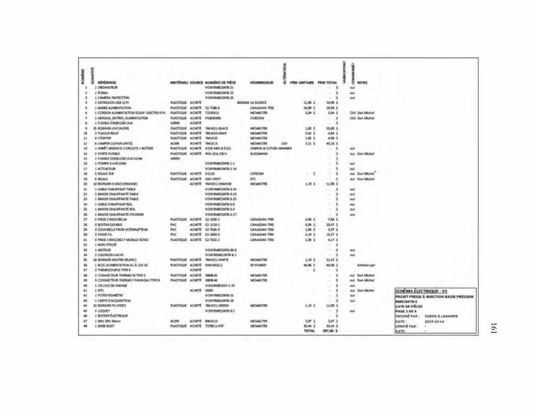
161 161
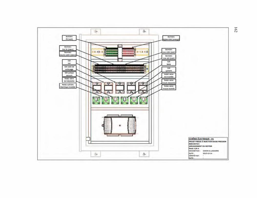
162 162
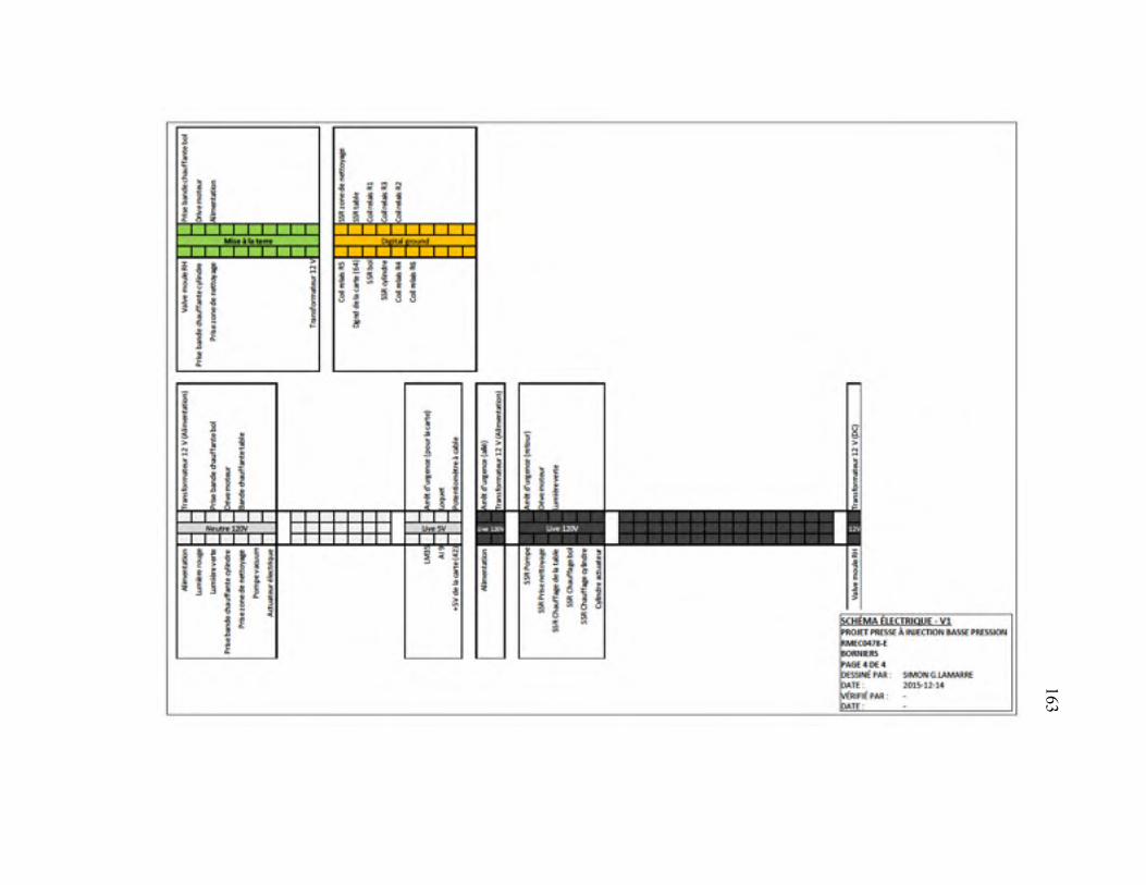
163 163

ANNEXE V
ARTICLE DE CONFÉRENCE MONTREAL’2016 AES-ATEMA
EXPERIMENTAL STUDY OF THE RHEOLOGICAL PROPERTIES AND MOLDABILITY OF WAX-BASED FEEDSTOCKS USED IN LOW-PRESSURE
POWDER INJECTION MOLDING
S. G. Lamarre 1, V. Demers 1*, J. F. Chatelain 1
1École de technologie supérieure, 1100 Notre-Dame West, Montreal, QC H3C 1K3, Canada
e-mail: Simon G. Lamarre ([email protected]); Jean-François Chatelain
*Corresponding author: Vincent Demers; Tel: 1 514 396-8590; Fax: 514 396-8530; E-mail:
Cette annexe a été présentée et publiée comme article lors de la conférence Montreal’2016
AES-ATEMA « Advances and Trends in Engineering Materials and their Applications ».
Présentée à Montréal le 22 juin 2016.
Abstract:
Low-pressure powder injection molding (LPIM) is an advanced manufacturing technology
used for the cost-effective and small series fabrication of complex net-shape components
with the proper dimensional tolerances. This technology takes advantage of low-viscosity
feedstocks to achieve high moldability during the injection step. Metallic powder is mixed
with molten low molecular weight polymeric binder to obtain a feedstock which can be
injected in a complex shape cavity using a pressure generally lower than 1 MPa. The
objective of this study is to correlate the rheological properties of LPIM feedstocks with the
moldability, i.e., the capacity of the feedstocks to be injected into the mold cavity with few
defects, using real scale injections. In the framework of this study, a new injection concept
was introduced in a laboratory injection press to avoid the segregation problem that may be
encountered with the commercial LPIM press.
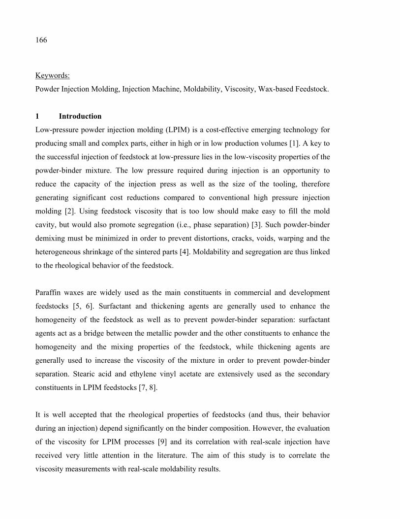
166
Keywords:
Powder Injection Molding, Injection Machine, Moldability, Viscosity, Wax-based Feedstock.
1 Introduction
Low-pressure powder injection molding (LPIM) is a cost-effective emerging technology for
producing small and complex parts, either in high or in low production volumes [1]. A key to
the successful injection of feedstock at low-pressure lies in the low-viscosity properties of the
powder-binder mixture. The low pressure required during injection is an opportunity to
reduce the capacity of the injection press as well as the size of the tooling, therefore
generating significant cost reductions compared to conventional high pressure injection
molding [2]. Using feedstock viscosity that is too low should make easy to fill the mold
cavity, but would also promote segregation (i.e., phase separation) [3]. Such powder-binder
demixing must be minimized in order to prevent distortions, cracks, voids, warping and the
heterogeneous shrinkage of the sintered parts [4]. Moldability and segregation are thus linked
to the rheological behavior of the feedstock.
Paraffin waxes are widely used as the main constituents in commercial and development
feedstocks [5, 6]. Surfactant and thickening agents are generally used to enhance the
homogeneity of the feedstock as well as to prevent powder-binder separation: surfactant
agents act as a bridge between the metallic powder and the other constituents to enhance the
homogeneity and the mixing properties of the feedstock, while thickening agents are
generally used to increase the viscosity of the mixture in order to prevent powder-binder
separation. Stearic acid and ethylene vinyl acetate are extensively used as the secondary
constituents in LPIM feedstocks [7, 8].
It is well accepted that the rheological properties of feedstocks (and thus, their behavior
during an injection) depend significantly on the binder composition. However, the evaluation
of the viscosity for LPIM processes [9] and its correlation with real-scale injection have
received very little attention in the literature. The aim of this study is to correlate the
viscosity measurements with real-scale moldability results.
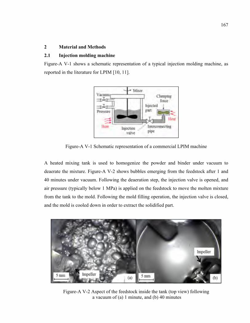
167
2 Material and Methods
2.1 Injection molding machine
Figure-A V-1 shows a schematic representation of a typical injection molding machine, as
reported in the literature for LPIM [10, 11].
Figure-A V-1 Schematic representation of a commercial LPIM machine
A heated mixing tank is used to homogenize the powder and binder under vacuum to
deaerate the mixture. Figure-A V-2 shows bubbles emerging from the feedstock after 1 and
40 minutes under vacuum. Following the deaeration step, the injection valve is opened, and
air pressure (typically below 1 MPa) is applied on the feedstock to move the molten mixture
from the tank to the mold. Following the mold filling operation, the injection valve is closed,
and the mold is cooled down in order to extract the solidified part.
Figure-A V-2 Aspect of the feedstock inside the tank (top view) following a vacuum of (a) 1 minute, and (b) 40 minutes
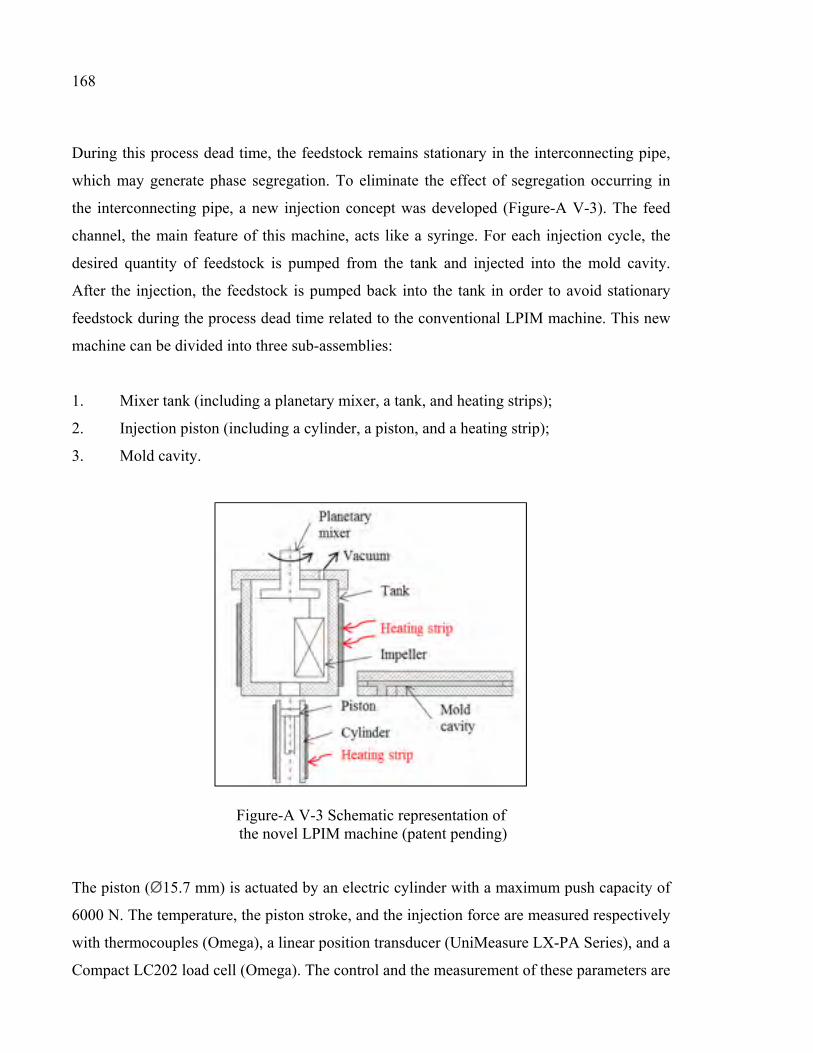
168
During this process dead time, the feedstock remains stationary in the interconnecting pipe,
which may generate phase segregation. To eliminate the effect of segregation occurring in
the interconnecting pipe, a new injection concept was developed (Figure-A V-3). The feed
channel, the main feature of this machine, acts like a syringe. For each injection cycle, the
desired quantity of feedstock is pumped from the tank and injected into the mold cavity.
After the injection, the feedstock is pumped back into the tank in order to avoid stationary
feedstock during the process dead time related to the conventional LPIM machine. This new
machine can be divided into three sub-assemblies:
1. Mixer tank (including a planetary mixer, a tank, and heating strips);
2. Injection piston (including a cylinder, a piston, and a heating strip);
3. Mold cavity.
Figure-A V-3 Schematic representation of the novel LPIM machine (patent pending)
The piston (Ø15.7 mm) is actuated by an electric cylinder with a maximum push capacity of
6000 N. The temperature, the piston stroke, and the injection force are measured respectively
with thermocouples (Omega), a linear position transducer (UniMeasure LX-PA Series), and a
Compact LC202 load cell (Omega). The control and the measurement of these parameters are
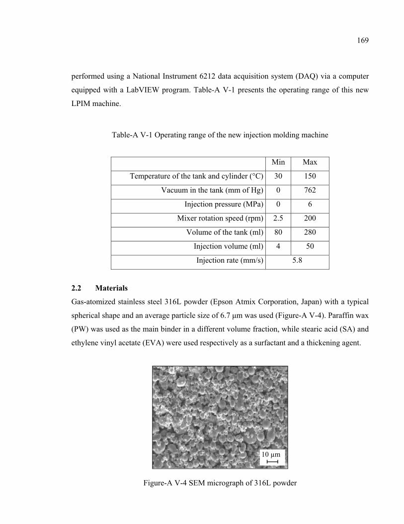
169
performed using a National Instrument 6212 data acquisition system (DAQ) via a computer
equipped with a LabVIEW program. Table-A V-1 presents the operating range of this new
LPIM machine.
Table-A V-1 Operating range of the new injection molding machine
Min Max
Temperature of the tank and cylinder (°C) 30 150
Vacuum in the tank (mm of Hg) 0 762
Injection pressure (MPa) 0 6
Mixer rotation speed (rpm) 2.5 200
Volume of the tank (ml) 80 280
Injection volume (ml) 4 50
Injection rate (mm/s) 5.8
2.2 Materials
Gas-atomized stainless steel 316L powder (Epson Atmix Corporation, Japan) with a typical
spherical shape and an average particle size of 6.7 μm was used (Figure-A V-4). Paraffin wax
(PW) was used as the main binder in a different volume fraction, while stearic acid (SA) and
ethylene vinyl acetate (EVA) were used respectively as a surfactant and a thickening agent.
Figure-A V-4 SEM micrograph of 316L powder
10 µm
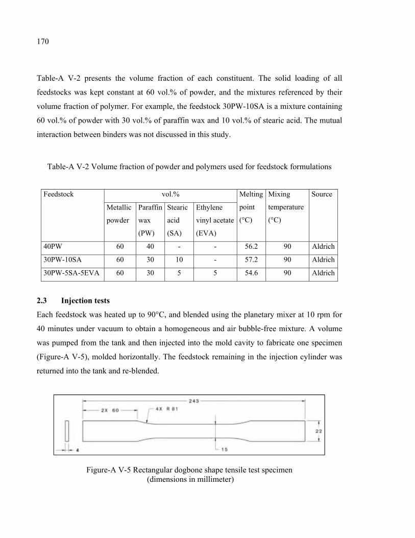
170
Table-A V-2 presents the volume fraction of each constituent. The solid loading of all
feedstocks was kept constant at 60 vol.% of powder, and the mixtures referenced by their
volume fraction of polymer. For example, the feedstock 30PW-10SA is a mixture containing
60 vol.% of powder with 30 vol.% of paraffin wax and 10 vol.% of stearic acid. The mutual
interaction between binders was not discussed in this study.
Table-A V-2 Volume fraction of powder and polymers used for feedstock formulations
Feedstock
vol.% Melting
point
(°C)
Mixing
temperature
(°C)
Source
Metallic
powder
Paraffin
wax
(PW)
Stearic
acid
(SA)
Ethylene
vinyl acetate
(EVA)
40PW 60 40 - - 56.2 90 Aldrich
30PW-10SA 60 30 10 - 57.2 90 Aldrich
30PW-5SA-5EVA 60 30 5 5 54.6 90 Aldrich
2.3 Injection tests
Each feedstock was heated up to 90°C, and blended using the planetary mixer at 10 rpm for
40 minutes under vacuum to obtain a homogeneous and air bubble-free mixture. A volume
was pumped from the tank and then injected into the mold cavity to fabricate one specimen
(Figure-A V-5), molded horizontally. The feedstock remaining in the injection cylinder was
returned into the tank and re-blended.
Figure-A V-5 Rectangular dogbone shape tensile test specimen (dimensions in millimeter)
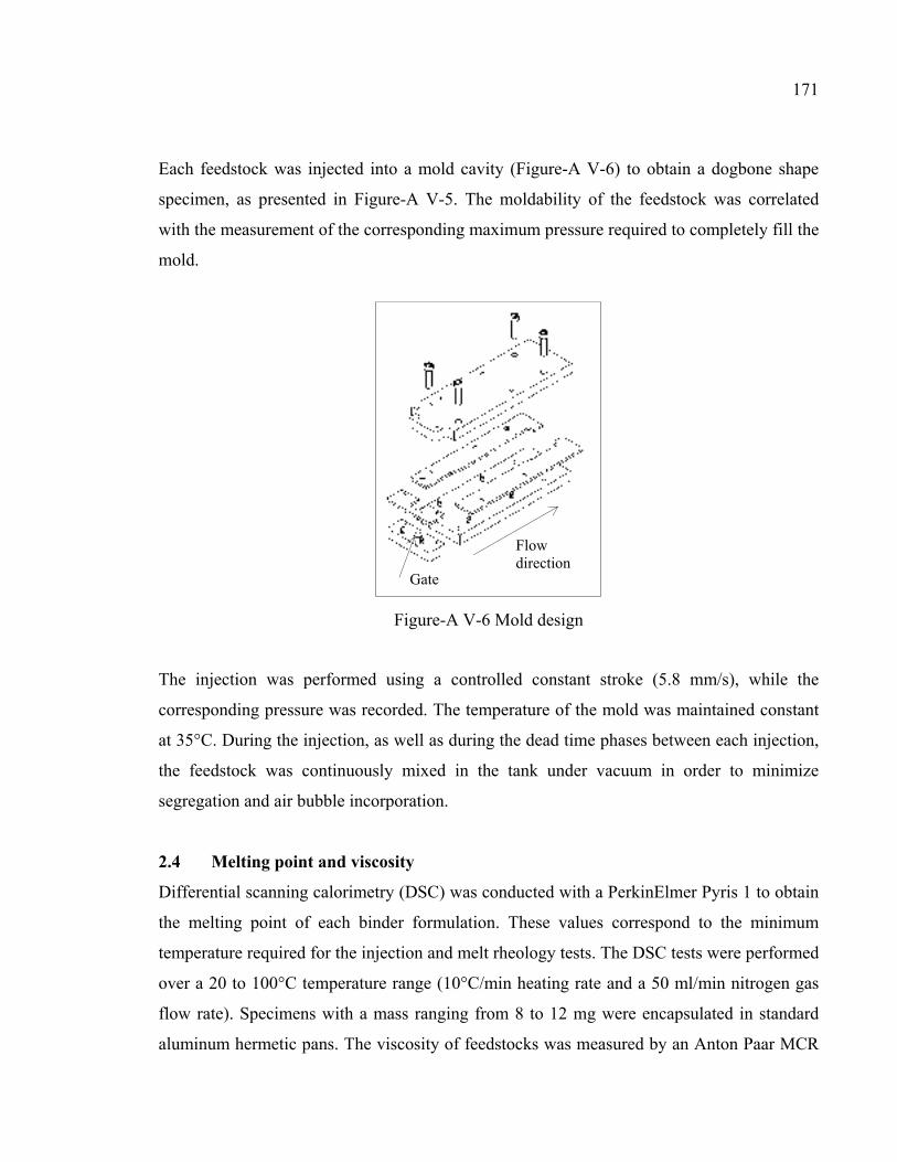
171
Each feedstock was injected into a mold cavity (Figure-A V-6) to obtain a dogbone shape
specimen, as presented in Figure-A V-5. The moldability of the feedstock was correlated
with the measurement of the corresponding maximum pressure required to completely fill the
mold.
Figure-A V-6 Mold design
The injection was performed using a controlled constant stroke (5.8 mm/s), while the
corresponding pressure was recorded. The temperature of the mold was maintained constant
at 35°C. During the injection, as well as during the dead time phases between each injection,
the feedstock was continuously mixed in the tank under vacuum in order to minimize
segregation and air bubble incorporation.
2.4 Melting point and viscosity
Differential scanning calorimetry (DSC) was conducted with a PerkinElmer Pyris 1 to obtain
the melting point of each binder formulation. These values correspond to the minimum
temperature required for the injection and melt rheology tests. The DSC tests were performed
over a 20 to 100°C temperature range (10°C/min heating rate and a 50 ml/min nitrogen gas
flow rate). Specimens with a mass ranging from 8 to 12 mg were encapsulated in standard
aluminum hermetic pans. The viscosity of feedstocks was measured by an Anton Paar MCR
Gate
Flowdirection
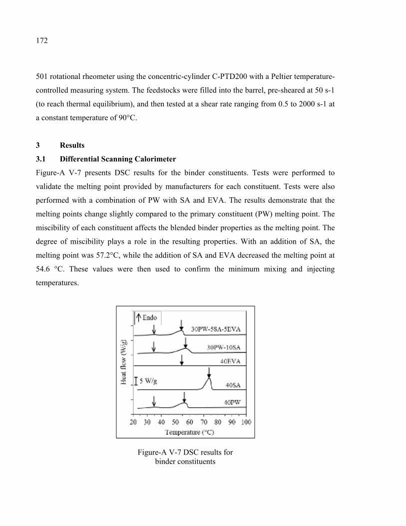
172
501 rotational rheometer using the concentric-cylinder C-PTD200 with a Peltier temperature-
controlled measuring system. The feedstocks were filled into the barrel, pre-sheared at 50 s-1
(to reach thermal equilibrium), and then tested at a shear rate ranging from 0.5 to 2000 s-1 at
a constant temperature of 90°C.
3 Results
3.1 Differential Scanning Calorimeter
Figure-A V-7 presents DSC results for the binder constituents. Tests were performed to
validate the melting point provided by manufacturers for each constituent. Tests were also
performed with a combination of PW with SA and EVA. The results demonstrate that the
melting points change slightly compared to the primary constituent (PW) melting point. The
miscibility of each constituent affects the blended binder properties as the melting point. The
degree of miscibility plays a role in the resulting properties. With an addition of SA, the
melting point was 57.2°C, while the addition of SA and EVA decreased the melting point at
54.6 °C. These values were then used to confirm the minimum mixing and injecting
temperatures.
Figure-A V-7 DSC results for binder constituents
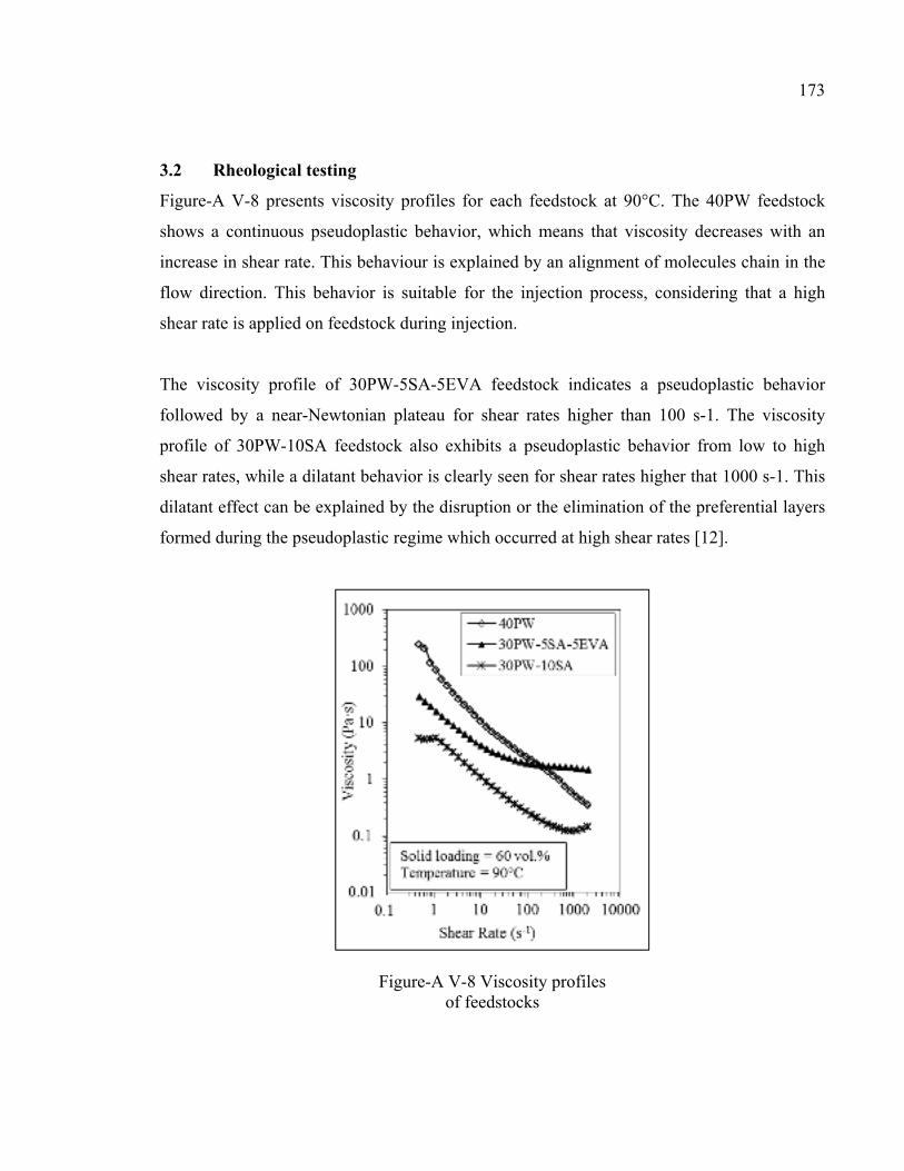
173
3.2 Rheological testing
Figure-A V-8 presents viscosity profiles for each feedstock at 90°C. The 40PW feedstock
shows a continuous pseudoplastic behavior, which means that viscosity decreases with an
increase in shear rate. This behaviour is explained by an alignment of molecules chain in the
flow direction. This behavior is suitable for the injection process, considering that a high
shear rate is applied on feedstock during injection.
The viscosity profile of 30PW-5SA-5EVA feedstock indicates a pseudoplastic behavior
followed by a near-Newtonian plateau for shear rates higher than 100 s-1. The viscosity
profile of 30PW-10SA feedstock also exhibits a pseudoplastic behavior from low to high
shear rates, while a dilatant behavior is clearly seen for shear rates higher that 1000 s-1. This
dilatant effect can be explained by the disruption or the elimination of the preferential layers
formed during the pseudoplastic regime which occurred at high shear rates [12].
Figure-A V-8 Viscosity profiles of feedstocks
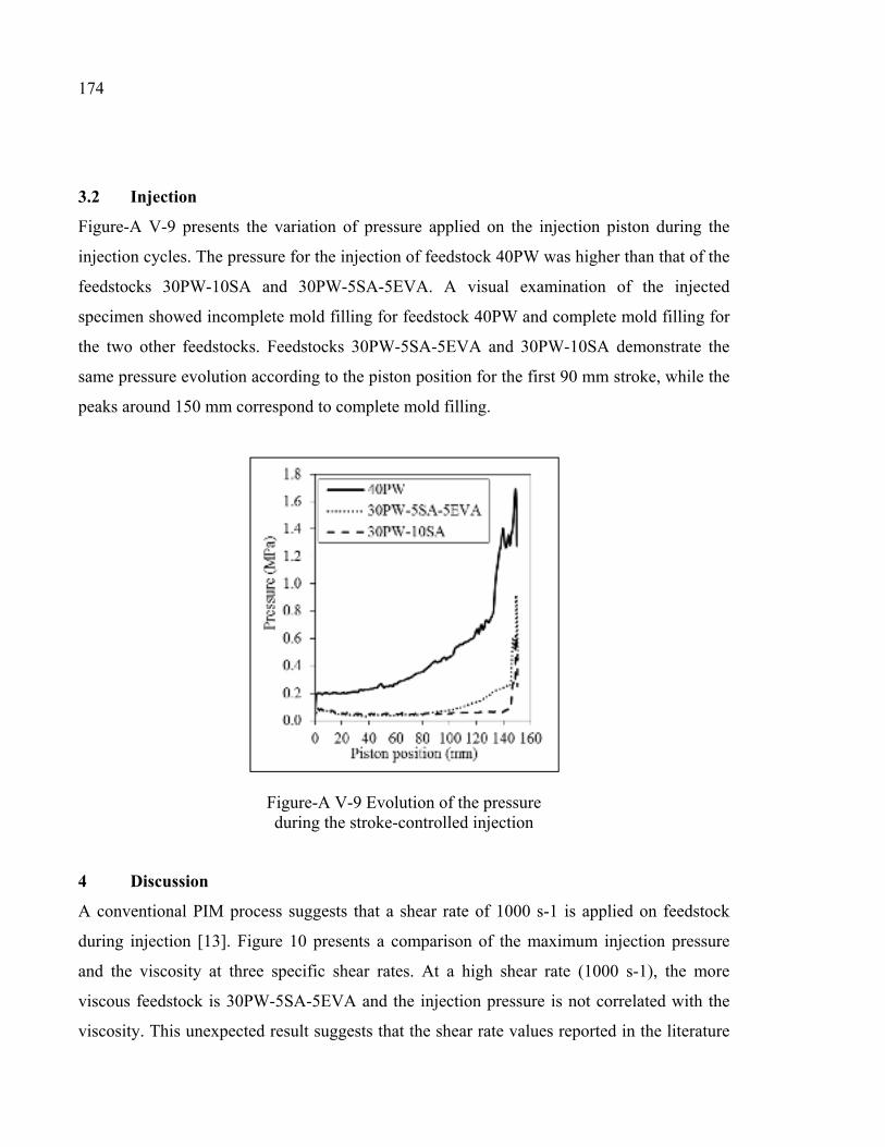
174
3.2 Injection
Figure-A V-9 presents the variation of pressure applied on the injection piston during the
injection cycles. The pressure for the injection of feedstock 40PW was higher than that of the
feedstocks 30PW-10SA and 30PW-5SA-5EVA. A visual examination of the injected
specimen showed incomplete mold filling for feedstock 40PW and complete mold filling for
the two other feedstocks. Feedstocks 30PW-5SA-5EVA and 30PW-10SA demonstrate the
same pressure evolution according to the piston position for the first 90 mm stroke, while the
peaks around 150 mm correspond to complete mold filling.
Figure-A V-9 Evolution of the pressure during the stroke-controlled injection
4 Discussion
A conventional PIM process suggests that a shear rate of 1000 s-1 is applied on feedstock
during injection [13]. Figure 10 presents a comparison of the maximum injection pressure
and the viscosity at three specific shear rates. At a high shear rate (1000 s-1), the more
viscous feedstock is 30PW-5SA-5EVA and the injection pressure is not correlated with the
viscosity. This unexpected result suggests that the shear rate values reported in the literature
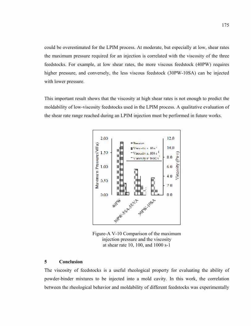
175
could be overestimated for the LPIM process. At moderate, but especially at low, shear rates
the maximum pressure required for an injection is correlated with the viscosity of the three
feedstocks. For example, at low shear rates, the more viscous feedstock (40PW) requires
higher pressure, and conversely, the less viscous feedstock (30PW-10SA) can be injected
with lower pressure.
This important result shows that the viscosity at high shear rates is not enough to predict the
moldability of low-viscosity feedstocks used in the LPIM process. A qualitative evaluation of
the shear rate range reached during an LPIM injection must be performed in future works.
Figure-A V-10 Comparison of the maximum injection pressure and the viscosity at shear rate 10, 100, and 1000 s-1
5 Conclusion
The viscosity of feedstocks is a useful rheological property for evaluating the ability of
powder-binder mixtures to be injected into a mold cavity. In this work, the correlation
between the rheological behavior and moldability of different feedstocks was experimentally
176
investigated. Rotational rheometer and a new injection press concept were used to measure
the viscosity and injection pressure on 316L stainless steel feedstocks.
The pressure required for the injection of feedstock containing only paraffin wax (40PW)
was higher than that of the feedstocks containing paraffin wax, surfactant and thickening
agents (30PW-10SA or 30PW-5SA-5EVA). In that respect, a visual examination of the
injected specimen showed incomplete mold filling for feedstock 40PW and complete mold
filling for the two other feedstocks. It was also seen that the injection pressure values were
unexpectedly correlated with the viscosity obtained at low shear rates instead of high shear
rates. This result suggests that the shear rate values reported for a conventional PIM process
may not be used directly in the LPIM process.
Acknowledgments
This work was carried out with the financial support of the École de technologie supérieure.
References
[1] Medvedovski, E., Peltsman, M. (2012) Low pressure injection moulding mass production technology of complex shape advanced ceramic components, Advances in Applied Ceramics, 111 (5-6), 333-344.
[2] Krindges, I., Andreola, R., Perottoni, C. A., Zorzi, J. E. (2008) Low-pressure injection
molding of ceramic springs, International Journal of Applied Ceramic Technology, 5 (3), 243-248.
[3] Demers, V., Turenne, S., Scalzo, O. (2015) Segregation measurement of powder
injection molding feedstock using thermogravimetric analysis, pycnometer density and differential scanning calorimetry techniques, Advanced Powder Technology, 26 (3), 997-1004.
[4] Barriere, T., Liu, B., Gelin, J. C. (2002) Analyses of powder segregation in MIM,
Metal Powder Report, 57 (5), 30-33. [5] Ikegami, R. A., Purquerio, B. D. M. (2001) Low pressure injection moulding of
stainless steel powder, Key Engineering Materials, 189-191, 467-472. [6] Hidalgo, J., Abajo, C., Jiménez-Morales, A., Torralba, J. M. (2013) Effect of a binder
system on the low-pressure powder injection moulding of water-soluble zircon feedstocks, Journal of the European Ceramic Society, 33 (15–16), 3185-3194.
177
[7] Rei, M., Milke, E. C., Gomes, R. M., Schaeffer, L., Souza, J. P. (2002) Low-pressure injection molding processing of a 316-L stainless steel feedstock, Materials Letters, 52 (4–5), 360-365.
[8] Li, Y.-m., Liu, X.-q., Luo, F.-h., Yue, J.-l. (2007) Effects of surfactant on properties
of MIM feedstock, Transactions of the Nonferrous Metals Society of China, 17 (1), 1-8.
[9] Demers, V., Turenne, S., Scalzo, O. (2015) Impact of binders on viscosity of low-
pressure powder injection molded Inconel 718 superalloy, Journal of Materials Science, 50 (7), 2893-2902.
[10] Peltsman, M. I., Peltsman, I. D. November 22, 1983. Low pressure hot molding
machine. US Pat. 4,416,603. In PatFT. USPTO. [11] Goncalves, A. C. (2001) Metallic powder injection molding using low pressure,
Journal of Materials Processing Technology, 118, 193-198. [12] Hausnerova, B., Marcanikova, L., Filip, P., Saha, P. (2011) Optimization of powder
injection molding of feedstock based on aluminum oxide and multicomponent water-soluble polymer binder, Polymer Engineering and Science, 51 (7), 1376-1382.
[13] González-Gutiérrez, J., Stringari, G. B., Emri, I. (2012) Powder Injection Molding of
Metal and Ceramic Parts, Some Critical Issues for Injection Molding, Dr. Jian Wang (Ed.), 978-953.

LISTE DE RÉFÉRENCES BIBLIOGRAPHIQUES
Ahn, Seokyoung, Seong Jin Park, Shiwoo Lee, Sundar V. Atre et Randall M. German. 2009. « Effect of powders and binders on material properties and molding parameters in iron and stainless steel powder injection molding process ». Powder Technology, vol. 193, no 2, p. 162-169.
Arifin, Amir, Abu Bakar Sulong, Norhamidi Muhamad, Junaidi Syarif et Mohd Ikram Ramli.
2015. « Powder injection molding of HA/Ti6Al4V composite using palm stearin as based binder for implant material ». Materials and Design, vol. 65, p. 1028-34.
Aslam, Muhammad, Faiz Ahmad, Puteri Sri Melor Binti Megat Yusoff, Khurram Altaf,
Mohd Afian Omar, H. P. S. Abdul Khalil et M. Rafi Raza. 2016. « Investigation of Rheological Behavior of Low Pressure Injection Molded Stainless Steel Feedstocks ». Advances in Materials Science and Engineering, vol. 2016.
ASTM. 2013. Standard Test Methods for Tension Testing of Metallic Materials. E8/E8M-
13a: ASTM International, 28 p. Bilovol, V. V., L. Kowalski, J. Duszczyk et L. Katgerman. 2006. « The effect of constitutive
description of PIM feedstock viscosity in numerical analysis of the powder injection moulding process ». Journal of Materials Processing Technology, vol. 178, no 1-3, p. 194-9.
Çengel, Y.A., et J.M. Cimbala. 2006. Fluid Mechanics: Fundamentals and Applications.
McGraw-Hill Higher Education, 994 p. Demers, Vincent, Sylvain Turenne et Orlando Scalzo. 2015. « Segregation measurement of
powder injection molding feedstock using thermogravimetric analysis, pycnometer density and differential scanning calorimetry techniques ». Advanced Powder Technology, vol. 26, no 3, p. 997-1004.
Dvorak, P., T. Barriere et Jean-Claude Gelin. 2005. « Jetting in metal injection moulding of
316L stainless steel ». Powder Metallurgy, vol. 48, no 3, p. 254-260. Fareh, F., V. Demers, S. Turenne et O. Scalzo. 2016. « Segregation measurement of inconel
718 feedstocks used in low-pressure metal injection molding ». In International Conference on Advanced Materials Engineering and Technology, ICAMET 2015, December 4, 2015 - December 5, 2015. (Kaohsiung, Taiwan) Vol. 857, p. 286-290. Coll. « Materials Science Forum »: Trans Tech Publications Ltd.
German, R.M., et A. Bose (413). 1997. Injection Molding of Metals and Ceramics. Metal
Powder Industries Federation.
180
Goncalves, Aparecido Carlos. 2001. « Metallic powder injection molding using low pressure ». Journal of Materials Processing Technology, vol. 118, p. 193-198.
González-Gutiérrez, Joamín, Gustavo Beulke Stringari et Igor Emri. 2012. « Powder
Injection Molding of Metal and Ceramic Parts ». Some Critical Issues for Injection Molding, Dr. Jian Wang (Ed.), p. 978-953.
Hausnerova, Berenika, Lucie Marcanikova, Petr Filip et Petr Saha. 2011. « Optimization of
powder injection molding of feedstock based on aluminum oxide and multicomponent water-soluble polymer binder ». Polymer Engineering and Science, vol. 51, no 7, p. 1376-1382.
Hausnerova, Berenika, Tomas Sedlacek, Radek Slezak et Petr Saha. 2005. « Pressure-
dependent viscosity of powder injection moulding compounds ». Rheologica Acta, vol. 45, no 3, p. 290-296.
Heaney, D. F. 2012a. « 2 - Designing for metal injection molding (MIM) ». In Handbook of
Metal Injection Molding, sous la dir. de Heaney, Donald F., p. 29-49. Woodhead Publishing.
Heaney, D. F. 2012b. « 3 - Powders for metal injection molding (MIM) ». In Handbook of
Metal Injection Molding, sous la dir. de Heaney, Donald F., p. 50-63. Woodhead Publishing.
Heaney, D. F. 2012c. Handbook of Metal Injection Molding, 1st ed. Woodhead Publishing,
604 p. Hidalgo, J., C. Abajo, A. Jiménez-Morales et J. M. Torralba. 2013. « Effect of a binder
system on the low-pressure powder injection moulding of water-soluble zircon feedstocks ». Journal of the European Ceramic Society, vol. 33, no 15–16, p. 3185-3194.
Ibrahim, M. H. I., N. Muhamad et A. B. Sulong. 2011. « Rheological Characterization of
Water Atomised Stainless Steel SS316L for Micro MIM ». Advanced Materials Research, vol. 264-265, no 1, p. 129-34.
Ibrahim, R., M. Azmirruddin, M. Jabir, N. Johari, M. Muhamad et A. R. A. Talib. 2014. «
Effect of solid loading on the physical properties of the sintered inconel 718 using metal injection moulding (MIM) ». In Advanced Materials Conference, AMC 2012, December 12, 2012 - December 13, 2012. (Langkawi, Malaysia) Vol. 879, p. 164-168. Coll. « Advanced Materials Research »: Trans Tech Publications Ltd.
Ivzhenko, V. V., V. A. Popov et G. F. Sarnavskaya. 2012. « Powder metallurgy industry and
managerial economics micro/nanosized refractory powder injection molding machine ». Powder Metallurgy and Metal Ceramics, vol. 51, no 5-6, p. 368-371.
181
Jenni, Martin, Rudolf Zauner, Juergen Stampfl et Jeff Morris. 2008. « Quantitative study of
process and material parameters on flow behavior and powder binder separation of feedstocks: Experimental design 3d simulation model and balance model for separation in suspensions ». In 2008 World Congress on Powder Metallurgy and Particulate Materials, PowderMet 2008, June 8, 2008 - June 12, 2008. (Washington, DC, United states), p. 1169-1178. Coll. « Advances in Powder Metallurgy and Particulate Materials - 2008, Proceedings of the 2008 World Congress on Powder Metallurgy and Particulate Materials, PowderMet 2008 »: Metal Powder Industries Federation.
Jenni, Martin, Rudolf Zauner et Jurgen Stampfl. 2009. « Measurement methods for powder
binder separation in PIM components ». In European International Powder Metallurgy Congress and Exhibition, Euro PM 2009, October 12, 2009 - October 14, 2009. (Copenhagen, Denmark) Vol. 2. Coll. « Proceedings of the Euro International Powder Metallurgy Congress and Exhibition, Euro PM 2009 »: European Powder Metallurgy Association (EPMA).
Karatas, C., A. Sozen, E. Arcaklioglu et S. Erguney. 2008. « Investigation of mouldability
for feedstocks used powder injection moulding ». Materials and Design, vol. 29, no 9, p. 1713-24.
Keizo, Y. 1989. Injection molding method and injection molding device of ceramics. Kryachek, ViktorM. 2004. « Injection Moulding (Review) ». Powder Metallurgy and Metal
Ceramics, vol. 43, no 7-8, p. 336-348. Lee, S. W., Park Seong Jin et R. M. German. 2011. « Issues and trends in powder injection
molding research and applications ». In International Conference on Advanced Manufacturing Technology 2011 (ATDM 2011), 3-5 Nov. 2011. (Stevenage, UK), p. 56-61. Coll. « Proceedings of the International Conference on Advanced Manufacturing Technology 2011 (ATDM 2011) »: IET.
Li, Y., Li Liujun et K. A. Khalil. 2007. « Effect of powder loading on metal injection
molding stainless steels ». Journal of Materials Processing Technology, vol. 183, no 2-3, p. 432-9.
Li, Yi-min, Xiang-quan Liu, Feng-hua Luo et Jian-ling Yue. 2007. « Effects of surfactant on
properties of MIM feedstock ». Transactions of the Nonferrous Metals Society of China, vol. 17, no 1, p. 1-8.
Loebbecke, Birgit, Regina Knitter et Jürgen Haußelt. 2009. « Rheological properties of
alumina feedstocks for the low-pressure injection moulding process ». Journal of the European Ceramic Society, vol. 29, no 9, p. 1595-1602.
182
Mangels, John A. 1994. « Low-pressure injection molding ». American Ceramic Society Bulletin, vol. 73, no 5, p. 37-41.
Mannschatz, A., A. Muller et T. Moritz. 2011. « Influence of powder morphology on
properties of ceramic injection moulding feedstocks ». Journal of the European Ceramic Society, vol. 31, no 14, p. 2551-8.
Medvedovski, E., et M. Peltsman. 2012. « Low pressure injection moulding mass production
technology of complex shape advanced ceramic components ». Advances in Applied Ceramics, vol. 111, no 5-6, p. 333-344.
NKK Corporation. 1989. Method for casting powder into a compact and apparatus therefor.
EP 0 316 541 A1. Office européen des brevets. < http://www.google.com/patents/EP0316541A1?cl=en >. Consulté le 5 juin 2016.
Peltsman, M.I. Peltsman, I.D. 1983. Low pressure hot molding machine. US Pat. 4,416,603. In PatFT.
Online. < http://patft.uspto.gov/netacgi/nph-Parser?Sect1=PTO1&Sect2=HITOFF&d=PALL&p=1&u=%2Fnetahtml%2FPTO%2Fsrchnum.htm&r=1&f=G&l=50&s1=4,416,603.PN.&OS=PN/4,416,603&RS=PN/4,416,603 >. Consulté le 13 avril 2016.
Peltsman, Michael. 1986. « Low pressure injection moulding and mould design ». Metal
Powder Report, vol. 41, no 5, p. 367-369. Pompe, R., et J. Brandt. 2001. « Goceram's MEDPIMOULD technology offers cost-effective
PIM production ». Metal Powder Report, vol. 56, no 6, p. 14-17. Sack, Rainer, et Klaus-Dieter Lietzmann. 1990. « Basic principles of low-pressure injection
moulding and experience with the process ». International Journal of Materials and Product Technology, vol. 8, no 2-4, p. 371-380.
Schlechtriemen, N., R. Knitter, J. Haucelt et J. R. Binder. 2013. « Impact of powder
morphology on quality of low-pressure injection moulded reaction-bonded net shape oxide ceramics ». Journal of the European Ceramic Society, vol. 33, no 4, p. 709-15.
Schlieper, G. 2012. « 5 - Tooling for metal injection molding (MIM) ». In Handbook of
Metal Injection Molding, sous la dir. de Heaney, Donald F., p. 93-109e. Woodhead Publishing. In Google Patent.
Sotomayor, M. E., A. Varez et B. Levenfeld. 2010. « Influence of powder particle size
distribution on rheological properties of 316 L powder injection moulding feedstocks ». Powder Technology, vol. 200, no 1-2, p. 30-6.
183
Vervoort, P. J., R. Vetter et J. Duszczyk. 1996. « Overview of powder injection molding ». Advanced Performance Materials, vol. 3, no 2, p. 121-151.
Honda Giken Kogyo Kabushiki Kaisha. 1998. Apparatus for supplying inorganic slurry to an
injection mold. 5,795,601. In Google Patent. Google. < https://www.google.ca/patents/US5795601 >. Consulté le 5 juin 2016.
Zorzi, J. E., C. A. Perottoni et J. A. H. Da Jornada. 2003. « Wax-based binder for low-
pressure injection molding and the robust production of ceramic parts ». Industrial Ceramics, vol. 23, no 1, p. 47-49.