Embed Size (px)
Citation preview
applied sciences
Article
CPES Testing with MOSAIK Co-Simulation PlanningExecution and Analysis
Cornelius Steinbrink 1dagger Marita Blank-Babazadeh 1dagger Andreacute El-Ama 1dagger Stefanie Holly 1daggerBengt Luumlers 1dagger Marvin Nebel-Wenner 1dagger Rebeca P Ramiacuterez Acosta 1dagger Thomas Raub 1daggerJan Soumlren Schwarz 2dagger Sanja Stark 1dagger Astrid Nieszlige 3dagger and Sebastian Lehnhoff 1dagger
1 OFFISmdashInstitute for Information Technology Escherweg 2 26121 Oldenburg Germanymaritablank-babazadehoffisde (MB-B) andreel-amaoffisde (AE-A) stefaniehollyoffisde (SH)bengtlueersoffisde (BL) marvinnebel-wenneroffisde (MN-W) rebecaramirezoffisde (RPRA)thomasrauboffisde (TR) sanjastarkoffisde (SS) sebastianlehnhoffoffisde (SL)
2 Department of Computer Science University of Oldenburg Ammerlaumlnder Heerstraszlige 114-11826129 Oldenburg Germany jansoerenschwarzuolde
3 Group Energy Informatics Leibniz University Hannover Appelstraszlige 9a 30167 Hannover Germanyniesseeiuni-hannoverde
Correspondence corneliussteinbrinkoffisde Tel +49-441-9722-404dagger These authors contributed equally to this work
Received 19 January 2019 Accepted 26 February 2019 Published 5 March 2019
Abstract The complex nature of cyber-physical energy systems (CPES) makes systematic testingof new technologies for these setups challenging Co-simulation has been identified as an efficientand flexible test approach that allows consideration of interdisciplinary dynamic interactionsHowever basic coupling of simulation models alone fails to account for many of the challenges ofsimulation-based multi-domain testing such as expert collaboration in test planning This paperillustrates an extended CPES test environment based on the co-simulation framework MOSAIKThe environment contains capabilities for simulation planning uncertainty quantification and thedevelopment of multi-agent systems An application case involving virtual power plant controlis used to demonstrate the platformrsquos features Future extensibility of the highly modular testenvironment is outlined
Keywords testing co-simulation MOSAIK multi-agent systems simulation planning uncertaintyquantification
1 Introduction
A cyber-physical energy system (CPES) is an example of so-called systems of systemsIts dynamical behavior emerges from the interactions of various complex components and systemsthat themselves may display nonlinear dynamics Additionally CPES unite formerly separate domainsfrom the physical energy systems eg electric power grids distributed energy resources (DER) or heatand gas networks with the digital world of information and communication infrastructure (ICT)data privacy and cyber-security But also human behavior plays an important role be it from aneconomic point of view with energy markets or through the social aspects of consumption behaviorSuch human-driven systems are sometimes called transactive energy systems or H-CPES but in thecontext of this paper social and economic dynamics are included in the understanding of CPESFurthermore environmental factors play an important role in the forcing (weather) as well as theassessment (sustainability) of CPES Therefore CPES should also be considered in regard to theirresponse to meteorological events or techno-environmental feedback
Appl Sci 2019 9 923 doi103390app9050923 wwwmdpicomjournalapplsci
Appl Sci 2019 9 923 2 of 20
One of the major challenges of designing and implementing CPES lies in the development andtesting of technologies and concepts to guarantee functionality stability and safety during operationThis is especially true for CPES components with complex behavior and many interfaces with differentdomains Due to this complexity and interdisciplinarity analytical testing on a formal basis is infeasiblefor CPES solutions (beyond the first conceptualization phase of new solutions) The alternativeapproach of hardware tests in laboratories or in the field is expensive and inflexible It is thus appliedonly in the last stages of development Therefore software simulation proves to be valuable as apreparatory test stage before hardware testing on the one hand as well as an easily scalable testenvironment that allows consideration of larger and more complex setups The role of simulation inthe development of eg smart grid algorithms has been discussed in detail in [1]
A type of simulation that has become popular in CPES testing is co-simulation (see [23]) It allowsusers to couple independent simulation tools representing different parts of the overall systemThis greatly reduces the modeling effort and error-proneness related to monolithic representationsof interdisciplinary systems The different components of a co-simulation setup (called ldquosimulatorsrdquoin the following) are interfaced with each other and exchange data during runtime so that asimulation process can work in a distributed manner and across heterogeneous runtime environmentsFurthermore generic co-simulation systems can be used to reduce the interfacing effort and increasethe transferability of solutions onto different application cases
Despite its advantages working with co-simulation involves a number of challenges A commonlydiscussed hurdle is the technical coupling of heterogeneous software tools Identifying the mostsuitable tools however is often overlooked Such a process requires experts and modelers fromdifferent domains to find a common understanding of their toolsrsquo capabilities and simulation goalsThis is often hindered by the lack of a domain-crossing language for CPES description Similarlyjoining knowledge from different domains will typically involve different degrees of simplificationand aggregation Therefore the quality and reliability of co-simulation outputs may vary over timeand may be difficult to assess even for simulation experts While these issues are widely recognized inthe CPES co-simulation community most approaches are so far focused on the more technical aspectsof simulator coupling
A popular standard for co-simulation is the functional mock-up interface (FMI) [4] whichdescribes the data and functions a simulator needs to provide in order to participate in a co-simulationSimulators interfaced via FMI still need a so-called co-simulation master that coordinates andsynchronizes the data exchange between them Several co-simulation frameworks exist alreadythat provide such a master algorithm often in combination with their own interfaces and furthercapabilities The standard high-level architecture (HLA) [5] provides the basis for some frameworkslike the CPS wind tunnel [6] Similarly the multi-paradigm simulation environment Ptolemy II [7] isalso sometimes employed in co-simulation (eg [8]) Newer frameworks involve the tool DACCOSIM[9] for distributed FMI-based simulation the agent-based framework MECSYCO [10] and the OpSimsystem [11] related to the simulation message bus (SMB) [12] concept The focus of this paper lies onthe open-source co-simulation framework MOSAIK (httpmosaikoffisde) that is used in its currentform since 2014
Comparing or even ranking co-simulation frameworks against each other is a challenging tasksince the diversity of possible application cases in the CPES domain requires or favors differentframework features in different situations Some attempts at framework classification and comparisoncan be found in [1314] Another simplified approach to assess frameworks is given by the threeattributes performance flexibility and usability All three points are important for a good frameworkbut practical experience suggests that no single one can be maximized without at least one of the otherattributes decreasing The authors thus suggest that the mentioned co-simulation frameworks filldifferent niches depending on the employed simulators modeled systems research goals and targetuser group
Appl Sci 2019 9 923 3 of 20
The MOSAIK framework is focused on providing high usability and flexibility It is thus mostsuitable for users that regularly need to set up different co-simulation experiments and probably workin interdisciplinary teams to conduct tests with a focus on multi-domain interactions Furthermorethe framework has been created with users in mind that are not necessarily co-simulation expertsThis is reflected by the core features of MOSAIK as well as additional modules and processes that helpusers among other things to plan their co-simulation experiments or assess their output accuracyThese modules tackle the challenges associated with the combination of tools and knowledge acrossdifferent domains as indicated above
One of the major purposes of the original MOSAIK design has been the evaluation of new forms ofICT solutions based on multi-agent systems (MAS) [15] In general MAS provide the possibility tomodel components and their interactions in different domains Example application areas are socialsciences with the evolution of societies [16] or pedestrian behaviour in transportation studies [17]But also in the domain of energy systems MAS have become popular [18] They can be used as controlmechanisms reaching from local to coordinated optimization and thus allow for distributed controlwith different objectives eg scheduling for market optimization or grid stability and therefore providemore flexibility and scalability Thus MAS solutions are especially beneficial regarding the growingcomplexity in CPES Due to the strong link between the MAS approach and MOSAIK the framework isintegrated with features for the development of distributed ICT solutions This aspect of the testingenvironment is elucidated further below
This paper makes a case for test environments that go beyond basic co-simulation frameworksbut in fact integrate toolchains for the realization of more mature and complex validation experimentsThis is done by presenting the current state of the MOSAIK environment including the core frameworkas well as its extended functionalities and associated tools The extended environment allows usersto not only solve the problem of technical simulator interoperability but actually face challengesassociated with cross-domain expert collaboration This involves tool selection and test planningresult reliability and development of novel control solutions for complex systems All this informationis provided with a focus of application in CPES development and testing The remainder of thepaper is structured as follows In Section 2 the main features of the MOSAIK environment areillustrated with Section 26 providing an exemplary application case Section 3 presents the resultsfrom the demonstration case with a focus on the benefits provided by the MOSAIK toolchain Section 4discusses the trade-offs made by the framework provides an overview of further application examplesand outlines future developments The paper is concluded with Section 5
2 Materials and Methods
This section gives an overview of the proposed CPES test environment with Section 21 displayingthe overall architecture While the MOSAIK framework as the core of the environment has already beenin use for some years the extended environment includes a number of new tools and concepts that havenot yet been described in combination Together they allow not only the coordination of heterogeneoussimulation models (Section 22) but also the structured planning of complex experiments (Section 23)analysis of their output accuracy (Section 24) and integration of distributed ICT solutions (Section 25)The setup presentation is concluded by the outlining of a demonstration case (Section 26) to illustratethe various capabilities of the environment
21 MOSAIK System Architecture
The MOSAIK co-simulation environment can be divided into three parts the core frameworkthe set of adapters and additional utility software The core provides the basic co-simulationfunctionality via a set of interconnected modules the central two being the sim-manager and thescheduler modules The sim-manager is responsible for setting up and maintaining the connectionsbetween MOSAIK and the simulators The scheduler on the other hand coordinates the data exchangebetween the simulators during runtime (see Section 22) A simulator is always an independently
Appl Sci 2019 9 923 4 of 20
executable piece of software that implements a simulation model For user interaction with MOSAIKtwo API are provided The component-API has to be used to establish an interface between MOSAIK
and a new simulator It specifies the socket connection used for data exchange and outlines what kindof data the simulator has to accept and provide The scenario-API on the other hand allows usersto set up executable co-simulation scenarios by specifying which simulators are to be used and howthey should be parameterized and interconnected with each other During execution a scenario scriptemploys the functionalities of the sim-manager and the scheduler An overview of the MOSAIK corearchitecture is provided in Figure 1
Component-API
Scenario-API
ScenarioScript
MO
SAIK
Cor
e Sim-Manager
Scheduler
calls
Set of API amp
adapters
MATLAB-API
FMI Adapter
Java-API
Set of already
integrated
simulators
PyPower
ISAAC
TCP connection
Implementations
calls
NewSimulator
Model
ComponentInterface
User-defined
connection
Providedimplemented
by user
implements
SimulationPlanning
UncertaintyQuantification GUI Utility
extensions
Part of the MOSAIK
environment
To be provided
by the user
Figure 1 Architecture overview of the full MOSAIK environment
While the MOSAIK software itself contains no simulation models there is a constantly growingset of simulators that are interfaced with the framework This is called the MOSAIK ecosystemAn important part of this ecosystem are open-source simulation tools that can be downloaded withthe basic MOSAIK setup eg the PyPower tool (based on the MatPower software [19]) The MAStool ISAAC is to be mentioned here (see Section 25) However a number of commercial tools arealso already supported by MOSAIK like PowerFactory or Opal-RT eMEGAsim [2021] Even moreso the component-API specification has been implemented in different programming languages(eg Python Java MATLAB) to facilitate the integration of a wide variety of different simulatorsAn FMI adapter is also given so that MOSAIK can serve as a master for all simulators that supportthe standard
To improve the usability and performance of MOSAIK additional software modules and processesare being developed to extend the capabilities of the system beyond data exchange schedulingbetween simulators The MOSAIK system architecture follows a modular approach in regard ofthese utility tools They build up on the co-simulation core but function as independent softwareThis way users of the co-simulation framework have the freedom to install only those additionalmodules which they actually like to employ The utility environment is comprised of a GUI fordemonstration and education purposes (httpsmaverigreadthedocsioquickstarthtml) processesfor simulation planning (Section 23) an uncertainty quantification system (Section 24) and is currentlybeing extended by modules for performance improvement via the application of surrogate modeling(Section 43)
Appl Sci 2019 9 923 5 of 20
22 Scheduling Algorithm
The scheduling paradigm employed by MOSAIK can be interpreted as a flexible discrete-timesimulation One of its basic concepts is the so-called data flow graph a directed graph that indicatesthe data dependencies between the simulators employed in the co-simulation The graph is establishedautomatically at the beginning of a co-simulation process Its structure is based on the connectionsbetween simulators that are defined by a user via the scenario-API in a scenario script For eachsimulator S the graph indicates which other simulators provide S with data (predecessors) and whichrequire data from S (successors) After the graph is established an individual simulation process isstarted for each employed simulator The structure of such a process is depicted in Figure 2
keeprunning
steprequired
wait for
dependencies
wake uppredecessors
get input data
step
get outputs
yes
yesno
no
condition
event
sync func
async func
Figure 2 Simulation process for an individual simulator
The process for a given simulator is structured in steps that indicate its temporal progression The stepsize is measured in integers to guarantee comparability between the timing of different simulatorsThe simulation process iterates for each simulator each time performing a step until the end of theco-simulation is reached The data exchange between simulators is conducted asynchronously to improveco-simulation performance
At the beginning of each simulation process iteration it is checked whether a new simulationstep is required If the end of the co-simulation is reached or all predecessors have stopped alreadythe simulator in question is stopped Right before stopping the simulator triggers its (unstopped)predecessors to allow them to check whether they can also stop Unstopped simulators continue withtheir simulation process and check whether a simulation step is currently expected from them This istrue if the simulator in questions possesses no successors or if any successor is currently waiting fordata input A simulator that requires a next step then checks whether it needs input data from itspredecessors and waits if that is the case In other words waiting for input data can propagate acrossdifferent simulation processes until a simulator with no open dependencies provides the initiallyneeded data
The waiting between simulation processes is managed via the discrete event simulation (DES)framework Simpy (httpssimpyreadthedocsioenlatest) This framework enables the creation ofwait events to pause processes and trigger them again if certain conditions are resolved (typically dataavailability) This allows for efficient management of the timing of asynchronous simulation processes
The actual data exchange between a simulator and MOSAIK is divided into three stages Firstthe input data required by the simulator is read from MOSAIKrsquos internal buffer and put into thesimulatorrsquos input buffer The data requirement is specified via the data flow graph Furthermore
Appl Sci 2019 9 923 6 of 20
the data in the MOSAIK buffer is associated with timestamps to make sure that only valid data isprovided After the data provision the actual simulation step for the simulator is performed by callingthe appropriate function of the simulator interface All data within the simulatorrsquos input buffer aswell as its current step time is provided as input Stepping triggers calculations of the simulator andadvances it in time The call is conducted asynchronously so that it does not needlessly block theoverall co-simulation As a response to the call the simulator provides its next time step This waysimulators can adjust their temporal resolution during execution and are not bound to one fixed stepsize After the step execution finally the simulator receives an asynchronous request for all outputdata its successors expect The data is stored in the MOSAIK buffer This allows for the reuse of old datawithout the need to request it again from the simulator Such a feature can be useful if two simulatorswith different temporal resolution are coupled In order to prevent storage overflow the buffer isregularly pruned After the data has been provided all of the simulatorrsquos successors are triggeredThey can then check whether all their required input data is available and they can proceed with theirsimulation process
The scheduling algorithm in its presented form only works for data exchange in one directionIf two simulators require data from each other deadlocks can paralyze the co-simulation In orderto avoid this a second data flow graph is introduced that handles the second direction of thesedata flow cycles To avoid conflicts the dependencies of the second graph are always resolvedafter those of the first graph In other words cycles are broken by a shift in time A more detaileddescription about this and other aspects of the MOSAIK core can be found in the online documentation(httpsmosaikreadthedocsioenlatestdevdesignhtmldesign-and-achitecture)
23 Simulation Planning
Co-simulation scenarios typically have to be developed in cooperation of experts from differentdomains and a simulation expert This cooperation poses potential challenges because expertsfrom different domains may have problems in understanding each other correctly due to differingterminology and backgrounds Therefore the presented co-simulation environment is extended by aprocess for integration of domain knowledge and structuring of the test scenarios In this simulationplanning process it has to be defined what the objectives of the simulation are what kind of objectsshould be considered which simulation models are available and used and which data flows areneeded Additionally it should be possible to enrich the simulation objective definition with externaldomain knowledge and definitions of terms (see left-hand side of Figure 3)
An approach for modeling these simulation objectives has been developed in form of a process toassist the planning of co-simulation scenarios for the investigation of energy scenarios [22] It consistsof a sustainability evaluation process (SEP) in combination with an information model as describedby Schwarz et al [23] In the SEP the specific use case of co-simulation for the evaluation of possiblefuture states of the energy system is addressed As a first step future scenarios are developedThen these future scenarios are used to parameterize co-simulation setups The last step of the SEP isthe evaluation of sustainability of the simulation results and future scenario descriptions based onmulti-criteria decision making
The information model supports the SEP and allows to model parameters dependencies and dataflows of the simulation and evaluation [23] As the process aims to allow the cooperation in aninterdisciplinary project team the focus lies on usability for a diverse group of domain expertsThus the modeling takes place in a mind map tree structure and a plug-in has been implemented totransform the content to a resource description framework (RDF) file for further automated processingThe modeling can start with the first rough planning of the objectives of a simulation in a brainstormingin the interdisciplinary project team As the planning progresses the structure of the system modelhas to be refined to comply to the structure of the information model This allows the transformationof the output into further usable data formats
Appl Sci 2019 9 923 7 of 20
High Level Scenario Definition
Instantiated Information Model
Information Model Base Ontology
Co-Simulation Component Catalog
Simulation Scenarios
SPARQL Queries External Domain
Knowledge
Figure 3 Overview of the simulation planning process
This high-level scenario description in the information model is the basis for the developmentof executable simulation scenarios Especially for large-scale scenarios with simulation modelsfrom many different domains the development of these scenarios is complex and the experts mayneed assistance Additionally a simulation scenario should be validated regarding its completenesscoherence and correctness Therefore semantic web technologies are used to structure the availableinformation and allow the seamless integration of external domain knowledge The information modelstructure is described by a base ontology [24] Thus the content of the information model is availablefor querying with the SPARQL query language
For the development of executable simulation scenarios the content of the information modelhas to be combined with information about the available simulation models For this a standardizedinterface description of the simulation models is needed FMI can offer technical specification ofthe interface [4] but additional information about the simulation models is required To collect thisinformation a questionnaire has been developed which allows users to describe the characteristics of asimulation model For example the used MOSAIK interface technology temporal and spatial resolutionor the modeled domains are described The questionnaire has been implemented in a semantic mediawiki (SMW) (httpswwwsemantic-mediawikiorg) [25] as a so-called co-simulation componentcatalog All available simulation models can be described based on the questionnaire The informationstored in the SMW is also available to SPARQL queries With these queries the information model andthe co-simulation component catalog can be accessed and the simulation and domain experts can beassisted in choosing suitable simulation models for a scenario
The information from the co-simulation component catalog and information model can also beused for the validation of scenarios and the coupling of simulation models For example the simulationmodels are described by their inputs and outputs in form of FMI variables with their units and can bechecked for reasonable coupling (eg a simulation model providing kW data is not directly coupledwith a model expecting MW data)
All in all the presented simulation planning process provides a usable information model that atthe same time allowes users to express complex features of multi-domain systems as well as simulationgoals It thus serves as a basis for expert collaboration and establishes a common understandingbetween co-simulation experts and researchers from other domains handling a considerable challengein CPES research The concepts of a component catalog and SPARQL queries even provide the basisfor a more automated process so that executable co-simulation setups can be derived quickly from firstdomain expert discussions leading to faster iteration cycles
24 Uncertainty Quantification
A considerable challenge of simulation-based testing is the handling of uncertainty In thiscontext uncertainty describes the discrepancy between simulation output and real-world observationsthat stems from measurement errors in data system stochasticity and the simplified nature ofmodels Since uncertainty can never be fully eliminated from a simulation the process of uncertaintyquantification (UQ) is instead applied to allow users to make quantitative statements about theaccuracyuncertainty of their simulation results (eg [26])
Appl Sci 2019 9 923 8 of 20
UQ is especially challenging in CPES co-simulation On the one hand the combination of differentsimulators and data sources can lead to the mixture of different forms and magnitudes of uncertaintySome simulators eg may produce data high with uncertainty that is propagated through the systemand dominates the overall output uncertainty Furthermore different simulators may need differenttypes of mathematical uncertainty representation (eg [27]) On the other hand the simulation ofhighly interdisciplinary systems leads to an additional effort in the assessment of input uncertaintiesThe UQ process cannot be conducted by a single analyst but needs information from a variety ofexperts and data sources Thus it is likely that different states of knowledge have to be consolidated
The UQ process can be separated into the two subprocesses of uncertainty assessment anduncertainty propagation During uncertainty assessment users identify the uncertainty sources in theirsimulation setup Most of these sources typically lie in the input data but simplifying assumptionsmade in the modeling process can also be seen as uncertainty sources After these initial uncertaintieshave been identified they must receive a quantitative representation This is typically done bymodeling the data uncertainty as probability distributions but intervals or probability boxes may alsoserve as uncertainty models (eg [28]) The information required to conduct uncertainty assessmentmay stem from different sources be it data analysis model comparison or expert knowledge Once theassessment is concluded the initial uncertainties are propagated through the simulation modelThat means that calculations are conducted to trace how initial uncertainties are combined andtransformed by model operations to form uncertainty in the simulation output In CPES co-simulationthis has to be done in a non-intrusive manner since simulation models are treated as black boxes andusually cannot be manipulated on code basis to allow other forms of UQ The procedure of conductinguncertainty assessment followed by propagation is called a forward problem of UQ In contrastthe inverse problem associated with the technique of Bayesian inference involves comparison of UQoutput with measurement data to adjust the initial uncertainties and gradually improve the UQ qualityWhile this method has gained a lot of attention in the recent years it is not considered practical forco-simulation of future energy systems due to the lack of the necessary measurement data
The MOSAIK environment accounts for uncertainty with the help of the module MoReSQUE [29]that introduces an ensemble-based UQ process into the co-simulation The module provides apropagation process that is conducted for each employed simulator individually This is possible in anon-intrusive manner by replacing single simulation model instances by an ensemble of models that areable to process different input and parameter values This provides the potential for the application ofdifferent propagation algorithms like MontendashCarlo simulation polynomial chaos expansion (eg [30])or new types of methods [31] Depending on the employed propagation algorithms different typesof uncertainty models can be supported The corresponding uncertainty information is stored inso-called uncertainty structures that are exchanged between ensembles during runtime Uncertaintystructures can be either constructed from data sets or modeled directly by domain experts This allowsfor knowledge integration from simulation model providers and other researchers into a collaborativeUQ process
25 Multi-Agent System
A multi-agent system (MAS) is a system that consists of interacting autonomous agents withina certain environment According to [32] an agent is a computer system that acts autonomously inorder to fulfill its design objectives It can perceive information from its environment and (re-)act onit hence possibly influencing or changing the state of the environment Intelligent agents may havesocial abilities meaning they are capable of communicating with other agents in the same environmentConsequently within a MAS the agents can interact ie exchange information coordinate organizeor negotiate with each other in order to achieve their individual but also common goals
A multi-agent simulation uses a MAS-model in order to investigate the behavior of the MASBecause of the interaction among the agents and between agents and the environment dynamics mightoccur that cannot be foreseen when designing the MAS When such emergent behavior gets revealed
Appl Sci 2019 9 923 9 of 20
in a multi-agent simulation it can be analyzed and the root cause be identified In case the emergentbehavior is undesirable interaction rules and constraints between the agents can be established inorder to prevent such unwanted emergence
An advantage of MAS is their flexible way of modeling different components as well as theirinteractions This is especially beneficial in a complex system composed from many heterogeneousinteracting components such as the energy system In CPES MAS can be used to model andsimulate components and their interactions across multiple domains with the aim to understandthe system behavior better and analyze possible emergence The foundational concept of abstractinginterdependent components to agents and their interaction makes MAS a fitting programmingparadigm for CPES
Moreover MAS can be used as an engineering tool for developing optimization strategiesof system components such as for instance controllable DER In more detail energy units can berepresented by agents who can locally optimize the utilization of their flexibility At the same timethese agents can coordinate among each other to achieve common objectives in a distributed andself-organized manner In other words the main goal of MAS is to achieve a desired system statewhile the individual objectives of agents serve as constraints in the process of reaching this stateOne possible organization form is a virtual power plant (VPP) which is an aggregation of differentpossibly heterogeneous and distributed DER that coordinate their behavior in order to act as a singlepower plant Objectives of VPP can be economic ie market-based provision of energy (see eg [33])but also technical for grid-stabilizing services such as provision of primary control reserve [34] orcongestion management [35]
ISAAC (httpsgithubcommtroeschelisaac) is an energy unit aggregation and planningsoftware [36] It is already coupled with MOSAIK which allows to simulate scenarios for testingpurposes before deploying agent-based control strategies to the field The coupling is implementedvia a flexible API that can be modified given the needs of the study at hand ISAAC encompasses aMAS based on AIOMAS (httpsaiomasreadthedocsio) a lightweight framework written in Pythonthat supports the implementation of MAS in the understanding of distributed process coordinationISAACrsquos agents implement a modified version of the COHDA algorithm which is a optimizationheuristic for distributed agents [37] The agents each represent an individual energy unit in thenegotiation to which end they need to know the capabilities of their unit For example the poweroutput of a wind power plant is limited by the available wind and the unit controller might only havea fixed number of set points Unit capabilities can be described in multiple ways one of which is basedon the sampling of alternative schedules from a unit model each denoting a valid schedule undertheir unitrsquos constraints This abstraction of unit flexibility is a general solution as it can be appliedto virtually any energy unit type Complementing this generality property COHDA also shows thescalability necessary to aggregate many small DER as required by the CPES [36] The quality ofCOHDArsquos solution is measured by its performance which is defined as the difference between thesolution and an optimization target As the target depends on the use case to be fulfilled by ISAACthe performance is also a use-case specific metric
As CPES are critical infrastructures guaranteed behavior is needed in some application areas(see Section 26 for such an example) In order to fulfill such guarantees and prevent undesiredbehavior ISAAC embeds COHDA in an observercontroller architecture This architecture introducesnew types of agents in addition to the negotiating COHDA agents The new agents encompass anobserver agent and a controller agent The observer agent receives data from the agents in the MASduring runtime This information can be eg the state of the optimization process or the quality ofsolutions The controller on the other hand is responsible for altering the system behavior It receivesthe information provided by the observer and can act on it by deciding on control actions to alterthe optimization process In general it acts as an interface between the real-world units and theirrepresenting agents by informing the agents about the overall objective of the VPP Objectives do notnecessarily have to be fixed but can change over time depending on the system state of the power
Appl Sci 2019 9 923 10 of 20
system Additionally the controller is responsible for assuring termination of a negotiation within adesired time The state of the MAS and the progress of its negotiation is supervised by the observerThe observercontroller architecture preserves the benefits of agent-based control strategies like theability to run agents distributed in the field with COHDA while avoiding many kinds of unwantedbehavior like late termination and convergence towards local optima
Due to the modular character of MOSAIK neither changing the control strategy nor the powersystem setup leads to additional engineering overhead This has made realizing several studiespossible which use the coupled ISAAC-on-MOSAIK setup (see Section 42)
26 Example Application Case
The example case study represents a section of a distribution grid in which a technical VPP (TVPP)is located The TVPP aggregates and optimizes the scheduling units with respect to services that canbe offered to the grid operator In the example at hand the TVPP consisted of three wind turbines andtwo industrial loads that can be used for congestion management to prevent transformer overloadsIn addition to these controllable and flexible units some inflexible units like households and industrialloads were situated in the distribution grid
Figure 4 depicts the example case and the corresponding simulation setup In the chosenscenario grid congestions can result from overloading the transformer which connects the distributiongrid to the transmission grid The threat of transformer overload exists due to excessive feed-in ofwind turbines with high simultaneity To avoid permanent damage by overloading grid equipmenta solution that mitigates grid congestions needs to exist before the equipment suffers irreparable harm
ISAACObserver
Unit
Agent
Controller
Forecast
Flexibility
Forecast
Flexibility
Forecast
Flexibility
Forecast
Flexibility
Forecast
Flexibility
Forecast ForecastForecast Forecast
Power Systems Analysis
ISAAC-MOSAIK-API
Unit
Simulation
Model
Figure 4 Scenario of exemplary application case
The example has been implemented as a MOSAIK scenario Each simulation step includes thesimulation of the system operation as well as the planning process of the TVPP
The planning process is as follows During a simulation step a forecast of the upcoming powerconsumption or production of each of the units is performed and forwarded to the power systemanalysis tool Pandapower [38] In this tool power flow calculations for the grid section are performed
Appl Sci 2019 9 923 11 of 20
on the power forecasts Based on its calculated results Pandapower passes technical restrictions to thecontroller agent of ISAAC In case of an imminent transformer overload the controller agent initiates anegotiation between the unit agents The objective of this negotiation is to find an overall aggregatedschedule comprised of the individual schedules of each unit which mitigates the transformer overload
To achieve mitigation all unit agents receive the flexibilities (eg a set of potential schedules) fromtheir unit simulation models The flexibilities only allow schedule changes that take local restrictionsinto account In the example case the congestion can be prevented either by capping of the feed-in ofthe wind turbines or by load shifting of the industrial consumers After the negotiation each agentsends the determined schedule to its corresponding unit simulation model
In order to simulate the operation of the system the power values of the units are also transmittedto Pandapower in each simulation step These inputs are used for a load flow calculation that revealswhether the planning process of the TVPP has been successful
Given the right parameterization this example is able to show how highly simultaneous feed-insof wind energy collectors can cause a grid congestion by provoking an overloading of a transformerand how a TVPP can use the flexibility of its units to mitigate said congestion
3 Results
31 Planning Process
For setting up a co-simulation as in the application case described in Section 26 the typicalfirst step is the definition of the objective In the information model the evaluation criteria of aco-simulation can be described (for more details about the information model see [23]) In the exampleapplication case this would be the violation of a transformer limit as shown on the right-hand side inFigure 5 On the left-hand side the considered domains (in this example only the energy domain)domain objects and attributes are shown The arrows describe data flows between the attributessimulation models and the evaluation as described in Section 26 For the example application casethe modeling was not too complex but for the planning of large-scale co-simulation scenarios themanual development gets more complex and demands assistance by querying the information modeleg to find evaluation functions without input get assistance in finding suitable simulation models orfind dependencies between different simulation models
Figure 5 Example of the high-level simulation planning information model
After the definition of the objective suitable simulation models have to be found or developedTherefore the simulation planning process can assist the user in finding suitable simulators for theiruse case mitigating the need to develop new simulation models The query in Figure 6a shows howthe information model and the co-simulation component catalog can be used for this It is easilyimaginable that for a representation of wind turbines no new simulation model should be developedbut an already existing one can be chosen For that use case a query can be run to find suitablesimulation models in the co-simulation component catalog The results are filtered by the functionldquogenerationconversionrdquo and temporal resolution of 1 or 15 min
Appl Sci 2019 9 923 12 of 20
PREFIX rdf ltht tp www w3 org19990222minus rdfminussyntaxminusnsgtPREFIX cosicoca ltht tps mosaik o f f i s decosicocagtSELECT component energySectors usedMosaikAPI openSource f u n c t i o n s temporalResWHERE component rdf type cosicoca Component
component cosicoca f u n c t i o n s f u n c t i o n s component cosicoca temporalRes temporalRes
FILTER regex ( f u n c t i o n s generat ionconversion )FILTER ( temporalRes = 1 min || temporalRes = 15 min )
(a) SPARQL code
component energySectors usedMosaikAPI openSource functions temporalRes
wikiComponentsolarplantsim heat none false generationconversion 1 minwikiComponentchpsim electricity heat Python false generationconversion 1 minwikiComponentcondensingboilersym heat none false generationconversion 1 minwikiComponentWindTurbine electricity Python true generationconversion 1 min 15 min
(b) Results
Figure 6 SPARQL query to find suitable simulation models
Additionally the attributes for the considered energy sectors the used interface technologyand the availability as open source software are shown to decide for a suitable model in the results(see Figure 6b) The result of the query shows that four components meet the filter and the simulationmodel WindTurbine would be the suitable one for the application case
32 Test Outcome
Figure 7 shows the results of the example case described in Section 26 In each plot the schedulesof all units within the TVPP are stacked upon each other by addition while the blue line shows theaggregated schedule The red areas describe the transformers upper and lower bound that has beenderived by calculations in Pandapower
0 24 48 72 96 of 15-Minute Interval
750
500
250
0
250
500
750
Pow
er O
utpu
t in
KW
Stacked Contributions between Upper and Lower BoundUpper BoundAggregated ResultLower Bound
Wind0Wind1Wind2
Industry0Industry1Industry0Industry1
0 24 48 72 96 of 15-Minute Interval
750
500
250
0
250
500
750
Pow
er O
utpu
t in
KW
Stacked Contributions between Upper and Lower BoundUpper BoundAggregated ResultLower Bound
Wind0Wind1Wind2
Industry0Industry1Industry0Industry1
Figure 7 Simulation results of the technical virtual power plant (TVPP) in the example case describedin Section 26 The left plot shows the situation before optimization of the TVPP and the right plot afteroptimization
The left plot shows the case in which the TVPP does not offer any congestion managementwhile the right plot exhibits the results when the TVPP optimizes their scheduled units towards themitigation of grid congestions In the latter case the aggregated load of the TVPP remains within therequested boundaries because parts of the industrial loads are shifted towards the period in whichhigh feed-in from the wind turbines is forecasted The results show that the TVPP is able to optimizethe schedules of its units such that the requirements calculated in the power system analysis are met
Appl Sci 2019 9 923 13 of 20
Load shifting has been conducted via employment of different schedules for the industrial loadsIn other words the representing agent of a load has the information of all acceptable schedules for thatload In this example all of these schedules are treated as equally valid and no monetary constraints areassociated with the changing of schedules While this simplification allows for a more comprehensibledemonstration case ISAAC still provides all capabilities for more complex modeling of individualDER constraints
33 Uncertainty Analysis
The complexity of an UQ process increases drastically with the number of uncertainty sources ina setup (an effect known as the curse of dimensionality) Therefore it is a good practice to excludepotential uncertainty sources from the UQ process that are likely to be irrelevant or have a negligibleeffect on the output uncertainty This is typically done with sensitivity analysis (SA) but in cases likethe presented application case expert assessment can suffice to reduce the UQ complexity
First of all uncertainty of the MAS can be excluded from the consideration since this is the testedalgorithm that does not represent a physical real-world system This leaves potential uncertainty in theload schedules and the wind power feed-in However load development can typically be predictedvery well Furthermore a number of the loads are highly flexible and their schedules may be changedby the MAS Thus their uncertainty is not considered to have a significant effect on the outcomeUncertainty in the wind power data on the other hand is considered relevant since it is reasonable toassume that power feed-in data that is transmitted to the MAS may be afflicted with a measurementerror that is additionally linked to a prediction error
In this case a simple worst case analysis is conducted for demonstration purposes by assuming amaximal data error of plusmn10 Therefore the UQ can be conducted with an interval representation ofthe uncertainty The results (Figure 8) show that stronger wind power feed-in can cause the MAS tonot fully meet the target schedule ndash although the resulting congestion is still far less severe than in thecase without control
0 20 40 60 80
of 15-Minute Intervals
600
400
200
0
200
400
600
800
Po
wer
ou
tpu
t [k
W]
Aggregated resultTrafo bounds
Figure 8 Uncertainty of the aggregated schedule in comparison with load limits imposed bythe transformer
Note that the current ISAAC implementation does not include robust optimization featuresthat work with uncertainty information In such a case it would have been reasonable to employprobabilistic uncertainty models to provide the optimization with a better basis for decision makingIn the current setup however the uncertainty assumptions suffice to demonstrate the importance
Appl Sci 2019 9 923 14 of 20
of UQ even in such simple cases While UQ with interval uncertainty and a small number ofsimulators can likely be conducted with simple adjustment of the code more complex co-simulationscenarios and consideration of probabilistic uncertainty quickly illustrate the need for dedicated toolslike MoReSQUE
4 Discussion
41 Benefits and Trade-Offs
As mentioned in Section 1 the quality of CPES testing platforms can be assessed regardingdifferent aspects and measures Therefore each platform has a different design goal and fills a differentniche The MOSAIK co-simulation framework is designed to include a broad range of simulation modelsfrom different domains (flexibility) Furthermore the system should be usable by CPES researchersthat are not necessarily co-simulation experts (usability)
Usability of co-simulation is partly achieved here through a small number of softwaredependencies in the framework since this leads to an easier deployment process It has to be notedhowever that the upcoming concept of simulation as a service (SaaS) presents an alternative solutionto this challenge In SaaS solutions simulation software is executed on a cloud platform and is onlyaccessible to researchers via a user interface This has the benefit of eliminating the deployment processand additionally allows the utilization of more powerful dedicated computation hardware In thefuture MOSAIK will likely also be provided in a SaaS context but for now a focus is put on localdeployment to allow for shorter testing an debug cycles of new co-simulation setups
In addition to the slim code base the centralized scheduling concept of MOSAIK is supporting itsusability In a centralized setup all data exchanged is treated in the same way so that no additionalconfiguration is needed More distributed systems like those based on HLA typically require theuser to provide more specification on how one simulator interacts with the others This obviouslyhas the benefit of supporting a wider range of application cases and allows some performance boostsbut users may at times be overwhelmed by the number of options MOSAIK thus displays a trade-offbetween usability on the one side and higher performance and flexibility on the other side Practicalexperience has shown however that the scheduling capabilities provided by MOSAIK are sufficient fora wide range of application cases (see Section 42)
All in all it is important to note that the structure of a co-simulation framework alone cannotsatisfy all the usability or performance needs of CPES researchers Therefore an extended environmentwith tools and processes is suggested here that adds functionalities eg in the selection of simulationcomponents or in the development of MAS-based CPES solutions Further planned extensions arediscussed in Section 43
42 Further Application Examples
The MOSAIK co-simulation framework has already been applied by different institutions in a varietyof CPES test cases [39ndash41] demonstrating features like interoperability with real-time laboratories [21]the possibility of simulator exchange [20] or distributed coordination of heterogeneous simulationcomponents [42]
In the project NEDS MOSAIK has been used to simulate different parts of a smart grid in energyscenarios of the years 2050 and transition years In this setting ISAAC was coupled with a smart homemodel optimizing the flexibility usage of domestic loads with regard to congestion avoidance andcost minimization For the development of the energy scenarios and their evaluation of sustainabilitythe SEP has been developed [23] Supported by an information model the scenarios have been modeledin this interdisciplinary project with partners from different domains like electrical engineeringcomputer science business administration economics and psychology
In the project Smart Nord (httpsmartnordde (only available in German)) MOSAIK has beenused for different purposes [43] One major task has been the testing of agent-based distributed
Appl Sci 2019 9 923 15 of 20
optimization strategies with different objectives along the value chain of a dynamic VPP [33] Asidefrom that market-based re-dispatch solutions have been evaluated with MOSAIK to test whether theassociated products can help to prevent congestions in the system [44]
Another approach for congestion management was developed in the project Designetz(httpswwwdesignetzde) where a system cockpit (SC) was developed as an intelligent userinterface for distribution system operators It allows to identify congestions and initiate mitigationactions using various flexible units For testing the functioning the process of congestion managementimplemented in the SC architecture with many heterogeneous components MOSAIK is used asa connecting middleware Those simulators include a flexibility optimizing heuristic (ISAAC)a database encapsulating real-world units and a planning tool for determining the power systemstatus For details see [35]
The project LarGo (httpwwwlargo-projecteu) is focused on the large-scale roll-out of CPESsolutions [45] MOSAIK is used to couple simulators for testing the roll-out and deployment process ofsmart grid applications This includes power system simulation and ICT simulation
While most of the project mentioned so far are focused on purely software based CPEStesting the MOSAIK environment is also employed in the hardware-related European projects uGrip(httpwwwugripeu) and ERIGrid (httpserigrideu) The former is focused on the hardwareintegrated testing of microgrid solutions while the latter is contributing to the improvement oflaboratory and co-simulation platforms for CPES testing
43 Future Work
The current MOSAIK scheduling algorithm can as mentioned above be interpreted as a flexiblediscrete time scheduling While such a solution works well for a variety of different application casesit fails to fully support some crucial aspects of CPES like communication systems In the time discretescheduling each step performed by a simulator predicts the time of the next step A communicationsimulation however introduces a delay into a systemrsquos message exchange As a consequencea simulator may not be able to predict its next step on its own but rather needs information from othersimulators The only way of handling this problem in a discrete time setup is to reduce the step sizefor simulators to the length of the minimal possible delay and check during each step whether datahas been received A more efficient solution on the other hand is given by the employment of DESscheduling that allows simulators to be triggered by events and stay idle until then Such a schedulingoption is currently developed for MOSAIK It is planned to be available as an additional schedulingmodule for the framework that is interoperable with the current scheduling (similar to the approachseen in Ptolemy II)
It has been discussed in [46] (and above) that different co-simulation frameworks may be moresuitable for different application cases As an example MOSAIK provides benefits for co-simulationprototyping but may fall short on strong real-time requirements in some hardware integrated testcases Therefore it is planned to have the assets of the outlined testing environment (simulationplanning UQ ISAAC) be interoperable with other frameworks eg HLA-based systems Accordinglya tool-invariant process for test realization is currently developed that will include a classification ofco-simulation services to find the best framework for a given application case
Despite MOSAIKrsquos focus on usability the improvement of the platform performance is alsoan ongoing research field Since co-simulation performance is highly dependent on the employedsimulators an approach is currently developed that allows the integration of surrogate models intoco-simulation In other words machine learning algorithms are trained to replicate the input-outputrelationship of more complex simulation models This way computationally expensive simulators orsets of simulators can be replaced by surrogates to boost the overall process performance UQ methodsare used to ensure a sufficient accuracy in the resulting co-simulation
The outlined UQ system MoReSQUE is so far limited to analyzing the impact of simulation inputuncertainties on the output accuracy However there are other aspects of co-simulation uncertainty
Appl Sci 2019 9 923 16 of 20
that may play an important role for the assessment of result reliability On the one hand couplinguncertainty between simulators has to be analyzed eg resulting from different model resolutionsAdditionally simulator-internal uncertainty has to be assessed via model validation techniques This istypically done by comparing simulator output with measurement data or other simulators in a crossvalidation However additional research is needed on methods of model uncertainty representation inco-simulation as well as the combination of validation information from different sources due to theinterdisciplinary nature of CPES These topics will form the next steps in UQ research for the outlinedtesting environment Next to that improved approaches are needed for the integration of expertknowledge into the UQ process One possible solution is the availability of user-friendly tools foruncertainty modeling as presented in [47] For a more sophisticated collaboration process it is plannedto include UQ considerations directly into the information model presented in Section 23 Finallyvalidation of UQ with measurement data has to be researched more thoroughly Such approaches areso far sparse in the energy field due to the limited availability of measurement data from complexCPES Nevertheless techniques like Bayesian inference (eg [48]) are important to correct potentiallyfalse assumptions in input uncertainties and thus avoid biases in the assessment of output reliability
Regarding ISAAC one of the main development goals for the future is to increase the systemrsquosmodularity with respect to the structure of the agents the components included the optimizationheuristic used and the use case under investigation Furthermore an increased focus of ISAACwill be placed on supporting decisions regarding the design of a MAS before it is applied to thefield (eg the optimal degree of (de-)centrality) ISAAC shall hence serve as a flexible and modularsimulative testbed for the application of autonomous and intelligent agents in a smart grid Asidefrom that the tool will be used to test the suitability of MAS solutions for a variety of CPES challengeslike the mitigation of cyber-attacks or the restoration of power supply after a blackout
The long-term goal of the simulation planning process is the automated transformation of ahigh-level scenario description into an executable co-simulation scenario to allow SaaS applicationsBy describing the semantics of data validation of co-simulation scenarios may also be enabledregarding the units of connected simulation models the domain and resolutions and the dimensionIn its current state the information model for high-level simulation planning has been used with theSEP for the definition of energy scenarios For the future the approach is to be extended to moregeneral simulation planning eg for testing cyber-security solution in the smart grid Additionallyintegrating the simulation planning more strongly with the MOSAIK framework via automated codegeneration and checking is planned A more extensive scenario planning and evaluation process isalso a key part of decision maker support In upcoming work the presented testing environment willbe extended by a support tool to analyze the effect of energy system policies The goal of the researchis the testing of realizable policies for CPES under market constraints to minimize uncertainties andsupport policy makers
5 Conclusions
The paper at hand suggests a more prominent role of testing environments in the development ofCPES setups and components Especially co-simulation is a promising approach to allow for moreprepared and efficient laboratory and field tests Furthermore new solutions can be more easilyvalidated under large-scale requirements The co-simulation framework MOSAIK is designed as ausable and flexible solution for CPES testing across multiple domains calling for the collaborationof various experts In its current form the framework is extended by an environment that includesa process for the selection of the most appropriate simulation tools Additionally capabilities foruncertainty assessment of test results are provided These extensions are aimed at broadening the focusof generic co-simulation approaches involving not only the technical issues of tool coupling but alsothe challenges associated with collaboration of different experts possessing different knowledge andperspectives Finally the ISAAC software represents a natively coupled toolbox that allows thedevelopment and analysis of MAS-based control and optimization solutions for CPES In the near
Appl Sci 2019 9 923 17 of 20
future further extensions of the environment are planned to improve the performance flexibility andusability of CPES testing
Author Contributions CS has contributed to the introduction description of MOSAIK the discussion andsummary Additionally he has conducted the uncertainty quantification MBB has contributed to the descriptionof multi-agent systems ISAAC and further applications AE-A and TR have participated in the softwaredevelopment and contributed to the description of MOSAIK SH BL and MN-W have contributed to thedescription of ISAAC and designed conducted and analyzed the demonstration case RPRA SS AN and SLhave contributed to conceptualization and development and the description of further applications and futurework JSS has developed the simulation planning process and contributed in its description and application
Acknowledgments Parts of this work received funding in the European Communityrsquos Horizon 2020 Program(H20202014-2020) under the project ldquoERIGridrdquo (Grant Agreement No 654113) and the ERA-Net Smart GridsPlus ldquouGriprdquo (Grant Agreement no 77731)
Conflicts of Interest The authors declare no conflict of interest
Abbreviations
The following abbreviations are used in this manuscript
API application programming interfaceCPES cyber-physical energy systemDER distributed energy resourceDES discrete event simulationFMI functional mock-up interfaceHLA high-level architectureICT information and communication infrastructureMAS multi-agent systemRDF ressource description frameworkSA sensitivity analysisSaaS simulation as a serviceSC system cockpitSEP sustainability evaluation processSMB simulation message busSMW semantic media wikiTVPP technical virtual power plantUQ uncertainty quantificationVPP virtual power plant
References
1 Nieszlige A Troumlschel M Sonnenschein M Designing Dependable and Sustainable Smart GridsmdashHowto Apply Algorithm Engineering to Distributed Control in Power Systems Environ Model Softw 201456 37ndash51 [CrossRef]
2 Palensky P Van Der Meer AA Loacutepez CD Joseph A Pan K Cosimulation of Intelligent Power SystemsFundamentals Software Architecture Numerics and Coupling IEEE Ind Electron Mag 2017 11 34ndash50[CrossRef]
3 Palensky P van der Meer AA Loacutepez CD Joseph A Pan K Applied co-simulation of intelligent powersystems implementation usage examples IEEE Ind Electron Mag 2017 11 6ndash21 [CrossRef]
4 Blochwitz T Otter M Arnold M Bausch C Clauszlig C Elmqvist H Junghanns A Mauss J MonteiroM Neidhold T et al The Functional Mockup Interface for Tool independent Exchange of SimulationModels In Proceedings of the 8th International Modelica Conference Dresden Germany 20ndash22 March 2011pp 173ndash184 [CrossRef]
5 Dahmann JS Fujimoto RM Weatherly RM The Department of Defense High Level ArchitectureIn Proceedings of the 1997 Winter Simulation Conference Atlanta GA USA 7ndash10 December 1997pp 142ndash149 [CrossRef]
Appl Sci 2019 9 923 18 of 20
6 Neema H Sztipanovits J Burns M Griffor E C2WT-TE A Model-Based Open Platform for IntegratedSimulations of Transactive Smart Grids In Proceedings of the Workshop on Modeling and Simulation ofCyber-Physical Energy Systems (MSCPES) Vienna Austria 11 April 2016
7 Davis J II Goel M Hylands C Kienhuis B Lee EA Liu J Liu X Muliadi L Neuendorffer SReekie J et al Overview of the Ptolemy Project Technical Report ERL Technical Report UCBERL Universityof California Berkeley CA USA 1999
8 Wetter M Co-simulation of building energy and control systems with the Building Controls Virtual TestBed J Build Perform Simul 2011 4 185ndash203 [CrossRef]
9 Galtier V Vialle S Dad C Tavella JP Lam-Yee-Mui JP Plessis G FMI-based distributedmulti-simulation with DACCOSIM In Proceedings of the Symposium on Theory of Modeling amp SimulationDEVS Integrative MampS Symposium Society for Computer Simulation International Alexandria VA USA12ndash15 April 2015 pp 39ndash46
10 Vaubourg J Presse Y Camus B Bourjot C Ciarletta L Chevrier V Tavella JP Morais H Multi-agentmulti-model simulation of smart grids in the MS4SG project In Proceedings of the International Conferenceon Practical Applications of Agents and Multi-Agent Systems Salamanca Spain 3ndash5 June 2015 pp 240ndash251
11 Marten F Vogt M Widdel M Wickert M Meinl A Nigge-Uricher M Toumlbermann JC Real-timesimulation of Distributed Generators for testing a Virtual Power Plant software In Proceedings of theE-World Energy amp Water Essen Germany 10ndash12 February 2015
12 Faschang M Kupzog F Mosshammer R Einfalt A Rapid Control Prototyping Platform for NetworkedSmart Grid Systems In Proceedings of the Annual Conference of the IEEE Industrial Electronics SocietyVienna Austria 10ndash13 November 2013 [CrossRef]
13 Schloumlgl F Rohjans S Lehnhoff S Velasquez J Steinbrink C Palensky P Towards a ClassificationScheme for Co-Simulation Approaches in Energy Systems In Proceedings of the International Symposiumon Smart Electric Distribution Systems and Technologies (EDST) Vienna Austria 8ndash11 September 2015
14 Vogt M Marten F Braun M A survey and statistical analysis of smart grid co-simulations Appl Energy2018 222 67ndash78 [CrossRef]
15 Schuumltte S Sonnenschein M MosaikmdashScalable smart grid scenario specification In Proceedings of the 2012Winter Simulation Conference Berlin Germany 9ndash12 December 2012
16 Epstein JM Agent-Based Computational Models And Generative Social Science Complexity 1999 4 41ndash60[CrossRef]
17 Kluumlgl F Rindsfuumlser G Large-Scale Agent-Based Pedestrian Simulation In Proceedings of the 5th GermanConference on Multiagent System Technologies (MATES 2007) Leipzig Germany 24ndash26 September 2007
18 McArthur SDJ Davidson EM Catterson VM Hatziargyriou ND Funabashi T Multi-Agent Systemsfor Power Engineering ApplicationsmdashPart I Concepts Approaches and Technical Challenges IEEE TransPower Syst 2007 22 1743ndash1752 [CrossRef]
19 Zimmerman RD Murillo-Saacutenchez CE Thomas RJ MATPOWER Steady-state operations planningand analysis tools for power systems research and education IEEE Trans Power Syst 2011 26 12ndash19[CrossRef]
20 Lehnhoff S Nannen O Rohjans S Schloumlgl F Dalhues S Robitzky L Hager U Rehtanz CExchangeability of power flow simulators in smart grid co-simulations with mosaik In Proceedingsof the 2015 Workshop on Modeling and Simulation of Cyber-Physical Energy Systems (MSCPES) SeattleWA USA 13 April 2015 pp 1ndash6
21 Buumlscher M Claassen A Kube M Lehnhoff S Piech K Rohjans S Scherfke S Steinbrink CVelasquez J Tempez F et al Integrated Smart Grid simulations for generic automation architectureswith RT-LAB and mosaik In Proceedings of the 2014 IEEE International Conference on Smart GridCommunications (SmartGridComm) Venice Italy 3ndash6 November 2014 pp 194ndash199
22 Grunwald A Dieckhoff C Fischedick M Houmlffler F Mayer C Weimer-Jehle W Consulting With EnergyScenarios Requirements for Scientific Policy Advice Series on Science-Based Policy Advice acatechmdashNationalAcademy of Science and Engineering Munich Germany 2016
Appl Sci 2019 9 923 19 of 20
23 Schwarz JS Witt T Nieszlige A Geldermann J Lehnhoff S Sonnenschein M Towards an IntegratedDevelopment and Sustainability Evaluation of Energy Scenarios Assisted by Automated InformationExchange In Smart Cities Green Technologies and Intelligent Transport Systems Donnellan B Klein CHelfert M Gusikhin O Pascoal A Eds Springer International Publishing Cham Switzerland 2019pp 3ndash26 [CrossRef]
24 Schwarz JS Lehnhoff S Ontology-Based Development of Smart Grid Co-Simulation ScenariosIn Proceedings of the EKAW 2018 Posters and Demonstrations Session (EKAW-PD 2018) Nancy France12ndash16 November 2018 pp 21ndash24
25 Kroumltzsch M Vrandecic D Voumllkel M Haller H Studer R Semantic Wikipedia J Web Semant 20075 251ndash261 [CrossRef]
26 Magnusson SE Uncertainty Analysis Identification Quantification And Propagation Department of Fire SafetyEngineering Lund Institute of Technology Lund University Lund Sweden 1997
27 Ferson S Ginzburg LR Different methods are needed to propagate ignorance and variability Reliab EngSyst Saf 1996 54 133ndash144 [CrossRef]
28 Bruns M Paredis CJJ Numerical Methods for Propagating Imprecise Uncertainty In Proceedings of theASME Design Engineering Technical Conferences and Computers and Information Engineering ConferencePhiladelphia PA USA 10ndash13 September 2006
29 Steinbrink C A Non-Intrusive Uncertainty Quantification System for Modular Smart Grid Co-SimulationPhD Thesis Carl-von-Ossietzky Universitaumlt Oldenburg Oldenburg Germany 2017
30 Feinberg J Langtangen HP Chaospy An open source tool for designing methods of uncertaintyquantification J Comput Sci 2015 11 46ndash57 [CrossRef]
31 Steinbrink C Lehnhoff S Quantifying Probabilistic Uncertainty in Smart Grid In Proceedings of theWorkshop on Modeling and Simulation of Cyber-Physical Energy Systems (MSCPES) Vienna Austria11 April 2016
32 Wooldridge M An Introduction to MultiAgent Systems John Wiley amp Sons Ltd Chichester UK 200233 Nieszlige A Beer S Bremer J Hinrichs C Luumlnsdorf O Sonnenschein M Conjoint Dynamic Aggregation
and Scheduling Methods for Dynamic Virtual Power Plants In Proceedings of the 2014 Federated Conferenceon Computer Science and Information Systems Warsaw Poland 7ndash10 September 2014
34 Lehnhoff S Klingenberg T Blank M Calabria M Schumacher W Distributed Coalitions for Reliableand Stable Provision of Frequency Response ReservemdashAn Agent-based Approach for Smart DistributionGrids In Proceedings of the IEEE International Workshop on Intelligent Energy Systems Vienna Austria14 November 2013
35 Erlemeyer F Schmid D Rehtanz C Luumlers B Lehnhoff S Coordination and live testing of flexibility ondistribution grid level In Proceedings of the CIRED 25th International Conference on Electricity DistributionMadrid Spain 3ndash6 June 2019 submitted
36 Nieszlige A Troumlschel M Controlled Self-Organization in Smart Grids In Proceedings of the 2016 IEEEInternational Symposium on Systems Engineering (ISSE) Edinburgh UK 3ndash5 October 2016
37 Hinrichs C Sonnenschein M A distributed combinatorial optimisation heuristic for the scheduling ofenergy resources represented by self-interested agents Int J Bio-Inspir Comput 2017 10 69ndash78 [CrossRef]
38 Thurner L Scheidler A Schafer F Menke JH Dollichon J Meier F Meinecke S Braun MPandapower-an open source Python tool for convenient modeling analysis and optimization of electricpower systems IEEE Trans Power Syst 2018 33 6510ndash6521 [CrossRef]
39 Wang K Siebers PO Robinson D Towards Generalized Co-simulation of Urban Energy SystemsProcedia Eng 2017 198 366ndash374 [CrossRef]
40 Chromik JJ Remke A Haverkort BR A Testbed for locally Monitoring SCADA Networks in SmartGrids Energy-Open 2017 [CrossRef]
41 Mirz M Razik L Dinkelbach J Tokel HA Alirezaei G Mathar R Monti A A CosimulationArchitecture for Power System Communication and Market in the Smart Grid Complexity 2018 2018[CrossRef]
42 Steinbrink C Koumlhler C Siemonsmeier M van Ellen T Lessons learned from CPES co-simulation withdistributed heterogeneous systems Energy Inform 2018 1 38 [CrossRef]
43 Hofmann L Sonnenschein M (Eds) Smart NordmdashFinal Report Hartmann GmbH HannoverGermany 2015
Appl Sci 2019 9 923 20 of 20
44 Wissing C Marktbasiertes Redispatch mit Flexibilitaumlten von Netznutzern fuumlr das Verteilnetz PhD ThesisCarl von Ossitzky Universitaumlt Oldenburg Oldenburg Germany 2015
45 Kintzler F Gawron-Deutsch T Cejka S Schulte J Uslar M Veith EM Piatkowska E Smith PKupzog F Sandberg H et al Large Scale Rollout of Smart Grid Services In Proceedings of the 2018Global Internet of Things Summit (GIoTS) Bilbao Spain 4ndash7 June 2018
46 Steinbrink C van der Meer AA Cvetkovic M Babazadeh D Rohjans S Palensky P Lehnhoff S Smartgrid co-simulation with MOSAIK and HLA a comparison study Comput Sci Res Dev 2018 33 135ndash143[CrossRef]
47 Ferson S Hajagos J Myers DS Tucker WT Constructor Synthesizing Information about Uncertain VariablesTechnical Report Sandia National Laboratories Albuquerque NM USA 2004
48 Kennedy MC OrsquoHagan A Bayesian calibration of computer models J R Stat Soc Ser B (Stat Methodol)2001 63 425ndash464 [CrossRef]
ccopy 2019 by the authors Licensee MDPI Basel Switzerland This article is an open accessarticle distributed under the terms and conditions of the Creative Commons Attribution(CC BY) license (httpcreativecommonsorglicensesby40)
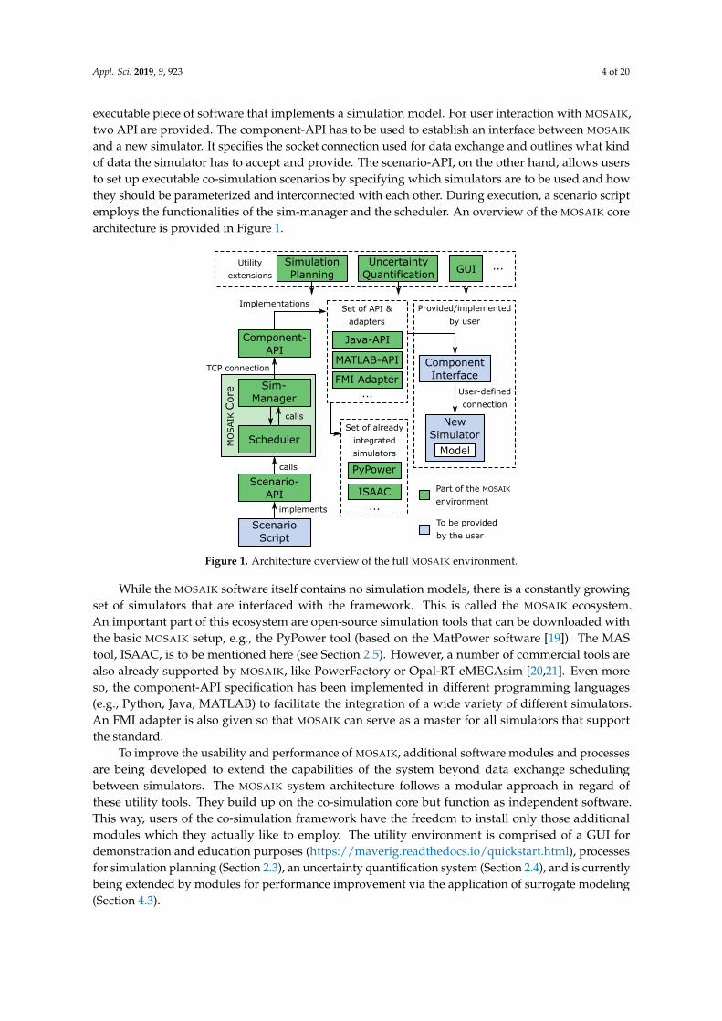
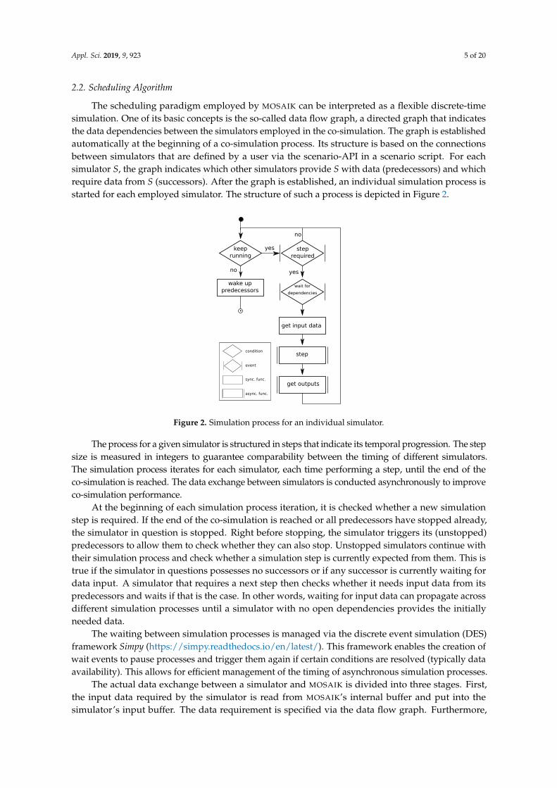
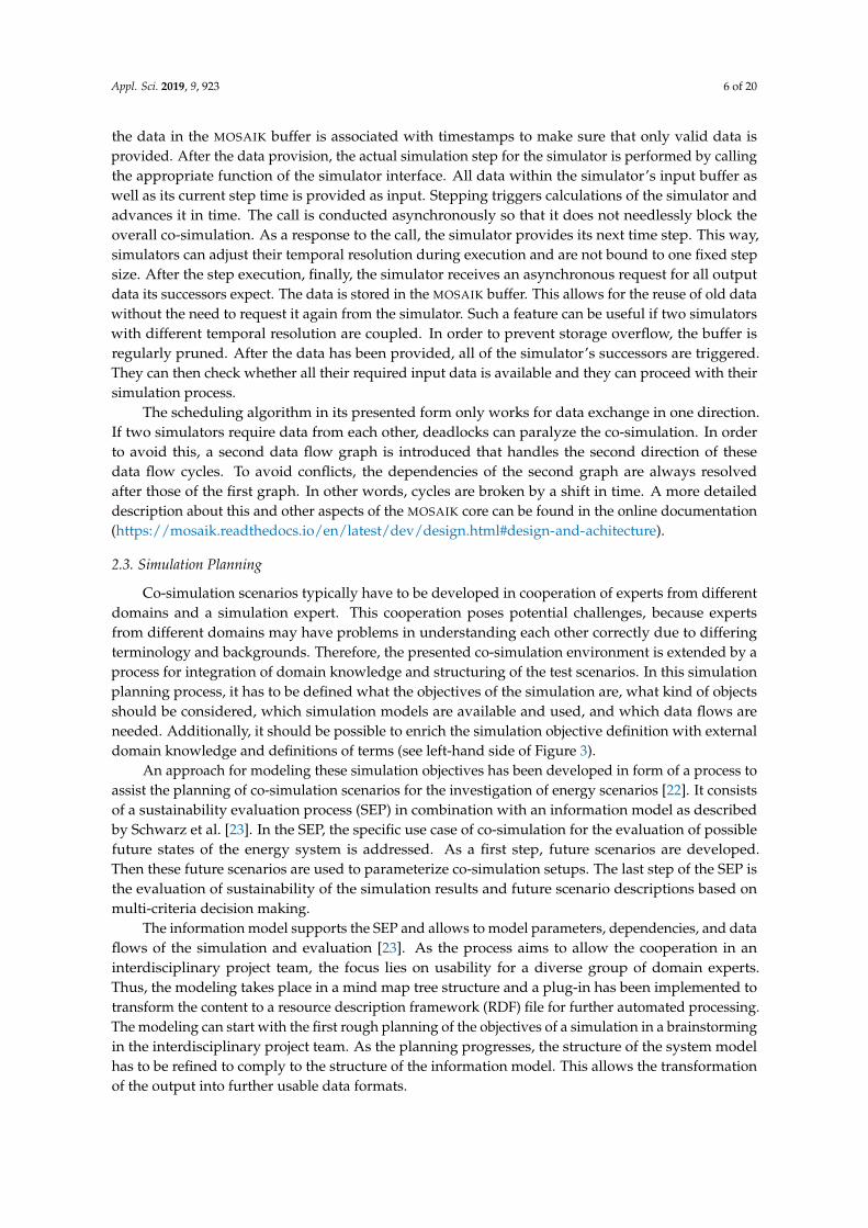
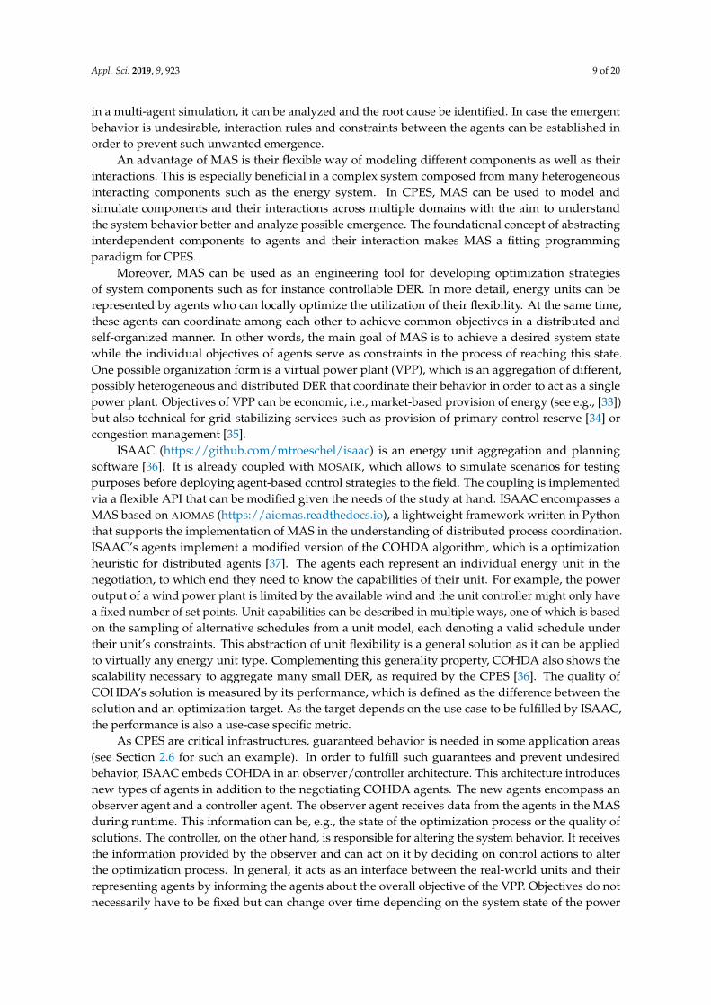
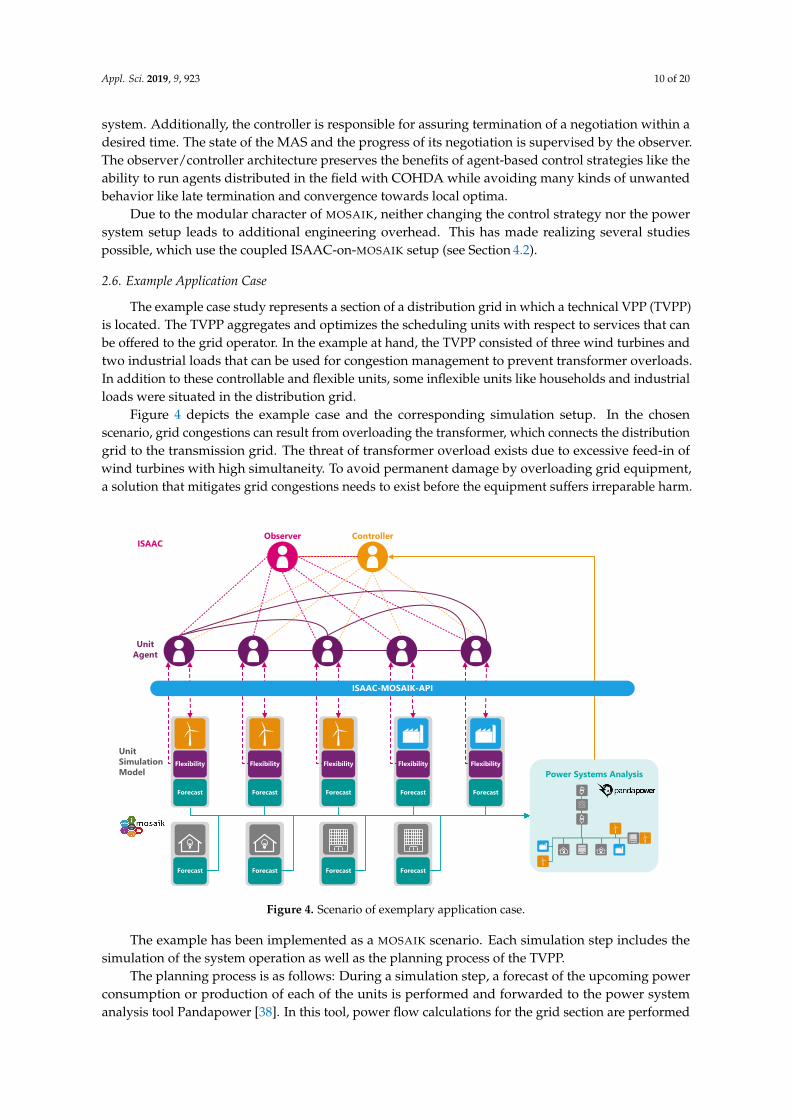
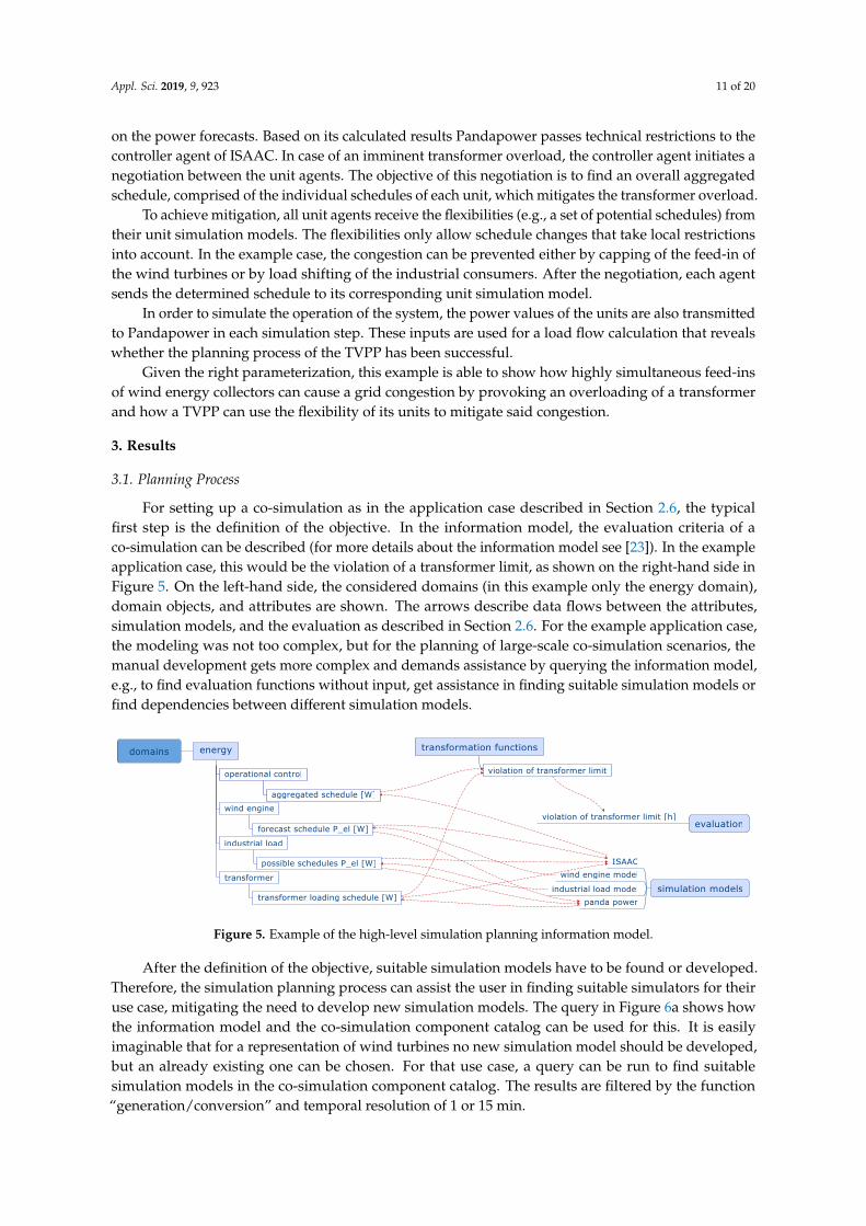
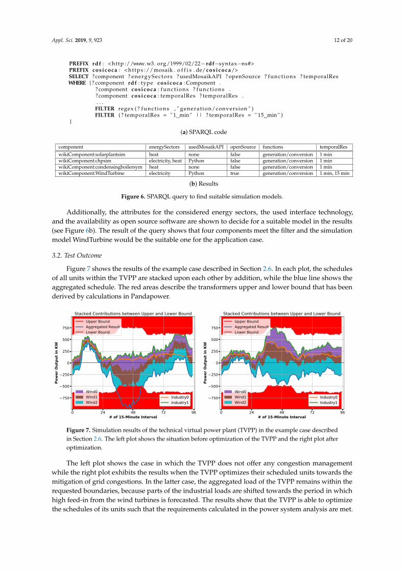
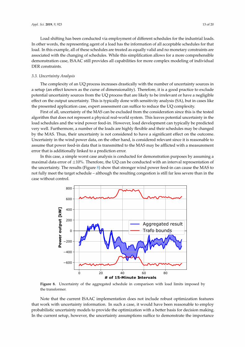