Embed Size (px)
Citation preview
© ISO 2014
Cutting tool data representation and exchange —Part 60: Reference dictionary for connection systemsReprésentation et échange des données relatives aux outils coupants —Partie 60: Dictionnaire de référence pour les systèmes de connexion
TECHNICAL SPECIFICATION
ISO/TS13399-60
Second edition2014-02-15
Reference numberISO/TS 13399-60:2014(E)
This preview is downloaded from www.sis.se. Buy the entire standard via https://www.sis.se/std-917041

ISO/TS 13399-60:2014(E)
ii © ISO 2014 – All rights reserved
COPYRIGHT PROTECTED DOCUMENT
© ISO 2014All rights reserved. Unless otherwise specified, no part of this publication may be reproduced or utilized otherwise in any form or by any means, electronic or mechanical, including photocopying, or posting on the internet or an intranet, without prior written permission. Permission can be requested from either ISO at the address below or ISO’s member body in the country of the requester.
ISO copyright officeCase postale 56 • CH-1211 Geneva 20Tel. + 41 22 749 01 11Fax + 41 22 749 09 47E-mail [email protected] www.iso.org
Published in Switzerland
This preview is downloaded from www.sis.se. Buy the entire standard via https://www.sis.se/std-917041
ISO/TS 13399-60:2014(E)
© ISO 2014 – All rights reserved iii
Contents Page
Foreword ........................................................................................................................................................................................................................................ivIntroduction ................................................................................................................................................................................................................................vi1 Scope ................................................................................................................................................................................................................................. 12 Normative references ...................................................................................................................................................................................... 23 Termsanddefinitions ..................................................................................................................................................................................... 24 Abbreviated terms .............................................................................................................................................................................................. 55 Representation of the ontology concepts as dictionary entries .......................................................................... 5
5.1 General ........................................................................................................................................................................................................... 55.2 connection interface feature ....................................................................................................................................................... 5
6 Properties for connection interface feature ............................................................................................................................ 86.1 General ........................................................................................................................................................................................................... 86.2 Definition of the structure of connection interface code .................................................................................... 96.3 Representation of connection interface code ............................................................................................................ 126.4 Representation of insert interface code ......................................................................................................................... 15
Annex A (normative) Information object registration ...................................................................................................................27Annex B (informative)Classificationtable..................................................................................................................................................28Annex C (informative)Classdefinitions .........................................................................................................................................................37Annex D (informative)Connectioninterfacefeaturepropertydefinitions ..............................................................87Annex E (informative) Illustrations of connection systems .......................................................................................................92Bibliography ......................................................................................................................................................................................................................... 138
This preview is downloaded from www.sis.se. Buy the entire standard via https://www.sis.se/std-917041
ISO/TS 13399-60:2014(E)
Foreword
ISO (the International Organization for Standardization) is a worldwide federation of national standards bodies (ISO member bodies). The work of preparing International Standards is normally carried out through ISO technical committees. Each member body interested in a subject for which a technical committee has been established has the right to be represented on that committee. International organizations, governmental and non-governmental, in liaison with ISO, also take part in the work. ISO collaborates closely with the International Electrotechnical Commission (IEC) on all matters of electrotechnical standardization.
The procedures used to develop this document and those intended for its further maintenance are described in the ISO/IEC Directives, Part 1. In particular the different approval criteria needed for the different types of ISO documents should be noted. This document was drafted in accordance with the editorial rules of the ISO/IEC Directives, Part 2 (see www.iso.org/directives).
Attention is drawn to the possibility that some of the elements of this document may be the subject of patent rights. ISO shall not be held responsible for identifying any or all such patent rights. Details of any patent rights identified during the development of the document will be in the Introduction and/or on the ISO list of patent declarations received (see www.iso.org/patents).
Any trade name used in this document is information given for the convenience of users and does not constitute an endorsement.
For an explanation on the meaning of ISO specific terms and expressions related to conformity assessment, as well as information about ISO’s adherence to the WTO principles in the Technical Barriers to Trade (TBT) see the following URL: Foreword - Supplementary information
The committee responsible for this document is ISO/TC 29, Small Tools.
This second edition cancels and replaces the first edition (ISO/TS 13399-60:2007), which has been technically revised. The following are the main changes:
— subclauses for connection interface features have been added in 5.2;
— Clause 6 has been revised.
ISO 13399 consists of the following parts, under the general title Cutting tool data representation and exchange:
— Part 1: Overview, fundamental principles and general information model
— Part 2: Reference dictionary for cutting items [Technical Specification]
— Part 3: Reference dictionary for tool items [Technical Specification]
— Part 4: Reference dictionary for adaptive items [Technical Specification]
— Part 5: Reference dictionary for assembly items [Technical Specification]
— Part 50: Reference dictionary for reference systems and common concepts [Technical Specification]
— Part 60: Reference dictionary for connection systems [Technical Specification]
— Part 100: Definitions, principles and methods for reference dictionaries [Technical Specification]
— Part 150: Usage guidelines [Technical Specification]
— Part 301:Concept for the design of 3D models based on properties according to ISO/TS 13399‑3: Modelling of thread‑cutting taps, thread‑forming taps and thread‑cutting dies [Technical Specification]
— Part 302:Concept for the design of 3D models based on properties according to ISO/TS 13399-3: Modelling of solid drills and countersinking tools [Technical Specification]
iv © ISO 2014 – All rights reserved
This preview is downloaded from www.sis.se. Buy the entire standard via https://www.sis.se/std-917041
ISO/TS 13399-60:2014(E)
The following parts are under preparation:
— Part 51: Designation system for customer solution cutting tools
— Part 80: Concept for the design of 3D models based on properties according to ISO 13399: Overview and principles [Technical Specification]
— Part 201: Concept for the design of 3D models based on properties according to ISO/TS 13399‑2: Modelling of regular inserts [Technical Specification]
— Part 202: Concept for the design of 3D models based on properties according to ISO/TS 13399‑2: Modelling of irregular inserts [Technical Specification]
— Part 203: Concept for the design of 3D models based on properties according to ISO/TS 13399‑2: Modelling of exchangeable inserts for drilling [Technical Specification]
— Part 204: Concept for the design of 3D models based on properties according to ISO/TS 13399‑2: Modelling of inserts for reaming [Technical Specification]
— Part 303: Concept for the design of 3D models based on properties according to ISO/TS 13399‑3: Modelling of end mills with non‑indexable cutting edges [Technical Specification]
— Part 304: Concept for the design of 3D models based on properties according to ISO/TS 13399‑3: Modelling of milling cutters with arbor hole and non‑indexable cutting edges [Technical Specification]
— Part 307: Concept for the design of 3D models based on properties according to ISO/TS 13399‑3: Modelling of end mills for indexable inserts [Technical Specification]
— Part 308: Concept for the design of 3D models based on properties according to ISO/TS 13399‑3: Modelling of milling cutter with arbor hole for indexable inserts [Technical Specification]
— Part 309: Concept for the design of 3D models based on properties according to ISO/TS 13399‑3: Tool holders for indexable inserts [Technical Specification]
— Part 311: Concept for the design of 3D models based on properties according to ISO/TS 13399‑3: Modelling of solid reamers [Technical Specification]
— Part 312: Concept for the design of 3D models based on properties according to ISO/TS 13399‑3: Modelling of reamers for indexable inserts [Technical Specification]
— Part 401: Concept for the design of 3D models based on properties according to ISO/TS 13399‑4: Modelling of converting, extending and reducing adaptive items [Technical Specification]
— Part 405: Concept for the design of 3D models based on properties according to ISO/TS 13399‑4: Modelling of collets [Technical Specification]
© ISO 2014 – All rights reserved v
This preview is downloaded from www.sis.se. Buy the entire standard via https://www.sis.se/std-917041
ISO/TS 13399-60:2014(E)
Introduction
This part of ISO 13399 defines the terms, properties, and definitions for connection systems of cutting tools with defined cutting edges. The purpose of this part of ISO 13399 is to provide a reference dictionary to support the use of the general information model in ISO 13399-1.
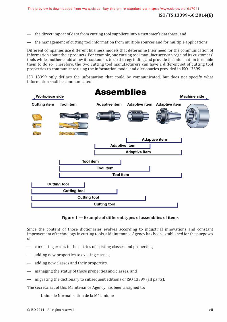
A cutting tool with defined cutting edges is used on a machine to remove material from a workpiece by a shearing action at the cutting edges of the tool. Cutting tool data that can be described by ISO 13399 (all parts) include, but are not limited to, everything between the workpiece and the machine tool. Information about inserts (e.g. regular and irregular shaped replaceable cutting items), solid tools (e.g. solid drill and endmill), assembled tools (e.g. boring bars, indexable drills, and indexable milling cutters), adaptors (e.g. milling arbor and drilling chuck), components (e.g. shims, screws, and clamps), and their relationships can be represented by ISO 13399 (all parts). Possible assemblies of the components of a cutting tool are illustrated in Figure 1.
The objective of ISO 13399 (all parts) is to provide the means to represent the information that describes cutting tools in a computer-sensible form that is independent from any computer system. The representation will facilitate the processing and exchange of cutting tool data within and between different software systems and computer platforms and support the application of this data in manufacturing planning, cutting operations, and the supply of tools. The nature of this description makes it suitable not only for neutral file exchange, but also as a basis for implementing and sharing product databases and for archiving. The methods used for these representations are those developed by ISO/TC 184/SC 4 for the representation of product data by using standardized information models and reference dictionaries.
An information model is a formal specification of types, ideas, facts, and processes which together describe a portion of interests of the real world and which provides an explicit set of interpretation rules. Information is knowledge of ideas, facts, and/or processes. Data are symbols or functions that represent information for processing purposes. Data are interpreted to extract information by using rules for how that should be done and a dictionary to define the terms that identify the data items. Everyone in a communication process is expected to use the same information model, the same set of explicit rules, and the same dictionary in order to avoid misunderstanding. If an information model and its dictionary are written in a computer-sensible language, then there is the additional benefit that they can be computer processable.
An engineering information model is therefore a specification for data that establishes the meaning of that data in a particular engineering context. A model has to be developed by formal methods to ensure that it meets the needs of the situation that it represents. An engineering information model defines the information objects that represent the concepts in an engineering application, the attributes of the objects, their relationships, and the constraints that add further meaning. An information model is an abstract concept that can be used repeatedly for any example of the real-world situation that it represents. An instance of the model is created when it is populated with the data items and their values that are applicable to a particular example of that situation.
This part of ISO 13399 uses the following International Standards developed by ISO/TC 184/SC 4:
— the EXPRESS language defined in ISO 10303-11 for defining the information model in ISO 13399-1;
— the file format for data exchange derived from the model and defined in ISO 10303-21;
— the data dictionary defined in the ISO 13584 series.
The ISO 13399 series is intended for use by, among others, tool producers and vendors, manufacturers, and developers of manufacturing software. ISO 13399 provides a common structure for exchanging data about cutting tools with defined cutting edges. ISO 13399 is intended to provide for, or improve, several manufacturing activities, including
— the integration and sharing of data for cutting tools and assemblies between different stages for the manufacturing cycle and between different software applications,
vi © ISO 2014 – All rights reserved
This preview is downloaded from www.sis.se. Buy the entire standard via https://www.sis.se/std-917041
ISO/TS 13399-60:2014(E)
— the direct import of data from cutting tool suppliers into a customer’s database, and
— the management of cutting tool information from multiple sources and for multiple applications.
Different companies use different business models that determine their need for the communication of information about their products. For example, one cutting tool manufacturer can regrind its customers’ tools while another could allow its customers to do the regrinding and provide the information to enable them to do so. Therefore, the two cutting tool manufacturers can have a different set of cutting tool properties to communicate using the information model and dictionaries provided in ISO 13399.
ISO 13399 only defines the information that could be communicated, but does not specify what information shall be communicated.
Figure 1 — Example of different types of assemblies of items
Since the content of those dictionaries evolves according to industrial innovations and constant improvement of technology in cutting tools, a Maintenance Agency has been established for the purposes of
— correcting errors in the entries of existing classes and properties,
— adding new properties to existing classes,
— adding new classes and their properties,
— managing the status of those properties and classes, and
— migrating the dictionary to subsequent editions of ISO 13399 (all parts).
The secretariat of this Maintenance Agency has been assigned to:
Union de Normalisation de la Mécanique
© ISO 2014 – All rights reserved vii
This preview is downloaded from www.sis.se. Buy the entire standard via https://www.sis.se/std-917041
ISO/TS 13399-60:2014(E)
F-92038 Paris La Défense CEDEX
France
by the ISO Technical Management Board.
The website of the Maintenance Agency is available at: http://www.unm.fr/main/core.php?pag_id=135
The reference dictionaries are available in the form of EXPRESS files on the website of the Maintenance Agency. These files are considered complementary to this part of ISO 13399; they can be freely downloaded and used for cutting tool data representation and exchange.
The following permission notice and disclaimer shall be included in all copies of this EXPRESS schema (“the Schema”), and derivations of the Schema:
© ISO 2014 – All rights reserved
Permission is hereby granted, free of charge in perpetuity, to any person obtaining a copy of the Schema, to use, copy, modify, merge and distribute free of charge, copies of the Schema for the purposes of developing, implementing, installing and using software based on the Schema, and to permit persons to whom the Schema is furnished to do so, subject to the following conditions:
THE SCHEMA IS PROVIDED “AS IS”, WITHOUT WARRANTY OF ANY KIND, EXPRESSED OR IMPLIED, INCLUDING, BUT NOT LIMITED TO, THE WARRANTIES OF MERCHANTABILITY, FITNESS FOR A PARTICULAR PURPOSE AND NON-INFRINGEMENT. IN NO EVENT SHALL ISO, OR ANY OTHER LICENSOR THAT GRANTS THE RIGHT UNDER THE ABOVE PERMISSION TO USE THE SCHEMA, BE LIABLE FOR ANY CLAIM, DAMAGES OR OTHER LIABILITY, WHETHER IN AN ACTION OF CONTRACT, TORT OR OTHERWISE, ARISING FROM, OUT OF OR IN CONNECTION WITH THE SCHEMA OR THE USE OR OTHER DEALINGS IN THE SCHEMA.
In addition, any modified copy of the Schema shall include the following notice:
THIS SCHEMA HAS BEEN MODIFIED FROM THE SCHEMA DEFINED IN ISO 13399, AND SHOULD
NOT BE INTERPRETED AS COMPLYING WITH THAT INTERNATIONAL STANDARD.
viii © ISO 2014 – All rights reserved
This preview is downloaded from www.sis.se. Buy the entire standard via https://www.sis.se/std-917041
TECHNICAL SPECIFICATION ISO/TS 13399-60:2014(E)
Cutting tool data representation and exchange —
Part 60: Reference dictionary for connection systems
1 Scope
This part of ISO 13399 specifies a reference dictionary for connection systems for cutting tools, together with their descriptive properties and domains of values.
This part of ISO 13399 specifies a reference dictionary and the structure of interface codes containing:
— definitions and identifications of the classes of connection systems, with an associated classification scheme;
— definitions and identifications of the data element types that represent the properties of connection systems;
— definitions and identifications of domains of values for describing the above data element types;
— definitions and structure of the value entry of the properties of interface codes that are already defined in this International Standard;
— rules for the structure of these properties to be able to communicate between systems.
Each class, property, or domain of values of this application domain constitutes an entry of the reference dictionary defined in this part of ISO 13399. It is associated with a computer-sensible and human-readable definition and with a computer-sensible identification. Identification of a dictionary entry allows unambiguous reference to it from any application that implements the information model defined in ISO 13399-1.
Definitions and identifications of dictionary entries are defined by means of standard data that consist of instances of the EXPRESS entity data types defined in the common dictionary schema, resulting from a joint effort between ISO/TC 184/SC 4 and IEC SC3D, and in its extensions defined in ISO 13584-24 and ISO 13584-25.
The following are within the scope of this part of ISO 13399:
— standard data that represent the various classes of connection systems for cutting tools;
— standard data that represent the various properties of connection systems for cutting tools;
— standard data that represent domains of values used for properties of connection systems for cutting tools;
— one implementation method by which the standard data defined in this part of ISO 13399 can be exchanged.
NOTE 1 The implementation method by which the standard data defined in this part of ISO 13399 can be exchanged is specified in ISO 10303-21.
The following are outside the scope of this part of ISO 13399:
— specialized or expert knowledge on the design and use of cutting tools;
— rules to determine what information should be communicated;
© ISO 2014 – All rights reserved 1
This preview is downloaded from www.sis.se. Buy the entire standard via https://www.sis.se/std-917041
ISO/TS 13399-60:2014(E)
— applications where these standard data can be stored or referenced;
— implementation methods other than the one defined in this part of ISO 13399 by which the standard data can be exchanged and referenced;
— information model for cutting tools;
— definitions of classes and properties for cutting items;
— definitions of classes and properties for tool items;
— definitions of classes and properties for assembly items;
— definitions of classes and properties for reference systems and common concepts.
NOTE 2 The information model for cutting tools is defined in ISO 13399-1.
NOTE 3 The definitions of classes and properties for cutting items, tool items, adaptive items, and assembly items are provided in ISO/TS 13399-2, ISO/TS 13399-3, ISO/TS 13399-4, and ISO/TS 13399-5, respectively.
NOTE 4 The definitions of classes and properties for reference systems and common concepts of general application are defined in ISO/TS 13399-50.
2 Normative references
The following documents, in whole or in part, are normatively referenced in this document and are indispensable for its application. For dated references, only the edition cited applies. For undated references, the latest edition of the referenced document (including any amendments) applies.
ISO 1832:2012, Indexable inserts for cutting tools — Designation
ISO 13399-1:2006, Cutting tool data representation and exchange — Part 1: Overview, fundamental principles and general information model
ISO/TS 13399-100, Cutting tool data representation and exchange — Part 100: Definitions, principles and methods for reference dictionaries
ISO 13584-1:2001, Industrial automation systems and integration — Parts library — Part 1: Overview and fundamental principles
3 Termsanddefinitions
For the purposes of this document, the terms and definitions given in ISO/TS 13399-100 (structure and contents of the dictionary) and the following apply.
NOTE The main collection of the terms and their definitions that relate to adaptive items and their properties is provided in Annexes B to D.
3.1applicable propertyproperty that is defined for some family of items and that shall apply to any member of this family
[SOURCE: ISO 13584-24:2003]
3.2basic semantic unitentity that provides an absolute and universally unique identification of a certain object of the application domain that is represented as a dictionary element
[SOURCE: ISO 13584-42:2010, 3.4]
2 © ISO 2014 – All rights reserved
This preview is downloaded from www.sis.se. Buy the entire standard via https://www.sis.se/std-917041
ISO/TS 13399-60:2014(E)
3.3chipmaterial removed from a workpiece by a cutting process
[SOURCE: ISO/TS 13399-2:2014, 3.3]
3.4cutting tooldevice or assembly of items for removing material from a workpiece through a shearing action at the defined cutting edge or edges of the device
[SOURCE: ISO 13399-1:2006, 3.1]
Note 1 to entry: A cutting tool could be the assembly of one or more adaptive items, a tool item, and several cutting items on a tool item. See Figure 1.
3.5datarepresentation of information in a formal manner suitable for communication, interpretation, or processing by human beings or computers
[SOURCE: ISO 10303-1:1994, 3.2.14]
3.6data element typeunit of data for which the identification, description, and value representation have been specified
[SOURCE: ISO 13584-42:2010, 3.13]
3.7data exchangestoring, accessing, transferring, and archiving of data
[SOURCE: ISO 10303-1:1994, 3.2.15]
3.8data typedomain of values
[SOURCE: ISO 10303-11:2004, 3.3.5]
3.9dictionarytable consisting of a series of entries with one meaning corresponding to each entry in the dictionary and one dictionary entry identifying a single meaning
[SOURCE: ISO 13584-511:2006, 3.1.9]
Note 1 to entry: In the ISO 13399 series, a dictionary is a formal and computer-sensible representation of an ontology.
3.10entityclass of information defined by its attributes which establishes a domain of values defined by common attributes and constraints
3.11entity data typerepresentation of an entity
© ISO 2014 – All rights reserved 3
This preview is downloaded from www.sis.se. Buy the entire standard via https://www.sis.se/std-917041
ISO/TS 13399-60:2014(E)
3.12entity instancenamed unit of data that represents a unit of information within the class defined by an entity
Note 1 to entry: An entity instance is a member of the domain established by an entity data type.
[SOURCE: ISO/TS 13399-2:2014, 3.12]
3.13family of productsset of products represented by the same characterization class
[SOURCE: ISO 13584-42:2010, 3.16]
3.15implementation methodmeans for computers to process or exchange data
3.16informationfacts, concepts, or instructions
[SOURCE: ISO 10303-1:1994, 3.2.20]
3.17information modelformal model of a bounded set of facts, concepts, or instructions to meet a specific requirement
[SOURCE: ISO 10303-1:1994, 3.2.21]
3.18machine sideidentification of a direction pointing towards the machine
3.19machined surfacesurface produced by the action of a cutting tool
[SOURCE: ISO 3002-1:1982, 3.1.2]
3.20ontologyexplicit and consensual specification of concepts of an application domain independent of any use of these concepts
[SOURCE: ISO 13584-511:2006, 3.1.20]
Note 1 to entry: In the ISO 13399 series, a dictionary is the formal and computer sensible representation of an ontology.
3.21propertydefined parameter suitable for the description and differentiation of products
[SOURCE: ISO 13584-42:2010, 3.37]
3.22simple family of itemsset of items in which each item can be described by the same group of properties
[SOURCE: ISO 13584-42:1998, 3.1.3]
4 © ISO 2014 – All rights reserved
This preview is downloaded from www.sis.se. Buy the entire standard via https://www.sis.se/std-917041
ISO/TS 13399-60:2014(E)
3.23visible propertyproperty that has a definition meaningful in the scope of a given characterization class, but that does not necessarily apply to the various products belonging to this class
[SOURCE: ISO 13584-42:2010, 3.46]
3.24workpieceobject on which a cutting action is performed
[SOURCE: ISO/TS 13399-2:2014; 3.24]
3.25workpiece sideidentification of a direction pointing towards the workpiece
4 Abbreviated terms
For the purposes of this document, the following abbreviated terms apply.
BSU basic semantic unit
DET data element type
5 Representation of the ontology concepts as dictionary entries
5.1 General
In 5.2, a concept in the ontology is identified by a name in lowercase characters. The name of a class that represents the concept in the dictionary is identified by bold, lowercase characters with multiple words linked by an underscore character.
EXAMPLE “connection interface feature” is the name of a concept in the ontology. connection interface feature is the identifier of the class in the dictionary that represents the concept.
Each entry in the dictionary, either a class or a property, is identified with a numerical code (BSU) that is generated at random when the dictionary is compiled. A BSU can be made unique by the addition of a code that is a reference to the supplier of the dictionary.
The structure of the classification is summarized in Annex B. The complete definitions of the classes in this part of ISO 13399 are provided in Annex C. The properties applicable to these classes are defined in Annex D.
5.2 connection interface feature
connection_interface_feature is a generic family of those parts of a tool item or assembly item that form a coupling to another tool item or assembly item or machine tool. Definitions and further sub-division of these classes can be found in Annex C.
connection_interface_feature has the following subclasses:1)
— ABS_System_Komet;
1) The identifications for some of these entities are derived from commercial trade names and company names that may be protected. Their use in this part of ISO 13399 is justified by their being in common use with no accepted generic alternatives. This information is given for the convenience of users of this part of ISO 13399 and does not constitute an endorsement by ISO of these products.
© ISO 2014 – All rights reserved 5
This preview is downloaded from www.sis.se. Buy the entire standard via https://www.sis.se/std-917041
ISO/TS 13399-60:2014(E)
— AIF_Adjustable_Interface_Dihart;
— AWN_Prisma_connection_Schwanog;
— BFA_drill_chuck_connection;
— BKA_boring_head_connection;
— BKC_boring_head_connection_Coromant;
— BKI_boring_head_connection_Iscar;
— BRP_Bridgeport_connection;
— BTS_Block_Tool_System_Coromant;
— BUF_boring_and_chamfer_system;
— CBC_Coromant_Bridge_Connection;
— CCB_Coromant_CoroBore;
— CCM_Coromant_Cap_Mounting;
— CCS_Coromant_Capto_system;
— CDB_Coromant_Duobore;
— CFB_Coromant_Fine_Boring;
— CKB_Kaiser_bore_connection;
— CKS_Kaiser_shank_connection;
— CMS_Coromant_Modular_Serrated_mounting;
— CUD_Coromant_U-drill_connection;
— FCM_Flexible_Coupling_Modular_system;
— FDA_milling_arbor_connection;
— FLC_flange_connection_Coromant;
— FLK_flange_connector_Kennametal;
— FTS_Flexible_Tooling_System_Kennametal;
— GMS_Graflex_Modular_System_SECO;
— GRL_Granlund_connection;
— HEE_HE-/HF-system_EMUGE;
— HFS_head_fitting_system_Mapal;
— HSK_hollow_taper_shank;
— HSZ_hollow_cylindrical_shank;
— HTS_deep_drilling_system;
— ICF_Iscar_clickfit_system;
— IMB_modular_connection_system_Iscar;
6 © ISO 2014 – All rights reserved
This preview is downloaded from www.sis.se. Buy the entire standard via https://www.sis.se/std-917041
ISO/TS 13399-60:2014(E)
— IMC_Iscar_metal_cutting_connection;
— KKG_stub_taper;
— KKH__ISO_cartridge_mounting;
— KMB_Kennametal_ModBore_system;
— KMC_Kennametal_cartridge_mounting;
— KMM_Kennametal_Micro_system;
— KMT_KM-UTS_system_Kennametal/Widia;
— KRS_Kennametal_Romicron_system;
— KVT_KV_system_Kennametal;
— MBS_Multi_Blade_System_Coromant;
— MCS_modular_cartridge_system_Kennametal;
— MEG_metric_taper;
— MKG_Morse_taper;
— MVS_modular_connection_system_Wohlhaupter;
— NCT_Novex-NC-Tools_Walter;
— PMC_prismatic_connection_Coromant;
— PMD_prismatic_connection_standard;
— PMI_prismatic_connection_Iscar;
— PMK_prismatic_connection_Kennametal;
— PMS_prismatic_connection_SECO;
— RFX_Rotaflex_system_Widia;
— SAI_screw_connection_Iscar;
— SAC_screw_connection_Coromant;
— SBA_SBA-system_Komet;
— SCA_SECO_cartridge_mounting;
— SCR_SECO_crownlock_connection;
— SKG_Steep_taper;
— SMM_SECO_minimaster;
— SMS_SECO_modular_serrated_connection;
— SPK_holding_arbor;
— SRT_SECO_R_shank;
— STH_automotive_shank;
— SWB_quick_change_connection;
© ISO 2014 – All rights reserved 7
This preview is downloaded from www.sis.se. Buy the entire standard via https://www.sis.se/std-917041
ISO/TS 13399-60:2014(E)
— SZB_collet_shortened_design_Biax;
— SZC_collet_connection_Coromant;
— SZD_collet_connection_standard;
— SZE_collet_connection_Erikson;
— SZP_collet_Eminent_–_Perman;
— SZR_collet_KSF_Roehm;
— SZS_collet_Steinel_Bohrmaster;
— URM_Urma_connection;
— UTS_UTS_Widia;
— VAS_Variant_System_Coromant;
— VKT_rectangular_connection;
— VLS_Varilock_System_Coromant;
— ZYL_cylindrical_shank_connection;
— ZYV_VDI_shank.
6 Properties for connection interface feature
6.1 General
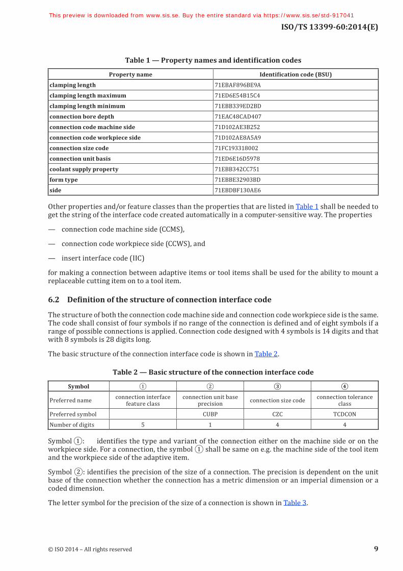
The properties that are applicable to the items defined in Clause 5 are defined in Annex D, where the association of a property with a class is also specified. In the compilation of the dictionary, all properties are visible properties at the root class of the dictionary and are made applicable properties at the class level where they apply. The names of properties that can be applicable to connection interface feature, with their identification codes (BSU), are shown in Table 1. The order of the names in Table 1 should be read in rows from left to right.
NOTE 1 The value domains for properties are specified in ISO/TS 13399-100.
NOTE 2 The BSU can be made unique by the addition of the code for the supplier of the dictionary as a prefix to the identification code.
EXAMPLE The unique BSU for clamping length would be: 0112/1///13399__2-71EBAF896BE9A for version two of the dictionary.
8 © ISO 2014 – All rights reserved
This preview is downloaded from www.sis.se. Buy the entire standard via https://www.sis.se/std-917041
ISO/TS 13399-60:2014(E)
Table1—Propertynamesandidentificationcodes
Property name Identificationcode(BSU)
clamping length 71EBAF896BE9A
clamping length maximum 71ED6E54B15C4
clamping length minimum 71EBB339ED2BD
connection bore depth 71EAC48CAD407
connection code machine side 71D102AE3B252
connection code workpiece side 71D102AE8A5A9
connection size code 71FC193318002
connection unit basis 71ED6E16D5978
coolant supply property 71EBB342CC751
form type 71EBBE32903BD
side 71EBDBF130AE6
Other properties and/or feature classes than the properties that are listed in Table 1 shall be needed to get the string of the interface code created automatically in a computer-sensitive way. The properties
— connection code machine side (CCMS),
— connection code workpiece side (CCWS), and
— insert interface code (IIC)
for making a connection between adaptive items or tool items shall be used for the ability to mount a replaceable cutting item on to a tool item.
6.2 Definitionofthestructureofconnectioninterfacecode
The structure of both the connection code machine side and connection code workpiece side is the same. The code shall consist of four symbols if no range of the connection is defined and of eight symbols if a range of possible connections is applied. Connection code designed with 4 symbols is 14 digits and that with 8 symbols is 28 digits long.
The basic structure of the connection interface code is shown in Table 2.
Table 2 — Basic structure of the connection interface code
Symbol ① ② ③ ④
Preferred name connection interface feature class
connection unit base precision connection size code connection tolerance
class
Preferred symbol CUBP CZC TCDCON
Number of digits 5 1 4 4
Symbol ①: identifies the type and variant of the connection either on the machine side or on the workpiece side. For a connection, the symbol ① shall be same on e.g. the machine side of the tool item and the workpiece side of the adaptive item.
Symbol ②: identifies the precision of the size of a connection. The precision is dependent on the unit base of the connection whether the connection has a metric dimension or an imperial dimension or a coded dimension.
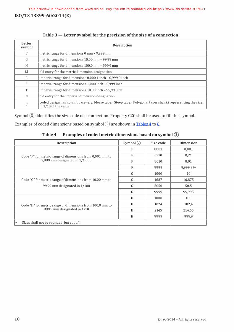
The letter symbol for the precision of the size of a connection is shown in Table 3.
© ISO 2014 – All rights reserved 9
This preview is downloaded from www.sis.se. Buy the entire standard via https://www.sis.se/std-917041
ISO/TS 13399-60:2014(E)
Table 3 — Letter symbol for the precision of the size of a connection
Letter symbol Description
F metric range for dimensions 0 mm – 9,999 mm
G metric range for dimensions 10,00 mm – 99,99 mm
H metric range for dimensions 100,0 mm – 999,9 mm
M old entry for the metric dimension designation
R imperial range for dimensions 0,000 1 inch – 0,999 9 inch
S imperial range for dimensions 1,000 inch – 9,999 inch
T imperial range for dimensions 10,00 inch – 99,99 inch
N old entry for the imperial dimension designation
C coded design has no unit base (e. g. Morse taper, Steep taper, Polygonal taper shank) representing the size in 1/10 of the value
Symbol ③: identifies the size code of a connection. Property CZC shall be used to fill this symbol.
Examples of coded dimensions based on symbol ② are shown in Tables 4 to 6.
Table4—Examplesofcodedmetricdimensionsbasedonsymbol②
Description Symbol② Size code Dimension
Code “F” for metric range of dimensions from 0,001 mm to 9,999 mm designated in 1/1 000
F 0001 0,001
F 0210 0,21
F 8010 8,01
F 9999 9,999 87a
Code “G” for metric range of dimensions from 10,00 mm to
99,99 mm designated in 1/100
G 1000 10
G 1687 16,875
G 5050 50,5
G 9999 99,995
Code “H” for metric range of dimensions from 100,0 mm to 999,9 mm designated in 1/10
H 1000 100
H 1024 102,4
H 2145 214,55
H 9999 999,9a Sizes shall not be rounded, but cut off.
10 © ISO 2014 – All rights reserved
This preview is downloaded from www.sis.se. Buy the entire standard via https://www.sis.se/std-917041
ISO/TS 13399-60:2014(E)
Table5—Examplesofcodedimperialdimensionsbasedonsymbol②
Description Symbol② Size code Dimension
Code “R” for imperial range of dimensions from 0,000 1 inch to 0,999 9 inch designated in 1/10 000
R 0393 0,039 3
R 1875 0,187 5 (3/16)
R 2500 0,25 (1/4)
R 9999 0,999 9
Code “S” for imperial range of dimensions from 1,000 inch to 9,999 inch designated in 1/1 000
S 1000 1
S 1015 1,015 625a (1 1/64)
S 2500 2,5
S 9999 9,999
Code “T” for imperial range of dimensions from 10,00 inch to 99,99 inch designated in 1/100
T 1025 10,25
T 2525 25,25
T 5600 56
T 9999 99,99a Sizes shall not be rounded, but cut off.
Table6—Examplesofcodednon-unitdimensionsbasedonsymbol②“C”
Size code
Symbol①connectioninterfacefeatureclass
CCS01
(ISO 26623)
HSK01
(ISO 12164-1)
KMT01
(ISO 26622)
MKG
(ISO 296)
SKG10
(ISO 7388-1)
0000 0
0010 1
0020 2
0030 3
0040 4
0050 5
0060 6
0250 25
0300 30
0320 3 32 32
0400 4 40 40 40
0450 45
0500 5 50 50 50
0600 60
0630 6 63 63
0650 65
0700 70
0800 8 80 80
1000 10 100 100
1250 125
1600 160
Symbol ④: identifies the ISO tolerance class of a connection. The first two digits identify the position and the second two digits identify the grade of the tolerance zone; all four digits shall represent the ISO tolerance class. If the position is represented with only one letter, the second digit shall be filled with
© ISO 2014 – All rights reserved 11
This preview is downloaded from www.sis.se. Buy the entire standard via https://www.sis.se/std-917041

![Cutting sequences in Veech surfaces - arXivarxiv.org/pdf/1507.02469.pdf1 Cutting sequences for the hexagon 1.1 Maindefinitions Following[SU11]wecanprovidethesameconstructionforthehexagon](https://img.pdfslide.fr/doc/110x75/5f9765266be8da19ff51ed07/cutting-sequences-in-veech-surfaces-1-cutting-sequences-for-the-hexagon-11-maindeinitions.jpg)