Embed Size (px)
Citation preview
Received: September 28, 2019. Revised: November 22, 2019. 259
International Journal of Intelligent Engineering and Systems, Vol.13, No.1, 2020 DOI: 10.22266/ijies2020.0229.24
Decentralized Control of Cooperative Robotics System Using Neural Networks
for the Purpose of an Object Balancing Flat Plate Tasks
Nattapon Jaisumroum1 Pholchai Chotiprayanakul1 Wipoo Sriseubsai1*
1Faculty of Engineering, King Mongkut’s Institute of Technology Ladkrabang, Thailand
* Corresponding author’s Email: [email protected]
Abstract: In this article, the manipulation to handle the object on a plate using neural networks, design of 1-DOF
robot arm under cooperative control, will be explained. The robot’s system specifies the object position and velocity,
an assignment oriented components for cooperative control. The novelty of this experiment is that under the
decentralized control, the robot estimates the position and speed of the object for control end-effector of robot arm
using the camera to track position and speed of the object according to training and assigned collaborative tasks
which differ from other experiments that use sensors. The experiment includes three robot manipulators which were
capable balancing the objects on flat plate with dataset to training and control servo motor assigned to the
corresponding position and the end-effector in decentralized to control robotics. Overall, neural network method can
be a training scheme using a cooperative robotics in a decentralized control.
Keywords: Decentralized control, Neural networks, Cooperative robotics, Dynamic object manipulation.
1. Introduction
The robotics system can be contained in a single
and multiple manipulators, and the complicated task
accepting multi-robot has exceptional
accommodation than a single robot to essentially
handle and assembly heavy materials. A number of
researchers have studied cooperative control in
multiple robots for various tasks. Learning object
handling practice with robotics is a challenging
obstacle since the trajectories to propose appropriate
handling practice perhaps varied with respect to
different situations. Even when it comes to handling
the duplicated objects, the evolution of motor in
time would be a little different provided to the
robotics, and the object movement is located in
workspace. This paper shows that an artificial neural
network method is adequate for the training on the
practice for robotics collaborative balancing of the
object. There are many articles of the previous
research on the robotic learning for object handling
[1]. The improvements on controlling a DC servo
motors are obvious positioned and speed in flexible
control. DC servo motors are generally used for a
collection in industry, robotic systems. The control
specifies the motion of the object being grasped and
handling the object by the robot’s arm, the latter of
which has no effect on the object movement. The
coordinates depend on the impedance control [2, 3]
and hybrid control in force or position [4, 5] and the
parameter of manipulator where the objects are
placed. This is the recognition on the accuracy to
determine the parameter between manipulator and
the object position. In order to control multi-robot
dynamic parameters uncertainty task, neural
networks method [6], learning and training methods
[7] and fuzzy sliding mode method [8, 9] in control
are suggested. These techniques involve the
measurement of times and forces at an end-effector
and the adoption of a centralized controller. The
sensor is comparatively costly and readily damaged.
Centralized control methods are implementation in
previous researches of the robotics collaboration.
Decentralized control methods [10, 11] in
manipulator is governed independently with the
controller, are therefore desirable methods due to
Received: September 28, 2019. Revised: November 22, 2019. 260
International Journal of Intelligent Engineering and Systems, Vol.13, No.1, 2020 DOI: 10.22266/ijies2020.0229.24
their simple model. The neural network control is a
very successful to solve in nonlinear problems. Thus,
neural networks method develops to be an
influential tool for learning in linear and extremely
nonlinear problems on dynamic systems. The neural
network method, rapid variation and elemental
approximation proficiency, have appeal to
considerable in a researches of robotic engineering,
identification and control. In the literature, the use of
neural network architecture to regulate complicated
and uncertainty in systems has become a subject of
significant considerable [12-14]. Most of the
research in this field has created and developed the
new techniques of object manipulation in a decade.
Non-prehensile dynamic of object in manipulation
approaches in fields of robotic these new methods.
The manipulation of object implies the robotics with
no grasp, i.e. the robotic can easily balance object,
even with no other robotics during the cooperative
assignment [15]. However, these decentralized
controllers are adaptive and do not require a sensor
to evaluate the relationships between the robotics
interaction and the target object. This article
proposes a decentralization in neural network
control technique without a sensor for multi-robot
can be detect the object using web camera, robotic
eyes to collaborate balancing the object with other
robot interactions. In this study, the parameters of
the robotic arms and the object movement are
approximated and the motions of robotic
cooperating by referring to the neural network
model will be explained. For example, the object
handling task, the lessons learned by the robots on
choosing between the predefined behaviors
aboriginal, approaching releasing and carrying an
object for particular step. However, this method can
be applied to a dynamic object handling behavior
[16]. In this study, decentralized control
implementing neural network method in cooperative
tasks, rather than using sensors the same as other
experiments, for balancing the object position,
velocity and manipulations utilizing a robot arm are
experimented.
2. Methodology
2.1 Dynamics system modeling
The time pivot is included to the position in
coordinate and robotics are done in dynamics of
object handling system and in rotating processes in
specific. The dynamic of object handling methods in
manipulation techniques is rolling on flat-plate
where balancing with a robot arm, robotics
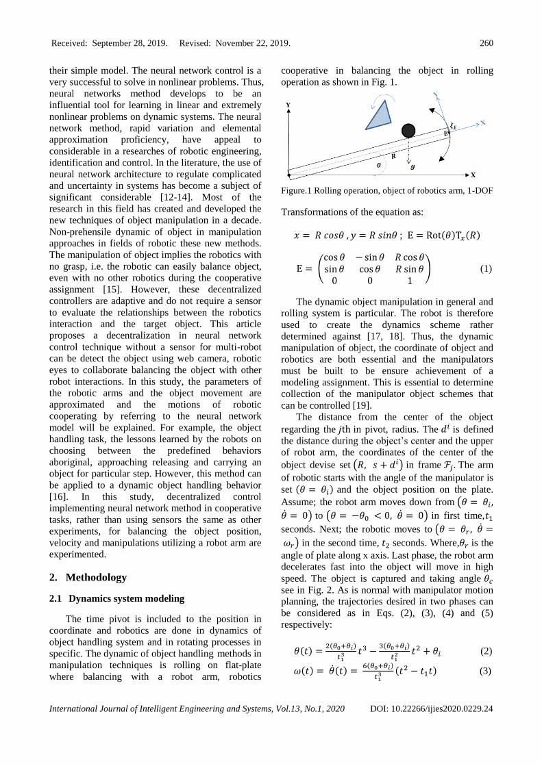
cooperative in balancing the object in rolling
operation as shown in Fig. 1.
Figure.1
Rolling operation, object of robotics arm, 1-DOF
Transformations of the equation as:
𝑥 = 𝑅 𝑐𝑜𝑠𝜃 , 𝑦 = 𝑅 𝑠𝑖𝑛𝜃 ; E = Rot(𝜃)T𝑥(𝑅)
E = (cos 𝜃 − sin 𝜃 𝑅 cos 𝜃sin 𝜃 cos 𝜃 𝑅 sin 𝜃
0 0 1) (1)
The dynamic object manipulation in general and
rolling system is particular. The robot is therefore
used to create the dynamics scheme rather
determined against [17, 18]. Thus, the dynamic
manipulation of object, the coordinate of object and
robotics are both essential and the manipulators
must be built to be ensure achievement of a
modeling assignment. This is essential to determine
collection of the manipulator object schemes that
can be controlled [19].
The distance from the center of the object
regarding the 𝑗th in pivot, radius. The 𝑑𝑖 is defined
the distance during the object’s center and the upper
of robot arm, the coordinates of the center of the
object devise set (𝑅, 𝑠 + 𝑑𝑖) in frame ℱ𝑗 . The arm
of robotic starts with the angle of the manipulator is
set (𝜃 = 𝜃𝑖) and the object position on the plate.
Assume; the robot arm moves down from (𝜃 = 𝜃𝑖,
�̇� = 0) to (𝜃 = −𝜃0 < 0, �̇� = 0) in first time,𝑡1
seconds. Next; the robotic moves to (𝜃 = 𝜃𝑟, �̇� =
𝜔𝑟) in the second time, 𝑡2 seconds. Where,𝜃𝑟 is the
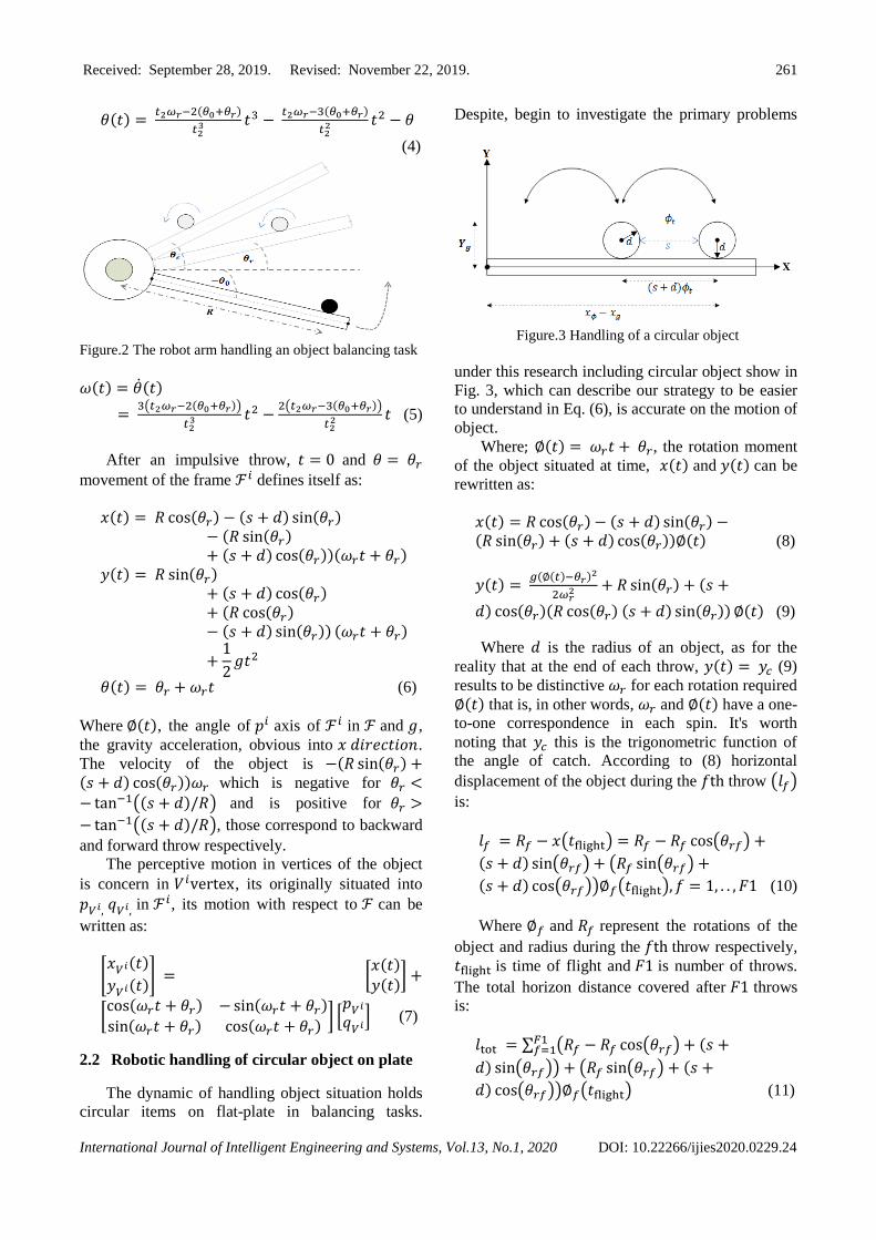
angle of plate along x axis. Last phase, the robot arm
decelerates fast into the object will move in high
speed. The object is captured and taking angle 𝜃𝑐
see in Fig. 2. As is normal with manipulator motion
planning, the trajectories desired in two phases can
be considered as in Eqs. (2), (3), (4) and (5)
respectively:
𝜃(𝑡) =2(𝜃0+𝜃𝑖)
𝑡13 𝑡3 −
3(𝜃0+𝜃𝑖)
𝑡12 𝑡2 + 𝜃𝑖 (2)
𝜔(𝑡) = �̇�(𝑡) = 6(𝜃0+𝜃𝑖)
𝑡13 (𝑡2 − 𝑡1𝑡) (3)
Received: September 28, 2019. Revised: November 22, 2019. 261
International Journal of Intelligent Engineering and Systems, Vol.13, No.1, 2020 DOI: 10.22266/ijies2020.0229.24
𝜃(𝑡) = 𝑡2𝜔𝑟−2(𝜃0+𝜃𝑟)
𝑡23 𝑡3 −
𝑡2𝜔𝑟−3(𝜃0+𝜃𝑟)
𝑡22 𝑡2 − 𝜃
(4)
Figure.2 The robot arm handling an object balancing task
𝜔(𝑡) = �̇�(𝑡)
= 3(𝑡2𝜔𝑟−2(𝜃0+𝜃𝑟))
𝑡23 𝑡2 −
2(𝑡2𝜔𝑟−3(𝜃0+𝜃𝑟))
𝑡22 𝑡 (5)
After an impulsive throw, 𝑡 = 0 and 𝜃 = 𝜃𝑟
movement of the frame ℱ𝑖 defines itself as:
𝑥(𝑡) = 𝑅 cos(𝜃𝑟) − (𝑠 + 𝑑) sin(𝜃𝑟)− (𝑅 sin(𝜃𝑟)+ (𝑠 + 𝑑) cos(𝜃𝑟))(𝜔𝑟𝑡 + 𝜃𝑟)
𝑦(𝑡) = 𝑅 sin(𝜃𝑟)+ (𝑠 + 𝑑) cos(𝜃𝑟)+ (𝑅 cos(𝜃𝑟)− (𝑠 + 𝑑) sin(𝜃𝑟)) (𝜔𝑟𝑡 + 𝜃𝑟)
+1
2𝑔𝑡2
𝜃(𝑡) = 𝜃𝑟 + 𝜔𝑟𝑡 (6)
Where ∅(𝑡), the angle of 𝑝𝑖 axis of ℱ𝑖 in ℱ and 𝑔,
the gravity acceleration, obvious into 𝑥 𝑑𝑖𝑟𝑒𝑐𝑡𝑖𝑜𝑛.
The velocity of the object is −(𝑅 sin(𝜃𝑟) +(𝑠 + 𝑑) cos(𝜃𝑟))𝜔𝑟 which is negative for 𝜃𝑟 <− tan−1((𝑠 + 𝑑)/𝑅) and is positive for 𝜃𝑟 >
− tan−1((𝑠 + 𝑑)/𝑅), those correspond to backward
and forward throw respectively.
The perceptive motion in vertices of the object
is concern in 𝑉𝑖vertex, its originally situated into
𝑝𝑉𝑖, 𝑞𝑉𝑖, in ℱ𝑖, its motion with respect to ℱ can be
written as:
[𝑥𝑉𝑖(𝑡)
𝑦𝑉𝑖(𝑡)] = [
𝑥(𝑡)
𝑦(𝑡)] +
[cos(𝜔𝑟𝑡 + 𝜃𝑟) − sin(𝜔𝑟𝑡 + 𝜃𝑟)
sin(𝜔𝑟𝑡 + 𝜃𝑟) cos(𝜔𝑟𝑡 + 𝜃𝑟)] [
𝑝𝑉𝑖
𝑞𝑉𝑖] (7)
2.2 Robotic handling of circular object on plate
The dynamic of handling object situation holds
circular items on flat-plate in balancing tasks.
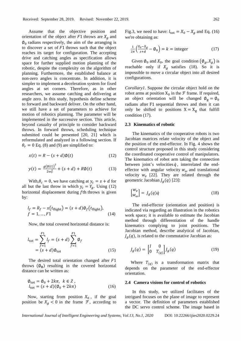
Despite, begin to investigate the primary problems
Figure.3 Handling of a circular object
under this research including circular object show in
Fig. 3, which can describe our strategy to be easier
to understand in Eq. (6), is accurate on the motion of
object.
Where; ∅(𝑡) = 𝜔𝑟𝑡 + 𝜃𝑟, the rotation moment
of the object situated at time, 𝑥(𝑡) and 𝑦(𝑡) can be
rewritten as:
𝑥(𝑡) = 𝑅 cos(𝜃𝑟) − (𝑠 + 𝑑) sin(𝜃𝑟) −(𝑅 sin(𝜃𝑟) + (𝑠 + 𝑑) cos(𝜃𝑟))∅(𝑡) (8)
𝑦(𝑡) = 𝑔(∅(𝑡)−𝜃𝑟)2
2𝜔𝑟2 + 𝑅 sin(𝜃𝑟) + (𝑠 +
𝑑) cos(𝜃𝑟)(𝑅 cos(𝜃𝑟) (𝑠 + 𝑑) sin(𝜃𝑟)) ∅(𝑡) (9)
Where 𝑑 is the radius of an object, as for the
reality that at the end of each throw, 𝑦(𝑡) = 𝑦𝑐 (9)
results to be distinctive 𝜔𝑟 for each rotation required
∅(𝑡) that is, in other words, 𝜔𝑟 and ∅(𝑡) have a one-
to-one correspondence in each spin. It's worth
noting that 𝑦𝑐 this is the trigonometric function of
the angle of catch. According to (8) horizontal
displacement of the object during the 𝑓th throw (𝑙𝑓)
is:
𝑙𝑓 = 𝑅𝑓 − 𝑥(𝑡flight) = 𝑅𝑓 − 𝑅𝑓 cos(𝜃𝑟𝑓) +
(𝑠 + 𝑑) sin(𝜃𝑟𝑓) + (𝑅𝑓 sin(𝜃𝑟𝑓) +
(𝑠 + 𝑑) cos(𝜃𝑟𝑓))∅𝑓(𝑡flight), 𝑓 = 1, . . , 𝐹1 (10)
Where ∅𝑓 and 𝑅𝑓 represent the rotations of the
object and radius during the 𝑓th throw respectively,
𝑡flight is time of flight and 𝐹1 is number of throws.
The total horizon distance covered after 𝐹1 throws
is:
𝑙tot = ∑ (𝑅𝑓 − 𝑅𝑓 cos(𝜃𝑟𝑓) + (𝑠 +𝐹1𝑓=1
𝑑) sin(𝜃𝑟𝑓)) + (𝑅𝑓 sin(𝜃𝑟𝑓) + (𝑠 +
𝑑) cos(𝜃𝑟𝑓))∅𝑓(𝑡flight) (11)
Received: September 28, 2019. Revised: November 22, 2019. 262
International Journal of Intelligent Engineering and Systems, Vol.13, No.1, 2020 DOI: 10.22266/ijies2020.0229.24
Assume that the objective position and
orientation of the object after 𝐹1 throws are 𝑋𝑔 and
∅0 radians respectively, the aim of the arranging is
to discover a set of 𝐹1 throws such that the object
reaches its target for configuration. The accepting
drive and catching angles as specification allows
space for further supplied motion planning of the
robotic, despite the complexity on the algorithm of
planning. Furthermore, the established balance at
non-zero angles is concentrate. In addition, it is
simpler to implement a deceleration system for fixed
angles at set corners. Therefore, as in other
researchers, we assume catching and delivering at
angle zero. In this study, hypothesis define scheme
to forward and backward deliver. On the other hand,
we still have a set of parameters to achieve for
motion of robotics planning. The parameter will be
implemented in the successive section. This article,
beyond casualty of principle to consider backward
throws. In forward throws, scheduling technique
submitted could be presented [20, 21] which is
reformulated and analyzed in a following section. If
𝜃𝑟 = 0 Eq. (8) and (9) are simplified to:
𝑥(𝑡) = 𝑅 − (𝑠 + 𝑑)∅(𝑡) (12)
𝑦(𝑡) = 𝑔(∅(𝑡))
2
2𝜔𝑟2 + (𝑠 + 𝑑) + 𝑅∅(𝑡) (13)
With,𝜃𝑐 = 0, we have catching at 𝑦𝑐 = 𝑠 + 𝑑 for
all but the last throw in which 𝑦𝑐 = 𝑌𝑔. Using (12)
horizontal displacement during 𝑓th throws is given
by:
𝑙𝑓 = 𝑅𝑓 − 𝑥(𝑡flight) = (𝑠 + 𝑑)∅𝑓(𝑡flight),
𝑓 = 1, … , 𝐹1 (14)
Now, the total covered horizontal distance is:
𝑙tot = ∑ 𝑙𝑓
𝐹1
𝑓=1
= (𝑠 + 𝑑) ∑ ∅𝑓
𝐹1
𝑓=1
= (𝑠 + 𝑑)∅tot (15)
The desired total orientation changed after 𝐹1
throws (∅𝟎) resulting in the covered horizontal
distance can be written as:
∅tot = ∅0 + 2𝑘𝜋, 𝑘 ∈ 𝑍 ,
𝑙tot = (𝑠 + 𝑑)(∅0 + 2𝑘𝜋) (16)
Now, starting from position 𝑋0 , if the goal
position be 𝑋𝑔 < 0 in the frame ℱ , according to
Fig.3, we need to have: 𝑙tot = 𝑋0 − 𝑋𝑔 and Eq. (16)
we're obtaining as:
1
2𝜋(
𝑋0−𝑋𝑔
𝑠+𝑑− ∅0) = 𝑘 = integer (17)
Given ∅0 and 𝑋0, the goal condition (∅𝑔, 𝑋𝑔) is
reachable only if 𝑋𝑔 satisfies (18). So it is
impossible to move a circular object into all desired
configurations.
Corollary1. Suppose the circular object hold on the
robot arms at position X0 in the ℱ frame. If required,
an object orientation will be changed ∅g = ∅0
radians after F1 sequential throws and then it can
only be shifted to positions X = Xg that fulfill
condition (17).
2.3 Kinematics of robotic
The kinematics of the cooperative robots is two
Jacobian matrices relate velocity of the object and
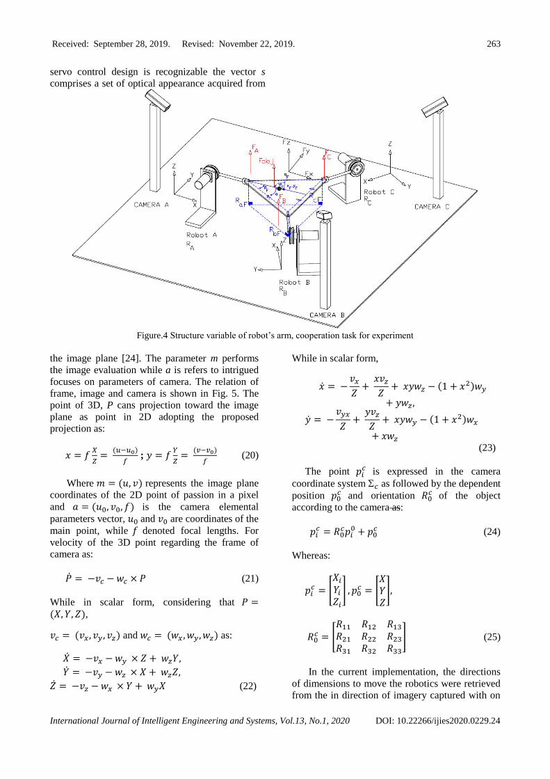
the position of the end-effector. In Fig. 4 shows the
control structure proposed in this study considering
the coordinated cooperative control of manipulators. The kinematics of robot arm taking the connection
between joint’s velocities �̇� , interrelated the end-
effector with angular velocity 𝑤𝜔 and translational
velocity 𝑤𝑣 [22]. They are related through the
geometric Jacobian 𝐽𝑔(𝑞) [23]:
[𝑤𝑣
𝑤𝜔] = 𝐽𝑔(𝑞)�̇� (18)
The end-effector (orientation and position) is
indicated via regarding an illustration in the robotics
work space; it is available to estimate the Jacobian
method through differentiation of the handle
kinematics complying to joint positions. The
Jacobian method, describe analytical of Jacobian,
𝐽𝑔(𝑞), is related to the commutative Jacobian as:
𝐽𝑔(𝑞) = [𝐼 00 𝑇(𝑞)
] 𝐽𝑔(𝑞) (19)
Where 𝑇(𝑞) is a transformation matrix that
depends on the parameter of the end-effector
orientation.
2.4 Camera visions for control of robotics
In this study, we utilized facilitates of the
intrigued focuses on the plane of image to represent
a vector. The definition of parameters established
the DC servo control scheme. The image based in
Received: September 28, 2019. Revised: November 22, 2019. 263
International Journal of Intelligent Engineering and Systems, Vol.13, No.1, 2020 DOI: 10.22266/ijies2020.0229.24
servo control design is recognizable the vector s
comprises a set of optical appearance acquired from
Figure.4 Structure variable of robot’s arm, cooperation task for experiment
the image plane [24]. The parameter m performs
the image evaluation while a is refers to intrigued
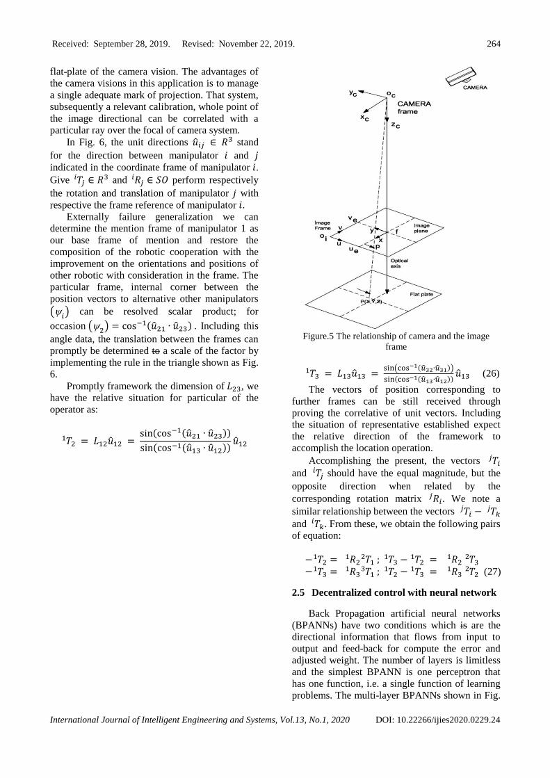
focuses on parameters of camera. The relation of
frame, image and camera is shown in Fig. 5. The
point of 3D, P cans projection toward the image
plane as point in 2D adopting the proposed
projection as:
𝑥 = 𝑓𝑋
𝑍=
(𝑢−𝑢0)
𝑓 ; 𝑦 = 𝑓
𝑌
𝑍=
(𝑣−𝑣0)
𝑓 (20)
Where 𝑚 = (𝑢, 𝑣) represents the image plane
coordinates of the 2D point of passion in a pixel
and 𝑎 = (𝑢0, 𝑣0, 𝑓) is the camera elemental
parameters vector, 𝑢0 and 𝑣0 are coordinates of the
main point, while 𝑓 denoted focal lengths. For
velocity of the 3D point regarding the frame of
camera as:
�̇� = −𝑣𝑐 − 𝑤𝑐 × 𝑃 (21)
While in scalar form, considering that 𝑃 =(𝑋, 𝑌, 𝑍),
𝑣𝑐 = (𝑣𝑥, 𝑣𝑦, 𝑣𝑧) and 𝑤𝑐 = (𝑤𝑥 , 𝑤𝑦, 𝑤𝑧) as:
�̇� = −𝑣𝑥 − 𝑤𝑦 × 𝑍 + 𝑤𝑧𝑌,
�̇� = −𝑣𝑦 − 𝑤𝑧 × 𝑋 + 𝑤𝑧𝑍,
�̇� = −𝑣𝑧 − 𝑤𝑥 × 𝑌 + 𝑤𝑦𝑋 (22)
While in scalar form,
�̇� = −𝑣𝑥
𝑍+
𝑥𝑣𝑧
𝑍+ 𝑥𝑦𝑤𝑧 − (1 + 𝑥2)𝑤𝑦
+ 𝑦𝑤𝑧,
�̇� = −𝑣𝑦𝑥
𝑍+
𝑦𝑣𝑧
𝑍+ 𝑥𝑦𝑤𝑦 − (1 + 𝑥2)𝑤𝑥
+ 𝑥𝑤𝑧
(23)
The point 𝑝𝑖𝑐 is expressed in the camera
coordinate system 𝑐 as followed by the dependent
position 𝑝0𝑐 and orientation 𝑅0
𝑐 of the object
according to the camera as:
𝑝𝑖𝑐 = 𝑅0
𝑐𝑝𝑖0 + 𝑝0
𝑐 (24)
Whereas:
𝑝𝑖𝑐 = [
𝑋𝑖
𝑌𝑖
𝑍𝑖
] , 𝑝0𝑐 = [
𝑋𝑌𝑍
],
𝑅0𝑐 = [
𝑅11 𝑅12 𝑅13
𝑅21 𝑅22 𝑅23
𝑅31 𝑅32 𝑅33
] (25)
In the current implementation, the directions
of dimensions to move the robotics were retrieved
from the in direction of imagery captured with on
Received: September 28, 2019. Revised: November 22, 2019. 264
International Journal of Intelligent Engineering and Systems, Vol.13, No.1, 2020 DOI: 10.22266/ijies2020.0229.24
flat-plate of the camera vision. The advantages of
the camera visions in this application is to manage
a single adequate mark of projection. That system,
subsequently a relevant calibration, whole point of
the image directional can be correlated with a
particular ray over the focal of camera system.
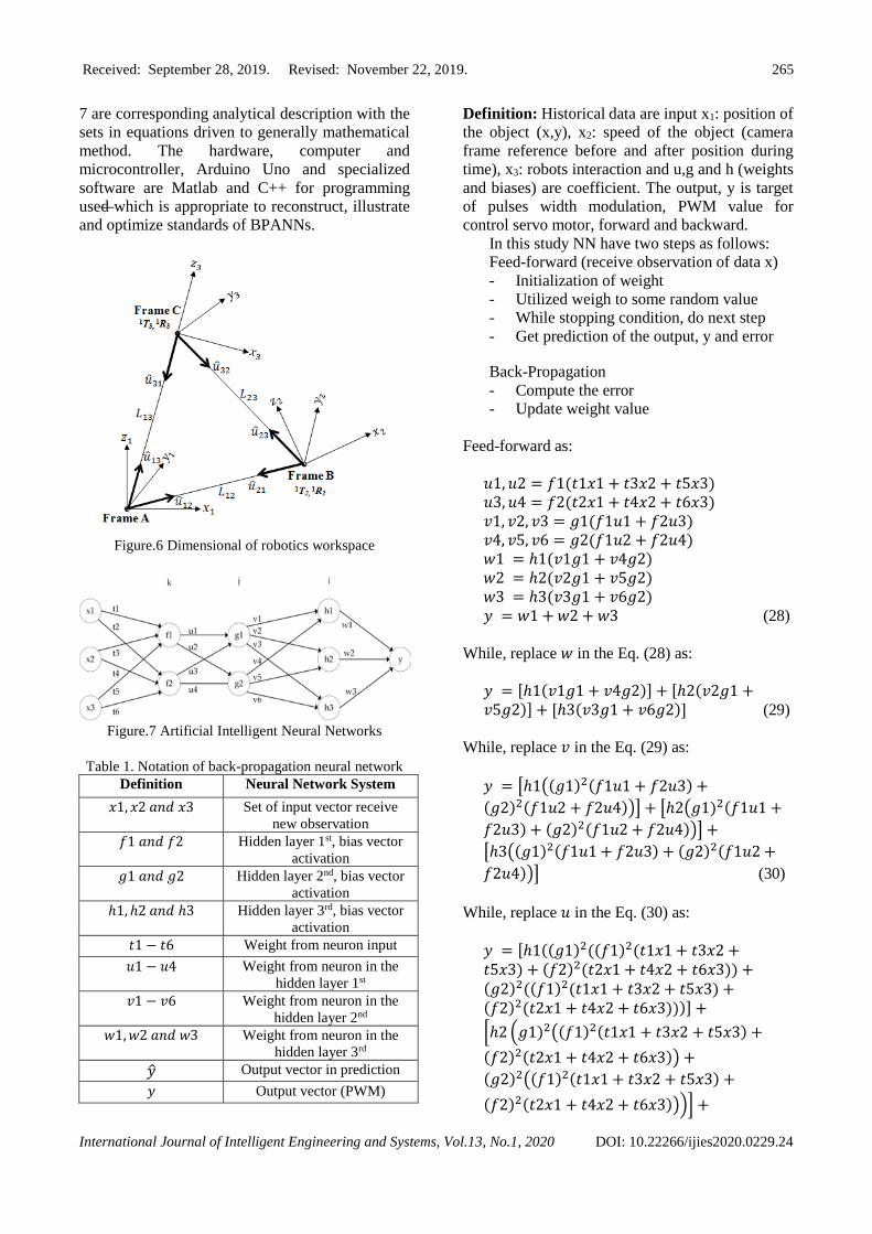
In Fig. 6, the unit directions �̂�𝑖𝑗 ∈ 𝑅3 stand
for the direction between manipulator 𝑖 and 𝑗
indicated in the coordinate frame of manipulator 𝑖. Give 𝑇𝑗 ∈ 𝑅3
𝑖 and 𝑅𝑗 ∈ 𝑆𝑂
𝑖 perform respectively
the rotation and translation of manipulator 𝑗 with
respective the frame reference of manipulator 𝑖. Externally failure generalization we can
determine the mention frame of manipulator 1 as
our base frame of mention and restore the
composition of the robotic cooperation with the
improvement on the orientations and positions of
other robotic with consideration in the frame. The
particular frame, internal corner between the
position vectors to alternative other manipulators
(𝑖) can be resolved scalar product; for
occasion (2) = cos−1(�̂�21 ∙ �̂�23) . Including this
angle data, the translation between the frames can
promptly be determined to a scale of the factor by
implementing the rule in the triangle shown as Fig.
6.
Promptly framework the dimension of 𝐿23, we
have the relative situation for particular of the
operator as:
𝑇2 1 = 𝐿12�̂�12 =
sin(cos−1(�̂�21 ∙ �̂�23))
sin(cos−1(�̂�13 ∙ �̂�12))�̂�12
Figure.5 The relationship of camera and the image
frame
𝑇3 1 = 𝐿13�̂�13 =
sin(cos−1(�̂�32∙�̂�31))
sin(cos−1(�̂�13∙�̂�12))�̂�13 (26)
The vectors of position corresponding to
further frames can be still received through
proving the correlative of unit vectors. Including
the situation of representative established expect
the relative direction of the framework to
accomplish the location operation.
Accomplishing the present, the vectors 𝑇𝑖 𝑗
and 𝑇𝑗 𝑖 should have the equal magnitude, but the
opposite direction when related by the
corresponding rotation matrix 𝑅𝑖 𝑗 . We note a
similar relationship between the vectors 𝑇𝑖 𝑗 − 𝑇𝑘
𝑗
and 𝑇𝑘 𝑖 . From these, we obtain the following pairs
of equation:
− 𝑇2 1 = 𝑅2
1 𝑇1 ; 𝑇3 1
2 − 𝑇2
1 = 𝑅2 1 𝑇3
2
− 𝑇3 1 = 𝑅3
1 𝑇1 ; 𝑇2 1
3 − 𝑇3
1 = 𝑅3 1 𝑇2
2 (27)
2.5 Decentralized control with neural network
Back Propagation artificial neural networks
(BPANNs) have two conditions which is are the
directional information that flows from input to
output and feed-back for compute the error and
adjusted weight. The number of layers is limitless
and the simplest BPANN is one perceptron that
has one function, i.e. a single function of learning
problems. The multi-layer BPANNs shown in Fig.
Received: September 28, 2019. Revised: November 22, 2019. 265
International Journal of Intelligent Engineering and Systems, Vol.13, No.1, 2020 DOI: 10.22266/ijies2020.0229.24
7 are corresponding analytical description with the
sets in equations driven to generally mathematical
method. The hardware, computer and
microcontroller, Arduino Uno and specialized
software are Matlab and C++ for programming
used which is appropriate to reconstruct, illustrate
and optimize standards of BPANNs.
Figure.6 Dimensional of robotics workspace
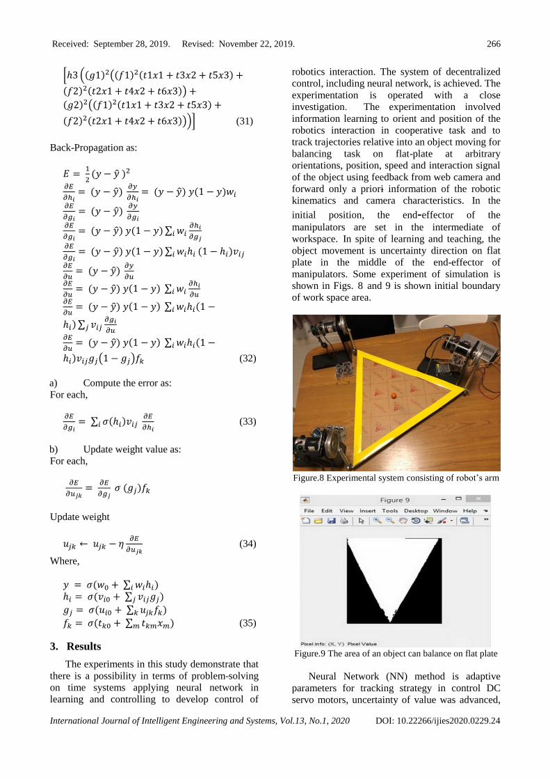
Figure.7 Artificial Intelligent Neural Networks
Table 1. Notation of back-propagation neural network
Definition Neural Network System
𝑥1, 𝑥2 𝑎𝑛𝑑 𝑥3 Set of input vector receive
new observation
𝑓1 𝑎𝑛𝑑 𝑓2 Hidden layer 1st, bias vector
activation
𝑔1 𝑎𝑛𝑑 𝑔2 Hidden layer 2nd, bias vector
activation
ℎ1, ℎ2 𝑎𝑛𝑑 ℎ3 Hidden layer 3rd, bias vector
activation
𝑡1 − 𝑡6 Weight from neuron input
𝑢1 − 𝑢4 Weight from neuron in the
hidden layer 1st
𝑣1 − 𝑣6 Weight from neuron in the
hidden layer 2nd
𝑤1, 𝑤2 𝑎𝑛𝑑 𝑤3 Weight from neuron in the
hidden layer 3rd
�̂� Output vector in prediction
𝑦 Output vector (PWM)
Definition: Historical data are input x1: position of
the object (x,y), x2: speed of the object (camera
frame reference before and after position during
time), x3: robots interaction and u,g and h (weights
and biases) are coefficient. The output, y is target
of pulses width modulation, PWM value for
control servo motor, forward and backward.
In this study NN have two steps as follows:
Feed-forward (receive observation of data x)
- Initialization of weight
- Utilized weigh to some random value
- While stopping condition, do next step
- Get prediction of the output, y and error
Back-Propagation
- Compute the error
- Update weight value
Feed-forward as:
𝑢1, 𝑢2 = 𝑓1(𝑡1𝑥1 + 𝑡3𝑥2 + 𝑡5𝑥3)
𝑢3, 𝑢4 = 𝑓2(𝑡2𝑥1 + 𝑡4𝑥2 + 𝑡6𝑥3)
𝑣1, 𝑣2, 𝑣3 = 𝑔1(𝑓1𝑢1 + 𝑓2𝑢3)
𝑣4, 𝑣5, 𝑣6 = 𝑔2(𝑓1𝑢2 + 𝑓2𝑢4)
𝑤1 = ℎ1(𝑣1𝑔1 + 𝑣4𝑔2)
𝑤2 = ℎ2(𝑣2𝑔1 + 𝑣5𝑔2)
𝑤3 = ℎ3(𝑣3𝑔1 + 𝑣6𝑔2)
𝑦 = 𝑤1 + 𝑤2 + 𝑤3 (28)
While, replace 𝑤 in the Eq. (28) as:
𝑦 = [ℎ1(𝑣1𝑔1 + 𝑣4𝑔2)] + [ℎ2(𝑣2𝑔1 +𝑣5𝑔2)] + [ℎ3(𝑣3𝑔1 + 𝑣6𝑔2)] (29)
While, replace 𝑣 in the Eq. (29) as:
𝑦 = [ℎ1((𝑔1)2(𝑓1𝑢1 + 𝑓2𝑢3) +
(𝑔2)2(𝑓1𝑢2 + 𝑓2𝑢4))] + [ℎ2(𝑔1)2(𝑓1𝑢1 +
𝑓2𝑢3) + (𝑔2)2(𝑓1𝑢2 + 𝑓2𝑢4))] +
[ℎ3((𝑔1)2(𝑓1𝑢1 + 𝑓2𝑢3) + (𝑔2)2(𝑓1𝑢2 +
𝑓2𝑢4))] (30)
While, replace 𝑢 in the Eq. (30) as:
𝑦 = [ℎ1((𝑔1)2((𝑓1)2(𝑡1𝑥1 + 𝑡3𝑥2 +𝑡5𝑥3) + (𝑓2)2(𝑡2𝑥1 + 𝑡4𝑥2 + 𝑡6𝑥3)) +(𝑔2)2((𝑓1)2(𝑡1𝑥1 + 𝑡3𝑥2 + 𝑡5𝑥3) +(𝑓2)2(𝑡2𝑥1 + 𝑡4𝑥2 + 𝑡6𝑥3)))] +
[ℎ2 (𝑔1)2((𝑓1)2(𝑡1𝑥1 + 𝑡3𝑥2 + 𝑡5𝑥3) +
(𝑓2)2(𝑡2𝑥1 + 𝑡4𝑥2 + 𝑡6𝑥3)) +
(𝑔2)2((𝑓1)2(𝑡1𝑥1 + 𝑡3𝑥2 + 𝑡5𝑥3) +
(𝑓2)2(𝑡2𝑥1 + 𝑡4𝑥2 + 𝑡6𝑥3)))] +
Received: September 28, 2019. Revised: November 22, 2019. 266
International Journal of Intelligent Engineering and Systems, Vol.13, No.1, 2020 DOI: 10.22266/ijies2020.0229.24
[ℎ3 ((𝑔1)2((𝑓1)2(𝑡1𝑥1 + 𝑡3𝑥2 + 𝑡5𝑥3) +
(𝑓2)2(𝑡2𝑥1 + 𝑡4𝑥2 + 𝑡6𝑥3)) +
(𝑔2)2((𝑓1)2(𝑡1𝑥1 + 𝑡3𝑥2 + 𝑡5𝑥3) +
(𝑓2)2(𝑡2𝑥1 + 𝑡4𝑥2 + 𝑡6𝑥3)))] (31)
Back-Propagation as:
𝐸 = 1
2(𝑦 − �̂� )2
𝜕𝐸
𝜕ℎ𝑖= (𝑦 − �̂�)
𝜕𝑦
𝜕ℎ𝑖 = (𝑦 − �̂�) 𝑦(1 − 𝑦)𝑤𝑖
𝜕𝐸
𝜕𝑔𝑖= (𝑦 − �̂�)
𝜕𝑦
𝜕𝑔𝑖
𝜕𝐸
𝜕𝑔𝑖= (𝑦 − �̂�) 𝑦(1 − 𝑦) ∑ 𝑤𝑖
𝜕ℎ𝑖
𝜕𝑔𝑗𝑖
𝜕𝐸
𝜕𝑔𝑖= (𝑦 − �̂�) 𝑦(1 − 𝑦) ∑ 𝑤𝑖ℎ𝑖𝑖 (1 − ℎ𝑖)𝑣𝑖𝑗
𝜕𝐸
𝜕𝑢= (𝑦 − �̂�)
𝜕𝑦
𝜕𝑢
𝜕𝐸
𝜕𝑢= (𝑦 − �̂�) 𝑦(1 − 𝑦) ∑ 𝑤𝑖
𝜕ℎ𝑖
𝜕𝑢𝑖
𝜕𝐸
𝜕𝑢= (𝑦 − �̂�) 𝑦(1 − 𝑦) ∑ 𝑤𝑖ℎ𝑖(1 −𝑖
ℎ𝑖) ∑ 𝑣𝑖𝑗𝜕𝑔𝑖
𝜕𝑢𝑗
𝜕𝐸
𝜕𝑢= (𝑦 − �̂�) 𝑦(1 − 𝑦) ∑ 𝑤𝑖ℎ𝑖(1 −𝑖
ℎ𝑖)𝑣𝑖𝑗𝑔𝑗(1 − 𝑔𝑗)𝑓𝑘 (32)
a) Compute the error as:
For each,
𝜕𝐸
𝜕𝑔𝑖= ∑ 𝜎(ℎ𝑖)𝑣𝑖𝑗 𝑖
𝜕𝐸
𝜕ℎ𝑖 (33)
b) Update weight value as:
For each,
𝜕𝐸
𝜕𝑢𝑗𝑘=
𝜕𝐸
𝜕𝑔𝑗 𝜎 (𝑔𝑗)𝑓𝑘
Update weight
𝑢𝑗𝑘 ← 𝑢𝑗𝑘 − 𝜂𝜕𝐸
𝜕𝑢𝑗𝑘 (34)
Where,
𝑦 = 𝜎(𝑤0 + ∑ 𝑤𝑖ℎ𝑖𝑖 )
ℎ𝑖 = 𝜎(𝑣𝑖0 + ∑ 𝑣𝑖𝑗𝑔𝑗𝑗 )
𝑔𝑗 = 𝜎(𝑢𝑖0 + ∑ 𝑢𝑗𝑘𝑓𝑘𝑘 )
𝑓𝑘 = 𝜎(𝑡𝑘0 + ∑ 𝑡𝑘𝑚𝑥𝑚𝑚 ) (35)
3. Results
The experiments in this study demonstrate that
there is a possibility in terms of problem-solving
on time systems applying neural network in
learning and controlling to develop control of
robotics interaction. The system of decentralized
control, including neural network, is achieved. The
experimentation is operated with a close
investigation. The experimentation involved
information learning to orient and position of the
robotics interaction in cooperative task and to
track trajectories relative into an object moving for
balancing task on flat-plate at arbitrary
orientations, position, speed and interaction signal
of the object using feedback from web camera and
forward only a priori information of the robotic
kinematics and camera characteristics. In the
initial position, the end-effector of the
manipulators are set in the intermediate of
workspace. In spite of learning and teaching, the
object movement is uncertainty direction on flat
plate in the middle of the end-effector of
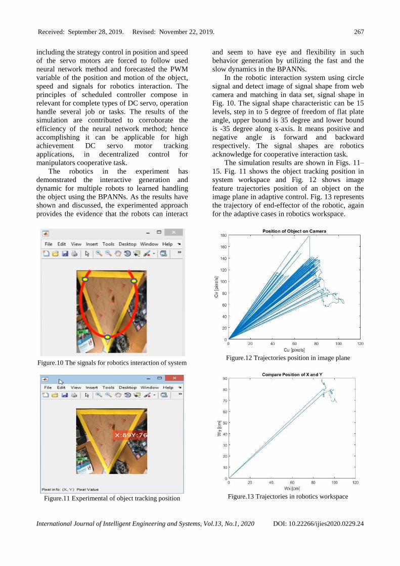
manipulators. Some experiment of simulation is
shown in Figs. 8 and 9 is shown initial boundary
of work space area.
Figure.8 Experimental system consisting of robot’s arm
Figure.9 The area of an object can balance on flat plate
Neural Network (NN) method is adaptive
parameters for tracking strategy in control DC
servo motors, uncertainty of value was advanced,
Received: September 28, 2019. Revised: November 22, 2019. 267
International Journal of Intelligent Engineering and Systems, Vol.13, No.1, 2020 DOI: 10.22266/ijies2020.0229.24
including the strategy control in position and speed
of the servo motors are forced to follow used
neural network method and forecasted the PWM
variable of the position and motion of the object,
speed and signals for robotics interaction. The
principles of scheduled controller compose in
relevant for complete types of DC servo, operation
handle several job or tasks. The results of the
simulation are contributed to corroborate the
efficiency of the neural network method; hence
accomplishing it can be applicable for high
achievement DC servo motor tracking
applications, in decentralized control for
manipulators cooperative task.
The robotics in the experiment has
demonstrated the interactive generation and
dynamic for multiple robots to learned handling
the object using the BPANNs. As the results have
shown and discussed, the experimented approach
provides the evidence that the robots can interact
Figure.10 The signals for robotics interaction of system
Figure.11 Experimental of object tracking position
and seem to have eye and flexibility in such
behavior generation by utilizing the fast and the
slow dynamics in the BPANNs.
In the robotic interaction system using circle
signal and detect image of signal shape from web
camera and matching in data set, signal shape in
Fig. 10. The signal shape characteristic can be 15
levels, step in to 5 degree of freedom of flat plate
angle, upper bound is 35 degree and lower bound
is -35 degree along x-axis. It means positive and
negative angle is forward and backward
respectively. The signal shapes are robotics
acknowledge for cooperative interaction task.
The simulation results are shown in Figs. 11–
15. Fig. 11 shows the object tracking position in
system workspace and Fig. 12 shows image
feature trajectories position of an object on the
image plane in adaptive control. Fig. 13 represents
the trajectory of end-effector of the robotic, again
for the adaptive cases in robotics workspace.
Figure.12 Trajectories position in image plane
Figure.13 Trajectories in robotics workspace
Received: September 28, 2019. Revised: November 22, 2019. 268
International Journal of Intelligent Engineering and Systems, Vol.13, No.1, 2020 DOI: 10.22266/ijies2020.0229.24
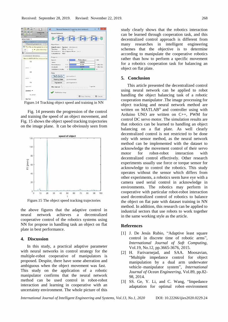
Figure.14 Tracking object speed and training in NN
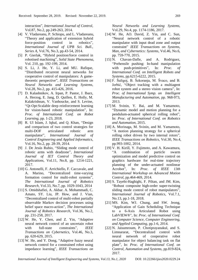
Fig. 14 presents the progression of the control
and training the speed of an object movement, and
Fig. 15 shows the object speed tracking trajectories
on the image plane. It can be obviously seen from
Figure.15 The object speed tracking trajectories
the above figures that the adaptive control in
neural network achieves a decentralized
cooperative control of the robotics systems using
NN for propose in handling task an object on flat
plate in best performance.
4. Discussion
In this study, a practical adaptive parameter
with neural networks in control strategy for the
multiple-robot cooperative of manipulators is
proposed. Despite, there have some aberration and
ambiguous when the object movement was fast. This study on the application of a robotic
manipulator confirms that the neural network
method can be used control in robot-robot
interaction and learning in cooperative with an
uncertainty environment. The whole picture of this
study clearly shows that the robotics interaction
can be learned through cooperation task, and this
decentralized control approach is different from
many researches in intelligent engineering
schemes that the objective is to determine
according to manipulate the cooperative robotics
rather than how to perform a specific movement
for a robotics cooperation task for balancing an
object on flat plate.
5. Conclusion
This article presented the decentralized control
using neural network can be applied to robot
handling the object balancing task of a robotic
cooperation manipulator .The image processing for
object tracking and neural network method are
written on MATLAB® and controller using with
Arduino UNO are written on C++, PWM for
control DC servo motor. The simulation results are
that robotics can be learned to handling an object
balancing on a flat plate. As well clearly
decentralized control is not restricted to be done
only with sensor method, as the neural network
method can be implemented with the dataset to
acknowledge the movement control of their servo
motor for robot-robot interaction with
decentralized control effectively. Other research
experiments usually use force or torque sensor for
acknowledge to control the robotics. This study
operates without the sensor which differs from
other experiments, a robotics seem have eye with a
camera used serial control in acknowledge in
environments. The robotics may perform in
cooperative with particular robot-robot interaction
used decentralized control of robotics to balance
the object on flat pate with dataset training in NN
method. In addition, this research can be applied to
industrial sectors that use robots to work together
in the same working style as the article.
References
[1] J. De Jesús Rubio, “Adaptive least square
control in discrete time of robotic arms”,
International Journal of Soft Computing,
Vol.19, No.12, pp.3665-3676, 2015.
[2] H. Farivarnejad, and SAA. Moosavian,
“Multiple impedance control for object
manipulation by a dual arm underwater
vehicle–manipulator system”, International
Journal of Ocean Engineering, Vol.89, pp.82-
98, 2014.
[3] SS. Ge, Y. Li, and C. Wang, “Impedance
adaptation for optimal robot–environment
Received: September 28, 2019. Revised: November 22, 2019. 269
International Journal of Intelligent Engineering and Systems, Vol.13, No.1, 2020 DOI: 10.22266/ijies2020.0229.24
interaction”, International Journal of Control,
Vol.87, No.2, pp.249-263, 2014.
[4] V. Vladareanu, P. Schiopu, and L. Vladareanu,
“Theory and application of extension hybrid
force-position control in robotics”,
International Journal of UPB Sci. Bull.,
Series A, Vol.76, No.3, pp.43-54, 2014.
[5] P. Gierlak, “Hybrid position/force control in
robotised machining”, Solid State Phenomena,
Vol. 210, pp. 192-199, 2014.
[6] S. Li, J. He, Y. Li, and MU. Rafique,
“Distributed recurrent neural networks for
cooperative control of manipulators: A game-
theoretic perspective”, IEEE Transactions on
Neural Networks and Learning Systems,
Vol.28, No.2, pp. 415-426, 2016.
[7] D. Kalashnikov, A. Irpan, P. Pastor, J. Ibarz,
A. Herzog, E. Jang, D. Quillen, E. Holly, M.
Kalakrishnan, V. Vanhoucke, and S. Levine,
“Qt-Opt:Scalable deep reinforcement learning
for vision-based robotic manipulation”, In:
Proc. of International Conf. on Robot
Learning, pp. 1-23, 2018.
[8] R. Ul Islam, J. Iqbal, and Q. Khan, “Design
and comparison of two control strategies for
multi-DOF articulated robotic arm
manipulator”, International Journal of
Control Engineering and Applied Informatics,
Vol.16, No.2, pp. 28-39, 2014.
[9] J. De Jesús Rubio, “Sliding mode control of
robotic arms with deadzone”, International
Journal of IET Control Theory and
Applications, Vol.11, No.8, pp. 1214-1221,
2017.
[10] G. Antonelli, F. Arrichiello, F. Caccavale, and
A. Marino, “Decentralized time-varying
formation control for multi-robot systems”,
The International Journal of Robotics
Research, Vol.33, No.7, pp. 1029-1043, 2014
[11] S. Omidshafiei, A. Akbar. A. Mohammadi, C.
Amato, SY. Liu, JP. How, and J. Vian,
“Decentralized control of multi-robot partially
observable Markov decision processes using
belief space macro-action”, The International
Journal of Robotics Research, Vol.36, No.2,
pp. 231-258, 2017.
[12] W. He, Y. Chen, and Z. Yin, “Adaptive
neural network control of an uncertain robot
with full-state constraints”, IEEE
Transactions on Cybernetics, Vol.46, No.3,
pp. 620-629, 2015.
[13] W. He, and Y. Dong, “Adaptive fuzzy neural
network control for a constrained robot using
impedance learning”, IEEE Transactions on
Neural Networks and Learning Systems,
Vol.29, No.4, pp. 1174-1186, 2017.
[14] W. He, AO. David, Z. Yin, and C. Sun,
“Neural network control of a robotic
manipulator with input dead zone and output
constraint” IEEE Transactions on Systems,
Man, and Cybernetics: Systems, Vol.46, No.6,
pp. 759-770, 2015.
[15] N. Chavan-Dafle, and A. Rodriguez,
“Prehensile pushing: In-hand manipulation
with push-primitives”, In: Proc. of
International Conf. on Intelligent Robots and
Systems, pp.6215-6222, 2015.
[16] F. Šuligoj, B. Šekoranja, M. Švaco, and B.
Jerbić, “Object tracking with a multiagent
robot system and a stereo vision camera”, In:
Proc. of International Symp. on Intelligent
Manufacturing and Automation, pp. 968-973,
2013.
[17] M. Svinin, Y. Bai, and M. Yamamoto,
“Dynamic model and motion planning for a
pendulum-actuated spherical rolling robot”,
In: Proc. of International Conf. on Robotics
and Automation, 2015.
[18] A. Morinaga, M. Svinin, and M. Yamamoto,
“A motion planning strategy for a spherical
rolling robot driven by two internal rotors”,
IEEE Transactions on Robotics, Vol.30, No.4,
pp.993-1002, 2014.
[19] V. H. Kirill, Y. Fujimoto, and A. Kawamura,
“A combination of particle swarm
optimization and model predictive control on
graphics hardware for real-time trajectory
planning of the under-actuated nonlinear
Acrobot”, In: Proc. of IEEE 13th
International Workshop on Advanced Motion
Control, pp.464-469, 2014.
[20] S. Tayebi-Haghighi, F. Piltan, and JM. Kim,
“Robust composite high-order super-twisting
sliding mode control of robot manipulators”,
International Journal of Robotics, Vol.7.1,
No.13, pp.1-18, 2018.
[21] MS. Kim, WJ. Chung, and SW. Jeong,
“Application of Gain Scheduling Technique
to a 6-Axis Articulated Robot using
LabVIEW®", In: Proc. of International Conf.
on Computer Science, Computer Engineering,
and Applied Computing, pp.1-6, 2014.
[22] N. Jaisumroum, P. Chotiprayanakul, and S.
Limnararat, “Decentralized control with
neural network of cooperative robot
manipulator for object balancing task on flat
plate”, In: Proc. of International Conf. on
Control, Automation and Systems, pp.819-824,
2017.
Received: September 28, 2019. Revised: November 22, 2019. 270
International Journal of Intelligent Engineering and Systems, Vol.13, No.1, 2020 DOI: 10.22266/ijies2020.0229.24
[23] N. Jaisumroum, P. Chotiprayanakul, and S.
Limnararat, “A conceptual framework of
decentralized learning neural network control
approach for multi-robot cooperation in an
object balancing task”, In: Proc. of
International Conf. on Industrial Engineering
and Engineering Management, pp. 434-437,
2016.
[24] P. Corke, Robotics, vision and control:
fundamental algorithms in MATLAB® second,
completely revised, Vol. 118. Springer
International Publishing, Verlag Berlin
Heidelberg, New York, N.Y.2017.