Embed Size (px)
Citation preview
J1
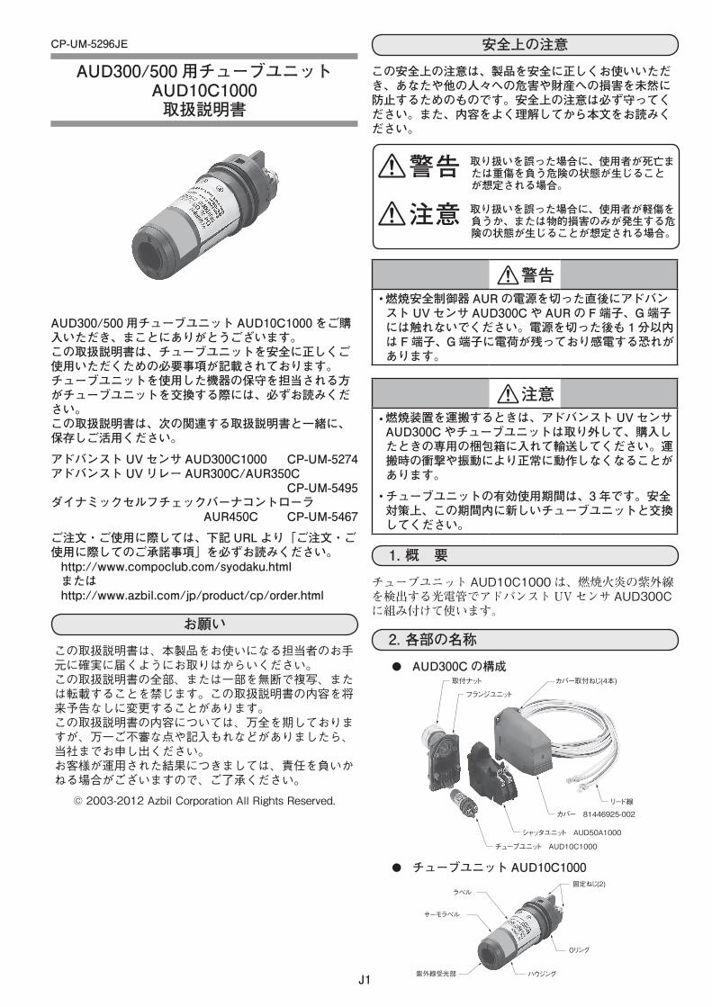
CP-UM-XXXX
XXXXXXXXXXX取扱説明書
AUD300/500 用チューブユニットAUD10C1000 をご購入いただき、まことにありがとうございます。この取扱説明書は、チューブユニットを安全に正しくご使用いただくための必要事項が記載されております。チューブユニットを使用した機器の保守を担当される方がチューブユニットを交換する際には、必ずお読みください。この取扱説明書は、次の関連する取扱説明書と一緒に、保存しご活用ください。
アドバンストUVセンサ AUD300C1000 CP-UM-5274アドバンストUVリレー AUR300C/AUR350C CP-UM-5495ダイナミックセルフチェックバーナコントローラ AUR450C CP-UM-5467
ご注文・ご使用に際しては、下記URLより「ご注文・ご使用に際してのご承諾事項」を必ずお読みください。http://www.compoclub.com/syodaku.htmlまたはhttp://www.azbil.com/jp/product/cp/order.html
お願い
この取扱説明書は、本製品をお使いになる担当者のお手元に確実に届くようにお取りはからいください。この取扱説明書の全部、または一部を無断で複写、または転載することを禁じます。この取扱説明書の内容を将来予告なしに変更することがあります。この取扱説明書の内容については、万全を期しておりますが、万一ご不審な点や記入もれなどがありましたら、当社までお申し出ください。お客様が運用された結果につきましては、責任を負いかねる場合がございますので、ご了承ください。
© 2003-2012 Azbil Corporation All Rights Reserved.
安全上の注意
この安全上の注意は、製品を安全に正しくお使いいただき、あなたや他の人々への危害や財産への損害を未然に防止するためのものです。安全上の注意は必ず守ってください。また、内容をよく理解してから本文をお読みください。
警告燃焼安全制御器AURの電源を切った直後にアドバン•スト UVセンサ AUD300Cや AURの F端子、G端子には触れないでください。電源を切った後も 1分以内は F端子、G端子に電荷が残っており感電する恐れがあります。
注意燃焼装置を運搬するときは、アドバンストUVセンサ•AUD300Cやチューブユニットは取り外して、購入したときの専用の梱包箱に入れて輸送してください。運搬時の衝撃や振動により正常に動作しなくなることがあります。
チューブユニットの有効使用期間は、3年です。安全•対策上、この期間内に新しいチューブユニットと交換してください。
1.概 要
チューブユニット AUD10C1000は、燃焼火炎の紫外線を検出する光電管でアドバンストUVセンサ AUD300Cに組み付けて使います。
2.各部の名称
AUD300Cの構成●取付ナット
フランジユニット
リード線
カバー取付ねじ(4本)
カバー 81446925-002
シャッタユニット AUD50A1000
チューブユニット AUD10C1000
チューブユニットAUD10C1000●
ラベル
サーモラベル
紫外線受光部 ハウジング
Oリング
固定ねじ(2)
警告 取り扱いを誤った場合に、使用者が死亡または重傷を負う危険の状態が生じることが想定される場合。
注意 取り扱いを誤った場合に、使用者が軽傷を負うか、または物的損害のみが発生する危険の状態が生じることが想定される場合。
CP-UM-5296JE
AUD300/500 用チューブユニットAUD10C1000取扱説明書

J2
〔ご注意〕 この資料の記載内容は、お断りなく変更する場合もありますので ご了承ください。 (24)
本 社 〒100-6419 東京都千代田区丸の内 2-7-3 東京ビル北海道支店東 北 支 店北関東支店東 京 支 社
中 部 支 社関 西 支 社中 国 支 店九 州 支 社
☎(011)781 ー 5396☎(022)290 ー 1400☎(048)621 ー 5070☎(03)6810 ー 1211~2
☎(052)324 ー 9772☎(06)6881 ー 3383~4☎(082)554 ー 0750☎(093)285 ー 3530
〈COMPO CLUB〉 http://www.compoclub.com〈アズビル株式会社〉 http://www.azbil.com/jp/
製品のお問い合わせは… コールセンター : 0466-20-2143
2003年 1月 初版発行(E )2012年 4月 改訂6版(M)
3.チューブユニットの交換
取り扱い上の注意交換作業の際には、チューブユニットに衝撃を• 与えないように、ていねいに取り扱ってください。持ち運びや保管するときは、必ず購入したとき• の専用の梱包箱に入れてください。アドバンスト UV センサ AUD300C の使用温度• 範囲の上限は 120℃です。高温で使用する場合やチューブユニットのサーモラベルの 120℃の部分が黒くなっている場合は、周囲温度を確認しエアパージなどで冷却してください。交換作業が終わってカバ−を取り付けるとき、• フランジユニットの O リングは確実に取り付けてください。シール性が保てなくなります。端子ねじや取付ねじは、締付トルク 0.7N・m で• 締め付けてください。
①燃焼安全制御器 AURの電源を切ってください。②1 分以上経過してから取付ナットを緩めて、アドバンストUVセンサ AUD300Cを監視パイプから取り外してください。
③AUD300Cのカバー取付ねじ 4本を外し、カバーを取り外してください。
④チューブユニット後部のチューブユニット固定ねじ 2本を外してください。
⑤チューブユニット後部を持ち、静かに上方に持ち上げて取り外してください。
⑥新しいチューブユニットの先端をシャッタユニット上部の丸穴に差し込み、後部を押し下げるようにして取り付けます。
取付ナット
Oリング
フランジユニット
ケーブルガイド
カバー取付ねじ(4か所)
チューブユニットチューブユニット固定ねじ(2か所)G端子(黄色リード線)F端子(青色リード線)
取扱い上の注意チューブユニットには極性があります。取り付けてあるシャッタユニット AUD50A1000 の上部の極性表示ラベル F、G にあわせて正しく取り付けてください。また、シャッタユニットにはチューブユニットに合わせて段差が設けてあります。逆向きに取り付きませんが、無理に組み付けようとしないでください。
⑦チューブユニット固定ねじ 2本を締め付けてください。
⑧Oリングがフランジユニットから外れていないか確認してください。
⑨カバーをカバー取付ねじ 4本で固定してください。
4.動作確認
燃焼安全制御器 AURのフレーム電圧出力端子でチューブユニットの動作を確認します。
-+
AUR出力端子
黒赤
DC 0~7.5Vレンジ入力インピーダンス100kΩ以上
15μA7.5V
5
105
2.5
00
レコーダ
7.5V
7.5VSPL15UA
OFF
TAUT BAND
μA・V
FSP136A100または相当品
①AURのフレーム電圧出力端子に FSP136A100または相当品を接続してください。
②AUD300Cの紫外線受光部の直前でライターなどを点火し、フレーム電圧が出ることを確認します。
取り扱い上の注意火気使用時は、周囲に可燃ガスがないことを確認してください。
③監視パイプに AUD300Cを取り付けてください。④バーナを燃焼させてください。⑤テスターで AURの端子間のフレーム電圧を測定してください。
推奨フレーム電圧 点検項目DC2.0V 以上で安定していること(本器のシャッタ動作に同期して、0.1 〜 0.3V の範囲でフレーム電圧が変動します)
炎の監視が正しいか本器の受光部レンズが汚れていないか監視パイプにすすなどが詰まっていないか
5.点検・調整
チューブユニットを交換したときは、チューブユニットの機能をチェックするために、パイロットターンダウンテスト、点火スパーク応答テスト、安全遮断テストは確実に行ってください。
それぞれのテストの詳細は アドバンスト UV リレー AUR300C/AUR350C CP-UM-5495
ダイナミックセルフチェックバーナコントローラ AUR450C CP-UM-5467 をご覧ください。
CP-UM-XXXXE
XXXX(形番)XXXXXXX(製品名称)
User's Manual
E1
Thank you for purchasing the AUD10C1000. This manual contains information for ensuring correct use of the AUD10C1000. This manual should be read by any personnel who are responsible for the maintenance of devices that are installed with the tube unit. Keep this manual in an easily accessible place with the following related manuals:AUD300C1000 Advanced Ultraviolet Flame Detector CP-SP-1141EAUR300C Advanced Ultraviolet Burner Controller CP-SP-1142EAUR350C Advanced Ultraviolet Burner Controller CP-SP-1175EAUR450C Dynamic Self-Checking Burner Controller CP-SP-1264EPlease read the "Terms and Conditions" from the following URL before ordering or use:http://www.azbil.com/products/bi/order.html
NOTICE
Be sure that the user receives this manual before the product is used.Copying or duplicating this user’s manual in part or in whole is forbidden. The information and specifications in this manual are subject to change without notice.Considerable effort has been made to ensure that this manual is free from inaccuracies and omissions. If you should find an error or omission, please contact the azbil Group.In no event is Azbil Corporation liable to anyone for any indirect, special or consequential damages as a result of using this product.
© 2005-2012 Azbil Corporation All Rights Reserved.
SAFETY PRECAUTIONS
Safety precautions are for ensuring safe and correct use of this product, and for preventing injury to the operator and other people or damage to property. You must observe these safety precautions. Also, be sure to read and understand the contents of this user's manual.
WARNINGWarnings are indicated when mishandling this product might result in death or serious injury to the user.
CAUTIONCautions are indicated when mishandling this product might result in minor injury to the user, or only physical damage to this product.
WARNINGDo not touch this unit or the F-terminal or G-terminal of •the AUR immediately after the power to the AUR has been turned OFF. The F-terminal or G-terminal are still electrically alive within 1 min after the power has been turned OFF, causing an electric shock hazard.
CAUTIONWhen transporting combustion equipment, uninstall •the AUD300C Advanced Ultraviolet Flame Detector and the tube unit, and ship them in the same packaging that they were in when they were received. Failure to do so could result in faulty operation incurred from shock or vibration during shipping.The service life of the AUD10C1000 tube unit is a •maximum of 3 years. To ensure operational safety, replace the tube unit with a new one within this service life.
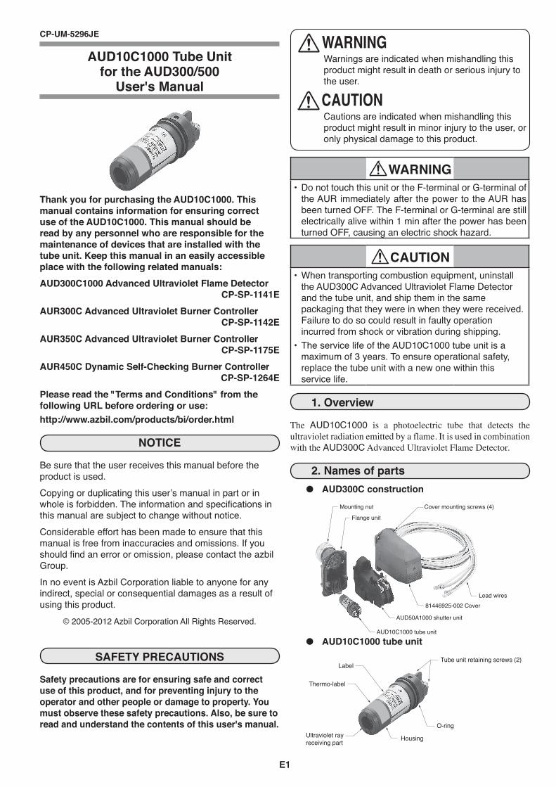
1. Overview
The AUD10C1000 is a photoelectric tube that detects the ultraviolet radiation emitted by a flame. It is used in combination with the AUD300C Advanced Ultraviolet Flame Detector.
2. Names of partsAUD300C construc ● tion
Mounting nut
Flange unit
Lead wires
Cover mounting screws (4)
81446925-002 Cover
AUD50A1000 shutter unit
AUD10C1000 tube unit
AUD10C1000 tube unit ●
Label
Thermo-label
Ultraviolet rayreceiving part Housing
O-ring
Tube unit retaining screws (2)
CP-UM-5296JE
AUD10C1000 Tube Unit for the AUD300/500
User's Manual
E2
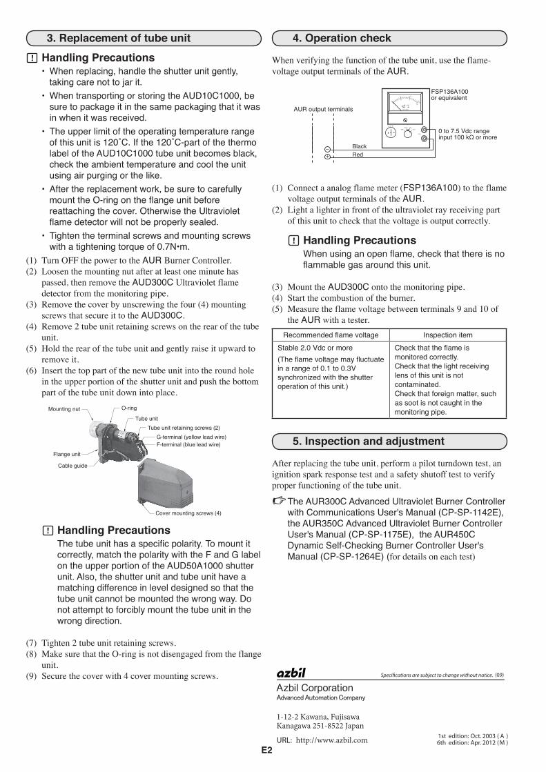
4. Operation check
When verifying the function of the tube unit, use the flame-voltage output terminals of the AUR.
-+
AUR output terminals
BlackRed
0 to 7.5 Vdc range input 100 kΩ or more
FSP136A100or equivalent
(1) Connect a analog flame meter (FSP136A100) to the flame voltage output terminals of the AUR.
(2) Light a lighter in front of the ultraviolet ray receiving part of this unit to check that the voltage is output correctly.
Handling PrecautionsWhen using an open flame, check that there is no flammable gas around this unit.
(3) Mount the AUD300C onto the monitoring pipe.(4) Start the combustion of the burner.(5) Measure the flame voltage between terminals 9 and 10 of
the AUR with a tester.Recommended flame voltage Inspection item
Stable 2.0 Vdc or more(The flame voltage may fluctuate in a range of 0.1 to 0.3V synchronized with the shutter operation of this unit.)
Check that the flame is monitored correctly.Check that the light receiving lens of this unit is not contaminated.Check that foreign matter, such as soot is not caught in the monitoring pipe.
5. Inspection and adjustment
After replacing the tube unit, perform a pilot turndown test, an ignition spark response test and a safety shutoff test to verify proper functioning of the tube unit.
The AUR300C Advanced Ultraviolet Burner Controller with Communications User's Manual (CP-SP-1142E), the AUR350C Advanced Ultraviolet Burner Controller User's Manual (CP-SP-1175E), the AUR450C Dynamic Self-Checking Burner Controller User's Manual (CP-SP-1264E) (for details on each test)
3. Replacement of tube unit
Handling PrecautionsWhen replacing, handle the shutter unit gently, •taking care not to jar it. When transporting or storing the AUD10C1000, be •sure to package it in the same packaging that it was in when it was received.The upper limit of the operating temperature range •ofthisunitis120˚C.Ifthe120˚C-partofthethermolabel of the AUD10C1000 tube unit becomes black, check the ambient temperature and cool the unit using air purging or the like.After the replacement work, be sure to carefully •mount the O-ring on the flange unit before reattaching the cover. Otherwise the Ultraviolet flame detector will not be properly sealed.Tighten the terminal screws and mounting screws •withatighteningtorqueof0.7N•m.
(1) Turn OFF the power to the AUR Burner Controller.(2) Loosen the mounting nut after at least one minute has
passed, then remove the AUD300C Ultraviolet flame detector from the monitoring pipe.
(3) Remove the cover by unscrewing the four (4) mounting screws that secure it to the AUD300C.
(4) Remove 2 tube unit retaining screws on the rear of the tube unit.
(5) Hold the rear of the tube unit and gently raise it upward to remove it.
(6) Insert the top part of the new tube unit into the round hole in the upper portion of the shutter unit and push the bottom part of the tube unit down into place.
Mounting nut O-ring
Flange unit
Cable guide
Cover mounting screws (4)
Tube unitTube unit retaining screws (2)
G-terminal (yellow lead wire)F-terminal (blue lead wire)
Handling PrecautionsThe tube unit has a specific polarity. To mount it correctly, match the polarity with the F and G label on the upper portion of the AUD50A1000 shutter unit. Also, the shutter unit and tube unit have a matching difference in level designed so that the tube unit cannot be mounted the wrong way. Do not attempt to forcibly mount the tube unit in the wrong direction.
(7) Tighten 2 tube unit retaining screws.(8) Make sure that the O-ring is not disengaged from the flange
unit.(9) Secure the cover with 4 cover mounting screws. (09)
1-12-2 Kawana, FujisawaKanagawa 251-8522 Japan
URL: http://www.azbil.com
Speci�cations are subject to change without notice.
1st edition: Oct. 2003 ( A )6th edition: Apr. 2012 (M )