Embed Size (px)
DESCRIPTION
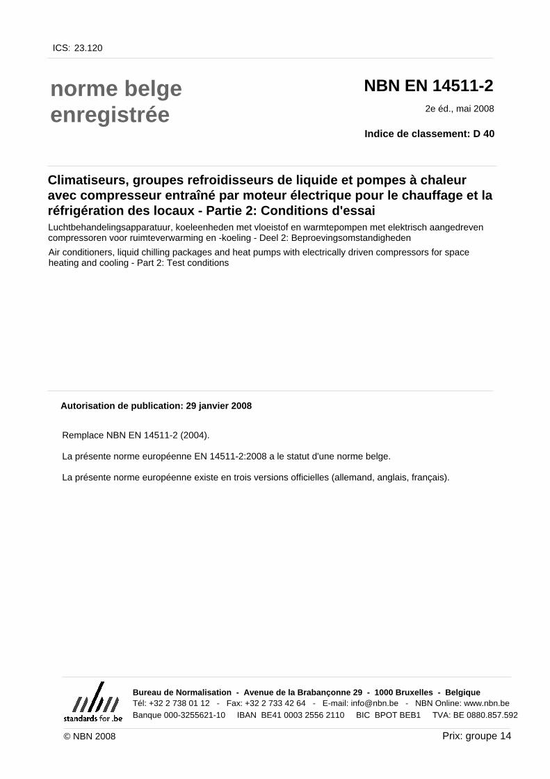
Air conditioners, liquid chilling packages and heat pumps with electrically driven compressors for space heating and cooling
Citation preview

GeregistreerdeBelgische norm
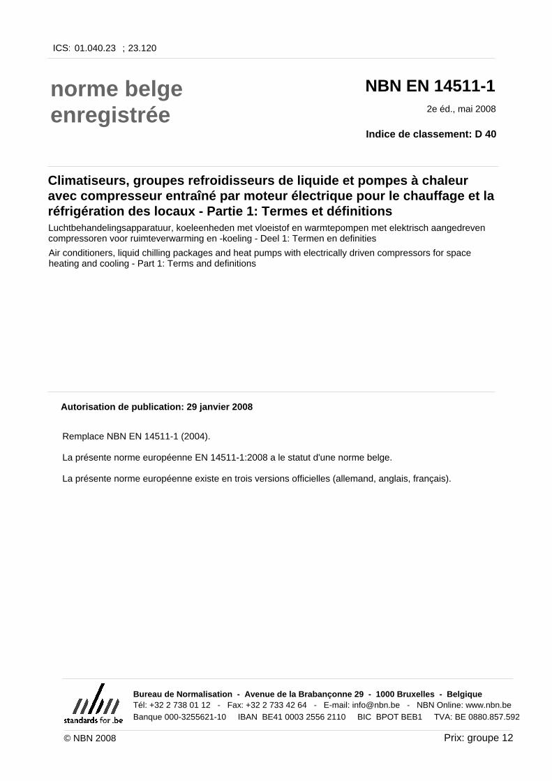
NBN EN 14511-1
Luchtbehandelingsapparatuur, koeleenheden met vloeistof enwarmtepompen met elektrisch aangedreven compressoren voorruimteverwarming en -koeling - Deel 1: Termen en definitiesClimatiseurs, groupes refroidisseurs de liquide et pompes à chaleur avec compresseur entraîné par moteurélectrique pour le chauffage et la réfrigération des locaux - Partie 1: Termes et définitions
2e uitg., mei 2008
Normklasse: D 40
Air conditioners, liquid chilling packages and heat pumps with electrically driven compressors for spaceheating and cooling - Part 1: Terms and definitions
Prijsgroep: 12
Toelating tot publicatie: 29 januari 2008
Vervangt NBN EN 14511-1 (2004).
Deze Europese norm EN 14511-1:2008 heeft de status van een Belgische norm.
Deze Europese norm bestaat in drie officiële versies (Duits, Engels, Frans).
© NBN 2008
ICS: 01.040.23 23.120;
Bureau voor Normalisatie Brabançonnelaan 29 B-1000 Brussel BelgiëTel: +32 2 738 01 12 - Fax: +32 2 733 42 64 - E-mail: [email protected] - NBN Online: www.nbn.beBank 000-3255621-10 IBAN BE41 0003 2556 2110 BIC BPOT BEB1 BTW: BE 0880.857.592
ICS: 01.040.23 23.120;
norme belgeenregistrée
NBN EN 14511-1
Climatiseurs, groupes refroidisseurs de liquide et pompes à chaleuravec compresseur entraîné par moteur électrique pour le chauffage et laréfrigération des locaux - Partie 1: Termes et définitionsLuchtbehandelingsapparatuur, koeleenheden met vloeistof en warmtepompen met elektrisch aangedrevencompressoren voor ruimteverwarming en -koeling - Deel 1: Termen en definities
2e éd., mai 2008
Indice de classement: D 40
Air conditioners, liquid chilling packages and heat pumps with electrically driven compressors for spaceheating and cooling - Part 1: Terms and definitions
Autorisation de publication: 29 janvier 2008
Remplace NBN EN 14511-1 (2004).
La présente norme européenne EN 14511-1:2008 a le statut d'une norme belge.
La présente norme européenne existe en trois versions officielles (allemand, anglais, français).
Prix: groupe 12© NBN 2008
Bureau de Normalisation - Avenue de la Brabançonne 29 - 1000 Bruxelles - BelgiqueTél: +32 2 738 01 12 - Fax: +32 2 733 42 64 - E-mail: [email protected] - NBN Online: www.nbn.beBanque 000-3255621-10 IBAN BE41 0003 2556 2110 BIC BPOT BEB1 TVA: BE 0880.857.592
EUROPEAN STANDARD
NORME EUROPÉENNE
EUROPÄISCHE NORM
EN 14511-1
November 2007
ICS 23.120; 01.040.23 Supersedes EN 14511-1:2004
English Version
Air conditioners, liquid chilling packages and heat pumps withelectrically driven compressors for space heating and cooling -
Part 1: Terms and definitions
Climatiseurs, groupes refroidisseurs de liquide et pompes àchaleur avec compresseur entraîné par moteur électriquepour le chauffage et la réfrigération des locaux - Partie 1:
Termes et définitions
Luftkonditionierer, Flüssigkeitskühlsätze undWärmepumpen mit elektrisch angetriebenen Verdichtern
für die Raumbeheizung und Kühlung - Teil 1: Begriffe
This European Standard was approved by CEN on 13 October 2007.
CEN members are bound to comply with the CEN/CENELEC Internal Regulations which stipulate the conditions for giving this EuropeanStandard the status of a national standard without any alteration. Up-to-date lists and bibliographical references concerning such nationalstandards may be obtained on application to the CEN Management Centre or to any CEN member.
This European Standard exists in three official versions (English, French, German). A version in any other language made by translationunder the responsibility of a CEN member into its own language and notified to the CEN Management Centre has the same status as theofficial versions.
CEN members are the national standards bodies of Austria, Belgium, Bulgaria, Cyprus, Czech Republic, Denmark, Estonia, Finland,France, Germany, Greece, Hungary, Iceland, Ireland, Italy, Latvia, Lithuania, Luxembourg, Malta, Netherlands, Norway, Poland, Portugal,Romania, Slovakia, Slovenia, Spain, Sweden, Switzerland and United Kingdom.
EUROPEAN COMMITTEE FOR STANDARDIZATIONC OM ITÉ EUR OP ÉEN DE NOR M ALIS AT IONEUROPÄISCHES KOMITEE FÜR NORMUNG
Management Centre: rue de Stassart, 36 B-1050 Brussels
© 2007 CEN All rights of exploitation in any form and by any means reservedworldwide for CEN national Members.
Ref. No. EN 14511-1:2007: E
NBN EN 14511-1 (2008)
EN 14511-1:2007 (E)
2
Contents Page
Foreword..............................................................................................................................................................3 1 Scope ......................................................................................................................................................4 2 Terms and definitions ...........................................................................................................................4 3 Classification..........................................................................................................................................9 Index...................................................................................................................................................................11 Bibliography ......................................................................................................................................................13
NBN EN 14511-1 (2008)
EN 14511-1:2007 (E)
3
Foreword
This document (EN 14511-1:2007) has been prepared by Technical Committee CEN/TC 113 “Heat pumps and air conditioning units”, the secretariat of which is held by AENOR.
This European Standard shall be given the status of a national standard, either by publication of an identical text or by endorsement, at the latest by May 2008, and conflicting national standards shall be withdrawn at the latest by May 2008.
Attention is drawn to the possibility that some of the elements of this document may be the subject of patent rights. CEN shall not be held responsible for identifying any or all such patent rights.
This document supersedes EN 14511-1:2004.
The revised standard takes into account double duct units and multisplit systems.
EN 14511 comprises the following parts under the general title "Air conditioners, liquid chilling packages and heat pumps with electrically driven compressors for space heating and cooling“:
- Part 1: Terms and definitions
- Part 2: Test conditions
- Part 3: Test methods
- Part 4: Requirements
According to the CEN/CENELEC Internal Regulations, the national standards organizations of the following countries are bound to implement this European Standard: Austria, Belgium, Bulgaria, Cyprus, Czech Republic, Denmark, Estonia, Finland, France, Germany, Greece, Hungary, Iceland, Ireland, Italy, Latvia, Lithuania, Luxembourg, Malta, Netherlands, Norway, Poland, Portugal, Romania, Slovakia, Slovenia, Spain, Sweden, Switzerland and the United Kingdom.
NBN EN 14511-1 (2008)
EN 14511-1:2007 (E)
4
1 Scope
This part of EN 14511 specifies the terms and definitions for the rating and performance of air and water cooled air conditioners, liquid chilling packages, air-to-air, water-to-air, air-to-water and water-to-water heat pumps with electrically driven compressors when used for space heating and/or cooling. This European Standard does not specifically apply to heat pumps for sanitary hot water, although certain definitions can be applied to these.
This European Standard applies to factory-made units that can be ducted.
This standard applies to factory-made liquid chilling packages with integral condensers or for use with remote condensers.
This standard applies to factory-made units of either fixed capacity or variable capacity by any means.
Packaged units, single split and multisplit systems are covered by this standard. Single duct and double duct units are covered by the standard.
In the case of units consisting of several parts, this standard applies only to those designed and supplied as a complete package, except for liquid chilling packages with remote condenser.
This standard is primarily intended for water and brine chilling packages but can be used for other liquid subject to agreement.
This standard applies to air-to-air air conditioners which evaporate the condensate on the condenser side.
The units having their condenser cooled by air and by the evaporation of external additional water are not covered by this standard.
This standard does not apply to units using transcritical cycles, e.g. with CO2 as refrigerant.
Installations used for heating and/or cooling of industrial processes are not within the scope of this standard.
NOTE 1 Part load testing of units is dealt with in CEN/TS 14825.
NOTE 2 All the symbols given in this text should be used regardless of the language used.
2 Terms and definitions
For the purposes of this document, the following terms and definitions apply.
2.1 air conditioner encased assembly or assemblies designed as a unit to provide delivery of conditioned air to an enclosed space (room for instance) or zone. It includes an electrically operated refrigeration system for cooling and possibly dehumidifying the air.
It can have means for heating, circulating, cleaning and humidifying the air. If the unit provides heating by reversing the refrigerating cycle then it is a heat pump
2.2 heat pump encased assembly or assemblies designed as a unit to provide delivery of heat. It includes an electrically operated refrigeration system for heating.
It can have means for cooling, circulating, cleaning and dehumidifying the air. The cooling is by means of reversing the refrigerating cycle
NBN EN 14511-1 (2008)
EN 14511-1:2007 (E)
5
2.3 comfort air conditioner or heat pump air conditioner or heat pump to satisfy the requirements of the occupants of the air conditioned room
2.4 close control air conditioner air conditioner to satisfy the requirements of the process carried out in the air conditioned room
2.5 control cabinet air conditioner air conditioner to satisfy the requirements of the control cabinet
2.6 packaged unit factory assembly of components of refrigeration system fixed on a common mounting to form a discrete unit
2.7 single split unit factory assembly of components of refrigeration system fixed on two mountings or more to form a discrete matched functional unit
2.8 single-duct air conditioner air conditioner for spot cooling in which the condenser intake air is introduced from the space containing the unit and discharged outside this space
2.9 double-duct air conditioner air conditioner placed in the conditioned space near a wall, in which the condenser intake air is introduced from the outdoor environment by a small duct and the condenser discharge air is rejected to the outdoor environment by a second small duct
2.10 liquid chilling package factory-made unit designed to cool liquid, using an evaporator, a refrigerant compressor, an integral or remote condenser and appropriate controls.
It may have means for heating which can be reversing the refrigerating cycle, like a heat pump
2.11 heat recovery liquid chilling package factory-made liquid chilling package designed for the purpose of chilling liquid and recovering of heat
2.12 heat recovery recovery of heat rejected by the unit(s) whose primary control is in the cooling mode by means of either an additional heat exchanger (e.g. a liquid chiller with an additional condenser) or by transferring the heat through the refrigerating system for use to unit(s) whose primary control remains in the heating mode (e.g. variable refrigerant flow)
2.13 indoor heat exchanger heat exchanger which is designed to transfer heat to the indoor part of the building or to the indoor hot water supplies or to remove heat from these
NOTE In the case of an air conditioner or heat pump operating in the cooling mode, this is the evaporator. In the case of an air conditioner or heat pump operating in the heating mode, this is the condenser.
NBN EN 14511-1 (2008)
EN 14511-1:2007 (E)
6
2.14 outdoor heat exchanger heat exchanger which is designed to remove heat from the outdoor ambient environment, or any other available heat source, or to transfer heat to it
NOTE In the case of an air conditioner or heat pump operating in the cooling mode, this is the condenser. In the case of an air conditioner heat pump operating in the heating mode, this is the evaporator.
2.15 heat recovery heat exchanger heat exchanger assembly which is designed to transfer heat to the heat recovery medium
2.16 heat transfer medium any medium (water, air, ...) used for the transfer of the heat without change of state
EXAMPLES cooled liquid circulating in the evaporator; cooling medium circulating in the condenser; heat recovery medium circulating in the heat recovery heat exchanger.
2.17 outside air air from the outdoor environment entering the outdoor heat exchanger
2.18 exhaust air air from the air conditioned space entering the outdoor heat exchanger
2.19 recycled air air from the air conditioned space entering the indoor heat exchanger
2.20 outdoor air air from the outdoor environment entering the indoor heat exchanger
2.21 water loop closed circuit of water maintained within a temperature range on which the units in cooling mode reject heat and the units in heating mode take heat
2.22 total cooling capacity PC heat given off from the heat transfer medium to the unit per unit of time, expressed in Watt
2.23 latent cooling capacity PL capacity of the unit for removing latent heat from the evaporator intake air, expressed in Watt
2.24 sensible cooling capacity PS capacity of the unit for removing sensible heat from the evaporator intake air, expressed in Watt
2.25 heating capacity PH heat given off by the unit to the heat transfer medium per unit of time, expressed in Watt
NBN EN 14511-1 (2008)
EN 14511-1:2007 (E)
7
NOTE If heat is removed from the indoor heat exchanger for defrosting, it is taken into account.
2.26 heat rejection capacity heat removed by the heat transfer medium of the condenser per unit of time, expressed in Watt
NOTE This applies only to heat recovery liquid chilling packages.
2.27 heat recovery capacity heat removed by the heat transfer medium of the heat recovery heat exchanger, per unit of time, expressed in Watt
NOTE This applies only to heat recovery liquid chilling packages.
2.28 total power input PT power input of all components of the unit as delivered, expressed in Watt
2.29 effective power input PE average electrical power input of the unit within the defined interval of time obtained from:
power input for operation of the compressor and any power input for defrosting;
power input for all control and safety devices of the unit; and
proportional power input of the conveying devices (e.g. fans, pumps) for ensuring the transport of the heat transfer media inside the unit.
It is expressed in Watt
2.30 energy efficiency ratio EER ratio of the total cooling capacity to the effective power input of the unit, expressed in Watt/Watt
2.31 sensible heat ratio SHR ratio of the sensible cooling capacity to the total cooling capacity, expressed in Watt/Watt
2.32 coefficient of performance COP ratio of the heating capacity to the effective power input of the unit, expressed in Watt/Watt
2.33 operating range range indicated by the manufacturer and limited by the upper and lower limits of use (e.g. temperatures, air humidity, voltage) within which the unit is deemed to be fit for use and has the characteristics published by the manufacturer
2.34 rating conditions standardised conditions provided for the determination of data which are characteristic for the unit, especially:
NBN EN 14511-1 (2008)
EN 14511-1:2007 (E)
8
heating capacity, power input, COP in heating mode;
cooling capacity, power input, EER, SHR in cooling mode.
2.35 defrost mode state of the unit in the heating mode where the operation is modified or reversed to defrost the outdoor heat exchanger
2.36 defrost period time for which the unit is in the defrost mode
2.37 operating cycle with defrost cycle consisting of a heating period and a defrost period, from defrost termination to defrost termination
2.38 temperature of saturated vapour at the discharge of the compressor temperature of saturated vapour/bubble point of the refrigerant corresponding to the discharge pressure of the compressor, measured at the compressor/piping connection
2.39 temperature of the liquid refrigerant temperature of the refrigerant measured at the inlet of the expansion device
2.40 glide difference between dew point temperature and bubble point temperature at a given pressure
2.41 brine heat transfer medium that has a freezing point depressed relative to water
2.42 sound power level LW ten times the logarithm to the base 10 of the ratio of the given sound power to the reference sound power expressed in decibels. The reference sound power is 1 pW (10-12 W)
2.43 standard rating condition mandatory condition that is used for marking and for comparison or certification purposes
2.44 application rating condition rating condition which is mandatory if it falls within the operating range of the unit. Results based on application rating conditions are published by the manufacturer or supplier
2.45 basic multi-split system split system incorporating a single refrigerant circuit, with one or more compressors, multiple indoor units designed for individual operation and one outdoor unit. The system has no more than two steps of control by either two compressors or by compressor unloading and is capable of operating either as an air-conditioner or a heat pump. A system having a variable speed compressor where a fixed combination of indoor units is specified by the manufacturer is also considered as a basic multi-split system
NBN EN 14511-1 (2008)
EN 14511-1:2007 (E)
9
2.46 multiple circuit multi-split system split system incorporating multiple refrigerant circuits, two or more single speed compressors, multiple indoor units and an integrated heat exchanger in a single outdoor unit and is capable of operating either as an air conditioner or a heat pump
2.47 modular multi-split system split system air conditioner or heat pump incorporating a single refrigerant circuit, at least one variable speed compressor or an alternative compressor combination for varying the capacity of the system by three or more steps, multiple indoor units, each of which can be individually controlled, one or more outdoor units and is capable of operating either as an air conditioner or a heat pump
2.48 modular heat recovery multi-split system split system air conditioner or heat pump incorporating a single refrigerant circuit, at least one variable-speed compressor or an alternate compressor combination for varying the capacity of the system by three or more steps, multiple indoor units, each capable of being individually controlled and one or more outdoor units. This system is capable of operating as a heat pump where recovered heat from the indoor units operating in the cooling mode can be transferred to one or more units operating in the heating mode
NOTE This may be achieved by a gas/liquid separator or a third line in the refrigeration circuit.
2.49 rated capacity capacity measured in the standard rating conditions
2.50 system capacity capacity of the system when all outdoor and indoor units are operating in the same mode
2.51 system reduced capacity capacity of the system when some of the indoor units are disconnected
2.52 system capacity ratio ratio of the total stated cooling (heating) capacity of all operating indoor units to the stated cooling (heating) capacity of the outdoor unit at the rating conditions
2.53 heat recovery efficiency HRE ratio of the total capacity of the system (heating plus cooling capacity) to the effective power input when operating in the heat recovery mode
2.54 standard air dry air at 20 °C and at standard barometric pressure of 101,325 kPa, having a mass density of 1,204 kg/m³
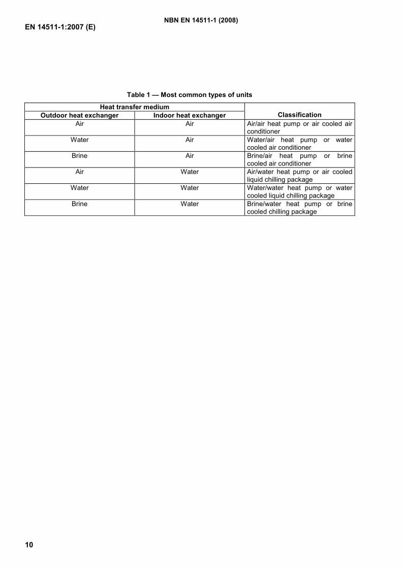
3 Classification
The units are denominated in such a way that the heat transfer medium for the outdoor heat exchanger is indicated first, followed by the heat transfer medium for the indoor heat exchanger (see Table 1).
NBN EN 14511-1 (2008)
EN 14511-1:2007 (E)
10
Table 1 — Most common types of units
Heat transfer medium Outdoor heat exchanger Indoor heat exchanger
Classification
Air Air Air/air heat pump or air cooled air conditioner
Water Air Water/air heat pump or water cooled air conditioner
Brine Air Brine/air heat pump or brine cooled air conditioner
Air Water Air/water heat pump or air cooled liquid chilling package
Water Water Water/water heat pump or water cooled liquid chilling package
Brine Water Brine/water heat pump or brine cooled chilling package
NBN EN 14511-1 (2008)
EN 14511-1:2007 (E)
11
Index
2
2.1 ......................................................................... 4, 5, 6 2.10 ............................................................................... 5 2.11 ............................................................................... 5 2.12 ............................................................................... 5 2.13 ............................................................................... 6 2.14 ............................................................................... 6 2.15 ............................................................................... 6 2.16 ............................................................................... 6 2.17 ............................................................................... 6 2.18 ............................................................................... 6 2.2 ............................................................................. 6, 7 2.20 ............................................................................... 6 2.21 ............................................................................... 6 2.23 ............................................................................... 6 2.24 ............................................................................... 6 2.25 ............................................................................... 7 2.26 ............................................................................... 7 2.27 ............................................................................... 7 2.28 ............................................................................... 7 2.3 ......................................................................... 5, 7, 8 2.30 ............................................................................... 7 2.31 ............................................................................... 7 2.33 ............................................................................... 7 2.34 ............................................................................... 8 2.35 ............................................................................... 8 2.36 ............................................................................... 8 2.37 ............................................................................... 8 2.38 ............................................................................... 8 2.4 ......................................................................... 5, 8, 9 2.40 ............................................................................... 8 2.41 ............................................................................... 8 2.42 ............................................................................... 8 2.43 ............................................................................... 8 2.44 ............................................................................... 8 2.45 ............................................................................... 9 2.46 ............................................................................... 9 2.47 ............................................................................... 9 2.48 ............................................................................... 9 2.5 ............................................................................. 5, 9 2.50 ............................................................................... 9 2.51 ............................................................................... 9 2.53 ............................................................................... 9 2.6 ................................................................................. 5 2.7 ................................................................................. 5 2.8 ................................................................................. 5 2.9 ................................................................................. 5
A
air conditioner ............................................. 4, 5, 6, 9, 10 application rating condition........................................... 8 application rating conditions ......................................... 8
B
basic multi-split system.................................................8 brine .................................................................... 4, 8, 10
C
close control air conditioner ..........................................5 coefficient of performance ............................................7 comfort air conditioner or heat pump............................5 control cabinet air conditioner.......................................5
D
defrost mode..................................................................8 defrost period ................................................................8
E
effective power input.................................................7, 9 energy efficiency ratio...................................................7 exhaust air .....................................................................6
G
glide...............................................................................8
H
heat pump................................................ 4, 5, 6, 8, 9, 10 heat recovery ..................................................... 5, 6, 7, 9 heat recovery capacity...................................................7 heat recovery efficiency ................................................9 heat recovery heat exchanger ....................................6, 7 heat recovery liquid chilling package........................5, 7 heat rejection capacity...................................................7 heat transfer medium......................................... 6, 7, 8, 9
I
indoor heat exchanger ....................................... 5, 6, 7, 9
L
latent cooling capacity.................................................6 liquid chilling package ........................................ 4, 5, 10
M
modular heat recovery multi-split system .....................9 modular multi-split system............................................9 multiple circuit multi-split system.................................9
O
operating cycle with defrost ..........................................8 operating range..........................................................7, 8 outdoor air .....................................................................6 outdoor heat exchanger ......................................... 6, 8, 9 outside air ......................................................................6
P
packaged unit ................................................................5
NBN EN 14511-1 (2008)
EN 14511-1:2007 (E)
12
R
rated capacity.................................................................9 rating condition..............................................................8 rating conditions ........................................................7, 9 recycled air ....................................................................6
S
sensible cooling capacity ...........................................6, 7 sensible heat ratio ..........................................................7 single split unit ..............................................................5 single-duct air conditioner .............................................5 sound power level ........................................................8 standard air ....................................................................9 standard rating condition ...........................................8, 9
system capacity............................................................. 9 system capacity ratio .................................................... 9 system reduced capacity ............................................... 9
T
temperature of saturated vapour at the discharge of the compressor................................................................ 8
temperature of the liquid refrigerant ............................. 8 the refrigerating cycle, like a heat pump .................. 5 total cooling capacity .............................................. 6, 7 total power input......................................................... 7
W
water loop ..................................................................... 6
NBN EN 14511-1 (2008)
EN 14511-1:2007 (E)
13
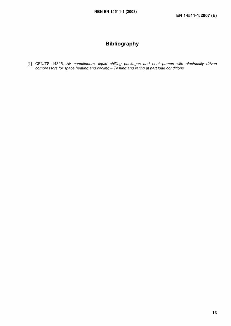
Bibliography
[1] CEN/TS 14825, Air conditioners, liquid chilling packages and heat pumps with electrically driven compressors for space heating and cooling – Testing and rating at part load conditions
NBN EN 14511-1 (2008)

GeregistreerdeBelgische norm
NBN EN 14511-2
Luchtbehandelingsapparatuur, koeleenheden met vloeistof enwarmtepompen met elektrisch aangedreven compressoren voorruimteverwarming en -koeling - Deel 2: BeproevingsomstandighedenClimatiseurs, groupes refroidisseurs de liquide et pompes à chaleur avec compresseur entraîné par moteurélectrique pour le chauffage et la réfrigération des locaux - Partie 2: Conditions d'essai
2e uitg., mei 2008
Normklasse: D 40
Air conditioners, liquid chilling packages and heat pumps with electrically driven compressors for spaceheating and cooling - Part 2: Test conditions
Prijsgroep: 14
Toelating tot publicatie: 29 januari 2008
Vervangt NBN EN 14511-2 (2004).
Deze Europese norm EN 14511-2:2008 heeft de status van een Belgische norm.
Deze Europese norm bestaat in drie officiële versies (Duits, Engels, Frans).
© NBN 2008
ICS: 23.120
Bureau voor Normalisatie Brabançonnelaan 29 B-1000 Brussel BelgiëTel: +32 2 738 01 12 - Fax: +32 2 733 42 64 - E-mail: [email protected] - NBN Online: www.nbn.beBank 000-3255621-10 IBAN BE41 0003 2556 2110 BIC BPOT BEB1 BTW: BE 0880.857.592
ICS: 23.120
norme belgeenregistrée
NBN EN 14511-2
Climatiseurs, groupes refroidisseurs de liquide et pompes à chaleuravec compresseur entraîné par moteur électrique pour le chauffage et laréfrigération des locaux - Partie 2: Conditions d'essaiLuchtbehandelingsapparatuur, koeleenheden met vloeistof en warmtepompen met elektrisch aangedrevencompressoren voor ruimteverwarming en -koeling - Deel 2: Beproevingsomstandigheden
2e éd., mai 2008
Indice de classement: D 40
Air conditioners, liquid chilling packages and heat pumps with electrically driven compressors for spaceheating and cooling - Part 2: Test conditions
Autorisation de publication: 29 janvier 2008
Remplace NBN EN 14511-2 (2004).
La présente norme européenne EN 14511-2:2008 a le statut d'une norme belge.
La présente norme européenne existe en trois versions officielles (allemand, anglais, français).
Prix: groupe 14© NBN 2008
Bureau de Normalisation - Avenue de la Brabançonne 29 - 1000 Bruxelles - BelgiqueTél: +32 2 738 01 12 - Fax: +32 2 733 42 64 - E-mail: [email protected] - NBN Online: www.nbn.beBanque 000-3255621-10 IBAN BE41 0003 2556 2110 BIC BPOT BEB1 TVA: BE 0880.857.592

EUROPEAN STANDARD
NORME EUROPÉENNE
EUROPÄISCHE NORM
EN 14511-2
November 2007
ICS 23.120 Supersedes EN 14511-2:2004
English Version
Air conditioners, liquid chilling packages and heat pumps withelectrically driven compressors for space heating and cooling -
Part 2: Test conditions
Climatiseurs, groupes refroidisseurs de liquide et pompes àchaleur avec compresseur entraîné par moteur électriquepour le chauffage et la réfrigération des locaux - Partie 2:
Conditions d'essai
Luftkonditionierer, Flüssigkeitskühlsätze undWärmepumpen mit elektrisch angetriebenen Verdichtern
für die Raumbeheizung und Kühlung - Teil 2:Prüfbedingungen
This European Standard was approved by CEN on 12 October 2007.
CEN members are bound to comply with the CEN/CENELEC Internal Regulations which stipulate the conditions for giving this EuropeanStandard the status of a national standard without any alteration. Up-to-date lists and bibliographical references concerning such nationalstandards may be obtained on application to the CEN Management Centre or to any CEN member.
This European Standard exists in three official versions (English, French, German). A version in any other language made by translationunder the responsibility of a CEN member into its own language and notified to the CEN Management Centre has the same status as theofficial versions.
CEN members are the national standards bodies of Austria, Belgium, Bulgaria, Cyprus, Czech Republic, Denmark, Estonia, Finland,France, Germany, Greece, Hungary, Iceland, Ireland, Italy, Latvia, Lithuania, Luxembourg, Malta, Netherlands, Norway, Poland, Portugal,Romania, Slovakia, Slovenia, Spain, Sweden, Switzerland and United Kingdom.
EUROPEAN COMMITTEE FOR STANDARDIZATIONC OM ITÉ EUR OP ÉEN DE NOR M ALIS AT IONEUROPÄISCHES KOMITEE FÜR NORMUNG
Management Centre: rue de Stassart, 36 B-1050 Brussels
© 2007 CEN All rights of exploitation in any form and by any means reservedworldwide for CEN national Members.
Ref. No. EN 14511-2:2007: E
NBN EN 14511-2 (2008)
EN 14511-2:2007 (E)
2
Contents Page
Foreword..............................................................................................................................................................3 1 Scope ......................................................................................................................................................4 2 Normative references ............................................................................................................................4 3 Terms and definitions ...........................................................................................................................4 4 Test conditions ......................................................................................................................................5 4.1 Environmental conditions and electrical power supply requirements ............................................5 4.2 Rating conditions...................................................................................................................................5 Annex A (normative) Energy labelling application .......................................................................................13 A.1 General..................................................................................................................................................13 A.2 Rating conditions.................................................................................................................................13 A.2.1 General..................................................................................................................................................13 A.2.2 Air-cooled air conditioners (air-to-air conditioners) ........................................................................13 A.2.3 Single-duct air conditioners ...............................................................................................................13 A.2.4 Water-cooled air conditioners (water-to-air conditioners) ..............................................................13 A.2.5 Double duct air conditioners ..............................................................................................................14 A.2.6 Other appliances..................................................................................................................................14 A.3 Test procedure .....................................................................................................................................14 A.4 Tolerances permitted on declared values.........................................................................................14 A.4.1 General..................................................................................................................................................14 A.4.2 First testing ..........................................................................................................................................14 A.4.3 Second testing .....................................................................................................................................15 Bibliography ......................................................................................................................................................16
NBN EN 14511-2 (2008)

EN 14511-2:2007 (E)
3
Foreword
This document (EN 14511-2:2007) has been prepared by Technical Committee CEN/TC 113 “Heat pumps and air conditioning units”, the secretariat of which is held by AENOR.
This European Standard shall be given the status of a national standard, either by publication of an identical text or by endorsement, at the latest by May 2008, and conflicting national standards shall be withdrawn at the latest by May 2008.
Attention is drawn to the possibility that some of the elements of this document may be the subject of patent rights. CEN shall not be held responsible for identifying any or all such patent rights.
This document supersedes EN 14511-2:2004.
EN 14511 comprises the following parts under the general title "Air conditioners, liquid chilling packages and heat pumps with electrically driven compressors for space heating and cooling“:
- Part 1: Terms and definitions
- Part 2: Test conditions
- Part 3: Test methods
- Part 4: Requirements
According to the CEN/CENELEC Internal Regulations, the national standards organizations of the following countries are bound to implement this European Standard: Austria, Belgium, Bulgaria, Cyprus, Czech Republic, Denmark, Estonia, Finland, France, Germany, Greece, Hungary, Iceland, Ireland, Italy, Latvia, Lithuania, Luxembourg, Malta, Netherlands, Norway, Poland, Portugal, Romania, Slovakia, Slovenia, Spain, Sweden, Switzerland and the United Kingdom.
NBN EN 14511-2 (2008)
EN 14511-2:2007 (E)
4
1 Scope
This part of EN 14511 specifies the test conditions for the rating of air and water cooled air conditioners, liquid chilling packages, air-to-air, water-to-air, air-to-water and water-to-water heat pumps with electrically driven compressors when used for space heating and/or cooling. It also specifies test conditions for heat recovery operation of multisplit systems.
This European Standard applies to factory-made units that can be ducted.
This standard applies to factory-made liquid chilling packages with integral condensers or for use with remote condensers.
This standard applies to factory-made units of either fixed capacity or variable capacity by any means.
Packaged units, single split and multisplit systems are covered by this standard. Single duct and double duct units are covered by the standard.
In the case of units consisting of several parts, the standard applies only to those designed and supplied as a complete package, except for liquid chilling packages with remote condenser.
This standard is primarily intended for water and brine chilling packages but can be used for other liquid subject to agreement.
This standard applies to air-to-air air conditioners which evaporate the condensate on the condenser side.
The units having their condenser cooled by air and by the evaporation of external additional water are not covered by this standard.
This standard does not apply to units using transcritical cycles, e.g. with CO2 as refrigerant.
Installations used for heating and/or cooling of industrial processes are not within the scope of this standard.
NOTE Part load testing of units is dealt with in CEN/TS 14825.
2 Normative references
The following referenced documents are indispensable for the application of this document. For dated references, only the edition cited applies. For undated references, the latest edition of the referenced document (including any amendments) applies.
EN 14511-1:2007, Air conditioners, liquid chilling packages and heat pumps with electrically driven compressors for space heating and cooling - Part 1: Terms and definitions
EN 14511-3:2007, Air conditioners, liquid chilling packages and heat pumps with electrically driven compressors for space heating and cooling - Part 3: Test methods
EN 14511-4:2007, Air conditioners, liquid chilling packages and heat pumps with electrically driven compressors for space heating and cooling - Part 4: Requirements
3 Terms and definitions
For the purposes of this document, the terms and definitions given in EN 14511-1:2007 apply.
NBN EN 14511-2 (2008)
EN 14511-2:2007 (E)
5
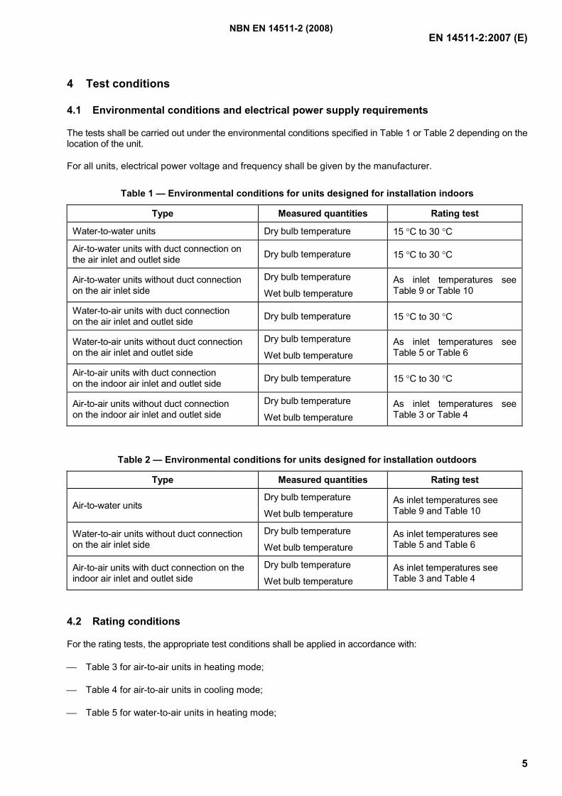
4 Test conditions
4.1 Environmental conditions and electrical power supply requirements
The tests shall be carried out under the environmental conditions specified in Table 1 or Table 2 depending on the location of the unit.
For all units, electrical power voltage and frequency shall be given by the manufacturer.
Table 1 — Environmental conditions for units designed for installation indoors
Type Measured quantities Rating test
Water-to-water units Dry bulb temperature 15 °C to 30 °C
Air-to-water units with duct connection on the air inlet and outlet side Dry bulb temperature 15 °C to 30 °C
Air-to-water units without duct connection on the air inlet side
Dry bulb temperature
Wet bulb temperature As inlet temperatures see Table 9 or Table 10
Water-to-air units with duct connection on the air inlet and outlet side Dry bulb temperature 15 °C to 30 °C
Water-to-air units without duct connection on the air inlet and outlet side
Dry bulb temperature
Wet bulb temperature As inlet temperatures see Table 5 or Table 6
Air-to-air units with duct connection on the indoor air inlet and outlet side Dry bulb temperature 15 °C to 30 °C
Air-to-air units without duct connection on the indoor air inlet and outlet side
Dry bulb temperature
Wet bulb temperature As inlet temperatures see Table 3 or Table 4
Table 2 — Environmental conditions for units designed for installation outdoors
Type Measured quantities Rating test
Air-to-water units Dry bulb temperature
Wet bulb temperature As inlet temperatures see Table 9 and Table 10
Water-to-air units without duct connection on the air inlet side
Dry bulb temperature
Wet bulb temperature As inlet temperatures see Table 5 and Table 6
Air-to-air units with duct connection on the indoor air inlet and outlet side
Dry bulb temperature
Wet bulb temperature As inlet temperatures see Table 3 and Table 4
4.2 Rating conditions
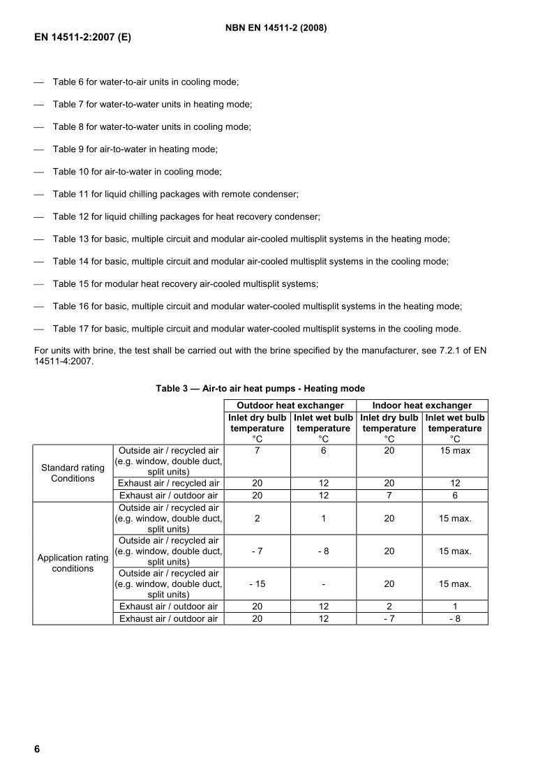
For the rating tests, the appropriate test conditions shall be applied in accordance with:
Table 3 for air-to-air units in heating mode;
Table 4 for air-to-air units in cooling mode;
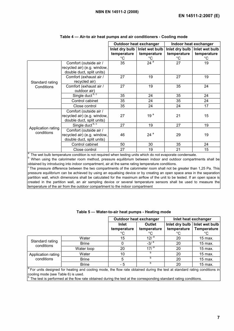
Table 5 for water-to-air units in heating mode;
NBN EN 14511-2 (2008)
EN 14511-2:2007 (E)
6
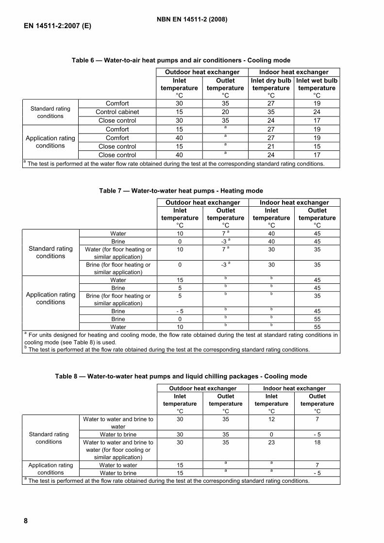
Table 6 for water-to-air units in cooling mode;
Table 7 for water-to-water units in heating mode;
Table 8 for water-to-water units in cooling mode;
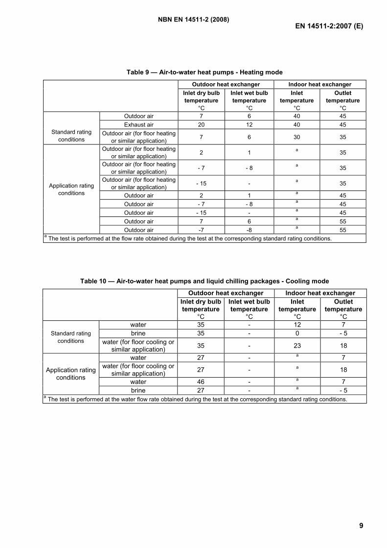
Table 9 for air-to-water in heating mode;
Table 10 for air-to-water in cooling mode;
Table 11 for liquid chilling packages with remote condenser;
Table 12 for liquid chilling packages for heat recovery condenser;
Table 13 for basic, multiple circuit and modular air-cooled multisplit systems in the heating mode;
Table 14 for basic, multiple circuit and modular air-cooled multisplit systems in the cooling mode;
Table 15 for modular heat recovery air-cooled multisplit systems;
Table 16 for basic, multiple circuit and modular water-cooled multisplit systems in the heating mode;
Table 17 for basic, multiple circuit and modular water-cooled multisplit systems in the cooling mode.
For units with brine, the test shall be carried out with the brine specified by the manufacturer, see 7.2.1 of EN 14511-4:2007.
Table 3 — Air-to air heat pumps - Heating mode
Outdoor heat exchanger Indoor heat exchanger Inlet dry bulb temperature
°C
Inlet wet bulb temperature
°C
Inlet dry bulb temperature
°C
Inlet wet bulb temperature
°C Outside air / recycled air
(e.g. window, double duct, split units)
7 6 20 15 max
Exhaust air / recycled air 20 12 20 12 Standard rating
Conditions
Exhaust air / outdoor air 20 12 7 6 Outside air / recycled air
(e.g. window, double duct, split units)
2 1 20 15 max.
Outside air / recycled air (e.g. window, double duct,
split units) - 7 - 8 20 15 max.
Outside air / recycled air (e.g. window, double duct,
split units) - 15 - 20 15 max.
Exhaust air / outdoor air 20 12 2 1
Application rating conditions
Exhaust air / outdoor air 20 12 - 7 - 8
NBN EN 14511-2 (2008)
EN 14511-2:2007 (E)
7
Table 4 — Air-to air heat pumps and air conditioners - Cooling mode
Outdoor heat exchanger Indoor heat exchanger Inlet dry bulb temperature
°C
Inlet wet bulb temperature
°C
Inlet dry bulb temperature
°C
Inlet wet bulb temperature
°C Comfort (outside air /
recycled air) (e.g. window, double duct, split units)
35 24 a 27 19
Comfort (exhaust air / recycled air)
27 19 27 19
Comfort (exhaust air / outdoor air)
27 19 35 24
Single duct b, c 35 24 35 24 Control cabinet 35 24 35 24
Standard rating Conditions
Close control 35 24 24 17 Comfort (outside air /
recycled air) (e.g. window, double duct, split units)
27 19 a 21 15
Single duct b, c 27 19 27 19 Comfort (outside air /
recycled air) (e.g. window, double duct, split units)
46 24 a 29 19
Control cabinet 50 30 35 24
Application rating conditions
Close control 27 19 21 15 a The wet bulb temperature condition is not required when testing units which do not evaporate condensate. b When using the calorimeter room method, pressure equilibrium between indoor and outdoor compartments shall be obtained by introducing into indoor compartment, air at the same rating temperature conditions. c The pressure difference between the two compartments of the calorimeter room shall not be greater than 1,25 Pa. This pressure equilibrium can be achieved by using an equalising device or by creating an open space area in the separation partition wall, which dimensions shall be calculated for the maximum airflow of the unit to be tested. If an open space is created in the partition wall, an air sampling device or several temperature sensors shall be used to measure the temperature of the air from the outdoor compartment to the indoor compartment
Table 5 — Water-to-air heat pumps - Heating mode
Outdoor heat exchanger Inlet heat exchanger Inlet
temperature °C
Outlet temperature
°C
Inlet dry bulb temperature
°C
Inlet wet bulb Temperature
°C Water 15 12/ a 20 15 max. Brine 0 -3/ a 20 15 max. Standard rating
conditions Water loop 20 17/ a 20 15 max.
Water 10 b 20 15 max. Brine 5 b 20 15 max.
Application rating conditions
Brine - 5 b 20 15 max. a For units designed for heating and cooling mode, the flow rate obtained during the test at standard rating conditions in cooling mode (see Table 6) is used. b The test is performed at the flow rate obtained during the test at the corresponding standard rating conditions.
NBN EN 14511-2 (2008)
EN 14511-2:2007 (E)
8
Table 6 — Water-to-air heat pumps and air conditioners - Cooling mode
Outdoor heat exchanger Indoor heat exchanger Inlet
temperature°C
Outlet temperature
°C
Inlet dry bulb temperature
°C
Inlet wet bulb temperature
°C Comfort 30 35 27 19
Control cabinet 15 20 35 24 Standard rating conditions
Close control 30 35 24 17 Comfort 15 a 27 19 Comfort 40 a 27 19
Close control 15 a 21 15 Application rating
conditions Close control 40 a 24 17
a The test is performed at the water flow rate obtained during the test at the corresponding standard rating conditions.
Table 7 — Water-to-water heat pumps - Heating mode
Outdoor heat exchanger Indoor heat exchanger Inlet
temperature°C
Outlet temperature
°C
Inlet temperature
°C
Outlet temperature
°C Water 10 7 a 40 45 Brine 0 -3 a 40 45
Water (for floor heating or similar application)
10 7 a 30 35 Standard rating conditions
Brine (for floor heating or similar application)
0 -3 a 30 35
Water 15 b b 45 Brine 5 b b 45
Brine (for floor heating or similar application)
5 b b 35
Brine - 5 b b 45 Brine 0 b b 55
Application rating conditions
Water 10 b b 55 a For units designed for heating and cooling mode, the flow rate obtained during the test at standard rating conditions in cooling mode (see Table 8) is used. b The test is performed at the flow rate obtained during the test at the corresponding standard rating conditions.
Table 8 — Water-to-water heat pumps and liquid chilling packages - Cooling mode
Outdoor heat exchanger Indoor heat exchanger Inlet
temperature °C
Outlet temperature
°C
Inlet temperature
°C
Outlet temperature
°C Water to water and brine to
water 30 35 12 7
Water to brine 30 35 0 - 5 Standard rating conditions Water to water and brine to
water (for floor cooling or similar application)
30 35 23 18
Water to water 15 a a 7 Application rating conditions Water to brine 15 a a - 5
a The test is performed at the flow rate obtained during the test at the corresponding standard rating conditions.
NBN EN 14511-2 (2008)
EN 14511-2:2007 (E)
9
Table 9 — Air-to-water heat pumps - Heating mode
Outdoor heat exchanger Indoor heat exchanger Inlet dry bulb temperature
°C
Inlet wet bulb temperature
°C
Inlet temperature
°C
Outlet temperature
°C Outdoor air 7 6 40 45 Exhaust air 20 12 40 45
Standard rating conditions
Outdoor air (for floor heating or similar application) 7 6 30 35
Outdoor air (for floor heating or similar application) 2 1 a 35
Outdoor air (for floor heating or similar application) - 7 - 8 a 35
Outdoor air (for floor heating or similar application) - 15 - a 35
Outdoor air 2 1 a 45 Outdoor air - 7 - 8 a 45 Outdoor air - 15 - a 45 Outdoor air 7 6 a 55
Application rating conditions
Outdoor air -7 -8 a 55 a The test is performed at the flow rate obtained during the test at the corresponding standard rating conditions.
Table 10 — Air-to-water heat pumps and liquid chilling packages - Cooling mode
Outdoor heat exchanger Indoor heat exchanger Inlet dry bulb temperature
°C
Inlet wet bulb temperature
°C
Inlet temperature
°C
Outlet temperature
°C water 35 - 12 7 brine 35 - 0 - 5 Standard rating
conditions water (for floor cooling or similar application) 35 - 23 18
water 27 - a 7 water (for floor cooling or
similar application) 27 - a 18
water 46 - a 7
Application rating conditions
brine 27 - a - 5 a The test is performed at the water flow rate obtained during the test at the corresponding standard rating conditions.
NBN EN 14511-2 (2008)
EN 14511-2:2007 (E)
10
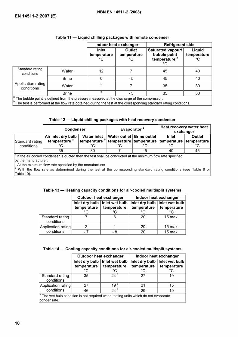
Table 11 — Liquid chilling packages with remote condenser
Indoor heat exchanger Refrigerant side Inlet
temperature°C
Outlet temperature
°C
Saturated vapour/ bubble point temperature a
°C
Liquid temperature
°C
Standard rating conditions Water 12 7 45 40
Brine 0 - 5 45 40 Application rating
conditions Water b 7 35 30
Brine b - 5 35 30 a The bubble point is defined from the pressure measured at the discharge of the compressor. b The test is performed at the flow rate obtained during the test at the corresponding standard rating conditions.
Table 12 — Liquid chilling packages with heat recovery condenser
Condenser Evaporator c Heat recovery water heat exchanger
Air inlet dry bulb temperature a
°C
Water inlet temperature b
°C
Water outlet temperature
°C
Brine outlet temperature
°C
Inlet temperature
°C
Outlet temperature
°C Standard rating
conditions 35 30 7 -5 40 45
a If the air cooled condenser is ducted then the test shall be conducted at the minimum flow rate specified by the manufacturer. b At the minimum flow rate specified by the manufacturer. c With the flow rate as determined during the test at the corresponding standard rating conditions (see Table 8 or Table 10).
Table 13 — Heating capacity conditions for air-cooled multisplit systems
Outdoor heat exchanger Indoor heat exchanger Inlet dry bulb temperature
°C
Inlet wet bulb temperature
°C
Inlet dry bulb temperature
°C
Inlet wet bulb temperature
°C Standard rating
conditions 7 6 20 15 max.
2 1 20 15 max. Application rating conditions - 7 - 8 20 15 max.
Table 14 — Cooling capacity conditions for air-cooled multisplit systems
Outdoor heat exchanger Indoor heat exchanger Inlet dry bulb temperature
°C
Inlet wet bulb temperature
°C
Inlet dry bulb temperature
°C
Inlet wet bulb temperature
°C Standard rating
conditions 35 24 a 27 19
27 19 a 21 15 Application rating conditions 46 24 a 29 19
a The wet bulb condition is not required when testing units which do not evaporate condensate.
NBN EN 14511-2 (2008)
EN 14511-2:2007 (E)
11
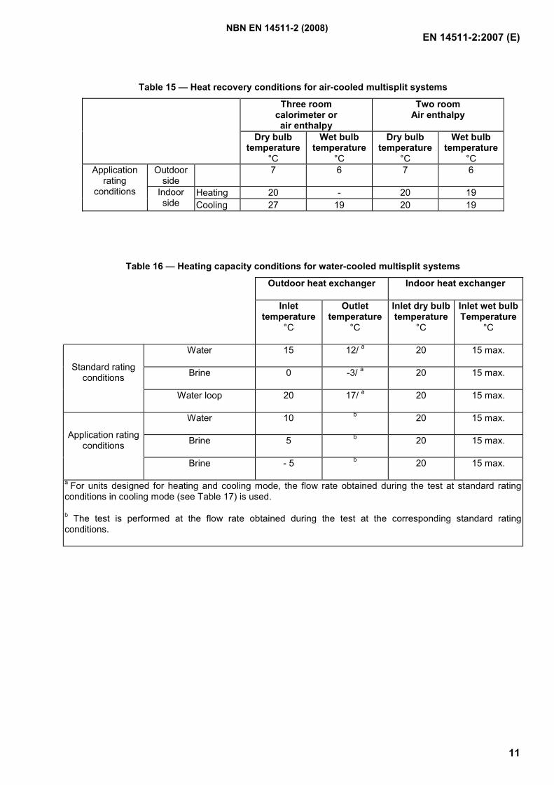
Table 15 — Heat recovery conditions for air-cooled multisplit systems
Three room calorimeter or air enthalpy
Two room Air enthalpy
Dry bulb temperature
°C
Wet bulb temperature
°C
Dry bulb temperature
°C
Wet bulb temperature
°C Outdoor
side 7 6 7 6
Heating 20 - 20 19
Application rating
conditions Indoor side Cooling 27 19 20 19
Table 16 — Heating capacity conditions for water-cooled multisplit systems Outdoor heat exchanger Indoor heat exchanger
Inlet temperature
°C
Outlet temperature
°C
Inlet dry bulb temperature
°C
Inlet wet bulb Temperature
°C
Water 15 12/ a 20 15 max.
Brine 0 -3/ a 20 15 max. Standard rating conditions
Water loop 20 17/ a 20 15 max.
Water 10 b 20 15 max.
Brine 5 b 20 15 max. Application rating conditions
Brine - 5 b 20 15 max.
a For units designed for heating and cooling mode, the flow rate obtained during the test at standard rating conditions in cooling mode (see Table 17) is used.
b The test is performed at the flow rate obtained during the test at the corresponding standard rating conditions.
NBN EN 14511-2 (2008)
EN 14511-2:2007 (E)
12
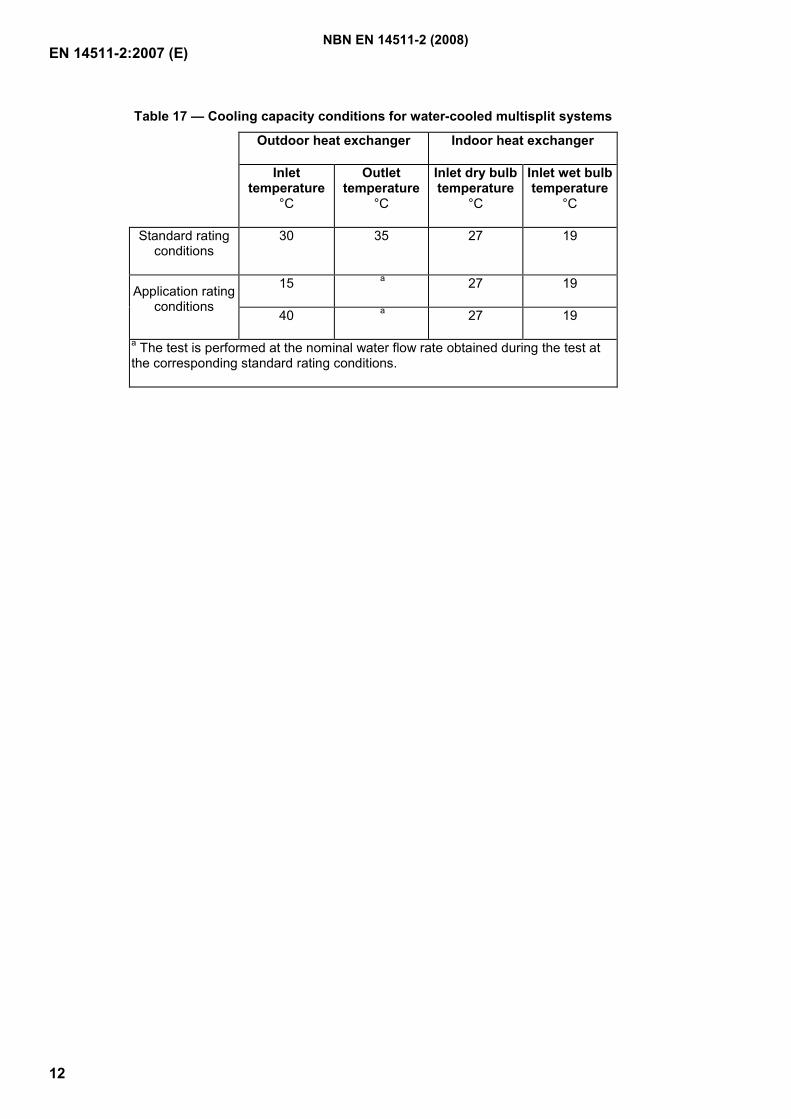
Table 17 — Cooling capacity conditions for water-cooled multisplit systems Outdoor heat exchanger Indoor heat exchanger
Inlet temperature
°C
Outlet temperature
°C
Inlet dry bulb temperature
°C
Inlet wet bulb temperature
°C
Standard rating conditions
30 35 27 19
15 a 27 19 Application rating conditions
40 a 27 19
a The test is performed at the nominal water flow rate obtained during the test at the corresponding standard rating conditions.
NBN EN 14511-2 (2008)
EN 14511-2:2007 (E)
13
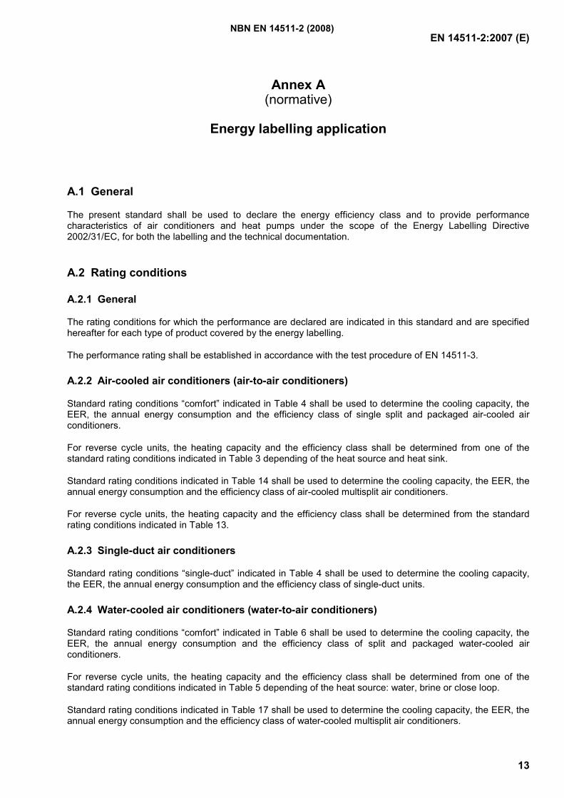
Annex A (normative)
Energy labelling application
A.1 General
The present standard shall be used to declare the energy efficiency class and to provide performance characteristics of air conditioners and heat pumps under the scope of the Energy Labelling Directive 2002/31/EC, for both the labelling and the technical documentation.
A.2 Rating conditions
A.2.1 General
The rating conditions for which the performance are declared are indicated in this standard and are specified hereafter for each type of product covered by the energy labelling.
The performance rating shall be established in accordance with the test procedure of EN 14511-3.
A.2.2 Air-cooled air conditioners (air-to-air conditioners)
Standard rating conditions “comfort” indicated in Table 4 shall be used to determine the cooling capacity, the EER, the annual energy consumption and the efficiency class of single split and packaged air-cooled air conditioners.
For reverse cycle units, the heating capacity and the efficiency class shall be determined from one of the standard rating conditions indicated in Table 3 depending of the heat source and heat sink.
Standard rating conditions indicated in Table 14 shall be used to determine the cooling capacity, the EER, the annual energy consumption and the efficiency class of air-cooled multisplit air conditioners.
For reverse cycle units, the heating capacity and the efficiency class shall be determined from the standard rating conditions indicated in Table 13.
A.2.3 Single-duct air conditioners
Standard rating conditions “single-duct” indicated in Table 4 shall be used to determine the cooling capacity, the EER, the annual energy consumption and the efficiency class of single-duct units.
A.2.4 Water-cooled air conditioners (water-to-air conditioners)
Standard rating conditions “comfort” indicated in Table 6 shall be used to determine the cooling capacity, the EER, the annual energy consumption and the efficiency class of split and packaged water-cooled air conditioners.
For reverse cycle units, the heating capacity and the efficiency class shall be determined from one of the standard rating conditions indicated in Table 5 depending of the heat source: water, brine or close loop.
Standard rating conditions indicated in Table 17 shall be used to determine the cooling capacity, the EER, the annual energy consumption and the efficiency class of water-cooled multisplit air conditioners.
NBN EN 14511-2 (2008)
EN 14511-2:2007 (E)
14
For reverse cycle units, the heating capacity and the efficiency class shall be determined from the standard rating conditions indicated in Table 16.
A.2.5 Double duct air conditioners
Standard rating conditions “comfort” (outside air / recycled air) indicated in Table 4 shall be used to determine the cooling capacity, the EER, the annual energy consumption and the efficiency class of double duct air conditioners.
For reverse cycle units, the heating capacity and the efficiency class shall be determined from the standard rating conditions "Outside air / recycled air" indicated in Table 3.
A.2.6 Other appliances
Single-duct units operating in the heating mode to which Table 3.3 of Annex IV of Directive 2002/31/EC refers are not covered by EN 14511.
A.3 Test procedure
When the present standard is used for the energy labelling of air conditioners and heat pumps below 12 kW, the cooling / heating capacities, power input and EER/COP as well as the energy efficiency class of a product shall be determined by using exclusively the calorimeter room method.
For ducted units, the settings of the air flow rate and external static pressure shall be made prior to the cooling / heating capacity tests, according to EN 14511-3:2007, 4.4.1. Once determined, the static pressure shall be set, with dry coil, by adjusting to the air discharge area of the unit, a length of duct equipped with a damper which position shall not be changed during the capacity tests.
The length of duct and the distance of the damper from the discharge section of the unit shall conform to the requirements of EN 14511-3:2007, B.2.1.
A.4 Tolerances permitted on declared values
A.4.1 General
The following requirements apply to the declared values.
The requirements for the uncertainties of measurement of 4.3 of EN 14511-3:2007 shall be respected.
A.4.2 First testing
The performance published data shall be accepted as valid when a sample of a model, tested in accordance with the present standard, shall meet the following criteria for cooling and heating mode as applicable:
Tested cooling and heating capacity ≥ 0,88 X declared capacity
Tested EER ≥ 0,85 X declared EER
Tested COP ≥ 0,85 X declared COP
NBN EN 14511-2 (2008)

EN 14511-2:2007 (E)
15
A.4.3 Second testing
If the result of test on capacity and/or EER/COP carried out on the first appliance is not in compliance with the requirements given in A.4.2, a second test shall be carried out on one other appliance. This second test shall meet the following criteria for cooling and heating mode as applicable:
Tested cooling and heating capacity ≥ 0,88 X declared capacity
Tested EER ≥ 0,85 X declared EER
Tested COP ≥ 0,85 X declared COP
NBN EN 14511-2 (2008)
EN 14511-2:2007 (E)
16
Bibliography
[1] CEN/TS 14825, Air conditioners, liquid chilling packages and heat pumps with electrically driven compressors for space heating and cooling – Testing and rating at part load conditions
[2] Commission Directive 2002/31/EC – Implementation of Council Directive 92/75/EEC with regard to energy labelling of household air-conditioners
NBN EN 14511-2 (2008)

GeregistreerdeBelgische norm
NBN EN 14511-3
Luchtbehandelingsapparatuur, koeleenheden met vloeistof enwarmtepompen met elektrisch aangedreven compressoren voorruimteverwarming en voor koeling - Deel 3: BeproevingsmethodenClimatiseurs, groupes refroidisseurs de liquide et pompes à chaleur avec compresseur entraîné par moteurélectrique pour le chauffage et la réfrigération des locaux - Partie 3 : Méthodes d'essai
2e uitg., mei 2008
Normklasse: D 40
Air conditioners, liquid chilling packages and heat pumps with electrically driven compressors for spaceheating and cooling - Part 3: Test methods
Prijsgroep: 20
Toelating tot publicatie: 29 januari 2008
Vervangt NBN EN 14511-3 (2004).
Deze Europese norm EN 14511-3:2008 heeft de status van een Belgische norm.
Deze Europese norm bestaat in drie officiële versies (Duits, Engels, Frans).
© NBN 2008
ICS: 23.120
Bureau voor Normalisatie Brabançonnelaan 29 B-1000 Brussel BelgiëTel: +32 2 738 01 12 - Fax: +32 2 733 42 64 - E-mail: [email protected] - NBN Online: www.nbn.beBank 000-3255621-10 IBAN BE41 0003 2556 2110 BIC BPOT BEB1 BTW: BE 0880.857.592
ICS: 23.120
norme belgeenregistrée
NBN EN 14511-3
Climatiseurs, groupes refroidisseurs de liquide et pompes à chaleuravec compresseur entraîné par moteur électrique pour le chauffage et laréfrigération des locaux - Partie 3 : Méthodes d'essaiLuchtbehandelingsapparatuur, koeleenheden met vloeistof en warmtepompen met elektrisch aangedrevencompressoren voor ruimteverwarming en voor koeling - Deel 3: Beproevingsmethoden
2e éd., mai 2008
Indice de classement: D 40
Air conditioners, liquid chilling packages and heat pumps with electrically driven compressors for spaceheating and cooling - Part 3: Test methods
Autorisation de publication: 29 janvier 2008
Remplace NBN EN 14511-3 (2004).
La présente norme européenne EN 14511-3:2008 a le statut d'une norme belge.
La présente norme européenne existe en trois versions officielles (allemand, anglais, français).
Prix: groupe 20© NBN 2008
Bureau de Normalisation - Avenue de la Brabançonne 29 - 1000 Bruxelles - BelgiqueTél: +32 2 738 01 12 - Fax: +32 2 733 42 64 - E-mail: [email protected] - NBN Online: www.nbn.beBanque 000-3255621-10 IBAN BE41 0003 2556 2110 BIC BPOT BEB1 TVA: BE 0880.857.592

EUROPEAN STANDARD
NORME EUROPÉENNE
EUROPÄISCHE NORM
EN 14511-3
November 2007
ICS 23.120 Supersedes EN 14511-3:2004
English Version
Air conditioners, liquid chilling packages and heat pumps withelectrically driven compressors for space heating and cooling -
Part 3: Test methods
Climatiseurs, groupes refroidisseurs de liquide et pompes àchaleur avec compresseur entraîné par moteur électriquepour le chauffage et la réfrigération des locaux - Partie 3 :
Méthodes d'essai
Luftkonditionierer, Flüssigkeitskühlsätze undWärmepumpen mit elektrisch angetriebenen Verdichtern
für die Raumbeheizung und Kühlung - Teil 3: Prüfverfahren
This European Standard was approved by CEN on 13 October 2007.
CEN members are bound to comply with the CEN/CENELEC Internal Regulations which stipulate the conditions for giving this EuropeanStandard the status of a national standard without any alteration. Up-to-date lists and bibliographical references concerning such nationalstandards may be obtained on application to the CEN Management Centre or to any CEN member.
This European Standard exists in three official versions (English, French, German). A version in any other language made by translationunder the responsibility of a CEN member into its own language and notified to the CEN Management Centre has the same status as theofficial versions.
CEN members are the national standards bodies of Austria, Belgium, Bulgaria, Cyprus, Czech Republic, Denmark, Estonia, Finland,France, Germany, Greece, Hungary, Iceland, Ireland, Italy, Latvia, Lithuania, Luxembourg, Malta, Netherlands, Norway, Poland, Portugal,Romania, Slovakia, Slovenia, Spain, Sweden, Switzerland and United Kingdom.
EUROPEAN COMMITTEE FOR STANDARDIZATIONC OM ITÉ EUR OP ÉEN DE NOR M ALIS AT IONEUROPÄISCHES KOMITEE FÜR NORMUNG
Management Centre: rue de Stassart, 36 B-1050 Brussels
© 2007 CEN All rights of exploitation in any form and by any means reservedworldwide for CEN national Members.
Ref. No. EN 14511-3:2007: E
NBN EN 14511-3 (2008)
EN 14511-3:2007 (E)
2
Contents Page
Foreword..............................................................................................................................................................4 1 Scope ......................................................................................................................................................5 2 Normative references ............................................................................................................................5 3 Terms and definitions ...........................................................................................................................5 4 Rating capacity test ...............................................................................................................................6 4.1 Basic principles .....................................................................................................................................6 4.1.1 Heating capacity ....................................................................................................................................6 4.1.2 Cooling capacity ....................................................................................................................................6 4.1.3 Heat recovery capacity..........................................................................................................................7 4.1.4 Power input of fans for units without duct connection .....................................................................7 4.1.5 Power input of fans for units with duct connection...........................................................................8 4.1.6 Power input of liquid pumps ................................................................................................................8 4.1.7 Units for use with remote condenser ..................................................................................................9 4.2 Test apparatus .......................................................................................................................................9 4.2.1 Arrangement of the test apparatus ......................................................................................................9 4.2.2 Installation and connection of the test object ..................................................................................10 4.3 Uncertainties of measurement ...........................................................................................................11 4.4 Test procedure .....................................................................................................................................12 4.4.1 General..................................................................................................................................................12 4.4.2 Output measurement for water-to-water and water-to-air units .....................................................14 4.4.3 Output measurement for cooling capacity of air-to-water and air-to-air units .............................14 4.4.4 Output measurement for heating capacity of air-to-water and air-to-air units .............................15 4.5 Test results...........................................................................................................................................17 4.5.1 Data to be recorded .............................................................................................................................17 4.5.2 Cooling capacity and heat recovery capacity calculation...............................................................19 4.5.3 Heating capacity calculation ..............................................................................................................20 4.5.4 Effective power input calculation.......................................................................................................20 5 Heat recovery test for air-cooled multisplit systems.......................................................................20 5.1 Test installation....................................................................................................................................20 5.1.1 General..................................................................................................................................................20 5.1.2 Three-room calorimeter method ........................................................................................................21 5.1.3 Three-room air-enthalpy method .......................................................................................................21 5.1.4 Two-room air-enthalpy method..........................................................................................................21 5.2 Test procedure .....................................................................................................................................21 5.3 Test results...........................................................................................................................................21 6 Test report ............................................................................................................................................21 6.1 General information.............................................................................................................................21 6.2 Additional information ........................................................................................................................22 6.3 Rating test results................................................................................................................................22 Annex A (informative) Calorimeter test method............................................................................................23 Annex B (informative) Indoor air enthalpy test method ...............................................................................31 Annex C (informative) Heating capacity tests - Flow chart and examples of different test
sequences ............................................................................................................................................33 Annex D (informative) Conformance criteria.................................................................................................37 Annex E (informative) Symbols used in annexes .........................................................................................38 Annex F (informative) Test at system reduced capacity..............................................................................40
NBN EN 14511-3 (2008)

EN 14511-3:2007 (E)
3
Annex G (informative) Individual unit tests...................................................................................................41 Bibliography......................................................................................................................................................43
NBN EN 14511-3 (2008)
EN 14511-3:2007 (E)
4
Foreword
This document (EN 14511-3:2007) has been prepared by Technical Committee CEN/TC 113 “Heat pumps and air conditioning units”, the secretariat of which is held by AENOR.
This European Standard shall be given the status of a national standard, either by publication of an identical text or by endorsement, at the latest by May 2008, and conflicting national standards shall be withdrawn at the latest by May 2008.
Attention is drawn to the possibility that some of the elements of this document may be the subject of patent rights. CEN shall not be held responsible for identifying any or all such patent rights.
This document supersedes EN 14511-3:2004.
EN 14511 comprises the following parts under the general title "Air conditioners, liquid chilling packages and heat pumps with electrically driven compressors for space heating and cooling“:
- Part 1: Terms and definitions
- Part 2: Test conditions
- Part 3: Test methods
- Part 4: Requirements
According to the CEN/CENELEC Internal Regulations, the national standards organizations of the following countries are bound to implement this European Standard: Austria, Belgium, Bulgaria, Cyprus, Czech Republic, Denmark, Estonia, Finland, France, Germany, Greece, Hungary, Iceland, Ireland, Italy, Latvia, Lithuania, Luxembourg, Malta, Netherlands, Norway, Poland, Portugal, Romania, Slovakia, Slovenia, Spain, Sweden, Switzerland and the United Kingdom.
NBN EN 14511-3 (2008)
EN 14511-3:2007 (E)
5
1 Scope
This part of EN 14511 specifies the test methods for the rating and performance of air and water-cooled air conditioners, liquid chilling packages, air-to-air, water-to-air, air-to-water and water-to-water heat pumps with electrically driven compressors when used for space heating and cooling.
It also specifies the method of testing and reporting for heat recovery capacities, system reduced capacities and the capacity of individual indoor units of multisplit systems, where applicable.
This European Standard applies to factory-made units that can be ducted.
This standard applies to factory-made liquid chilling packages with integral condensers or for use with remote condensers.
This standard applies to factory-made units of either fixed capacity or variable capacity by any means.
Packaged units, single split and multisplit systems are covered by this standard. Single duct and double duct units are covered by the standard.
In the case of units consisting of several parts, the standard applies only to those designed and supplied as a complete package, except for liquid chilling packages with remote condenser.
This standard is primarily intended for water and brine chilling packages but can be used for other liquid subject to agreement.
This standard applies to air-to-air air conditioners which evaporate the condensate on the condenser side.
The units having their condenser cooled by air and by the evaporation of external additional water are not covered by this standard.
This standard does not apply to units using transcritical cycles, e.g. with CO2 as refrigerant.
Installations used for heating and/or cooling of industrial processes are not within the scope of this standard.
NOTE 1 Part load testing of units is dealt with in CEN/TS 14825.
NOTE 2 All the symbols given in this text should be used regardless of the language used.
2 Normative references
The following referenced documents are indispensable for the application of this document. For dated references, only the edition cited applies. For undated references, the latest edition of the referenced document (including any amendments) applies.
EN 14511-1:2007, Air conditioners, liquid chilling packages and heat pumps with electrically driven compressors for space heating and cooling – Part 1: Terms and definitions
EN 14511-2:2007, Air conditioners, liquid chilling packages and heat pumps with electrically driven compressors for space heating and cooling – Part 2: Test conditions
3 Terms and definitions
For the purposes of this document, the terms and definitions given in EN 14511-1:2007 apply.
NBN EN 14511-3 (2008)
EN 14511-3:2007 (E)
6
4 Rating capacity test
4.1 Basic principles
4.1.1 Heating capacity
The heating capacity of air conditioners and of air-to-air or water-to-air heat pumps shall be determined by measurements in a calorimeter room or by the air enthalpy method which are described in Annex A and Annex B respectively.
The heating capacity of air-to-water, water-to-water heat pumps and liquid chilling packages shall be determined in accordance with the direct method at the water or brine heat exchanger, by determination of the volume flow of the heat transfer medium, and the inlet and outlet temperatures, taking into consideration the specific heat capacity and density of the heat transfer medium.
For steady state operation, the heating capacity shall be determined using the following formula:
tcqP pH ∆××= ρ (1)
where:
PH is the heat capacity, in Watts;
q is the volume flow rate, in cubic metres per second;
ρ is the density, in kilograms per cubic metre;
cp is the specific heat at constant pressure, in joules per kilogram and kelvin;
∆t is the difference between inlet and outlet temperatures, in kelvin.
For the heating capacity calculation in transient operation, refer to 4.5.3.2.
The heating capacity shall be corrected for the heat from the fan or pump:
− if the fan or pump at the indoor heat exchanger is an integral part of the unit, the same power (calculated in 4.1.5.1 or 4.1.6.1) which is excluded from the total power input shall be also subtracted from the heating capacity;
− If the fan or pump at the indoor heat exchanger is not an integral part of the unit, the same power (calculated in 4.1.5.2 or 4.1.6.2) which is included in the effective power input shall be also added to the heating capacity.
4.1.2 Cooling capacity
The cooling capacity of air conditioners and of air-to-air or water-to-air heat pumps shall be determined by measurements in a calorimeter room or by the air enthalpy method which are described in Annex A and Annex B respectively.
The cooling capacity of air-to-water, water-to-water heat pumps and liquid chilling packages shall be determined in accordance with the direct method at the water or brine heat exchanger, by determination of the volume flow of the heat transfer medium, and the inlet and outlet temperatures, taking into consideration the specific heat capacity and density of the heat transfer medium.
The cooling capacity shall be determined using the following formula:
NBN EN 14511-3 (2008)
EN 14511-3:2007 (E)
7
tcqP pC ∆××= ρ (2)
where: PC is the cooling capacity, in Watts;
q is the volume flow rate, in cubic metres per second;
ρ is the density, in kilograms per cubic metre;
cp is the specific heat at constant pressure, in joules per kilogram and kelvin;
∆t is the difference between inlet and outlet temperatures, in kelvin.
The cooling capacity shall be corrected for the heat from the fan or pump:
a) If the fan or pump at the evaporator is an integral part of the unit, the same power (calculated in 4.1.5.1 or 4.1.6.1) which is excluded from the total power input is also added to the cooling capacity.
b) If the fan or pump at the evaporator is not an integral part of the unit, the same power (calculated in 4.1.5.2 or 4.1.6.2) which is included in the effective power input is also subtracted from the cooling capacity.
4.1.3 Heat recovery capacity
The heat recovery capacity of air-to-water and water-to-water heat pumps and liquid chilling packages shall be determined in accordance with the direct method at the water or brine heat exchanger, by determination of the volume flow of the heat transfer medium, and the inlet and outlet temperatures, taking into consideration the specific heat capacity and density of the heat transfer medium.
The heat recovery capacity shall be determined using the following formula:
tcqP pHR ∆×××= ρ (3)
where: PHR is the heat recovery capacity, in Watts;
q is the volume flow rate, in cubic metres per second;
ρ is the density, in kilograms per cubic metre;
cp is the specific heat at constant pressure, in joules per kilogram and kelvin;
∆t is the difference between inlet and outlet temperatures in kelvin.
4.1.4 Power input of fans for units without duct connection
In the case of units which are not designed for duct connection, i.e. which do not permit any external pressure differences, and which are equipped with an integral fan, the power absorbed by the fan shall be included in the effective power absorbed by the unit.
NBN EN 14511-3 (2008)
EN 14511-3:2007 (E)
8
4.1.5 Power input of fans for units with duct connection
4.1.5.1 If a fan is an integral part of the unit, only a fraction of the input of the fan motor shall be included in the effective power absorbed by the unit. The fraction that is to be excluded from the total power absorbed by the unit shall be calculated using the following formula:
ηepq ∆×
[W] (4)
where:
η is 0,3 by convention;
∆pe is the measured available external static pressure difference, in Pascals;
q is the nominal air flow rate, in cubic meters per second.
4.1.5.2 If no fan is provided with the unit, the proportional power input which is to be included in the effective power absorbed by the unit, shall be calculated using the following formula:
ηipq ∆×
[W] (5)
where:
η is 0,3 by convention;
∆pi is the measured internal static pressure difference, in Pascals;
q is the nominal air flow rate, in cubic meters per second.
4.1.6 Power input of liquid pumps
4.1.6.1 If a liquid pump is an integral part of the unit, only a fraction of the input to the pump motor shall be included in the effective power absorbed by the unit. The fraction which is to be excluded from the total power absorbed by the unit shall be calculated using the following formula:
ηepq ∆×
[W] (6)
where:
η is 0,3 by convention;
∆pe is the measured available external static pressure difference, in Pascals;
q is the nominal water flow rate, in cubic meters per second.
4.1.6.2 If no liquid pump is provided with the unit, the proportional power input which is to be included in the effective power absorbed by the unit, shall be calculated using the following formula:
ηipq ∆×
[W] (7)
NBN EN 14511-3 (2008)
EN 14511-3:2007 (E)
9
where:
η is 0,3 by convention;
∆pi is the measured internal static pressure difference, in Pascals;
q is the nominal water flow rate, in cubic meters per second.
4.1.6.3 In the case of appliances designed especially to operate on a distributing network of pressurised water without water-pump, no correction is to be applied to the power input.
4.1.7 Units for use with remote condenser
The power from the auxiliary liquid pump of the remote condenser shall not be taken into account in the effective power input.
4.2 Test apparatus
4.2.1 Arrangement of the test apparatus
4.2.1.1 General requirements
The test apparatus shall be designed in such a way that all requirements on adjustment of set values, stability criteria and uncertainties of measurement according to this European Standard can be fulfilled.
4.2.1.2 Test room for the air side
The size of the test room shall be selected such that any resistance to air flow at the air inlet and air outlet orifices of the test object is avoided. The air flow through the room shall not be capable of initiating any short circuit between these two orifices, and therefore the velocity of the air flows through the room at these two locations shall not exceed 1,5 m/s when the test object is switched off. The air velocity in the room shall also not be greater than the mean velocity through the unit inlet. Unless otherwise stated by the manufacturer, the air inlet or air outlet orifices shall be not less than 1 m distant from the surfaces of the test room.
Any direct heat radiation by heating units in the test room onto the unit or onto the temperature measuring points shall be avoided.
4.2.1.3 Appliances with duct connection
Ducted air systems shall be sufficiently air tight to ensure that the measured results are not significantly influenced by exchange of air with the surroundings.
4.2.1.4 Appliances with integral pumps
For appliances with integral and adjustable water or brine pumps, the external static pressure will be set at the same time as the temperature difference.
4.2.1.5 Liquid chilling package for use with remote condenser
Units for use with remote condenser are tested by using a water-cooled condenser, the characteristics of which shall enable the intended operating conditions to be achieved.
NBN EN 14511-3 (2008)
EN 14511-3:2007 (E)
10
4.2.2 Installation and connection of the test object
4.2.2.1 General
The test object shall be installed and connected for the test as recommended by the manufacturer in his installation and operation manual. The accessories provided by option (for example heating element) are not included in the test.
For single duct units, in case the manufacturer's instructions do not specify how to install the discharge duct, the following recommendations shall apply.
For single ducts, the discharge duct shall be as short and straight as possible compatibly with minimum distance between the unit and the wall for correct air inlet but not less than 50 cm. No accessory shall be connected to the discharge end of the duct.
For double duct units, the same requirements apply to both suction and discharge ducts, unless the appliance is designed to be installed directly on the wall. For multisplit systems, the test shall be performed with the system operating at a capacity ratio of 1, or as close as possible.
When performing measures in heating mode, set the highest room temperature on the unit/system control device; when performing measures in cooling mode, set the lowest room temperature on the unit/system control device.
For unit with open-type compressor the electric motor shall be supplied or specified by the manufacturer. The compressor shall be operated at the rotational speed specified by the manufacturer.
For inverter type control units, if the manufacturer gives instructions for the setting of the frequency for each rating condition, this setting shall be done.
NOTE To set up a multisplit system which incorporates an inverter-controlled compressor, skilled personnel with a knowledge of control software will be required. The manufacturer or his nominated agent should be in attendance when the system is being installed and prepared for tests.
4.2.2.2 Installation of unit consisting of several parts
In the case of a unit consisting of several parts, the following installation conditions shall be complied with for the test.
a) The refrigerant lines shall be installed in accordance with the manufacturer's instructions with a minimum length of 5 m and a greater length to a maximum of 7,5 m if the constraints of the test installation make 5 m not possible.
b) The lines shall be installed so that the difference in elevation does not exceed 2,5 m.
c) The thermal insulation of the lines shall be applied in accordance with the manufacturer's instructions.
d) Unless constrained by the design, at least half of the connecting lines shall be exposed to the outside conditions, with the rest of the lines exposed to the inside conditions.
4.2.2.3 Indoor units of multisplit systems
When testing a multisplit system, indoor units shall be either all non ducted or all ducted.
If they are ducted, all indoor units shall be of the same model, i.e. having the same airflow rate and the same external static pressure.
In case of equipment with non ducted indoor units tested using the air enthalpy method, the above requirement on ducted indoor units shall apply.
NBN EN 14511-3 (2008)
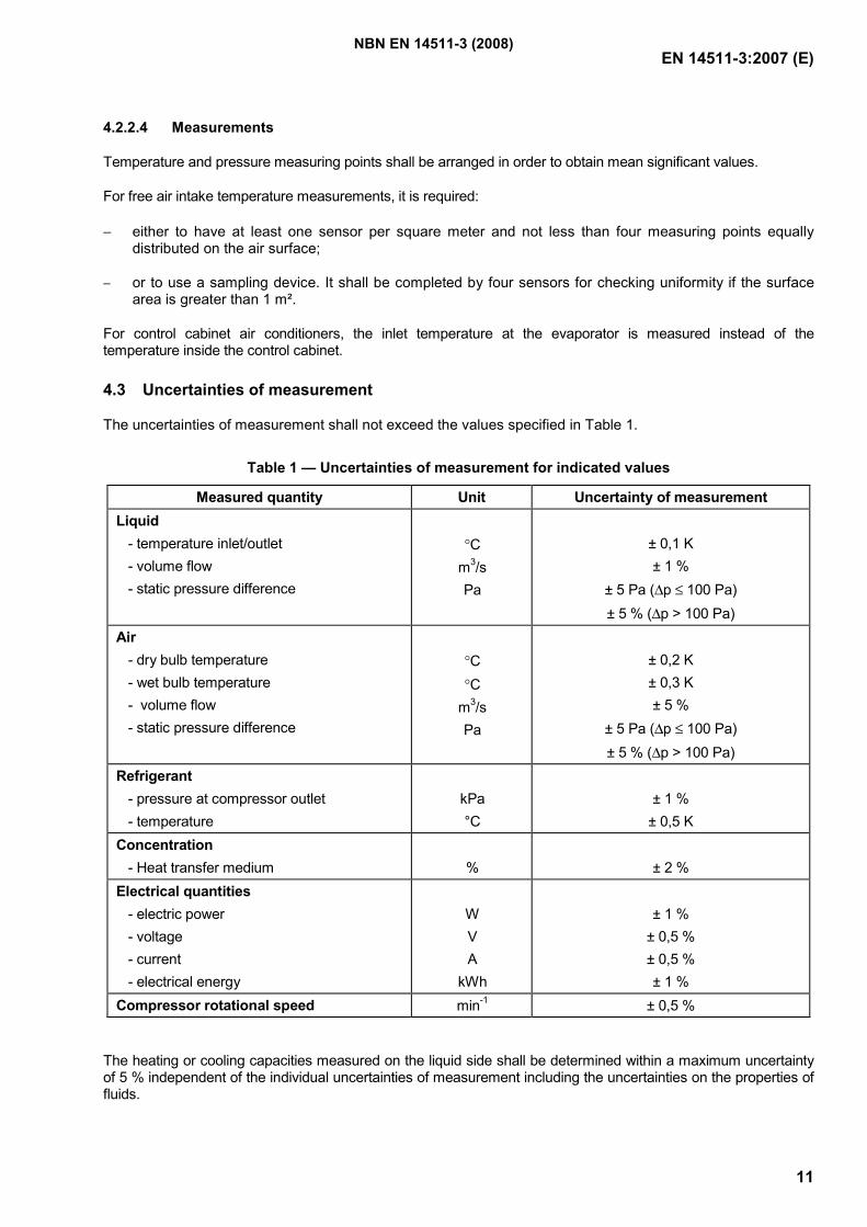
EN 14511-3:2007 (E)
11
4.2.2.4 Measurements
Temperature and pressure measuring points shall be arranged in order to obtain mean significant values.
For free air intake temperature measurements, it is required:
− either to have at least one sensor per square meter and not less than four measuring points equally distributed on the air surface;
− or to use a sampling device. It shall be completed by four sensors for checking uniformity if the surface area is greater than 1 m².
For control cabinet air conditioners, the inlet temperature at the evaporator is measured instead of the temperature inside the control cabinet.
4.3 Uncertainties of measurement
The uncertainties of measurement shall not exceed the values specified in Table 1.
Table 1 — Uncertainties of measurement for indicated values
Measured quantity Unit Uncertainty of measurement Liquid - temperature inlet/outlet - volume flow - static pressure difference
°C m3/s Pa
± 0,1 K ± 1 %
± 5 Pa (∆p ≤ 100 Pa) ± 5 % (∆p > 100 Pa)
Air - dry bulb temperature - wet bulb temperature - volume flow - static pressure difference
°C °C m3/s Pa
± 0,2 K ± 0,3 K ± 5 %
± 5 Pa (∆p ≤ 100 Pa) ± 5 % (∆p > 100 Pa)
Refrigerant - pressure at compressor outlet - temperature
kPa °C
± 1 %
± 0,5 K Concentration - Heat transfer medium
%
± 2 %
Electrical quantities - electric power - voltage - current - electrical energy
W V A kWh
± 1 %
± 0,5 % ± 0,5 % ± 1 %
Compressor rotational speed min-1 ± 0,5 %
The heating or cooling capacities measured on the liquid side shall be determined within a maximum uncertainty of 5 % independent of the individual uncertainties of measurement including the uncertainties on the properties of fluids.
NBN EN 14511-3 (2008)
EN 14511-3:2007 (E)
12
The steady state heating or cooling capacities determined using the calorimeter method shall be determined with a maximum uncertainty of 5 %, independent of the individual uncertainties of measurement including the uncertainties on the properties of fluids.
Heating capacity determined during transient operation (defrost cycles) using the calorimeter method shall be determined with a maximum uncertainty of 10 %, independent of the individual uncertainties of measurement including the uncertainties on the properties of fluids.
The heating and cooling capacities measured on the air side using the air enthalpy method shall be determined with a maximum uncertainty of 10 %, independent of the individual uncertainties of measurement including the uncertainties on the properties of fluids.
4.4 Test procedure
4.4.1 General
4.4.1.1 All units
The test conditions are given in EN 14511-2.
If liquid heat transfer media other than water are used, the specific heat capacity and density of such heat transfer media shall be determined and taken into consideration in the evaluation.
Table 4 states permissible deviations of the measured values from the test conditions.
4.4.1.2 Non ducted units
For non ducted units, the adjustable settings such as louvers and fan speed shall be set for maximum air flow.
4.4.1.3 Ducted units
The volume flow and the pressure difference shall be related to standard air and with dry evaporator.
The air flow rate given by the manufacturer shall be converted into standard air conditions. The air flow rate setting shall be made when the fan only is operating, at standard air conditions.
The rated airflow rate given by the manufacturer shall be set and the resulting external static pressure (ESP) measured. This ESP shall be greater than the minimum value given in Table 2 for comfort air conditioners and Table 3 for close control air conditioners but not greater than 80 % of the maximum external static pressure specified by the manufacturer.
If the fan of the unit has an adjustable speed, it shall be adjusted to the lowest speed that provide the minimum ESP or greater.
If the maximum ESP of the unit is lower than the minimum ESP given in Table 2 or Table 3, then the air flow rate is lowered to achieve an ESP equal to 80 % of the maximum ESP of the manufacturer.
In case this ESP is lower than 25 Pa, the unit can be considered as a free delivery unit and be tested as a non ducted unit with an ESP of 0 Pa.
NBN EN 14511-3 (2008)
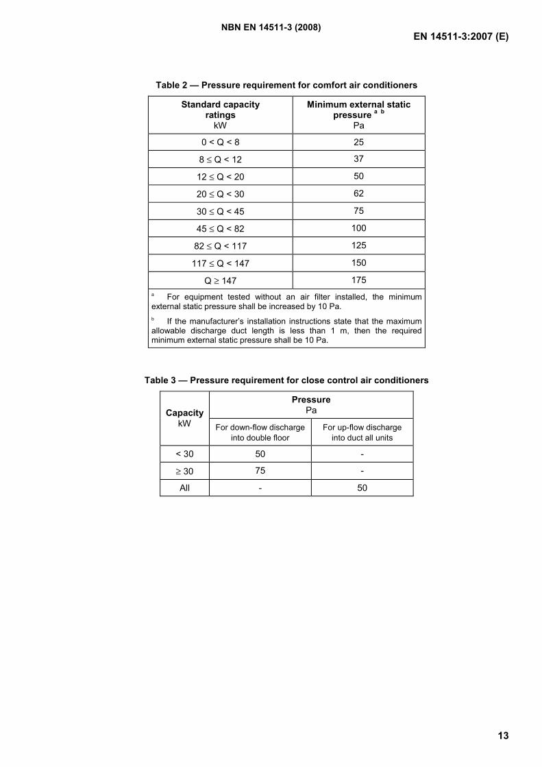
EN 14511-3:2007 (E)
13
Table 2 — Pressure requirement for comfort air conditioners
Standard capacity ratings
kW
Minimum external static pressure a b
Pa
0 < Q < 8 25
8 ≤ Q < 12 37
12 ≤ Q < 20 50
20 ≤ Q < 30 62
30 ≤ Q < 45 75
45 ≤ Q < 82 100
82 ≤ Q < 117 125
117 ≤ Q < 147 150
Q ≥ 147 175 a For equipment tested without an air filter installed, the minimum external static pressure shall be increased by 10 Pa. b If the manufacturer’s installation instructions state that the maximum allowable discharge duct length is less than 1 m, then the required minimum external static pressure shall be 10 Pa.
Table 3 — Pressure requirement for close control air conditioners
Pressure Pa Capacity
kW For down-flow dischargeinto double floor
For up-flow discharge into duct all units
< 30 50 -
≥ 30 75 -
All - 50
NBN EN 14511-3 (2008)
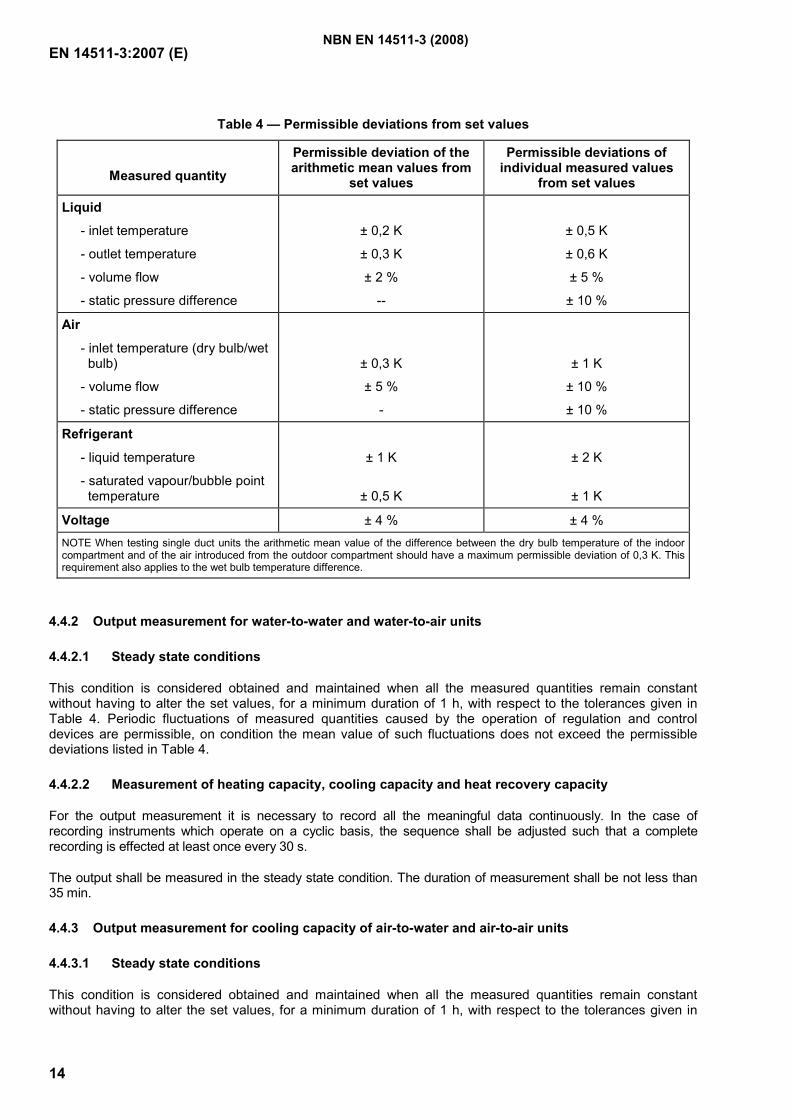
EN 14511-3:2007 (E)
14
Table 4 — Permissible deviations from set values
Measured quantity
Permissible deviation of the arithmetic mean values from
set values
Permissible deviations of individual measured values
from set values
Liquid
- inlet temperature
- outlet temperature
- volume flow
- static pressure difference
± 0,2 K
± 0,3 K
± 2 %
--
± 0,5 K
± 0,6 K
± 5 %
± 10 %
Air
- inlet temperature (dry bulb/wet bulb)
- volume flow
- static pressure difference
± 0,3 K
± 5 %
-
± 1 K
± 10 %
± 10 %
Refrigerant
- liquid temperature
- saturated vapour/bubble point temperature
± 1 K
± 0,5 K
± 2 K
± 1 K
Voltage ± 4 % ± 4 % NOTE When testing single duct units the arithmetic mean value of the difference between the dry bulb temperature of the indoor compartment and of the air introduced from the outdoor compartment should have a maximum permissible deviation of 0,3 K. This requirement also applies to the wet bulb temperature difference.
4.4.2 Output measurement for water-to-water and water-to-air units
4.4.2.1 Steady state conditions
This condition is considered obtained and maintained when all the measured quantities remain constant without having to alter the set values, for a minimum duration of 1 h, with respect to the tolerances given in Table 4. Periodic fluctuations of measured quantities caused by the operation of regulation and control devices are permissible, on condition the mean value of such fluctuations does not exceed the permissible deviations listed in Table 4.
4.4.2.2 Measurement of heating capacity, cooling capacity and heat recovery capacity
For the output measurement it is necessary to record all the meaningful data continuously. In the case of recording instruments which operate on a cyclic basis, the sequence shall be adjusted such that a complete recording is effected at least once every 30 s.
The output shall be measured in the steady state condition. The duration of measurement shall be not less than 35 min.
4.4.3 Output measurement for cooling capacity of air-to-water and air-to-air units
4.4.3.1 Steady state conditions
This condition is considered obtained and maintained when all the measured quantities remain constant without having to alter the set values, for a minimum duration of 1 h, with respect to the tolerances given in
NBN EN 14511-3 (2008)
EN 14511-3:2007 (E)
15
Table 4. Periodic fluctuations of measured quantities caused by the operation of regulation and control devices are permissible, on condition the mean value of such fluctuations does not exceed the permissible deviations listed in Table 4.
4.4.3.2 Measurement of cooling capacity
For the output measurement it is necessary to record all the meaningful data continuously. In the case of recording instruments which operate on a cyclic basis, the sequence shall be adjusted such that a complete recording is effected at least once every 30 s.
The output shall be measured in the steady state condition. The duration of measurement shall be not less than 35 min.
4.4.4 Output measurement for heating capacity of air-to-water and air-to-air units
4.4.4.1 General
The test procedure consists of three periods: a preconditioning period, an equilibrium period, and a data collection period. The duration of the data collection differs depending upon whether the heat pump’s operation is steady state or transient.
Annex C gives a flow chart of the procedure and pictorially represents most of the different test sequences that are possible when conducting a heating capacity test.
4.4.4.2 Preconditioning period
The test room reconditioning apparatus and the heat pump under test shall be operated until the test tolerances specified in Table 4 are attained for at least 10 min.
A defrost cycle may end a preconditioning period. If a defrost cycle does end a preconditioning period, the heat pump shall operate in the heating mode for at least 10 min after defrost termination prior to beginning the equilibrium period.
It is recommended that the preconditioning period end with an automatic or manually-induced defrost cycle when testing at application rating conditions for outdoor air stated in Table 3 and Table 9 of EN 14511-2:2007.
4.4.4.3 Equilibrium period
The equilibrium period immediately follows the preconditioning period or the defrost cycle and a recovery period of 10 min that ends a preconditioning period.
A complete equilibrium period is one hour in duration.
Except as specified in 4.4.4.7, the heat pump shall operate while meeting the test tolerances specified in Table 4.
4.4.4.4 Data collection period
The data collection period immediately follows the equilibrium period.
Data shall be sampled at equal intervals that span every 30 s or less, except during defrost cycles as specified below.
During defrost cycles, plus the first 10 min following defrost termination, data used in evaluating the integrated heating capacity and the integrated power input of the heat pump shall be sampled more frequently, at equal intervals that span every 10 s or less. When using the indoor air enthalpy method, these more frequently
NBN EN 14511-3 (2008)
EN 14511-3:2007 (E)
16
sampled data include the change in indoor-side dry bulb temperature. When using the calorimeter method, these more frequently sampled data include all measurements required to determine the indoor-side capacity.
For heat pumps that automatically cycle off the indoor fan during a defrost, the contribution of the net heating delivered and/or the change in indoor-side dry bulb temperature shall be assigned the value of zero when the indoor fan is off, if using the indoor air enthalpy method. If using the calorimeter test method, the integration of capacity shall continue while the indoor fan is off.
The difference between the leaving and entering temperatures of the heat transfer medium at the indoor heat exchanger shall be measured. For each interval of 5 min during the data collection period, an average temperature difference shall be calculated, ∆Ti (τ). The average temperature difference for the first 5 min of the data collection period, ∆Ti (τ=0), shall be saved for the purpose of calculating the following percent change:
( ) ( )( ) 100
00
% ×
=∆
∆−=∆=∆
τττ
i
ii
TTTT (8)
4.4.4.5 Test procedure: When a defrost cycle ends the preconditioning period
If the quantity %∆T exceeds 2,5 % during the first 35 min of the data collection period, the heating capacity test shall be designated a transient test (see 4.4.4.7). Likewise, if the heat pump initiates a defrost cycle during the equilibrium period or during the first 35 min of the data collection period, the heating capacity test shall be designated a transient test.
If the above conditions do not occur and the test tolerances specified in Table 4 are satisfied during both the equilibrium period and the first 35 min of the data collection period, then the heat capacity test shall be designated a steady-state test. Steady-state tests shall be terminated after 35 min of data collection.
4.4.4.6 Test procedure: When a defrost cycle does not end the preconditioning period
4.4.4.6.1 If the heat pump initiates a defrost cycle during the equilibrium period or during the first 35 min of the data collection period, the heating capacity test shall be restarted as specified 4.4.4.6.3
4.4.4.6.2 If the quantity %∆T exceeds 2,5 % any time during the first 35 min of the data collection period, then the heating capacity test procedure shall be restarted as specified in 4.4.4.6.3. Prior to the restart, defrost cycle shall occur. This defrost cycle may be manually initiated or delayed until the heat pump initiates an automatic defrost.
4.4.4.6.3 If either 4.4.4.6.1 or 4.4.4.6.2 apply, then the restart shall begin 10 min after the defrost cycle terminates with a new equilibrium period of one hour. This second attempt shall follow the requirements of 4.4.4.3 and 4.4.4.4 and the test procedure of 4.4.4.5.
4.4.4.6.4 If the conditions specified in 4.4.4.6.1 or 4.4.4.6.2 do not occur and the test tolerances specified in Table 4 are satisfied during both the equilibrium period and the first 35 min of the data collection period, then the heat capacity test shall be designated a steady-state test. Steady-state tests shall be terminated after 35 min of data collection.
4.4.4.7 Test procedure for transient tests
When, in accordance with 4.4.4.5, a heating capacity test is designated a transient test, the following adjustments shall apply.
To constitute a valid transient heating capacity test, the test tolerances specified in Table 5 shall be achieved during both the equilibrium period and the data collection period. As noted in Table 5, the test tolerances are specified for two sub-intervals. Interval H consists of data collected during each heating interval, with the exception of the first 10 min after defrost termination. Interval D consists of data collected during each defrost cycle plus the first 10 min of the subsequent heating interval.
NBN EN 14511-3 (2008)
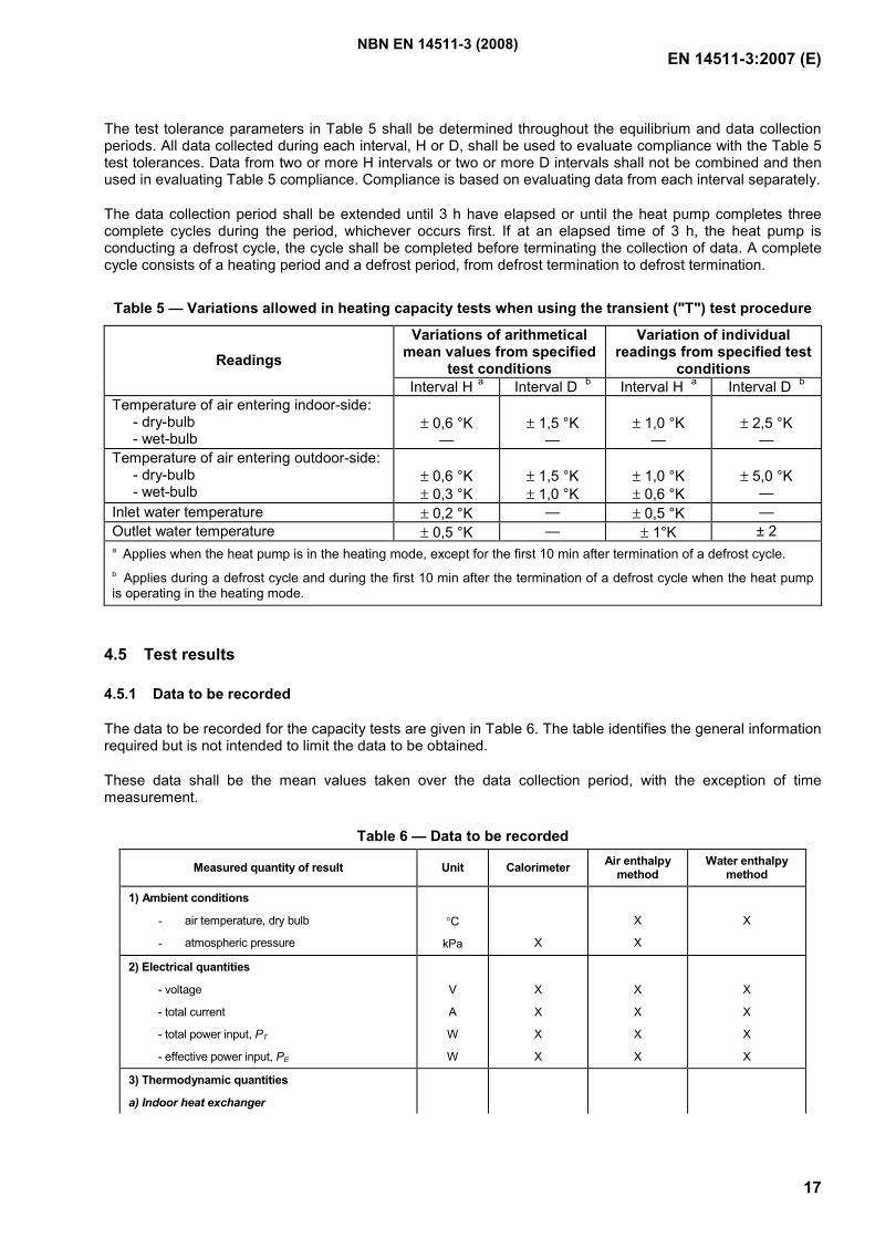
EN 14511-3:2007 (E)
17
The test tolerance parameters in Table 5 shall be determined throughout the equilibrium and data collection periods. All data collected during each interval, H or D, shall be used to evaluate compliance with the Table 5 test tolerances. Data from two or more H intervals or two or more D intervals shall not be combined and then used in evaluating Table 5 compliance. Compliance is based on evaluating data from each interval separately.
The data collection period shall be extended until 3 h have elapsed or until the heat pump completes three complete cycles during the period, whichever occurs first. If at an elapsed time of 3 h, the heat pump is conducting a defrost cycle, the cycle shall be completed before terminating the collection of data. A complete cycle consists of a heating period and a defrost period, from defrost termination to defrost termination.
Table 5 — Variations allowed in heating capacity tests when using the transient ("T") test procedure
Variations of arithmetical mean values from specified
test conditions
Variation of individual readings from specified test
conditions Readings
Interval H a Interval D b Interval H a Interval D b Temperature of air entering indoor-side: - dry-bulb - wet-bulb
± 0,6 °K
—
± 1,5 °K
—
± 1,0 °K
—
± 2,5 °K
— Temperature of air entering outdoor-side: - dry-bulb - wet-bulb
± 0,6 °K ± 0,3 °K
± 1,5 °K ± 1,0 °K
± 1,0 °K ± 0,6 °K
± 5,0 °K
— Inlet water temperature ± 0,2 °K — ± 0,5 °K — Outlet water temperature ± 0,5 °K — ± 1°K ± 2 a Applies when the heat pump is in the heating mode, except for the first 10 min after termination of a defrost cycle. b Applies during a defrost cycle and during the first 10 min after the termination of a defrost cycle when the heat pump is operating in the heating mode.
4.5 Test results
4.5.1 Data to be recorded
The data to be recorded for the capacity tests are given in Table 6. The table identifies the general information required but is not intended to limit the data to be obtained.
These data shall be the mean values taken over the data collection period, with the exception of time measurement.
Table 6 — Data to be recorded
Measured quantity of result Unit Calorimeter Air enthalpy method
Water enthalpy method
1) Ambient conditions
- air temperature, dry bulb
- atmospheric pressure
°C
kPa
X
X
X
X
2) Electrical quantities
- voltage
- total current
- total power input, PT
- effective power input, PE
V
A
W
W
X
X
X
X
X
X
X
X
X
X
X
X
3) Thermodynamic quantities
a) Indoor heat exchanger
NBN EN 14511-3 (2008)
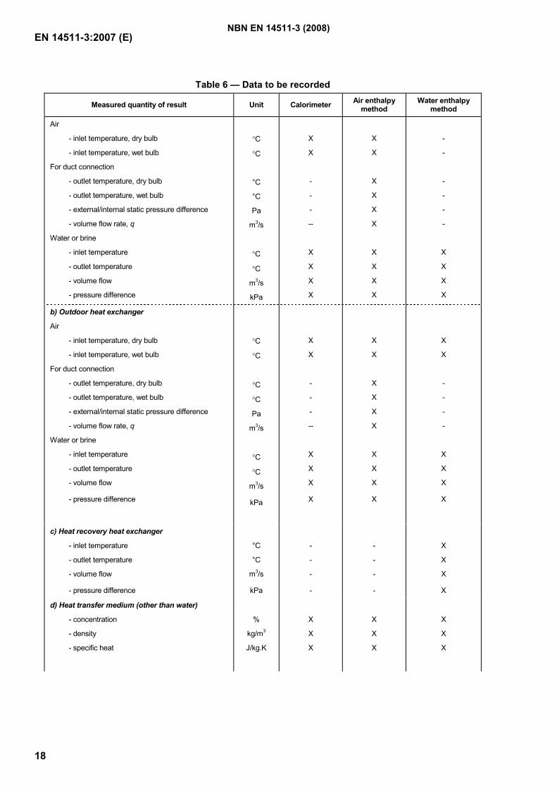
EN 14511-3:2007 (E)
18
Table 6 — Data to be recorded
Measured quantity of result Unit Calorimeter Air enthalpy method
Water enthalpy method
Air
- inlet temperature, dry bulb
- inlet temperature, wet bulb
For duct connection
- outlet temperature, dry bulb
- outlet temperature, wet bulb
- external/internal static pressure difference
- volume flow rate, q
Water or brine
- inlet temperature
- outlet temperature
- volume flow
- pressure difference
°C
°C
°C
°C
Pa
m3/s
°C
°C
m3/s
kPa
X
X
-
-
-
--
X
X
X
X
X
X
X
X
X
X
X
X
X
X
-
-
-
-
-
-
X
X
X
X
b) Outdoor heat exchanger
Air
- inlet temperature, dry bulb
- inlet temperature, wet bulb
For duct connection
- outlet temperature, dry bulb
- outlet temperature, wet bulb
- external/internal static pressure difference
- volume flow rate, q
Water or brine
- inlet temperature
- outlet temperature
- volume flow
- pressure difference
°C
°C
°C
°C
Pa
m3/s
°C
°C
m3/s
kPa
X
X
-
-
-
--
X
X
X
X
X
X
X
X
X
X
X
X
X
X
X
X
-
-
-
-
X
X
X
X
c) Heat recovery heat exchanger
- inlet temperature
- outlet temperature
- volume flow
- pressure difference
°C
°C
m3/s
kPa
-
-
-
-
-
-
-
-
X
X
X
X
d) Heat transfer medium (other than water)
- concentration
- density
- specific heat
%
kg/m3
J/kg.K
X
X
X
X
X
X
X
X
X
NBN EN 14511-3 (2008)
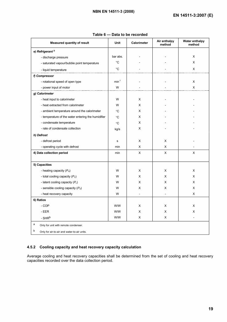
EN 14511-3:2007 (E)
19
Table 6 — Data to be recorded
Measured quantity of result Unit Calorimeter Air enthalpy method
Water enthalpy method
e) Refrigerant a
- discharge pressure
- saturated vapour/bubble point temperature
- liquid temperature
bar abs.
°C
°C
-
-
-
-
-
-
X
X
X
f) Compressor
- rotational speed of open type
- power input of motor
min-1
W
-
-
-
-
X
X
g) Calorimeter
- heat input to calorimeter
- heat extracted from calorimeter
- ambient temperature around the calorimeter
- temperature of the water entering the humidifier
- condensate temperature
- rate of condensate collection
W
W
°C
°C
°C
kg/s
X
X
X
X
X
X
-
-
-
-
-
-
-
-
-
-
-
-
h) Defrost
- defrost period
- operating cycle with defrost
s
min
X
X
X
X
-
-
4) Data collection period min X
X
X
5) Capacities
- heating capacity (PH)
- total cooling capacity (PC)
- latent cooling capacity (PL)
- sensible cooling capacity (PS)
- heat recovery capacity
W
W
W
W
W
X
X
X
X
-
X
X
X
X
-
X
X
X
X
X
6) Ratios
- COP
- EER
- SHRb
W/W
W/W
W/W
X
X
X
X
X
X
X
X
-
a Only for unit with remote condenser.
b Only for air-to-air and water-to-air units.
4.5.2 Cooling capacity and heat recovery capacity calculation
Average cooling and heat recovery capacities shall be determined from the set of cooling and heat recovery capacities recorded over the data collection period.
NBN EN 14511-3 (2008)
EN 14511-3:2007 (E)
20
4.5.3 Heating capacity calculation
4.5.3.1 Steady state capacity test
An average heating capacity shall be determined from the set of heating capacities recorded over the data collection period of 35 min.
4.5.3.2 Transient capacity test
For equipment where one or more complete cycle occur during the data collection period, the following shall apply. The average heating capacity shall be determined using the integrated capacity and the elapsed time corresponding to the total number of complete cycles that occurred over the data collection period.
For equipment where no complete cycle occurs during the data collection period, the following shall apply. The average heating capacity shall be determined by using the integrated capacity and the elapsed time corresponding to the total data collection period.
4.5.4 Effective power input calculation
4.5.4.1 Steady state test
An average electric power input shall be determined from the integrated electrical power over the same data collection period than the one used for the heating / cooling capacity or heat recovery capacity calculation.
4.5.4.2 Transient with defrost cycle
An average electric power input shall be determined on the basis of the integrated electrical power and the time corresponding to the total number of complete cycles during the same data collection period as the one used for the heat capacity calculation.
4.5.4.3 Transient without defrost cycle
An average electric power input shall be determined on the basis of the integrated electrical power and the time corresponding to the same data collection period as the one used for the heat capacity calculation.
5 Heat recovery test for air-cooled multisplit systems
5.1 Test installation
5.1.1 General
The heat recovery capacity of the system is determined by measurements in a three room calorimeter or by the air enthalpy method using two or three rooms. The three rooms shall consist of one outdoor room and two indoor rooms, one at the heating condition and the other at the cooling condition. The two room air enthalpy method shall have one room at the outdoor condition and the other at the common indoor side condition given in Table 15 of EN 14511-2:2007.
The calorimeter room and air enthalpy methods are described in Annex A and Annex B respectively. Each calorimeter room should satisfy the requirements of Annex A and the test facilities for the air enthalpy method should satisfy the requirements of Annex B.
NBN EN 14511-3 (2008)
EN 14511-3:2007 (E)
21
5.1.2 Three-room calorimeter method
If measurements are made by the calorimeter method, then the testing of a heat recovery system shall need a three-room calorimeter test facility. The indoor units in the cooling mode shall be assembled in one room and the indoor units in the heating mode in the other. The outdoor unit shall be installed in the third room.
5.1.3 Three-room air-enthalpy method
The indoor units in the cooling mode shall be assembled in one room and the indoor units in the heating mode in another room; the outdoor unit shall be installed in the third room.
5.1.4 Two-room air-enthalpy method
All indoor units, either operating in cooling or heating mode, are assembled in one indoor room. The outdoor unit shall be installed in the other room.
All units operating in the heating mode should be connected to a common plenum, all units operating in the cooling mode should be connected to another common plenum, both in accordance with the requirements established in Annex B.
5.2 Test procedure
The heat recovery test shall be carried out with all operating indoor units.
For ducted indoor units, the individual external static pressure of each indoor unit is set by adjusting a damper located in the duct length connecting the discharge area of the unit to the common plenum.
5.3 Test results
Test results are recorded and expressed as specified in 4.5.
The references of the indoor units operating in cooling mode and of the indoor units operating in heating mode shall be specified.
6 Test report
6.1 General information
The test report shall at least contain:
a) date;
b) test institute;
c) test location;
d) test method;
e) test supervisor;
f) test object designation:
Type;
serial number;
NBN EN 14511-3 (2008)
EN 14511-3:2007 (E)
22
name of the manufacturer;
year of initial installation;
g) type of refrigerant;
h) mass of refrigerant;
i) properties of fluids;
j) reference to this European Standard.
6.2 Additional information
Additional information given on the rating plate shall be noted and any other information relevant for the test. Particularly, it shall be stated whether the test is performed on a unit new or not. In the case of a test performed on a unit in use, information relative to the year of installation, and heat exchange tubes cleaning shall be given.
6.3 Rating test results
The rating capacities, power inputs, COP, EER, internal or external static pressure shall be given together with the rating conditions.
NBN EN 14511-3 (2008)
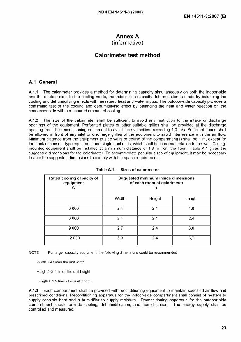
EN 14511-3:2007 (E)
23
Annex A (informative)
Calorimeter test method
A.1 General
A.1.1 The calorimeter provides a method for determining capacity simultaneously on both the indoor-side and the outdoor-side. In the cooling mode, the indoor-side capacity determination is made by balancing the cooling and dehumidifying effects with measured heat and water inputs. The outdoor-side capacity provides a confirming test of the cooling and dehumidifying effect by balancing the heat and water rejection on the condenser side with a measured amount of cooling.
A.1.2 The size of the calorimeter shall be sufficient to avoid any restriction to the intake or discharge openings of the equipment. Perforated plates or other suitable grilles shall be provided at the discharge opening from the reconditioning equipment to avoid face velocities exceeding 1,0 m/s. Sufficient space shall be allowed in front of any inlet or discharge grilles of the equipment to avoid interference with the air flow. Minimum distance from the equipment to side walls or ceiling of the compartment(s) shall be 1 m, except for the back of console-type equipment and single duct units, which shall be in normal relation to the wall. Ceiling-mounted equipment shall be installed at a minimum distance of 1,8 m from the floor. Table A.1 gives the suggested dimensions for the calorimeter. To accommodate peculiar sizes of equipment, it may be necessary to alter the suggested dimensions to comply with the space requirements.
Table A.1 — Sizes of calorimeter
Rated cooling capacity of equipment
W
Suggested minimum inside dimensions of each room of calorimeter
m
Width Height Length
3 000 2,4 2,1 1,8
6 000 2,4 2,1 2,4
9 000 2,7 2,4 3,0
12 000 3,0 2,4 3,7
NOTE For larger capacity equipment, the following dimensions could be recommended:
Width ≥ 4 times the unit width
Height ≥ 2,5 times the unit height
Length ≥ 1,5 times the unit length.
A.1.3 Each compartment shall be provided with reconditioning equipment to maintain specified air flow and prescribed conditions. Reconditioning apparatus for the indoor-side compartment shall consist of heaters to supply sensible heat and a humidifier to supply moisture. Reconditioning apparatus for the outdoor-side compartment should provide cooling, dehumidification, and humidification. The energy supply shall be controlled and measured.
NBN EN 14511-3 (2008)
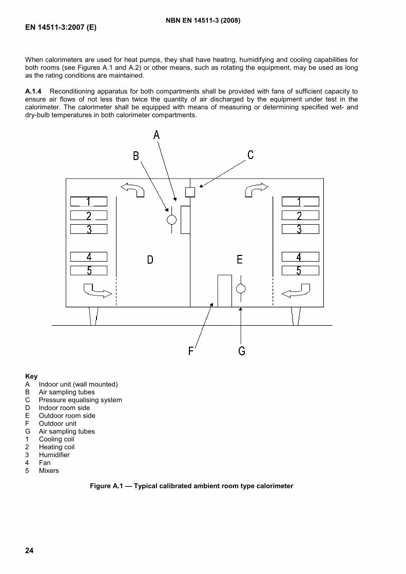
EN 14511-3:2007 (E)
24
When calorimeters are used for heat pumps, they shall have heating, humidifying and cooling capabilities for both rooms (see Figures A.1 and A.2) or other means, such as rotating the equipment, may be used as long as the rating conditions are maintained.
A.1.4 Reconditioning apparatus for both compartments shall be provided with fans of sufficient capacity to ensure air flows of not less than twice the quantity of air discharged by the equipment under test in the calorimeter. The calorimeter shall be equipped with means of measuring or determining specified wet- and dry-bulb temperatures in both calorimeter compartments.
Key A Indoor unit (wall mounted) B Air sampling tubes C Pressure equalising system D Indoor room side E Outdoor room side F Outdoor unit G Air sampling tubes 1 Cooling coil 2 Heating coil 3 Humidifier 4 Fan 5 Mixers
Figure A.1 — Typical calibrated ambient room type calorimeter
NBN EN 14511-3 (2008)
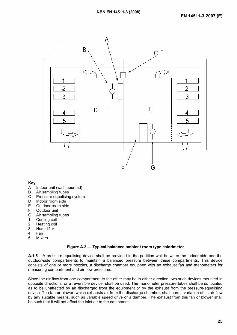
EN 14511-3:2007 (E)
25
Key A Indoor unit (wall mounted) B Air sampling tubes C Pressure equalising system D Indoor room side E Outdoor room side F Outdoor unit G Air sampling tubes 1 Cooling coil 2 Heating coil 3 Humidifier 4 Fan 5 Mixers
Figure A.2 — Typical balanced ambient room type calorimeter
A.1.5 A pressure-equalising device shall be provided in the partition wall between the indoor-side and the outdoor-side compartments to maintain a balanced pressure between these compartments. This device consists of one or more nozzles, a discharge chamber equipped with an exhaust fan and manometers for measuring compartment and air flow pressures.
Since the air flow from one compartment to the other may be in either direction, two such devices mounted in opposite directions, or a reversible device, shall be used. The manometer pressure tubes shall be so located as to be unaffected by air discharged from the equipment or by the exhaust from the pressure-equalising device. The fan or blower, which exhausts air from the discharge chamber, shall permit variation of its air flow by any suitable means, such as variable speed drive or a damper. The exhaust from this fan or blower shall be such that it will not affect the inlet air to the equipment.
NBN EN 14511-3 (2008)
EN 14511-3:2007 (E)
26
A.1.6 It is recognised that in both the indoor-side and outdoor-side compartments, temperature gradients and air flow patterns result from the interaction of the reconditioning apparatus and test equipment. Therefore, the resultant conditions are peculiar to and dependent upon a given combination of compartment size, arrangement and size of reconditioning apparatus, and the air discharge characteristics of the equipment under test.
The point of measurement of the specified test temperatures, both wet- and dry-bulb, shall be such that the following conditions are fulfilled.
a) The measured temperatures shall be representative of the temperature surrounding each piece of the equipment and shall simulate the conditions encountered in an actual application for both indoor and outdoor sides, as indicated above.
b) At the point of measurement, the temperature of air shall not be affected by air discharged from any piece of the equipment. This makes it mandatory that the temperatures are measured upstream of any recirculation produced by the equipment.
Air sampling tubes shall be positioned on the intake side of the equipment.
A.1.7 Interior surfaces of the calorimeter compartments shall be of non-porous material with all joints sealed against air and moisture leakage. The access door shall be tightly sealed against air and moisture leakage by use of gaskets or other suitable means.
A.2 Transient heating capacity test
If defrost controls on the heat pump provide for stopping the indoor air flow, provision shall be made to stop the test apparatus air flow to the equipment on both the indoor and outdoor-sides during such a defrost period. If it is desirable to maintain operation of the reconditioning apparatus during the defrost period, provision may be made to bypass the conditioned air around the equipment as long as assurance is provided that the conditioned air does not aid in the defrosting. A watt-hour meter shall be used for obtaining the integrated electrical input to the equipment under test.
A.3 Calibrated room-type calorimeter
A.3.1 The calibrated room-type calorimeter is shown in Figure A.1. Each calorimeter, including the separating partition, shall be insulated to prevent heat leakage (including radiation) in excess of 5 % of the equipment's capacity. An air space permitting free circulation shall be provided under the calorimeter floor.
A.3.2 Heat leakage may be determined in either the indoor-side or outdoor-side compartment by the following method: all openings shall be closed. Either compartment may be heated by electric heaters to a temperature of at least 11 °K above the surrounding ambient temperature. The ambient temperature shall be maintained constant within ± 1 °K outside all six enveloping surfaces of the compartment, including the separating partition. If the construction of the partition is identical with that of the other walls, the heat leakage through the partition may be determined on a proportional area basis.
A.3.3 For calibrating the heat leakage through the separating partition alone, the following procedure may be used: a test is carried out as described above. Then the temperature of the adjoining area on the other side of the separating partition is raised to equal the temperature in the heated compartment, thus eliminating heat leakage through the partition, while the 11 °K differential is maintained between the heated compartment and the ambient surrounding the other five enveloping surfaces.
The difference in heat input between the first test and second test will permit the determination of the leakage through the partition alone.
NBN EN 14511-3 (2008)
EN 14511-3:2007 (E)
27
A.3.4 For the outdoor-side compartment equipped with means for cooling, an alternative means of calibration may be to cool the compartment to a temperature at least 11 °K below the ambient temperature (on six sides) and carry out a similar analysis.
A.3.5 As an alternative to the two-room simultaneous method of determining capacities, the performance of the indoor room-side compartment may be verified at least every six months using an industry standard cooling capacity calibrating device. A calibrating device may also be another piece of equipment whose performance has been measured by the simultaneous indoor and outdoor measurement method at an accredited national test laboratory as part of an industry-wide cooling capacity verification program.
A.4 Balanced ambient room-type calorimeter
A.4.1 The balanced ambient room-type calorimeter is shown in Figure A.2 and is based on the principle of maintaining the dry-bulb temperatures surrounding the particular compartment equal to the dry-bulb temperatures maintained within that compartment. If the ambient wet-bulb temperature is also maintained equal to that within the compartment, the vapour-proofing provisions of A.1.6 are not required.
A.4.2 The floor, ceiling, and walls of the calorimeter compartments shall be spaced a sufficient distance away from the floor, ceiling, and walls of the controlled areas in which the compartments are located in order to provide a uniform air temperature in the intervening space. It is recommended that this distance be at least 0,3 m. Means shall be provided to circulate the air within the surrounding space to prevent stratification.
A.4.3 Heat leakage through the separating partition shall be introduced into the heat balance calculation and may be calibrated in accordance with A.3.3, or may be calculated.
A.4.4 It is recommended that the floor, ceiling, and walls of the calorimeter compartments be insulated so as to limit heat leakage (including radiation) to no more than 10 % of the test equipment's capacity, with an 11 °K temperature difference, or 300 W for the same temperature difference, whichever is greater, as tested using the procedure given in A.3.2.
A.5 Calorimeter and auxiliary equipment for water-cooled condenser tests
A.5.1 The indoor-side compartment of a room calorimeter of either the calibrated or the balanced ambient type shall be used.
A.5.2 Measurements shall be made for determining flow and temperature rise of condenser cooling water. Water lines shall be insulated between the condenser and points of temperature measurement.
A.6 Calculations-cooling capacities
A.6.1 General
The energy flow quantities used to calculate the total cooling capacity based on indoor and outdoor-side measurements are shown below in Figure A.3.
NBN EN 14511-3 (2008)
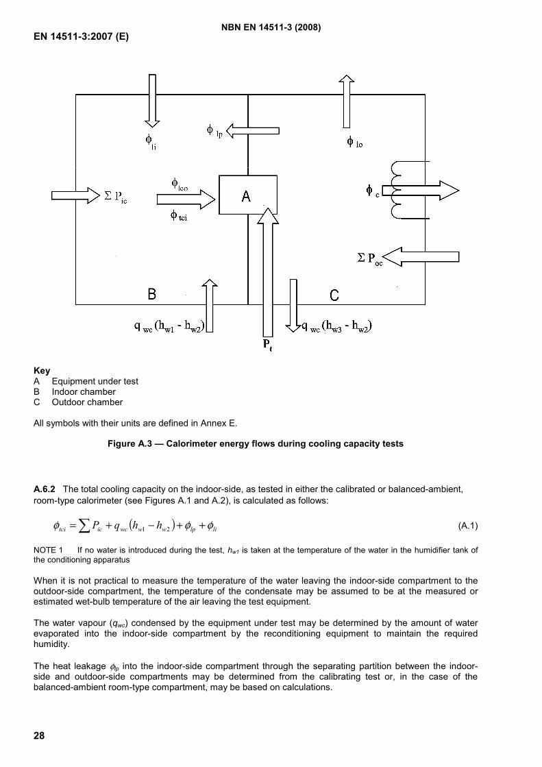
EN 14511-3:2007 (E)
28
Key A Equipment under test B Indoor chamber C Outdoor chamber All symbols with their units are defined in Annex E.
Figure A.3 — Calorimeter energy flows during cooling capacity tests
A.6.2 The total cooling capacity on the indoor-side, as tested in either the calibrated or balanced-ambient, room-type calorimeter (see Figures A.1 and A.2), is calculated as follows:
( ) lilpwwwcictci hhqP φφφ ++−+=∑ 21 (A.1)
NOTE 1 If no water is introduced during the test, hw1 is taken at the temperature of the water in the humidifier tank of the conditioning apparatus
When it is not practical to measure the temperature of the water leaving the indoor-side compartment to the outdoor-side compartment, the temperature of the condensate may be assumed to be at the measured or estimated wet-bulb temperature of the air leaving the test equipment.
The water vapour (qwc) condensed by the equipment under test may be determined by the amount of water evaporated into the indoor-side compartment by the reconditioning equipment to maintain the required humidity.
The heat leakage φlp into the indoor-side compartment through the separating partition between the indoor-side and outdoor-side compartments may be determined from the calibrating test or, in the case of the balanced-ambient room-type compartment, may be based on calculations.
NBN EN 14511-3 (2008)
EN 14511-3:2007 (E)
29
The total cooling capacity on the outdoor-side, as tested in either the calibrated or balanced-ambient, room-type calorimeter (see Figures A.1 and A.2), is calculated as follows:
( ) lolpwwwctocctco hhqPP φφφφ ++−+−= ∑− 23 (A.2)
NOTE 2 The hw3 enthalpy is taken at the temperature at which the condensate leaves the outdoor-side compartment.
The heat leakage rate (φlp) into the indoor-side compartment through the separating partition between the indoor-side and outdoor-side compartments may be determined from the calibrating test or, in the case of the balanced-ambient room-type compartment, may be based on calculations.
NOTE 3 This quantity will be numerically equal to that used in Equation (A.1) if, and only if, the area of the separating partition exposed to the outdoor-side is equal to the area exposed to the indoor-side compartment.
A.6.3 The total cooling capacity of liquid (water)-cooled equipment deducted from the condenser side is calculated as follows:
∑−= Ecotco Pφφ (A.3)
A.6.4 The latent cooling capacity (room dehumidifying capacity) is calculated as follows:
wcd qK1=φ (A.4)
A.6.5 The sensible cooling capacity is calculated as follows:
dtcis φφφ −= (A.5)
A.6.6 Sensible heat ratio is calculated as follows:
tcisSHR
φφ= (A.6)
A.7 Calculation-heating capacities
A.7.1 General
The energy flow quantities used to calculate the total heating capacity based on indoor and outdoor-side measurements are shown below in Figure A.4.
NBN EN 14511-3 (2008)
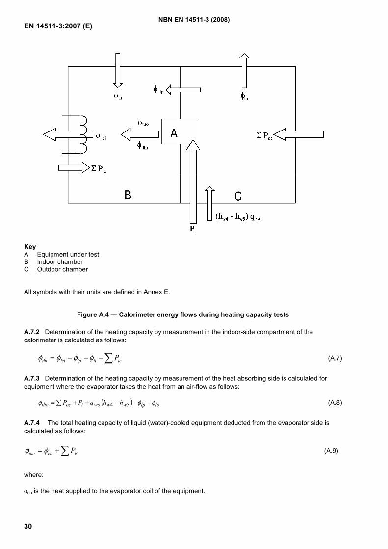
EN 14511-3:2007 (E)
30
Key A Equipment under test B Indoor chamber C Outdoor chamber
All symbols with their units are defined in Annex E.
Figure A.4 — Calorimeter energy flows during heating capacity tests
A.7.2 Determination of the heating capacity by measurement in the indoor-side compartment of the calorimeter is calculated as follows:
∑−−−= iclilplcithi Pφφφφ (A.7)
A.7.3 Determination of the heating capacity by measurement of the heat absorbing side is calculated for equipment where the evaporator takes the heat from an air-flow as follows:
( ) lolpwwwotoctho hhqPP φφφ −−−++= ∑ 54 (A.8)
A.7.4 The total heating capacity of liquid (water)-cooled equipment deducted from the evaporator side is calculated as follows:
∑+= Eeotho Pφφ (A.9)
where:
φeo is the heat supplied to the evaporator coil of the equipment.
NBN EN 14511-3 (2008)
EN 14511-3:2007 (E)
31
Annex B (informative)
Indoor air enthalpy test method
B.1 General
In the air-enthalpy method, capacities are determined from measurements of entering and leaving wet- and dry-bulb temperatures and the associated airflow rate.
B.2 Application
B.2.1 Packaged units and single split units shall have a duct section attached to the outlet area of the indoor section for connection to the air flow measuring device.
Multisplit systems shall have short plenums attached to each indoor unit. Each plenum shall discharge into a common duct section, the duct section in turn discharging into an air measuring device. Each plenum shall have an adjustable restrictor located in the plane where the plenums enter the common duct section for the purpose of adjusting the static pressures in each plenum to the manufacturer's specifications.
The length of the duct section for package and single split systems and the length of the individual plenums for multisplit systems is a minimum of ( )( )π÷××× BA45,2 where A = width and B = height of duct or outlet.
Static pressure readings are taken at a distance of ( )BA××2 from the outlet.
B.2.2 Airflow measurements shall be made in accordance with the provisions specified in ISO 5221, and EN ISO 5167-1 as appropriate, and the provisions in this annex.
B.3 Calculations-cooling capacities
Total, sensible and latent indoor cooling capacities based on the indoor-side test data are calculated by the following equations:
( )( ) 10001
21
nn
aavitci Wv
hhq+′
−=φ
( )( )nn
apaapavis Wv
tctcq+′−
=1
2211φ
( )( ) 10001
211
nn
iivid Wv
WWqK+′
−=φ
stcid φφφ −=
(B.1)
(B.2)
(B.3)
(B.4)
NOTE All symbols and their units are defined in Annex E.
NBN EN 14511-3 (2008)
EN 14511-3:2007 (E)
32
B.4 Calculations-heating capacities
B.4.1 Total heating capacity based on indoor-side data is calculated by the following equation:
( )( )nn
apaapavithi Wv
tctcq+′
−=
11122φ (B.5)
NOTE 1 Equations B.1, B.2, B.3 and B.5 do not provide allowance for heat leakage in the duct section.
NOTE 2 All symbols and their units are defined in Annex E.
NBN EN 14511-3 (2008)
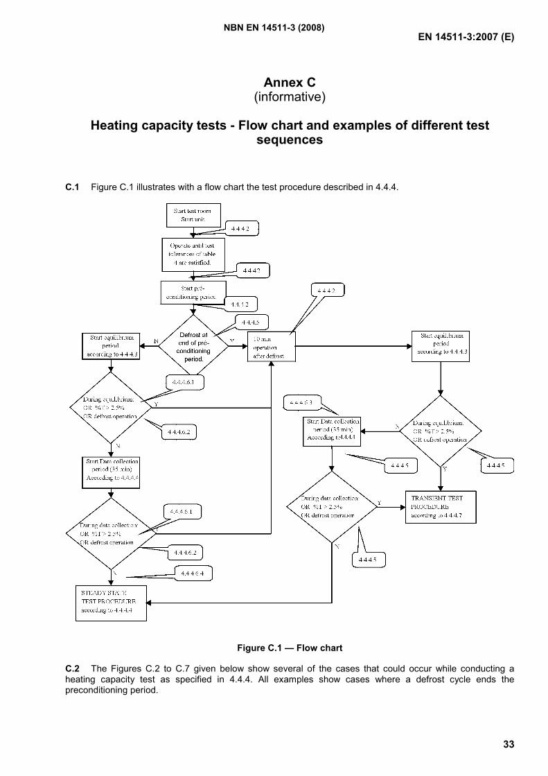
EN 14511-3:2007 (E)
33
Annex C (informative)
Heating capacity tests - Flow chart and examples of different test
sequences
C.1 Figure C.1 illustrates with a flow chart the test procedure described in 4.4.4.
Figure C.1 — Flow chart
C.2 The Figures C.2 to C.7 given below show several of the cases that could occur while conducting a heating capacity test as specified in 4.4.4. All examples show cases where a defrost cycle ends the preconditioning period.
NBN EN 14511-3 (2008)
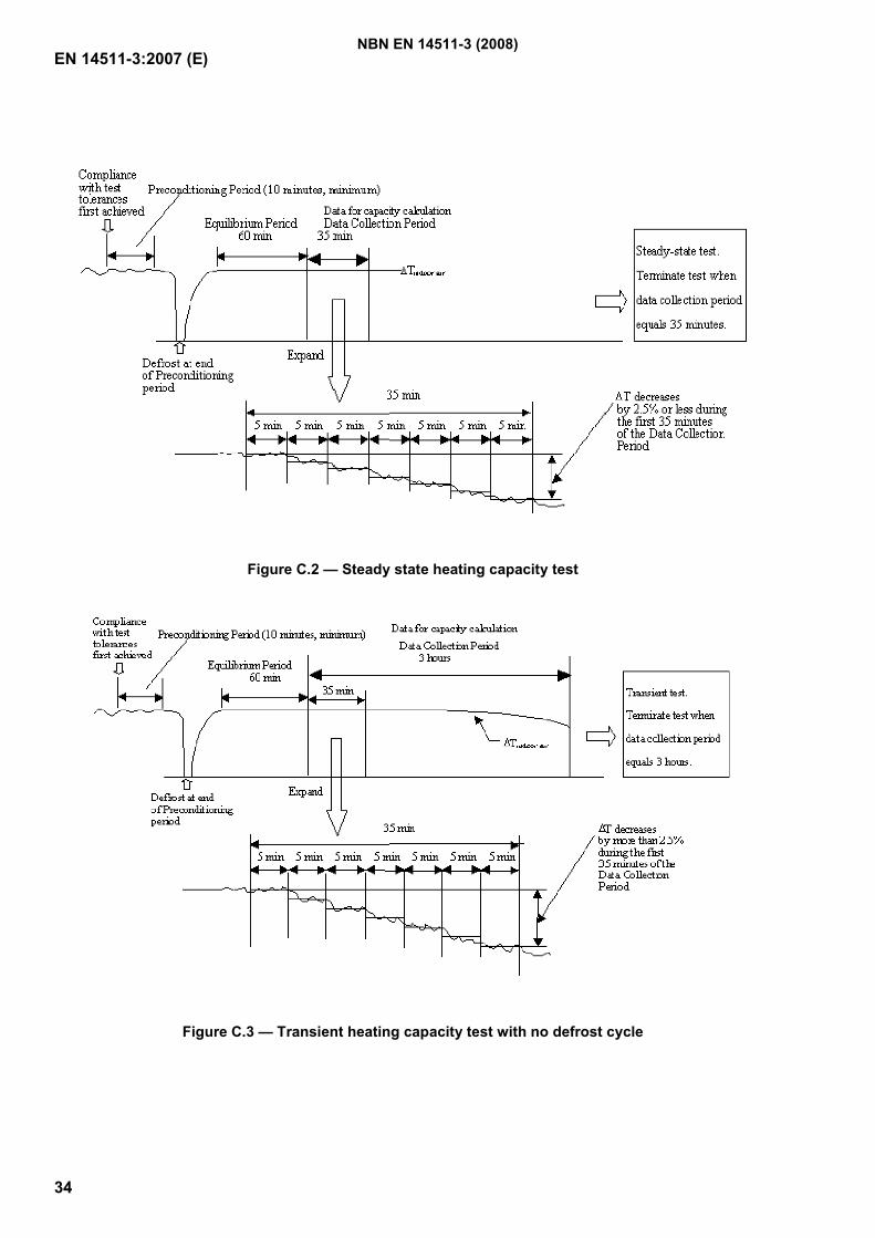
EN 14511-3:2007 (E)
34
Figure C.2 — Steady state heating capacity test
Figure C.3 — Transient heating capacity test with no defrost cycle
NBN EN 14511-3 (2008)
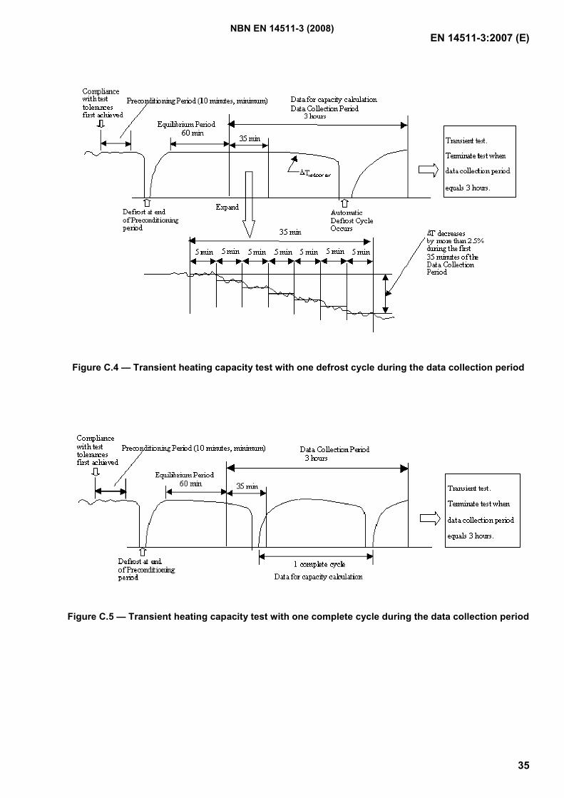
EN 14511-3:2007 (E)
35
Figure C.4 — Transient heating capacity test with one defrost cycle during the data collection period
Figure C.5 — Transient heating capacity test with one complete cycle during the data collection period
NBN EN 14511-3 (2008)
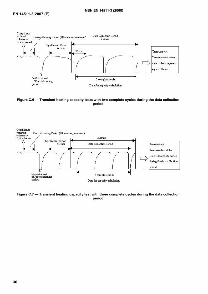
EN 14511-3:2007 (E)
36
Figure C.6 — Transient heating capacity tests with two complete cycles during the data collection period
Figure C.7 — Transient heating capacity test with three complete cycles during the data collection period
NBN EN 14511-3 (2008)
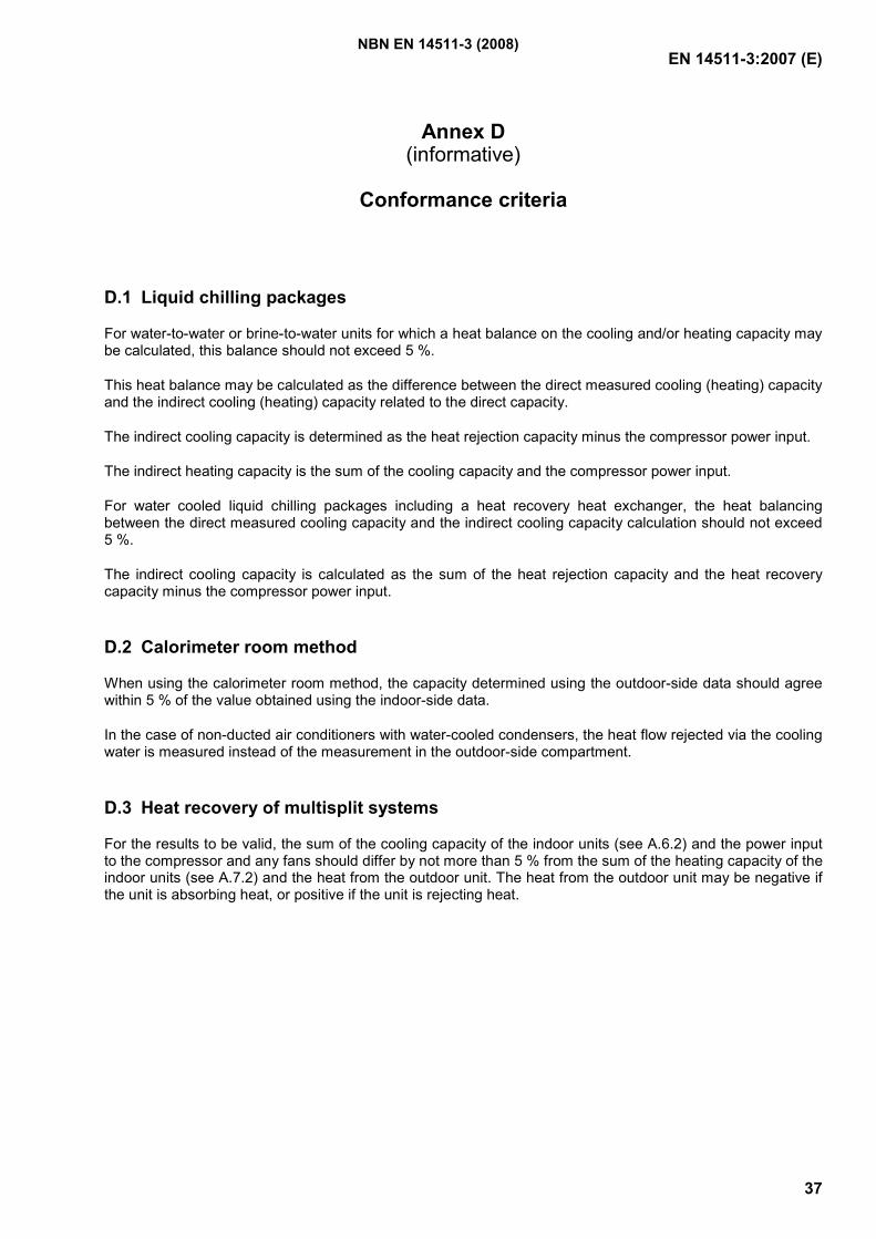
EN 14511-3:2007 (E)
37
Annex D (informative)
Conformance criteria
D.1 Liquid chilling packages
For water-to-water or brine-to-water units for which a heat balance on the cooling and/or heating capacity may be calculated, this balance should not exceed 5 %.
This heat balance may be calculated as the difference between the direct measured cooling (heating) capacity and the indirect cooling (heating) capacity related to the direct capacity.
The indirect cooling capacity is determined as the heat rejection capacity minus the compressor power input.
The indirect heating capacity is the sum of the cooling capacity and the compressor power input.
For water cooled liquid chilling packages including a heat recovery heat exchanger, the heat balancing between the direct measured cooling capacity and the indirect cooling capacity calculation should not exceed 5 %.
The indirect cooling capacity is calculated as the sum of the heat rejection capacity and the heat recovery capacity minus the compressor power input.
D.2 Calorimeter room method
When using the calorimeter room method, the capacity determined using the outdoor-side data should agree within 5 % of the value obtained using the indoor-side data.
In the case of non-ducted air conditioners with water-cooled condensers, the heat flow rejected via the cooling water is measured instead of the measurement in the outdoor-side compartment.
D.3 Heat recovery of multisplit systems
For the results to be valid, the sum of the cooling capacity of the indoor units (see A.6.2) and the power input to the compressor and any fans should differ by not more than 5 % from the sum of the heating capacity of the indoor units (see A.7.2) and the heat from the outdoor unit. The heat from the outdoor unit may be negative if the unit is absorbing heat, or positive if the unit is rejecting heat.
NBN EN 14511-3 (2008)
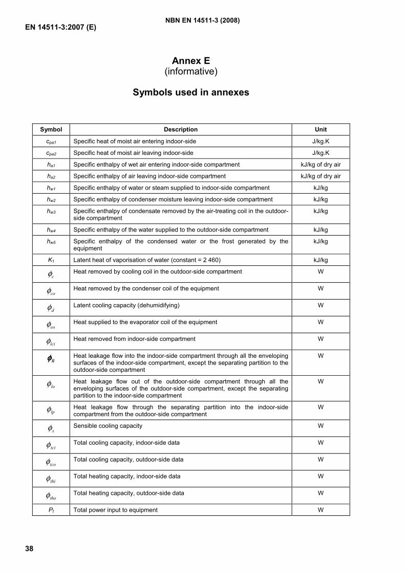
EN 14511-3:2007 (E)
38
Annex E (informative)
Symbols used in annexes
Symbol Description Unit
cpa1 Specific heat of moist air entering indoor-side J/kg.K
cpa2 Specific heat of moist air leaving indoor-side J/kg.K
ha1 Specific enthalpy of wet air entering indoor-side compartment kJ/kg of dry air
ha2 Specific enthalpy of air leaving indoor-side compartment kJ/kg of dry air
hw1 Specific enthalpy of water or steam supplied to indoor-side compartment kJ/kg
hw2 Specific enthalpy of condenser moisture leaving indoor-side compartment kJ/kg
hw3 Specific enthalpy of condensate removed by the air-treating coil in the outdoor-side compartment
kJ/kg
hw4 Specific enthalpy of the water supplied to the outdoor-side compartment kJ/kg
hw5 Specific enthalpy of the condensed water or the frost generated by the equipment
kJ/kg
K1 Latent heat of vaporisation of water (constant = 2 460) kJ/kg
cφ Heat removed by cooling coil in the outdoor-side compartment W
coφ Heat removed by the condenser coil of the equipment W
dφ Latent cooling capacity (dehumidifying) W
eoφ Heat supplied to the evaporator coil of the equipment W
lciφ Heat removed from indoor-side compartment W
liφφφφ Heat leakage flow into the indoor-side compartment through all the enveloping surfaces of the indoor-side compartment, except the separating partition to the outdoor-side compartment
W
loφ Heat leakage flow out of the outdoor-side compartment through all the enveloping surfaces of the outdoor-side compartment, except the separating partition to the indoor-side compartment
W
lpφ Heat leakage flow through the separating partition into the indoor-side compartment from the outdoor-side compartment
W
sφ Sensible cooling capacity W
tciφ Total cooling capacity, indoor-side data W
tcoφ Total cooling capacity, outdoor-side data W
thiφ Total heating capacity, indoor-side data W
thoφ Total heating capacity, outdoor-side data W
Pt Total power input to equipment W
NBN EN 14511-3 (2008)
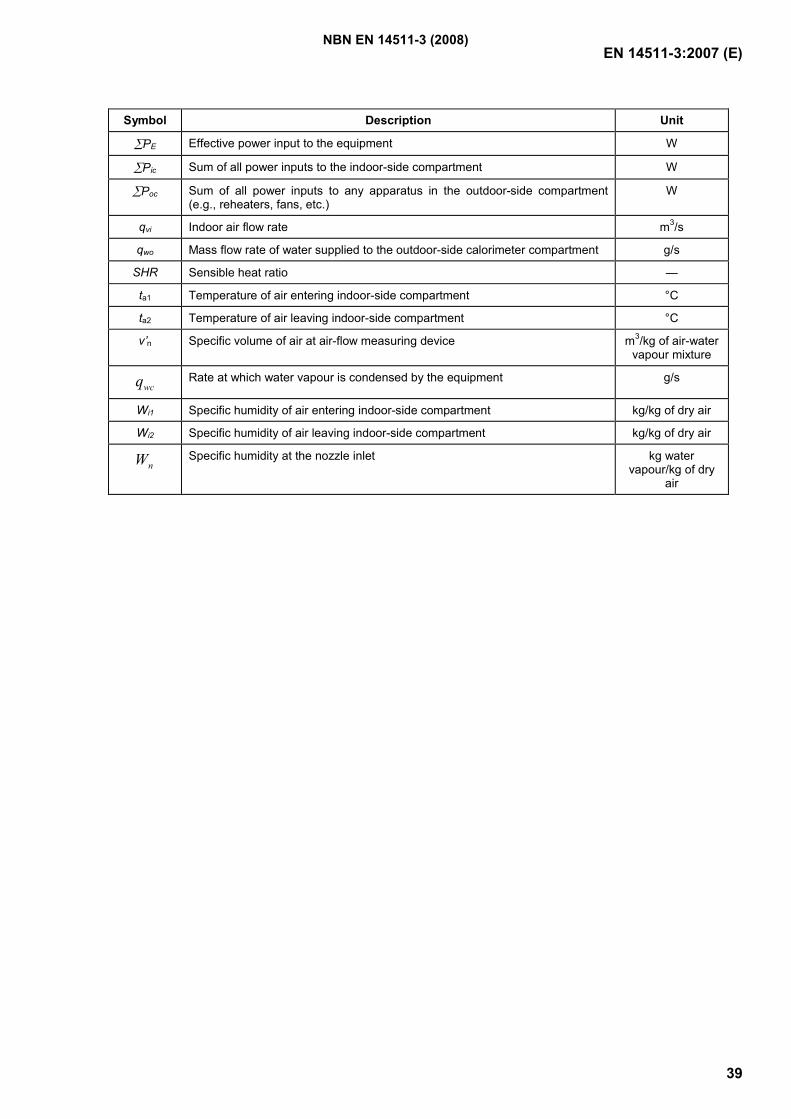
EN 14511-3:2007 (E)
39
Symbol Description Unit
∑PE Effective power input to the equipment W
∑Pic Sum of all power inputs to the indoor-side compartment W
∑Poc Sum of all power inputs to any apparatus in the outdoor-side compartment (e.g., reheaters, fans, etc.)
W
qvi Indoor air flow rate m3/s
qwo Mass flow rate of water supplied to the outdoor-side calorimeter compartment g/s
SHR Sensible heat ratio —
ta1 Temperature of air entering indoor-side compartment °C
ta2 Temperature of air leaving indoor-side compartment °C
v’n Specific volume of air at air-flow measuring device m3/kg of air-water vapour mixture
wcq Rate at which water vapour is condensed by the equipment g/s
Wi1 Specific humidity of air entering indoor-side compartment kg/kg of dry air
Wi2 Specific humidity of air leaving indoor-side compartment kg/kg of dry air
nW Specific humidity at the nozzle inlet kg water vapour/kg of dry
air
NBN EN 14511-3 (2008)
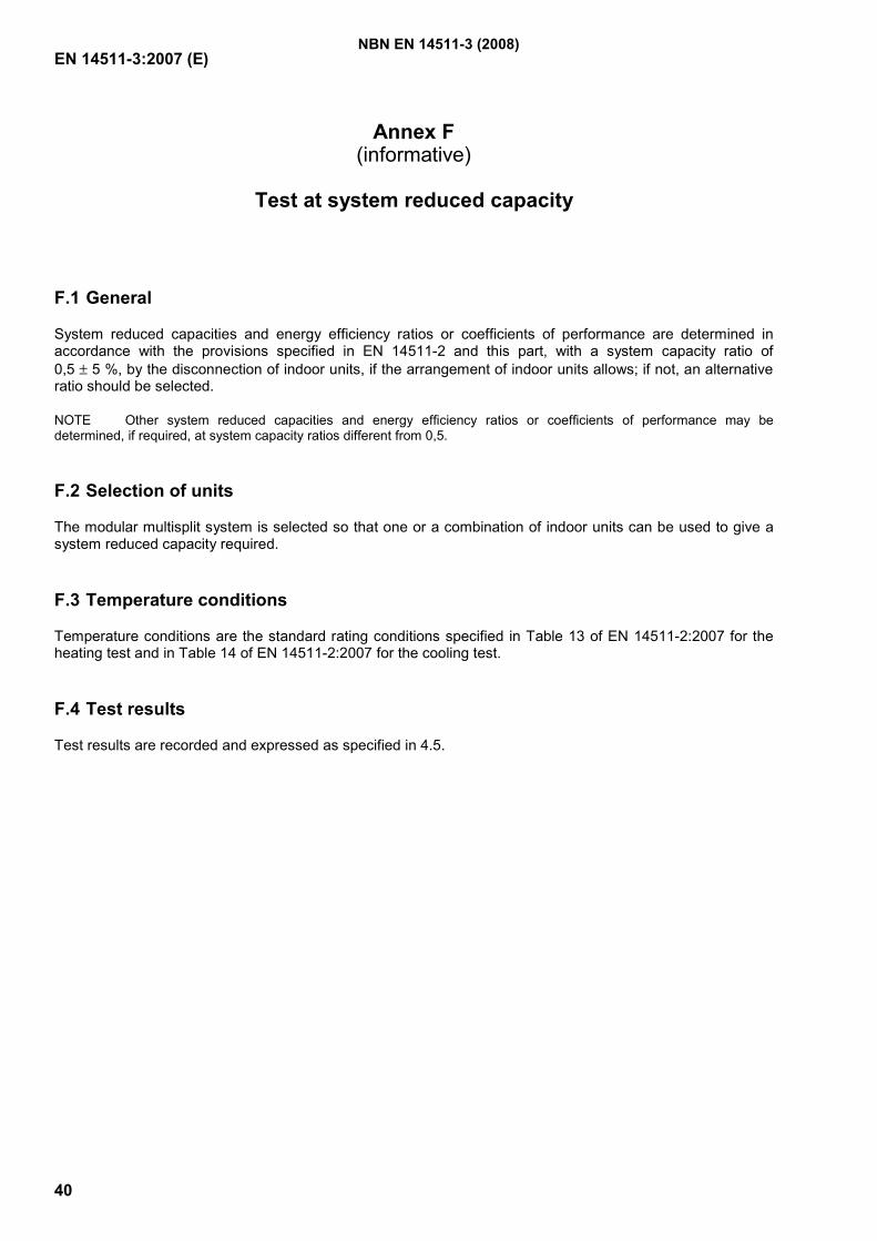
EN 14511-3:2007 (E)
40
Annex F (informative)
Test at system reduced capacity
F.1 General
System reduced capacities and energy efficiency ratios or coefficients of performance are determined in accordance with the provisions specified in EN 14511-2 and this part, with a system capacity ratio of 0,5 ± 5 %, by the disconnection of indoor units, if the arrangement of indoor units allows; if not, an alternative ratio should be selected.
NOTE Other system reduced capacities and energy efficiency ratios or coefficients of performance may be determined, if required, at system capacity ratios different from 0,5.
F.2 Selection of units
The modular multisplit system is selected so that one or a combination of indoor units can be used to give a system reduced capacity required.
F.3 Temperature conditions
Temperature conditions are the standard rating conditions specified in Table 13 of EN 14511-2:2007 for the heating test and in Table 14 of EN 14511-2:2007 for the cooling test.
F.4 Test results
Test results are recorded and expressed as specified in 4.5.
NBN EN 14511-3 (2008)
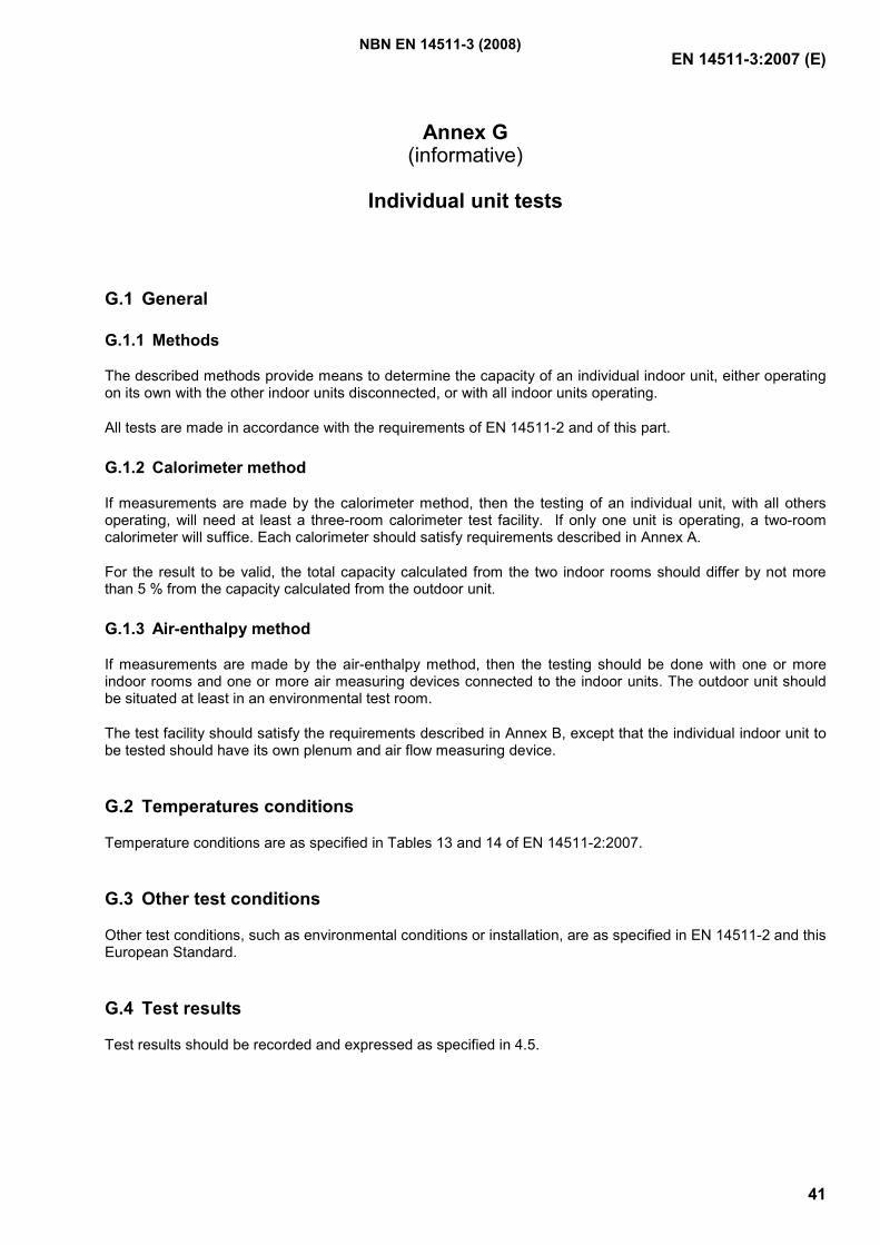
EN 14511-3:2007 (E)
41
Annex G (informative)
Individual unit tests
G.1 General
G.1.1 Methods
The described methods provide means to determine the capacity of an individual indoor unit, either operating on its own with the other indoor units disconnected, or with all indoor units operating.
All tests are made in accordance with the requirements of EN 14511-2 and of this part.
G.1.2 Calorimeter method
If measurements are made by the calorimeter method, then the testing of an individual unit, with all others operating, will need at least a three-room calorimeter test facility. If only one unit is operating, a two-room calorimeter will suffice. Each calorimeter should satisfy requirements described in Annex A.
For the result to be valid, the total capacity calculated from the two indoor rooms should differ by not more than 5 % from the capacity calculated from the outdoor unit.
G.1.3 Air-enthalpy method
If measurements are made by the air-enthalpy method, then the testing should be done with one or more indoor rooms and one or more air measuring devices connected to the indoor units. The outdoor unit should be situated at least in an environmental test room.
The test facility should satisfy the requirements described in Annex B, except that the individual indoor unit to be tested should have its own plenum and air flow measuring device.
G.2 Temperatures conditions
Temperature conditions are as specified in Tables 13 and 14 of EN 14511-2:2007.
G.3 Other test conditions
Other test conditions, such as environmental conditions or installation, are as specified in EN 14511-2 and this European Standard.
G.4 Test results
Test results should be recorded and expressed as specified in 4.5.
NBN EN 14511-3 (2008)

EN 14511-3:2007 (E)
42
G.5 Published results
Results should state if the units not being tested are disconnected or running during the test.
NBN EN 14511-3 (2008)
EN 14511-3:2007 (E)
43
Bibliography
[1] CEN/TS 14825, Air conditioners, liquid chilling packages and heat pumps with electrically driven compressors for space heating and cooling – Testing and rating at part load conditions
[2] EN ISO 5167-1, Measurement of fluid flow by means of pressure differential devices inserted in circular cross-section conduits running full – Part 1: General principles and requirements (ISO 5167-1:2003)
[3] ISO 5221, Air distribution and air diffusion – Rules to methods of measuring air flow rate in an air handling duct
NBN EN 14511-3 (2008)
GeregistreerdeBelgische norm
NBN EN 14511-4
Luchtbehandelingsapparatuur, koeleenheden met vloeistof enwarmtepompen met elektrisch aangedreven compressoren voorruimteverwarming en voor koeling - Deel 4: EisenClimatiseurs, groupes refroidisseurs de liquide et pompes à chaleur avec compresseur entraîné par moteurélectrique pour le chauffage et la réfrigération des locaux - Partie 4 : Exigences
2e uitg., mei 2008
Normklasse: D 40
Air conditioners, liquid chilling packages and heat pumps with electrically driven compressors for spaceheating and cooling - Part 4: Requirements
Prijsgroep: 12
Toelating tot publicatie: 29 januari 2008
Vervangt NBN EN 14511-4 (2004).
Deze Europese norm EN 14511-4:2008 heeft de status van een Belgische norm.
Deze Europese norm bestaat in drie officiële versies (Duits, Engels, Frans).
© NBN 2008
ICS: 23.120
Bureau voor Normalisatie Brabançonnelaan 29 B-1000 Brussel BelgiëTel: +32 2 738 01 12 - Fax: +32 2 733 42 64 - E-mail: [email protected] - NBN Online: www.nbn.beBank 000-3255621-10 IBAN BE41 0003 2556 2110 BIC BPOT BEB1 BTW: BE 0880.857.592
ICS: 23.120
norme belgeenregistrée
NBN EN 14511-4
Climatiseurs, groupes refroidisseurs de liquide et pompes à chaleuravec compresseur entraîné par moteur électrique pour le chauffage et laréfrigération des locaux - Partie 4 : ExigencesLuchtbehandelingsapparatuur, koeleenheden met vloeistof en warmtepompen met elektrisch aangedrevencompressoren voor ruimteverwarming en voor koeling - Deel 4: Eisen
2e éd., mai 2008
Indice de classement: D 40
Air conditioners, liquid chilling packages and heat pumps with electrically driven compressors for spaceheating and cooling - Part 4: Requirements
Autorisation de publication: 29 janvier 2008
Remplace NBN EN 14511-4 (2004).
La présente norme européenne EN 14511-4:2008 a le statut d'une norme belge.
La présente norme européenne existe en trois versions officielles (allemand, anglais, français).
Prix: groupe 12© NBN 2008
Bureau de Normalisation - Avenue de la Brabançonne 29 - 1000 Bruxelles - BelgiqueTél: +32 2 738 01 12 - Fax: +32 2 733 42 64 - E-mail: [email protected] - NBN Online: www.nbn.beBanque 000-3255621-10 IBAN BE41 0003 2556 2110 BIC BPOT BEB1 TVA: BE 0880.857.592

EUROPEAN STANDARD
NORME EUROPÉENNE
EUROPÄISCHE NORM
EN 14511-4
November 2007
ICS 23.120 Supersedes EN 14511-4:2004
English Version
Air conditioners, liquid chilling packages and heat pumps withelectrically driven compressors for space heating and cooling -
Part 4: Requirements
Climatiseurs, groupes refroidisseurs de liquide et pompes àchaleur avec compresseur entraîné par moteur électriquepour le chauffage et la réfrigération des locaux - Partie 4 :
Exigences
Luftkonditionierer, Flüssigkeitskühlsätze undWärmepumpen mit elektrisch angetriebenen Verdichtern
für die Raumbeheizung und Kühlung - Teil 4:Anforderungen
This European Standard was approved by CEN on 13 October 2007.
CEN members are bound to comply with the CEN/CENELEC Internal Regulations which stipulate the conditions for giving this EuropeanStandard the status of a national standard without any alteration. Up-to-date lists and bibliographical references concerning such nationalstandards may be obtained on application to the CEN Management Centre or to any CEN member.
This European Standard exists in three official versions (English, French, German). A version in any other language made by translationunder the responsibility of a CEN member into its own language and notified to the CEN Management Centre has the same status as theofficial versions.
CEN members are the national standards bodies of Austria, Belgium, Bulgaria, Cyprus, Czech Republic, Denmark, Estonia, Finland,France, Germany, Greece, Hungary, Iceland, Ireland, Italy, Latvia, Lithuania, Luxembourg, Malta, Netherlands, Norway, Poland, Portugal,Romania, Slovakia, Slovenia, Spain, Sweden, Switzerland and United Kingdom.
EUROPEAN COMMITTEE FOR STANDARDIZATIONC OM ITÉ EUR OP ÉEN DE NOR M ALIS AT IONEUROPÄISCHES KOMITEE FÜR NORMUNG
Management Centre: rue de Stassart, 36 B-1050 Brussels
© 2007 CEN All rights of exploitation in any form and by any means reservedworldwide for CEN national Members.
Ref. No. EN 14511-4:2007: E
NBN EN 14511-4 (2008)
EN 14511-4:2007 (E)
2
Contents Page
Foreword..............................................................................................................................................................3 1 Scope ......................................................................................................................................................4 2 Normative references ............................................................................................................................4 3 Terms and definitions ...........................................................................................................................5 4 Requirements .........................................................................................................................................5 4.1 General....................................................................................................................................................5 4.2 Temperature operating range...............................................................................................................5 4.3 Outside the operating range.................................................................................................................7 4.4 Shutting off the heat transfer medium flows ......................................................................................7 4.5 Complete power supply failure ............................................................................................................8 4.6 Condensate draining and enclosure sweat test .................................................................................8 4.7 Defrosting ...............................................................................................................................................9 4.8 Other requirements................................................................................................................................9 5 Marking ...................................................................................................................................................9 6 Technical data sheet ...........................................................................................................................10 6.1 General description .............................................................................................................................10 6.2 Performance characteristics ..............................................................................................................10 6.3 Electrical characteristics ....................................................................................................................11 6.4 Operating range ...................................................................................................................................11 7 Instructions ..........................................................................................................................................11 7.1 General..................................................................................................................................................11 7.2 Physical description............................................................................................................................11 7.3 Instructions for installation ................................................................................................................12 7.4 Instruction for maintenance ...............................................................................................................12 Bibliography ......................................................................................................................................................13
NBN EN 14511-4 (2008)
EN 14511-4:2007 (E)
3
Foreword
This document (EN 14511-4:2007) has been prepared by Technical Committee CEN/TC 113 “Heat pumps and air conditioning units”, the secretariat of which is held by AENOR.
This European Standard shall be given the status of a national standard, either by publication of an identical text or by endorsement, at the latest by May 2008, and conflicting national standards shall be withdrawn at the latest by May 2008.
Attention is drawn to the possibility that some of the elements of this document may be the subject of patent rights. CEN shall not be held responsible for identifying any or all such patent rights.
This document supersedes EN 14511-4:2004.
EN 14511 comprises the following parts under the general title "Air conditioners, liquid chilling packages and heat pumps with electrically driven compressors for space heating and cooling“:
- Part 1: Terms and definitions
- Part 2: Test conditions
- Part 3: Test methods
- Part 4: Requirements
According to the CEN/CENELEC Internal Regulations, the national standards organizations of the following countries are bound to implement this European Standard: Austria, Belgium, Bulgaria, Cyprus, Czech Republic, Denmark, Estonia, Finland, France, Germany, Greece, Hungary, Iceland, Ireland, Italy, Latvia, Lithuania, Luxembourg, Malta, Netherlands, Norway, Poland, Portugal, Romania, Slovakia, Slovenia, Spain, Sweden, Switzerland and the United Kingdom.
NBN EN 14511-4 (2008)
EN 14511-4:2007 (E)
4
1 Scope
This part of EN 14511 specifies minimum requirements which ensure that air conditioners, heat pumps and liquid chilling packages with electrical driven compressors are fit for the use designated by the manufacturer when used for space heating and/or cooling.
This European Standard applies to factory-made units that can be ducted.
This standard applies to factory-made liquid chilling packages with integral condensers or for use with remote condensers.
This standard applies to factory-made units of either fixed capacity or variable capacity by any means.
Packaged units, single split and multisplit systems are covered by this standard. Single duct and double duct units are covered by the standard.
In the case of units consisting of several parts, the standard applies only to those designed and supplied as a complete package, except for liquid chilling packages with remote condenser.
This standard is primarily intended for water and brine chilling packages but can be used for cooling any other liquid subject to agreement.
This standard applies to air-to-air air conditioners which evaporate the condensate on the condenser side.
The units having their condenser cooled by air and by the evaporation of external additional water are not covered by this standard.
This standard does not apply to units using transcritical cycles, e.g. with CO2 as refrigerant.
Installations used for heating and/or cooling of industrial processes are not within the scope of this standard.
NOTE Part load testing of units is dealt with in CEN/TS 14825.
2 Normative references
The following referenced documents are indispensable for the application of this document. For dated references, only the edition cited applies. For undated references, the latest edition of the referenced document (including any amendments) applies.
ENV 12102, Air conditioners, heat pumps and dehumidifiers with electrically driven compressors – Measurement of airborne noise – Determination of the sound power level
EN 14511-1:2007, Air conditioners, liquid chilling packages and heat pumps with electrically driven compressors for space heating and cooling – Part 1: Terms and definitions
EN 14511-2:2007, Air conditioners, liquid chilling packages and heat pumps with electrically driven compressors for space heating and cooling – Part 2: Test conditions
EN 14511-3:2007, Air conditioners, liquid chilling packages and heat pumps with electrically driven compressors for space heating and cooling – Part 3: Test methods
EN 60204-1, Safety of machinery - Electrical equipment of machines - Part 1: General requirements (IEC 60204-1:2005, modified)
EN 60335-2-40, Household and similar electrical appliances - Safety - Part 2-40: Particular requirements for electrical heat pumps, air-conditioners and dehumidifiers (IEC 60335-2-40:2002, modified)
NBN EN 14511-4 (2008)
EN 14511-4:2007 (E)
5
EN 61000-3-11, Electromagnetic compatibility (EMC) – Part 3-11: Limits; Limitation of voltage changes, voltage fluctuations and flicker in public low-voltage supply system; Equipment with rated current ≤ 75 A and subject to conditional connection (IEC 61000-3-11:2000)
3 Terms and definitions
For the purposes of this document, the terms and definitions given in EN 14511-1:2007 apply.
4 Requirements
4.1 General
Except where otherwise stated, tests shall be conducted as described in EN 14511-2 and EN 14511-3.
4.2 Temperature operating range
4.2.1 Starting test
The unit shall be capable of operating within the limit of use indicated by the manufacturer.
For every condition stated in Table 1, and for both cooling and heating mode where applicable, the unit shall start up and operate for at least 20 min, without being stopped by the safety devices.
Table 1 — Operational requirements conditions
Type Temperature at outdoor heat
exchanger ºC
Temperature at indoor heat exchanger
°C
Voltage V
All types Upper limit of use Upper limit of use Rated voltage
All types Lower limit of use Lower limit of use Rated voltage
The temperatures are set at the beginning of the test and maintained constant during the test.
Test voltage shall be as specified in Table 1. It is set at the beginning of the test and maintained constant during the test.
The environmental conditions during the test shall be as specified in Tables 1 and 2 of EN 14511-2:2007.
The flow rates shall be the same as that used for rating capacity test, as specified in EN 14511-2.
Deviation between individual values and set values shall be between:
zero and minus twice the permissible deviation according to Table 2 of EN 14511-3:2007, for the upper limit of use;
zero and plus twice the permissible deviation according to Table 2 of EN 14511-3:2007, for the lower limit of use.
Uncertainty of measurement shall be as specified in Table 1 of EN 14511-3:2007.
NBN EN 14511-4 (2008)
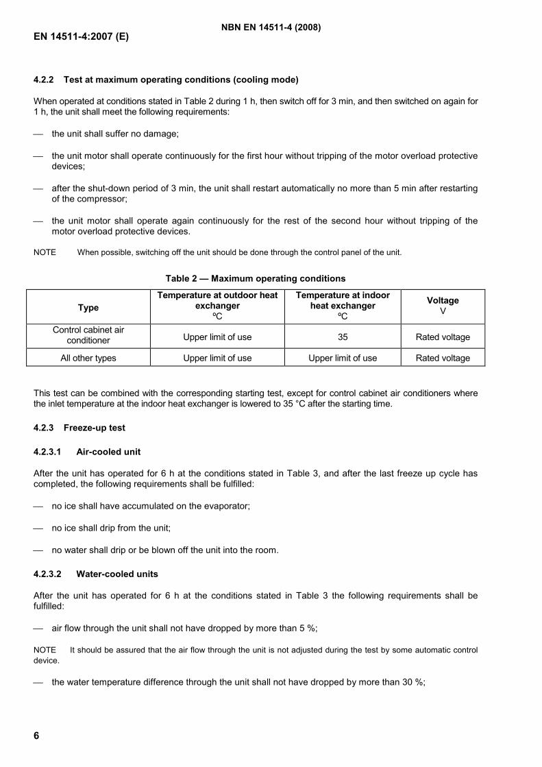
EN 14511-4:2007 (E)
6
4.2.2 Test at maximum operating conditions (cooling mode)
When operated at conditions stated in Table 2 during 1 h, then switch off for 3 min, and then switched on again for 1 h, the unit shall meet the following requirements:
the unit shall suffer no damage;
the unit motor shall operate continuously for the first hour without tripping of the motor overload protective devices;
after the shut-down period of 3 min, the unit shall restart automatically no more than 5 min after restarting of the compressor;
the unit motor shall operate again continuously for the rest of the second hour without tripping of the motor overload protective devices.
NOTE When possible, switching off the unit should be done through the control panel of the unit.
Table 2 — Maximum operating conditions
Type Temperature at outdoor heat
exchanger ºC
Temperature at indoor heat exchanger
ºC
Voltage V
Control cabinet air conditioner Upper limit of use 35 Rated voltage
All other types Upper limit of use Upper limit of use Rated voltage
This test can be combined with the corresponding starting test, except for control cabinet air conditioners where the inlet temperature at the indoor heat exchanger is lowered to 35 °C after the starting time.
4.2.3 Freeze-up test
4.2.3.1 Air-cooled unit
After the unit has operated for 6 h at the conditions stated in Table 3, and after the last freeze up cycle has completed, the following requirements shall be fulfilled:
no ice shall have accumulated on the evaporator;
no ice shall drip from the unit;
no water shall drip or be blown off the unit into the room.
4.2.3.2 Water-cooled units
After the unit has operated for 6 h at the conditions stated in Table 3 the following requirements shall be fulfilled:
air flow through the unit shall not have dropped by more than 5 %;
NOTE It should be assured that the air flow through the unit is not adjusted during the test by some automatic control device.
the water temperature difference through the unit shall not have dropped by more than 30 %;
NBN EN 14511-4 (2008)
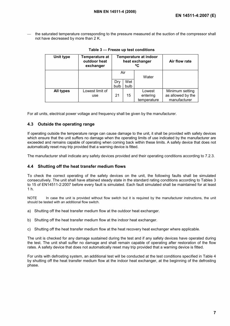
EN 14511-4:2007 (E)
7
the saturated temperature corresponding to the pressure measured at the suction of the compressor shall not have decreased by more than 2 K.
Table 3 — Freeze up test conditions
Unit type Temperature at outdoor heat
exchanger
Temperature at indoor heat exchanger
ºC
Air flow rate
Air
Dry bulb
Wet bulb
Water
All types Lowest limit of use
21
15
Lowest entering
temperature
Minimum setting as allowed by the
manufacturer
For all units, electrical power voltage and frequency shall be given by the manufacturer.
4.3 Outside the operating range
If operating outside the temperature range can cause damage to the unit, it shall be provided with safety devices which ensure that the unit suffers no damage when the operating limits of use indicated by the manufacturer are exceeded and remains capable of operating when coming back within these limits. A safety device that does not automatically reset may trip provided that a warning device is fitted.
The manufacturer shall indicate any safety devices provided and their operating conditions according to 7.2.3.
4.4 Shutting off the heat transfer medium flows
To check the correct operating of the safety devices on the unit, the following faults shall be simulated consecutively. The unit shall have attained steady state in the standard rating conditions according to Tables 3 to 15 of EN14511-2:2007 before every fault is simulated. Each fault simulated shall be maintained for at least 1 h.
NOTE In case the unit is provided without flow switch but it is required by the manufacturer instructions, the unit should be tested with an additional flow switch.
a) Shutting off the heat transfer medium flow at the outdoor heat exchanger.
b) Shutting off the heat transfer medium flow at the indoor heat exchanger.
c) Shutting off the heat transfer medium flow at the heat recovery heat exchanger where applicable.
The unit is checked for any damage sustained during the test and if any safety devices have operated during the test. The unit shall suffer no damage and shall remain capable of operating after restoration of the flow rates. A safety device that does not automatically reset may trip provided that a warning device is fitted.
For units with defrosting system, an additional test will be conducted at the test conditions specified in Table 4 by shutting off the heat transfer medium flow at the indoor heat exchanger, at the beginning of the defrosting phase.
NBN EN 14511-4 (2008)
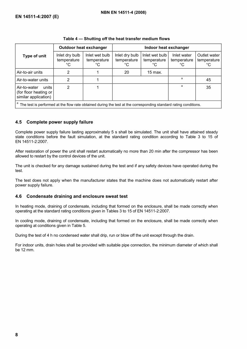
EN 14511-4:2007 (E)
8
Table 4 — Shutting off the heat transfer medium flows
Outdoor heat exchanger Indoor heat exchanger
Type of unit Inlet dry bulb temperature
°C
Inlet wet bulb temperature
°C
Inlet dry bulb temperature
°C
Inlet wet bulb temperature
°C
Inlet water temperature
°C
Outlet water temperature
°C
Air-to-air units 2 1 20 15 max.
Air-to-water units 2 1 a 45
Air-to-water units (for floor heating or similar application)
2 1 a 35
a The test is performed at the flow rate obtained during the test at the corresponding standard rating conditions.
4.5 Complete power supply failure
Complete power supply failure lasting approximately 5 s shall be simulated. The unit shall have attained steady state conditions before the fault simulation, at the standard rating condition according to Table 3 to 15 of EN 14511-2:2007.
After restoration of power the unit shall restart automatically no more than 20 min after the compressor has been allowed to restart by the control devices of the unit.
The unit is checked for any damage sustained during the test and if any safety devices have operated during the test.
The test does not apply when the manufacturer states that the machine does not automatically restart after power supply failure.
4.6 Condensate draining and enclosure sweat test
In heating mode, draining of condensate, including that formed on the enclosure, shall be made correctly when operating at the standard rating conditions given in Tables 3 to 15 of EN 14511-2:2007.
In cooling mode, draining of condensate, including that formed on the enclosure, shall be made correctly when operating at conditions given in Table 5.
During the test of 4 h no condensed water shall drip, run or blow off the unit except through the drain.
For indoor units, drain holes shall be provided with suitable pipe connection, the minimum diameter of which shall be 12 mm.
NBN EN 14511-4 (2008)
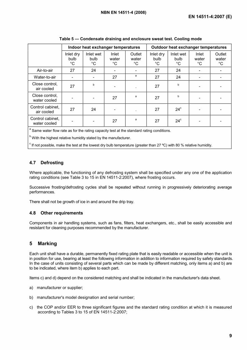
EN 14511-4:2007 (E)
9
Table 5 — Condensate draining and enclosure sweat test. Cooling mode
Indoor heat exchanger temperatures Outdoor heat exchanger temperatures Inlet dry
bulb °C
Inlet wet bulb °C
Inlet water
°C
Outlet water
°C
Inlet dry bulb °C
Inlet wet bulb °C
Inlet water
°C
Outlet water
°C Air-to-air 27 24 - - 27 24 - -
Water-to-air - - 27 a 27 24 - - Close control,
air cooled 27 b - - 27 b - -
Close control, water cooled - - 27 a 27 b - -
Control cabinet, air cooled 27 24 - - 27 24c - -
Control cabinet, water cooled - - 27 a
27 24c - -
a Same water flow rate as for the rating capacity test at the standard rating conditions. b With the highest relative humidity stated by the manufacturer. c If not possible, make the test at the lowest dry bulb temperature (greater than 27 ºC) with 80 % relative humidity.
4.7 Defrosting
Where applicable, the functioning of any defrosting system shall be specified under any one of the application rating conditions (see Table 3 to 15 in EN 14511-2:2007), where frosting occurs.
Successive frosting/defrosting cycles shall be repeated without running in progressively deteriorating average performances.
There shall not be growth of ice in and around the drip tray.
4.8 Other requirements
Components in air handling systems, such as fans, filters, heat exchangers, etc., shall be easily accessible and resistant for cleaning purposes recommended by the manufacturer.
5 Marking
Each unit shall have a durable, permanently fixed rating plate that is easily readable or accessible when the unit is in position for use, bearing at least the following information in addition to information required by safety standards. In the case of units consisting of several parts which can be made by different matching, only items a) and b) are to be indicated, where item b) applies to each part.
Items c) and d) depend on the considered matching and shall be indicated in the manufacturer's data sheet.
a) manufacturer or supplier;
b) manufacturer's model designation and serial number;
c) the COP and/or EER to three significant figures and the standard rating condition at which it is measured according to Tables 3 to 15 of EN 14511-2:2007;
NBN EN 14511-4 (2008)
EN 14511-4:2007 (E)
10
d) heating/cooling capacity in kilowatts, with two digits after the decimal comma but not more than 3 significant figures at the test condition given in item c) of Clause 5.
e) for control cabinet air conditioners, the sensible cooling capacity in kilowatts, with one digit after the decimal comma but not more than 3 significant figures at the test condition given in item c) of Clause 5.
Further information may be provided; with regard to rating only the other rating conditions given in Tables 3 to 15 of EN 14511-2:2007 are to be used.
6 Technical data sheet
6.1 General description
The manufacturer shall provide the following information:
trade mark, model designation;
power supply (voltage, frequency);
denomination of the unit (e.g.: air-to-water);
intended use of the unit (e.g.: control cabinet air conditioner);
number of separate component units;
type and mass of refrigerant charge;
overall dimensions and weight of each separate component unit.
6.2 Performance characteristics
6.2.1 Rating characteristics
The manufacturer shall provide in a table or as a graph the rating characteristics according to EN 14511-2 and EN 14511-3.
Rating characteristics include:
the cooling capacity, the effective power input, the EER and the SHR (where applicable);
the heating capacity, the effective power input and the COP (where applicable);
the heat recovery capacity and the type of liquid (where applicable).
The manufacturer shall state that the characteristics apply to a new unit with clean heat exchangers.
6.2.2 Additional characteristics
In addition, the manufacturer shall provide the following characteristics for the rated point(s):
non ducted air-to-air units: flow rates or rotational speeds of fans;
non ducted air-to-water units: air flow rate or rotational speed of fan; water flow rate and pressure difference;
NBN EN 14511-4 (2008)
EN 14511-4:2007 (E)
11
unit intended to discharge into double floor: nominal flow rate and external static pressure difference;
other types of units: nominal flow rates and external static pressure differences for air and water.
6.2.3 Sound characteristics
The manufacturer shall provide the sound power level and the corresponding test method according to ENV 12102.
6.3 Electrical characteristics
The manufacturer shall specify the electrical characteristics in accordance with EN 60335-2-40 or EN 60204-1 as applicable and:
maximum starting current of the unit, as defined in EN 61000-3-11;
total power input and current at the rated point, excluding the starting period;
reactive power or power factor at the rated point, for units with a total power input greater than 10 kW;
power input of fan and pump if included in the units.
6.4 Operating range
The manufacturer shall specify:
limits of use (temperatures and flows);
whether there are devices fitted which do not allow the unit to operate when these limits are exceeded.
7 Instructions
7.1 General
If not already required by other standards, the manufacturer shall provide the information as described.
7.2 Physical description
7.2.1 Refrigerant, air and/or liquid circuits
The manufacturer shall:
specify the refrigerant, air and liquid circuits preferably providing circuit diagrams, showing every functional unit, control and safety device and specifying their type;
if the unit uses water in the heat exchangers specify the water capacity contained in the unit, and specify either the constructional materials of the heat exchangers or the water quality;
if used, specify the type of brine and the concentration into any other liquid;
specify the type of oil to be used in the compressor.
NBN EN 14511-4 (2008)
EN 14511-4:2007 (E)
12
7.2.2 Additional heating devices, when integral to the unit
The manufacturer shall specify the type and location of additional heating devices and their control and safety devices.
7.2.3 Control and safety
The manufacturer shall:
state the functions achieved by the control and safety devices provided with the unit and specify when applicable their provision for adjustment and the method by which the safety devices are reset;
provide specifications for any control or safety devices necessary to ensure correct operation of the unit but which are not provided with the unit;
specify any limitation to the use of the rest of the installation.
7.3 Instructions for installation
The manufacturer shall specify in particular:
the required location conditions (whether units are to be installed outside or in a weather proof enclosure, or in a heated space);
requirements of physical layout, access and clearance;
requirements for the electrical, liquid, air and refrigerant connections, to be made on site;
the location of warning and tripping devices;
the installation precautions to be taken to ensure, in particular:
correct circulation of the heat transfer media;
water draining;
cleanliness of heat exchange surfaces;
to minimise noise, vibration or other adverse effects.
Special indications for units using soil, sea water, ground water or surface water: specify any materials which are in contact with the water or with the brine.
7.4 Instruction for maintenance
The manufacturer shall state:
content and frequency of routine maintenance operations to be performed by the user;
content and frequency of maintenance and inspection operations which shall be performed by a specialist.
NBN EN 14511-4 (2008)
EN 14511-4:2007 (E)
13
Bibliography
[1] CEN/TS 14825, Air conditioners, liquid chilling packages and heat pumps with electrically driven compressors for space heating and cooling – Testing and rating at part load conditions
NBN EN 14511-4 (2008)