Embed Size (px)
Citation preview

Centre Scientifique et Technique du Bâtiment 84 avenue Jean Jaurès CHAMPS-SUR-MARNE F-77447 Marne-la-Vallée Cedex 2 Tél. : (33) 01 64 68 82 82 Fax : (33) 01 60 05 70 37
Autorisé etnotifié conformément à
l’article 10 de la directive89/106/EEC du Conseil, du
21 décembre 1988, relative aurapprochement des dispositions
législatives, réglementaireset administratives des Etats
membres concernantles produits deconstruction.
MEMBRE DE L’EOTA
European Technical Approval ETA-09/0056 (English language translation, the original version is in French language)
Nom commercial :
Trade name: FM753 Crack
Titulaire :
Holder of approval: FRIULSIDER
Via Trieste,1
I 33048 San Giovanni al Natisone (UDINE)
ITALIE
Type générique et utilisation prévue du produit de construction :
Cheville métallique à expansion par vissage à couple contrôlé en acier électrozingué, pour fixation dans le béton: diamètres M8, M10, M12 et M16.
Generic type and use of
construction product:
Torque-controlled expansion anchor, made of galvanised
steel, for use in concrete: sizes M8, M10, M12 and M16.
Validité du : au :
Validity from / to:
03/01/2012
10/04/2014
Usine de fabrication :
Manufacturing plant: Plant 1
Le présent Agrément technique européen contient :
This European Technical Approval
contains:
14 pages incluant 7 annexes faisant partie intégrante du document.
14 pages including 7 annexes which form an integral part of
the document.
Cet Agrément Technique Européen remplace l’Agrément ETA-09/0056 valable du 10/04/2009 to 10/04/2014
This European Technical Approval replaces ETA-09/0056 with validity from 10/04/2009 to 10/04/2014
Organisation pour l’Agrément Technique Européen
European Organisation for Technical Approvals

Page 2 of European Technical Approval ETA-09/0056 issued on 03/01/2012 English translation prepared by CSTB
I LEGAL BASES AND GENERAL CONDITIONS
1. This European Technical Approval is issued by the Centre Scientifique et Technique du Bâtiment in accordance with:
Council Directive 89/106/EEC of 21 December 1988 on the approximation of laws, regulations and administrative provisions of Member States relating to construction products
1, modified by the Council Directive 93/68/EEC of 22 July 1993
2;
Décret n° 92-647 du 8 juillet 19923 concernant l’aptitude à l’usage des produits de
construction;
Common Procedural Rules for Requesting, Preparing and the Granting of European Technical Approvals
set out in the Annex of Commission Decision 94/23/EC
4;
Guideline for European Technical Approval of « Metal Anchors for use in Concrete » ETAG 001, edition 1997, Part 1 « Anchors in general » and Part 2 « Torque-controlled expansion anchors ».
2. The Centre Scientifique et Technique du Bâtiment is authorised to check whether the provisions of this European Technical Approval are met. Checking may take place in the manufacturing plant (for example concerning the fulfilment of assumptions made in this European Technical Approval with regard to manufacturing). Nevertheless, the responsibility for the conformity of the products with the European Technical Approval and for their fitness for the intended use remains with the holder of the European Technical Approval.
3. This European Technical Approval is not to be transferred to manufacturers or agents of manufacturer other than those indicated on page 1; or manufacturing plants other than those indicated on page 1 of this European Technical Approval.
4. This European Technical Approval may be withdrawn by the Centre Scientifique et Technique du Bâtiment pursuant to Article 5 (1) of the Council Directive 89/106/EEC.
5. Reproduction of this European Technical Approval including transmission by electronic means shall be in full. However, partial reproduction can be made with the written consent of the Centre Scientifique et Technique du Bâtiment. In this case partial reproduction has to be designated as such. Texts and drawings of advertising brochures shall not contradict or misuse the European Technical Approval.
6. The European Technical Approval is issued by the approval body in its official language. This version corresponds to the version circulated within EOTA. Translations into other languages have to be designated as such.
1 Official Journal of the European Communities n° L 40, 11.2.1989, p. 12
2 Official Journal of the European Communities n° L 220, 30.8.1993, p. 1
3 Journal officiel de la République française du 14 juillet 1992
4 Official Journal of the European Communities n° L 17, 20.1.1994, p. 34
Page 3 of European Technical Approval ETA-09/0056 issued on 03/01/2012 English translation prepared by CSTB
II SPECIFIC CONDITIONS OF THE EUROPEAN TECHNICAL APPROVAL
1 Definition of product and intended use
1.1. Definition of product
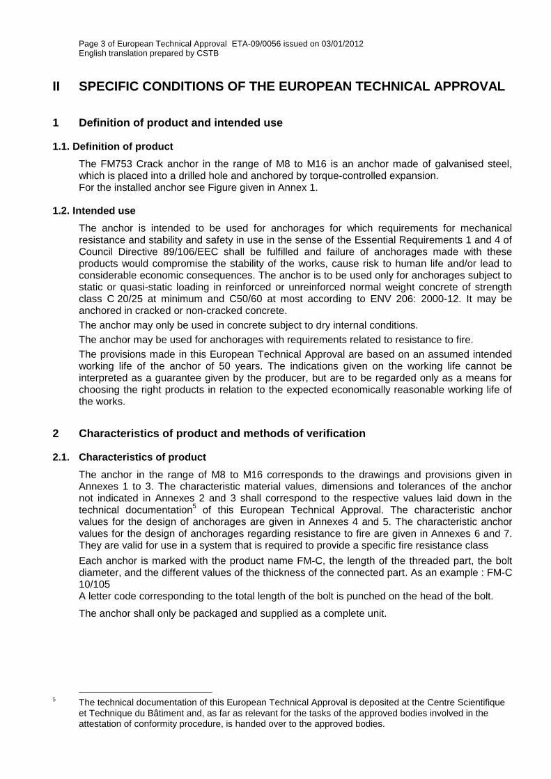
The FM753 Crack anchor in the range of M8 to M16 is an anchor made of galvanised steel, which is placed into a drilled hole and anchored by torque-controlled expansion. For the installed anchor see Figure given in Annex 1.
1.2. Intended use
The anchor is intended to be used for anchorages for which requirements for mechanical resistance and stability and safety in use in the sense of the Essential Requirements 1 and 4 of Council Directive 89/106/EEC shall be fulfilled and failure of anchorages made with these products would compromise the stability of the works, cause risk to human life and/or lead to considerable economic consequences. The anchor is to be used only for anchorages subject to static or quasi-static loading in reinforced or unreinforced normal weight concrete of strength class C 20/25 at minimum and C50/60 at most according to ENV 206: 2000-12. It may be anchored in cracked or non-cracked concrete.
The anchor may only be used in concrete subject to dry internal conditions.
The anchor may be used for anchorages with requirements related to resistance to fire.
The provisions made in this European Technical Approval are based on an assumed intended working life of the anchor of 50 years. The indications given on the working life cannot be interpreted as a guarantee given by the producer, but are to be regarded only as a means for choosing the right products in relation to the expected economically reasonable working life of the works.
2 Characteristics of product and methods of verification
2.1. Characteristics of product
The anchor in the range of M8 to M16 corresponds to the drawings and provisions given in Annexes 1 to 3. The characteristic material values, dimensions and tolerances of the anchor not indicated in Annexes 2 and 3 shall correspond to the respective values laid down in the technical documentation
5 of this European Technical Approval. The characteristic anchor
values for the design of anchorages are given in Annexes 4 and 5. The characteristic anchor values for the design of anchorages regarding resistance to fire are given in Annexes 6 and 7. They are valid for use in a system that is required to provide a specific fire resistance class
Each anchor is marked with the product name FM-C, the length of the threaded part, the bolt diameter, and the different values of the thickness of the connected part. As an example : FM-C 10/105 A letter code corresponding to the total length of the bolt is punched on the head of the bolt.
The anchor shall only be packaged and supplied as a complete unit.
5 The technical documentation of this European Technical Approval is deposited at the Centre Scientifique
et Technique du Bâtiment and, as far as relevant for the tasks of the approved bodies involved in the attestation of conformity procedure, is handed over to the approved bodies.

Page 4 of European Technical Approval ETA-09/0056 issued on 03/01/2012 English translation prepared by CSTB
2.2. Methods of verification
The assessment of fitness of the anchor for the intended use in relation to the requirements for mechanical resistance and stability and safety in use in the sense of the Essential Requirements 1 and 4 has been made in accordance with the « Guideline for European Technical Approval of Metal Anchors for use in Concrete », Part 1 « Anchors in general » and Part 2 « Torque-controlled expansion anchors », on the basis of Option 1.
The assessment of the anchor for the intended use in relation to the requirements for resistance to fire has been made in accordance with the Technical Report N°020 “Evaluation of anchorages in concrete concerning resistance to fire”.
In addition to the specific clauses relating to dangerous substances contained in this European technical approval, there may be other requirements applicable for the products falling within its scope (e.g. transposed European legislation and national laws, regulations and administratives provisions). In order to meet the provisions of the Construction Product Directive, these requirements need also to be complied with, when and where they apply.
3 Evaluation of Conformity and CE marking
3.1. Attestation of conformity system
The system of attestation of conformity 2 (i) (referred to as system 1) according to Council Directive 89/106/EEC Annex III laid down by the European Commission provides:
a) tasks for the manufacturer:
1. factory production control, 2. further testing of samples taken at the factory by the manufacturer in accordance
with a prescribed test plan.
b) tasks for the approved body:
3. initial type-testing of the product, 4. initial inspection of factory and of factory production control, 5. continuous surveillance, assessment and approval of factory production control.
3.2. Responsibilities
3.2.1. Tasks of the manufacturer, factory production control
The manufacturer has a factory production control system in the plant and exercises permanent internal control of production. All the elements, requirements and provisions adopted by the manufacturer are documented in a systematic manner in the form of written policies and procedures. This production control system ensures that the product is in conformity with the European Technical Approval.
The manufacturer shall only use raw materials supplied with the relevant inspection documents as laid down in the prescribed test plan
6. The incoming raw materials shall be subject to
controls and tests by the manufacturer before acceptance. Check of incoming materials such as nuts, washers, wire for bolts and metal band for expansion sleeves shall include control of the inspection documents presented by suppliers (comparison with nominal values) by verifying dimension and determining material properties, e.g. tensile strength, hardness, surface finish.
The manufactured components of the anchor shall be subjected to the following tests:
Dimensions of component parts: · bolt (diameters, lengths, thread, geometry of the cone, marking);
6 The prescribed test plan has been deposited at the Centre Scientifique et Technique du Bâtiment and is
only made available to the approved bodies involved in the conformity attestation procedure.
Page 5 of European Technical Approval ETA-09/0056 issued on 03/01/2012 English translation prepared by CSTB
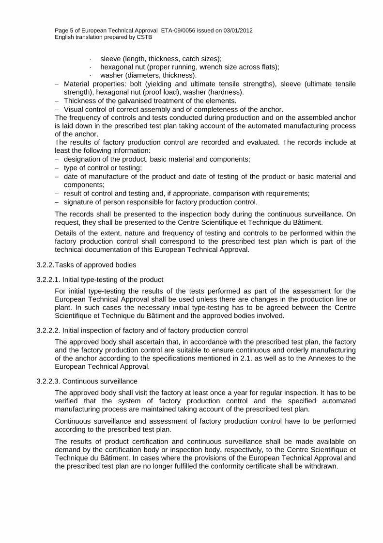
· sleeve (length, thickness, catch sizes); · hexagonal nut (proper running, wrench size across flats); · washer (diameters, thickness).
Material properties: bolt (yielding and ultimate tensile strengths), sleeve (ultimate tensile strength), hexagonal nut (proof load), washer (hardness).
Thickness of the galvanised treatment of the elements.
Visual control of correct assembly and of completeness of the anchor. The frequency of controls and tests conducted during production and on the assembled anchor is laid down in the prescribed test plan taking account of the automated manufacturing process of the anchor. The results of factory production control are recorded and evaluated. The records include at least the following information:
designation of the product, basic material and components;
type of control or testing;
date of manufacture of the product and date of testing of the product or basic material and components;
result of control and testing and, if appropriate, comparison with requirements;
signature of person responsible for factory production control.
The records shall be presented to the inspection body during the continuous surveillance. On request, they shall be presented to the Centre Scientifique et Technique du Bâtiment.
Details of the extent, nature and frequency of testing and controls to be performed within the factory production control shall correspond to the prescribed test plan which is part of the technical documentation of this European Technical Approval.
3.2.2. Tasks of approved bodies
3.2.2.1. Initial type-testing of the product
For initial type-testing the results of the tests performed as part of the assessment for the European Technical Approval shall be used unless there are changes in the production line or plant. In such cases the necessary initial type-testing has to be agreed between the Centre Scientifique et Technique du Bâtiment and the approved bodies involved.
3.2.2.2. Initial inspection of factory and of factory production control
The approved body shall ascertain that, in accordance with the prescribed test plan, the factory and the factory production control are suitable to ensure continuous and orderly manufacturing of the anchor according to the specifications mentioned in 2.1. as well as to the Annexes to the European Technical Approval.
3.2.2.3. Continuous surveillance
The approved body shall visit the factory at least once a year for regular inspection. It has to be verified that the system of factory production control and the specified automated manufacturing process are maintained taking account of the prescribed test plan.
Continuous surveillance and assessment of factory production control have to be performed according to the prescribed test plan.
The results of product certification and continuous surveillance shall be made available on demand by the certification body or inspection body, respectively, to the Centre Scientifique et Technique du Bâtiment. In cases where the provisions of the European Technical Approval and the prescribed test plan are no longer fulfilled the conformity certificate shall be withdrawn.
Page 6 of European Technical Approval ETA-09/0056 issued on 03/01/2012 English translation prepared by CSTB
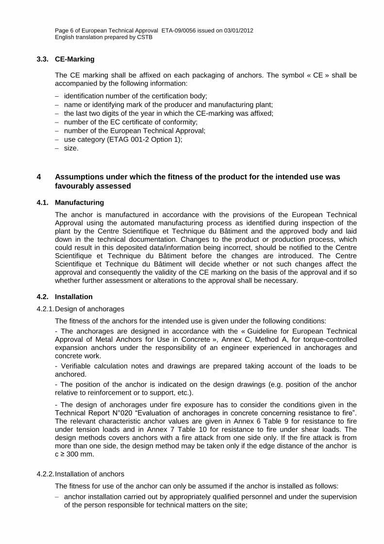
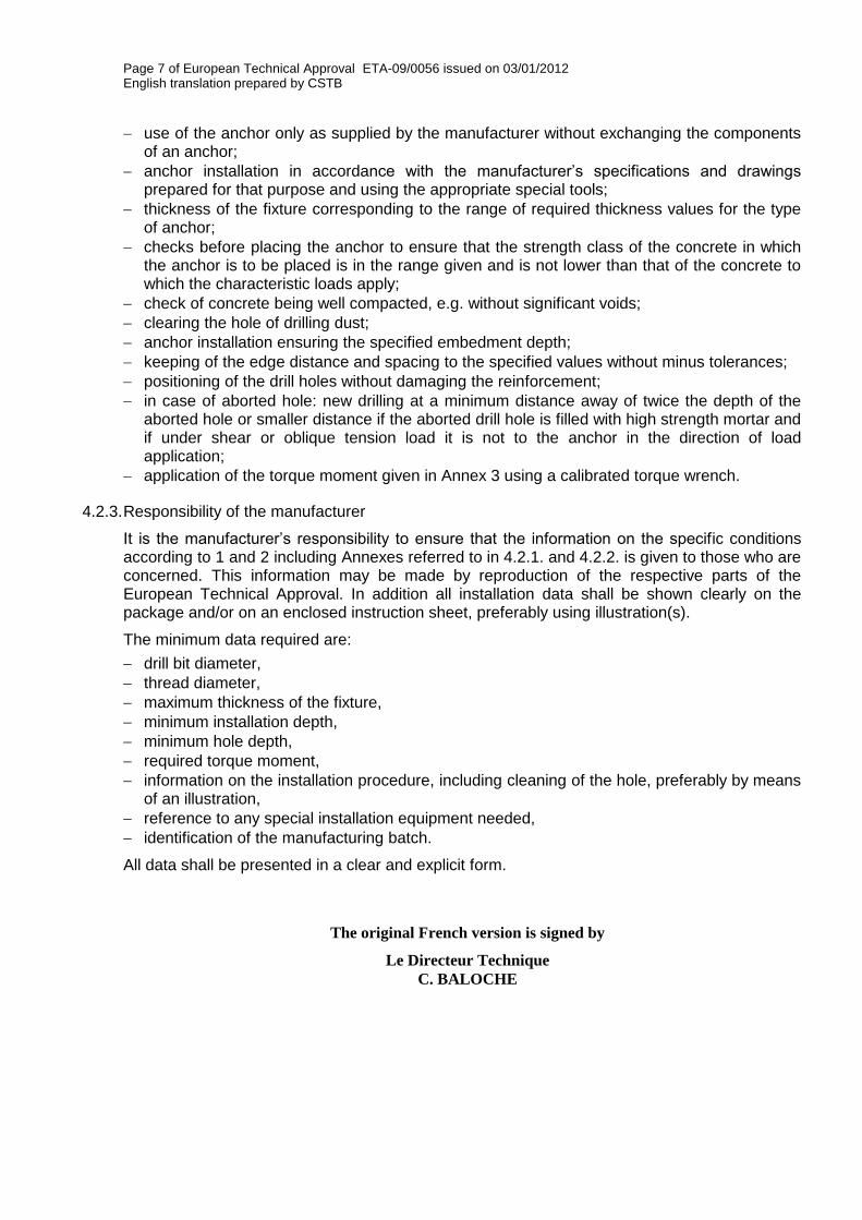
3.3. CE-Marking
The CE marking shall be affixed on each packaging of anchors. The symbol « CE » shall be accompanied by the following information:
identification number of the certification body;
name or identifying mark of the producer and manufacturing plant;
the last two digits of the year in which the CE-marking was affixed;
number of the EC certificate of conformity;
number of the European Technical Approval;
use category (ETAG 001-2 Option 1);
size.
4 Assumptions under which the fitness of the product for the intended use was
favourably assessed
4.1. Manufacturing
The anchor is manufactured in accordance with the provisions of the European Technical Approval using the automated manufacturing process as identified during inspection of the plant by the Centre Scientifique et Technique du Bâtiment and the approved body and laid down in the technical documentation. Changes to the product or production process, which could result in this deposited data/information being incorrect, should be notified to the Centre Scientifique et Technique du Bâtiment before the changes are introduced. The Centre Scientifique et Technique du Bâtiment will decide whether or not such changes affect the approval and consequently the validity of the CE marking on the basis of the approval and if so whether further assessment or alterations to the approval shall be necessary.
4.2. Installation
4.2.1. Design of anchorages
The fitness of the anchors for the intended use is given under the following conditions:
- The anchorages are designed in accordance with the « Guideline for European Technical Approval of Metal Anchors for Use in Concrete », Annex C, Method A, for torque-controlled expansion anchors under the responsibility of an engineer experienced in anchorages and concrete work.
- Verifiable calculation notes and drawings are prepared taking account of the loads to be anchored.
- The position of the anchor is indicated on the design drawings (e.g. position of the anchor relative to reinforcement or to support, etc.).
- The design of anchorages under fire exposure has to consider the conditions given in the Technical Report N°020 “Evaluation of anchorages in concrete concerning resistance to fire”. The relevant characteristic anchor values are given in Annex 6 Table 9 for resistance to fire under tension loads and in Annex 7 Table 10 for resistance to fire under shear loads. The design methods covers anchors with a fire attack from one side only. If the fire attack is from more than one side, the design method may be taken only if the edge distance of the anchor is c ≥ 300 mm.
4.2.2. Installation of anchors
The fitness for use of the anchor can only be assumed if the anchor is installed as follows:
anchor installation carried out by appropriately qualified personnel and under the supervision of the person responsible for technical matters on the site;
Page 7 of European Technical Approval ETA-09/0056 issued on 03/01/2012 English translation prepared by CSTB
use of the anchor only as supplied by the manufacturer without exchanging the components of an anchor;
anchor installation in accordance with the manufacturer’s specifications and drawings prepared for that purpose and using the appropriate special tools;
thickness of the fixture corresponding to the range of required thickness values for the type of anchor;
checks before placing the anchor to ensure that the strength class of the concrete in which the anchor is to be placed is in the range given and is not lower than that of the concrete to which the characteristic loads apply;
check of concrete being well compacted, e.g. without significant voids;
clearing the hole of drilling dust;
anchor installation ensuring the specified embedment depth;
keeping of the edge distance and spacing to the specified values without minus tolerances;
positioning of the drill holes without damaging the reinforcement;
in case of aborted hole: new drilling at a minimum distance away of twice the depth of the aborted hole or smaller distance if the aborted drill hole is filled with high strength mortar and if under shear or oblique tension load it is not to the anchor in the direction of load application;
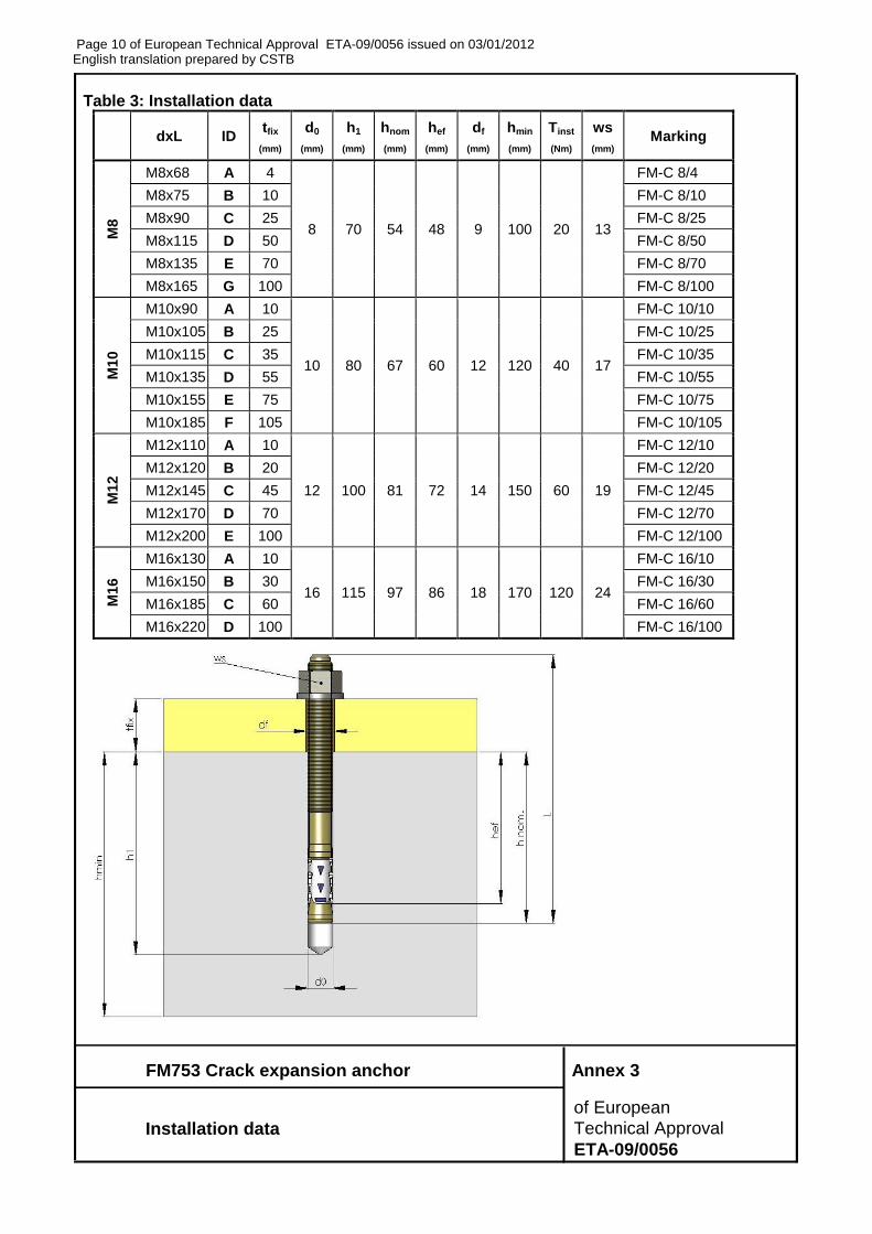
application of the torque moment given in Annex 3 using a calibrated torque wrench.
4.2.3. Responsibility of the manufacturer
It is the manufacturer’s responsibility to ensure that the information on the specific conditions according to 1 and 2 including Annexes referred to in 4.2.1. and 4.2.2. is given to those who are concerned. This information may be made by reproduction of the respective parts of the European Technical Approval. In addition all installation data shall be shown clearly on the package and/or on an enclosed instruction sheet, preferably using illustration(s).
The minimum data required are:
drill bit diameter,
thread diameter,
maximum thickness of the fixture,
minimum installation depth,
minimum hole depth,
required torque moment,
information on the installation procedure, including cleaning of the hole, preferably by means of an illustration,
reference to any special installation equipment needed,
identification of the manufacturing batch.
All data shall be presented in a clear and explicit form.
The original French version is signed by
Le Directeur Technique
C. BALOCHE
Page 8 of European Technical Approval ETA-09/0056 issued on 03/01/2012 English translation prepared by CSTB
FM753 Crack expansion anchor Annex 1
of European
Product and intended use Technical Approval
ETA-09/0056
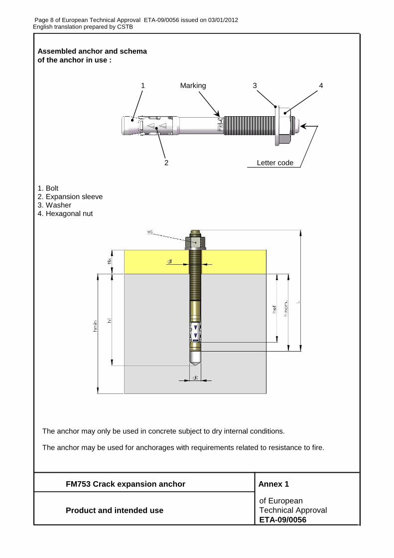
Assembled anchor and schema
of the anchor in use :
1 Marking 3 4
2 Letter code
1. Bolt 2. Expansion sleeve 3. Washer 4. Hexagonal nut
The anchor may only be used in concrete subject to dry internal conditions.
The anchor may be used for anchorages with requirements related to resistance to fire.
Page 9 of European Technical Approval ETA-09/0056 issued on 03/01/2012 English translation prepared by CSTB
FM753 Crack expansion anchor Annex 2
of European
Dimensions of anchors- Materials Technical Approval
ETA-09/0056
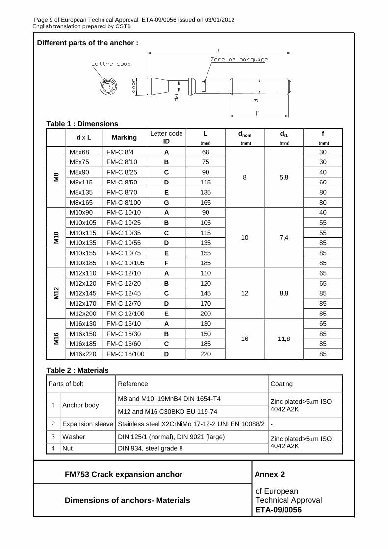
Different parts of the anchor :
Table 1 : Dimensions
d x L Marking Letter code
ID L
(mm)
dnom
(mm)
dr1
(mm)
f
(mm)
M8
M8x68 FM-C 8/4 A 68
8 5,8
30
M8x75 FM-C 8/10 B 75 30
M8x90 FM-C 8/25 C 90 40
M8x115 FM-C 8/50 D 115 60
M8x135 FM-C 8/70 E 135 80
M8x165 FM-C 8/100 G 165 80
M10
M10x90 FM-C 10/10 A 90
10 7,4
40
M10x105 FM-C 10/25 B 105 55
M10x115 FM-C 10/35 C 115 55
M10x135 FM-C 10/55 D 135 85
M10x155 FM-C 10/75 E 155 85
M10x185 FM-C 10/105 F 185 85
M12
M12x110 FM-C 12/10 A 110
12 8,8
65
M12x120 FM-C 12/20 B 120 65
M12x145 FM-C 12/45 C 145 85
M12x170 FM-C 12/70 D 170 85
M12x200 FM-C 12/100 E 200 85
M16
M16x130 FM-C 16/10 A 130
16 11,8
65
M16x150 FM-C 16/30 B 150 85
M16x185 FM-C 16/60 C 185 85
M16x220 FM-C 16/100 D 220 85
Table 2 : Materials
Parts of bolt Reference Coating
1 Anchor body M8 and M10: 19MnB4 DIN 1654-T4 Zinc plated>5m ISO
4042 A2K M12 and M16 C30BKD EU 119-74
2 Expansion sleeve Stainless steel X2CrNiMo 17-12-2 UNI EN 10088/2 -
3 Washer DIN 125/1 (normal), DIN 9021 (large) Zinc plated>5m ISO 4042 A2K
4 Nut DIN 934, steel grade 8
3
Page 10 of European Technical Approval ETA-09/0056 issued on 03/01/2012 English translation prepared by CSTB
FM753 Crack expansion anchor Annex 3
of European
Installation data Technical Approval
ETA-09/0056
Table 3: Installation data dxL ID
tfix
(mm)
d0
(mm)
h1
(mm)
hnom
(mm)
hef
(mm)
df
(mm)
hmin
(mm)
Tinst
(Nm)
ws
(mm) Marking
M8
M8x68 A 4
8 70 54 48 9 100 20 13
FM-C 8/4
M8x75 B 10 FM-C 8/10
M8x90 C 25 FM-C 8/25
M8x115 D 50 FM-C 8/50
M8x135 E 70 FM-C 8/70
M8x165 G 100 FM-C 8/100
M10
M10x90 A 10
10 80 67 60 12 120 40 17
FM-C 10/10
M10x105 B 25 FM-C 10/25
M10x115 C 35 FM-C 10/35
M10x135 D 55 FM-C 10/55
M10x155 E 75 FM-C 10/75
M10x185 F 105 FM-C 10/105
M12
M12x110 A 10
12 100 81 72 14 150 60 19
FM-C 12/10
M12x120 B 20 FM-C 12/20
M12x145 C 45 FM-C 12/45
M12x170 D 70 FM-C 12/70
M12x200 E 100 FM-C 12/100
M16
M16x130 A 10
16 115 97 86 18 170 120 24
FM-C 16/10
M16x150 B 30 FM-C 16/30
M16x185 C 60 FM-C 16/60
M16x220 D 100 FM-C 16/100
Page 11 of European Technical Approval ETA-09/0056 issued on 03/01/2012 English translation prepared by CSTB
FM753 Crack expansion anchor Annex 4
Design method A : characteristic values of of European
resistance to tension loads and displacements Technical Approval
ETA-09/0056
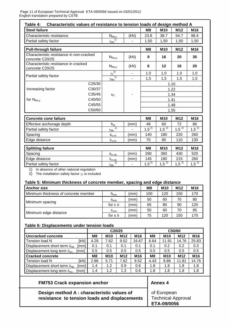
Table 4: Characteristic values of resistance to tension loads of design method A
Steel failure M8 M10 M12 M16
Characteristic resistance NRk,s (kN) 23.8 38.7 54.7 98.4
Partial safety factor Ms1)
- 1,50 1,50 1,50 1,50
Pull-through failure M8 M10 M12 M16
Characteristic resistance in non-cracked concrete C20/25
NRk,p (kN) 9 16 20 35
Characteristic resistance in cracked concrete C20/25
NRk,p (kN) 6 12 16 20
Partial safety factor 2
2) - 1.0 1.0 1.0 1.0
Mp1)
- 1,5 1,5 1,5 1,5
C25/30 1.10
Increasing factor C30/37 1.22
C35/45 c - 1.34
for NRk,p C40/50 1.41
C45/55 1.48
C50/60 1.55
Concrete cone failure M8 M10 M12 M16
Effective anchorage depth hef (mm) 48 60 72 86
Partial safety factor Mc 1)
- 1,5 2)
1,5 2)
1,5 2)
1,5 2)
Spacing scr,N (mm) 140 180 220 260
Edge distance ccr,N (mm) 70 90 110 130
Splitting failure M8 M10 M12 M16
Spacing scr,sp (mm) 290 360 430 520
Edge distance ccr,sp (mm) 145 180 215 260
Partial safety factor Mc 1)
- 1,5 2)
1,5 2)
1,5 2)
1,5 2)
1) In absence of other national regulation
2) The installation safety factor 2 is included
Table 5: Minimum thickness of concrete member, spacing and edge distance
Anchor size M8 M10 M12 M16
Minimum thickness of concrete member hmin (mm) 100 120 150 170
Minimum spacing smin (mm) 50 60 70 80
for c ≥ (mm) 65 80 90 120
Minimum edge distance cmin (mm) 50 60 70 85
for s ≥ (mm) 75 120 150 170
Table 6: Displacements under tension loads
C20/25 C50/60
Uncracked concrete M8 M10 M12 M16 M8 M10 M12 M16
Tension load N [kN] 4.29 7.62 9.52 16.67 6.64 11.91 14.76 25.83
Displacement short term N0 [mm] 0.1 0.1 0.1 0.1 0.1 0.2 0.2 0.3
Displacement long term N [mm] 0.5 0.5 0.5 0.5 0.5 0.5 0.5 0.5
Cracked concrete M8 M10 M12 M16 M8 M10 M12 M16
Tension load N [kN] 2.86 5.71 7.62 9.52 4.43 8.86 11.81 14.76
Displacement short term N0 [mm] 1.4 1.2 0.9 0.6 1.8 1.8 1.8 1.8
Displacement long term N [mm] 1.4 1.2 1.3 0.6 1.8 1.8 1.8 1.8
Page 12 of European Technical Approval ETA-09/0056 issued on 03/01/2012 English translation prepared by CSTB
FM753 Crack expansion anchor Annex 5
Design method A : characteristic values of of European
resistance to shear loads and displacements Technical Approval
ETA-09/0056
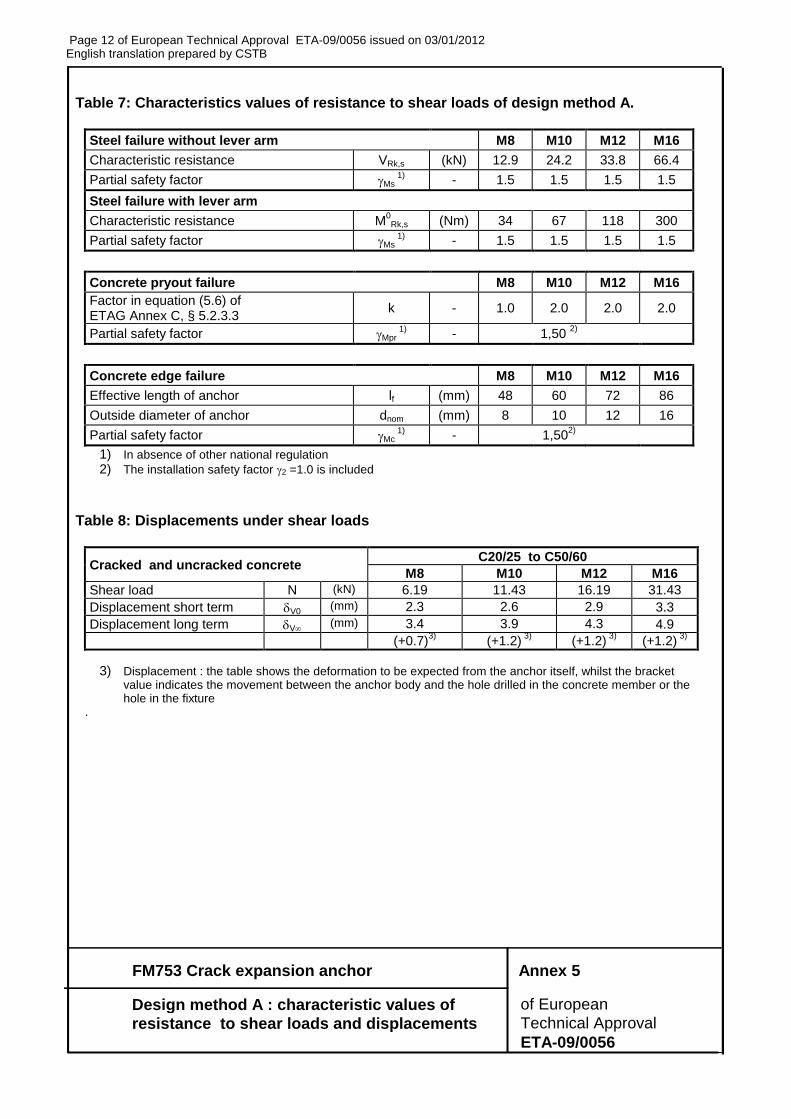
Table 7: Characteristics values of resistance to shear loads of design method A.
Steel failure without lever arm M8 M10 M12 M16
Characteristic resistance VRk,s (kN) 12.9 24.2 33.8 66.4
Partial safety factor Ms 1)
- 1.5 1.5 1.5 1.5
Steel failure with lever arm
Characteristic resistance M0Rk,s (Nm) 34 67 118 300
Partial safety factor Ms 1)
- 1.5 1.5 1.5 1.5
Concrete pryout failure M8 M10 M12 M16
Factor in equation (5.6) of ETAG Annex C, § 5.2.3.3
k - 1.0 2.0 2.0 2.0
Partial safety factor Mpr 1)
- 1,50 2)
Concrete edge failure M8 M10 M12 M16
Effective length of anchor lf (mm) 48 60 72 86
Outside diameter of anchor dnom (mm) 8 10 12 16
Partial safety factor Mc 1)
- 1,502)
1) In absence of other national regulation
2) The installation safety factor 2 =1.0 is included
Table 8: Displacements under shear loads
Cracked and uncracked concrete C20/25 to C50/60
M8 M10 M12 M16
Shear load N (kN) 6.19 11.43 16.19 31.43
Displacement short term V0 (mm) 2.3 2.6 2.9 3.3
Displacement long term V (mm) 3.4 3.9 4.3 4.9
(+0.7)3)
(+1.2) 3)
(+1.2) 3)
(+1.2) 3)
3) Displacement : the table shows the deformation to be expected from the anchor itself, whilst the bracket value indicates the movement between the anchor body and the hole drilled in the concrete member or the hole in the fixture
.
Page 13 of European Technical Approval ETA-09/0056 issued on 03/01/2012 English translation prepared by CSTB
FM753 Crack expansion anchor Annex 6
Design method A : Characteristic values of tension of European
load under fire exposure Technical Approval
ETA-09/0056
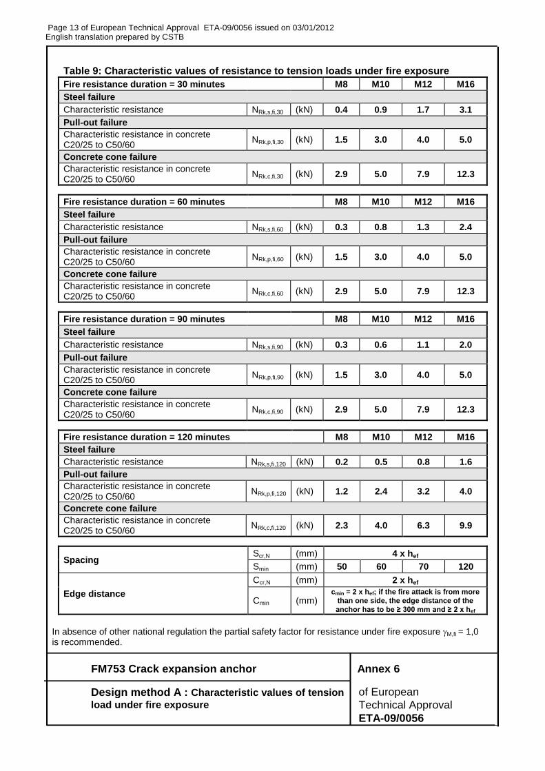
Table 9: Characteristic values of resistance to tension loads under fire exposure
Fire resistance duration = 30 minutes M8 M10 M12 M16
Steel failure
Characteristic resistance NRk,s,fi,30 (kN) 0.4 0.9 1.7 3.1
Pull-out failure
Characteristic resistance in concrete C20/25 to C50/60
NRk,p,fi,30 (kN) 1.5 3.0 4.0 5.0
Concrete cone failure
Characteristic resistance in concrete C20/25 to C50/60
NRk,c,fi,30 (kN) 2.9 5.0 7.9 12.3
Fire resistance duration = 60 minutes M8 M10 M12 M16
Steel failure
Characteristic resistance NRk,s,fi,60 (kN) 0.3 0.8 1.3 2.4
Pull-out failure
Characteristic resistance in concrete C20/25 to C50/60
NRk,p,fi,60 (kN) 1.5 3.0 4.0 5.0
Concrete cone failure
Characteristic resistance in concrete C20/25 to C50/60
NRk,c,fi,60 (kN) 2.9 5.0 7.9 12.3
Fire resistance duration = 90 minutes M8 M10 M12 M16
Steel failure
Characteristic resistance NRk,s,fi,90 (kN) 0.3 0.6 1.1 2.0
Pull-out failure
Characteristic resistance in concrete C20/25 to C50/60
NRk,p,fi,90 (kN) 1.5 3.0 4.0 5.0
Concrete cone failure
Characteristic resistance in concrete C20/25 to C50/60
NRk,c,fi,90 (kN) 2.9 5.0 7.9 12.3
Fire resistance duration = 120 minutes M8 M10 M12 M16
Steel failure
Characteristic resistance NRk,s,fi,120 (kN) 0.2 0.5 0.8 1.6
Pull-out failure
Characteristic resistance in concrete C20/25 to C50/60
NRk,p,fi,120 (kN) 1.2 2.4 3.2 4.0
Concrete cone failure
Characteristic resistance in concrete C20/25 to C50/60
NRk,c,fi,120 (kN) 2.3 4.0 6.3 9.9
Spacing Scr,N (mm) 4 x hef
Smin (mm) 50 60 70 120
Edge distance
Ccr,N (mm) 2 x hef
Cmin (mm) cmin = 2 x hef; if the fire attack is from more
than one side, the edge distance of the
anchor has to be ≥ 300 mm and ≥ 2 x hef
In absence of other national regulation the partial safety factor for resistance under fire exposure M,fi = 1,0 is recommended.
Page 14 of European Technical Approval ETA-09/0056 issued on 03/01/2012 English translation prepared by CSTB
FM753 Crack expansion anchor Annex 7
Design method A : Characteristic values of shear of European
load under fire exposure Technical Approval
ETA-09/0056
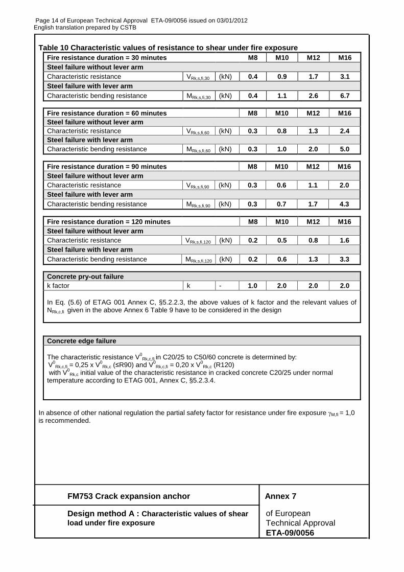
Table 10 Characteristic values of resistance to shear under fire exposure
Fire resistance duration = 30 minutes M8 M10 M12 M16
Steel failure without lever arm
Characteristic resistance VRk,s,fi,30 (kN) 0.4 0.9 1.7 3.1
Steel failure with lever arm
Characteristic bending resistance MRk,s,fi,30 (kN) 0.4 1.1 2.6 6.7
Fire resistance duration = 60 minutes M8 M10 M12 M16
Steel failure without lever arm
Characteristic resistance VRk,s,fi,60 (kN) 0.3 0.8 1.3 2.4
Steel failure with lever arm
Characteristic bending resistance MRk,s,fi,60 (kN) 0.3 1.0 2.0 5.0
Fire resistance duration = 90 minutes M8 M10 M12 M16
Steel failure without lever arm
Characteristic resistance VRk,s,fi,90 (kN) 0.3 0.6 1.1 2.0
Steel failure with lever arm
Characteristic bending resistance MRk,s,fi,90 (kN) 0.3 0.7 1.7 4.3
Fire resistance duration = 120 minutes M8 M10 M12 M16
Steel failure without lever arm
Characteristic resistance VRk,s,fi,120 (kN) 0.2 0.5 0.8 1.6
Steel failure with lever arm
Characteristic bending resistance MRk,s,fi,120 (kN) 0.2 0.6 1.3 3.3
Concrete pry-out failure
k factor k - 1.0 2.0 2.0 2.0
In Eq. (5.6) of ETAG 001 Annex C, §5.2.2.3, the above values of k factor and the relevant values of NRk,c,fi given in the above Annex 6 Table 9 have to be considered in the design
Concrete edge failure
The characteristic resistance V
0Rk,c,fi in C20/25 to C50/60 concrete is determined by:
V0Rk,c,fi = 0,25 x V
0Rk,c (≤R90) and V
0Rk,c,fi = 0,20 x V
0Rk,c (R120)
with V0Rk,c initial value of the characteristic resistance in cracked concrete C20/25 under normal
temperature according to ETAG 001, Annex C, §5.2.3.4.
In absence of other national regulation the partial safety factor for resistance under fire exposure M,fi = 1,0 is recommended.