Embed Size (px)
Citation preview
Centre Scientifique et Technique du Bâtiment 84 avenue Jean Jaurès Champs sur Marne F-77447 Marne-la-Vallée Cedex 2 Tél. : (33) 01 64 68 82 82 Fax : (33) 01 60 05 70 37
Autorisé etnotifié conformément à
l’article 10 de la directive89/106/EEC du Conseil, du
21 décembre 1988, relative aurapprochement des dispositions
législatives, réglementaireset administratives des Etats
membres concernantles produits deconstruction.
MEMBRE DE L’EOTA
European Technical Approval ETA- 13/0437 (English language translation, the original version is in French language)
Nom commercial : Trade name:
SPIT MULTI-MAX
Titulaire : Holder of approval:
Société SPIT Route de Lyon F-26501 BOURG-LES-VALENCE France
Type générique et utilisation prévue du produit de construction :
Cheville à scellement de type "à injection" avec tige d’ancrage diamètres M8, M10, M12, pour fixation dans les maçonneries.
Generic type and use of construction product:
Bonded injection type anchor with anchor rod sizes M8, M10, M12 for use in masonry.
Validité du : au : Validity from / to:
31/05/2013 31/05/2018
Usine de fabrication : Manufacturing plant:
Société SPIT Route de Lyon F-26501 BOURG-LES-VALENCE France
Le présent Agrément technique européen contient : This European Technical Approval contains:
18 pages incluant 11 annexes faisant partie intégrante du document. 18 pages including 11 annexes which form an integral part of the document.
Organisation pour l’Agrément Technique Européen
European Organisation for Technical Approvals
Page 2 of European Technical Approval ETA-13/0437 issued on 31/05/2013 English translation prepared by CSTB
I LEGAL BASES AND GENERAL CONDITIONS
1. This European Technical Approval is issued by the Centre Scientifique et Technique du Bâtiment in accordance with:
Council Directive 89/106/EEC of 21 December 1988 on the approximation of laws, regulations and administrative provisions of Member States relating to construction products1, modified by the Council Directive 93/68/EEC of 22 July 19932; and Regulation (EC) N° 1882/2003 of the European Parliament and of the Council 3;
Décret n° 92-647 du 8 juillet 19924 concernant l’aptitude à l’usage des produits de construction; Common Procedural Rules for Requesting, Preparing and the Granting of European Technical
Approvals set out in the Annex of Commission Decision 94/23/EC5; Guideline for European Technical Approval of « Metal Injection Anchors for use in Masonry »
ETAG 029, edition 2012. 2. The Centre Scientifique et Technique du Bâtiment is authorised to check whether the provisions
of this European Technical Approval are met. Checking may take place in the manufacturing plant (for example concerning the fulfilment of assumptions made in this European Technical Approval with regard to manufacturing). Nevertheless, the responsibility for the conformity of the products with the European Technical Approval and for their fitness for the intended use remains with the holder of the European Technical Approval.
3. This European Technical Approval is not to be transferred to manufacturers or agents of manufacturer other than those indicated on page 1; or manufacturing plants other than those indicated on page 1 of this European Technical Approval.
4. This European Technical Approval may be withdrawn by the Centre Scientifique et Technique du Bâtiment pursuant to Article 5 (1) of the Council Directive 89/106/EEC.
5. Reproduction of this European Technical Approval including transmission by electronic means shall be in full. However, partial reproduction can be made with the written consent of the Centre Scientifique et Technique du Bâtiment. In this case partial reproduction has to be designated as such. Texts and drawings of advertising brochures shall not contradict or misuse the European Technical Approval.
6. The European Technical Approval is issued by the approval body in its official language. This version corresponds to the version circulated within EOTA. Translations into other languages have to be designated as such.
1 Official Journal of the European Communities n° L 40, 11.2.1989, p. 12 2 Official Journal of the European Communities n° L 220, 30.8.1993, p. 1 3 Official Journal of the European Union n° L 284, 31.10.2003, p. 25 4 Journal officiel de la République française du 14 juillet 1992 5 Official Journal of the European Communities n° L 17, 20.1.1994, p. 34
Page 3 of European Technical Approval ETA-13/0437 issued on 31/05/2013 English translation prepared by CSTB
II SPECIFIC CONDITIONS OF THE EUROPEAN TECHNICAL APPROVAL
1 Definition of product and intended use
1.1. Definition of product
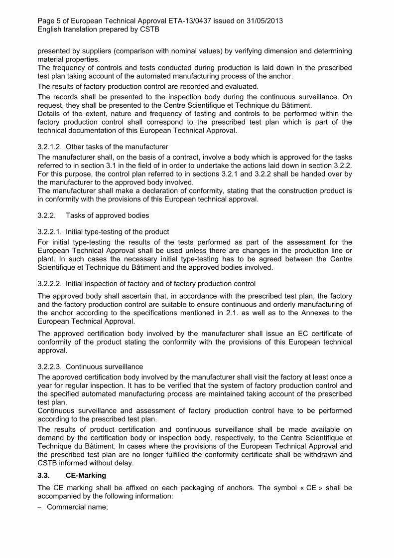
The SPIT MULTI-MAX is a bonded anchor (injection type) with anchor rod made of galvanised steel or stainless steel which is placed into a drilled hole previously injected with a two components injection mortar using an applicator gun equipped with a special mixing nozzle. The anchor rod is inserted into the resin with a slow and slight twisting motion. The mortar cartridges are available in different sizes 410 ml to 280 ml The SPIT MULTI-MAX is intended to be used in masonry
For the installed anchor see Figure given in Annex 2.
1.2. Intended use
The anchor is intended to be used for anchorages for which requirements for mechanical resistance and stability and safety in use in the sense of the Essential Requirements 1 and 4 of Council Directive 89/106/EEC shall be fulfilled and failure of anchorages made with these products would compromise the stability of the works, cause risk to human life and/or lead to considerable economic consequences. The anchor is to be used only for anchorages subject to static or quasi-static loading in solid masonry (use category b) or in hollow or perforated masonry (use category c) according to annexe 6 and 7. The mortar strength class of the masonry has to be M 2,5 according to EN 998-2:2010 at minimum. The anchor may be used in dry or wet structure (category w/w).
The anchor may be used in the following temperature ranges :
Temperature range :-40°C to +40°C
(max short term temperature +40°C and max long term temperature +24°C)
Element made of zinc coated steel:
The element made of eclectroplated steel may only be used in structures subject to dry internal conditions.
Element made of stainless steel:
The element made of stainless steel may be used in structures subject to dry internal conditions and also in concrete subject to external atmospheric exposure (including industrial and marine environment), or exposure in permanently damp internal conditions, if no particular aggressive conditions exist. Such particular aggressive conditions are e.g. permanent, alternating immersion in seawater or the splash zone of seawater, chloride atmosphere of indoor swimming pools or atmosphere with extreme chemical pollution (e.g. in desulphurization plants or road tunnels where de-icing materials are used).
The provisions made in this European Technical Approval are based on an assumed intended working life of the anchor of 50 years. The indications given on the working life cannot be interpreted as a guarantee given by the producer, but are to be regarded only as a means for choosing the right products in relation to the expected economically reasonable working life of the works.
2 Characteristics of product and methods of verification
2.1. Characteristics of product
The anchor and the mortar cartridges correspond to the drawings and provisions given in the annexes. The characteristic material values, dimensions and tolerances of the anchor not indicated in the annexes shall correspond to the respective values laid down in the technical
Page 4 of European Technical Approval ETA-13/0437 issued on 31/05/2013 English translation prepared by CSTB
documentation6 of this European Technical Approval. The characteristic anchor values for the design of anchorages are given in Annexes 9 to 11. The metal parts of the injection anchor are assumed to satisfy the requirement of class A1 of the characteristic reaction to fire in accordance with the provisions of EC decision 96/603/EC, amended by 2000/605/EC. Regarding resistance to fire no performance is determined
2.2. Methods of verification
The assessment of fitness of the anchor for the intended use in relation to the requirements for mechanical resistance and stability and safety in use in the sense of the Essential Requirements 1 and 4 has been made in accordance with the « Guideline for European Technical Approval of Metal Injection Anchors for use in Masonry », ETAG029, based on the use categories b and c in respect of the base material and category w/w in respect of installation and use.
In addition to the specific clauses relating to dangerous substances contained in this European Technical Approval, there may be other requirements applicable to the products falling within its scope (e.g. transposed European legislation and national laws, regulations and administrative provisions). In order to meet the provisions of the UE Construction Products Directive, these requirements need also to be complied with, when and where they apply.
3 Evaluation of Conformity and CE marking
3.1. Attestation of conformity system
According to the decision 97/177/EC of the European Commision7 System 1 of the attestation of conformity applies. This system of attestation of conformity is defined as follows: System 1: Certification of conformity of the product by an approved certification body on the basis of: a) tasks for the manufacturer:
1. factory production control, 2. further testing of samples taken at the factory by the manufacturer in accordance with a prescribed test plan.
b) tasks for the approved body: 3. initial type-testing of the product, 4. initial inspection of factory and of factory production control, 5. continuous surveillance, assessment and approval of factory production control.
3.2. Responsibilities
3.2.1. Tasks of the manufacturer
3.2.1.1. Factory production control
The manufacturer shall have a factory production control system in the plant and shall exercise permanent internal control of production. All the elements, requirements and provisions adopted by the manufacturer are documented in a systematic manner in the form of written policies and procedures. This production control system ensures that the product is in conformity with the European Technical Approval.
The manufacturer shall only use raw materials supplied with the relevant inspection documents as laid down in the prescribed test plan8. The incoming raw materials shall be subject to controls and tests by the manufacturer before acceptance. Check of incoming materials such as nuts, washers, threaded rods, resin, hardeners… shall include control of the inspection documents
6 The technical documentation of this European Technical Approval is deposited at the Centre Scientifique et Technique du Bâtiment and, as far as relevant for the tasks of the approved bodies involved in the attestation of conformity procedure, is handed over to the approved bodies. 7 Official Journal of the European Communities L 073 of 14.03.1997 8 The prescribed test plan has been deposited at the Centre Scientifique et Technique du Bâtiment and is only made available to the approved bodies involved in the conformity attestation procedure.
Page 5 of European Technical Approval ETA-13/0437 issued on 31/05/2013 English translation prepared by CSTB
presented by suppliers (comparison with nominal values) by verifying dimension and determining material properties. The frequency of controls and tests conducted during production is laid down in the prescribed test plan taking account of the automated manufacturing process of the anchor.
The results of factory production control are recorded and evaluated.
The records shall be presented to the inspection body during the continuous surveillance. On request, they shall be presented to the Centre Scientifique et Technique du Bâtiment. Details of the extent, nature and frequency of testing and controls to be performed within the factory production control shall correspond to the prescribed test plan which is part of the technical documentation of this European Technical Approval.
3.2.1.2. Other tasks of the manufacturer
The manufacturer shall, on the basis of a contract, involve a body which is approved for the tasks referred to in section 3.1 in the field of in order to undertake the actions laid down in section 3.2.2. For this purpose, the control plan referred to in sections 3.2.1 and 3.2.2 shall be handed over by the manufacturer to the approved body involved. The manufacturer shall make a declaration of conformity, stating that the construction product is in conformity with the provisions of this European technical approval.
3.2.2. Tasks of approved bodies
3.2.2.1. Initial type-testing of the product
For initial type-testing the results of the tests performed as part of the assessment for the European Technical Approval shall be used unless there are changes in the production line or plant. In such cases the necessary initial type-testing has to be agreed between the Centre Scientifique et Technique du Bâtiment and the approved bodies involved.
3.2.2.2. Initial inspection of factory and of factory production control
The approved body shall ascertain that, in accordance with the prescribed test plan, the factory and the factory production control are suitable to ensure continuous and orderly manufacturing of the anchor according to the specifications mentioned in 2.1. as well as to the Annexes to the European Technical Approval.
The approved certification body involved by the manufacturer shall issue an EC certificate of conformity of the product stating the conformity with the provisions of this European technical approval.
3.2.2.3. Continuous surveillance
The approved certification body involved by the manufacturer shall visit the factory at least once a year for regular inspection. It has to be verified that the system of factory production control and the specified automated manufacturing process are maintained taking account of the prescribed test plan. Continuous surveillance and assessment of factory production control have to be performed according to the prescribed test plan.
The results of product certification and continuous surveillance shall be made available on demand by the certification body or inspection body, respectively, to the Centre Scientifique et Technique du Bâtiment. In cases where the provisions of the European Technical Approval and the prescribed test plan are no longer fulfilled the conformity certificate shall be withdrawn and CSTB informed without delay.
3.3. CE-Marking
The CE marking shall be affixed on each packaging of anchors. The symbol « CE » shall be accompanied by the following information:
Commercial name;
Page 6 of European Technical Approval ETA-13/0437 issued on 31/05/2013 English translation prepared by CSTB
Name or identifying mark of the producer and manufacturing plant;
Name of approval body and ETA number;
Identification number of the certification body;
Number of the EC certificate of conformity;
The last two digits of the year in which the CE-marking was affixed;
ETAG029
Use category (b,c and w/w);
Size.
4 Assumptions under which the fitness of the product for the intended use was favourably assessed
4.1. Manufacturing
The anchor is manufactured in accordance with the provisions of the European Technical Approval using the automated manufacturing process as identified during inspection of the plant by the Centre Scientifique et Technique du Bâtiment and the approved body and laid down in the technical documentation. Changes to the product or production process, which could result in this deposited data/information being incorrect, should be notified to the Centre Scientifique et Technique du Bâtiment before the changes are introduced. The Centre Scientifique et Technique du Bâtiment will decide whether or not such changes affect the ETA and consequently the validity of the CE marking on the basis of the ETA and if so whether further assessment or alterations to the ETA shall be necessary.
4.2. Installation
4.2.1. Design of anchorages
The suitability of the anchor for the intended use is given under the following conditions: The anchorages are designed in accordance with the ETAG0299 "Metal Injection Anchor for use in Masonry" Annex C , Design method A, under the responsibility of an engineer experienced in anchorages and masonry work. Verifiable calculation notes and drawings are prepared taking account the relevant masonry in the region of the anchorage (nature and strength of the base material), the loads to be transmitted and their transmission to the supports of the structures. The position of the anchor is indicated on the design drawings (e.g. position of the anchor relative to the supports, etc.). The characteristic resistances are only valid for kind of bricks according to annex 6 and 7. The characteristic resistances for use in solid masonry are also valid for larger brick sizes and larger compressive strength of the masonry unit. For other bricks in solid masonry and in hollow or perforated masonry, the characteristic resistances of the anchor may be determined by job site tests according to ETAG029, Annex B under consideration of the -factor according to Annexe 11 , table 10.
4.2.2. Installation of anchors
The fitness for use of the anchor can only be assumed if the following conditions of installation are met:
anchor installation carried out by appropriately qualified personnel under the supervision of the person responsible for technical matters on site;
9 ETAG029 "Metal Injection Anchor for use in Masonry" is published in English on EOTA website: www.eota.eu.
Page 7 of European Technical Approval ETA-13/0437 issued on 31/05/2013 English translation prepared by CSTB
use of the anchor only as supplied by the manufacturer without exchanging any components of the anchor; commercial standard threaded rods, washers and hexagon nuts may be used if the following requirements are fulfilled:
o Material, dimensions and mechanical properties according Annex 2 o Confirmation of material and mechanical properties by inspection certificate 3.1 according to EN 10204:2004, o Marking of threaded rod with the envisage embedment depth. This may be done by the manufacturer of the rod or the person on job site
anchor installation in accordance with the manufacturer’s specifications and drawings using the tools indicated in this European Technical Approval;
checks before placing the anchor to ensure that the use category applies and that the characteristic values of the base material in which the anchor is to be placed, is identical with the values, which the characteristic loads apply for;
edge distance and spacing not less than the specified values without minus tolerance; in case of aborted drill hole, the drill hole shall be filled with mortar; keeping the installation parameters (Annex 4); hole cleaning and anchor installation in accordance with manufacturer’s installation
instructions (Annexes 3 to 5) marking and keeping the effective anchorage depth; during curing of the injection mortar the temperature of the masonry must not fall below -
5°C; observing the curing time according to Annex 3, Table 4 until the anchor may be loaded; application of the torque moment given in Annex 8 using calibrated torque wrench
4.2.3. Responsibility of the manufacturer
It is the manufacturer’s responsibility to ensure that the information on the specific conditions according to 1 and 2 including Annexes referred to as well as in sections in 4.2.1. and 4.2.2. is given to those who are concerned. This information may be made by reproduction of the respective parts of the European Technical Approval. In addition all installation data shall be shown clearly on the package and/or on an enclosed instruction sheet, preferably using illustration(s).
The minimum data required for manual are: installation parameters according to Annex 4, material and property class of metal parts according to Annex 2, Table 1, information on the installation procedure, including cleaning of the hole with the cleaning
equipment, preferably by means of an illustration, exact volume of injection mortar depend on the relevant installation, storage temperature of anchor components, minimum and maximum temperature of the
base material, processing time (open time) of the mortar and curing time until the anchor may be loaded according to Annex 9,
identification of the manufacturing batch,
All data shall be presented in a clear and explicit form.
5 Recommendations concerning packaging, transport and storage.
The mortar cartridges shall be protected against sun radiation and shall be stored according to the manufacturer’s installation instructions in dry conditions at temperatures of at least 0°C to not more than +35°C. Mortar cartridges with expired shelf life must no longer be used.
The original French version is signed by
Le Directeur Technique C. BALOCHE
Page 8 of English tra
ProducThe bondanchor s
Injection
Cartridge
Cartridge
Mixing noz
Sieve sleev
Commercia
Intended u
- Bas- Inst- Tem
term
SPIT MUL
Product an
European Tanslation pre
ct descrided anchor sleeve
n mortar MU
e 380 ml and
e 280 ml and
zles
ve
al standard
use:
se material:tallation andmperature rm temperat
LTI-MAX
nd intende
Technical Aepared by C
ption anconsists of
ULTI-MAX
d 410 ml
d 300 ml
threaded ro
: use categod use: categranges: -40ure +24°C)
d use
pproval ETACSTB
nd intendf injection m
ods with ide
ory b and c gory w/w (in
0°C to +40°
A-13/0437
ded usemortar Spit M
entifying ma
(solid, hollonstallation in°C (max. sh
issued on 3
MULTI-MAX
iD-A
ark of the em
ow or perforn dry or wethort term te
AofAET
31/05/2013
X, metric th
ALL sleeve
mbedment d
rated masot masonry)
emperature
nnex 1 f Europproval TA-13/043
hreaded rod
depth
onry)
+40°C and
opean
37
and plastic
d max. long
Technica
c
g
l
Page 9 of European Technical Approval ETA-13/0437 issued on 31/05/2013 English translation prepared by CSTB
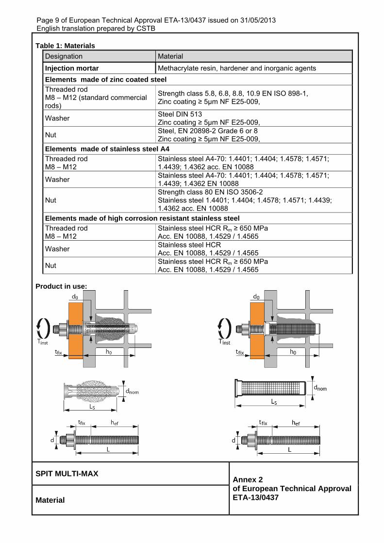
Table 1: Materials
Designation Material
Injection mortar Methacrylate resin, hardener and inorganic agents
Elements made of zinc coated steel Threaded rod M8 – M12 (standard commercial rods)
Strength class 5.8, 6.8, 8.8, 10.9 EN ISO 898-1, Zinc coating ≥ 5μm NF E25-009,
Washer Steel DIN 513 Zinc coating ≥ 5μm NF E25-009,
Nut Steel, EN 20898-2 Grade 6 or 8 Zinc coating ≥ 5μm NF E25-009,
Elements made of stainless steel A4 Threaded rod M8 – M12
Stainless steel A4-70: 1.4401; 1.4404; 1.4578; 1.4571; 1.4439; 1.4362 acc. EN 10088
Washer Stainless steel A4-70: 1.4401; 1.4404; 1.4578; 1.4571; 1.4439; 1.4362 EN 10088
Nut Strength class 80 EN ISO 3506-2 Stainless steel 1.4401; 1.4404; 1.4578; 1.4571; 1.4439; 1.4362 acc. EN 10088
Elements made of high corrosion resistant stainless steel Threaded rod M8 – M12
Stainless steel HCR Rm ≥ 650 MPa Acc. EN 10088, 1.4529 / 1.4565
Washer Stainless steel HCR Acc. EN 10088, 1.4529 / 1.4565
Nut Stainless steel HCR Rm ≥ 650 MPa Acc. EN 10088, 1.4529 / 1.4565
Product in use:
SPIT MULTI-MAX Annex 2 of European Technical Approval ETA-13/0437 Material
Page 10 of European Technical Approval ETA-13/0437 issued on 31/05/2013 English translation prepared by CSTB
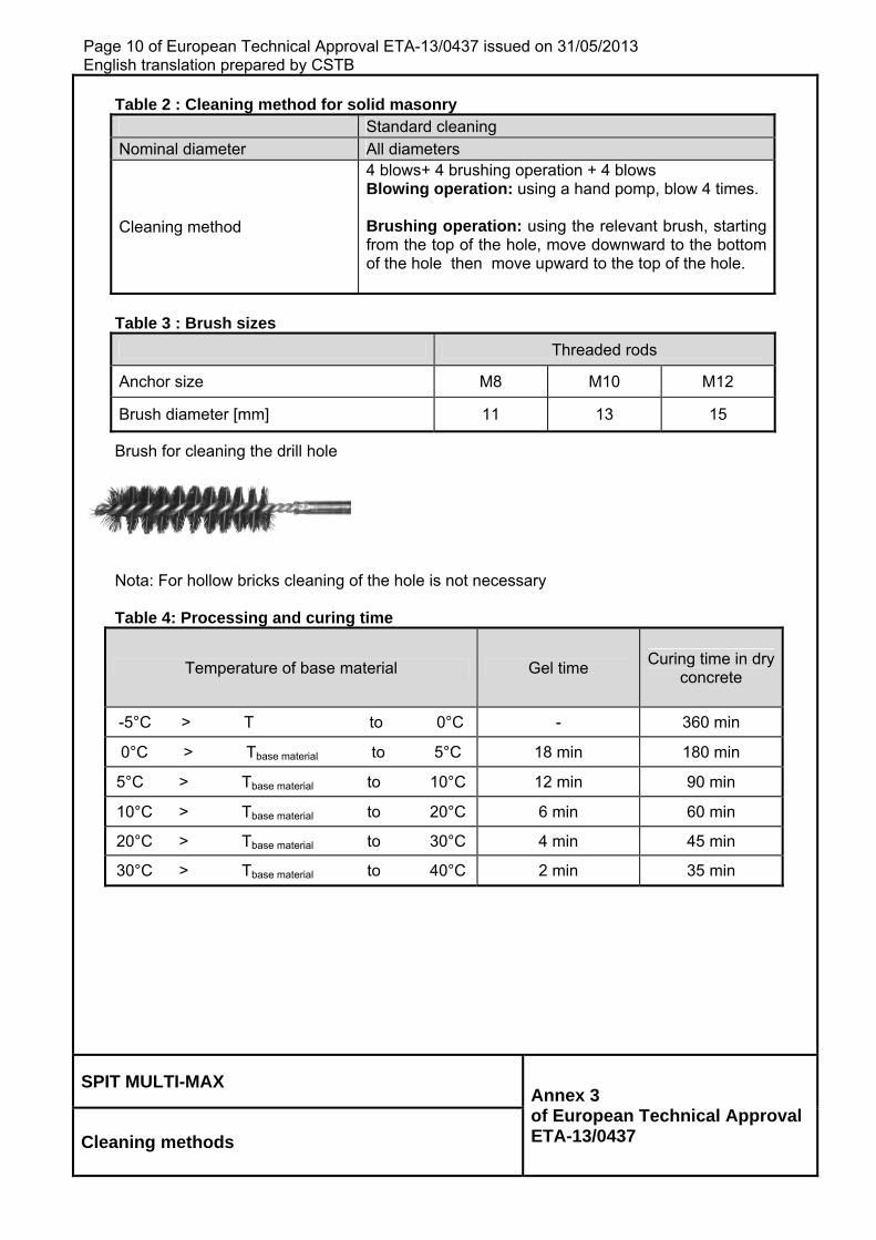
Table 2 : Cleaning method for solid masonry Standard cleaning Nominal diameter All diameters
Cleaning method
4 blows+ 4 brushing operation + 4 blows Blowing operation: using a hand pomp, blow 4 times. Brushing operation: using the relevant brush, starting from the top of the hole, move downward to the bottom of the hole then move upward to the top of the hole.
Table 3 : Brush sizes
Threaded rods
Anchor size M8 M10 M12
Brush diameter [mm] 11 13 15
Brush for cleaning the drill hole
Nota: For hollow bricks cleaning of the hole is not necessary
Table 4: Processing and curing time
Temperature of base material Gel time Curing time in dry
concrete
-5°C > T to 0°C - 360 min
0°C > Tbase material to 5°C 18 min 180 min
5°C > Tbase material to 10°C 12 min 90 min
10°C > Tbase material to 20°C 6 min 60 min
20°C > Tbase material to 30°C 4 min 45 min
30°C > Tbase material to 40°C 2 min 35 min
SPIT MULTI-MAX Annex 3 of European Technical Approval ETA-13/0437 Cleaning methods
Page 11 of European Technical Approval ETA-13/0437 issued on 31/05/2013 English translation prepared by CSTB
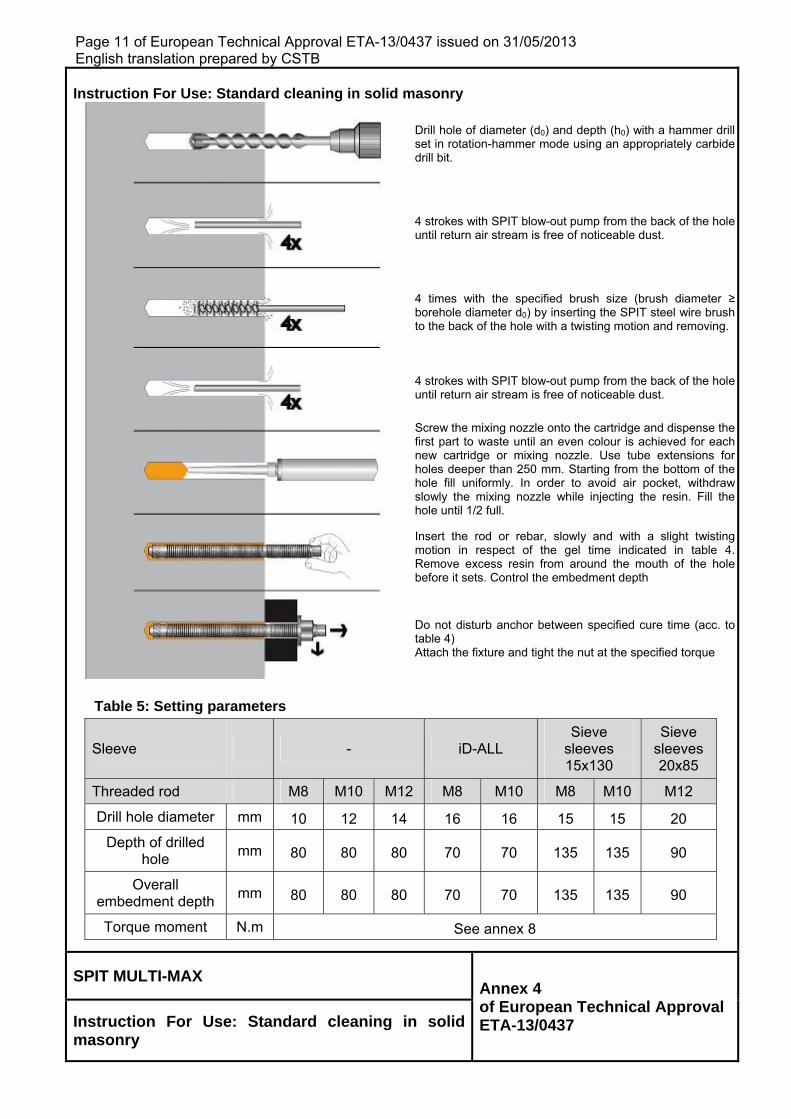
Instruction For Use: Standard cleaning in solid masonry
Drill hole of diameter (d0) and depth (h0) with a hammer drill set in rotation-hammer mode using an appropriately carbide drill bit.
4 strokes with SPIT blow-out pump from the back of the hole until return air stream is free of noticeable dust.
4 times with the specified brush size (brush diameter ≥ borehole diameter d0) by inserting the SPIT steel wire brush to the back of the hole with a twisting motion and removing.
4 strokes with SPIT blow-out pump from the back of the hole until return air stream is free of noticeable dust.
Screw the mixing nozzle onto the cartridge and dispense the first part to waste until an even colour is achieved for each new cartridge or mixing nozzle. Use tube extensions for holes deeper than 250 mm. Starting from the bottom of the hole fill uniformly. In order to avoid air pocket, withdraw slowly the mixing nozzle while injecting the resin. Fill the hole until 1/2 full.
Insert the rod or rebar, slowly and with a slight twisting motion in respect of the gel time indicated in table 4. Remove excess resin from around the mouth of the holebefore it sets. Control the embedment depth
Do not disturb anchor between specified cure time (acc. to table 4) Attach the fixture and tight the nut at the specified torque
Table 5: Setting parameters
Sleeve - iD-ALL Sieve
sleeves 15x130
Sieve sleeves 20x85
Threaded rod M8 M10 M12 M8 M10 M8 M10 M12
Drill hole diameter mm 10 12 14 16 16 15 15 20
Depth of drilled hole
mm 80 80 80 70 70 135 135 90
Overall embedment depth
mm 80 80 80 70 70 135 135 90
Torque moment N.m See annex 8
SPIT MULTI-MAX Annex 4 of European Technical Approval ETA-13/0437 Instruction For Use: Standard cleaning in solid
masonry
Page 12 of European Technical Approval ETA-13/0437 issued on 31/05/2013 English translation prepared by CSTB
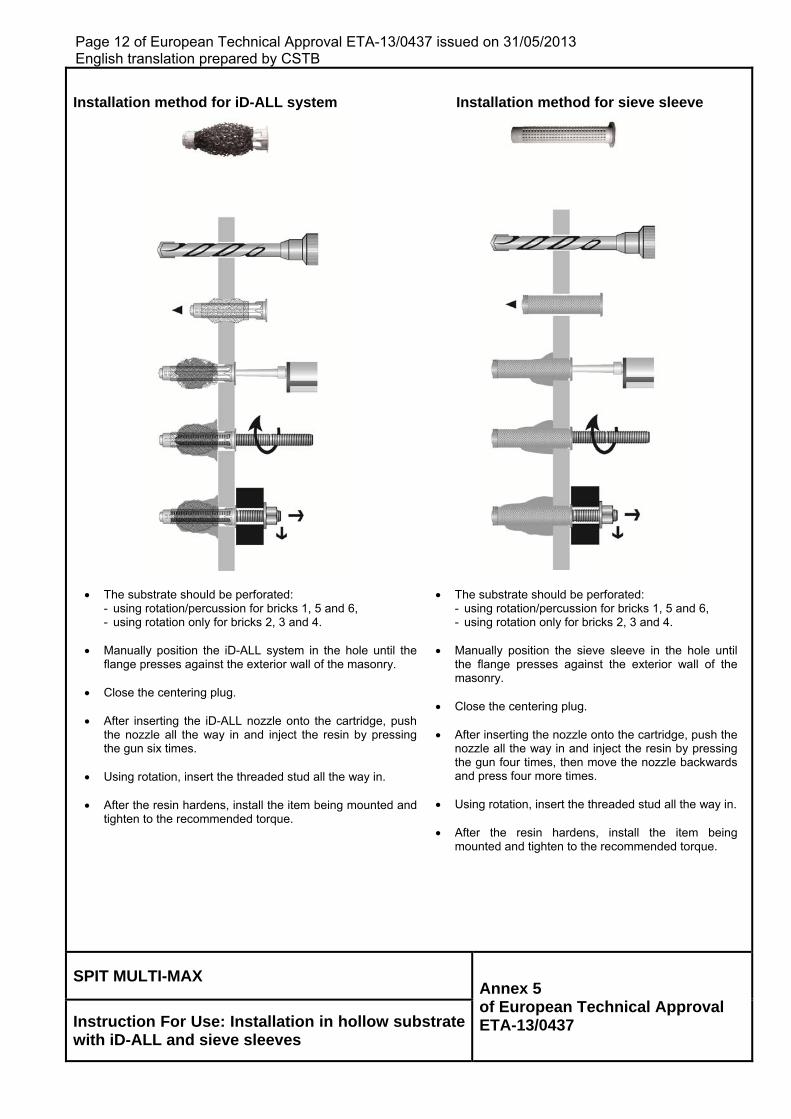
Installation method for iD-ALL system Installation method for sieve sleeve
The substrate should be perforated: - using rotation/percussion for bricks 1, 5 and 6, - using rotation only for bricks 2, 3 and 4.
Manually position the iD-ALL system in the hole until the
flange presses against the exterior wall of the masonry.
Close the centering plug. After inserting the iD-ALL nozzle onto the cartridge, push
the nozzle all the way in and inject the resin by pressing the gun six times.
Using rotation, insert the threaded stud all the way in.
After the resin hardens, install the item being mounted and
tighten to the recommended torque.
The substrate should be perforated: - using rotation/percussion for bricks 1, 5 and 6, - using rotation only for bricks 2, 3 and 4.
Manually position the sieve sleeve in the hole until
the flange presses against the exterior wall of the masonry.
Close the centering plug. After inserting the nozzle onto the cartridge, push the
nozzle all the way in and inject the resin by pressing the gun four times, then move the nozzle backwards and press four more times.
Using rotation, insert the threaded stud all the way in.
After the resin hardens, install the item being
mounted and tighten to the recommended torque.
SPIT MULTI-MAX Annex 5 of European Technical Approval ETA-13/0437 Instruction For Use: Installation in hollow substrate
with iD-ALL and sieve sleeves
Page 13 of European Technical Approval ETA-13/0437 issued on 31/05/2013 English translation prepared by CSTB
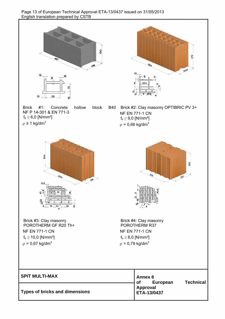
Brick #1: Concrete hollow block B40NF P 14-301 & EN 771-3 fb ≥ 6,0 [N/mm²]
≥ 1 kg/dm3
Brick #2: Clay masonry OPTIBRIC PV 3+
NF EN 771-1 CN fb ≥ 9,0 [N/mm²]
= 0,66 kg/dm3
Brick #3: Clay masonry POROTHERM GF R20 Th+
NF EN 771-1 CN
fb ≥ 10,0 [N/mm²]
= 0,67 kg/dm3
Brick #4: Clay masonry POROTHERM R37
NF EN 771-1 CN
fb ≥ 8,0 [N/mm²]
= 0,79 kg/dm3
SPIT MULTI-MAX Annex 6 of European Technical Approval ETA-13/0437 Types of bricks and dimensions
Page 14 of European Technical Approval ETA-13/0437 issued on 31/05/2013 English translation prepared by CSTB
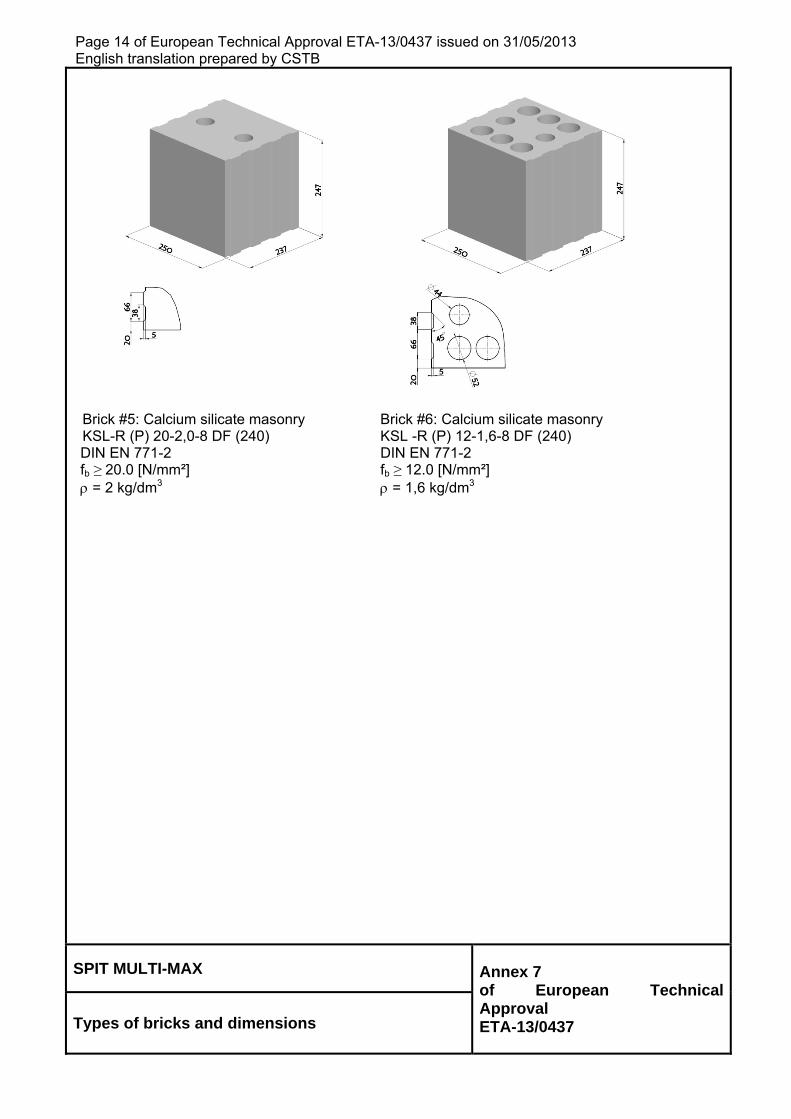
Brick #5: Calcium silicate masonry KSL-R (P) 20-2,0-8 DF (240) DIN EN 771-2 fb ≥ 20.0 [N/mm²] = 2 kg/dm3
Brick #6: Calcium silicate masonry KSL -R (P) 12-1,6-8 DF (240) DIN EN 771-2 fb ≥ 12.0 [N/mm²] = 1,6 kg/dm3
SPIT MULTI-MAX Annex 7 of European Technical Approval ETA-13/0437 Types of bricks and dimensions
Page 15 of European Technical Approval ETA-13/0437 issued on 31/05/2013 English translation prepared by CSTB
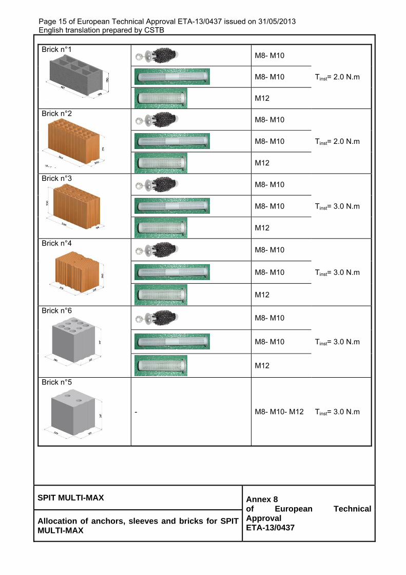
Brick n°1
M8- M10
Tinst= 2.0 N.m
M8- M10
M12
Brick n°2
M8- M10
Tinst= 2.0 N.m
M8- M10
M12
Brick n°3
M8- M10
Tinst= 3.0 N.m
M8- M10
M12
Brick n°4
M8- M10
Tinst= 3.0 N.m
M8- M10
M12
Brick n°6
M8- M10
Tinst= 3.0 N.m
M8- M10
M12
Brick n°5
- M8- M10- M12 Tinst= 3.0 N.m
SPIT MULTI-MAX Annex 8 of European Technical Approval ETA-13/0437
Allocation of anchors, sleeves and bricks for SPIT MULTI-MAX
Page 16 of European Technical Approval ETA-13/0437 issued on 31/05/2013 English translation prepared by CSTB
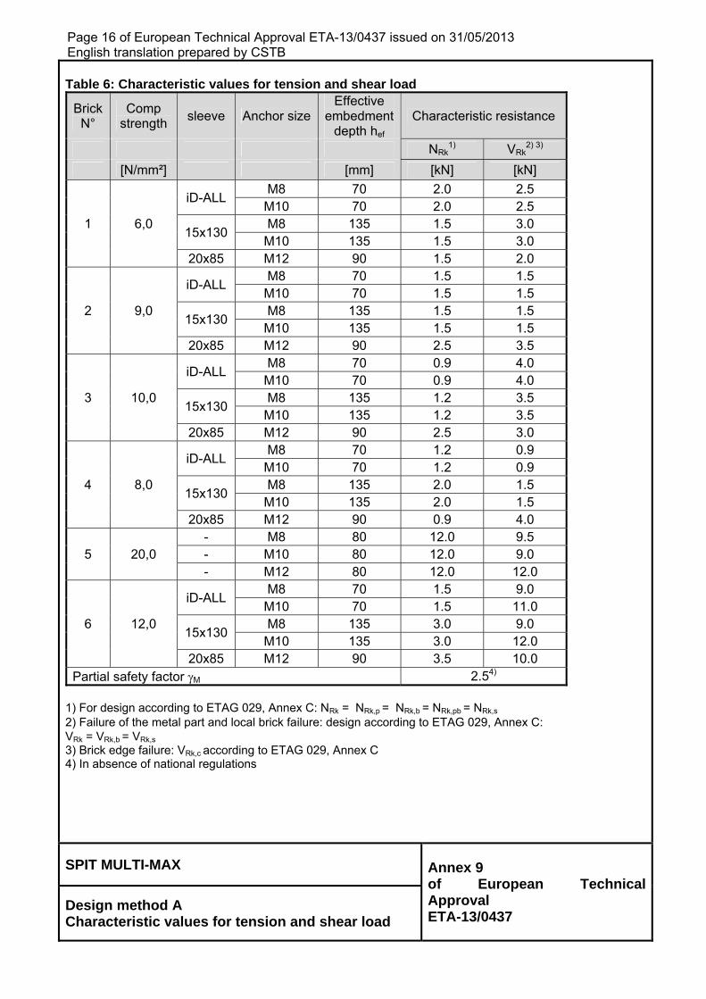
Table 6: Characteristic values for tension and shear load
Brick N°
Comp strength
sleeve Anchor sizeEffective
embedment depth hef
Characteristic resistance
NRk1) VRk
2) 3)
[N/mm²] [mm] [kN] [kN]
iD-ALL
M8 70 2.0 2.5 M10 70 2.0 2.5
1 6,0 15x130
M8 135 1.5 3.0 M10 135 1.5 3.0 20x85 M12 90 1.5 2.0
iD-ALL M8 70 1.5 1.5
M10 70 1.5 1.5 2 9,0
15x130 M8 135 1.5 1.5
M10 135 1.5 1.5 20x85 M12 90 2.5 3.5
iD-ALL M8 70 0.9 4.0
M10 70 0.9 4.0 3 10,0
15x130 M8 135 1.2 3.5
M10 135 1.2 3.5 20x85 M12 90 2.5 3.0
iD-ALL M8 70 1.2 0.9
M10 70 1.2 0.9 4 8,0
15x130 M8 135 2.0 1.5
M10 135 2.0 1.5 20x85 M12 90 0.9 4.0 - M8 80 12.0 9.5
5 20,0 - M10 80 12.0 9.0 - M12 80 12.0 12.0
iD-ALL M8 70 1.5 9.0
M10 70 1.5 11.0 6 12,0
15x130 M8 135 3.0 9.0
M10 135 3.0 12.0 20x85 M12 90 3.5 10.0
Partial safety factor M 2.54) 1) For design according to ETAG 029, Annex C: NRk = NRk,p = NRk,b = NRk,pb = NRk,s 2) Failure of the metal part and local brick failure: design according to ETAG 029, Annex C: VRk = VRk,b = VRk,s 3) Brick edge failure: VRk,c according to ETAG 029, Annex C 4) In absence of national regulations
SPIT MULTI-MAX Annex 9 of European Technical Approval ETA-13/0437
Design method A Characteristic values for tension and shear load
Page 17 of European Technical Approval ETA-13/0437 issued on 31/05/2013 English translation prepared by CSTB
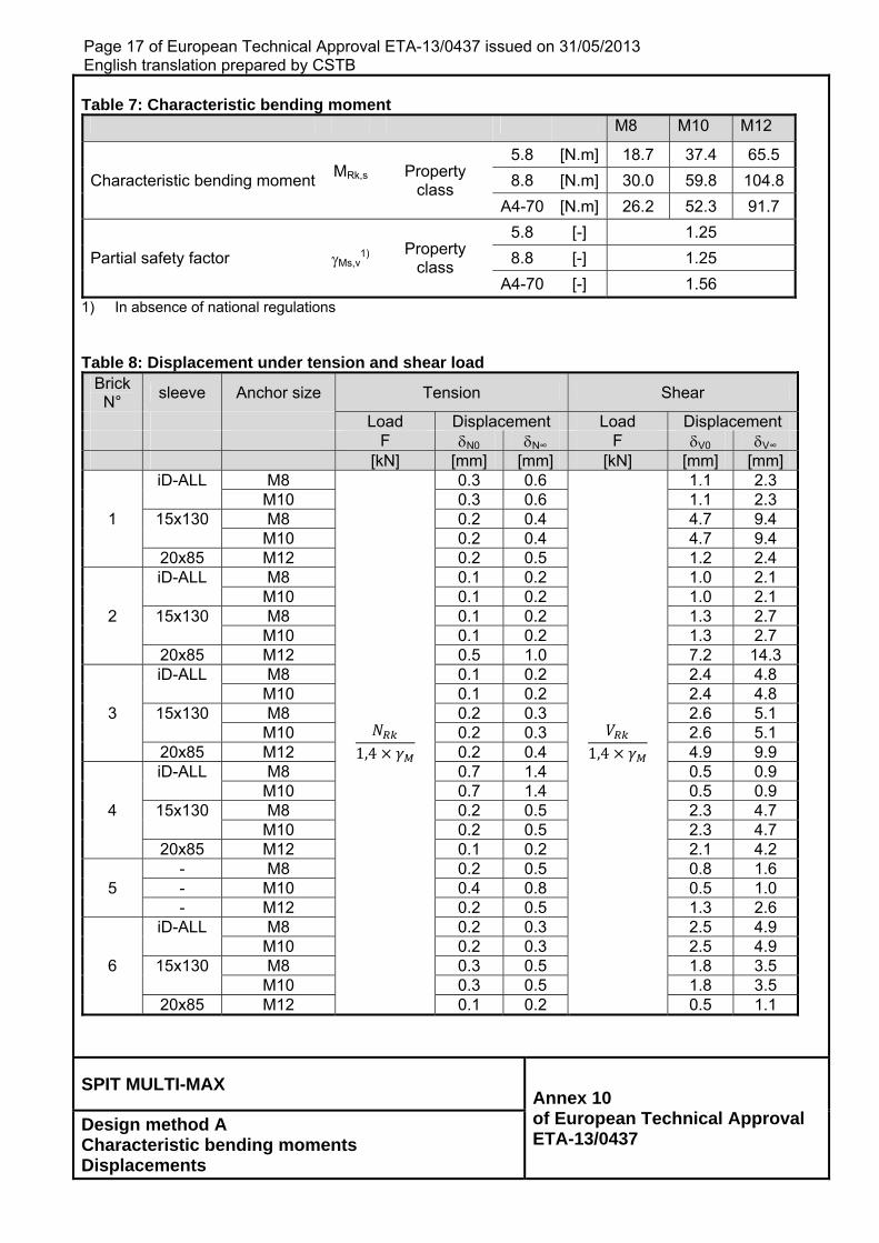
Table 7: Characteristic bending moment
M8 M10 M12
Characteristic bending moment MRk,s
Property class
5.8 [N.m] 18.7 37.4 65.5
8.8 [N.m] 30.0 59.8 104.8
A4-70 [N.m] 26.2 52.3 91.7
Partial safety factor Ms,v1) Property
class
5.8 [-] 1.25
8.8 [-] 1.25
A4-70 [-] 1.56
1) In absence of national regulations Table 8: Displacement under tension and shear load
Brick N°
sleeve Anchor size Tension Shear
Load Displacement Load Displacement F N0 N∞ F V0 V∞ [kN] [mm] [mm] [kN] [mm] [mm] iD-ALL M8
1,4
0.3 0.6
1,4
1.1 2.3 M10 0.3 0.6 1.1 2.3
1 15x130 M8 0.2 0.4 4.7 9.4 M10 0.2 0.4 4.7 9.4 20x85 M12 0.2 0.5 1.2 2.4 iD-ALL M8 0.1 0.2 1.0 2.1 M10 0.1 0.2 1.0 2.1
2 15x130 M8 0.1 0.2 1.3 2.7 M10 0.1 0.2 1.3 2.7 20x85 M12 0.5 1.0 7.2 14.3 iD-ALL M8 0.1 0.2 2.4 4.8 M10 0.1 0.2 2.4 4.8
3 15x130 M8 0.2 0.3 2.6 5.1 M10 0.2 0.3 2.6 5.1 20x85 M12 0.2 0.4 4.9 9.9 iD-ALL M8 0.7 1.4 0.5 0.9 M10 0.7 1.4 0.5 0.9
4 15x130 M8 0.2 0.5 2.3 4.7 M10 0.2 0.5 2.3 4.7 20x85 M12 0.1 0.2 2.1 4.2 - M8 0.2 0.5 0.8 1.6
5 - M10 0.4 0.8 0.5 1.0 - M12 0.2 0.5 1.3 2.6 iD-ALL M8 0.2 0.3 2.5 4.9 M10 0.2 0.3 2.5 4.9
6 15x130 M8 0.3 0.5 1.8 3.5 M10 0.3 0.5 1.8 3.5 20x85 M12 0.1 0.2 0.5 1.1
SPIT MULTI-MAX Annex 10 of European Technical Approval ETA-13/0437
Design method A Characteristic bending moments Displacements
Page 18 ofEnglish tra
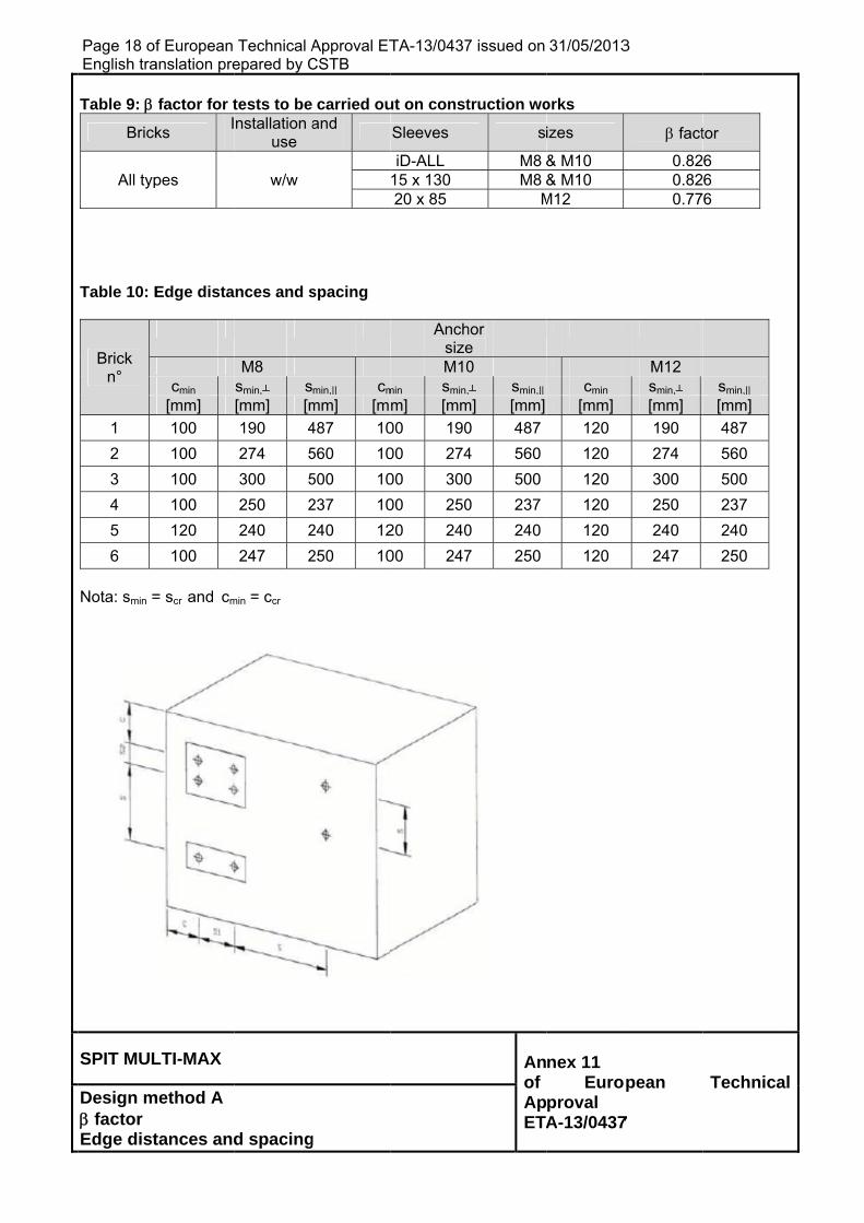
Table 9:
Brick
All typ
Table 10: E
Brick n°
1
2
3
4
5
6
Nota: smin =
SPIT MUL
Design m factor Edge dist
f European anslation pre
factor for t
ks I
pes
Edge dista
cmin
[mm]
100
100
100
100
120
100
= scr and cm
LTI-MAX
method A
tances and
Technical Aepared by C
tests to benstallation a
use
w/w
nces and s
M8 smin,┴ s[mm] [m
190 4
274 5
300 5
250 2
240 2
247 2
min = ccr
d spacing
Approval ETCSTB
carried ouand
spacing
min,|| cm
mm] [m
487 10
560 10
500 10
237 10
240 12
250 10
g
TA-13/0437
ut on const
Sleeves
iD-ALL 15 x 130 20 x 85
AnchsizeM10
min smin,
m] [mm
00 190
00 274
00 300
00 250
20 240
00 247
7 issued on
truction wo
s
M8 M8
M
hor e
0 ┴ smin,||
m] [mm]
0 487
4 560
0 500
0 237
0 240
7 250
Anof ApETA
31/05/2013
orks
izes
& M10 & M10
M12
cmin
[mm]
120
120
120
120
120
120
nex 11 Euro
proval A-13/0437
3
fact
0.820.820.77
M12 smin,┴ [mm]
190
274
300
250
240
247
pean
7
tor
6 6 6
smin,|| [mm]
487
560
500
237
240
250
Technicaal