Embed Size (px)
Citation preview
Gas Processing Journal
Vol. 8, No. 1, 2020, pp.37 - 48
http://gpj.ui.ac.ir
DOI: http://dx.doi.org/10.22108/gpj.2020.118993.1061
___________________________________________
* Corresponding Author. Authors’ Email Address: 1 M. Meratizaman ([email protected]), 2 H. Kazemi Afracoti ([email protected])
3 M. Shomali ([email protected]), ISSN (Online): 2345-4172, ISSN (Print): 2322-3251 © 2020 University of Isfahan. All rights reserved
Simulation and CFD Analyses of Condensing Shell and Tube Heat
Exchanger for CHP Package Application
Mousa Meratizaman 1*, Habibollah Kazemi Afracoti 2, Mohsen Shomali 3
1 Khaje Nasiriddin Tusi University of Technology [PhD], Tehran, Iran 2 Master of Science in Mechanical Engineering, Mazandaran University of Technology, Mazandaran,
Iran 3 Master of Science in Mechanical Engineering, Shahrood University of Technology, Shahrood, Iran
Received: 2019-09-02 Revised: 2020-01-24 Accepted: 2020-01-27
Abstract: Simulation and Computational Fluid Dynamic (CFD) analyses of condensing shell
and tube heat exchanger is subjected in this article. The condensing model using a User
Defined Function (UDF) through Ansys Fluent 18.2 is developed. Also, the heat transfer
between the shell and tube bundles is considered too. The subjected heat exchanger included
seven tubes with a length of 600 mm and a shell with a diameter of 90 mm. The effect of
different types of baffles and the distance between them is investigated in this article. All the
calculations were done in three different mass flow rates. Finally, the distribution of heat flow
is depicted for each stage of the considered heat exchanger. Results show that for the specific
geometry and constant distance between baffles, increment in the mass flow rate leads to
increasing the heat transfer coefficient. In addition, it shows that the formation of dew
droplets and condensed water is higher in the first geometry due to the maximum heat
transfer by hot flue gas.
keywords: Condensing Shell and Tube Heat Exchanger, UDF functions, Ansys Fluent 18.2,
Baffles, Heat transfer coefficient
Introduction
By reducing energy reserves and increasing
consumption in the industries, we will have to
optimize energy consumption. In this sector,
heat exchangers played an important role in
heat transfer in the process. The most common
and most widely used type of heat exchangers
used in the industry is shell & tube heat
exchangers designed and constructed for
various applications in various sizes.
With increasing energy costs worldwide,
manufacturers have always sought to improve
the quality of operation and use of proper
control equipment in the process. One of the
most important of which is to expand the use
of condensing shell and tube heat exchanger.
In this study, a condensing shell and a heat
exchanger are simulated using Ansys Fluent
software.
After selecting the appropriate mesh for
analysis (CFD), the calculation of the heat
transfer coefficient and the outlet temperature
in the fluid between the tube and shell
boundary are calculated numerically in
different baffle forms with the specified flow
rates. As mentioned, one of the ways to
improve efficiency is to use condensed heat
exchangers. The heat of hot gases from the
combustion of fuels contains steam with latent
heat. Recovering this heat can increase
efficiency by about 10 to 12%. When the smoke
reaches the lowest dew point, the steam
condenses and produces low pH acid with
sulfur or carbon dioxide present in the smoke.
Therefore, the choice of materials for corrosive
parts should be appropriate. Aluminum and
stainless steel are commonly used at high
temperatures. In the lower temperature parts
of heat exchanger components, plastics such as
UPVC are used which have an impact on the
final price. The generated condensate in a heat
exchanger has to be discharged into the sewer.
In this manner, heat exchangers are
manufactured in the lowest technical size. For
38 Gas Processing Journal, Vol. 8, No. 1, 2020
GPJ
removing the exhausted gas from narrow
channels, an induced fan is used in the
condensing heat exchangers.
Because the gases usually cooled below
100 °C, they do not have any other driving force
for the natural outflow of the chimney.
In the same research, Browne and Bansal
[1] carried out an overview of the condensation
heat transfer on a series of horizontal tubes
bundles. The application of transmission
models including the effects of steam in the
pipe bundle is still a difficult reason for
predicting the velocity distribution through the
tube bundles. The results show that: The rate
of cooling of the fluid has a significant effect on
the overall heat transfer coefficient for the
advanced levels of the pipes, but it has the
slightest effect on the smooth tubes. Osaka
et al [2], experimentally investigated
condensation heat transfers on horizontal
stainless-steel tubes by using actual flue gas
from a natural gas heat exchanger. This test is
based on various proportions of the flue gas
and a wide range of wall temperature. By
reducing the wall temperature, the wall
surface is covered with a thin layer of liquid.
The condensation heat transfer was well
predicted with a simple analogy correlation in
the high-wall-temperature region. In the low-
wall-temperature region, less than 30 °C, the
total heat transfer was higher than that
predicted by the analogy correlation. Sun et al
[3], experimentally studied a condensation
heat transfer of wet flue gases. The heat
transfer performance of the vapor-gas mixture
with vapor condensation was discussed. The
results showed that when water vapor
concentration is high in the wet flue gas
containing 𝑆𝑜2, plastic (e.g, PTFE) heat
exchangers can be used to recover sensible and
latent heat and to avoid acid corrosion.
The flue gas temperature drops and the
thermal efficiency is raised. In this method,
the temperature of the exhaust gases is
reduced and the thermal efficiency increases.
The condensation of water vapor in wet gases
dramatically increases the transmission of
heat. In experimental mode, the heat transfer
coefficient is twice as large as the transmission
of heat in a single-phase mode. Also, the
annular thin film condensation of water vapor
in wet flue gas flowing through a vertical tube
was studied theoretically and experimentally
by Peng et al [4].
Particularly the discussion of the effects of
condensation of low water vapor content (10 to
20 volume fractions) was carried out in the
heat transfer of vertical displacement loads.
The convection heat transfer was enhanced by
the condensation of the condensable gas
existing in the wet flue gas. This experiment
also showed that wall temperature is an
important factor affecting the condensation
rate and the fog formation in the wet flue gas.
Shee, et al [5].discussed the investigation of
the performance of compact heat exchanger for
latent heat recovery from exhaust flue gases.
Characteristics of the heat transfer and the
pressure of the heat exchanger, the inside of
the tube and the fin of a heat exchanger is
studied. Experimental results show that the
Colburn factor and friction coefficient for wet
air is larger than dry air. It has also been
determined that the coefficient f and j for moist
air increases by increasing the concentration of
steam.
In the next step, Lee et al [6] examined the
design factors for the heat exchanger and the
boiler using a simplified model from an
experimental heat exchanger. Characteristics
of Specifications of each heat exchanger
component (e.g., an upper heat exchanger
(UHE) and lower heat exchanger (LHE); coil
heat exchanger (CHE); baffles) were
investigated using a model apparatus, and the
comprehensive performance of the pilot gas
boiler was examined experimentally.
When the optimal heat exchangers were
designed, the heat output of the boiler was
about 90%. Compared to a typical Bunsen-type
boiler, the heating efficiency is improved by
about 10%. Goel [7], of the University of
Pennsylvania, USA, reports the possibility of
recovering heat and water from gas by using a
condensing heat exchanger. The effects on
water efficiency, general health, and annual
costs were investigated and analyzed for five
different methods.
The effect of different design parameters
such as pipe length and width of the converter
pipe and their diameter were investigated. Five
different thermal arrangements were evaluated
to identify the design of a heat exchanger,
which would increase the high condensation
and the heat transfer velocity. Both the fluid
flow of the flue gas and the cooling water
stream, when it passes through the heat
exchanger, eliminates the pressure and,
therefore, the cooling water produces a higher
pressure, resulting in high operating costs.
Changing tube diameter has significant
effects on the total heat transfer coefficient and
condensation efficiency. Wang et al [8], On the
basis of the analysis of the mechanism of
increasing the heat transfer in the inner tubes,
suggested a new type of symmetric tubes with
left and right fins. The type of tubes has the
potential to increase the heat transfer.
Experimental results show that excess air
coefficient, the cooling water flow rate, the
Simulation and CFD Analyses of Condensing Shell and Tube Heat Exchanger for CHP Package Application 39
GPJ
water inlet temperature, and the𝑅𝑒 number
have prominent effects on the convection-
condensation heat transfer. The left right
symmetric internally finned tube can
effectively decrease the radial temperature
gradient reduce the thickness of the non-
condensable gas layer and significantly
strengthen the water vapor condensation.
Lane et al [9], also, a numerical study has been
carried out to investigate the heat and mass
transfer characteristics of a condensing
combustion flue gas in a cross-flow transport
membrane tube bundle.
The tube wall is made of a porous material
that is able to extract condensate liquid from
the flue gas. The flue gas investigated consists
of one condensable water vapor (𝐻2𝑜).) and
three non-condensable gases (𝑁2 . 𝐶𝑜2 . 𝑂2). A
simplified multi-species simple transport
model is designed to transfer the mass and
heat of combustion fuels. The condensation-
evaporation process was simulated as a two-
step chemical reaction. The numerical study
was conducted within ranges of Reynolds
number of 1 ∙ 0 × 103 − 7 × 10⁴ based on
hydraulic diameter of flue gas channel, and
6 ∙ 4 × 100 − 3 ∙ 3 × 10² based on the inner
diameter of the water tube.
As the Reynolds number of the flue gas
increases, the evaporation rate of the heat and
mass decreases. Precise results on
temperature, mass fraction, enthalpy and shell
fraction coefficients are also presented. As a
result, the overall performance of the pipes in
the heat recovery from water is high when the
chimney gas is lower in Reynolds numbers. In
another step, Soheil Soleimani et al [10], from
the University of Florida studied numerically
the effects of different condensation heat
exchanger performance.
The effects of inhospitable gases on
condensation or condensation rates along with
the number of pipe spacing (TMCs) in the
direction of transverse and longitudinal tubes
were investigated. Numerical simulation is
performed using Ansys Fluent commercial
software and condensation and mass transfer
are defined using specific functions.
The results show that the increase in the
number of TMC tubes, when the input flow
rate is constant, increases both condensation
levels and the average temperature has
opposite effects on the density, both of which
should be considered in industrial applications.
In this study, the effects of the longitudinal
and transverse steps of TMC pipe bundles
based on heat exchangers were studied
numerically.
Investigations showed that the heat
transfer rate increases with increasing the
amount of intake steam vapor, in addition to
increasing the longitudinal and transverse
steps of the reverse effect on the amount of
heat transfer from the flue gas to the cooling
water inside the TMC. In addition, the results
showed that the heat transfer rate increased
with increasing the amount of mass fraction of
the vapor of the incoming water.
In addition, increasing the longitudinal and
transverse steps has a negative effect on the
amount of heat transfer from the flue gas to
the cool water inside the pipes. Emerging and
low-temperature water recycling using a
ceramic membrane in a heat exchanger is a
thriving technology that can be used to
increase the efficiency of boilers and gas or coal
boilers in various industrial processes and
conventional plants.
The wall of a tube is a TMC-based heat
exchanger capable of extracting pure water
from the flue gas in the presence of other
incompressible gases by means of a Nano-
prussic state. Soheil Soleimani et al [11], In
this paper, a numerical study was conducted to
study the effects of longitudinal and transverse
steps of TMC pipes on the performance of
cross- flow heat exchangers. A multi-functional
heat transfer model has been used to study the
properties of heat transfer and the mass of a
chimney gas in two symmetric pipes. Different
steps (0.4-0.6) inches and longitudinal steps
(0.4-0.8) have been used.
Numerical results show that the effect of
transition steps on the output parameters is
more evident. The results also show that
longitudinal and transverse steps are one of
the key parameters in the recovery of water
and heat in a TMC pipe bundle and can be
used to obtain an optimal state for maximizing
the performance of cross- flow heat
exchangers.
Terhan and Kumakley [12], studied on a
heating system using 60 MW of natural gas to
recover heat from the flue gas. They used One-
dimensional mode (FDM) to calculate the
chimney gas. The design was carried out on a
gas condenser with an outer diameter of 34
mm and a thickness of 12 mm in the form of
u-shaped tubes. Based on the calculated
results, the chimney gas temperature can be
reduced to 40 ° C by a gas- fired condenser of
80 square meters.
After the combustion of natural gas, the
output chimney gas contains a lot of water
vapor. The hidden water vapor heat in the flue
gas is 10 to 11% lower than the natural gas
heat content, respectively. That is, if the
condensed heat from the flue gas (gas) is
40 Gas Processing Journal, Vol. 8, No. 1, 2020
GPJ
improved, energy efficiency can increase
significantly. To investigate the compression
flow patterns and the mechanisms for heat
transfer and mass in different flow regimes, a
horizontal shell- side condenser has recently
been tested for a multifunctional condensation
by Gu and et al [13].
The horizontal condenser is made up of 36
pipes with alternative modes and tubes. Steam
and air mixture was also used as a test fluid.
This paper provides empirical results on shell-
shaped condensation patterns with transfer
properties. The results are as follows:
Condensation flow patterns and convective
properties of a series of horizontal pipe bundles
are significantly different from the horizontal
condensation tubes. On the other hand,
parameter F is presented to determine the flow
patterns of condensation flow based on
laboratory data and studies.
This function expresses the shear forces,
the gravitational forces, and the tensile force of
the fluid. By increasing the flow of non-
condensing gases, the coefficient of
condensation heat transfer of flow patterns
decreases, because a high concentration of
incompressible gases can reduce the portion of
the condensation pressure of the steam and
reduce the temperature of the liquid-vapor.
Most industrial systems include heat
transfer facilities with non-design conditions
during periods of their working cycle. Study
and performance for off-design situations is an
important part of any industrial system that
ensures the safety and performance of the
system for a wide range of operating
conditions. In this context, Lane et ai [14]
examined the numerical simulation of a heat
exchanger shell and a TMC pipe for off-design
operating conditions.
Modeling multi-component multiphase
model and UDF functions and commercial flue,
the density model, heat and mass transfer are
modeled in a heat exchanger. In this study, the
effects of various parameters such as incoming
cooling temperature, flue gas mass flow rate
and cool water on the overall heat transfer and
condensation rate in the TMC tube heat
exchanger have been numerically investigated.
Changes in boundary conditions have been
shown to indicate that heat transfer and
condensation rates increase with increasing
flue gas flow rate. The results also showed that
increasing the temperature of cold water
reduces the overall heat transfer and
condensation rate.
another study, pipes with a ceramic body
shell as a condenser are investigated to recover
the heat transfer from smoke from the
chimney to heat the water by Wang et al [15].
The effects of operating parameters such as
fluid flow rate (water-gas), flue gas
temperature and cool water, as well as flue gas
humidity, are in process performance for the
mass and heat transfer along the studied shell.
In particular, the overall transmission
coefficient is also calculated.
Increasing the flow rate of water or
reducing the cooling temperature can
effectively improve the efficiency and transfer
of heat and mass. Increasing the inlet gas
temperature can increase and improve the flow
of water and heat, but does not increase the
transmission efficiency. The increase in the
humidity of the flue gas can significantly
increase the amount of water and heat transfer
and the total coefficient of transfer, but it has a
small effect on water and heat.
Fin wall models (wall fins) with different
shapes have many effects on the gas flow have
a chimney that affects the performance of the
plasma converter. In this paper, a numerical
model of heat exchangers based on CFD theory
and characteristics of heat and flow
transmission from chimney gas was studied
using CFD and experimental methods.
Cao [16] proposed the optimal shape of the
Finn wall for the chimney gas duct. The results
show that traditional circular fines reduce the
effects of contact time and the effects of the
transfer of heat between the chimney and the
Fin. When used with elliptical fins, the
retardation location and the effects of heat
transfer zones are up to 7.6% and the mean
transmittance of the radiation is increased by
12.1%. In the end, an appropriate formula for
the transfer coefficient of convection and
Nusselt number is obtained in optimal
conditions.
Yin et al [17] obtained a three-dimensional
numerical simulation of the VOF method,
carried out from the condensate flow of water
vapor, with the presence and presence of
uncompromising interference of gases inside a
1 mm mini-tube. A UDF function (defined
functions) has been applied to phase changes
in a circular flow pattern. The temperature of
the interface is assumed to be the saturation
temperature of the water vapor. The effect of
input speed, wall temperature, saturation
temperature and super-heater temperature for
pure water vapor concentration has been
investigated.
The air is initially selected as an
uncompromising gas, and then the volume of
input is changing from 0.5-0.3 percent. In
addition, the effect of incompressible gases on
the condensation has been investigated. The
results of this study can be extracted from the
following way: The pure steam transfer
Simulation and CFD Analyses of Condensing Shell and Tube Heat Exchanger for CHP Package Application 41
GPJ
coefficient is almost independent of the input
velocity and super heater temperature, but
with high saturation, temperatures increase
the temperature difference between the
saturation and the high wall temperatures.
The steam quality is linearly reduced from
input to output. When the condensation is
mixed with an uncompromising gas, the mass
transfer rate along the joint is severely
reduced, resulting in higher vapor quality at
the outlet and a significant drop in the heat
transfer coefficient.
Chen et al. [18] conducted an experimental
study on porous ceramic membranes for the
removal of water and heat from flue gases
under different conditions. Experimental
results showed that the recovered water and
heat flux increase as the feed gas flux rises,
but a higher water recovery rate is achieved in
a lower feed gas flow rate and the heat
efficiency decreases for the saturated feed gas.
When the feed gas flow rate grows, the
promoting effect of the growth of temperature
on the water recovery is more obvious. And the
heat recovery efficiency increases with the
growth of gas temperature within the feed gas
temperature range (50–70 °C). The higher the
relative humidity, the greater the amount of
recovered water and heat are at the same
temperature. Water recovery rate increases
and reaches the peak at the condition of
RH = 100% as the relative humidity rises, but
the heat recovery efficiency is otherwise. The
change of cooling water flux has little influence
on the performance of the membrane but its
rise can promote heat recovery. The amount of
recovered water and heat, the water recovery
rate and heat recovery efficiency decreases
with the increase of inlet temperature of
cooling water. However, due to the capillary
condensation, the membrane can still maintain
the amount of recovered water of about 0.5
kg/(m2.h) and the water recovery rate of about
20–30%, when the temperature of cooling
water increases to 65 °C (the water dew point
is 60 °C).
In this research, 27 different configurations
for the heat exchanger are compared to
determine the optimum configuration. These
configurations are various in terms of baffle
shapes, the number of baffles and the flux flow
rate.
Material and Methods
In this paper, a shell and tube heat exchanger
condensing are used to check the heat transfer
coefficient and temperature at the boundary
between pipe and shell fluid, which are
specified in different shapes of baffles with
different mass. Some of the geometric
parameters presented in Table 1 are water and
flue gases as working fluid inside the tube and
the shell side. Here, the effects of different
baffles on different fluxes on the heat transfer
coefficient and the water outlet temperature of
the converter are investigated, and by reducing
the distance between the baffles, we examine
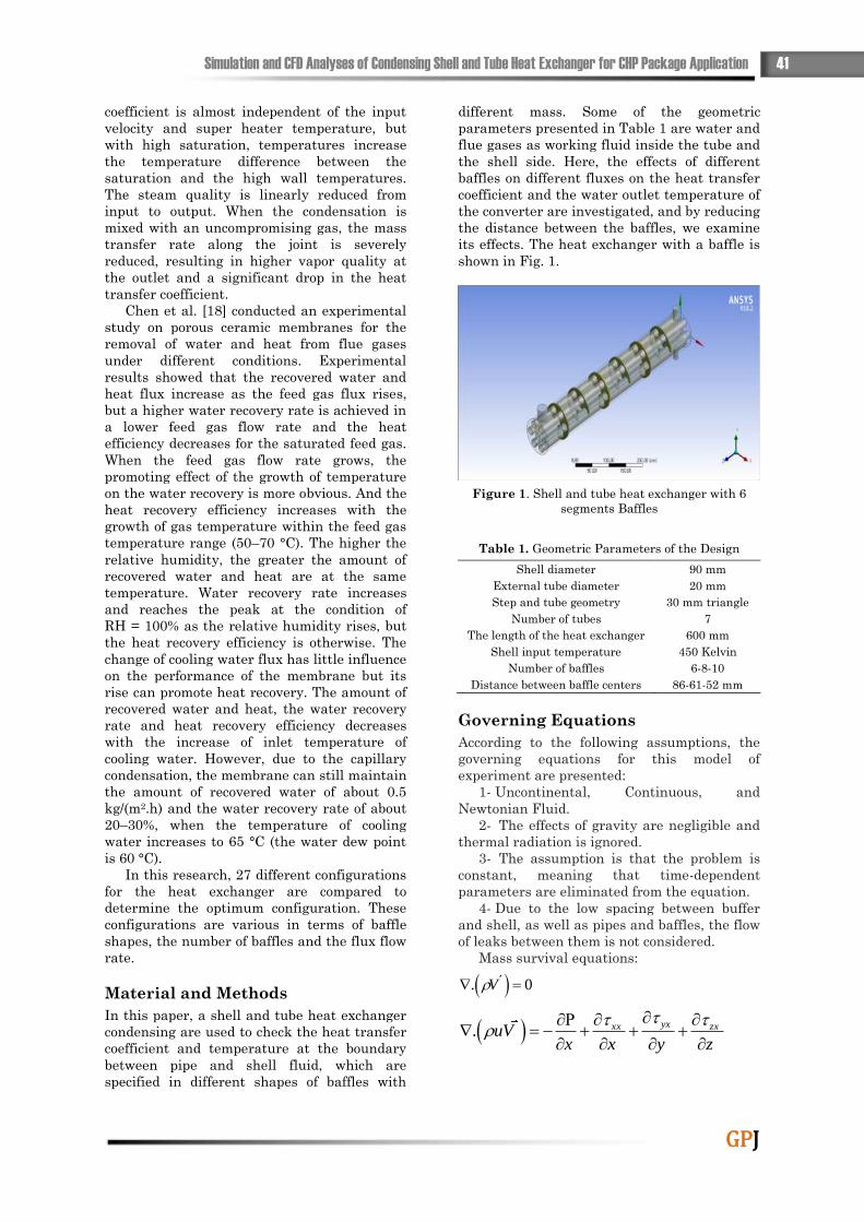
its effects. The heat exchanger with a baffle is
shown in Fig. 1.
Figure 1. Shell and tube heat exchanger with 6
segments Baffles
Table 1. Geometric Parameters of the Design
Shell diameter 90 mm
External tube diameter 20 mm
Step and tube geometry 30 mm triangle
Number of tubes 7
The length of the heat exchanger 600 mm
Shell input temperature 450 Kelvin
Number of baffles 6-8-10
Distance between baffle centers 86-61-52 mm
Governing Equations
According to the following assumptions, the
governing equations for this model of
experiment are presented:
1- Uncontinental, Continuous, and
Newtonian Fluid.
2- The effects of gravity are negligible and
thermal radiation is ignored.
3- The assumption is that the problem is
constant, meaning that time-dependent
parameters are eliminated from the equation.
4- Due to the low spacing between buffer
and shell, as well as pipes and baffles, the flow
of leaks between them is not considered.
Mass survival equations:
. 0V
.yxxx zxuV
x x y z
42 Gas Processing Journal, Vol. 8, No. 1, 2020
GPJ
.xy yy zy
vV gy x y z
.yzxz zzwV
z x y z
. . .eV V k T q
2 22 2
2u v w u v
x y z y x
22
2
.u w v w
Vz x z y
The two-order accurate volume of fluid
(VOF) method which is a free-surface modeling
technique is used in this work [17]:
φ = ∑ 𝛼𝑞𝜑𝑞
𝑛
1
𝑤𝑖𝑡ℎ 𝜑 = 𝜌. 𝑘. 𝜇
φ =1
𝜌∑ 𝛼𝑞𝜌𝑞𝜑𝑞
𝑛
1
𝑤𝑖𝑡ℎ 𝜑 = 𝑐𝑝
∇ ∙ (𝛼𝑞𝜌𝑞𝑣→
𝑞) = �̇�
∇ ∙ (𝜌𝑣→
𝑣→) = −∇𝑝̅̅̅̅ + ∇̅ ∙ [𝜇(∇̅𝑣 + ∇̅𝑣𝑇)] + 𝜌�⃗� + �⃑�
∇̅ ∙ (𝑣(𝜌𝑐𝑝𝑇 + 𝑝)) = ∇̅ ∙ (𝑘∇̅𝑇) + 𝐿𝐻�̇�
𝐹 = ∑ 𝜎𝑖𝑗
𝛼𝑖𝜌𝑖𝑘𝑗∇̅𝛼𝑗 + 𝛼𝑗𝜌𝑗𝑘𝑖∇̅𝛼𝑖
(𝜌𝑖 + 𝜌𝑗)𝑖𝑗.𝑖<𝑗
𝜌𝐷𝑉
𝐷𝑡= 𝜌𝑓 − 𝛻𝑃 + 𝜇𝛻2𝑉
To simulate mean flow characteristics for
turbulent flow conditions k − εmodel is applied
which consist of transport equations [9]:
𝐾 =1
2𝑢𝑖
′𝑢𝑖′̅̅ ̅̅ ̅̅ 휀 = (
𝜇
𝜌) 𝑢𝑖.𝑗
′ 𝑢𝑖.𝑗′̅̅ ̅̅ ̅̅ ̅̅
𝜇𝑡 ∝ 𝜌𝑢𝑙𝛿𝑙
𝑢𝑙 ∝ √𝑘
𝛿𝑙 ∝√𝑘3
휀
𝜌𝜕𝑘
𝜕𝑡+ 𝜌𝑢𝑗𝑘.𝑗 = (𝜇 +
𝜇𝑡
𝜎𝑘𝑘.𝑗)
.𝑗
+ 𝐺 + 𝐵 − 𝜌휀𝜌𝜕휀
𝜕𝑡
+ 𝜌𝑢𝑗휀.𝑗
= (𝜇 +𝜇𝑖
𝜎𝜀휀.𝑗)
.𝑗
+ 𝐶1
휀
𝑘𝐺
+ 𝐶1(1 − 𝐶3)휀
𝑘𝐵 − 𝐶2𝜌
휀2
𝑘
Boundary Conditions
To simplify numerical simulation, some of the
essential features of the process are assumed
to be.
1. The thermal properties of the shell side
are constant.
2. The flow of fluid and heat transfer in a
turbulent process and is stable.
3. The leakage between the pipe and the
baffle, as well as between the baffle and the
shell, is not considered.
The value of the flow rate and the desired
temperature at the input of the heat exchanger
is determined. The input temperature to the
shell is 450 K and the nozzle size is set to zero.
The specification of the input speed is assumed
to be uniform and the non-slip condition is
considered for all levels.
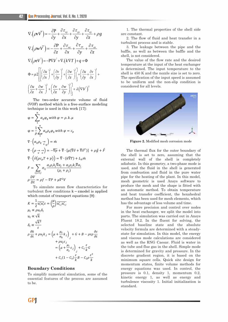
Figure 2. Modified mesh corrosion mode
The thermal flux for the outer boundary of
the shell is set to zero, assuming that the
external wall of the shell is completely
adiabatic. In this geometry, a two-phase mode is
used, and the fluid in the shell is generated
from combustion and fluid in the pure water
pipe for the heating of the plant. In this model,
mesh geometric is used Ansys software to
produce the mesh and the shape is fitted with
an automatic method. To obtain temperature
and heat transfer coefficient, the hexahedral
method has been used for mesh elements, which
has the advantage of less volume and time.
For more precision and control over nodes
in the heat exchanger, we split the model into
parts. The simulation was carried out in Ansys
Fluent 18.2. In the fluent for solving, the
selected baseline state and the absolute
velocity formula are determined with a steady-
state for simulation. In this model, the energy
and viscous mode calculations are considered
as well as the RNG Caesar. Fluid is water in
the tube and flue gas in the shell. Simple mode
is determined for gravity and pressure. In the
discrete gradient region, it is based on the
minimum square cells. Quick site design for
momentum states, finite volume methods for
energy equations was used. In control, the
pressure is 0.1, density 1, momentum 0.2,
kinetic energy 1, as well as energy and
turbulence viscosity 1. Initial initialization is
standard.

Simulation and CFD Analyses of Condensing Shell and Tube Heat Exchanger for CHP Package Application 43
GPJ
Results and Discussion
To confirm the CFD modeling in the referenced
article [18], the correctness of a complete
model for fluid flow in a condenser heat
exchanger is shown by the results with the
data in the research.
Verification
As a first step in the present study, a three-
dimensional numerical simulation of the
constant was performed by finite volume
method for condensing water vapor in a mini-
horizontal tube, despite incompressible gases. A
function defined for phase changes is used. For
the input boundary conditions, the speed
distribution for single-phase simulation is used.
Figure 3. The miniature tube related to the
projection geometry
Under operating conditions one
atmosphere, the saturation temperature of
steam is 373 K, when the wall is isothermal at
uniform temperature. The speed and pressure
algorithms have been used in simple mode
while presto (Pressure-Taggering-Option) has
been used in the simulation of pressure
interpolation.
In order to obtain a liquid-liquid interface,
the mesh size near the wall in which the
condensate liquid film is produced is much
smaller than the vapor area. Meanwhile, mesh
size is relatively axial in comparison with the
radial direction. Seven mesh sets representing
a number of cells are examined. The results
show that the grid mesh is more important in
a radial direction.
As a result, the network type is selected
from the Hexahedral mode.
Figure 4. Output pipe mesh in Ansys 18.2
Here, the effects of the difference of
saturation vapor temperature and wall
temperature were studied in heat transfer
performance. The saturation temperature
ranges from 373 K to 343 K, while the input
speed remains at 10 m / s. The difference
between the wall temperature and the
saturated vapor is about 5 to 20 Kelvin.
Table 2. The percentage difference between the
reference and the results CFD
𝑻𝒔
− 𝑻𝒘
K
Heat transfer coefficient 𝒘 ∙ 𝒎−𝟐 ∙ 𝒌−𝟏
Difference
percentage
Error(%) Reference
results
CFD
results
5 3.00E+03 2936.188 -2.28569
10 2.78E+03 2793.3 0.447916
15 2.67E+03 2652.465 -0.61325
20 2.62E+03 2589.684 -0.97795
Table 2 shows the percentage difference
between the reference and the CFD results.
From Fig. 5, it can be concluded that the
saturation temperature has an extraordinary
effect on the heat transfer coefficient of
condensation.

44 Gas Processing Journal, Vol. 8, No. 1, 2020
GPJ
Figure 5. Condensation heat transfer coefficient
graph based on the difference in saturation and wall
temperature
In comparison with the saturation
temperature of 373 K, the reduction of the
coefficient of the average heat transfer from
28.9%, 58.7%, and 84.1%, respectively, is due
to saturation temperatures of 343, 353 and 363
K. It may be due to molecular activity and
weakening the relationship between the vapor
and liquid phase at low temperature and low
pressure. In addition, the amount of heat
transfer coefficient decreases as the saturation
temperature decreases. As shown in Fig. 5, the
reference miniature tube and the CFD results
were checked for different saturation and wall
temperatures, and the output temperature and
pressure were verified by the research [18].
This chart shows that it is in good alignment
with the reference. We checked this mode for
three different masses.
Results
In this study, a shell and tube heat exchanger
condenser model has been modeled in
sufficient detail to solve the flow and
temperature field. In this solution, the two-
phase method is used and the heat exchanger
has a flow, the fluid is inside the pure water
pipe, and there is between the outer wall of the
tube and the flame generated from the
combustion shell. The inlet temperature of the
smoke gas is 450 Kelvin and the input water
temperature is 310.9 Kelvin. In Figure 6, the
various baffles used in this study are shown.
First geometry of Baffle
Second geometry of Baffle
Third Baffle Geometry
Figure 6. Different forms of baffles used in research
geometry
Table 3 shows the characteristics of the
fluid and the input flow. The results of
simulation of CFD, heat transfer and pressure
drop in a condenser heat exchanger have been
obtained. The results are obtained by changing
the spacing of the baffles between 6, 8, 10 in
three different baffles for the flux flow rate of
0.024-0.034-0.044 kg / s.
Table 3. Specifications of water and gas from
combustion
450 Kelvin Input temperature Combustion
gas 0.024-0.034-0.044 Flow rate
𝐶𝑜2 − 𝑁2 − 𝑂2 − 𝐻2𝑂 Gas combinations
310.9 K Input temperature Water fluid
0.325 Flow rate
Adiabatic The outer wall of the shell
Aluminum The inner tube genus
Simulation and CFD Analyses of Condensing Shell and Tube Heat Exchanger for CHP Package Application 45
GPJ
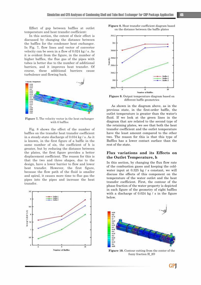
Effect of gap between baffles at outlet
temperature and heat transfer coefficient:
In this section, the extent of their effect is
discussed by changing the distance between
the baffles for the condenser heat exchanger.
In Fig. 7, flow lines and vector of converter
velocity can be seen in a flow of 0.024 kg / s. As
it is evident from the figure, in the number of
higher baffles, the flue gas of the pipes with
tubes is better due to the number of additional
barriers, and it improves heat transfer. Of
course, these additional barriers cause
turbulence and flowing back.
Figure 7. The velocity vector in the heat exchanger
with 6 baffles
Fig. 8 shows the effect of the number of
baffles on the transfer heat transfer coefficient
in a steady-state discharge of 0.034 kg / s. As it
is known, in the first figure of a baffle in the
same number of six, the coefficient of h is
greater, but by reducing the distance between
the plates, the first figure provides a better
displacement coefficient. The reason for this is
that the two and three shapes, due to the
design, have a lower barrier to flow and lower
heat transfer. However, the first figure,
because the flow path of the fluid is smaller
and spiral, it causes more time to flue gas the
pipes into the pipes and increase the heat
transfer.
Figure 8. Heat transfer coefficient diagram based
on the distance between the baffle plates
Figure 9. Output temperature diagram based on
different baffle geometries
As shown in the diagram above, as in the
previous state, in the first-order baffle, the
outlet temperature is greater than the water's
fluid. If we look at the green lines in the
diagram that are related to the second type of
the retaining plates, we see that both the heat
transfer coefficient and the outlet temperature
have the least amount compared to the other
two. The reason for this is that this type of
Baffles has a lower contact surface than the
rest of the state.
Flux variations and its Effects on
the Outlet Temperature, h
In this section, by changing the flux flow rate
of the combustion gases and keeping the cold-
water input at 0.325 kg / s constant, we will
discuss the effects of this component on the
temperature of the water outlet and the heat
transfer coefficient. First, the contour of the
phase fraction of the water property is depicted
in each figure of the geometry of eight baffles
with a discharge of 0.024 kg / s in the figure
below.
Figure 10. Contour cutting from the center of the
fuzzy fraction H_2O
46 Gas Processing Journal, Vol. 8, No. 1, 2020
GPJ
As shown in Fig. 10, the formation of dew
droplets, or the water produced from the
condensate, is higher in the first figure due to
the higher heat transfer and the higher heat
that loses the flue gas and, respectively, in the
third and second geometries, due to lower heat
transfer with droplets dew is less. Here we can
conclude that the first Baffle geometry can
have a higher heat transfer than the two
mentioned above. Of course, we will continue
to use the other charts.
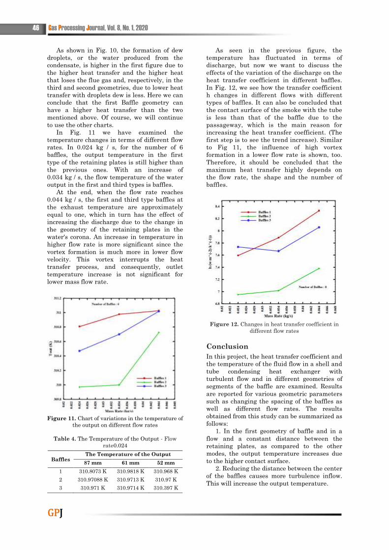
In Fig. 11 we have examined the
temperature changes in terms of different flow
rates. In 0.024 kg / s, for the number of 6
baffles, the output temperature in the first
type of the retaining plates is still higher than
the previous ones. With an increase of
0.034 kg / s, the flow temperature of the water
output in the first and third types is baffles.
At the end, when the flow rate reaches
0.044 kg / s, the first and third type baffles at
the exhaust temperature are approximately
equal to one, which in turn has the effect of
increasing the discharge due to the change in
the geometry of the retaining plates in the
water's corona. An increase in temperature in
higher flow rate is more significant since the
vortex formation is much more in lower flow
velocity. This vortex interrupts the heat
transfer process, and consequently, outlet
temperature increase is not significant for
lower mass flow rate.
Figure 11. Chart of variations in the temperature of
the output on different flow rates
Table 4. The Temperature of the Output - Flow
rate0.024
Baffles The Temperature of the Output
87 mm 61 mm 52 mm
1 310.8073 K 310.9818 K 310.968 K
2 310.97088 K 310.9713 K 310.97 K
3 310.971 K 310.9714 K 310.397 K
As seen in the previous figure, the
temperature has fluctuated in terms of
discharge, but now we want to discuss the
effects of the variation of the discharge on the
heat transfer coefficient in different baffles.
In Fig. 12, we see how the transfer coefficient
h changes in different flows with different
types of baffles. It can also be concluded that
the contact surface of the smoke with the tube
is less than that of the baffle due to the
passageway, which is the main reason for
increasing the heat transfer coefficient. (The
first step is to see the trend increase). Similar
to Fig 11, the influence of high vortex
formation in a lower flow rate is shown, too.
Therefore, it should be concluded that the
maximum heat transfer highly depends on
the flow rate, the shape and the number of
baffles.
Figure 12. Changes in heat transfer coefficient in
different flow rates
Conclusion
In this project, the heat transfer coefficient and
the temperature of the fluid flow in a shell and
tube condensing heat exchanger with
turbulent flow and in different geometries of
segments of the baffle are examined. Results
are reported for various geometric parameters
such as changing the spacing of the baffles as
well as different flow rates. The results
obtained from this study can be summarized as
follows:
1. In the first geometry of baffle and in a
flow and a constant distance between the
retaining plates, as compared to the other
modes, the output temperature increases due
to the higher contact surface.
2. Reducing the distance between the center
of the baffles causes more turbulence inflow.
This will increase the output temperature.
Simulation and CFD Analyses of Condensing Shell and Tube Heat Exchanger for CHP Package Application 47
GPJ
3. Increase the amount of flow from 0.024 to
0.034 and then 0.044 kg/s in a constant
distance of the baffle, causes the increment for
coefficient.
4. The formation of dew droplets, or the
water produced from the condensate, is higher
in the first figure due to higher heat transfer
and higher heat losses, which is lower in third
and second geometries, respectively. The main
reason for this event is lower heat transfer
with dewdrops. This means that the first
Baffle geometry can have a higher heat
transfer than the two mentioned above.
Offers
To continue the research, the following options
are suggested:
The use of nanoparticles in heat exchangers
will increase the heat transfer rate. Therefore,
the study on the use of these particles and
their concentration and optimal sex are of
great importance. Experimental study of heat
transfers and flow in shell heat exchangers
and condensation tubes with the mentioned
baffles to verify the numerical studies
performed in this study and available
resources seems necessary. It is recommended
to use a porous medium to eliminate the
reverse flow in the path and to increase the
turmoil to add the transfer of the heat
exchanger.
Reference
Brownea M. W, Bansala P.K, (1999), An
overview of condensation heat transfer
on horizontal tube bundles, Applied
Thermal Engineering, 19, 565-594.
Osakabe M, Ishida K, Yagi K, Itoh T, Ohmasa
K, (2001), Condensation heat transfer
on tubes in actual flue gas , Heat
Transfer Asian Research 30, 139–151.
Jia L, Peng X. F, Sun J.D, Chen T. B, (2001),
An Experimental Study on Vapor
Condensation of Wet Flue Gas in a
Plastic Heat Exchanger, Heat Trans
Asian Res 30(7), 571-580.
Jia L, Peng X. F, Yan Y, Sun J. D, Li X. P,
Effects of water vapor condensation on
the convection heat transfer of wet flue
gas in a vertical tube, International
Journal of Heat and Mass Transfer 44,
4257-4265.
Shi X, Che D, Agnew B, Gao J, (2011) An
investigation of the performance of
compact heat exchanger for latent heat
recovery from exhaust flue gases,
International Journal of Heat and
Mass Transfer 54, 606–615.
Lee S, Kum S. M, Lee C. E, (2011),
Performances of a heat exchanger and
pilot boiler for the development of a
condensing gas boiler, Energy,36,
3945-3951.
Goel N, (2012), Design and Performance
Analyses of Condensing Heat
Exchangers for Recovering Water and
Waste Heat from Flue Gas, A Thesis of
Lehigh University, Paper 1164.
Wang Y, Zhao Q, Zhou Q, Kang Z, Tao W,
(2013), Experimental and numerical
studies on actual flue gas condensation
heat transfer in a left–right symmetric
internally finned tube, International
Journal of Heat and Mass Transfer,
64, 10–20.
Lin C. X, Wang D, Bao A, (2013), Numerical
modeling and simulation of
condensation heat transfer of a flue
gas in a bundle of transport membrane
tubes, International Journal of Heat
and Mass Transfer, 60, 41–50.
Soleimani S, Lin C. X, Wang D, (2015),
Numerical Modeling of Industrial
Scale Transport Membrane Condenser
Based Heat Exchanger for Flue Gas
Waste Heat and Water Recovery,
IMECE November 13-19, Houston,
Texas, 52324.
Soleimani S, Lin C. X, Wang D, (2016),
Numerical Investigation of Heat
Transfer and Condensation Rate in
Two-Stage Transport Membrane
Condenser Heat Exchanger Units, HT
July, 10-14, Washington, DC, USA,
7291.
Terhan M, Comakli K, (2016), Design and
economic analysis of a flue gas
condenser to recovery latent heat from
exhaust flue gas, Applied Thermal
Engineering, 100, 1007-1015.
Gu H, Chen Q, Zhang Z, Guo H, (2016), Study
of Condensation Flow Patterns and
Heat Transfer Characteristic on a
Horizontal Tube Bundle, IMECE
November 11-17, Phoenix, Arizona,
USA.
Lin C. X, Soheil Soleimani S, Wang D,
Ghasemi E, (2017), Off-Design
Modeling of Shell and Tube Transport
Membranes Condenser Heat
48 Gas Processing Journal, Vol. 8, No. 1, 2020
GPJ
EXxchangers, IMECE November 3-9,
Tampa, Florida, USA-72495.
Zhao S, Yan S, Wang D. K, Wei Y, Qi H, Wu T,
Feron P. H. M, (2017), Simultaneous
heat and water recovery from flue gas
by membrane condensation:
Experimental investigation, Applied
Thermal Engineering 113, 843–850.
Cao W, You X, (2017), Effects of Wall Fins
Patterns on the Flue Gas Performance
of Condensing Heat Exchanger,
Science Direct Procedia Engineering
205, 2281–2288.
Yin Z, Guo Y, Sunden B, Wang Q, Zeng M,
(2015), Numerical Simulation of
Laminar Film Condensation in a
Horizontal Mini-tube with and
Without Non-Condensable Gas by the
VOF Method, An International
Journal of Computation and
Methodology, 68:9, 958-977.
Chen H, Zhou Y, Cao S, Li X, Su X, An L, Gao
D, (2017), Heat exchange and water
recovery experiments of flue gas with
using Nano-porous ceramic
membranes, Applied Thermal
Engineering, 110, 686-694.


![M DÉLISATION DES PLASMAS D’ARCjrpf2014.sciencesconf.org/conference/jrpf2014/pages/Bauchire.pdf · Quelques exemples Arc de coupure (3D, temporel, laminaire, ANSYS Fluent®) [5]](https://img.pdfslide.fr/doc/110x75/5e4b706b90cf8e6a180d1171/m-dlisation-des-plasmas-da-quelques-exemples-arc-de-coupure-3d-temporel-laminaire.jpg)