Embed Size (px)
Citation preview
Euro PM2015 – Compaction & Lubricants
PresentedatEUROPM2015inReims,France Page1
High green strength materials for low density applications like shock absorber parts and self-lubricating bearings
Caroline Larsson (Höganäs Sweden AB, 263 83 Höganäs, Sweden) [email protected] Peter Johansson (Höganäs Sweden AB, 263 83 Höganäs, Sweden) [email protected] Abstract Shock absorber parts like pistons, cylinder ends and rod guides are multi-level parts with rather complex geometry. These are preferably produced by means of PM due to their net shape and design freedom, in combination with the dimensional precision that is a critical requirement. The demand on sintered strength is not so high why the Fe+Cu+C system is mainly used with densities typically in the range of 6.3-6.7 g/cm3. The relatively low density in combination with the complex geometries and the demand for dimensional accuracy, make the sponge iron powders a natural choice. A new lubricant and mix system has been developed in order to improve dimensional stability and especially green strength even further. This system, Intralube S, is tailored to work with sponge powders at low densities. It is a Zn-free and environmentally friendly system. Introduction The first sponge iron process was invented by Sieurin [1] at Höganäs in 1908. Iron ore, concentrated magnetite from northern Sweden, was reduced in solid state using coal from local mines in Höganäs. The method has been in use in industrial scale since 1911. Initially the sponge iron was used as a high purity melting stock for the production of basic electric steel and for production of acid open-heart steel. For the latter, 12-25% of sponge iron was used in the charge [2]. Later on in 1947 a factory was built for production of sponge iron powder. A sister company was founded in 1950, Swedish Sponge Iron and Metal Powder Corporation in Riverton, USA (name later changed to Hoeganaes Corporation and today GKN Hoeganaes). Today this type of sponge powder is only produced at the original site in Höganäs.
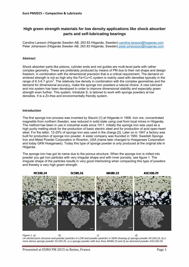
The sponge iron has got its name due to the porous structure. When the sponge iron is milled into powder you get iron particles with very irregular shape and with inner porosity, see figure 1. The irregular shape of the particles results in very good interlocking when compacting this type of powders and thereby a very high green strength.
Figure 1. a) b) c) d) Un-etched pore structure and powder particles in LOM and powder particles in SEM showing a) sponge powder NC100.23, b) a more dense sponge powder SC100.26, c) a sponge powder with less fines MH80.23 and d) an atomized powder ASC100.29.
Euro PM2015 – Compaction & Lubricants
PresentedatEUROPM2015inReims,France Page2
The sponge powders have for decades been the natural choice for PM applications like self-lubricating bearings and shock absorber parts like pistons and rod guides. The main reason is the high green strength that is achieved already at low densities. The development trend of the shock absorber parts goes toward lower densities and complex parts with more intricate shapes and decreased wall thickness, making this even more critical.
The development work in the field of sponge iron powders have been quite limited. Efforts have been made to produce “sponge-like” powders by melting and atomizing, but critical properties like green strength has not been possible to match. In this work the ambition has been to improve the green strength of sponge powder mixes even further, together with improved filling for better dimensional accuracy.
Experiments
Three different lubricants have been used in the investigations presented in this paper. A newly developed lubricant, Lube S, is compared to Zn-Stearate and Amide Wax. These have been mixed with the most frequently used sponge powder NC100.24 together with 2% atomized Cu -100 and 0.5% natural graphite UF4, corresponding to MPIF standard FC0205. The lubricant content of Lube S has been varied in the range of 0.4-1.0%, see table 1, whereas the Zn-stearate and Amide Wax were added with 0.8%.
In the second run mixes were also prepared using the base powder SC100.26, which is a sponge powder with higher apparent density (AD), and the MH80.23 powder with lower AD due to the lower amount of fine particles. All mixes have been produced as lab scale mixes. Flow and AD have been evaluated using the Gustavsson method (ISO 13517:2013). Green density (GD) was measured according to ISO 3927-1985 at compacting pressures of 250, 400 and 550 MPa. The green strength (GS) measured according to ISO 3995-1985 was evaluated at a fixed density level of 6.4 g/cm3. Ejection energy and ejection force were measured on GD-specimens compacted at 400 MPa.
Mix Sponge Lubricant Lubricant Cu C
number powder type amount ‐100 UF4
% % %
1 NC100.24 Lube S 0,4 2,0 0,5
2 NC100.24 Lube S 0,6 2,0 0,5
3 NC100.24 Lube S 0,8 2,0 0,5
4 NC100.24 Lube S 1,0 2,0 0,5
5 NC100.24 Zn‐st 0,8 2,0 0,5
6 NC100.24 A‐wax 0,8 2,0 0,5
5 NC100.24 Lube S 0,8 2,0 0,5
7 SC100.26 Lube S 0,8 2,0 0,5
8 MH80.23 Lube S 0,8 2,0 0,5 Table 1. Mix compositions for lab experiments
Compaction and sintering trials on shock absorber rod guides have been done in production at Polmo Łomianki S.A. comparing 2 different mixes. The reference mix, produced in production scale, is based on NC100.24 and is using Zn-stearate as lubricant with an addition of 0.8 %, see table 2. The AD of this mix is rather high as the lubricant is a metal stearate. The test mix A was a 1 tonne mix produced in lab scale with 0.8 % Lube S as lubricant. An addition of 25% SC100.26 was made in order to adjust the apparent density of the mix. This was required as an existing tool was used for the trials. The mixes also contains an addition of 1.2 % natural graphite UF4. Mix properties like AD, Flow and GD were measured according to standards mentioned above. Green density was measured at a compacting pressure of 600 MPa.
Euro PM2015 – Compaction & Lubricants
PresentedatEUROPM2015inReims,France Page3
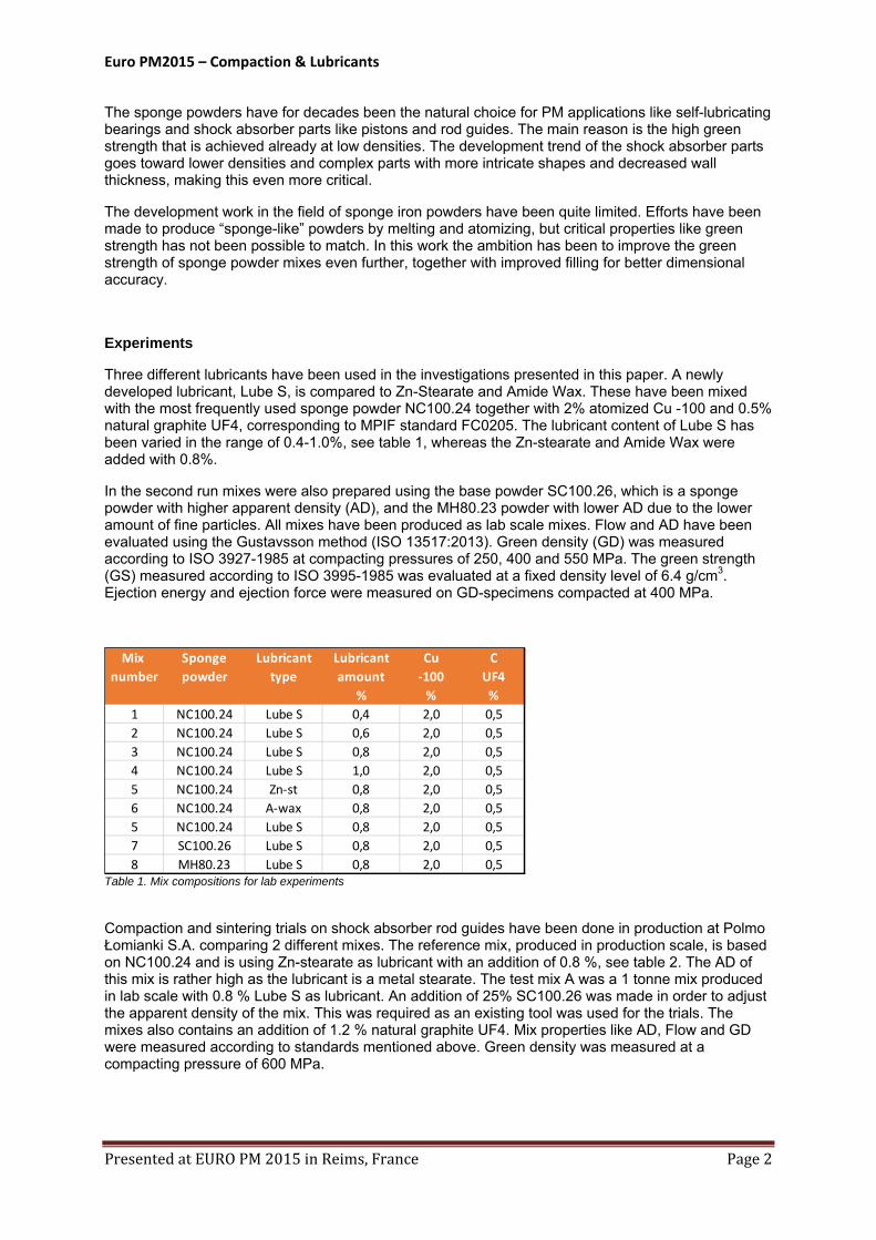
Mixes Ref. A
NC100.24 Bal. Bal.
SC100.26 ‐ 25%
C UF4 1,2% 1,2%
Zn‐st 0,8% ‐
Lube S ‐ 0,8% Table 2. Mix compositions for production experiments Figure 2. Green rod guides
The compaction was run at 20.1 strokes per minute for the reference mix. The test mix A was run at both 20.1 and 22.6 strokes per minute. The part temperature was measured directly after ejection and the weight and dimensional tolerance were controlled. The production trials run for about 1000 parts per mix. Green strength was measured as radial crushing strength on the rod guides both at Polmo and at Höganäs. Sintering was done at 1120⁰C in a production belt furnace using Endo-gas.
Results of lab experiments
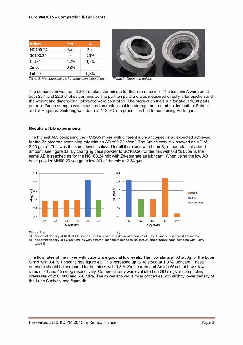
The highest AD, comparing the FC0205 mixes with different lubricant types, is as expected achieved for the Zn-stearate containing mix with an AD of 2.72 g/cm3. The Amide Wax mix showed an AD of 2.50 g/cm3. This was the same level achieved for all the mixes with Lube S, independent of added amount, see figure 3a. By changing base powder to SC100.26 for the mix with 0.8 % Lube S, the same AD is reached as for the NC100.24 mix with Zn-stearate as lubricant. When using the low AD base powder MH80.23 you get a low AD of the mix at 2.34 g/cm3.
Figure 3. a) b) a) Apparent density of NC100.24 based FC0205 mixes with different amounts of Lube S and with different lubricants b) Apparent density of FC0205 mixes with different lubricants added to NC100.24 and different base powders with 0,8%
Lube S
The flow rates of the mixes with Lube S are good at low levels. The flow starts at 36 s/50g for the Lube S mix with 0.4 % lubricant, see figure 4a. This increased up to 38 s/50g at 1.0 % lubricant. These numbers should be compared to the mixes with 0,8 % Zn-stearate and Amide Wax that have flow rates of 41 and 45 s/50g respectively. Compressibility was evaluated on GD-slugs at compacting pressures of 250, 400 and 550 MPa. The mixes showed similar properties with slightly lower density of the Lube S mixes, see figure 4b.
Euro PM2015 – Compaction & Lubricants
PresentedatEUROPM2015inReims,France Page4
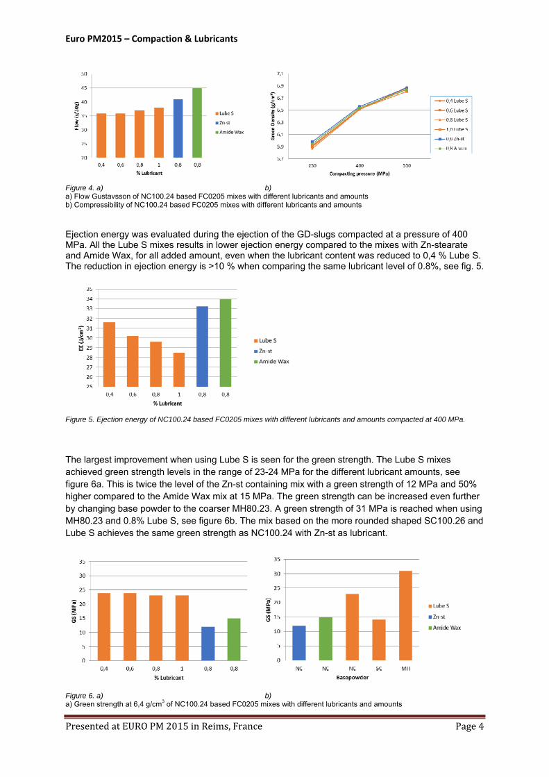
Figure 4. a) b) a) Flow Gustavsson of NC100.24 based FC0205 mixes with different lubricants and amounts b) Compressibility of NC100.24 based FC0205 mixes with different lubricants and amounts
Ejection energy was evaluated during the ejection of the GD-slugs compacted at a pressure of 400 MPa. All the Lube S mixes results in lower ejection energy compared to the mixes with Zn-stearate and Amide Wax, for all added amount, even when the lubricant content was reduced to 0,4 % Lube S. The reduction in ejection energy is >10 % when comparing the same lubricant level of 0.8%, see fig. 5.
Figure 5. Ejection energy of NC100.24 based FC0205 mixes with different lubricants and amounts compacted at 400 MPa.
The largest improvement when using Lube S is seen for the green strength. The Lube S mixes achieved green strength levels in the range of 23-24 MPa for the different lubricant amounts, see figure 6a. This is twice the level of the Zn-st containing mix with a green strength of 12 MPa and 50% higher compared to the Amide Wax mix at 15 MPa. The green strength can be increased even further by changing base powder to the coarser MH80.23. A green strength of 31 MPa is reached when using MH80.23 and 0.8% Lube S, see figure 6b. The mix based on the more rounded shaped SC100.26 and Lube S achieves the same green strength as NC100.24 with Zn-st as lubricant.
Figure 6. a) b) a) Green strength at 6,4 g/cm3 of NC100.24 based FC0205 mixes with different lubricants and amounts
Euro PM2015 – Compaction & Lubricants
PresentedatEUROPM2015inReims,France Page5
b) Green strength at 6,4 g/cm3 of FC0205 mixes with different lubricants and base powders Results of production experiments
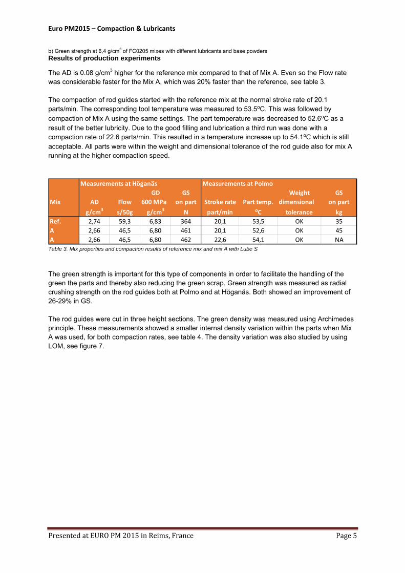
The AD is 0.08 g/cm3 higher for the reference mix compared to that of Mix A. Even so the Flow rate was considerable faster for the Mix A, which was 20% faster than the reference, see table 3. The compaction of rod guides started with the reference mix at the normal stroke rate of 20.1 parts/min. The corresponding tool temperature was measured to 53.5⁰C. This was followed by
compaction of Mix A using the same settings. The part temperature was decreased to 52.6⁰C as a result of the better lubricity. Due to the good filling and lubrication a third run was done with a compaction rate of 22.6 parts/min. This resulted in a temperature increase up to 54.1⁰C which is still acceptable. All parts were within the weight and dimensional tolerance of the rod guide also for mix A running at the higher compaction speed.
Measurements at Höganäs Measurements at Polmo
GD GS Weight GS
Mix AD Flow 600 MPa on part Stroke rate Part temp. dimensional on part
g/cm3 s/50g g/cm3 N part/min ⁰C tolerance kg
Ref. 2,74 59,3 6,83 364 20,1 53,5 OK 35
A 2,66 46,5 6,80 461 20,1 52,6 OK 45
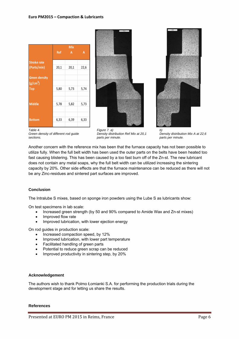
A 2,66 46,5 6,80 462 22,6 54,1 OK NA Table 3. Mix properties and compaction results of reference mix and mix A with Lube S The green strength is important for this type of components in order to facilitate the handling of the green the parts and thereby also reducing the green scrap. Green strength was measured as radial crushing strength on the rod guides both at Polmo and at Höganäs. Both showed an improvement of 26-29% in GS. The rod guides were cut in three height sections. The green density was measured using Archimedes principle. These measurements showed a smaller internal density variation within the parts when Mix A was used, for both compaction rates, see table 4. The density variation was also studied by using LOM, see figure 7.
Euro PM2015 – Compaction & Lubricants
PresentedatEUROPM2015inReims,France Page6
Ref A A
Stroke rate
(Parts/min) 20,1 20,1 22,6
Green density
(g/cm3)
Top 5,80 5,73 5,74
Middle 5,78 5,82 5,73
Bottom 6,33 6,39 6,33
Mix
Table 4. Figure 7. a) b) Green density of different rod guide Density distribution Ref Mix at 20,1 Density distribution Mix A at 22,6 sections. parts per minute. parts per minute. Another concern with the reference mix has been that the furnace capacity has not been possible to utilize fully. When the full belt width has been used the outer parts on the belts have been heated too fast causing blistering. This has been caused by a too fast burn off of the Zn-st. The new lubricant does not contain any metal soaps, why the full belt width can be utilized increasing the sintering capacity by 20%. Other side effects are that the furnace maintenance can be reduced as there will not be any Zinc-residues and sintered part surfaces are improved. Conclusion
The Intralube S mixes, based on sponge iron powders using the Lube S as lubricants show:
On test specimens in lab scale: Increased green strength (by 50 and 90% compared to Amide Wax and Zn-st mixes) Improved flow rate Improved lubrication, with lower ejection energy
On rod guides in production scale: Increased compaction speed, by 12% Improved lubrication, with lower part temperature Facilitated handling of green parts Potential to reduce green scrap can be reduced Improved productivity in sintering step, by 20%
Acknowledgement
The authors wish to thank Polmo Łomianki S.A. for performing the production trials during the development stage and for letting us share the results.
References
Euro PM2015 – Compaction & Lubricants
PresentedatEUROPM2015inReims,France Page7
1. E Sieurin, “Experiments in producing sponge iron in Höganäs” Blad för Bergshanteringens vänner, vol 13, 1911, p195
2. M. Tigerschiöld, S. Eketorp, ”The Use of Sponge Iron for Steel Production” METALLURGIA, Vol. 37, 1948, p. 170