Embed Size (px)
Citation preview
Impact of an internal polymeric liner on the fatigue strength of pressure
vessels under internal pressure
M.A. Bennani a,*, Abdeslam El Akkad b, Ahmed Elkhalfi a a Facultée des Sciences et Techniques de Fès, Maroc.
b
Département de mathématiques, Centre Régional des Métiers d’Education et de Formation Fès, Maroc.
Abstract
This paper presents a new original idea about the fatigue strength of pressure vessels. It tries to examine the impact of the internal liner
on the fatigue strength of pressure vessels. The liner is mainly used to protect the structure against corrosive products such as hydrocarbons.
This study states that the installation of a super-elastic polymer coating can help to solve several problems related to pressure vessels. In
addition to the protection against corrosion, this coating may contribute to the improvement of the fatigue strength of structures as well as
the prevention of sudden leaks. Moreover, this paper has proposed two main examinations; the first is an attempt to compare different
susceptible materials used as liners. Besides, parametric study is performed during the second examination with the previously selected material for the optimal thickness.
Keywords: pressure vessel; fatigue analysis; liner; coating; failure.
Introduction
Pressure vessels are widely used in industry for the
storage and transport of liquids or gases. They can be
defined as devices that work beyond atmospheric
pressure. In the 19th century, the world experienced an
unprecedented industrial revolution that conduced to the
mass production of pressure vessels (tank, boiler ... etc.).
These devices were dangerous and caused several
damages. As consequently, it caused the legalization of
regulatory and specialized standard for pressure vessels.
While the most important are, the American Society of
Mechanical Engineers (ASME-1915) and the Code for
the Construction of Pressure Vessels not subject to the
flame (CODAP). The pressure vessels are subject to
several types of chemical or mechanical damage such as
corrosion. The installation of internal liner functions as
protection against the corrosive effect and warn leakage.
Pressure tanks are affected by some problems today
despite the strict regulations undertaken recently. Many
industrial incidents are caused by explosions of tanks
containing flammable or leakage of petroleum products
offshore, destroying ecological systems. Most of these
structures have not been damaged due to under-sizing or
poor design, but because of fatigue problems, which
amplifies the presence of residual crack and lack of
maintenance that sometimes are expensive or
complicated. High cycle fatigue loading is one of the main
mechanism that may lead to damage in pressure vessels,
because damage occurs without exceeding the elastic
limit. Theatrically speaking, the structure endures these
charges, as they do not exceed the elastic limit, while in
spite of the fact that these charges do not exceed this limit,
the structure can undergo large damage due to fatigue.
This paper presents a study on the use of liner to
increase the fatigue strength of pressure vessels. We
propose to investigate the mechanical impact of the liner
and its durability against chemical attacks and other
destructive phenomena.
The first part of the article provides the theoretical
framework and the practical analysis to the phenomena
and the tools used in this study. The second part presents
the numerical model to assess the effectiveness of the
method.
Pressure vessel liners-literature review
The liner is used in a large number of pressure vessels to
protect metal structures against corrosion, but it is used in
its metallic version in tanks and pipeline composite to seal
the structure. This section presents some studies on topics
concerning the liner or any related topic. A several
scientific studies have dealt with the subject of the liner
directly or indirectly. They study its mechanical impact,
chemical or, in some cases, its use in the cured-in-place
pipe (CIPP) for damaged pipelines.
A. Hocine et al. [1] conducted an investigative study
on the type of materials used for the liner for composite
cylinder with an internal liner. The study compares the
resistance of three types of internal pressure to liner. The
studied materials are HDPE (High Density Polyethylene),
LLDPE (Light Polyethylene Low Density) and the
combination of these two materials HDPE / LLDPE.
Article approves the resistance of HDPE to high pressure
by comparing it with other liners. F. Rueda et al. [2]
conducted a study on recurring problem liners, including
wrinkles and damage in the structure of the liner. The
author points to the rapid depressurization as the main
cause of the folds of the liner. He presents and uses a
numerical model based on the method of unconventional
finite elements, allowing the use of material law time-
dependent behavior. Evoking the difficulty of
reproducing the fold of the liner due to non-linear aspect,
the material used is again HDPE (High density
Polyethylene).
WSEAS TRANSACTIONS on APPLIED and THEORETICAL MECHANICSM. A. Bennani,
Abdeslam El Akkad, Ahmed Elkhalfi
E-ISSN: 2224-3429 67 Volume 11, 2016
Y.T. Kim et al.[3] resents a comprehensive study on
the impact of a cracked cylinder liner, which undergoes
pure buckling forces and combines internal pressure; they
uses the finite element method to evaluate the stress at the
crack tip. In addition, he conducted a parametric study to
analyze the effect of the thickness of the liner and the
effect of the size and the orientation of the crack on the
buckling strength of the cylinder. We have deduced that
the liner significantly improves buckling characteristics
of a shell and one notes the influence of the thickness of
the liner on the behavior of our thin cylindrical shell. On
the other hand, it demonstrates the absence of the impact
of circumferential cracks on the structure, but also the
discovery of a low impact of a crack oriented at 30 °.
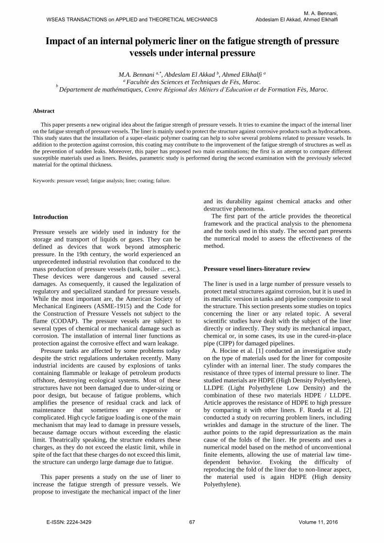
Fig. 1. corroded pipe
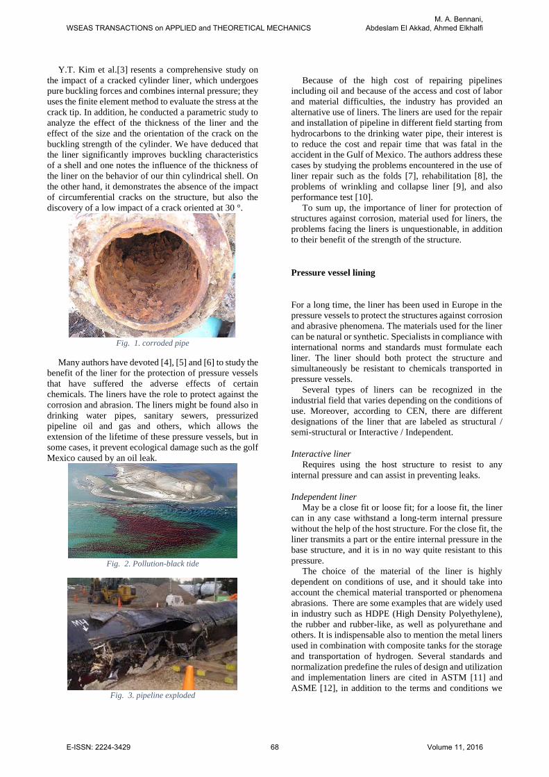
Many authors have devoted [4], [5] and [6] to study the
benefit of the liner for the protection of pressure vessels
that have suffered the adverse effects of certain
chemicals. The liners have the role to protect against the
corrosion and abrasion. The liners might be found also in
drinking water pipes, sanitary sewers, pressurized
pipeline oil and gas and others, which allows the
extension of the lifetime of these pressure vessels, but in
some cases, it prevent ecological damage such as the golf
Mexico caused by an oil leak.
Fig. 2. Pollution-black tide
Fig. 3. pipeline exploded
Because of the high cost of repairing pipelines
including oil and because of the access and cost of labor
and material difficulties, the industry has provided an
alternative use of liners. The liners are used for the repair
and installation of pipeline in different field starting from
hydrocarbons to the drinking water pipe, their interest is
to reduce the cost and repair time that was fatal in the
accident in the Gulf of Mexico. The authors address these
cases by studying the problems encountered in the use of
liner repair such as the folds [7], rehabilitation [8], the
problems of wrinkling and collapse liner [9], and also
performance test [10].
To sum up, the importance of liner for protection of
structures against corrosion, material used for liners, the
problems facing the liners is unquestionable, in addition
to their benefit of the strength of the structure.
Pressure vessel lining
For a long time, the liner has been used in Europe in the
pressure vessels to protect the structures against corrosion
and abrasive phenomena. The materials used for the liner
can be natural or synthetic. Specialists in compliance with
international norms and standards must formulate each
liner. The liner should both protect the structure and
simultaneously be resistant to chemicals transported in
pressure vessels.
Several types of liners can be recognized in the
industrial field that varies depending on the conditions of
use. Moreover, according to CEN, there are different
designations of the liner that are labeled as structural /
semi-structural or Interactive / Independent.
Interactive liner
Requires using the host structure to resist to any
internal pressure and can assist in preventing leaks.
Independent liner
May be a close fit or loose fit; for a loose fit, the liner
can in any case withstand a long-term internal pressure
without the help of the host structure. For the close fit, the
liner transmits a part or the entire internal pressure in the
base structure, and it is in no way quite resistant to this
pressure.
The choice of the material of the liner is highly
dependent on conditions of use, and it should take into
account the chemical material transported or phenomena
abrasions. There are some examples that are widely used
in industry such as HDPE (High Density Polyethylene),
the rubber and rubber-like, as well as polyurethane and
others. It is indispensable also to mention the metal liners
used in combination with composite tanks for the storage
and transportation of hydrogen. Several standards and
normalization predefine the rules of design and utilization
and implementation liners are cited in ASTM [11] and
ASME [12], in addition to the terms and conditions we
WSEAS TRANSACTIONS on APPLIED and THEORETICAL MECHANICSM. A. Bennani,
Abdeslam El Akkad, Ahmed Elkhalfi
E-ISSN: 2224-3429 68 Volume 11, 2016
can calculate the minimum and maximum thickness of the
liner.
Fatigue of pressure vessels.
We consider fatigue as the biggest cause of damage of the
pressure vessels; consequently, design codes list several
rules to follow when designing, manufacturing and using
the pressure vessels.
The fatigue damage may be the result of a cyclic
loading or thermal. It is recommended by many design
codes to use the concept of the endurance limit in the
design of pressure vessels. This concept is defined as the
stress limit that applied to this structure so that it can
support an infinite number of cycle; often the number of
cycles is limited to 107 cycles.
Generally, there are two types of fatigue, high cycle
fatigue and low cycle fatigue. The low cycle fatigue
requires a lower cycle number and involves excessive
deformation, and it is strongly related to plastic
deformation in the material. The fatigue study in the case
of low cycle fatigue is based on the number-strain curves
cycle. For high cycle fatigue, it produces a large number
of cycles, and damage may occur due to a lower loading
than the elastic limit of the material. In fact, there are still
plastic deformation at the microscopic scale. Based on
this case, we use stress-cycle curves for the fatigue study.
In general, fatigue damage is the result of many causes
that are related to materials as inclusion or imperfections
that are the zones of the initiation and propagation of
crack by fatigue. Moreover, geometry is also concerned
to be a major cause of fatigue as the case of its sudden
change that causes stress concentration, which makes of
fatigue damage inevitable.
The fatigue study of pressure vessels is based on the
use of Tresca criteria, taking into account the maximum
shear stress in addition to the rules of Miner's [13] to
estimate the cumulative damage due to cyclic loading. For
the stress concentrations, it is advisable to use the
theoretical stress concentration factors [14] to analyze the
effect of the geometry of the structure of behavior, as well
as [15] for pressure vessels is strictly forbidden to
approach the value of 5 for stress concentration factors, in
some cases this value should not exceed 4.
Specific rules for pressure vessels, which undergo
cyclic loads, are established by Langer [16]. Langer has
established six rules that take into consideration the load
fluctuations, temperature changes, and other parameters
such as the type of material and the factors of stress
concentrations. They do not exceed the value of 2 when
the nominal stress equals 3SM (sm is called stress
intensity as per ASME design, usually equal to 2/3 of the
yield strength).
Lined pressure vessel model
Each pressure vessel must comply during its design the
standard instructions. For this reason, it is planned to be
taken as an example to study a pressure vessel designed
according to international standards and meets safety
standards.
Our goal is to study the impact of a liner on the fatigue
strength of a pressure vessel. For this reason, we chose to
make numerical simulations and use all the techniques
available to assess the parameters that influences our
model. The aim is to numerically evaluate fatigue in the
model in two particular cases; the first one is a standard
pressure equipment, on which cyclic loading will be
applied, simulating the conditions of use for the entire life
of the product, and the second case is a pressure vessel
with a liner, which subjected to the same conditions.
We have opted to study steel pressure vessel, and for
the liner, we have chosen an interactive liner type
(section), whose material that respects the operating
conditions (i.e. the protection of corrosion) is elastomeric.
We will focus on fatigue study of steel cylinder, fatigue
liner itself is not considered. It is assumed in the study that
the bonding between the two bodies is permanent and
indestructible.
A parametric study has been conducted to find the best
liner thickness taken as reference to the thickness of the
shell, and then the thickness of the liner would be 50%,
75%, 100% or even 200% of the thickness of the shell.
Pressue vessel data
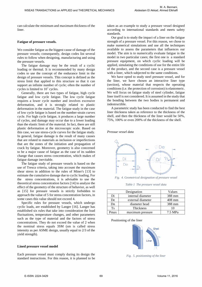
Fig. 4. Geometrical designation of pressure vessel
Table 1 The pressure vessel data
Designation Values
Di internal diameter 388 mm
De external diameter 408 mm
Dn diameter head 388 mm
Ts Thickness 10
Pmax maximum pressure 7.5 MPa
Positioning of the liner
Fig. 5. positionning of the liner
WSEAS TRANSACTIONS on APPLIED and THEORETICAL MECHANICSM. A. Bennani,
Abdeslam El Akkad, Ahmed Elkhalfi
E-ISSN: 2224-3429 69 Volume 11, 2016
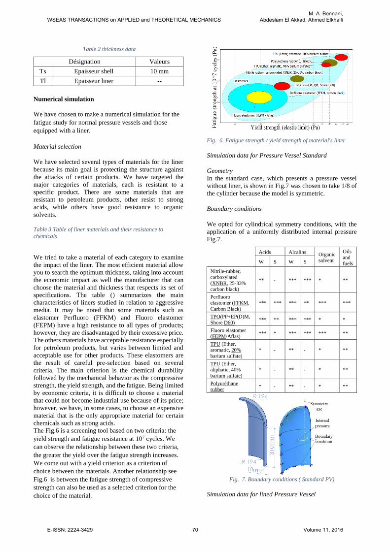
Table 2 thickness data
Numerical simulation
We have chosen to make a numerical simulation for the
fatigue study for normal pressure vessels and those
equipped with a liner.
Material selection
We have selected several types of materials for the liner
because its main goal is protecting the structure against
the attacks of certain products. We have targeted the
major categories of materials, each is resistant to a
specific product. There are some materials that are
resistant to petroleum products, other resist to strong
acids, while others have good resistance to organic
solvents.
Table 3 Table of liner materials and their resistance to
chemicals
We tried to take a material of each category to examine
the impact of the liner. The most efficient material allow
you to search the optimum thickness, taking into account
the economic impact as well the manufacturer that can
choose the material and thickness that respects its set of
specifications. The table () summarizes the main
characteristics of liners studied in relation to aggressive
media. It may be noted that some materials such as
elastomer Perfluoro (FFKM) and Fluoro elastomer
(FEPM) have a high resistance to all types of products;
however, they are disadvantaged by their excessive price.
The others materials have acceptable resistance especially
for petroleum products, but varies between limited and
acceptable use for other products. These elastomers are
the result of careful pre-selection based on several
criteria. The main criterion is the chemical durability
followed by the mechanical behavior as the compressive
strength, the yield strength, and the fatigue. Being limited
by economic criteria, it is difficult to choose a material
that could not become industrial use because of its price;
however, we have, in some cases, to choose an expensive
material that is the only appropriate material for certain
chemicals such as strong acids.
The Fig.6 is a screening tool based on two criteria: the
yield strength and fatigue resistance at 107 cycles. We
can observe the relationship between these two criteria,
the greater the yield over the fatigue strength increases.
We come out with a yield criterion as a criterion of
choice between the materials. Another relationship see
Fig.6 is between the fatigue strength of compressive
strength can also be used as a selected criterion for the
choice of the material.
Fig. 6. Fatigue strength / yield strength of material's liner
Simulation data for Pressure Vessel Standard
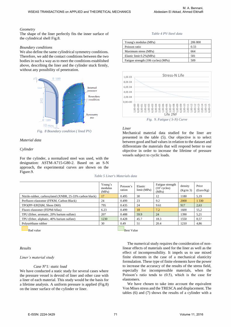
Geometry
In the standard case, which presents a pressure vessel
without liner, is shown in Fig.7 was chosen to take 1/8 of
the cylinder because the model is symmetric.
Boundary conditions
We opted for cylindrical symmetry conditions, with the
application of a uniformly distributed internal pressure
Fig.7.
Fig. 7. Boundary conditions ( Standard PV)
Simulation data for lined Pressure Vessel
Désignation Valeurs
Ts Epaisseur shell 10 mm
Tl Epaisseur liner --
Acids Alcalins Organic
solvent
Oils and
fuels W S W S
Nitrile-rubber, carboxylated
(XNBR, 25-33% carbon black)
** - *** *** * **
Perfluoro elastomer (FFKM,
Carbon Black) *** *** *** ** *** ***
TPO(PP+EP(D)M, Shore D60)
*** ** *** *** * *
Fluoro elastomer (FEPM/Aflas)
*** * *** *** *** **
TPU (Ether, aromatic, 20%
barium sulfate) * - ** - * **
TPU (Ether, aliphatic, 40%
barium sulfate) * - ** - * **
Polyuréthane rubber
* - ** - * **
WSEAS TRANSACTIONS on APPLIED and THEORETICAL MECHANICSM. A. Bennani,
Abdeslam El Akkad, Ahmed Elkhalfi
E-ISSN: 2224-3429 70 Volume 11, 2016
Geometry
The shape of the liner perfectly fits the inner surface of
the cylindrical shell Fig.8.
Boundary conditions
We also define the same cylindrical symmetry conditions.
Therefore, we add the contact conditions between the two
bodies in such a way as to meet the conditions established
above, describing the liner and the cylinder stuck firmly,
without any possibility of penetration.
Fig. 8 Boundary condition ( lined PV)
Material data
Cylinder
For the cylinder, a normalized steel was used, with the
designation: ASTM-A715-G80-2. Based on an S-N
approach, the experimental curves are shown on the
Figure.9.
Table 4 PV-Steel data
Young's modulus (MPa) 206 800
Poisson ratio 0.33
Maximum stress (MPa) 664
Elastic limit 0.2%(MPa) 581
Fatigue strength (106 cycles) (MPa) 509
Fig. 9. Fatigue ( S-N) Curve
Liner
Mechanical material data studied for the liner are
presented in the table (5). Our objective is to select
between good and bad values in relation to the dataset and
differentiate the materials that will respond better to our
objective in order to increase the lifetime of pressure
vessels subject to cyclic loads.
Table 5 Liner's Materials data
Results
Liner’s material study
Case N°1: static load
We have conducted a static study for several cases where
the pressure vessel is devoid of liner and other case with
a liner of each material. This study would be the basis for
a lifetime analysis. A uniform pressure is applied (Fig.8)
on the inner surface of the cylinder or liner.
The numerical study requires the consideration of non-
linear effects of materials used for the liner as well as the
effect of incompressibility. It impels us to use mixed
finite elements in the case of a mechanical elasticity
formulation. These type of finite elements have the power
to increase the accuracy of the results of the stress field,
especially for incompressible materials, when the
Poisson’s ratio tends to (0.5), which is the case for
elastomers.
We have chosen to take into account the equivalent
Von Mises stress and the TRESCA and displacement. The
tables (6) and (7) shows the results of a cylinder with a
0,0E+00
2,0E-04
4,0E-04
6,0E-04
8,0E-04
1,0E-03
1,0
E+0
0
6,0
E+0
0
3,0
E+0
1
2,0
E+0
2
1,0
E+0
3
6,0
E+0
3
3,0
E+0
4
2,0
E+0
5
1,0
E+0
6
6,0
E+0
6
3,0
E+0
7
2,0
E+0
8
1,0
E+0
9
6,0
E+0
9
3,0
E+1
0
2,0
E+1
1
1,0
E+1
2
6,0
E+1
2
3,0
E+1
3
2,0
E+1
4
1,0
E+1
5
6,0
E+1
5
Life 2NF
Stress-N Life
Young’s modulus
(MPa)
Poisson’s ration
Elastic limit (MPa)
Fatigue strength (107 cycles)
(MPa)
density
(Kg/m 3)
Price
(Euro/Kg)
Nitrile-rubber, carboxylated (XNBR, 25-33% carbon black) 17 0.495 30 12 1180 5,19
Perfluoro elastomer (FFKM, Carbon Black) 24 0.499 23 9.2 2000 1 330
TPO(PP+EP(D)M, Shore D60) 795 0.435 24 9.61 917 2,63
Fluoro elastomer (FEPM/Aflas) 6.23 0.499 18 7.2 1600 55,2
TPU (Ether, aromatic, 20% barium sulfate) 207 0.488 59.9 24 1390 5,21
TPU (Ether, aliphatic, 40% barium sulfate) 1230 0.428 45.7 18.3 1550 8,57
Polyuréthane rubber 30 0.49 51 20.4 1210 4,86
Bad value Best Value
WSEAS TRANSACTIONS on APPLIED and THEORETICAL MECHANICSM. A. Bennani,
Abdeslam El Akkad, Ahmed Elkhalfi
E-ISSN: 2224-3429 71 Volume 11, 2016
liner (thickness = 15 mm TL) (TPU <Ether, Aliphatic,
40% Barium sulfate>) and without liner. Other results are
considered in details in the graphs (10) (11).
We notice a decrease of the stresses and the
displacement between the standard case and the case of
the pressure vessel with liner; in both cases, the stress
fields and displacement are located on the cylindrical
section, while on the head section these fields are lowest.
In the case of the pressure vessel with a liner, it is noted
that the stresses in the liner are smaller than the cylinder
while is the opposite for the displacement.
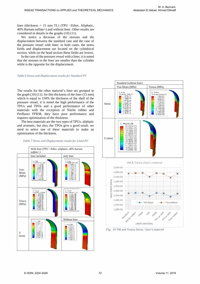
Table 6 Stress and Displacement results for Standard PV
The results for the other material’s liner are grouped in
the graph (10) (11). for this thickness of the liner (15 mm)
which is equal to 150% the thickness of the shell of the
pressure vessel, it is noted the high performance of the
TPUs and TPOs and a good performance of other
materials with the exception of Nitrile rubber and
Perfluoro FFKM, they have poor performance and
requires optimization of the thickness.
The best materials are the two types of TPUs: aliphatic
and aromatic, but also, the TPOs give a good result. we
need to select one of these materials to make an
optimization of the thickness.
Table 7 Stress and Displacement results for Lined PV
Fig. 10 VM and Tresca Stress / liner's material
1,20E+02
1,25E+02
1,30E+02
1,35E+02
1,40E+02
1,45E+02
1,50E+02
1,55E+02
1,60E+02
1,65E+02
MA
X S
TRES
S (M
PA
)
LINER'S MATERIAL
VM & Tresca /liner's material
VM (Mpa) Tresca(Mpa)
Standard (without liner)
Von-Mises (MPa) Tresca (MPa)
Stress
U (mm)
With liner (TPU <Ether, aliphatic, 40% barium
sulfate>)
liner included only liner
Von-Mises
(MPa)
Tresca
(MPa)
U (mm)
Without liner
WSEAS TRANSACTIONS on APPLIED and THEORETICAL MECHANICSM. A. Bennani,
Abdeslam El Akkad, Ahmed Elkhalfi
E-ISSN: 2224-3429 72 Volume 11, 2016
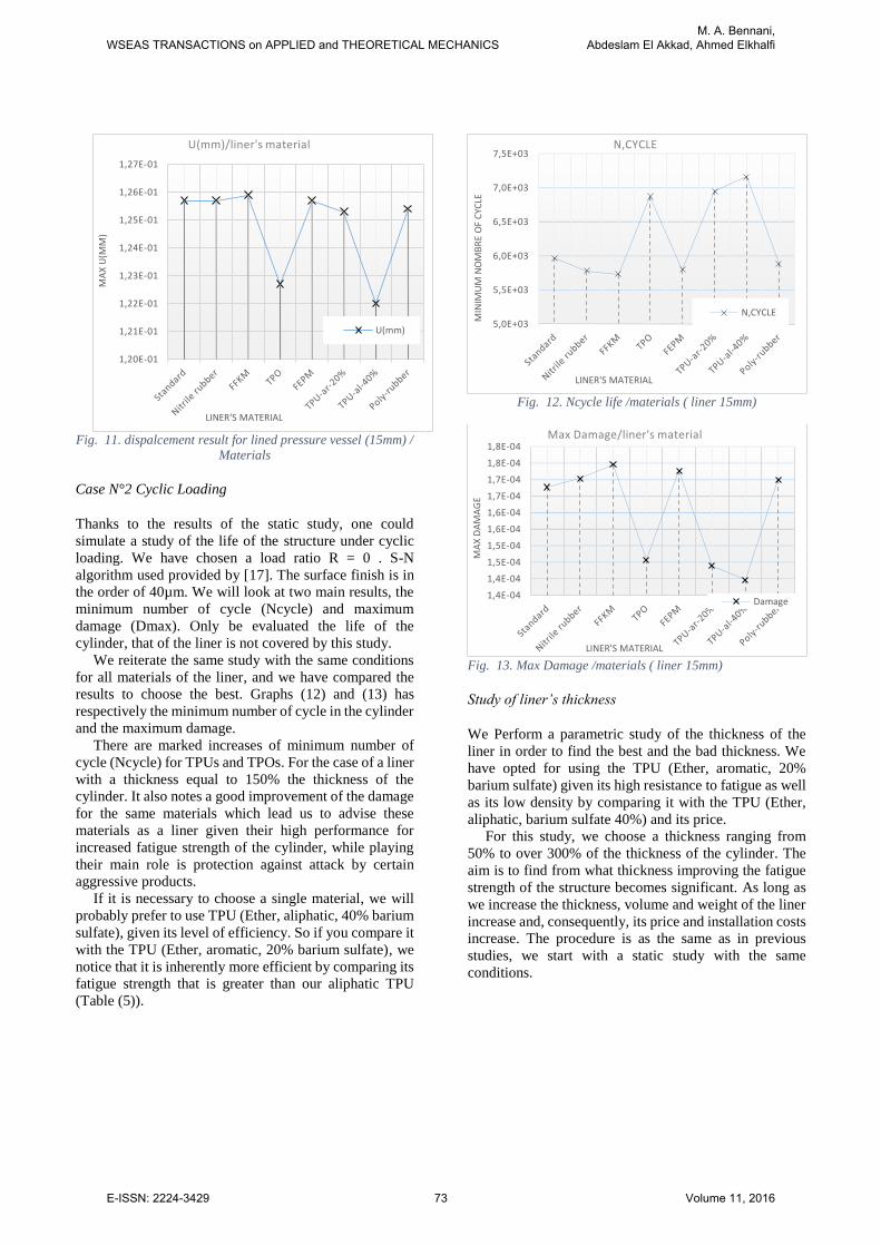
Fig. 11. dispalcement result for lined pressure vessel (15mm) /
Materials
Case N°2 Cyclic Loading
Thanks to the results of the static study, one could
simulate a study of the life of the structure under cyclic
loading. We have chosen a load ratio R = 0 . S-N
algorithm used provided by [17]. The surface finish is in
the order of 40µm. We will look at two main results, the
minimum number of cycle (Ncycle) and maximum
damage (Dmax). Only be evaluated the life of the
cylinder, that of the liner is not covered by this study.
We reiterate the same study with the same conditions
for all materials of the liner, and we have compared the
results to choose the best. Graphs (12) and (13) has
respectively the minimum number of cycle in the cylinder
and the maximum damage.
There are marked increases of minimum number of
cycle (Ncycle) for TPUs and TPOs. For the case of a liner
with a thickness equal to 150% the thickness of the
cylinder. It also notes a good improvement of the damage
for the same materials which lead us to advise these
materials as a liner given their high performance for
increased fatigue strength of the cylinder, while playing
their main role is protection against attack by certain
aggressive products.
If it is necessary to choose a single material, we will
probably prefer to use TPU (Ether, aliphatic, 40% barium
sulfate), given its level of efficiency. So if you compare it
with the TPU (Ether, aromatic, 20% barium sulfate), we
notice that it is inherently more efficient by comparing its
fatigue strength that is greater than our aliphatic TPU
(Table (5)).
Fig. 12. Ncycle life /materials ( liner 15mm)
Fig. 13. Max Damage /materials ( liner 15mm)
Study of liner’s thickness
We Perform a parametric study of the thickness of the
liner in order to find the best and the bad thickness. We
have opted for using the TPU (Ether, aromatic, 20%
barium sulfate) given its high resistance to fatigue as well
as its low density by comparing it with the TPU (Ether,
aliphatic, barium sulfate 40%) and its price.
For this study, we choose a thickness ranging from
50% to over 300% of the thickness of the cylinder. The
aim is to find from what thickness improving the fatigue
strength of the structure becomes significant. As long as
we increase the thickness, volume and weight of the liner
increase and, consequently, its price and installation costs
increase. The procedure is as the same as in previous
studies, we start with a static study with the same
conditions.
1,20E-01
1,21E-01
1,22E-01
1,23E-01
1,24E-01
1,25E-01
1,26E-01
1,27E-01
MA
X U
(MM
)
LINER'S MATERIAL
U(mm)/liner's material
U(mm)5,0E+03
5,5E+03
6,0E+03
6,5E+03
7,0E+03
7,5E+03
MIN
IMU
M N
OM
BR
E O
F C
YCLE
LINER'S MATERIAL
N,CYCLE
N,CYCLE
1,4E-04
1,4E-04
1,5E-04
1,5E-04
1,6E-04
1,6E-04
1,7E-04
1,7E-04
1,8E-04
1,8E-04
MA
X D
AM
AG
E
LINER'S MATERIAL
Max Damage/liner's material
Damage
WSEAS TRANSACTIONS on APPLIED and THEORETICAL MECHANICSM. A. Bennani,
Abdeslam El Akkad, Ahmed Elkhalfi
E-ISSN: 2224-3429 73 Volume 11, 2016
Results
Case N°1: static load
The results of the static loading are given in the following
table:
Table 8 Stress and displacement result / Thickness of liner
Thickness
(mm) Von Mises (MPa) Tresca (MPa) U (mm)
5 1,38E+02 1,59E+02 6,22E-02
10 1,37E+02 1,58E+02 1,25E-01
15 1,344E+02 1,551E+02 1,226E-01
20 1,34E+02 1,55E+02 1,23E-01
30 1,361E+02 1,571E+02 1,243E-01
35 1,36E+02 1,57E+02 1,24E-01
A significant improvement is noted for liner’s thickness
equal to 15 mm. The liner with the thickness 20 mm gave
a better result.
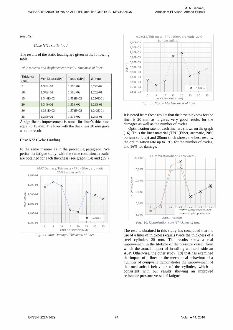
Case N°2 Cyclic Loading
In the same manner as in the preceding paragraph. We
perform a fatigue study, with the same conditions, results
are obtained for each thickness (see graph (14) and (15))
Fig. 14. Max Damage/ Thickness of liner
Fig. 15. Ncycle life/Thickness of liner
It is noted from these results that the best thickness for the
liner is 20 mm as it gives very good results for the
damages as well as the number of cycles.
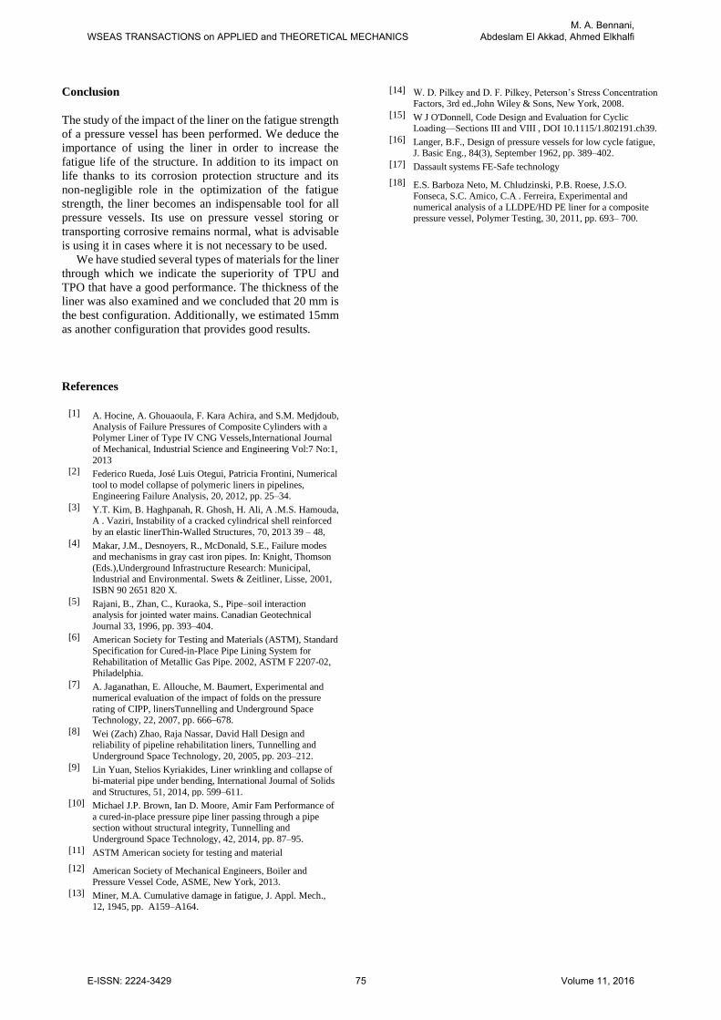
Optimization rate for each liner are shown on the graph
(16). Thus the liner material (TPU (Ether, aromatic, 20%
barium sulfate)) and 20mm thick shows the best results,
the optimization rate up to 19% for the number of cycles,
and 16% for damage.
Fig. 16. Optimisation rate /Thickness of liner
The results obtained in this study has concluded that the
use of a liner of thickness equals twice the thickness of a
steel cylinder, 20 mm. The results show a real
improvement in the lifetime of the pressure vessel, from
which the actual impact of installing a liner inside an
ASP. Otherwise, the other study [18] that has examined
the impact of a liner on the mechanical behaviour of a
cylinder of composite demonstrates the improvement of
the mechanical behaviour of the cylinder, which is
consistent with our results showing an improved
resistance pressure vessel of fatigue.
1,30E-04
1,40E-04
1,50E-04
1,60E-04
1,70E-04
1,80E-04
0 5 10 15 20 25 30 35
MA
X D
AM
AG
E
LINER'S THICKNESS(MM)
MAX Damage/Thickness - TPU (Ether, aromatic, 20% barium sulfate
Damage
5,50E+03
5,70E+03
5,90E+03
6,10E+03
6,30E+03
6,50E+03
6,70E+03
6,90E+03
7,10E+03
7,30E+03
7,50E+03
0 5 10 15 20 25 30 35
CYC
LE N
LINER'S THICKNESS (MM)
N,CYCLE/Thickness - TPU (Ether, aromatic, 20% barium sulfate)
N,CYCLE
-5,00%
0,00%
5,00%
10,00%
15,00%
20,00%
5 10 15 20 25 30 35
% O
PTI
MIZ
ATI
ON
LINER'S THICKNESS
% Optmization/liner's thickness
damage optomization
Ncycle optimization
WSEAS TRANSACTIONS on APPLIED and THEORETICAL MECHANICSM. A. Bennani,
Abdeslam El Akkad, Ahmed Elkhalfi
E-ISSN: 2224-3429 74 Volume 11, 2016
Conclusion
The study of the impact of the liner on the fatigue strength
of a pressure vessel has been performed. We deduce the
importance of using the liner in order to increase the
fatigue life of the structure. In addition to its impact on
life thanks to its corrosion protection structure and its
non-negligible role in the optimization of the fatigue
strength, the liner becomes an indispensable tool for all
pressure vessels. Its use on pressure vessel storing or
transporting corrosive remains normal, what is advisable
is using it in cases where it is not necessary to be used.
We have studied several types of materials for the liner
through which we indicate the superiority of TPU and
TPO that have a good performance. The thickness of the
liner was also examined and we concluded that 20 mm is
the best configuration. Additionally, we estimated 15mm
as another configuration that provides good results.
References
[1] A. Hocine, A. Ghouaoula, F. Kara Achira, and S.M. Medjdoub, Analysis of Failure Pressures of Composite Cylinders with a Polymer Liner of Type IV CNG Vessels,International Journal
of Mechanical, Industrial Science and Engineering Vol:7 No:1,
2013 [2] Federico Rueda, José Luis Otegui, Patricia Frontini, Numerical
tool to model collapse of polymeric liners in pipelines, Engineering Failure Analysis, 20, 2012, pp. 25–34.
[3] Y.T. Kim, B. Haghpanah, R. Ghosh, H. Ali, A .M.S. Hamouda,
A . Vaziri, Instability of a cracked cylindrical shell reinforced
by an elastic linerThin-Walled Structures, 70, 2013 39 – 48,
[4] Makar, J.M., Desnoyers, R., McDonald, S.E., Failure modes and mechanisms in gray cast iron pipes. In: Knight, Thomson
(Eds.),Underground Infrastructure Research: Municipal, Industrial and Environmental. Swets & Zeitliner, Lisse, 2001,
ISBN 90 2651 820 X.
[5] Rajani, B., Zhan, C., Kuraoka, S., Pipe–soil interaction analysis for jointed water mains. Canadian Geotechnical
Journal 33, 1996, pp. 393–404. [6] American Society for Testing and Materials (ASTM), Standard
Specification for Cured-in-Place Pipe Lining System for Rehabilitation of Metallic Gas Pipe. 2002, ASTM F 2207-02,
Philadelphia.
[7] A. Jaganathan, E. Allouche, M. Baumert, Experimental and numerical evaluation of the impact of folds on the pressure
rating of CIPP, linersTunnelling and Underground Space Technology, 22, 2007, pp. 666–678.
[8] Wei (Zach) Zhao, Raja Nassar, David Hall Design and reliability of pipeline rehabilitation liners, Tunnelling and
Underground Space Technology, 20, 2005, pp. 203–212.
[9] Lin Yuan, Stelios Kyriakides, Liner wrinkling and collapse of bi-material pipe under bending, International Journal of Solids
and Structures, 51, 2014, pp. 599–611. [10] Michael J.P. Brown, Ian D. Moore, Amir Fam Performance of
a cured-in-place pressure pipe liner passing through a pipe section without structural integrity, Tunnelling and
Underground Space Technology, 42, 2014, pp. 87–95.
[11] ASTM American society for testing and material
[12] American Society of Mechanical Engineers, Boiler and Pressure Vessel Code, ASME, New York, 2013.
[13] Miner, M.A. Cumulative damage in fatigue, J. Appl. Mech., 12, 1945, pp. A159–A164.
[14] W. D. Pilkey and D. F. Pilkey, Peterson’s Stress Concentration
Factors, 3rd ed.,John Wiley & Sons, New York, 2008.
[15] W J O'Donnell, Code Design and Evaluation for Cyclic Loading—Sections III and VIII , DOI 10.1115/1.802191.ch39.
[16] Langer, B.F., Design of pressure vessels for low cycle fatigue, J. Basic Eng., 84(3), September 1962, pp. 389–402.
[17] Dassault systems FE-Safe technology
[18] E.S. Barboza Neto, M. Chludzinski, P.B. Roese, J.S.O. Fonseca, S.C. Amico, C.A . Ferreira, Experimental and
numerical analysis of a LLDPE/HD PE liner for a composite pressure vessel, Polymer Testing, 30, 2011, pp. 693– 700.
WSEAS TRANSACTIONS on APPLIED and THEORETICAL MECHANICSM. A. Bennani,
Abdeslam El Akkad, Ahmed Elkhalfi
E-ISSN: 2224-3429 75 Volume 11, 2016