Embed Size (px)
Citation preview
Innovative Technologies for Romanian Anti-hail System
LAURENŢIU ALBOTEANU, CONSTANTIN ŞULEA, GHEORGHE MANOLEA
Faculty of Engineering in Electromechanics, Environment and Industrial Informatics
University of Craiova 107, Decebal Bl., 200440, Craiova, Tel.0251 435 724, Fax. 0251 435 255
ROMANIA [email protected]; [email protected]; [email protected]
Abstract: - About 60% storms on the Romanian territory (during the march-September period of one year) are
accompanied by hail falls and 40% of these hail falls lead to significant or even total losses of crops. So, this is a new and actual research domain that the present work is related to and its main goal consists in building up a
study concerning the existing technical solutions and exploring some new ways in order to solve the identified
problems.
The paper outlines the concerns of the research team at the University of Craiova, Innovation and Technology
Transfer Centre - CITT on combating hail. Mainly, the researches concern the equipments and the innovative
technologies for Romanian anti-hail systems.
Key-Words: - anti-hail, microcontroller, photovoltaic system, informatic system, monitoring information,
environment.
List of symbols and abbreviations ARL – automatic rocket launcher
ACPL – automatic center point launcher
B1, B2 – batteries
D1, D2- semiconductor diodes
ESRA - European Solar Radiation Atlas
EV- East West
Ga – solar irradiation
GIS – geographic information system GSM – global system for mobile communications
K1, K2, K3 – electric contacts
L1..L7 – static contactors
PC – personal computer PI1, PI2 – threshold values of current
PU1, PU2, PU3 - threshold values of voltage
PV- photovoltaic
RT1- radio telephone
SN- SouthNorth
SPI- serial port interface
Ta- ambient temperature
TC1, TC2- current transducers
TU- voltage transducer
1 Introduction A national anti-hail system was established in
our country in 1999, [24] and recently was
established a National Authority against hail fall and
for the stimulation of the rainfall. During the
mentioned period were developed a lot of research
activities supported by the government bodies or by
businesses. Presently there are concerns for the
extension of these activities through doctoral
researches, through international, cross-border or
regional partnerships researches. It can be said that
the management of hail fall and the rainfall
stimulation has become, in our country, a current
preoccupation.
The achievement of an anti-hail system in
Romania provides several advantages:
- the reduction of the losses produced by hail in
agriculture, but also in economic and domestic
areas;
- the creation of the premises for a rainfall (a ton of
water obtained from an artificial rainfall is 3-4 times
cheaper than the one obtained from the irrigation
water);
- the regional integration of the national Romanian
anti-hail system with similar systems from Ukraine,
Moldova, Bulgaria or Hungary;
The University of Craiova, Innovation and
Technology Transfer Center - CITT started the
research regarding the powering of local points anti-
hail missile launch from photovoltaic panels in
2000. The research was initiated with the Technical
University of Moldova in Chisinau, since in Republic of Moldova the energy security is a very
important problem. This research has been pursued
on the request of the constructor of the electrical and
mechanical part of the launch ramps for the anti-hail
missiles - Electromechanics Ploiesti - to monitor
WSEAS TRANSACTIONS on POWER SYSTEMS Laurentiu Alboteanu, Constantin Sulea, Gheorghe Manolea
ISSN: 1790-5060 297 Issue 4, Volume 5, October 2010
further information, submitted by local weather
radar to local launch points of anti-hail missiles.
A complex team was involved in the work,
consisting of professors, researchers and PhD
students.
2 Main researches objectives related
to suppression system The climate changes in the last decades led to
intensification of the hail falling processes, and also
to the alternation in long periods of drought. In this
context, several countries in the world practice
simple solutions or have developed complex anti-
hail systems to increase efficiency of action against
hail fall. Anti-hail systems are used in 29 countries
and several projects are ongoing.
The researches which take place in the world
presently have the following objectives:
- the improvement of technological actions by
studying micro and macro physical processes of
formation and evolution of cloudy and condensation
systems; - the reduction of the response time by
automating intervention systems (detection,
determination of parameters of seeding, launching
and monitoring of physical efficiency);
- the improvement of the monitoring criteria of
physical and economic efficiency actions, the
increasing of dispersion elements of active agents
efficiency (by shortening the nucleation time and by
the increase of the activities);
- the identification of new areas of systems’
application, taking into account the progresses
realized in influencing the weather phenomena.
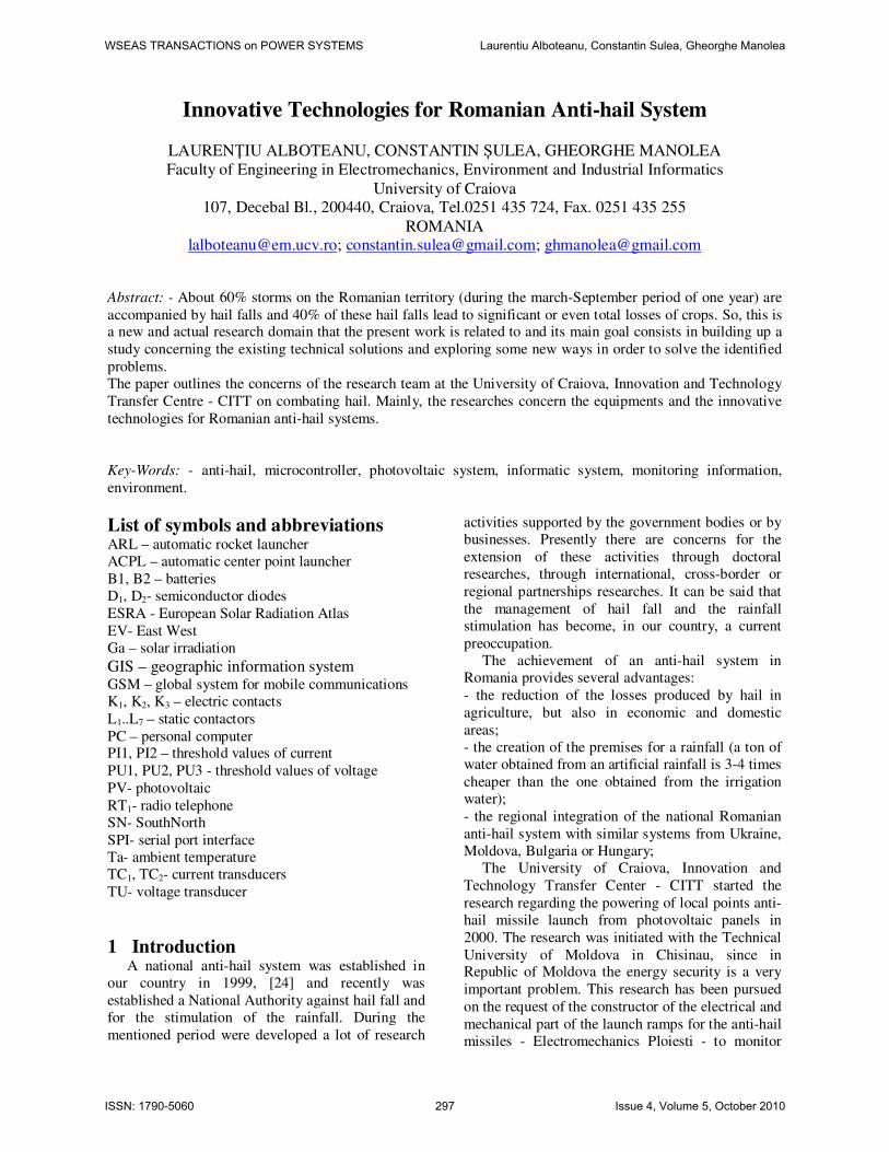
The anti-hail informatic system is a assembly
of hardware, software components, procedures,
strategies, activities and people united and
organized to process data related to combating
hail, to fulfill the task of reducing / eliminating
the damage caused by hail and the and
achievement of through measurable
performance criteria established (Fig.1).
In figure 1 is shown, generally, computer system architecture for monitoring anti-hail
units launch points. The hardware structure of the anti-hail computer
system comprises the following subsystems:
- equipments for identifying the potential carriers of
hail clouds;
- equipments for the coordination of the anti-hail
rockets launching;
- automated equipment for launching anti-hail
rockets;
- equipments for supplying electricity from solar
panels.
Fig. 1 Anti-hail informatic system
The informatic system integrates data related to:
the weather data, the coordinates of protected crops,
the coordinates of the launch points and central
points, types of crops, range of release points,
access roads, the presence of a missile launch point
on the ramp, data about the positioning of the launch
ramp, the selection methods, data on electricity
supply system, record launches, missile stocks, etc.
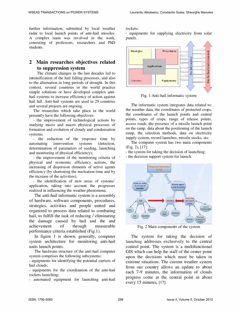
The computer system has two main components
(Fig. 2), [17]:
- the system for taking the decision of launching;
- - the decision support system for launch.
Fig. 2 Main components of the system
The system for taking the decision of launching addresses exclusively to the central
control point. The system is a multifunctional GIS which can help the staff of the center point
upon the decisions which must be taken in extreme situations. The current weather system
from our country allows an update to about each 7-9 minutes, the information of clouds
progress come at the central point in about
every 15 minutes, [17].
WSEAS TRANSACTIONS on POWER SYSTEMS Laurentiu Alboteanu, Constantin Sulea, Gheorghe Manolea
ISSN: 1790-5060 298 Issue 4, Volume 5, October 2010
3 Results researches regarding the
anti-hail system from Romania The researches made at the University of
Craiova CITT are concerned with the realization of
equipments for supplying power from photovoltaic
panels of specific equipment in a anti hail station,
monitoring of the information transmitted from the
meteorological station at the local point and the
automatic positioning of the rackets launch ramp
and an integrated system to receive and process a
large set of information [2], [3], [4], [5], [6], [7],
[13], [23].
This paper will present the results for the power
supply and for the coordination of the anti-hail
rockets launch ramp.
3.1 Equipment for the coordination of the
anti hail rockets launch The equipment contains:
- Automatic Rocket Launcher - ARL;
- Automatic Center Point Launcher-ACPL
connected as shown in figure 3.
Fig.3 Structure of the system for monitoring
information transmitted
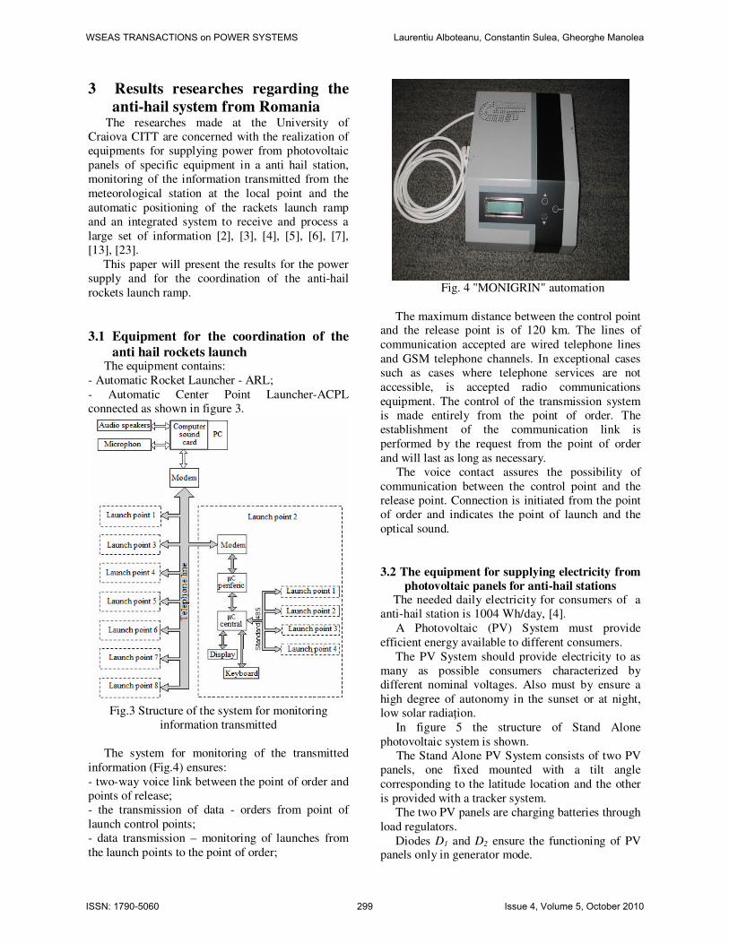
The system for monitoring of the transmitted
information (Fig.4) ensures:
- two-way voice link between the point of order and
points of release;
- the transmission of data - orders from point of
launch control points;
- data transmission – monitoring of launches from
the launch points to the point of order;
Fig. 4 "MONIGRIN" automation
The maximum distance between the control point and the release point is of 120 km. The lines of
communication accepted are wired telephone lines
and GSM telephone channels. In exceptional cases
such as cases where telephone services are not
accessible, is accepted radio communications
equipment. The control of the transmission system
is made entirely from the point of order. The
establishment of the communication link is
performed by the request from the point of order
and will last as long as necessary.
The voice contact assures the possibility of
communication between the control point and the
release point. Connection is initiated from the point
of order and indicates the point of launch and the
optical sound.
3.2 The equipment for supplying electricity from
photovoltaic panels for anti-hail stations The needed daily electricity for consumers of a
anti-hail station is 1004 Wh/day, [4].
A Photovoltaic (PV) System must provide
efficient energy available to different consumers.
The PV System should provide electricity to as
many as possible consumers characterized by
different nominal voltages. Also must by ensure a
high degree of autonomy in the sunset or at night,
low solar radiațion.
In figure 5 the structure of Stand Alone
photovoltaic system is shown.
The Stand Alone PV System consists of two PV
panels, one fixed mounted with a tilt angle
corresponding to the latitude location and the other
is provided with a tracker system.
The two PV panels are charging batteries through
load regulators.
Diodes D1 and D2 ensure the functioning of PV panels only in generator mode.
WSEAS TRANSACTIONS on POWER SYSTEMS Laurentiu Alboteanu, Constantin Sulea, Gheorghe Manolea
ISSN: 1790-5060 299 Issue 4, Volume 5, October 2010
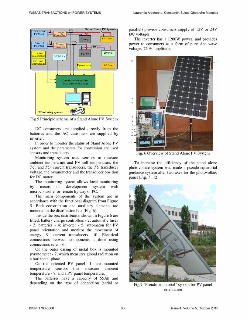
Fig.5 Principle scheme of a Stand Alone PV System
DC consumers are supplied directly from the
batteries and the AC customers are supplied by
inverter.
In order to monitor the status of Stand Alone PV
system and the parameters for conversion are used
sensors and transducers.
Monitoring system uses sensors to measure
ambient temperature and PV cell temperature, the TC1 and TC2 current transducers, the TU transducer
voltage, the pyranometer and the transducer position
for DC motor.
The monitoring system allows local monitoring
by means of development system with
microcontroller or remote by way of PC.
The main components of the system are in
accordance with the functional diagram from Figure
5. Both construction and auxiliary elements are
mounted in the distribution box (Fig. 6).
Inside the box distribution shown in Figure 6 are
fitted: battery charge controllers - 2; automatic fuses
- 3; batteries - 4; inverter - 5, automaton for PV
panel orientation and monitor the movement of
energy -9; current transducers -10. Electrical
connections between components is done using
connections ruler - 6.
On the outer casing of metal box is mounted
pyranometer - 7, which measures global radiation on
a horizontal plane.
On the oriented PV panel -1, are mounted
temperature sensors that measure ambient
temperature - 8, and a PV panel temperature.
The batteries have a capacity of 55Ah and depending on the type of connection (serial or
parallel) provide consumers supply of 12V or 24V
DC voltages.
The inverter has a 1200W power, and provides
power to consumers as a form of pure sine wave
voltage, 220V amplitude.
Fig. 6 Overview of Stand Alone PV System
To increase the efficiency of the stand alone
photovoltaic system was made a pseudo-equatorial
guidance system after two axes for the photovoltaic
panel (Fig. 7), [2] .
Fig.7 "Pseudo-equatorial" system for PV panel
orientation
WSEAS TRANSACTIONS on POWER SYSTEMS Laurentiu Alboteanu, Constantin Sulea, Gheorghe Manolea
ISSN: 1790-5060 300 Issue 4, Volume 5, October 2010
The PV panel follows diurnal motion of the Sun
in the direction of EV, and can be adjusted daily the
angle of SN direction of the photovoltaic panel, so
that the stand alone photovoltaic system to provide a
maximum amount of energy.
Among the existing orientation systems in the
literature [9], [14], the most suitable solution
proposed for orientation of the PV panel, is pseudo-
equatorial orientation system, because this system
does not require a simultaneous combination of
movements for the two axes.
3.2.1 The modeling and the simulation of equipment for power supply from
photovoltaic panels In order to validate the corresponding
mathematical models of the solar energy conversion
system the modeling and the simulation was done in
Matlab Simulink [26]. With the aid of Homer
programme it was simulated the process of
production-consumption of energy for the proposed
photovoltaic system.
For practical use, Simulink block models for
each component of an autonomous PV system are
grouped into blocks “Subsystem”. Subsystem blocks
contain block models for PV generator, battery, inverter, charge.
Simulink model of the entire Stand Alone PV
System is shown in figure 8.
The total system has thus as inputs the irradiation
and the ambient temperature. These are used in the
PV module together with the voltage from the
controller to generate the PV current.
The basic blocks of the library can be used to
build more specific structures, [1].
Fig. 8 Simulink model of the Stand Alone PV
System
Another powerful feature of the Simulink, called
masking, is that it can simplify the use of the model
by replacing many dialog boxes in a subsystem with
a single dialog box. Instead of requiring the user of
the model to open each block and enter parameter
values, those parameter values can be entered on the
mask dialog block and passed to the blocks in the
masked subsystem.
The most relevant parts of the series with
particular events, from each of the set data of inputs,
are chosen and analysed for understanding and
modelling of the Stand-Alone PV system, [11], [15].
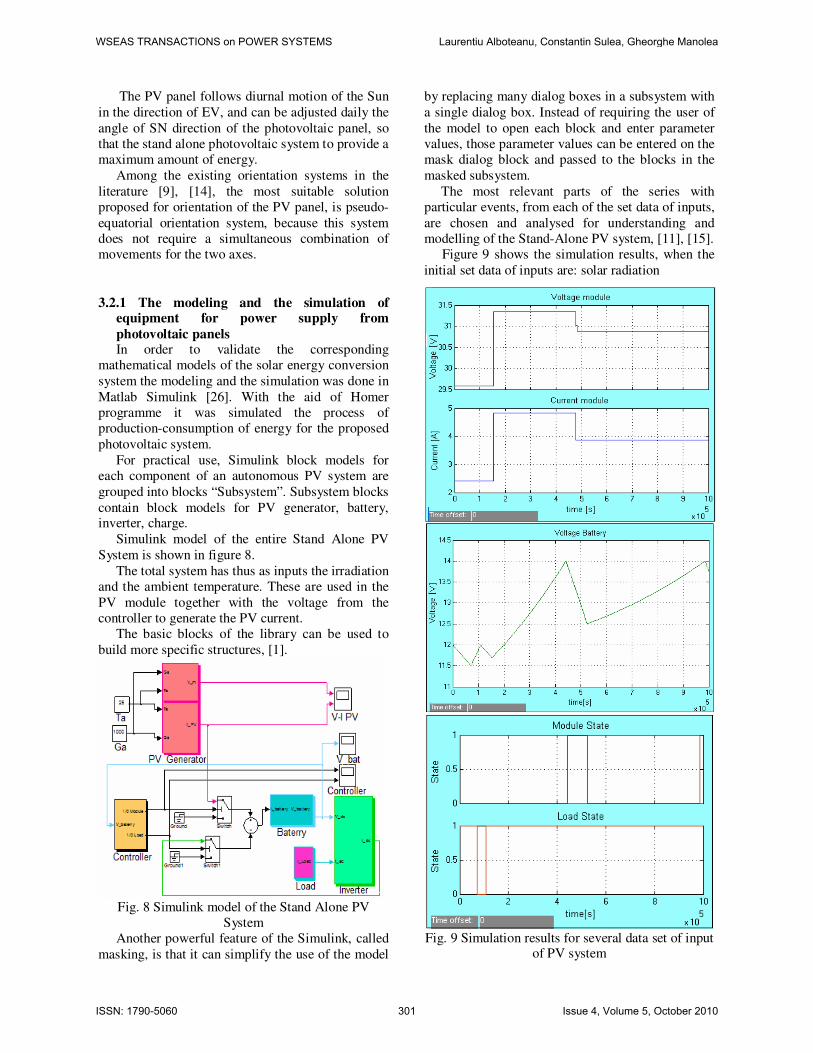
Figure 9 shows the simulation results, when the
initial set data of inputs are: solar radiation
Fig. 9 Simulation results for several data set of input
of PV system
WSEAS TRANSACTIONS on POWER SYSTEMS Laurentiu Alboteanu, Constantin Sulea, Gheorghe Manolea
ISSN: 1790-5060 301 Issue 4, Volume 5, October 2010
ambient temperature Ta=15oC, the load is connected
and the PV current is directly used in the charging
of the battery, but the IPV<ILoad and the battery
voltage decreasing until Vmin_off=11.5V. In this time,
the load is disconnected, and the battery voltage
increasing until Vmin_on=12V, when the load is
reconnected on the Stand-Alone PV system.
In the moment when the set data of inputs are
modified: solar radiation Ga=1000W/m2, ambient
temperature Ta=25oC, the battery is charging. In the
moment when battery voltage reaches the limit of
the charging voltage Vmax_off =14V, the PV generator
is disconnected by the PV controller of the Stand-
Alone PV system, in order to avoid overcharging.
The battery is discharging because the load is
connected on the system.
When battery voltage reaches the limit
Vmax_on=12.5V, the PV generator is reconnected on
the Stand-Alone PV system.
At a solar radiation Ga=800W/m2 and an
ambient temperature Ta=20oC, the battery voltage
increasing, because IPV>ILoad.
The whole Stand-Alone PV system has the solar
radiation as input variables, the ambient
temperature; these parameters are directly involved
in converting solar energy.
In order to determine the energy production and
the energy efficiency of Stand Alone PV System, it
was developed the modeling and the simulation of
this system, [18]. It was used a specialized
software for simulation of renewable sources
named HOMER [27].
HOMER simulates the operation of a system by
making energy balance calculations for each of the
8,760 hours in a year. For each hour, HOMER
compares the electric demand in the hour to the
energy that the system can supply in that hour, and
calculates the flows of energy to and from each
component of the system. For this system that
includes batteries, HOMER also decides for each
hour how to operate the generators and whether to
charge or discharge the batteries.
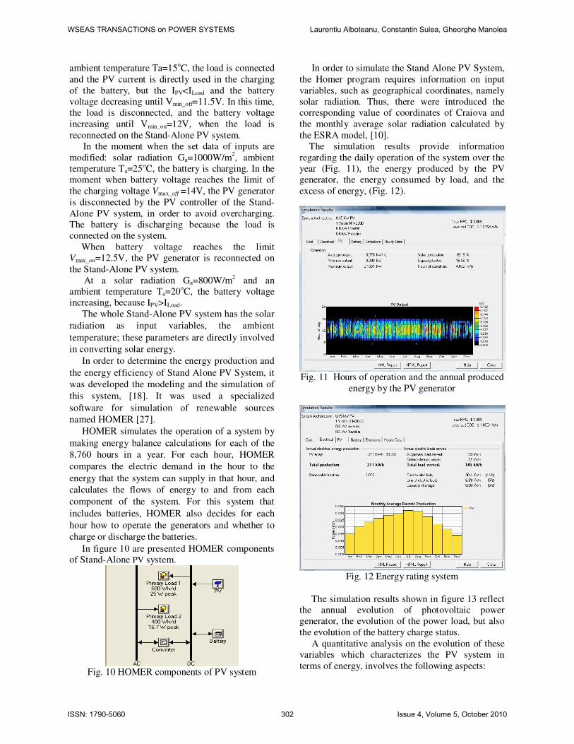
In figure 10 are presented HOMER components
of Stand-Alone PV system.
Fig. 10 HOMER components of PV system
In order to simulate the Stand Alone PV System,
the Homer program requires information on input
variables, such as geographical coordinates, namely
solar radiation. Thus, there were introduced the
corresponding value of coordinates of Craiova and
the monthly average solar radiation calculated by
the ESRA model, [10].
The simulation results provide information
regarding the daily operation of the system over the
year (Fig. 11), the energy produced by the PV
generator, the energy consumed by load, and the
excess of energy, (Fig. 12).
Fig. 11 Hours of operation and the annual produced
energy by the PV generator
Fig. 12 Energy rating system
The simulation results shown in figure 13 reflect
the annual evolution of photovoltaic power
generator, the evolution of the power load, but also
the evolution of the battery charge status.
A quantitative analysis on the evolution of these
variables which characterizes the PV system in
terms of energy, involves the following aspects:
WSEAS TRANSACTIONS on POWER SYSTEMS Laurentiu Alboteanu, Constantin Sulea, Gheorghe Manolea
ISSN: 1790-5060 302 Issue 4, Volume 5, October 2010
- the active power generator available PV power is
higher than that required consumers;
- the energy stored in battery deficit recorded during
January to March, respectively from October to
December period, during which the anti-hail stations
are in operation.
Fig.13 Evolution parameters of PV system for a
year
4.2.2 Modeling of the monitoring system for the movement of energy for ranked priorities
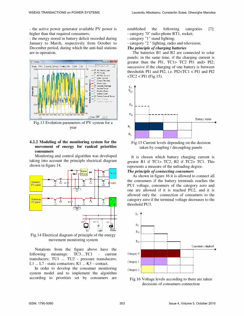
consumers Monitoring and control algorithm was developed
taking into account the principle electrical diagram
shown in figure 14.
Fig.14 Electrical diagram of principle of the energy
movement monitoring system
Notations from the figure above have the
following meanings: TC3…TC1 - current
transducers; TU1 ... TU2 - pressure transducers;
L1 ... L7 - static contactors; K1 ... K3 – contact.
In order to develop the consumer monitoring
system model and to implement the algorithm
according to priorities set by consumers are
established the following categories [7]:
- category "0" radio-phone RT1, rocket;
- category "1" stand lighting;
- category "2 " lighting, radio and television; The principle of charging batteries
The batteries B1 and B2 are connected to solar
panels: in the same time, if the charging current is
greater than the PI1, TC1> TC2 PI1 and> PI2;
successive if the charging of one battery is between
thresholds PI1 and PI2, i.e. PI2<TC1 < PI1 and PI2
<TC2 < PI1 (Fig.15).
Fig.15 Current levels depending on the decision
taken by coupling / decoupling panels
It is chosen which battery charging current is
greater B1 if TC1> TC2, B2 if TC2> TC1. This
represents a measure of the unloading degree.
The principle of connecting consumers As shown in figure 16 it is allowed to connect all
the consumers if the battery terminals reaches the
PU1 voltage, consumers of the category zero and
one are allowed if it is reached PU2, and it is
allowed only the connection of consumers to the
category zero if the terminal voltage decreases to the
threshold PU3.
Fig.16 Voltage levels according to there are taken
decisions of consumers connection
WSEAS TRANSACTIONS on POWER SYSTEMS Laurentiu Alboteanu, Constantin Sulea, Gheorghe Manolea
ISSN: 1790-5060 303 Issue 4, Volume 5, October 2010
3.2.3 Simulation of the monitoring system for
the movement of energy for consumers with
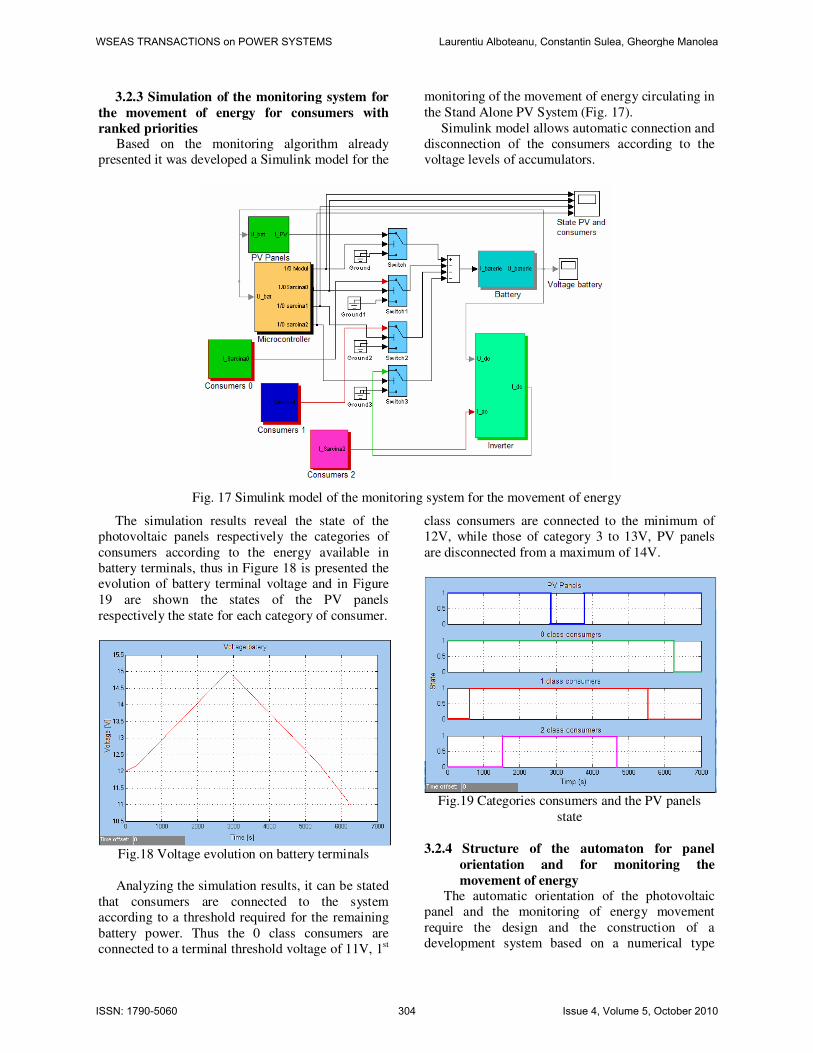
ranked priorities Based on the monitoring algorithm already
presented it was developed a Simulink model for the
monitoring of the movement of energy circulating in
the Stand Alone PV System (Fig. 17).
Simulink model allows automatic connection and
disconnection of the consumers according to the
voltage levels of accumulators.
Fig. 17 Simulink model of the monitoring system for the movement of energy
The simulation results reveal the state of the
photovoltaic panels respectively the categories of
consumers according to the energy available in
battery terminals, thus in Figure 18 is presented the
evolution of battery terminal voltage and in Figure
19 are shown the states of the PV panels
respectively the state for each category of consumer.
Fig.18 Voltage evolution on battery terminals
Analyzing the simulation results, it can be stated
that consumers are connected to the system
according to a threshold required for the remaining
battery power. Thus the 0 class consumers are
connected to a terminal threshold voltage of 11V, 1st
class consumers are connected to the minimum of
12V, while those of category 3 to 13V, PV panels
are disconnected from a maximum of 14V.
Fig.19 Categories consumers and the PV panels
state
3.2.4 Structure of the automaton for panel
orientation and for monitoring the
movement of energy The automatic orientation of the photovoltaic
panel and the monitoring of energy movement
require the design and the construction of a
development system based on a numerical type
WSEAS TRANSACTIONS on POWER SYSTEMS Laurentiu Alboteanu, Constantin Sulea, Gheorghe Manolea
ISSN: 1790-5060 304 Issue 4, Volume 5, October 2010
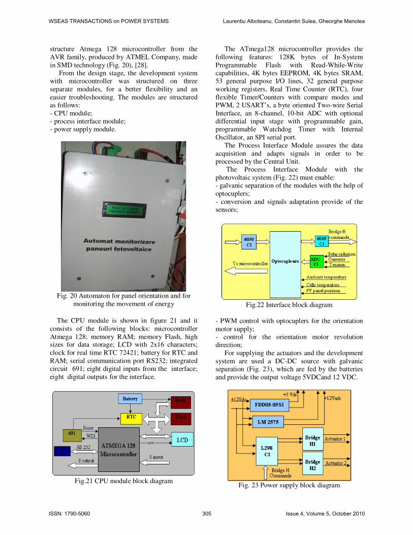
structure Atmega 128 microcontroller from the
AVR family, produced by ATMEL Company, made
in SMD technology (Fig. 20), [28].
From the design stage, the development system
with microcontroller was structured on three
separate modules, for a better flexibility and an
easier troubleshooting. The modules are structured
as follows:
- CPU module;
- process interface module;
- power supply module.
Fig. 20 Automaton for panel orientation and for
monitoring the movement of energy
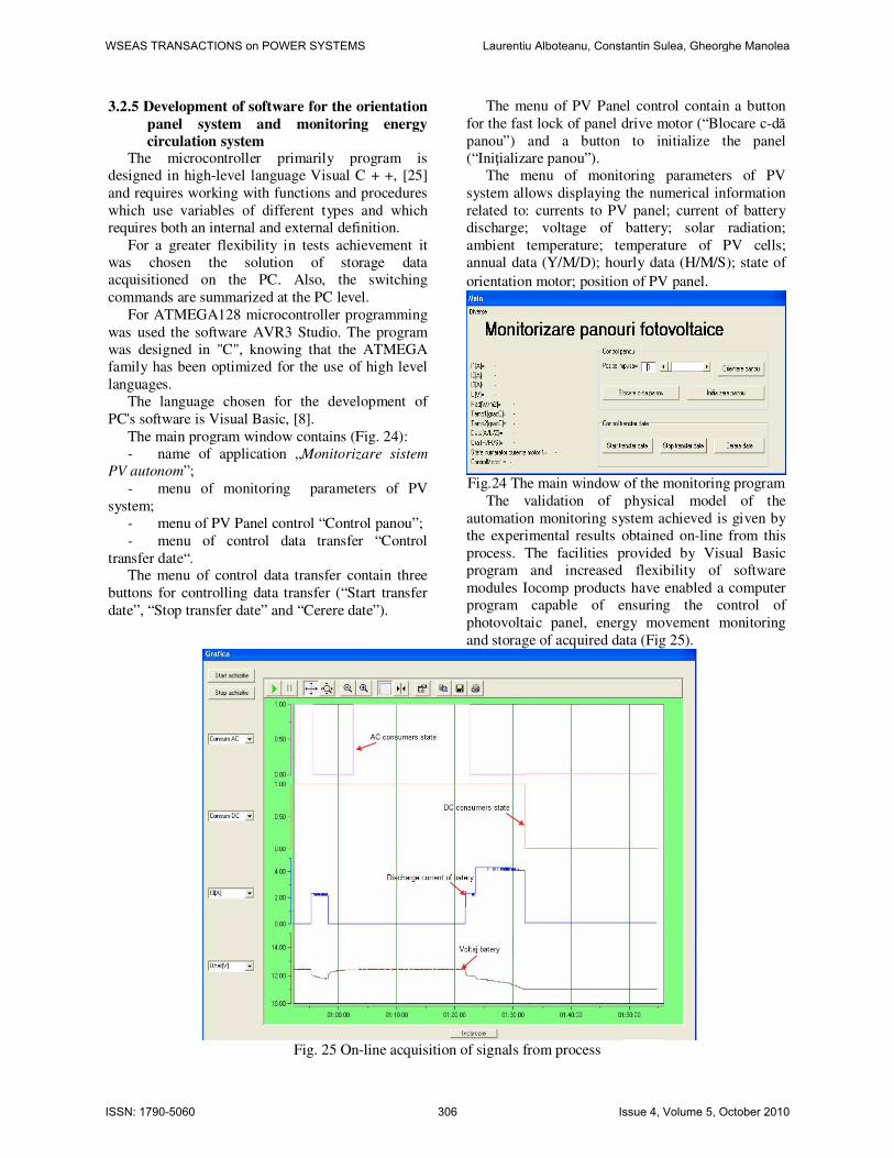
The CPU module is shown in figure 21 and it
consists of the following blocks: microcontroller
Atmega 128; memory RAM; memory Flash, high sizes for data storage; LCD with 2x16 characters;
clock for real time RTC 72421; battery for RTC and
RAM; serial communication port RS232; integrated
circuit 691; eight digital inputs from the interface;
eight digital outputs for the interface.
Fig.21 CPU module block diagram
The ATmega128 microcontroller provides the
following features: 128K bytes of In-System
Programmable Flash with Read-While-Write
capabilities, 4K bytes EEPROM, 4K bytes SRAM,
53 general purpose I/O lines, 32 general purpose
working registers, Real Time Counter (RTC), four
flexible Timer/Counters with compare modes and
PWM, 2 USART’s, a byte oriented Two-wire Serial
Interface, an 8-channel, 10-bit ADC with optional
differential input stage with programmable gain,
programmable Watchdog Timer with Internal
Oscillator, an SPI serial port.
The Process Interface Module assures the data
acquisition and adapts signals in order to be
processed by the Central Unit.
The Process Interface Module with the
photovoltaic system (Fig. 22) must enable:
- galvanic separation of the modules with the help of
optocuplers;
- conversion and signals adaptation provide of the
sensors;
Fig.22 Interface block diagram
- PWM control with optocuplers for the orientation
motor supply;
- control for the orientation motor revolution
direction;
For supplying the actuators and the development
system are used a DC-DC source with galvanic
separation (Fig. 23), which are fed by the batteries
and provide the output voltage 5VDCand 12 VDC.
Fig. 23 Power supply block diagram
WSEAS TRANSACTIONS on POWER SYSTEMS Laurentiu Alboteanu, Constantin Sulea, Gheorghe Manolea
ISSN: 1790-5060 305 Issue 4, Volume 5, October 2010
3.2.5 Development of software for the orientation
panel system and monitoring energy
circulation system The microcontroller primarily program is
designed in high-level language Visual C + +, [25]
and requires working with functions and procedures
which use variables of different types and which
requires both an internal and external definition.
For a greater flexibility in tests achievement it
was chosen the solution of storage data
acquisitioned on the PC. Also, the switching
commands are summarized at the PC level.
For ATMEGA128 microcontroller programming
was used the software AVR3 Studio. The program
was designed in "C", knowing that the ATMEGA
family has been optimized for the use of high level
languages.
The language chosen for the development of
PC's software is Visual Basic, [8].
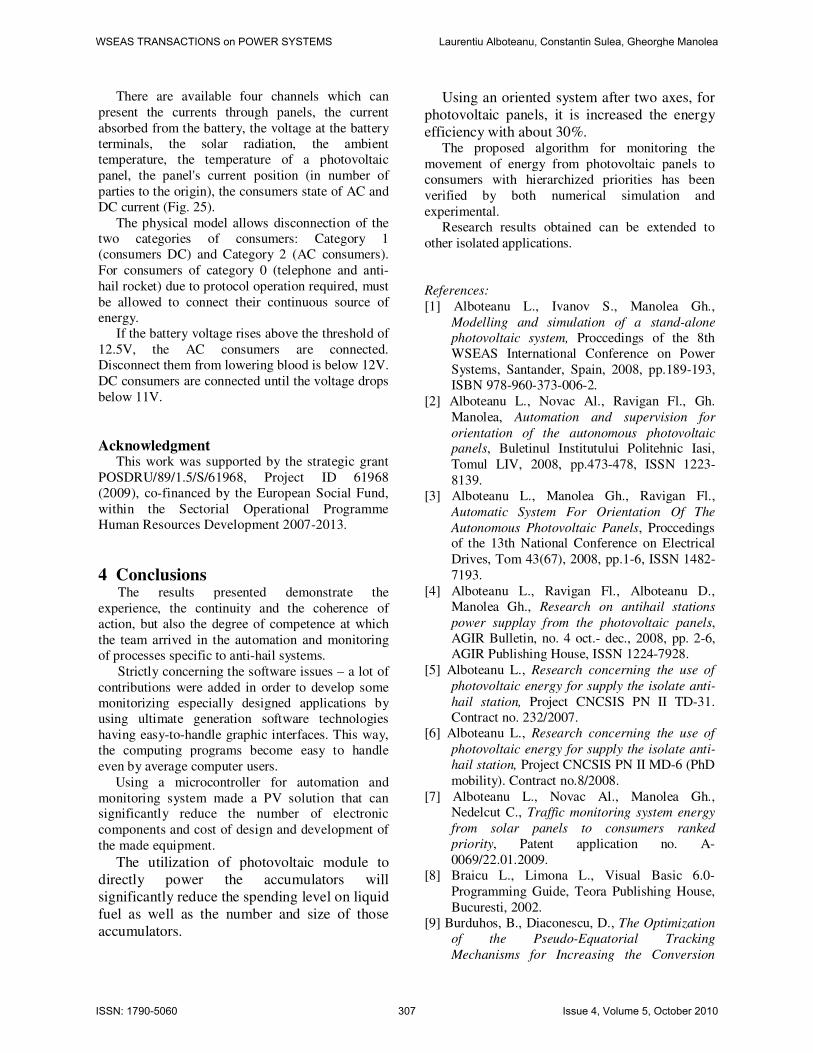
The main program window contains (Fig. 24):
- name of application „Monitorizare sistem
PV autonom”;
- menu of monitoring parameters of PV
system;
- menu of PV Panel control “Control panou”;
- menu of control data transfer “Control
transfer date“. The menu of control data transfer contain three
buttons for controlling data transfer (“Start transfer
date”, “Stop transfer date” and “Cerere date”).
The menu of PV Panel control contain a button
for the fast lock of panel drive motor (“Blocare c-dă
panou”) and a button to initialize the panel
(“Iniţializare panou”).
The menu of monitoring parameters of PV
system allows displaying the numerical information
related to: currents to PV panel; current of battery
discharge; voltage of battery; solar radiation;
ambient temperature; temperature of PV cells;
annual data (Y/M/D); hourly data (H/M/S); state of
orientation motor; position of PV panel.
Fig.24 The main window of the monitoring program
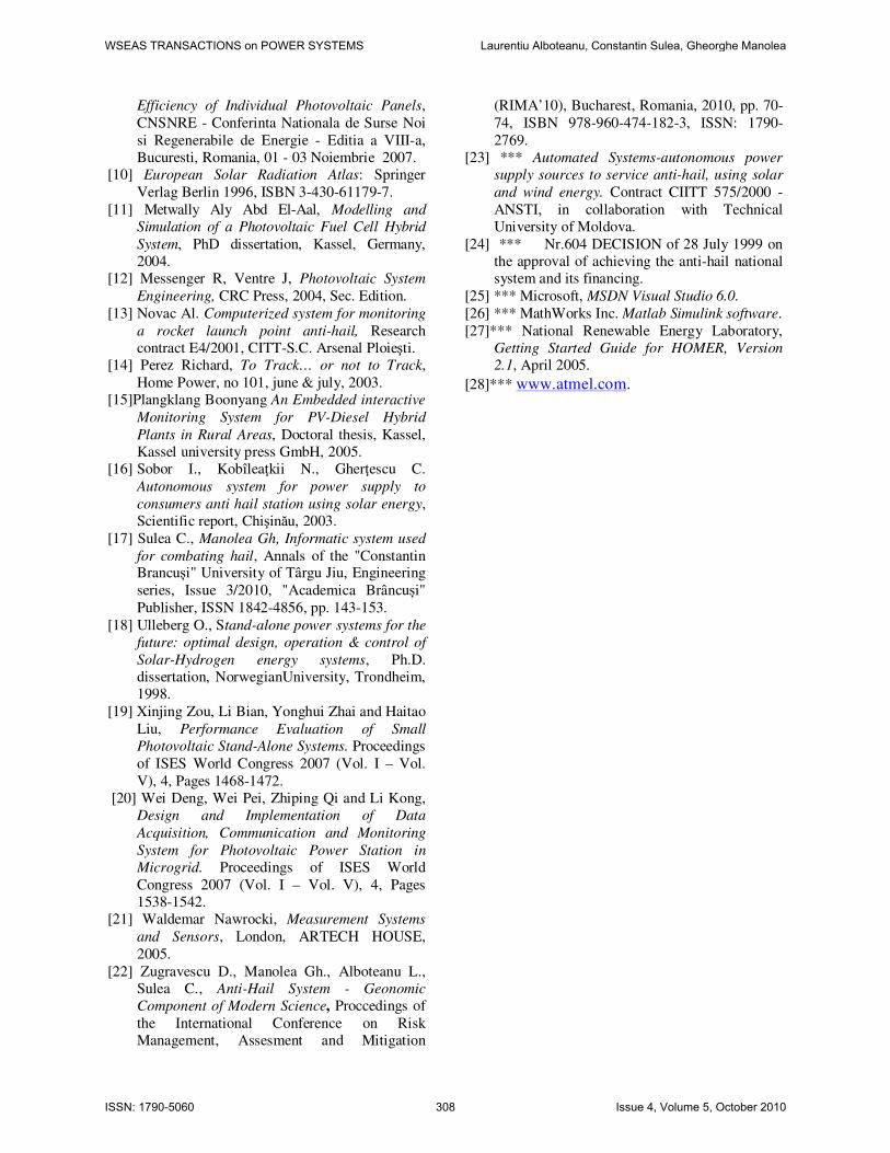
The validation of physical model of the
automation monitoring system achieved is given by
the experimental results obtained on-line from this
process. The facilities provided by Visual Basic
program and increased flexibility of software
modules Iocomp products have enabled a computer
program capable of ensuring the control of
photovoltaic panel, energy movement monitoring
and storage of acquired data (Fig 25).
Fig. 25 On-line acquisition of signals from process
WSEAS TRANSACTIONS on POWER SYSTEMS Laurentiu Alboteanu, Constantin Sulea, Gheorghe Manolea
ISSN: 1790-5060 306 Issue 4, Volume 5, October 2010
There are available four channels which can
present the currents through panels, the current
absorbed from the battery, the voltage at the battery
terminals, the solar radiation, the ambient
temperature, the temperature of a photovoltaic
panel, the panel's current position (in number of
parties to the origin), the consumers state of AC and
DC current (Fig. 25).
The physical model allows disconnection of the
two categories of consumers: Category 1
(consumers DC) and Category 2 (AC consumers).
For consumers of category 0 (telephone and anti-
hail rocket) due to protocol operation required, must
be allowed to connect their continuous source of
energy.
If the battery voltage rises above the threshold of
12.5V, the AC consumers are connected.
Disconnect them from lowering blood is below 12V.
DC consumers are connected until the voltage drops
below 11V.
Acknowledgment This work was supported by the strategic grant
POSDRU/89/1.5/S/61968, Project ID 61968
(2009), co-financed by the European Social Fund,
within the Sectorial Operational Programme
Human Resources Development 2007-2013.
4 Conclusions The results presented demonstrate the
experience, the continuity and the coherence of
action, but also the degree of competence at which
the team arrived in the automation and monitoring
of processes specific to anti-hail systems.
Strictly concerning the software issues – a lot of
contributions were added in order to develop some
monitorizing especially designed applications by
using ultimate generation software technologies
having easy-to-handle graphic interfaces. This way,
the computing programs become easy to handle
even by average computer users.
Using a microcontroller for automation and
monitoring system made a PV solution that can significantly reduce the number of electronic
components and cost of design and development of
the made equipment.
The utilization of photovoltaic module to
directly power the accumulators will
significantly reduce the spending level on liquid
fuel as well as the number and size of those
accumulators.
Using an oriented system after two axes, for
photovoltaic panels, it is increased the energy
efficiency with about 30%. The proposed algorithm for monitoring the
movement of energy from photovoltaic panels to
consumers with hierarchized priorities has been
verified by both numerical simulation and
experimental.
Research results obtained can be extended to
other isolated applications.
References:
[1] Alboteanu L., Ivanov S., Manolea Gh.,
Modelling and simulation of a stand-alone
photovoltaic system, Proccedings of the 8th
WSEAS International Conference on Power
Systems, Santander, Spain, 2008, pp.189-193,
ISBN 978-960-373-006-2.
[2] Alboteanu L., Novac Al., Ravigan Fl., Gh.
Manolea, Automation and supervision for
orientation of the autonomous photovoltaic panels, Buletinul Institutului Politehnic Iasi,
Tomul LIV, 2008, pp.473-478, ISSN 1223-
8139.
[3] Alboteanu L., Manolea Gh., Ravigan Fl.,
Automatic System For Orientation Of The
Autonomous Photovoltaic Panels, Proccedings of the 13th National Conference on Electrical
Drives, Tom 43(67), 2008, pp.1-6, ISSN 1482-
7193.
[4] Alboteanu L., Ravigan Fl., Alboteanu D.,
Manolea Gh., Research on antihail stations
power supplay from the photovoltaic panels,
AGIR Bulletin, no. 4 oct.- dec., 2008, pp. 2-6,
AGIR Publishing House, ISSN 1224-7928.
[5] Alboteanu L., Research concerning the use of
photovoltaic energy for supply the isolate anti-
hail station, Project CNCSIS PN II TD-31.
Contract no. 232/2007.
[6] Alboteanu L., Research concerning the use of
photovoltaic energy for supply the isolate anti-
hail station, Project CNCSIS PN II MD-6 (PhD
mobility). Contract no.8/2008.
[7] Alboteanu L., Novac Al., Manolea Gh.,
Nedelcut C., Traffic monitoring system energy
from solar panels to consumers ranked
priority, Patent application no. A-
0069/22.01.2009.
[8] Braicu L., Limona L., Visual Basic 6.0-
Programming Guide, Teora Publishing House,
Bucuresti, 2002.
[9] Burduhos, B., Diaconescu, D., The Optimization
of the Pseudo-Equatorial Tracking
Mechanisms for Increasing the Conversion
WSEAS TRANSACTIONS on POWER SYSTEMS Laurentiu Alboteanu, Constantin Sulea, Gheorghe Manolea
ISSN: 1790-5060 307 Issue 4, Volume 5, October 2010
Efficiency of Individual Photovoltaic Panels,
CNSNRE - Conferinta Nationala de Surse Noi
si Regenerabile de Energie - Editia a VIII-a,
Bucuresti, Romania, 01 - 03 Noiembrie 2007.
[10] European Solar Radiation Atlas: Springer
Verlag Berlin 1996, ISBN 3-430-61179-7.
[11] Metwally Aly Abd El-Aal, Modelling and
Simulation of a Photovoltaic Fuel Cell Hybrid
System, PhD dissertation, Kassel, Germany,
2004.
[12] Messenger R, Ventre J, Photovoltaic System
Engineering, CRC Press, 2004, Sec. Edition.
[13] Novac Al. Computerized system for monitoring
a rocket launch point anti-hail, Research
contract E4/2001, CITT-S.C. Arsenal Ploieşti.
[14] Perez Richard, To Track… or not to Track,
Home Power, no 101, june & july, 2003.
[15]Plangklang Boonyang An Embedded interactive
Monitoring System for PV-Diesel Hybrid
Plants in Rural Areas, Doctoral thesis, Kassel,
Kassel university press GmbH, 2005.
[16] Sobor I., Kobîleaţkii N., Gherţescu C.
Autonomous system for power supply to
consumers anti hail station using solar energy,
Scientific report, Chişinău, 2003.
[17] Sulea C., Manolea Gh, Informatic system used
for combating hail, Annals of the "Constantin Brancuși" University of Târgu Jiu, Engineering
series, Issue 3/2010, "Academica Brâncuși"
Publisher, ISSN 1842-4856, pp. 143-153.
[18] Ulleberg O., Stand-alone power systems for the
future: optimal design, operation & control of
Solar-Hydrogen energy systems, Ph.D.
dissertation, NorwegianUniversity, Trondheim,
1998.
[19] Xinjing Zou, Li Bian, Yonghui Zhai and Haitao
Liu, Performance Evaluation of Small
Photovoltaic Stand-Alone Systems. Proceedings
of ISES World Congress 2007 (Vol. I – Vol.
V), 4, Pages 1468-1472.
[20] Wei Deng, Wei Pei, Zhiping Qi and Li Kong,
Design and Implementation of Data
Acquisition, Communication and Monitoring
System for Photovoltaic Power Station in
Microgrid. Proceedings of ISES World
Congress 2007 (Vol. I – Vol. V), 4, Pages
1538-1542.
[21] Waldemar Nawrocki, Measurement Systems
and Sensors, London, ARTECH HOUSE,
2005.
[22] Zugravescu D., Manolea Gh., Alboteanu L.,
Sulea C., Anti-Hail System - Geonomic
Component of Modern Science, Proccedings of
the International Conference on Risk
Management, Assesment and Mitigation
(RIMA’10), Bucharest, Romania, 2010, pp. 70-
74, ISBN 978-960-474-182-3, ISSN: 1790-
2769.
[23] *** Automated Systems-autonomous power
supply sources to service anti-hail, using solar
and wind energy. Contract CIITT 575/2000 -
ANSTI, in collaboration with Technical
University of Moldova.
[24] *** Nr.604 DECISION of 28 July 1999 on
the approval of achieving the anti-hail national
system and its financing.
[25] *** Microsoft, MSDN Visual Studio 6.0.
[26] *** MathWorks Inc. Matlab Simulink software.
[27]*** National Renewable Energy Laboratory,
Getting Started Guide for HOMER, Version
2.1, April 2005.
[28]*** www.atmel.com.
WSEAS TRANSACTIONS on POWER SYSTEMS Laurentiu Alboteanu, Constantin Sulea, Gheorghe Manolea
ISSN: 1790-5060 308 Issue 4, Volume 5, October 2010