Embed Size (px)
Citation preview
®
LA
BE
L
Weatherproof Multi-turn ActuatorsServomoteurs Multi-tours Etanches
AT RANGE / GAMME AT
T E C H N I C A L D A T A / D O N N É E S T E C H N I Q U E S
New
TEC
01-
04
_E+
F_G
RP
_rev
02
4 rue d’Arsonval - CS 70091 - 95505 Gonesse CEDEX France - Tel. : +33 (0)1 34 07 71 00 - Fax : +33 (0)1 07 71 01 - [email protected] - www.bernardcontrols.com
1
TEC
01-
04
_E+
F_G
RP
_rev
02
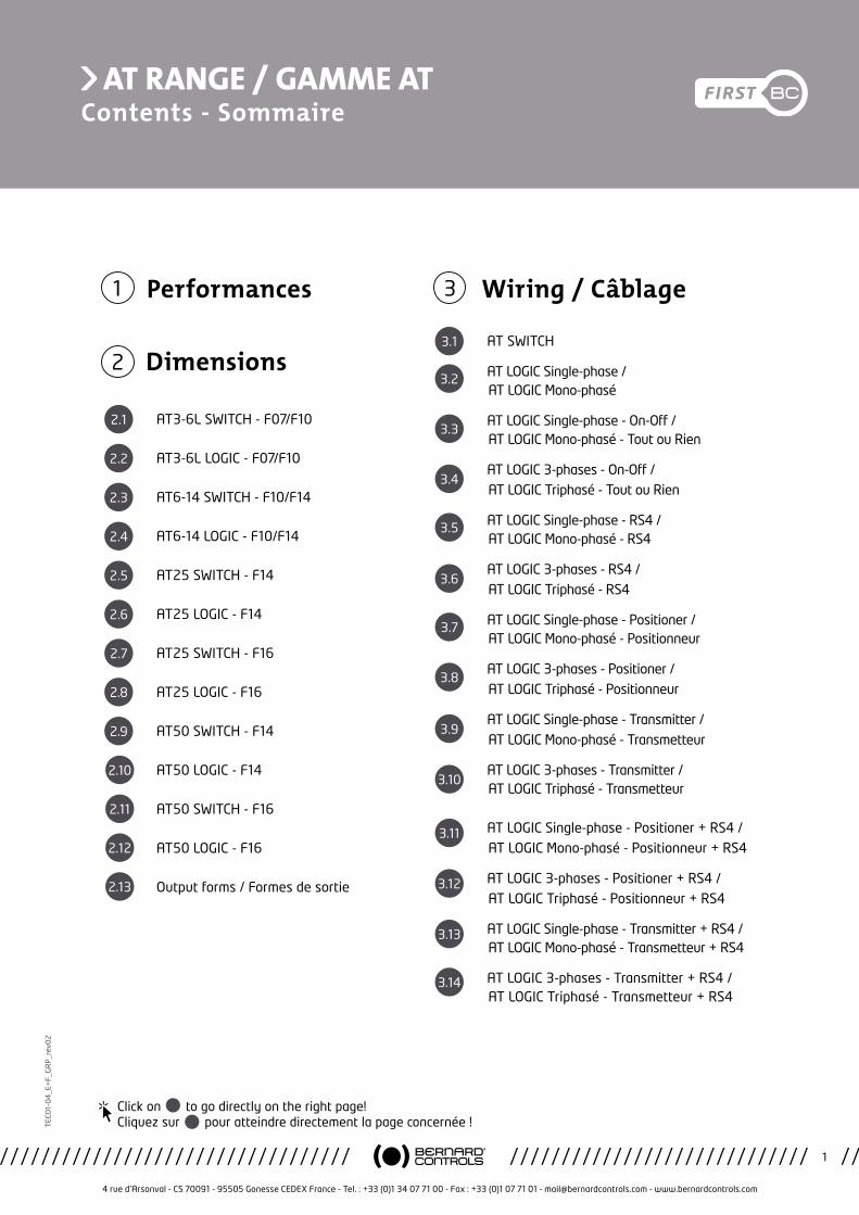
Wiring / Câblage3
3.1
AT SWITCH
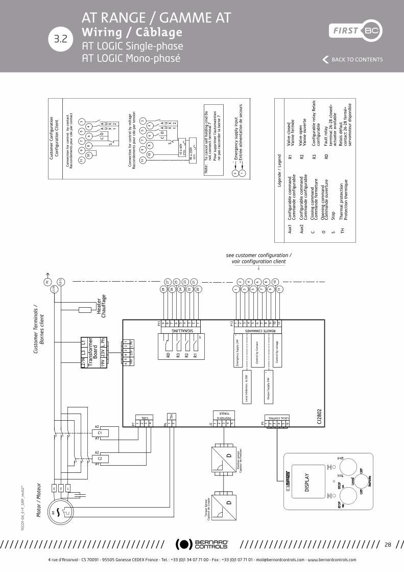
3.2 AT LOGIC Single-phase / AT LOGIC Mono-phasé
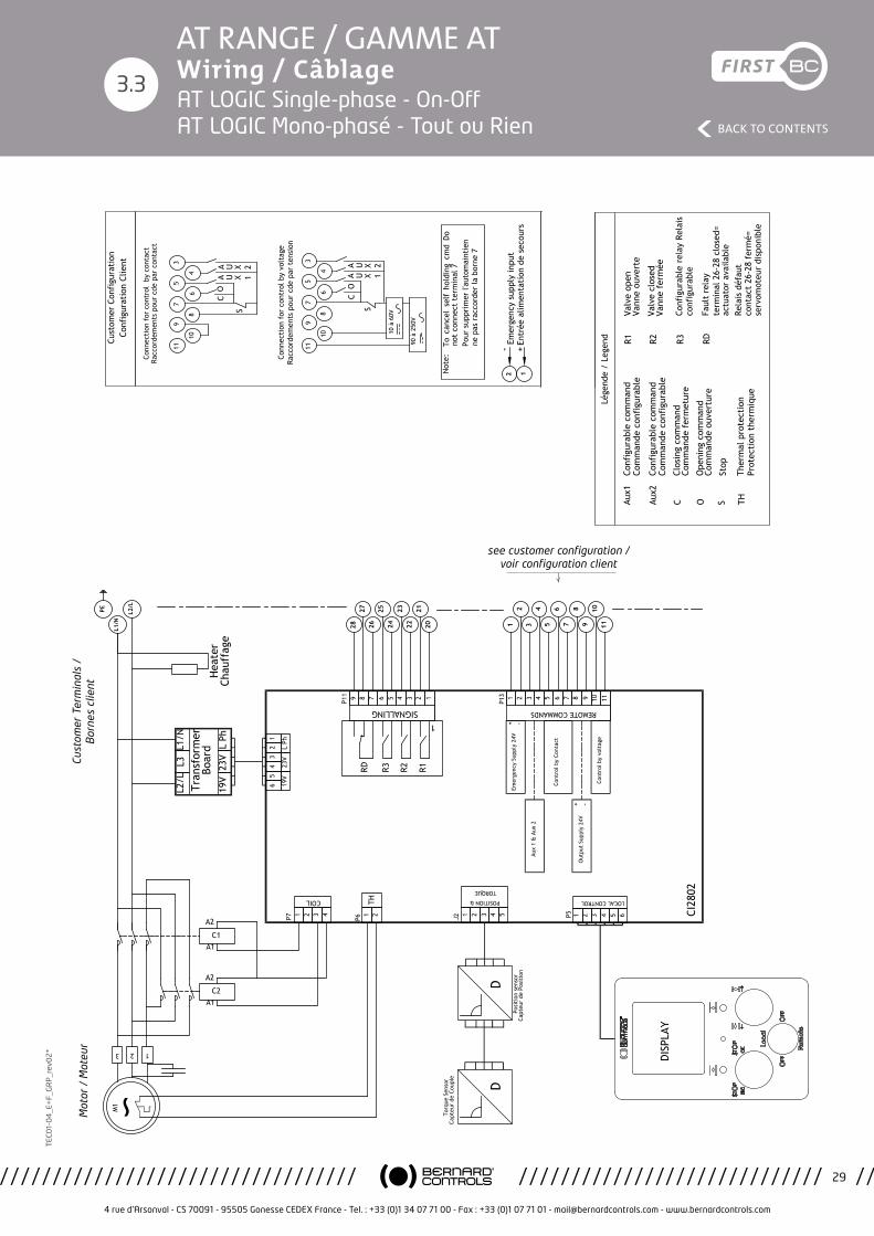
3.3 AT LOGIC Single-phase - On-Off /
AT LOGIC Mono-phasé - Tout ou Rien
3.4 AT LOGIC 3-phases - On-Off /
AT LOGIC Triphasé - Tout ou Rien
3.5 AT LOGIC Single-phase - RS4 / AT LOGIC Mono-phasé - RS4
3.6 AT LOGIC 3-phases - RS4 /
AT LOGIC Triphasé - RS4
3.7 AT LOGIC Single-phase - Positioner / AT LOGIC Mono-phasé - Positionneur
3.8 AT LOGIC 3-phases - Positioner /
AT LOGIC Triphasé - Positionneur
3.9 AT LOGIC Single-phase - Transmitter /
AT LOGIC Mono-phasé - Transmetteur
3.10 AT LOGIC 3-phases - Transmitter /
AT LOGIC Triphasé - Transmetteur
3.11 AT LOGIC Single-phase - Positioner + RS4 / AT LOGIC Mono-phasé - Positionneur + RS4
3.12 AT LOGIC 3-phases - Positioner + RS4 / AT LOGIC Triphasé - Positionneur + RS4
3.13 AT LOGIC Single-phase - Transmitter + RS4 / AT LOGIC Mono-phasé - Transmetteur + RS4
3.14 AT LOGIC 3-phases - Transmitter + RS4 / AT LOGIC Triphasé - Transmetteur + RS4
Dimensions2
2.1 AT3-6L SWITCH - F07/F10
2.2 AT3-6L LOGIC - F07/F10
2.3 AT6-14 SWITCH - F10/F14
2.4 AT6-14 LOGIC - F10/F14
2.5 AT25 SWITCH - F14
2.6 AT25 LOGIC - F14
2.7 AT25 SWITCH - F16
AT25 LOGIC - F16
AT50 SWITCH - F14
AT50 LOGIC - F14
AT50 SWITCH - F16
AT50 LOGIC - F16
Output forms / Formes de sortie
Performances1
Click on to go directly on the right page! Cliquez sur pour atteindre directement la page concernée !
AT RANGE / GAMME ATContents - Sommaire
2.8
2.9
2.10
2.11
2.12
2.13
AT RANGE / GAMME AT Performances
4 rue d’Arsonval - CS 70091 - 95505 Gonesse CEDEX France - Tel. : +33 (0)1 34 07 71 00 - Fax : +33 (0)1 07 71 01 - [email protected] - www.bernardcontrols.com
2
BACK TO CONTENTS
TEC
01-
04
_E+
F_G
RP
_rev
02
1
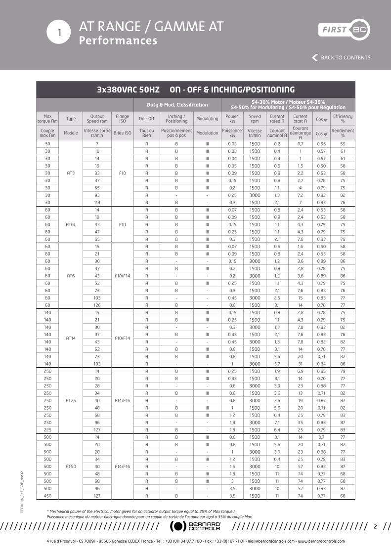
3x380VAC 50HZ ON - OFF & INCHING/POSITIONING
Duty & Mod, Classification S4-30% Motor / Moteur S4-30% S4-50% for Modulating / S4-50% pour Régulation
Max torque Nm Type Output
Speed rpmFlange
ISO On - Off Inching /Positioning Modulating Power*
kWSpeedrpm
Currentrated A
Currentstart A Cos j
Efficiency%
Couple max Nm Modèle Vitesse sortie
tr/min Bride ISO Tout ou Rien
Positionnement pas à pas Modulation Puissance*
kWVitesse tr/min
Courant nominal A
Courant démarrage
ACos j Rendement
%
30
AT3
7
F10
A B III 0,02 1500 0,2 0,7 0,55 59
30 10 A B III 0,03 1500 0,4 1 0,57 61
30 14 A B III 0,04 1500 0,4 1 0,57 61
30 19 A B III 0,05 1500 0,6 1,5 0,50 58
30 33 A B III 0,09 1500 0,8 2,2 0,53 58
30 47 A B III 0,15 1500 0,8 2,7 0,78 75
30 65 A B III 0,2 1500 1,1 4 0,79 75
30 93 A - - 0,25 3000 1,3 7,2 0,82 82
30 113 A B - 0,3 1500 2,1 7 0,83 76
60
AT6L
14
F10
A B III 0,07 1500 0,8 2,4 0,53 58
60 19 A B III 0,09 1500 0,8 2,4 0,53 58
60 33 A B III 0,15 1500 1,1 4,3 0,79 75
60 47 A B III 0,25 1500 1,1 4,3 0,79 75
60 65 A B III 0,3 1500 2,1 7,6 0,83 76
60
AT6
15
F10/F14
A B III 0,07 1500 0,6 1,6 0,50 58
60 21 A B III 0,09 1500 0,8 2,4 0,53 58
60 30 A - - 0,15 3000 1,2 3,6 0,89 86
60 37 A B III 0,2 1500 0,8 2,8 0,78 75
60 43 A - - 0,2 3000 1,2 3,6 0,89 86
60 52 A B III 0,25 1500 1,1 4,3 0,79 75
60 73 A B - 0,3 1500 2,1 7,6 0,83 76
60 103 A - - 0,45 3000 2,5 15 0,83 77
60 126 A B - 0,6 1500 3,1 14 0,70 77
140
AT14
15
F10/F14
A B III 0,15 1500 0,8 2,8 0,78 75
140 21 A B III 0,25 1500 1,1 4,3 0,79 75
140 30 A - - 0,3 3000 1,3 7,8 0,82 82
140 37 A B III 0,45 1500 2,1 7,6 0,83 76
140 43 A - - 0,45 3000 1,3 7,8 0,82 82
140 52 A B III 0,6 1500 3,1 14 0,70 77
140 73 A B III 0,8 1500 5,6 20 0,71 82
140 103 A - - 1 3000 5,7 31 0,84 86
250
AT25
14
F14/F16
A B III 0,25 1500 1,9 6,9 0,85 79
250 20 A B III 0,45 1500 3,1 14 0,70 77
250 28 A - - 0,6 3000 3,9 23 0,88 77
250 34 A B III 0,6 1500 3,6 13 0,71 82
250 40 A - - 0,8 3000 3,6 19 0,87 87
250 48 A B III 1 1500 5,6 20 0,71 82
250 68 A B III 1,2 1500 6,4 25 0,79 83
250 96 A - - 1,8 3000 7,1 35 0,85 87
225 127 A B - 1,8 1500 6,4 25 0,79 83
500
AT50
14
F14/F16
A B III 0,6 1500 3,1 14 0,7 77
500 20 A B III 0,8 1500 5,6 20 0,71 82
500 28 A - - 1 3000 3,9 23 0,88 77
500 34 A B III 1,2 1500 6,4 25 0,79 83
500 40 A - - 1,5 3000 10 57 0,83 87
500 48 A B III 1,8 1500 11 74 0,77 68
500 68 A B III 3 1500 11 74 0,77 68
500 96 A - - 3,5 3000 10 57 0,83 87
450 127 A B - 3,5 1500 11 74 0,77 68
* Mechanical power of the electrical motor given for an actuator output torque equal to 35% of Max torque / Puissance mécanique du moteur électrique donnée pour un couple de sortie de l’actionneur égal à 35% du couple Max
AT RANGE / GAMME AT Performances
4 rue d’Arsonval - CS 70091 - 95505 Gonesse CEDEX France - Tel. : +33 (0)1 34 07 71 00 - Fax : +33 (0)1 07 71 01 - [email protected] - www.bernardcontrols.com
3
BACK TO CONTENTS
TEC
01-
04
_E+
F_G
RP
_rev
02
1
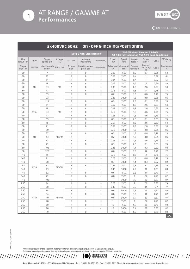
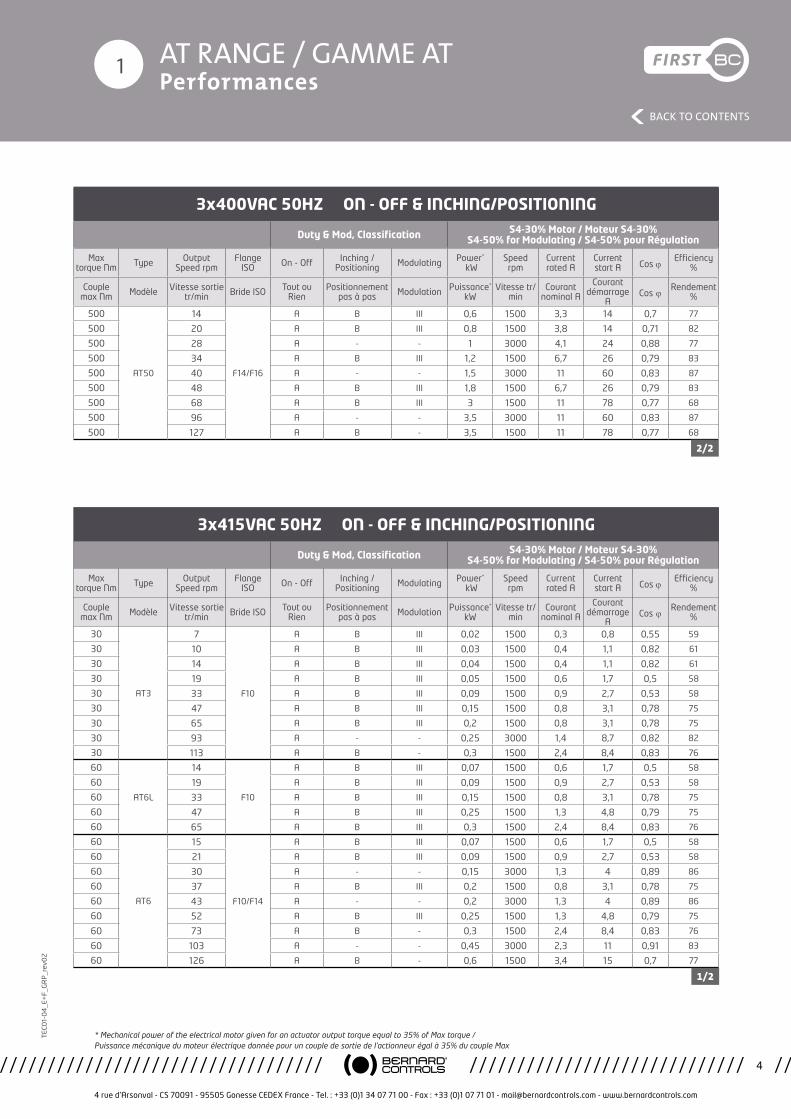
3x400VAC 50HZ ON - OFF & INCHING/POSITIONING
Duty & Mod, Classification S4-30% Motor / Moteur S4-30% S4-50% for Modulating / S4-50% pour Régulation
Max torque Nm Type Output
Speed rpmFlange
ISO On - Off Inching /Positioning Modulating Power*
kWSpeedrpm
Currentrated A
Currentstart A Cos j
Efficiency%
Couple max Nm Modèle Vitesse sortie
tr/min Bride ISO Tout ou Rien
Positionnement pas à pas Modulation Puissance*
kWVitesse tr/
minCourant
nominal A
Courant démarrage
ACos j Rendement
%
30
AT3
7
F10
A B III 0,02 1500 0,2 0,7 0,55 59
30 10 A B III 0,03 1500 0,4 1 0,82 61
30 14 A B III 0,04 1500 0,4 1 0,82 61
30 19 A B III 0,05 1500 0,6 1,6 0,50 58
30 33 A B III 0,09 1500 0,9 2,6 0,53 58
30 47 A B III 0,15 1500 0,8 3 0,78 75
30 65 A B III 0,2 1500 1,2 4,6 0,79 75
30 93 A - - 0,25 3000 1,3 3,8 0,89 86
30 113 A B - 0,3 1500 2,3 8,1 0,83 76
60
AT6L
14
F10
A B III 0,07 1500 0,9 2,6 0,53 58
60 19 A B III 0,09 1500 0,9 2,6 0,53 58
60 33 A B III 0,15 1500 1,2 4,6 0,79 75
60 47 A B III 0,25 1500 1,2 4,6 0,79 75
60 65 A B III 0,3 1500 2,3 8,1 0,83 76
60
AT6
15
F10/F14
A B III 0,07 1500 0,9 2,6 0,53 58
60 21 A B III 0,09 1500 0,9 2,6 0,53 58
60 30 A - - 0,15 3000 1,3 3,8 0,89 86
60 37 A B III 0,2 1500 1,2 4,6 0,79 75
60 43 A - - 0,2 3000 1,3 3,8 0,89 86
60 52 A B III 0,25 1500 1,2 4,6 0,79 75
60 73 A B - 0,3 1500 2,3 8,1 0,83 76
60 103 A - - 0,45 3000 1,4 8,3 0,82 82
60 126 A B - 0,6 1500 3,3 14 0,70 77
140
AT14
15
F10/F14
A B III 0,15 1500 0,8 3 0,78 75
140 21 A B III 0,25 1500 1,2 4,6 0,79 75
140 30 A - - 0,3 3000 1,4 8,3 0,82 82
140 37 A B III 0,45 1500 2,3 8,1 0,83 76
140 43 A - - 0,45 3000 2,2 11 0,91 83
140 52 A B III 0,6 1500 3,3 14 0,70 77
140 73 A B - 0,8 1500 6 22 0,71 82
140 103 A - - 1 3000 3,7 20 0,87 87
250
AT25
14
F14/F16
A B III 0,25 1500 2 7,2 0,85 79
250 20 A B III 0,45 1500 3,3 14 0,7 77
250 28 A - - 0,6 3000 2,2 11 0,91 83
250 34 A B III 0,6 1500 3,8 14 0,71 82
250 40 A - - 0,8 3000 3,7 20 0,87 87
250 48 A B III 1 1500 6 22 0,71 82
250 68 A B III 1,2 1500 6,7 26 0,79 83
250 96 A - - 1,8 3000 7,4 37 0,85 87
250 127 A B - 1,8 1500 6,7 26 0,79 83
1/2
* Mechanical power of the electrical motor given for an actuator output torque equal to 35% of Max torque / Puissance mécanique du moteur électrique donnée pour un couple de sortie de l’actionneur égal à 35% du couple Max
AT RANGE / GAMME AT Performances
4 rue d’Arsonval - CS 70091 - 95505 Gonesse CEDEX France - Tel. : +33 (0)1 34 07 71 00 - Fax : +33 (0)1 07 71 01 - [email protected] - www.bernardcontrols.com
4
BACK TO CONTENTS
TEC
01-
04
_E+
F_G
RP
_rev
02
1
3x400VAC 50HZ ON - OFF & INCHING/POSITIONING
Duty & Mod, Classification S4-30% Motor / Moteur S4-30% S4-50% for Modulating / S4-50% pour Régulation
Max torque Nm Type Output
Speed rpmFlange
ISO On - Off Inching /Positioning Modulating Power*
kWSpeedrpm
Currentrated A
Currentstart A Cos j
Efficiency%
Couple max Nm Modèle Vitesse sortie
tr/min Bride ISO Tout ou Rien
Positionnement pas à pas Modulation Puissance*
kWVitesse tr/
minCourant
nominal A
Courant démarrage
ACos j Rendement
%
500
AT50
14
F14/F16
A B III 0,6 1500 3,3 14 0,7 77
500 20 A B III 0,8 1500 3,8 14 0,71 82
500 28 A - - 1 3000 4,1 24 0,88 77
500 34 A B III 1,2 1500 6,7 26 0,79 83
500 40 A - - 1,5 3000 11 60 0,83 87
500 48 A B III 1,8 1500 6,7 26 0,79 83
500 68 A B III 3 1500 11 78 0,77 68
500 96 A - - 3,5 3000 11 60 0,83 87
500 127 A B - 3,5 1500 11 78 0,77 68
3x415VAC 50HZ ON - OFF & INCHING/POSITIONING
Duty & Mod, Classification S4-30% Motor / Moteur S4-30% S4-50% for Modulating / S4-50% pour Régulation
Max torque Nm Type Output
Speed rpmFlange
ISO On - Off Inching /Positioning Modulating Power*
kWSpeedrpm
Currentrated A
Currentstart A Cos j
Efficiency%
Couple max Nm Modèle Vitesse sortie
tr/min Bride ISO Tout ou Rien
Positionnement pas à pas Modulation Puissance*
kWVitesse tr/
minCourant
nominal A
Courant démarrage
ACos j Rendement
%
30
AT3
7
F10
A B III 0,02 1500 0,3 0,8 0,55 59
30 10 A B III 0,03 1500 0,4 1,1 0,82 61
30 14 A B III 0,04 1500 0,4 1,1 0,82 61
30 19 A B III 0,05 1500 0,6 1,7 0,5 58
30 33 A B III 0,09 1500 0,9 2,7 0,53 58
30 47 A B III 0,15 1500 0,8 3,1 0,78 75
30 65 A B III 0,2 1500 0,8 3,1 0,78 75
30 93 A - - 0,25 3000 1,4 8,7 0,82 82
30 113 A B - 0,3 1500 2,4 8,4 0,83 76
60
AT6L
14
F10
A B III 0,07 1500 0,6 1,7 0,5 58
60 19 A B III 0,09 1500 0,9 2,7 0,53 58
60 33 A B III 0,15 1500 0,8 3,1 0,78 75
60 47 A B III 0,25 1500 1,3 4,8 0,79 75
60 65 A B III 0,3 1500 2,4 8,4 0,83 76
60
AT6
15
F10/F14
A B III 0,07 1500 0,6 1,7 0,5 58
60 21 A B III 0,09 1500 0,9 2,7 0,53 58
60 30 A - - 0,15 3000 1,3 4 0,89 86
60 37 A B III 0,2 1500 0,8 3,1 0,78 75
60 43 A - - 0,2 3000 1,3 4 0,89 86
60 52 A B III 0,25 1500 1,3 4,8 0,79 75
60 73 A B - 0,3 1500 2,4 8,4 0,83 76
60 103 A - - 0,45 3000 2,3 11 0,91 83
60 126 A B - 0,6 1500 3,4 15 0,7 77
2/2
1/2
* Mechanical power of the electrical motor given for an actuator output torque equal to 35% of Max torque / Puissance mécanique du moteur électrique donnée pour un couple de sortie de l’actionneur égal à 35% du couple Max
AT RANGE / GAMME AT Performances
4 rue d’Arsonval - CS 70091 - 95505 Gonesse CEDEX France - Tel. : +33 (0)1 34 07 71 00 - Fax : +33 (0)1 07 71 01 - [email protected] - www.bernardcontrols.com
5
BACK TO CONTENTS
TEC
01-
04
_E+
F_G
RP
_rev
02
1
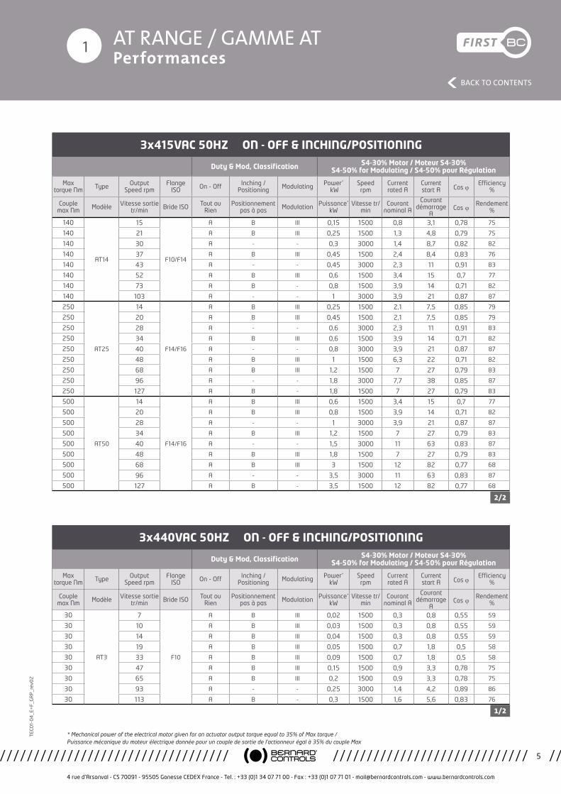
3x415VAC 50HZ ON - OFF & INCHING/POSITIONING
Duty & Mod, Classification S4-30% Motor / Moteur S4-30% S4-50% for Modulating / S4-50% pour Régulation
Max torque Nm Type Output
Speed rpmFlange
ISO On - Off Inching /Positioning Modulating Power*
kWSpeedrpm
Currentrated A
Currentstart A Cos j
Efficiency%
Couple max Nm Modèle Vitesse sortie
tr/min Bride ISO Tout ou Rien
Positionnement pas à pas Modulation Puissance*
kWVitesse tr/
minCourant
nominal A
Courant démarrage
ACos j Rendement
%
140
AT14
15
F10/F14
A B III 0,15 1500 0,8 3,1 0,78 75
140 21 A B III 0,25 1500 1,3 4,8 0,79 75
140 30 A - - 0,3 3000 1,4 8,7 0,82 82
140 37 A B III 0,45 1500 2,4 8,4 0,83 76
140 43 A - - 0,45 3000 2,3 11 0,91 83
140 52 A B III 0,6 1500 3,4 15 0,7 77
140 73 A B - 0,8 1500 3,9 14 0,71 82
140 103 A - - 1 3000 3,9 21 0,87 87
250
AT25
14
F14/F16
A B III 0,25 1500 2,1 7,5 0,85 79
250 20 A B III 0,45 1500 2,1 7,5 0,85 79
250 28 A - - 0,6 3000 2,3 11 0,91 83
250 34 A B III 0,6 1500 3,9 14 0,71 82
250 40 A - - 0,8 3000 3,9 21 0,87 87
250 48 A B III 1 1500 6,3 22 0,71 82
250 68 A B III 1,2 1500 7 27 0,79 83
250 96 A - - 1,8 3000 7,7 38 0,85 87
250 127 A B - 1,8 1500 7 27 0,79 83
500
AT50
14
F14/F16
A B III 0,6 1500 3,4 15 0,7 77
500 20 A B III 0,8 1500 3,9 14 0,71 82
500 28 A - - 1 3000 3,9 21 0,87 87
500 34 A B III 1,2 1500 7 27 0,79 83
500 40 A - - 1,5 3000 11 63 0,83 87
500 48 A B III 1,8 1500 7 27 0,79 83
500 68 A B III 3 1500 12 82 0,77 68
500 96 A - - 3,5 3000 11 63 0,83 87
500 127 A B - 3,5 1500 12 82 0,77 68
3x440VAC 50HZ ON - OFF & INCHING/POSITIONING
Duty & Mod, Classification S4-30% Motor / Moteur S4-30% S4-50% for Modulating / S4-50% pour Régulation
Max torque Nm Type Output
Speed rpmFlange
ISO On - Off Inching /Positioning Modulating Power*
kWSpeedrpm
Currentrated A
Currentstart A Cos j
Efficiency%
Couple max Nm Modèle Vitesse sortie
tr/min Bride ISO Tout ou Rien
Positionnement pas à pas Modulation Puissance*
kWVitesse tr/
minCourant
nominal A
Courant démarrage
ACos j Rendement
%
30
AT3
7
F10
A B III 0,02 1500 0,3 0,8 0,55 59
30 10 A B III 0,03 1500 0,3 0,8 0,55 59
30 14 A B III 0,04 1500 0,3 0,8 0,55 59
30 19 A B III 0,05 1500 0,7 1,8 0,5 58
30 33 A B III 0,09 1500 0,7 1,8 0,5 58
30 47 A B III 0,15 1500 0,9 3,3 0,78 75
30 65 A B III 0,2 1500 0,9 3,3 0,78 75
30 93 A - - 0,25 3000 1,4 4,2 0,89 86
30 113 A B - 0,3 1500 1,6 5,6 0,83 76
2/2
1/2
* Mechanical power of the electrical motor given for an actuator output torque equal to 35% of Max torque / Puissance mécanique du moteur électrique donnée pour un couple de sortie de l’actionneur égal à 35% du couple Max
AT RANGE / GAMME AT Performances
4 rue d’Arsonval - CS 70091 - 95505 Gonesse CEDEX France - Tel. : +33 (0)1 34 07 71 00 - Fax : +33 (0)1 07 71 01 - [email protected] - www.bernardcontrols.com
6
BACK TO CONTENTS
TEC
01-
04
_E+
F_G
RP
_rev
02
1
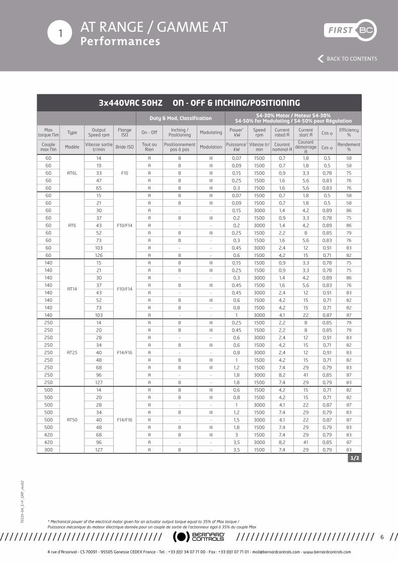
3x440VAC 50HZ ON - OFF & INCHING/POSITIONING
Duty & Mod, Classification S4-30% Motor / Moteur S4-30% S4-50% for Modulating / S4-50% pour Régulation
Max torque Nm Type Output
Speed rpmFlange
ISO On - Off Inching /Positioning Modulating Power*
kWSpeedrpm
Currentrated A
Currentstart A Cos j
Efficiency%
Couple max Nm Modèle Vitesse sortie
tr/min Bride ISO Tout ou Rien
Positionnement pas à pas Modulation Puissance*
kWVitesse tr/
minCourant
nominal A
Courant démarrage
ACos j Rendement
%
60
AT6L
14
F10
A B III 0,07 1500 0,7 1,8 0,5 58
60 19 A B III 0,09 1500 0,7 1,8 0,5 58
60 33 A B III 0,15 1500 0,9 3,3 0,78 75
60 47 A B III 0,25 1500 1,6 5,6 0,83 76
60 65 A B III 0,3 1500 1,6 5,6 0,83 76
60
AT6
15
F10/F14
A B III 0,07 1500 0,7 1,8 0,5 58
60 21 A B III 0,09 1500 0,7 1,8 0,5 58
60 30 A - - 0,15 3000 1,4 4,2 0,89 86
60 37 A B III 0,2 1500 0,9 3,3 0,78 75
60 43 A - - 0,2 3000 1,4 4,2 0,89 86
60 52 A B III 0,25 1500 2,2 8 0,85 79
60 73 A B - 0,3 1500 1,6 5,6 0,83 76
60 103 A - - 0,45 3000 2,4 12 0,91 83
60 126 A B - 0,6 1500 4,2 15 0,71 82
140
AT14
15
F10/F14
A B III 0,15 1500 0,9 3,3 0,78 75
140 21 A B III 0,25 1500 0,9 3,3 0,78 75
140 30 A - - 0,3 3000 1,4 4,2 0,89 86
140 37 A B III 0,45 1500 1,6 5,6 0,83 76
140 43 A - - 0,45 3000 2,4 12 0,91 83
140 52 A B III 0,6 1500 4,2 15 0,71 82
140 73 A B - 0,8 1500 4,2 15 0,71 82
140 103 A - - 1 3000 4,1 22 0,87 87
250
AT25
14
F14/F16
A B III 0,25 1500 2,2 8 0,85 79
250 20 A B III 0,45 1500 2,2 8 0,85 79
250 28 A - - 0,6 3000 2,4 12 0,91 83
250 34 A B III 0,6 1500 4,2 15 0,71 82
250 40 A - - 0,8 3000 2,4 12 0,91 83
250 48 A B III 1 1500 4,2 15 0,71 82
250 68 A B III 1,2 1500 7,4 29 0,79 83
250 96 A - - 1,8 3000 8,2 41 0,85 87
250 127 A B - 1,8 1500 7,4 29 0,79 83
500
AT50
14
F14/F16
A B III 0,6 1500 4,2 15 0,71 82
500 20 A B III 0,8 1500 4,2 15 0,71 82
500 28 A - - 1 3000 4,1 22 0,87 87
500 34 A B III 1,2 1500 7,4 29 0,79 83
500 40 A - - 1,5 3000 4,1 22 0,87 87
500 48 A B III 1,8 1500 7,4 29 0,79 83
420 68 A B III 3 1500 7,4 29 0,79 83
420 96 A - - 3,5 3000 8,2 41 0,85 87
300 127 A B - 3,5 1500 7,4 29 0,79 83
1/2
* Mechanical power of the electrical motor given for an actuator output torque equal to 35% of Max torque / Puissance mécanique du moteur électrique donnée pour un couple de sortie de l’actionneur égal à 35% du couple Max
AT RANGE / GAMME AT Performances
4 rue d’Arsonval - CS 70091 - 95505 Gonesse CEDEX France - Tel. : +33 (0)1 34 07 71 00 - Fax : +33 (0)1 07 71 01 - [email protected] - www.bernardcontrols.com
7
BACK TO CONTENTS
TEC
01-
04
_E+
F_G
RP
_rev
02
1
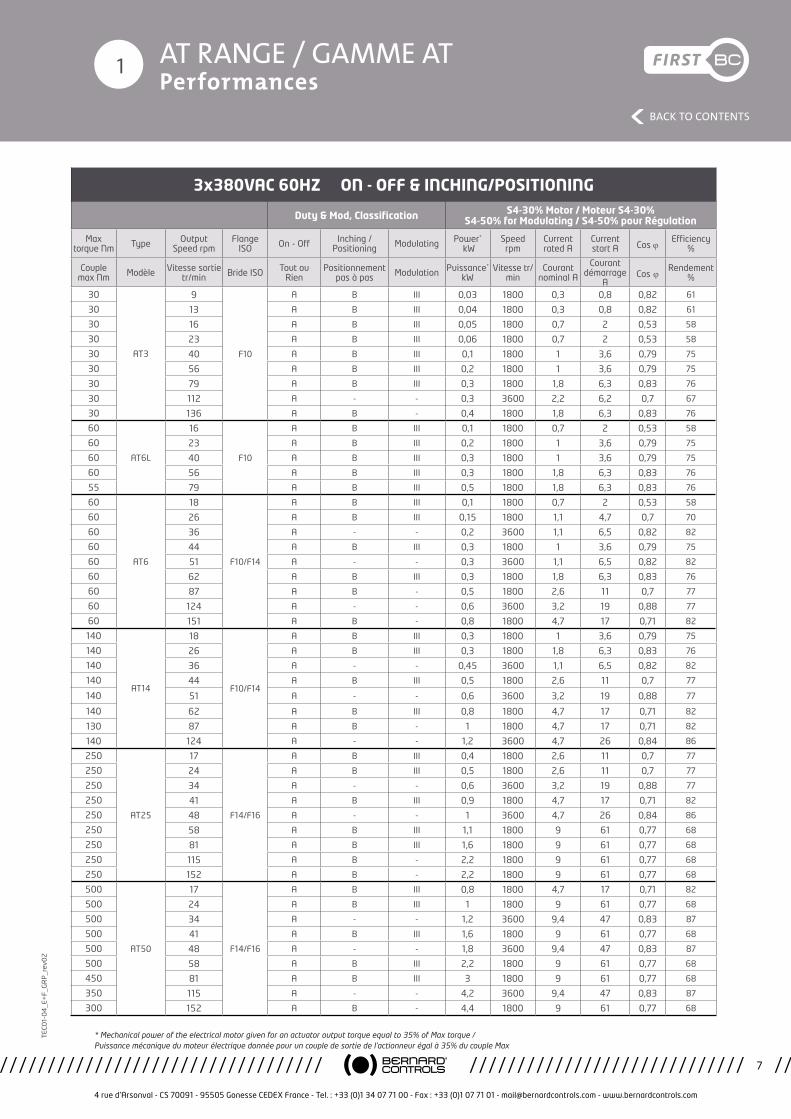
3x380VAC 60HZ ON - OFF & INCHING/POSITIONING
Duty & Mod, Classification S4-30% Motor / Moteur S4-30% S4-50% for Modulating / S4-50% pour Régulation
Max torque Nm Type Output
Speed rpmFlange
ISO On - Off Inching /Positioning Modulating Power*
kWSpeedrpm
Currentrated A
Currentstart A Cos j
Efficiency%
Couple max Nm Modèle Vitesse sortie
tr/min Bride ISO Tout ou Rien
Positionnement pas à pas Modulation Puissance*
kWVitesse tr/
minCourant
nominal A
Courant démarrage
ACos j Rendement
%
30
AT3
9
F10
A B III 0,03 1800 0,3 0,8 0,82 61
30 13 A B III 0,04 1800 0,3 0,8 0,82 61
30 16 A B III 0,05 1800 0,7 2 0,53 58
30 23 A B III 0,06 1800 0,7 2 0,53 58
30 40 A B III 0,1 1800 1 3,6 0,79 75
30 56 A B III 0,2 1800 1 3,6 0,79 75
30 79 A B III 0,3 1800 1,8 6,3 0,83 76
30 112 A - - 0,3 3600 2,2 6,2 0,7 67
30 136 A B - 0,4 1800 1,8 6,3 0,83 76
60
AT6L
16
F10
A B III 0,1 1800 0,7 2 0,53 58
60 23 A B III 0,2 1800 1 3,6 0,79 75
60 40 A B III 0,3 1800 1 3,6 0,79 75
60 56 A B III 0,3 1800 1,8 6,3 0,83 76
55 79 A B III 0,5 1800 1,8 6,3 0,83 76
60
AT6
18
F10/F14
A B III 0,1 1800 0,7 2 0,53 58
60 26 A B III 0,15 1800 1,1 4,7 0,7 70
60 36 A - - 0,2 3600 1,1 6,5 0,82 82
60 44 A B III 0,3 1800 1 3,6 0,79 75
60 51 A - - 0,3 3600 1,1 6,5 0,82 82
60 62 A B III 0,3 1800 1,8 6,3 0,83 76
60 87 A B - 0,5 1800 2,6 11 0,7 77
60 124 A - - 0,6 3600 3,2 19 0,88 77
60 151 A B - 0,8 1800 4,7 17 0,71 82
140
AT14
18
F10/F14
A B III 0,3 1800 1 3,6 0,79 75
140 26 A B III 0,3 1800 1,8 6,3 0,83 76
140 36 A - - 0,45 3600 1,1 6,5 0,82 82
140 44 A B III 0,5 1800 2,6 11 0,7 77
140 51 A - - 0,6 3600 3,2 19 0,88 77
140 62 A B III 0,8 1800 4,7 17 0,71 82
130 87 A B - 1 1800 4,7 17 0,71 82
140 124 A - - 1,2 3600 4,7 26 0,84 86
250
AT25
17
F14/F16
A B III 0,4 1800 2,6 11 0,7 77
250 24 A B III 0,5 1800 2,6 11 0,7 77
250 34 A - - 0,6 3600 3,2 19 0,88 77
250 41 A B III 0,9 1800 4,7 17 0,71 82
250 48 A - - 1 3600 4,7 26 0,84 86
250 58 A B III 1,1 1800 9 61 0,77 68
250 81 A B III 1,6 1800 9 61 0,77 68
250 115 A B - 2,2 1800 9 61 0,77 68
250 152 A B - 2,2 1800 9 61 0,77 68
500
AT50
17
F14/F16
A B III 0,8 1800 4,7 17 0,71 82
500 24 A B III 1 1800 9 61 0,77 68
500 34 A - - 1,2 3600 9,4 47 0,83 87
500 41 A B III 1,6 1800 9 61 0,77 68
500 48 A - - 1,8 3600 9,4 47 0,83 87
500 58 A B III 2,2 1800 9 61 0,77 68
450 81 A B III 3 1800 9 61 0,77 68
350 115 A - - 4,2 3600 9,4 47 0,83 87
300 152 A B - 4,4 1800 9 61 0,77 68
* Mechanical power of the electrical motor given for an actuator output torque equal to 35% of Max torque / Puissance mécanique du moteur électrique donnée pour un couple de sortie de l’actionneur égal à 35% du couple Max
AT RANGE / GAMME AT Performances
4 rue d’Arsonval - CS 70091 - 95505 Gonesse CEDEX France - Tel. : +33 (0)1 34 07 71 00 - Fax : +33 (0)1 07 71 01 - [email protected] - www.bernardcontrols.com
8
BACK TO CONTENTS
TEC
01-
04
_E+
F_G
RP
_rev
02
1
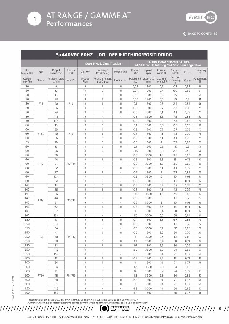
3x440VAC 60HZ ON - OFF & INCHING/POSITIONING
Duty & Mod, Classification S4-30% Motor / Moteur S4-30% S4-50% for Modulating / S4-50% pour Régulation
Max torque Nm Type Output
Speed rpmFlange
ISO On - Off Inching /Positioning Modulating Power*
kWSpeedrpm
Currentrated A
Currentstart A Cos j
Efficiency%
Couple max Nm Modèle Vitesse sortie
tr/min Bride ISO Tout ou Rien
Positionnement pas à pas Modulation Puissance*
kWVitesse tr/
minCourant
nominal A
Courant démarrage
ACos j Rendement
%
30
AT3
9
F10
A B III 0,03 1800 0,2 0,7 0,55 59
30 13 A B III 0,04 1800 0,4 0,9 0,82 61
30 16 A B III 0,05 1800 0,6 1,5 0,5 58
30 23 A B III 0,06 1800 0,6 1,5 0,5 58
30 40 A B III 0,1 1800 0,8 2,3 0,53 58
30 56 A B III 0,2 1800 0,7 2,7 0,78 75
30 79 A B III 0,3 1800 1,1 4,1 0,79 75
30 112 A - - 0,3 3600 1,2 7,5 0,82 82
30 136 A B - 0,4 1800 2 7,3 0,83 76
60
AT6L
16
F10
A B III 0,1 1800 0,8 2,3 0,53 58
60 23 A B III 0,2 1800 0,7 2,7 0,78 75
60 40 A B III 0,3 1800 1,1 4,1 0,79 75
60 56 A B III 0,3 1800 1,1 4,1 0,79 75
55 79 A B III 0,5 1800 2 7,3 0,83 76
60
AT6
18
F10/F14
A B III 0,1 1800 0,6 1,5 0,5 58
60 26 A B III 0,15 1800 0,8 2,3 0,53 58
60 36 A - - 0,2 3600 1,2 3,5 0,89 86
60 44 A B III 0,3 1800 3,5 13 0,71 82
60 51 A - - 0,3 3600 1,2 3,5 0,89 86
60 62 A B III 0,3 1800 1,1 4,1 0,79 75
60 87 A B - 0,5 1800 2 7,3 0,83 76
60 124 A - - 0,6 3600 2 10 0,91 83
60 151 A B - 0,8 1800 3,5 13 0,71 82
140
AT14
18
F10/F14
A B III 0,3 1800 0,7 2,7 0,78 75
140 26 A B III 0,3 1800 1,1 4,1 0,79 75
140 36 A - - 0,45 3600 1,2 7,5 0,82 82
140 44 A B III 0,5 1800 3 13 0,7 77
140 51 A - - 0,6 3600 2 10 0,91 83
140 62 A B III 0,8 1800 3,5 13 0,71 82
140 87 A B - 1 1800 5,4 20 0,71 82
140 124 A - - 1,2 3600 5,5 30 0,84 86
250
AT25
17
F14/F16
A B III 0,4 1800 1,8 6,7 0,85 79
250 24 A B III 0,5 1800 3 13 0,7 77
250 34 A - - 0,6 3600 3,7 22 0,88 77
250 41 A B III 0,9 1800 6,2 24 0,79 83
250 48 A - - 1 3600 3,4 19 0,87 87
250 58 A B III 1,1 1800 5,4 20 0,71 82
250 81 A B III 1,6 1800 6,2 24 0,79 83
250 115 A - - 2,2 3600 6,8 34 0,85 87
250 152 A B - 2,2 1800 10 71 0,77 68
500
AT50
17
F14/F16
A B III 0,8 1800 3,5 13 0,71 82
500 24 A B III 1 1800 10 71 0,77 68
500 34 A - - 1,2 3600 6,8 34 0,85 87
500 41 A B III 1,6 1800 6,2 24 0,79 83
500 48 A - - 1,8 3600 6,8 34 0,85 87
500 58 A B III 2,2 1800 10 71 0,77 68
500 81 A B III 3 1800 10 71 0,77 68
450 115 A - - 4,2 3600 10 54 0,83 87
400 152 A B - 4,4 1800 11 78 0,77 68
* Mechanical power of the electrical motor given for an actuator output torque equal to 35% of Max torque / Puissance mécanique du moteur électrique donnée pour un couple de sortie de l’actionneur égal à 35% du couple Max
AT RANGE / GAMME AT Performances
4 rue d’Arsonval - CS 70091 - 95505 Gonesse CEDEX France - Tel. : +33 (0)1 34 07 71 00 - Fax : +33 (0)1 07 71 01 - [email protected] - www.bernardcontrols.com
9
BACK TO CONTENTS
TEC
01-
04
_E+
F_G
RP
_rev
02
1
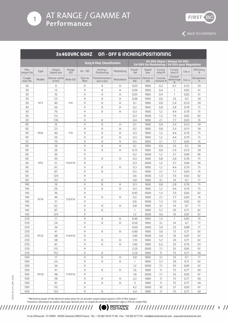
3x460VAC 60HZ ON - OFF & INCHING/POSITIONING
Duty & Mod, Classification S4-30% Motor / Moteur S4-30% S4-50% for Modulating / S4-50% pour Régulation
Max torque Nm Type Output
Speed rpmFlange
ISO On - Off Inching /Positioning Modulating Power*
kWSpeedrpm
Currentrated A
Currentstart A Cos j
Efficiency%
Couple max Nm Modèle Vitesse sortie
tr/min Bride ISO Tout ou Rien
Positionnement pas à pas Modulation Puissance*
kWVitesse tr/
minCourant
nominal A
Courant démarrage
ACos j Rendement
%
30
AT3
9
F10
A B III 0,03 1800 0,2 0,7 0,55 59
30 13 A B III 0,04 1800 0,4 1 0,82 61
30 16 A B III 0,05 1800 0,4 1 0,82 61
30 23 A B III 0,06 1800 0,6 1,6 0,5 58
30 40 A B III 0,1 1800 0,8 2,4 0,53 58
30 56 A B III 0,2 1800 0,8 2,8 0,78 75
30 79 A B III 0,3 1800 1,2 4,4 0,79 75
30 112 A - - 0,3 3600 1,3 7,9 0,82 82
30 136 A B - 0,4 1800 2,1 7,7 0,83 76
60
AT6L
16
F10
A B III 0,1 1800 0,8 2,4 0,53 58
60 23 A B III 0,2 1800 0,8 2,4 0,53 58
60 40 A B III 0,3 1800 1,2 4,4 0,79 75
60 56 A B III 0,3 1800 1,2 4,4 0,79 75
55 79 A B III 0,5 1800 2,1 7,7 0,83 76
60
AT6
18
F10/F14
A B III 0,1 1800 0,6 1,6 0,5 58
60 26 A B III 0,15 1800 0,8 2,4 0,53 58
60 36 A - - 0,2 3600 1,2 3,7 0,89 86
60 44 A B III 0,3 1800 0,8 2,8 0,78 75
60 51 A - - 0,3 3600 1,2 3,7 0,89 86
60 62 A B III 0,3 1800 1,2 4,4 0,79 75
60 87 A B - 0,5 1800 2,1 7,7 0,83 76
60 124 A - - 0,6 3600 1,3 7,9 0,82 82
60 151 A B - 0,8 1800 3,1 14 0,7 77
140
AT14
18
F10/F14
A B III 0,3 1800 0,8 2,8 0,78 75
140 26 A B III 0,3 1800 1,2 4,4 0,79 75
140 36 A - - 0,45 3600 1,3 7,9 0,82 82
140 44 A B III 0,5 1800 2,1 7,7 0,83 76
140 51 A - - 0,6 3600 1,3 7,9 0,82 82
140 62 A B III 0,8 1800 3,1 14 0,7 77
140 87 A B - 1 1800 5,7 20 0,71 82
140 124 A - - 1,2 3600 3,6 19 0,87 87
250
AT25
17
F14/F16
A B III 0,40 1800 1,9 7 0,85 79
250 24 A B III 0,50 1800 3,1 14 0,7 77
250 34 A - - 0,60 3600 3,9 23 0,88 77
250 41 A B III 0,90 1800 3,6 13 0,71 82
250 48 A - - 1,00 3600 3,6 19 0,87 87
250 58 A B III 1,10 1800 5,7 20 0,71 82
250 81 A B III 1,60 1800 6,5 25 0,79 83
250 115 A - - 2,20 3600 7,1 35 0,85 87
250 152 A B - 2,20 1800 11 75 0,77 68
500
AT50
17
F14/F16
A B III 0,8 1800 3,1 14 0,7 77
500 24 A B III 1 1800 5,7 20 0,71 82
500 34 A - - 1,2 3600 7,1 35 0,85 87
500 41 A B III 1,6 1800 11 75 0,77 68
500 48 A - - 1,8 3600 7,1 35 0,85 87
500 58 A B III 2,2 1800 11 75 0,77 68
500 81 A B III 3 1800 11 75 0,77 68
500 115 A - - 4,2 3600 10 57 0,83 87
450 152 A B - 4,4 1800 11 75 0,77 68
* Mechanical power of the electrical motor given for an actuator output torque equal to 35% of Max torque / Puissance mécanique du moteur électrique donnée pour un couple de sortie de l’actionneur égal à 35% du couple Max
AT RANGE / GAMME AT Performances
4 rue d’Arsonval - CS 70091 - 95505 Gonesse CEDEX France - Tel. : +33 (0)1 34 07 71 00 - Fax : +33 (0)1 07 71 01 - [email protected] - www.bernardcontrols.com
10
BACK TO CONTENTS
TEC
01-
04
_E+
F_G
RP
_rev
02
1
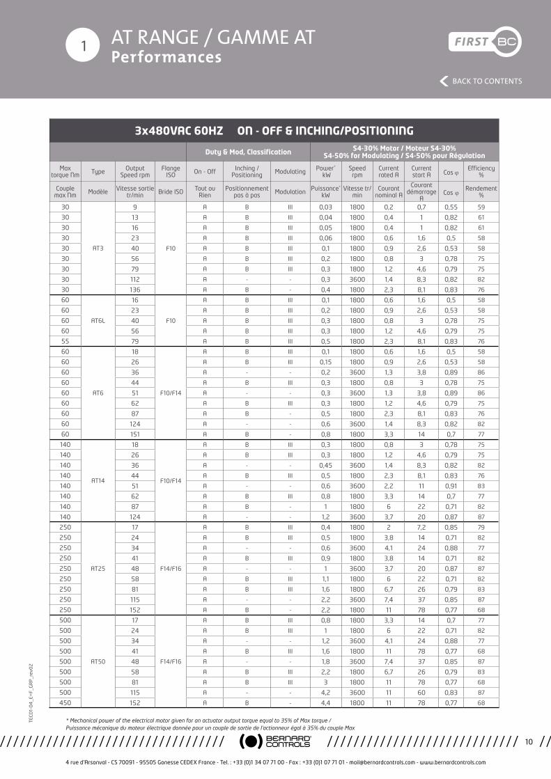
3x480VAC 60HZ ON - OFF & INCHING/POSITIONING
Duty & Mod, Classification S4-30% Motor / Moteur S4-30% S4-50% for Modulating / S4-50% pour Régulation
Max torque Nm Type Output
Speed rpmFlange
ISO On - Off Inching /Positioning Modulating Power*
kWSpeedrpm
Currentrated A
Currentstart A Cos j
Efficiency%
Couple max Nm Modèle Vitesse sortie
tr/min Bride ISO Tout ou Rien
Positionnement pas à pas Modulation Puissance*
kWVitesse tr/
minCourant
nominal A
Courant démarrage
ACos j Rendement
%
30
AT3
9
F10
A B III 0,03 1800 0,2 0,7 0,55 59
30 13 A B III 0,04 1800 0,4 1 0,82 61
30 16 A B III 0,05 1800 0,4 1 0,82 61
30 23 A B III 0,06 1800 0,6 1,6 0,5 58
30 40 A B III 0,1 1800 0,9 2,6 0,53 58
30 56 A B III 0,2 1800 0,8 3 0,78 75
30 79 A B III 0,3 1800 1,2 4,6 0,79 75
30 112 A - - 0,3 3600 1,4 8,3 0,82 82
30 136 A B - 0,4 1800 2,3 8,1 0,83 76
60
AT6L
16
F10
A B III 0,1 1800 0,6 1,6 0,5 58
60 23 A B III 0,2 1800 0,9 2,6 0,53 58
60 40 A B III 0,3 1800 0,8 3 0,78 75
60 56 A B III 0,3 1800 1,2 4,6 0,79 75
55 79 A B III 0,5 1800 2,3 8,1 0,83 76
60
AT6
18
F10/F14
A B III 0,1 1800 0,6 1,6 0,5 58
60 26 A B III 0,15 1800 0,9 2,6 0,53 58
60 36 A - - 0,2 3600 1,3 3,8 0,89 86
60 44 A B III 0,3 1800 0,8 3 0,78 75
60 51 A - - 0,3 3600 1,3 3,8 0,89 86
60 62 A B III 0,3 1800 1,2 4,6 0,79 75
60 87 A B - 0,5 1800 2,3 8,1 0,83 76
60 124 A - - 0,6 3600 1,4 8,3 0,82 82
60 151 A B - 0,8 1800 3,3 14 0,7 77
140
AT14
18
F10/F14
A B III 0,3 1800 0,8 3 0,78 75
140 26 A B III 0,3 1800 1,2 4,6 0,79 75
140 36 A - - 0,45 3600 1,4 8,3 0,82 82
140 44 A B III 0,5 1800 2,3 8,1 0,83 76
140 51 A - - 0,6 3600 2,2 11 0,91 83
140 62 A B III 0,8 1800 3,3 14 0,7 77
140 87 A B - 1 1800 6 22 0,71 82
140 124 A - - 1,2 3600 3,7 20 0,87 87
250
AT25
17
F14/F16
A B III 0,4 1800 2 7,2 0,85 79
250 24 A B III 0,5 1800 3,8 14 0,71 82
250 34 A - - 0,6 3600 4,1 24 0,88 77
250 41 A B III 0,9 1800 3,8 14 0,71 82
250 48 A - - 1 3600 3,7 20 0,87 87
250 58 A B III 1,1 1800 6 22 0,71 82
250 81 A B III 1,6 1800 6,7 26 0,79 83
250 115 A - - 2,2 3600 7,4 37 0,85 87
250 152 A B - 2,2 1800 11 78 0,77 68
500
AT50
17
F14/F16
A B III 0,8 1800 3,3 14 0,7 77
500 24 A B III 1 1800 6 22 0,71 82
500 34 A - - 1,2 3600 4,1 24 0,88 77
500 41 A B III 1,6 1800 11 78 0,77 68
500 48 A - - 1,8 3600 7,4 37 0,85 87
500 58 A B III 2,2 1800 6,7 26 0,79 83
500 81 A B III 3 1800 11 78 0,77 68
500 115 A - - 4,2 3600 11 60 0,83 87
450 152 A B - 4,4 1800 11 78 0,77 68
* Mechanical power of the electrical motor given for an actuator output torque equal to 35% of Max torque / Puissance mécanique du moteur électrique donnée pour un couple de sortie de l’actionneur égal à 35% du couple Max

AT RANGE / GAMME AT Performances
4 rue d’Arsonval - CS 70091 - 95505 Gonesse CEDEX France - Tel. : +33 (0)1 34 07 71 00 - Fax : +33 (0)1 07 71 01 - [email protected] - www.bernardcontrols.com
11
BACK TO CONTENTS
TEC
01-
04
_E+
F_G
RP
_rev
02
1
1x230VAC 50HZ ON - OFF & INCHING/POSITIONING
Duty & Mod, Classification S4-30% Motor / Moteur S4-30% S4-50% for Modulating / S4-50% pour Régulation
Max torque Nm Type Output
Speed rpmFlange
ISO On - Off Inching /Positioning Modulating Power*
kWSpeedrpm
Currentrated A
Currentstart A Cos j
Efficiency%
Couple max Nm Modèle Vitesse sortie
tr/min Bride ISO Tout ou Rien
Positionnement pas à pas Modulation Puissance*
kWVitesse tr/
minCourant
nominal A
Courant démarrage
ACos j Rendement
%
30
AT3
7
F10
A B III 0,02 1500 0,8 3,4 1,1 69
30 10 A B III 0,03 1500 0,8 3,4 1,1 69
30 14 A B III 0,04 1500 0,8 3,4 1,1 69
30 19 A B III 0,05 1500 2,5 4,6 0,98 67
30 33 A B III 0,09 1500 5,3 11 1 69
30 47 A B III 0,15 1500 5,3 11 1 69
30 65 A B III 0,2 1500 5,3 11 1 69
30 93 A - - 0,25 3000 4,5 12 0,9 52
30 113 A B - 0,3 1500 5,3 11 1 69
60
AT6L
14
F10
A B III 0,07 1500 5,3 11 1 69
60 19 A B III 0,09 1500 5,3 11 1 69
60 33 A B III 0,15 1500 5,3 11 1 69
60 47 A B III 0,25 1500 5,3 11 1 69
60 65 A B III 0,3 1500 5,3 11 1 69
60
AT6
15
F10/F14
A B III 0,07 1500 5,3 11 1 69
60 21 A B III 0,09 1500 5,3 11 1 69
60 30 A - - 0,15 3000 4,2 9,3 0,95 66
60 37 A B III 0,2 1500 5,3 11 1 69
60 43 A - - 0,2 3000 19 55 0,97 75
60 52 A B III 0,25 1500 5,3 11 1 69
60 73 A B - 0,3 1500 11 34 1 76
60 103 A - - 0,45 3000 19 55 0,97 75
60 126 A B - 0,6 1500 11 34 1 76
140
AT14
15
F10/F14
A B III 0,15 1500 5,3 11 1 69
140 21 A B III 0,25 1500 5,3 11 1 69
140 30 A - - 0,3 3000 19 55 0,97 75
140 37 A B III 0,45 1500 11 34 1 76
140 43 A - - 0,45 3000 19 55 0,97 75
140 52 A B III 0,6 1500 11 34 1 76
135 73 A B - 0,8 1500 11 34 1 76
250
AT25
14
F14/F16
A B III 0,25 1500 11 34 1 76
250 20 A B III 0,45 1500 11 34 1 76
250 28 A - - 0,6 3000 19 55 0,97 75
250 34 A B III 0,6 1500 11 34 1 76
* Mechanical power of the electrical motor given for an actuator output torque equal to 35% of Max torque / Puissance mécanique du moteur électrique donnée pour un couple de sortie de l’actionneur égal à 35% du couple Max

AT RANGE / GAMME AT Performances
4 rue d’Arsonval - CS 70091 - 95505 Gonesse CEDEX France - Tel. : +33 (0)1 34 07 71 00 - Fax : +33 (0)1 07 71 01 - [email protected] - www.bernardcontrols.com
12
BACK TO CONTENTS
TEC
01-
04
_E+
F_G
RP
_rev
02
1
1x110VAC 50HZ ON - OFF & INCHING/POSITIONING
Duty & Mod, Classification S4-30% Motor / Moteur S4-30% S4-50% for Modulating / S4-50% pour Régulation
Max torque Nm Type Output
Speed rpmFlange
ISO On - Off Inching /Positioning Modulating Power*
kWSpeedrpm
Currentrated A
Currentstart A Cos j
Efficiency%
Couple max Nm Modèle Vitesse sortie
tr/min Bride ISO Tout ou Rien
Positionnement pas à pas Modulation Puissance*
kWVitesse tr/
minCourant
nominal A
Courant démarrage
ACos j Rendement
%
30
AT3
7
F10
A B III 0,02 1500 5,4 11 0,98 59
30 10 A B III 0,03 1500 5,4 11 0,98 59
30 14 A B III 0,04 1500 5,4 11 0,98 59
30 19 A B III 0,05 1500 5,4 11 0,98 59
30 33 A B III 0,09 1500 10 33 1 72
30 47 A B III 0,15 1500 10 33 1 72
30 65 A B III 0,2 1500 10 33 1 72
30 93 A - - 0,25 3000 15 61 0,98 75
30 113 A B - 0,3 1500 10 33 1 72
60
AT6L
14
F10
A B III 0,07 1500 10 33 1 72
60 19 A B III 0,09 1500 10 33 1 72
60 33 A B III 0,15 1500 10 33 1 72
60 47 A B III 0,25 1500 10 33 1 72
60 65 A B III 0,3 1500 10 33 1 72
60
AT6
15
F10/F14
A B III 0,07 1500 10 33 1 72
60 21 A B III 0,09 1500 10 33 1 72
60 30 A - - 0,15 3000 9 19 0,89 58
60 37 A B III 0,2 1500 10 33 1 72
60 43 A - - 0,2 3000 9 19 0,89 58
60 52 A B III 0,25 1500 10 33 1 72
50 73 A B - 0,3 1500 14 48 0,9 21
60 103 A - - 0,45 3000 15 61 0,98 75
140
AT14
15
F10/F14
A B III 0,15 1500 10 33 1 72
140 21 A B III 0,25 1500 10 33 1 72
140 30 A - - 0,3 3000 15 61 0,98 75
140 37 A B III 0,45 1500 21 77 1 75
140 43 A - - 0,45 3000 15 61 0,98 75
140 52 A B III 0,6 1500 21 77 1 75
140 73 A B - 0,8 1500 21 77 1 75
250
AT25
14
F14/F16
A B III 0,25 1500 21 77 1 75
250 20 A B III 0,45 1500 21 77 1 75
250 28 A - - 0,6 3000 39 142 0,91 74
250 34 A B III 0,6 1500 21 77 1 75
* Mechanical power of the electrical motor given for an actuator output torque equal to 35% of Max torque / Puissance mécanique du moteur électrique donnée pour un couple de sortie de l’actionneur égal à 35% du couple Max
AT RANGE / GAMME AT Performances
4 rue d’Arsonval - CS 70091 - 95505 Gonesse CEDEX France - Tel. : +33 (0)1 34 07 71 00 - Fax : +33 (0)1 07 71 01 - [email protected] - www.bernardcontrols.com
13
BACK TO CONTENTS
TEC
01-
04
_E+
F_G
RP
_rev
02
1
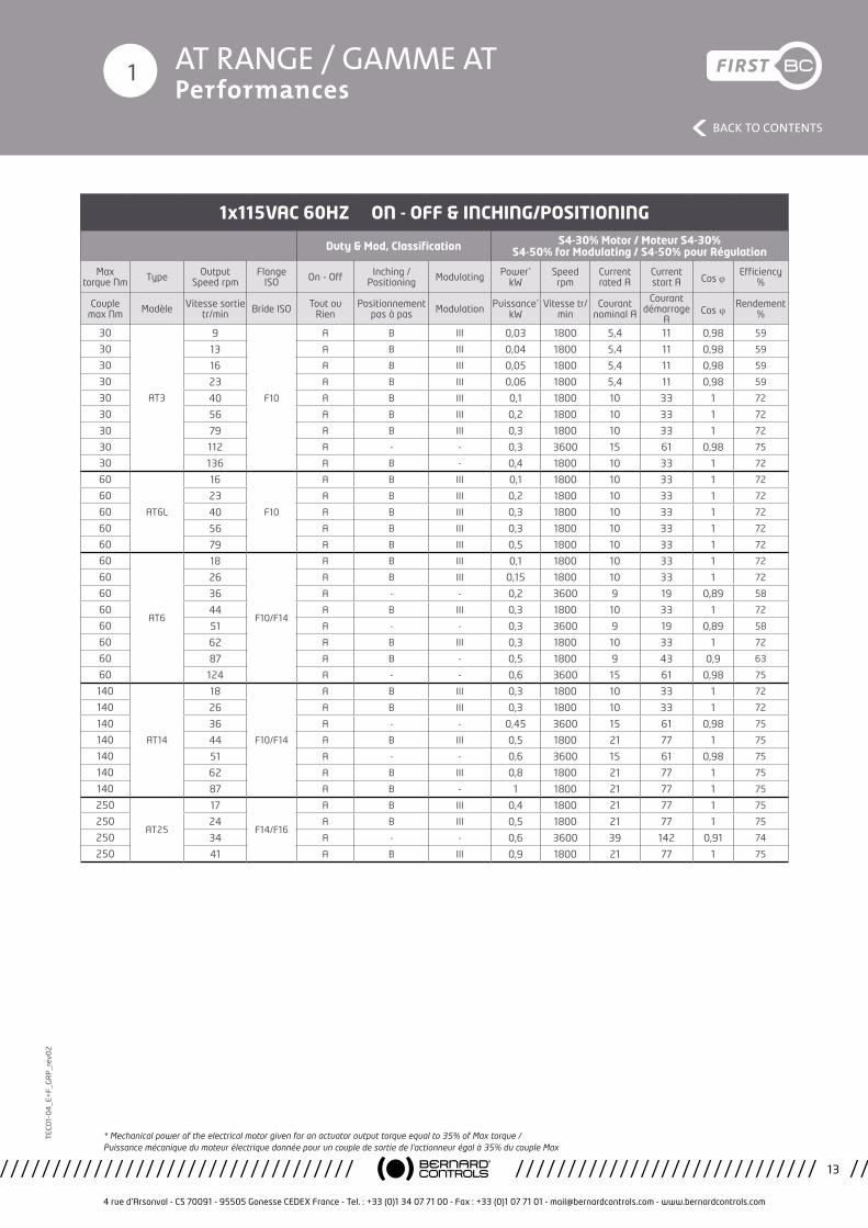
1x115VAC 60HZ ON - OFF & INCHING/POSITIONING
Duty & Mod, Classification S4-30% Motor / Moteur S4-30% S4-50% for Modulating / S4-50% pour Régulation
Max torque Nm Type Output
Speed rpmFlange
ISO On - Off Inching /Positioning Modulating Power*
kWSpeedrpm
Currentrated A
Currentstart A Cos j
Efficiency%
Couple max Nm Modèle Vitesse sortie
tr/min Bride ISO Tout ou Rien
Positionnement pas à pas Modulation Puissance*
kWVitesse tr/
minCourant
nominal A
Courant démarrage
ACos j Rendement
%
30
AT3
9
F10
A B III 0,03 1800 5,4 11 0,98 59
30 13 A B III 0,04 1800 5,4 11 0,98 59
30 16 A B III 0,05 1800 5,4 11 0,98 59
30 23 A B III 0,06 1800 5,4 11 0,98 59
30 40 A B III 0,1 1800 10 33 1 72
30 56 A B III 0,2 1800 10 33 1 72
30 79 A B III 0,3 1800 10 33 1 72
30 112 A - - 0,3 3600 15 61 0,98 75
30 136 A B - 0,4 1800 10 33 1 72
60
AT6L
16
F10
A B III 0,1 1800 10 33 1 72
60 23 A B III 0,2 1800 10 33 1 72
60 40 A B III 0,3 1800 10 33 1 72
60 56 A B III 0,3 1800 10 33 1 72
60 79 A B III 0,5 1800 10 33 1 72
60
AT6
18
F10/F14
A B III 0,1 1800 10 33 1 72
60 26 A B III 0,15 1800 10 33 1 72
60 36 A - - 0,2 3600 9 19 0,89 58
60 44 A B III 0,3 1800 10 33 1 72
60 51 A - - 0,3 3600 9 19 0,89 58
60 62 A B III 0,3 1800 10 33 1 72
60 87 A B - 0,5 1800 9 43 0,9 63
60 124 A - - 0,6 3600 15 61 0,98 75
140
AT14
18
F10/F14
A B III 0,3 1800 10 33 1 72
140 26 A B III 0,3 1800 10 33 1 72
140 36 A - - 0,45 3600 15 61 0,98 75
140 44 A B III 0,5 1800 21 77 1 75
140 51 A - - 0,6 3600 15 61 0,98 75
140 62 A B III 0,8 1800 21 77 1 75
140 87 A B - 1 1800 21 77 1 75
250
AT25
17
F14/F16
A B III 0,4 1800 21 77 1 75
250 24 A B III 0,5 1800 21 77 1 75
250 34 A - - 0,6 3600 39 142 0,91 74
250 41 A B III 0,9 1800 21 77 1 75
* Mechanical power of the electrical motor given for an actuator output torque equal to 35% of Max torque / Puissance mécanique du moteur électrique donnée pour un couple de sortie de l’actionneur égal à 35% du couple Max
4 rue d’Arsonval - CS 70091 - 95505 Gonesse CEDEX France - Tel. : +33 (0)1 34 07 71 00 - Fax : +33 (0)1 07 71 01 - [email protected] - www.bernardcontrols.com
14
BACK TO CONTENTS
TEC
01-
04
_E+
F_G
RP
_rev
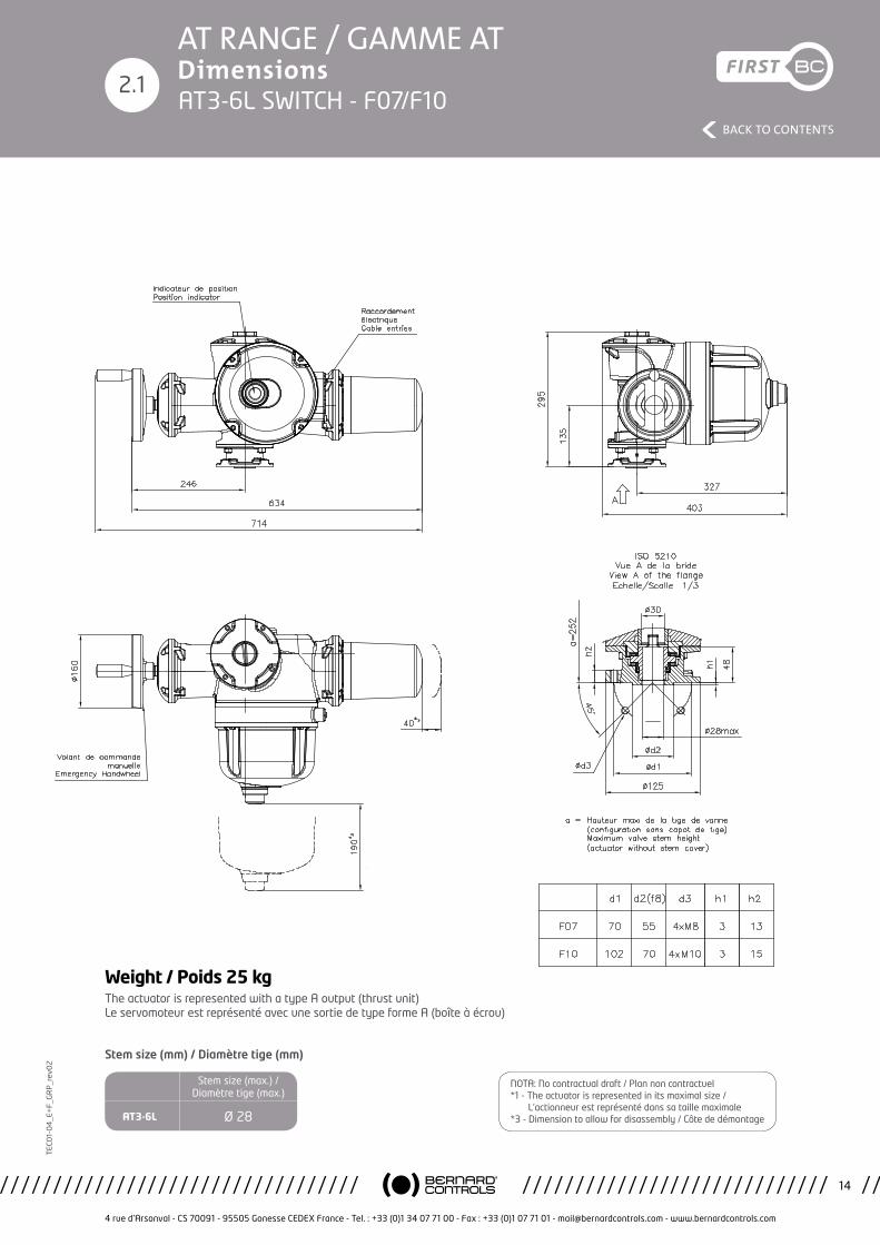
02AT RANGE / GAMME ATDimensionsAT3-6L SWITCH - F07/F10
The actuator is represented with a type A output (thrust unit) Le servomoteur est représenté avec une sortie de type forme A (boîte à écrou)
2.1
Weight / Poids 25 kg
Stem size (max.) / Diamètre tige (max.)
AT3-6L Ø 28
NOTA: No contractual draft / Plan non contractuel*1 - The actuator is represented in its maximal size / L’actionneur est représenté dans sa taille maximale*3 - Dimension to allow for disassembly / Côte de démontage
Stem size (mm) / Diamètre tige (mm)
4 rue d’Arsonval - CS 70091 - 95505 Gonesse CEDEX France - Tel. : +33 (0)1 34 07 71 00 - Fax : +33 (0)1 07 71 01 - [email protected] - www.bernardcontrols.com
15
BACK TO CONTENTS
TEC
01-
04
_E+
F_G
RP
_rev
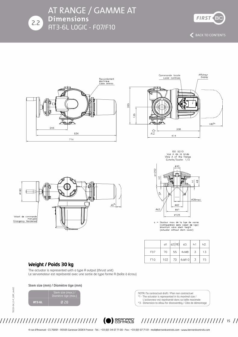
02AT RANGE / GAMME ATDimensions
2.2AT3-6L LOGIC - F07/F10
The actuator is represented with a type A output (thrust unit) Le servomoteur est représenté avec une sortie de type forme A (boîte à écrou)
Weight / Poids 30 kg
Stem size (max.) / Diamètre tige (max.)
AT3-6L Ø 28
Stem size (mm) / Diamètre tige (mm)
NOTA: No contractual draft / Plan non contractuel*1 - The actuator is represented in its maximal size / L’actionneur est représenté dans sa taille maximale*3 - Dimension to allow for disassembly / Côte de démontage
4 rue d’Arsonval - CS 70091 - 95505 Gonesse CEDEX France - Tel. : +33 (0)1 34 07 71 00 - Fax : +33 (0)1 07 71 01 - [email protected] - www.bernardcontrols.com
16
BACK TO CONTENTS
TEC
01-
04
_E+
F_G
RP
_rev
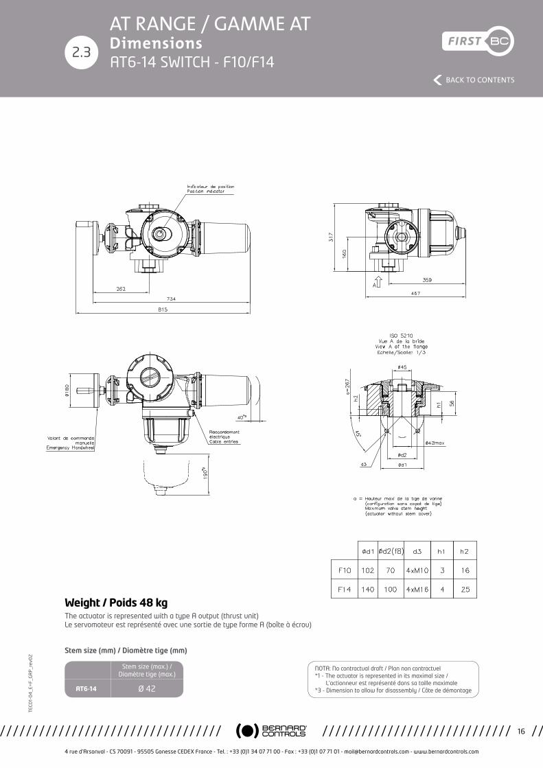
02AT RANGE / GAMME ATDimensions
2.3AT6-14 SWITCH - F10/F14
The actuator is represented with a type A output (thrust unit) Le servomoteur est représenté avec une sortie de type forme A (boîte à écrou)
Weight / Poids 48 kg
Stem size (max.) / Diamètre tige (max.)
AT6-14 Ø 42
Stem size (mm) / Diamètre tige (mm)
NOTA: No contractual draft / Plan non contractuel*1 - The actuator is represented in its maximal size / L’actionneur est représenté dans sa taille maximale*3 - Dimension to allow for disassembly / Côte de démontage
4 rue d’Arsonval - CS 70091 - 95505 Gonesse CEDEX France - Tel. : +33 (0)1 34 07 71 00 - Fax : +33 (0)1 07 71 01 - [email protected] - www.bernardcontrols.com
17
BACK TO CONTENTS
TEC
01-
04
_E+
F_G
RP
_rev
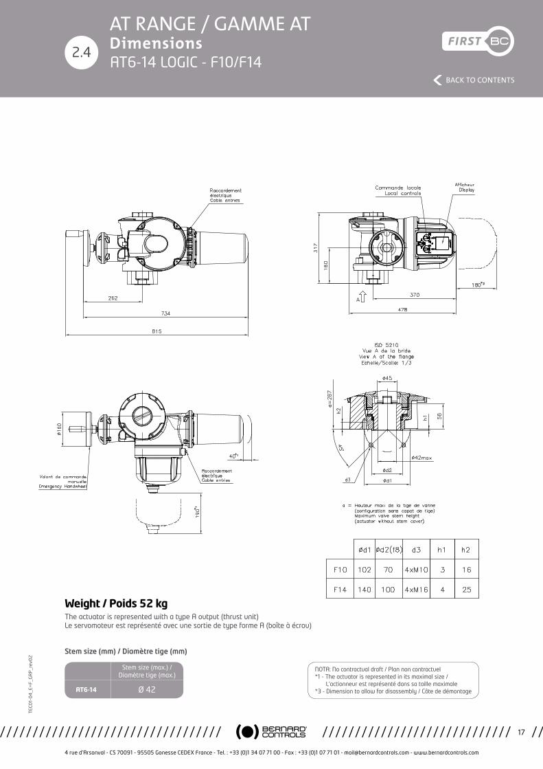
02AT RANGE / GAMME ATDimensions
2.4AT6-14 LOGIC - F10/F14
The actuator is represented with a type A output (thrust unit) Le servomoteur est représenté avec une sortie de type forme A (boîte à écrou)
Weight / Poids 52 kg
Stem size (max.) / Diamètre tige (max.)
AT6-14 Ø 42
Stem size (mm) / Diamètre tige (mm)
NOTA: No contractual draft / Plan non contractuel*1 - The actuator is represented in its maximal size / L’actionneur est représenté dans sa taille maximale*3 - Dimension to allow for disassembly / Côte de démontage

4 rue d’Arsonval - CS 70091 - 95505 Gonesse CEDEX France - Tel. : +33 (0)1 34 07 71 00 - Fax : +33 (0)1 07 71 01 - [email protected] - www.bernardcontrols.com
18
BACK TO CONTENTS
TEC
01-
04
_E+
F_G
RP
_rev
02AT RANGE / GAMME ATDimensions
2.5AT25 SWITCH - F14
The actuator is represented with a type A output (thrust unit) Le servomoteur est représenté avec une sortie de type forme A (boîte à écrou)
Weight / Poids 64 kg
Stem size (max.) / Diamètre tige (max.)
AT25 Ø 60
Stem size (mm) / Diamètre tige (mm)
NOTA: No contractual draft / Plan non contractuel*1 - The actuator is represented in its maximal size / L’actionneur est représenté dans sa taille maximale*3 - Dimension to allow for disassembly / Côte de démontage

4 rue d’Arsonval - CS 70091 - 95505 Gonesse CEDEX France - Tel. : +33 (0)1 34 07 71 00 - Fax : +33 (0)1 07 71 01 - [email protected] - www.bernardcontrols.com
19
BACK TO CONTENTS
TEC
01-
04
_E+
F_G
RP
_rev
02AT RANGE / GAMME ATDimensions
2.6AT25 LOGIC - F14
The actuator is represented with a type A output (thrust unit) Le servomoteur est représenté avec une sortie de type forme A (boîte à écrou)
Weight / Poids 68 kg
Stem size (max.) / Diamètre tige (max.)
AT25 Ø 60
Stem size (mm) / Diamètre tige (mm)
NOTA: No contractual draft / Plan non contractuel*1 - The actuator is represented in its maximal size / L’actionneur est représenté dans sa taille maximale*3 - Dimension to allow for disassembly / Côte de démontage
4 rue d’Arsonval - CS 70091 - 95505 Gonesse CEDEX France - Tel. : +33 (0)1 34 07 71 00 - Fax : +33 (0)1 07 71 01 - [email protected] - www.bernardcontrols.com
20
BACK TO CONTENTS
TEC
01-
04
_E+
F_G
RP
_rev
02AT RANGE / GAMME ATDimensions
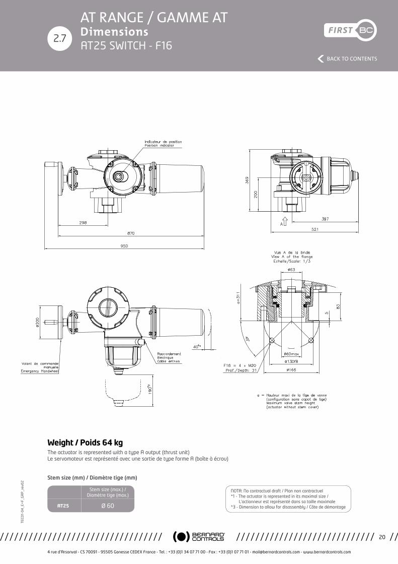
2.7AT25 SWITCH - F16
The actuator is represented with a type A output (thrust unit) Le servomoteur est représenté avec une sortie de type forme A (boîte à écrou)
Weight / Poids 64 kg
Stem size (max.) / Diamètre tige (max.)
AT25 Ø 60
Stem size (mm) / Diamètre tige (mm)
NOTA: No contractual draft / Plan non contractuel*1 - The actuator is represented in its maximal size / L’actionneur est représenté dans sa taille maximale*3 - Dimension to allow for disassembly / Côte de démontage
4 rue d’Arsonval - CS 70091 - 95505 Gonesse CEDEX France - Tel. : +33 (0)1 34 07 71 00 - Fax : +33 (0)1 07 71 01 - [email protected] - www.bernardcontrols.com
21
BACK TO CONTENTS
TEC
01-
04
_E+
F_G
RP
_rev
02AT RANGE / GAMME ATDimensions
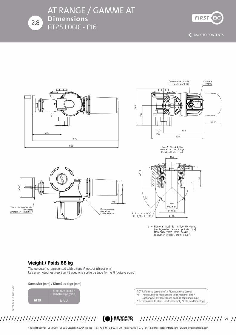
2.8AT25 LOGIC - F16
The actuator is represented with a type A output (thrust unit) Le servomoteur est représenté avec une sortie de type forme A (boîte à écrou)
Weight / Poids 68 kg
Stem size (max.) / Diamètre tige (max.)
AT25 Ø 60
Stem size (mm) / Diamètre tige (mm)
NOTA: No contractual draft / Plan non contractuel*1 - The actuator is represented in its maximal size / L’actionneur est représenté dans sa taille maximale*3 - Dimension to allow for disassembly / Côte de démontage
4 rue d’Arsonval - CS 70091 - 95505 Gonesse CEDEX France - Tel. : +33 (0)1 34 07 71 00 - Fax : +33 (0)1 07 71 01 - [email protected] - www.bernardcontrols.com
22
BACK TO CONTENTS
TEC
01-
04
_E+
F_G
RP
_rev
02AT RANGE / GAMME ATDimensions
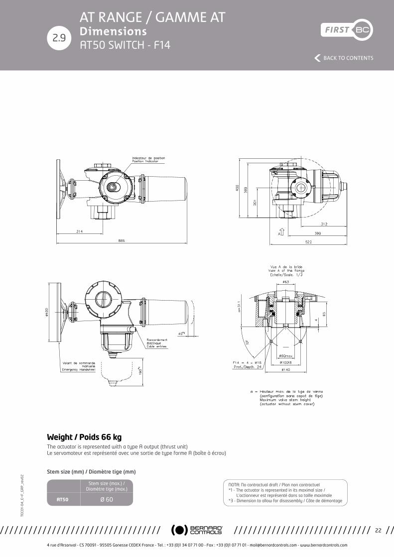
2.9AT50 SWITCH - F14
The actuator is represented with a type A output (thrust unit) Le servomoteur est représenté avec une sortie de type forme A (boîte à écrou)
Weight / Poids 66 kg
Stem size (max.) / Diamètre tige (max.)
AT50 Ø 60
Stem size (mm) / Diamètre tige (mm)
NOTA: No contractual draft / Plan non contractuel*1 - The actuator is represented in its maximal size / L’actionneur est représenté dans sa taille maximale*3 - Dimension to allow for disassembly / Côte de démontage
4 rue d’Arsonval - CS 70091 - 95505 Gonesse CEDEX France - Tel. : +33 (0)1 34 07 71 00 - Fax : +33 (0)1 07 71 01 - [email protected] - www.bernardcontrols.com
23
BACK TO CONTENTS
TEC
01-
04
_E+
F_G
RP
_rev
02AT RANGE / GAMME ATDimensions
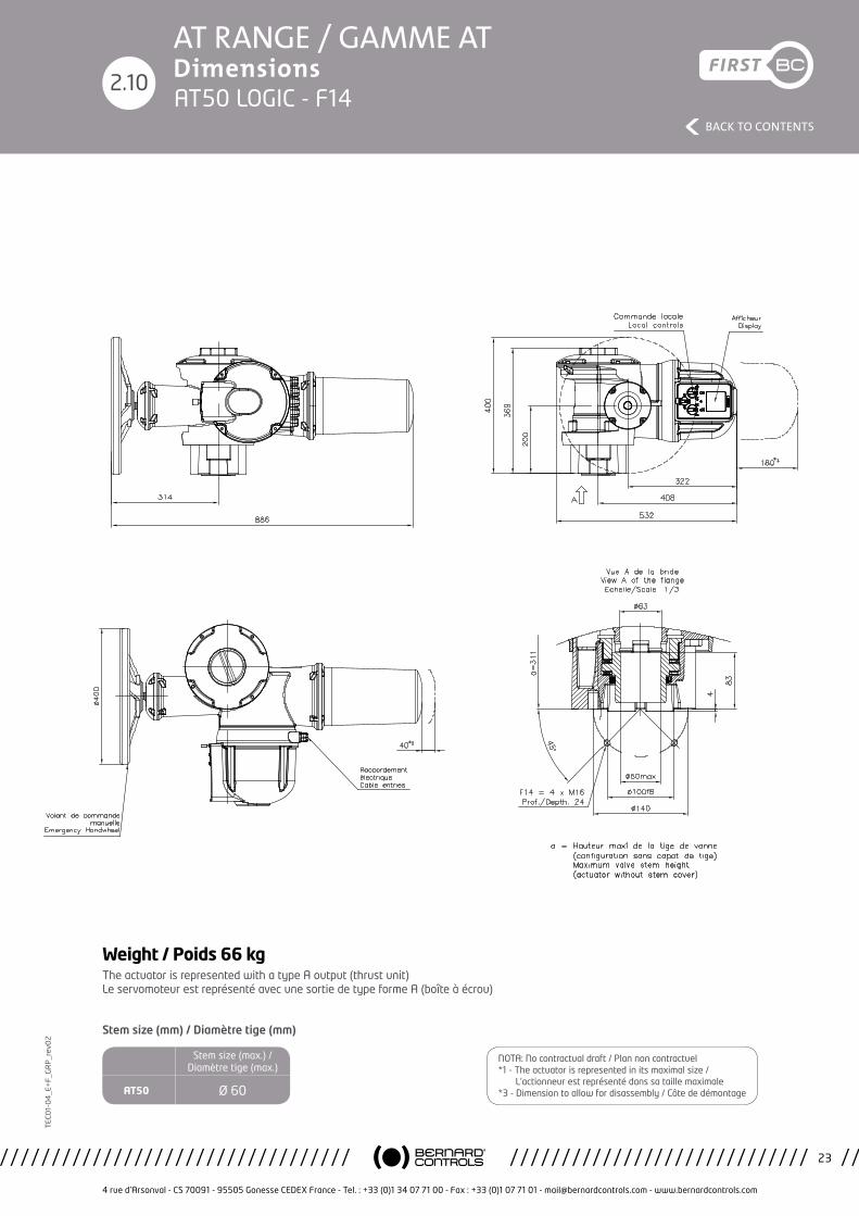
2.10AT50 LOGIC - F14
The actuator is represented with a type A output (thrust unit) Le servomoteur est représenté avec une sortie de type forme A (boîte à écrou)
Weight / Poids 66 kg
Stem size (max.) / Diamètre tige (max.)
AT50 Ø 60
Stem size (mm) / Diamètre tige (mm)
NOTA: No contractual draft / Plan non contractuel*1 - The actuator is represented in its maximal size / L’actionneur est représenté dans sa taille maximale*3 - Dimension to allow for disassembly / Côte de démontage
4 rue d’Arsonval - CS 70091 - 95505 Gonesse CEDEX France - Tel. : +33 (0)1 34 07 71 00 - Fax : +33 (0)1 07 71 01 - [email protected] - www.bernardcontrols.com
24
BACK TO CONTENTS
TEC
01-
04
_E+
F_G
RP
_rev
02AT RANGE / GAMME ATDimensions
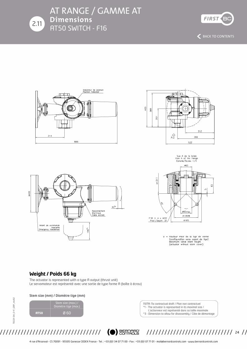
2.11AT50 SWITCH - F16
The actuator is represented with a type A output (thrust unit) Le servomoteur est représenté avec une sortie de type forme A (boîte à écrou)
Weight / Poids 66 kg
Stem size (max.) / Diamètre tige (max.)
AT50 Ø 60
Stem size (mm) / Diamètre tige (mm)
NOTA: No contractual draft / Plan non contractuel*1 - The actuator is represented in its maximal size / L’actionneur est représenté dans sa taille maximale*3 - Dimension to allow for disassembly / Côte de démontage
4 rue d’Arsonval - CS 70091 - 95505 Gonesse CEDEX France - Tel. : +33 (0)1 34 07 71 00 - Fax : +33 (0)1 07 71 01 - [email protected] - www.bernardcontrols.com
25
BACK TO CONTENTS
TEC
01-
04
_E+
F_G
RP
_rev
02AT RANGE / GAMME ATDimensions
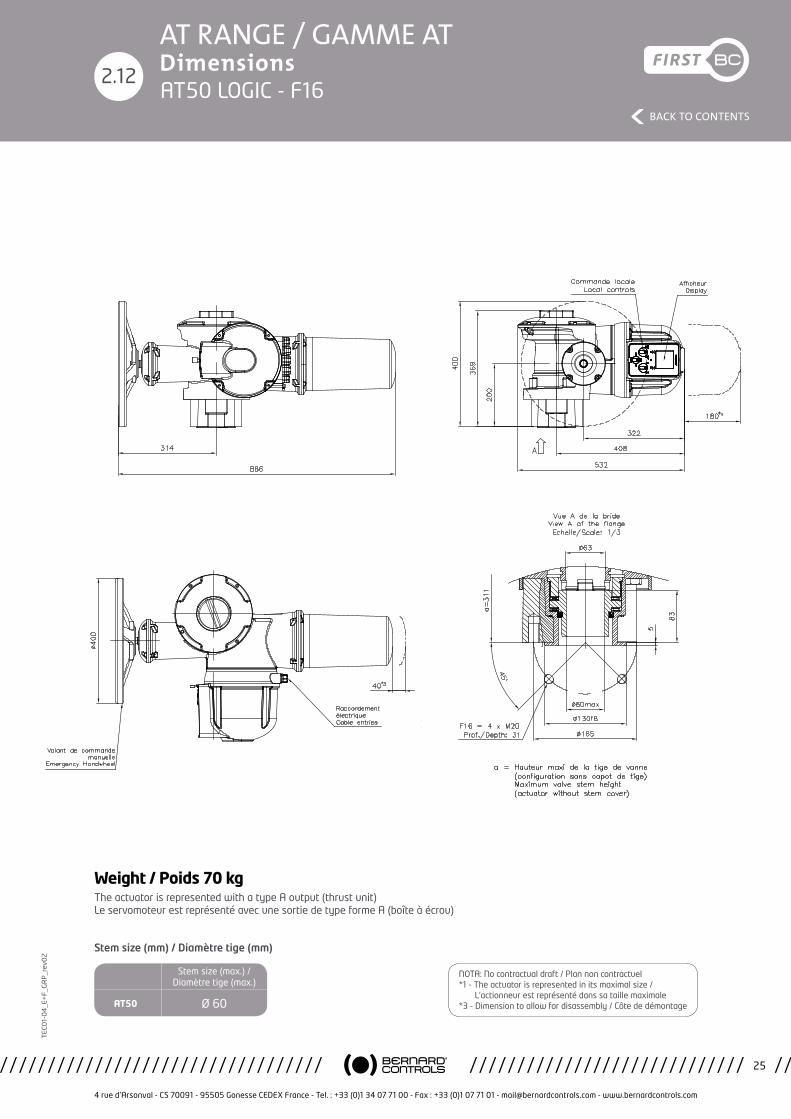
2.12AT50 LOGIC - F16
The actuator is represented with a type A output (thrust unit) Le servomoteur est représenté avec une sortie de type forme A (boîte à écrou)
Weight / Poids 70 kg
Stem size (max.) / Diamètre tige (max.)
AT50 Ø 60
Stem size (mm) / Diamètre tige (mm)
NOTA: No contractual draft / Plan non contractuel*1 - The actuator is represented in its maximal size / L’actionneur est représenté dans sa taille maximale*3 - Dimension to allow for disassembly / Côte de démontage
4 rue d’Arsonval - CS 70091 - 95505 Gonesse CEDEX France - Tel. : +33 (0)1 34 07 71 00 - Fax : +33 (0)1 07 71 01 - [email protected] - www.bernardcontrols.com
26
BACK TO CONTENTS
TEC
01-
04
_E+
F_G
RP
_rev
02AT RANGE / GAMME ATDimensions
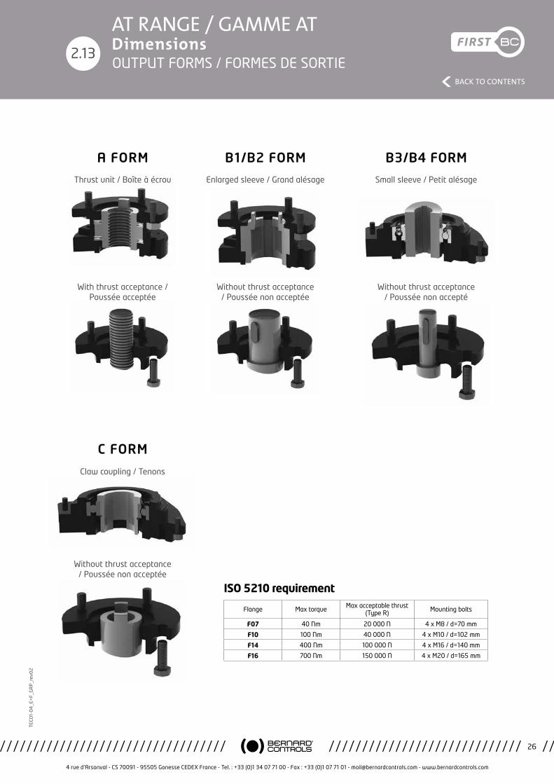
2.13OUTPUT FORMS / FORMES DE SORTIE
ISO 5210 requirement
Flange Max torque Max acceptable thrust (Type R) Mounting bolts
F07 40 Nm 20 000 N 4 x M8 / d=70 mm
F10 100 Nm 40 000 N 4 x M10 / d=102 mm
F14 400 Nm 100 000 N 4 x M16 / d=140 mm
F16 700 Nm 150 000 N 4 x M20 / d=165 mm
A FORM
C FORM
B1/B2 FORM B3/B4 FORM
Thrust unit / Boîte à écrou
With thrust acceptance / Poussée acceptée
Without thrust acceptance / Poussée non acceptée
Claw coupling / Tenons
Enlarged sleeve / Grand alésage
Without thrust acceptance / Poussée non acceptée
Without thrust acceptance / Poussée non accepté
Small sleeve / Petit alésage
4 rue d’Arsonval - CS 70091 - 95505 Gonesse CEDEX France - Tel. : +33 (0)1 34 07 71 00 - Fax : +33 (0)1 07 71 01 - [email protected] - www.bernardcontrols.com
27
BACK TO CONTENTS
TEC
01-
04
_E+
F_G
RP
_rev
02
*AT RANGE / GAMME AT Wiring / Câblage
Etude/Study:
Ind./Rev.:PRO D
Pla nche/Sheet:
Projet/Projec t: M od ific a tion:
A pprouvé/Approved A pprouvé/ApprovedDessiné pa r:Desig ned by:
Vérifié pa r:C hec ked by:
Va lidé pa r:Va lida ted by: PRO TO
C e pla n éta nt notre prop riété, il ne peut être reproduit ou c ommuniqué sa ns notre a utorisa tion éc rite.This d ra wing is our property a nd ma y no t be reproduced or c ommunic a ted without our written a utho riza tion.
4 rue d 'A rsonva l BP 9195505 G O NESSE C EDEX
www.berna rdc ontro ls.com
15M 24
D
1PH/3PH AT/AQ -25-30-50 STANDARD
DM _17369
AT/AQ -25-30-50 1PH/3PH STANDARD
WD_500036_FREN
Potentiomètre, Tra nsmetteur de position
Potentiometer, Position tra nsmitter
17/11/17
D.Sc hwebel
17/11/17 17/11/17
F.Ha n
17/11/17 ->->G .Hou RG uilla ume
STA NDARD
M
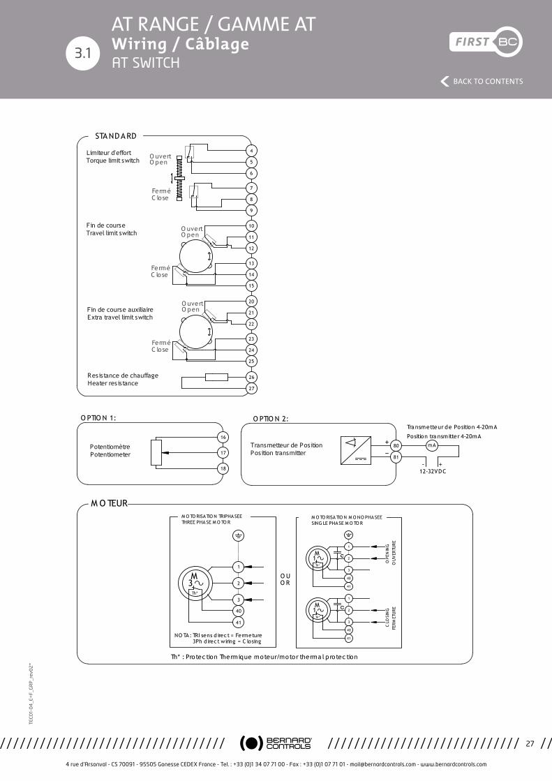
NO TA: TRI sens d irec t = Fermeture
3
M O TO RISATIO N TRIPHA SEETHREE PHA SE M O TO R
O U
Th* : Protec tion Thermique moteur/motor therma l protec tion
M O TEUR
Th*
3Ph d irec t wiring = C losing
12-32VDC-
mA
O PTIO N 2:
+
O PTIO N 1:
16
17
18
80
81
21
20
22
24
23
25
11
10
12
14
13
15
26
27
1
2
3
40
41
O R
5
4
6
8
7
9
M O TO RISA TIO N M O NO PHA SEESING LE PHASE M O TO R
M1
Th*
1
2
3
40
41
OPE
NIN
G
M1
Th*
1
2
3
40
41
CLO
SIN
GO
UV
ERTU
RE
FERM
ETU
RE
Tra nsmetteur de Position 4-20mA
Position tra nsmitter 4-20mA
Transmetteur de PositionPosition transmitter
PotentiomètrePotentiometer
Limiteur d'effortTorque limit switch
Fin de course Travel limit switch
O uvertO pen
FerméC lose
O uvertO pen
FerméC lose
O uvertO pen
FerméC lose
Fin de course auxiliaireExtra travel limit switch
Resistance de chauffageHeater resistance
3.1AT SWITCH
4 rue d’Arsonval - CS 70091 - 95505 Gonesse CEDEX France - Tel. : +33 (0)1 34 07 71 00 - Fax : +33 (0)1 07 71 01 - [email protected] - www.bernardcontrols.com
28
BACK TO CONTENTS
TEC
01-
04
_E+
F_G
RP
_rev
02
*AT RANGE / GAMME AT Wiring / Câblage
3.2
Emer
genc
y Su
pply
24V
Etud
e/St
udy:
Ind.
/Rev
.:PR
OD
Plan
che/
Shee
t:
Proj
et/P
roje
ct:
Mod
ific
atio
n:
Appr
ouvé
/App
rove
dAp
prou
vé/A
ppro
ved
Dess
iné
par:
Desi
gned
by:
Véri
fié
par:
Chec
ked
by:
Valid
é pa
r:Va
lidat
ed b
y:PR
OTO
Ce p
lan
étan
t no
tre
prop
riété
, il n
e pe
ut ê
tre
repr
odui
t ou
com
mun
iqué
san
s no
tre
auto
risat
ion
écrit
e.Th
is dr
awin
g is
our p
rope
rty
and
may
not
be
repr
oduc
ed o
r com
mun
icat
ed w
ithou
t ou
r writ
ten
auth
oriz
atio
n.
4 ru
e d'
Arso
nval
BP
91
9550
5 G
ON
ESSE
CED
EX
ww
w.b
erna
rdco
ntro
ls.c
om
PBCD
T160
10
B
DM17
253
AT/A
Q-2
5 à
50
MO
NO
PHAS
EE
LOG
IC
SIN
GLE
PH
ASE
AT/A
Q-2
5 to
50
LOG
IC
WD_
6300
59_F
REN
Rési
stan
ce
Hea
ter
10/0
8/17
L.M
aiss
in
08/0
8/17
10/0
8/17
Mon
tagn
er
10/0
8/17
->->A.
Dela
nnes
D.Sc
hweb
el
9
10
11
Lége
nde
/ Le
gend
CAux1
CO
6
7
8
3
4
5
10 à
60V
S
Conn
ecti
on f
or c
ontr
ol b
y vo
ltag
e Ra
ccor
dem
ents
pou
r cd
e pa
r te
nsio
n
90 à
250
V
Not
e:
SOAux2
To c
ance
l sel
f ho
ldin
g cm
d Do
no
t co
nnec
t te
rmin
al 7
Pour
sup
prim
er l'
auto
mai
ntie
n ne
pas
rac
cord
er la
bor
ne 7
TH
Conn
ecti
on f
or c
ontr
ol b
y co
ntac
t Ra
ccor
dem
ents
pou
r cd
e pa
r co
ntac
t
CO
S
2827
4 3 2 19 8 7
SIGNALLING
R1R3 R2RD
1
P11 6 5
2625
2423
2221
20
LOCAL CONTROL
8 9 10 113 4 5
REMOTE COMMANDS
P13 6 7
34
56
78
910
11
1 2 3 4 5 6
1 21
2
321
COIL
3 4 51 2J2Ca
pteu
r de
Cou
ple
Capt
eur
de P
osit
ion
Torq
ue S
enso
r
Posi
tion
sen
sor
11
10
9
8
7
6
5
4
3
P7 P51 2TH
P6
65
43
21
19V
23V
L Ph
Cont
rol b
y vo
ltag
e
Out
put
Supp
ly 2
4V
Cont
rol b
y Co
ntac
t
Loca
l Inh
ibit
ion
& E
SD
CI28
02
-
-
+
+
4
DD
R2R1
12Em
erge
ncy
supp
ly in
put
RDR3
+En
trée
alim
enta
tion
de
seco
urs
-
Cust
omer
Con
figu
rati
on
Conf
igur
atio
n Cl
ient
POSITION &
TORQUE
U X 1AA U X 2
U X 1AA U X 2
Valv
e cl
osed
Vann
e fe
rmée
Valv
e op
enVa
nne
ouve
rte
Conf
igur
able
rel
ay R
elai
s co
nfig
urab
le
Faul
t re
lay
term
inal
26-
28 c
lose
d=
actu
ator
ava
ilabl
eRe
lais
déf
aut
cont
act
26-2
8 fe
rmé=
se
rvom
oteu
r di
spon
ible
Conf
igur
able
com
man
d Co
mm
ande
con
figu
rabl
e
Conf
igur
able
com
man
d Co
mm
ande
con
figu
rabl
e
Clos
ing
com
man
d Co
mm
ande
fer
met
ure
Ope
ning
com
man
d Co
mm
ande
ouv
ertu
re
Stop
Ther
mal
pro
tect
ion
Prot
ecti
on t
herm
ique
13 2
M1
C2A1
A2
C1A1
A2
L2/N
L3L1
Tran
sfor
mer
Bo
ard
19V
23V
L Ph
PE
L1/N
L2/L
Hea
ter
Chau
ffag
e
DISP
LAY
see customer configuration / voir configuration client
Mot
or /
Mot
eur
Cust
omer
Ter
min
als
/
Bor
nes
clie
ntAT LOGIC Single-phase AT LOGIC Mono-phasé
4 rue d’Arsonval - CS 70091 - 95505 Gonesse CEDEX France - Tel. : +33 (0)1 34 07 71 00 - Fax : +33 (0)1 07 71 01 - [email protected] - www.bernardcontrols.com
29
BACK TO CONTENTS
TEC
01-
04
_E+
F_G
RP
_rev
02
*AT RANGE / GAMME AT Wiring / Câblage
3.3
Emer
genc
y Su
pply
24V
Etud
e/St
udy:
Ind.
/Rev
.:PR
OD
Plan
che/
Shee
t:
Proj
et/P
roje
ct:
Mod
ific
atio
n:
Appr
ouvé
/App
rove
dAp
prou
vé/A
ppro
ved
Dess
iné
par:
Desi
gned
by:
Véri
fié
par:
Chec
ked
by:
Valid
é pa
r:Va
lidat
ed b
y:PR
OTO
Ce p
lan
étan
t no
tre
prop
riété
, il n
e pe
ut ê
tre
repr
odui
t ou
com
mun
iqué
san
s no
tre
auto
risat
ion
écrit
e.Th
is dr
awin
g is
our p
rope
rty
and
may
not
be
repr
oduc
ed o
r com
mun
icat
ed w
ithou
t ou
r writ
ten
auth
oriz
atio
n.
4 ru
e d'
Arso
nval
BP
91
9550
5 G
ON
ESSE
CED
EX
ww
w.b
erna
rdco
ntro
ls.c
om
PBCD
T160
10
D
DM17
374
AT/A
Q-2
5 à
50
MO
NO
PHAS
EE
LOG
IC
SIN
GLE
PH
ASE
AT/A
Q-2
5 to
50
LOG
IC
WD_
6300
34_F
REN
On/
Off
On/
Off
18/1
2/17
L.M
aiss
in
05/1
2/17
Mon
tagn
er
05/1
2/17
->->M
.Wol
osz
S.Da
dier
21
/12/
17
9
10
11
Lége
nde
/ Le
gend
CAux1
CO
6
7
8
3
4
5
10 à
60V
S
Conn
ecti
on f
or c
ontr
ol b
y vo
ltag
e Ra
ccor
dem
ents
pou
r cd
e pa
r te
nsio
n
90 à
250
V
Not
e:
SOAux2
To c
ance
l se
lf h
oldi
ng c
md
Do
not
conn
ect
term
inal
7Po
ur s
uppr
imer
l'au
tom
aint
ien
ne p
as r
acco
rder
la b
orne
7
TH
Conn
ecti
on f
or c
ontr
ol b
y co
ntac
t Ra
ccor
dem
ents
pou
r cd
e pa
r co
ntac
t
CO
S
2827
4 3 2 19 8 7
SIGNALLING
R1R3 R2RD
1
P11 6 5
2625
2423
2221
20
LOCAL CONTROL
8 9 10 113 4 5
REMOTE COMMANDS
P13 6 7
34
56
78
910
11
1 2 3 4 5 6
1 21
2
321
COIL
3 4 51 2J2Ca
pteu
r de
Cou
ple
Capt
eur
de P
osit
ion
Torq
ue S
enso
r
Posi
tion
sen
sor
11
10
9
8
7
6
5
4
3
P7 P51 2TH
P6
65
43
21
19V
23V
L Ph
Cont
rol b
y vo
ltag
e
Out
put
Supp
ly 2
4V
Cont
rol b
y Co
ntac
t
Aux
1 &
Aux
2
CI28
02
-
-
+
+
4
DD
R2R1
12Em
erge
ncy
supp
ly in
put
RDR3
+En
trée
alim
enta
tion
de
seco
urs
-
Cust
omer
Con
figu
rati
on
Conf
igur
atio
n Cl
ient
POSITION &
TORQUE
U X 1AA U X 2
U X 1AA U X 2
Conf
igur
able
com
man
d Co
mm
ande
con
figu
rabl
e
Conf
igur
able
com
man
d Co
mm
ande
con
figu
rabl
e
Clos
ing
com
man
d Co
mm
ande
fer
met
ure
Ope
ning
com
man
d Co
mm
ande
ouv
ertu
re
Stop
Ther
mal
pro
tect
ion
Prot
ecti
on t
herm
ique
13 2
M1
C2A1
A2
C1A1
A2
L2/L
L3L1
/N
Tran
sfor
mer
Bo
ard
19V
23V
L Ph
PE
L1/N
L2/L
DISP
LAY
Hea
ter
Chau
ffag
e
Valv
e op
enVa
nne
ouve
rte
Valv
e cl
osed
Vann
e fe
rmée
Conf
igur
able
rel
ay R
elai
s co
nfig
urab
le
Faul
t re
lay
term
inal
26-
28 c
lose
d=
actu
ator
ava
ilabl
eRe
lais
déf
aut
cont
act
26-2
8 fe
rmé=
se
rvom
oteu
r di
spon
ible
see customer configuration / voir configuration client
Mot
or /
Mot
eur
Cust
omer
Ter
min
als
/
Bor
nes
clie
ntAT LOGIC Single-phase - On-Off AT LOGIC Mono-phasé - Tout ou Rien
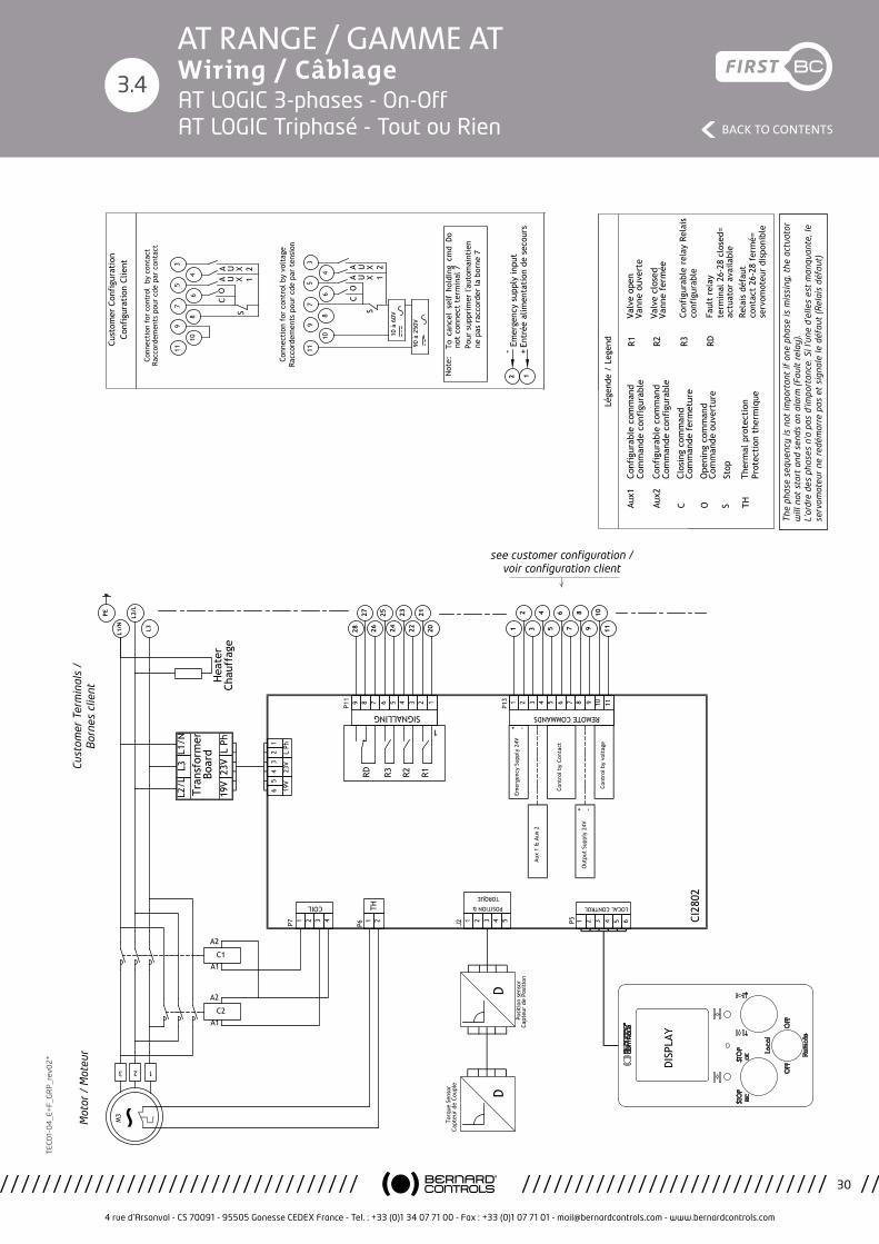
4 rue d’Arsonval - CS 70091 - 95505 Gonesse CEDEX France - Tel. : +33 (0)1 34 07 71 00 - Fax : +33 (0)1 07 71 01 - [email protected] - www.bernardcontrols.com
30
BACK TO CONTENTS
TEC
01-
04
_E+
F_G
RP
_rev
02
*AT RANGE / GAMME AT Wiring / Câblage
3.4
Emer
genc
y Su
pply
24V
Etud
e/St
udy:
Ind.
/Rev
.:PR
OD
Plan
che/
Shee
t:
Proj
et/P
roje
ct:
Mod
ific
atio
n:
Appr
ouvé
/App
rove
dAp
prou
vé/A
ppro
ved
Dess
iné
par:
Desi
gned
by:
Véri
fié
par:
Chec
ked
by:
Valid
é pa
r:Va
lidat
ed b
y:PR
OTO
Ce p
lan
étan
t no
tre
prop
riété
, il n
e pe
ut ê
tre
repr
odui
t ou
com
mun
iqué
san
s no
tre
auto
risat
ion
écrit
e.Th
is dr
awin
g is
our p
rope
rty
and
may
not
be
repr
oduc
ed o
r com
mun
icat
ed w
ithou
t ou
r writ
ten
auth
oriz
atio
n.
4 ru
e d'
Arso
nval
BP
91
9550
5 G
ON
ESSE
CED
EX
ww
w.b
erna
rdco
ntro
ls.c
om
PBCD
T160
10
E
DM17
374
AT/A
Q-2
5 à
50 T
RIPH
ASEE
LO
GIC
TH
REE
PHAS
E AT
/AQ
-25
to 5
0 LO
GIC
WD_
6300
35_F
REN
On/
Off
On/
Off
18/1
2/17
L.M
aiss
in
05/1
2/17
Mon
tagn
er
05/1
2/17
->->M
.Wol
osz
S.Da
dier
21
/12/
17
9
10
11
Lége
nde
/ Le
gend
CAux1
CO
6
7
8
3
4
5
10 à
60V
S
Conn
ecti
on f
or c
ontr
ol b
y vo
ltag
e Ra
ccor
dem
ents
pou
r cd
e pa
r te
nsio
n
90 à
250
V
Not
e:
SOAux2
To c
ance
l se
lf h
oldi
ng c
md
Do
not
conn
ect
term
inal
7Po
ur s
uppr
imer
l'au
tom
aint
ien
ne p
as r
acco
rder
la b
orne
7
TH
Conn
ecti
on f
or c
ontr
ol b
y co
ntac
t Ra
ccor
dem
ents
pou
r cd
e pa
r co
ntac
t
CO
S
2827
4 3 2 19 8 7
SIGNALLING
R1R3 R2RD
1
P11 6 5
2625
2423
2221
20
LOCAL CONTROL
8 9 10 113 4 5
REMOTE COMMANDS
P13 6 7
34
56
78
910
11
1 2 3 4 5 6
1 21
2
321
COIL
3 4 51 2J2Ca
pteu
r de
Cou
ple
Capt
eur
de P
osit
ion
Torq
ue S
enso
r
Posi
tion
sen
sor
11
10
9
8
7
6
5
4
3
P7 P51 2TH
P6
65
43
21
19V
23V
L Ph
Cont
rol b
y vo
ltag
e
Out
put
Supp
ly 2
4V
Cont
rol b
y Co
ntac
t
Aux
1 &
Aux
2
CI28
02
-
-
+
+
4
DD
R2R1
12Em
erge
ncy
supp
ly in
put
RDR3
+En
trée
alim
enta
tion
de
seco
urs
-
Cust
omer
Con
figu
rati
on
Conf
igur
atio
n Cl
ient
POSITION &
TORQUE
U X 1AA U X 2
U X 1AA U X 2
Conf
igur
able
com
man
d Co
mm
ande
con
figu
rabl
e
Conf
igur
able
com
man
d Co
mm
ande
con
figu
rabl
e
Clos
ing
com
man
d Co
mm
ande
fer
met
ure
Ope
ning
com
man
d Co
mm
ande
ouv
ertu
re
Stop
Ther
mal
pro
tect
ion
Prot
ecti
on t
herm
ique
L2/L
L3L1
/N
Tran
sfor
mer
Bo
ard
19V
23V
L Ph
13 2
M3
C2A1
A2
C1A1
A2
The
phas
e se
quen
cy is
not
impo
rtan
t If
one
pha
se is
mis
sing
, th
e ac
tuat
or w
ill n
ot s
tart
and
se
nds
an a
larm
(Fa
ult
rela
y).
L'or
dre
des
phas
es n
'a p
as d
'impo
rtan
ce.
Si l'
une
d'el
les
est
man
quan
te,
le s
ervo
mot
eur
ne
redé
mar
re p
as e
t si
gnal
e le
déf
aut
(Rel
ais
défa
ut).
PE
L1/N
L2/L
L3
DISP
LAY
Hea
ter
Chau
ffag
e
Valv
e op
enVa
nne
ouve
rte
Valv
e cl
osed
Vann
e fe
rmée
Conf
igur
able
rel
ay R
elai
s co
nfig
urab
le
Faul
t re
lay
term
inal
26-
28 c
lose
d=
actu
ator
ava
ilabl
eRe
lais
déf
aut
cont
act
26-2
8 fe
rmé=
se
rvom
oteu
r di
spon
ible
see customer configuration / voir configuration client
Mot
or /
Mot
eur
Cust
omer
Ter
min
als
/
Bor
nes
clie
nt
The
pha
se s
eque
ncy
is n
ot im
port
ant
if o
ne p
hase
is m
issi
ng, t
he a
ctua
tor
will
not
sta
rt a
nd s
ends
an
alar
m (
Faul
t re
lay)
. L’
ordr
e de
s ph
ases
n’a
pas
d’im
port
ance
. Si l
’une
d’e
lles
est
man
quan
te, l
e se
rvom
oteu
r ne
red
émar
re p
as e
t si
gnal
e le
déf
aut
(Rel
ais
défa
ut)
AT LOGIC 3-phases - On-Off AT LOGIC Triphasé - Tout ou Rien
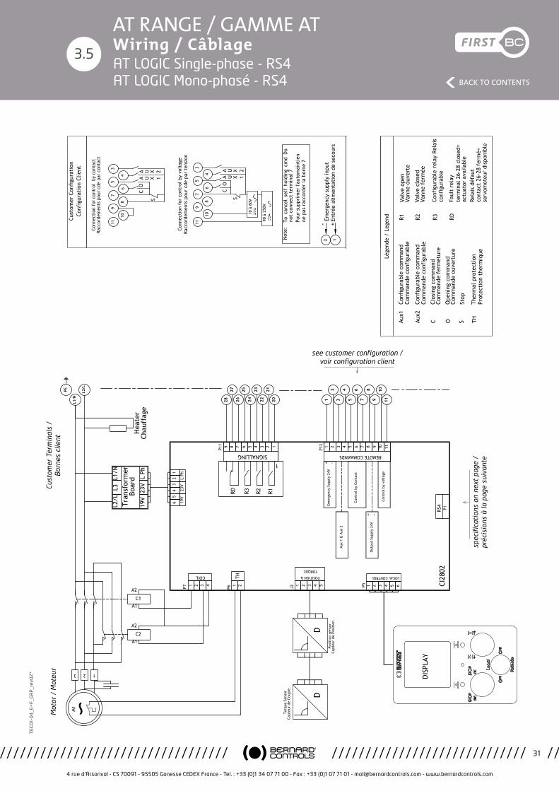
4 rue d’Arsonval - CS 70091 - 95505 Gonesse CEDEX France - Tel. : +33 (0)1 34 07 71 00 - Fax : +33 (0)1 07 71 01 - [email protected] - www.bernardcontrols.com
31
BACK TO CONTENTS
TEC
01-
04
_E+
F_G
RP
_rev
02
*AT RANGE / GAMME AT Wiring / Câblage
3.5
Emer
genc
y Su
pply
24V
Etud
e/St
udy:
Ind.
/Rev
.:PR
OD
Plan
che/
Shee
t:
Proj
et/P
roje
ct:
Mod
ific
atio
n:
Appr
ouvé
/App
rove
dAp
prou
vé/A
ppro
ved
Dess
iné
par:
Desi
gned
by:
Véri
fié
par:
Chec
ked
by:
Valid
é pa
r:Va
lidat
ed b
y:PR
OTO
Ce p
lan
étan
t no
tre
prop
riété
, il n
e pe
ut ê
tre
repr
odui
t ou
com
mun
iqué
san
s no
tre
auto
risat
ion
écrit
e.Th
is dr
awin
g is
our p
rope
rty
and
may
not
be
repr
oduc
ed o
r com
mun
icat
ed w
ithou
t ou
r writ
ten
auth
oriz
atio
n.
4 ru
e d'
Arso
nval
BP
91
9550
5 G
ON
ESSE
CED
EX
ww
w.b
erna
rdco
ntro
ls.c
om
PBCD
T160
10
D
DM17
374
AT/A
Q-2
5 à
50
MO
NO
PHAS
EE
LOG
IC
SIN
GLE
PH
ASE
AT/A
Q-2
5 to
50
LOG
IC
WD_
6300
28_F
REN
RS4
RS4
18/1
2/17
L.M
aiss
in
05/1
2/17
Mon
tagn
er
05/1
2/17
->->M
.Wol
osz
S.Da
dier
21
/12/
17
9
10
11
Lége
nde
/ Le
gend
CAux1
CO
6
7
8
3
4
5
10 à
60V
S
Conn
ecti
on f
or c
ontr
ol b
y vo
ltag
e Ra
ccor
dem
ents
pou
r cd
e pa
r te
nsio
n
90 à
250
V
Not
e:
SOAux2
To c
ance
l se
lf h
oldi
ng c
md
Do
not
conn
ect
term
inal
7Po
ur s
uppr
imer
l'au
tom
aint
ien
ne p
as r
acco
rder
la b
orne
7
TH
Conn
ecti
on f
or c
ontr
ol b
y co
ntac
t Ra
ccor
dem
ents
pou
r cd
e pa
r co
ntac
t
CO
S
2827
4 3 2 19 8 7
SIGNALLING
R1R3 R2RD
1
P11 6 5
2625
2423
2221
20
LOCAL CONTROL
8 9 10 113 4 5
REMOTE COMMANDS
P13 6 7
34
56
78
910
11
1 2 3 4 5 6
1 21
2
321
COIL
3 4 51 2J2Ca
pteu
r de
Cou
ple
Capt
eur
de P
osit
ion
Torq
ue S
enso
r
Posi
tion
sen
sor
11
10
9
8
7
6
5
4
3
P7 P51 2TH
P6
65
43
21
19V
23V
L Ph
Cont
rol b
y vo
ltag
e
Out
put
Supp
ly 2
4V
Cont
rol b
y Co
ntac
t
Aux
1 &
Aux
2
CI28
02
-
-
+
+
RS4
P1
4
DD
R2R1
12Em
erge
ncy
supp
ly in
put
RDR3
+En
trée
alim
enta
tion
de
seco
urs
-
Cust
omer
Con
figu
rati
on
Conf
igur
atio
n Cl
ient
POSITION &
TORQUE
U X 1AA U X 2
U X 1AA U X 2
Conf
igur
able
com
man
d Co
mm
ande
con
figu
rabl
e
Conf
igur
able
com
man
d Co
mm
ande
con
figu
rabl
e
Clos
ing
com
man
d Co
mm
ande
fer
met
ure
Ope
ning
com
man
d Co
mm
ande
ouv
ertu
re
Stop
Ther
mal
pro
tect
ion
Prot
ecti
on t
herm
ique
13 2
M1
C2A1
A2
C1A1
A2
L2/L
L3L1
/N
Tran
sfor
mer
Bo
ard
19V
23V
L Ph
PE
L1/N
L2/L
DISP
LAY
Hea
ter
Chau
ffag
e
Valv
e op
enVa
nne
ouve
rte
Valv
e cl
osed
Vann
e fe
rmée
Conf
igur
able
rel
ay R
elai
s co
nfig
urab
le
Faul
t re
lay
term
inal
26-
28 c
lose
d=
actu
ator
ava
ilabl
eRe
lais
déf
aut
cont
act
26-2
8 fe
rmé=
se
rvom
oteu
r di
spon
ible
spec
ifica
tion
s on
nex
t pa
ge /
pr
écis
ions
à la
pag
e su
ivan
te
see customer configuration / voir configuration client
Mot
or /
Mot
eur
Cust
omer
Ter
min
als
/
Bor
nes
clie
nt
Emer
genc
y Su
pply
24V
Etud
e/St
udy:
Ind.
/Rev
.:PR
OD
Plan
che/
Shee
t:
Proj
et/P
roje
ct:
Mod
ific
atio
n:
Appr
ouvé
/App
rove
dAp
prou
vé/A
ppro
ved
Dess
iné
par:
Desi
gned
by:
Véri
fié
par:
Chec
ked
by:
Valid
é pa
r:Va
lidat
ed b
y:PR
OTO
Ce p
lan
étan
t no
tre
prop
riété
, il n
e pe
ut ê
tre
repr
odui
t ou
com
mun
iqué
san
s no
tre
auto
risat
ion
écrit
e.Th
is dr
awin
g is
our p
rope
rty
and
may
not
be
repr
oduc
ed o
r com
mun
icat
ed w
ithou
t ou
r writ
ten
auth
oriz
atio
n.
4 ru
e d'
Arso
nval
BP
91
9550
5 G
ON
ESSE
CED
EX
ww
w.b
erna
rdco
ntro
ls.c
om
PBCD
T160
10
D
DM17
374
AT/A
Q-2
5 à
50
MO
NO
PHAS
EE
LOG
IC
SIN
GLE
PH
ASE
AT/A
Q-2
5 to
50
LOG
IC
WD_
6300
28_F
REN
RS4
RS4
18/1
2/17
L.M
aiss
in
05/1
2/17
Mon
tagn
er
05/1
2/17
->->M
.Wol
osz
S.Da
dier
21
/12/
17
9
10
11
Lége
nde
/ Le
gend
CAux1
CO
6
7
8
3
4
5
10 à
60V
S
Conn
ecti
on f
or c
ontr
ol b
y vo
ltag
e Ra
ccor
dem
ents
pou
r cd
e pa
r te
nsio
n
90 à
250
V
Not
e:
SOAux2
To c
ance
l se
lf h
oldi
ng c
md
Do
not
conn
ect
term
inal
7Po
ur s
uppr
imer
l'au
tom
aint
ien
ne p
as r
acco
rder
la b
orne
7
TH
Conn
ecti
on f
or c
ontr
ol b
y co
ntac
t Ra
ccor
dem
ents
pou
r cd
e pa
r co
ntac
t
CO
S
2827
4 3 2 19 8 7
SIGNALLING
R1R3 R2RD
1
P11 6 5
2625
2423
2221
20
LOCAL CONTROL
8 9 10 113 4 5
REMOTE COMMANDS
P13 6 7
34
56
78
910
11
1 2 3 4 5 6
1 21
2
321
COIL
3 4 51 2J2Ca
pteu
r de
Cou
ple
Capt
eur
de P
osit
ion
Torq
ue S
enso
r
Posi
tion
sen
sor
11
10
9
8
7
6
5
4
3
P7 P51 2TH
P6
65
43
21
19V
23V
L Ph
Cont
rol b
y vo
ltag
e
Out
put
Supp
ly 2
4V
Cont
rol b
y Co
ntac
t
Aux
1 &
Aux
2
CI28
02
-
-
+
+
RS4
P1
4
DD
R2R1
12Em
erge
ncy
supp
ly in
put
RDR3
+En
trée
alim
enta
tion
de
seco
urs
-
Cust
omer
Con
figu
rati
on
Conf
igur
atio
n Cl
ient
POSITION &
TORQUE
U X 1AA U X 2
U X 1AA U X 2
Conf
igur
able
com
man
d Co
mm
ande
con
figu
rabl
e
Conf
igur
able
com
man
d Co
mm
ande
con
figu
rabl
e
Clos
ing
com
man
d Co
mm
ande
fer
met
ure
Ope
ning
com
man
d Co
mm
ande
ouv
ertu
re
Stop
Ther
mal
pro
tect
ion
Prot
ecti
on t
herm
ique
13 2
M1
C2A1
A2
C1A1
A2
L2/L
L3L1
/N
Tran
sfor
mer
Bo
ard
19V
23V
L Ph
PE
L1/N
L2/L
DISP
LAY
Hea
ter
Chau
ffag
e
Valv
e op
enVa
nne
ouve
rte
Valv
e cl
osed
Vann
e fe
rmée
Conf
igur
able
rel
ay R
elai
s co
nfig
urab
le
Faul
t re
lay
term
inal
26-
28 c
lose
d=
actu
ator
ava
ilabl
eRe
lais
déf
aut
cont
act
26-2
8 fe
rmé=
se
rvom
oteu
r di
spon
ible
AT LOGIC Single-phase - RS4 AT LOGIC Mono-phasé - RS4
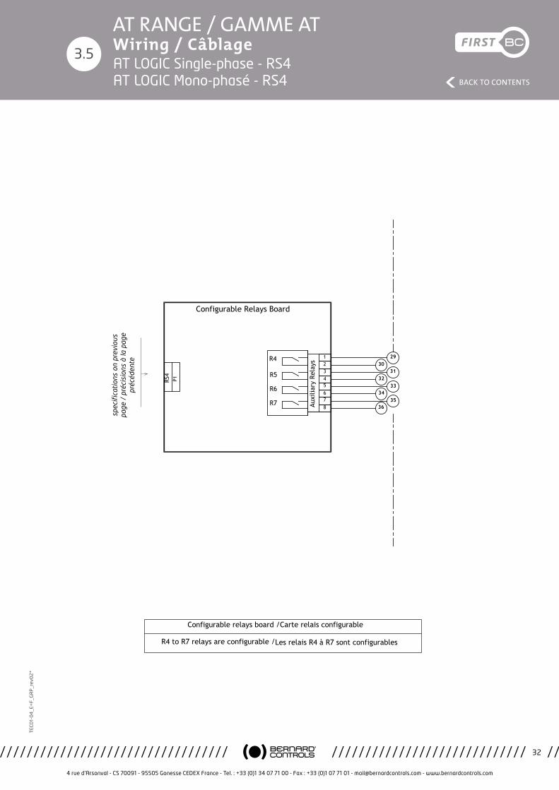
4 rue d’Arsonval - CS 70091 - 95505 Gonesse CEDEX France - Tel. : +33 (0)1 34 07 71 00 - Fax : +33 (0)1 07 71 01 - [email protected] - www.bernardcontrols.com
32
BACK TO CONTENTS
TEC
01-
04
_E+
F_G
RP
_rev
02
*AT RANGE / GAMME AT Wiring / Câblage
3.5
Etude/Study:
Ind./Rev.:PROD
Planche/Sheet:
Projet/Project: Modification:
Approuvé/Approved Approuvé/ApprovedDessiné par:Designed by:
Vérifié par:Checked by:
Validé par:Validated by: PROTO
Ce plan étant notre propriété, il ne peut être reproduit ou communiqué sans notre autorisation écrite.This drawing is our property and may not be reproduced or communicated without our written authorization.
4 rue d'Arsonval BP 91 95505 GONESSE CEDEX
www.bernardcontrols.com
PBCDT16010
D
DM17374
AT/AQ-25 à 50 MONOPHASEE LOGIC SINGLE PHASE AT/AQ-25 to 50 LOGIC
WD_630028_FREN
RS4
RS4
18/12/17
L.Maissin
05/12/17
Montagner
05/12/17 ->->M.Wolosz S.Dadier
21/12/17
RS4
P1
3031
3233
3435
36
29
Auxi
liary
Rel
ays
R7
R5
R6
Configurable Relays Board
R4
5678
1234
Configurable relays board /Carte relais configurable
R4 to R7 relays are configurable /Les relais R4 à R7 sont configurables
spec
ifica
tion
s on
pre
viou
s pa
ge /
pré
cisi
ons
à la
pag
e pr
écéd
ente
AT LOGIC Single-phase - RS4 AT LOGIC Mono-phasé - RS4

4 rue d’Arsonval - CS 70091 - 95505 Gonesse CEDEX France - Tel. : +33 (0)1 34 07 71 00 - Fax : +33 (0)1 07 71 01 - [email protected] - www.bernardcontrols.com
33
BACK TO CONTENTS
TEC
01-
04
_E+
F_G
RP
_rev
02
*AT RANGE / GAMME AT Wiring / Câblage
3.6
Emer
genc
y Su
pply
24V
Etud
e/St
udy:
Ind.
/Rev
.:PR
OD
Plan
che/
Shee
t:
Proj
et/P
roje
ct:
Mod
ific
atio
n:
Appr
ouvé
/App
rove
dAp
prou
vé/A
ppro
ved
Dess
iné
par:
Desi
gned
by:
Véri
fié
par:
Chec
ked
by:
Valid
é pa
r:Va
lidat
ed b
y:PR
OTO
Ce p
lan
étan
t no
tre
prop
riété
, il n
e pe
ut ê
tre
repr
odui
t ou
com
mun
iqué
san
s no
tre
auto
risat
ion
écrit
e.Th
is dr
awin
g is
our p
rope
rty
and
may
not
be
repr
oduc
ed o
r com
mun
icat
ed w
ithou
t ou
r writ
ten
auth
oriz
atio
n.
4 ru
e d'
Arso
nval
BP
91
9550
5 G
ON
ESSE
CED
EX
ww
w.b
erna
rdco
ntro
ls.c
om
PBCD
T160
10
D
DM17
374
AT/A
Q-2
5 à
50 T
RIPH
ASEE
LO
GIC
TH
REE
PHAS
E AT
/AQ
-25
to 5
0 LO
GIC
WD_
6300
29_F
REN
RS4
RS4
18/1
2/17
L.M
aiss
in
05/1
2/17
Mon
tagn
er
05/1
2/17
->->M
.Wol
osz
S.Da
dier
21
/12/
17
9
10
11
Lége
nde
/ Le
gend
CAux1
CO
6
7
8
3
4
5
10 à
60V
S
Conn
ecti
on f
or c
ontr
ol b
y vo
ltag
e Ra
ccor
dem
ents
pou
r cd
e pa
r te
nsio
n
90 à
250
V
Not
e:
SOAux2
To c
ance
l se
lf h
oldi
ng c
md
Do
not
conn
ect
term
inal
7Po
ur s
uppr
imer
l'au
tom
aint
ien
ne p
as r
acco
rder
la b
orne
7
TH
Conn
ecti
on f
or c
ontr
ol b
y co
ntac
t Ra
ccor
dem
ents
pou
r cd
e pa
r co
ntac
t
CO
S
2827
4 3 2 19 8 7
SIGNALLING
R1R3 R2RD
1
P11 6 5
2625
2423
2221
20
LOCAL CONTROL
8 9 10 113 4 5
REMOTE COMMANDS
P13 6 7
34
56
78
910
11
1 2 3 4 5 6
1 21
2
321
COIL
3 4 51 2J2Ca
pteu
r de
Cou
ple
Capt
eur
de P
osit
ion
Torq
ue S
enso
r
Posi
tion
sen
sor
11
10
9
8
7
6
5
4
3
P7 P51 2TH
P6
65
43
21
19V
23V
L Ph
Cont
rol b
y vo
ltag
e
Out
put
Supp
ly 2
4V
Cont
rol b
y Co
ntac
t
Aux
1 &
Aux
2
CI28
02
-
-
+
+
RS4
P1
4
DD
R2R1
12Em
erge
ncy
supp
ly in
put
RDR3
+En
trée
alim
enta
tion
de
seco
urs
-
Cust
omer
Con
figu
rati
on
Conf
igur
atio
n Cl
ient
POSITION &
TORQUE
U X 1AA U X 2
U X 1AA U X 2
Conf
igur
able
com
man
d Co
mm
ande
con
figu
rabl
e
Conf
igur
able
com
man
d Co
mm
ande
con
figu
rabl
e
Clos
ing
com
man
d Co
mm
ande
fer
met
ure
Ope
ning
com
man
d Co
mm
ande
ouv
ertu
re
Stop
Ther
mal
pro
tect
ion
Prot
ecti
on t
herm
ique
L2/L
L3L1
/N
Tran
sfor
mer
Bo
ard
19V
23V
L Ph
13 2
M3
C2A1
A2
C1A1
A2
The
phas
e se
quen
cy is
not
impo
rtan
t If
one
pha
se is
mis
sing
, th
e ac
tuat
or w
ill n
ot s
tart
and
se
nds
an a
larm
(Fa
ult
rela
y).
L'or
dre
des
phas
es n
'a p
as d
'impo
rtan
ce.
Si l'
une
d'el
les
est
man
quan
te,
le s
ervo
mot
eur
ne
redé
mar
re p
as e
t si
gnal
e le
déf
aut
(Rel
ais
défa
ut).
PE
L1/N
L2/L
L3
DISP
LAY
Hea
ter
Chau
ffag
e
Valv
e op
enVa
nne
ouve
rte
Valv
e cl
osed
Vann
e fe
rmée
Conf
igur
able
rel
ay R
elai
s co
nfig
urab
le
Faul
t re
lay
term
inal
26-
28 c
lose
d=
actu
ator
ava
ilabl
eRe
lais
déf
aut
cont
act
26-2
8 fe
rmé=
se
rvom
oteu
r di
spon
ible
spec
ifica
tion
s on
nex
t pa
ge /
pr
écis
ions
à la
pag
e su
ivan
te
see customer configuration / voir configuration client
Mot
or /
Mot
eur
Cust
omer
Ter
min
als
/
Bor
nes
clie
nt
The
pha
se s
eque
ncy
is n
ot im
port
ant
if o
ne p
hase
is m
issi
ng, t
he a
ctua
tor
will
not
sta
rt a
nd s
ends
an
alar
m (
Faul
t re
lay)
. L’
ordr
e de
s ph
ases
n’a
pas
d’im
port
ance
. Si l
’une
d’e
lles
est
man
quan
te, l
e se
rvom
oteu
r ne
red
émar
re p
as e
t si
gnal
e le
déf
aut
(Rel
ais
défa
ut)
Emergency Supply 24V
Etude/Study:
Ind./Rev.:PROD
Planche/Sheet:
Projet/Project: Modification:
Approuvé/Approved Approuvé/ApprovedDessiné par:Designed by:
Vérifié par:Checked by:
Validé par:Validated by: PROTO
Ce plan étant notre propriété, il ne peut être reproduit ou communiqué sans notre autorisation écrite.This drawing is our property and may not be reproduced or communicated without our written authorization.
4 rue d'Arsonval BP 91 95505 GONESSE CEDEX
www.bernardcontrols.com
PBCDT16010
D
DM17374
AT/AQ-25 à 50 TRIPHASEE LOGIC THREE PHASE AT/AQ-25 to 50 LOGIC
WD_630029_FREN
RS4
RS4
18/12/17
L.Maissin
05/12/17
Montagner
05/12/17 ->->M.Wolosz S.Dadier
21/12/17
9
10
11
Légende / Legend
C
Aux1
C O
6
7
8
3
4
5
10 à 60V
S
Connection for control by voltage Raccordements pour cde par tension
90 à 250V
Note:
S
O
Aux2
To cancel self holding cmd Do not connect terminal 7Pour supprimer l'automaintien ne pas raccorder la borne 7
TH
Connection for control by contact Raccordements pour cde par contact
C O
S
2827
4321
987
SIG
NAL
LIN
G
R1
R3
R2
RD
1
P11
65
2625
2423
2221
20
LOCA
L CO
NTR
OL
891011
345
REM
OTE
CO
MM
ANDS
P13
67
34
56
78
910
11
123456
12
12
321
COIL
345
12
J2Capteur de Couple
Capteur de Position
Torque Sensor
Position sensor
11
10
9
8
7
6
5
4
3
P7
P5
12 TH
P6
6 5 4 3 2 1
19V 23V L Ph
Control by voltage
Output Supply 24V
Control by Contact
Aux 1 & Aux 2
CI2802
-
-
+
+
RS4P1
4
DD
R2
R1
1
2 Emergency supply input
RD
R3
+ Entrée alimentation de secours
-
Customer Configuration Configuration Client
POSI
TIO
N &
TORQ
UE
UX1
A AUX2
UX1
A AUX2
Configurable command Commande configurable
Configurable command Commande configurable
Closing command Commande fermeture
Opening command Commande ouverture
Stop
Thermal protection Protection thermique
L2/L L3 L1/N
Transformer Board
19V 23V L Ph1
32
M3
C2A1
A2 C1A1
A2The phase sequency is not important If one phase is missing, the actuator will not start and sends an alarm (Fault relay).
L'ordre des phases n'a pas d'importance.Si l'une d'elles est manquante, le servomoteur ne redémarre pas et signale le défaut (Relais défaut).
PE
L1/N
L2/L
L3
DISPLAY
Heater Chauffage
Valve openVanne ouverte
Valve closedVanne fermée
Configurable relay Relais configurable
Fault relayterminal 26-28 closed= actuator availableRelais défautcontact 26-28 fermé= servomoteur disponible
AT LOGIC 3-phases - RS4 AT LOGIC Triphasé - RS4
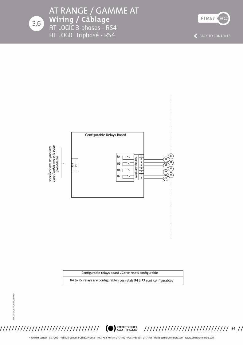
4 rue d’Arsonval - CS 70091 - 95505 Gonesse CEDEX France - Tel. : +33 (0)1 34 07 71 00 - Fax : +33 (0)1 07 71 01 - [email protected] - www.bernardcontrols.com
34
BACK TO CONTENTS
TEC
01-
04
_E+
F_G
RP
_rev
02
*AT RANGE / GAMME AT Wiring / Câblage
3.6
Etude/Study:
Ind./Rev.:PROD
Planche/Sheet:
Projet/Project: Modification:
Approuvé/Approved Approuvé/ApprovedDessiné par:Designed by:
Vérifié par:Checked by:
Validé par:Validated by: PROTO
Ce plan étant notre propriété, il ne peut être reproduit ou communiqué sans notre autorisation écrite.This drawing is our property and may not be reproduced or communicated without our written authorization.
4 rue d'Arsonval BP 91 95505 GONESSE CEDEX
www.bernardcontrols.com
PBCDT16010
D
DM17374
AT/AQ-25 à 50 TRIPHASEE LOGIC THREE PHASE AT/AQ-25 to 50 LOGIC
WD_630029_FREN
RS4
RS4
18/12/17
L.Maissin
05/12/17
Montagner
05/12/17 ->->M.Wolosz S.Dadier
21/12/17
RS4
P1
3031
3233
3435
36
29
Auxi
liary
Rel
ays
R7
R5
R6
Configurable Relays Board
R4
5678
1234
Configurable relays board /Carte relais configurable
R4 to R7 relays are configurable /Les relais R4 à R7 sont configurables
spec
ifica
tion
s on
pre
viou
s pa
ge /
pré
cisi
ons
à la
pag
e pr
écéd
ente
AT LOGIC 3-phases - RS4 AT LOGIC Triphasé - RS4
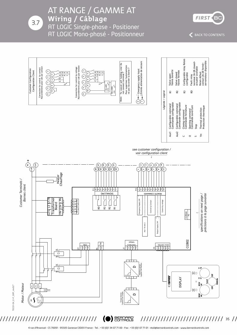
4 rue d’Arsonval - CS 70091 - 95505 Gonesse CEDEX France - Tel. : +33 (0)1 34 07 71 00 - Fax : +33 (0)1 07 71 01 - [email protected] - www.bernardcontrols.com
35
BACK TO CONTENTS
TEC
01-
04
_E+
F_G
RP
_rev
02
*AT RANGE / GAMME AT Wiring / Câblage
3.7
Emer
genc
y Su
pply
24V
Etud
e/St
udy:
Ind.
/Rev
.:PR
OD
Plan
che/
Shee
t:
Proj
et/P
roje
ct:
Mod
ific
atio
n:
Appr
ouvé
/App
rove
dAp
prou
vé/A
ppro
ved
Dess
iné
par:
Desi
gned
by:
Véri
fié
par:
Chec
ked
by:
Valid
é pa
r:Va
lidat
ed b
y:PR
OTO
Ce p
lan
étan
t no
tre
prop
riété
, il n
e pe
ut ê
tre
repr
odui
t ou
com
mun
iqué
san
s no
tre
auto
risat
ion
écrit
e.Th
is dr
awin
g is
our p
rope
rty
and
may
not
be
repr
oduc
ed o
r com
mun
icat
ed w
ithou
t ou
r writ
ten
auth
oriz
atio
n.
4 ru
e d'
Arso
nval
BP
91
9550
5 G
ON
ESSE
CED
EX
ww
w.b
erna
rdco
ntro
ls.c
om
PBCD
T160
10
D
DM17
374
AT/A
Q-2
5 à
50
MO
NO
PHAS
EE
LOG
IC
SIN
GLE
PH
ASE
AT/A
Q-2
5 to
50
LOG
IC
WD_
6300
30_F
REN
Posi
tion
neur
Posi
tion
er
18/1
2/17
L.M
aiss
in
05/1
2/17
Mon
tagn
er
05/1
2/17
->->M
.Wol
osz
S.Da
dier
21
/12/
17
9
10
11
Lége
nde
/ Le
gend
CAux1
CO
6
7
8
3
4
5
10 à
60V
S
Conn
ecti
on f
or c
ontr
ol b
y vo
ltag
e Ra
ccor
dem
ents
pou
r cd
e pa
r te
nsio
n
90 à
250
V
Not
e:
SOAux2
To c
ance
l se
lf h
oldi
ng c
md
Do
not
conn
ect
term
inal
7Po
ur s
uppr
imer
l'au
tom
aint
ien
ne p
as r
acco
rder
la b
orne
7
TH
Conn
ecti
on f
or c
ontr
ol b
y co
ntac
t Ra
ccor
dem
ents
pou
r cd
e pa
r co
ntac
t
CO
S
2827
4 3 2 19 8 7
SIGNALLING
R1R3 R2RD
1
P11 6 5
2625
2423
2221
20
LOCAL CONTROL
8 9 10 113 4 5
REMOTE COMMANDS
P13 6 7
34
56
78
910
11
1 2 3 4 5 6
1 21
2
321
COIL
3 4 51 2J2Ca
pteu
r de
Cou
ple
Capt
eur
de P
osit
ion
Torq
ue S
enso
r
Posi
tion
sen
sor
11
10
9
8
7
6
5
4
3
P7 P51 2TH
P6
65
43
21
19V
23V
L Ph
4-20
mA
P2
Cont
rol b
y vo
ltag
e
Out
put
Supp
ly 2
4V
Cont
rol b
y Co
ntac
t
Aux
1 &
Aux
2
CI28
02
-
-
+
+
4
DD
R2R1
12Em
erge
ncy
supp
ly in
put
RDR3
+En
trée
alim
enta
tion
de
seco
urs
-
Cust
omer
Con
figu
rati
on
Conf
igur
atio
n Cl
ient
POSITION &
TORQUE
U X 1AA U X 2
U X 1AA U X 2
Conf
igur
able
com
man
d Co
mm
ande
con
figu
rabl
e
Conf
igur
able
com
man
d Co
mm
ande
con
figu
rabl
e
Clos
ing
com
man
d Co
mm
ande
fer
met
ure
Ope
ning
com
man
d Co
mm
ande
ouv
ertu
re
Stop
Ther
mal
pro
tect
ion
Prot
ecti
on t
herm
ique
13 2
M1
C2A1
A2
C1A1
A2
L2/L
L3L1
/N
Tran
sfor
mer
Bo
ard
19V
23V
L Ph
PE
L1/N
L2/L
DISP
LAY
Hea
ter
Chau
ffag
e
Valv
e op
enVa
nne
ouve
rte
Valv
e cl
osed
Vann
e fe
rmée
Conf
igur
able
rel
ay R
elai
s co
nfig
urab
le
Faul
t re
lay
term
inal
26-
28 c
lose
d=
actu
ator
ava
ilabl
eRe
lais
déf
aut
cont
act
26-2
8 fe
rmé=
se
rvom
oteu
r di
spon
ible
spec
ifica
tion
s on
nex
t pa
ge /
pr
écis
ions
à la
pag
e su
ivan
te
see customer configuration / voir configuration client
Mot
or /
Mot
eur
Cust
omer
Ter
min
als
/
Bor
nes
clie
ntAT LOGIC Single-phase - Positioner AT LOGIC Mono-phasé - Positionneur

4 rue d’Arsonval - CS 70091 - 95505 Gonesse CEDEX France - Tel. : +33 (0)1 34 07 71 00 - Fax : +33 (0)1 07 71 01 - [email protected] - www.bernardcontrols.com
36
BACK TO CONTENTS
TEC
01-
04
_E+
F_G
RP
_rev
02
*AT RANGE / GAMME AT Wiring / Câblage
3.7
Etude/Study:
Ind./Rev.:PROD
Planche/Sheet:
Projet/Project: Modification:
Approuvé/Approved Approuvé/ApprovedDessiné par:Designed by:
Vérifié par:Checked by:
Validé par:Validated by: PROTO
Ce plan étant notre propriété, il ne peut être reproduit ou communiqué sans notre autorisation écrite.This drawing is our property and may not be reproduced or communicated without our written authorization.
4 rue d'Arsonval BP 91 95505 GONESSE CEDEX
www.bernardcontrols.com
PBCDT16010
D
DM17374
AT/AQ-25 à 50 MONOPHASEE LOGIC SINGLE PHASE AT/AQ-25 to 50 LOGIC
WD_630030_FREN
Positionneur
Positioner
18/12/17
L.Maissin
05/12/17
Montagner
05/12/17 ->->M.Wolosz S.Dadier
21/12/17
4-20
mA
P2
1314
1516
1718
19
5678
234
Torque transmitter
Position transmitter
Analog input setpoint ANA
IN/O
UT
Inte
rfac
e
1 12
4-20mA
0/4 - 20 mA
(1) Possibilité d'utiliser l'alimentation 24 Vcc des bornes 8-9
(1) Possibility to use 24 Vdc supply on terminals 8-9
12 to 32VDCmA (1)
Raccordement pour 4/20mA(2 fils) Connection for 4/20mA (2 wires)
12
13
14
15
12 to 32VDC (1)
Raccordement pour 4/20mA(3 fils)Connection for 4/20mA ou 0/20mA
mA
12
13
14
15
(3 wires)
Position transmitter option / Option recopie de position
12 to 32VDCmA (1)
16
17
19
18
-
+ Analog input setpoint
Torque transmitter option Option recopie de couple
+
-
-
+
Positioner Board
Entrée de commande analogique
spec
ifica
tion
s on
pre
viou
s pa
ge /
pré
cisi
ons
à la
pag
e pr
écéd
ente
see
lege
nd /
voi
r la
lége
nde
AT LOGIC Single-phase - Positioner AT LOGIC Mono-phasé - Positionneur
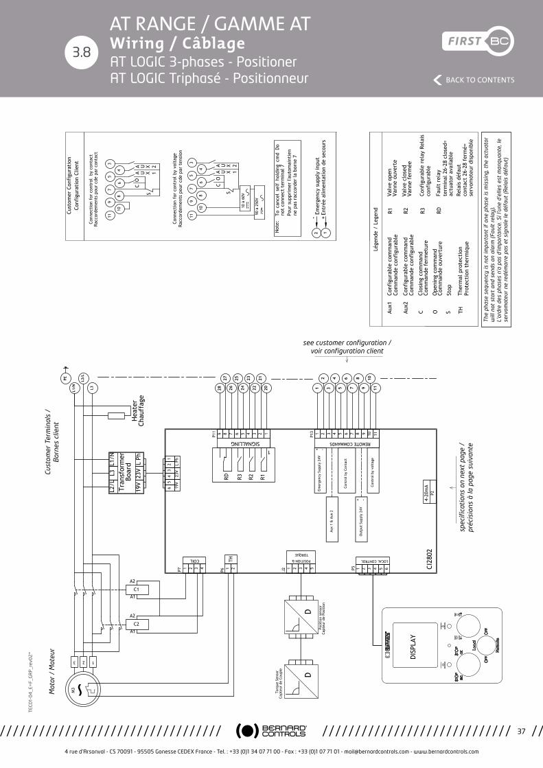
4 rue d’Arsonval - CS 70091 - 95505 Gonesse CEDEX France - Tel. : +33 (0)1 34 07 71 00 - Fax : +33 (0)1 07 71 01 - [email protected] - www.bernardcontrols.com
37
BACK TO CONTENTS
TEC
01-
04
_E+
F_G
RP
_rev
02
*AT RANGE / GAMME AT Wiring / Câblage
3.8
Emer
genc
y Su
pply
24V
Etud
e/St
udy:
Ind.
/Rev
.:PR
OD
Plan
che/
Shee
t:
Proj
et/P
roje
ct:
Mod
ific
atio
n:
Appr
ouvé
/App
rove
dAp
prou
vé/A
ppro
ved
Dess
iné
par:
Desi
gned
by:
Véri
fié
par:
Chec
ked
by:
Valid
é pa
r:Va
lidat
ed b
y:PR
OTO
Ce p
lan
étan
t no
tre
prop
riété
, il n
e pe
ut ê
tre
repr
odui
t ou
com
mun
iqué
san
s no
tre
auto
risat
ion
écrit
e.Th
is dr
awin
g is
our p
rope
rty
and
may
not
be
repr
oduc
ed o
r com
mun
icat
ed w
ithou
t ou
r writ
ten
auth
oriz
atio
n.
4 ru
e d'
Arso
nval
BP
91
9550
5 G
ON
ESSE
CED
EX
ww
w.b
erna
rdco
ntro
ls.c
om
PBCD
T160
10
D
DM17
374
AT/A
Q-2
5 à
50 T
RIPH
ASEE
LO
GIC
TH
REE
PHAS
E AT
/AQ
-25-
to
50 L
OG
IC
WD_
6300
31_F
REN
Posi
tion
neur
Posi
tion
er
18/1
2/17
L.M
aiss
in
05/1
2/17
Mon
tagn
er
05/1
2/17
->->M
.Wol
osz
S.Da
dier
21
/12/
17
9
10
11
Lége
nde
/ Le
gend
CAux1
CO
6
7
8
3
4
5
10 à
60V
S
Conn
ecti
on f
or c
ontr
ol b
y vo
ltag
e Ra
ccor
dem
ents
pou
r cd
e pa
r te
nsio
n
90 à
250
V
Not
e:
SOAux2
To c
ance
l se
lf h
oldi
ng c
md
Do
not
conn
ect
term
inal
7Po
ur s
uppr
imer
l'au
tom
aint
ien
ne p
as r
acco
rder
la b
orne
7
TH
Conn
ecti
on f
or c
ontr
ol b
y co
ntac
t Ra
ccor
dem
ents
pou
r cd
e pa
r co
ntac
t
CO
S
2827
4 3 2 19 8 7
SIGNALLING
R1R3 R2RD
1
P11 6 5
2625
2423
2221
20
LOCAL CONTROL
8 9 10 113 4 5
REMOTE COMMANDS
P13 6 7
34
56
78
910
11
1 2 3 4 5 6
1 21
2
321
COIL
3 4 51 2J2Ca
pteu
r de
Cou
ple
Capt
eur
de P
osit
ion
Torq
ue S
enso
r
Posi
tion
sen
sor
11
10
9
8
7
6
5
4
3
P7 P51 2TH
P6
65
43
21
19V
23V
L Ph
4-20
mA
P2
Cont
rol b
y vo
ltag
e
Out
put
Supp
ly 2
4V
Cont
rol b
y Co
ntac
t
Aux
1 &
Aux
2
CI28
02
-
-
+
+
4
DD
R2R1
12Em
erge
ncy
supp
ly in
put
RDR3
+En
trée
alim
enta
tion
de
seco
urs
-
Cust
omer
Con
figu
rati
on
Conf
igur
atio
n Cl
ient
POSITION &
TORQUE
U X 1AA U X 2
U X 1AA U X 2
Conf
igur
able
com
man
d Co
mm
ande
con
figu
rabl
e
Conf
igur
able
com
man
d Co
mm
ande
con
figu
rabl
e
Clos
ing
com
man
d Co
mm
ande
fer
met
ure
Ope
ning
com
man
d Co
mm
ande
ouv
ertu
re
Stop
Ther
mal
pro
tect
ion
Prot
ecti
on t
herm
ique
L2/L
L3L1
/N
Tran
sfor
mer
Bo
ard
19V
23V
L Ph
13 2
M3
C2A1
A2
C1A1
A2
The
phas
e se
quen
cy is
not
impo
rtan
t If
one
pha
se is
mis
sing
, th
e ac
tuat
or w
ill n
ot s
tart
and
se
nds
an a
larm
(Fa
ult
rela
y).
L'or
dre
des
phas
es n
'a p
as d
'impo
rtan
ce.
Si l'
une
d'el
les
est
man
quan
te,
le s
ervo
mot
eur
ne
redé
mar
re p
as e
t si
gnal
e le
déf
aut
(Rel
ais
défa
ut).
PE
L1/N
L2/L
L3
DISP
LAY
Hea
ter
Chau
ffag
e
Valv
e op
enVa
nne
ouve
rte
Valv
e cl
osed
Vann
e fe
rmée
Conf
igur
able
rel
ay R
elai
s co
nfig
urab
le
Faul
t re
lay
term
inal
26-
28 c
lose
d=
actu
ator
ava
ilabl
eRe
lais
déf
aut
cont
act
26-2
8 fe
rmé=
se
rvom
oteu
r di
spon
ible
spec
ifica
tion
s on
nex
t pa
ge /
pr
écis
ions
à la
pag
e su
ivan
te
see customer configuration / voir configuration client
Mot
or /
Mot
eur
Cust
omer
Ter
min
als
/
Bor
nes
clie
nt
The
pha
se s
eque
ncy
is n
ot im
port
ant
if o
ne p
hase
is m
issi
ng, t
he a
ctua
tor
will
not
sta
rt a
nd s
ends
an
alar
m (
Faul
t re
lay)
. L’
ordr
e de
s ph
ases
n’a
pas
d’im
port
ance
. Si l
’une
d’e
lles
est
man
quan
te, l
e se
rvom
oteu
r ne
red
émar
re p
as e
t si
gnal
e le
déf
aut
(Rel
ais
défa
ut)
Emergency Supply 24V
Etude/Study:
Ind./Rev.:PROD
Planche/Sheet:
Projet/Project: Modification:
Approuvé/Approved Approuvé/ApprovedDessiné par:Designed by:
Vérifié par:Checked by:
Validé par:Validated by: PROTO
Ce plan étant notre propriété, il ne peut être reproduit ou communiqué sans notre autorisation écrite.This drawing is our property and may not be reproduced or communicated without our written authorization.
4 rue d'Arsonval BP 91 95505 GONESSE CEDEX
www.bernardcontrols.com
PBCDT16010
D
DM17374
AT/AQ-25 à 50 TRIPHASEE LOGIC THREE PHASE AT/AQ-25- to 50 LOGIC
WD_630031_FREN
Positionneur
Positioner
18/12/17
L.Maissin
05/12/17
Montagner
05/12/17 ->->M.Wolosz S.Dadier
21/12/17
9
10
11
Légende / Legend
C
Aux1
C O
6
7
8
3
4
5
10 à 60V
S
Connection for control by voltage Raccordements pour cde par tension
90 à 250V
Note:
S
O
Aux2
To cancel self holding cmd Do not connect terminal 7Pour supprimer l'automaintien ne pas raccorder la borne 7
TH
Connection for control by contact Raccordements pour cde par contact
C O
S
2827
4321
987
SIG
NAL
LIN
G
R1
R3
R2
RD
1
P11
65
2625
2423
2221
20
LOCA
L CO
NTR
OL
891011
345
REM
OTE
CO
MM
ANDS
P13
67
34
56
78
910
11
123456
12
12
321
COIL
345
12
J2Capteur de Couple
Capteur de Position
Torque Sensor
Position sensor
11
10
9
8
7
6
5
4
3
P7
P5
12 TH
P6
6 5 4 3 2 1
19V 23V L Ph
4-20mAP2
Control by voltage
Output Supply 24V
Control by Contact
Aux 1 & Aux 2
CI2802
-
-
+
+
4
DD
R2
R1
1
2 Emergency supply input
RD
R3
+ Entrée alimentation de secours
-
Customer Configuration Configuration Client
POSI
TIO
N &
TORQ
UE
UX1
A AUX2
UX1
A AUX2
Configurable command Commande configurable
Configurable command Commande configurable
Closing command Commande fermeture
Opening command Commande ouverture
Stop
Thermal protection Protection thermique
L2/L L3 L1/N
Transformer Board
19V 23V L Ph1
32
M3
C2A1
A2 C1A1
A2The phase sequency is not important If one phase is missing, the actuator will not start and sends an alarm (Fault relay).
L'ordre des phases n'a pas d'importance.Si l'une d'elles est manquante, le servomoteur ne redémarre pas et signale le défaut (Relais défaut).
PE
L1/N
L2/L
L3
DISPLAY
Heater Chauffage
Valve openVanne ouverte
Valve closedVanne fermée
Configurable relay Relais configurable
Fault relayterminal 26-28 closed= actuator availableRelais défautcontact 26-28 fermé= servomoteur disponible
AT LOGIC 3-phases - Positioner AT LOGIC Triphasé - Positionneur
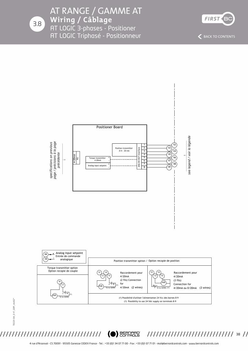
4 rue d’Arsonval - CS 70091 - 95505 Gonesse CEDEX France - Tel. : +33 (0)1 34 07 71 00 - Fax : +33 (0)1 07 71 01 - [email protected] - www.bernardcontrols.com
38
BACK TO CONTENTS
TEC
01-
04
_E+
F_G
RP
_rev
02
*AT RANGE / GAMME AT Wiring / Câblage
3.8
Etude/Study:
Ind./Rev.:PROD
Planche/Sheet:
Projet/Project: Modification:
Approuvé/Approved Approuvé/ApprovedDessiné par:Designed by:
Vérifié par:Checked by:
Validé par:Validated by: PROTO
Ce plan étant notre propriété, il ne peut être reproduit ou communiqué sans notre autorisation écrite.This drawing is our property and may not be reproduced or communicated without our written authorization.
4 rue d'Arsonval BP 91 95505 GONESSE CEDEX
www.bernardcontrols.com
PBCDT16010
D
DM17374
AT/AQ-25 à 50 TRIPHASEE LOGIC THREE PHASE AT/AQ-25- to 50 LOGIC
WD_630031_FREN
Positionneur
Positioner
18/12/17
L.Maissin
05/12/17
Montagner
05/12/17 ->->M.Wolosz S.Dadier
21/12/17
4-20
mA
P2
1314
1516
1718
19
5678
234
Torque transmitter
Position transmitter
Analog input setpoint ANA
IN/O
UT
Inte
rfac
e
1 12
4-20mA
0/4 - 20 mA
(1) Possibilité d'utiliser l'alimentation 24 Vcc des bornes 8-9
(1) Possibility to use 24 Vdc supply on terminals 8-9
12 to 32VDCmA (1)
Raccordement pour 4/20mA(2 fils) Connection for 4/20mA (2 wires)
12
13
14
15
12 to 32VDC (1)
Raccordement pour 4/20mA(3 fils)Connection for 4/20mA ou 0/20mA
mA
12
13
14
15
(3 wires)
Position transmitter option / Option recopie de position
12 to 32VDCmA (1)
16
17
19
18
-
+ Analog input setpoint
Torque transmitter option Option recopie de couple
+
-
-
+
Positioner Board
Entrée de commande analogique
spec
ifica
tion
s on
pre
viou
s pa
ge /
pré
cisi
ons
à la
pag
e pr
écéd
ente
see
lege
nd /
voi
r la
lége
nde
AT LOGIC 3-phases - Positioner AT LOGIC Triphasé - Positionneur
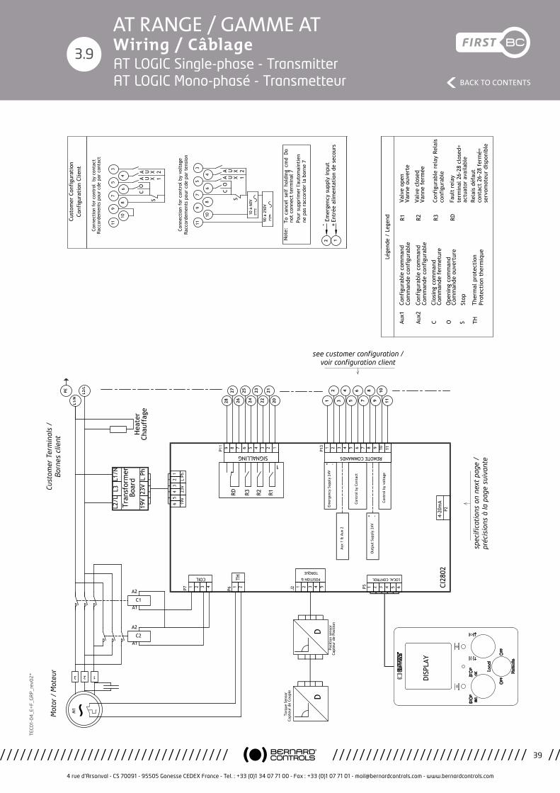
4 rue d’Arsonval - CS 70091 - 95505 Gonesse CEDEX France - Tel. : +33 (0)1 34 07 71 00 - Fax : +33 (0)1 07 71 01 - [email protected] - www.bernardcontrols.com
39
BACK TO CONTENTS
TEC
01-
04
_E+
F_G
RP
_rev
02
*AT RANGE / GAMME AT Wiring / Câblage
3.9
Emer
genc
y Su
pply
24V
Etud
e/St
udy:
Ind.
/Rev
.:PR
OD
Plan
che/
Shee
t:
Proj
et/P
roje
ct:
Mod
ific
atio
n:
Appr
ouvé
/App
rove
dAp
prou
vé/A
ppro
ved
Dess
iné
par:
Desi
gned
by:
Véri
fié
par:
Chec
ked
by:
Valid
é pa
r:Va
lidat
ed b
y:PR
OTO
Ce p
lan
étan
t no
tre
prop
riété
, il n
e pe
ut ê
tre
repr
odui
t ou
com
mun
iqué
san
s no
tre
auto
risat
ion
écrit
e.Th
is dr
awin
g is
our p
rope
rty
and
may
not
be
repr
oduc
ed o
r com
mun
icat
ed w
ithou
t ou
r writ
ten
auth
oriz
atio
n.
4 ru
e d'
Arso
nval
BP
91
9550
5 G
ON
ESSE
CED
EX
ww
w.b
erna
rdco
ntro
ls.c
om
PBCD
T160
10
D
DM17
374
AT/A
Q-2
5 à
50
MO
NO
PHAS
EE
LOG
IC
SIN
GLE
PH
ASE
AT/A
Q-2
5 to
50
LOG
IC
WD_
6300
32_F
REN
Tran
smet
teur
Tran
smit
ter
18/1
2/17
L.M
aiss
in
05/1
2/17
Mon
tagn
er
05/1
2/17
->->M
.Wol
osz
S.Da
dier
21
/12/
17
9
10
11
Lége
nde
/ Le
gend
CAux1
CO
6
7
8
3
4
5
10 à
60V
S
Conn
ecti
on f
or c
ontr
ol b
y vo
ltag
e Ra
ccor
dem
ents
pou
r cd
e pa
r te
nsio
n
90 à
250
V
Not
e:
SOAux2
To c
ance
l se
lf h
oldi
ng c
md
Do
not
conn
ect
term
inal
7Po
ur s
uppr
imer
l'au
tom
aint
ien
ne p
as r
acco
rder
la b
orne
7
TH
Conn
ecti
on f
or c
ontr
ol b
y co
ntac
t Ra
ccor
dem
ents
pou
r cd
e pa
r co
ntac
t
CO
S
2827
4 3 2 19 8 7
SIGNALLING
R1R3 R2RD
1
P11 6 5
2625
2423
2221
20
LOCAL CONTROL
8 9 10 113 4 5
REMOTE COMMANDS
P13 6 7
34
56
78
910
11
1 2 3 4 5 6
1 21
2
321
COIL
3 4 51 2J2Ca
pteu
r de
Cou
ple
Capt
eur
de P
osit
ion
Torq
ue S
enso
r
Posi
tion
sen
sor
11
10
9
8
7
6
5
4
3
P7 P51 2TH
P6
65
43
21
19V
23V
L Ph
Cont
rol b
y vo
ltag
e
Out
put
Supp
ly 2
4V
Cont
rol b
y Co
ntac
t
Aux
1 &
Aux
2
CI28
02
-
-
+
+
4
DD
R2R1
12Em
erge
ncy
supp
ly in
put
RDR3
+En
trée
alim
enta
tion
de
seco
urs
-
Cust
omer
Con
figu
rati
on
Conf
igur
atio
n Cl
ient
POSITION &
TORQUE
U X 1AA U X 2
U X 1AA U X 2
Conf
igur
able
com
man
d Co
mm
ande
con
figu
rabl
e
Conf
igur
able
com
man
d Co
mm
ande
con
figu
rabl
e
Clos
ing
com
man
d Co
mm
ande
fer
met
ure
Ope
ning
com
man
d Co
mm
ande
ouv
ertu
re
Stop
Ther
mal
pro
tect
ion
Prot
ecti
on t
herm
ique
13 2
M1
C2A1
A2
C1A1
A2
L2/L
L3L1
/N
Tran
sfor
mer
Bo
ard
19V
23V
L Ph
PE
L1/N
L2/L
4-20
mA
P2
DISP
LAY
Hea
ter
Chau
ffag
e
Valv
e op
enVa
nne
ouve
rte
Valv
e cl
osed
Vann
e fe
rmée
Conf
igur
able
rel
ay R
elai
s co
nfig
urab
le
Faul
t re
lay
term
inal
26-
28 c
lose
d=
actu
ator
ava
ilabl
eRe
lais
déf
aut
cont
act
26-2
8 fe
rmé=
se
rvom
oteu
r di
spon
ible
spec
ifica
tion
s on
nex
t pa
ge /
pr
écis
ions
à la
pag
e su
ivan
te
see customer configuration / voir configuration client
Mot
or /
Mot
eur
Cust
omer
Ter
min
als
/
Bor
nes
clie
ntAT LOGIC Single-phase - Transmitter AT LOGIC Mono-phasé - Transmetteur
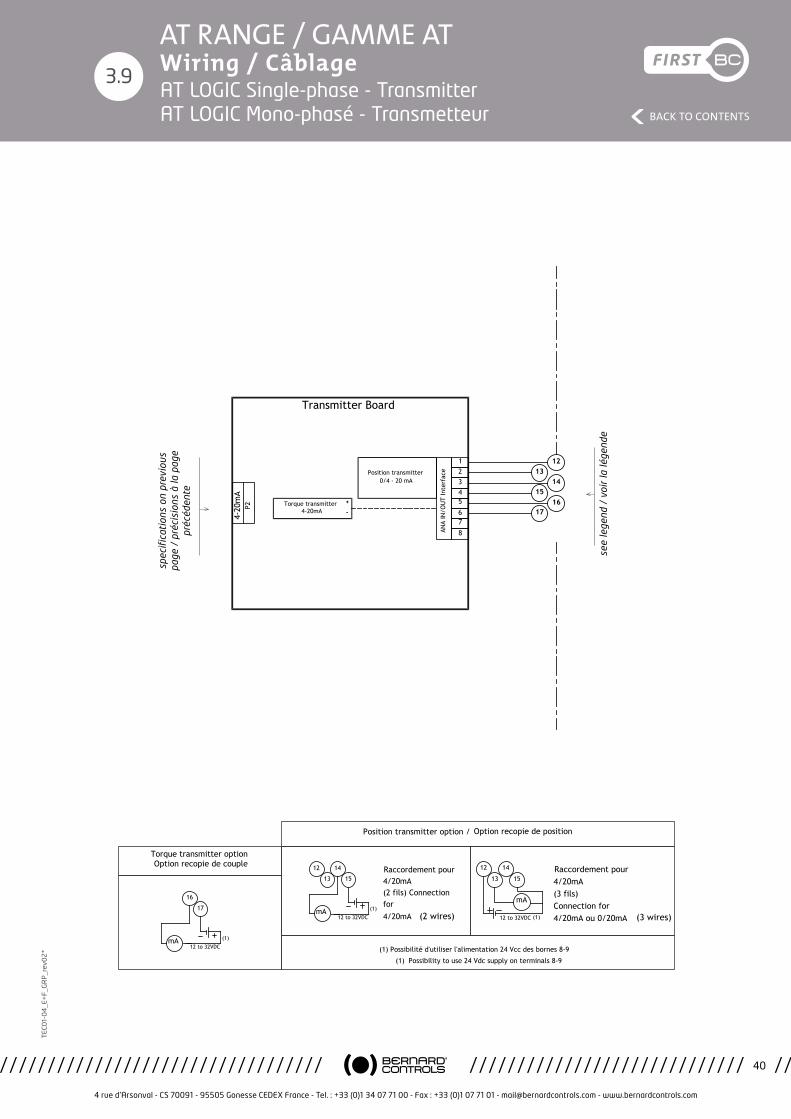
4 rue d’Arsonval - CS 70091 - 95505 Gonesse CEDEX France - Tel. : +33 (0)1 34 07 71 00 - Fax : +33 (0)1 07 71 01 - [email protected] - www.bernardcontrols.com
40
BACK TO CONTENTS
TEC
01-
04
_E+
F_G
RP
_rev
02
*AT RANGE / GAMME AT Wiring / Câblage
3.9
Etude/Study:
Ind./Rev.:PROD
Planche/Sheet:
Projet/Project: Modification:
Approuvé/Approved Approuvé/ApprovedDessiné par:Designed by:
Vérifié par:Checked by:
Validé par:Validated by: PROTO
Ce plan étant notre propriété, il ne peut être reproduit ou communiqué sans notre autorisation écrite.This drawing is our property and may not be reproduced or communicated without our written authorization.
4 rue d'Arsonval BP 91 95505 GONESSE CEDEX
www.bernardcontrols.com
PBCDT16010
D
DM17374
AT/AQ-25 à 50 MONOPHASEE LOGIC SINGLE PHASE AT/AQ-25 to 50 LOGIC
WD_630032_FREN
Transmetteur
Transmitter
18/12/17
L.Maissin
05/12/17
Montagner
05/12/17 ->->M.Wolosz S.Dadier
21/12/17
4-20
mA
P2
13
15
175678
234
Torque transmitter
Position transmitter
ANA
IN/O
UT
Inte
rfac
e
1
4-20mA
0/4 - 20 mA
+
-
Transmitter Board
14
16
12
(1) Possibilité d'utiliser l'alimentation 24 Vcc des bornes 8-9
(1) Possibility to use 24 Vdc supply on terminals 8-9
12 to 32VDCmA (1)
Raccordement pour 4/20mA(2 fils) Connection for 4/20mA (2 wires)
12
13
14
15
12 to 32VDC (1)
Raccordement pour 4/20mA(3 fils)Connection for 4/20mA ou 0/20mA
mA
12
13
14
15
(3 wires)
Position transmitter option / Option recopie de position
12 to 32VDCmA (1)
16
17
Torque transmitter option Option recopie de couple
see
lege
nd /
voi
r la
lége
nde
spec
ifica
tion
s on
pre
viou
s pa
ge /
pré
cisi
ons
à la
pag
e pr
écéd
ente
AT LOGIC Single-phase - Transmitter AT LOGIC Mono-phasé - Transmetteur

4 rue d’Arsonval - CS 70091 - 95505 Gonesse CEDEX France - Tel. : +33 (0)1 34 07 71 00 - Fax : +33 (0)1 07 71 01 - [email protected] - www.bernardcontrols.com
41
BACK TO CONTENTS
TEC
01-
04
_E+
F_G
RP
_rev
02
*AT RANGE / GAMME AT Wiring / Câblage
3.10
Emer
genc
y Su
pply
24V
Etud
e/St
udy:
Ind.
/Rev
.:PR
OD
Plan
che/
Shee
t:
Proj
et/P
roje
ct:
Mod
ific
atio
n:
Appr
ouvé
/App
rove
dAp
prou
vé/A
ppro
ved
Dess
iné
par:
Desi
gned
by:
Véri
fié
par:
Chec
ked
by:
Valid
é pa
r:Va
lidat
ed b
y:PR
OTO
Ce p
lan
étan
t no
tre
prop
riété
, il n
e pe
ut ê
tre
repr
odui
t ou
com
mun
iqué
san
s no
tre
auto
risat
ion
écrit
e.Th
is dr
awin
g is
our p
rope
rty
and
may
not
be
repr
oduc
ed o
r com
mun
icat
ed w
ithou
t ou
r writ
ten
auth
oriz
atio
n.
4 ru
e d'
Arso
nval
BP
91
9550
5 G
ON
ESSE
CED
EX
ww
w.b
erna
rdco
ntro
ls.c
om
PBCD
T160
10
D
DM17
374
AT/A
Q-2
5 à
50 T
RIPH
ASEE
LO
GIC
TH
REE
PHAS
E AT
/AQ
-25
to 5
0 LO
GIC
WD_
6300
33_F
REN
Tran
smet
teur
Tran
smit
ter
18/1
2/17
L.M
aiss
in
05/1
2/17
Mon
tagn
er
05/1
2/17
->->M
.Wol
osz
S.Da
dier
21
/12/
17
9
10
11
Lége
nde
/ Le
gend
CAux1
CO
6
7
8
3
4
5
10 à
60V
S
Conn
ecti
on f
or c
ontr
ol b
y vo
ltag
e Ra
ccor
dem
ents
pou
r cd
e pa
r te
nsio
n
90 à
250
V
Not
e:
SOAux2
To c
ance
l se
lf h
oldi
ng c
md
Do
not
conn
ect
term
inal
7Po
ur s
uppr
imer
l'au
tom
aint
ien
ne p
as r
acco
rder
la b
orne
7
TH
Conn
ecti
on f
or c
ontr
ol b
y co
ntac
t Ra
ccor
dem
ents
pou
r cd
e pa
r co
ntac
t
CO
S
2827
4 3 2 19 8 7
SIGNALLING
R1R3 R2RD
1
P11 6 5
2625
2423
2221
20
LOCAL CONTROL
8 9 10 113 4 5
REMOTE COMMANDS
P13 6 7
34
56
78
910
11
1 2 3 4 5 6
1 21
2
321
COIL
3 4 51 2J2Ca
pteu
r de
Cou
ple
Capt
eur
de P
osit
ion
Torq
ue S
enso
r
Posi
tion
sen
sor
11
10
9
8
7
6
5
4
3
P7 P51 2TH
P6
65
43
21
19V
23V
L Ph
Cont
rol b
y vo
ltag
e
Out
put
Supp
ly 2
4V
Cont
rol b
y Co
ntac
t
Aux
1 &
Aux
2
CI28
02
-
-
+
+
4
DD
R2R1
12Em
erge
ncy
supp
ly in
put
RDR3
+En
trée
alim
enta
tion
de
seco
urs
-
Cust
omer
Con
figu
rati
on
Conf
igur
atio
n Cl
ient
POSITION &
TORQUE
U X 1AA U X 2
U X 1AA U X 2
Conf
igur
able
com
man
d Co
mm
ande
con
figu
rabl
e
Conf
igur
able
com
man
d Co
mm
ande
con
figu
rabl
e
Clos
ing
com
man
d Co
mm
ande
fer
met
ure
Ope
ning
com
man
d Co
mm
ande
ouv
ertu
re
Stop
Ther
mal
pro
tect
ion
Prot
ecti
on t
herm
ique
L2/L
L3L1
/N
Tran
sfor
mer
Bo
ard
19V
23V
L Ph
13 2
M3
C2A1
A2
C1A1
A2
The
phas
e se
quen
cy is
not
impo
rtan
t If
one
pha
se is
mis
sing
, th
e ac
tuat
or w
ill n
ot s
tart
and
se
nds
an a
larm
(Fa
ult
rela
y).
L'or
dre
des
phas
es n
'a p
as d
'impo
rtan
ce.
Si l'
une
d'el
les
est
man
quan
te,
le s
ervo
mot
eur
ne
redé
mar
re p
as e
t si
gnal
e le
déf
aut
(Rel
ais
défa
ut).
PE
L1/N
L2/L
L3
4-20
mA
P2
DISP
LAY
Hea
ter
Chau
ffag
e
Valv
e op
enVa
nne
ouve
rte
Valv
e cl
osed
Vann
e fe
rmée
Conf
igur
able
rel
ay R
elai
s co
nfig
urab
le
Faul
t re
lay
term
inal
26-
28 c
lose
d=
actu
ator
ava
ilabl
eRe
lais
déf
aut
cont
act
26-2
8 fe
rmé=
se
rvom
oteu
r di
spon
ible
spec
ifica
tion
s on
nex
t pa
ge /
pr
écis
ions
à la
pag
e su
ivan
te
see customer configuration / voir configuration client
Mot
or /
Mot
eur
Cust
omer
Ter
min
als
/
Bor
nes
clie
nt
The
pha
se s
eque
ncy
is n
ot im
port
ant
if o
ne p
hase
is m
issi
ng, t
he a
ctua
tor
will
not
sta
rt a
nd s
ends
an
alar
m (
Faul
t re
lay)
. L’
ordr
e de
s ph
ases
n’a
pas
d’im
port
ance
. Si l
’une
d’e
lles
est
man
quan
te, l
e se
rvom
oteu
r ne
red
émar
re p
as e
t si
gnal
e le
déf
aut
(Rel
ais
défa
ut)
AT LOGIC 3-phases - Transmitter AT LOGIC Triphasé - Transmetteur

4 rue d’Arsonval - CS 70091 - 95505 Gonesse CEDEX France - Tel. : +33 (0)1 34 07 71 00 - Fax : +33 (0)1 07 71 01 - [email protected] - www.bernardcontrols.com
42
BACK TO CONTENTS
TEC
01-
04
_E+
F_G
RP
_rev
02
*AT RANGE / GAMME AT Wiring / Câblage
3.10
Etude/Study:
Ind./Rev.:PROD
Planche/Sheet:
Projet/Project: Modification:
Approuvé/Approved Approuvé/ApprovedDessiné par:Designed by:
Vérifié par:Checked by:
Validé par:Validated by: PROTO
Ce plan étant notre propriété, il ne peut être reproduit ou communiqué sans notre autorisation écrite.This drawing is our property and may not be reproduced or communicated without our written authorization.
4 rue d'Arsonval BP 91 95505 GONESSE CEDEX
www.bernardcontrols.com
PBCDT16010
D
DM17374
AT/AQ-25 à 50 TRIPHASEE LOGIC THREE PHASE AT/AQ-25 to 50 LOGIC
WD_630033_FREN
Transmetteur
Transmitter
18/12/17
L.Maissin
05/12/17
Montagner
05/12/17 ->->M.Wolosz S.Dadier
21/12/17
4-20
mA
P2
13
15
175678
234
Torque transmitter
Position transmitter
ANA
IN/O
UT
Inte
rfac
e
1
4-20mA
0/4 - 20 mA
+
-
Transmitter Board
14
16
12
(1) Possibilité d'utiliser l'alimentation 24 Vcc des bornes 8-9
(1) Possibility to use 24 Vdc supply on terminals 8-9
12 to 32VDCmA (1)
Raccordement pour 4/20mA(2 fils) Connection for 4/20mA (2 wires)
12
13
14
15
12 to 32VDC (1)
Raccordement pour 4/20mA(3 fils)Connection for 4/20mA ou 0/20mA
mA
12
13
14
15
(3 wires)
Position transmitter option / Option recopie de position
12 to 32VDCmA (1)
16
17
Torque transmitter option Option recopie de couple
see
lege
nd /
voi
r la
lége
nde
spec
ifica
tion
s on
pre
viou
s pa
ge /
pré
cisi
ons
à la
pag
e pr
écéd
ente
AT LOGIC 3-phases - Transmitter AT LOGIC Triphasé - Transmetteur
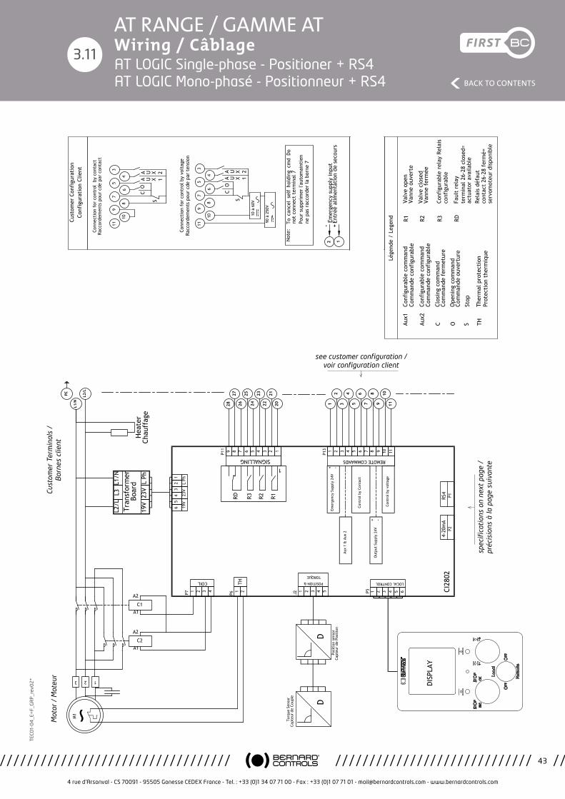
4 rue d’Arsonval - CS 70091 - 95505 Gonesse CEDEX France - Tel. : +33 (0)1 34 07 71 00 - Fax : +33 (0)1 07 71 01 - [email protected] - www.bernardcontrols.com
43
BACK TO CONTENTS
TEC
01-
04
_E+
F_G
RP
_rev
02
*AT RANGE / GAMME AT Wiring / Câblage
Emer
genc
y Su
pply
24V
Etud
e/St
udy:
Ind.
/Rev
.:PR
OD
Plan
che/
Shee
t:
Proj
et/P
roje
ct:
Mod
ific
atio
n:
Appr
ouvé
/App
rove
dAp
prou
vé/A
ppro
ved
Dess
iné
par:
Desi
gned
by:
Véri
fié
par:
Chec
ked
by:
Valid
é pa
r:Va
lidat
ed b
y:PR
OTO
Ce p
lan
étan
t no
tre
prop
riété
, il n
e pe
ut ê
tre
repr
odui
t ou
com
mun
iqué
san
s no
tre
auto
risat
ion
écrit
e.Th
is dr
awin
g is
our p
rope
rty
and
may
not
be
repr
oduc
ed o
r com
mun
icat
ed w
ithou
t ou
r writ
ten
auth
oriz
atio
n.
4 ru
e d'
Arso
nval
BP
91
9550
5 G
ON
ESSE
CED
EX
ww
w.b
erna
rdco
ntro
ls.c
om
PBCD
T160
10
E
DM17
374
AT/A
Q-2
5 à
50
MO
NO
PHAS
EE
LOG
IC
SIN
GLE
PH
ASE
AT/A
Q-2
5 to
50
LOG
IC
WD_
6300
24_F
REN
Posi
tion
neur
, RS
4
Posi
tion
er,
RS4
18/1
2/17
L.M
aiss
in
05/1
2/17
Mon
tagn
er
05/1
2/17
->->M
.Wol
osz
S.Da
dier
21
/12/
17
9
10
11
Lége
nde
/ Le
gend
CAux1
CO
6
7
8
3
4
5
10 à
60V
S
Conn
ecti
on f
or c
ontr
ol b
y vo
ltag
e Ra
ccor
dem
ents
pou
r cd
e pa
r te
nsio
n
90 à
250
V
Not
e:
SOAux2
To c
ance
l se
lf h
oldi
ng c
md
Do
not
conn
ect
term
inal
7Po
ur s
uppr
imer
l'au
tom
aint
ien
ne p
as r
acco
rder
la b
orne
7
TH
Conn
ecti
on f
or c
ontr
ol b
y co
ntac
t Ra
ccor
dem
ents
pou
r cd
e pa
r co
ntac
t
CO
S
2827
4 3 2 19 8 7
SIGNALLING
R1R3 R2RD
1
P11 6 5
2625
2423
2221
20
LOCAL CONTROL
8 9 10 113 4 5
REMOTE COMMANDS
P13 6 7
34
56
78
910
11
1 2 3 4 5 6
1 21
2
321
COIL
3 4 51 2J2Ca
pteu
r de
Cou
ple
Capt
eur
de P
osit
ion
Torq
ue S
enso
r
Posi
tion
sen
sor
11
10
9
8
7
6
5
4
3
P7 P51 2TH
P6
65
43
21
19V
23V
L Ph
4-20
mA
P2
Cont
rol b
y vo
ltag
e
Out
put
Supp
ly 2
4V
Cont
rol b
y Co
ntac
t
Aux
1 &
Aux
2
CI28
02
-
-
+
+
RS4
P1
4
DD
R2R1
12Em
erge
ncy
supp
ly in
put
RDR3
+En
trée
alim
enta
tion
de
seco
urs
-
Cust
omer
Con
figu
rati
on
Conf
igur
atio
n Cl
ient
POSITION &
TORQUE
U X 1AA U X 2
U X 1AA U X 2
Valv
e op
enVa
nne
ouve
rte
Valv
e cl
osed
Vann
e fe
rmée
Conf
igur
able
rel
ay R
elai
s co
nfig
urab
le
Faul
t re
lay
term
inal
26-
28 c
lose
d=
actu
ator
ava
ilabl
eRe
lais
déf
aut
cont
act
26-2
8 fe
rmé=
se
rvom
oteu
r di
spon
ible
Conf
igur
able
com
man
d Co
mm
ande
con
figu
rabl
e
Conf
igur
able
com
man
d Co
mm
ande
con
figu
rabl
e
Clos
ing
com
man
d Co
mm
ande
fer
met
ure
Ope
ning
com
man
d Co
mm
ande
ouv
ertu
re
Stop
Ther
mal
pro
tect
ion
Prot
ecti
on t
herm
ique
13 2
M1
C2A1
A2
C1A1
A2
L2/L
L3L1
/N
Tran
sfor
mer
Bo
ard
19V
23V
L Ph
PE
L1/N
L2/L
DISP
LAY
Hea
ter
Chau
ffag
e
3.11AT LOGIC Single-phase - Positioner + RS4 AT LOGIC Mono-phasé - Positionneur + RS4
spec
ifica
tion
s on
nex
t pa
ge /
pr
écis
ions
à la
pag
e su
ivan
te
see customer configuration / voir configuration client
Mot
or /
Mot
eur
Cust
omer
Ter
min
als
/
Bor
nes
clie
nt
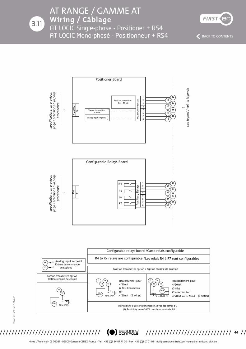
4 rue d’Arsonval - CS 70091 - 95505 Gonesse CEDEX France - Tel. : +33 (0)1 34 07 71 00 - Fax : +33 (0)1 07 71 01 - [email protected] - www.bernardcontrols.com
44
BACK TO CONTENTS
TEC
01-
04
_E+
F_G
RP
_rev
02
*AT RANGE / GAMME AT Wiring / Câblage
3.11
Etude/Study:
Ind./Rev.:PROD
Planche/Sheet:
Projet/Project: Modification:
Approuvé/Approved Approuvé/ApprovedDessiné par:Designed by:
Vérifié par:Checked by:
Validé par:Validated by: PROTO
Ce plan étant notre propriété, il ne peut être reproduit ou communiqué sans notre autorisation écrite.This drawing is our property and may not be reproduced or communicated without our written authorization.
4 rue d'Arsonval BP 91 95505 GONESSE CEDEX
www.bernardcontrols.com
PBCDT16010
E
DM17374
AT/AQ-25 à 50 MONOPHASEE LOGIC SINGLE PHASE AT/AQ-25 to 50 LOGIC
WD_630024_FREN
Positionneur, RS4
Positioner, RS4
18/12/17
L.Maissin
05/12/17
Montagner
05/12/17 ->->M.Wolosz S.Dadier
21/12/17
4-20
mA
P2
1314
1516
1718
19
5678
234
Torque transmitter
Position transmitter
Analog input setpoint ANA
IN/O
UT
Inte
rfac
e
1 12
4-20mA
0/4 - 20 mA
RS4
P1
3031
3233
3435
36
29
Auxi
liary
Rel
ays
R7
R5
R6
Configurable Relays Board
R4
5678
1234
(1) Possibilité d'utiliser l'alimentation 24 Vcc des bornes 8-9
(1) Possibility to use 24 Vdc supply on terminals 8-9
12 to 32VDCmA (1)
Raccordement pour 4/20mA(2 fils) Connection for 4/20mA (2 wires)
12
13
14
15
12 to 32VDC (1)
Raccordement pour 4/20mA(3 fils)Connection for 4/20mA ou 0/20mA
mA
12
13
14
15
(3 wires)
Position transmitter option / Option recopie de position
12 to 32VDCmA (1)
16
17
19
18
-
+ Analog input setpoint
Torque transmitter option Option recopie de couple
+
-
-
+
Positioner Board
Configurable relays board /Carte relais configurable
R4 to R7 relays are configurable /Les relais R4 à R7 sont configurables
Entrée de commande analogique
see
lege
nd /
voi
r la
lége
nde
spec
ifica
tion
s on
pre
viou
s pa
ge /
pré
cisi
ons
à la
pag
e pr
écéd
ente
spec
ifica
tion
s on
pre
viou
s pa
ge /
pré
cisi
ons
à la
pag
e pr
écéd
ente
AT LOGIC Single-phase - Positioner + RS4 AT LOGIC Mono-phasé - Positionneur + RS4

4 rue d’Arsonval - CS 70091 - 95505 Gonesse CEDEX France - Tel. : +33 (0)1 34 07 71 00 - Fax : +33 (0)1 07 71 01 - [email protected] - www.bernardcontrols.com
45
BACK TO CONTENTS
TEC
01-
04
_E+
F_G
RP
_rev
02
*AT RANGE / GAMME AT Wiring / Câblage
3.12AT LOGIC 3-phases - Positioner + RS4 AT LOGIC Triphasé - Positionneur + RS4
Emer
genc
y Su
pply
24V
Etud
e/St
udy:
Ind.
/Rev
.:PR
OD
Plan
che/
Shee
t:
Proj
et/P
roje
ct:
Mod
ific
atio
n:
Appr
ouvé
/App
rove
dAp
prou
vé/A
ppro
ved
Dess
iné
par:
Desi
gned
by:
Véri
fié
par:
Chec
ked
by:
Valid
é pa
r:Va
lidat
ed b
y:PR
OTO
Ce p
lan
étan
t no
tre
prop
riété
, il n
e pe
ut ê
tre
repr
odui
t ou
com
mun
iqué
san
s no
tre
auto
risat
ion
écrit
e.Th
is dr
awin
g is
our p
rope
rty
and
may
not
be
repr
oduc
ed o
r com
mun
icat
ed w
ithou
t ou
r writ
ten
auth
oriz
atio
n.
4 ru
e d'
Arso
nval
BP
91
9550
5 G
ON
ESSE
CED
EX
ww
w.b
erna
rdco
ntro
ls.c
om
PBCD
T160
10
D
DM17
374
AT/A
Q-2
5 à
50 T
RIPH
ASEE
LO
GIC
TH
REE
PHAS
E AT
/AQ
-25
to 5
0 LO
GIC
WD_
6300
25_F
REN
Posi
tion
neur
, RS
4
Posi
tion
er,
RS4
18/1
2/17
L.M
aiss
in
05/1
2/17
Mon
tagn
er
05/1
2/17
->->M
.Wol
osz
S.Da
dier
21
/12/
17
9
10
11
Lége
nde
/ Le
gend
CAux1
CO
6
7
8
3
4
5
10 à
60V
S
Conn
ecti
on f
or c
ontr
ol b
y vo
ltag
e Ra
ccor
dem
ents
pou
r cd
e pa
r te
nsio
n
90 à
250
V
Not
e:
SOAux2
To c
ance
l se
lf h
oldi
ng c
md
Do
not
conn
ect
term
inal
7Po
ur s
uppr
imer
l'au
tom
aint
ien
ne p
as r
acco
rder
la b
orne
7
TH
Conn
ecti
on f
or c
ontr
ol b
y co
ntac
t Ra
ccor
dem
ents
pou
r cd
e pa
r co
ntac
t
CO
S
2827
4 3 2 19 8 7
SIGNALLING
R1R3 R2RD
1
P11 6 5
2625
2423
2221
20
LOCAL CONTROL
8 9 10 113 4 5
REMOTE COMMANDS
P13 6 7
34
56
78
910
11
1 2 3 4 5 6
1 21
2
321
COIL
3 4 51 2J2Ca
pteu
r de
Cou
ple
Capt
eur
de P
osit
ion
Torq
ue S
enso
r
Posi
tion
sen
sor
11
10
9
8
7
6
5
4
3
P7 P51 2TH
P6
65
43
21
19V
23V
L Ph
4-20
mA
P2
Cont
rol b
y vo
ltag
e
Out
put
Supp
ly 2
4V
Cont
rol b
y Co
ntac
t
Aux
1 &
Aux
2
CI28
02
-
-
+
+
RS4
P1
4
DD
R2R1
12Em
erge
ncy
supp
ly in
put
RDR3
+En
trée
alim
enta
tion
de
seco
urs
-
Cust
omer
Con
figu
rati
on
Conf
igur
atio
n Cl
ient
POSITION &
TORQUE
U X 1AA U X 2
U X 1AA U X 2
Conf
igur
able
com
man
d Co
mm
ande
con
figu
rabl
e
Conf
igur
able
com
man
d Co
mm
ande
con
figu
rabl
e
Clos
ing
com
man
d Co
mm
ande
fer
met
ure
Ope
ning
com
man
d Co
mm
ande
ouv
ertu
re
Stop
Ther
mal
pro
tect
ion
Prot
ecti
on t
herm
ique
L2/L
L3L1
/N
Tran
sfor
mer
Bo
ard
19V
23V
L Ph
13 2
M3
C2A1
A2
C1A1
A2
The
phas
e se
quen
cy is
not
impo
rtan
t If
one
pha
se is
mis
sing
, th
e ac
tuat
or w
ill n
ot s
tart
and
se
nds
an a
larm
(Fa
ult
rela
y).
L'or
dre
des
phas
es n
'a p
as d
'impo
rtan
ce.
Si l'
une
d'el
les
est
man
quan
te,
le s
ervo
mot
eur
ne
redé
mar
re p
as e
t si
gnal
e le
déf
aut
(Rel
ais
défa
ut).
PE
L1/N
L2/L
L3
DISP
LAY
Hea
ter
Chau
ffag
e
Valv
e op
enVa
nne
ouve
rte
Valv
e cl
osed
Vann
e fe
rmée
Conf
igur
able
rel
ay R
elai
s co
nfig
urab
le
Faul
t re
lay
term
inal
26-
28 c
lose
d=
actu
ator
ava
ilabl
eRe
lais
déf
aut
cont
act
26-2
8 fe
rmé=
se
rvom
oteu
r di
spon
ible
spec
ifica
tion
s on
nex
t pa
ge /
pr
écis
ions
à la
pag
e su
ivan
te
The
pha
se s
eque
ncy
is n
ot im
port
ant
if o
ne p
hase
is m
issi
ng, t
he a
ctua
tor
will
not
sta
rt a
nd s
ends
an
alar
m (
Faul
t re
lay)
. L’
ordr
e de
s ph
ases
n’a
pas
d’im
port
ance
. Si l
’une
d’e
lles
est
man
quan
te, l
e se
rvom
oteu
r ne
red
émar
re p
as e
t si
gnal
e le
déf
aut
(Rel
ais
défa
ut)
see customer configuration / voir configuration client
Mot
or /
Mot
eur
Cust
omer
Ter
min
als
/
Bor
nes
clie
nt
Emergency Supply 24V
Etude/Study:
Ind./Rev.:PROD
Planche/Sheet:
Projet/Project: Modification:
Approuvé/Approved Approuvé/ApprovedDessiné par:Designed by:
Vérifié par:Checked by:
Validé par:Validated by: PROTO
Ce plan étant notre propriété, il ne peut être reproduit ou communiqué sans notre autorisation écrite.This drawing is our property and may not be reproduced or communicated without our written authorization.
4 rue d'Arsonval BP 91 95505 GONESSE CEDEX
www.bernardcontrols.com
PBCDT16010
D
DM17374
AT/AQ-25 à 50 TRIPHASEE LOGIC THREE PHASE AT/AQ-25 to 50 LOGIC
WD_630025_FREN
Positionneur, RS4
Positioner, RS4
18/12/17
L.Maissin
05/12/17
Montagner
05/12/17 ->->M.Wolosz S.Dadier
21/12/17
9
10
11
Légende / Legend
C
Aux1
C O
6
7
8
3
4
5
10 à 60V
S
Connection for control by voltage Raccordements pour cde par tension
90 à 250V
Note:
S
O
Aux2
To cancel self holding cmd Do not connect terminal 7Pour supprimer l'automaintien ne pas raccorder la borne 7
TH
Connection for control by contact Raccordements pour cde par contact
C O
S
2827
4321
987
SIG
NAL
LIN
G
R1
R3
R2
RD
1
P11
65
2625
2423
2221
20
LOCA
L CO
NTR
OL
891011
345
REM
OTE
CO
MM
ANDS
P13
67
34
56
78
910
11
123456
12
12
321
COIL
345
12
J2Capteur de Couple
Capteur de Position
Torque Sensor
Position sensor
11
10
9
8
7
6
5
4
3
P7
P5
12 TH
P6
6 5 4 3 2 1
19V 23V L Ph
4-20mAP2
Control by voltage
Output Supply 24V
Control by Contact
Aux 1 & Aux 2
CI2802
-
-
+
+
RS4P1
4
DD
R2
R1
1
2 Emergency supply input
RD
R3
+ Entrée alimentation de secours
-
Customer Configuration Configuration Client
POSI
TIO
N &
TORQ
UE
UX1
A AUX2
UX1
A AUX2
Configurable command Commande configurable
Configurable command Commande configurable
Closing command Commande fermeture
Opening command Commande ouverture
Stop
Thermal protection Protection thermique
L2/L L3 L1/N
Transformer Board
19V 23V L Ph1
32
M3
C2A1
A2 C1A1
A2The phase sequency is not important If one phase is missing, the actuator will not start and sends an alarm (Fault relay).
L'ordre des phases n'a pas d'importance.Si l'une d'elles est manquante, le servomoteur ne redémarre pas et signale le défaut (Relais défaut).
PE
L1/N
L2/L
L3
DISPLAY
Heater Chauffage
Valve openVanne ouverte
Valve closedVanne fermée
Configurable relay Relais configurable
Fault relayterminal 26-28 closed= actuator availableRelais défautcontact 26-28 fermé= servomoteur disponible
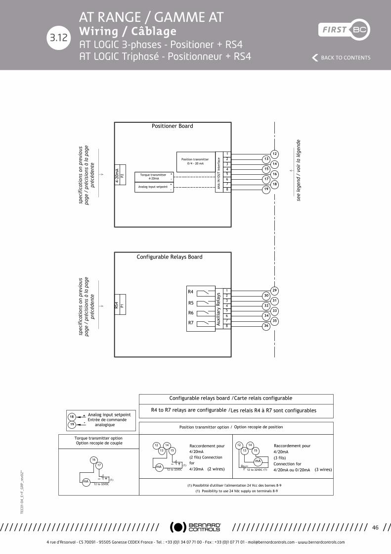
4 rue d’Arsonval - CS 70091 - 95505 Gonesse CEDEX France - Tel. : +33 (0)1 34 07 71 00 - Fax : +33 (0)1 07 71 01 - [email protected] - www.bernardcontrols.com
46
BACK TO CONTENTS
TEC
01-
04
_E+
F_G
RP
_rev
02
*AT RANGE / GAMME AT Wiring / Câblage
3.12
Etude/Study:
Ind./Rev.:PROD
Planche/Sheet:
Projet/Project: Modification:
Approuvé/Approved Approuvé/ApprovedDessiné par:Designed by:
Vérifié par:Checked by:
Validé par:Validated by: PROTO
Ce plan étant notre propriété, il ne peut être reproduit ou communiqué sans notre autorisation écrite.This drawing is our property and may not be reproduced or communicated without our written authorization.
4 rue d'Arsonval BP 91 95505 GONESSE CEDEX
www.bernardcontrols.com
PBCDT16010
D
DM17374
AT/AQ-25 à 50 TRIPHASEE LOGIC THREE PHASE AT/AQ-25 to 50 LOGIC
WD_630025_FREN
Positionneur, RS4
Positioner, RS4
18/12/17
L.Maissin
05/12/17
Montagner
05/12/17 ->->M.Wolosz S.Dadier
21/12/17
4-20
mA
P2
1314
1516
1718
19
5678
234
Torque transmitter
Position transmitter
Analog input setpoint ANA
IN/O
UT
Inte
rfac
e
1 12
4-20mA
0/4 - 20 mA
RS4
P1
3031
3233
3435
36
29
Auxi
liary
Rel
ays
R7
R5
R6
Configurable Relays Board
R4
5678
1234
(1) Possibilité d'utiliser l'alimentation 24 Vcc des bornes 8-9
(1) Possibility to use 24 Vdc supply on terminals 8-9
12 to 32VDCmA (1)
Raccordement pour 4/20mA(2 fils) Connection for 4/20mA (2 wires)
12
13
14
15
12 to 32VDC (1)
Raccordement pour 4/20mA(3 fils)Connection for 4/20mA ou 0/20mA
mA
12
13
14
15
(3 wires)
Position transmitter option / Option recopie de position
12 to 32VDCmA (1)
16
17
19
18
-
+ Analog input setpoint
Torque transmitter option Option recopie de couple
+
-
-
+
Positioner Board
Configurable relays board /Carte relais configurable
R4 to R7 relays are configurable /Les relais R4 à R7 sont configurables
Entrée de commande analogique
see
lege
nd /
voi
r la
lége
nde
spec
ifica
tion
s on
pre
viou
s pa
ge /
pré
cisi
ons
à la
pag
e pr
écéd
ente
spec
ifica
tion
s on
pre
viou
s pa
ge /
pré
cisi
ons
à la
pag
e pr
écéd
ente
AT LOGIC 3-phases - Positioner + RS4 AT LOGIC Triphasé - Positionneur + RS4

4 rue d’Arsonval - CS 70091 - 95505 Gonesse CEDEX France - Tel. : +33 (0)1 34 07 71 00 - Fax : +33 (0)1 07 71 01 - [email protected] - www.bernardcontrols.com
47
BACK TO CONTENTS
TEC
01-
04
_E+
F_G
RP
_rev
02
*AT RANGE / GAMME AT Wiring / Câblage
3.13
Emer
genc
y Su
pply
24V
Etud
e/St
udy:
Ind.
/Rev
.:PR
OD
Plan
che/
Shee
t:
Proj
et/P
roje
ct:
Mod
ific
atio
n:
Appr
ouvé
/App
rove
dAp
prou
vé/A
ppro
ved
Dess
iné
par:
Desi
gned
by:
Véri
fié
par:
Chec
ked
by:
Valid
é pa
r:Va
lidat
ed b
y:PR
OTO
Ce p
lan
étan
t no
tre
prop
riété
, il n
e pe
ut ê
tre
repr
odui
t ou
com
mun
iqué
san
s no
tre
auto
risat
ion
écrit
e.Th
is dr
awin
g is
our p
rope
rty
and
may
not
be
repr
oduc
ed o
r com
mun
icat
ed w
ithou
t ou
r writ
ten
auth
oriz
atio
n.
4 ru
e d'
Arso
nval
BP
91
9550
5 G
ON
ESSE
CED
EX
ww
w.b
erna
rdco
ntro
ls.c
om
PBCD
T160
10
D
DM17
374
AT/A
Q-2
5 à
50
MO
NO
PHAS
EE
LOG
IC
SIN
GLE
PH
ASE
AT/A
Q-2
5 to
50
LOG
IC
WD_
6300
26_F
REN
Tran
smit
teur
, RS
4
Tran
smit
ter,
RS4
18/1
2/17
L.M
aiss
in
05/1
2/17
Mon
tagn
er
05/1
2/17
->->M
.Wol
osz
S.Da
dier
21
/12/
17
9
10
11
Lége
nde
/ Le
gend
CAux1
CO
6
7
8
3
4
5
10 à
60V
S
Conn
ecti
on f
or c
ontr
ol b
y vo
ltag
e Ra
ccor
dem
ents
pou
r cd
e pa
r te
nsio
n
90 à
250
V
Not
e:
SOAux2
To c
ance
l se
lf h
oldi
ng c
md
Do
not
conn
ect
term
inal
7Po
ur s
uppr
imer
l'au
tom
aint
ien
ne p
as r
acco
rder
la b
orne
7
TH
Conn
ecti
on f
or c
ontr
ol b
y co
ntac
t Ra
ccor
dem
ents
pou
r cd
e pa
r co
ntac
t
CO
S
2827
4 3 2 19 8 7
SIGNALLING
R1R3 R2RD
1
P11 6 5
2625
2423
2221
20
LOCAL CONTROL
8 9 10 113 4 5
REMOTE COMMANDS
P13 6 7
34
56
78
910
11
1 2 3 4 5 6
1 21
2
321
COIL
3 4 51 2J2Ca
pteu
r de
Cou
ple
Capt
eur
de P
osit
ion
Torq
ue S
enso
r
Posi
tion
sen
sor
11
10
9
8
7
6
5
4
3
P7 P51 2TH
P6
65
43
21
19V
23V
L Ph
Cont
rol b
y vo
ltag
e
Out
put
Supp
ly 2
4V
Cont
rol b
y Co
ntac
t
Aux
1 &
Aux
2
CI28
02
-
-
+
+
RS4
P1
4
DD
R2R1
12Em
erge
ncy
supp
ly in
put
RDR3
+En
trée
alim
enta
tion
de
seco
urs
-
Cust
omer
Con
figu
rati
on
Conf
igur
atio
n Cl
ient
POSITION &
TORQUE
U X 1AA U X 2
U X 1AA U X 2
Conf
igur
able
com
man
d Co
mm
ande
con
figu
rabl
e
Conf
igur
able
com
man
d Co
mm
ande
con
figu
rabl
e
Clos
ing
com
man
d Co
mm
ande
fer
met
ure
Ope
ning
com
man
d Co
mm
ande
ouv
ertu
re
Stop
Ther
mal
pro
tect
ion
Prot
ecti
on t
herm
ique
13 2
M1
C2A1
A2
C1A1
A2
L2/L
L3L1
/N
Tran
sfor
mer
Bo
ard
19V
23V
L Ph
PE
L1/N
L2/L
4-20
mA
P2
DISP
LAY
Hea
ter
Chau
ffag
e
Valv
e op
enVa
nne
ouve
rte
Valv
e cl
osed
Vann
e fe
rmée
Conf
igur
able
rel
ay R
elai
s co
nfig
urab
le
Faul
t re
lay
term
inal
26-
28 c
lose
d=
actu
ator
ava
ilabl
eRe
lais
déf
aut
cont
act
26-2
8 fe
rmé=
se
rvom
oteu
r di
spon
ible
spec
ifica
tion
s on
nex
t pa
ge /
pr
écis
ions
à la
pag
e su
ivan
te
see customer configuration / voir configuration client
Mot
or /
Mot
eur
Cust
omer
Ter
min
als
/
Bor
nes
clie
ntAT LOGIC Single-phase - Transmitter + RS4 AT LOGIC Mono-phasé - Transmetteur + RS4
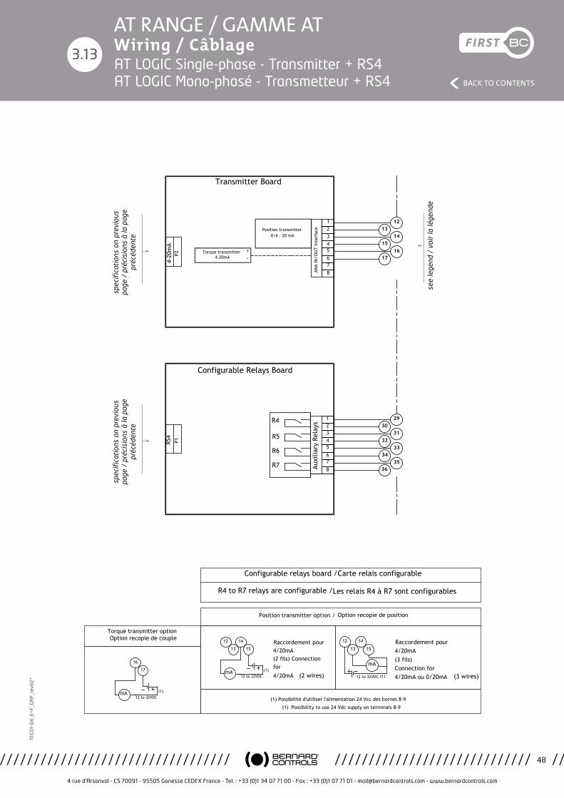
4 rue d’Arsonval - CS 70091 - 95505 Gonesse CEDEX France - Tel. : +33 (0)1 34 07 71 00 - Fax : +33 (0)1 07 71 01 - [email protected] - www.bernardcontrols.com
48
BACK TO CONTENTS
TEC
01-
04
_E+
F_G
RP
_rev
02
*AT RANGE / GAMME AT Wiring / Câblage
3.13
Etude/Study:
Ind./Rev.:PROD
Planche/Sheet:
Projet/Project: Modification:
Approuvé/Approved Approuvé/ApprovedDessiné par:Designed by:
Vérifié par:Checked by:
Validé par:Validated by: PROTO
Ce plan étant notre propriété, il ne peut être reproduit ou communiqué sans notre autorisation écrite.This drawing is our property and may not be reproduced or communicated without our written authorization.
4 rue d'Arsonval BP 91 95505 GONESSE CEDEX
www.bernardcontrols.com
PBCDT16010
D
DM17374
AT/AQ-25 à 50 MONOPHASEE LOGIC SINGLE PHASE AT/AQ-25 to 50 LOGIC
WD_630026_FREN
Transmitteur, RS4
Transmitter, RS4
18/12/17
L.Maissin
05/12/17
Montagner
05/12/17 ->->M.Wolosz S.Dadier
21/12/17
RS4
P1
3031
3233
3435
36
29
Auxi
liary
Rel
ays
R7
R5
R6
Configurable Relays Board
R4
5678
1234
Configurable relays board /Carte relais configurable
R4 to R7 relays are configurable /Les relais R4 à R7 sont configurables
4-20
mA
P2
13
15
175678
234
Torque transmitter
Position transmitter
ANA
IN/O
UT
Inte
rfac
e
1
4-20mA
0/4 - 20 mA
+
-
Transmitter Board
14
16
12
(1) Possibilité d'utiliser l'alimentation 24 Vcc des bornes 8-9
(1) Possibility to use 24 Vdc supply on terminals 8-9
12 to 32VDCmA (1)
Raccordement pour 4/20mA(2 fils) Connection for 4/20mA (2 wires)
12
13
14
15
12 to 32VDC (1)
Raccordement pour 4/20mA(3 fils)Connection for 4/20mA ou 0/20mA
mA
12
13
14
15
(3 wires)
Position transmitter option / Option recopie de position
12 to 32VDCmA (1)
16
17
Torque transmitter option Option recopie de couple
see
lege
nd /
voi
r la
lége
nde
spec
ifica
tion
s on
pre
viou
s pa
ge /
pré
cisi
ons
à la
pag
e pr
écéd
ente
spec
ifica
tion
s on
pre
viou
s pa
ge /
pré
cisi
ons
à la
pag
e pr
écéd
ente
AT LOGIC Single-phase - Transmitter + RS4 AT LOGIC Mono-phasé - Transmetteur + RS4

4 rue d’Arsonval - CS 70091 - 95505 Gonesse CEDEX France - Tel. : +33 (0)1 34 07 71 00 - Fax : +33 (0)1 07 71 01 - [email protected] - www.bernardcontrols.com
49
BACK TO CONTENTS
TEC
01-
04
_E+
F_G
RP
_rev
02
*AT RANGE / GAMME AT Wiring / Câblage
3.14
Emer
genc
y Su
pply
24V
Etud
e/St
udy:
Ind.
/Rev
.:PR
OD
Plan
che/
Shee
t:
Proj
et/P
roje
ct:
Mod
ific
atio
n:
Appr
ouvé
/App
rove
dAp
prou
vé/A
ppro
ved
Dess
iné
par:
Desi
gned
by:
Véri
fié
par:
Chec
ked
by:
Valid
é pa
r:Va
lidat
ed b
y:PR
OTO
Ce p
lan
étan
t no
tre
prop
riété
, il n
e pe
ut ê
tre
repr
odui
t ou
com
mun
iqué
san
s no
tre
auto
risat
ion
écrit
e.Th
is dr
awin
g is
our p
rope
rty
and
may
not
be
repr
oduc
ed o
r com
mun
icat
ed w
ithou
t ou
r writ
ten
auth
oriz
atio
n.
4 ru
e d'
Arso
nval
BP
91
9550
5 G
ON
ESSE
CED
EX
ww
w.b
erna
rdco
ntro
ls.c
om
PCBD
T160
10
D
DM17
374
AT/A
Q-2
5 à
50 T
RIPH
ASEE
LO
GIC
TH
REE
PHAS
E AT
/AQ
-25
to 5
0 LO
GIC
WD_
6300
27_F
REN
Tran
smit
teur
, RS
4
Tran
smit
ter,
RS4
18/1
2/17
L.M
aiss
in
05/1
2/17
Mon
tagn
er
05/1
2/17
->->M
.Wol
osz
S.Da
dier
21
/12/
17
9
10
11
Lége
nde
/ Le
gend
CAux1
CO
6
7
8
3
4
5
10 à
60V
S
Conn
ecti
on f
or c
ontr
ol b
y vo
ltag
e Ra
ccor
dem
ents
pou
r cd
e pa
r te
nsio
n
90 à
250
V
Not
e:
SOAux2
To c
ance
l se
lf h
oldi
ng c
md
Do
not
conn
ect
term
inal
7Po
ur s
uppr
imer
l'au
tom
aint
ien
ne p
as r
acco
rder
la b
orne
7
TH
Conn
ecti
on f
or c
ontr
ol b
y co
ntac
t Ra
ccor
dem
ents
pou
r cd
e pa
r co
ntac
t
CO
S
2827
4 3 2 19 8 7
SIGNALLING
R1R3 R2RD
1
P11 6 5
2625
2423
2221
20
LOCAL CONTROL
8 9 10 113 4 5
REMOTE COMMANDS
P13 6 7
34
56
78
910
11
1 2 3 4 5 6
1 21
2
321
COIL
3 4 51 2J2Ca
pteu
r de
Cou
ple
Capt
eur
de P
osit
ion
Torq
ue S
enso
r
Posi
tion
sen
sor
11
10
9
8
7
6
5
4
3
P7 P51 2TH
P6
65
43
21
19V
23V
L Ph
Cont
rol b
y vo
ltag
e
Out
put
Supp
ly 2
4V
Cont
rol b
y Co
ntac
t
Aux
1 &
Aux
2
CI28
02
-
-
+
+
RS4
P1
4
DD
R2R1
12Em
erge
ncy
supp
ly in
put
RDR3
+En
trée
alim
enta
tion
de
seco
urs
-
Cust
omer
Con
figu
rati
on
Conf
igur
atio
n Cl
ient
POSITION &
TORQUE
U X 1AA U X 2
U X 1AA U X 2
Conf
igur
able
com
man
d Co
mm
ande
con
figu
rabl
e
Conf
igur
able
com
man
d Co
mm
ande
con
figu
rabl
e
Clos
ing
com
man
d Co
mm
ande
fer
met
ure
Ope
ning
com
man
d Co
mm
ande
ouv
ertu
re
Stop
Ther
mal
pro
tect
ion
Prot
ecti
on t
herm
ique
L2/L
L3L1
/N
Tran
sfor
mer
Bo
ard
19V
23V
L Ph
13 2
M3
C2A1
A2
C1A1
A2
The
phas
e se
quen
cy is
not
impo
rtan
t If
one
pha
se is
mis
sing
, th
e ac
tuat
or w
ill n
ot s
tart
and
se
nds
an a
larm
(Fa
ult
rela
y).
L'or
dre
des
phas
es n
'a p
as d
'impo
rtan
ce.
Si l'
une
d'el
les
est
man
quan
te,
le s
ervo
mot
eur
ne
redé
mar
re p
as e
t si
gnal
e le
déf
aut
(Rel
ais
défa
ut).
PE
L1/N
L2/L
L3
4-20
mA
P2
DISP
LAY
Hea
ter
Chau
ffag
e
Valv
e op
enVa
nne
ouve
rte
Valv
e cl
osed
Vann
e fe
rmée
Conf
igur
able
rel
ay R
elai
s co
nfig
urab
le
Faul
t re
lay
term
inal
26-
28 c
lose
d=
actu
ator
ava
ilabl
eRe
lais
déf
aut
cont
act
26-2
8 fe
rmé=
se
rvom
oteu
r di
spon
ible
spec
ifica
tion
s on
nex
t pa
ge /
pr
écis
ions
à la
pag
e su
ivan
te
see customer configuration / voir configuration client
Mot
or /
Mot
eur
Cust
omer
Ter
min
als
/
Bor
nes
clie
nt
The
pha
se s
eque
ncy
is n
ot im
port
ant
if o
ne p
hase
is m
issi
ng, t
he a
ctua
tor
will
not
sta
rt a
nd s
ends
an
alar
m (
Faul
t re
lay)
. L’
ordr
e de
s ph
ases
n’a
pas
d’im
port
ance
. Si l
’une
d’e
lles
est
man
quan
te, l
e se
rvom
oteu
r ne
red
émar
re p
as e
t si
gnal
e le
déf
aut
(Rel
ais
défa
ut)
Emergency Supply 24V
Etude/Study:
Ind./Rev.:PROD
Planche/Sheet:
Projet/Project: Modification:
Approuvé/Approved Approuvé/ApprovedDessiné par:Designed by:
Vérifié par:Checked by:
Validé par:Validated by: PROTO
Ce plan étant notre propriété, il ne peut être reproduit ou communiqué sans notre autorisation écrite.This drawing is our property and may not be reproduced or communicated without our written authorization.
4 rue d'Arsonval BP 91 95505 GONESSE CEDEX
www.bernardcontrols.com
PCBDT16010
D
DM17374
AT/AQ-25 à 50 TRIPHASEE LOGIC THREE PHASE AT/AQ-25 to 50 LOGIC
WD_630027_FREN
Transmitteur, RS4
Transmitter, RS4
18/12/17
L.Maissin
05/12/17
Montagner
05/12/17 ->->M.Wolosz S.Dadier
21/12/17
9
10
11
Légende / Legend
C
Aux1
C O
6
7
8
3
4
5
10 à 60V
S
Connection for control by voltage Raccordements pour cde par tension
90 à 250V
Note:
S
O
Aux2
To cancel self holding cmd Do not connect terminal 7Pour supprimer l'automaintien ne pas raccorder la borne 7
TH
Connection for control by contact Raccordements pour cde par contact
C O
S
2827
4321
987
SIG
NAL
LIN
G
R1
R3
R2
RD
1
P11
65
2625
2423
2221
20
LOCA
L CO
NTR
OL
891011
345
REM
OTE
CO
MM
ANDS
P13
67
34
56
78
910
11
123456
12
12
321
COIL
345
12
J2Capteur de Couple
Capteur de Position
Torque Sensor
Position sensor
11
10
9
8
7
6
5
4
3
P7
P5
12 TH
P6
6 5 4 3 2 1
19V 23V L Ph
Control by voltage
Output Supply 24V
Control by Contact
Aux 1 & Aux 2
CI2802
-
-
+
+
RS4P1
4
DD
R2
R1
1
2 Emergency supply input
RD
R3
+ Entrée alimentation de secours
-
Customer Configuration Configuration Client
POSI
TIO
N &
TORQ
UE
UX1
A AUX2
UX1
A AUX2
Configurable command Commande configurable
Configurable command Commande configurable
Closing command Commande fermeture
Opening command Commande ouverture
Stop
Thermal protection Protection thermique
L2/L L3 L1/N
Transformer Board
19V 23V L Ph1
32
M3
C2A1
A2 C1A1
A2The phase sequency is not important If one phase is missing, the actuator will not start and sends an alarm (Fault relay).
L'ordre des phases n'a pas d'importance.Si l'une d'elles est manquante, le servomoteur ne redémarre pas et signale le défaut (Relais défaut).
PE
L1/N
L2/L
L3
4-20mAP2
DISPLAY
Heater Chauffage
Valve openVanne ouverte
Valve closedVanne fermée
Configurable relay Relais configurable
Fault relayterminal 26-28 closed= actuator availableRelais défautcontact 26-28 fermé= servomoteur disponible
AT LOGIC 3-phases - Transmitter + RS4 AT LOGIC Triphasé - Transmetteur + RS4
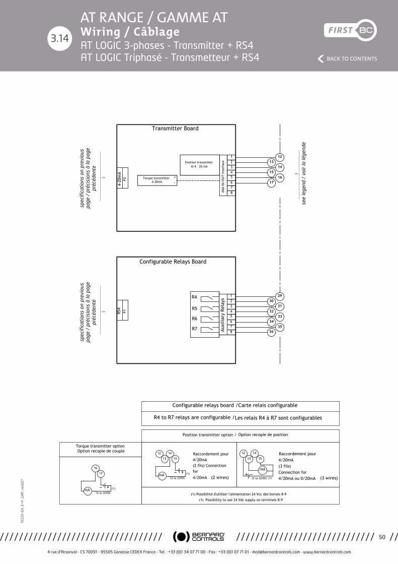
4 rue d’Arsonval - CS 70091 - 95505 Gonesse CEDEX France - Tel. : +33 (0)1 34 07 71 00 - Fax : +33 (0)1 07 71 01 - [email protected] - www.bernardcontrols.com
50
BACK TO CONTENTS
TEC
01-
04
_E+
F_G
RP
_rev
02
*AT RANGE / GAMME AT Wiring / Câblage
3.14
Etude/Study:
Ind./Rev.:PROD
Planche/Sheet:
Projet/Project: Modification:
Approuvé/Approved Approuvé/ApprovedDessiné par:Designed by:
Vérifié par:Checked by:
Validé par:Validated by: PROTO
Ce plan étant notre propriété, il ne peut être reproduit ou communiqué sans notre autorisation écrite.This drawing is our property and may not be reproduced or communicated without our written authorization.
4 rue d'Arsonval BP 91 95505 GONESSE CEDEX
www.bernardcontrols.com
PCBDT16010
D
DM17374
AT/AQ-25 à 50 TRIPHASEE LOGIC THREE PHASE AT/AQ-25 to 50 LOGIC
WD_630027_FREN
Transmitteur, RS4
Transmitter, RS4
18/12/17
L.Maissin
05/12/17
Montagner
05/12/17 ->->M.Wolosz S.Dadier
21/12/17
RS4
P1
3031
3233
3435
36
29
Auxi
liary
Rel
ays
R7
R5
R6
Configurable Relays Board
R4
5678
1234
Configurable relays board /Carte relais configurable
R4 to R7 relays are configurable /Les relais R4 à R7 sont configurables
4-20
mA
P2
13
15
175678
234
Torque transmitter
Position transmitter
ANA
IN/O
UT
Inte
rfac
e
1
4-20mA
0/4 - 20 mA
+
-
Transmitter Board
14
16
12
(1) Possibilité d'utiliser l'alimentation 24 Vcc des bornes 8-9
(1) Possibility to use 24 Vdc supply on terminals 8-9
12 to 32VDCmA (1)
Raccordement pour 4/20mA(2 fils) Connection for 4/20mA (2 wires)
12
13
14
15
12 to 32VDC (1)
Raccordement pour 4/20mA(3 fils)Connection for 4/20mA ou 0/20mA
mA
12
13
14
15
(3 wires)
Position transmitter option / Option recopie de position
12 to 32VDCmA (1)
16
17
Torque transmitter option Option recopie de couple
see
lege
nd /
voi
r la
lége
nde
spec
ifica
tion
s on
pre
viou
s pa
ge /
pré
cisi
ons
à la
pag
e pr
écéd
ente
spec
ifica
tion
s on
pre
viou
s pa
ge /
pré
cisi
ons
à la
pag
e pr
écéd
ente
AT LOGIC 3-phases - Transmitter + RS4 AT LOGIC Triphasé - Transmetteur + RS4