Embed Size (px)
Citation preview
Seminar SRBE-KBVE
“Un Black out électrique: pourquoi, comment, et après ?” - “Een elektrische blackout: waarom, hoe, en nadien ?”
10th of May 2012
Le système électrique et le blackout Considérations générales
Jean-Claude MAUN
Outline
• Introduction
• Kirchhoff’s laws and consequences
• Model of the power system
• Balancing considerations
• Stability of the power systems
• Time scale effects
• New challenges
Introduction
• Electricity is a commodity, but: • A Volt of electricity?
• An Ampere of electricity?
• A MW of electricity?
• A MWh of electricity?
• Consumer requirements • Security of supply P, Q, V
• Power quality : V : variations, dip, unsymmetry,
frequency, harmonics, flicker
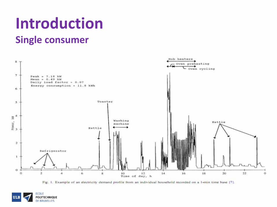
Introduction Single consumer
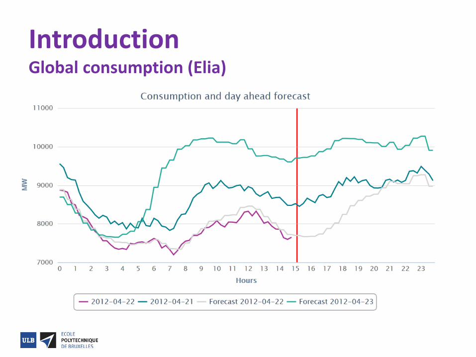
Introduction Global consumption (Elia)
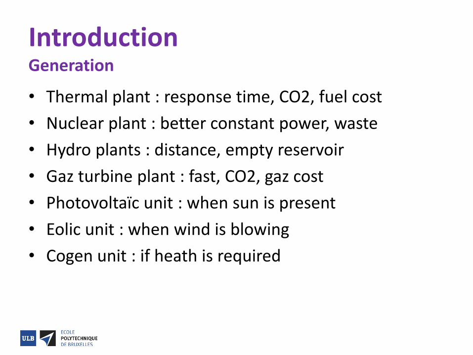
Introduction Generation • Thermal plant : response time, CO2, fuel cost
• Nuclear plant : better constant power, waste
• Hydro plants : distance, empty reservoir
• Gaz turbine plant : fast, CO2, gaz cost
• Photovoltaïc unit : when sun is present
• Eolic unit : when wind is blowing
• Cogen unit : if heath is required
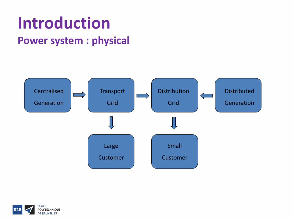
Introduction Power system : physical
Centralised
Generation
Transport
Grid
Distribution
Grid
Distributed
Generation
Large
Customer
Small
Customer
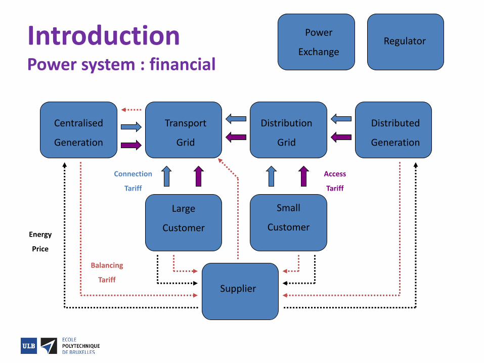
Introduction Power system : financial
Centralised
Generation
Transport
Grid
Distribution
Grid
Distributed
Generation
Large
Customer
Small
Customer
Supplier
Energy
Price
Balancing
Tariff
Connection
Tariff
Access
Tariff
Power
Exchange Regulator
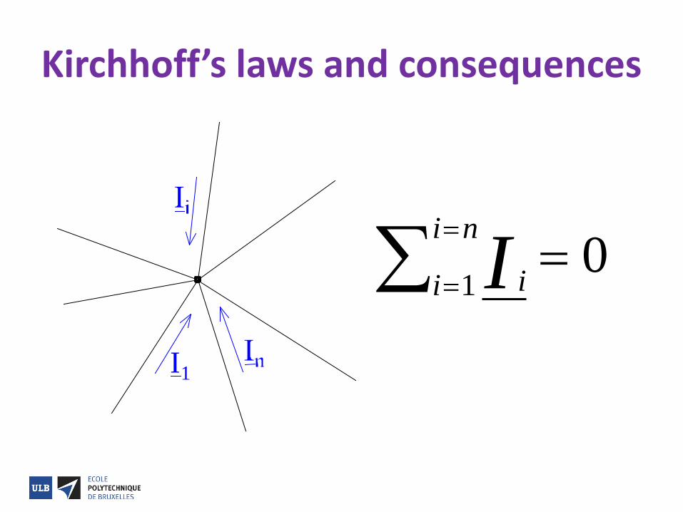
Kirchhoff’s laws and consequences
I1
ii
i n
I
1
0

Kirchhoff’s laws and consequences
ii
i n
V
1
0
( )ii
i n
i iE Z I
10
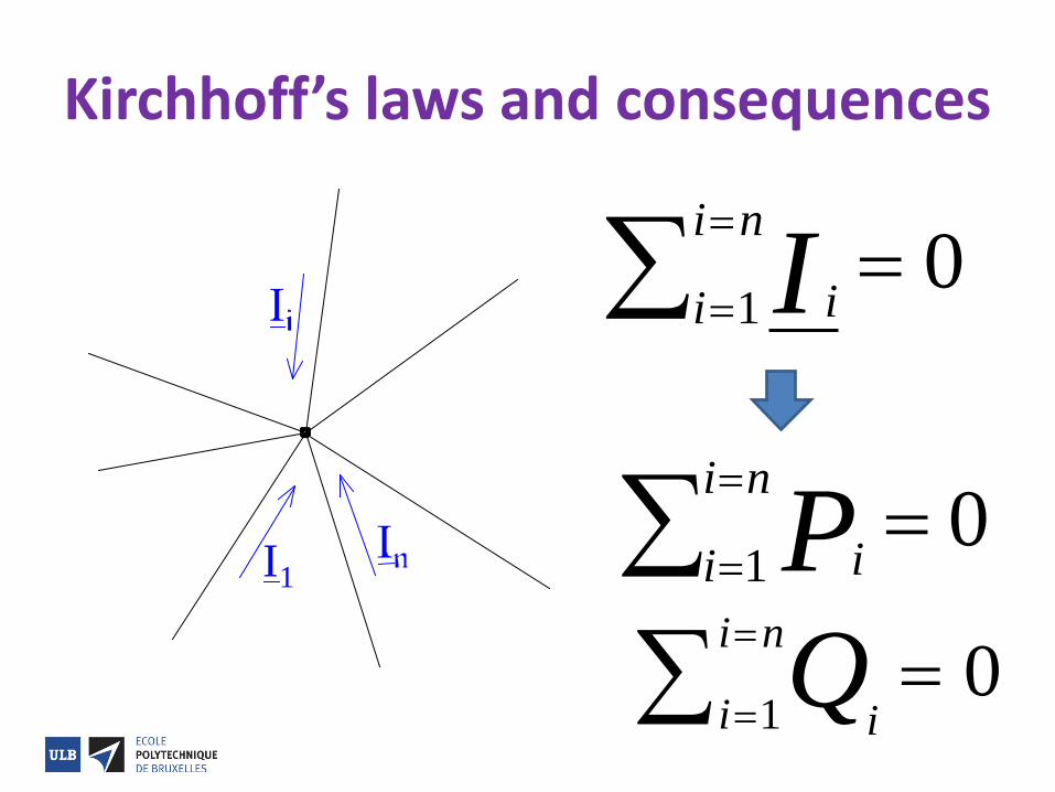
Kirchhoff’s laws and consequences
I1
ii
i n
I
1
0
ii
i n
Q
1
0
ii
i n
P
1
0
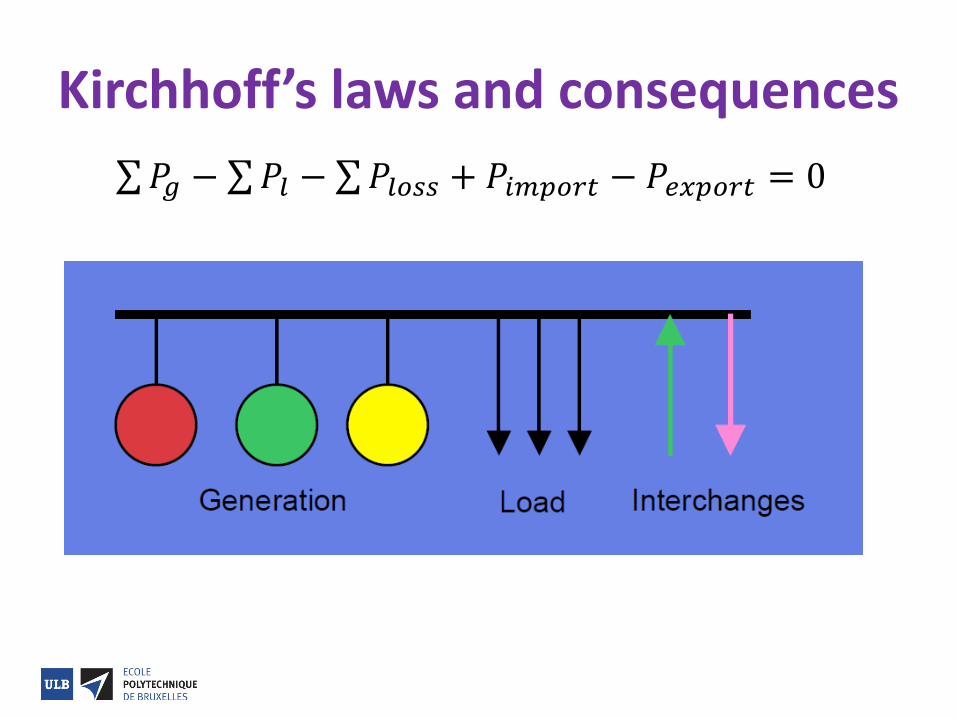
Kirchhoff’s laws and consequences
𝑃𝑔 − 𝑃𝑙 − 𝑃𝑙𝑜𝑠𝑠 + 𝑃𝑖𝑚𝑝𝑜𝑟𝑡 − 𝑃𝑒𝑥𝑝𝑜𝑟𝑡 = 0
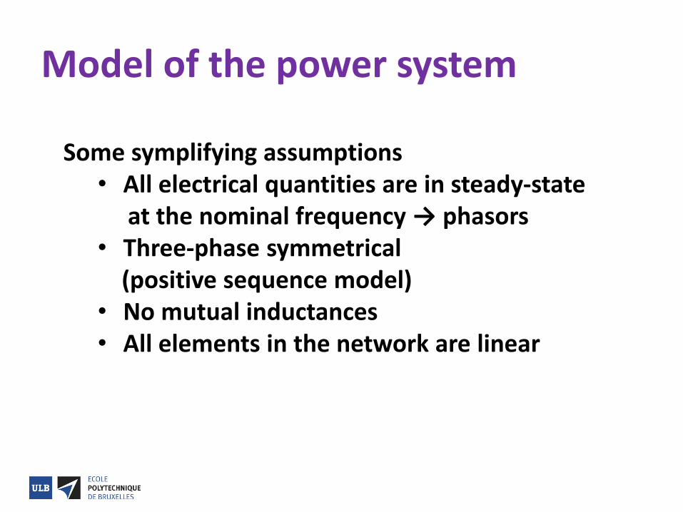
Model of the power system
Some symplifying assumptions
• All electrical quantities are in steady-state at the nominal frequency → phasors • Three-phase symmetrical (positive sequence model) • No mutual inductances • All elements in the network are linear
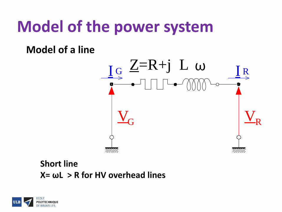
Model of the power system
Model of a line Short line X= ωL > R for HV overhead lines
V VG R
I G I RZ=R+j L ω
Model of the power system
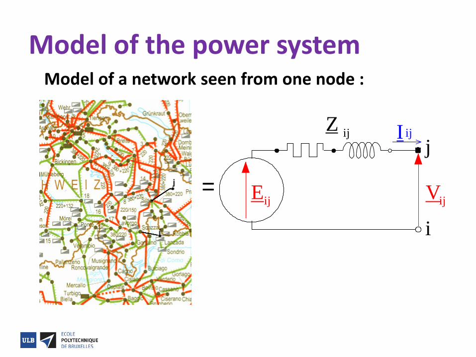
Model of a network seen from one node :
= E Vij
IZ
i
jij ij
ij
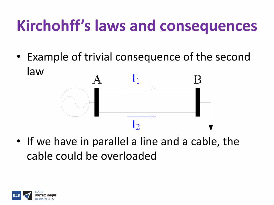
Kirchohff’s laws and consequences
• Example of trivial consequence of the second law
• If we have in parallel a line and a cable, the cable could be overloaded
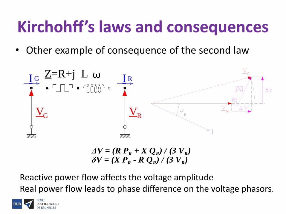
Kirchohff’s laws and consequences • Other example of consequence of the second law
V VG R
I G I RZ=R+j L ω
ΔV = (R PR + X QR) / (3 VR) δV = (X PR - R QR) / (3 VR)
Reactive power flow affects the voltage amplitude Real power flow leads to phase difference on the voltage phasors.
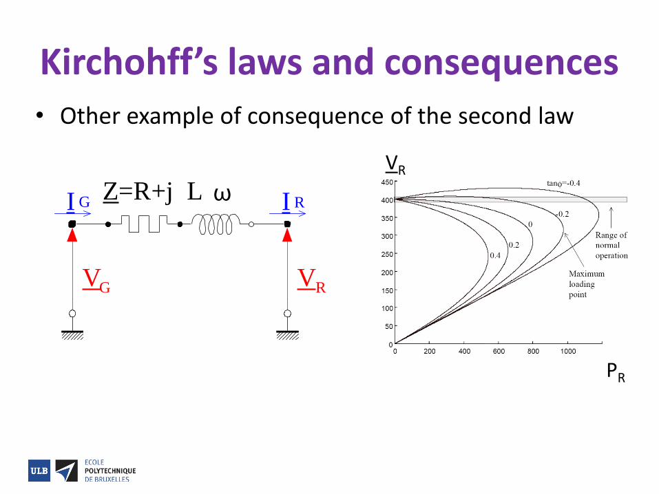
Kirchohff’s laws and consequences • Other example of consequence of the second law
V VG R
I G I RZ=R+j L ω
V VR
PR
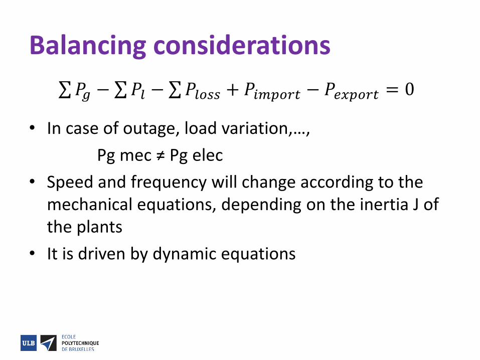
Balancing considerations
• In case of outage, load variation,…,
Pg mec ≠ Pg elec
• Speed and frequency will change according to the mechanical equations, depending on the inertia J of the plants
• It is driven by dynamic equations
𝑃𝑔 − 𝑃𝑙 − 𝑃𝑙𝑜𝑠𝑠 + 𝑃𝑖𝑚𝑝𝑜𝑟𝑡 − 𝑃𝑒𝑥𝑝𝑜𝑟𝑡 = 0
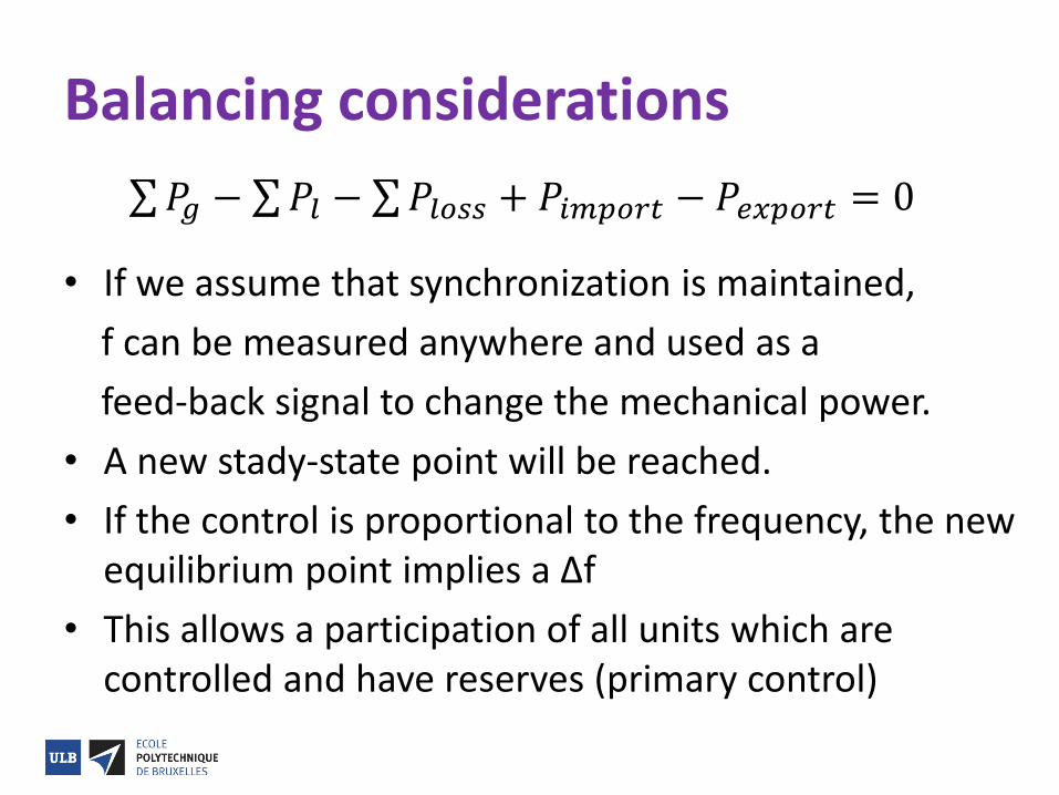
Balancing considerations
• If we assume that synchronization is maintained,
f can be measured anywhere and used as a
feed-back signal to change the mechanical power.
• A new stady-state point will be reached.
• If the control is proportional to the frequency, the new equilibrium point implies a Δf
• This allows a participation of all units which are controlled and have reserves (primary control)
𝑃𝑔 − 𝑃𝑙 − 𝑃𝑙𝑜𝑠𝑠 + 𝑃𝑖𝑚𝑝𝑜𝑟𝑡 − 𝑃𝑒𝑥𝑝𝑜𝑟𝑡 = 0
Balancing considerations
• If we add an integral feedback based on an error signal which mixes Δf + K ΔPzone, we can go back to fnom and to the planned balance on P import/export (secondary control)
• It is a short term process (seconds to minutes)
• It assumes that we reach a new equilibrium point.
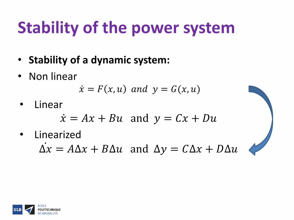
Stability of the power system
• Stability of a dynamic system:
• Non linear 𝑥 = 𝐹 𝑥, 𝑢 𝑎𝑛𝑑 𝑦 = 𝐺(𝑥, 𝑢)
• Linear 𝑥 = 𝐴𝑥 + 𝐵𝑢 and 𝑦 = 𝐶𝑥 + 𝐷𝑢
• Linearized
∆𝑥 = 𝐴∆𝑥 + 𝐵∆𝑢 and ∆𝑦 = 𝐶∆𝑥 + 𝐷∆𝑢
Stability of the power system
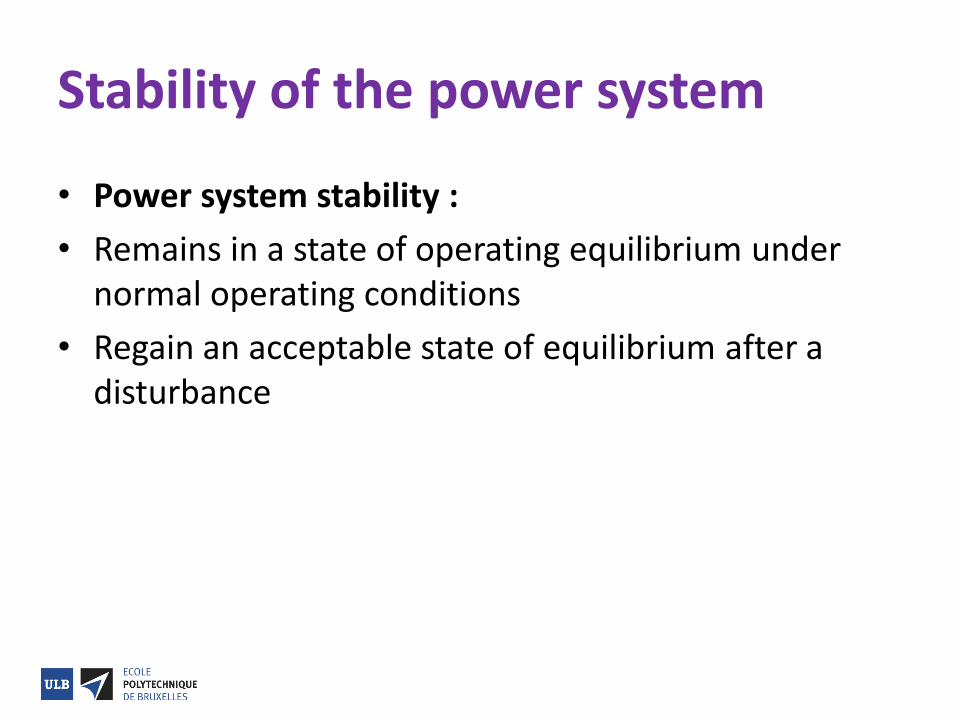
• Power system stability :
• Remains in a state of operating equilibrium under normal operating conditions
• Regain an acceptable state of equilibrium after a disturbance
Stability of the power system
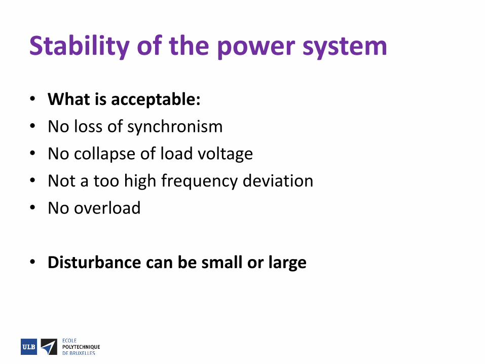
• What is acceptable:
• No loss of synchronism
• No collapse of load voltage
• Not a too high frequency deviation
• No overload
• Disturbance can be small or large
Static Stability of the power system
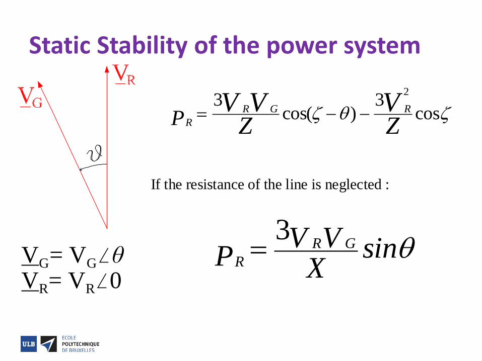
VG= VGθVR= VR0
R
R G R
PV V V
Z Z
3 32
cos( ) cos
If the resistance of the line is neglected :
R
R G
PV V
Xsin
3
Static Stability of the power system
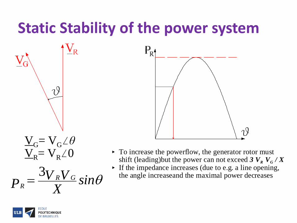
VG= VGθVR= VR0
R
R G
PV V
Xsin
3
To increase the powerflow, the generator rotor mustshift (leading)but the power can not exceed 3 VR VG / X
If the impedance increases (due to e.g. a line opening,the angle increaseand the maximal power decreases
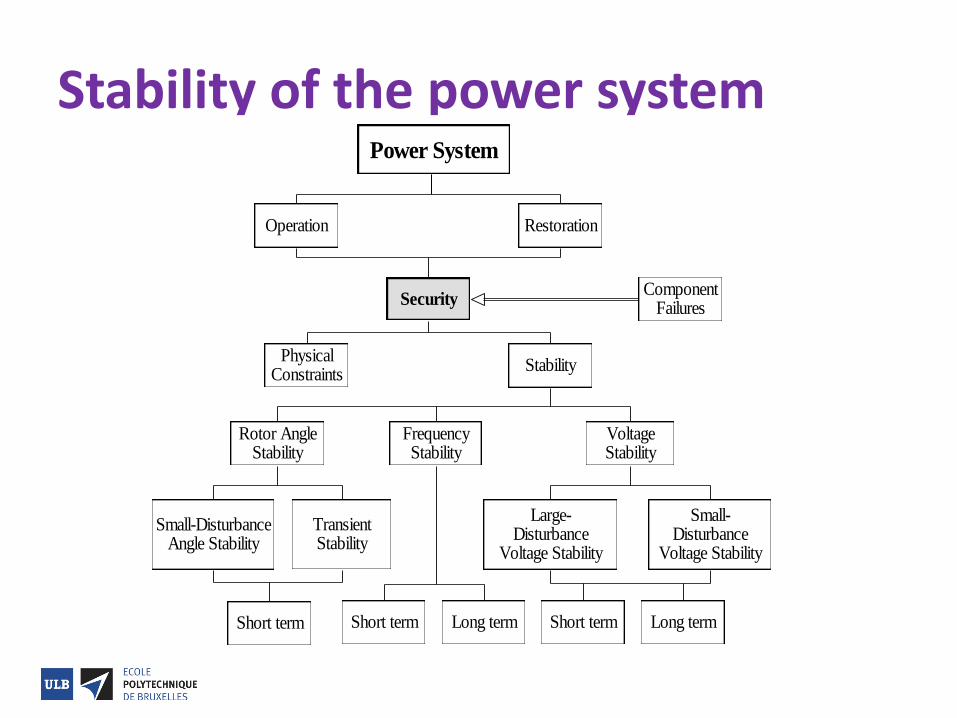
Stability of the power system
Operation Restoration
Power System
ComponentFailures
Security
PhysicalConstraints
FrequencyStability
VoltageStability
Stability
Small-DisturbanceAngle Stability
TransientStability
Rotor AngleStability
Short term
Large-Disturbance
Voltage Stability
Small-Disturbance
Voltage Stability
Short term Long termShort term Long term
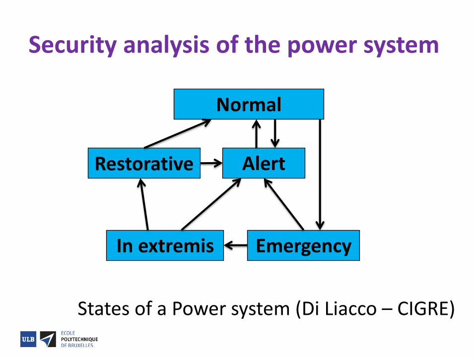
Security analysis of the power system
Normal
Alert Restorative
Emergency In extremis
States of a Power system (Di Liacco – CIGRE)
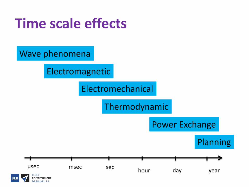
Time scale effects
Wave phenomena
Electromagnetic
Electromechanical
Thermodynamic
Power Exchange
Planning
µsec msec sec hour day year
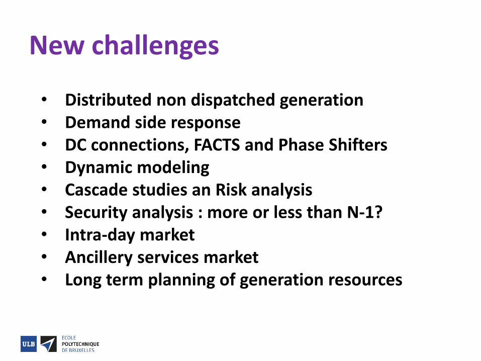
New challenges
• Distributed non dispatched generation • Demand side response • DC connections, FACTS and Phase Shifters • Dynamic modeling • Cascade studies an Risk analysis • Security analysis : more or less than N-1? • Intra-day market • Ancillery services market • Long term planning of generation resources
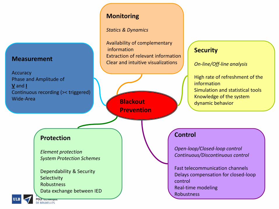
Blackout Prevention
Measurement Accuracy Phase and Amplitude of V and I Continuous recording (>< triggered) Wide-Area
Monitoring Statics & Dynamics Availability of complementary information Extraction of relevant information Clear and intuitive visualizations
Security On-line/Off-line analysis High rate of refreshment of the information Simulation and statistical tools Knowledge of the system dynamic behavior
Protection Element protection System Protection Schemes Dependability & Security Selectivity Robustness Data exchange between IED
Control Open-loop/Closed-loop control Continuous/Discontinuous control Fast telecommunication channels Delays compensation for closed-loop control Real-time modeling Robustness
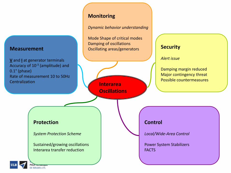
Interarea Oscillations
Measurement V and I at generator terminals Accuracy of 10-3 (amplitude) and 0.1° (phase) Rate of measurement 10 to 50Hz Centralization
Monitoring Dynamic behavior understanding Mode Shape of critical modes Damping of oscillations Oscillating areas/generators Security
Alert issue Damping margin reduced Major contingency threat Possible countermeasures
Protection System Protection Scheme Sustained/growing oscillations Interarea transfer reduction
Control Local/Wide-Area Control Power System Stabilizers FACTS
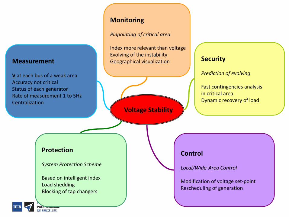
Voltage Stability
Measurement V at each bus of a weak area Accuracy not critical Status of each generator Rate of measurement 1 to 5Hz Centralization
Monitoring Pinpointing of critical area Index more relevant than voltage Evolving of the instability Geographical visualization Security
Prediction of evolving Fast contingencies analysis in critical area Dynamic recovery of load
Protection System Protection Scheme Based on intelligent index Load shedding Blocking of tap changers
Control Local/Wide-Area Control Modification of voltage set-point Rescheduling of generation
References • Kundur – Power System Stability • Gomes-Exposito, Conejo, Canizares – Eletric Energy
Systems – Analysis and Operation • Machowski, Bialek, Bumby - Power System Dynamics
– Stability and Control • Kirschen – Fundamentals of Power System Economics • Elia Website
Acknowledgments • Prof. Poncelet, Warichet, Genêt, Klopfert