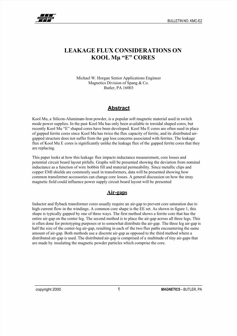
BULLETIN NO. KMC-E2 copyright 2000 1MAGNETICS– BUTLER, PALEAKAGE FLUX CONSIDERATIONS ON KOOL Mµ “E” CORES Michael W. Horgan Senior Applications Engineer Magnetics Division of Spang & Co. Butler, PA 16003 Abstract Kool Mu, a Silicon-Aluminum-Iron powder, is a popular soft magnetic material used in switch mode power supplies. In the past Kool Mu has only been available in toroidal shaped cores, but recently Kool Mu “E” shaped cores have been developed. Kool Mu E cores are often used in place of gapped ferrite cores since Kool Mu has twice the flux capacity of ferrite, and its distributed air- gapped structure does not suffer from the gap loss concerns associated with ferrites. The leakage flux of Kool Mu E cores is significantly unlike the leakage flux of the gapped ferrite cores that they are replacing. This paper looks at how this leakage flux impacts inductance measurement, core losses and potential circuit board la yout pitfalls. Graphs will be presented showi ng the deviation from no minal inductance as a function of wire bobbin fill and material permeability. Since metallic clips and copper EMI shields are commonly used in transformers, data will be presented showing how common transformer accessories can change core losses. A general discussion on how the stray magnetic field could influence power supply circuit board layout will be presented Air-gaps Inductor and flyback transformer cores usually require an air-gap to prevent core saturation due to high current flow in the windings. A common core shape is the EE set. As shown in figure 1, this shape is typically gapped by one of three ways. The first method shows a ferrite core that has the entire air-gap on the center leg. The second method is to place the air-gap across all three legs. This is often done for prototyping purposes or to somewhat distribute the air-gap. The three leg air-gap is half the size of the center-leg air-gap, resulting in each of the two flux paths encountering the same amount of air-gap. Both methods use a discrete air-gap as opposed to the third method where a distributed air-gap is used. The distributed air-gap is comprised of a multitude of tiny air-gaps that are made by insulating the magnetic powder particles which comprise the core.