Embed Size (px)
Citation preview
Inst
alla
tion
En
glis
h
Inst
alla
tion
Fra
nça
is
Inst
alac
ión
Esp
añol
Inst
alaç
ão P
ortu
guês
Lutron Electronics Co., Inc. | 7200 Suter Road, Coopersburg, PA 18036-1299, U.S.A.
Warranty For warranty information, please see the Warranty enclosed with the product, or visit http://www.lutron.com/TechnicalDocumentLibrary/HomeWorks_Intl_Warranty.pdf
Lutron, EcoSystem, and are registered trademarks of Lutron Electronics Co., Inc. NEC is a registered trademark of the National Fire Protection Association, Quincy, Massachusetts.
DALI is a registered trademark of ZVEI - Zentralverband Elektrotechnik- und Elektronikindustrie e. V.
©2012 Lutron Electronics Inc.
7
2
4
5
6
À lire avant de procéder à l’installation.Risque de choc. Peut entraîner de graves blessures ou la mort. Couper l’alimentation au niveau du disjoncteur avant d’installer l’appareil. Il peut être nécessaire d’utiliser plusieurs sectionneurs pour couper l’alimentation de cet équipement.
AVERTISSEMENT
1
Utilisation des LED pour le dépannage
LED Comportement de la LED DescriptionPower (Alimentation)
Allumée fixe Fonctionnement normal
Éteinte Panne générale du système/absence d’alimentation
Hi Temp (Température élevée)
Éteinte Fonctionnement normal
1 clignotement toutes les 8 secondes
L’appareil est trop chaud, les charges sont limitées à 25 % de la puissance
Allumée fixe L’appareil est trop chaud, les charges sont éteintes
Clignotement L’appareil est revenu à une température acceptable
LED de zone 1-4
Éteinte Fonctionnement normal - zone éteinte
Clignotement Zone sélectionnée
Allumée fixe Fonctionnement normal - zone allumée
QS Allumée/clignotement Dispositif émettant/recevant sur le bus QS
3 clignotements rapides toutes les 4 secondes
Erreur de communication
Éteinte Le dispositif n’émet/ ne reçoit pas de signal sur le bus QS
CCI Allumée fixe Fonctionnement normal
Clignotement rapide Mode d’urgence/contact ouvert/cavalier absent
H Allumée fixe Zone sélectionnée-Supérieure à 66 %
M Allumée fixe Zone sélectionnée-Supérieure à 33 %
L Allumée fixe Zone sélectionnée-Supérieure à 1 %
Éteinte Zone sélectionnée-Éteinte
Input (Entrée)Program (Programme) Def Opt1Opt2Opt3 Sans objet
Inutilisé sur les numéros de référence LQSE-4T10-D et LQSE-4S10-D.
8 Vérifier les luminaires - Fonctionnement en mode manuel
Boutons de zone - Sélection d’une zone à commander.
Bouton augmenter/diminuer - Allumer et éteindre les charges. - Faire varier le niveau des charges (LQSE-4T10-D uniquement)
Remarque : les boutons Program, Input et Option ne sont pas utilisés sur les modèles LQSE.
3
Les boutons et les LED de l’appareil sont utilisés pour la programmation et le diagnostic. Si le câblage est accessible lors de l’accès aux boutons et aux LED, l’accès à l’appareil doit être effectué par un électricien qualifié, conformément aux normes locales.
Remarque : pour davantage d’informations sur le fonctionnement et les valeurs nominales de l’appareil, veuillez consulter la réf. Lutron 369610 sur www.lutron.com
Montage•MonterdansunearmoireIP20(minimum)avecrailDINintégré.• Lesrelaisinternesémettentundéclicaudible,aussiilfautlesmonterdansunlieuoùcebruit
est acceptable.•Lalargeurdel’appareilestde9modulesDIN(161,7 mm).•MontersurrailDINàl’aidedes4loquetsaubasdel’appareil.Lesattachespeuventêtresorties
à l’aide d’un tournevis.
Câblage du secteur•Couperl’alimentationetcâblerlesecteuràl’appareilcommeindiqué.•Mettresoustension.LaLEDd’alimentations’allumesil’appareilestcorrectementbranché.
Câblage de zone (230 V~)•Couperl’alimentation.•Avant de câbler les charges sur l’unité, raccorder chaque zone à la ligne à l’aide d’un connecteur provisoireetappliquerlatensionpourvérifierlecâblagedelacharge.
•Couperànouveaul’alimentation.•Raccorderleschargesàl’appareilcommeillustré.•Mettresoustension.Lesboutonsdezoneetmonter/descendrepeuventêtreutiliséspourcommander
localement la chaque zone.
Bus QS (IEC PELV / NECR Class 2)•Couperl’alimentationpendantlaréparationdel’appareil.•RaccorderlebusQSàl’appareilcommeillustré.Notezquelesbornes3et4sontunepairetorsadée,
blindée.•Lebuspeutêtreensérieouenétoileetlalongueurnedoitpasdépasser600 m. Remarque : Ne pas raccorder la borne n° 2.
Entrées d’urgence à contacts secs (IEC PELV / NECR Class 2)•Siellen’estpasnécessaire,laisserlecavalierpré-installésurlesbornesàcontactssecs.•Mettrehorstensiondurantlarévisiondel’appareiletcâblerlescontactssecscommeindiqué.• L’entréeestàcontactnormalementfermée.Sielleouverte,l’appareilpasseauxniveauxd’éclairage
de secours et ne répond pas aux entrées des autres appareils.
Câblage 0-10 V (LQSE-4T10-D uniquement)•Leszones0-10 V1à4possèdentunedoubleisolationparrapportauxautresentréesetsorties.• Leszones0-10 V1à4nesontpasisoléeslesunesdesautres.Ellespartagentlemêmecommun
(les bornes négatives « – » sont connectées entre elles).•RaccorderuniquementlescircuitsSELV/PELVouraccorderuniquementlescircuitsnonSELV/PELV
aux zones 0-10 V 1 à 4. Ne pas mélanger les circuits SELV/PELV et les circuits non SELV/PELV.•Respectertouteslesnormeslocalesetnationalespourconnaîtrelesexigencesdeséparation.
GarantiePour plus d’informations sur la garantie, voir la garantie jointe au produit ou visiter http://www.lutron.com/TechnicalDocumentLibrary/HomeWorks_Intl_Warranty.pdf
Lutron, EcoSystem et sont des marques déposées de Lutron Electronics Co., Inc. NEC est une marque déposée et une marque de service de la National Fire Protection Association, Quincy, Massachusetts.
DALI est une marque déposée de ZVEI - Zentralverband Elektrotechnik- und Elektronikindustrie e. V.
©2012 Lutron Electronics Inc.
7
2
4
5
6
Leer antes de la instalación.Peligro de descargas eléctricas. Pueden causar lesiones graves o mortales. Corte el suministro eléctrico en el magnetotérmico antes de instalar la unidad. Puede ser necesaria más de una desconexión para cortar la alimentación eléctrica al equipo.
PRECAUCIÓN
1
Utilización de LEDs para la solución de problemas
LED Respuesta de los LED DescripciónPower (Alimentación)
Encendido permanente Funcionamiento normal
Apagado Fallo general del sistema/sin alimentación
Hi Temp (Temperatura Alta)
Apagado Funcionamiento normal
1 parpadeo cada 8 segundos La unidad está demasiado caliente, cargas escalonadas hasta el 25% potencia
Encendido permanente La unidad está demasiado caliente, cargas apagadas
Parpadeando La unidad se ha enfriado hasta una temperatura aceptable
LEDs de zona 1-4
Apagado Funcionamiento normal – zona apagada
Parpadeando Zona seleccionada
Encendido permanente Funcionamiento normal – zona encendida
QS Encendido/parpadeo Dispositivo transmitiendo/recibiendo en el bus QS
3 parpadeos rápidos cada 4 segundos
Error de comunicación
Apagado El dispositivo no transmite/recibe en el bus QS
CCI Encendido permanente Funcionamiento normal
Parpadeo rápido Modo de emergencia/Contacto abierto/ Falta puente
H Encendido permanente Zona seleccionada-Superior al 66%
M Encendido permanente Zona seleccionada-Superior al 33%
L Encendido permanente Zona seleccionada-Superior al 1%
Apagado Zona seleccionada-apagado
Input (Entrada)Program (Programa) Def Opt 1Opt 2Opt 3 N.A.
No usado en los números de modelo LQSE-4T10-D y LQSE-4S10-D.
8 Verificar luces - Funcionamiento de modo manual
Botones de zona - Selecciona la zona a controlar.
Botones subir/bajar - Enciende y apaga las cargas. - Regula las cargas arriba y abajo (LQSE-4T10-D solamente).
Nota: Los botones Programa, Entrada y Opción no se usan en los modelos LQSE.
3
Los botones y LEDs del frente de la unidad se utilizan para la programación y solución de averías. Si el cableado está expuesto cuando se accede a los botones y LEDs, el acceso lo realizará un electricista cualificado, siguiendo los códigos locales.
Nota: Para información adicional sobre el funcionamiento y las capacidades, consulte Lutron P/N 369610 en www.lutron.com
Montaje•RealiceelmontajeenuncuadroIP20(mínimo)conraílDINintegrado.• Losrelésinternosproducenruidos;realiceelmontajedondenocausenmolestias.• Launidadtiene9módulosDINconunaanchurade161,7mm.•RealiceelmontajeenelraílDINutilizandolos4clipsdelaparteinferiordelaunidad.
Los clips pueden soltarse con un destornillador.
Cableado de red•Apaguelacorrienteyconectelaunidadalaredcomosemuestra.•ApliquecorrienteyelLEDdealimentaciónseiluminarásilaunidadsehaconectadocorrectamente.
Cableado de zona (230 V~)•Apagar.•Antes de conectar las cargas a la unidad,conecteunazonaalíneausandounconectordecable
temporal y alimente corriente para verificar el cableado de carga.•Apagardenuevo.•Conectelascargasalaunidadcomosemuestra.•Apliquecorrientealazona,ysepuedenusarlosbotonessubir/bajarparacontrolarlocalmente
cada zona.
Enlace QS (IEC PELV / NECR Class 2)•Apaguelacorrientedurantelostrabajosdeserviciodelaunidad.•ConecteelenlaceQSalaunidadcomosemuestra,observequelosterminales3y4son
un par trenzado y apantallado.•ElenlacesepuedeconectarencadenaoenderivaciónenT,conunalongitudnosuperiora600m. Nota: No conecte al terminal nº 2.
Entrada de cierre de contacto de emergencia (IEC PELV / NECR Class 2)•Sinoesnecesario,dejeelpuentepreinstaladoenlosterminalesCCI.•DesconectelacorrientedurantelostrabajosdeservicioyconecteelCCIcomosemuestra.• Laentradaestánormalmentecerrada.Siestáabierta,launidadsepondráenniveles
de iluminación de emergencia y no responderá a las entradas de otros dispositivos.
Cableado de 0-10 V (LQSE-4T10-D solamente)•Laszonas1-4de0-10Vestándoblementeaisladasdelasrestantesentradasysalidas.• Laszonas1-4de0-10Vnoseaíslanentreellas.Compartenlosmismosterminalescomunes
(los terminales negativos “–” se conectan internamente entre ellos).•ConectesólocircuitosSELV/PELV,oconectesólocircuitosnoSELV/PELValaszonas1-4de0-10 V.
No mezcle circuitos SELV/PELV y circuitos que no sean SELV/PELV.•Sigatodosloscódigoseléctricosnacionalesylocalesparalosrequisitosdeseparación.
GarantíaPara obtener información sobre la garantía, consulte la garantía que se adjunta con el producto o visite http://www.lutron.com/TechnicalDocumentLibrary/HomeWorks_Intl_Warranty.pdf
Lutron, EcoSystem y son marcas registradas de Lutron Electronics Co., Inc. NEC es una marca registrada de National Fire Protection Association, Quincy, Massachusetts.
DALI es una marca registrada de ZVEI - Zentralverband Elektrotechnik- und Elektronikindustrie e. V.
©2012 Lutron Electronics Inc.
7
2
4
5
6
Ler atentamente antes de instalar.Perigo de choque eléctrico. Pode provocar lesões graves ou morte. Desligar a corrente no disjuntor antes de instalar a unidade. Pode ser necessário mais de um desligamento para descarregar toda a corrente do equipamento.
AVISO
1
Usar LEDs para resolução de problemas
LED Comportamento do LED DescriçãoPower (Alimentação)
Continuamente aceso Funcionamento normal
Apagado Falha geral do sistema/Sem alimentação
Hi Temp (Alta temp.)
Apagado Funcionamento normal
Pisca 1 vez de 8 em 8 segundos A unidade está excessivamente quente, as cargas ascenderam a 25% de potência
Continuamente aceso A unidade está excessivamente quente, as cargas desligaram
A piscar A unidade arrefeceu até uma temperatura aceitável
LEDs de zona 1-4
Apagado Funcionamento normal - zona desligada
A piscar Zona seleccionada
Continuamente aceso Funcionamento normal - zona ligada
QS Aceso/a piscar Dispositivo a transmitir/receber na ligação QS
Pisca rapidamente 3 vezes de 4 em 4 segundos
Erro de comunicação
Apagado O dispositivo não está a transmitir/receber na ligação QS
CCI Continuamente aceso Funcionamento normal
A piscar rapidamente Modo de emergência/contacto aberto/ ponte em falta
H Continuamente aceso Zona seleccionada – superior a 66%
M Continuamente aceso Zona seleccionada – superior a 33%
L Continuamente aceso Zona seleccionada – superior a 1%
Apagado Zona seleccionada – deslig.
Input (Entrada)Program (Programa) Def Opt 1Opt 2Opt 3 n/a
Não usado nos modelos LQSE-4T10-D e LQSE-4S10-D.
8 Luzes de verificação – Funcionamento em modo manual
Botões de zona - Selecciona a zona a controlar.
Botões de aumentar/diminuir - Liga e desliga as cargas. - Aumenta e diminui o consumo das cargas. (apenas LQSE-4T10-D)
Nota: Os modelos LQSE não usam os botões “Program”, “Input” e “Option”.
3
Os botões e LED existentes na unidade são utilizados para operações de programação e resolução de problemas. Se a instalação estiver exposta quando aceder aos botões e LED, o acesso à unidade deverá ser feito apenas por um electricista certificado, de acordo com as normas locais.
Nota:Paramaisinformaçõessobreofuncionamentoecaracterísticasdaunidade,consulte Lutron ref. 369610 em www.lutron.com
Montagem•MontarempainelIP20(mínimo)comcalhaDINintegrada.•Osrelésprovocamumruídoperceptível;montaremlocalondeoruídosejaaceitável.•Aunidadepossui9módulosDINcom161,7mmdelargura.•MontaremcalhaDINutilizando4gramposnaparteinferiordaunidade.Épossívelretiraros
grampos com uma chave de fendas.
Ligação da rede de alimentação•Desligaracorrenteeaalimentaçãodaredeparaaunidadeconformeilustrado.• Ligaraalimentação;oLEDindicadordeenergiaacendeseainstalaçãoestivercorrecta.
Ligação das zonas (230 V~)•Desligaraalimentação.•Antes de ligar cargas à unidade, ligar cada zona à linha com um conector provisório e
aplicar corrente para verificar a ligação da carga.•Desligarnovamenteaalimentação.• Ligarascargasàunidadecomoilustrado.• Ligaraalimentaçãodazona;osbotõesdeaumentar/diminuirpodemserutilizadospara
controlar localmente cada zona.
Ligação QS (IEC PELV / NECR Class 2)•Desligaraalimentaçãoduranteostrabalhosdemanutençãonaunidade.• LigaraligaçãoQSàunidadeconformeilustrado;nota:osterminais3e4possuemcabo
blindado de par torcido.•Aligaçãopodeserdotipo“daisychain”ouderivaçãoemT,comcomprimentonuncasuperior
a 600 m. Nota: Não ligar ao terminal 2.
Entrada para fecho de contacto de emergência (IEC PELV / NECR Class 2)•Senãofornecessário,deixarapontepré-instaladanosterminaisCCI.•Desligaraalimentaçãodurantearealizaçãodetrabalhosdemanutençãonaunidade
e ligar CCI conforme ilustrado.•Aentradaestánormalmentefechada;seestiveraberta,passaráparaníveisdeiluminação
de emergência e não responderá a entradas de outros dispositivos.
Ligação de 0-10 V (apenas LQSE-4T10-D)•Aszonas1-4de0-10Vpossuemisolamentoduploemrelaçãoatodasasoutrasentradas esaídas.
•Aszonas1-4de0-10Vnãosãoisoladasentresi.Partilhamomesmocomum(osterminaisnegativos “-” estão internamente ligados entre si).
•LigarapenasoscircuitosSELV/PELV,ouligarapenasoscircuitosnão-SELV/PELVàszonas 1-4 de 0-10 V. Não misturar circuitos SELV/PELV com circuitos não SELV/PELV.
•Cumprirtodasasnormasnacionaiselocaisrelativasarequisitosdeseparação.
GarantiaPara informações sobre a garantia, consultar a Garantia incluída no produto ou visitar o site http://www.lutron.com/TechnicalDocumentLibrary/HomeWorks_Intl_Warranty.pdf
Lutron, EcoSystem, e são marcas registadas da Lutron Electronics Co., Inc. NEC é uma marca registada da National Fire Protection Association, Quincy, Massachusetts.
DALI é uma marca registada da ZVEI - Zentralverband Elektrotechnik- und Elektronikindustrie e. V.
©2012 Lutron Electronics Inc.
2
4
5
6
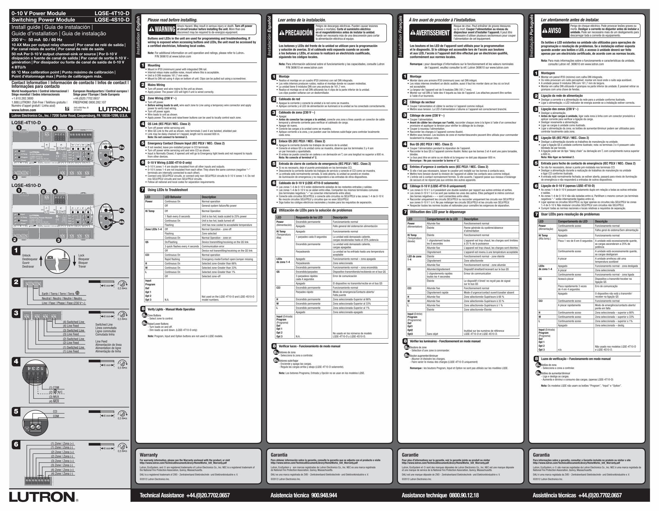
Please read before installing.Shock Hazard. May result in serious injury or death. Turn off power at circuit breaker before installing the unit. More than one disconnect may be required to de-energize equipment.WARNING
1
7 Using LEDs to Troubleshoot
LED LED Behavior DescriptionPower Continuous On Normal operation
Off General system failure/No power
Hi Temp Off Normal Operation
1 flash every 8 seconds Unit is too hot, loads scaled to 25% power
Continuous On Unit is too hot, loads turned off
Flashing Unit has now cooled to acceptable temperature
Zone LEDs 1-4 Off Normal Operation - zone off
Flashing Zone selected
Continuous On Normal Operation - zone on
QS On/Flashing Device transmitting/receiving on the QS link
3 quick flashes every 4 seconds Communication error
Off Device not transmitting/receiving on the QS link
CCI Continuous On Normal operation
Rapid flashing Emergency mode/Contact open/Jumper missing
H Continuous On Selected zone-Greater than 66%
M Continuous On Selected zone-Greater than 33%
L Continuous On Selected zone-Greater than 1%
Off Selected zone-off
Input ProgramDefOpt 1Opt 2Opt 3 N.A.
Not used on the LQSE-4T10-D and LQSE-4S10-D model numbers.
Verify Lights - Manual Mode Operation
Zone Buttons - Select zone to control.
Raise/Lower Buttons - Turn loads on and off. - Dim loads up and down. (LQSE-4T10-D only)
Note: Program, Input and Option buttons are not used in LQSE models.
3
Buttons and LEDs in the unit are used for programming and troubleshooting. If wiring is exposed when accessing buttons and LEDs, the unit must be accessed by a certified electrician, following local codes.
Note: For additional information on unit operation and ratings, please refer to LutronR P/N 369610 at www.lutron.com
Mounting•MountinIP20(minimum)panelwithintegratedDINrail.• Internalrelaysmakeaudiblenoise,mountwherethisisacceptable.•Unitis9DINmodules161,7mmwide.•MounttoDINrailusing4clipsonbottomofunit.Clipscanbepulledoutusingascrewdriver.
Mains Wiring•Turnoffpowerandwiremainstotheunitasshown.•Applypower.ThepowerLEDwilllightifunitiswiredcorrectly.
Zone Wiring (230 V~)•Turnoffpower.•Before wiring loads to unit, wire each zone to Line using a temporary wire connector and apply
power to verify load wiring.•Turnoffpoweragain.•Wireloadstounitasshown.•Applypower.Thezoneandraise/lowerbuttonscanbeusedtolocallycontroleachzone.
QS Link (IEC PELV / NECR Class 2)•Turnoffpowerwhileservicingunit.•WireQSLinktotheunitasshown,noteterminals3and4aretwisted,shieldedpair.• Linkmaybedaisychainedort-tapped,lengthnottoexceed600m. Note: Do not connect to terminal 2.
Emergency Contact Closure Input (IEC PELV / NECR Class 2)• Ifnotneeded,leavepre-installedjumperinCCIterminals.•TurnoffpowerwhileservicingunitandwireCCIasshown.• InputisNormallyClosed,ifopenedunitwillgotoEmergencylightlevelsandnotrespondtoinputs
from other devices.
0-10 V Wiring (LQSE-4T10-D only)•0-10Vzones1-4aredouble-insulatedfromallotherinputsandoutputs.•0-10Vzones1-4arenotinsulatedfromeachother.Theysharethesamecommon(negative“–”
terminals are internally connected to each other).•ConnectonlySELV/PELVcircuits,orconnectonlynon-SELV/PELVcircuitsto0-10 Vzones1-4.Donot
mix SELV/PELV circuits and non-SELV/PELV circuits.•Followallnationalandlocalcodesforseparationrequirements.
88a
8a
8a
8a
8b
8b
8b
8b
5
220 - 240 V~
Neutral | Neutro | Neutre | NeutroLine | Fase | Phase | Fase (230 V~)
Earth | Tierra | Terre | Terra
6
MU
X
CO
M
MU
X
QS
Def
Opt1
Opt2
0-10 V Power ModuleLQSE-4T10-D230 V~ 50/60 Hz 50 mAwww.lutron.com +44.(0)20.7680.4481
1 2 3 4Outputs 230 V~ 10 AX each
Zone 1 Zone 2 Zone 3 Zone 4
Option
L N
µ
Z096
Opt3
CC
I
CCI
CO
M
0,5 N•mAll Others
8 mm1,2 N•mMains Only
Input
Hi Temp
Program
Power
H
M
L
Zones0-10 V-
50 mA
Up
3
2
MU
X
CO
M
MU
X
QS
Def
Opt1
Opt2
0-10 V Power ModuleLQSE-4T10-D230 V~ 50/60 Hz 50 mAwww.lutron.com +44.(0)20.7680.4481
1 2 3 4Outputs 230 V~ 10 AX each
Zone 1 Zone 2 Zone 3 Zone 4
Option
L N
µ
Z096
Opt3
CC
I
CCI
CO
M
0,5 N•mAll Others
8 mm1,2 N•mMains Only
Input
Hi Temp
Program
Power
H
M
L
Zones0-10 V-
50 mA
Up
Contact Information | Información de contacto | Infos de contact | Informações para contactoWorld headquarters | Central internacional | Siège mondial | Sedes internacionais+1.610.282.38001.888.LUTRON1 (Toll-Free | Teléfono gratuito | Numéro d'appel gratuit | Linha azul)www.lutron.com
European Headquarters | Central europea | Siège pour l’Europe | Sede Europeia+44.(0)20.7702.0657FREEPHONE0800.282.107
CCICOM
(1) Zone | Zona (+)(1) Zone | Zona (-)(2) Zone | Zona (+)(2) Zone | Zona (-)(3) Zone | Zona (+)(3) Zone | Zona (-)(4) Zone | Zona (+)(4) Zone | Zona (-)
1
4
220 - 240 V~
(1) COM(2) N/C
(4) MUX(3) MUX
0-10 V Power ModuleSwitching Power Module Install guide | Guía de instalación | Guide d’installation | Guia de instalação230 V~ 50 mA 50 / 60 Hz10 AX Max per output relay channel | Por canal de relé de salida | Par canal relais de sortie | Por canal de relé de saída50 mA Per 0-10 V output channel-sink or source | Por 0-10 V disipación o fuente de canal de salida | Par canal de sortie 0-10 V - génération | Por dissipador ou fonte de canal de saída de 0-10 V4 BTU/h 65 °C Max calibration point | Punto máximo de calibración | Point d’étalonnage max | Ponto de calibragem máx.
043-406 Rev. B 07/2012
LQSE-4T10-DLQSE-4S10-D
LockBloquearBloquerTravar
UnlockDesbloquearOuvrirDestravar
Technical Assistance +44.(0)20.7702.0657 Asistencia técnica 900.948.944 Assistance technique 0800.90.12.18 Assistência técnicas +44.(0)20.7702.0657
MU
X
CO
M
MU
X
QS
Def
Opt1
Opt2
0-10 V Power ModuleLQSE-4T10-D230 V~ 50/60 Hz 50 mAwww.lutron.com +44.(0)20.7680.4481
1 2 3 4Outputs 230 V~ 10 AX each
Zone 1 Zone 2 Zone 3 Zone 4
Option
L N
µ
Z096
Opt3
CC
I
CCI
CO
M
0,5 N•mAll Others
8 mm1,2 N•mMains Only
Input
Hi Temp
Program
Power
H
M
L
Zones0-10 V-
50 mA
Up
(4) Line Feed
Line Feed AlimentacióndelíneaAlimentation de ligne Alimentação de linha
(4) Switched LineSwitched Line LíneaconmutadaLigne commutée Comutada linha
(2) Switched Line
(3) Switched Line
(1) Switched Line(2) Line Feed
(3) Line Feed
(1) Line Feed
MU
X
CO
M
MU
X
QS
Def
Opt1
Opt2
Switching Power ModuleLQSE-4S10-D230 V~ 50/60 Hz 50 mAwww.lutron.com +44.(0)20.7680.4481
1 2 3 4Outputs 230 V~ 10 AX each
Zone 1 Zone 2 Zone 3 Zone 4
Option
L N
µ
Z096
Opt3
CC
I
CCI
CO
M
0,5 N•mAll Others
8 mm1,2 N•mMains Only
Input
Hi Temp
Program
Power
H
M
LUp
4
32
51
MU
X
CO
M
MU
X
QS
Def
Opt1
Opt2
0-10 V Power ModuleLQSE-4T10-D230 V~ 50/60 Hz 50 mAwww.lutron.com +44.(0)20.7680.4481
1 2 3 4Outputs 230 V~ 10 AX each
Zone 1 Zone 2 Zone 3 Zone 4
Option
L N
µ
Z096
Opt3
CC
I
CCI
CO
M
0,5 N•mAll Others
8 mm1,2 N•mMains Only
Input
Hi Temp
Program
Power
H
M
L
Zones0-10 V-
50 mA
Up
2
4 6
8a
8a
8b
8b
5
3
LQSE-4T10-D
LQSE-4S10-D
MU
X
CO
M
MU
X
QS
Def
Opt1
Opt2
0-10 V Power ModuleLQSE-4T10-D230 V~ 50/60 Hz 50 mAwww.lutron.com +44.(0)20.7680.4481
1 2 3 4Outputs 230 V~ 10 AX each
Zone 1 Zone 2 Zone 3 Zone 4
Option
L N
µ
Z096
Opt3
CC
I
CCI
CO
M
0,5 N•mAll Others
8 mm1,2 N•mMains Only
Input
Hi Temp
Program
Power
H
M
L
Zones0-10 V-
50 mA
Up
MU
X
CO
M
MU
X
QS
Def
Opt1
Opt2
0-10 V Power ModuleLQSE-4T10-D230 V~ 50/60 Hz 50 mAwww.lutron.com +44.(0)20.7680.4481
1 2 3 4Outputs 230 V~ 10 AX each
Zone 1 Zone 2 Zone 3 Zone 4
Option
L N
µ
Z096
Opt3
CC
I
CCI
CO
M
0,5 N•mAll Others
8 mm1,2 N•mMains Only
Input
Hi Temp
Program
Power
H
M
L
Zones0-10 V-
50 mA
Up
1
220 - 240 V~
0,5N•m8 mm
220 - 240 V~
0,5N•m8 mm
220 - 240 V~
0,5N•m8 mm
220 - 240 V~
0,5N•m8 mm
220 - 240 V~
0,5N•m8 mm
Inst
alla
tion
En
glis
h
Inst
alla
zion
e It
alia
no
Inst
alla
tion
Deu
tsch
中文
安装
Lutron Electronics Co., Inc. | 7200 Suter Road, Coopersburg, PA 18036-1299, U.S.A.
7
2
4
5
6
Bitte lesen Sie diese Anweisungen vor der Installation.Stromschlaggefahr. Gefahr schwerer oder tödlicher Verletzungen. Vor Installation des Geräts den Strom am Sicherungsautomaten abstellen. Um die Anlage abzuschalten, müssen eventuell mehrere Leitungen getrennt werden.
ACHTUNG
1
Fehlersuche mit LEDs
LED Verhalten der LED BeschreibungPower (Stromversor-gung)
Kontinuierlich an Normalbetrieb
Aus Allgemeine Systemstörung/keine Spannung
Hi Temp (Hochtemperatur)
Aus Normalbetrieb
1-maliges Blinken alle 8 Sekunden
Modul ist zu heiß, Lasten auf 25% Leistung
Kontinuierlich an Modul ist zu heiß, Lasten wurden abgeschaltet
Blinkt Das Modul ist jetzt auf eine annehmbare Temperatur abgekühlt
Zonen-LEDs 1-4 Aus Normaler Betrieb – Zone aus
Blinkt Zone gewählt
Kontinuierlich an Normaler Betrieb – Zone ein
QS Ein/Blinkt Gerät sendet/empfängt Daten auf dem QS-Bus
Blinkt 3-mal schnell alle 4 Sekunden
Kommunikationsfehler
Aus Gerät sendet/empfängt keine Daten auf dem QS-Bus
CCI Kontinuierlich an Normalbetrieb
Blinkt schnell Notfallbetrieb/Kontakt offen/Brücke fehlt
H Kontinuierlich an Gewählte Zone – größer als 66%
M Kontinuierlich an Gewählte Zone – größer als 33%
L Kontinuierlich an Gewählte Zone – größer als 1%
Aus Gewählte Zone – aus
Input (Eingang)Program (Programm) Def Opt 1Opt 2Opt 3 Nicht verfügbar
An den Modellbezeichnungen LQSE-4T10-D und LQSE-4S10-D nicht verwendet.
8 Überprüfung der Beleuchtung – Betrieb in manuellem Modus
•Zonentasten - Zur Auswahl der zu steuernden Zone.
•Heller/Dunkler-Tasten - Zum Ein- und Ausschalten von Lasten. - Zum Heller- und Dunklerdimmen von Lasten (nur LQSE-4T10-D).
Hinweis: Die Programm-, Eingangs- und Options-Tasten werden bei LQSE-Modellen nicht verwendet.
3
Die Tasten und LEDs im Gerät werden für Programmierung und Fehlersuche verwendet. Wenn beim Zugriff auf Tasten und LEDs Drähte freigelegt werden, muss der Zugriff auf das Gerät durch einen qualifizierten Elektriker entsprechend den geltenden Vorschriften erfolgen.
Hinweis:WeitereInformationenzumBetriebundDatenzumGerätfinden Sie auf www.lutron.com in Lutron-Bestell-Nr. 369610
Montage•MontierenSiedasModulineinemSchrankmitSchutzklasseIP20(mindestens)mitintegrierter
Hutschiene.•DieinternenRelaiserzeugenhörbareGeräusche.WählenSieeinenStandort,andemdieseGeräusche
nicht stören.•9TE(161,7mm)breitesModul.•BringenSiedasModulmit4KlemmenanderUnterseiteanderHutschienean.DieKlemmenkönnen
mit einem Schraubendreher herausgezogen werden.
Netzspannungsverkabelung•SchaltenSiedenStromabundschließenSiedieNetzleitungwieabgebildetamModulan.•SchaltenSiedenStromein.WenndasModulkorrektangeschlossenist,leuchtetdie
Netzspannungs-LED.
Zonenausgänge (230 V~)•SchaltenSiedenStromab.•Schließen Sie vor Anschluss von Lasten an das Gerät jede Zone mit einer Klemme vorübergehend
an Netzspannung an und schalten Sie den Strom ein, um die Lastverkabelung zu überprüfen.•SchaltenSiedenStromwiederaus.•SchließenSiewiegezeigtdieLastenamModulan.•SchaltenSiedenStromein.MitdenZonen-undAuf/Ab-TastenkannjedeZonelokal
gesteuert werden.
QS-Bus (IEC PELV / NECR Class 2)•SchaltenSiezurWartungdesModulsdenStromab.•SchließenSiedenQS-BuswiegezeigtamModulan.BeachtenSie,dassKlemmen
3 und 4 ein abgeschirmtes verdrilltes Paar sind.•DerBuskanninReiheoderalsT-Abzweigungverdrahtetwerden,maximaleLänge600m. Hinweis: Nicht an Klemme 2 anschließen.
Notbetriebseingang mit potentialfreien Kontakten (IEC PELV / NECR Class 2)•Wennsienichtgebrauchtwerden,lassenSiedievorinstallierteBrückeindenKlemmen
für den potentialfreien Eingang.•SchaltenSiedenStromwährendderWartungdesGerätsabundverdrahtenSiedenpotentialfreien
Eingang wie abgebildet.•DerEingangistgewöhnlichgeschlossen.Wenneröffnet,gehtdasModulaufNotbetriebsbeleuchtung
über und reagiert nicht auf Eingangssignale von anderen Geräten.
0-10-V-Verdrahtung (nur LQSE-4T10-D)•Die0-10-V-Zonen1-4sindvonallenanderenEin-undAusgängendoppeltisoliert.•Die0-10-V-Zonen1-4sindnichtvoneinanderisoliert.SieteilensichdieselbeMasse
(die negativen “–”-Klemmen sind intern miteinander verbunden).•SchließenSienurSELV/PELV-Kreisean,oderschließenSienurKreiseohneSELV/PELV
an die 0-10-V-Zonen 1-4 an. Mischen Sie keine SELV/PELV-Kreise mit Kreisen, die keine SELV/PELV-Leitungen haben.
•BefolgenSieallegeltendenVorschriftenbezüglichderAnforderungenzurLeitungstrennung.
7
2
4
5
6
安装之前请参阅
触电危险。可能导致严重受伤或死亡。 安装控制器前,断开断路器上的电源。 可能需要多断开几次,以让设备断电。
警告
1
利用LED查找故障
LED LED状态 说明
Power (电源)
持续亮 正常运行
关闭 一般系统故障/没有电源
Hi Temp (高温)
关闭 正常运行
每8秒闪动1次 设备太热,负载按比例减少为25%电力
持续亮 设备太热,负载关闭电源
闪烁 设备现在已经冷却至可接受的温度。
区域LED 指示灯1-4
关闭 正常操作 - 区域关闭
闪烁 所选区域
持续亮 正常操作– 区域打开
QS 亮/闪烁 QS 链路上的装置正在进行传输/接收
每隔4秒快速闪烁3次 通讯错误
关闭 QS 链路上的装置没有进行传输/接收
CCI 持续亮 正常运行
快速闪烁 应急模式/触点打开/没有跳线跨接
H 持续亮 所选区域-大于 66%
M 持续亮 所选区域-大于 33%
L 持续亮 所选区域-大于1%
关闭 所选区域-关
Input (换入)Program (程序)Def Opt1Opt2Opt3 不适用
没有使用LQSE-4T10-D 和 LQSE-4S10-D型号。
8 检查灯光 – 手动模式操作
• 区域按键 - 选择要控制的区域。
• 增强/减弱按键 - 打开或关闭负载。 - 调亮和调暗灯光(仅 QSNE-4T10-D)。
注: 设置、输入和选项按键没有在LQSE型号中使用。
3
控制器的按钮和LED用于设置和诊断。如果在使用按钮和LED指示 灯时有暴露的接线,必须由经过认证的电工按照当地的电工规定 来操作控制器。
注: 有关设备操作和额定值的更多信息,请参考www.lutron.com 上的路创 P/N 369610。
安装• 安装在带集成DIN轨的IP20(最小)电柜中。• 内部继电器可能会发出噪音,请将其安装在可接受的地方。• 控制器是9 DIN模块 (161.7mm) 宽。• 使用4个夹子将DIN轨安装在设备底部。夹子可用螺丝刀拔出。
主路接线• 关闭电源,保持到设备的接线,如图所示。• 通电,如果接线正确,电源 LED指示灯将亮起。
区域接线(230 V~)• 切断电源。• 将负载连接到控制器前,先将每个区域连接到使用临时导线连接器的线路上并通电,检查负载的接线情况。
• 再次切断电源。• 将负载连接到控制器,如图所示。• 通电,可使用区域和调亮/调暗按钮以本地控制每个区域。
QS 链路(IEC PELV / NECR Class 2) • 维修设备时请关闭电源。• 将 QS链路接线到设备,如图所示。注意端子3和4是双绞屏蔽线。• 链路可以是菊链式或T形抽头式联接,长度不超过600 m。 注:不要连接2号端子。
应急触点闭合输入(IEC PELV / NECR Class 2)• 如果不需要,保留CCI端子上预装的跳线。• 维修设备和接线CC I时关闭电源,如图所示。• 输入是常闭,如果打开的设备将进入应急灯光亮度并且没有响应其他设备的输入。
0-10 V 接线(仅QSNE-4T10-D)• 0-10 V 区域 1-4 与所有其他输入和输出之间采用双绝缘。• 0-10 V 区域 1-4 之间没有相互绝缘。它们使用同一条共享线 (负极“–”端子之间相互内部连接)。
• 仅连接 SELV/PELV 回路或者仅连接非 SELV/PELV 回路至 0-10 V 区域 1-4。不要混合 SELV/PELV 回路与非 SELV/PELV 回路。
• 有关间距方面的要求,请遵循国家和当地的规范。
7
2
4
5
6
Leggere attentamente prima di procedere all’installazione.Pericolo di folgorazione. Può causare gravi lesioni o morte. Prima di installare l’unità, togliere tensione a livello dell’interruttore automatico. Per togliere tensione a questo dispositivopuòesserenecessarioagiresupiùdiuninterruttore.
AVVERTENZA
1
Uso dei LED per le procedure di diagnostica
LED Comportamento del LED DescrizionePower (Alimentazione)
Acceso fisso Funzionamento normale
Spento Guasto generale di sistema/ assenza di alimentazione
Hi Temp (alta temperatura)
Spento Funzionamento normale
1 lampo ogni 8 secondi L’unità è surriscaldata, carichi ridotti al 25% della potenza
Acceso fisso L’unità è surriscaldata, carichi staccati
Lampeggiante L’unità si è raffreddata raggiungendo una temperatura accettabile
LED di zona 1-4
Spento Normale operatività - zona spenta
Lampeggiante Zona selezionata
Acceso fisso Normale operatività - zona accesa
QS On/Lampeggiante Dispositivo in trasmissione/ricezione sul link QS
3 lampeggi rapidi ogni 4 secondi Errore di comunicazione
Spento Il dispositivo non trasmette/riceve segnali sul link QS
CCI Acceso fisso Funzionamento normale
Lampeggio rapido Modalità emergenza/Contatto aperto/ Ponticello mancante
H Acceso fisso Zona selezionata-Superiore al 66%
M Acceso fisso Zona selezionata-Superiore al 33%
L Acceso fisso Zona selezionata-Superiore all’1%
Spento Zona selezionata-spento
Input (Ingresso)Program (Programma) Def Opt 1Opt 2Opt 3 N.A.
Non usato sui modelli LQSE-4T10-D e LQSE-4S10-D.
8 Verificare le lampade - Funzionamento in modalità manuale
•Pulsanti zone - Seleziona la zona da controllare.
•Pulsanti alza/abbassa - Accende e spegne le lampade - Regolare i carichi verso l’alto o il basso. (solo LQSE-4T10-D)
Nota: i pulsanti Program, Input e Option non sono usati nei modelli LQSE.
3
I pulsanti e i LED sul lato frontale dell’unità vengono utilizzati per la programmazione e per l’individuazione e la risoluzione dei problemi. Se per accedere a tali pulsanti e LED vi è il rischio di contatto con fili esposti, tale operazione dovrà essere eseguita da un tecnico qualificato in conformità alle normative locali applicabili.
Nota: per informazioni aggiuntive sul funzionamento e le specifiche dell’unità, consultare i dati sul codice Lutron 369610 al sito www.lutron.com
Installazione•MontareinunquadroIP20(minimo)conbarraDINintegrata.• Irelèinternigeneranounrumorepercettibile;montarel’unitàdovequestosiaaccettabile.• Lalarghezzadell’unitàèparia9moduliDIN(161,7mm).• FissareallabarraDINtramitele4clipinbassonell’unità.Leclipsipossonoestrarreconuncacciavite.
Cablaggio di rete•Toglierecorrenteall’unitàecablarel’alimentazionecomeillustrato.• Fornirecorrente.SeilcablaggioècorrettosiaccendeilLEDPower.
Cablaggio zona (230 V~)•Toglierecorrente.•Prima di collegare i carichi all’unità, collegare ogni zona alla rete utilizzando un morsetto
a cappuccio temporaneo, quindi applicare tensione per verificare il collegamento.•Toglieredinuovotensione.•Collegareicarichiall’unitàcomeillustrato.•Applicaretensione.Sipossonousareipulsantiperzonaealza/abbassapercontrollareinlocale
ciascuna zona.
Link QS (IEC PELV / NECR Class 2)•Toglieretensionementresioperasull’unità.•CollegareillinkQSall’unitàcomeillustrato.Notarecheiterminali3e4sonoundoppinointrecciato
e schermato.• Ilcollegamentopuòesseredeltipodaisychainoconrubacorrente(T-tap),dilunghezza
non superiore a 600 m. Nota: non collegare al morsetto nr. 2.
Ingresso a contatti di emergenza (IEC PELV / NECR Class 2)• Incasodimancatoutilizzo,lasciareinstallatoilponticellosuimorsettiCCI.• Toglierecorrentementresioperasull’unitàecablarelasezioneCCIcomeillustrato.• L’ingressoèNormalmenteChiuso.Seèapertol’unitàandràsulivellidiluced’Emergenza
e non risponderà agli input da altri dispositivi.
Cablaggio 0-10 V (solo LQSE-4T10-D)•Lezone0-10V1-4sonodotatedidoppioisolamentodatuttiglialtriingressieuscite.• Lezone0-10V1-4nonsonoisolateunadall’altra,macondividonolostessofilocomune
(i morsetti negativi “–” sono internamente collegati uno all’altro).•Collegareallezone0-10 V1-4solocircuitiSELV/PELV(bassatensione)osolocircuitinonSELV/PELV.
Non unire assieme circuiti SELV/PELV con altri non SELV/PELV.•Rispettaretuttiirequisitinormativiinmateriadiseparazionedeicaviinvigorealivello
nazionale e locale.
8a
8a
8a
8b
8b
8b
Warranty For warranty information, please see the Warranty enclosed with the product, or visit http://www.lutron.com/TechnicalDocumentLibrary/HomeWorks_Intl_Warranty.pdf
Lutron, EcoSystem, and are registered trademarks of Lutron Electronics Co., Inc. NEC is a registered trademark of the National Fire Protection Association, Quincy, Massachusetts.
DALI is a registered trademark of ZVEI - Zentralverband Elektrotechnik- und Elektronikindustrie e. V.
©2012 Lutron Electronics Inc.
2
4
5
6
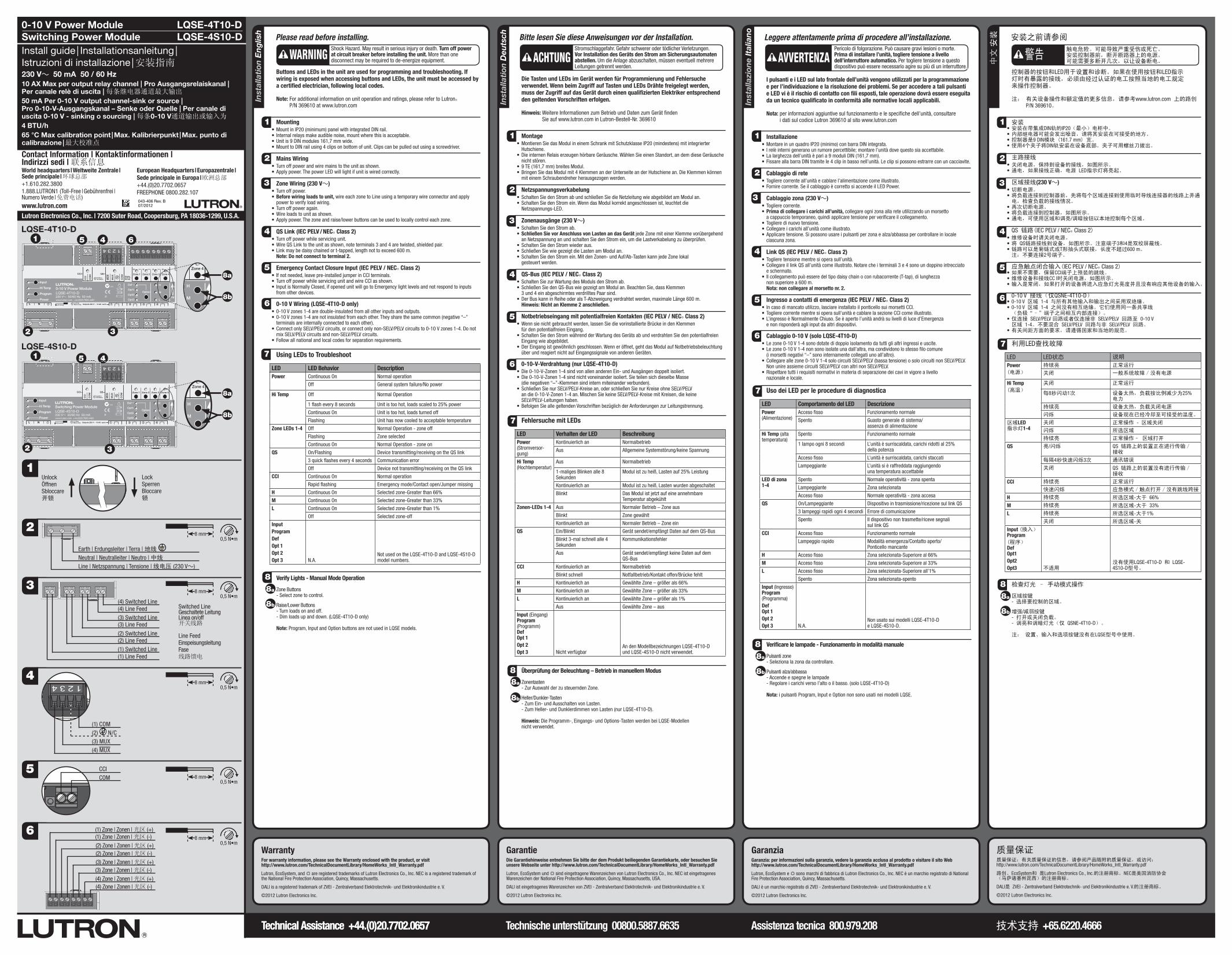
Please read before installing.Shock Hazard. May result in serious injury or death. Turn off power at circuit breaker before installing the unit. More than one disconnect may be required to de-energize equipment.WARNING
1
7 Using LEDs to Troubleshoot
LED LED Behavior DescriptionPower Continuous On Normal operation
Off General system failure/No power
Hi Temp Off Normal Operation
1 flash every 8 seconds Unit is too hot, loads scaled to 25% power
Continuous On Unit is too hot, loads turned off
Flashing Unit has now cooled to acceptable temperature
Zone LEDs 1-4 Off Normal Operation - zone off
Flashing Zone selected
Continuous On Normal Operation - zone on
QS On/Flashing Device transmitting/receiving on the QS link
3 quick flashes every 4 seconds Communication error
Off Device not transmitting/receiving on the QS link
CCI Continuous On Normal operation
Rapid flashing Emergency mode/Contact open/Jumper missing
H Continuous On Selected zone-Greater than 66%
M Continuous On Selected zone-Greater than 33%
L Continuous On Selected zone-Greater than 1%
Off Selected zone-off
Input ProgramDefOpt 1Opt 2Opt 3 N.A.
Not used on the LQSE-4T10-D and LQSE-4S10-D model numbers.
Verify Lights - Manual Mode Operation
Zone Buttons - Select zone to control.
Raise/Lower Buttons - Turn loads on and off. - Dim loads up and down. (LQSE-4T10-D only)
Note: Program, Input and Option buttons are not used in LQSE models.
3
Buttons and LEDs in the unit are used for programming and troubleshooting. If wiring is exposed when accessing buttons and LEDs, the unit must be accessed by a certified electrician, following local codes.
Note: For additional information on unit operation and ratings, please refer to LutronR P/N 369610 at www.lutron.com
Mounting•MountinIP20(minimum)panelwithintegratedDINrail.• Internalrelaysmakeaudiblenoise,mountwherethisisacceptable.•Unitis9DINmodules161,7mmwide.•MounttoDINrailusing4clipsonbottomofunit.Clipscanbepulledoutusingascrewdriver.
Mains Wiring•Turnoffpowerandwiremainstotheunitasshown.•Applypower.ThepowerLEDwilllightifunitiswiredcorrectly.
Zone Wiring (230 V~)•Turnoffpower.•Before wiring loads to unit, wire each zone to Line using a temporary wire connector and apply
power to verify load wiring.•Turnoffpoweragain.•Wireloadstounitasshown.•Applypower.Thezoneandraise/lowerbuttonscanbeusedtolocallycontroleachzone.
QS Link (IEC PELV / NECR Class 2)•Turnoffpowerwhileservicingunit.•WireQSLinktotheunitasshown,noteterminals3and4aretwisted,shieldedpair.• Linkmaybedaisychainedort-tapped,lengthnottoexceed600m. Note: Do not connect to terminal 2.
Emergency Contact Closure Input (IEC PELV / NECR Class 2)• Ifnotneeded,leavepre-installedjumperinCCIterminals.•TurnoffpowerwhileservicingunitandwireCCIasshown.• InputisNormallyClosed,ifopenedunitwillgotoEmergencylightlevelsandnotrespondtoinputs
from other devices.
0-10 V Wiring (LQSE-4T10-D only)•0-10Vzones1-4aredouble-insulatedfromallotherinputsandoutputs.•0-10Vzones1-4arenotinsulatedfromeachother.Theysharethesamecommon(negative“–”
terminals are internally connected to each other).•ConnectonlySELV/PELVcircuits,orconnectonlynon-SELV/PELVcircuitsto0-10 Vzones1-4.Donot
mix SELV/PELV circuits and non-SELV/PELV circuits.•Followallnationalandlocalcodesforseparationrequirements.
88a
8b
GaranziaGaranzia: per informazioni sulla garanzia, vedere la garanzia acclusa al prodotto o visitare il sito Web http://www.lutron.com/TechnicalDocumentLibrary/HomeWorks_Intl_Warranty.pdf
Lutron, EcoSystem e sono marchi di fabbrica di Lutron Electronics Co., Inc. NEC è un marchio registrato di National Fire Protection Association, Quincy, Massachusetts.
DALI è un marchio registrato di ZVEI - Zentralverband Elektrotechnik- und Elektronikindustrie e. V.
©2012 Lutron Electronics Inc.
GarantieDie Garantiehinweise entnehmen Sie bitte der dem Produkt beiliegenden Garantiekarte, oder besuchen Sie unsere Webseite unter http://www.lutron.com/TechnicalDocumentLibrary/HomeWorks_Intl_Warranty.pdf
Lutron, EcoSystem und sindeingetrageneWarenzeichenvonLutronElectronicsCo.,Inc.NECisteingetragenesWarenzeichenderNationalFireProtectionAssociation,Quincy,Massachusetts,USA.
DALIisteingetragenesWarenzeichenvonZVEI-ZentralverbandElektrotechnik-undElektronikindustriee.V.
©2012 Lutron Electronics Inc.
质量保证质量保证:有关质量保证的信息,请参阅产品随附的质量保证,或访问: http://www.lutron.com/TechnicalDocumentLibrary/HomeWorks_Intl_Warranty.pdf
路创、EcoSystem和 是Lutron Electronics Co., Inc.的注册商标。NEC是美国消防协会 (马萨诸塞州昆西)的注册商标。
DALI是 ZVEI - Zentralverband Elektrotechnik- und Elektronikindustrie e. V.的注册商标。
©2012 Lutron Electronics Inc.
Technical Assistance +44.(0)20.7702.0657 Technische unterstützung 00800.5887.6635 Assistenza tecnica 800.979.208 技术支持 +65.6220.4666
5
220 - 240 V~
6
MU
X
CO
M
MU
X
QS
Def
Opt1
Opt2
0-10 V Power ModuleLQSE-4T10-D230 V~ 50/60 Hz 50 mAwww.lutron.com +44.(0)20.7680.4481
1 2 3 4Outputs 230 V~ 10 AX each
Zone 1 Zone 2 Zone 3 Zone 4
Option
L N
µ
Z096
Opt3
CC
I
CCI
CO
M
0,5 N•mAll Others
8 mm1,2 N•mMains Only
Input
Hi Temp
Program
Power
H
M
L
Zones0-10 V-
50 mA
Up
3
2
MU
X
CO
M
MU
X
QS
Def
Opt1
Opt2
0-10 V Power ModuleLQSE-4T10-D230 V~ 50/60 Hz 50 mAwww.lutron.com +44.(0)20.7680.4481
1 2 3 4Outputs 230 V~ 10 AX each
Zone 1 Zone 2 Zone 3 Zone 4
Option
L N
µ
Z096
Opt3
CC
I
CCI
CO
M
0,5 N•mAll Others
8 mm1,2 N•mMains Only
Input
Hi Temp
Program
Power
H
M
L
Zones0-10 V-
50 mA
Up
Contact Information | Kontaktinformationen | Indirizzi sedi | 联系信息World headquarters | Weltweite Zentrale | Sede principale | 环球总部+1.610.282.38001.888.LUTRON1 (Toll-Free | Gebührenfrei | Numero Verde | 免费电话)www.lutron.com
European Headquarters | Europazentrale | Sede principale in Europa | 欧洲总部+44.(0)20.7702.0657FREEPHONE0800.282.107
CCICOM
1
4
220 - 240 V~
(1) COM(2) N/C
(4) MUX(3) MUX
0-10 V Power ModuleSwitching Power Module Install guide | Installationsanleitung | Istruzioni di installazione | 安装指南230 V~ 50 mA 50 / 60 Hz10 AX Max per output relay channel | Pro Ausgangsrelaiskanal | Per canale relè di uscita | 每条继电器通道最大输出
50 mA Per 0-10 V output channel-sink or source | Pro 0-10-V-Ausgangskanal – Senke oder Quelle | Per canale di uscita 0-10 V - sinking o sourcing | 每条0-10 V通道输出或输入为
4 BTU/h 65 °C Max calibration point | Max. Kalibrierpunkt | Max. punto di calibrazione | 最大校准点
043-406 Rev. B 07/2012
LQSE-4T10-DLQSE-4S10-D
LockSperrenBloccare锁
UnlockÖffnenSbloccare开锁
Technical Assistance +44.(0)20.7702.0657
MU
X
CO
M
MU
X
QS
Def
Opt1
Opt2
0-10 V Power ModuleLQSE-4T10-D230 V~ 50/60 Hz 50 mAwww.lutron.com +44.(0)20.7680.4481
1 2 3 4Outputs 230 V~ 10 AX each
Zone 1 Zone 2 Zone 3 Zone 4
Option
L N
µ
Z096
Opt3
CC
I
CCI
CO
M
0,5 N•mAll Others
8 mm1,2 N•mMains Only
Input
Hi Temp
Program
Power
H
M
L
Zones0-10 V-
50 mA
Up
(4) Line Feed
Line Feed Einspeisungsleitung Fase 线路馈电
(4) Switched LineSwitched Line Geschaltete Leitung Linea on/off 开关线路
(2) Switched Line
(3) Switched Line
(1) Switched Line(2) Line Feed
(3) Line Feed
(1) Line Feed
MU
X
CO
M
MU
X
QS
Def
Opt1
Opt2
Switching Power ModuleLQSE-4S10-D230 V~ 50/60 Hz 50 mAwww.lutron.com +44.(0)20.7680.4481
1 2 3 4Outputs 230 V~ 10 AX each
Zone 1 Zone 2 Zone 3 Zone 4
Option
L N
µ
Z096
Opt3
CC
I
CCI
CO
M
0,5 N•mAll Others
8 mm1,2 N•mMains Only
Input
Hi Temp
Program
Power
H
M
LUp
4
32
51
MU
X
CO
M
MU
X
QS
Def
Opt1
Opt2
0-10 V Power ModuleLQSE-4T10-D230 V~ 50/60 Hz 50 mAwww.lutron.com +44.(0)20.7680.4481
1 2 3 4Outputs 230 V~ 10 AX each
Zone 1 Zone 2 Zone 3 Zone 4
Option
L N
µ
Z096
Opt3
CC
I
CCI
CO
M
0,5 N•mAll Others
8 mm1,2 N•mMains Only
Input
Hi Temp
Program
Power
H
M
L
Zones0-10 V-
50 mA
Up
2
4 6
8a
8a
8b
8b
5
3
LQSE-4T10-D
LQSE-4S10-D
MU
X
CO
M
MU
X
QS
Def
Opt1
Opt2
0-10 V Power ModuleLQSE-4T10-D230 V~ 50/60 Hz 50 mAwww.lutron.com +44.(0)20.7680.4481
1 2 3 4Outputs 230 V~ 10 AX each
Zone 1 Zone 2 Zone 3 Zone 4
Option
L N
µ
Z096
Opt3
CC
I
CCI
CO
M
0,5 N•mAll Others
8 mm1,2 N•mMains Only
Input
Hi Temp
Program
Power
H
M
L
Zones0-10 V-
50 mA
Up
MU
X
CO
M
MU
X
QS
Def
Opt1
Opt2
0-10 V Power ModuleLQSE-4T10-D230 V~ 50/60 Hz 50 mAwww.lutron.com +44.(0)20.7680.4481
1 2 3 4Outputs 230 V~ 10 AX each
Zone 1 Zone 2 Zone 3 Zone 4
Option
L N
µ
Z096
Opt3
CC
I
CCI
CO
M
0,5 N•mAll Others
8 mm1,2 N•mMains Only
Input
Hi Temp
Program
Power
H
M
L
Zones0-10 V-
50 mA
Up
1
220 - 240 V~
0,5N•m8 mm
220 - 240 V~
0,5N•m8 mm
220 - 240 V~
0,5N•m8 mm
220 - 240 V~
0,5N•m8 mm
220 - 240 V~
0,5N•m8 mm
(1) Zone | Zonen | 光区 (+)(1) Zone | Zonen | 光区 (-)(2) Zone | Zonen | 光区 (+)(2) Zone | Zonen | 光区 (-)(3) Zone | Zonen | 光区 (+)(3) Zone | Zonen | 光区 (-)(4) Zone | Zonen | 光区 (+)(4) Zone | Zonen | 光区 (-)
Neutral | Neutralleiter | Neutro | 中线
Line | Netzspannung | Tensione | 线电压 (230 V~)
Earth | Erdungsleiter | Terra | 地线