Embed Size (px)
Citation preview
Boreal Europe BV, Thursday, August 23, 2012, Version 4
MANUEL D’UTILISATION Pour analyseur GasFinder
MODBUS TCP/IP MODULE
Pour numéros de référence: BOR01725, Modbus TCP/IP Module avec 1 port COM BOR01730, Modbus TCP/IP Module avec 2 ports COM
Boreal Europe BV Distributieweg 62 2645EJ Delfgauw The Netherlands www.boreal-laser.nl
Boreal Europe B.V. Serial Modbus Module manual April 2012
ii
CONTENTS 1. System Description ........................................................................................... Error! Bookmark not defined.
2. Implementing the “polled” data in the DCS / Scada ......................................... Error! Bookmark not defined.
2.1. Modbus Registers .............................................................................................................................. 1
2.2. Concentration Data (IN PPMM) ........................................................................................................ 1
2.3. Concentration Quality (in R2) ............................................................................................................ 2
2.4. Light Value ......................................................................................................................................... 2
2.5. DAC Value (only If ALC is enabled, see also 2.4)................................................................................ 2
2.6. SECONDS (WATCHDOG!) ................................................................................................................... 2
2.7. Status Code ....................................................................................................................................... 2
2.8. Diagnostic Data ................................................................................................................................. 3
3. Dimensions and physical specifications .......................................................................................................... 4
3.1. CE compliance ................................................................................................................................... 4
3.2. Immunity ........................................................................................................................................... 4
3.3. Emission ............................................................................................................................................ 4
3.4. Labels................................................................................................................................................. 4
3.5. Safety concerns in ATEX area’s.......................................................................................................... 5
4. Pre-installation checks .................................................................................................................................... 6
4.1. Tools and equipment ............................................................................................................................. 6
4.2. Equipment check ................................................................................................................................... 6
5. Installation ...................................................................................................................................................... 7
5.1. Connecting the GasFinder RS232 Output .............................................................................................. 7
5.2. Connecting the Modbus master to the TCP/IP Network ....................................................................... 7
5.3. Connecting the power supply ................................................................................................................ 7
6. Setting up Communication parameters .......................................................................................................... 8
6.1. Input; Between GasFinder and Module ................................................................................................. 8
6.2. Output; Between Modbus TCP/IP Module and the Modbus Master .................................................... 8
6.2.1. Configure the TCP/IP settings in the controller ................................................................................. 8
6.2.2. Using the IP changer Software .......................................................................................................... 9
6.2.3. Modbus registers ............................................................................................................................ 11
7. LED indication................................................................................................................................................ 12
7.1. LED Information explained .................................................................................................................. 12
A. Appendix ....................................................................................................................................................... 13
Boreal Europe BV, Thursday, August 23, 2012, Version 4
1. DESCRIPTION DU SYSTEM La Module Modbus TCP/IP est un appareil de type à être monté en rack. Elle permet l’utilisateur de
demander les données de l analyseur a l’aide du Protocol Modbus TCP/IP. Le maitre Modbus de l‘utilisateur
peut demander toutes les données disponibles de la module sur intervalles régulières. Le module converti les
données envoyées par l’analyseur et les sauvegardes en registres Modbus.
La Module Modbus TCP/IP est normalement équipée de 2 ports COM, chaque port est programmé pour
accepter les strings d’un GasFinder analyseur ou autre instrument conforme. Les deux ports COM utilisent
l’interface RS232 ce qui permet l’utilisation de un câble d’une longueur maximale de 10 mètre. La module est
conçue pour enregistres les données envoyées par deux GasFinder simultanément.
La Module utilise une interface RJ-45 UTP, ceci permet l’utilisation du protocole Modbus a travers un
réseaux UTP normal.
2. IMPLEMENTATION DES DONNEES DANS UN SYSTEM DSC / SCADA La plupart des applications ont leurs propres spécifications et implémentations. Toutefois ce manuel contient un guide universel indiquant les étapes nécessaire pour demander et interpréter les données de la module. Note : pour chaque appareil connecté les registres Modbus sont renouvelés quand l’appareil envoy u The data obtained by the Modbus Master, the users OPC server or DCS system has to be handled correctly. Most applications have their own needs and the implementation needs dedicated engineering. However, we hereunder give a guide how to implement the data within the DCS to obtain the maximum up time, minimize service and have the proper warnings and alarms. Note: For each connected channel the data is update in the registers when the GasFinder sends new data. Depending on the setting this can vary. Each channel is, with factory settings, in sequence updated in every 1.2 second.
2.1. MODBUS REGISTERS The data from the connected GasFinder(s) is stored in the holding registers. These registers have an address range of 40001 to 50000. Depending on which Modbus master software is used to read the holding registers of the Modbus controller the registers addresses have to be written differently (consult the user manual of the Modbus master software for the correct notation of the Modbus addresses). The values of the GFDTA, GFDBG and GFDAC strings are stored in the Modbus registers. The controller supports the input of the GasFinder MC, FC, OP and AB. Each time the Modbus controller receives a new string from the connected GasFinder the Modbus registers are updated. The Tables containing the Modbus register location can be found in Appendix A.
2.2. CONCENTRATION DATA (IN PPMM)
The concentration data is divided over two registers. The “ppmm” gives the concentration without decimals. This is sufficient for most applications. Example: Open path detection with a 100m pathlength will give an average path concentration divided by 100 to get a path average ppm level. A 1ppmm reading gives a path average of 1/100=0.01ppm. If alarm levels are 2ppm the accuracy is more than sufficient. No need to poll the decimal register. Example: A stack Ductprobe detection with a 2m pathlenght will give an average path concentration divided by 1 to get a path average ppm level. A 1ppmm reading gives a path average of 1/2=0.5ppm accuracy and minimum detection limit. In this case the decimal is needed to increase the accuracy with 1 decimal to 0.05ppm. If needed the decimal value can only be obtained if the concentration is below 100 or 10ppmm. This depending on the accuracy needed at high levels. The Modbus Master can make the decision.
Boreal Europe B.V. Serial Modbus Module manual April 2012
2
2.3. CONCENTRATION QUALITY (IN R2)
The concentration of the gas obtained by the analyser has a quality factor called R2. The R2 can be used to filter out low quality readings. Example: In a safety application the goal is to have an alarm when the concentration gets to a level that requires a warning or alarm to be set. Lower concentrations can be filtered out by simply setting a R2 filter on 50-80 (on the range to 0-100) Example: In an emission detection system even the lowest concentration and low quality readings are important. The R2 filter is not used.
2.4. LIGHT VALUE The functioning of a connected transmitter head or probe depends on the loop of energy. The loop starts with optical laser energy transported through a fiber to the probe. The probe aims the optical energy on the retro-reflector (mirror). The energy mirrored is reflected back into the probe and is focused on a photodiode. This diode transforms the optical energy into electrical energy. This energy is transported back through the coaxial return cable to the analyser. The level of energy returned is specified as “light level”. This light level should always be between a value of 2000-12000. Example if automatic Light Control is enabled: The lightvalue is always adjusted thus gives no real information. The DAC value should be used. Example if automatic Light Control is disabled: The value should be used as an indication for pollution of the optic system and is an indication for service. the value drops more than 30%, for longer than 30 minutes, for a particular channel (probe) preventive maintenance must be initiated. It can be planned in advance. Normally within 1-2 weeks is sufficient.
2.5. DAC VALUE (ONLY IF ALC IS ENABLED, SEE ALSO 2.4) The lightlevel can be automatically controlled (read; amplified and attenuated) by the analyser. However, when this is automated, by enabling the automatic light level option, the level stays corrected to the set level by the system. The correction is given by the DAC value. If the DAC value increases the probe needs more energy. This can be caused by higher humidity, steam, smoke or other influences in the “optical measurement path”. However it is also a good indication of pollution of the optics (The loop of energy!). When the DAC reaches the limit of 4095 the lightlevel will drop and cause low light errors. Example: When the DAC reaches 3000, for longer than 30 minutes, for a particular channel (probe) preventive maintenance must be initiated. It can be planned in advance. Normally within 1-2 weeks is sufficient.
2.6. SECONDS (WATCHDOG!) The second’s registers do function as a watchdog. In the case that something in the loop is “frozen” or stuck the seconds will not change. If the value of the seconds doesn’t change at every request of the Modbus Master a warning should be generated and the analyser must be inspected immediately. Data in the registers are not longer updated and are no longer actual!
2.7. STATUS CODE The Status Code gives all the accumulated errors within the analyser. The system has also a code when it is functioning properly. The code is either 1* or 9*. When the code is different than these all concentration data must be ignored for use as an alarm, warning or registration of the emission. Status code changes when servicing the analyser. However, when it changes during operation for A LONGER PERIOD THEN 5 MINUTES (and the system doesn’t give a normal status code after a stop/start) a Boreal Laser representative should be contacted!
Boreal Europe B.V. Serial Modbus Module manual April 2012
3
Example: The concentration is 546ppmm and this would generate an alarm. But the status code is 2048. Thus the reading must be ignored. Only the combination with a status code of 1* or 9* is a valid combination.
2.8. DIAGNOSTIC DATA Diagnostic data is available for each analyser. Requesting this data on a hourly base enhances the reliability of the system and minimizes the downtime. Values outside the accepted ranges require a service call by the nearest Boreal Laser Specialist. Historic data of these values can be send by email to help diagnose of the failure go faster. 1. Internal temperature Range 10-50 is accepted. 2. Duty Cycle Range between 100 – 200 is accepted. 3. Calibration Ratio Range of 4000 – 150000 is accepted. 4. Reference Cell Quality Range of 40-100 is accepted.
Boreal Europe B.V. Serial Modbus Module manual April 2012
4
3. DIMENSIONS AND PHYSICAL SPECIFICATIONS Weight (Grams) 7.4 K g Dimensions (L x W x H) 38 x 48.5 x 10 cm Humidity 5–95%, non-condensing Power requirements 100-240 VAC, 50Hz. Operation temperature range –40°C to +70°C Store rate (maximal) 2 samples / sec / each port Data output RJ45, Modbus RTU over TCP
3.1. CE COMPLIANCE
Equipment is usually divided into two classes.
Class A Class B
Digital equipment meant for light industrial use Digital equipment meant for home use
Less restrictive emission requirement: less than 40dB μV/m at 10m (40dB relative to 1 μV/m) or 300 μV/m
More restrictive emission requirements: 30dB μV/m at 10m or 100 μV/m
These limits apply over the range of 30–230 MHz. The limits are 7 dB higher for
frequencies above 230 MHz. Although the test range goes to 1 GHz, the
emissions from the Modbus TCP/IP Module systems at frequencies above 300
MHz are generally well below background noise levels.
The Modbus TCP/IP Module is CE compliant and therefore has the CE Mark.
3.2. IMMUNITY The Modbus TCP/IP Module meets the following EN55024/1998
immunity standards.
- EN61000-4-3 (Radiated Immunity)
- EN61000-4-4 (EFT)
EN61000-4-6 (Conducted immunity)
3.3. EMISSION
The Modbus TCP/IP Module meets the following emission standards.
- EN55022:1998 Class B
- FCC Part 15 Class B
3.4. LABELS
FIGUUR 1
Boreal Europe B.V. Serial Modbus Module manual April 2012
5
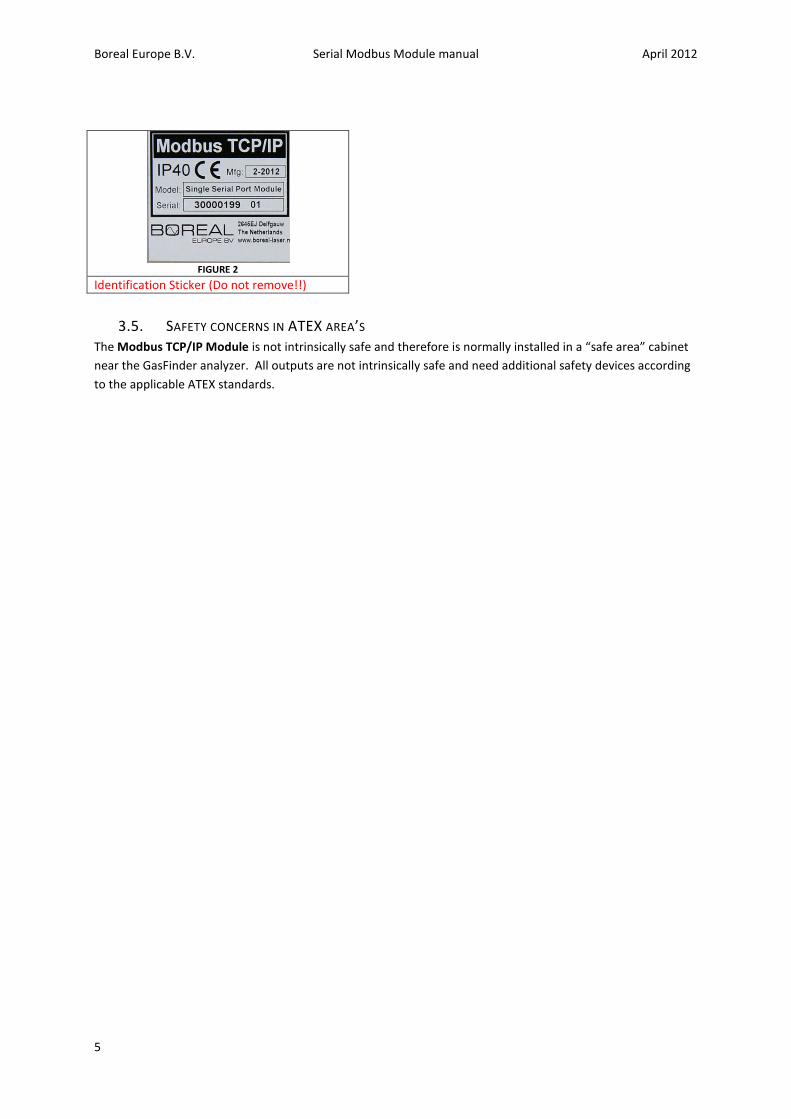
FIGURE 2
Identification Sticker (Do not remove!!)
3.5. SAFETY CONCERNS IN ATEX AREA’S The Modbus TCP/IP Module is not intrinsically safe and therefore is normally installed in a “safe area” cabinet
near the GasFinder analyzer. All outputs are not intrinsically safe and need additional safety devices according
to the applicable ATEX standards.
Boreal Europe B.V. Serial Modbus Module manual April 2012
6
4. PRE-INSTALLATION CHECKS Check the following points:
- Temperature limits; the Modbus TCP/IP Module should be located in an area where the temperature
does not go below –40°C or above +70°C.
- Power supply; the Modbus TCP/IP Module needs power, Voltage: 100 V to 240 VAC, 50Hz, 0.375 A
max.
- Accessibility; Acvces to the rear of the Modbus TCP/IP Module should be possible.
- Ventilation; Although the Module is highly efficient and generates minimum heat it needs some
ventilation to cool down the inner parts. Therefore a space around the unit of 50mm at the front, back
and sides are obliged. It can be horizontally stacked without space between other Boreal GasFinderMC
modules.
4.1. TOOLS AND EQUIPMENT
- Site specific personal protective equipment according to the local requirements.
- Set of assorted cable ties if cabling fixing is required.
- Set of screwdrivers.
4.2. EQUIPMENT CHECK
Verify that all the equipment on the order sheet has arrived complete and is in good condition. Any
damage due to shipping should be reported immediately and steps taken to obtain replacement parts.
Damaged Modules should be replaced immediately and are not allowed to be installed.
Boreal Europe B.V. Serial Modbus Module manual April 2012
7
5. INSTALLATION Note: Make sure that during the entire installation process that the TCP/IP Modbus Module is not
connected to any kind of power supply.
5.1. CONNECTING THE GASFINDER RS232 OUTPUT
Note: make sure the Serial communication cable is not connected to the GasFinder before
connecting it to the Module
There are one or two serial COM ports located on the module depending on the version. COM 1 and
an additional COM 2 can be found on the backpanel on the right hand side. A straight Dsub15 Cable is needed
to connect the GasFinder analyser to the Modbus TCP/IP module.
PIN Table
Serial COM port pin name COM Port pin number
TX COM 1 3
RX COM 1 2
Ground COM 1 5
TX COM 2 3
RX COM 2 2
Ground COM 2 5
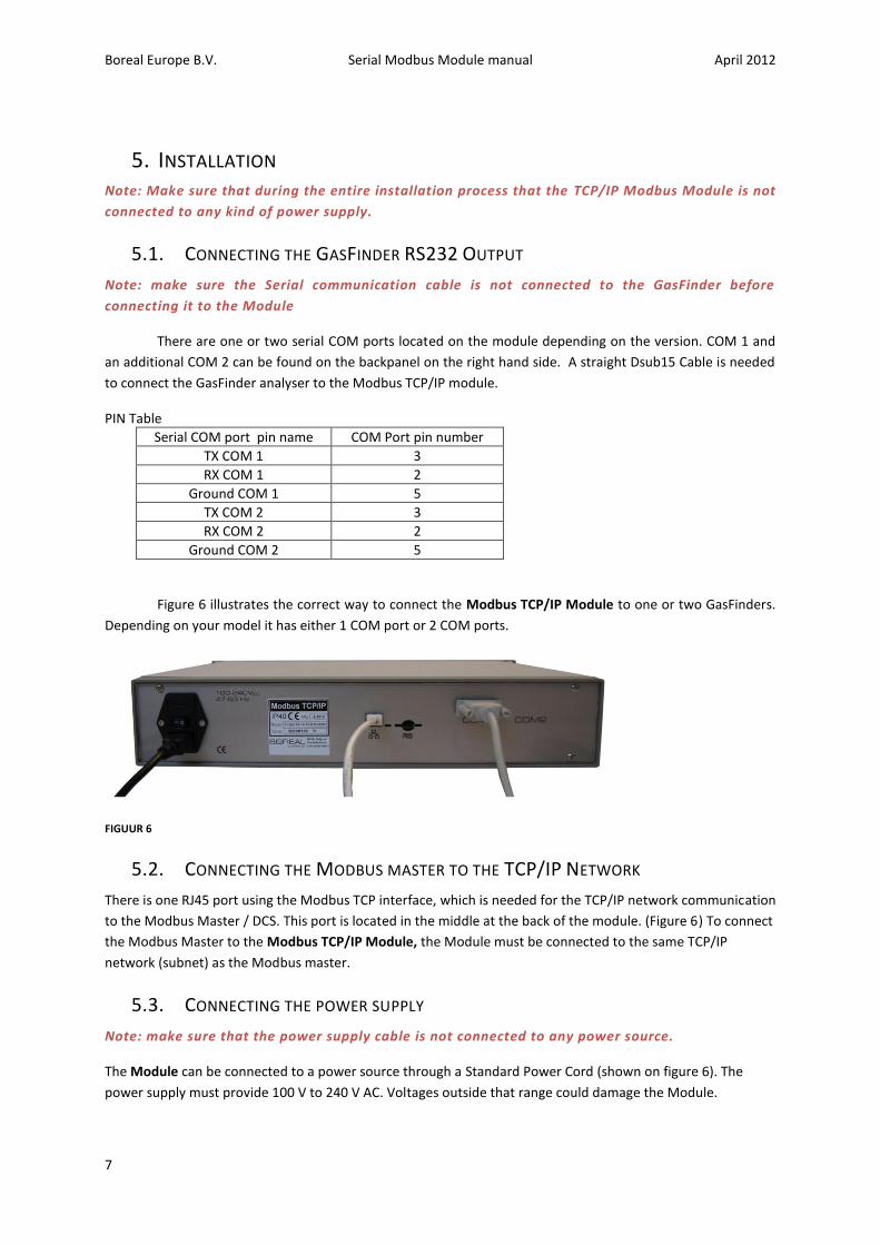
Figure 6 illustrates the correct way to connect the Modbus TCP/IP Module to one or two GasFinders.
Depending on your model it has either 1 COM port or 2 COM ports.
FIGUUR 6
5.2. CONNECTING THE MODBUS MASTER TO THE TCP/IP NETWORK
There is one RJ45 port using the Modbus TCP interface, which is needed for the TCP/IP network communication
to the Modbus Master / DCS. This port is located in the middle at the back of the module. (Figure 6) To connect
the Modbus Master to the Modbus TCP/IP Module, the Module must be connected to the same TCP/IP
network (subnet) as the Modbus master.
5.3. CONNECTING THE POWER SUPPLY
Note: make sure that the power supply cable is not connected to any power source.
The Module can be connected to a power source through a Standard Power Cord (shown on figure 6). The
power supply must provide 100 V to 240 V AC. Voltages outside that range could damage the Module.
Boreal Europe B.V. Serial Modbus Module manual April 2012
8
6. SETTING UP COMMUNICATION PARAMETERS
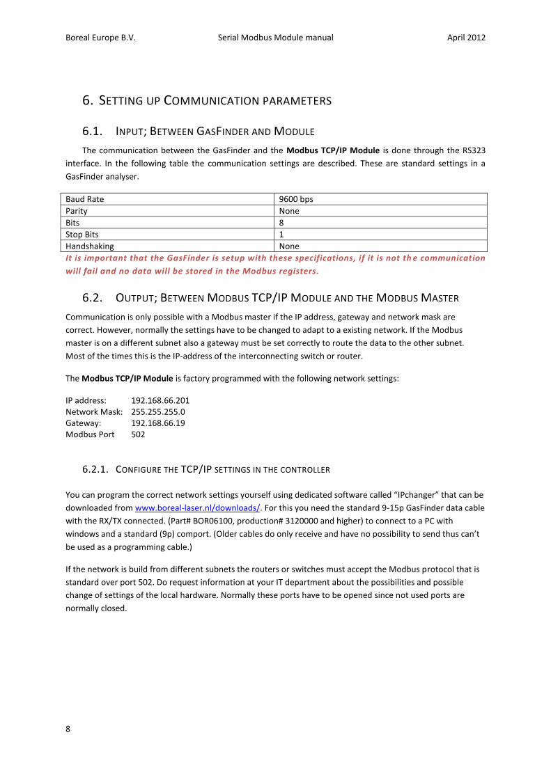
6.1. INPUT; BETWEEN GASFINDER AND MODULE
The communication between the GasFinder and the Modbus TCP/IP Module is done through the RS323
interface. In the following table the communication settings are described. These are standard settings in a
GasFinder analyser.
Baud Rate 9600 bps
Parity None
Bits 8
Stop Bits 1
Handshaking None
It is important that the GasFinder is setup with these specifications, if it is not th e communication
will fail and no data will be stored in the Modbus registers.
6.2. OUTPUT; BETWEEN MODBUS TCP/IP MODULE AND THE MODBUS MASTER
Communication is only possible with a Modbus master if the IP address, gateway and network mask are
correct. However, normally the settings have to be changed to adapt to a existing network. If the Modbus
master is on a different subnet also a gateway must be set correctly to route the data to the other subnet.
Most of the times this is the IP-address of the interconnecting switch or router.
The Modbus TCP/IP Module is factory programmed with the following network settings:
IP address: 192.168.66.201 Network Mask: 255.255.255.0 Gateway: 192.168.66.19 Modbus Port 502
6.2.1. CONFIGURE THE TCP/IP SETTINGS IN THE CONTROLLER
You can program the correct network settings yourself using dedicated software called “IPchanger” that can be
downloaded from www.boreal-laser.nl/downloads/. For this you need the standard 9-15p GasFinder data cable
with the RX/TX connected. (Part# BOR06100, production# 3120000 and higher) to connect to a PC with
windows and a standard (9p) comport. (Older cables do only receive and have no possibility to send thus can’t
be used as a programming cable.)
If the network is build from different subnets the routers or switches must accept the Modbus protocol that is
standard over port 502. Do request information at your IT department about the possibilities and possible
change of settings of the local hardware. Normally these ports have to be opened since not used ports are
normally closed.
Boreal Europe B.V. Serial Modbus Module manual April 2012
9
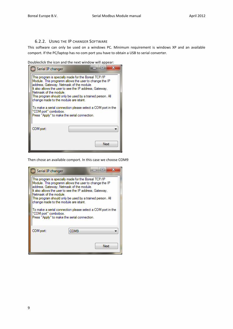
6.2.2. USING THE IP CHANGER SOFTWARE This software can only be used on a windows PC. Minimum requirement is windows XP and an available
comport. If the PC/laptop has no com port you have to obtain a USB to serial converter.
Doubleclick the icon and the next window will appear:
Then chose an available comport. In this case we choose COM9
Boreal Europe B.V. Serial Modbus Module manual April 2012
10
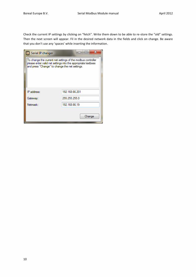
Check the current IP settings by clicking on “fetch”. Write them down to be able to re-store the “old” settings.
Then the next screen will appear. Fil in the desired network data in the fields and click on change. Be aware
that you don’t use any ‘spaces’ while inserting the information.
Boreal Europe B.V. Serial Modbus Module manual April 2012
11
6.2.3. MODBUS REGISTERS The data from the connected GasFinder(s) is stored in the holding registers. These registers have an address
range of 40001 to 50000. Depending on which Modbus master software is used to read the holding registers of
the Modbus TCP/IP Module the registers addresses have to be written differently (consult the user manual of
the Modbus master software for the correct notation of the Modbus addresses). This is mainly due to the fact
that some program start counting at ‘0’ and others start counting at ‘1’. Or some programs want the user to
specify which type of register needs to be polled in the register number (4 is holding register and 3 is input
register). This may give some problems trying to configure the Modbus master because the polled values will
shift by one position.
Here are some notations which in different programs give the same register, for this example register 1234
from the holding registers will be used:
Register[1234] Modbus master A polling address(41234)
Register[1234] Modbus master B polling address(401234)
Register[1234] Modbus master A polling address(41235)
Register[1234] Modbus master A polling address(1235)
Because many programs use a different notation it is advised to check if the register values are correct
before programming them into the Modbus Master.
The values of the GFDTA, GFDBG and GFDAC strings are stored in the Modbus registers. The Module supports
the input of the GasFinder MC, FC, OP and AB. Each time the Modbus TCP/IP Module receives a new string
from the connected GasFinder the Modbus registers are updated.
The Tables containing the Modbus register locations can be found in Appendix A.
Boreal Europe B.V. Serial Modbus Module manual April 2012
12
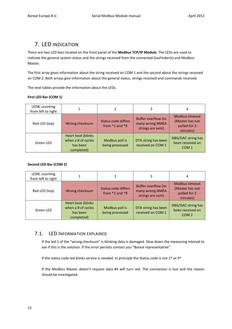
7. LED INDICATION There are two LED bars located on the front panel of the Modbus TCP/IP Module. The LEDs are used to
indicate the general system status and the strings received from the connected GasFinder(s) and Modbus
Master.
The first array gives information about the string received on COM 1 and the second about the strings received
on COM 2. Both arrays give information about the general status, strings received and commands received.
The next tables provide the information about the LEDs.
First LED Bar (COM 1)
LED#, counting from left to right
1 2 3 4
Red LED (top) Wrong checksum Status code differs
from *1 and *9
Buffer overflow (to many wrong NMEA
strings are sent)
Modbus timeout (Master has not
polled for 2 minutes)
Green LED
Heart beat (blinks when a # of cycles
has been completed)
Modbus poll is being processed
DTA string has been received on COM 1
DBG/DAC string has been received on
COM 1
Second LED Bar (COM 2)
LED#, counting from left to right
1 2 3 4
Red LED (top) Wrong checksum Status code differs
from *1 and *9
Buffer overflow (to many wrong NMEA
strings are sent)
Modbus timeout (Master has not
polled for 2 minutes)
Green LED
Heart beat (blinks when a # of cycles
has been completed)
Modbus poll is being processed
DTA string has been received on COM 2
DBG/DAC string has been received on
COM 2
7.1. LED INFORMATION EXPLAINED
If the led 1 of the “wrong checksum” is blinking data is damaged. Slow down the measuring interval to
see if this is the solution. If the error persists contact you “Boreal representative”.
If the status code led blinks service is needed. In principle the Status code is not 1* or 9*
If the Modbus Master doesn’t request data #4 will turn red. The connection is lost and the reason
should be investigated.
Boreal Europe B.V. Serial Modbus Module manual April 2012
13
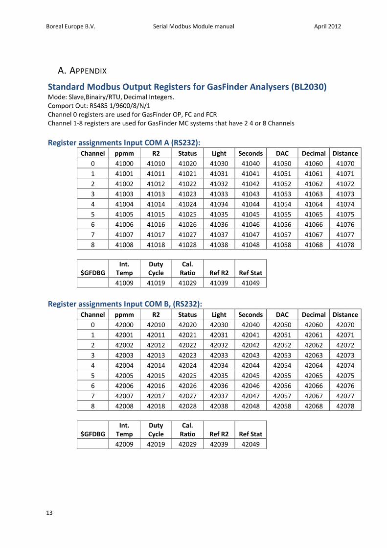
A. APPENDIX
Standard Modbus Output Registers for GasFinder Analysers (BL2030) Mode: Slave,Binairy/RTU, Decimal Integers. Comport Out: RS485 1/9600/8/N/1 Channel 0 registers are used for GasFinder OP, FC and FCR Channel 1-8 registers are used for GasFinder MC systems that have 2 4 or 8 Channels
Register assignments Input COM A (RS232):
Channel ppmm R2 Status Light Seconds DAC Decimal Distance
0 41000 41010 41020 41030 41040 41050 41060 41070
1 41001 41011 41021 41031 41041 41051 41061 41071 2 41002 41012 41022 41032 41042 41052 41062 41072 3 41003 41013 41023 41033 41043 41053 41063 41073 4 41004 41014 41024 41034 41044 41054 41064 41074 5 41005 41015 41025 41035 41045 41055 41065 41075 6 41006 41016 41026 41036 41046 41056 41066 41076 7 41007 41017 41027 41037 41047 41057 41067 41077 8 41008 41018 41028 41038 41048 41058 41068 41078
$GFDBG
Int. Temp
Duty Cycle
Cal. Ratio Ref R2 Ref Stat
41009 41019 41029 41039 41049
Register assignments Input COM B, (RS232):
Channel ppmm R2 Status Light Seconds DAC Decimal Distance
0 42000 42010 42020 42030 42040 42050 42060 42070
1 42001 42011 42021 42031 42041 42051 42061 42071 2 42002 42012 42022 42032 42042 42052 42062 42072 3 42003 42013 42023 42033 42043 42053 42063 42073 4 42004 42014 42024 42034 42044 42054 42064 42074 5 42005 42015 42025 42035 42045 42055 42065 42075 6 42006 42016 42026 42036 42046 42056 42066 42076 7 42007 42017 42027 42037 42047 42057 42067 42077 8 42008 42018 42028 42038 42048 42058 42068 42078
$GFDBG
Int. Temp
Duty Cycle
Cal. Ratio Ref R2 Ref Stat
42009 42019 42029 42039 42049
Boreal Europe B.V. Serial Modbus Module manual April 2012
14
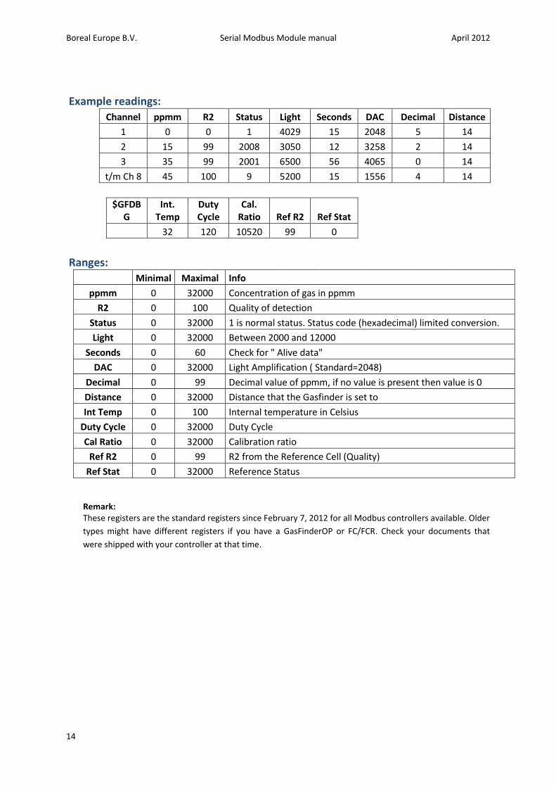
Example readings:
Channel ppmm R2 Status Light Seconds DAC Decimal Distance
1 0 0 1 4029 15 2048 5 14
2 15 99 2008 3050 12 3258 2 14
3 35 99 2001 6500 56 4065 0 14
t/m Ch 8 45 100 9 5200 15 1556 4 14
$GFDBG
Int. Temp
Duty Cycle
Cal. Ratio Ref R2 Ref Stat
32 120 10520 99 0
Ranges:
Minimal Maximal Info
ppmm 0 32000 Concentration of gas in ppmm
R2 0 100 Quality of detection
Status 0 32000 1 is normal status. Status code (hexadecimal) limited conversion.
Light 0 32000 Between 2000 and 12000
Seconds 0 60 Check for " Alive data"
DAC 0 32000 Light Amplification ( Standard=2048)
Decimal 0 99 Decimal value of ppmm, if no value is present then value is 0
Distance 0 32000 Distance that the Gasfinder is set to
Int Temp 0 100 Internal temperature in Celsius
Duty Cycle 0 32000 Duty Cycle
Cal Ratio 0 32000 Calibration ratio
Ref R2 0 99 R2 from the Reference Cell (Quality)
Ref Stat 0 32000 Reference Status
Remark: These registers are the standard registers since February 7, 2012 for all Modbus controllers available. Older
types might have different registers if you have a GasFinderOP or FC/FCR. Check your documents that
were shipped with your controller at that time.