Embed Size (px)
Citation preview
SVEUČILIŠTE U DUBROVNIKU
POMORSKI ODJEL
PREDDIPLOMSKI STUDIJ BRODOSTROJARSTVO
MARINE ENGINEERING COURSE
Priredila: mr. sc. Nives Vidak, prof.
Dubrovnik, 2016

RECENZENTI:
dr. sc. Helena Brautović, viša predavačica
mr. sc. Ivana Nakić Lučić, viša predavačica
dr. sc. Mate Jurjević, docent
ISBN 978-953-7153-40-3 (Sveučilište u Dubrovniku)
Izdavač:
Sveučilište u Dubrovniku
Branitelja Dubrovnika 29, 20000 Dubrovnik
http://www.unidu.hr
Grafička priprema:
Davorka Turčinović, mag. oec.
CONTENTS
1. CLASSIFICATION SOCIETIES ............................................................................................... 1
2. HOW MERCHANT SHIPS OPERATE .................................................................................... 3
2.1 TYPES OF MERCHANT SHIPS ....................................................................................... 4
3. SHIP CONSTRUCTION ......................................................................................................... 5
3.1 TERMS RELATING TO THE HULL .................................................................................. 6
4. SHIPBOARD DIRECTIONS AND LOCATIONS ....................................................................... 9
5. THE ORGANISATION OF A SHIP’S CREW .......................................................................... 10
5.1 THE DECK DEPARTMENT ........................................................................................... 10
5.2 THE ENGINE DEPARTMENT ....................................................................................... 12
6. UMS OPERATION ............................................................................................................. 13
7. PERIODIC SAFETY ROUTINES ........................................................................................... 14
8. SHIP’S EQUIPMENT .......................................................................................................... 15
8.1 AUXILIARY MACHINERY ............................................................................................ 16
8.2 MAIN ENGINES .......................................................................................................... 17
8.2.1 DIESEL ENGINE ................................................................................................ 17
8.2.2 STEAM TURBINE ............................................................................................. 19
8.2.3 GAS TURBINE .................................................................................................. 19
8.2.4 NUCLEAR PLANT ............................................................................................. 20
9. STEAM TURBINES ............................................................................................................ 21
9.1 TURBINE TYPES ......................................................................................................... 22
9.2 TURBINE CONSTRUCTION ......................................................................................... 23
9.3 TURBINE CONTROL ................................................................................................... 24
9.4 TURBINE PROTECTION .............................................................................................. 24
10. THE MAIN TYPES OF SHIP PROPULSION SYSTEMS ......................................................... 26
10.1 DIRECT DRIVE PROPULSION SYSTEM ...................................................................... 26
10.2 GEARED DRIVE PROPULSTION SYSTEM .................................................................. 26
10.3 ELECTRICAL PROPULSION SYSTEM ......................................................................... 27
11. BASIC MATHEMATICAL SYMBOLS ................................................................................. 28

12. ENGINEERING MATERIALS ............................................................................................. 30
12.1 PROPERTIES OF ENGINEERING MATERIALS ............................................................ 31
13. CORROSION ................................................................................................................... 33
14. MECHANISMS ................................................................................................................ 35
15. PISTONS ......................................................................................................................... 36
16. FORCES IN ENGINEERING .............................................................................................. 38
17. LUBRICATION ................................................................................................................. 39
18. COOLING ........................................................................................................................ 40
19. BOILERS .......................................................................................................................... 42
19.1 BOILER TYPES .......................................................................................................... 43
19.1.1 WATER-TUBE BOILERS .................................................................................. 44
19.1.2 FIR-TUBE BOILERS ......................................................................................... 44
19.2 BOILER MOUNTINGS ............................................................................................... 45
19.3 BOILER MOUNTINGS (WATER-TUBE BOILERS) ....................................................... 46
20. GENERATORS ................................................................................................................. 47
21. SAFE WORKING PRACTICES ........................................................................................... 49
22. TOOLS AND ACCESSORIES ............................................................................................. 51
23. REFERENCES .................................................................................................................. 55
24. LIST OF TABLES AND FIGURES ....................................................................................... 56
MARINE ENGINEERING COURSE mr. sc. NIVES VIDAK, prof.
1
1. CLASSIFICATION SOCIETIES
Every ship is designed and constructed to the certain class and is operated in the conditions
related to the given class. Class means the character assigned to a vessel by a classification
society, depending on the design of the vessel, the quality of materials employed, the scantlings
of the various structural members, and the outfit and equipment, all of which should be up to
the standard specified by the society's rules. To ensure that the condition and seaworthiness of
classed ships are maintained they are examined periodically and the continuance of the class
depends upon the result of such survey.
Classification society is a special institution which has as its purpose supervision of vessels
during their construction and afterwards, in respect to their seaworthiness and upkeep, and the
placing of vessels in grades or "classes" according to the society's rules for each particular type
of vessel. The principle classification societies are: Lloyd's Register of Shipping, London;
American Bureau of Shipping, New York; Bureau Veritas, Paris; Germanischer Lloyd, Berlin; Det
Norske Veritas, Oslo; Japanese Marine Corporation, Tokyo; Russian Maritime Register of
Shipping, St. Petersburg. Lloyd's Register of Shipping is the largest and oldest British
classification society, established in 1834. In Croatia there is the Croatian Register of Shipping
(Hrvatski registar brodova).
Classification societies are known to have a profound influence on shipping, ship design and
ship safety. The fundamental purpose of classification is to ensure maintenance of
seaworthiness of all classed ships. Withdrawal of a class means cessation of the Register
supervision when renewal of a class seems impossible for the Register. The class might be
withdrawn by the Register at the shipowner's desire as well. The Classification societies operate
throughout the world and publish rules and regulations directly related to the structural
efficiency of the ship and reliability of the propelling machinery. Classification implies the ship
and the machinery conform to the standards published in the rules of the Society.
The societies' rules are not absolutely rigid in every detail, as the progress of shipbuilding
methods and materials makes it necessary that a certain amount of latitude be allowed. They
represent the minimum standards which the society considers necessary for a particular type of
vessel. In classed vessels the materials and the actual construction are under the supervision of
the society's surveyors. At completion of the building and after trials at sea, classification
certificates are issued and handed to the owners.
MARINE ENGINEERING COURSE mr. sc. NIVES VIDAK, prof.
2
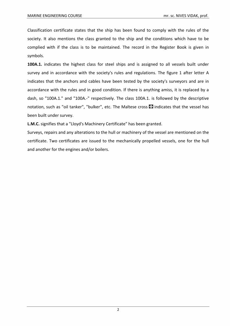
Classification certificate states that the ship has been found to comply with the rules of the
society. It also mentions the class granted to the ship and the conditions which have to be
complied with if the class is to be maintained. The record in the Register Book is given in
symbols.
100A.1. indicates the highest class for steel ships and is assigned to all vessels built under
survey and in accordance with the society's rules and regulations. The figure 1 after letter A
indicates that the anchors and cables have been tested by the society's surveyors and are in
accordance with the rules and in good condition. If there is anything amiss, it is replaced by a
dash, so "100A.1." and "100A.-" respectively. The class 100A.1. is followed by the descriptive
notation, such as "oil tanker", "bulker", etc. The Maltese cross indicates that the vessel has
been built under survey.
L.M.C. signifies that a "Lloyd's Machinery Certificate" has been granted.
Surveys, repairs and any alterations to the hull or machinery of the vessel are mentioned on the
certificate. Two certificates are issued to the mechanically propelled vessels, one for the hull
and another for the engines and/or boilers.
MARINE ENGINEERING COURSE mr. sc. NIVES VIDAK, prof.
3
2. HOW MERCHANT SHIPS OPERATE
Merchant vessels can operate in the following three basic ways:
They can operate as liners. These are employed on regular routes on a fixed timetable. A list of
their arrival and departure dates is published in advance and they sail whether they are full or
not. Liners can be classed as either deep-sea liners or short-sea liners. Ferries are also classed as
liners. These offer a daily or weekly service for passengers and vehicles across channels and
narrow seas. A few ships are still employed as passenger liners. They not only carry passengers
but also some cargo on routes from Europe to North America and to the Far East. Nowadays the
passenger trade is very small and passenger liners usually operate as cruise ships for part of the
year.
Merchant ships can also operate as tramps. These vessels do not sail on regular routes or keep
to a fixed timetable, but are employed where there is cargo for them to carry. Coasters are also
tramps and these ply on coastal routes and up rivers to inland ports. The traditional tramp
cargoes are dry bulk cargoes, but some vessels are designed to carry general cargoes.
A large number of merchant ships operate as specialised vessels. These are designed to carry a
particular type of cargo. There are several types of specialised vessel. The most common are oil
tankers. They are owned by the major oil companies or by independent operators. Two other
types of liquid bulk carrier of growing importance are chemical carriers and liquefied natural gas
(LNG) carriers.
2.1 TYPES OF MERCHANT SHIPS
Merchant ships can be classified according to what they carry. Most are designed to carry cargo.
Some are also designed to carry passengers.
Cargo ships can be divided into two basic types. One type carries dry cargo, the other carries
liquid cargo; however an OBO ship is designed to carry both. A traditional dry cargo ship is the
multi-deck vessel. Her holds are divided horizontally by one or two 'tween decks, because these
make stowage of individual packages easier. Dry bulk cargo is carried in bulk carriers. These do
not have 'tween decks as cargo is carried loose. The most modern type of dry cargo carrier is
the container ship. They carry containers of standard dimensions, consequently stowage is
easier. Fruit, meat and dairy produce are carried in refrigerated ships. Oil tankers are the most
common type of liquid cargo carrier. They are often very large, because huge quantities of oil
need to be transported and one large vessel is more economical to operate than two smaller
MARINE ENGINEERING COURSE mr. sc. NIVES VIDAK, prof.
4
ones. Two other types of liquid bulk carrier of growing importance are the liquefied natural gas
(LNG) carrier and the chemical carrier, although chemicals can also be carried in drums in
general cargo ships.
In comparison with cargo vessels, passenger ships are fewer in number and type. The traditional
passenger ship is the passenger liner. Nowadays their number has been greatly reduced,
because of competition from air transport. Another type of passenger vessel is the cruise ship.
These are similar in appearance to passenger liners. The most common type of passenger vessel
is the ferry. Many of them are also designed to carry vehicles, therefore these have doors at the
stern or bows.
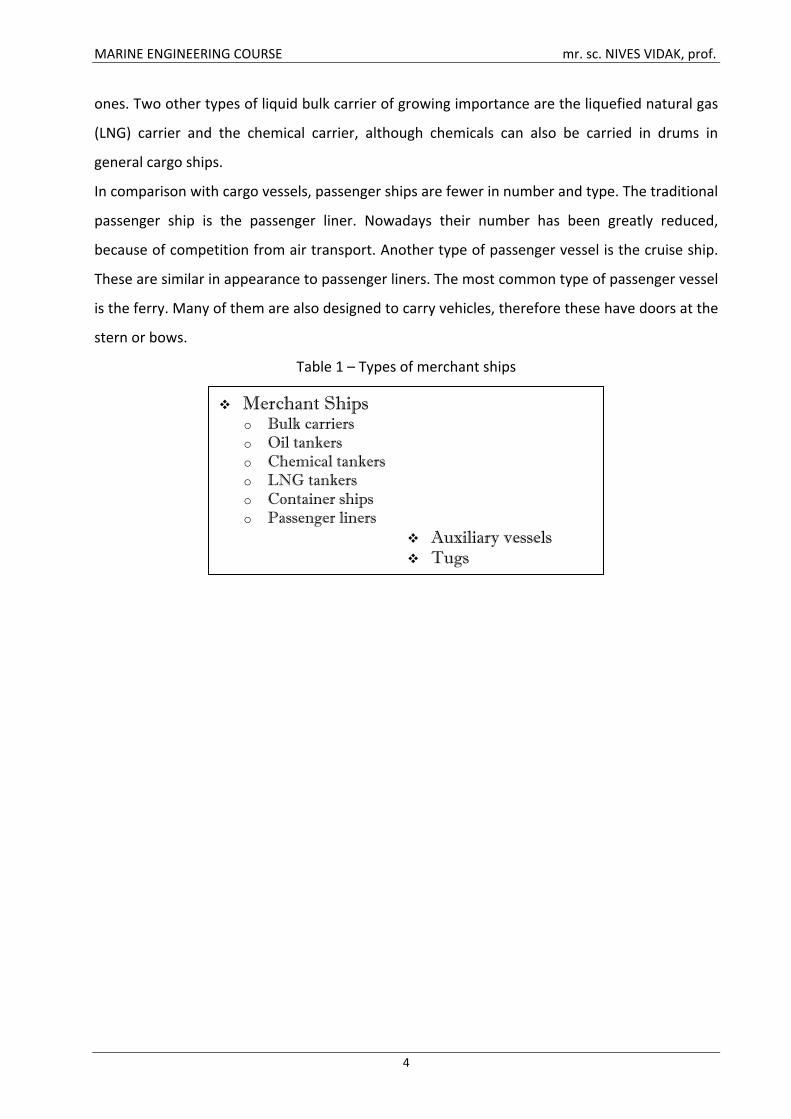
Table 1 – Types of merchant ships
Merchant Shipso Bulk carriers o Oil tankers o Chemical tankers o LNG tankers o Container ships o Passenger liners
Auxiliary vessels Tugs
MARINE ENGINEERING COURSE mr. sc. NIVES VIDAK, prof.
5
3. SHIP CONSTRUCTION
Ships are large, complex units which must be self-sustaining in their environment for long
periods with a high degree of reliability. A ship is the product of two main areas of skill, those of
the naval architect and the marine engineer. The naval architect is concerned with the hull, its
construction, form, habitability and ability to endure its environment. The marine engineer is
responsible for the various systems which propel and operate the ship. More specifically, this
means the machinery required for propulsion, steering, anchoring and ship securing, cargo
handling, air conditioning, power generation and its distribution. Some overlap in
responsibilities occurs between naval architects and marine engineers in areas such as propeller
design, the reduction of noise and vibration in the ship's structure, and engineering services
provided to considerable areas of the ship.
A ship may be divided into three distinct areas: the cargo-carrying holds or tanks, the
accommodation and the machinery space. Depending upon the type each ship will assume
varying proportions and functions. An oil tanker, for instance, will have the cargo-carrying
region divided into tanks by two longitudinal bulkheads and several transverse bulkheads. There
will be considerable quantities of cargo piping both above and below decks. The general cargo
ship will have various cargo holds which are usually the full width of the vessel and formed by
transverse bulkheads along the ship's length. Cargo handling equipment will be arranged on
deck and there will be large hatch openings closed with steel hatch covers. The accommodation
areas in each of these ship types will be sufficient to meet the requirements for the ship's crew,
provide a navigating bridge area and a communications centre. The machinery space size will be
decided by the particular machinery installed and the auxiliary equipment necessary. A
passenger ship, however, would have a large accommodation area, since this might be
considered the 'cargo space'. Machinery space requirements will probably be larger because of
air conditioning equipment, stabilisers and other passenger related equipment.
3.1 TERMS RELATING TO THE HULL
The hull is the main body of the ship below the main outside deck. The hull consists of an
outside covering (or shell plating) and an inside framework to which the plating is secured. The
plating and framework are usually made of steel and secured by welding. However, there may
still be some areas where rivets are used.
MARINE ENGINEERING COURSE mr. sc. NIVES VIDAK, prof.
6
If the coatings applied to the hulls of modern commercial vessels are maintained, they act as a
deterrent to the settlement of marine organisms on vessel surfaces below the water line.
Studies have shown that there are areas on the hull where the coatings are compromised, thus
allowing settlement of marine fouling organisms. Fouling organisms have also been noted to
exist in sheltered areas around rudder posts, and within sea chest intakes.
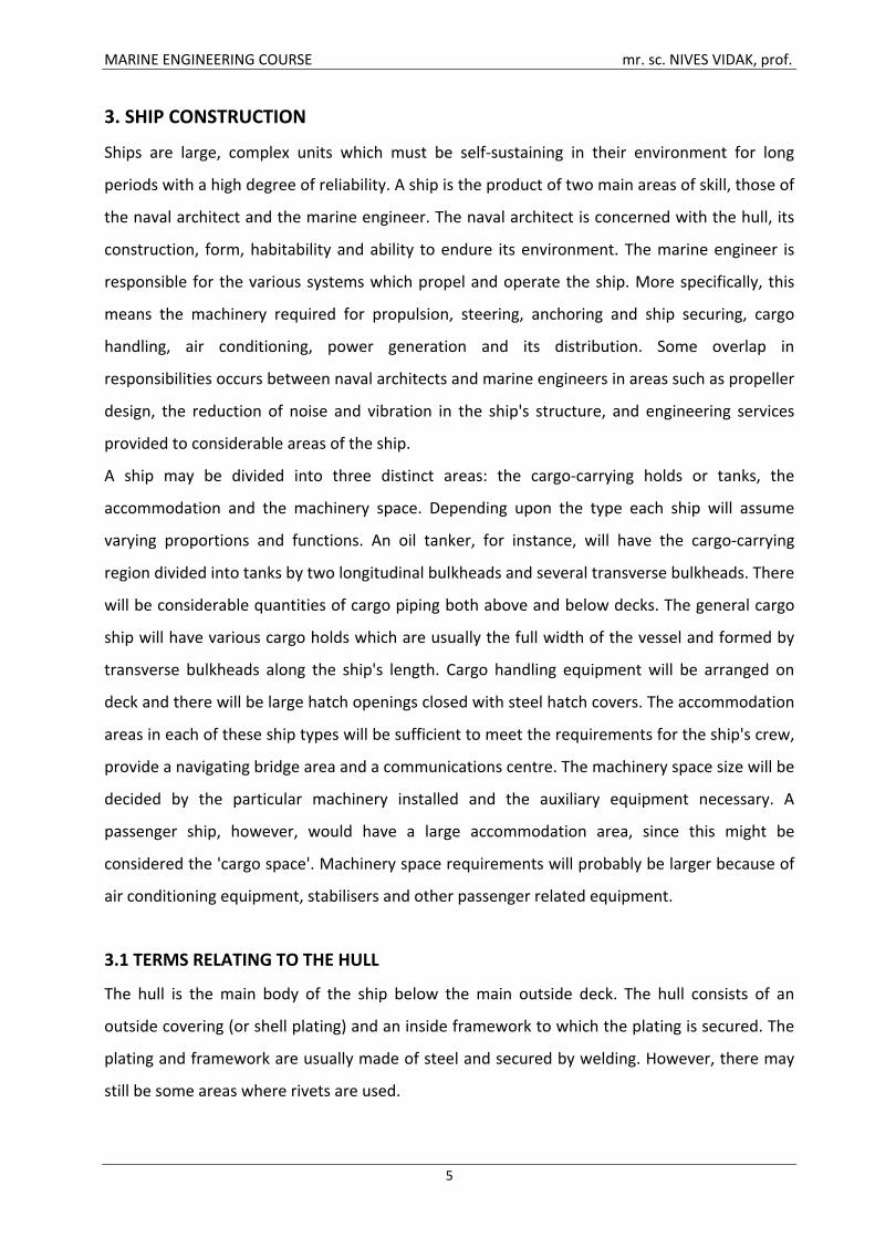
The main centreline structural part of the hull is the keel, which runs from the stem at the bow
to the sternpost at the stern. The keel is the backbone of the ship. To the keel are fastened the
frames, which run athwartships. These are the ribs of the ship and give shape and strength to
the hull. Deck beams and bulkheads support the decks and give added strength to resist the
pressure of the water on the sides of the hull.
Figure 1 – Construction of a hull
SHELL PLATING
The shell plating provides water-tightness. The plates, the principal strength members of a ship,
have various thickness. The heaviest plates are put on amidships. The others are put on so that
they taper toward both ends of the ship (from the keel toward the bilge and from the bilge
toward the upper row of plates). Using plates of various thickness reduces the weight of the
metal used and gives the vessel additional strength at its broadest part. The plates, put on in
MARINE ENGINEERING COURSE mr. sc. NIVES VIDAK, prof.
7
rows from bow to stern, are called strakes. They are lettered consecutively, beginning at the
keel and going upward.
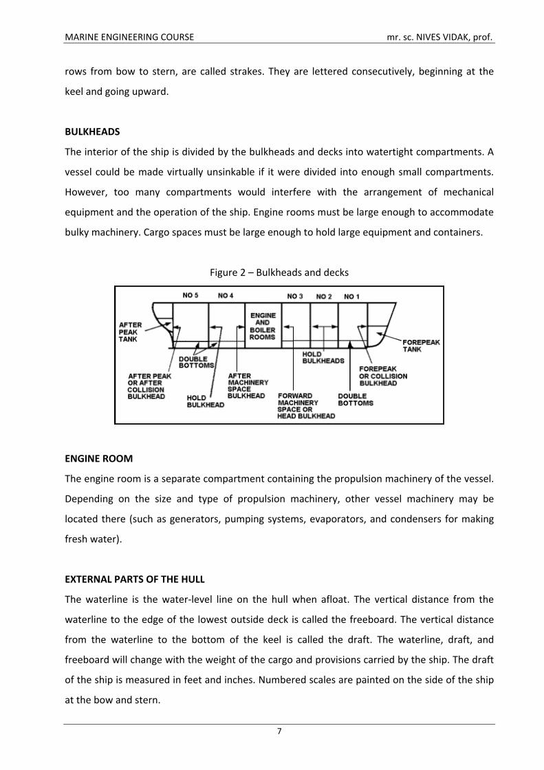
BULKHEADS
The interior of the ship is divided by the bulkheads and decks into watertight compartments. A
vessel could be made virtually unsinkable if it were divided into enough small compartments.
However, too many compartments would interfere with the arrangement of mechanical
equipment and the operation of the ship. Engine rooms must be large enough to accommodate
bulky machinery. Cargo spaces must be large enough to hold large equipment and containers.
Figure 2 – Bulkheads and decks
ENGINE ROOM
The engine room is a separate compartment containing the propulsion machinery of the vessel.
Depending on the size and type of propulsion machinery, other vessel machinery may be
located there (such as generators, pumping systems, evaporators, and condensers for making
fresh water).
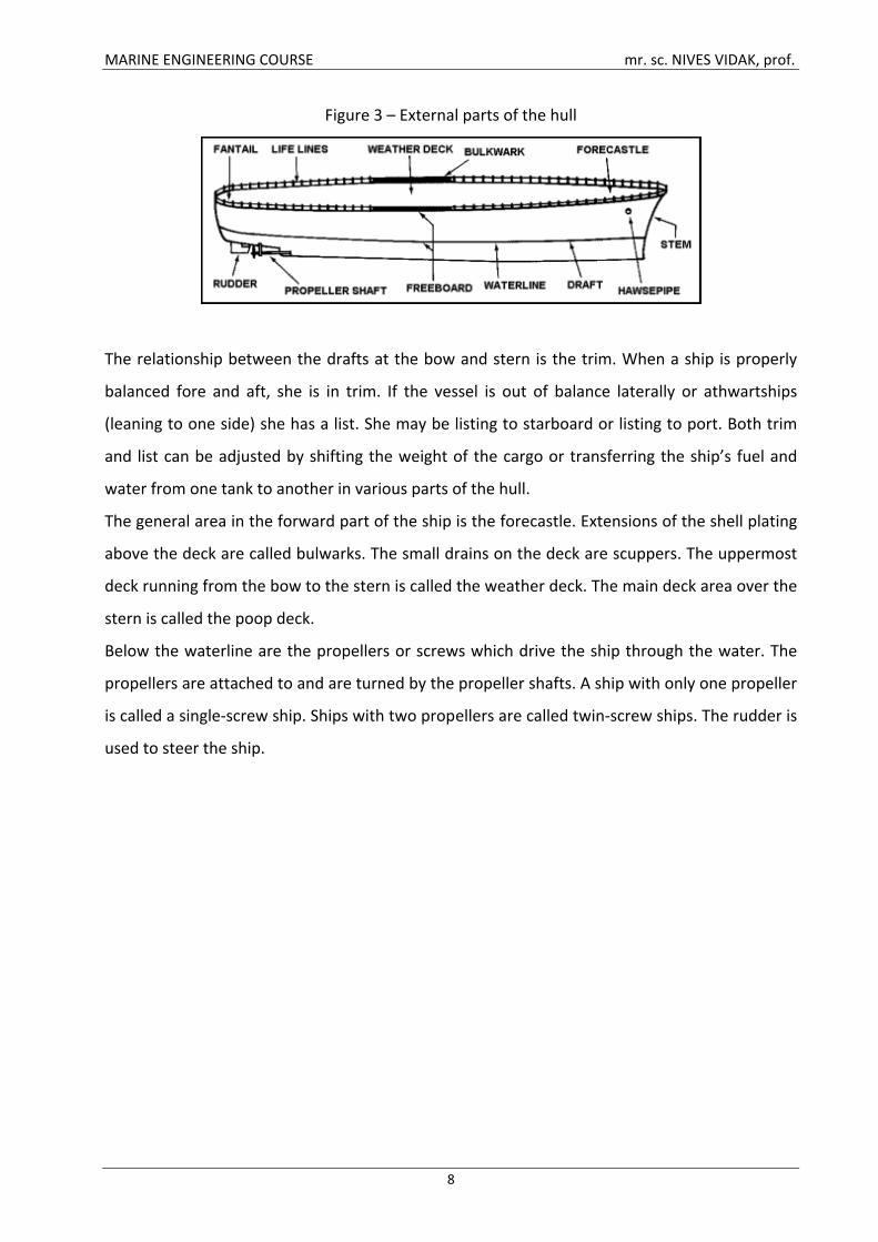
EXTERNAL PARTS OF THE HULL
The waterline is the water-level line on the hull when afloat. The vertical distance from the
waterline to the edge of the lowest outside deck is called the freeboard. The vertical distance
from the waterline to the bottom of the keel is called the draft. The waterline, draft, and
freeboard will change with the weight of the cargo and provisions carried by the ship. The draft
of the ship is measured in feet and inches. Numbered scales are painted on the side of the ship
at the bow and stern.
MARINE ENGINEERING COURSE mr. sc. NIVES VIDAK, prof.
8
Figure 3 – External parts of the hull
The relationship between the drafts at the bow and stern is the trim. When a ship is properly
balanced fore and aft, she is in trim. If the vessel is out of balance laterally or athwartships
(leaning to one side) she has a list. She may be listing to starboard or listing to port. Both trim
and list can be adjusted by shifting the weight of the cargo or transferring the ship’s fuel and
water from one tank to another in various parts of the hull.
The general area in the forward part of the ship is the forecastle. Extensions of the shell plating
above the deck are called bulwarks. The small drains on the deck are scuppers. The uppermost
deck running from the bow to the stern is called the weather deck. The main deck area over the
stern is called the poop deck.
Below the waterline are the propellers or screws which drive the ship through the water. The
propellers are attached to and are turned by the propeller shafts. A ship with only one propeller
is called a single-screw ship. Ships with two propellers are called twin-screw ships. The rudder is
used to steer the ship.
MARINE ENGINEERING COURSE mr. sc. NIVES VIDAK, prof.
9
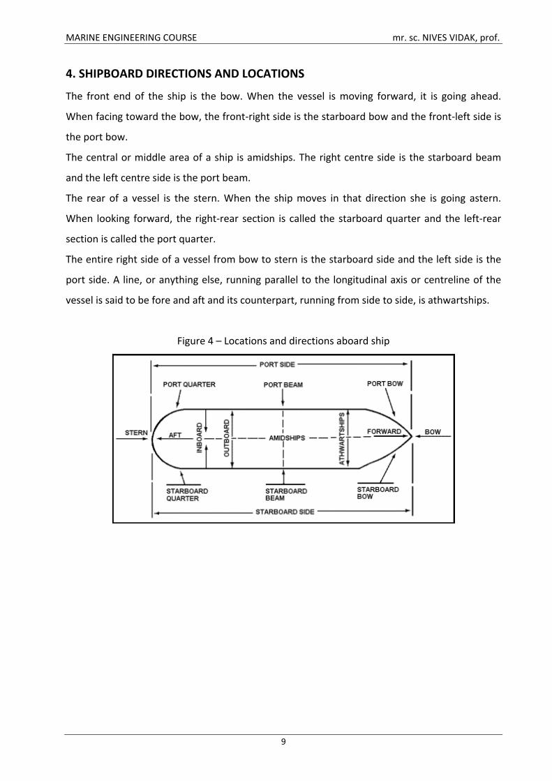
4. SHIPBOARD DIRECTIONS AND LOCATIONS
The front end of the ship is the bow. When the vessel is moving forward, it is going ahead.
When facing toward the bow, the front-right side is the starboard bow and the front-left side is
the port bow.
The central or middle area of a ship is amidships. The right centre side is the starboard beam
and the left centre side is the port beam.
The rear of a vessel is the stern. When the ship moves in that direction she is going astern.
When looking forward, the right-rear section is called the starboard quarter and the left-rear
section is called the port quarter.
The entire right side of a vessel from bow to stern is the starboard side and the left side is the
port side. A line, or anything else, running parallel to the longitudinal axis or centreline of the
vessel is said to be fore and aft and its counterpart, running from side to side, is athwartships.
Figure 4 – Locations and directions aboard ship
MARINE ENGINEERING COURSE mr. sc. NIVES VIDAK, prof.
10
5. THE ORGANISATION OF A SHIP’S CREW
The man in charge of a ship is the Master. He is responsible for the ship, her cargo and the
safety of the crew. He must be well qualified and an experienced navigator. Although his correct
title is the Master, he is addressed as ‘Captain’.
The organisation of the crew of a cargo ship is changing, but it is still customary to find Deck,
Engine and Catering Departments in ships of a reasonable size. Each department is made up of
a varied number of officers, petty officers and ratings.
The Chief Officer, or First Mate as he is often called, is the Master’s chief officer and head of the
Deck Department. He is assisted by a Second Officer (Mate), a Third Officer (Mate), and
sometimes a Fourth Officer (Mate). Several companies employ a First Officer as well as a Chief
Officer. The Deck Department also includes a Boatswain (Bosun) and a Carpenter, both petty
officers, and a number of ratings. These are made up of Able Seamen (AB), Ordinary Seamen
(OS) and a middle grade known as Efficient Deck Hands (EDH). There are other grades of
seamen. On some ships Navigating Cadets are carried for training purposes.
The Chief Engineer is head of the Engine Department. He is assisted by a Second, Third, Fourth
and sometimes Fifth Engineer. An Electrical Officer may also be carried. The engine room petty
officers are the Storekeeper and Donkeyman. On tankers there is also a Pump man. He is also a
petty officer. There may also be Engineer Cadets.
The Catering Department is under the Chief Steward. It is divided into a saloon and galley
section. The former is headed by the Second Steward, the latter by the Ship’s Cook. They are
both usually petty officers. They are assisted by several stewards and cooks, and by a number of
junior ratings.
5.1 THE DECK DEPARTMENT:
They are responsible for navigation of the ship, loading/discharge of cargo, radio
communication and control/safety of the crew, and passengers. The Master is in overall
command of the ship and is responsible for the safety, efficiency and commercial feasibility of
his ship. His duties are navigational at sea. While in ports he is responsible for cargo operations.
Master/ Captain carries out the following tasks:
o Manages navigation of the ship
o Maintains orderliness and discipline
o Ensures safety of passengers, crew and the cargo
MARINE ENGINEERING COURSE mr. sc. NIVES VIDAK, prof.
11
o Commands manoeuvring to avoid hazards
o Checks the location of the ship’s position using navigational aids
o Acts as the representative of the ship’s owner
o Assigns organisational duties for ship’s operation, navigation and maintenance with the
Chief Officer
The Chief Officer:
o Is second in command, on the ship
o Is the head of the Deck Department
o Is in charge of all maintenance, cargo loading and discharging
o Assists in navigation and discipline
The Second Officer:
o Takes charges of mails
o Maintenance of all equipment and charts used for navigation
o Cargo supervision in ports
The Third Officer:
o Undertakes responsibility for maintenance of life-boats and fire-fighting equipment
o Cargo supervision in ports
o Acts as a signal officer in charge of all signalling equipment
o Is in charge of the navigation bridge by rotation
Deck ratings are responsible for cleaning, sweeping, chipping of rust, polishing, etc. They help in
loading and unloading of cargo and in port they assist in the mooring of the ship.
5.2 THE ENGINE DEPARTMENT:
The Chief Engineer is directly responsible to the Master for the satisfactory operation of all
machinery and equipment. Apart from assuming all responsibility his role is mainly that of
consultant and adviser. It is not usual for the Chief Engineer to keep a watch.
The Second Engineer is responsible for the practical upkeep of machinery and the manning of
the engine room: he is in effect an executive officer. On some ships the Second Engineer may
keep a watch.
The Third and Fourth Engineers are usually senior watch-keepers or engineers in charge of a
watch. Each may have particular areas of responsibility, such as generators or boilers.
MARINE ENGINEERING COURSE mr. sc. NIVES VIDAK, prof.
12
Fifth and Sixth Engineers may be referred to as such, or all below Fourth Engineer may be
classed as Junior Engineers. They will make up as additional watch-keepers, day workers on
maintenance work or possibly act as Refrigeration Engineer.
Electrical Engineers may be carried on large ships or where company practice dictates. Where
no specialist Electrical Engineer is carried the duty will fall on one of the engineers.
Various engine room ratings will usually form part of the engine room complement.
Donkeymen are usually senior ratings who attend the auxiliary boiler while the ship is in port.
Otherwise they will direct the ratings in the maintenance and upkeep of the machinery space.
Engine room ratings are responsible for the day to day cleanliness of the engine room and for
the routine oiling, greasing and servicing of machinery.
MARINE ENGINEERING COURSE mr. sc. NIVES VIDAK, prof.
13
6. UMS OPERATION
The machinery spaces will usually be manned at least eight hours per day. During this time the
engineers will be undertaking various maintenance tasks, the duty engineer having particular
responsibility for the watch-keeping duties and dealing with any alarms which may occur. When
operating unmanned anyone entering the machinery space must inform the deck officer on
watch. When working or making a tour of inspection alone, the deck officer on watch should be
telephoned at agreed intervals of perhaps 15 or 30 minutes. Where the machinery space is
unattended, a duty engineer will be responsible for supervision. He will normally be one of
three senior watch-keeping engineers and will work on a 24 hour on, 48 hours off rota. During
his rota period he will make tours of inspection about every four hours beginning at 7 or 8
o'clock in the morning. The tour of inspection will be similar to that for a conventional watch
with due consideration being given to the unattended mode of machinery operation. Trends in
parameter readings must be observed, and any instability in operating conditions must be
rectified, etc. A mini-log of readings may have to be taken during the various tours. Between
tours of inspection the duty engineer will be on call and should be ready to investigate any
alarms relayed to his cabin or the various public rooms. The duty engineer should not be out of
range of these alarms without appointing a relief and informing the bridge. The main log book
readings will be taken as required while on a tour of inspection. The various regular duties, such
as fuel transfer, pumping of bilges, and so on, should be carried out during the daywork period,
but it remains the responsibility of the duty engineer to ensure that they are done.
MARINE ENGINEERING COURSE mr. sc. NIVES VIDAK, prof.
14
7. PERIODIC SAFETY ROUTINES
In addition to watch-keeping and maintenance duties, various safety and emergency equipment
must be periodically checked. As an example, the following inspections should take place at
least weekly:
1. Emergency generator should be started and run for a reasonable period. Fuel oil,
lubricating oil and cooling water supplies and tank levels should be checked.
2. Emergency fire pump should be run and the deck fire main operated for a reasonable
period. AH (audible low suction pressure alarm) operating parameters should be checked.
3. Carbon dioxide cylinder storage room should be visually examined.
4. One smoke detector in each circuit should be tested to ensure operation and correct
indication on the alarm panel. Aerosol test sprays are available to safely check some types of
detector.
5. Fire pushbutton alarms should be tested, by operating a different one during each test.
6. Any machinery space ventilators or skylights should be operated and greased, if
necessary, to ensure smooth, rapid closing should this be necessary.
7. Fire extinguishers should be observed in their correct location and checked to ensure
they are operable.
8. Fire hoses and nozzles should likewise be observed in their correct places. The nozzles
should be tried on the hose coupling. Any defective hose should be replaced.
9. Any emergency batteries, e.g. for lighting or emergency generator starting, should be
examined, and be topped up, as required.
10. All lifeboat engines should be run for a reasonable period. Fuel oil and lubricating oil
levels should be checked.
11. All valves and equipment operated from the fire control point should be checked for
operation, where this is possible.
12. Any watertight doors should be opened and closed by hand and power. The guides
should be checked to ensure that they are clear and unobstructed.
MARINE ENGINEERING COURSE mr. sc. NIVES VIDAK, prof.
15
8. SHIP’S EQUIPMENT
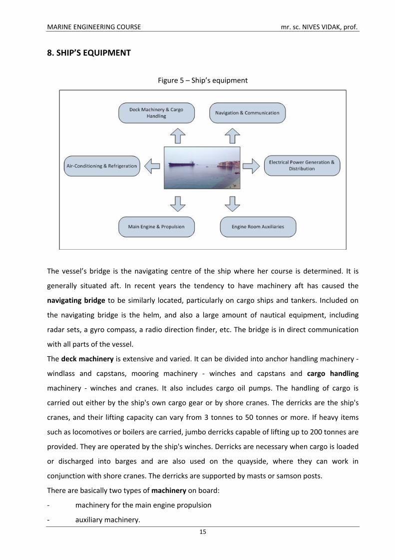
Figure 5 – Ship’s equipment
The vessel’s bridge is the navigating centre of the ship where her course is determined. It is
generally situated aft. In recent years the tendency to have machinery aft has caused the
navigating bridge to be similarly located, particularly on cargo ships and tankers. Included on
the navigating bridge is the helm, and also a large amount of nautical equipment, including
radar sets, a gyro compass, a radio direction finder, etc. The bridge is in direct communication
with all parts of the vessel.
The deck machinery is extensive and varied. It can be divided into anchor handling machinery -
windlass and capstans, mooring machinery - winches and capstans and cargo handling
machinery - winches and cranes. It also includes cargo oil pumps. The handling of cargo is
carried out either by the ship's own cargo gear or by shore cranes. The derricks are the ship's
cranes, and their lifting capacity can vary from 3 tonnes to 50 tonnes or more. If heavy items
such as locomotives or boilers are carried, jumbo derricks capable of lifting up to 200 tonnes are
provided. They are operated by the ship's winches. Derricks are necessary when cargo is loaded
or discharged into barges and are also used on the quayside, where they can work in
conjunction with shore cranes. The derricks are supported by masts or samson posts.
There are basically two types of machinery on board:
- machinery for the main engine propulsion
- auxiliary machinery.
MARINE ENGINEERING COURSE mr. sc. NIVES VIDAK, prof.
16
8.1 AUXILIARY MACHINERY
The auxiliary machinery is used to serve the main engine and the necessities of the ship. It
consists of a large group. It includes pumps, purifiers, electrical generators, fresh water
generators, heaters, coolers, oily water separator, auxiliary steam boilers, steering gears, air
conditioning machines, refrigerator machines, cargo winches, cranes, air compressors, air tanks,
oil tanks, water tanks, shafts, bow thrusters, stabilisers, fire-fighting installations, life-boat
engines, filters, and many others. This is the equipment which supports the systems of the main
engines. Some are run independently. Each auxiliary has its role to play:
• To apply the main power of the engines for propulsion and manoeuvring. The engine
power is transmitted to the propeller by a line of steel shafting. This is made up of the thrust
shaft, intermediate shafts and the propeller shaft. Steering gear is also necessary to operate the
rudder for manoeuvring.
• Steam or diesel power generators supply the ship with electric power and lighting.
• The auxiliary equipment serving to supply domestic needs e.g. fresh water from
distillation plant, sanitation from sewage plant and heating & ventilation from heaters and air
conditioners.
• Oil purifiers are used for conditioning of the bunker oil, or lubricating oil.
• Coolers are used for cooling either oil or water.
• Air compressors supply compressed air for starting engines.
• Water for the boilers is heated before being admitted into the boiler by feed water
heaters. This increases the efficiency of the boiler.
• Auxiliary boiler is used to heat up fuel oil. This is essential especially during the winter
months, when fuel oil can become very viscous.
• Fire-fighting and fire detection equipment, life-boat engines and launching gear provide
for safety.
• The bilge and ballast piping systems are installed to keep the ship dry and trimmed. The
former removes water which has gathered in machinery, cargo and other spaces. The latter
pumps water into and out of ballast tanks. In general cargo ships, these systems are usually
interconnected and served by the same pumps. In tankers and other bulk carriers, these
systems are entirely separate, because these ships may need to ballast at 12,000 tonnes/hour
and therefore need larger pumps.
MARINE ENGINEERING COURSE mr. sc. NIVES VIDAK, prof.
17
8.2 MAIN ENGINES
There are four main types of marine engine: the diesel engine, the steam turbine, the gas
turbine and the marine nuclear plant. Each type of engine has its own particular application.
8.2.1 DIESEL ENGINE
The diesel engine is a ship's reciprocating machine, the internal combustion engine. To
understand how a diesel engine works imagine the piston just near the top of its upstroke. All
access from the outer air is closed but a given volume of air has been drawn in and trapped in
between the bottom of the cylinder top and the top of the piston. Air is compressed and it
heats. At the point of maximum compression a needle valve in the cylinder head opens, a spray
of fuel enters. An explosion takes place and the piston is driven down the cylinder. Working via
the piston rod, crosshead and connecting rod, it rotates the crankshaft. No diesel engine is a
single cylinder engine, there may be as many as twelve driving one crankshaft, but each cylinder
is self-sufficient in operation.
The diesel engine is started by means of compressed air admitted into the cylinder at high
pressure via a special starting valve. There are two main types of diesel engines: one is the two-
cycle and the other is the four-cycle. The power output of a modern marine diesel engine is
about 40,000 brake horse power (bhp). This is now expressed in kilowatts. Large diesel engines,
which have cylinders near 3 ft in diameter, turn at the relatively small speed of about 108 r.p.m.
These are known as slow-speed diesel engines. They can be connected directly to the propeller
without gearing. Although higher power could be produced by higher revolutions, this would
reduce the efficiency of the propeller, because a propeller is more efficient the larger it is and
the slower it turns. These large slow-running engines are used in the larger merchant ships,
particularly in tankers and bulk carriers. The main reason is their low-fuel consumption.
More and more of the larger merchant vessels are being powered by medium-speed diesel
engines. These operate between 150 and 450 r.p.m., therefore they are connected to the
propeller by gearing. This type of engine was once restricted to smaller cargo ships, but now
they are used in fast cargo liners as well as in tankers and bulk carriers.
INTERNAL COMBUSTION ENGINE OPERATING CYCLE:
FOUR STROKE VS. TWO STROKE CYCLES
Each piston, regardless of engine type, completes two strokes for each rotation of the
crankshaft.
MARINE ENGINEERING COURSE mr. sc. NIVES VIDAK, prof.
18
A stroke is defined as either an up or down movement of the piston.
A two stroke cycle = one power stroke every shaft revolution.
Intake/Exhaust: As the piston moves towards the bottom of its stroke, air is forced into the
cylinder by a blower. At the same time, exhaust gases from the previous power stroke are
forced out of the cylinder.
Compression: As the piston moves upward, air is compressed and heated. Fuel is then injected
into the cylinder.
Combustion: Ignition occurs after fuel injection, forcing the cylinder down once again.
A four stroke cycle = one power stroke every two shaft revolutions.
Intake: The process by which air is drawn into the engine cylinders through intake valves as the
piston moves downward.
Compression: The process of reducing the area occupied by the volume of air introduced during
the intake stroke. Pressure and air temperature rise sufficiently to ignite the fuel injected into
the engine cylinders. Air is compressed and heated as the piston moves upward.
Combustion: The burning of the fuel and air in a chemical process to produce work. Fuel is
injected into the cylinder and combustion occurs causing the piston to move downward once
again.
Exhaust: The process by which the products of combustion are removed from the engine. The
piston moves upward and forces the products of combustion out of the cylinder.
CLASSIFICATION OF INTERNAL COMBUSION ENGINES:
IN-LINE: Simplest arrangements, all cylinders parallel and in a single line. Usually there are no
more than 8 cylinders due to weight and strength limitations.
V-TYPE: Piston cylinders are angled (45-75°) in a V configuration. Most V-type engines have
either 8 or 16 cylinders.
8.2.2 STEAM TURBINE
The steam turbine has until recently been the first choice for very large power main propulsion
units. Its advantages of little or no vibration, low weight, minimum space requirements and low
maintenance costs are considerable. In steam turbines high pressure steam is directed into a
series of blades or vanes attached to a shaft, causing it to rotate. This rotary motion is
transferred to the propeller shaft by gears. Steam is produced by boiling water in a boiler, which
is fired by oil. Recent developments in steam turbines which have reduced fuel consumption
MARINE ENGINEERING COURSE mr. sc. NIVES VIDAK, prof.
19
and raised power output have made them more attractive as an alternative to diesel power in
ships. They are 50% lighter and on very large tankers some of the steam can be used to drive
the large cargo oil pumps. Turbines are often used in container ships, which travel at high
speeds.
8.2.3. GAS TURBINE
Gas turbines differ from steam turbines in that gas rather than steam is used to turn a shaft.
These have also become more suitable for use in ships. Many naval vessels are powered by gas
turbines and several container ships are fitted with them. A gas turbine engine is very light and
easily removed for maintenance. It is also suitable for complete automation. The gas turbine
efficiency being low, its main advantage is its small weight and size which makes a gas turbine
installation very attractive for naval applications. Most of modern warships of about to 5,000
tonne displacement are powered with gas turbines usually combined with diesel engines. Gas
turbines are easier to start and reliable in operation. However, the use of astern gas turbines is
a rather complex problem therefore ships powered with main gas turbine units are equipped
with either controllable pitch propellers (CPP) or other reversing gears.
8.2.4. NUCLEAR PLANT
Nuclear power in ships has mainly been confined to naval vessels, particularly to submarines.
But this form of power can be used more in merchant ships as oil fuels become more expensive.
The atomic ice-breakers opened new possibilities in exploring the northern areas. They can sail
for a long time without re-fuelling. A nuclear-powered ship differs from a conventional turbine
ship in that it uses the energy released by the decay of radioactive fuel to generate steam. The
steam is used to turn a shaft via a turbine in the conventional way.
MARINE ENGINEERING COURSE mr. sc. NIVES VIDAK, prof.
20
9. STEAM TURBINE
The steam turbine has until recently been the first choice for very large power main propulsion
units. Its advantages of little or no vibration, low weight, minimal space requirements and low
maintenance costs are considerable. However, the higher specific fuel consumption when
compared with a diesel engine offsets these advantages, although refinements such as reheat
have narrowed the gap.
The steam turbine is a device for obtaining mechanical work from the energy stored in steam.
Steam enters the turbine with high energy content and leaves after giving up most of it. The
high-pressure steam from the boiler is expanded in nozzles to create a high-velocity jet of
steam. The nozzle acts to convert heat energy in the steam into kinetic energy. This jet is
directed into blades mounted on the periphery of a wheel or disc. The steam does not 'blow the
wheel around'. The shaping of the blades causes a change in direction and hence velocity of the
steam jet. Change in velocity for a given mass flow of steam will produce a force which acts to
turn the turbine wheel.
This is the operating principle of all steam turbines, although the arrangements may vary
considerably. The steam from the first set of blades then passes to another set of nozzles and
then blades and so on along the rotor shaft until it is finally exhausted. Each set comprising
nozzle and blades is called a stage.
9.1 TURBINE TYPES
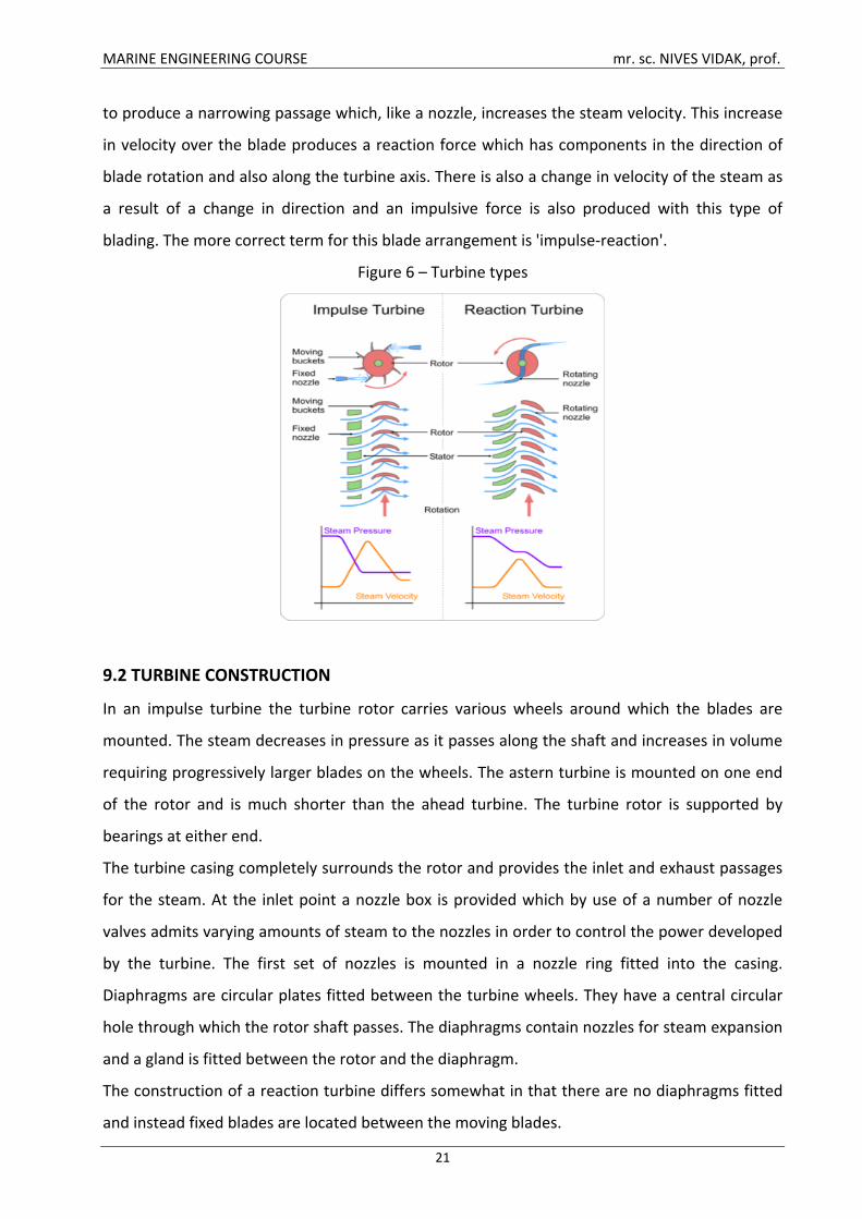
There are two main types of turbine, the 'impulse' and the 'reaction'. The names refer to the
type of force which acts on the blades to turn the turbine wheel.
Impulse
The impulse arrangement is made up of a ring of nozzles followed by a ring of blades. The high-
pressure, high-energy steam is expanded in the nozzle to a lower-pressure, high-velocity jet of
steam. This jet of steam is directed into the impulse blades and leaves in a different direction.
The changing direction and therefore velocity produces an impulsive force which mainly acts in
the direction of rotation of the turbine blades. There is only a very small end thrust on the
turbine shaft.
Reaction
The reaction arrangement is made up of a ring of fixed blades attached to the casing, and a row
of similar blades mounted on the rotor, i.e. moving blades. The blades are mounted and shaped
MARINE ENGINEERING COURSE mr. sc. NIVES VIDAK, prof.
21
to produce a narrowing passage which, like a nozzle, increases the steam velocity. This increase
in velocity over the blade produces a reaction force which has components in the direction of
blade rotation and also along the turbine axis. There is also a change in velocity of the steam as
a result of a change in direction and an impulsive force is also produced with this type of
blading. The more correct term for this blade arrangement is 'impulse-reaction'.
Figure 6 – Turbine types
9.2 TURBINE CONSTRUCTION
In an impulse turbine the turbine rotor carries various wheels around which the blades are
mounted. The steam decreases in pressure as it passes along the shaft and increases in volume
requiring progressively larger blades on the wheels. The astern turbine is mounted on one end
of the rotor and is much shorter than the ahead turbine. The turbine rotor is supported by
bearings at either end.
The turbine casing completely surrounds the rotor and provides the inlet and exhaust passages
for the steam. At the inlet point a nozzle box is provided which by use of a number of nozzle
valves admits varying amounts of steam to the nozzles in order to control the power developed
by the turbine. The first set of nozzles is mounted in a nozzle ring fitted into the casing.
Diaphragms are circular plates fitted between the turbine wheels. They have a central circular
hole through which the rotor shaft passes. The diaphragms contain nozzles for steam expansion
and a gland is fitted between the rotor and the diaphragm.
The construction of a reaction turbine differs somewhat in that there are no diaphragms fitted
and instead fixed blades are located between the moving blades.
MARINE ENGINEERING COURSE mr. sc. NIVES VIDAK, prof.
22
Lubricating oil system
Lubricating oil serves two functions in a steam turbine:
1. It provides an oil film to reduce friction between moving parts.
2. It removes heat generated in the bearings or conducted along the shaft.
A common lubrication system is used to supply oil to the turbine, gearbox and thrust bearings
and the gear sprayers. The turbine, rotating at high speed, requires a considerable time to stop.
If the main motor driven lubricating oil pumps were to fail an emergency supply of lubricating
oil would be necessary. This is usually provided from a gravity tank, although main engine
driven lubricating oil pumps may also be required.
In a lubricating oil system employing both a gravity tank and an engine driven pump the oil is
drawn from the drain tank through strainers and pumped to the coolers. Leaving the coolers,
the oil passes through another set of filters before being distributed to the gearbox, the turbine
bearings and the gearbox sprayers. Some of the oil also passes through an orifice plate and into
the gravity tank from which it continuously overflows (this can be observed through the sight-
glass). The engine driven pump supplies a proportion of the system requirements in normal
operation.
In the event of a power failure the gearbox sprayers are supplied from the engine driven pump.
The gravity tank provides a low-pressure supply to the bearings over a considerable period to
enable the turbine to be brought safely to rest.
9.3 TURBINE CONTROL
The valves which admit steam to the ahead or astern turbines are known as 'manoeuvring
valves'. There are basically three valves, the ahead, the astern and the guarding or guardian
valve. The guardian valve is an astern steam isolating valve. These valves are hydraulically
operated by an independent system employing a main and stand-by set of pumps. Provision is
also made for hand operation in the event of remote control system failure.
Operation of the ahead manoeuvring valve will admit steam to the main nozzle box. Remotely
operated valves are used to open up the remaining nozzle boxes for steam admission as
increased power is required. A speed-sensitive control device acts on the ahead manoeuvring
valve to hold the turbine speed constant at the desired value.
Operation of the astern manoeuvring valve will admit steam to the guardian valve which is
opened in conjunction with the astern valve. Steam is then admitted to the astern turbines.
MARINE ENGINEERING COURSE mr. sc. NIVES VIDAK, prof.
23
9.4 TURBINE PROTECTION
A turbine protection system is provided with all installations to prevent damage resulting from
an internal turbine fault or malfunction of some associated equipment. Arrangements are made
in the system to shut the turbine down using an emergency stop and solenoid valve. Operation
of this device cuts off the hydraulic oil supply to the manoeuvring valve and thus shuts off
steam to the turbine. This main trip relay is operated by a number of main fault conditions
which are:
1. Low lubricating oil pressure.
2. Overspeed.
3. Low condenser vacuum.
4. Emergency stop.
5. High condensate level in condenser.
6. High or low boiler water level.
Other fault conditions which must be monitored and form part of a total protection system are:
1. HP and LP rotor eccentricity or vibration.
2. HP and LP turbine differential expansion, i.e. rotor with respect to casing.
3. HP and LP thrust bearing weardown.
4. Main thrust bearing weardown.
5. Turning gear engaged (this would prevent starting of the turbine).
Such 'turbovisory' systems, as they may be called, operate in two ways. If a tendency towards a
dangerous condition is detected a first stage alarm is given. This will enable corrective action to
be taken and the turbine is not shut down. If corrective action is not rapid, is unsuccessful, or a
main fault condition quickly arises, the second stage alarm is given and the main trip relay is
operated to stop the turbine.
MARINE ENGINEERING COURSE mr. sc. NIVES VIDAK, prof.
24
10. THE MAIN TYPES OF SHIP PROPULSION SYSTEMS
The main engine of a ship is connected to its propeller with the help of a shaft. This whole
system, along with other vital machineries is known as the ship propulsion system. The type of
propulsion system used in a ship depends on several factors such as speed, power, ship type
etc.
Since the time man started using ships, various types of propulsion systems have been used
depending on the ship’s requirement. Herebelow is a brief overview of the kinds of propulsion
systems that are available in the market and their selection procedure according to the
requirement.
10.1 DIRECT DRIVE PROPULSION SYSTEM
Direct propulsion system is the most commonly used system on ships. Direct propulsion system
is an invariable choice for low-speed diesel engines and has a very basic arrangement. It
consists of a propeller, which is connected to the main engine with the help of the shaft.
Manoeuvring of the ship is done by controlling the speed of the main engine and by changing
the direction of rotation of the propeller. Initially this system was used in almost all the ships.
Direct drive propulsion system is generally used by ships plying in confined waters and in areas
wherein higher speeds are not allowed.
10.2 GEARED DRIVE PROPULSION SYSTEM
Geared drive propulsion system is extensively used nowadays. Gearing has more than one
function; it reduces the number of revolutions from the engine output in such a way that the
system can derive maximum propeller efficiency. Gearing can also be used to connect one shaft
to two prime movers or can be used to share power between two shafts or to connect a shaft
alternator to the shaft connected to the propeller.
The reversing can also be done easily by using controlled pitch propeller. However, gearing can
make the task much easier.
10.3 ELECTRICAL PROPULSION SYSTEM
Nowadays most electrical drives have medium- or high-speed diesel engines as their prime
movers. The only disadvantage of the electrical drive is that it is extremely expensive in the first
MARINE ENGINEERING COURSE mr. sc. NIVES VIDAK, prof.
25
cost when compared with geared drive. This is mainly because of lower mechanical efficiency,
which leads to more fuel consumption and cost.
In earlier times, DC motors were used with the electrical drives and the ships used to have
completely separate electrical system for propulsion and other purposes. But after the
invention of marine type thyristor converters the ships are able to connect all their machineries
to one single electrical system, just as in a power station. Thus the power for the propulsion
system, marine auxiliary machinery, and ship’s hotel load all comes from a common energy
pool. Generators are also used with the main engine to get the near peak efficiency.
Also, combining all the electrical power sources into one system has drastically helped in
reducing the extra costs and method is chosen for almost all the ships now. The system is
suitable especially for ships with high power requirements such as large cruise liners and
specialist ships such as research vessels, ice breakers, fish factory ships, oil production and
drilling vessels, cable laying ships etc. An electrical drive is thus advantageous for a ship that has
a large non propulsion electrical load or for a ship wherein the number of propulsion devices
are installed throughout the ship e.g. dynamically positioned offshore vessel.
Apart from this, advantages of electrical propulsion also include drastic reduction in noise and
vibration levels, power for the occasional use of bow thrusters without the help of any other
power source, and smooth operation at very low speeds with high level of reliability. Moreover,
an electrical propulsion system can be easily maintained and repaired. It provides the facility of
using all machineries on one fuel type. The requirement of spares is also absolutely low. The
system can work on low grade fuels, increasing the cost efficiency of the whole operation.

MARINE ENGINEERING COURSE mr. sc. NIVES VIDAK, prof.
26
11. BASIC MATHEMATICAL SYMBOLS
Table 2 – Basic mathematical symbols
Symbol Symbol Name Meaning / Definition Example
= equals sign equality 5 = 2+3
> strict inequality greater than 5 > 4
< strict inequality less than 4 < 5
( ) parentheses calculate expression inside first 2 × (3+5) = 16
[ ] brackets calculate expression inside first [(1+2) · (1+5)] = 18
+ plus sign addition 1 + 1 = 2
− minus sign subtraction 2 − 1 = 1
* asterisk multiplication 2 * 3 = 6
× times sign multiplication 2 × 3 = 6
· multiplication dot multiplication, times 2 · 3 = 6
÷ division sign division 6 ÷ 2 = 3
/ division slash division; per 6 / 2 = 3; 20 rev/s
. period decimal point, decimal separator 2.56 = 2+56/100
% percent 1% = 1/100 10% × 30 = 3
‰ per-mille 1‰ = 1/1000 = 0.1% 10‰ × 30 = 0.3
x x variable unknown value to find when 2x = 4, then x = 2
≈ approximately equal approximation sin(0.01) ≈ 0.01
∝ proportional to proportional to f(x) ∝ g(x)
∞ infinity infinity symbol ¹/o ∞ infinity
x² squared squared 3²
x³ cubed cubed 3³
x 4 fourth to the fourth; to the power four
x n nth to the n; to the nth; to the power n
√ root square root
∛ root cube root
∜ root fourth root

MARINE ENGINEERING COURSE mr. sc. NIVES VIDAK, prof.
27
Table 3 – Mathematical symbols - examples
x + 1 x plus one
x -1 x minus one
xy x y; x times y; x multiplied by y
(x — y)(x + y) x minus y, x plus y
x/y x over y; x divided by y;
x = 5 x equals 5; x is equal to 5
x ≈ y x is approximately equal to y
x ≠ y x is not equal to y
x > y x is greater than y
x < y x is less than y
x² x squared
x³ x cubed
x4 x to the fourth; x to the power four
xn x to the n; x to the nth; x to the power n
x-n x to the minus n; x to the power of minus n
√ root x; square root x; the square root of x ∛ the cube root of x ∜ the fourth root of x
the nth root of x
(x + y)² x plus y all squared
(x/y)² x over y all squared
x% x percent
∞ infinity
x ∝ y x varies as y; x is (directly) proportional to y
m/sec metres per second
MARINE ENGINEERING COURSE mr. sc. NIVES VIDAK, prof.
28
12. ENGINEERING MATERIALS
Groups of engineering materials
Based on their properties, the engineering materials can be grouped into:
1. metals
2. non-metals
Metals can be classified as ferrous and non-ferrous.
The former contain iron and the latter do not. The two most important ferrous metals are cast
iron and steel, which are both alloys, i.e. mixtures of iron and carbon. Mild steel contains from
0,15% to 0,3% of carbon. High carbon steel consists of 0,7% to 1,4% of carbon.
Aluminium, copper and the alloys (bronze and brass), zinc, tin, titanium and lead are common
non-ferrous metals.
Non-metals are plastics and ceramics.
Plastics can be classified into two types: thermoplastics (ABS, acrylic, nylon) and thermosetting
plastics (epoxy resin, polyester resin, urea formaldehyde). Thermoplastics can be shaped and
reshaped by heat and pressure, but thermosetting plastics cannot be reshaped because they
undergo chemical changes as they harden.
Ceramics are often employed by engineers when materials which can withstand high
temperatures are needed. Examples of ceramics are natural and man-made glasses used to
make bottles, windows and lenses, cements etc.
12.1 PROPERTIES OF ENGINEERING MATERIALS
Engineering materials commonly exhibit the following properties:
1. physical properties
2. mechanical properties
The physical properties of engineering materials, metals in particular, are colour, size, shape,
density, thermal and electrical conductivity, melting point, etc.
The mechanical properties exhibited by engineering materials include strength, elasticity,
plasticity, ductility, stiffness, malleability, toughness, brittleness, hardness, fatigue and creep.
Strength is the ability of a material to resist or withstand externally applied forces to which it is
subjected during a test or in service without breaking. The internal resistance by a material to
the externally applied force is called stress. Tensile strength is the main single criterion with
reference to metals.
MARINE ENGINEERING COURSE mr. sc. NIVES VIDAK, prof.
29
Elasticity is the property of a material to regain its original shape and size after deformation
when the external load or force causing the deformation is removed. A material is said to be
perfectly elastic if all the stresses (which lead to the deformation of the material) disappear
completely upon the removal of the load. This property is desirable for materials used in
machine cutting tools.
Stiffness is the ability of a material to resist deformation under stress.
Plasticity is the property of a material to remain deformed permanently or to retain a
deformation caused by an applied load permanently after the removal of the load.
Ductility is the ability of a material to withstand bending or elongation without breaking. A
material that has this characteristic is said to be ductile. This property is valuable in chains and
ropes because they don't snap off or break due to elongation and bending during service.
Malleability is the ability of a material to be hammered or rolled easily into thin sheets without
rupturing. Malleability of a material increases with the increase in temperature.
Toughness is the resistance of a material to rupture. This resistance to rupture is due to the
force of attraction between each molecule which gives them the power to resist any force
tending to tear them apart.
Brittleness is when a body breaks easily when subjected to shocks. Such a material is said to be
brittle.
Hardness is the resistance of a material to penetration. The hardness of engineering materials is
generally carried out by pressing an indentor into the surface of the material through slowly
applied load. The extent of the resulting impression caused by the indentor is then measured
mechanically and optically. A large impression means that the material is soft while a small
impression means that the material is hard.
Fatigue – When materials are subjected to fluctuating or repeating loads (or stresses), they tend
to fail. This type of failure is different from that which they experience when subjected to
steady loads. This type of failure is called FRACTURE. The phenomenon that leads to fracture is
fatigue.
Creep is the slow plastic deformation of metals under constant stress or when they are
subjected to prolonged loading at high temperature. Creep can lead to fracture at static
stresses which are much smaller than those which will break the material by loading quickly.
Creep is specially taken care of in internal combustion engines, boilers and turbines.
MARINE ENGINEERING COURSE mr. sc. NIVES VIDAK, prof.
30
13. CORROSION
A major consideration in engineering design is maintenance. One of the commonest causes of
failure in the long term is corrosion. This is any deterioration in the component’s appearance of
physical properties.
Corrosion covers a number of processes whereby a metal changes state as a result of some
form of interaction with its environment. It often occurs where water, either as a liquid or
vapour in air of high humidity, is present.
In general, corrosion becomes worse when impurities are present in damp conditions. It never
starts inside a material, and there will always be surface evidence that indicates corrosion
exists, although close examination may be needed.
Iron and steel corrode in an attempt to return to their stable oxide form. This oxidising, or
'rusting' as it is called, will take place wherever steel is exposed to oxygen and moisture.
Unfortunately the metal oxide formed permits the reaction to continue beneath it. Some
metals however produce a passive oxide film, that is, no further corrosion takes place beneath
it. Aluminium and chromium are examples of metals which form passive oxide coatings.
Corrosion control of this process usually involves a coating. This may be another metal, such as
tin or zinc, or the use of paints or plastic coatings.
Electrochemical corrosion usually involves two different metals with an electrolyte between
them. (An electrolyte is a liquid which enables current to flow through it.) A corrosion cell or
galvanic cell is said to have been set up. Current flow occurs in the cell between the two metals
since they are at different potentials. As a result of the current flow through the electrolyte,
metal is removed from the anode or positive electrode and the cathode or negative electrode is
protected from corrosion. A corrosion cell can occur between different parts of the same metal,
perhaps due to slight variations in composition, oxygen concentration, and so on. The result is
usually small holes or pits and the effect is known as 'pitting corrosion'. A more serious form of
this effect results in greater damage and is known as "crevice corrosion'. The prevention of
electrochemical corrosion is achieved by cathodic protection. Pitting and crevice corrosion can
be countered by a suitable choice of materials, certain copper alloys for instance.
'Erosion' is a term often associated with corrosion and is the wearing away of metal by
abrasion. Sea water systems are prone to problems of this nature. Increasing water velocity can
reduce pitting problems in some materials but will increase their general surface corrosion, for
example copper base alloys. Water impinging on a surface can cause erosion damage and this is

MARINE ENGINEERING COURSE mr. sc. NIVES VIDAK, prof.
31
usually found where turbulent flow conditions occur. Careful material selection is necessary to
reduce this type of erosion.
It is imperative that a design takes into account whether a material will be affected in a
particular environment and, if corrosion is likely, at what rate.
MARINE ENGINEERING COURSE mr. sc. NIVES VIDAK, prof.
32
14. MECHANISMS
Small mechanical systems can be combined to make more complex systems. Mechanisms
deliver the power to do the work. A cam which is turned by an electric motor can operate a
micro switch which could be used to turn a light on or off. Two mechanical systems can be
connected together to give complex movements.
All mechanisms involve some kind of motion. The four basic kinds of motion are:
Rotary motion is turning round in a circle, such as wheels or gears.
Linear motion is moving in a straight line, such as on a paper trimmer.
Reciprocating motion is moving backwards and forwards in a straight line, such as the
piston in a combustion engine.
Oscillating motion is swinging from side to side, like a pendulum in a clock.
Many mechanisms involve changing one kind of motion into another. For example the
reciprocating motion of a piston is changed into a rotary motion by the crankshaft, while a
camshaft converts the rotary motion of the engine into the reciprocating motion required to
operate the valves.
MARINE ENGINEERING COURSE mr. sc. NIVES VIDAK, prof.
33
15. PISTONS
Piston skirt, piston rod and trunk piston are three important parts of the piston arrangement in
marine diesel engines.
Piston Skirts
Piston skirt is fitted in both two-stroke and four-stroke engines. It has different function for
different engines. In large cross-head two-stroke engines with uniflow scavenging these skirts
are short in length and are fitted to act as a guide and to stabilize the position of the piston
inside the liner. It is generally made of cast iron. The diameter of the skirt is usually kept slightly
larger than that of the piston. This is done to prevent damage to the liner surface due to the
piston movement.
Soft bronze rings are also fitted in the piston skirts. These bronze rings help during the running-
in of the engine, when the engine is new, and can be replaced if necessary.
In two stroke engines having loop or cross scavenging arrangements the skirts are slightly larger
as these help in blanking off the scavenge and the exhaust ports in the liner.
In four-stroke or trunk piston engines the skirt has arrangement for gudgeon pin, which
transmits power from the piston to the gudgeon pin or top end bearing. As there are no cross
head guides in four-stroke engines, these skirts help in transferring the side thrust produced
from the connecting rod to the liner walls.
Piston Rods
Piston rods are generally found in large two-stroke engines. Piston rods help in transmitting the
power produced in the combustion space to the cross head and the running gear of the engine.
The lengths of these rods depend on the length of the engine stroke and the manufacturers
design. The top end of the rod is flanged or attached to the underside of the piston and the
bottom end is connected to the cross head.
The piston rod passes through the piston gland or stuffing box so the rod should have smooth
running surface and low coefficient of friction.
MARINE ENGINEERING COURSE mr. sc. NIVES VIDAK, prof.
34
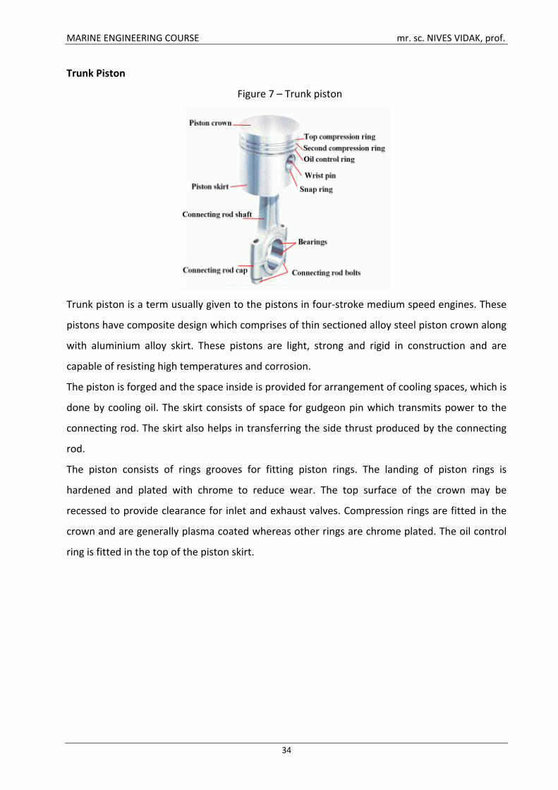
Trunk Piston
Figure 7 – Trunk piston
Trunk piston is a term usually given to the pistons in four-stroke medium speed engines. These
pistons have composite design which comprises of thin sectioned alloy steel piston crown along
with aluminium alloy skirt. These pistons are light, strong and rigid in construction and are
capable of resisting high temperatures and corrosion.
The piston is forged and the space inside is provided for arrangement of cooling spaces, which is
done by cooling oil. The skirt consists of space for gudgeon pin which transmits power to the
connecting rod. The skirt also helps in transferring the side thrust produced by the connecting
rod.
The piston consists of rings grooves for fitting piston rings. The landing of piston rings is
hardened and plated with chrome to reduce wear. The top surface of the crown may be
recessed to provide clearance for inlet and exhaust valves. Compression rings are fitted in the
crown and are generally plasma coated whereas other rings are chrome plated. The oil control
ring is fitted in the top of the piston skirt.
MARINE ENGINEERING COURSE mr. sc. NIVES VIDAK, prof.
35
16. FORCES IN ENGINEERING
The principal forces in engineering are:
Gravity. The weight, W – acts downwards. That is the gravity force. When designing and
building a vessel, weight and centre of gravity are key parameters for successful performance.
Buoyancy. The buoyancy force, B, acts upwards supporting the ship. Buoyancy depends
on weight, fluid displacement, shape and density. The weight of the displaced water equals the
upwards buoyant force.
Elasticity. The property of the material of a body by virtue of which, the body regains its
original length, volume and shape after the deforming forces have been removed, is called
elasticity. A good example is a spring. Springs exert more force the more they are stretched.
This property provides a way of measuring force. A spring balance can be calibrated in Newtons,
the unit of force.
Friction. Friction is a help in some circumstances but a hindrance in others. In order to
go faster, a ship must reduce its air and water friction as much as possible, as friction force acts
in the opposite direction than motion, i.e. slows the object down. In general, the force opposing
motion is slightly greater before one surface starts moving over another surface than after
movement has started. This slightly greater force is called static friction. The force which must
be overcome to keep one surface moving over another is known as sliding friction. Static
friction is greater than sliding friction. However, it is friction that allows the propulsion system
to 'push' the ship forward. Because friction is related to the area of contact and the vector of
the velocity, it is ideal to have the least amount of surface area facing to the direction of
motion, which is why most ships have a V-shape in the front.
MARINE ENGINEERING COURSE mr. sc. NIVES VIDAK, prof.
36
17. LUBRICATION
An engine contains many moving parts, and to prevent any wear or damage as a result of
friction, a lubricant must be applied between these parts.
Lubricating oil has many properties that have positive influences on the engine.
One of its properties is its cooling ability – the lube oil will carry away the heat that is generated
by friction between various moving parts. Furthermore, lubricating oil has the ability to prevent
impurities from clogging together. Instead, these particles will suspend and float on the surface
of the liquid. This makes it easy to remove them.
The lube oil will also serve as an anti-corrosive agent – it will prevent forming of rust. The thin
oil layer (or oil film) will seal off pits and scratches in cylinder walls.
Finally, the thickness of the lubricant will reduce engine noise considerably. This thickness of
lubricating oil is indicated by the viscosity grade. When a liquid is very ‘’viscous’’ it will resist the
tendency to flow. A liquid of low viscosity, such as water, will flow very easily through pumps
and piping systems. When the engine temperature rises, viscosity of the oil will be reduced and
the oil will become less effective. That is why it is very important to indicate the viscosity grade
of a lubricant at higher temperatures.
The lube oil is stored in the drain tank. This oil sump, as it is also called, is often integrated in
the double bottom. ‘’Ullage’’ is the space between the level of the oil and the top of the tank
and will allow for expansion of the oil when the engine gets hot. The air in this space will also
expand, and to prevent the lubricant from being forced down by the pressure that will arise
from expansion of hot air, the drain tank is fitted with an air vent. This air vent, or breather,
serves as an escape for the hot fumes that have accumulated in the drain tank.
In a forced lubricating system the lube oil is pumped from the drain tank to distribution
branches in the engine and to the shafting. Before it is entered into the engine the used oil
must first be filtered and cooled by seawater or fresh water.
MARINE ENGINEERING COURSE mr. sc. NIVES VIDAK, prof.
37
18. COOLING
Due to very high temperatures caused by combustion of the fuel and friction between various
moving parts, cooling is necessary to reduce wear and thermal deformation as a consequence
of the constant expansion and shrinking of machinery parts.
Coolants that are used in the cooling process are: seawater, fresh water, oil and air.
Seawater
The advantages of seawater as a coolant are: it is free of charge and can absorb a lot of heat.
Furthermore, a seawater cooling system can be made very simple since the used seawater can
be discharged into the sea.
The disadvantages of seawater are obvious: it contains a lot of minerals that will stick to all
heated surfaces and form a deposit. This ‘’scale’’ as it is called, must be removed, because it will
form an insulation that will prevent exchange of heat. Seawater will also cause corrosion to the
engine parts and piping. Seawater is used as a cooling medium in an indirect cooling process
(cooling the coolant). Before the coolant will be circulated through the engine again, it is cooled
with seawater by a heat exchanger. The seawater enters the ship through seawater inlets.
These inlets are fitted with sea-chests that filter the water before it is led to the heat
exchangers.
Fresh water
Freshwater has the ability to absorb much heat and will hardly cause any forming of scale.
Compared to seawater, however, fresh water is very costly. Therefore, it is only used in closed
circuits, so that it can be reused.
Oil
Oil as a coolant has a lot of advantages. Apart from cooling, it will reduce engine noise, because
the thickness of the oil will serve as a ‘’muffler’’. Oil is anti-corrosive and has a purifying
function (unwanted particles and impurities will be carried away by the oil). Another advantage
is that the oil will form a thin sealing layer that will seal off pits and scratches. Most importantly,
oil has lubricating function, which, in an engine with numerous moving parts, is a very
important aspect.

MARINE ENGINEERING COURSE mr. sc. NIVES VIDAK, prof.
38
As its disadvantage, the amount of absorbed heat per cubic metre of oil is less than that of
water. Oil may also cause carbon deposit on the surfaces that need cooling.
Air
Air has the advantage of being free of charge. However, its disadvantage is the enormous
amount of air needed to cool a small area or surface.
MARINE ENGINEERING COURSE mr. sc. NIVES VIDAK, prof.
39
19. BOILERS
A boiler in one form or another will be found on every type of ship. Where the main machinery
is steam powered, one or more large water-tube boilers will be fitted to produce steam at very
high temperatures and pressures. On a vessel propelled by a diesel engine, a smaller (usually
fire-tube type) boiler will be fitted to provide steam for the various ship services. Even within
the two basic design types, water-tube and fire-tube, a variety of designs and variations exist.
A boiler is used to heat feed water in order to produce steam. The energy released by the
burning fuel in the boiler furnace is stored (as temperature and pressure) in the steam
produced. All boilers have a furnace or combustion chamber where fuel is burnt to release its
energy. Air is supplied to the boiler furnace to enable combustion of the fuel to take place. A
large surface area between combustion chamber and water enables the energy of combustion,
in the form of heat, to be transferred to the water.
A drum must be provided where steam and water can separate. There must also be a variety of
fittings and controls to ensure that fuel oil, air and feedwater supplies are matched to the
demand for steam. Finally, there must be a number of fittings or mountings which ensure safe
operation of the boiler.
In the steam generation process feedwater enters the boiler where it is heated and becomes
steam. The feedwater circulates from the steam drum to the water drum and is heated in the
process. Large-bore downcomer tubes are used to circulate feedwater between the drums. The
downcomer tubes pass outside of the furnace and join the steam and water drums. The steam
is produced in a steam drum and may be drawn off for use from here. It is known as 'wet' or
saturated steam in this condition because it will contain small quantities of water. Alternatively,
the steam may pass to a superheater which is located within the boiler. Here steam is further
heated and 'dried', i.e. all traces of water are converted into steam. This superheated steam
then leaves the boiler for use in the system. The temperature of superheated steam will be
above that of the steam in the drum. An 'attemperator', i.e. a steam cooler, may be fitted in the
system to control the superheated steam temperature.
The hot gases produced in the furnace are used to heat the feedwater to produce steam and
also to superheat the steam from the boiler drum. The gases then pass over an economiser
through which the feedwater passes before it enters the boiler. The exhaust gases may also
pass over an air heater which warms the combustion air before it enters the furnace. In this way
MARINE ENGINEERING COURSE mr. sc. NIVES VIDAK, prof.
40
a large proportion of the heat energy from the hot gases is used before they are exhausted
from the funnel.
19.1 BOILER TYPES
Basically there are two different types of boiler:
the water-tube boiler and
the fire-tube boiler.
The design and arrangement of both the types is just the opposite. In the water-tube the
feedwater is passed through the tubes and the hot gases pass over them. In the fire-tube boiler
the hot gases pass through the tubes and the feedwater surrounds them.
The water-tube boiler is employed for high-pressure, high-temperature, high-capacity steam
applications, e.g. providing steam for main propulsion turbines or cargo pump turbines. Fire-
tube boilers are used for auxiliary purposes to provide smaller quantities of low-pressure steam
on diesel engine powered ships.
19.1.1 WATER-TUBE BOILERS
The construction of water-tube boilers, which use small-diameter tubes and have a small steam
drum, enables generation or production of steam at high temperatures and pressures. The
weight of the boiler is much smaller than an equivalent fire-tube boiler and the steam raising
process is much quicker. Design arrangements are flexible, efficiency is high and the feedwater
has a good natural circulation. These are some of the many reasons why the water-tube boiler
has replaced the fire-tube boiler as the major steam producer.
Early water-tube boilers used a single drum. Headers were connected to the drum by short,
bent pipes with straight tubes between the headers. The hot gases from the furnace passed
over the tubes, often in a single pass.
A later development was the bent tube design. This boiler has two drums, an integral furnace
and is often referred to as the 'D' type because of its shape.
19.1.2 FIRE-TUBE BOILERS
The fire-tube boiler is usually chosen for low-pressure steam production on vessels requiring
steam for auxiliary purposes. Operation is simple and feedwater of medium quality may be
employed. The name 'tank boiler' is sometimes used for fire-tube boilers because of their large
water capacity. The terms 'smoke tube' and 'donkey boiler' are also in use.
MARINE ENGINEERING COURSE mr. sc. NIVES VIDAK, prof.
41
Most fire-tube boilers are now supplied as a completely packaged unit. This will include the oil
burner, fuel pump, forced-draught fan, feed pumps and automatic controls for the system. The
boiler will be fitted with all the appropriate boiler mountings.
19.2 BOILER MOUNTINGS
Certain fittings are necessary on a boiler to ensure its safe operation. They are usually referred
to as boiler mountings. The mountings usually found on a boiler are:
Safety valves. These are mounted in pairs to protect the boiler against overpressure. Once the
valve lifting pressure is set in the presence of a surveyor it is locked and cannot be changed. The
valve is arranged to open automatically at the pre-set blow-off pressure.
Main steam stop valve. This valve is fitted in the main steam supply line and is usually of the
non-return type.
Auxiliary steam stop valve. This is a smaller valve fitted in the auxiliary steam supply line, and is
usually of the non-return type.
Feed check or control valve. A pair of valves is fitted: one is the main valve, the other the
auxiliary or standby. They are non-return valves and must give an indication of their open and
closed position.
Water level gauge. Water level gauges or 'gauge glasses' are fitted in pairs, at opposite ends of
the boiler. The construction of the level gauge depends upon the boiler pressure.
Pressure gauge connection. Where necessary on the boiler drum, superheater, etc., pressure
gauges are fitted to provide pressure readings.
Air release cock. These are fitted on the boiler drum to release air when filling the boiler or
initially raising steam.
Sampling connection. A water outlet cock and cooling arrangement is provided for the sampling
and analysis of feed water. A provision may also be made for injecting water treatment
chemicals.
Blow down valve. This valve enables water to be blown down or emptied from the boiler. It may
be used when partially or completely emptying the boiler.
Scum valve. A shallow dish positioned at the normal water level is connected to the scum valve.
This enables the blowing down or removal of scum and impurities from the water surface.
Whistle stop valve. This is a small bore non-return valve which supplies the whistle with steam
straight from the boiler drum.
MARINE ENGINEERING COURSE mr. sc. NIVES VIDAK, prof.
42
19.3 BOILER MOUNTINGS (WATER-TUBE BOILERS)
Water-tube boilers, because of their smaller water content in relation to their steam raising
capacity, require certain additional mountings:
Automatic feed water regulator. Fitted in the feed line prior to the main check valve, this device
is essential to ensure the correct water level in the boiler during all load conditions. Boilers with
high evaporation rate will use a multiple-element feed water control system.
Low level alarm. A device to provide audible warning of low water level conditions (indication).
Low low level alarm. Immediately shuts down the boiler.
Superheater circulating valves. Acting also as air vents, these fittings ensure a flow of steam
when initially warming through and raising steam in the boiler.
Sootblowers. Operated by steam or compressed air, they act to blow away soot and the
products of combustion from the tube surfaces. Several are fitted in strategic places.
MARINE ENGINEERING COURSE mr. sc. NIVES VIDAK, prof.
43
20. GENERATORS
In order to provide electric power for the lighting system, auxiliaries, cranes, derricks, hatches
and for domestic use, the ship is equipped with one or more generators. The generator is the
heart of the ship. The electrical system should be characterised in such a way that it supplies
sufficient energy to all systems of the ship and for that it is extremely essential that the correct
sizing of the generators is done. The correct sizing of the generator is the key to a safe,
workable and economic electrical system. The size of the generator depends on the load. The
load often varies or undergoes swings as the generator is connected to various other elements
such as motors, heating elements and air conditioning systems. Therefore, considerable care
should be taken that generators are susceptible to heavy system load swings.
Maritime law requires that every ship should have at least two generators. However, it is always
advisable to have three generators on board all having their individual power sources. If the
ship has three generators on board, two are used under normal working conditions and one is
kept as stand-by.
The typical marine generator burns either diesel fuel or petrol (gas). The generator produces
either alternating current (AC) or direct current (DC). A converter is used to convert AC into DC.
DC generator is a machine which produces direct current electric power. It consists of two main
parts, namely, (1) field winding and (2) armature winding. A 3 phase AC generator is called an
"alternator". Like a DC generator, it also consists of two windings. However, unlike in a DC
generator, its poles are on rotor and armature winding is on stator.
The main parts of a generator are the rotor, the stator and the commutator. The rotor is a
rotating electro-magnet. It produces a magnetic field. The rotor rotates within the stator.
Around this stator, or armature, coils of wire are wound. These coils induce electric current. The
process is called induction. The induced current is collected by the commutator. Carbon brushes
pass the current to the circuit.
Most of today's marine generators have an "electronic control module". This system keeps track
of the generator unit's performance. The electronic control module automatically adjusts the
system to maintain maximum performance level.
Maintenance of generators at regular time intervals is extremely important.
MARINE ENGINEERING COURSE mr. sc. NIVES VIDAK, prof.
44
21. SAFE WORKING PRACTICES
Accidents are usually the result of carelessness, mistakes, lack of thought or care, and often
result in injury. Consideration should be given to avoiding accidents, largely by adoption of safe
working practices.
Working clothes should be chosen with the job and its hazards in mind. They should fit fairly
closely with no loose flaps, straps or ragged pockets. Clothing should cover as much of the body
as possible and a stout pair of shoes should be worn. Neck chains, finger rings and wristwatches
should not be worn, particularly in the vicinity of rotating machinery. Where particular hazards
are present appropriate protection, such as goggles or ear muffs, should be worn.
When overhauling machinery or equipment it must be effectively isolated from all sources of
power. This may involve unplugging from an electrical circuit or removal of fuses.
Suction and discharge valves of pumps should be securely closed and the pump casing relieved
of pressure. Special care should be taken with steam-operated or steam-using equipment to
ensure no pressure build-up can occur.
Before any work is done on the main engine, the turning gear should be engaged and a warning
posted at the control position.
Lubricating oil in the working area should be cleaned up and where necessary suitable staging
erected.
The turning gear should be made inoperative if not required during the overhaul. Where it is
used, care must be taken to ensure all personnel are clear before it is used.
Where overhead work is necessary suitable staging should be provided and adequately lashed
down. Staging planks should be examined before use and where suspect discarded. Where
ladders are used for access they must be secured at either end. Personnel working on staging
should take care with tools and store them in a container.
Boiler blowbacks can cause serious injury and yet with care can usually be avoided. The furnace
floor should be free of oil and burners regularly checked to ensure that they do not drip,
particularly when not in use. The manufacturer's instructions should be followed with regard to
lighting up procedures. Generally this will involve blowing through the furnace (purging) with air
prior to lighting up. The fuel oil must be at the correct temperature and lit with a torch. If
ignition does not immediately occur the oil should be turned off and purging repeated before a
second attempt is made. The burner should be withdrawn and examined before it is lit.
MARINE ENGINEERING COURSE mr. sc. NIVES VIDAK, prof.
45
Entry into an enclosed space should only take place under certain specified conditions. An
enclosed space, such as a duct keel, a double bottom tank, a cofferdam, boiler, etc. cannot be
assumed to contain oxygen. Anyone requiring to enter such a space should only do so with the
permission of a responsible officer. The space should be well ventilated before entry takes place
and breathing apparatus taken along; it should be used if any discomfort or drowsiness is felt.
Another person should remain at the entrance to summon assistance if necessary, and there
should be a means of communication arranged between the person within the space and the
attendant. Lifelines and harness should be available at the entrance to the space. The attendant
should first raise the alarm where the occupant appears in danger but should not enter the
space unless equipped with breathing apparatus.
Training in the use of safety equipment and the conduct of rescues is essential for all personnel
involved.
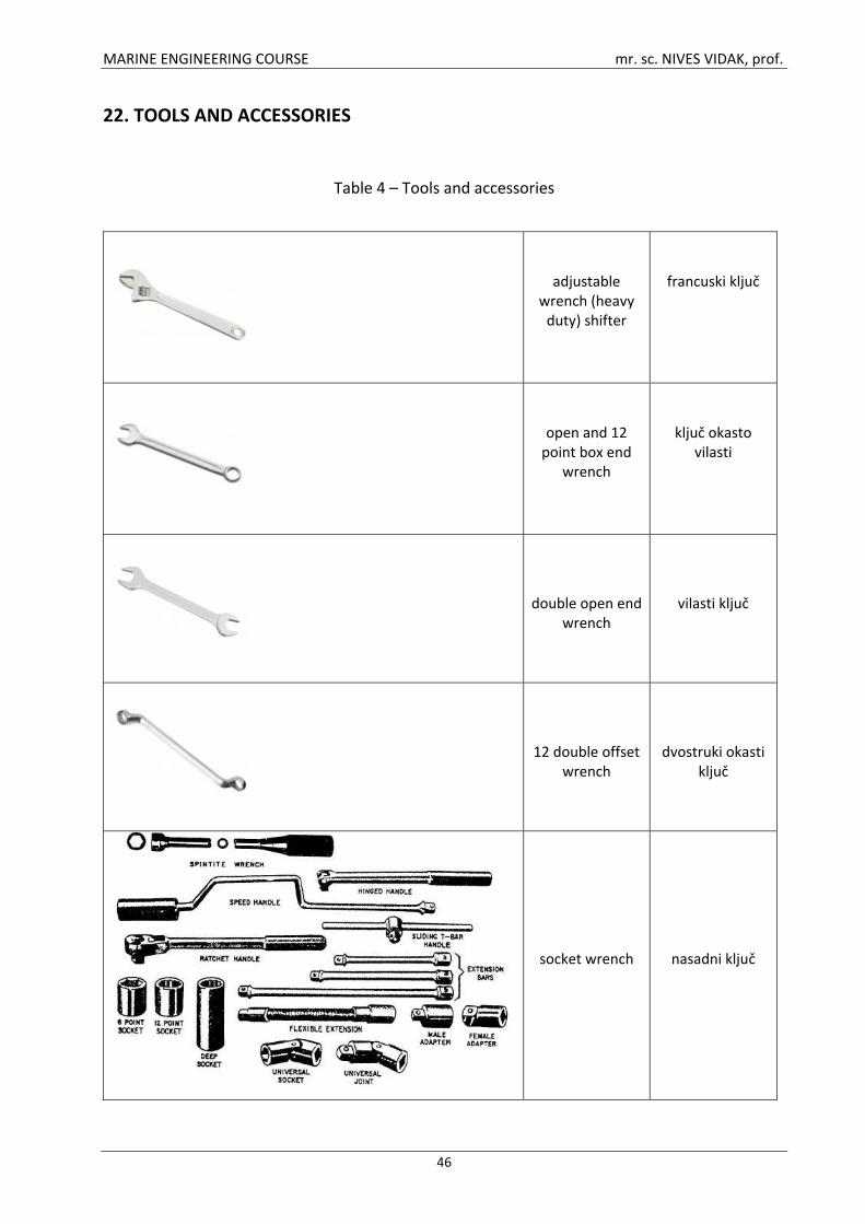
MARINE ENGINEERING COURSE mr. sc. NIVES VIDAK, prof.
46
22. TOOLS AND ACCESSORIES
Table 4 – Tools and accessories
adjustable wrench (heavy
duty) shifter
francuski ključ
open and 12 point box end
wrench
ključ okasto vilasti
double open end wrench
vilasti ključ
12 double offset wrench
dvostruki okasti ključ
socket wrench
nasadni ključ

MARINE ENGINEERING COURSE mr. sc. NIVES VIDAK, prof.
47
monkey wrench, pipe wrench
engleski ključ
general purpose screwdriver
odvijač ravni
square blade screwdriver
odvijač križni
electricians screwdriver
ispitivač
thin bent nose pliers
povijena kliješta
long nose straight pliers
špicasta kliješta
electrical cable strippers
kliješta za skidanje izolacije
water pump pliers
kliješta za cijevi, papagaj
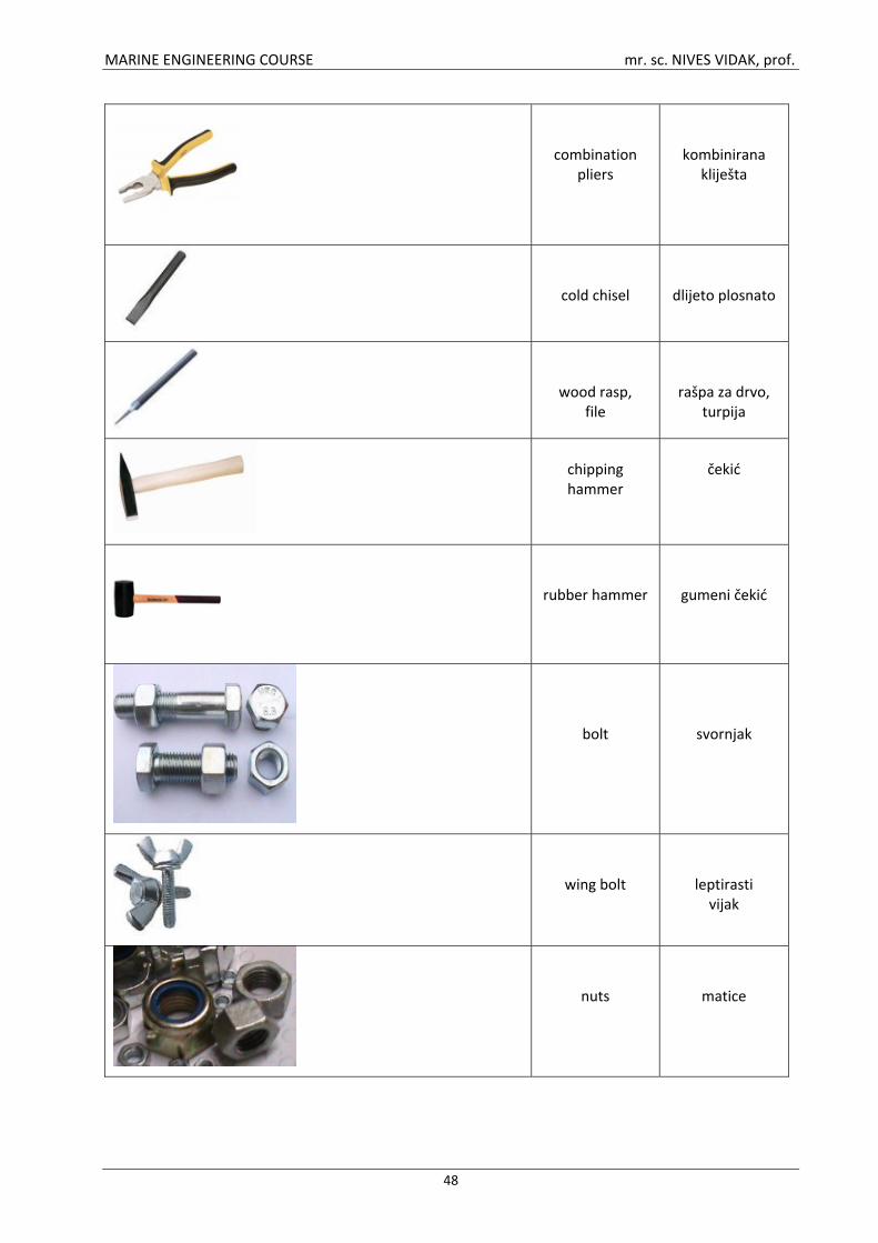
MARINE ENGINEERING COURSE mr. sc. NIVES VIDAK, prof.
48
combination pliers
kombinirana kliješta
cold chisel
dlijeto plosnato
wood rasp, file
rašpa za drvo, turpija
chipping hammer
čekić
rubber hammer
gumeni čekić
bolt
svornjak
wing bolt
leptirasti vijak
nuts
matice
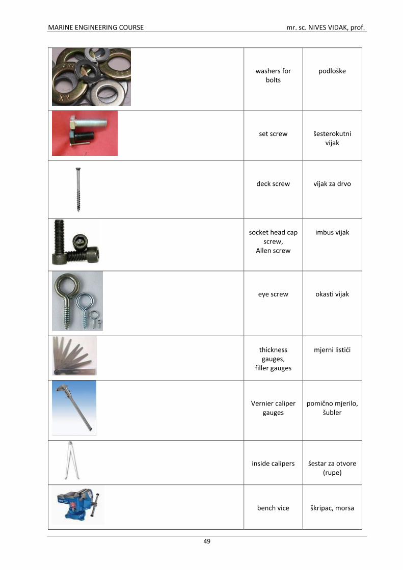
MARINE ENGINEERING COURSE mr. sc. NIVES VIDAK, prof.
49
washers for bolts
podloške
set screw
šesterokutni vijak
deck screw
vijak za drvo
socket head cap
screw, Allen screw
imbus vijak
eye screw
okasti vijak
thickness gauges,
filler gauges
mjerni listići
Vernier caliper gauges
pomično mjerilo, šubler
inside calipers
šestar za otvore (rupe)
bench vice
škripac, morsa
MARINE ENGINEERING COURSE mr. sc. NIVES VIDAK, prof.
50
23. REFERENCES
1. Glendinning, E. H., Glendinning, N. 2000: Oxford English for Electrical and Mechanical
Engineering, Oxford University Press
2. Spinčić, A. 1987: English Textbook for Marine Engineers, FPS Rijeka
3. MAN B&W DIESEL A/S, Engineers Training Course
4. Christensen, S.G.1990: Questions and Answers on the Marine Diesel Engine, Edward Arnold
Great Britain
5. Taylor, D. A. 2003: Introduction to Marine Engineering Course, http://ebookee.org/
Introduction -to -Marine -Engineering -Second-Edition_316660.html
6. Marine Insight, http://marineinsight.com/
7. Marine Engineering Online Resource, http://www.marineengineeringonline.com/index.htm

MARINE ENGINEERING COURSE mr. sc. NIVES VIDAK, prof.
51
24. LIST OF TABLES AND FIGURES
Table 1 – Types of merchant ships ........................................................................................ 4
Table 2 – Basic mathematical symbols ................................................................................ 26
Table 3 – Mathematical symbols – examples ..................................................................... 27
Table 4 – Tools and accessories .......................................................................................... 46
Figure 1 – Construction of a hull ........................................................................................... 6
Figure 2 – Bulkheads and decks ............................................................................................ 7
Figure 3 – External parts of the hull ...................................................................................... 8
Figure 4 – Locations and directions aboard ship .................................................................. 9
Figure 5 – Ship’s equipment ................................................................................................ 15
Figure 6 – Turbine types ...................................................................................................... 21
Figure 7 – Trunk piston ........................................................................................................ 34