Embed Size (px)
Citation preview
made in europe
advanced qualitycustomized designs
Ihr Partner für Kühler und Systeme
� Kompaktes Design
� Variable Einbaulagen
� Äusserst Leistungsfähig
� Geringe Kosten
� Compact design
� Variable mounting positions
� Very high-performancedevice
� Low costs
� Construction compacte
� Situations de montage variables
� Extrêmement performant
� Coûts réduits
Nebenstrom-KühlaggregatPartial-flow Cooling UnitRefroidisseur à dérivation
Serie
TFS/AFür den industriellen Einsatz
For industrial application
A usage industriel
Ihr Partner für Kühler und Systeme
Produktbeschreibung
Der TFS/A ist ein kompaktes Nebenstrom-kühlaggregat. Es wurde entwickelt um dieVerfügbarkeit und die Zuverlässigkeit vonhydraulischen Anlagen zu verbessern.Durch die Verbindung aus Motor-Pumpen-station und Öl-Luftkühler in einem Gerätstellt der TFS/A eine eigenständige Einheitdar, die unabhängig von dem eigentlichenAggregat betrieben werden kann. Dadurchkann eine kontinuierliche Kühlung gewähr-leistet werden.
Produktmerkmale
� Kompakte Bauweise� Geräuscharmer Betrieb� Wartungsfreundlich, da die Anzahl der
Verschleißteile konsequent reduziert wurde
� Standardmäßig mit Mehrbereichs-motoren ausgestattet
� Beliebige Einbaulagen möglich� Option: Thermobypassventil,
Thermostat
Vorteile� Verlängerung der Standzeiten der
Hydraulikkomponenten� Erhöhung der Einsatzzuverlässigkeit� Verbesserung der Positionier -
ge nauigkeit� Problemlose Nachrüstung an
bestehenden Anlagen möglich
Product description
The TFS/A is a compact partial-flow coolingunit. It was developed to improve the avai-lability and reliability of hydraulic systems.Due to its combination of a motorpump unitand an oil-air cooler in one device, theTFS/A is an autonomous unit, which can beoperated independently of the mainsystem. In this manner continuous coolingis ensured.
Product features
� Compact design� Nearly noiseless operation� Ease of maintenance, since the
number of working parts has been consequently reduced
� Equipped with multirange motors as standard equipment
� Any arbitrary mounting position is possible
� Option: Thermo bypass valve,Thermostat
Advantages� Extension of the service life of the
hydraulic components� Enhancement of the application
reliability� Improvement of the positioning
accuracy� Unproblematical retrofitting on
existing systems is possible
Description du produit
Le TFS/A est un refroidisseur compact àdérivation. Il a été développé pour amélio-rer la disponibilité et la fiabilité d’installati-ons hydrauliques. Alliant dans un appareilune station de pompage moteur à un re -froi disseur huile/air, le TFS/A est une unitéautonome pouvant être utilisée indépen-damment de l’agrégat proprement dit.Ceci permet d’assurer un refroidissementpermanent.
Caractéristiques du produit
� Construction compacte� Nuisance acoustique réduite� Maintenance facile, le nombre des
pièces à usure ayant été réduit de manière systématique
� Equipé de manière standard de moteurs multigrades
� Situations de montage quelconques possibles
� Option: Soupape bypass thermique,Thermostat
Avantages� Prolongement de la longévité des
composantes hydrauliques� Augmentation de la fiabilité à
l’utilisation� Amélioration de l’exactitude de
positionnement� Equipement ultérieur sans problème
sur des installations existantes
Produktbeschreibung / Product description / Description du produit
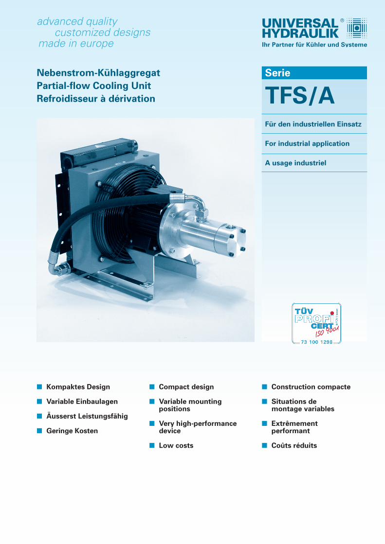
Kühlleistung / Cooling capacity / Puissance frigorifique
TFS/A - 13
TFS/A - 8,5
Kü
hlle
istu
ng
kW
/ C
oo
ling
per
form
ance
kW
/
Pu
issa
nce
de
refr
oid
isse
men
t kW
Eintrittstemperaturdifferenz ETD [K] / Inlet Temperature difference oil to air / Différence de temperature entrée entre huile et air
TFS/A - 20
TFS/A - 32
02468101214161820222426283032343638404244464850
0 5 10 15 20 25 30 35 40 45
Kühlleistung TFS/A-BaureiheModell / Model / Modèle
ETD Standard
DTE Pumpe / Pump / Pompe
(kW Δt 40°C) (l/min)
TFS / A - 8,5 8,5 30
TFS / A - 13 13 38
TFS / A - 20 20 50
TFS / A - 32 32 80
Kühlleistung des Öl-Luftkühlers (mit Förderpumpe) in Abhängig-keit von der Eintritts-Temperatur-Differenz Öl zu Luft.
Cooling capacity of the oil-air cooler (with feed pump) as afunction of the input temperature difference of oil to air.
Puissance frigorifique du refroidisseur huile/air (avec pomped’acheminèment) en fonction de la différence de températured’entrée huile-air.
Ihr Partner für Kühler und Systeme
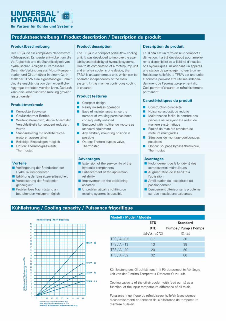
Geräteabmessungen / Unit dimensions / Dimensions des appareils
Eÿ G30
D
Öleingang
Ölausgang
A B
C
I
HF
C
A Bÿ I
ÿ H
ED
ÿ G
Ölausgang
Öleingang
TFS / A - ... F
TFS / A - ... WH / DH
... - 8,5
195
150
622
340
240
430
11
G 1“
G 1“
... - 13
256
150
682
480
380
549
11
G 1“
G 1“
... - 20
237
150
766
480
380
549
11
G 1“
G 1“
... - 32
127
370
764
654
554
722
12
G 11/2“
G 11/2“
in mm
A
B
C
D
E
F
G
H
I
... - 8,5
61
200
779
342
298
573
26 x 13
G 1“
G 1“
... - 13
70
263
865
480
440
714
11 x 21
G 1 “
G 1“
... - 20
70
263
949
480
440
714
11 x 21
G 1“
G 1“
... - 32
a.A.
a.A.
a.A.
a.A.
a.A.
a.A.
a.A.
a.A.
a.A.
in mm
A
B
C
D
E
F
G
H
I
made in europe
advanced qualitycustomized designs
Ihr Partner für Kühler und Systeme
UH-K000.030/0217
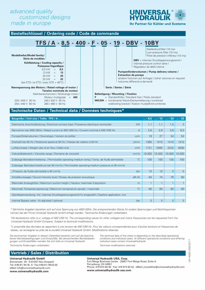
Baugröße / Unit size / Taille: TFS / A ...
Elektrische Anschlußleistung / Electrical connect load / Puissance électrique connectée kW
Nennstrom bei 400V-50Hz / Rated current at 400 V/50 Hz / Courant nominal à 400 V/50 Hz A
Pumpenfördervolumen / Devicetype / Version du boîtier ccm
Drehzahl bei 50 Hz / Rotational speed at 50 Hz / Vitesse de rotation à 50 Hz U/min
Luftdurchsatz / Weight rate of air flow / Débit d’air m3/h
Viskositätsbereich / Viscosity range / Domaine de viscosité mm2/s
Zulässige Betriebsmitteltemp. / Permissible operating medium temp./ Temp. de fluide admissible °C
Zulässiger Betriebsmitteldruck bei 40 mm2/s / Permissible operating-medium pressure at 40 mm2/s
/ Pression de fluide admissible à 40 mm2/s bar
Schalldruckpegel / Sound intensity level / Niveau de pression acoustique dB (A)
Maximale Ansaughöhe / Maximum suction height / Hauteur maximale d’aspiration m
Maximale Temperaturspreizung / Maximum temperature spread / maximale °C
Getriebeanwendung: inkl. internes Druckbegrenzungsventil fix eingestellt / Gearbox application: incl.
internal Bypass valve - fix adjusted / optional bar
* Sämtliche Angaben beziehen sich auf eine Spannung von 400V-50Hz. Die entsprechenden Werte für andere Spannungen und Netzfrequenzen können bei der Firma Universal Hydraulik GmbH erfragt werden. Technische Änderungen vorbehalten.
*All declarations refer to a voltage of 400 V/50 Hz. The corresponding values for other voltages and mains frequencies can be requested from theUniversal Hydraulik GmbH Company. Subject to technical modifications.
*L’ensemble des données se rapportent à une tension de 400 V/50 Hz. Pour les valeurs correspondantes pour d’autres tensions et fréquences deréseau, se renseigner au près de la société Universal Hydraulik GmbH. Modifications réservés.
Technische Daten / Technical data / Données techniques*
TFS / A - 8,5 - 400 - F - 05 - 19 - DBV - 10BY
Bestellschlüssel / Ordering code / Code de commande
Modellreihe/Model family/Série de modèles
Kühlleistung / Cooling capacity / Puissance frigorifique
8,5 kW = 8,513 kW = 1320 kW = 2032 kW = 32
(bei ETD / at ETD / avec DTE = 40°C)
Nennspannung des Motors / Rated voltage of motor /Tension nominale du moteur
Mehrbereichsmotor / Multirange motor / Moteur multigrade = 400
230 / 400 V 50 Hz 240 / 420 V 50 Hz254 / 440 V 60 Hz 280 / 480 V 60 Hz
Befestigung / Mounting / FixationF = Standardfüße / Standard feet / Pieds standardWH/DH = kombinierte Wand-/Deckenhalterung / combined
wall/ceiling bracket / fixation mur/plafond combinée
Serie / Series / Série
... - 8,5
1,1
2,6
19
1385
1131
10-300
100
10
64
1
60
5
... - 13
1,1
2,6
27
1410
2565
10-300
100
10
74
1
60
5
... - 20
1,5
3,6
34
1410
2232
10-300
100
5
76
1
60
5
... - 32
3
6,5
52
1410
4500
10-300
100
5
80
1
60
5
Vertrieb / Sales / DistributionUniversal Hydraulik GmbHSiemensstr. 33 . D-61267 Neu-AnspachTel: 0 60 81/ 94 18 - 0 . Fax 0 60 81/ 96 02 20eMail [email protected]
Pumpenfördervolumen / Pump delivery volume / Extraction de pompe(andere Volumen auf Anfrage) / (other volumes on request)(volumes differents à demand)
DBV = internes Druckbegrenzungsventil /internal pressure control valve / Régulateur de débit interne
Niederdruckfilter (10 my)Low pressure filter (10 my)Filtre de pression inférieur (10 my)
Die technischen Angaben in diesem Datenblatt beziehen sich auf die beschrie-benen Betriebsbedingungen und Einsatzfälle. Bei abweichenden Betriebsbedin-gungen und Einsatzfällen wenden Sie sich bitte an Universal Hydraulik.
Technische Änderungen vorbehalten.
The technical data of this sheet is depending on the described operational conditions and individual cases. At different operational conditions and differingindividual cases contact UniversalHydraulik.
Technical modifications reserved.
Universal Hydraulik USA, Corp.Fort Meigs Business Center . 25651 Fort Meigs Road, Suite APerrysburg, OH 43551Phone: 419 873 63 40 . Fax: 419 873 63 42 . eMail j.d.solether@universalhydraulik.comwww.universalhydraulik-usa.com


![Équations Différentielles Stochastiques Rétrogrades[PP92] , Backward stochastic differential equations and quasilinear parabolic partial differential equations, Stochastic partial](https://img.pdfslide.fr/doc/110x75/5f3f690470d8062e9676eb02/quations-diirentielles-stochastiques-r-pp92-backward-stochastic-diierential.jpg)