Embed Size (px)
Citation preview
Operating and Installation InstructionsDiaphragm Vacuum Pumps
and Compressors Type Ranges:
UN035ANI UN035ATI UN035AT.16I UN035AVI UN035SNI UN035SN.9I UN035STI UN035ST.9I UN035ST..11I UN035ST.16I UN035SVI UN035SV.9I UN035TNI UN035TTI UN035TVI
UN035.0ANI UN035.0AT.16I UN035.0ST.11I UN035.0ST.16I UN035.0ST.26I UN035.0SVI UN035.0TTI
UN035.1ANI UN035.1AN.9.21IUN035.1ATI UN035.1AVI UN035.1STI UN035.1SVI UN035.1TTI UN035.1TVI
UN 035.1.2ANI UN035.1.2AN.9I UN035.1.2ATI UN035.1.2AT.9I UN035.1.2AVI UN035.1.2STI UN035.1.2ST.9I UN035.1.2ST.11I UN035.1.2ST.16I UN035.1.2ST.26I UN035.1.2SVI UN035.1.2SV.9I UN035.1.2TNI UN035.1.2TTI UN035.1.2TVI
UN035.2ANI UN035.2ATI UN035.2AVI UN035.2STI UN035.2SVI UN035.2TTI
UN035.3ANI UN035.3AN.9I UN035.3ATI UN035.3AVI UN035.3STI UN035.3ST.9I UN035.3ST.11IUN035.3SVI UN035.3SV.9I UN035.3TTI UN035.3TVI
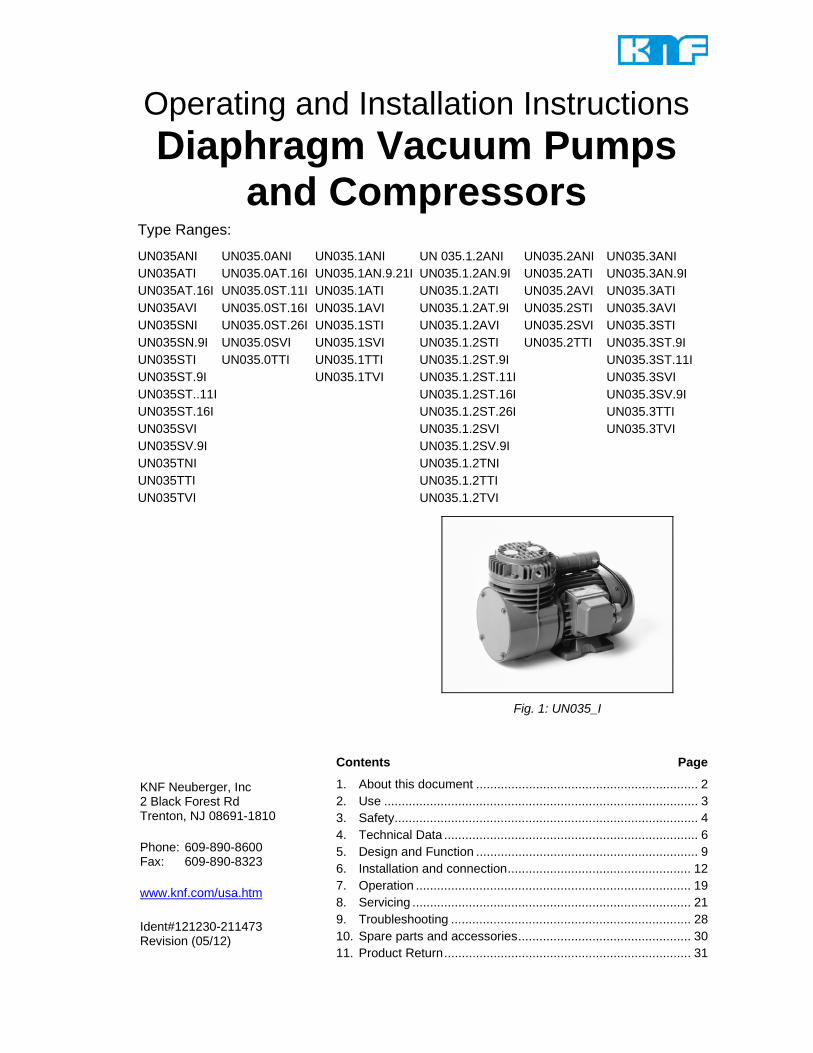
Fig. 1: UN035_I
Contents Page
1. About this document ............................................................... 2 2. Use ......................................................................................... 3 3. Safety ...................................................................................... 4 4. Technical Data ........................................................................ 6 5. Design and Function ............................................................... 9 6. Installation and connection .................................................... 12 7. Operation .............................................................................. 19 8. Servicing ............................................................................... 21 9. Troubleshooting .................................................................... 28 10. Spare parts and accessories ................................................. 30 11. Product Return ...................................................................... 31
KNF Neuberger, Inc 2 Black Forest Rd Trenton, NJ 08691-1810 Phone: 609-890-8600 Fax: 609-890-8323 www.knf.com/usa.htm Ident#121230-211473 Revision (05/12)
About this document Diaphragm Pump UN035_I
2
1. About this document 1.1. Using the Operating and Installation Instruc-
tions The operating and installation instructions are part of the pump.
Pass on the Operating and Installation Instructions to the next owner.
Customer-specific project pumps (pump models which begin with “PU” or “MPU”) may differ from the Operating and Installation Instructions.
For project pumps, also observe the agreed upon specifications.
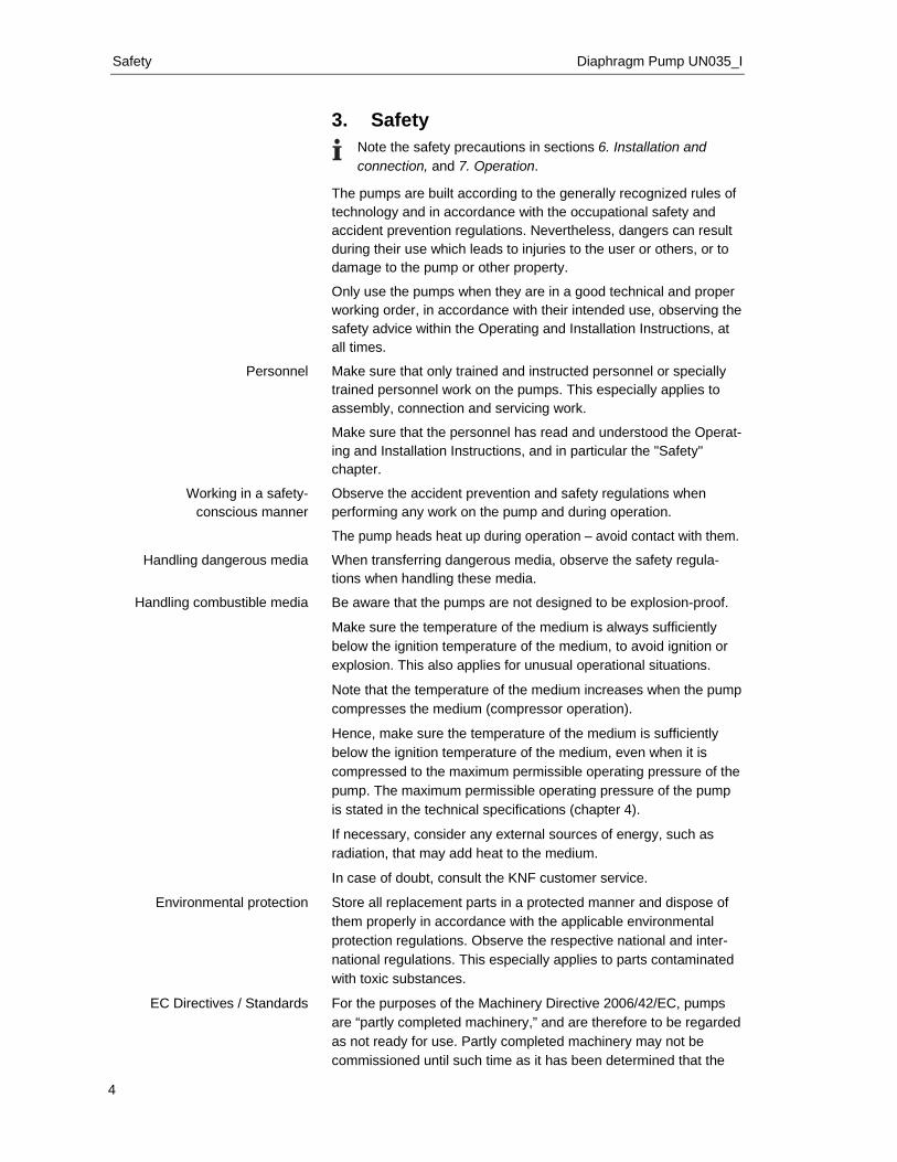
1.2. Symbols and Markings Warning
WARNING
A danger warning is located here. Possible consequences of a failure to observe the warning are specified here. The signal word, e.g. Warning, indicates the danger level.
Measures for avoiding the danger and its conse-quences are specified here.
Danger levels
Signal word Meaning Consequences if not observed DANGER warns of immedi-
ate danger Death or serious injuries and/or serious damage are the consequence.
WARNING warns of possible danger
Death or serious injuries and/or serious damage are possible.
CAUTION warns of a possibly dangerous situa-tion
Minor injuries or damage are possible.
Tab. 1 Other information and symbols
An activity to be carried out (a step) is specified here.
1. The first step of an activity to be carried out is specified here. Additional, consecutively numbered steps follow.
This symbol refers to important information.
Project pumps

Diaphragm Pumps UN035_I Use
3
2. Use 2.1. Proper use The pumps are exclusively intended for transferring gases and vapors.
Owner's responsibility
Only install and operate the pumps under the operating parameters and conditions described in Chapter 4, Technical data.
Before using a medium, check whether the medium can be trans-ferred danger-free in the specific application case.
Before using a medium, check the compatibility of the materials of the pump head, structured diaphragm and valves with the medium.
Only transfer gases which remain stable under the pressures and temperatures occurring in the pump. 2.2. Improper use The pumps may not be operated in an explosive atmosphere.
The pumps are not suitable for transferring dusts.
The pumps are not suitable for transferring liquids.
Pumps with three-phase motor are not provided for the operation with frequency converter.
Operating parameters and conditions
Requirements for transferred medium
Safety Diaphragm Pump UN035_I
4
3. Safety
Note the safety precautions in sections 6. Installation and connection, and 7. Operation.
The pumps are built according to the generally recognized rules of technology and in accordance with the occupational safety and accident prevention regulations. Nevertheless, dangers can result during their use which leads to injuries to the user or others, or to damage to the pump or other property.
Only use the pumps when they are in a good technical and proper working order, in accordance with their intended use, observing the safety advice within the Operating and Installation Instructions, at all times.
Make sure that only trained and instructed personnel or specially trained personnel work on the pumps. This especially applies to assembly, connection and servicing work.
Make sure that the personnel has read and understood the Operat-ing and Installation Instructions, and in particular the "Safety" chapter.
Observe the accident prevention and safety regulations when performing any work on the pump and during operation.
The pump heads heat up during operation – avoid contact with them.
When transferring dangerous media, observe the safety regula-tions when handling these media.
Be aware that the pumps are not designed to be explosion-proof.
Make sure the temperature of the medium is always sufficiently below the ignition temperature of the medium, to avoid ignition or explosion. This also applies for unusual operational situations.
Note that the temperature of the medium increases when the pump compresses the medium (compressor operation).
Hence, make sure the temperature of the medium is sufficiently below the ignition temperature of the medium, even when it is compressed to the maximum permissible operating pressure of the pump. The maximum permissible operating pressure of the pump is stated in the technical specifications (chapter 4).
If necessary, consider any external sources of energy, such as radiation, that may add heat to the medium.
In case of doubt, consult the KNF customer service.
Store all replacement parts in a protected manner and dispose of them properly in accordance with the applicable environmental protection regulations. Observe the respective national and inter-national regulations. This especially applies to parts contaminated with toxic substances.
For the purposes of the Machinery Directive 2006/42/EC, pumps are “partly completed machinery,” and are therefore to be regarded as not ready for use. Partly completed machinery may not be commissioned until such time as it has been determined that the
Personnel
Working in a safety- conscious manner
Handling dangerous media
Handling combustible media
Environmental protection
EC Directives / Standards
Diaphragm Pumps UN035_I Safety
5
machine in which the partly completed machinery is to be assembled is in conformity with the provisions of the Machinery Directive 2006/42/EC. The essential requirements of Annex I of Directive 2006/42/EC (general principles) are applied and observed.
The pumps conform to the EC Directive 2004/108/EC concerning Electromagnetic Compatibility.
The following harmonized standards have been used:
IP20 IP44 EN 55014-1/2 EN 55014-1/2 EN 61000-3-2/3 EN 61000-3-2/3 EN 60335-1 EN 60204-1
Tab. 2
Only have repairs to the pump carried out by the KNF Customer Service responsible.
Use only genuine parts from KNF for servicing work.
Customer service and repairs
Technical Data Diaphragm Pump UN035_I
6
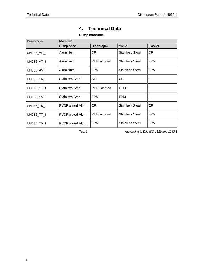
4. Technical Data Pump materials
Pump type Material* Pump head Diaphragm Valve Gasket
UN035_AN_I Aluminium CR Stainless Steel CR
UN035_AT_I Aluminium PTFE-coated Stainless Steel FPM
UN035_AV_I Aluminium FPM Stainless Steel FPM
UN035_SN_I Stainless Steel CR CR -
UN035_ST_I Stainless Steel PTFE-coated PTFE -
UN035_SV_I Stainless Steel FPM FPM -
UN035_TN_I PVDF plated Alum. CR Stainless Steel CR
UN035_TT_I PVDF plated Alum. PTFE-coated Stainless Steel FPM
UN035_TV_I PVDF plated Alum. FPM Stainless Steel FPM Tab. 3 *according to DIN ISO 1629 und 1043.1
Diaphragm Pumps UN035_I Technical Data
7
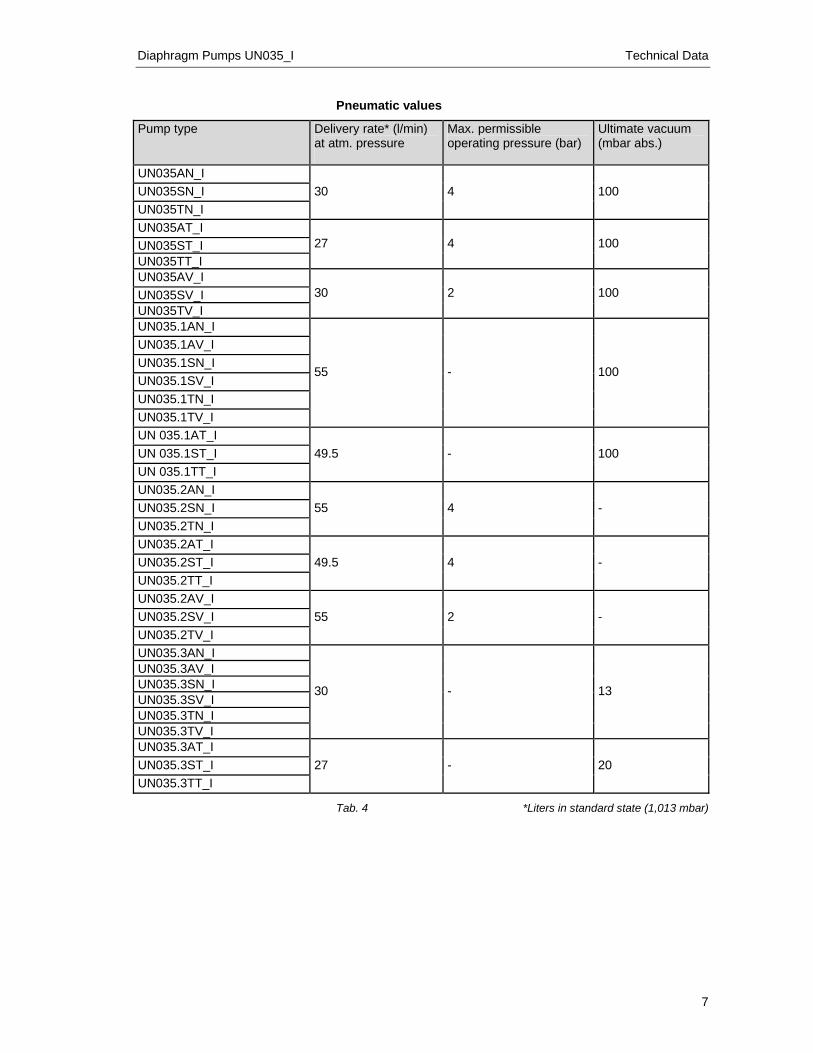
Pneumatic values
Pump type Delivery rate* (l/min) at atm. pressure
Max. permissible operating pressure (bar)
Ultimate vacuum (mbar abs.)
UN035AN_I 30 4 100 UN035SN_I
UN035TN_I UN035AT_I
27 4 100 UN035ST_I UN035TT_I UN035AV_I
30 2 100 UN035SV_I UN035TV_I UN035.1AN_I
55 - 100
UN035.1AV_I UN035.1SN_I UN035.1SV_I UN035.1TN_I UN035.1TV_I UN 035.1AT_I
49.5 - 100 UN 035.1ST_I UN 035.1TT_I UN035.2AN_I
55 4 - UN035.2SN_I UN035.2TN_I UN035.2AT_I
49.5 4 - UN035.2ST_I UN035.2TT_I UN035.2AV_I
55 2 - UN035.2SV_I UN035.2TV_I UN035.3AN_I
30 - 13
UN035.3AV_I UN035.3SN_I UN035.3SV_I UN035.3TN_I UN035.3TV_I UN035.3AT_I
27 - 20 UN035.3ST_I UN035.3TT_I
Tab. 4 *Liters in standard state (1,013 mbar)
Technical Data Diaphragm Pump UN035_I
8
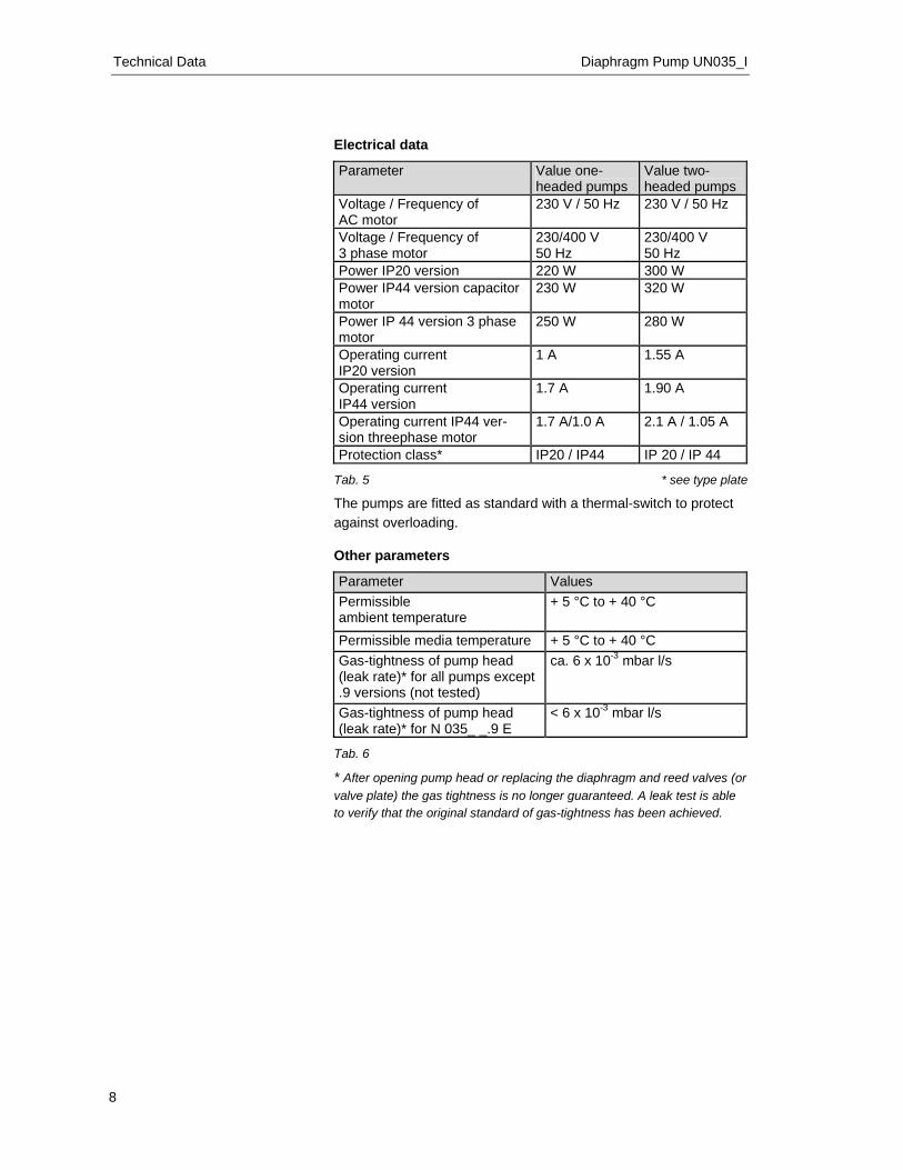
Electrical data
Parameter Value one-headed pumps
Value two-headed pumps
Voltage / Frequency of AC motor
230 V / 50 Hz 230 V / 50 Hz
Voltage / Frequency of 3 phase motor
230/400 V 50 Hz
230/400 V 50 Hz
Power IP20 version 220 W 300 W Power IP44 version capacitor motor
230 W 320 W
Power IP 44 version 3 phase motor
250 W 280 W
Operating current IP20 version
1 A 1.55 A
Operating current IP44 version
1.7 A 1.90 A
Operating current IP44 ver-sion threephase motor
1.7 A/1.0 A 2.1 A / 1.05 A
Protection class* IP20 / IP44 IP 20 / IP 44 Tab. 5 * see type plate
The pumps are fitted as standard with a thermal-switch to protect against overloading. Other parameters
Parameter Values Permissible ambient temperature
+ 5 °C to + 40 °C
Permissible media temperature + 5 °C to + 40 °C Gas-tightness of pump head (leak rate)* for all pumps except .9 versions (not tested)
ca. 6 x 10⁻³ mbar l/s
Gas-tightness of pump head (leak rate)* for N 035_ _.9 E
< 6 x 10⁻³ mbar l/s
Tab. 6
* After opening pump head or replacing the diaphragm and reed valves (or valve plate) the gas tightness is no longer guaranteed. A leak test is able to verify that the original standard of gas-tightness has been achieved.
Diaphragm Pumps UN035_I Design and Function
9
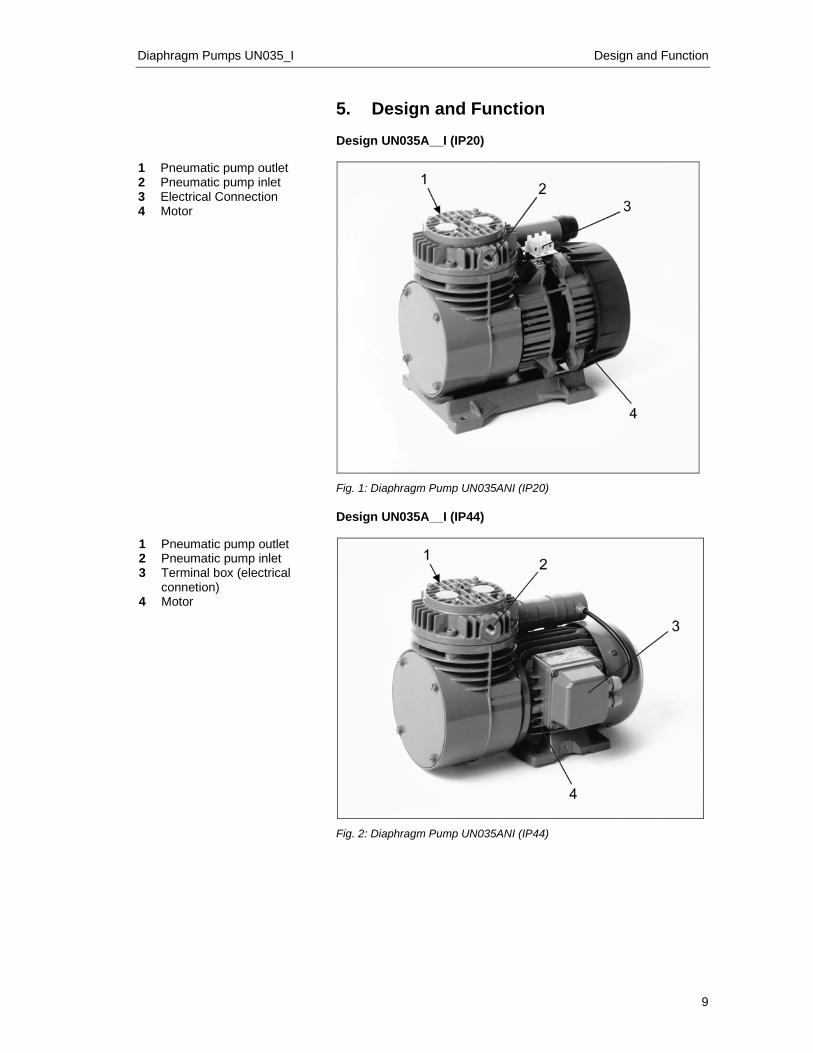
5. Design and Function Design UN035A__I (IP20)
1 Pneumatic pump outlet 2 Pneumatic pump inlet 3 Electrical Connection 4 Motor
Fig. 1: Diaphragm Pump UN035ANI (IP20) Design UN035A__I (IP44)
1 Pneumatic pump outlet 2 Pneumatic pump inlet 3 Terminal box (electrical
connetion) 4 Motor
Fig. 2: Diaphragm Pump UN035ANI (IP44)
Design and Function Diaphragm Pump UN035_I
10
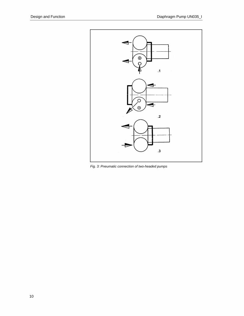
Fig. 3: Pneumatic connection of two-headed pumps
Diaphragm Pumps UN035_I Design and Function
11
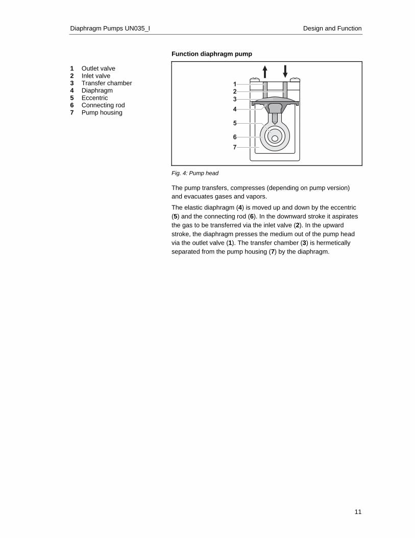
Function diaphragm pump
1 Outlet valve 2 Inlet valve 3 Transfer chamber 4 Diaphragm 5 Eccentric 6 Connecting rod 7 Pump housing
Fig. 4: Pump head The pump transfers, compresses (depending on pump version) and evacuates gases and vapors.
The elastic diaphragm (4) is moved up and down by the eccentric (5) and the connecting rod (6). In the downward stroke it aspirates the gas to be transferred via the inlet valve (2). In the upward stroke, the diaphragm presses the medium out of the pump head via the outlet valve (1). The transfer chamber (3) is hermetically separated from the pump housing (7) by the diaphragm.
Installation and connection Diaphragm Pump UN035_I
12
6. Installation and connection Only install and operate the pumps under the operating parameters and conditions described in chapter 4, Technical data.
Observe the safety precautions (see chapter 3). 6.1. Installation of the pump
Before installation, store the pump at the installation location to bring it up to room temperature.
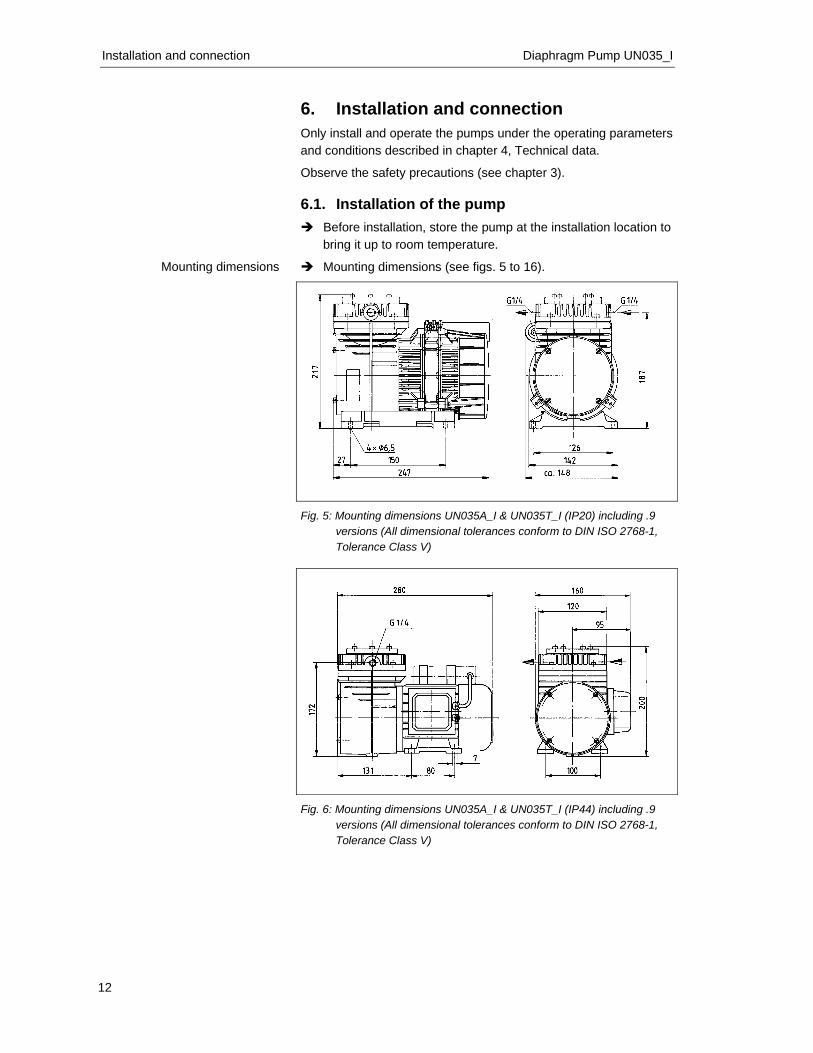
Mounting dimensions (see figs. 5 to 16).
Fig. 5: Mounting dimensions UN035A_I & UN035T_I (IP20) including .9
versions (All dimensional tolerances conform to DIN ISO 2768-1, Tolerance Class V)
Fig. 6: Mounting dimensions UN035A_I & UN035T_I (IP44) including .9
versions (All dimensional tolerances conform to DIN ISO 2768-1, Tolerance Class V)
Mounting dimensions
Diaphragm Pumps UN035_I Installation and connection
13
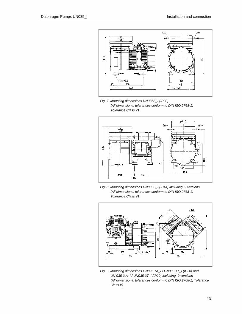
Fig. 7: Mounting dimensions UN035S_I (IP20)
(All dimensional tolerances conform to DIN ISO 2768-1, Tolerance Class V)
Fig. 8: Mounting dimensions UN035S_I (IP44) including .9 versions
(All dimensional tolerances conform to DIN ISO 2768-1, Tolerance Class V)
Fig. 9: Mounting dimensions UN035.1A_I / UN035.1T_I (IP20) and UN 035.3 A_I / UN035.3T_I (IP20) including .9 versions (All dimensional tolerances conform to DIN ISO 2768-1, Tolerance Class V)
Installation and connection Diaphragm Pump UN035_I
14
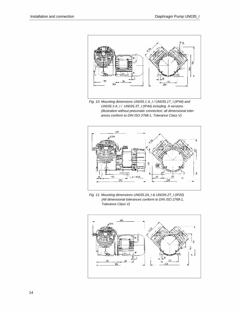
Fig. 10: Mounting dimensions UN035.1 A_I / UN035.1T_I (IP44) and UN035.3 A_I / UN035.3T_I (IP44) including .9 versions (illustration without pneumatic connection; all dimensional toler-ances conform to DIN ISO 2768-1, Tolerance Class V)
Fig. 11: Mounting dimensions UN035.2A_I & UN035.2T_I (IP20) (All dimensional tolerances conform to DIN ISO 2768-1, Tolerance Class V)
Diaphragm Pumps UN035_I Installation and connection
15
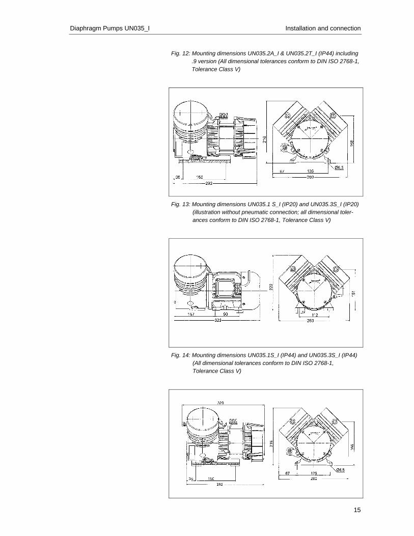
Fig. 12: Mounting dimensions UN035.2A_I & UN035.2T_I (IP44) including .9 version (All dimensional tolerances conform to DIN ISO 2768-1, Tolerance Class V)
Fig. 13: Mounting dimensions UN035.1 S_I (IP20) and UN035.3S_I (IP20) (illustration without pneumatic connection; all dimensional toler-ances conform to DIN ISO 2768-1, Tolerance Class V)
Fig. 14: Mounting dimensions UN035.1S_I (IP44) and UN035.3S_I (IP44) (All dimensional tolerances conform to DIN ISO 2768-1, Tolerance Class V)
Installation and connection Diaphragm Pump UN035_I
16
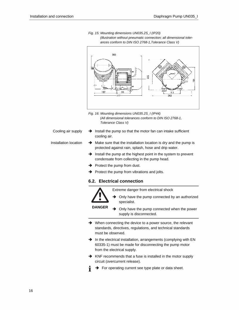
Fig. 15: Mounting dimensions UN035.2S_I (IP20)
(illustration without pneumatic connection; all dimensional toler-ances conform to DIN ISO 2768-1,Tolerance Class V)
Fig. 16: Mounting dimensions UN035.2S_I (IP44)
(All dimensional tolerances conform to DIN ISO 2768-1, Tolerance Class V)
Install the pump so that the motor fan can intake sufficient
cooling air.
Make sure that the installation location is dry and the pump is protected against rain, splash, hose and drip water.
Install the pump at the highest point in the system to prevent condensate from collecting in the pump head.
Protect the pump from dust.
Protect the pump from vibrations and jolts. 6.2. Electrical connection
DANGER
Extreme danger from electrical shock
Only have the pump connected by an authorized specialist.
Only have the pump connected when the power supply is disconnected.
When connecting the device to a power source, the relevant
standards, directives, regulations, and technical standards must be observed.
In the electrical installation, arrangements (complying with EN 60335-1) must be made for disconnecting the pump motor from the electrical supply.
KNF recommends that a fuse is installed in the motor supply circuit (overcurrent release).
For operating current see type plate or data sheet.
Cooling air supply
Installation location
Diaphragm Pumps UN035_I Installation and connection
17
Connecting pump
1. Compare the supply data with the data on the motor-plate. For operating current see type plate.
The voltage must not vary by more than + 10% and - 10% from that shown on the type-plate.
2. For IP 44 versions: open terminal box cover.
3. All pumps except versions with 3 phase motor: Connect the mains cables to the connections L1 and N of the pump motor.
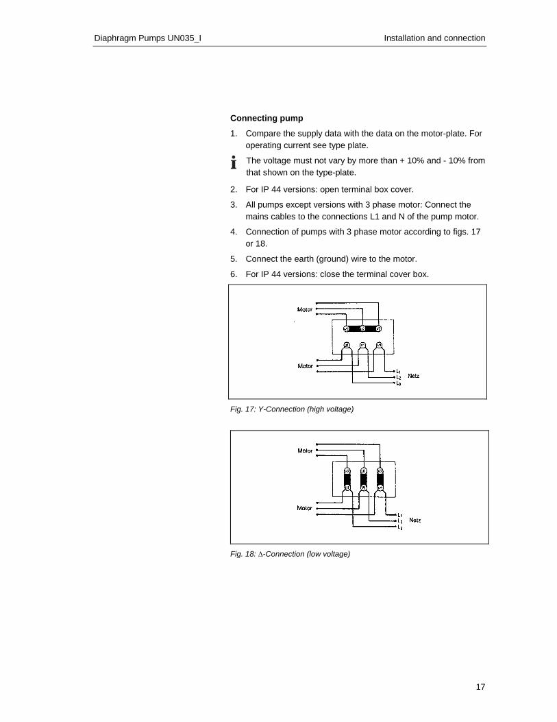
4. Connection of pumps with 3 phase motor according to figs. 17 or 18.
5. Connect the earth (ground) wire to the motor.
6. For IP 44 versions: close the terminal cover box.
Fig. 17: Y-Connection (high voltage)
Fig. 18: ∆-Connection (low voltage)
Installation and connection Diaphragm Pump UN035_I
18
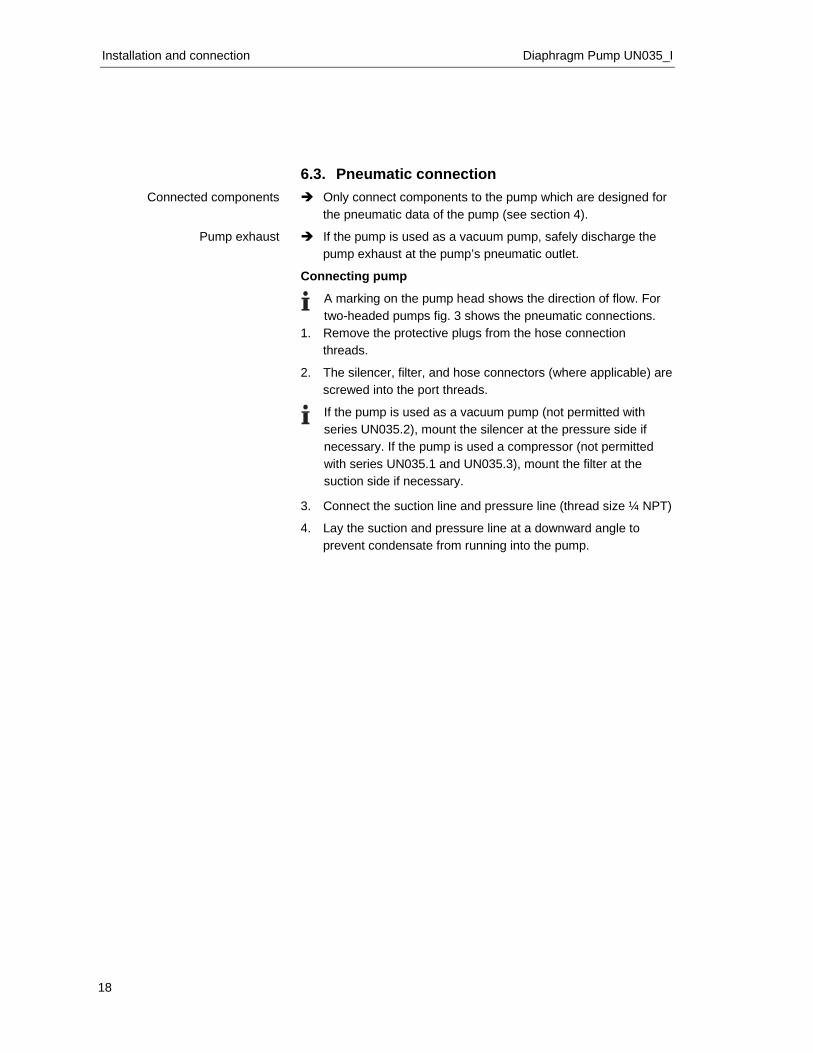
6.3. Pneumatic connection Only connect components to the pump which are designed for
the pneumatic data of the pump (see section 4).
If the pump is used as a vacuum pump, safely discharge the pump exhaust at the pump’s pneumatic outlet.
Connecting pump
A marking on the pump head shows the direction of flow. For two-headed pumps fig. 3 shows the pneumatic connections.
1. Remove the protective plugs from the hose connection threads.
2. The silencer, filter, and hose connectors (where applicable) are screwed into the port threads.
If the pump is used as a vacuum pump (not permitted with series UN035.2), mount the silencer at the pressure side if necessary. If the pump is used a compressor (not permitted with series UN035.1 and UN035.3), mount the filter at the suction side if necessary.
3. Connect the suction line and pressure line (thread size ¼ NPT)
4. Lay the suction and pressure line at a downward angle to prevent condensate from running into the pump.
Connected components
Pump exhaust
Diaphragm Pumps UN035_I Operation
19
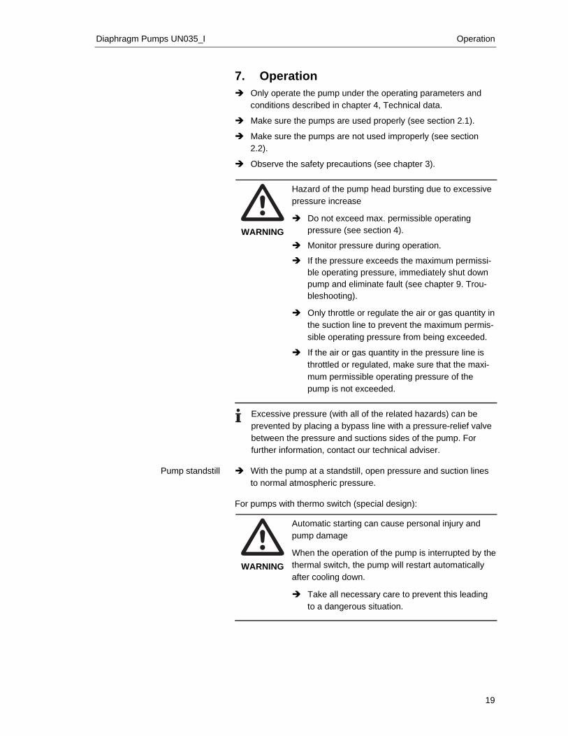
7. Operation Only operate the pump under the operating parameters and
conditions described in chapter 4, Technical data.
Make sure the pumps are used properly (see section 2.1).
Make sure the pumps are not used improperly (see section 2.2).
Observe the safety precautions (see chapter 3).
WARNING
Hazard of the pump head bursting due to excessive pressure increase
Do not exceed max. permissible operating pressure (see section 4).
Monitor pressure during operation.
If the pressure exceeds the maximum permissi-ble operating pressure, immediately shut down pump and eliminate fault (see chapter 9. Trou-bleshooting).
Only throttle or regulate the air or gas quantity in
the suction line to prevent the maximum permis-sible operating pressure from being exceeded.
If the air or gas quantity in the pressure line is throttled or regulated, make sure that the maxi-mum permissible operating pressure of the pump is not exceeded.
Excessive pressure (with all of the related hazards) can be prevented by placing a bypass line with a pressure-relief valve between the pressure and suctions sides of the pump. For further information, contact our technical adviser.
With the pump at a standstill, open pressure and suction lines
to normal atmospheric pressure. For pumps with thermo switch (special design):
WARNING
Automatic starting can cause personal injury and pump damage When the operation of the pump is interrupted by the thermal switch, the pump will restart automatically after cooling down.
Take all necessary care to prevent this leading to a dangerous situation.
Pump standstill
Operation Diaphragm Pump UN035_I
20
Switching pump on
The pump may not start up against pressure or vacuum during switch-on. This also applies in operation following a brief power failure.
Make sure that no pressure is present in the lines during switch-on.
Switching off the pump
KNF recommends: When transferring aggressive media, flush the pump prior to switch-off to increase the service life of the diaphragm (see section 8.2.1).
Open pressure and suction lines to normal atmospheric pres-sure.
Diaphragm Pumps UN035_I Servicing
21
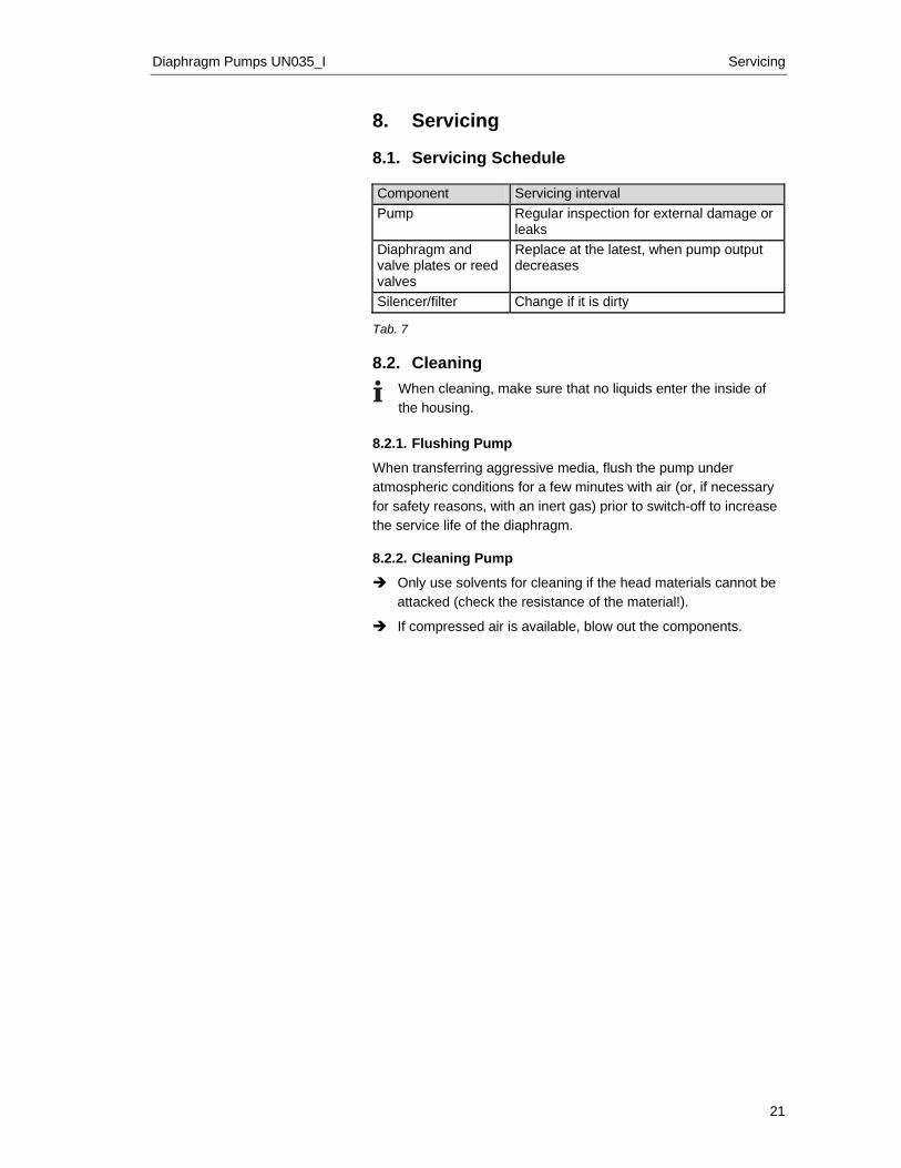
8. Servicing 8.1. Servicing Schedule Component Servicing interval Pump Regular inspection for external damage or
leaks Diaphragm and valve plates or reed valves
Replace at the latest, when pump output decreases
Silencer/filter Change if it is dirty Tab. 7 8.2. Cleaning
When cleaning, make sure that no liquids enter the inside of the housing.
8.2.1. Flushing Pump
When transferring aggressive media, flush the pump under atmospheric conditions for a few minutes with air (or, if necessary for safety reasons, with an inert gas) prior to switch-off to increase the service life of the diaphragm. 8.2.2. Cleaning Pump
Only use solvents for cleaning if the head materials cannot be attacked (check the resistance of the material!).
If compressed air is available, blow out the components.
Servicing Diaphragm Pump UN035_I
22
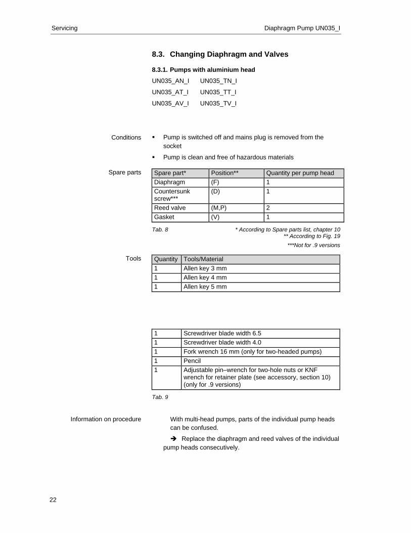
8.3. Changing Diaphragm and Valves 8.3.1. Pumps with aluminium head
UN035_AN_I UN035_TN_I
UN035_AT_I UN035_TT_I
UN035_AV_I UN035_TV_I
Pump is switched off and mains plug is removed from the socket
Pump is clean and free of hazardous materials Spare part* Position** Quantity per pump head Diaphragm (F) 1 Countersunk screw***
(D) 1
Reed valve (M,P) 2 Gasket (V) 1
Tab. 8 * According to Spare parts list, chapter 10
** According to Fig. 19 ***Not for .9 versions
Quantity Tools/Material 1 Allen key 3 mm 1 Allen key 4 mm 1 Allen key 5 mm
1 Screwdriver blade width 6.5 1 Screwdriver blade width 4.0 1 Fork wrench 16 mm (only for two-headed pumps) 1 Pencil 1 Adjustable pin–wrench for two-hole nuts or KNF
wrench for retainer plate (see accessory, section 10) (only for .9 versions)
Tab. 9
With multi-head pumps, parts of the individual pump heads can be confused.
Replace the diaphragm and reed valves of the individual pump heads consecutively.
Conditions
Spare parts
Tools
Information on procedure
Diaphragm Pumps UN035_I Servicing
23
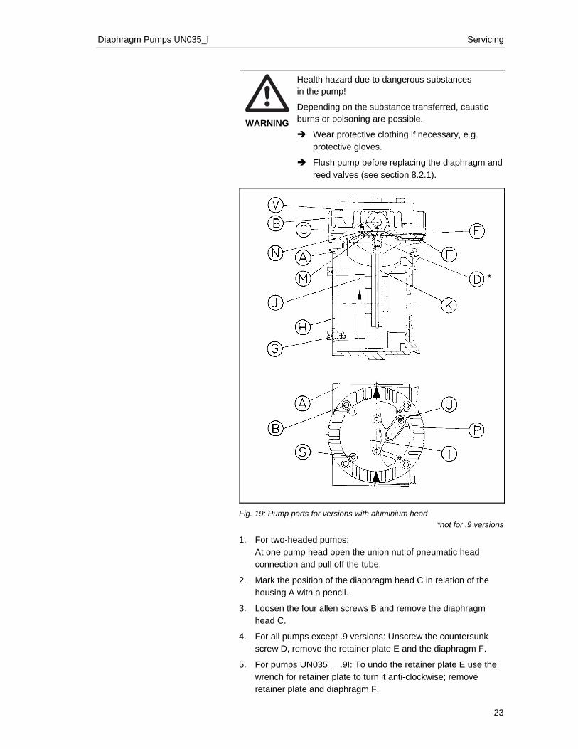
WARNING
Health hazard due to dangerous substances in the pump!
Depending on the substance transferred, caustic burns or poisoning are possible.
Wear protective clothing if necessary, e.g. protective gloves.
Flush pump before replacing the diaphragm and reed valves (see section 8.2.1).
*
Fig. 19: Pump parts for versions with aluminium head
*not for .9 versions
1. For two-headed pumps: At one pump head open the union nut of pneumatic head connection and pull off the tube.
2. Mark the position of the diaphragm head C in relation of the housing A with a pencil.
3. Loosen the four allen screws B and remove the diaphragm head C.
4. For all pumps except .9 versions: Unscrew the countersunk screw D, remove the retainer plate E and the diaphragm F.
5. For pumps UN035_ _.9I: To undo the retainer plate E use the wrench for retainer plate to turn it anti-clockwise; remove retainer plate and diaphragm F.
Servicing Diaphragm Pump UN035_I
24
6. Loosen the four screws G and remove the cover plate H.
7. Turn the counterweight J so that the connection rod K is in the mid-position; fit the new diaphragm F.
8. For all pumps except .9 versions: Place the retainer plate E on the diaphragm F and tighten the new countersunk screw D (torque: 5.0 Nm).
The self-locking screw D can only be used once.
9. For pumps UN035_ _.9I: Place the retainer plate E on the diaphragm F. Screw on the retainer plate E with the wrench for retainer plate uniformly and diagonally (torque: 5.0 Nm).
10. Change lower reed valve:
− Undo the cheese head screw N and exchange the reed valve M.
11. Change upper reed valve:
− Loosen the allen screws S, remove the cover plate T and the gasket V.
− Undo the cheese head screw U and exchange the reed valve P; tighten the cheese head screw U.
− Replace the cover plate T with a new gasket V and tighten the allen screws S.
12. Place the diaphragm head C on the diaphragm F according to the marks made previously and tighten the screws B uniformly and diagonally (torque: 10.0 Nm).
13. Turn the counterweight J to check that the pump run freely, replace the cover plate H and secure it with the four screws G.
14. For two-headed pumps: Carry out steps 2 to 13 for the second pump head.
15. For two-headed pumps: Reattach the tube of pneumatic head connection onto the hose connector and tighten the union nut.
Diaphragm Pumps UN035_I Servicing
25
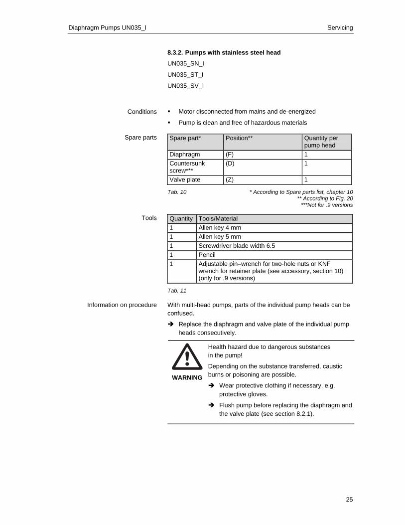
8.3.2. Pumps with stainless steel head
UN035_SN_I
UN035_ST_I
UN035_SV_I Motor disconnected from mains and de-energized
Pump is clean and free of hazardous materials Spare part* Position** Quantity per
pump head Diaphragm (F) 1 Countersunk screw***
(D) 1
Valve plate (Z) 1 Tab. 10 * According to Spare parts list, chapter 10
** According to Fig. 20 ***Not for .9 versions
Quantity Tools/Material 1 Allen key 4 mm 1 Allen key 5 mm 1 Screwdriver blade width 6.5 1 Pencil 1 Adjustable pin–wrench for two-hole nuts or KNF
wrench for retainer plate (see accessory, section 10) (only for .9 versions)
Tab. 11 With multi-head pumps, parts of the individual pump heads can be confused.
Replace the diaphragm and valve plate of the individual pump heads consecutively.
WARNING
Health hazard due to dangerous substances in the pump!
Depending on the substance transferred, caustic burns or poisoning are possible.
Wear protective clothing if necessary, e.g. protective gloves.
Flush pump before replacing the diaphragm and the valve plate (see section 8.2.1).
Conditions
Spare parts
Tools
Information on procedure
Servicing Diaphragm Pump UN035_I
26
*
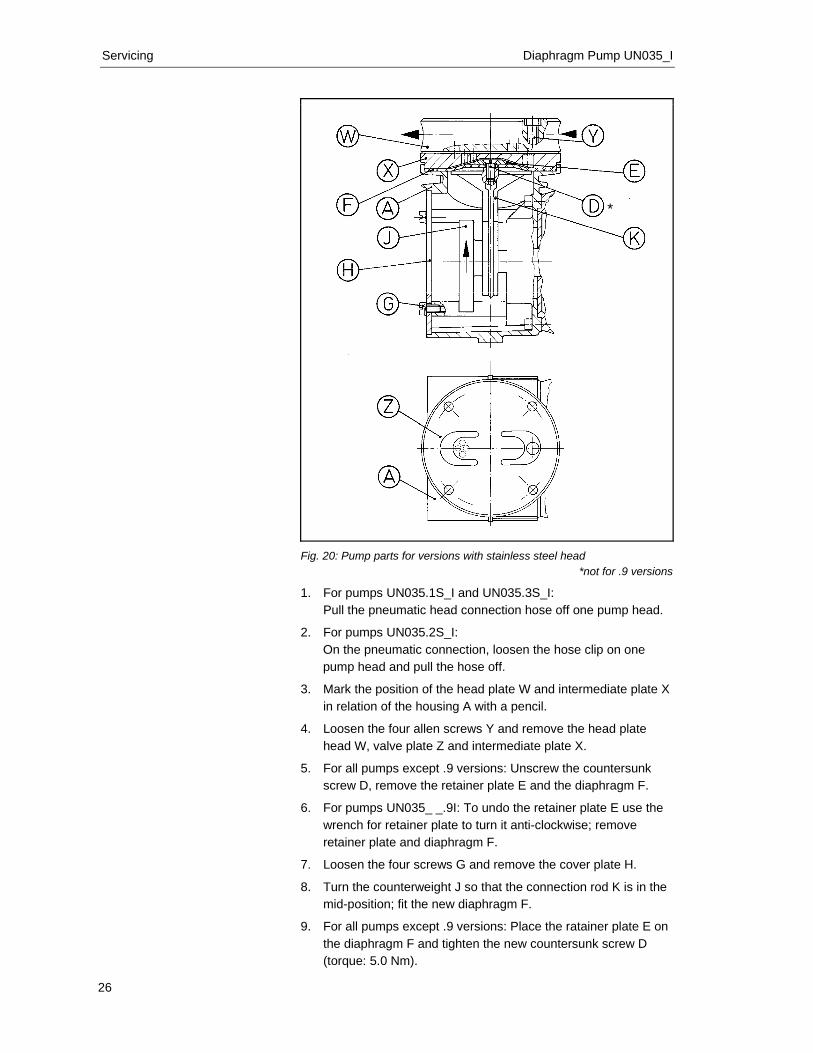
Fig. 20: Pump parts for versions with stainless steel head
*not for .9 versions
1. For pumps UN035.1S_I and UN035.3S_I: Pull the pneumatic head connection hose off one pump head.
2. For pumps UN035.2S_I: On the pneumatic connection, loosen the hose clip on one pump head and pull the hose off.
3. Mark the position of the head plate W and intermediate plate X in relation of the housing A with a pencil.
4. Loosen the four allen screws Y and remove the head plate head W, valve plate Z and intermediate plate X.
5. For all pumps except .9 versions: Unscrew the countersunk screw D, remove the retainer plate E and the diaphragm F.
6. For pumps UN035_ _.9I: To undo the retainer plate E use the wrench for retainer plate to turn it anti-clockwise; remove retainer plate and diaphragm F.
7. Loosen the four screws G and remove the cover plate H.
8. Turn the counterweight J so that the connection rod K is in the mid-position; fit the new diaphragm F.
9. For all pumps except .9 versions: Place the ratainer plate E on the diaphragm F and tighten the new countersunk screw D (torque: 5.0 Nm).
Diaphragm Pumps UN035_I Servicing
27
The self-locking screw D can only be used once.
10. For pumps UN035_ _.9I: Place the retainer plate E on the diaphragm F. Screw on the retainer plate E with the wrench for retainer plate uniformly and diagonally (torque: 5.0 Nm).
11. Place the intermediate plate X on the top of the diaphragm F
so that it corresponds to the marks on the housing.
12. Place the new valve plate Z on the intermediate plate X.
13. Place the head plate head W on the diaphragm F according to the marks made previously and tighten the screws Y uniformly and diagonally (torque: 10.0 Nm).
14. Turn the counterweight J to check that the pump run freely, replace the cover plate H and secure it with the four screws G.
15. For two-headed pumps: Carry out steps 3 to 14 for the second pump head.
16. For two-headed pumps: Pull the pneumatic head connection hose back onto the hose connector.
17. For pump type UN035.2S_I: Retighten the hose clip on the pneumatic head connection.
Troubleshooting Diaphragm Pump UN035_I
28
9. Troubleshooting
DANGER
Extreme danger from electrical shock!
Disconnect the pump power supply before working on the pump.
Make sure the pump is de-energized and secure.
Check the pump (see Tab. 12 and 13).
Pump does not transfer
Cause Fault remedy No voltage in the power source Check room fuse and switch on if necessary.
Connections or lines blocked. Check connections and lines. Remove blockage.
External valve is closed or filter is clogged.
Check external valves and filters.
Condensate has collected in pump head.
Flush pump (see Section 8.2.1). Install pump at highest point in system.
Diaphragm or reed valves (valve plate) are worn.
Replace diaphragm and reed valves (valve plate), (see Section 8.3).
Tab. 12
Flow rate, pressure or vacuum too low
The pump does not achieve the output specified in the Technical data or the data sheet. Cause Fault remedy Condensate has collected in pump head.
Flush pump (see Section 8.2.1). Install pump at highest point in system.
There is gauge pressure on pressure side and at the same time vacuum or a pressure above atmospheric pressure on suction side.
Change the pressure conditions.
Pneumatic lines or connection parts have an insufficient cross section.
Disconnect pump from system to determine output values. Eliminate throttling (e.g. valve) if necessary. Use lines or connection parts with larger cross section if
necessary. Leaks occur on connections, lines or pump head.
Eliminate leaks.
Connections or lines completely or partially jammed.
Check connections and lines. Remove the jamming parts and particles.
Head parts are soiled. Clean head components. Diaphragm or reed valves (valve plate) are worn.
Replace diaphragm and reed valves (valve plate), (see Section 8.3).
Tab. 13
Diaphragm Pumps UN035_I Troubleshooting
29
Fault cannot be rectified
If you are unable to determine any of the specified causes, send the pump to KNF Customer Service (see first page for the ad-dress).
1. Flush the pump to free the pump head of dangerous or ag-gressive gases (see Section 8.2.1).
2. Remove the pump.
3. Clean the pump (see Section 8.2.2).
4. Send the pump to KNF with a filled out decontamination decla-ration (see chapter 11) and specification of the medium trans-ferred.
Spare parts and accessories Diaphragm Pump UN035_I
30
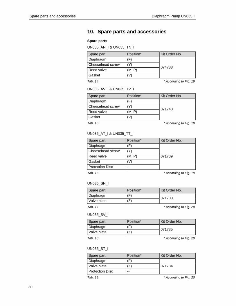
10. Spare parts and accessories Spare parts
UN035_AN_I & UN035_TN_I
Spare part Position* Kit Order No. Diaphragm (F)
074738 Cheesehead screw (Y) Reed valve (M, P) Gasket (V)
Tab. 14 * According to Fig. 19 UN035_AV_I & UN035_TV_I
Spare part Position* Kit Order No. Diaphragm (F)
071740 Cheesehead screw (Y) Reed valve (M, P) Gasket (V)
Tab. 15 * According to Fig. 19
UN035_AT_I & UN035_TT_I
Spare part Position* Kit Order No. Diaphragm (F)
071739 Cheesehead screw (Y) Reed valve (M, P) Gasket (V) Protection Disc --
Tab. 16 * According to Fig. 19
UN035_SN_I
Spare part Position* Kit Order No. Diaphragm (F)
071733 Valve plate (Z)
Tab. 17 * According to Fig. 20 UN035_SV_I
Spare part Position* Kit Order No. Diaphragm (F)
071735 Valve plate (Z)
Tab. 18 * According to Fig. 20
UN035_ST_I
Spare part Position* Kit Order No. Diaphragm (F)
071734 Valve plate (Z) Protection Disc --
Tab. 19 * According to Fig. 20
Diaphragm Pumps UN035_I Product Return
31
11. Product Return KNF provides warranty and non-warranty repair services for all
products.
A Return Material Authorization (RMA) number is required for all product returns.
• To receive an RMA number, submit a completed Decontamination Declaration form to [email protected]
The Decontamination Declaration form can obtained from our website or by contacting KNF Technical Services.
• http://www.knf.com/pdfs/decontamdec.doc
• Phone: 609-890-8600
Product return instructions will be provided when the RMA is issued.
KNF Neuberger, Inc 2 Black Forest Rd Trenton, NJ 08691-1810
Phone 609-890-8600 Fax 609-890-8323
www.knf.com/usa.htm

32