Embed Size (px)
Citation preview
Photocatalytic modification of bioactive molecules incontinuous-flow microreactorsCitation for published version (APA):Bottecchia, C. (2019). Photocatalytic modification of bioactive molecules in continuous-flow microreactors.Eindhoven: Technische Universiteit Eindhoven.
Document status and date:Published: 20/02/2019
Document Version:Publisher’s PDF, also known as Version of Record (includes final page, issue and volume numbers)
Please check the document version of this publication:
• A submitted manuscript is the version of the article upon submission and before peer-review. There can beimportant differences between the submitted version and the official published version of record. Peopleinterested in the research are advised to contact the author for the final version of the publication, or visit theDOI to the publisher's website.• The final author version and the galley proof are versions of the publication after peer review.• The final published version features the final layout of the paper including the volume, issue and pagenumbers.Link to publication
General rightsCopyright and moral rights for the publications made accessible in the public portal are retained by the authors and/or other copyright ownersand it is a condition of accessing publications that users recognise and abide by the legal requirements associated with these rights.
• Users may download and print one copy of any publication from the public portal for the purpose of private study or research. • You may not further distribute the material or use it for any profit-making activity or commercial gain • You may freely distribute the URL identifying the publication in the public portal.
If the publication is distributed under the terms of Article 25fa of the Dutch Copyright Act, indicated by the “Taverne” license above, pleasefollow below link for the End User Agreement:www.tue.nl/taverne
Take down policyIf you believe that this document breaches copyright please contact us at:[email protected] details and we will investigate your claim.
Download date: 13. Jul. 2020
Photocatalytic modification of bioactive molecules in
continuous-flow microreactors
Cecilia Bottecchia
Cecilia Bottecchia
Photocatalytic modification of bioactive molecules in continuous-flow microreactors
The work described in this thesis has been carried out within the Micro Flow
Chemistry and Synthetic Methodology group, at the Eindhoven University of
Technology, The Netherlands. This research was financially supported by the
European Union’s Horizon 2020 research and innovation program via a Marie
Sklodowska-Curie grant (641861).
A catalogue record is available from the Eindhoven University of Technology
Library
ISBN: 978-90-386-4692-3
Copyright © 2019 by Cecilia Bottecchia
Printed by ProefschriftMaken, 2019
Cover design by Remco Wetzels, www.remcowetzels.nl
Photocatalytic modification of bioactive molecules in
continuous-flow microreactors
PROEFSCHRIFT
Ter verkrijging van de graad van doctor aan de Technische Universiteit Eindhoven,
op gezag van de rector magnificus prof.dr.ir. F.B.T. Baaijens, voor een commissie
aangewezen door het College voor Promoties, in het openbaar te verdedigen op
woensdag 20 februari 2019 om 11:00 uur
Door
Cecilia Bottecchia
geboren te Milaan, Italië
Dit proefschrift is goedgekeurd door de promotoren en de samenstelling van de
promotiecommissie is als volgt:
Voorzitter: prof.dr.ir. E.J.M. Hensen
Promotor: dr. T. Noël
Copromotor(en): prof.dr. F. Gallucci
Leden: prof.dr. A. Madder (Universiteit Gent)
prof.dr. J.G. Roelfes (RUG)
prof.dr. R.P. Sijbesma
prof.dr. J.H. van Maarseveen (UvA)
dr.ir. A.R.A. Palmans
Het onderzoek of ontwerp dat in dit proefschrift wordt beschreven is uitgevoerd
in overeenstemming met de TU/e Gedragscode Wetenschapsbeoefening
Table of Contents:
Chapter 1: Introduction to visible light photoredox catalysis
andcontinuous-flow chemistry
9
Chapter 2: Visible light-induced trifluoromethylation and
perfluoroalkylation of cysteine in batch and continuous
flow
53
Chapter 3: Batch and flow synthesis of disulfides by visible light
induced TiO2 photocatalysis
73
Chapter 4: Visible-light-mediated selective arylation of cysteine in
batch and flow
93
Chapter 5: Visible light induced trifluoromethylation of highly
functionalized arenes and heteroarenes in continuous
flow
117
Chapter 6: De novo design of organic photocatalysts: bithiophene
derivatives for the visible-light induced C-H
functionalization of heteroarenes
135
Chapter 7: A fully automated continuous-flow platform for
fluorescence quenching studies and Stern-Volmer
analysis
167
Conclusions and Summary 191
List of abbreviations 196
List of publications 199
Acknowledgements 201
About the author 203

“Pass on what you have learned.
Strength, mastery. But weakness, folly, failure also.
Yes, failure most of all. The greatest teacher, failure is.”
-Master Yoda
CHAPTER 1
Introduction to visible light photoredox catalysis and continuous-flow chemistry
This chapter is based on:
Bottecchia, C.; Noël, T. Photocatalytic modification of amino acids, peptides and proteins. Chem. – Eur. J. 2019, 25, 26-42.
Bottecchia, C.; Cambié, D.; Straathof, N. J. W.; Hessel, V.; Noël, T. Applications of continuous-flow photochemistry in organic synthesis, material science, and water treatment. Chem. Rev. 2016, 116, 10276-10341.
1
Introduction 11
PHOTOCHEMISTRY AND PHOTOCATALYSIS
Sunlight strikes our planet every hour with more energy than we consume in a
whole year.[1] Therefore, many researchers have explored ways to efficiently harvest
and use light energy for the activation of organic molecules.[2] Light activation of
molecules provides access to reaction pathways which are otherwise impossible
to reach with classical thermochemical activation.[3] Another fascinating aspect of
photochemistry is the use of photons as “traceless and green reagents”, hence
rendering photochemical processes green and sustainable.
However, up to date the use of sunlight to drive chemical reactions is still far from
reality. The main drawbacks preventing the widespread use of solar photochemistry
are the difficulty associated with the efficient harvesting of solar light and the
fluctuating nature of the radiation itself (e.g. its variability and irreproducibility
due to weather conditions or to the different geographical areas on the planet).[4] Nevertheless, significant advances have been recently reported thanks to the
implementation of continuous-flow reactors for solar photochemistry.[5] Thus, it is
expected that the technology necessary to enable solar photochemistry in organic
synthesis will soon be available.
A brief historical perspective of photochemistry
The first experimental account of a chemical modification induced by light dates
back to 1834, when Hermann Trommsdorff described the effects of sunlight
exposure on α-santonin crystals, a sesquiterpene lactone used as febrifuge and
isolated from Artemisia plants.[6] Remarkably, through the use of a prism, he
understood the dependence of the wavelength on the crystal decomposition
(“santonin is turned yellow not only by the undivided, but also by the blue and
violet rays… whereas… the yellow, green and red ones cause not even the slightest
changes”).[7] The photodegradation of santonin was further investigated by another
pioneer of photochemistry, Stanislao Cannizzaro.[8] Starting from his seminal
work, his disciples Paternó, Ciamician and Silber took the first steps towards
modern photochemistry. Paternó first discovered in 1909 the eponym [2+2]
photocycloaddition between alkenes and carbonyls, further expanded by Büchi.[9]
Around the same period, Giacomo Ciamician and Paolo Silber laid the foundation
of modern photochemistry through a systematic investigation of photochemical
reactions (photoreductions[10], photocycloadditions[11], α- and β-cleavage of
ketones[12]).[13]
1
12 Chapter 1 Introduction 13
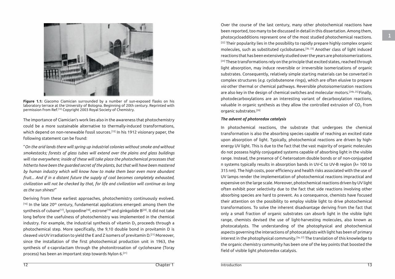
Figure 1.1: Giacomo Ciamician surrounded by a number of sun-exposed flasks on his laboratory terrace at the University of Bologna. Beginning of 20th century. Reprinted with permission from Ref.[14] Copyright 2003 Royal Society of Chemistry.
The importance of Ciamician’s work lies also in the awareness that photochemistry
could be a more sustainable alternative to thermally-induced transformations,
which depend on non-renewable fossil sources.[15] In his 1912 visionary paper, the
following statement can be found:
“On the arid lands there will spring up industrial colonies without smoke and without
smokestacks; forests of glass tubes will extend over the plains and glass buildings
will rise everywhere; inside of these will take place the photochemical processes that
hitherto have been the guarded secret of the plants, but that will have been mastered
by human industry which will know how to make them bear even more abundant
fruit... And if in a distant future the supply of coal becomes completely exhausted,
civilization will not be checked by that, for life and civilization will continue as long
as the sun shines!”
Deriving from these earliest approaches, photochemistry continuously evolved.[16] In the late 20th century, fundamental applications emerged: among them the
synthesis of cubane[17], lycopodine[18], estrone[19] and ginkgolide B[20]. It did not take
long before the usefulness of photochemistry was implemented in the chemical
industry. For example, the industrial synthesis of vitamin D3 proceeds through a
photochemical step. More specifically, the 9,10 double bond in provitamin D is
cleaved via UV irradiation to yield the E and Z isomers of previtamin D.[21] Moreover,
since the installation of the first photochemical production unit in 1963, the
synthesis of ε-caprolactam through the photonitrosation of cyclohexane (Toray
process) has been an important step towards Nylon 6.[21]
Over the course of the last century, many other photochemical reactions have
been reported, too many to be discussed in detail in this dissertation. Among them,
photocycloadditions represent one of the most studied photochemical reactions.[22] Their popularity lies in the possibility to rapidly prepare highly complex organic
molecules, such as substituted cyclobutanes.[3b, 23] Another class of light induced
reactions that has been extensively studied over the years are photoisomerizations.[24] These transformations rely on the principle that excited states, reached through
light absorption, may induce reversible or irreversible isomerizations of organic
substrates. Consequently, relatively simple starting materials can be converted in
complex structures (e.g. cyclobutenone rings), which are often elusive to prepare
via other thermal or chemical pathways. Reversible photoisomerization reactions
are also key in the design of chemical switches and molecular motors.[24b, 25] Finally,
photodecarboxylations are an interesting variant of decarboxylation reactions,
valuable in organic synthesis as they allow the controlled extrusion of CO2 from
organic substrates.[26]
The advent of photoredox catalysis
In photochemical reactions, the substrate that undergoes the chemical
transformation is also the absorbing species capable of reaching an excited state
upon absorption of light. Typically, photochemical reactions are driven by high-
energy UV light. This is due to the fact that the vast majority of organic molecules
do not possess highly conjugated systems capable of absorbing light in the visible
range. Instead, the presence of C-heteroatom double bonds or of non-conjugated
π systems typically results in absorption bands in UV-C to UV-B region (λ= 100 to
315 nm). The high costs, poor efficiency and health risks associated with the use of
UV lamps render the implementation of photochemical reactions impractical and
expensive on the large scale. Moreover, photochemical reactions driven by UV light
often exhibit poor selectivity due to the fact that side reactions involving other
absorbing species are hard to prevent. As a consequence, chemists have focused
their attention on the possibility to employ visible light to drive photochemical
transformations. To solve the inherent disadvantage deriving from the fact that
only a small fraction of organic substrates can absorb light in the visible light
range, chemists devised the use of light-harvesting molecules, also known as
photocatalysts. The understanding of the photophysical and photochemical
aspects governing the interactions of photocatalysts with light has been of primary
interest in the photophysical community.[3a, 27] The translation of this knowledge to
the organic chemistry community has been one of the key points that boosted the
field of visible light photoredox catalysis.
1
14 Chapter 1 Introduction 15
In the late 70’s, seminal work from Kellogg and co-workers demonstrated how,
upon visible-light absorption, ruthenium metal-based complexes can efficiently
fulfil the role of photocatalyst by engaging in redox processes with the substrate
of interest.[28] Around the same time, other publications confirmed that similar Ru
species could participate in the visible-light induced reduction of a wide range of
organic substrates (e.g. benzylic and phenacyl halides, electron deficient olefins
and aromatic ketones).[29] The first researcher that appreciated the potential of the
Ru photocatalytic systems for reductive intermolecular and intramolecular bond
formation were Deronzier and Okada.[30] Despite these early findings, the field of
photoredox catalysis remained unexplored until the first decade of this century,
when the groups of Macmillan, Yoon and Stephenson showcased how varied the
redox reactivity of transition-metal based photocatalysts can be.[31]
Photoredox catalysis: basic principles
Owing to the generally mild reaction conditions (i.e. room temperature and
ambient pressure), the use of visible light as a perennial energy source and its broad
applicability, visible light photoredox catalysis has gained tremendous momentum
in the past decade, triggering a renewed interest towards photochemistry in
general.
In photoredox catalysis, the ability of transition metal-based or organic
photocatalysts to harvest visible light and convert it to an electrochemical potential
is exploited to activate organic substrates.[32] Specifically, upon absorption,
photocatalysts reach an excited state in which they are prone to engage in
single electron transfers (SETs) with organic substrates acting as either electron
donors or acceptors, thus de facto activating them and resulting in the formation
of radical intermediates (Scheme 1.4).[32-33] In order to best comprehend the
mechanisms involved in photoredox chemistry, an excursus on the photophysical
properties of commonly used photocatalysts appears necessary. For the purpose
of this discussion, the photophysical properties of the tris(bipyridine)ruthenium(II)
complex (i.e. Ru(bpy)32+) will be taken as example. Upon excitation by a photon
with energy corresponding to the band-gap of the photocatalyst (in the case
of Ru(bpy)32+ a photon with energy corresponding to blue light, λ ~ 450 nm), an
electron from the highest occupied molecular orbital (HOMO) is promoted to the
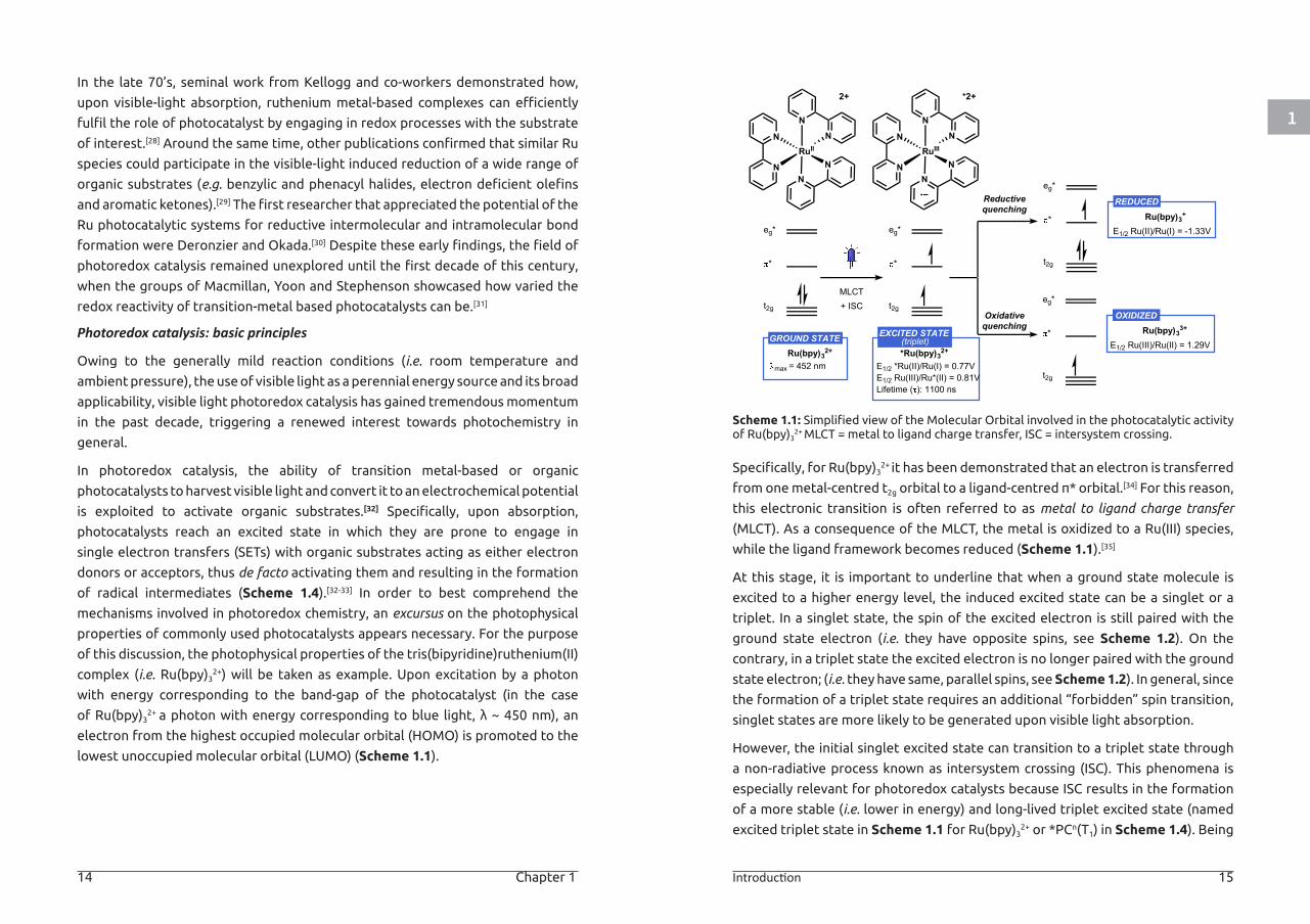
lowest unoccupied molecular orbital (LUMO) (Scheme 1.1).
Scheme 1.1: Simplified view of the Molecular Orbital involved in the photocatalytic activity of Ru(bpy)3
2+ MLCT = metal to ligand charge transfer, ISC = intersystem crossing.
Specifically, for Ru(bpy)32+ it has been demonstrated that an electron is transferred
from one metal-centred t2g orbital to a ligand-centred π* orbital.[34] For this reason,
this electronic transition is often referred to as metal to ligand charge transfer
(MLCT). As a consequence of the MLCT, the metal is oxidized to a Ru(III) species,
while the ligand framework becomes reduced (Scheme 1.1).[35]
At this stage, it is important to underline that when a ground state molecule is
excited to a higher energy level, the induced excited state can be a singlet or a
triplet. In a singlet state, the spin of the excited electron is still paired with the
ground state electron (i.e. they have opposite spins, see Scheme 1.2). On the
contrary, in a triplet state the excited electron is no longer paired with the ground
state electron; (i.e. they have same, parallel spins, see Scheme 1.2). In general, since
the formation of a triplet state requires an additional “forbidden” spin transition,
singlet states are more likely to be generated upon visible light absorption.
However, the initial singlet excited state can transition to a triplet state through
a non-radiative process known as intersystem crossing (ISC). This phenomena is
especially relevant for photoredox catalysts because ISC results in the formation
of a more stable (i.e. lower in energy) and long-lived triplet excited state (named
excited triplet state in Scheme 1.1 for Ru(bpy)32+ or *PCn(T1) in Scheme 1.4). Being
EXCITED STATE
eg*
*
t2g
eg*
*
t2g
eg*
*
t2g
eg*
*
t2g
MLCT+ ISC
N
N
RuII
NN
N
N
2+
N
N
RuIII
NN
N
N
*2+
Ru(bpy)32+ *Ru(bpy)32+
Ru(bpy)33+
Reductivequenching
Oxidativequenching
E1/2 *Ru(II)/Ru(I) = 0.77VE1/2 Ru(III)/Ru*(II) = 0.81VLifetime ( ): 1100 ns
max = 452 nm
GROUND STATE
OXIDIZED
E1/2 Ru(III)/Ru(II) = 1.29V
Ru(bpy)3+REDUCED
E1/2 Ru(II)/Ru(I) = -1.33V
(triplet)
1
16 Chapter 1 Introduction 17
spin-forbidden, the decay from the excited triplet state back to singlet ground
state is typically slower, which explains the long excited state lifetime of transition
metal-based photocatalysts.[32]
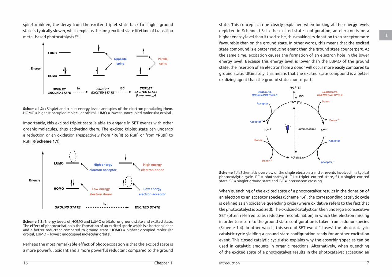
Scheme 1.2: : Singlet and triplet energy levels and spins of the electron populating them. HOMO = highest occupied molecular orbital LUMO = lowest unoccupied molecular orbital.
Importantly, this excited triplet state is able to engage in SET events with other
organic molecules, thus activating them. The excited triplet state can undergo
a reduction or an oxidation (respectively from *Ru(II) to Ru(I) or from *Ru(II) to
Ru(III))(Scheme 1.1).
Scheme 1.3: Energy levels of HOMO and LUMO orbitals for ground state and excited state. The effect of photoexcitation is the formation of an excited specie which is a better oxidant and a better reductant compared to ground state. HOMO = highest occupied molecular orbital, LUMO = lowest unoccupied molecular orbital.
Perhaps the most remarkable effect of photoexcitation is that the excited state is
a more powerful oxidant and a more powerful reductant compared to the ground
state. This concept can be clearly explained when looking at the energy levels
depicted in Scheme 1.3: In the excited state configuration, an electron is on a
higher energy level than it used to be, thus making its donation to an acceptor more
favourable than on the ground state. In other words, this means that the excited
state compound is a better reducing agent than the ground state counterpart. At
the same time, excitation causes the formation of an electron hole in the lower
energy level. Because this energy level is lower than the LUMO of the ground
state, the insertion of an electron from a donor will occur more easily compared to
ground state. Ultimately, this means that the excited state compound is a better
oxidizing agent than the ground state counterpart.
Scheme 1.4: Schematic overview of the single electron transfer events involved in a typical photocatalytic cycle. PC = photocatalyst, T1 = triplet excited state, S1 = singlet excited state, S0 = singlet ground state and ISC = intersystem crossing.
When quenching of the excited state of a photocatalyst results in the donation of
an electron to an acceptor species (Scheme 1.4), the corresponding catalytic cycle
is defined as an oxidative quenching cycle (where oxidative refers to the fact that
the photocatalyst is oxidized). The oxidized catalyst can then undergo a consecutive
SET (often referred to as reductive recombination) in which the electron missing
in order to return to the ground state configuration is taken from a donor species
(Scheme 1.4). In other words, this second SET event “closes” the photocatalytic
catalytic cycle yielding a ground state configuration ready for another excitation
event. This closed catalytic cycle also explains why the absorbing species can be
used in catalytic amounts in organic reactions. Alternatively, when quenching
of the excited state of a photocatalyst results in the photocatalyst accepting an
Energy
LUMO
HOMO
Oppositespins
SINGLETGROUND STATE
SINGLETEXCITED STATE
h ISC TRIPLETEXCITED STATE(lower energy)
Parallelspins
Energy
LUMO
HOMO
High energyelectron acceptor
Low energyelectron donor
High energyelectron donor
Low energyelectron acceptor
GROUND STATE EXCITED STATEh
*PCn (S1)
*PCn (T1)Acceptor
ISC
PCn (S0)
OXIDATIVEQUENCHING CYCLE
REDUCTIVEQUENCHING CYCLE
PCn-1PCn+1
Acceptor
Donor
Donor
Acceptor
Acceptor
Donor
Donor
Luminescence
1
18 Chapter 1 Introduction 19
electron from a donor species (Scheme 1.4), the corresponding catalytic cycle is
defined as a reductive quenching cycle (where reductive refers to the photocatalyst
being reduced). The reduced catalyst can then back-donate the extra electron in a
consecutive SET to an acceptor species (Scheme 1.4), an event also referred to as
oxidative recombination.
The driving force determining whether a SET can occur is described as redox
strength. Specifically, for each photocatalyst the ability to undergo a single
electron reduction or oxidation can be estimated by measuring (typically via
cyclic voltammetry) the electrochemical half potential of the corresponding
redox reactions. If the electrochemical half potential of a substrate of interest is
known, potential values can be useful in predicting whether the excited state half
potential of a certain photocatalyst will be able sufficient to reduce/oxidize the
substrate, thus activating it. The structures, optical properties and excited states
redox potentials for a series of commonly used transition metal-based and organic
photocatalyst are depicted in Scheme 1.5.
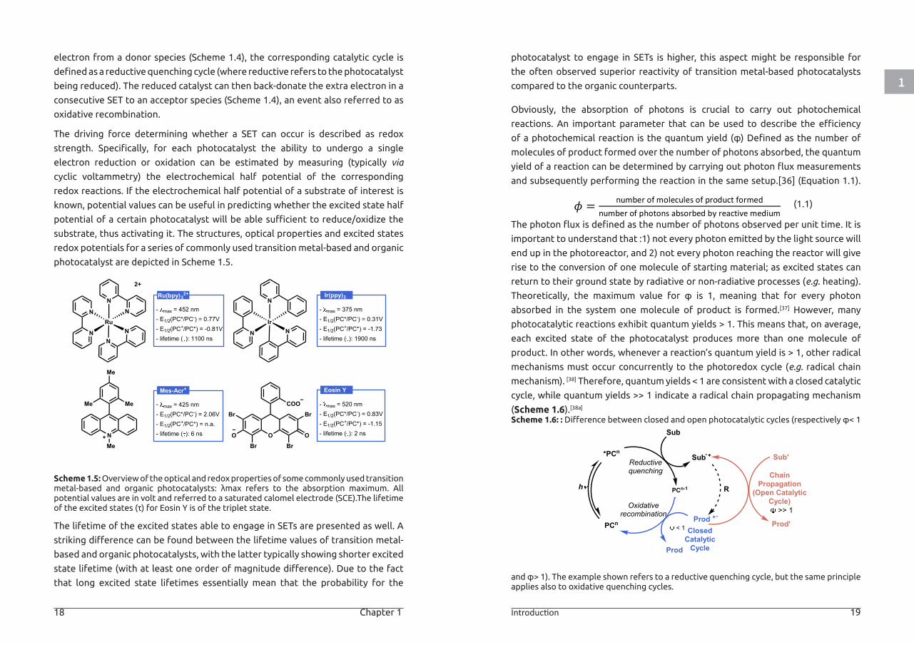
Scheme 1.5: Overview of the optical and redox properties of some commonly used transition metal-based and organic photocatalysts: λmax refers to the absorption maximum. All potential values are in volt and referred to a saturated calomel electrode (SCE).The lifetime of the excited states (τ) for Eosin Y is of the triplet state.
The lifetime of the excited states able to engage in SETs are presented as well. A
striking difference can be found between the lifetime values of transition metal-
based and organic photocatalysts, with the latter typically showing shorter excited
state lifetime (with at least one order of magnitude difference). Due to the fact
that long excited state lifetimes essentially mean that the probability for the
photocatalyst to engage in SETs is higher, this aspect might be responsible for
the often observed superior reactivity of transition metal-based photocatalysts
compared to the organic counterparts.
Obviously, the absorption of photons is crucial to carry out photochemical
reactions. An important parameter that can be used to describe the efficiency
of a photochemical reaction is the quantum yield (φ) Defined as the number of
molecules of product formed over the number of photons absorbed, the quantum
yield of a reaction can be determined by carrying out photon flux measurements
and subsequently performing the reaction in the same setup.[36] (Equation 1.1).
The photon flux is defined as the number of photons observed per unit time. It is
important to understand that :1) not every photon emitted by the light source will
end up in the photoreactor, and 2) not every photon reaching the reactor will give
rise to the conversion of one molecule of starting material; as excited states can
return to their ground state by radiative or non-radiative processes (e.g. heating).
Theoretically, the maximum value for φ is 1, meaning that for every photon
absorbed in the system one molecule of product is formed.[37] However, many
photocatalytic reactions exhibit quantum yields > 1. This means that, on average,
each excited state of the photocatalyst produces more than one molecule of
product. In other words, whenever a reaction’s quantum yield is > 1, other radical
mechanisms must occur concurrently to the photoredox cycle (e.g. radical chain
mechanism). [38] Therefore, quantum yields < 1 are consistent with a closed catalytic
cycle, while quantum yields >> 1 indicate a radical chain propagating mechanism
(Scheme 1.6).[38a]
Scheme 1.6: : Difference between closed and open photocatalytic cycles (respectively φ< 1
and φ> 1). The example shown refers to a reductive quenching cycle, but the same principle applies also to oxidative quenching cycles.
Ru(bpy)32+
- max = 452 nm- E1/2(PC*/PC-) = 0.77V- E1/2(PC+/PC*) = -0.81V- lifetime ( ): 1100 ns
N
N
RuN
N
N
N
N
IrN
N
2+
NMe
Me
MeMe
O
COO
Br
Br
OBr
O
Br
Ir(ppy)3
- max = 375 nm- E1/2(PC*/PC-) = 0.31V- E1/2(PC+/PC*) = -1.73- lifetime ( ): 1900 ns
Mes-Acr+
- max = 425 nm- E1/2(PC*/PC-) = 2.06V- E1/2(PC+/PC*) = n.a.- lifetime ( ): 6 ns
Eosin Y
- max = 520 nm- E1/2(PC*/PC-) = 0.83V- E1/2(PC+/PC*) = -1.15- lifetime ( ): 2 ns
𝜙𝜙𝜙𝜙 = number of molecules of product formednumber of photons absorbed by reactive medium
PCn
*PCn
PCn-1
Sub
Sub +
Prod +
Reductivequenching
Oxidativerecombination
h
Prod
Sub'
Prod'
ChainPropagation
(Open CatalyticCycle)
R
ClosedCatalyticCycle
< 1
>> 1
(1.1)
1
20 Chapter 1 Introduction 21
PHOTOREDOX CATALYSIS FOR BIOMOLECULE MODIFICATION
As mentioned earlier, compared to other catalytic approaches photoredox catalysis
offers the advantage of enabling the activation of organic substrates under mild
reaction conditions, while making use of visible-light irradiation as a sustainable
source of energy. Moreover, because of the inability of the majority of organic
substrates to absorb light in the visible spectrum, together with the fact that most
organic molecules possess an activation barrier that cannot be overcome at room
temperature, photoredox-based reactions typically exhibit high selectivities, with
little or no side products observed.[39]
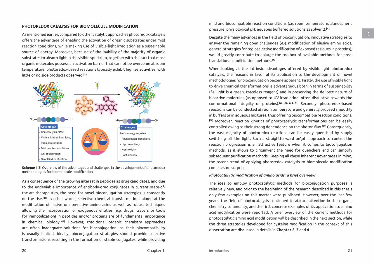
Scheme 1.7: Overview of the advantages and challenges in the development of photoredox methodologies for biomolecule modification.
As a consequence of the growing interest in peptides as drug candidates, and due
to the undeniable importance of antibody-drug conjugates in current state-of-
the-art therapeutics, the need for novel bioconjugation strategies is constantly
on the rise.[40] In other words, selective chemical transformations aimed at the
modification of native or non-native amino acids as well as robust techniques
allowing the incorporation of exogenous entities (e.g. drugs, tracers or tools
for immobilization) in peptides and/or proteins are of fundamental importance
in chemical biology.[41] However, traditional organic chemistry approaches
are often inadequate solutions for bioconjugation, as their biocompatibility
is usually limited. Ideally, bioconjugation strategies should provide selective
transformations resulting in the formation of stable conjugates, while providing
mild and biocompatible reaction conditions (i.e. room temperature, atmospheric
pressure, physiological pH, aqueous buffered solutions as solvent).[42]
Despite the many advances in the field of bioconjugation, innovative strategies to
answer the remaining open challenges (e.g. modification of elusive amino acids,
general strategies for regioselective modification of exposed residues in proteins),
would greatly contribute to enlarge the toolbox of available methods for post-
translational modification methods.[43]
When looking at the intrinsic advantages offered by visible-light photoredox
catalysis, the reasons in favor of its application to the development of novel
methodologies for bioconjugation become apparent. Firstly, the use of visible light
to drive chemical transformations is advantageous both in terms of sustainability
(i.e. light is a green, traceless reagent) and in preserving the delicate nature of
bioactive molecules (as opposed to UV irradiation, often disruptive towards the
conformational integrity of proteins).[2a, 3a, 33d, 44] Secondly, photoredox-based
reactions can be conducted at room temperature and generally proceed smoothly
in buffers or in aqueous mixtures, thus offering biocompatible reaction conditions.[3f] Moreover, reaction kinetics of photocatalytic transformations can be easily
controlled owing to their strong dependence on the photon flux.[45] Consequently,
the vast majority of photoredox reactions can be easily quenched by simply
switching off the light. Such a straightforward on\off approach to control the
reaction progression is an attractive feature when it comes to bioconjugation
methods, as it allows to circumvent the need for quenchers and can simplify
subsequent purification methods. Keeping all these inherent advantages in mind,
the recent trend of applying photoredox catalysis to biomolecule modification
comes as no surprise.
Photocatalytic modification of amino acids: a brief overview
The idea to employ photocatalytic methods for bioconjugation purposes is
relatively new, and prior to the beginning of the research described in this thesis
only few examples on this matter were published. However, over the last few
years, the field of photocatalysis continued to attract attention in the organic
chemistry community, and the first concrete examples of its application to amino
acid modification were reported. A brief overview of the current methods for
photocatalytic amino acid modification will be described in the next section, while
the three strategies developed for cysteine modification in the context of this
dissertation are discussed in details in Chapter 2, 3 and 4.
Methodology requires:
- Physiological conditions
- High selectivity
- Non-toxicity
- Fast kinetics
ChallengesPhotocatalysis offers:
- Visible light as harmless,
traceless reagent
- Mild reaction conditions
- On-off approach
- Simplified purification
Advantages
NIr
N
N
O
COO-
-O
Br
Br Br
O
Br
H2N OHH2N OH
1
22 Chapter 1 Introduction 23
Among the 20 proteinogenic amino acids, only few residues represent viable
targets for the development of successful bioconjugation methods. Typically,
bioconjugation methodologies rely on the intrinsic reactivity of the different
amino acids to achieve chemoselectivity (e.g. nucleophilicity/electrophilicity
or acid-base behavior). Alternatively, the accessibility of one specific residue in
proteins or peptides (i.e. position in the sequence or spatial orientation in the
overall structure) can be exploited to achieve site-selectivity in presence of other
reactive amino acids. A straightforward approach to classify methods for amino
acid modification is to organize them based on the targeted residue.
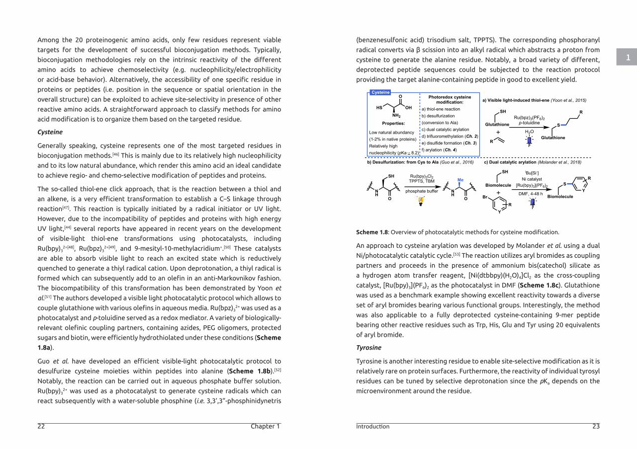
Cysteine
Generally speaking, cysteine represents one of the most targeted residues in
bioconjugation methods.[46] This is mainly due to its relatively high nucleophilicity
and to its low natural abundance, which render this amino acid an ideal candidate
to achieve regio- and chemo-selective modification of peptides and proteins.
The so-called thiol-ene click approach, that is the reaction between a thiol and
an alkene, is a very efficient transformation to establish a C–S linkage through
reaction[47]. This reaction is typically initiated by a radical initiator or UV light.
However, due to the incompatibility of peptides and proteins with high energy
UV light,[44] several reports have appeared in recent years on the development
of visible-light thiol-ene transformations using photocatalysts, including
Ru(bpy)32+[48], Ru(bpz)3
2+[49], and 9-mesityl-10-methylacridium+.[50] These catalysts
are able to absorb visible light to reach an excited state which is reductively
quenched to generate a thiyl radical cation. Upon deprotonation, a thiyl radical is
formed which can subsequently add to an olefin in an anti-Markovnikov fashion.
The biocompatibility of this transformation has been demonstrated by Yoon et
al.[51] The authors developed a visible light photocatalytic protocol which allows to
couple glutathione with various olefins in aqueous media. Ru(bpz)32+ was used as a
photocatalyst and p-toluidine served as a redox mediator. A variety of biologically-
relevant olefinic coupling partners, containing azides, PEG oligomers, protected
sugars and biotin, were efficiently hydrothiolated under these conditions (Scheme
1.8a).
Guo et al. have developed an efficient visible-light photocatalytic protocol to
desulfurize cysteine moieties within peptides into alanine (Scheme 1.8b).[52]
Notably, the reaction can be carried out in aqueous phosphate buffer solution.
Ru(bpy)32+ was used as a photocatalyst to generate cysteine radicals which can
react subsequently with a water-soluble phosphine (i.e. 3,3’,3”-phosphinidynetris
(benzenesulfonic acid) trisodium salt, TPPTS). The corresponding phosphoranyl
radical converts via β scission into an alkyl radical which abstracts a proton from
cysteine to generate the alanine residue. Notably, a broad variety of different,
deprotected peptide sequences could be subjected to the reaction protocol
providing the target alanine-containing peptide in good to excellent yield.
Scheme 1.8: Overview of photocatalytic methods for cysteine modification.
An approach to cysteine arylation was developed by Molander et al. using a dual
Ni/photocatalytic catalytic cycle.[53] The reaction utilizes aryl bromides as coupling
partners and proceeds in the presence of ammonium bis(catechol) silicate as
a hydrogen atom transfer reagent, [Ni(dtbbpy)(H2O)4]Cl2 as the cross-coupling
catalyst, [Ru(bpy)3](PF6)2 as the photocatalyst in DMF (Scheme 1.8c). Glutathione
was used as a benchmark example showing excellent reactivity towards a diverse
set of aryl bromides bearing various functional groups. Interestingly, the method
was also applicable to a fully deprotected cysteine-containing 9-mer peptide
bearing other reactive residues such as Trp, His, Glu and Tyr using 20 equivalents
of aryl bromide.
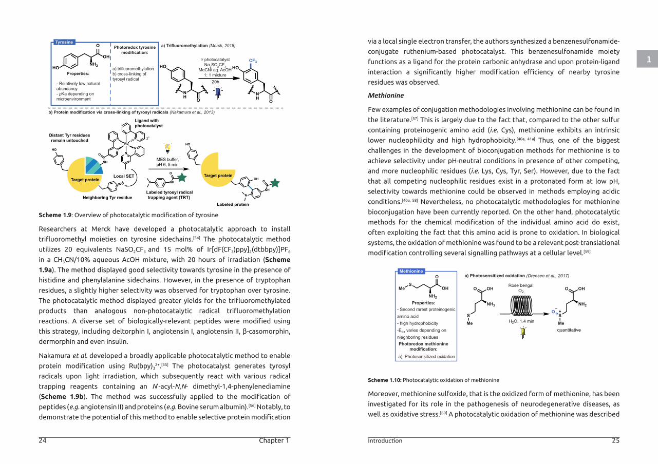
Tyrosine
Tyrosine is another interesting residue to enable site-selective modification as it is
relatively rare on protein surfaces. Furthermore, the reactivity of individual tyrosyl
residues can be tuned by selective deprotonation since the pKa depends on the
microenvironment around the residue.
Properties:
HS OH
O
NH2
Low natural abundancy(1-2% in native proteins)Relatively highnucleophilicity (pKa 8.2)
Photoredox cysteinemodification:
a) thiol-ene reactionb) desulfurization(conversion to Ala)c) dual catalytic arylationd) trifluoromethylation (Ch. 2)e) disulfide formation (Ch. 3)f) arylation (Ch. 4)
Cysteine
b) Desulfurization: from Cys to Ala (Guo et al., 2016)
phosphate buffer
Ru(bpy)3Cl2TPPTS, TBM
NH
O
SH
NH
Me
O
c) Dual catalytic arylation (Molander et al., 2018)
a) Visible light-induced thiol-ene (Yoon et al., 2015)
DMF, 4-48 h
iBu[Si-]Ni catalyst
[Ru(bpy)3](PF6)2Biomolecule
Y
Br
R
Biomolecule
SY
R
R
Ru(bpz)3(PF6)2p-toluidineGlutathione
Glutathione
SH2O
SH
SH
R
1
24 Chapter 1 Introduction 25
Scheme 1.9: Overview of photocatalytic modification of tyrosine
Researchers at Merck have developed a photocatalytic approach to install
trifluoromethyl moieties on tyrosine sidechains.[54] The photocatalytic method
utilizes 20 equivalents NaSO2CF3 and 15 mol% of Ir[dF(CF3)ppy]2(dtbbpy)]PF6
in a CH3CN/10% aqueous AcOH mixture, with 20 hours of irradiation (Scheme
1.9a). The method displayed good selectivity towards tyrosine in the presence of
histidine and phenylalanine sidechains. However, in the presence of tryptophan
residues, a slightly higher selectivity was observed for tryptophan over tyrosine.
The photocatalytic method displayed greater yields for the trifluoromethylated
products than analogous non-photocatalytic radical trifluoromethylation
reactions. A diverse set of biologically-relevant peptides were modified using
this strategy, including deltorphin I, angiotensin I, angiotensin II, β-casomorphin,
dermorphin and even insulin.
Nakamura et al. developed a broadly applicable photocatalytic method to enable
protein modification using Ru(bpy)32+.[55] The photocatalyst generates tyrosyl
radicals upon light irradiation, which subsequently react with various radical
trapping reagents containing an N’-acyl-N,N- dimethyl-1,4-phenylenediamine
(Scheme 1.9b). The method was successfully applied to the modification of
peptides (e.g. angiotensin II) and proteins (e.g. Bovine serum albumin).[56] Notably, to
demonstrate the potential of this method to enable selective protein modification
via a local single electron transfer, the authors synthesized a benzenesulfonamide-
conjugate ruthenium-based photocatalyst. This benzenesulfonamide moiety
functions as a ligand for the protein carbonic anhydrase and upon protein-ligand
interaction a significantly higher modification efficiency of nearby tyrosine
residues was observed.
Methionine
Few examples of conjugation methodologies involving methionine can be found in
the literature.[57] This is largely due to the fact that, compared to the other sulfur
containing proteinogenic amino acid (i.e. Cys), methionine exhibits an intrinsic
lower nucleophilicity and high hydrophobicity.[40a, 41a] Thus, one of the biggest
challenges in the development of bioconjugation methods for methionine is to
achieve selectivity under pH-neutral conditions in presence of other competing,
and more nucleophilic residues (i.e. Lys, Cys, Tyr, Ser). However, due to the fact
that all competing nucleophilic residues exist in a protonated form at low pH,
selectivity towards methionine could be observed in methods employing acidic
conditions.[40a, 58] Nevertheless, no photocatalytic methodologies for methionine
bioconjugation have been currently reported. On the other hand, photocatalytic
methods for the chemical modification of the individual amino acid do exist,
often exploiting the fact that this amino acid is prone to oxidation. In biological
systems, the oxidation of methionine was found to be a relevant post-translational
modification controlling several signalling pathways at a cellular level.[59]
Scheme 1.10: Photocatalytic oxidation of methionine
Moreover, methionine sulfoxide, that is the oxidized form of methionine, has been
investigated for its role in the pathogenesis of neurodegenerative diseases, as
well as oxidative stress.[60] A photocatalytic oxidation of methionine was described
N
NRu
NN
NN
O
NH
2+
Ligand withphotocatalyst
Target proteinO
Neighboring Tyr residue
Local SETN NH
O
Labeled tyrosyl radicaltrapping agent (TRT)
MES buffer,pH 6, 5 min
HO
Distant Tyr residuesremain untouched
Target protein
HO
OH
NH
O
N
Labeled protein
OH
O
NH2HO
20h
NH
ONH
O
HO HOCF3
a) trifluoromethylationb) cross-linking of tyrosyl radical
Properties:
- Relatively low naturalabundancy- pKa depending onmicroenvironment
Ir photocatalystNa2SO2CF3
MeCN/ aq. AcOH1: 1 mixture
a) Trifluoromethylation (Merck, 2018)
b) Protein modification via cross-linking of tyrosyl radicals (Nakamura et al., 2013)
TyrosinePhotoredox tyrosine
modification:
Properties:
Photoredox methioninemodification:
Methioninea) Photosensitized oxidation (Dreesen et al., 2017)
OH
O
NH2
- Second rarest proteinogenicamino acid- high hydrophobicity-Eox varies depending onnieghboring residues
a) Photosensitized oxidation
SMe Rose bengal,
O2,
quantitative
H2O, 1.4 min
OHO
NH2
SMe
OHO
NH2
SMe
O
1
26 Chapter 1 Introduction 27
by Dreesen, Heinrichs, Monbaliu and co-workers (Scheme 1.10).[61] In this scalable
continuous-flow protocol, the oxidation of methionine via the formation of singlet
oxygen was obtained with rose Bengal as photosensitizer. The biphasic reaction
(i.e. liquid reagent and molecular oxygen) was performed in a glass mesoscale
commercially available photoreactor and afforded quantitative yields within 1.4
minutes of reaction time and a productivity up to 132 g/day.
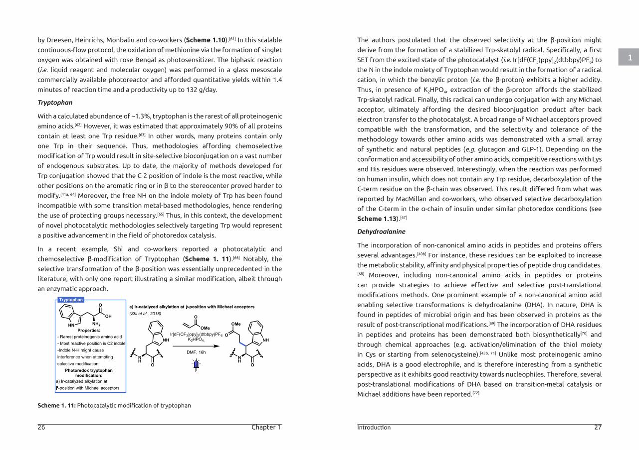
Tryptophan
With a calculated abundance of ~1.3%, tryptophan is the rarest of all proteinogenic
amino acids.[62] However, it was estimated that approximately 90% of all proteins
contain at least one Trp residue.[63] In other words, many proteins contain only
one Trp in their sequence. Thus, methodologies affording chemoselective
modification of Trp would result in site-selective bioconjugation on a vast number
of endogenous substrates. Up to date, the majority of methods developed for
Trp conjugation showed that the C-2 position of indole is the most reactive, while
other positions on the aromatic ring or in β to the stereocenter proved harder to
modify.[41a, 64] Moreover, the free NH on the indole moiety of Trp has been found
incompatible with some transition metal-based methodologies, hence rendering
the use of protecting groups necessary.[65] Thus, in this context, the development
of novel photocatalytic methodologies selectively targeting Trp would represent
a positive advancement in the field of photoredox catalysis.
In a recent example, Shi and co-workers reported a photocatalytic and
chemoselective β-modification of Tryptophan (Scheme 1. 11).[66] Notably, the
selective transformation of the β-position was essentially unprecedented in the
literature, with only one report illustrating a similar modification, albeit through
an enzymatic approach.
Scheme 1. 11: Photocatalytic modification of tryptophan
The authors postulated that the observed selectivity at the β-position might
derive from the formation of a stabilized Trp-skatolyl radical. Specifically, a first
SET from the excited state of the photocatalyst (i.e. Ir[dF(CF3)ppy]2(dtbbpy)PF6) to
the N in the indole moiety of Tryptophan would result in the formation of a radical
cation, in which the benzylic proton (i.e. the β-proton) exhibits a higher acidity.
Thus, in presence of K2HPO4, extraction of the β-proton affords the stabilized
Trp-skatolyl radical. Finally, this radical can undergo conjugation with any Michael
acceptor, ultimately affording the desired bioconjugation product after back
electron transfer to the photocatalyst. A broad range of Michael acceptors proved
compatible with the transformation, and the selectivity and tolerance of the
methodology towards other amino acids was demonstrated with a small array
of synthetic and natural peptides (e.g. glucagon and GLP-1). Depending on the
conformation and accessibility of other amino acids, competitive reactions with Lys
and His residues were observed. Interestingly, when the reaction was performed
on human insulin, which does not contain any Trp residue, decarboxylation of the
C-term residue on the β-chain was observed. This result differed from what was
reported by MacMillan and co-workers, who observed selective decarboxylation
of the C-term in the α-chain of insulin under similar photoredox conditions (see
Scheme 1.13).[67]
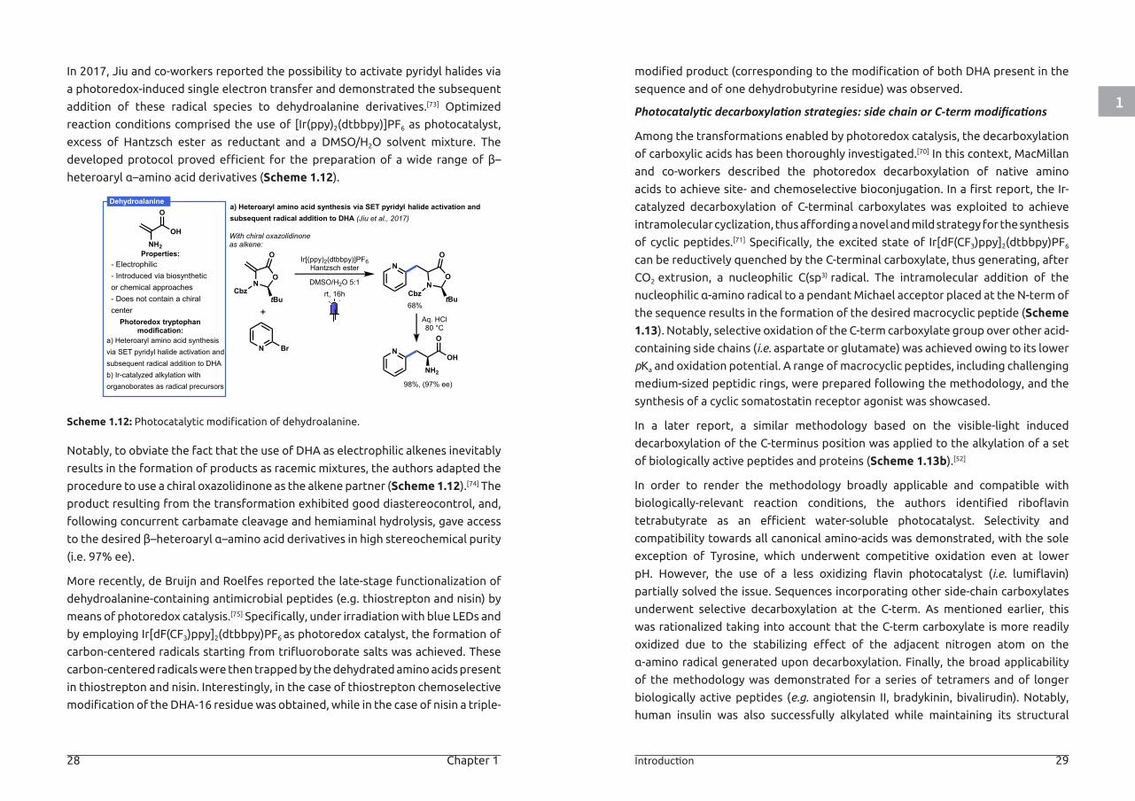
Dehydroalanine
The incorporation of non-canonical amino acids in peptides and proteins offers
several advantages.[40b] For instance, these residues can be exploited to increase
the metabolic stability, affinity and physical properties of peptide drug candidates.[68] Moreover, including non-canonical amino acids in peptides or proteins
can provide strategies to achieve effective and selective post-translational
modifications methods. One prominent example of a non-canonical amino acid
enabling selective transformations is dehydroalanine (DHA). In nature, DHA is
found in peptides of microbial origin and has been observed in proteins as the
result of post-transcriptional modifications.[69] The incorporation of DHA residues
in peptides and proteins has been demonstrated both biosynthetically[70] and
through chemical approaches (e.g. activation/elimination of the thiol moiety
in Cys or starting from selenocysteine).[43b, 71] Unlike most proteinogenic amino
acids, DHA is a good electrophile, and is therefore interesting from a synthetic
perspective as it exhibits good reactivity towards nucleophiles. Therefore, several
post-translational modifications of DHA based on transition-metal catalysis or
Michael additions have been reported.[72]
Properties:
Photoredox tryptophanmodification:
Tryptophana) Ir-catalyzed alkylation at -position with Michael acceptors(Shi et al., 2018)
- Rarest proteinogenic amino acid- Most reactive position is C2 indole-Indole N-H might causeinterference when attemptingselective modification
a) Ir-catalyzed alkylation at-position with Michael acceptors
OH
O
NH2HN
Ir[dF(CF3)ppy]2(dtbbpy)PF6K2HPO4,
NH
O
NH
DMF, 16hNH
O
NH
OMe
O
O
OMe
1
28 Chapter 1 Introduction 29
In 2017, Jiu and co-workers reported the possibility to activate pyridyl halides via
a photoredox-induced single electron transfer and demonstrated the subsequent
addition of these radical species to dehydroalanine derivatives.[73] Optimized
reaction conditions comprised the use of [Ir(ppy)2(dtbbpy)]PF6 as photocatalyst,
excess of Hantzsch ester as reductant and a DMSO/H2O solvent mixture. The
developed protocol proved efficient for the preparation of a wide range of β–
heteroaryl α–amino acid derivatives (Scheme 1.12).
Scheme 1.12: Photocatalytic modification of dehydroalanine.
Notably, to obviate the fact that the use of DHA as electrophilic alkenes inevitably
results in the formation of products as racemic mixtures, the authors adapted the
procedure to use a chiral oxazolidinone as the alkene partner (Scheme 1.12).[74] The
product resulting from the transformation exhibited good diastereocontrol, and,
following concurrent carbamate cleavage and hemiaminal hydrolysis, gave access
to the desired β–heteroaryl α–amino acid derivatives in high stereochemical purity
(i.e. 97% ee).
More recently, de Bruijn and Roelfes reported the late-stage functionalization of
dehydroalanine-containing antimicrobial peptides (e.g. thiostrepton and nisin) by
means of photoredox catalysis.[75] Specifically, under irradiation with blue LEDs and
by employing Ir[dF(CF3)ppy]2(dtbbpy)PF6 as photoredox catalyst, the formation of
carbon-centered radicals starting from trifluoroborate salts was achieved. These
carbon-centered radicals were then trapped by the dehydrated amino acids present
in thiostrepton and nisin. Interestingly, in the case of thiostrepton chemoselective
modification of the DHA-16 residue was obtained, while in the case of nisin a triple-
modified product (corresponding to the modification of both DHA present in the
sequence and of one dehydrobutyrine residue) was observed.
Photocatalytic decarboxylation strategies: side chain or C-term modifications
Among the transformations enabled by photoredox catalysis, the decarboxylation
of carboxylic acids has been thoroughly investigated.[70] In this context, MacMillan
and co-workers described the photoredox decarboxylation of native amino
acids to achieve site- and chemoselective bioconjugation. In a first report, the Ir-
catalyzed decarboxylation of C-terminal carboxylates was exploited to achieve
intramolecular cyclization, thus affording a novel and mild strategy for the synthesis
of cyclic peptides.[71] Specifically, the excited state of Ir[dF(CF3)ppy]2(dtbbpy)PF6
can be reductively quenched by the C-terminal carboxylate, thus generating, after
CO2 extrusion, a nucleophilic C(sp3) radical. The intramolecular addition of the
nucleophilic α-amino radical to a pendant Michael acceptor placed at the N-term of
the sequence results in the formation of the desired macrocyclic peptide (Scheme
1.13). Notably, selective oxidation of the C-term carboxylate group over other acid-
containing side chains (i.e. aspartate or glutamate) was achieved owing to its lower
pKa and oxidation potential. A range of macrocyclic peptides, including challenging
medium-sized peptidic rings, were prepared following the methodology, and the
synthesis of a cyclic somatostatin receptor agonist was showcased.
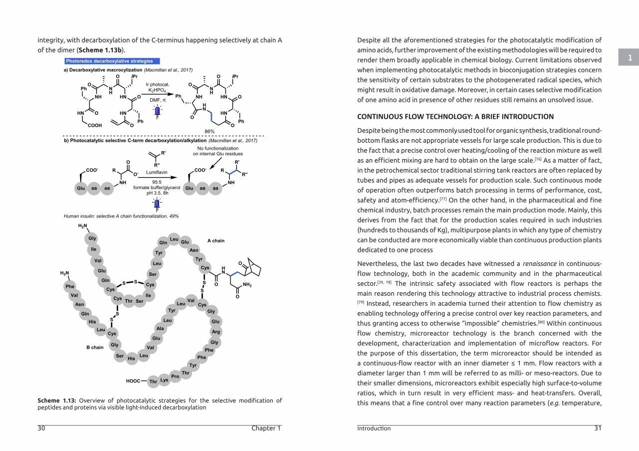
In a later report, a similar methodology based on the visible-light induced
decarboxylation of the C-terminus position was applied to the alkylation of a set
of biologically active peptides and proteins (Scheme 1.13b).[52]
In order to render the methodology broadly applicable and compatible with
biologically-relevant reaction conditions, the authors identified riboflavin
tetrabutyrate as an efficient water-soluble photocatalyst. Selectivity and
compatibility towards all canonical amino-acids was demonstrated, with the sole
exception of Tyrosine, which underwent competitive oxidation even at lower
pH. However, the use of a less oxidizing flavin photocatalyst (i.e. lumiflavin)
partially solved the issue. Sequences incorporating other side-chain carboxylates
underwent selective decarboxylation at the C-term. As mentioned earlier, this
was rationalized taking into account that the C-term carboxylate is more readily
oxidized due to the stabilizing effect of the adjacent nitrogen atom on the
α-amino radical generated upon decarboxylation. Finally, the broad applicability
of the methodology was demonstrated for a series of tetramers and of longer
biologically active peptides (e.g. angiotensin II, bradykinin, bivalirudin). Notably,
human insulin was also successfully alkylated while maintaining its structural
Properties:
Photoredox tryptophanmodification:
Dehydroalaninea) Heteroaryl amino acid synthesis via SET pyridyl halide activation andsubsequent radical addition to DHA (Jiu et al., 2017)
- Electrophilic- Introduced via biosyntheticor chemical approaches- Does not contain a chiralcenter
a) Heteroaryl amino acid synthesisvia SET pyridyl halide activation andsubsequent radical addition to DHAb) Ir-catalyzed alkylation withorganoborates as radical precursors
OH
O
NH2
N
NO
tBu
O
CbzN
O
O
tBuCbz
With chiral oxazolidinoneas alkene:
68%
N
98%, (97% ee)
NH2
OH
O
Aq. HCl80 °C
Ir[(ppy)2(dtbbpy)]PF6Hantzsch ester
DMSO/H2O 5:1rt, 16h
N Br
1
30 Chapter 1 Introduction 31
integrity, with decarboxylation of the C-terminus happening selectively at chain A
of the dimer (Scheme 1.13b).
Scheme 1.13: Overview of photocatalytic strategies for the selective modification of peptides and proteins via visible light-induced decarboxylation
Despite all the aforementioned strategies for the photocatalytic modification of
amino acids, further improvement of the existing methodologies will be required to
render them broadly applicable in chemical biology. Current limitations observed
when implementing photocatalytic methods in bioconjugation strategies concern
the sensitivity of certain substrates to the photogenerated radical species, which
might result in oxidative damage. Moreover, in certain cases selective modification
of one amino acid in presence of other residues still remains an unsolved issue.
CONTINUOUS FLOW TECHNOLOGY: A BRIEF INTRODUCTION
Despite being the most commonly used tool for organic synthesis, traditional round-
bottom flasks are not appropriate vessels for large scale production. This is due to
the fact that a precise control over heating/cooling of the reaction mixture as well
as an efficient mixing are hard to obtain on the large scale.[76] As a matter of fact,
in the petrochemical sector traditional stirring tank reactors are often replaced by
tubes and pipes as adequate vessels for production scale. Such continuous mode
of operation often outperforms batch processing in terms of performance, cost,
safety and atom-efficiency.[77] On the other hand, in the pharmaceutical and fine
chemical industry, batch processes remain the main production mode. Mainly, this
derives from the fact that for the production scales required in such industries
(hundreds to thousands of Kg), multipurpose plants in which any type of chemistry
can be conducted are more economically viable than continuous production plants
dedicated to one process
Nevertheless, the last two decades have witnessed a renaissance in continuous-
flow technology, both in the academic community and in the pharmaceutical
sector.[39, 78] The intrinsic safety associated with flow reactors is perhaps the
main reason rendering this technology attractive to industrial process chemists.[79] Instead, researchers in academia turned their attention to flow chemistry as
enabling technology offering a precise control over key reaction parameters, and
thus granting access to otherwise “impossible” chemistries.[80] Within continuous
flow chemistry, microreactor technology is the branch concerned with the
development, characterization and implementation of microflow reactors. For
the purpose of this dissertation, the term microreactor should be intended as
a continuous-flow reactor with an inner diameter ≤ 1 mm. Flow reactors with a
diameter larger than 1 mm will be referred to as milli- or meso-reactors. Due to
their smaller dimensions, microreactors exhibit especially high surface-to-volume
ratios, which in turn result in very efficient mass- and heat-transfers. Overall,
this means that a fine control over many reaction parameters (e.g. temperature,
Photoredox decarboxylative strategies
a) Decarboxylative macrocylization (Macmillan et al., 2017)
Ir photocat.K2HPO4,
NHPhO
NH
O
HN
iPr
O
HNPh
O
OHN
COOH
NHPh
ONH
O
HN
iPr
O
HNPh
OO
HN
DMF, rt
86%
95:5formate buffer/glycerol
pH 3.5, 8h
Lumiflavin
aa
COO-
Glu aaNH
RO
O-
aa
COO-
Glu aaNH
RR'
R''
No functionalizationon internal Glu residuesR'
R''
Cys
Cys Thr Ser
Gly
Ile
Val
Glu
Gln
Ile
CysS SSer
Leu
Tyr
GlnLeu Glu
Asn
Tyr
Cys HN
O
O
O
NH2SS
CysValLeu
Gly
Glu
Arg
GlyPhe
PheTyr
ThrPro
LysThrHOOC
SS
Tyr
LeuAla
GluCys
ValLeuHisSer
Gly
LeuHis
Gln
Asn
Val
Phe
H2N
H2N
Human insulin: selective A chain functionalization, 49%
A chain
B chain
b) Photocatalytic selective C-term decarboxylation/alkylation (Macmillan et al., 2017)
1
32 Chapter 1 Introduction 33
pressure, mixing etc.) is straightforward in microreactors. From a safety point
of view, the accumulation of significant quantities of hazardous materials or
reaction intermediates is prevented due to the small volumes of microreactors.
Moreover, the scaling-up of continuous flow microreactors can be regarded a
rather straightforward procedure, often requiring only a minimal redesign of the
reactor/reaction conditions. Other advantages of microreactors are the improved
mixing, ease of processing multiphase reaction mixtures and potential to include
inline analytical technologies, allowing to develop fully automated and/or self-
optimizing processes. Specifically, inline spectroscopic tools, self-optimization
protocols and automation allow to further reduce human interaction (see Chapter
7).[81]
CONTINUOUS FLOW PHOTOCHEMISTRY
Over the last decade, the renewed interest for photocatalysis in organic synthesis
also brought some old and unsolved problems back to the surface. The majority of
the issues associated with the use of light to promote chemical transformations
derive from the complexity of photochemical processes. However, the main
practical issue preventing the widespread use of photochemical transformations in
the chemical industry is that scalability is hampered. This is due to the attenuation
effect of photon transport described by the Bouguer−Lambert−Beer law, which
prevents the use of a dimension-enlarging strategy for scale-up. If larger reactors
are used, over-irradiation of the reaction mixture can become an important issue as
the reaction times are substantially increased. This often results in the formation
of byproducts, complicating the purification process significantly.
Thus, the use of continuous-flow microreactors for photochemical applications
has received a lot of attention as it allows to overcome the issues associated with
batch photochemistry. The narrow channels of a typical microreactor provide the
means to ensure a uniform irradiation of the entire reaction mixture. Consequently,
photochemical reactions can be substantially accelerated (from hours/days in batch
to seconds/mins in flow) and lower photocatalyst loadings are often feasible. This
reduction in reaction time minimizes potential byproduct formation and increases
the productivity of the photochemical process.
PHOTOREDOX CATALYSIS IN CONTINUOUS FLOW: FUNDAMENTALS
In the following section, the fundamental aspects that render continuous flow
technology an ideal platform to carry out photochemical transformations will be
discussed in details, with an emphasis on the most relevant principles pertinent to
the research work described herein.
Good reasons why to “go with the flow”:
1. Improved irradiation of the reaction mixture
Photochemical reactions are driven by the absorption of photons. Consequently, a
homogeneous energy distribution inside the photoreactor is crucial to obtain high
yields and high selectivities. According to the well-known Bouguer-Lambert-Beer
law (Equation 1.2), the radiation distribution will not be uniform in a reactor due
to absorption effects.
(1.2)
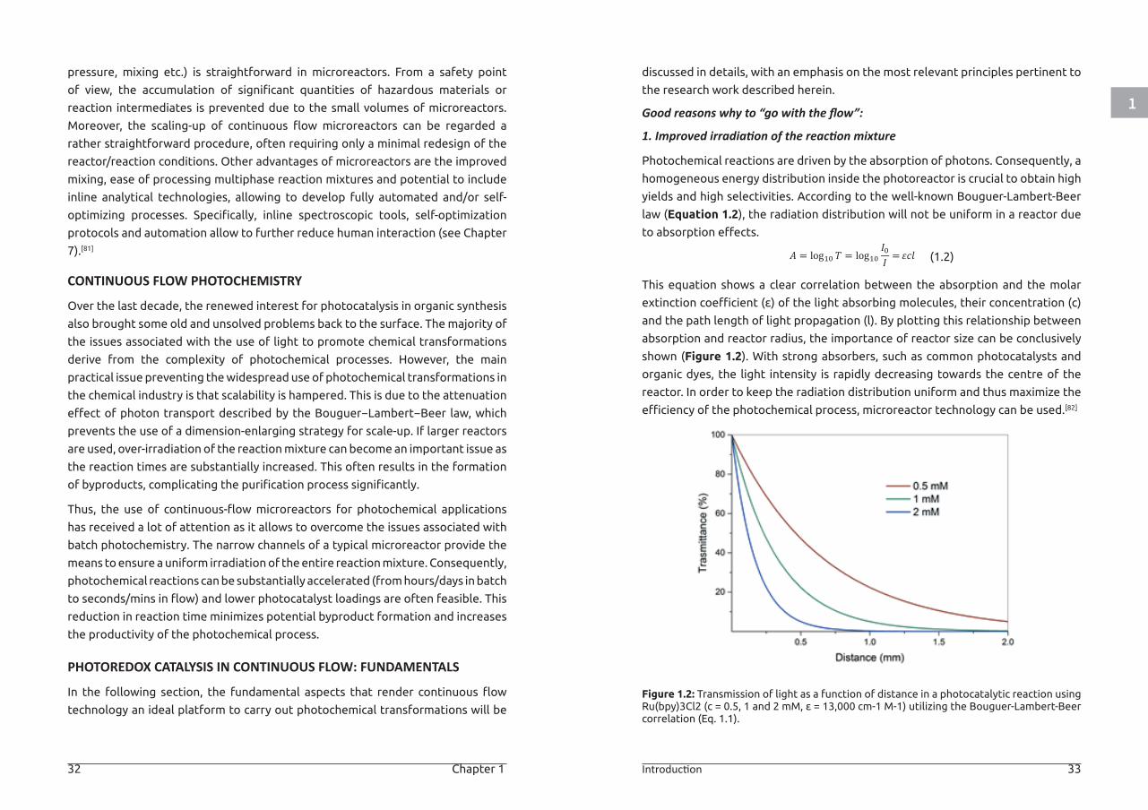
This equation shows a clear correlation between the absorption and the molar
extinction coefficient (ε) of the light absorbing molecules, their concentration (c)
and the path length of light propagation (l). By plotting this relationship between
absorption and reactor radius, the importance of reactor size can be conclusively
shown (Figure 1.2). With strong absorbers, such as common photocatalysts and
organic dyes, the light intensity is rapidly decreasing towards the centre of the
reactor. In order to keep the radiation distribution uniform and thus maximize the
efficiency of the photochemical process, microreactor technology can be used.[82]
Figure 1.2: Transmission of light as a function of distance in a photocatalytic reaction using Ru(bpy)3Cl2 (c = 0.5, 1 and 2 mM, ε = 13,000 cm-1 M-1) utilizing the Bouguer-Lambert-Beer correlation (Eq. 1.1).
𝐴𝐴𝐴𝐴 = log10 𝑇𝑇𝑇𝑇 = log10𝐼𝐼𝐼𝐼0𝐼𝐼𝐼𝐼
= 𝜀𝜀𝜀𝜀𝜀𝜀𝜀𝜀𝜀𝜀𝜀𝜀
1
34 Chapter 1 Introduction 35
2. Improved reaction selectivity and increased reproducibility.
One of the key aspects in any chemical reaction is the product selectivity. It is
generally accepted that microreactors provide opportunities to increase the
reaction selectivity substantially. This is often attributed to the enhanced mass-,
heat- and photon-transport phenomena observed in microchannels, which offers a
high reproducibility of the reaction conditions. Such benefits can be related to the
increased surface-to-volume ratio in microchannels.
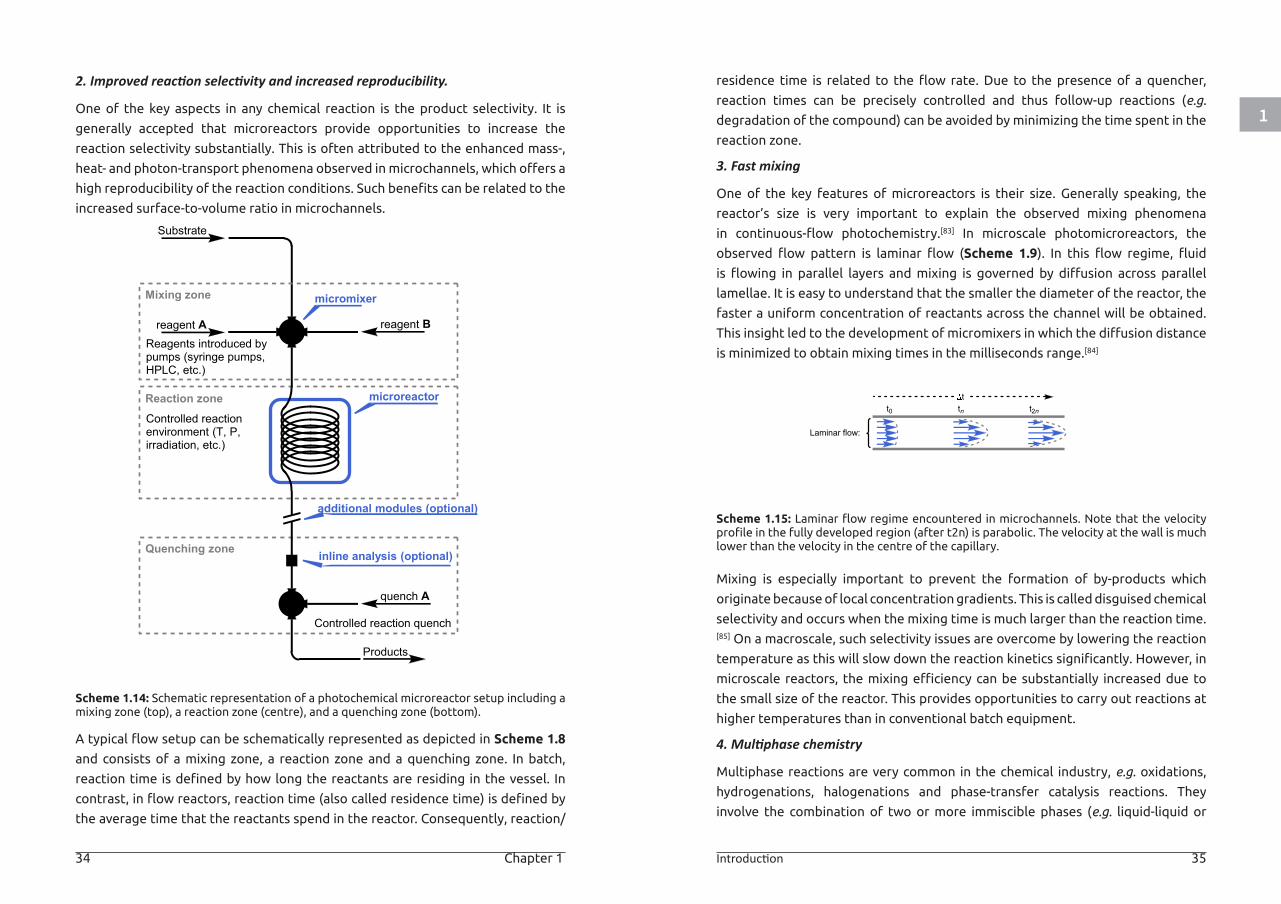
Scheme 1.14: Schematic representation of a photochemical microreactor setup including a mixing zone (top), a reaction zone (centre), and a quenching zone (bottom).
A typical flow setup can be schematically represented as depicted in Scheme 1.8
and consists of a mixing zone, a reaction zone and a quenching zone. In batch,
reaction time is defined by how long the reactants are residing in the vessel. In
contrast, in flow reactors, reaction time (also called residence time) is defined by
the average time that the reactants spend in the reactor. Consequently, reaction/
residence time is related to the flow rate. Due to the presence of a quencher,
reaction times can be precisely controlled and thus follow-up reactions (e.g.
degradation of the compound) can be avoided by minimizing the time spent in the
reaction zone.
3. Fast mixing
One of the key features of microreactors is their size. Generally speaking, the
reactor’s size is very important to explain the observed mixing phenomena
in continuous-flow photochemistry.[83] In microscale photomicroreactors, the
observed flow pattern is laminar flow (Scheme 1.9). In this flow regime, fluid
is flowing in parallel layers and mixing is governed by diffusion across parallel
lamellae. It is easy to understand that the smaller the diameter of the reactor, the
faster a uniform concentration of reactants across the channel will be obtained.
This insight led to the development of micromixers in which the diffusion distance
is minimized to obtain mixing times in the milliseconds range.[84]
Scheme 1.15: Laminar flow regime encountered in microchannels. Note that the velocity profile in the fully developed region (after t2n) is parabolic. The velocity at the wall is much lower than the velocity in the centre of the capillary.
Mixing is especially important to prevent the formation of by-products which
originate because of local concentration gradients. This is called disguised chemical
selectivity and occurs when the mixing time is much larger than the reaction time.[85] On a macroscale, such selectivity issues are overcome by lowering the reaction
temperature as this will slow down the reaction kinetics significantly. However, in
microscale reactors, the mixing efficiency can be substantially increased due to
the small size of the reactor. This provides opportunities to carry out reactions at
higher temperatures than in conventional batch equipment.
4. Multiphase chemistry
Multiphase reactions are very common in the chemical industry, e.g. oxidations,
hydrogenations, halogenations and phase-transfer catalysis reactions. They
involve the combination of two or more immiscible phases (e.g. liquid-liquid or
Reaction zone
Mixing zone
reagent A
Substrate
reagent B
Controlled reactionenvironment (T, P,irradiation, etc.)
micromixer
Reagents introduced bypumps (syringe pumps,HPLC, etc.)
Quenching zone
microreactor
additional modules (optional)
quench A
inline analysis (optional)
Controlled reaction quench
Products
Laminar flow:
tt0 tn t2n
1
36 Chapter 1 Introduction 37
gas-liquid reactions). When mass transfer from one phase to the other is the rate-
determining step, it is crucial to maximize the interfacial area between the phases.
In batch, the interfacial area is low and poorly defined, which leads to prolonged
reaction times. Due to the small characteristic dimensions of microreactors, large
and well-defined interfacial areas are observed, which can reach up to 9000 m2·m-
3. These large interfacial areas lead to efficient mass transfer between the two
phases. More specifically, the mass transfer between two phases can be described
with the overall volumetric mass transfer coefficient (kLa), which in microreactors
is one to two orders of magnitude higher than for classical multiphase reactors.
Several microreactor designs have been developed to carry out multiphase
reaction conditions (Scheme 1.10).[86]
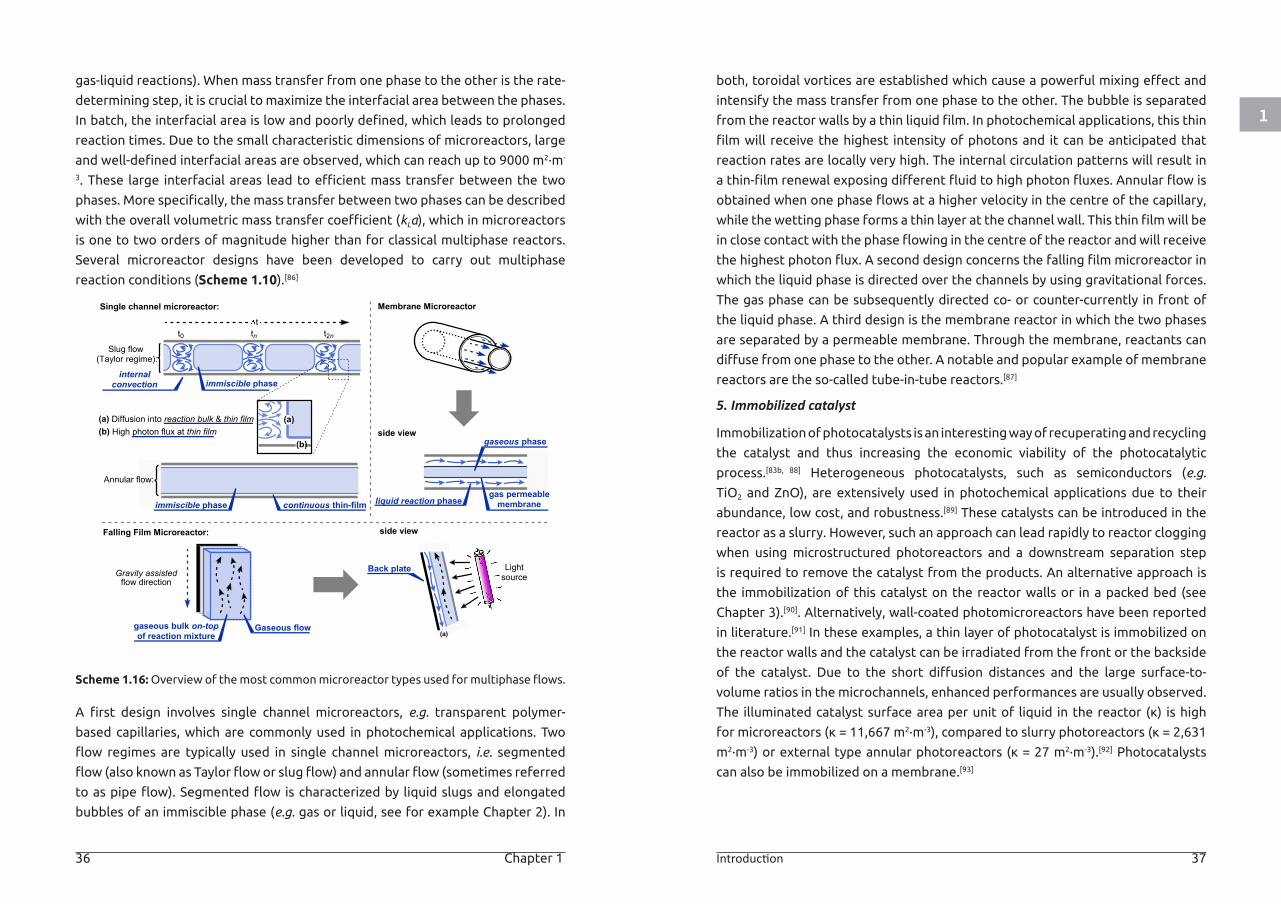
Scheme 1.16: Overview of the most common microreactor types used for multiphase flows.
A first design involves single channel microreactors, e.g. transparent polymer-
based capillaries, which are commonly used in photochemical applications. Two
flow regimes are typically used in single channel microreactors, i.e. segmented
flow (also known as Taylor flow or slug flow) and annular flow (sometimes referred
to as pipe flow). Segmented flow is characterized by liquid slugs and elongated
bubbles of an immiscible phase (e.g. gas or liquid, see for example Chapter 2). In
both, toroidal vortices are established which cause a powerful mixing effect and
intensify the mass transfer from one phase to the other. The bubble is separated
from the reactor walls by a thin liquid film. In photochemical applications, this thin
film will receive the highest intensity of photons and it can be anticipated that
reaction rates are locally very high. The internal circulation patterns will result in
a thin-film renewal exposing different fluid to high photon fluxes. Annular flow is
obtained when one phase flows at a higher velocity in the centre of the capillary,
while the wetting phase forms a thin layer at the channel wall. This thin film will be
in close contact with the phase flowing in the centre of the reactor and will receive
the highest photon flux. A second design concerns the falling film microreactor in
which the liquid phase is directed over the channels by using gravitational forces.
The gas phase can be subsequently directed co- or counter-currently in front of
the liquid phase. A third design is the membrane reactor in which the two phases
are separated by a permeable membrane. Through the membrane, reactants can
diffuse from one phase to the other. A notable and popular example of membrane
reactors are the so-called tube-in-tube reactors.[87]
5. Immobilized catalyst
Immobilization of photocatalysts is an interesting way of recuperating and recycling
the catalyst and thus increasing the economic viability of the photocatalytic
process.[83b, 88] Heterogeneous photocatalysts, such as semiconductors (e.g.
TiO2 and ZnO), are extensively used in photochemical applications due to their
abundance, low cost, and robustness.[89] These catalysts can be introduced in the
reactor as a slurry. However, such an approach can lead rapidly to reactor clogging
when using microstructured photoreactors and a downstream separation step
is required to remove the catalyst from the products. An alternative approach is
the immobilization of this catalyst on the reactor walls or in a packed bed (see
Chapter 3).[90]. Alternatively, wall-coated photomicroreactors have been reported
in literature.[91] In these examples, a thin layer of photocatalyst is immobilized on
the reactor walls and the catalyst can be irradiated from the front or the backside
of the catalyst. Due to the short diffusion distances and the large surface-to-
volume ratios in the microchannels, enhanced performances are usually observed.
The illuminated catalyst surface area per unit of liquid in the reactor (κ) is high
for microreactors (κ = 11,667 m2·m-3), compared to slurry photoreactors (κ = 2,631
m2·m-3) or external type annular photoreactors (κ = 27 m2·m-3).[92] Photocatalysts
can also be immobilized on a membrane.[93]
Slug flow(Taylor regime):
tt0 tn t2n
immiscible phaseinternal
convection
(a) Diffusion into reaction bulk & thin film(b) High photon flux at thin film
(b)
(a)
Annular flow:
immiscible phase continuous thin-film
side view
LightsourceGravity assisted
flow direction
Gaseous flow
Back plate
gaseous bulk on-topof reaction mixture
Falling Film Microreactor:
Membrane Microreactor
liquid reaction phasegas permeablemembrane
side viewgaseous phase
(a)
Single channel microreactor:
1
38 Chapter 1 Introduction 39
6. Increased safety of operation
Increasing the operational safety of hazardous reactions is one of the main
arguments for the chemical industry to switch to a continuous-flow protocol.
Microreactors have small dimensions which reduces the total inventory of
hazardous chemicals and thus avoids any safety risks associated with its handling.
Furthermore, the impact of an explosion is directly related to the total amount
of explosive materials present in the reactor to the power of 1/3. Despite the
advantages of microreactors, one must still be careful as explosions can propagate
into the neighbouring storage vessels which might contain larger amounts of
explosive material.[94] This also demonstrates the need of suitable quenchers
at the reactor outlet, which can prevent explosion propagation. Due to the
increased safety, reaction conditions which are impossible to carry out in batch
can be accessible in flow microreactors. This is especially true for photochemical
reactions involving gases (see Chapter 2) or potentially hazardous intermediates
(e.g. diazonium salts, see Chapter 4).
7. Other reasons
Besides the aforementioned reasons, other advantages inherent to continuous-flow
technology might be beneficial when carrying out photochemical transformations.
However, as these advantages are not directly correlated with the experimental
work presented in this dissertation, they will only be briefly described herein.
Due to their high surface-to-volume ratio, microreactors provide an efficient
heat dissipation.[80a] This feature is especially relevant in the case of highly
exothermic reactions or to dissipate the heat generated by artificial light sources.
Consequently, hot spot formation can be largely avoided and microreactors can
often be considered as isothermal reactors. Continuous-flow chemistry is also an
attractive technology to facilitate multistep reaction sequences as it allows several
reaction and purification steps to be combined in one continuous streamlined flow
process.[95] Such flow networks require less manual handling for the practitioner
and result in substantial time and economic gains. As mentioned before, due
to the Bouguer−Lambert−Beer law limitations, scalability of photochemical
processes even on a laboratory scale has been a long-known problem. Microreactor
technology has been embraced by the scientific community as the ideal reactor to
scale photochemistry.[96] Essentially, two strategies can be distinguished to scale-up
photochemistry with photomicroreactors: 1) longer operation times and increased
flow rates (which in turn result in an increased throughput) and 2) numbering-up.
With the second strategy, two main different approaches can be distinguished:
external and internal numbering-up. The first one is simply achieved by placing
several microreactors along with their pumping system and process control in
parallel.[97] Therefore, the entire microreactor setup is copied several times until
the desired amount of product can be reached. On the other hand, internal
numbering is more economically feasible as only the reactor itself is numbered-
up while the process control and pumping system is shared. The essential part
in the design of efficient internal numbering up is the distributor section, which
equalizes and regulates the reaction streams over the different microreactors.[98]
Small differences in pressure drop will lead to significant maldistribution and thus
in non-equal reaction conditions in the different reactors.[99]
PHOTOCATALYTIC MODIFICATION OF BIOACTIVE MOLECULES IN CONTINUOUS-FLOW MICROREACTORS
AIM AND OBJECTIVES
Up to 2015, only few reports on the use of photocatalytic strategies for amino
acid or protein modification existed. Moreover, none of these examples focused
on the use of continuous-flow systems to achieve a homogeneous and efficient
irradiation of the reaction mixture. Thus, at the beginning of the research
described in this dissertation, the primary goal was to test the benefits deriving
from the combination of this mild catalytic approach with continuous-flow as
enabling technology. From a chemical point of view, a decision was made to
target cysteine as the amino acid to be modified. Among endogenous amino acids,
cysteine represents one of the most targeted residues for the post-translational
modification of peptides and proteins.[46] The reason behind the popularity of
bio-modification strategies targeting cysteine can be found in its low natural
abundancy (~ 1-2% in proteins), together with its relatively high nucleophilicity.
These characteristics combined offer an advantageous starting point when trying
to achieve the site-selective introduction of relevant moieties. Furthermore,
cysteine displays high nucleophilicity, particularly in its deprotonated thiolate
form (pKa ~ 8.2 depending on the conformation, neighboring residues and reaction
mixture), making it an ideal target for rapid and efficient modification.
Another important goal of this dissertation was to develop continuous-flow
systems specifically designed to accommodate the reaction conditions required
for the photocatalytic methodologies of interest. In other words, depending on the
chemical reactions developed, a concrete effort towards an optimal reactor design
was made. In certain instances, this resulted in reactors optimized to safely handle
1
40 Chapter 1 Introduction 41
gaseous reagents, while in other cases reactors for the handling of heterogeneous
catalysts were assembled (vide infra).
Parallel to these two main goals, extra efforts were dedicated to further explore
the chemical space enabled by the positive combination of photoredox catalysis
and continuous-flow technology. Despite not being centered on bioconjugation,
the results obtained in this other research endeavors lead to other applications
on the combination of photoredox catalysis and continuous-flow technology and,
thus, will be described herein.
THESIS OUTLINE
To facilitate the organization of the research conducted, the results presented in
this dissertation have been divided into two main research lines.
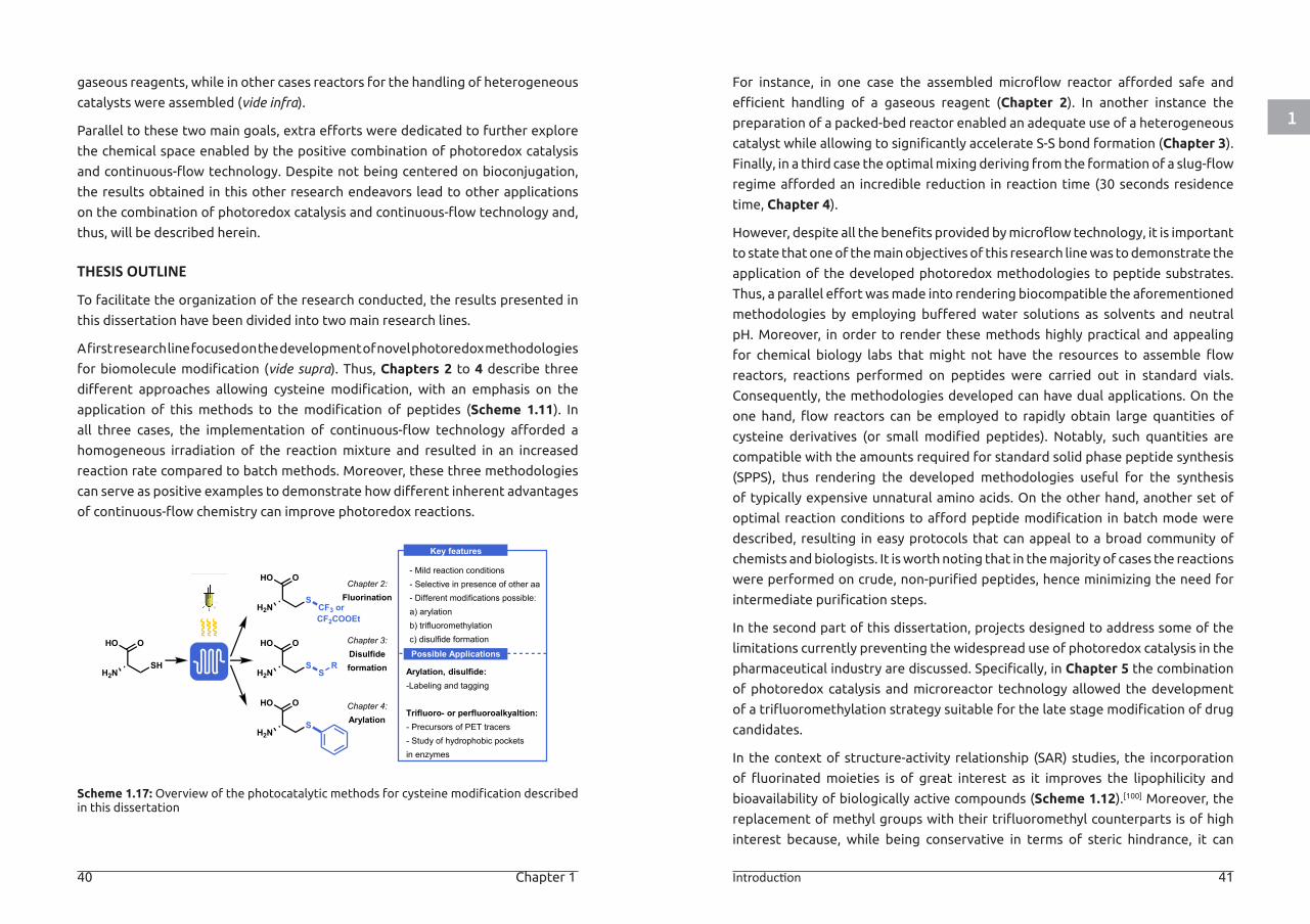
A first research line focused on the development of novel photoredox methodologies
for biomolecule modification (vide supra). Thus, Chapters 2 to 4 describe three
different approaches allowing cysteine modification, with an emphasis on the
application of this methods to the modification of peptides (Scheme 1.11). In
all three cases, the implementation of continuous-flow technology afforded a
homogeneous irradiation of the reaction mixture and resulted in an increased
reaction rate compared to batch methods. Moreover, these three methodologies
can serve as positive examples to demonstrate how different inherent advantages
of continuous-flow chemistry can improve photoredox reactions.
Scheme 1.17: Overview of the photocatalytic methods for cysteine modification described in this dissertation
For instance, in one case the assembled microflow reactor afforded safe and
efficient handling of a gaseous reagent (Chapter 2). In another instance the
preparation of a packed-bed reactor enabled an adequate use of a heterogeneous
catalyst while allowing to significantly accelerate S-S bond formation (Chapter 3).
Finally, in a third case the optimal mixing deriving from the formation of a slug-flow
regime afforded an incredible reduction in reaction time (30 seconds residence
time, Chapter 4).
However, despite all the benefits provided by microflow technology, it is important
to state that one of the main objectives of this research line was to demonstrate the
application of the developed photoredox methodologies to peptide substrates.
Thus, a parallel effort was made into rendering biocompatible the aforementioned
methodologies by employing buffered water solutions as solvents and neutral
pH. Moreover, in order to render these methods highly practical and appealing
for chemical biology labs that might not have the resources to assemble flow
reactors, reactions performed on peptides were carried out in standard vials.
Consequently, the methodologies developed can have dual applications. On the
one hand, flow reactors can be employed to rapidly obtain large quantities of
cysteine derivatives (or small modified peptides). Notably, such quantities are
compatible with the amounts required for standard solid phase peptide synthesis
(SPPS), thus rendering the developed methodologies useful for the synthesis
of typically expensive unnatural amino acids. On the other hand, another set of
optimal reaction conditions to afford peptide modification in batch mode were
described, resulting in easy protocols that can appeal to a broad community of
chemists and biologists. It is worth noting that in the majority of cases the reactions
were performed on crude, non-purified peptides, hence minimizing the need for
intermediate purification steps.
In the second part of this dissertation, projects designed to address some of the
limitations currently preventing the widespread use of photoredox catalysis in the
pharmaceutical industry are discussed. Specifically, in Chapter 5 the combination
of photoredox catalysis and microreactor technology allowed the development
of a trifluoromethylation strategy suitable for the late stage modification of drug
candidates.
In the context of structure-activity relationship (SAR) studies, the incorporation
of fluorinated moieties is of great interest as it improves the lipophilicity and
bioavailability of biologically active compounds (Scheme 1.12).[100] Moreover, the
replacement of methyl groups with their trifluoromethyl counterparts is of high
interest because, while being conservative in terms of steric hindrance, it can
H2N
OHO
SH
H2N
OHO
S
H2N
OHO
S
H2N
OHO
S
CF3 or
SR
Chapter 4:Arylation
Chapter 2:Fluorination
Chapter 3:Disulfideformation
Key features
- Mild reaction conditions- Selective in presence of other aa- Different modifications possible:a) arylationb) trifluoromethylationc) disulfide formation
Arylation, disulfide:-Labeling and tagging
Trifluoro- or perfluoroalkyaltion:- Precursors of PET tracers- Study of hydrophobic pocketsin enzymes
Possible Applications
CF2COOEt
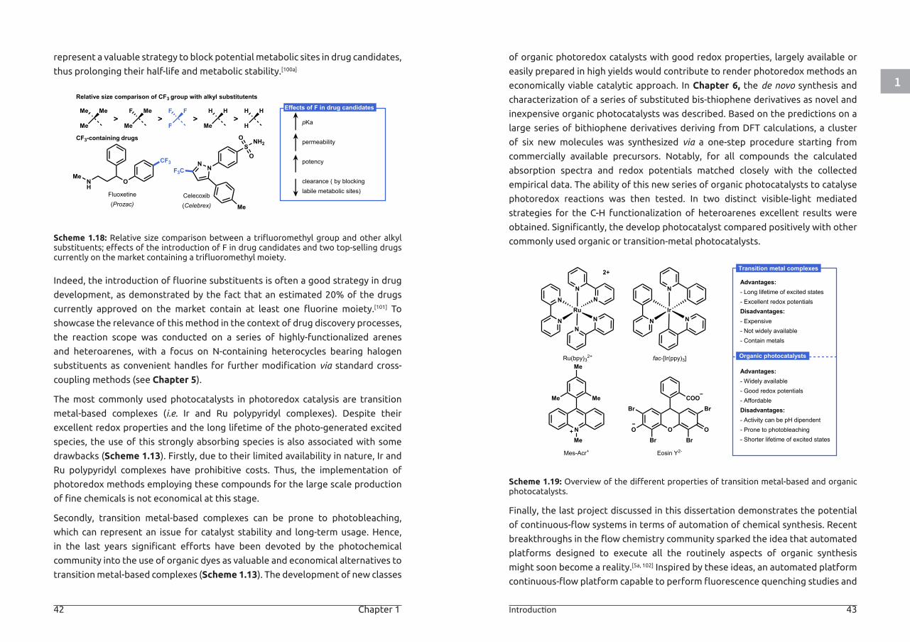
1
42 Chapter 1 Introduction 43
represent a valuable strategy to block potential metabolic sites in drug candidates,
thus prolonging their half-life and metabolic stability.[100a]
Scheme 1.18: Relative size comparison between a trifluoromethyl group and other alkyl substituents; effects of the introduction of F in drug candidates and two top-selling drugs currently on the market containing a trifluoromethyl moiety.
Indeed, the introduction of fluorine substituents is often a good strategy in drug
development, as demonstrated by the fact that an estimated 20% of the drugs
currently approved on the market contain at least one fluorine moiety.[101] To
showcase the relevance of this method in the context of drug discovery processes,
the reaction scope was conducted on a series of highly-functionalized arenes
and heteroarenes, with a focus on N-containing heterocycles bearing halogen
substituents as convenient handles for further modification via standard cross-
coupling methods (see Chapter 5).
The most commonly used photocatalysts in photoredox catalysis are transition
metal-based complexes (i.e. Ir and Ru polypyridyl complexes). Despite their
excellent redox properties and the long lifetime of the photo-generated excited
species, the use of this strongly absorbing species is also associated with some
drawbacks (Scheme 1.13). Firstly, due to their limited availability in nature, Ir and
Ru polypyridyl complexes have prohibitive costs. Thus, the implementation of
photoredox methods employing these compounds for the large scale production
of fine chemicals is not economical at this stage.
Secondly, transition metal-based complexes can be prone to photobleaching,
which can represent an issue for catalyst stability and long-term usage. Hence,
in the last years significant efforts have been devoted by the photochemical
community into the use of organic dyes as valuable and economical alternatives to
transition metal-based complexes (Scheme 1.13). The development of new classes
of organic photoredox catalysts with good redox properties, largely available or
easily prepared in high yields would contribute to render photoredox methods an
economically viable catalytic approach. In Chapter 6, the de novo synthesis and
characterization of a series of substituted bis-thiophene derivatives as novel and
inexpensive organic photocatalysts was described. Based on the predictions on a
large series of bithiophene derivatives deriving from DFT calculations, a cluster
of six new molecules was synthesized via a one-step procedure starting from
commercially available precursors. Notably, for all compounds the calculated
absorption spectra and redox potentials matched closely with the collected
empirical data. The ability of this new series of organic photocatalysts to catalyse
photoredox reactions was then tested. In two distinct visible-light mediated
strategies for the C-H functionalization of heteroarenes excellent results were
obtained. Significantly, the develop photocatalyst compared positively with other
commonly used organic or transition-metal photocatalysts.
Scheme 1.19: Overview of the different properties of transition metal-based and organic photocatalysts.
Finally, the last project discussed in this dissertation demonstrates the potential
of continuous-flow systems in terms of automation of chemical synthesis. Recent
breakthroughs in the flow chemistry community sparked the idea that automated
platforms designed to execute all the routinely aspects of organic synthesis
might soon become a reality.[5a, 102] Inspired by these ideas, an automated platform
continuous-flow platform capable to perform fluorescence quenching studies and
Effects of F in drug candidates
pKa
permeability
potency
clearance ( by blockinglabile metabolic sites)
MeMe
Me
Relative size comparison of CF3 group with alkyl substitutents
>MeF
Me>
FF
F>
HH
Me>
HH
H
CF3
ONH
Me
CF3-containing drugs
Fluoxetine(Prozac)
OS
NN
Me
NH2O
F3C
Celecoxib(Celebrex)
Transition metal complexes
Advantages:- Long lifetime of excited states- Excellent redox potentialsDisadvantages:- Expensive- Not widely available- Contain metals
Organic photocatalystsRu(bpy)32+ fac-[Ir(ppy)3]
Mes-Acr+
N
N
RuN
N
N
N
N
IrN
N
2+
NMe
Me
MeMe
Advantages:- Widely available- Good redox potentials- AffordableDisadvantages:- Activity can be pH dipendent- Prone to photobleaching- Shorter lifetime of excited states
Eosin Y2-
O
COO
Br
Br
OBr
O
Br
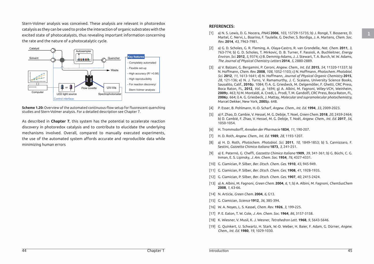
1
44 Chapter 1 Introduction 45
Stern-Volmer analysis was conceived. These analysis are relevant in photoredox
catalysis as they can be used to probe the interaction of organic substrates with the
excited state of photocatalysts, thus revealing important information concerning
the rate and the nature of a photocatalytic cycle.
Scheme 1.20: Overview of the automated continuous-flow setup for fluorescent quenching studies and Stern-Volmer analysis. For a detailed description see Chapter 7.
As described in Chapter 7, this system has the potential to accelerate reaction
discovery in photoredox catalysis and to contribute to elucidate the underlying
mechanisms involved. Overall, compared to manually executed experiments,
the use of the automated system affords accurate and reproducible data while
minimizing human errors
LED light source
Autosampler
or Flow cuvette
SpectrophotometerComputer
Waste
Catalyst
Solvent Quencher
UV-Vis
Control interface
- Completely automated
- Flexible set-up
- High accuracy (R2 >0.98)
- High reproducibility
- For reaction discovery/
Stern-Volmer analysis
Key features
REFERENCES:[1] a) N. S. Lewis, D. G. Nocera, PNAS 2006, 103, 15729-15735; b) J. Rongé, T. Bosserez, D.
Martel, C. Nervi, L. Boarino, F. Taulelle, G. Decher, S. Bordiga, J. A. Martens, Chem. Soc. Rev. 2014, 43, 7963-7981.
[2] a) G. D. Scholes, G. R. Fleming, A. Olaya-Castro, R. van Grondelle, Nat. Chem. 2011, 3, 763-774; b) G. D. Scholes, T. Mirkovic, D. B. Turner, F. Fassioli, A. Buchleitner, Energy Environ. Sci. 2012, 5, 9374; c) B. Demmig-Adams, J. J. Stewart, T. A. Burch, W. W. Adams, The Journal of Physical Chemistry Letters 2014, 5, 2880-2889.
[3] a) V. Balzani, G. Bergamini, P. Ceroni, Angew. Chem., Int. Ed. 2015, 54, 11320-11337; b) N. Hoffmann, Chem. Rev. 2008, 108, 1052-1103; c) N. Hoffmann, Photochem. Photobiol. Sci. 2012, 11, 1613-1641; d) N. Hoffmann, Journal of Physical Organic Chemistry 2015, 28, 121-136; e) N. J. Turro, V. Ramamurthy, J. C. Scaiano, University Science Books, Sausalito, Calif., 2010p. 1084; f) A. G. Griesbeck, M. Oelgemöller, F. Ghetti, CRC Press, Boca Raton, FL, 2012, Vol. ,p. 1694; g) A. Albini, M. Fagnoni, Wiley-VCH, Weinheim, 2009p. 463; h) M. Montaldi, A. Credi, L. Prodi, T. M. Gandolfi, CRC Press, Boca Raton, FL, 2006p. 664; i) A. G. Griesbeck, J. Mattay, Molecular and supramolecular photochemistry, Marcel Dekker, New York, 2005p. 648.
[4] P. Esser, B. Pohlmann, H.-D. Scharf, Angew. Chem., Int. Ed. 1994, 33, 2009-2023.
[5] a) F. Zhao, D. Cambie, V. Hessel, M. G. Debije, T. Noel, Green Chem. 2018, 20, 2459-2464; b) D. Cambié, F. Zhao, V. Hessel, M. G. Debije, T. Noël, Angew. Chem., Int. Ed. 2017, 56, 1050-1054.
[6] H. Trommsdorff, Annalen der Pharmacie 1834, 11, 190-207.
[7] H. D. Roth, Angew. Chem., Int. Ed. 1989, 28, 1193-1207.
[8] a) H. D. Roth, Photochem. Photobiol. Sci. 2011, 10, 1849-1853; b) S. Cannizzaro, F. Sestini, Gazzetta Chimica Italiana 1873, 3, 241-251.
[9] a) E. Paternó, G. Cheffi, Gazzetta Chimica Italiana 1909, 39, 341-361; b) G. Büchi, C. G. Inman, E. S. Lipinsky, J. Am. Chem. Soc. 1954, 76, 4327-4331.
[10] G. Ciamician, P. Silber, Ber. Dtsch. Chem. Ges. 1910, 43, 945-949.
[11] G. Ciamician, P. Silber, Ber. Dtsch. Chem. Ges. 1908, 41, 1928-1935.
[12] G. Ciamician, P. Silber, Ber. Dtsch. Chem. Ges. 1907, 40, 2415-2424.
[13] a) A. Albini, M. Fagnoni, Green Chem. 2004, 6, 1; b) A. Albini, M. Fagnoni, ChemSusChem 2008, 1, 63-66.
[14] N. Article, Green Chem. 2004, 6, G13.
[15] G. Ciamician, Science 1912, 36, 385-394.
[16] W. A. Noyes, L. S. Kassel, Chem. Rev. 1926, 3, 199-225.
[17] P. E. Eaton, T. W. Cole, J. Am. Chem. Soc. 1964, 86, 3157-3158.
[18] K. Wiesner, V. Musil, K. J. Wesner, Tetrahedron Lett. 1968, 9, 5643-5646.
[19] G. Quinkert, U. Schwartz, H. Stark, W.-D. Weber, H. Baier, F. Adam, G. Dürner, Angew. Chem., Int. Ed. 1980, 19, 1029-1030.
1
46 Chapter 1 Introduction 47
[20] M. T. Crimmins, J. M. Pace, P. G. Nantermet, A. S. Kim-Meade, J. B. Thomas, S. H. Watterson, A. S. Wagman, J. Am. Chem. Soc. 2000, 122, 8453-8463.
[21] K.-H. Pfoertner, T. Oppenländer, 2000, DOI: 10.1002/14356007.a19_573.pub2.
[22] S. Poplata, A. Tröster, Y.-Q. Zou, T. Bach, Chem. Rev. 2016, 116, 9748-9815.
[23] a) M. T. Crimmins, Chem. Rev. 1988, 88, 1453-1473; b) D. De Keukeleire, S. L. He, Chem. Rev. 1993, 93, 359-380; c) T. Bach, Synthesis 1998, 1998, 683-703; d) E. Lee-Ruff, G. Mladenova, Chem. Rev. 2003, 103, 1449-1484; e) B. Alcaide, P. Almendros, C. Aragoncillo, Chem. Soc. Rev. 2010, 39, 783-816.
[24] a) M. Quick, A. L. Dobryakov, M. Gerecke, C. Richter, F. Berndt, I. N. Ioffe, A. A. Granovsky, R. Mahrwald, N. P. Ernsting, S. A. Kovalenko, J. Phys. Chem. B 2014, 118, 8756-8771; b) D. H. Waldeck, Chem. Rev. 1991, 91, 415-436.
[25] a) T. Fehrentz, M. Schönberger, D. Trauner, Angew. Chem., Int. Ed. 2011, 50, 12156-12182; b) W. Szymański, J. M. Beierle, H. A. V. Kistemaker, W. A. Velema, B. L. Feringa, Chem. Rev. 2013, 113, 6114-6178; c) S. Erbas-Cakmak, D. A. Leigh, C. T. McTernan, A. L. Nussbaumer, Chem. Rev. 2015, 115, 10081-10206; d) J. Broichhagen, J. A. Frank, D. Trauner, Acc. Chem. Res. 2015, 48, 1947-1960.
[26] D. Budac, P. Wan, Journal of Photochemistry and Photobiology A: Chemistry 1992, 67, 135-166.
[27] a) S. P. Pitre, C. D. McTiernan, J. C. Scaiano, Acc. Chem. Res. 2016, 49, 1320-1330; b) D. M. Arias-Rotondo, J. K. McCusker, Chem. Soc. Rev. 2016, 45, 5803-5820.
[28] D. M. Hedstrand, W. H. Kruizinga, R. M. Kellogg, Tetrahedron Lett. 1978, 19, 1255-1258.
[29] a) K. Hironaka, S. Fukuzumi, T. Tanaka, Journal of the Chemical Society, Perkin Transactions 2 1984, DOI: 10.1039/P29840001705, 1705-1709; b) C. Pac, M. Ihama, M. Yasuda, Y. Miyauchi, H. Sakurai, J. Am. Chem. Soc. 1981, 103, 6495-6497.
[30] K. Okada, K. Okamoto, N. Morita, K. Okubo, M. Oda, J. Am. Chem. Soc. 1991, 113, 9401-9402.
[31] a) D. A. Nagib, D. W. C. MacMillan, Nature 2011, 480, 224-228; b) S. Lin, M. A. Ischay, C. G. Fry, T. P. Yoon, J. Am. Chem. Soc. 2011, 133, 19350-19353; c) M. A. Ischay, M. E. Anzovino, J. Du, T. P. Yoon, J. Am. Chem. Soc. 2008, 130, 12886-12887; d) J. Du, T. P. Yoon, J. Am. Chem. Soc. 2009, 131, 14604-14605; e) D. A. Nicewicz, D. W. C. MacMillan, Science 2008, 322, 77-80; f) C. J. Wallentin, J. D. Nguyen, P. Finkbeiner, C. R. J. Stephenson, J. Am. Chem. Soc. 2012, 134, 8875-8884; g) J. W. Beatty, C. R. J. Stephenson, J. Am. Chem. Soc. 2014, 136, 10270-10273; h) J. W. Beatty, J. J. Douglas, K. P. Cole, C. R. J. Stephenson, Nat Commun 2015, 6, 7919.
[32] C. K. Prier, D. A. Rankic, D. W. C. MacMillan, Chem. Rev. 2013, 113, 5322-5363.
[33] a) N. A. Romero, D. A. Nicewicz, Chem. Rev. 2016, 116, 10075-10166; b) D. M. Schultz, T. P. Yoon, Science 2014, 343, 1239176-1239176; c) J. Xuan, W.-J. Xiao, Angew. Chem., Int. Ed. 2012, 51, 6828-6838; d) T. P. Yoon, M. A. Ischay, J. Du, Nat. Chem. 2010, 2, 527-532; e) J. J. Douglas, J. D. Nguyen, K. P. Cole, C. R. J. Stephenson, Aldrichim Acta 2014, 47, 15-25; f) R. A. Angnes, Z. Li, C. R. D. Correia, G. B. Hammond, Org. Biomol. Chem. 2015, 13, 9152-9167; g) K. Zeitler, Angew. Chem., Int. Ed. 2009, 48, 9785-9789.
[34] K. Kalyanasundaram, Coord. Chem. Rev. 1982, 46, 159-244.
[35] a) V. Balzani, S. Campagna, 2007, 281; b) J. K. McCusker, Acc. Chem. Res. 2003, 36, 876-887.
[36] D. Ziegenbalg, B. Wriedt, G. Kreisel, D. Kralisch, Chem. Eng. Technol. 2016, 39, 123-134.
[37] A. Studer, D. P. Curran, Angew. Chem. Int. Ed. 2016, 55, 58-102.
[38] a) M. A. Cismesia, T. P. Yoon, Chem. Sci. 2015, 6, 5426-5434; b) M. Majek, F. Filace, A. J. v. Wangelin, Beilstein J. Org. Chem. 2014, 10, 981-989; c) M. D. Karkas, B. S. Matsuura, C. R. J. Stephenson, Science 2015, 349, 1285-1286.
[39] D. Cambié, C. Bottecchia, N. J. W. Straathof, V. Hessel, T. Noël, Chem. Rev. 2016, 116, 10276-10341.
[40] a) O. Koniev, A. Wagner, Chem. Soc. Rev. 2015, 44, 5495-5551; b) O. Boutureira, G. J. L. Bernardes, Chem. Rev. 2015, 115, 2174-2195; c) Q.-Y. Hu, F. Berti, R. Adamo, Chem. Soc. Rev. 2016, 45, 1691-1719.
[41] a) J. N. deGruyter, L. R. Malins, P. S. Baran, Biochemistry 2017, 56, 3863-3873; b) N. Krall, F. P. da Cruz, O. Boutureira, G. J. L. Bernardes, Nat Chem 2016, 8, 103-113; c) C. D. Spicer, B. G. Davis, Nat. Commun. 2014, 5, 4740.
[42] a) E. M. Sletten, C. R. Bertozzi, Angew. Chem., Int. Ed. 2009, 48, 6974-6998; b) D. M. Patterson, J. A. Prescher, Curr. Opin. Chem. Biol. 2015, 28, 141-149; c) E. M. Milczek, Chem. Rev. 2017, 118, 119-141; d) H.-W. Shih, D. N. Kamber, J. A. Prescher, Curr. Opin. Chem. Biol. 2014, 21, 103-111.
[43] a) J. M. Chalker, G. J. L. Bernardes, B. G. Davis, Acc. Chem. Res. 2011, 44, 730-741; b) J. M. Chalker, S. B. Gunnoo, O. Boutureira, S. C. Gerstberger, M. Fernández-González, G. J. L. Bernardes, L. Griffin, H. Hailu, C. J. Schofield, B. G. Davis, Chem. Sci. 2011, 2, 1666-1676; c) E. V. Vinogradova, C. Zhang, A. M. Spokoyny, B. L. Pentelute, S. L. Buchwald, Nature 2015, 526, 687-691; d) A. J. Rojas, C. Zhang, E. V. Vinogradova, N. H. Buchwald, J. Reilly, B. L. Pentelute, S. L. Buchwald, Chem. Sci. 2017, 8, 4257-4263; e) C. Zhang, M. Welborn, T. Zhu, N. J. Yang, M. S. Santos, T. Van Voorhis, B. L. Pentelute, Nat. Chem. 2015, 8, 120-128; f) A. M. Spokoyny, Y. Zou, J. J. Ling, H. Yu, Y.-S. Lin, B. L. Pentelute, J. Am. Chem. Soc. 2013, 135, 5946-5949.
[44] D. I. Pattison, A. S. Rahmanto, M. J. Davies, Photochem. Photobiol. Sci. 2012, 11, 38-53.
[45] Y. Su, K. P. L. Kuijpers, N. König, M. Shang, V. Hessel, T. Noël, Chem. - Eur. J. 2016, 22, 12295-12300.
[46] S. B. Gunnoo, A. Madder, ChemBioChem 2016, 17, 529-553.
[47] a) C. E. Hoyle, C. N. Bowman, Angew. Chem., Int. Ed. 2010, 49, 1540-1573; b) A. Dondoni, Angew. Chem., Int. Ed. 2008, 47, 8995-8997.
[48] M. H. Keylor, J. E. Park, C.-J. Wallentin, C. R. J. Stephenson, Tetrahedron 2014, 70, 4264-4269.
[49] E. L. Tyson, M. S. Ament, T. P. Yoon, J. Org. Chem. 2013, 78, 2046-2050.
[50] G. Zhao, S. Kaur, T. Wang, Org. Lett. 2017, 19, 3291-3294.
[51] E. L. Tyson, Z. L. Niemeyer, T. P. Yoon, J. Org. Chem. 2014, 79, 1427-1436.
[52] a) X.-F. Gao, J.-J. Du, Z. Liu, J. Guo, Org. Lett. 2016, 18, 1166-1169; b) M. Lee, S. Neukirchen, C. Cabrele, O. Reiser, J. Pept. Sci. 2017, 23, 556-562.
[53] B. A. Vara, X. Li, S. Berritt, C. R. Walters, E. J. Petersson, G. A. Molander, Chem. Sci. 2018, 9, 336-344.
1
48 Chapter 1 Introduction 49
[54] N. Ichiishi, J. P. Caldwell, M. Lin, W. Zhong, X. Zhu, E. Streckfuss, H.-Y. Kim, C. A. Parish, S. W. Krska, Chem. Sci. 2018, 9, 4168-4175.
[55] S. Sato, H. Nakamura, Angew. Chem., Int. Ed. 2013, 52, 8681-8684.
[56] S. Sato, S. Ishii, H. Nakamura, Eur. J. Inorg. Chem. 2017, 2017, 4406-4410.
[57] a) S. Lin, X. Yang, S. Jia, A. M. Weeks, M. Hornsby, P. S. Lee, R. V. Nichiporuk, A. T. Iavarone, J. A. Wells, F. D. Toste, C. J. Chang, Science 2017, 355, 597-602; b) Y. Shechter, Y. Burstein, A. Patchornik, Biochemistry 1975, 14, 4497-4503; c) J. R. Kramer, T. J. Deming, Chem. Commun. 2013, 49, 5144-5146; d) T. J. Deming, Bioconjugate Chem. 2017, 28, 691-700.
[58] K. Lindorff-Larsen, J. R. Winther, Anal. Biochem. 2000, 286, 308-310.
[59] N. Brot, H. Weissbach, Trends Biochem. Sci. 1982, 7, 137-139.
[60] a) R. Levine, J. Moskovitz, E. Stadtman, IUBMB Life 2001, 50, 301-307; b) R. L. Levine, L. Mosoni, B. S. Berlett, E. R. Stadtman, PNAS 1996, 93, 15036-15040.
[61] N. Emmanuel, C. Mendoza, M. Winter, C. R. Horn, A. Vizza, L. Dreesen, B. Heinrichs, J.-C. M. Monbaliu, Org. Process Res. Dev. 2017, 21, 1435-1438.
[62] D. Gilis, S. Massar, N. J. Cerf, M. Rooman, Genome Biol. 2001, 2, research0049.0041.
[63] M. H. Smith, J. Theor. Biol. 1966, 13, 261-282.
[64] a) Y. Seki, T. Ishiyama, D. Sasaki, J. Abe, Y. Sohma, K. Oisaki, M. Kanai, J. Am. Chem. Soc. 2016, 138, 10798-10801; b) M. B. Hansen, F. Hubálek, T. Skrydstrup, T. Hoeg-Jensen, Chem. - Eur. J. 2016, 22, 1572-1576; c) A. Schischko, H. Ren, N. Kaplaneris, L. Ackermann, Angew. Chem., Int. Ed. 2017, 56, 1576-1580; d) J. Ruiz-Rodríguez, F. Albericio, R. Lavilla, Chem. - Eur. J. 2010, 16, 1124-1127; e) A. J. Reay, T. J. Williams, I. J. S. Fairlamb, Org. Biomol. Chem. 2015, 13, 8298-8309; f) W. Siti, A. K. Khan, H.-P. M. de Hoog, B. Liedberg, M. Nallani, Org. Biomol. Chem. 2015, 13, 3202-3206.
[65] a) Z. Ruan, N. Sauermann, E. Manoni, L. Ackermann, Angew. Chem., Int. Ed. 2017, 56, 3172-3176; b) J. M. Antos, J. M. McFarland, A. T. Iavarone, M. B. Francis, J. Am. Chem. Soc. 2009, 131, 6301-6308; c) J. M. Antos, M. B. Francis, J. Am. Chem. Soc. 2004, 126, 10256-10257.
[66] Y. Yu, L.-K. Zhang, A. V. Buevich, G. Li, H. Tang, P. Vachal, S. L. Colletti, Z.-C. Shi, J. Am. Chem. Soc. 2018, DOI: 10.1021/jacs.8b03973.
[67] S. Bloom, C. Liu, D. K. Kölmel, J. X. Qiao, Y. Zhang, M. A. Poss, W. R. Ewing, D. W. C. MacMillan, Nat. Chem. 2017, 10, 205-211.
[68] M. A. T. Blaskovich, J. Med. Chem. 2016, 59, 10807-10836.
[69] a) J. Günther, Angew. Chem., Int. Ed. 1991, 30, 1051-1068; b) J. M. Gavaret, J. Nunez, H. J. Cahnmann, J. Biol. Chem. 1980, 255, 5281-5285.
[70] L. M. Repka, J. R. Chekan, S. K. Nair, W. A. van der Donk, Chem. Rev. 2017, 117, 5457-5520.
[71] N. M. Okeley, Y. Zhu, W. A. van der Donk, Org. Lett. 2000, 2, 3603-3606.
[72] a) G. J. L. Bernardes, J. M. Chalker, J. C. Errey, B. G. Davis, J. Am. Chem. Soc. 2008, 130, 5052-5053; b) C. J. Chapman, K. J. Wadsworth, C. G. Frost, J. Organomet. Chem. 2003, 680, 206-211; c) C. J. Chapman, A. Matsuno, C. G. Frost, M. C. Willis, Chem. Commun.
2007, 38, 3903-3905; d) H. M. Key, S. J. Miller, J. Am. Chem. Soc. 2017, 139, 15460-15466.
[73] R. A. Aycock, D. B. Vogt, N. T. Jui, Chem. Sci. 2017, 8, 7998-8003.
[74] A. L. J. Beckwith, C. L. L. Chai, J. Chem. Soc., Chem. Commun. 1990, 16, 1087-1088.
[75] A. D. de Bruijn, G. Roelfes, Chem. - Eur. J. 2018, DOI: 10.1002/chem.201803144.
[76] S. K. Teoh, C. Rathi, P. Sharratt, Org. Process Res. Dev. 2016, 20, 414-431.
[77] S. G. Newman, K. F. Jensen, Green Chem. 2013, 15, 1456-1472.
[78] M. B. Plutschack, B. Pieber, K. Gilmore, P. H. Seeberger, Chem. Rev. 2017, 117, 11796-11893.
[79] R. Porta, M. Benaglia, A. Puglisi, Org. Process Res. Dev. 2015, DOI: 10.1021/acs.oprd.5b00325.
[80] a) H. P. L. Gemoets, Y. Su, M. Shang, V. Hessel, R. Luque, T. Noël, Chem. Soc. Rev. 2015, 45, 83-117; b) B. Gutmann, D. Cantillo, C. O. Kappe, Angew. Chem., Int. Ed. 2015, 54, 6688-6728; c) M. Movsisyan, E. I. P. Delbeke, J. K. E. T. Berton, C. Battilocchio, S. V. Ley, C. V. Stevens, Chem. Soc. Rev. 2016, 45, 4892-4928.
[81] a) S. V. Ley, D. E. Fitzpatrick, R. J. Ingham, R. M. Myers, Angew. Chem., Int. Ed. 2015, 54, 3449-3464; b) D. C. Fabry, E. Sugiono, M. Rueping, Israel Journal of Chemistry 2014, 54, 341-350; c) D. C. Fabry, E. Sugiono, M. Rueping, React. Chem. Eng. 2016, DOI: 10.1039/c5re00038f.
[82] Y. Su, N. J. W. Straathof, V. Hessel, T. Noël, Chem. - Eur. J. 2014, 20, 10562-10589.
[83] a) R. L. Hartman, J. P. McMullen, K. F. Jensen, Angew. Chem. Int. Ed. 2011, 50, 7502-7519; b) I. Vural Gürsel, T. Noël, Q. Wang, V. Hessel, Green Chem. 2015, 17, 2012-2026.
[84] a) L. Capretto, W. Cheng, M. Hill, X. Zhang, 2011, 304, 27-68; b) V. Hessel, H. Löwe, F. Schönfeld, Chemical Engineering Science 2005, 60, 2479-2501; c) L. Falk, J. M. Commenge, Chemical Engineering Science 2010, 65, 405-411.
[85] J. Yoshida, A. Nagaki, T. Iwasaki, S. Suga, Chem. Eng. Technol. 2005, 28, 259-266.
[86] a) T. Noël, V. Hessel, ChemSusChem 2013, 6, 405-407; b) C. J. Mallia, I. R. Baxendale, Org. Process Res. Dev. 2016, DOI: 10.1021/acs.oprd.5b00222.
[87] M. Brzozowski, M. O’Brien, S. V. Ley, A. Polyzos, Acc. Chem. Res. 2015, 48, 349-362.
[88] a) A. Puglisi, M. Benaglia, R. Porta, F. Coccia, Curr. Organocatal. 2015, 2, 79-101; b) V. Hessel, T. Noel, Chim. Oggi 2015, 33, 44-49.
[89] a) K. Nakata, A. Fujishima, J. Photochem. Photobiol., C 2012, 13, 169-189; b) J. Schneider, M. Matsuoka, M. Takeuchi, J. Zhang, Y. Horiuchi, M. Anpo, D. W. Bahnemann, Chem. Rev. 2014, 114, 9919-9986; c) A. Fujishima, X. Zhang, D. Tryk, Surface Science Reports 2008, 63, 515-582.
[90] a) R. Munirathinam, J. Huskens, W. Verboom, Adv. Synth. Catal. 2015, 357, 1093-1123; b) R. Ricciardi, J. Huskens, W. Verboom, ChemSusChem 2015, 8, 2586-2605.
[91] S.-i. In, M. G. Nielsen, P. C. K. Vesborg, Y. Hou, B. L. Abrams, T. R. Henriksen, O. Hansen, I. Chorkendorff, Chem. Commun. 2011, 47, 2613-2615.
[92] R. Gorges, S. Meyer, G. Kreisel, Journal of Photochemistry and Photobiology A: Chemistry 2004, 167, 95-99.
50 Chapter 1
[93] H. C. Aran, D. Salamon, T. Rijnaarts, G. Mul, M. Wessling, R. G. H. Lammertink, Journal of Photochemistry and Photobiology A: Chemistry 2011, 225, 36-41.
[94] C. Liebner, J. Fischer, S. Heinrich, T. Lange, H. Hieronymus, E. Klemm, Process Safety and Environmental Protection 2012, 90, 77-82.
[95] a) D. Webb, T. F. Jamison, Chem. Sci. 2010, 1, 675-675; b) J. C. Pastre, D. L. Browne, S. V. Ley, Chem. Soc. Rev. 2013, 42, 8849-8869.
[96] a) L. D. Elliott, J. P. Knowles, P. J. Koovits, K. G. Maskill, M. J. Ralph, G. Lejeune, L. J. Edwards, R. I. Robinson, I. R. Clemens, B. Cox, D. D. Pascoe, G. Koch, M. Eberle, M. B. Berry, K. I. Booker-Milburn, Chem. - Eur. J. 2014, 20, 15226-15232; b) E. E. Coyle, M. Oelgemöller, Photochemical & photobiological sciences : Official journal of the European Photochemistry Association and the European Society for Photobiology 2008, 7, 1313-1322; c) M. Oelgemöller, O. Shvydkiv, Molecules 2011, 16, 7522-7550; d) M. Oelgemoeller, Chemical Engineering and Technology 2012, 35, 1144-1152.
[97] A. Yavorskyy, O. Shvydkiv, N. Hoffmann, K. Nolan, M. Oelgemöller, Org. Lett. 2012, 14, 4342-4345.
[98] Y. Su, K. Kuijpers, V. Hessel, T. Noël, React. Chem. Eng. 2016, 1, 73-81.
[99] K. P. L. Kuijpers, M. A. H. van Dijk, Q. G. Rumeur, V. Hessel, Y. Su, T. Noel, React. Chem. Eng. 2017, 2, 109-115.
[100] a) Y. Zhou, J. Wang, Z. Gu, S. Wang, W. Zhu, J. L. Aceña, V. A. Soloshonok, K. Izawa, H. Liu, Chem. Rev. 2016, 116, 422-518; b) S. Purser, P. R. Moore, S. Swallow, V. Gouverneur, Chem. Soc. Rev. 2008, 37, 320-330.
[101] H. Zhang, Journal of Biomolecular Research & Therapeutics 2013, 01.
[102] a) H.-W. Hsieh, C. W. Coley, L. M. Baumgartner, K. F. Jensen, R. I. Robinson, Org. Process Res. Dev. 2018, 22, 542-550; b) C. W. Coley, M. Abolhasani, H. Lin, K. F. Jensen, Angew. Chem., Int. Ed. 2017, 56, 9847-9850; c) S. V. Ley, D. E. Fitzpatrick, R. M. Myers, C. Battilocchio, R. J. Ingham, Angew. Chem., Int. Ed. 2015, 54, 10122-10136; d) J. P. McMullen, M. T. Stone, S. L. Buchwald, K. F. Jensen, Angew. Chem., Int. Ed. 2010, 49, 7076-7080; e) D. E. Fitzpatrick, C. Battilocchio, S. V. Ley, ACS Central Science 2016, 2, 131-138; f) B. J. Reizman, K. F. Jensen, Acc. Chem. Res. 2016, 49, 1786-1796; g) K. S. Elvira, X. C. i Solvas, R. C. R. Wootton, A. J. deMello, Nat. Chem. 2013, 5, 905-915.
CHAPTER 2
Visible light-induced trifluoromethylation and perfluoroalkylation of cysteine in batch and continuous flow
This chapter is based on:
Bottecchia, C.; Wei, X.-J.; Kuijpers, K. P. L.; Hessel, V.; Noël, T., J. Org. Chem., 2016, 81, 7301-7307
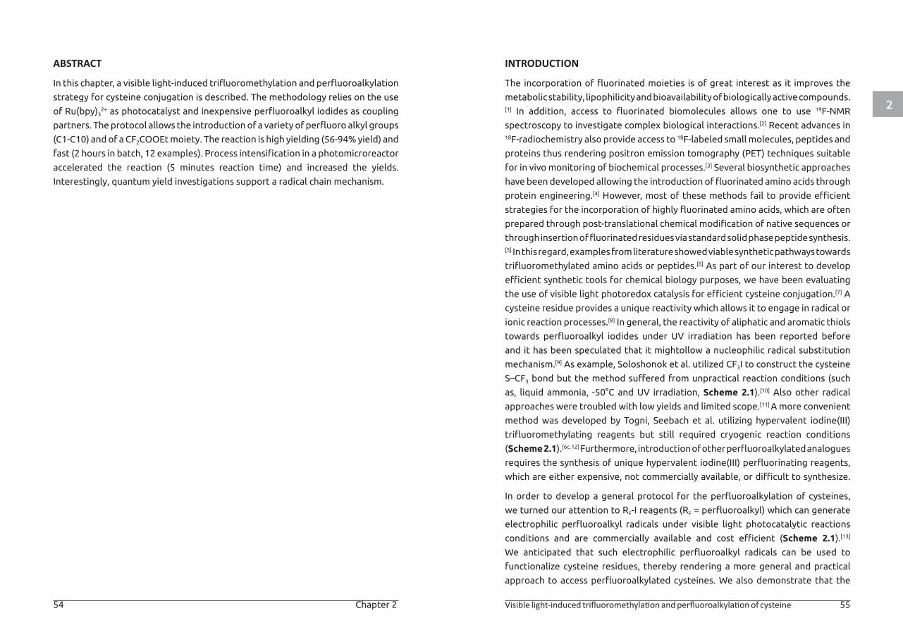
2
54 Chapter 2 Visible light-induced trifluoromethylation and perfluoroalkylation of cysteine 55
ABSTRACT
In this chapter, a visible light-induced trifluoromethylation and perfluoroalkylation
strategy for cysteine conjugation is described. The methodology relies on the use
of Ru(bpy)32+ as photocatalyst and inexpensive perfluoroalkyl iodides as coupling
partners. The protocol allows the introduction of a variety of perfluoro alkyl groups
(C1-C10) and of a CF2COOEt moiety. The reaction is high yielding (56-94% yield) and
fast (2 hours in batch, 12 examples). Process intensification in a photomicroreactor
accelerated the reaction (5 minutes reaction time) and increased the yields.
Interestingly, quantum yield investigations support a radical chain mechanism.
INTRODUCTION
The incorporation of fluorinated moieties is of great interest as it improves the
metabolic stability, lipophilicity and bioavailability of biologically active compounds.[1] In addition, access to fluorinated biomolecules allows one to use 19F-NMR
spectroscopy to investigate complex biological interactions.[2] Recent advances in 18F-radiochemistry also provide access to 18F-labeled small molecules, peptides and
proteins thus rendering positron emission tomography (PET) techniques suitable
for in vivo monitoring of biochemical processes.[3] Several biosynthetic approaches
have been developed allowing the introduction of fluorinated amino acids through
protein engineering.[4] However, most of these methods fail to provide efficient
strategies for the incorporation of highly fluorinated amino acids, which are often
prepared through post-translational chemical modification of native sequences or
through insertion of fluorinated residues via standard solid phase peptide synthesis.[5] In this regard, examples from literature showed viable synthetic pathways towards
trifluoromethylated amino acids or peptides.[6] As part of our interest to develop
efficient synthetic tools for chemical biology purposes, we have been evaluating
the use of visible light photoredox catalysis for efficient cysteine conjugation.[7] A
cysteine residue provides a unique reactivity which allows it to engage in radical or
ionic reaction processes.[8] In general, the reactivity of aliphatic and aromatic thiols
towards perfluoroalkyl iodides under UV irradiation has been reported before
and it has been speculated that it mightollow a nucleophilic radical substitution
mechanism.[9] As example, Soloshonok et al. utilized CF3I to construct the cysteine
S–CF3 bond but the method suffered from unpractical reaction conditions (such
as, liquid ammonia, -50°C and UV irradiation, Scheme 2.1).[10] Also other radical
approaches were troubled with low yields and limited scope.[11] A more convenient
method was developed by Togni, Seebach et al. utilizing hypervalent iodine(III)
trifluoromethylating reagents but still required cryogenic reaction conditions
(Scheme 2.1).[6c, 12] Furthermore, introduction of other perfluoroalkylated analogues
requires the synthesis of unique hypervalent iodine(III) perfluorinating reagents,
which are either expensive, not commercially available, or difficult to synthesize.
In order to develop a general protocol for the perfluoroalkylation of cysteines,
we turned our attention to RF-I reagents (RF = perfluoroalkyl) which can generate
electrophilic perfluoroalkyl radicals under visible light photocatalytic reactions
conditions and are commercially available and cost efficient (Scheme 2.1).[13]
We anticipated that such electrophilic perfluoroalkyl radicals can be used to
functionalize cysteine residues, thereby rendering a more general and practical
approach to access perfluoroalkylated cysteines. We also demonstrate that the
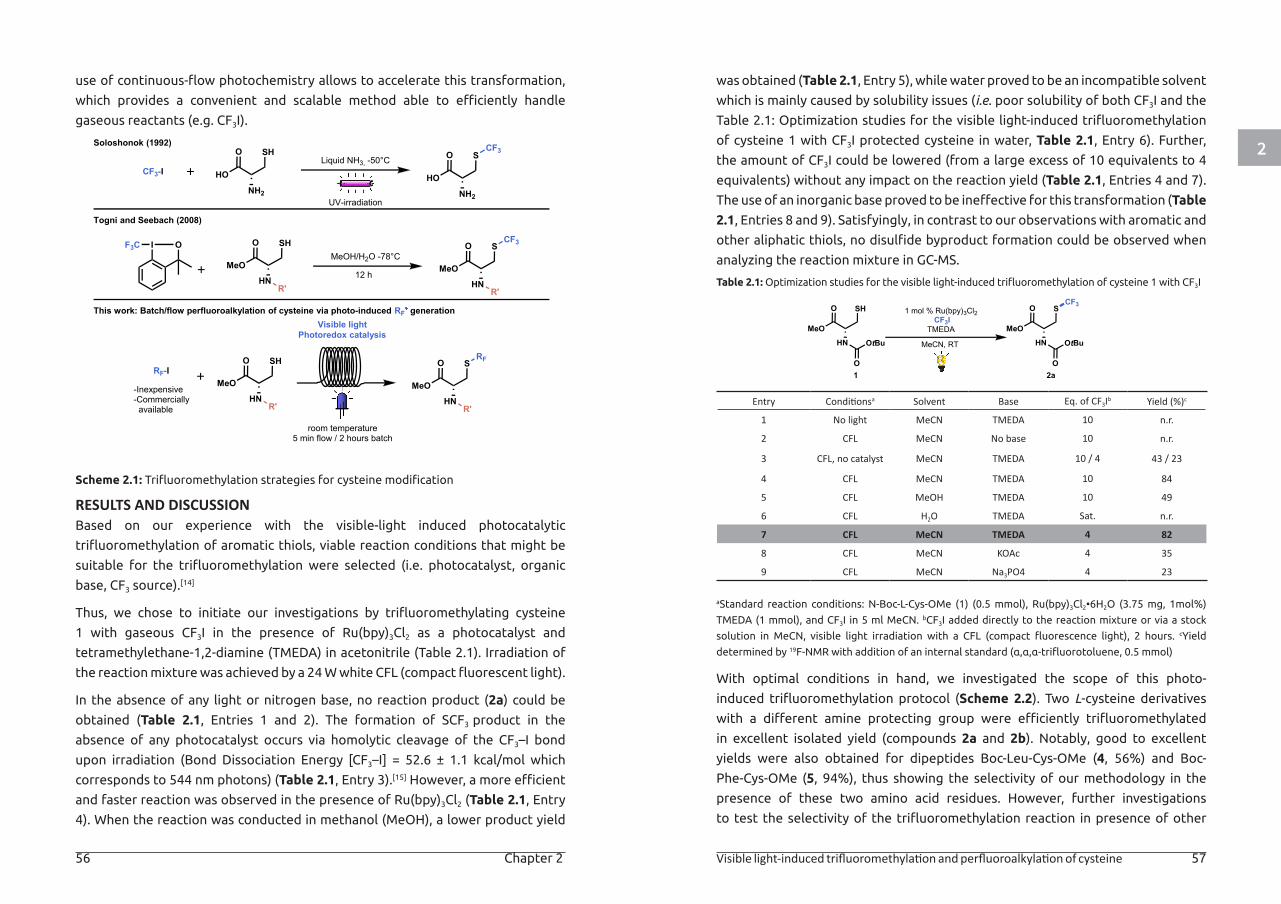
2
56 Chapter 2 Visible light-induced trifluoromethylation and perfluoroalkylation of cysteine 57
use of continuous-flow photochemistry allows to accelerate this transformation,
which provides a convenient and scalable method able to efficiently handle
gaseous reactants (e.g. CF3I).
Scheme 2.1: Trifluoromethylation strategies for cysteine modification
RESULTS AND DISCUSSIONBased on our experience with the visible-light induced photocatalytic
trifluoromethylation of aromatic thiols, viable reaction conditions that might be
suitable for the trifluoromethylation were selected (i.e. photocatalyst, organic
base, CF3 source).[14]
Thus, we chose to initiate our investigations by trifluoromethylating cysteine
1 with gaseous CF3I in the presence of Ru(bpy)3Cl2 as a photocatalyst and
tetramethylethane-1,2-diamine (TMEDA) in acetonitrile (Table 2.1). Irradiation of
the reaction mixture was achieved by a 24 W white CFL (compact fluorescent light).
In the absence of any light or nitrogen base, no reaction product (2a) could be
obtained (Table 2.1, Entries 1 and 2). The formation of SCF3 product in the
absence of any photocatalyst occurs via homolytic cleavage of the CF3–I bond
upon irradiation (Bond Dissociation Energy [CF3–I] = 52.6 ± 1.1 kcal/mol which
corresponds to 544 nm photons) (Table 2.1, Entry 3).[15] However, a more efficient
and faster reaction was observed in the presence of Ru(bpy)3Cl2 (Table 2.1, Entry
4). When the reaction was conducted in methanol (MeOH), a lower product yield
This work: Batch/flow perfluoroalkylation of cysteine via photo-induced RF generation
RF-I
-Inexpensive-Commerciallyavailable
HN
O SH
MeO
R' HN
O
MeO
R'
SRF
Visible lightPhotoredox catalysis
room temperature5 min flow / 2 hours batch
MeOH/H2O -78°C
Togni and Seebach (2008)
I OF3C
HN
O SH
MeO
R' HN
O
MeO
R'
SCF3
12 h
Liquid NH3, -50°C
NH2
O S
HO
CF3
NH2
O SH
HO
Soloshonok (1992)
CF3-I
UV-irradiation
was obtained (Table 2.1, Entry 5), while water proved to be an incompatible solvent
which is mainly caused by solubility issues (i.e. poor solubility of both CF3I and the
Table 2.1: Optimization studies for the visible light-induced trifluoromethylation
of cysteine 1 with CF3I protected cysteine in water, Table 2.1, Entry 6). Further,
the amount of CF3I could be lowered (from a large excess of 10 equivalents to 4
equivalents) without any impact on the reaction yield (Table 2.1, Entries 4 and 7).
The use of an inorganic base proved to be ineffective for this transformation (Table
2.1, Entries 8 and 9). Satisfyingly, in contrast to our observations with aromatic and
other aliphatic thiols, no disulfide byproduct formation could be observed when
analyzing the reaction mixture in GC-MS.
Table 2.1: Optimization studies for the visible light-induced trifluoromethylation of cysteine 1 with CF3I
Entry Conditionsa Solvent Base Eq. of CF3Ib Yield (%)c
1 No light MeCN TMEDA 10 n.r.
2 CFL MeCN No base 10 n.r.
3 CFL, no catalyst MeCN TMEDA 10 / 4 43 / 23
4 CFL MeCN TMEDA 10 84
5 CFL MeOH TMEDA 10 49
6 CFL H2O TMEDA Sat. n.r.
7 CFL MeCN TMEDA 4 82
8 CFL MeCN KOAc 4 35
9 CFL MeCN Na3PO4 4 23
aStandard reaction conditions: N-Boc-L-Cys-OMe (1) (0.5 mmol), Ru(bpy)3Cl2•6H2O (3.75 mg, 1mol%)
TMEDA (1 mmol), and CF3I in 5 ml MeCN. bCF3I added directly to the reaction mixture or via a stock
solution in MeCN, visible light irradiation with a CFL (compact fluorescence light), 2 hours. cYield
determined by 19F-NMR with addition of an internal standard (α,α,α-trifluorotoluene, 0.5 mmol)
With optimal conditions in hand, we investigated the scope of this photo-
induced trifluoromethylation protocol (Scheme 2.2). Two L-cysteine derivatives
with a different amine protecting group were efficiently trifluoromethylated
in excellent isolated yield (compounds 2a and 2b). Notably, good to excellent
yields were also obtained for dipeptides Boc-Leu-Cys-OMe (4, 56%) and Boc-
Phe-Cys-OMe (5, 94%), thus showing the selectivity of our methodology in the
presence of these two amino acid residues. However, further investigations
to test the selectivity of the trifluoromethylation reaction in presence of other
MeCN, RT
1 mol % Ru(bpy)3Cl2CF3I
TMEDA
1 2a
HN
O S
MeO
OtBu
O
CF3
HN
O SH
MeO
OtBu
O
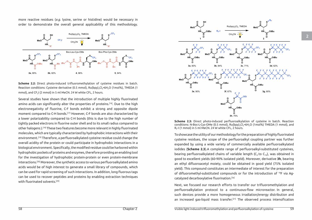
2
58 Chapter 2 Visible light-induced trifluoromethylation and perfluoroalkylation of cysteine 59
more reactive residues (e.g. lysine, serine or histidine) would be necessary in
order to demonstrate the overall general applicability of this methodology.
Scheme 2.2: Direct photo-induced trifluoromethylation of cysteine residues in batch.
Reaction conditions: Cysteine derivative (0.5 mmol), Ru(bpy)3Cl2•6H2O (1mol%), TMEDA (1
mmol), and CF3I (2 mmol) in 5 ml MeCN. 24 W white CFL, 2 hours.
Several studies have shown that the introduction of multiple highly fluorinated
amino acids can significantly alter the properties of proteins.[16]. Due to the high
electronegativity of fluorine, C-F bonds exhibit a strong and opposite dipole
moment compared to C-H bonds.[17] However, C-F bonds are also characterized by
a lower polarizability compared to C-H bonds (this is due to the high number of
tightly packed electrons in fluorine outer shell and to its small radius compared to
other halogens ).[18] These two features become more relevant in highly fluorinated
molecules, which are typically characterized by hydrophobic interactions with their
environment.[19] Therefore, a perfluoroalkylated cysteine residue could change the
overall acidity of the protein or could participate in hydrophobic interactions in a
biological environment. Specifically, the modified residue could be harbored within
hydrophobic pockets of proteins and enzymes, therefore providing an enabling tool
for the investigation of hydrophobic protein-protein or even protein-membrane
interactions.[5b] Moreover, the synthetic access to various perfluoroalkylated amino
acids would be of high interest to generate a small library of compounds, which
can be used for rapid screening of such interactions. In addition, long fluorous tags
can be used to recover peptides and proteins by enabling extraction techniques
with fluorinated solvents.[20]
2a, 90%
Ru(bpy)3Cl2, TMEDA
CH3CNCF3I
2b, 82% 4, 96% 5, 94%
HN
O S
MeOOtBu
O
CF3
HN
O S
MeOMe
O
CF3O
HN
iPrO
O
ONH
S
OMeCF3
tBu
Boc-Leu-Cys-OMe
OHN
BnO
O
ONH
S
OMeCF3
tBu
Boc-Phe-Cys-OMe
HN
O SH
MeO
R'HN
O
MeO
R'
SCF3
Scheme 2.3: Direct photo-induced perfluoroalkylation of cysteine in batch. Reaction conditions: N-Boc-L-Cys-OMe (0.5 mmol), Ru(bpy)3Cl2•6H2O (1mol%) TMEDA (1 mmol), and RF-I (1 mmol) in 5 ml MeCN. 24 W white CFL, 2 hours.
To showcase the utility of our methodology for the preparation of highly fluorinated
cysteine residues, the scope of the perfluoroalkyl coupling partner was further
expanded by using a wide variety of commercially available perfluoroalkylated
iodides (Scheme 2.3).A complete range of perfluoroalkyl-substituted cysteines,
bearing perfluoroalkylated chains of variable length (C3 to C10), was obtained in
good to excellent yields (60-90% isolated yield). Moreover, derivative 3h, bearing
an ethyl difluoroacetyl moiety, could be obtained in good yield (75% isolated
yield). This compound constitutes an intermediate of interest for the preparation
of difluoromethyl-substituted compounds or for the introduction of 18F via Ag-
catalyzed decarboxylative fluorination.[3a]
Next, we focused our research efforts to transfer our trifluoromethylation and
perfluoroalkylation protocol to a continuous-flow microreactor. In general,
such devices provide a more homogeneous irradiation/energy distribution and
an increased gas-liquid mass transfer.[21] The observed process intensification
3a, 60%
Ru(bpy)3Cl2, TMEDA
3
HN
O S
MeO
OtBu
O
RF
HN
O S
MeOOtBu
O
F F
FF
CF3
HN
O S
MeOOtBu
O
F F
FF
F F
CF3
HN
O S
MeOOtBu
O
F F
FF
F FCF3
F F
HN
O S
MeOOtBu
O
F F
FF
F F
F F
F F
CF3
HN
O S
MeOOtBu
O
F F
FF
F F
F F
F FCF3
F F
HN
O S
MeOOtBu
O
F F
FF
F F
F F
F F
F FCF3
F F
HN
O S
MeOOtBu
O
F F
FF
F F
F F
F F
F F
F F
CF3F F
F F
OEt
O
HN
O S
MeOOtBu
O
CH3CNRF-I
1
HN
O SH
MeO
OtBu
O
3b, 84% 3c, 71% 3d, 62%
3e, 90% 3f, 67% 3g, 60%
3h, 75%
F F
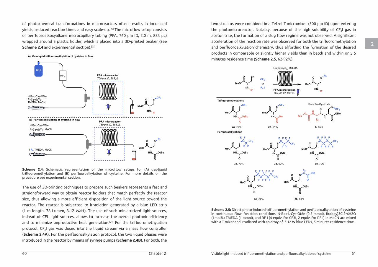
2
60 Chapter 2 Visible light-induced trifluoromethylation and perfluoroalkylation of cysteine 61
of photochemical transformations in microreactors often results in increased
yields, reduced reaction times and easy scale-up.[22] The microflow setup consists
of perfluoroalkoxyalkane microcapillary tubing (PFA, 760 μm ID, 2.0 m, 883 μL)
wrapped around a plastic holder, which is placed into a 3D-printed beaker (See
Scheme 2.4 and experimental section).[23]
Scheme 2.4: Schematic representation of the microflow setups for (A) gas-liquid trifluoromethylation and (B) perfluoroalkylation of cysteine. For more details on the procedure see experimental section.
The use of 3D-printing techniques to prepare such beakers represents a fast and
straightforward way to obtain reactor holders that match perfectly the reactor
size, thus allowing a more efficient disposition of the light source toward the
reactor. The reactor is subjected to irradiation generated by a blue LED strip
(1 m length, 78 Lumen, 3.12 Watt). The use of such miniaturized light sources,
instead of CFL light sources, allows to increase the overall photonic efficiency
and to minimize unproductive heat generation.[24] For the trifluoromethylation
protocol, CF3I gas was dosed into the liquid stream via a mass flow controller
(Scheme 2.4A). For the perfluoroalkylation protocol, the two liquid phases were
introduced in the reactor by means of syringe pumps (Scheme 2.4B). For both, the
PFA microreactor760 µm ID, 883 µL
MFC
CF3I
N-Boc-Cys-OMe,Ru(bpy)3Cl2TMEDA, MeCN
PFA microreactor760 µm ID, 883 µL
I-RF,TMEDA, MeCN
N-Boc-Cys-OMe,Ru(bpy)3Cl2, MeCN
RF
HN
O S
MeOOtBu
O
HN
O
MeO
R'
SCF3
A) Gas-liquid trifluoromethylation of cysteine in flow
B) Perfluoroalkylation of cysteine in flow
two streams were combined in a Tefzel T-micromixer (500 μm ID) upon entering
the photomicroreactor. Notably, because of the high solubility of CF3I gas in
acetonitrile, the formation of a slug flow regime was not observed. A significant
acceleration of the reaction rate was observed for both the trifluoromethylation
and perfluoroalkylation chemistry, thus affording the formation of the desired
products in comparable or slightly higher yields than in batch and within only 5
minutes residence time (Scheme 2.5, 62-92%).
Scheme 2.5: Direct photo-induced trifluoromethylation and perfluoroalkylation of cysteine in continuous flow. Reaction conditions: N-Boc-L-Cys-OMe (0.5 mmol), Ru(bpy)3Cl2•6H2O (1mol%) TMEDA (1 mmol), and RF-I (4 equiv. for CF3I, 2 equiv. for RF-I) in MeCN are mixed with a T-mixer and irradiated with an array of. 3.12 W blue LEDs, 5 minutes residence time.
PFA microreactor760 µm ID, 883 µL
2a, 79%
HN
O S
MeOOtBu
O
F F
FF
CF3
HN
O S
MeOOtBu
O
F F
FF
F F
CF3
HN
O S
MeOOtBu
O
F F
FF
F FCF3
F F
HN
O S
MeOOtBu
O
F F
FF
F F
F F
F F
CF3
F2C OEt
O
HN
O S
MeOOtBu
O
HN
O S
MeOOtBu
O
CF3
HN
O S
MeOMe
O
CF3O
HN
BnO
O
ONH
S
OMeCF3
tBu
Trifluoromethylations
Ru(bpy)3Cl2, TMEDA
HN
O SH
MeO
R' HN
O
MeO
R'
SRF
CF3IorRF-I
2b, 91% 5, 85%
Boc-Phe-Cys-OMe
Perfluoroalkylations
3a, 70% 3b, 92% 3c, 70%
3d, 62% 3h, 81%
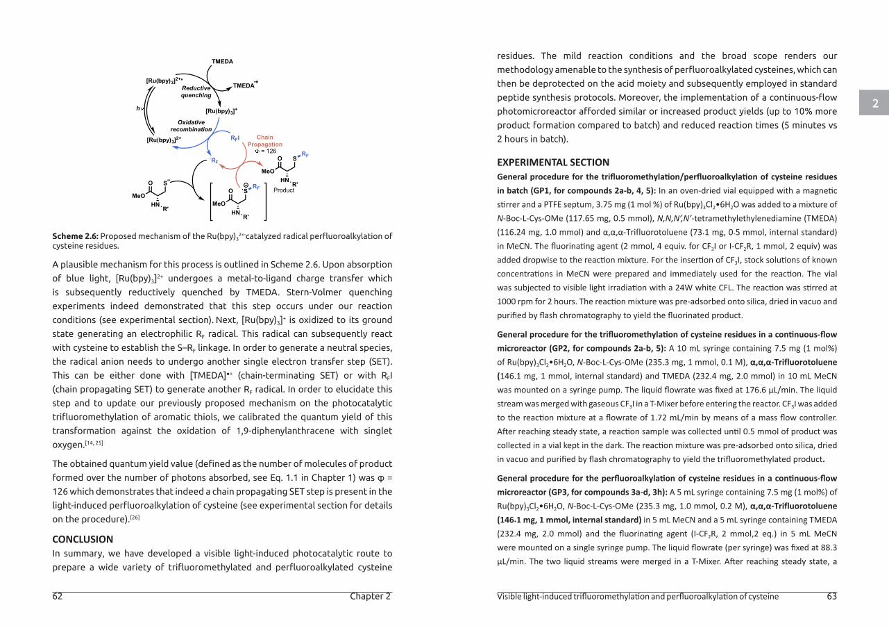
2
62 Chapter 2 Visible light-induced trifluoromethylation and perfluoroalkylation of cysteine 63
Scheme 2.6: Proposed mechanism of the Ru(bpy)32+-catalyzed radical perfluoroalkylation of
cysteine residues.
A plausible mechanism for this process is outlined in Scheme 2.6. Upon absorption
of blue light, [Ru(bpy)3]2+ undergoes a metal-to-ligand charge transfer which
is subsequently reductively quenched by TMEDA. Stern-Volmer quenching
experiments indeed demonstrated that this step occurs under our reaction
conditions (see experimental section). Next, [Ru(bpy)3]+ is oxidized to its ground
state generating an electrophilic RF radical. This radical can subsequently react
with cysteine to establish the S–RF linkage. In order to generate a neutral species,
the radical anion needs to undergo another single electron transfer step (SET).
This can be either done with [TMEDA]●+ (chain-terminating SET) or with RFI
(chain propagating SET) to generate another RF radical. In order to elucidate this
step and to update our previously proposed mechanism on the photocatalytic
trifluoromethylation of aromatic thiols, we calibrated the quantum yield of this
transformation against the oxidation of 1,9-diphenylanthracene with singlet
oxygen.[14, 25]
The obtained quantum yield value (defined as the number of molecules of product
formed over the number of photons absorbed, see Eq. 1.1 in Chapter 1) was φ =
126 which demonstrates that indeed a chain propagating SET step is present in the
light-induced perfluoroalkylation of cysteine (see experimental section for details
on the procedure).[26]
CONCLUSIONIn summary, we have developed a visible light-induced photocatalytic route to
prepare a wide variety of trifluoromethylated and perfluoroalkylated cysteine
[Ru(bpy)3]2+
[Ru(bpy)3]2+*
[Ru(bpy)3]+
TMEDA
TMEDAReductivequenching
Oxidativerecombination
h
ChainPropagation
= 126
RFI
RF
HN
O S
MeO
R'
RFHN
O S
MeO
R'
RF
Product
HN
O S
MeO
R'
residues. The mild reaction conditions and the broad scope renders our
methodology amenable to the synthesis of perfluoroalkylated cysteines, which can
then be deprotected on the acid moiety and subsequently employed in standard
peptide synthesis protocols. Moreover, the implementation of a continuous-flow
photomicroreactor afforded similar or increased product yields (up to 10% more
product formation compared to batch) and reduced reaction times (5 minutes vs
2 hours in batch).
EXPERIMENTAL SECTIONGeneral procedure for the trifluoromethylation/perfluoroalkylation of cysteine residues in batch (GP1, for compounds 2a-b, 4, 5): In an oven-dried vial equipped with a magnetic stirrer and a PTFE septum, 3.75 mg (1 mol %) of Ru(bpy)3Cl2•6H2O was added to a mixture of N-Boc-L-Cys-OMe (117.65 mg, 0.5 mmol), N,N,N’,N’-tetramethylethylenediamine (TMEDA) (116.24 mg, 1.0 mmol) and α,α,α-Trifluorotoluene (73.1 mg, 0.5 mmol, internal standard) in MeCN. The fluorinating agent (2 mmol, 4 equiv. for CF3I or I-CF2R, 1 mmol, 2 equiv) was added dropwise to the reaction mixture. For the insertion of CF3I, stock solutions of known concentrations in MeCN were prepared and immediately used for the reaction. The vial was subjected to visible light irradiation with a 24W white CFL. The reaction was stirred at 1000 rpm for 2 hours. The reaction mixture was pre-adsorbed onto silica, dried in vacuo and purified by flash chromatography to yield the fluorinated product.
General procedure for the trifluoromethylation of cysteine residues in a continuous-flow microreactor (GP2, for compounds 2a-b, 5): A 10 mL syringe containing 7.5 mg (1 mol%) of Ru(bpy)3Cl2•6H2O, N-Boc-L-Cys-OMe (235.3 mg, 1 mmol, 0.1 M), α,α,α-Trifluorotoluene (146.1 mg, 1 mmol, internal standard) and TMEDA (232.4 mg, 2.0 mmol) in 10 mL MeCN was mounted on a syringe pump. The liquid flowrate was fixed at 176.6 μL/min. The liquid stream was merged with gaseous CF3I in a T-Mixer before entering the reactor. CF3I was added to the reaction mixture at a flowrate of 1.72 mL/min by means of a mass flow controller. After reaching steady state, a reaction sample was collected until 0.5 mmol of product was collected in a vial kept in the dark. The reaction mixture was pre-adsorbed onto silica, dried in vacuo and purified by flash chromatography to yield the trifluoromethylated product.
General procedure for the perfluoroalkylation of cysteine residues in a continuous-flow microreactor (GP3, for compounds 3a-d, 3h): A 5 mL syringe containing 7.5 mg (1 mol%) of Ru(bpy)3Cl2•6H2O, N-Boc-L-Cys-OMe (235.3 mg, 1.0 mmol, 0.2 M), α,α,α-Trifluorotoluene (146.1 mg, 1 mmol, internal standard) in 5 mL MeCN and a 5 mL syringe containing TMEDA (232.4 mg, 2.0 mmol) and the fluorinating agent (I-CF2R, 2 mmol,2 eq.) in 5 mL MeCN were mounted on a single syringe pump. The liquid flowrate (per syringe) was fixed at 88.3 μL/min. The two liquid streams were merged in a T-Mixer. After reaching steady state, a
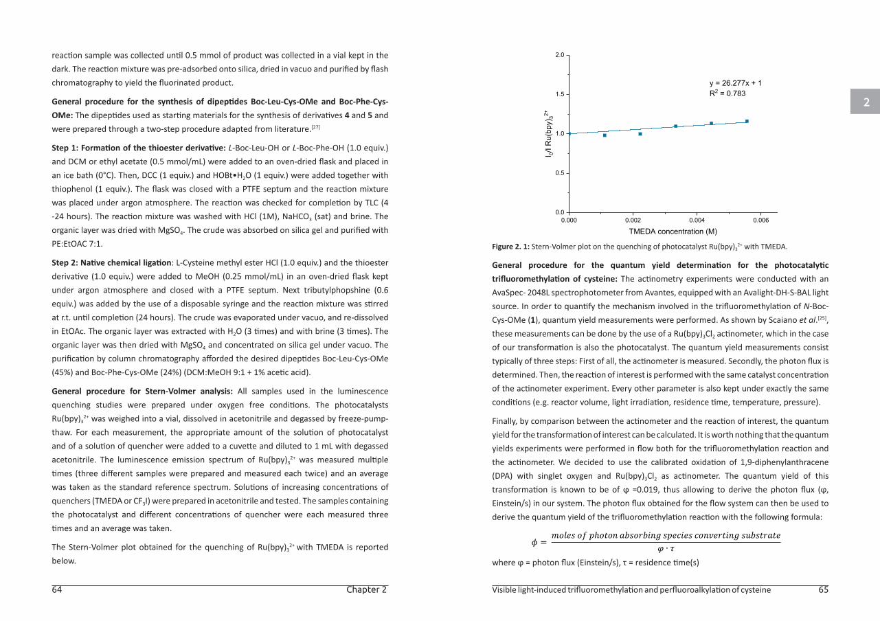
2
64 Chapter 2 Visible light-induced trifluoromethylation and perfluoroalkylation of cysteine 65
reaction sample was collected until 0.5 mmol of product was collected in a vial kept in the dark. The reaction mixture was pre-adsorbed onto silica, dried in vacuo and purified by flash chromatography to yield the fluorinated product.
General procedure for the synthesis of dipeptides Boc-Leu-Cys-OMe and Boc-Phe-Cys-OMe: The dipeptides used as starting materials for the synthesis of derivatives 4 and 5 and were prepared through a two-step procedure adapted from literature.[27]
Step 1: Formation of the thioester derivative: L-Boc-Leu-OH or L-Boc-Phe-OH (1.0 equiv.) and DCM or ethyl acetate (0.5 mmol/mL) were added to an oven-dried flask and placed in an ice bath (0°C). Then, DCC (1 equiv.) and HOBt•H2O (1 equiv.) were added together with thiophenol (1 equiv.). The flask was closed with a PTFE septum and the reaction mixture was placed under argon atmosphere. The reaction was checked for completion by TLC (4 -24 hours). The reaction mixture was washed with HCl (1M), NaHCO3 (sat) and brine. The organic layer was dried with MgSO4. The crude was absorbed on silica gel and purified with PE:EtOAC 7:1.
Step 2: Native chemical ligation: L-Cysteine methyl ester HCl (1.0 equiv.) and the thioester derivative (1.0 equiv.) were added to MeOH (0.25 mmol/mL) in an oven-dried flask kept under argon atmosphere and closed with a PTFE septum. Next tributylphopshine (0.6 equiv.) was added by the use of a disposable syringe and the reaction mixture was stirred at r.t. until completion (24 hours). The crude was evaporated under vacuo, and re-dissolved in EtOAc. The organic layer was extracted with H2O (3 times) and with brine (3 times). The organic layer was then dried with MgSO4 and concentrated on silica gel under vacuo. The purification by column chromatography afforded the desired dipeptides Boc-Leu-Cys-OMe (45%) and Boc-Phe-Cys-OMe (24%) (DCM:MeOH 9:1 + 1% acetic acid).
General procedure for Stern-Volmer analysis: All samples used in the luminescence quenching studies were prepared under oxygen free conditions. The photocatalysts Ru(bpy)3
2+ was weighed into a vial, dissolved in acetonitrile and degassed by freeze-pump-thaw. For each measurement, the appropriate amount of the solution of photocatalyst and of a solution of quencher were added to a cuvette and diluted to 1 mL with degassed acetonitrile. The luminescence emission spectrum of Ru(bpy)3
2+ was measured multiple times (three different samples were prepared and measured each twice) and an average was taken as the standard reference spectrum. Solutions of increasing concentrations of quenchers (TMEDA or CF3I) were prepared in acetonitrile and tested. The samples containing the photocatalyst and different concentrations of quencher were each measured three times and an average was taken.
The Stern-Volmer plot obtained for the quenching of Ru(bpy)32+ with TMEDA is reported
below.
Figure 2. 1: Stern-Volmer plot on the quenching of photocatalyst Ru(bpy)32+ with TMEDA.
General procedure for the quantum yield determination for the photocatalytic trifluoromethylation of cysteine: The actinometry experiments were conducted with an AvaSpec- 2048L spectrophotometer from Avantes, equipped with an Avalight-DH-S-BAL light source. In order to quantify the mechanism involved in the trifluoromethylation of N-Boc-Cys-OMe (1), quantum yield measurements were performed. As shown by Scaiano et al.[25], these measurements can be done by the use of a Ru(bpy)3Cl2 actinometer, which in the case of our transformation is also the photocatalyst. The quantum yield measurements consist typically of three steps: First of all, the actinometer is measured. Secondly, the photon flux is determined. Then, the reaction of interest is performed with the same catalyst concentration of the actinometer experiment. Every other parameter is also kept under exactly the same conditions (e.g. reactor volume, light irradiation, residence time, temperature, pressure).
Finally, by comparison between the actinometer and the reaction of interest, the quantum yield for the transformation of interest can be calculated. It is worth nothing that the quantum yields experiments were performed in flow both for the trifluoromethylation reaction and the actinometer. We decided to use the calibrated oxidation of 1,9-diphenylanthracene (DPA) with singlet oxygen and Ru(bpy)3Cl2 as actinometer. The quantum yield of this transformation is known to be of ϕ =0.019, thus allowing to derive the photon flux (ϕ, Einstein/s) in our system. The photon flux obtained for the flow system can then be used to derive the quantum yield of the trifluoromethylation reaction with the following formula:
where ϕ = photon flux (Einstein/s), τ = residence time(s)
𝜙𝜙𝜙𝜙 = 𝑚𝑚𝑚𝑚𝑚𝑚𝑚𝑚𝑚𝑚𝑚𝑚𝑚𝑚𝑚𝑚𝑚𝑚𝑚𝑚 𝑚𝑚𝑚𝑚𝑜𝑜𝑜𝑜 𝑝𝑝𝑝𝑝ℎ𝑚𝑚𝑚𝑚𝑜𝑜𝑜𝑜𝑚𝑚𝑚𝑚𝑜𝑜𝑜𝑜 𝑎𝑎𝑎𝑎𝑎𝑎𝑎𝑎𝑚𝑚𝑚𝑚𝑚𝑚𝑚𝑚𝑎𝑎𝑎𝑎𝑎𝑎𝑎𝑎𝑎𝑎𝑎𝑎𝑜𝑜𝑜𝑜𝑎𝑎𝑎𝑎 𝑚𝑚𝑚𝑚𝑝𝑝𝑝𝑝𝑚𝑚𝑚𝑚𝑠𝑠𝑠𝑠𝑎𝑎𝑎𝑎𝑚𝑚𝑚𝑚𝑚𝑚𝑚𝑚 𝑠𝑠𝑠𝑠𝑚𝑚𝑚𝑚𝑜𝑜𝑜𝑜𝑐𝑐𝑐𝑐𝑚𝑚𝑚𝑚𝑎𝑎𝑎𝑎𝑜𝑜𝑜𝑜𝑎𝑎𝑎𝑎𝑜𝑜𝑜𝑜𝑎𝑎𝑎𝑎 𝑚𝑚𝑚𝑚𝑠𝑠𝑠𝑠𝑎𝑎𝑎𝑎𝑚𝑚𝑚𝑚𝑜𝑜𝑜𝑜𝑎𝑎𝑎𝑎𝑎𝑎𝑎𝑎𝑜𝑜𝑜𝑜𝑚𝑚𝑚𝑚
𝜑𝜑𝜑𝜑 ∙ 𝜏𝜏𝜏𝜏
2
66 Chapter 2 Visible light-induced trifluoromethylation and perfluoroalkylation of cysteine 67
COMPOUND CHARACTERIZATION
Methyl N-(tert-butoxycarbonyl)-S-(trifluoromethyl)-L-cysteinate (2a)[12] was made according to GP1 on a 0.5 mmol scale. The crude product was purified by flash chromatography (petroleum ether: ethyl acetate 100:0 to 90:10) yielding 124.4 mg (0.41 mmol, 82%) of derivative 2a as a white solid (Mp: 67.6-67.9 °C). The reaction according to GP2 on a 0.5 mmol scale afforded. 120 mg (0.39 mmol, 79 %) of product 2a after 5 minutes residence time. 1H NMR (399 MHz, Chloroform-d) δ 5.35 (s, 1H), 4.62 (s, 1H), 3.79 (s, 3H), 3.58 – 3.23 (m, 2H), 1.45 (s, 9H). 13C NMR (101 MHz, Chloroform-d) δ 170.1, 154.9, 130.5 (q, J = 306.4 Hz), 80.6, 53.0, 52.9, 32.1, 28.2. 19F NMR (376 MHz, Chloroform-d) δ -41.0 HRMS (ESI) calculated for C5H9F3NO2S [M-Boc+H]+: 204.0306; found: 204.0308. IR (ATR, cm-1): 3358, 3000, 1724, 1674, 1519, 1369, 1342, 1328, 1292, 1251, 1161, 1145.
Methyl N-acetyl-S-(trifluoromethyl)-L-cysteinate (2b)[11] was made according to GP1 on a 0.5 mmol scale. The crude product was purified by flash chromatography (petroleum ether: ethyl ether 1:1) yielding 110.3 mg (0.45 mmol, 90%) of derivative 2b as a white solid (Mp: 68.6-69.4 °C). The reaction according to GP2 on a 0.5 mmol scale afforded 111.5 mg (0.46 mmol, 91%) of product 2b. 1H NMR (400 MHz, Chloroform-d) δ 6.72 (s, 1H), 5.01 – 4.60 (m, 1H), 3.74 (s, 3H), 3.59 – 3.10 (m, 2H), 2.00 (s, 3H13C NMR (101 MHz, Chloroform-d) δ 170.3, 170.1, 130.5 (q, J = 306.4 Hz), 53.0, 51.9, 31.6, 22.8, 15.2.19F NMR (376 MHz, Chloroform-d) δ -41.1. HRMS (ESI) calculated for C7H11F3NO3S [M+H]+: 246.0412; found: 246.0401. IR (ATR, cm-1): 3317, 2958, 1741, 1734, 1641, 1537, 1340, 1255, 1105, 1039.
Methyl N-(tert-butoxycarbonyl)-S-(perfluoropropyl)-L-cysteinate (3a) was made according to GP1 on a 0.5 mmol scale. The crude product was purified by flash chromatography (petroleum ether: ethyl acetate 100:0 to 90:10) yielding 121 mg (0.3 mmol, 60 %) of derivative 3a as yellow oil. The reaction according to GP3 on a 0.5 mmol scale afforded 141.2 mg (0.35 mmol, 70 %) of compound 3a.1H NMR (399 MHz, Chloroform-d) δ 5.37 (s, 1H), 4.61 (s, 1H), 3.78 (s, 3H), 3.60 – 3.28 (m, 2H), 1.44 (s, 9H). 13C NMR (100 MHz, Chloroform-d) δ 170.2, 155.1, 128.0 – 120.8 (m), 117.4 (dt, J = 288.1, 33.3 Hz), 114.0 – 106.9 (m), 80.7, 53.2, 52.9, 30.9, 28.2. 19F NMR (376 MHz, Chloroform-d) δ -76.30 – -82.31 (m), -84.76 – -89.66 (m), -124.08. HRMS (ESI) calculated for C7H9F7NO2S+ [M-Boc+H]+: 304.0237; found: 304.0238: 254. IR (ATR, cm-1): 3367, 2982, 1724, 1518, 1336, 1180, 1161, 1112.
Methyl N-(tert-butoxycarbonyl)-S-(perfluorobutyl)-L-cysteinate (3b) was made according to GP1 on a 0.5 mmol scale. The crude product was purified by flash chromatography (petroleum ether: ethyl acetate 100:0 to 90:10) yielding 190.2 mg (0.42 mmol, 84%) of derivative 3b as yellow oil. The reaction according to GP3 on a 0.5 mmol scale afforded 209.3.mg (0.46 mmol, 92 %) of compound 3b.1H NMR (399 MHz, Chloroform-d) δ 5.49 (s, 1H), 4.58 (s, 1H), 3.74 (s, 3H), 3.56 – 3.25 (m, 2H), 1.40 (s, 9H). 13C NMR (100 MHz, Chloroform-d) δ 170.2,
155.1, 127.8 – 123.4 (m), 122.7 – 120.5 (m), 117.4 (dt, J = 288.1, 33.3 Hz), 114.6 – 105.3 (m), 80.7, 53.2, 52.9, 30.9, 28.2. 19F NMR (376 MHz, Chloroform-d) δ -81.39 (t, J = 9.8 Hz), -85.67 – -88.16 (m), -119.94 – -121.26 (m), -125.32 – -126.23 (m). HRMS (ESI) calculated for C8H9F9NO2S+ [M-Boc+H]+: 354.0205; found: 354.0206. IR (ATR, cm-1): 3370, 2997, 1724, 1681, 1518, 1348, 1225, 1198, 1163, 1136.
Methyl N-(tert-butoxycarbonyl)-S-(perfluoropentyl)-L-cysteinate (3c) was made according to GP1 on a 0.5 mmol scale. The crude product was purified by flash chromatography (petroleum ether: ethyl acetate 100:0 to 90:10) yielding 178.7 mg (0.36 mmol, 71%) of derivative 3c as yellow oil. The reaction according to GP3 on a 0.5 mmol scale afforded 176.1.mg (0.35 mmol, 70%) of compound 3c. 1H NMR (399 MHz, Chloroform-d) δ 5.37 (s, 1H), 4.63 (s, 1H), 3.79 (s, 3H), 3.61 – 3.27 (m, 2H), 1.44 (s, 9H). 13C NMR (100 MHz, Chloroform-d) δ 170.0, 154.8, 127.8 – 126.3 (m), 124.6 – 123.5 (m), 122.3 – 120.3 (m), 119.3 – 117.9 (m), 115.9 (d, J = 33.1 Hz), 80.6, 53.0, 52.9, 30.9, 28.1. 19F NMR (376 MHz, Chloroform-d) δ -80.47 – -81.14 (m), -85.48 – -87.66 (m), -119.18 – -120.38 (m), -121.60 – -122.76 (m), -125.63 – -127.13 (m). HRMS (ESI) calculated for C9H9F11NO2S+ [M-Boc+H]+: 404,0173; found: 404,0171. IR (ATR, cm-1): 3371, 2997, 2949, 1726, 1680, 1518, 1288, 1223, 1099.
Methyl N-(tert-butoxycarbonyl)-S-(perfluorohexyl)-L-cysteinate (3d) was made according to GP1 on a 0.5 mmol scale. The crude product was purified by flash chromatography (petroleum ether: ethyl acetate 100:0 to 90:10) yielding 171.4 mg (0.31 mmol, 62%) of derivative 3d as yellow oil. The reaction according to GP3 on a 0.5 mmol scale afforded 171.6 mg (0.31 mmol, 62%) of compound 3d. 1H NMR (399 MHz, Chloroform-d) δ 5.40 (s, 1H), 4.62 (s, 1H), 3.78 (s, 3H), 3.55 – 3.25 (m, 2H), 1.43 (s, 9H 13C NMR (100 MHz, Chloroform-d) δ 170.0, 154.8, 125.5 (dt, J = 292.5, 34.1 Hz), 121.6 – 120.8 (m), 117.1 (dt, J = 288.5, 33.2 Hz), 114.4 – 112.2 (m), 111.6 – 109.6 (m), 109.2 – 107.1 (m), 80.5, 53.0, 52.8, 30.8, 28.1. 19F NMR (376 MHz, Chloroform-d) δ -80.11 – -81.65 (m), -85.12 – -88.04 (m), -119.78, -121.51, -122.94, -125.67 – -127.15 (m). HRMS (ESI) calculated for C10H9F13NO2S+
[M-Boc+H]+: 454,0141; found: 454.0153. IR (ATR, cm-1): 3379, 2980, 2951, 1728, 1695, 1682, 1518, 1317, 1199, 1188, 1163, 1147.
Methyl N-(tert-butoxycarbonyl)-S-(perfluoroheptyl)-L-cysteinate (3e) was made according to GP1 on a 0.5 mmol scale. The crude product was purified by flash chromatography (petroleum ether : diethylether 16:1 to 8:1 )yielding 269.5 mg (0.44 mmol, 90 %) of derivative 3e as yellow oil. 1H NMR (399 MHz, Chloroform-d) δ 5.42 (s, 1H), 4.62 (s, 1H), 3.77 (s, 3H), 3.61 – 3.27 (m, 2H), 1.43 (s, 9H). 13C NMR (100 MHz, Chloroform-d) δ 170.2, 155.1, 127.8 – 123.6 (m), 122.2 – 120.3 (m), 117.3 (dt, J = 288.5, 33.0 Hz), 114.5 – 112.4 (m), 112.2 – 109.9 (m), 109.2 – 107.2 (m), 106.7 – 104.5 (m), 80.7, 53.2, 53.0, 31.0, 28.3. 19F NMR (376 MHz, Chloroform-d) δ -81.07 (t, J = 10.0 Hz), -84.97 – -88.54 (m), -119.78, -121.39, -122.18, -122.93, -126.00 – -126.69 (m). HRMS (ESI) calculated for C11H9F15NO2S+
2
68 Chapter 2 Visible light-induced trifluoromethylation and perfluoroalkylation of cysteine 69
[M-Boc+H]+: 504,0109; found: 504,0114. IR (ATR, cm-1): 3377, 2991, 1728, 1693, 1681, 1518, 1321, 1230, 1193, 1149.
Methyl N-(tert-butoxycarbonyl)-S-(perfluorooctyl)-L-cysteinate (3f) was made according to GP1 on a 0.5 mmol scale. The crude product was purified by flash chromatography (petroleum ether :ether 10:1 to 6:1) yielding 218.9 mg (0.34 mmol, 67%) of derivative 3f as yellow oil. 1H NMR (399 MHz, Chloroform-d) δ 5.40 (s, 1H), 4.63 (s, 1H), 3.78 (s, 3H), 3.56 – 3.30 (m, 2H), 1.43 (s, 9H). 13C NMR (100 MHz, Chloroform-d) δ 170.2, 155.0, 127.4 (d, J = 33.4 Hz), 124.3 (t, J = 33.9 Hz), 119.5 – 118.2 (m), 118.1 – 117.2 (m), 115.8 (t, J = 33.4 Hz), 112.0 – 109.8 (m), 109.5 – 107.0 (m), 80.8, 53.2, 53.1, 31.1, 28.3.19F NMR (376 MHz, Chloroform-d) δ -81.02 (t, J = 10.0 Hz), -84.55 – -89.24 (m), -119.59 – -119.88 (m), -121.20 – -121.46 (m), -121.80 – -122.27 (m), -122.74 – -123.14 (m), -126.25 – -126.46 (m). HRMS (ESI) calculated for C12H9F17NO2S+ [M-Boc+H]+: 554,0077; found: 554.0076. IR (ATR, cm-1): 3383, 2991, 1695, 1681, 1516, 1369, 1195, 1118, 1082.
Methyl N-(tert-butoxycarbonyl)-S-(perfluorodecyl)-L-cysteinate (3g) was made according to GP1 on a 0.5 mmol scale. The crude product was purified by flash chromatography (petroleum ether : ether 12:1 to 8:1) yielding 225.9 mg (0.3 mmol, 60 %) of derivative 3g as a white solid (Mp: 65.5-67.1 °C). 1H NMR (399 MHz, Chloroform-d) δ 5.38 (s, 1H), 4.64 (s, 1H), 3.79 (s, 3H), 3.65 – 3.22 (m, 2H), 1.44 (s, 9H). 13C NMR (100 MHz, Chloroform-d) δ 170.2, 155.0, 127.7 – 127.0 (m), 126.3 – 125.5 (m), 124.9 – 123.9 (m), 122.0 – 121.1 (m), 119.4 – 118.0 (m), 116.5 – 115.1 (m), 114.4 – 113.0 (m), 111.9 – 109.7 (m), 109.3 – 106.8 (m), 80.8, 53.2, 53.1, 31.1, 28.3. 19F NMR (376 MHz, Chloroform-d) δ -80.48 – -81.23 (m), -85.58 – -87.69 (m), -119.21 – -119.96 (m), -120.84 – -121.55 (m), -121.55 – -122.26 (m), -122.62 – -123.05 (m), -125.67 – -126.94 (m). HRMS (ESI) calculated for C14H9F21NO2S+ [M-Boc+H]+: 654,0013; found: 654,0019. IR (ATR, cm-1): 3383, 2982, 1728, 1695, 1684, 1516, 1198, 1141.
Methyl N-(tert-butoxycarbonyl)-S-(2-ethoxy-1,1-difluoro-2-oxoethyl)-L-cysteinate (3h) was made according to GP1 on a 0.5 mmol scale. The crude product was purified by flash chromatography (petroleum ether: ethyl acetate 100:0 to 90:10) yielding 134.2 mg (0.38 mmol, 75%) of derivative 3h as yellow oil. The reaction according to GP3 on a 0.5 mmol scale afforded 144.7.mg (0.40 mmol, 81%) of compound 3h. 1H NMR (400 MHz, Chloroform-d) δ 5.36 (s, 1H), 4.55 (s, 1H), 4.31 (q, J = 7.1 Hz, 2H), 3.73 (s, 3H), 3.48 – 3.18 (m, 2H), 1.40 (s, 9H), 1.32 (t, J = 7.1 Hz, 3H).13C NMR (101 MHz, Chloroform-d) δ = 170.4, 161.4 (t, J=32.6), 154.9, 120.0 (t, J=287.4), 80.4, 63.8, 53.0, 52.8, 30.9, 28.2, 13.8. 19F NMR (376 MHz, Chloroform-d) δ = -80.9 – -82.4 (m). HRMS (ESI) calculated for C8H14F2NO4S+ [M-Boc+H]+: 258,0612; found: 258,0616. IR (ATR, cm-1): 3387, 2980, 1755, 1714, 1504, 1247, 1161, 1010.
Methyl N-((tert-butoxycarbonyl)-L-leucyl)-S-(trifluoromethyl)-L-cysteinate (4) was made according to GP1 on a 0.50 mmol scale. The crude product was purified by flash
chromatography (petroleum ether: ether: 6:1 to 3:1) yielding 117 mg (0.28 mmol, 56%) of derivative 4 as a white solid (Mp: 78.8-79.3 °C). 1H NMR (400 MHz, Chloroform-d) δ 7.22 (s, 1H), 5.00 (s, 1H), 4.80 (q, J = 5.3 Hz, 1H), 4.14 (s, 1H), 3.75 (s, 3H), 3.52 – 3.24 (m, 2H), 1.74 – 1.58 (m, 2H), 1.51 – 1.44 (m, 1H), 1.42 (s, 9H), 0.91 (t, J = 6.8 Hz, 6H). 13C NMR (101 MHz, Chloroform-d) δ 172.8, 169.7, 155.6, 130.5 (q, J = 306.4 Hz), 80.2, 53.1, 52.9, 51.8, 40.8, 31.4, 28.2, 24.7, 22.8, 21.9. 19F NMR (376 MHz, Chloroform-d) δ -41.03. HRMS (ESI) calculated for C16H27F3N2NaO5S+ [M+Na]+: 439,1485; found: 439,1487. IR (ATR, cm-1): 3334, 2958, 1755, 1686, 1654, 1514, 1367, 1153, 1103.
Methyl N-((tert-butoxycarbonyl)-L-phenylalanyl)-S-(trifluoromethyl)-L-cysteinate (5)[6c] was made according to GP1 on a 0.50 mmol scale. The crude product was purified by flash chromatography (petroleum ether: ethyl ether 50:50 to 0:100) yielding 211.5 mg (0.47 mmol, 94%) of derivative 5 as a white solid (Mp: 112.2-112.9 °C). The reaction according to GP2 on a 0.5 mmol scale afforded 191.3.mg (0.43 mmol, 85%) of compound 5. 1H NMR (400 MHz, Chloroform-d) δ 7.41 – 7.16 (m, 5H), 6.83 (s, 1H), 4.94 (s, 1H), 4.82 (s, 1H), 4.42 (s, 1H), 3.79 (s, 3H), 3.58 – 3.27 (m, 2H), 3.20 – 3.04 (m, 2H), 1.45 (s, 9H). 13C NMR (101 MHz, Chloroform-d) δ 171.5, 169.5, 155.5, 141.8 – 129.7 (m), 129.4, 129.0, 128.9, 127.2, 80.7, 55.8, 53.1, 52.0, 38.0, 31.6 (d, J = 2.2 Hz), 28.4. 19F NMR (376 MHz, Chloroform-d) δ -40.9. HRMS (ESI) calculated for C19H25F3N2NaO5S+ [M+Na]+: 473,1329; found: 473,1323. IR (ATR, cm-1): 3325, 2972, 1741, 1681, 1666, 1516, 1439, 1298, 1220, 1153.
ASSOCIATED CONTENTThe Supporting Information for this article is available free of charge on the ACS Publications website at DOI: 10.1021/acs.joc.6b01031
2
70 Chapter 2 Visible light-induced trifluoromethylation and perfluoroalkylation of cysteine 71
REFERENCES:[1] a) Y. Zhou, J. Wang, Z. Gu, S. Wang, W. Zhu, J. L. Aceña, V. A. Soloshonok, K. Izawa, H.
Liu, Chem. Rev. 2016, 116, 422-518; b) S. Purser, P. R. Moore, S. Swallow, V. Gouverneur, Chem. Soc. Rev. 2008, 37, 320-330.
[2] a) H. Chen, S. Viel, F. Ziarelli, L. Peng, Chem. Soc. Rev. 2013, 42, 7971-7982; b) E. N. G. Marsh, Y. Suzuki, ACS Chem. Biol. 2014, 9, 1242-1250.
[3] a) S. Mizuta, I. S. R. Stenhagen, M. O’Duill, J. Wolstenhulme, A. K. Kirjavainen, S. J. Forsback, M. Tredwell, G. Sandford, P. R. Moore, M. Huiban, S. K. Luthra, J. Passchier, O. Solin, V. Gouverneur, Org. Lett. 2013, 15, 2648-2651; b) M. Huiban, M. Tredwell, S. Mizuta, Z. Wan, X. Zhang, T. L. Collier, V. Gouverneur, J. Passchier, Nat. Chem. 2013, 5, 941-944; c) T. Khotavivattana, S. Verhoog, M. Tredwell, L. Pfeifer, S. Calderwood, K. Wheelhouse, T. Lee Collier, V. Gouverneur, Angew. Chem., Int. Ed. 2015, 54, 9991-9995; d) A. F. Brooks, J. J. Topczewski, N. Ichiishi, M. S. Sanford, P. J. H. Scott, Chem. Sci. 2014, 5, 4545-4553.
[4] a) M. R. Seyedsayamdost, C. S. Yee, J. Stubbe, Nat. Protoc. 2007, 2, 1225-1235; b) L. Merkel, N. Budisa, Org. Biomol. Chem. 2012, 10, 7241-7261.
[5] a) N. C. Yoder, K. Kumar, Chem. Soc. Rev. 2002, 31, 335-341; b) E. N. G. Marsh, Acc. Chem. Res. 2014, 47, 2878-2886; c) A. M. Spokoyny, Y. Zou, J. J. Ling, H. Yu, Y.-S. Lin, B. L. Pentelute, J. Am. Chem. Soc. 2013, 135, 5946-5949.
[6] a) X.-L. Qiu, F.-L. Qing, Eur. J. Org. Chem. 2011, 2011, 3261-3278; b) J. L. Aceña, A. E. Sorochinsky, V. A. Soloshonok, Synthesis 2012, 44, 1591-1602; c) S. Capone, I. Kieltschb, O. Flögela, G. Lelaisa, A. Togni, D. Seebach, Helv. Chim. Acta 2008, 91, 2035-2056.
[7] A. Talla, B. Driessen, N. J. W. Straathof, L.-G. Milroy, L. Brunsveld, V. Hessel, T. Noël, Adv. Synth. Catal. 2015, 357, 2180-2186.
[8] a) S. B. Gunnoo, A. Madder, ChemBioChem 2016, 17, 529-553; b) C. D. Spicer, B. G. Davis, Nat. Commun. 2014, 5, 4740.
[9] V. N. Boiko, Beilstein J. Org. Chem. 2010, 6, 880-921.
[10] V. Soloshonok, V. Kukhar, Y. Pustovit, V. Nazaretian, Synlett 1992, 8, 657-658.
[11] B. Langlois, D. Montègre, N. Roidot, J. Fluorine Chem. 1994, 68, 63-66.
[12] I. Kieltsch, P. Eisenberger, A. Togni, Angew. Chem., Int. Ed. 2007, 46, 754-757.
[13] a) N. J. W. Straathof, H. P. L. Gemoets, X. Wang, J. C. Schouten, V. Hessel, T. Noël, ChemSusChem 2014, 7, 1612-1617; b) N. Straathof, D. Osch, A. Schouten, X. Wang, J. Schouten, V. Hessel, T. Noël, J. Flow Chem. 2015, 4, 12-17; c) E. Kim, S. Choi, H. Kim, E. J. Cho, Chem. - Eur. J. 2013, 19, 6209-6212; d) N. Iqbal, S. Choi, E. Kim, E. J. Cho, J. Org. Chem. 2012, 77, 11383-11387; e) P. V. Pham, D. A. Nagib, D. W. C. MacMillan, Angew. Chem., Int. Ed. 2011, 50, 6119-6122; f) D. A. Nagib, M. E. Scott, D. W. C. MacMillan, J. Am. Chem. Soc. 2009, 131, 10875-10877; g) Y. Ye, M. S. Sanford, J. Am. Chem. Soc. 2012, 134, 9034-9037; h) F. Sladojevich, E. McNeill, J. Börgel, S.-L. Zheng, T. Ritter, Angew. Chem., Int. Ed. 2015, 54, 3712-3716.
[14] N. J. W. Straathof, B. J. P. Tegelbeckers, V. Hessel, X. Wang, T. Noël, Chem. Sci. 2014, 5, 4768-4773.
[15] E. N. Okafo, E. Whittle, Int. J. Chem. Kinet. 1975, 7, 273-285.
[16] M. Salwiczek, E. K. Nyakatura, U. I. M. Gerling, S. Ye, B. Koksch, Chem. Soc. Rev. 2012, 41, 2135-2171.
[17] B. E. Smart, 1994, DOI: 10.1007/978-1-4899-1202-2_3, 57-88.
[18] T. M. Miller, B. Bederson, 1978, 13, 1-55.
[19] J. C. Biffinger, H. W. Kim, S. G. DiMagno, ChemBioChem 2004, 5, 622-627.
[20] a) W. Zhang, Chem. Rev. 2004, 104, 2531-2556; b) K.-S. Ko, F. A. Jaipuri, N. L. Pohl, J. Am. Chem. Soc. 2005, 127, 13162-13163; c) R. L. Nicholson, M. L. Ladlow, D. R. Spring, Chem. Commun. (Cambridge, U. K.) 2007, 38, 3906-3908; d) A. Studer, S. Hadida, R. Ferritto, S.-Y. Kim, P. Jeger, P. Wipf, D. P. Curran, Science 1997, 275, 823-826.
[21] a) D. Cambié, C. Bottecchia, N. J. W. Straathof, V. Hessel, T. Noël, Chem. Rev. 2016, 116, 10276-10341; b) T. H. Rehm, Chem. Eng. Technol. 2016, 39, 66-80; c) J. P. Knowles, L. D. Elliott, K. I. Booker-Milburn, Beilstein J. Org. Chem. 2012, 8, 2025-2052; d) M. B. Plutschack, C. A. Correia, P. H. Seeberger, K. Gilmore, in Top. Organomet. Chem., 2016, 57, 43-76.
[22] a) Y. Su, N. J. W. Straathof, V. Hessel, T. Noël, Chem. - Eur. J. 2014, 20, 10562-10589; b) Y. Su, K. Kuijpers, V. Hessel, T. Noël, React. Chem. Eng. 2016, 1, 73-81; c) K. Loubière, M. Oelgemöller, T. Aillet, O. Dechy-Cabaret, L. Prat, Chem. Eng. Process. 2016, 104, 120-132.
[23] N. J. W. Straathof, Y. Su, V. Hessel, T. Noël, Nat. Protoc. 2015, 11, 10-21.
[24] Y. Su, A. Talla, V. Hessel, T. Noel, Chem. Eng. Technol. 2015, 38, 1733-1742.
[25] S. P. Pitre, C. D. McTiernan, W. Vine, R. DiPucchio, M. Grenier, J. C. Scaiano, Sci. Rep. 2015, 5, 16397.
[26] M. A. Cismesia, T. P. Yoon, Chem. Sci. 2015, 6, 5426-5434.
[27] L. Markey, S. Giordani, E. M. Scanlan, J. Org. Chem. 2013, 78, 4270-4277.
CHAPTER 3
Batch and flow synthesis of disulfides by visible light induced TiO2 photocatalysis
This chapter is based on:
Bottecchia, C.; Erdmann, N.; Tijssen, P.; Milroy, L. G.; Brunsveld, L.; Hessel, V.; Noël, T., ChemSusChem, 2016, 9, 1781-1785
3
74 Chapter 3 Batch and flow synthesis of disulfides by visible light induced TiO2 photocatalysis 75
ABSTRACT
In this chapter, a mild and practical method for the preparation of disulfides via
visible light induced photocatalytic aerobic oxidation of thiols is reported. The
method involves the use of TiO2 as a heterogeneous photocatalyst. The catalyst’s
high stability and recyclability makes this method highly practical. The reaction
can be substantially accelerated in a continuous-flow packed-bed reactor, which
enables a safe and reliable scale-up of the reaction conditions. The batch and
flow protocol described herein can be applied to a diverse set of thiol substrates
for the preparation of homo- and hetero-dimerized disulfides. Furthermore,
biocompatible reaction conditions (room temperature, visible light, neutral buffer
solution, no additional base) have been developed, which permits the rapid and
chemoselective modification of densely functionalized peptide substrates without
recourse to complex purification steps.
INTRODUCTION
Several synthetic approaches reported in the literature suggest viable strategies
for the formation of symmetrical and unsymmetrical disulfides.[1] In Nature,
disulfides play a pivotal role in protein folding and oligomerization.[2] Disulfides are
also fundamental to the production of many fine chemicals and pharmaceuticals, as
well as vulcanizing reagents for industrial-scale rubber production.[3] Nevertheless,
traditional synthetic methods might require the use of harsh reaction conditions,
such as stoichiometric amounts of metal oxides or peroxides. More recently, milder
and greener approaches have been developed, including aerobic oxidation of thiols
in presence of molecular oxygen or air, catalyzed by transition metal complexes.[4] Owing to the prevalence of disulfides in proteins, a number of biocompatible
and bio-orthogonal methodologies have also been developed.[5] In such cases, S–S
bond formation serves as a controlled trigger for oxidative folding or as a method
to enable bioconjugation.[6] The redox-sensitive nature of disulfide bonds also
renders them viable candidates for drug delivery systems.[7] Nevertheless, rapid,
straightforward and biocompatible strategies are still in demand to obviate the
need for long reaction times and activating agents (e.g. Ellmann’s reagent or
methanethiosulfonate reagents).[7c, 8]
We recently reported a photocatalytic approach to symmetrical disulfides catalyzed
by the organic dye Eosin Y.[9] Despite the mild reaction conditions and fast reaction
times of our approach, the use of Eosin Y as a homogeneous photocatalyst still
necessitates an additional purification step to recover catalyst and isolate the
target disulfide. In peptide and protein modification, purification steps are
undesired and often problematic, especially for delicate proteins that are prone
to denature. Furthermore, the use of a transition-metal complex as homogeneous
catalyst might lead to bio-incompatibility issues, since these catalysts tend to give
undesired binding interactions.[6a, 10]
In our efforts to develop efficient synthetic tools for chemical biology purposes, our
attention was drawn to the use of TiO2 as a cheap and recyclable photocatalyst of
aerobic S–S bond formation.[11] To date, the main application of TiO2 photocatalysis
has been in the water treatment industry,[12] while its use for organic synthesis
remains scarce.[11, 13] In light of the high energy band-gap of nanoscale TiO2 (3.2 eV
for the anatase form), its photocatalytic activity is typically associated with UV-
light irradiation.[14] However, given the incompatibility of UV light to peptides and
proteins, [15] we reasoned that visible-light photoredox catalysis would be better
suited to chemical biology applications owing to the milder reaction conditions
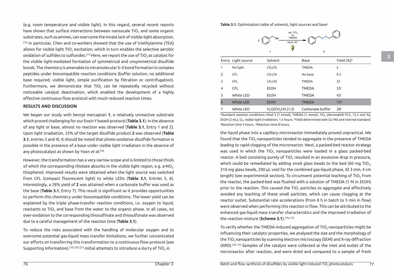
3
76 Chapter 3 Batch and flow synthesis of disulfides by visible light induced TiO2 photocatalysis 77
(e.g. room temperature and visible light). In this regard, several recent reports
have shown that surface interactions between nanoscale TiO2 and some organic
substrates, such as amines, can overcome the innate lack of visible-light absorption.[16] In particular, Chen and co-workers showed that the use of triethylamine (TEA)
allows for visible light TiO2 excitation, which in turn enables the selective aerobic
oxidation of sulfides to sulfoxides.[17] Here, we report the use of TiO2 as catalyst for
the visible light-mediated formation of symmetrical and unsymmetrical disulfide
bonds. The chemistry is amenable to intramolecular S–S bond formation in complex
peptides under biocompatible reaction conditions (buffer solution, no additional
base required, visible light, simple purification by filtration or centrifugation).
Furthermore, we demonstrate that TiO2 can be repeatedly recycled without
noticeable catalyst deactivation, which enabled the development of a highly
effective continuous-flow protocol with much reduced reaction times.
RESULTS AND DISCUSSION
We began our study with benzyl mercaptan 1, a relatively unreactive substrate
which proved challenging for our Eosin Y based-protocol (Table 3.1). In the absence
of any light or base, almost no reaction was observed (Table 3.1, Entry 1 and 2).
Upon light irradiation, 33% of the target disulfide product 2 was observed (Table
3.1, entries 3 and 4). It should be noted that photo-oxidative disulfide formation is
possible in the presence of a base under visible light irradiation in the absence of
any photocatalyst as shown by Yoon et al.[18]
However, the transformation has a very narrow scope and is limited to those thiols
of which the corresponding thiolate absorbs in the visible light region, e.g. p-NO2-
thiophenol. Improved results were obtained when the light source was switched
from CFL (compact fluorescent light) to white LEDs (Table 3.1, Entries 5, 6).
Interestingly, a 28% yield of 2 was attained when a carbonate buffer was used as
the base (Table 3.1, Entry 7). This result is significant as it provides opportunities
to perform this chemistry under biocompatible conditions. The lower yield can be
explained by the triple phase-transfer reaction conditions, i.e. oxygen to liquid,
reactants to TiO2 and base from the water to the organic phase. In all cases, no
over-oxidation to the corresponding thiosulfinate and thiosulfonate was observed
due to a careful management of the reaction time (Table 3.1).
To reduce the risks associated with the handling of molecular oxygen and to
overcome potential gas-liquid mass transfer limitations, we further concentrated
our efforts on transferring this transformation to a continuous-flow protocol (see
Supporting Information).[19] [20] [21] Initial attempts to introduce a slurry of TiO2 in
Table 3.1: Optimization table of solvents, light sources and basea
Entry Light source Solvent Base Yield (%)b
1 No light CH3CN TMEDA 2
2 CFL CH3CN No base 0.5
3 CFL CH3CN TMEDA 32
4 CFL EtOH TMEDA 33c
5 White LED EtOH TMEDA 43c
6 White LED EtOH TMEDA 75d
7 White LED H2O/CH3CN (1:3) Carbonate buffer 28c
aStandard reaction conditions: thiol 1 (1 mmol), TMEDA (1 mmol), TiO2 (Aeroxide® P25, 12.5 mol %),
EtOH (2 mL), O2, visible light irradiation, 1.5 hours. bYield determined with GC-MS and internal standard. cReaction time 5 hours. dReaction time 8 hours.
the liquid phase into a capillary microreactor immediately proved unpractical. We
found that the TiO2 nanoparticles tended to aggregate in the presence of TMEDA
leading to rapid clogging of the microreactor. Next, a packed-bed reactor strategy
was used in which the TiO2 nanoparticles were loaded in a glass packed-bed
reactor. A bed consisting purely of TiO2 resulted in an excessive drop in pressure,
which could be remediated by adding small glass beads to the bed (60 mg TiO2,
310 mg glass beads, 200 µL void for the combined gas-liquid phase, ID 3 mm, 4 cm
length) (see experimental section). To circumvent potential leaching of TiO2 from
the reactor, the packed-bed was flushed with a solution of TMEDA (1 M in EtOH)
prior to the reaction. This caused the TiO2 particles to aggregate and effectively
avoided any leaching of these small particles, which can cause clogging at the
reactor outlet. Substantial rate accelerations (from 8 h in batch to 5 min in flow)
were observed when performing this reaction in flow. This can be attributed to the
enhanced gas-liquid mass transfer characteristics and the improved irradiation of
the reaction mixture (Scheme 3.1).[19a, 22]
To verify whether the TMEDA-induced aggregation of TiO2 nanoparticles might be
influencing their catalytic properties, we analysed the size and the morphology of
the TiO2 nanoparticles by scanning electron microscopy (SEM) and X-ray diffraction
(XRD).[16f, 23] Samples of the catalyst were collected at the inlet and outlet of the
microreactor after reaction, and were dried and compared to a sample of fresh
EtOH, RT
cat. TiO2O2
TMEDA
1 2
SH SS
2
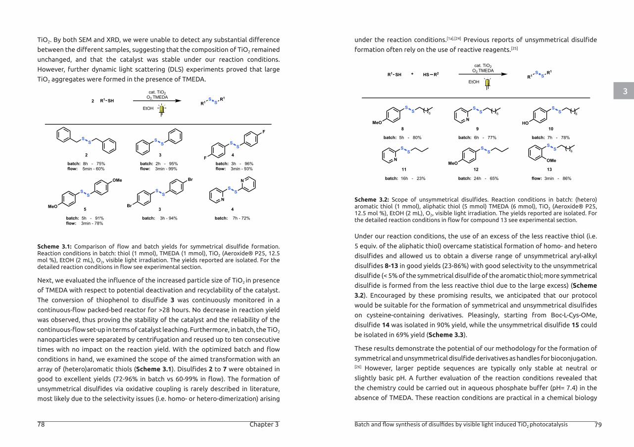
3
78 Chapter 3 Batch and flow synthesis of disulfides by visible light induced TiO2 photocatalysis 79
TiO2. By both SEM and XRD, we were unable to detect any substantial difference
between the different samples, suggesting that the composition of TiO2 remained
unchanged, and that the catalyst was stable under our reaction conditions.
However, further dynamic light scattering (DLS) experiments proved that large
TiO2 aggregates were formed in the presence of TMEDA.
Scheme 3.1: Comparison of flow and batch yields for symmetrical disulfide formation. Reaction conditions in batch: thiol (1 mmol), TMEDA (1 mmol), TiO2 (Aeroxide® P25, 12.5 mol %), EtOH (2 mL), O2, visible light irradiation. The yields reported are isolated. For the detailed reaction conditions in flow see experimental section.
Next, we evaluated the influence of the increased particle size of TiO2 in presence
of TMEDA with respect to potential deactivation and recyclability of the catalyst.
The conversion of thiophenol to disulfide 3 was continuously monitored in a
continuous-flow packed-bed reactor for >28 hours. No decrease in reaction yield
was observed, thus proving the stability of the catalyst and the reliability of the
continuous-flow set-up in terms of catalyst leaching. Furthermore, in batch, the TiO2
nanoparticles were separated by centrifugation and reused up to ten consecutive
times with no impact on the reaction yield. With the optimized batch and flow
conditions in hand, we examined the scope of the aimed transformation with an
array of (hetero)aromatic thiols (Scheme 3.1). Disulfides 2 to 7 were obtained in
good to excellent yields (72-96% in batch vs 60-99% in flow). The formation of
unsymmetrical disulfides via oxidative coupling is rarely described in literature,
most likely due to the selectivity issues (i.e. homo- or hetero-dimerization) arising
under the reaction conditions.[1a],[24] Previous reports of unsymmetrical disulfide
formation often rely on the use of reactive reagents.[25]
Scheme 3.2: Scope of unsymmetrical disulfides. Reaction conditions in batch: (hetero)aromatic thiol (1 mmol), aliphatic thiol (5 mmol) TMEDA (6 mmol), TiO2 (Aeroxide® P25, 12.5 mol %), EtOH (2 mL), O2, visible light irradiation. The yields reported are isolated. For the detailed reaction conditions in flow for compound 13 see experimental section.
Under our reaction conditions, the use of an excess of the less reactive thiol (i.e.
5 equiv. of the aliphatic thiol) overcame statistical formation of homo- and hetero
disulfides and allowed us to obtain a diverse range of unsymmetrical aryl-alkyl
disulfides 8-13 in good yields (23-86%) with good selectivity to the unsymmetrical
disulfide (< 5% of the symmetrical disulfide of the aromatic thiol; more symmetrical
disulfide is formed from the less reactive thiol due to the large excess) (Scheme
3.2). Encouraged by these promising results, we anticipated that our protocol
would be suitable for the formation of symmetrical and unsymmetrical disulfides
on cysteine-containing derivatives. Pleasingly, starting from Boc-L-Cys-OMe,
disulfide 14 was isolated in 90% yield, while the unsymmetrical disulfide 15 could
be isolated in 69% yield (Scheme 3.3).
These results demonstrate the potential of our methodology for the formation of
symmetrical and unsymmetrical disulfide derivatives as handles for bioconjugation.[26] However, larger peptide sequences are typically only stable at neutral or
slightly basic pH. A further evaluation of the reaction conditions revealed that
the chemistry could be carried out in aqueous phosphate buffer (pH= 7.4) in the
absence of TMEDA. These reaction conditions are practical in a chemical biology
2
cat. TiO2O2,TMEDA
EtOH
R1 SH2
SS S
S
F
F
SS
Br
Br
SS
MeO
OMe
S
NS
N
SS
batch: 8h - 75%flow: 5min - 60%
R1S
SR1
3
batch: 2h - 95%flow: 3min - 99%
4
batch: 3h - 96%flow: 3min - 93%
batch: 5h - 91%flow: 3min - 78%
batch: 3h - 94% batch: 7h - 72%
5 3 4
8
cat. TiO2O2,TMEDA
EtOHR1 SH
batch: 5h - 80%
R1S
SR1
9
batch: 6h - 77%
10
batch: 7h - 78%
batch: 16h - 23% batch: 24h - 65% flow: 3min - 86%
11 12 13
R2HS
SS
MeO
SS
MeO
S
NS
S
NS
SS
HO
6 6 6
SS 6
OMe
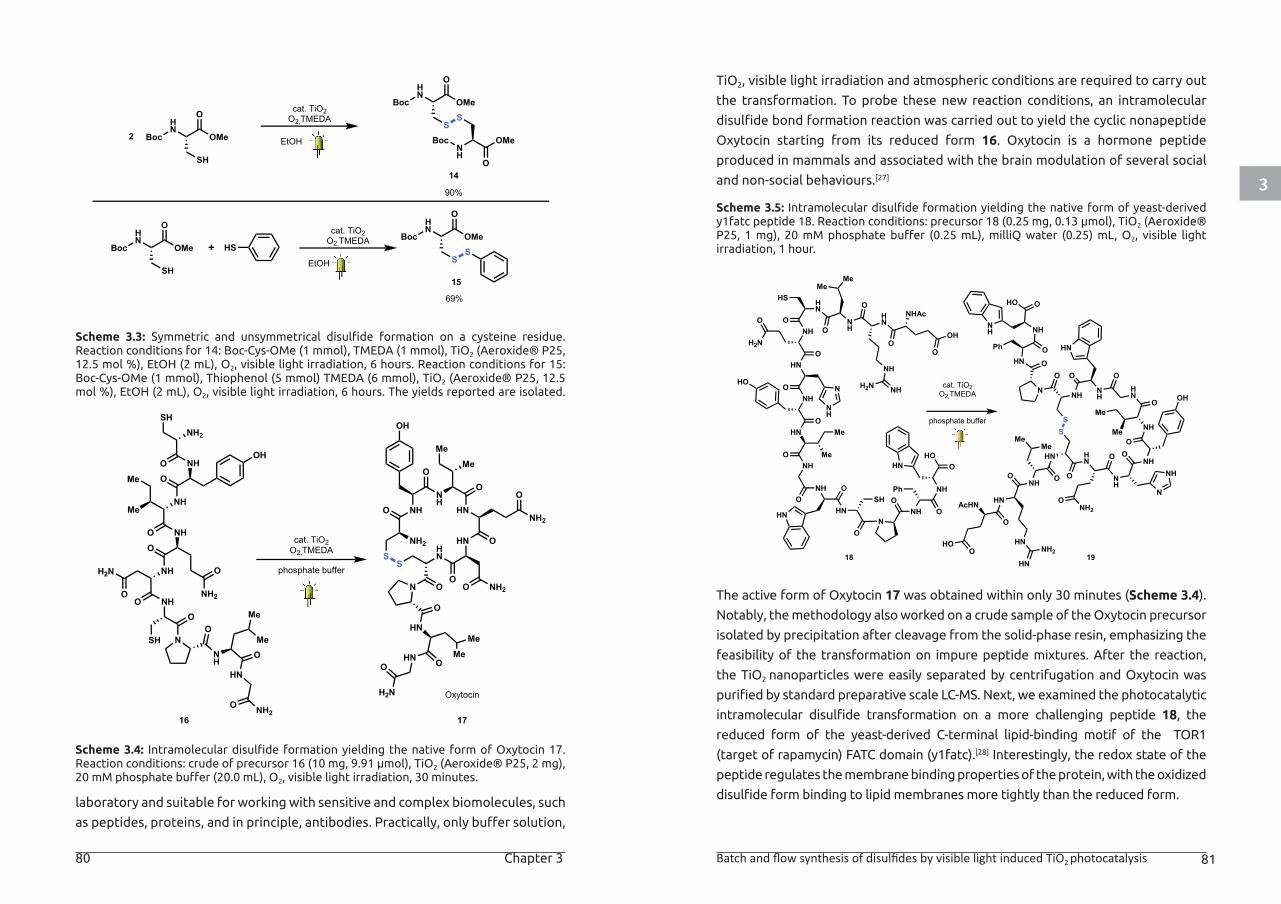
3
80 Chapter 3 Batch and flow synthesis of disulfides by visible light induced TiO2 photocatalysis 81
Scheme 3.3: Symmetric and unsymmetrical disulfide formation on a cysteine residue. Reaction conditions for 14: Boc-Cys-OMe (1 mmol), TMEDA (1 mmol), TiO2 (Aeroxide® P25, 12.5 mol %), EtOH (2 mL), O2, visible light irradiation, 6 hours. Reaction conditions for 15: Boc-Cys-OMe (1 mmol), Thiophenol (5 mmol) TMEDA (6 mmol), TiO2 (Aeroxide® P25, 12.5 mol %), EtOH (2 mL), O2, visible light irradiation, 6 hours. The yields reported are isolated.
Scheme 3.4: Intramolecular disulfide formation yielding the native form of Oxytocin 17. Reaction conditions: crude of precursor 16 (10 mg, 9.91 μmol), TiO2 (Aeroxide® P25, 2 mg), 20 mM phosphate buffer (20.0 mL), O2, visible light irradiation, 30 minutes.
laboratory and suitable for working with sensitive and complex biomolecules, such
as peptides, proteins, and in principle, antibodies. Practically, only buffer solution,
TiO2, visible light irradiation and atmospheric conditions are required to carry out
the transformation. To probe these new reaction conditions, an intramolecular
disulfide bond formation reaction was carried out to yield the cyclic nonapeptide
Oxytocin starting from its reduced form 16. Oxytocin is a hormone peptide
produced in mammals and associated with the brain modulation of several social
and non-social behaviours.[27]
Scheme 3.5: Intramolecular disulfide formation yielding the native form of yeast-derived y1fatc peptide 18. Reaction conditions: precursor 18 (0.25 mg, 0.13 μmol), TiO2 (Aeroxide® P25, 1 mg), 20 mM phosphate buffer (0.25 mL), milliQ water (0.25) mL, O2, visible light irradiation, 1 hour.
The active form of Oxytocin 17 was obtained within only 30 minutes (Scheme 3.4).
Notably, the methodology also worked on a crude sample of the Oxytocin precursor
isolated by precipitation after cleavage from the solid-phase resin, emphasizing the
feasibility of the transformation on impure peptide mixtures. After the reaction,
the TiO2 nanoparticles were easily separated by centrifugation and Oxytocin was
purified by standard preparative scale LC-MS. Next, we examined the photocatalytic
intramolecular disulfide transformation on a more challenging peptide 18, the
reduced form of the yeast-derived C-terminal lipid-binding motif of the TOR1
(target of rapamycin) FATC domain (y1fatc).[28] Interestingly, the redox state of the
peptide regulates the membrane binding properties of the protein, with the oxidized
disulfide form binding to lipid membranes more tightly than the reduced form.
cat. TiO2O2,TMEDA
EtOH
HS+
SH
HN
OMe
O
Boc SS
HN
OMe
O
Boc
SH
HN
OMe
O
Boc
SS
HN
OMe
O
Boc
NH
OMe
O14
15
2
90%
69%
Boc
cat. TiO2O2,TMEDA
EtOH
phosphate buffer
cat. TiO2O2,TMEDA
Me
NH
NH2
ONH
OO
MeNH
O
NHOH
O
NH2
SH
NH
N
H2N
OO
O
SHO
NH
Me
Me
HN
O
NH2O
Me
HNNH2
O
HN O
O
Me
NH
O
NH
OH
O
NH2
SHN
N NH2OO
O
S
O
HNMe
HN O
H2N
O
16 17
Me
Oxytocin
cat. TiO2O2,TMEDA
phosphate buffer
HN
HOO
O
AcHN
NHO
HN
HN
NH2
HN
O
MeMe
HN
O
S
NH
O
ONH2
NHO
NH
N
NH
O
OHHN
O
Me
Me
NH
O
NH
O
HN
O
S
N
HN O
NH
OPh
HO O
NH
HN
OH
OO
NHAcNH
O
NH
NHH2N
HN
O
MeMe
NHO
HS
HNO
O
H2N
NHO
NH
N
HNO
HO
NHO Me
Me
NHO
HN
O
HN
ON
NHO
NH
O
Ph
HOOHN
18
SH
19
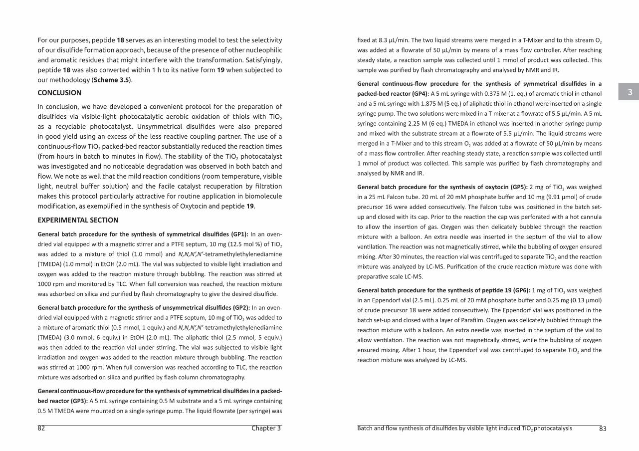
3
82 Chapter 3 Batch and flow synthesis of disulfides by visible light induced TiO2 photocatalysis 83
For our purposes, peptide 18 serves as an interesting model to test the selectivity
of our disulfide formation approach, because of the presence of other nucleophilic
and aromatic residues that might interfere with the transformation. Satisfyingly,
peptide 18 was also converted within 1 h to its native form 19 when subjected to
our methodology (Scheme 3.5).
CONCLUSION
In conclusion, we have developed a convenient protocol for the preparation of
disulfides via visible-light photocatalytic aerobic oxidation of thiols with TiO2
as a recyclable photocatalyst. Unsymmetrical disulfides were also prepared
in good yield using an excess of the less reactive coupling partner. The use of a
continuous-flow TiO2 packed-bed reactor substantially reduced the reaction times
(from hours in batch to minutes in flow). The stability of the TiO2 photocatalyst
was investigated and no noticeable degradation was observed in both batch and
flow. We note as well that the mild reaction conditions (room temperature, visible
light, neutral buffer solution) and the facile catalyst recuperation by filtration
makes this protocol particularly attractive for routine application in biomolecule
modification, as exemplified in the synthesis of Oxytocin and peptide 19.
EXPERIMENTAL SECTION
General batch procedure for the synthesis of symmetrical disulfides (GP1): In an oven-dried vial equipped with a magnetic stirrer and a PTFE septum, 10 mg (12.5 mol %) of TiO2 was added to a mixture of thiol (1.0 mmol) and N,N,N’,N’-tetramethylethylenediamine (TMEDA) (1.0 mmol) in EtOH (2.0 mL). The vial was subjected to visible light irradiation and oxygen was added to the reaction mixture through bubbling. The reaction was stirred at 1000 rpm and monitored by TLC. When full conversion was reached, the reaction mixture was adsorbed on silica and purified by flash chromatography to give the desired disulfide.
General batch procedure for the synthesis of unsymmetrical disulfides (GP2): In an oven-dried vial equipped with a magnetic stirrer and a PTFE septum, 10 mg of TiO2 was added to a mixture of aromatic thiol (0.5 mmol, 1 equiv.) and N,N,N’,N’-tetramethylethylenediamine (TMEDA) (3.0 mmol, 6 equiv.) in EtOH (2.0 mL). The aliphatic thiol (2.5 mmol, 5 equiv.) was then added to the reaction vial under stirring. The vial was subjected to visible light irradiation and oxygen was added to the reaction mixture through bubbling. The reaction was stirred at 1000 rpm. When full conversion was reached according to TLC, the reaction mixture was adsorbed on silica and purified by flash column chromatography.
General continuous-flow procedure for the synthesis of symmetrical disulfides in a packed-bed reactor (GP3): A 5 mL syringe containing 0.5 M substrate and a 5 mL syringe containing 0.5 M TMEDA were mounted on a single syringe pump. The liquid flowrate (per syringe) was
fixed at 8.3 μL/min. The two liquid streams were merged in a T-Mixer and to this stream O2 was added at a flowrate of 50 μL/min by means of a mass flow controller. After reaching steady state, a reaction sample was collected until 1 mmol of product was collected. This sample was purified by flash chromatography and analysed by NMR and IR.
General continuous-flow procedure for the synthesis of symmetrical disulfides in a packed-bed reactor (GP4): A 5 mL syringe with 0.375 M (1. eq.) of aromatic thiol in ethanol and a 5 mL syringe with 1.875 M (5 eq.) of aliphatic thiol in ethanol were inserted on a single syringe pump. The two solutions were mixed in a T-mixer at a flowrate of 5.5 μL/min. A 5 mL syringe containing 2.25 M (6 eq.) TMEDA in ethanol was inserted in another syringe pump and mixed with the substrate stream at a flowrate of 5.5 μL/min. The liquid streams were merged in a T-Mixer and to this stream O2 was added at a flowrate of 50 μL/min by means of a mass flow controller. After reaching steady state, a reaction sample was collected until 1 mmol of product was collected. This sample was purified by flash chromatography and analysed by NMR and IR.
General batch procedure for the synthesis of oxytocin (GP5): 2 mg of TiO2 was weighed in a 25 mL Falcon tube. 20 mL of 20 mM phosphate buffer and 10 mg (9.91 μmol) of crude precursor 16 were added consecutively. The Falcon tube was positioned in the batch set-up and closed with its cap. Prior to the reaction the cap was perforated with a hot cannula to allow the insertion of gas. Oxygen was then delicately bubbled through the reaction mixture with a balloon. An extra needle was inserted in the septum of the vial to allow ventilation. The reaction was not magnetically stirred, while the bubbling of oxygen ensured mixing. After 30 minutes, the reaction vial was centrifuged to separate TiO2 and the reaction mixture was analyzed by LC-MS. Purification of the crude reaction mixture was done with preparative scale LC-MS.
General batch procedure for the synthesis of peptide 19 (GP6): 1 mg of TiO2 was weighed in an Eppendorf vial (2.5 mL). 0.25 mL of 20 mM phosphate buffer and 0.25 mg (0.13 μmol) of crude precursor 18 were added consecutively. The Eppendorf vial was positioned in the batch set-up and closed with a layer of Parafilm. Oxygen was delicately bubbled through the reaction mixture with a balloon. An extra needle was inserted in the septum of the vial to allow ventilation. The reaction was not magnetically stirred, while the bubbling of oxygen ensured mixing. After 1 hour, the Eppendorf vial was centrifuged to separate TiO2 and the reaction mixture was analyzed by LC-MS.
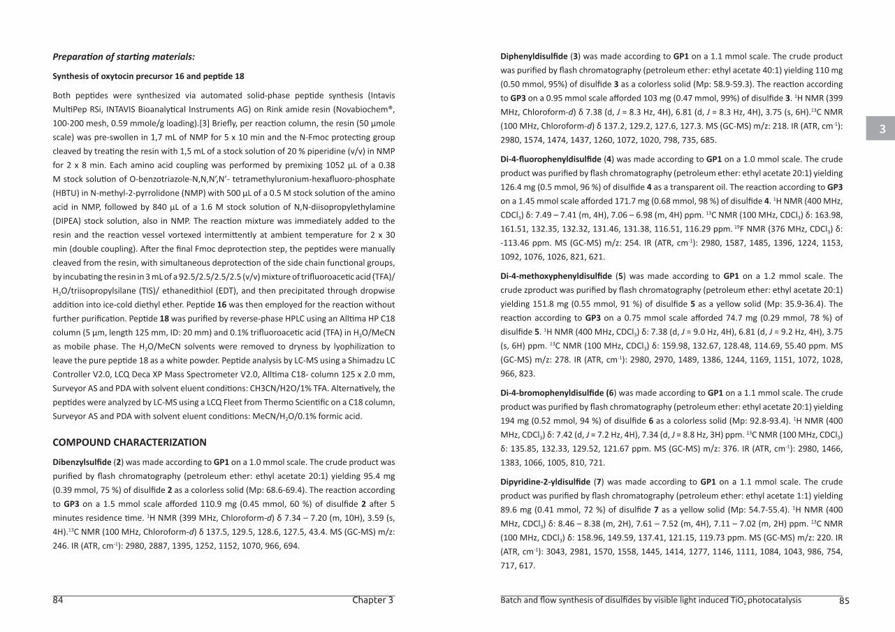
3
84 Chapter 3 Batch and flow synthesis of disulfides by visible light induced TiO2 photocatalysis 85
Preparation of starting materials:
Synthesis of oxytocin precursor 16 and peptide 18
Both peptides were synthesized via automated solid-phase peptide synthesis (Intavis MultiPep RSi, INTAVIS Bioanalytical Instruments AG) on Rink amide resin (Novabiochem®, 100-200 mesh, 0.59 mmole/g loading).[3] Briefly, per reaction column, the resin (50 µmole scale) was pre-swollen in 1,7 mL of NMP for 5 x 10 min and the N-Fmoc protecting group cleaved by treating the resin with 1,5 mL of a stock solution of 20 % piperidine (v/v) in NMP for 2 x 8 min. Each amino acid coupling was performed by premixing 1052 µL of a 0.38 M stock solution of O-benzotriazole-N,N,N’,N’- tetramethyluronium-hexafluoro-phosphate (HBTU) in N-methyl-2-pyrrolidone (NMP) with 500 µL of a 0.5 M stock solution of the amino acid in NMP, followed by 840 µL of a 1.6 M stock solution of N,N-diisopropylethylamine (DIPEA) stock solution, also in NMP. The reaction mixture was immediately added to the resin and the reaction vessel vortexed intermittently at ambient temperature for 2 x 30 min (double coupling). After the final Fmoc deprotection step, the peptides were manually cleaved from the resin, with simultaneous deprotection of the side chain functional groups, by incubating the resin in 3 mL of a 92.5/2.5/2.5/2.5 (v/v) mixture of trifluoroacetic acid (TFA)/H2O/triisopropylsilane (TIS)/ ethanedithiol (EDT), and then precipitated through dropwise addition into ice-cold diethyl ether. Peptide 16 was then employed for the reaction without further purification. Peptide 18 was purified by reverse-phase HPLC using an Alltima HP C18 column (5 μm, length 125 mm, ID: 20 mm) and 0.1% trifluoroacetic acid (TFA) in H2O/MeCN as mobile phase. The H2O/MeCN solvents were removed to dryness by lyophilization to leave the pure peptide 18 as a white powder. Peptide analysis by LC-MS using a Shimadzu LC Controller V2.0, LCQ Deca XP Mass Spectrometer V2.0, Alltima C18- column 125 x 2.0 mm, Surveyor AS and PDA with solvent eluent conditions: CH3CN/H2O/1% TFA. Alternatively, the peptides were analyzed by LC-MS using a LCQ Fleet from Thermo Scientific on a C18 column, Surveyor AS and PDA with solvent eluent conditions: MeCN/H2O/0.1% formic acid.
COMPOUND CHARACTERIZATION
Dibenzylsulfide (2) was made according to GP1 on a 1.0 mmol scale. The crude product was purified by flash chromatography (petroleum ether: ethyl acetate 20:1) yielding 95.4 mg (0.39 mmol, 75 %) of disulfide 2 as a colorless solid (Mp: 68.6-69.4). The reaction according to GP3 on a 1.5 mmol scale afforded 110.9 mg (0.45 mmol, 60 %) of disulfide 2 after 5 minutes residence time. 1H NMR (399 MHz, Chloroform-d) δ 7.34 – 7.20 (m, 10H), 3.59 (s, 4H).13C NMR (100 MHz, Chloroform-d) δ 137.5, 129.5, 128.6, 127.5, 43.4. MS (GC-MS) m/z: 246. IR (ATR, cm-1): 2980, 2887, 1395, 1252, 1152, 1070, 966, 694.
Diphenyldisulfide (3) was made according to GP1 on a 1.1 mmol scale. The crude product was purified by flash chromatography (petroleum ether: ethyl acetate 40:1) yielding 110 mg (0.50 mmol, 95%) of disulfide 3 as a colorless solid (Mp: 58.9-59.3). The reaction according to GP3 on a 0.95 mmol scale afforded 103 mg (0.47 mmol, 99%) of disulfide 3. 1H NMR (399 MHz, Chloroform-d) δ 7.38 (d, J = 8.3 Hz, 4H), 6.81 (d, J = 8.3 Hz, 4H), 3.75 (s, 6H).13C NMR (100 MHz, Chloroform-d) δ 137.2, 129.2, 127.6, 127.3. MS (GC-MS) m/z: 218. IR (ATR, cm-1): 2980, 1574, 1474, 1437, 1260, 1072, 1020, 798, 735, 685.
Di-4-fluorophenyldisulfide (4) was made according to GP1 on a 1.0 mmol scale. The crude product was purified by flash chromatography (petroleum ether: ethyl acetate 20:1) yielding 126.4 mg (0.5 mmol, 96 %) of disulfide 4 as a transparent oil. The reaction according to GP3 on a 1.45 mmol scale afforded 171.7 mg (0.68 mmol, 98 %) of disulfide 4. 1H NMR (400 MHz, CDCl3) δ: 7.49 – 7.41 (m, 4H), 7.06 – 6.98 (m, 4H) ppm. 13C NMR (100 MHz, CDCl3) δ: 163.98, 161.51, 132.35, 132.32, 131.46, 131.38, 116.51, 116.29 ppm. 19F NMR (376 MHz, CDCl3) δ: -113.46 ppm. MS (GC-MS) m/z: 254. IR (ATR, cm-1): 2980, 1587, 1485, 1396, 1224, 1153, 1092, 1076, 1026, 821, 621.
Di-4-methoxyphenyldisulfide (5) was made according to GP1 on a 1.2 mmol scale. The crude zproduct was purified by flash chromatography (petroleum ether: ethyl acetate 20:1) yielding 151.8 mg (0.55 mmol, 91 %) of disulfide 5 as a yellow solid (Mp: 35.9-36.4). The reaction according to GP3 on a 0.75 mmol scale afforded 74.7 mg (0.29 mmol, 78 %) of disulfide 5. 1H NMR (400 MHz, CDCl3) δ: 7.38 (d, J = 9.0 Hz, 4H), 6.81 (d, J = 9.2 Hz, 4H), 3.75 (s, 6H) ppm. 13C NMR (100 MHz, CDCl3) δ: 159.98, 132.67, 128.48, 114.69, 55.40 ppm. MS (GC-MS) m/z: 278. IR (ATR, cm-1): 2980, 2970, 1489, 1386, 1244, 1169, 1151, 1072, 1028, 966, 823.
Di-4-bromophenyldisulfide (6) was made according to GP1 on a 1.1 mmol scale. The crude product was purified by flash chromatography (petroleum ether: ethyl acetate 20:1) yielding 194 mg (0.52 mmol, 94 %) of disulfide 6 as a colorless solid (Mp: 92.8-93.4). 1H NMR (400 MHz, CDCl3) δ: 7.42 (d, J = 7.2 Hz, 4H), 7.34 (d, J = 8.8 Hz, 3H) ppm. 13C NMR (100 MHz, CDCl3) δ: 135.85, 132.33, 129.52, 121.67 ppm. MS (GC-MS) m/z: 376. IR (ATR, cm-1): 2980, 1466, 1383, 1066, 1005, 810, 721.
Dipyridine-2-yldisulfide (7) was made according to GP1 on a 1.1 mmol scale. The crude product was purified by flash chromatography (petroleum ether: ethyl acetate 1:1) yielding 89.6 mg (0.41 mmol, 72 %) of disulfide 7 as a yellow solid (Mp: 54.7-55.4). 1H NMR (400 MHz, CDCl3) δ: 8.46 – 8.38 (m, 2H), 7.61 – 7.52 (m, 4H), 7.11 – 7.02 (m, 2H) ppm. 13C NMR (100 MHz, CDCl3) δ: 158.96, 149.59, 137.41, 121.15, 119.73 ppm. MS (GC-MS) m/z: 220. IR (ATR, cm-1): 3043, 2981, 1570, 1558, 1445, 1414, 1277, 1146, 1111, 1084, 1043, 986, 754, 717, 617.
3
86 Chapter 3 Batch and flow synthesis of disulfides by visible light induced TiO2 photocatalysis 87
S-(4-methoxyphenyl)-S’-(octyl)-disulfide (8) was made according to GP2 on a 0.53 mmol scale. The crude product was purified by flash chromatography (petroleum ether: ethyl acetate 40:1) yielding 120 mg (0.42 mmol, 80 %) of disulfide 8 as an oil. 1H NMR (400 MHz, CDCl3) δ: 7.49 (d, J = 9.1 Hz, 2H), 6.87 (d, J = 7.3 Hz, 2H), 3.81 (s, 3H), 2.74 (t, J = 7.3 Hz, 2H), 1.72 – 1.62 (m, 2H), 1.39 – 1.23 (m, 10H), 0.93 – 0.85 (m, 3H) ppm. 13C NMR (100 MHz, CDCl3) δ: 159.58, 131.70, 128.70, 114.70, 55.45, 39.04, 31.91, 29.25, 28.83, 28.59, 22.75, 14.20 ppm. MS (GC-MS) m/z: 284. IR (ATR, cm-1): 2926, 1713, 1491, 1362, 1246, 1221, 910, 825, 731.
S-(pyridine)-S’-(octyl)-disulfide (9) was made according to GP2 on a 0.49 mmol scale. The crude product was purified by flash chromatography (petroleum ether: ethyl acetate 9:1 to 1:1) yielding 95.9 mg (0.38 mmol, 77 %) of disulfide 9 as an oil. 1H NMR (399 MHz, Chloroform-d) δ = 8.43 (s, 1H), 7.71 (d, J=7.4, 1H), 7.61 (t, J=7.7, 1H), 7.05 (s, 1H), 2.85 – 2.61 (m, 2H), 1.75 – 1.60 (m, 2H), 1.45 – 1.15 (m, 10H), 0.85 (s, 3H). 13C NMR (100 MHz, CDCl3) δ: 160.80, 149.61, 136.98, 120.49, 119.56, 39.10, 29.31, 29.28, 29.26, 29.21, 22.70, 14.17 ppm. MS (GC-MS) m/z: 255. IR (ATR, cm-1): 2924, 2853, 1574, 1558, 1445, 1418, 1117, 758, 717.
S-(phenol)-S’-(octyl)-disulfide (10) was made according to GP2 on a 0.72 mmol scale. The crude product was purified by flash chromatography (petroleum ether: ethyl acetate 20:1 to 9:1) yielding 151.9 mg (0.56 mmol, 77 %) of disulfide 10 as an oil. 1H NMR (400 MHz, CDCl3) δ: 7.43 (d, J = 8.1 Hz, 2H), 6.80 (d, J = 8.1 Hz, 2H), 2.73 (t, J = 7.3 Hz, 2H), 1.71 – 1.62 (m, 2H), 1.38 – 1.19 (m, 10H), 0.88 (t, J = 6.8 Hz, 3H) ppm. 13C NMR (100 MHz, CDCl3) δ: 155.53, 131.90, 128.88, 116.23, 39.04, 31.89, 29.24, 28.83, 28.59, 22.75, 14.20 ppm. MS (GC-MS) m/z: 270. IR (ATR, cm-1): 2924, 1489, 1456, 1234, 1167, 824.
S-(pyridine)-S’-(propyl)-disulfide (11) was made according to GP2 on a 0.81 mmol scale. The crude product was purified by flash chromatography (petroleum ether: ethyl acetate 9:1) yielding 34.7 mg (0.19 mmol, 23 %) of disulfide 11 as an oil. 1H NMR (400 MHz, CDCl3) δ: 8.44 (d, J = 4.9 Hz, 1H), 7.72 (d, J = 8.1 Hz, 1H), 7.63 (t, J = 7.8 Hz, 1H), 7.06 (t, J = 6.1 Hz, 1H), 2.81 – 2.61 (m, 2H), 1.78 – 1.65 (m, 2H), 0.98 (t, J = 7.4 Hz, 3H) ppm. 13C NMR (100 MHz, CDCl3) δ: 160.81, 149.65, 137.04, 120.55, 119.59, 41.03, 22.41, 13.22 ppm. MS (GC-MS) m/z: 185. IR (ATR, cm-1): 1711, 1418, 1362, 1221, 910, 729.
S-(4-methoxyphenyl)-S’-(propyl)-disulfide (12) was made according to GP2 on a 0.50 mmol scale. The crude product was purified by flash chromatography (petroleum ether: ethyl acetate 40:1) yielding 70.5 mg (0.32 mmol, 65 %) of disulfide 12 as an oil. 1H NMR (400 MHz, CDCl3) δ: 7.48 (d, J = 8.7 Hz, 2H), 6.87 (d, J = 8.9 Hz, 2H), 3.81 (s, 3H), 2.71 (t, J = 7.2 Hz, 2H), 1.78 – 1.65 (m, 2H), 0.97 (t, J = 7.4 Hz, 3H) ppm. 13C NMR (100 MHz, CDCl3) δ: 159.59, 131.68,
128.67, 114.73, 55.49, 40.97, 22.21, 13.22 ppm. MS (GC-MS) m/z: 214. IR (ATR, cm-1): 2960, 1591, 1458, 1287, 1244, 1171, 1032, 824.
S-(2-methoxyphenyl)-S’-(octyl)-disulfide (13) was made according to GP4
on a 0.52 mmol scale. The crude product was purified by flash chromatography
(petroleum ether: ethyl acetate 40:1) yielding 122.1 mg (0.45 mmol, 86 %) of disulfide 13 as an oil. 1H NMR (400 MHz, CDCl3) δ: 7.72 (d, J = 6.0 Hz, 1H), 7.30 – 7.17 (m, 1H), 7.01 (t, J = 7.7 Hz, 1H), 6.86 (d, J = 8.2 Hz, 1H), 3.89 (s, 3H), 2.73 (t, J = 7.4 Hz, 2H), 1.74 – 1.64 (m, 2H), 1.43 – 1.21 (m, 10H), 0.90 (t, 3H) ppm. 13C NMR (100 MHz, CDCl3) δ: 156.60, 127.70, 127.66, 125.61, 121.26, 121.15, 110.69, 55.92, 38.79, 31.89, 29.25, 29.03, 28.65, 22.74, 14.20 ppm. MS (GC-MS) m/z: 284. IR (ATR, cm-1): 2924, 1578, 1474, 1462, 1433, 1269, 1236, 1057, 1024, 744, 677.
N-Boc-cysteine-OMe disulfide (14) was made according to GP1 on a 1 mmol scale. The crude product was purified by flash chromatography (petroleum ether: ethyl acetate 3:1) yielding 212.8 mg (0.46 mmol, 90 %) of disulfide 14 as an oil. 1H NMR (400 MHz, Chloroform-d) δ = 5.38 (d, J=6.8, 2H), 4.59 (d, J=6.5, 2H), 3.75 (s, 6H), 3.15 (d, J=4.7, 4H), 1.44 (s, 18H) ppm. 13C NMR (101 MHz, Chloroform-d) δ = 171.2, 155.1, 80.3, 52.8, 52.6, 41.3, 28.3 ppm. MS (LC-MS) [M-2*Boc]+1: 269.17.
Methyl N-(tert-butoxycarbonyl)-S-(phenylthio)-L-cysteinate (15) was made according to GP2 on a 1 mmol scale. The crude product was purified by flash chromatography (petroleum ether: ethyl acetate 10:1) yielding 236.9 mg (0.69 mmol, 69 %) of disulfide 15 as yellow oil. 1H NMR (400 MHz, Chloroform-d) δ = 7.59 – 7.49 (m, 2H), 7.40 – 7.31 (m, 2H), 7.30 – 7.25 (m, 1H), 5.31 (s, 1H), 4.63 (s, 1H), 3.74 (s, 3H), 3.38 – 3.04 (m, 2H), 1.44 (s, 9H) ppm. 13C NMR (101 MHz, Chloroform-d) δ = 171.1, 155.0, 136.6, 129.2, 128.3, 127.4, 80.2, 52.9, 52.6, 40.9, 28.3 ppm.MS (LC-MS) [M-*Boc]+1: 244.08.
ASSOCIATED CONTENT
The Supporting Information for this article is available free of charge on the Wiley Publications website at DOI: 10.1002/cssc.201600602.
3
88 Chapter 3 Batch and flow synthesis of disulfides by visible light induced TiO2 photocatalysis 89
REFERENCES:[1] a) B. Mandal, B. Basu, RSC Adv. 2014, 4, 13854-13881; b) D. Witt, Synthesis 2008, 16,
2491-2509.
[2] M. Góngora-Benítez, J. Tulla-Puche, F. Albericio, Chem. Rev. 2014, 114, 901-926.
[3] M. N. Alam, S. K. Mandal, K. Roy, S. C. Debnath, Int. J. Ind. Chem. 2014, 5, 1-11.
[4] a) A. Dhakshinamoorthy, S. Navalon, D. Sempere, M. Alvaro, H. Garcia, ChemCatChem 2013, 5, 241-246; b) A. Corma, T. Rodenas, M. J. Sabater, Chem. Sci. 2012, 3, 398-404; c) P. Kumar, G. Singh, D. Tripathi, S. L. Jain, RSC Adv. 2014, 4, 50331-50337; d) X.-B. Li, Z.-J. Li, Y.-J. Gao, Q.-Y. Meng, S. Yu, R. G. Weiss, C.-H. Tung, L.-Z. Wu, Angew. Chem., Int. Ed. 2014, 53, 2085-2089; e) M. Oba, K. Tanaka, K. Nishiyama, W. Ando, J. Org. Chem. 2011, 76, 4173-4177; f) K. Y. D. Tan, G. F. Teng, W. Y. Fan, Organometallics 2011, 30, 4136-4143; g) A. Dhakshinamoorthy, M. Alvaro, H. Garcia, Chem. Commun. (Cambridge, U. K.) 2010, 46, 6476-6478.
[5] a) S. B. Gunnoo, A. Madder, ChemBioChem 2016, 17, 529-553; b) T. M. Postma, F. Albericio, Eur. J. Org. Chem. 2014, 17, 3519-3530; c) G. Bulaj, Biotechnol. Adv. 2005, 23, 87-92.
[6] a) C. D. Spicer, B. G. Davis, Nat. Commun. 2014, 5, 4740; b) F. López-Gallego, O. Abian, J. M. Guisán, Biochemistry 2012, 51, 7028-7036; c) T. List, G. Casi, D. Neri, Mol. Cancer Ther. 2014, 13, 2641-2652; d) J. M. Chalker, G. J. L. Bernardes, B. G. Davis, Acc. Chem. Res. 2011, 44, 730-741; e) J. M. Chalker, S. B. Gunnoo, O. Boutureira, S. C. Gerstberger, M. Fernández-González, G. J. L. Bernardes, L. Griffin, H. Hailu, C. J. Schofield, B. G. Davis, Chem. Sci. 2011, 2, 1666-1676; f) J. P. Tam, C. R. Wu, W. Liu, J. W. Zhang, J. Am. Chem. Soc. 1991, 113, 6657-6662.
[7] a) S. Ganta, H. Devalapally, A. Shahiwala, M. Amiji, J. Controlled Release 2008, 126, 187-204; b) A. M. Sauer, A. Schlossbauer, N. Ruthardt, V. Cauda, T. Bein, C. Bräuchle, Nano Lett. 2010, 10, 3684-3691; c) G. J. L. Bernardes, G. Casi, S. Trüssel, I. Hartmann, K. Schwager, J. Scheuermann, D. Neri, Angew. Chem., Int. Ed. 2012, 124, 965-968; d) P. Akkapeddi, S.-A. Azizi, A. M. Freedy, P. M. S. D. Cal, P. M. P. Gois, G. J. L. Bernardes, Chem. Sci. 2016, 7, 2954-2963.
[8] G. L. Ellman, Arch. Biochem. Biophys. 1959, 82, 70-77.
[9] A. Talla, B. Driessen, N. J. W. Straathof, L.-G. Milroy, L. Brunsveld, V. Hessel, T. Noël, Adv. Synth. Catal. 2015, 357, 2180-2186.
[10] O. Boutureira, G. J. L. Bernardes, Chem. Rev. 2015, 115, 2174-2195.
[11] V. T. Bhat, P. A. Duspara, S. Seo, N. S. B. Abu Bakar, M. F. Greaney, Chem. Commun. (Cambridge, U. K.) 2015, 51, 4383-4385.
[12] a) S. Malato, P. Fernández-Ibáñez, M. I. Maldonado, J. Blanco, W. Gernjak, Catal. Today 2009, 147, 1-59; b) J. Blanco, S. Malato, P. Fernández-Ibañez, D. Alarcón, W. Gernjak, M. I. Maldonado, Renewable Sustainable Energy Rev. 2009, 13, 1437-1445; c) P. Fernández-Ibáñez, J. Blanco, S. Malato, F. J. d. l. Nieves, Water Res. 2003, 37, 3180-3188; d) J. n. Blanco-Galvez, P. Fernández-Ibáñez, S. Malato-Rodríguez, J. Sol. Energy Eng. 2007, 129, 4-15.
[13] a) M. Baghbanzadeh, T. N. Glasnov, C. O. Kappe, J. Flow Chem. 2013, 3, 109-113; b) G. Takei, T. Kitamori, H. Kim, Catal. Commun. 2005, 6, 357-360; c) F. Parrino, A. Ramakrishnan, H. Kisch, Angew. Chem., Int. Ed. 2008, 47, 7107-7109; d) M. Cherevatskaya, M. Neumann,
S. Füldner, C. Harlander, S. Kümmel, S. Dankesreiter, A. Pfitzner, K. Zeitler, B. König, Angew. Chem., Int. Ed. 2012, 51, 4062-4066; e) M. Rueping, J. Zoller, D. C. Fabry, K. Poscharny, R. M. Koenigs, T. E. Weirich, J. Mayer, Chem. - Eur. J. 2012, 18, 3478-3481; f) C. D. McTiernan, S. P. Pitre, H. Ismaili, J. C. Scaiano, Adv. Synth. Catal. 2014, 356, 2819-2824.
[14] U. I. Gaya, A. H. Abdullah, J. Photochem. Photobiol., C 2008, 9, 1-12.
[15] a) M. T. Neves-Petersen, G. P. Gajula, S. Petersen, InTech, Rijeka, 2012, DOI: 10.5772/37947; b) D. V. Bent, E. Hayon, J. Am. Chem. Soc. 1975, 97, 2599-2606; c) D. V. Bent, E. Hayon, J. Am. Chem. Soc. 1975, 97, 2606-2612; d) D. V. Bent, E. Hayon, J. Am. Chem. Soc. 1975, 97, 2612-2619.
[16] a) X. Lang, X. Chen, J. Zhao, Chem. Soc. Rev. 2014, 43, 473-486; b) G. Zhang, G. Kim, W. Choi, Energy Environ. Sci. 2014, 7, 954-966; c) X. Lang, J. Zhao, X. Chen, Angew. Chem., Int. Ed. 2016, 55, 4697-4700; d) X. Lang, W. Ma, Y. Zhao, C. Chen, H. Ji, J. Zhao, Chem. - Eur. J. 2012, 18, 2624-2631; e) X. Lang, W. R. Leow, J. Zhao, X. Chen, Chem. Sci. 2015, 6, 1075-1082; f) C. Vila, M. Rueping, Green Chem. 2013, 15, 2056-2059; g) C. Chen, W. Ma, J. Zhao, Chem. Soc. Rev. 2010, 39, 4206-4219.
[17] X. Lang, W. Hao, W. R. Leow, S. Li, J. Zhao, X. Chen, Chem. Sci. 2015, 6, 5000-5005.
[18] H. J. Kim, J. H. Yoon, S. Yoon, J. Phys. Chem. A 2010, 114, 12010-12015.
[19] a) D. Cambié, C. Bottecchia, N. J. W. Straathof, V. Hessel, T. Noël, Chem. Rev. 2016, 116, 10276-10341; b) N. J. W. Straathof, Y. Su, V. Hessel, T. Noël, Nat. Protoc. 2015, 11, 10-21.
[20] a) H. P. L. Gemoets, Y. Su, M. Shang, V. Hessel, R. Luque, T. Noël, Chem. Soc. Rev. 2015, 45, 83-117; b) A. Gunther, K. F. Jensen, Lab Chip 2006, 6, 1487-1503; c) R. L. Hartman, J. P. McMullen, K. F. Jensen, Angew. Chem., Int. Ed. 2011, 50, 7502-7519.
[21] a) T. Noël, Y. Su, V. Hessel, in Top. Organomet. Chem., 2016, 57, 1-42; b) B. Pieber, C. O. Kappe, in Top. Organomet. Chem., 2016, 57, 97-136.
[22] a) Y. Su, N. J. W. Straathof, V. Hessel, T. Noël, Chem. - Eur. J. 2014, 20, 10562-10589; b) J. P. Knowles, L. D. Elliott, K. I. Booker-Milburn, Beilstein J. Org. Chem. 2012, 8, 2025-2052; c) R. Ciriminna, R. Delisi, Y.-J. Xu, M. Pagliaro, Org. Process Res. Dev. 2016, 20, 403-408.
[23] a) A. Veres, J. Menesi, C. Janaky, G. F. Samu, M. K. Scheyer, Q. Xu, F. Salahioglu, M. V. Garland, I. Dekany, Z. Zhong, RSC Adv. 2015, 5, 2421-2428; b) D. Reyes-Coronado, G. Rodríguez-Gattorno, M. E. Espinosa-Pesqueira, C. Cab, R. d. Coss, G. Oskam, Nanotechnology 2008, 19, 145605.
[24] A. K. Chatterjee, T.-L. Choi, D. P. Sanders, R. H. Grubbs, J. Am. Chem. Soc. 2003, 125, 11360-11370.
[25] a) E. Brzezinska, A. L. Ternay, J. Org. Chem. 1994, 59, 8239-8244; b) K. Tanaka, K. Ajiki, Tetrahedron Lett. 2004, 45, 5677-5679; c) M. Han, J. T. Lee, H.-G. Hahn, Tetrahedron Lett. 2011, 52, 236-239; d) J. Pan, M. Xian, Chem. Commun. (Cambridge, U. K.) 2011, 47, 352-354; e) J. K. Vandavasi, W.-P. Hu, C.-Y. Chen, J.-J. Wang, Tetrahedron 2011, 67, 8895-8901.
[26] a) N. Krall, F. P. da Cruz, O. Boutureira, G. J. L. Bernardes, Nat Chem 2016, 8, 103-113; b) G. J. L. Bernardes, E. J. Grayson, S. Thompson, J. M. Chalker, J. C. Errey, F. El Oualid, T. D. W. Claridge, B. G. Davis, Angew. Chem., Int. Ed. 2008, 47, 2244-2247.
90 Chapter 3
[27] a) C. S. Carter, Annu. Rev. Psychol. 2014, 65, 17-39; b) B.-H. Hu, P. Sun, W. Tang, Y. Huang, Synlett 2017, 28, 1780-1784.
[28] S. A. Dames, J. Biol. Chem. 2009, 285, 7766-7775.
CHAPTER 4
Visible Light-Mediated Selective Arylation of Cysteine in Batch and Flow
This chapter is based on:
Bottecchia, C.; Rubens, M.; Gunnoo, S. B.; Madder, A.; Noël, T. Angew. Chem, Int. Ed. 2017, 56, 12702-12707
4
94 Chapter 4 Visible-Light-Mediated Selective Arylation of Cysteine in Batch and Flow 95
ABSTRACT
In this chapter, a mild visible light-mediated strategy for cysteine arylation is
presented. The method relies on the use of Eosin Y as a metal-free photocatalyst
and aryldiazonium salts as arylating agents. The reaction can be significantly
accelerated in a microflow reactor, whilst allowing the in situ formation of the
required diazonium salts. The batch and flow protocol described herein can be
applied to obtain a broad series of arylated cysteine derivatives and arylated
cysteine-containing dipeptides. Moreover, the method was applied to the
chemoselective arylation of a model peptide in biocompatible reaction conditions
(room temperature, PBS buffer) within a short reaction time.
INTRODUCTION
The formation of C–S bonds is of high interest in the fields of organic synthesis
and drug discovery.[1] However, due to the undesired coordination between
metal catalysts and sulfur atoms, traditional cross-coupling methods are often
inadequate strategies for C–S bond formation.[2] Despite this, some transition-
metal catalyzed cross-coupling methods for C–S bond formation have been
reported.[3] However, these methods often rely on high reaction temperatures
and/or require stoichiometric amounts of a strong base. A well-known strategy
largely applied in industry for C–S bond formation is the so-called Stadler-Ziegler
reaction, in which a diazonium salt is reacted with an aryl thiolate to afford the
desired thioether derivative.[4] Starting from the original conditions reported by
Stadler and by Ziegler, a plethora of methodologies have emerged, allowing milder
reaction conditions.[5] Among them, our group reported a mild one-pot procedure
for the synthesis of aryl sulfides facilitated by photoredox catalysis.[6]
In the interest of developing mild methodologies for chemical biology purposes[7],
we envisaged modifying our procedure to achieve a visible light-induced protocol
for cysteine arylation. Specifically, we directed our attention towards the
development of a biocompatible metal-free strategy involving inexpensive organic
dyes as photoredox catalysts. In addition, due to the incompatibility of UV light to
peptides and proteins, we reasoned that visible-light photoredox catalysis would
be perfectly suited to chemical biology applications owing to the milder reaction
conditions (e.g. room temperature and visible light).
Novel selective chemical modifications of peptides and proteins are of pivotal
importance for the study of protein-protein interactions and for the development
of novel bioconjugates and drug candidates.[8] Compared to other amino acids
commonly targeted for post-translational modifications, cysteine exhibits
low natural abundancy and a relatively high nucleophilicity.[9] Together, these
characteristics account for the generally higher selectivity and the broad reactivity
profile typical for post-translational chemical modifications involving cysteine
residues. Some of the most widespread strategies for cysteine bioconjugation
include disulfide formation,[10] thiol-maleimide reactions,[11] and alkylation with
haloalkyl reagents.[12] Other strategies use cysteine as precursor for the formation
of dehydroalanine[13] (Dha), or as a handle for nucleophilic aromatic substitution
allowing access to perfluorinated staples in peptides and proteins.[14] Moreover,
several methodologies relying on thiol-ene[11] (or thiol-yne[15]) reactions have
been reported, often requiring UV irradiation to generate the thiyl radical.
Fewer records in the literature describe the use of transition metals for cysteine
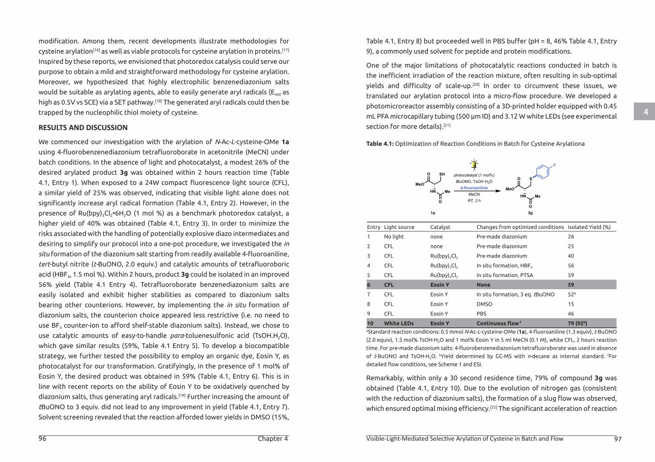
4
96 Chapter 4 Visible-Light-Mediated Selective Arylation of Cysteine in Batch and Flow 97
modification. Among them, recent developments illustrate methodologies for
cysteine arylation[16] as well as viable protocols for cysteine arylation in proteins.[17]
Inspired by these reports, we envisioned that photoredox catalysis could serve our
purpose to obtain a mild and straightforward methodology for cysteine arylation.
Moreover, we hypothesized that highly electrophilic benzenediazonium salts
would be suitable as arylating agents, able to easily generate aryl radicals (Ered as
high as 0.5V vs SCE) via a SET pathway.[18] The generated aryl radicals could then be
trapped by the nucleophilic thiol moiety of cysteine.
RESULTS AND DISCUSSION
We commenced our investigation with the arylation of N-Ac-L-cysteine-OMe 1a
using 4-fluorobenzenediazonium tetrafluoroborate in acetonitrile (MeCN) under
batch conditions. In the absence of light and photocatalyst, a modest 26% of the
desired arylated product 3g was obtained within 2 hours reaction time (Table
4.1, Entry 1). When exposed to a 24W compact fluorescence light source (CFL),
a similar yield of 25% was observed, indicating that visible light alone does not
significantly increase aryl radical formation (Table 4.1, Entry 2). However, in the
presence of Ru(bpy)3Cl2•6H2O (1 mol %) as a benchmark photoredox catalyst, a
higher yield of 40% was obtained (Table 4.1, Entry 3). In order to minimize the
risks associated with the handling of potentially explosive diazo intermediates and
desiring to simplify our protocol into a one-pot procedure, we investigated the in
situ formation of the diazonium salt starting from readily available 4-fluoroaniline,
tert-butyl nitrite (t-BuONO, 2.0 equiv.) and catalytic amounts of tetrafluoroboric
acid (HBF4, 1.5 mol %). Within 2 hours, product 3g could be isolated in an improved
56% yield (Table 4.1 Entry 4). Tetrafluoroborate benzenediazonium salts are
easily isolated and exhibit higher stabilities as compared to diazonium salts
bearing other counterions. However, by implementing the in situ formation of
diazonium salts, the counterion choice appeared less restrictive (i.e. no need to
use BF4 counter-ion to afford shelf-stable diazonium salts). Instead, we chose to
use catalytic amounts of easy-to-handle para-toluenesulfonic acid (TsOH.H2O),
which gave similar results (59%, Table 4.1 Entry 5). To develop a biocompatible
strategy, we further tested the possibility to employ an organic dye, Eosin Y, as
photocatalyst for our transformation. Gratifyingly, in the presence of 1 mol% of
Eosin Y, the desired product was obtained in 59% (Table 4.1, Entry 6). This is in
line with recent reports on the ability of Eosin Y to be oxidatively quenched by
diazonium salts, thus generating aryl radicals.[19] Further increasing the amount of
tBuONO to 3 equiv. did not lead to any improvement in yield (Table 4.1, Entry 7).
Solvent screening revealed that the reaction afforded lower yields in DMSO (15%,
Table 4.1, Entry 8) but proceeded well in PBS buffer (pH = 8, 46% Table 4.1, Entry
9), a commonly used solvent for peptide and protein modifications.
One of the major limitations of photocatalytic reactions conducted in batch is
the inefficient irradiation of the reaction mixture, often resulting in sub-optimal
yields and difficulty of scale-up.[20] In order to circumvent these issues, we
translated our arylation protocol into a micro-flow procedure. We developed a
photomicroreactor assembly consisting of a 3D-printed holder equipped with 0.45
mL PFA microcapillary tubing (500 µm ID) and 3.12 W white LEDs (see experimental
section for more details).[21]
Table 4.1: Optimization of Reaction Conditions in Batch for Cysteine Arylationa
Entry Light source Catalyst Changes from optimized conditions Isolated Yield (%)
1 No light none Pre-made diazonium 26
2 CFL none Pre-made diazonium 25
3 CFL Ru(bpy)3Cl2 Pre-made diazonium 40
4 CFL Ru(bpy)3Cl2 In situ formation, HBF4 56
5 CFL Ru(bpy)3Cl2 In situ formation, PTSA 59
6 CFL Eosin Y None 59
7 CFL Eosin Y In situ formation, 3 eq. tBuONO 52b
8 CFL Eosin Y DMSO 15
9 CFL Eosin Y PBS 46
10 White LEDs Eosin Y Continuous flow f 79 (92b)aStandard reaction conditions: 0.5 mmol N-Ac-L-cysteine-OMe (1a), 4-fluoroaniline (1.3 equiv), t-BuONO
(2.0 equiv), 1.5 mol% TsOH∙H2O and 1 mol% Eosin Y in 5 ml MeCN (0.1 M), white CFL, 2 hours reaction
time. For pre-made diazonium salts: 4-fluorobenzenediazonium tetrafluoroborate was used in absence
of t-BuONO and TsOH∙H2O. bYield determined by GC-MS with n-decane as internal standard. fFor
detailed flow conditions, see Scheme 1 and ESI.
Remarkably, within only a 30 second residence time, 79% of compound 3g was
obtained (Table 4.1, Entry 10). Due to the evolution of nitrogen gas (consistent
with the reduction of diazonium salts), the formation of a slug flow was observed,
which ensured optimal mixing efficiency.[22] The significant acceleration of reaction
1a 3g
HN
O S
MeO
Me
O
HN
O SH
MeO
Me
O
F
photocatalyst (1 mol%)tBuONO, TsOH·H2O4-fluoroaniline
MeCNRT, 2 h
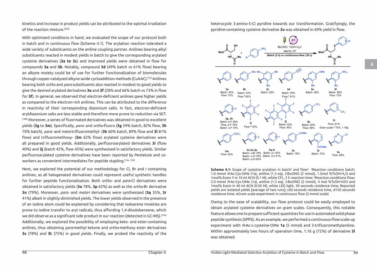
4
98 Chapter 4 Visible-Light-Mediated Selective Arylation of Cysteine in Batch and Flow 99
kinetics and increase in product yields can be attributed to the optimal irradiation
of the reaction mixture.[20a]
With optimized conditions in hand, we evaluated the scope of our protocol both
in batch and in continuous flow (Scheme 4.1). The arylation reaction tolerated a
wide variety of substituents on the aniline coupling partner. Anilines bearing alkyl
substituents reacted in modest yields in batch to give the corresponding arylated
cysteine derivatives (3a to 3c) and improved yields were obtained in flow for
compounds 3a and 3b. Notably, compound 3d (49% batch vs 61% flow) bearing
an alkyne moiety could be of use for further functionalization of biomolecules
through copper-catalyzed alkyne-azide cycloaddition methods (CuAAC).[23] Anilines
bearing both ortho and para substituents also reacted in modest to good yields to
give the desired arylated derivatives 3e and 3f (28% and 66% batch vs 73% in flow
for 3f). In general, we observed that electron-deficient anilines gave higher yields
as compared to the electron-rich anilines. This can be attributed to the difference
in reactivity of their corresponding diazonium salts. In fact, electron-deficient
aryldiazonium salts are less stable and therefore more prone to reduction via SET.[18b] Moreover, a series of fluorinated derivatives was obtained in good to excellent
yields (3g to 3m). Specifically, para- and ortho-fluoro (3g 59% batch, 82% flow, 3h
70% batch), para- and meta-trifluoromethyl- (3k 60% batch, 89% flow and 3l 81%
flow) and trifluoromethoxy- (3m 62% flow) arylated cysteine derivatives were
all prepared in good yields. Additionally, perfluoroarylated derivatives 3i (flow
40%) and 3j (batch 42%, flow 45%) were synthesized in satisfactory yields. Similar
perfluoroarylated cysteine derivatives have been reported by Pentelute and co-
workers as convenient intermediates for peptide stapling.[14a, 14b]
Next, we explored the potential of our methodology for Cl, Br and I containing
anilines, as all halogenated derivatives could represent useful synthetic handles
for further peptide functionalization. Both ortho- and para-Cl derivatives were
obtained in satisfactory yields (3o 78%, 3p 62%) as well as the ortho-Br derivative
3n (79%). Moreover, para- and meta-I derivatives were synthesized (3q 35%, 3r
41%) albeit in slightly diminished yields. The lower yields observed in the presence
of an iodine atom could be explained by considering that iodoarene moieties are
prone to iodine transfer to aryl radicals, thus affording 1,4-diiodobenzene, which
we did observe as a significant side product in our reaction (detected in GC-MS).[19e]
Additionally, we explored the possibility of employing keto- and ester-containing
anilines, thus obtaining para-methyl ketone and ortho-methoxy ester derivatives
3s (78%) and 3t (75%) in good yields. Finally, we probed the reactivity of the
heterocycle 3-amino-5-Cl pyridine towards our transformation. Gratifyingly, the
pyridine-containing cysteine derivative 3u was obtained in 69% yield in flow.
Scheme 4.1: Scope of cysteine arylation in batcha and flowb. aReaction conditions batch: 1.0 mmol N-Ac-Cys-OMe (1a), aniline (1.3 eq), t-BuONO (2 mmol), 1.5mol %TsOH∙H2O and 1mol% Eosin Y in 10 ml ACN (0.1 M), white CFL, 2 h reaction time; bReaction conditions flow: 2.0 mmol N-Ac-Cys-OMe (1a), aniline (1.3 eq), t-BuONO (2 mmol), 4 mol %TsOH∙H2O and 1mol% Eosin in 40 ml ACN (0.05 M), white LED light, 30 seconds residence time; Reported yields are isolated yields [average of two runs]; c60 seconds residence time, d150 seconds residence time. eGram scale experiment in continuous flow (5 mmol scale)
Owing to the ease of scalability, our flow protocol could be easily employed to
obtain arylated cysteine derivatives on gram scales. Consequently, this notable
feature allows one to prepare sufficient quantities for use in automated solid phase
peptide synthesis (SPPS). As an example, we performed a continuous-flow scale-up
experiment with N-Ac-L-cysteine-OMe 1a (5 mmol) and 3-trifluoromethylaniline.
Within approximately two hours of operation time, 1.16 g (72%) of derivative 3l
was obtained.
tBuONO, TsOH·H2OMeCN, RT
Batch (2 h) or continuous-flow (30 s)HN
O SH
MeO
Me
O
NH2
R
+HN
O S
MeO
Me
O
R
3aBatch: 50%Flow: 72%
3bBatch: 33%Flow:d 62%
tBu
3cBatch: 29%
Me
Me
Me
3dBatch: 49%Flow:c 61%
3eBatch: 28%
OMe
3fBatch: 66%Flow: 73%
NO2
Me Me
3g, 3hBatch: p-F 59%Flow: p-F 79%Batch: o-F 70%
3iFlow:d 40%
F
3jBatch: 42%Flow: 45%
3kBatch: 60%Flow: 89%
CF3
3lFlow: 81%
Gram scale:e 75%, 1.16g
F
3mFlow: 62%
3n,3o,3pBatch: o-Br 79%Batch: o-Cl 78%Batch: p-Cl 62%
OCF3
CF3
F
F
F
F
F
F
F
F
F
F
F
F
3q,3rBatch: p-I 35%Batch: m-I 41%
3sBatch: 78%
IN
3uFlow: 69%
Cl
F
COMe
3tBatch: 75%
COOMe
X
EY
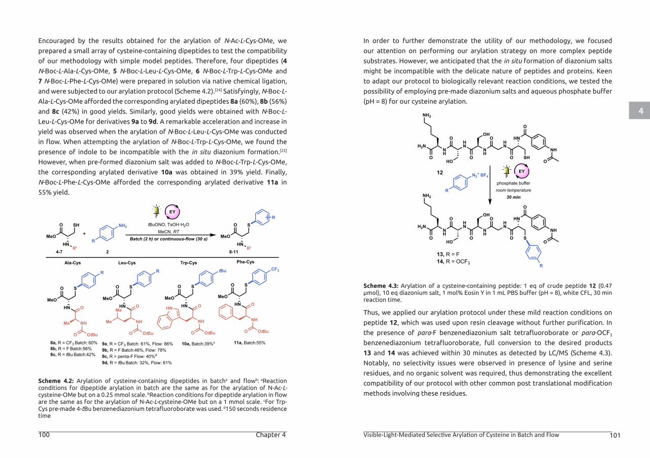
4
100 Chapter 4 Visible-Light-Mediated Selective Arylation of Cysteine in Batch and Flow 101
Encouraged by the results obtained for the arylation of N-Ac-L-Cys-OMe, we
prepared a small array of cysteine-containing dipeptides to test the compatibility
of our methodology with simple model peptides. Therefore, four dipeptides (4
N-Boc-L-Ala-L-Cys-OMe, 5 N-Boc-L-Leu-L-Cys-OMe, 6 N-Boc-L-Trp-L-Cys-OMe and
7 N-Boc-L-Phe-L-Cys-OMe) were prepared in solution via native chemical ligation,
and were subjected to our arylation protocol (Scheme 4.2).[24] Satisfyingly, N-Boc-L-
Ala-L-Cys-OMe afforded the corresponding arylated dipeptides 8a (60%), 8b (56%)
and 8c (42%) in good yields. Similarly, good yields were obtained with N-Boc-L-
Leu-L-Cys-OMe for derivatives 9a to 9d. A remarkable acceleration and increase in
yield was observed when the arylation of N-Boc-L-Leu-L-Cys-OMe was conducted
in flow. When attempting the arylation of N-Boc-L-Trp-L-Cys-OMe, we found the
presence of indole to be incompatible with the in situ diazonium formation.[25]
However, when pre-formed diazonium salt was added to N-Boc-L-Trp-L-Cys-OMe,
the corresponding arylated derivative 10a was obtained in 39% yield. Finally,
N-Boc-L-Phe-L-Cys-OMe afforded the corresponding arylated derivative 11a in
55% yield.
Scheme 4.2: Arylation of cysteine-containing dipeptides in batcha and flowb: aReaction conditions for dipeptide arylation in batch are the same as for the arylation of N-Ac-L-cysteine-OMe but on a 0.25 mmol scale. bReaction conditions for dipeptide arylation in flow are the same as for the arylation of N-Ac-L-cysteine-OMe but on a 1 mmol scale. cFor Trp-Cys pre-made 4-tBu benzenediazonium tetrafluoroborate was used. d150 seconds residence time
In order to further demonstrate the utility of our methodology, we focused
our attention on performing our arylation strategy on more complex peptide
substrates. However, we anticipated that the in situ formation of diazonium salts
might be incompatible with the delicate nature of peptides and proteins. Keen
to adapt our protocol to biologically relevant reaction conditions, we tested the
possibility of employing pre-made diazonium salts and aqueous phosphate buffer
(pH = 8) for our cysteine arylation.
Scheme 4.3: Arylation of a cysteine-containing peptide: 1 eq of crude peptide 12 (0.47 μmol), 10 eq diazonium salt, 1 mol% Eosin Y in 1 mL PBS buffer (pH = 8), white CFL, 30 min reaction time.
Thus, we applied our arylation protocol under these mild reaction conditions on
peptide 12, which was used upon resin cleavage without further purification. In
the presence of para-F benzenediazonium salt tetrafluoroborate or para-OCF3
benzenediazonium tetrafluoroborate, full conversion to the desired products
13 and 14 was achieved within 30 minutes as detected by LC/MS (Scheme 4.3).
Notably, no selectivity issues were observed in presence of lysine and serine
residues, and no organic solvent was required, thus demonstrating the excellent
compatibility of our protocol with other common post translational modification
methods involving these residues.
HN
O SH
MeO
R'HN
O S
MeO
R'
R
HN
O S
MeO
8a, R = CF3 Batch: 60%8b, R = F Batch:56%8c, R = tBu Batch:42%
9a, R = CF3 Batch: 61%, Flow: 86%9b, R = F Batch:46%, Flow: 78%9c, R = penta-F Flow: 40%d
9d, R = tBu Batch: 32%, Flow: 61%
Ala-Cys Leu-Cys
O
NHMe
OtBuO
R
HN
O S
MeOO
NH
OtBuO
R
4-7 8-11
Me
Me
NH2
R
2
+
tBuONO, TsOH·H2OMeCN, RT
Batch (2 h) or continuous-flow (30 s)
HN
O S
MeO
10a, Batch:39%c 11a, Batch:55%
O
NH
OtBuO
tBu
HN
O S
MeOO
NH
OtBuO
CF3Trp-Cys Phe-Cys
HN
EY
12
13, R = F14, R = OCF3
N2+ BF4-
Rphosphate bufferroom temperature
30 min
HN
O SH
HN
O
NH
O
OH
HN
O
HO
NH
O
NH2
H2N
O
NH
O
HN
O S
HN
O
NH
O
OH
HN
O
HO
NH
O
NH2
H2N
O
NH
O
R
EY
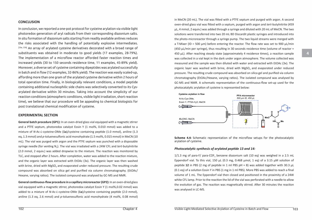
4
102 Chapter 4 Visible-Light-Mediated Selective Arylation of Cysteine in Batch and Flow 103
CONCLUSION
In conclusion, we reported a one-pot protocol for cysteine arylation via visible light
photoredox generation of aryl radicals from their corresponding diazonium salts.
In situ formation of diazonium salts starting from readily available anilines reduces
the risks associated with the handling of potentially explosive intermediates.[20a, 22b] An array of arylated cysteine derivatives decorated with a broad range of
substituents was obtained in moderate to good yields (17 examples, 28-79%).
The implementation of a microflow reactor afforded faster reaction times and
increased yields (30 to 150 seconds residence time, 11 examples, 45-89% yield).
Moreover, a diverse set of cysteine containing dipeptides was arylated successfully
in batch and in flow (12 examples, 32-86% yield). The reaction was easily scaled-up,
affording more than one gram of the arylated cysteine derivative within 2 hours of
total operation time. Finally, in biologically relevant conditions, a model peptide
containing additional nucleophilic side chains was selectively converted to its Cys-
arylated derivative within 30 minutes. Taking into account the simplicity of our
reaction conditions (atmospheric conditions, visible light irradiation, short reaction
time), we believe that our procedure will be appealing to chemical biologists for
post translational chemical modification of cysteine.
EXPERIMENTAL SECTION
General batch procedure (GP1): In an oven-dried glass vial equipped with a magnetic stirrer and a PTFE septum, photoredox catalyst Eosin Y (1 mol%, 0.010 mmol) was added to a mixture of N-Ac-L-cysteine-OMe (1a)/cysteine containing peptide (1.0 mmol), aniline (1.3 eq, 1.3 mmol) and p-toluenesulfonic acid monohydrate (1.5 mol%, 0.015 mmol) in MeCN (10 mL). The vial was purged with argon and the PTFE septum was punched with a disposable syringe needle (for venting N2). The vial was irradiated with a 24W CFL and tert-butylnitrite (2.0 mmol, 2 equiv.) was added dropwise to the mixture. The reaction was monitored by TLC, and stopped after 2 hours. After completion, water was added to the reaction mixture, and the organic layer was extracted with EtOAc (3x). The organic layer was then washed with brine, dried with MgSO4 and evaporated under reduced pressure. The resulting crude compound was absorbed on silica gel and purified via column chromatography. (EtOAc/Hexane, varying ratios). The isolated compound was analysed by GC-MS and NMR.
General continuous-flow procedure in a capillary microreactor (GP2): In an oven-dried glass vial equipped with a magnetic stirrer, photoredox catalyst Eosin Y (1 mol%,0.02 mmol) was added to a mixture of N-Ac-L-cysteine-OMe (1a)/cysteine containing peptide (2.0 mmol), aniline (1.3 eq, 2.6 mmol) and p-toluenesulfonic acid monohydrate (4 mol%, 0.08 mmol)
in MeCN (20 mL). The vial was fitted with a PTFE septum and purged with argon. A second oven-dried glass vial was fitted with a septum, purged with argon and tert-butylnitrite (459 μL, 4 mmol, 2 equiv.) was added through a syringe and diluted with 20 mL of MeCN. The two solutions were transferred into two 20 mL BD Discardit plastic syringes and introduced into the photo-microreactor through a syringe pump. The two liquid streams were merged with a T-Mixer (ID = 500 μm) before entering the reactor. The flow rate was set to 900 μL/min (450 μL/min per syringe), thus resulting in 30 seconds residence time (volume of reactor = 450 μL). After reaching steady state (approximately 4 residence times), a reaction sample was collected in a vial kept in the dark under argon atmosphere. The volume collected was measured and the sample was then diluted with water and extracted with EtOAc (3x). The organic layer was washed with brine, dried with MgSO4 and evaporated under reduced pressure. The resulting crude compound was absorbed on silica gel and purified via column chromatography (EtOAc/Hexane, varying ratios). The isolated compound was analysed by GC-MS and NMR. A schematic representation of the continuous-flow set-up used for the photocatalytic arylation of cysteine is represented below:
Scheme 4.4: Schematic representation of the microflow setups for the photocatalytic arylation of cysteine.
Photocatalytic synthesis of arylated peptide 13 and 14:
1/1.3 mg of para-F/ para-COF3 benzene diazonium salt (10 eq) was weighed in a 2.5 mL Eppendorf vial. To this vial, 150 μL (0.3 mg, 0.468 μmol, 1 eq) of a 3.15 μM solution of peptide 12 in PBS (2 mg of peptide in 1 ml PBS pH = 8) was added together with 30.3 μL (0.1 eq) of a solution Eosin Y in PBS (1 mg in 1 ml PBS). More PBS was added to reach a final volume of 1 mL. The Eppendorf vial then closed and positioned in the proximity of a 24W white CFL lamp. Prior to the reaction the lid of the vial was perforated with a needle to allow the evolution of gas. The reaction was magnetically stirred. After 30 minutes the reaction was analysed in LC-MS.
PFA microreactor500 µm ID, 450 µL
tBuONO, MeCN
N-Ac-Cys-OMe,Eosin Y, PTSA H2O, MeCN
HN
O S
MeOMe
O
Cysteine arylation in flow
R
4
104 Chapter 4 Visible-Light-Mediated Selective Arylation of Cysteine in Batch and Flow 105
Preparation of starting materials:
Synthesis of peptides 4, 5, 6 and 7 via native chemical ligation: the dipeptides used as starting materials for the synthesis of derivatives 8 to 11 were prepared through a two-step procedure adapted from literature.2
Step 1: Formation of the thioester derivative: L-Boc-Ala-OH or L-Boc-Leu-OH or L-Boc-Trp-OH or L-Boc-Phe-OH (1.0 equiv.) and DCM or ethyl acetate (0.5 mmol/mL) were added to an oven-dried flask and placed in an ice bath (0°C). Then, DCC (1 equiv.) and HOBt•H2O (1 equiv.) were added together with thiophenol (1 equiv.). The flask was closed with a PTFE septum and the reaction mixture was placed under argon atmosphere. The reaction was checked for completion by TLC (4 -24 hours). The reaction mixture was washed with HCl (1M), NaHCO3 (sat) and brine. The organic layer was dried with MgSO4.The crude was absorbed on silica gel and purified with PE:EtOAC 7:1. Purification by column chromatography (DCM:MeOH 9:1 + 1% acetic acid) afforded the desired thioester intermediates.
Step 2: Native chemical ligation: L-Cysteine methyl ester HCl (1.0 equiv.) and the thioester derivative obtained from the previous step (1.0 equiv.) were added to MeOH (0.25 mmol/mL) in an oven-dried flask kept under argon atmosphere and closed with a PTFE septum. Next tributylphopshine (0.6 equiv.) was added and the reaction mixture was stirred at r.t. until completion (24 hours). The crude was evaporated under vacuo, and re-dissolved in EtOAc. The organic layer was extracted with H2O (3 times) and with brine (3 times). The organic layer was then dried with MgSO4 and concentrated on silica gel under vacuo. Purification by column chromatography (DCM:MeOH 9:1 + 1% acetic acid) afforded the desired dipeptides Boc-Ala-Cys-OMe 4 (overall yield 37%), Boc-Leu-Cys-OMe 5 (overall yield 39%), Boc-Trp-Cys-OMe 6 (overall yield 77%) and Boc-Phe-Cys-OMe 7 (overall yield, 20%).
Synthesis of peptide 12 (starting material): Automated peptide synthesis were performed on a fully-automated SYRO Multiple Peptide Synthesizer robot, equipped with a vortexing unit for the 24-reactor block (MultiSynTech GmbH). Reactions were open to the atmosphere and executed at ambient temperature. Peptide 12 was synthesized using the Fmoc/tBu strategy with HBTU/DIPEA-mediated couplings. Peptide sequence synthesized ABA-CGSSK-CONH2. After the final Fmoc deprotection step, the peptide was manually cleaved from the resin. Cleavage cocktail (500 μL – 1 mL of 95% TFA, 2.5% TIPS and 2.5% H2O) was added to peptide resin, and the reaction was shaken at r.t. for 2 h. Cleavage cocktail containing peptide was precipitated into cold ether and centrifuged (10 mins, 10 kprm). Ether was poured off, and the pellet was re-suspended in fresh cold ether and centrifuged (10 mins, 10 kprm). The resulting pellet peptide was dried on an oil pump. Peptide 12 was then analysed by LC/MS and employed for the reaction without further purification.
COMPOUND CHARACTERIZATION
Methyl N-acetyl-S-phenyl-L-cysteinate (3a) was made according to GP1 on a 1.0 mmol scale. The crude product was purified by flash chromatography (petroleum ether: ethyl acetate 1:1) yielding 126.4 mg (0.50 mmol, 50 %) of 3a as a yellow oil. The reaction according to GP2 on a 1.825 mmol scale afforded 328.3 mg (1.30 mmol, 72%) of 3a within 30 seconds residence time. 1H NMR (400 MHz, Chloroform-d) δ 7.41 (d, J = 8.1 Hz, 2H), 7.32 – 7.27 (m, 2H), 7.23 (d, J = 7.6 Hz, 1H), 6.20 (d, J = 6.6 Hz, 1H), 4.92 – 4.79 (m, 1H), 3.56 (s, 3H), 3.52 – 3.33 (m, 2H), 1.87 (s, 3H). 13C NMR (101 MHz, CDCl3) δ 170.8, 169.9, 134.8, 131.2, 129.2, 127.3, 52.6, 52.5, 36.6, 23.0. HRMS (ESI) m/z [M+H]+ calculated for C12H16NO3S: 254.0846, found 254.0849.
Methyl N-acetyl-S-(4-tert-butylphenyl)-L-cysteinate (3b) was made according to GP1 on a 1.0 mmol scale. The crude product was purified by flash chromatography (petroleum ether: ethyl acetate 1:1) yielding 101.4 (0.33 mmol, 33 %) of 3b as a yellow oil. The reaction according to GP2 on a 1.75 mmol scale afforded 335.6 mg (1.09 mmol, 62%) of 3b within 150 seconds residence time. 1H NMR (400 MHz, Chloroform-d) δ 7.38 – 7.29 (m, 4H), 6.18 (d, J = 7.0 Hz, 1H), 4.85 (dt, J = 7.6, 4.4 Hz, 1H), 3.54 (s, 3H), 3.47 – 3.29 (m, 2H), 1.84 (s, 3H), 1.29 (s, 9H). 13C NMR (101 MHz, CDCl3) δ 170.8, 169.9, 150.7, 131.5, 131.1, 126.2, 52.6, 52.5, 36.9, 34.6, 31.3, 23.0. HRMS (ESI) m/z [M + H]+ calculated for C16H24NO3S: 310.1472, found 310.1479.
Methyl N-acetyl-S-mesityl-L-cysteinate (3c) was made according to GP1 on a 1.0 mmol scale. The crude product was purified by flash chromatography (petroleum ether: ethyl acetate 1:1) yielding 159.9 mg (0.59 mmol, 59 %) of 3c as a yellow oil.1H NMR (400 MHz, Chloroform-d) δ 6.91 (s, 2H), 6.17 (d, J = 6.72 Hz, 1H), 4.82 – 4.73 (m, 1H), 3.59 (s, 3H), 3.29 – 3.07 (m, 2H), 2.47 (s, 6H), 2.24 (s, 3H), 1.91 (s, 3H). 13C NMR (101 MHz, Chloroform-d) δ 171.1, 169.8, 142.5, 138.5, 129.4, 129.0, 52.8, 52.7, 36.6, 23.1, 21.9, 21.1. HRMS (ESI) m/z [M + H]+ calculated for C15H22NO3S: 296.1315, found 296.1317
Methyl N-acetyl-S-(4-ethynylphenyl)-L-cysteinate (3d) was made according to GP1 on a 1.0 mmol scale. The crude product was purified by flash chromatography (petroleum ether: ethyl acetate 1:1) yielding 136.4 (0.49 mmol, 49 %) of 3d as a yellow oil. The reaction according to GP2 on a 1.75 mmol scale afforded 296.3 mg (1.07 mmol, 61%) of 3d within 60 seconds residence time. 1H NMR (399 MHz, Chloroform-d) δ 7.42 – 7.30 (m, 4H), 6.24 (d, J = 7.4 Hz, 1H), 4.87 (dt, J = 7.4, 4.5 Hz, 1H), 3.59 (s, 3H), 3.44 (ddd, J = 57.0, 14.3, 4.5 Hz, 2H), 3.10 (s, 1H), 1.90 (s, 3H). 13C NMR (100 MHz, Chloroform-d) δ 170.7, 169.9, 136.4, 132.7, 129.9, 120.6, 83.0, 78.2, 77.5, 77.2, 76.8, 52.8, 52.4, 35.9, 23.1. HRMS (ESI) m/z [M + H]+ calculated for C14H16NO3S: 278.0846, found 278.0853
4
106 Chapter 4 Visible-Light-Mediated Selective Arylation of Cysteine in Batch and Flow 107
Methyl N-acetyl-S-(4-methoxy-2-methylphenyl)-L-cysteinate (3e) was made according to GP1 on a 1.0 mmol scale. The crude product was purified by flash chromatography (petroleum ether: ethyl acetate 1:1) yielding 83.4 mg (0.28 mmol, 28 %) of 3e as a yellow oil. 1H NMR (399 MHz, Chloroform-d) δ 7.37 (d, J = 8.54 Hz, 1H), 6.76 (d, J = 2.77 Hz, 1H), 6.69 (dd, J = 8.53, 2.84 Hz, 1H), 6.18 (d, J = 6.91 Hz, 1H), 4.79 (dt, J = 7.54, 4.58 Hz, 1H), 3.77 (s, 3H), 3.57 (s, 3H), 3.34 – 3.16 (m, 2H), 2.43 (s, 3H), 1.91 (s, 3H). 13C NMR (100 MHz, Chloroform-d) δ 171.0, 169.8, 159.7, 142.4, 135.4, 124.0, 116.2, 112.2, 55.4, 52.6, 52.5, 37.2, 23.1, 21.2. HRMS (ESI) m/z [M + H]+ calculated for C14H20NO4S: 298.1108, found 298.1113
Methyl N-acetyl-S-(2-methyl-4-nitrophenyl)-L-cysteinate (3f) was made according to GP1 on a 1.0 mmol scale. The crude product was purified by flash chromatography (petroleum ether: ethyl acetate 1:1) yielding 206.2 (0.66 mmol, 66 %) of 3f as a yellow oil. The reaction according to GP2 on a 1.85 mmol scale afforded 421.4 mg (1.35 mmol, 73%) of 3f within 30 seconds residence time. 1H NMR (399 MHz, Chloroform-d) δ 7.98 (d, J = 11.02 Hz, 2H), 7.36 (d, J = 8.42 Hz, 1H), 6.45 (d, J = 6.02 Hz, 1H), 5.03 – 4.69 (m, 1H), 3.69 (s, 3H), 3.65 – 3.34 (m, 2H), 2.36 (s, 3H), 1.95 (s, 3H). 13C NMR (100 MHz, Chloroform-d) δ 170.6, 170.0, 145.4, 144.8, 137.7, 126.0, 124.7, 121.6, 53.1, 52.0, 34.2, 23.2, 20.5. HRMS (ESI) m/z [M + H]+ calculated for C13H17N2O5S: 313.0853, found 313.0860
Methyl N-acetyl-S-(4-fluorophenyl)-L-cysteinate (3g) was made according to GP1 on a 1.0 mmol scale. The crude product was purified by flash chromatography (petroleum ether: ethyl acetate 1:1) yielding 159.9 mg (0.59 mmol, 59%) of 3g as a yellow oil. The reaction according to GP2 on a 1.85 mmol scale afforded 396.1 mg (1.46 mmol, 79%) of 3g within 30 seconds residence time. 1H NMR (400 MHz, Chloroform-d) δ 7.51 – 7.36 (m, 2H), 7.10 – 6.94 (m, 2H), 6.20 (s, 1H), 4.83 (dt, J = 7.50, 4.55 Hz, 1H), 3.58 (s, 3H), 3.43 (dd, J = 14.28, 4.56 Hz, 1H), 3.30 (dd, J = 14.28, 4.56 Hz, 1H), 1.92 (s, 3H). 13C NMR (101 MHz, Chloroform-d) δ 170.8, 169.8, 162.3 (d, J = 248.00 Hz), 134.0 (d, J = 8.13 Hz), 129.8 (d, J = 3.37 Hz), 116.3 (d, J = 21.94 Hz), 52.6, 52.4, 37.7, 23.1. 19F NMR (376 MHz, Chloroform-d) δ -113.79 – -113.90 (m). HRMS (ESI) m/z [M+H]+ calculated for C12H15FNO3S: 272.0751, found 272.0755.
Methyl N-acetyl-S-(2-fluorophenyl)-L-cysteinate (3h) was made according to GP1 on a 1.0 mmol scale. The crude product was purified by flash chromatography (petroleum ether: ethyl acetate 1:1) yielding 189.9 mg (0.70 mmol, 70%) of 3h as a yellow oil. 1H NMR (400 MHz, Chloroform-d) δ 7.45 (td, J = 7.84, 1.76 Hz, 1H), 7.31 – 7.19 (m, 1H), 7.13 – 7.01 (m, 2H), 6.28 (d, J = 6.26 Hz, 1H), 5.14 – 4.59 (m, 1H), 3.54 (s, 3H), 3.40 (dd, J = 4.45, 3.27 Hz, 2H), 1.92 (s, 3H). 13C NMR (101 MHz, Chloroform-d) δ 170.7, 169.8, 162.3 (d, J = 246.57 Hz), 134.5, 129.9 (d, J = 8.02 Hz), 124.7 (d, J = 3.81 Hz), 121.4 (d, J = 17.47 Hz), 116.1 (d, J = 22.76 Hz), 52.6, 52.3, 36.0, 23.1. 19F NMR (376 MHz, Chloroform-d) δ -105.69 – -111.27 (m). HRMS (ESI) m/z [M+H]+ calculated for C12H15FNO3S: 272.0751, found 272.0750.
Methyl N-acetyl-S-(perfluorophenyl)-L-cysteinate (3i) was made according to GP2 on a 1.725 mmol scale. The crude product was purified by flash chromatography (petroleum ether: ethyl acetate 1:1) yielding 235.6 mg (0.67 mmol, 40%) of 3i as a yellow oil within 150 seconds residence time.
1H NMR (400 MHz, Chloroform-d) δ 6.35 (d, J = 6.21 Hz, 1H), 4.79 (dt, J = 7.11, 4.62 Hz, 1H), 3.67 (s, 3H), 3.51 – 3.24 (m, 2H), 2.00 (s, 3H). 13C NMR (101 MHz, Chloroform-d) δ 170.2, 169.7, 148.7, 146.4, 138.9, 132.8, 129.2, 111.1, 52.8, 52.0, 36.5, 22.9. 19F NMR (376 MHz, Chloroform-d) δ -131.69 (dd, J = 22.97, 8.69 Hz), -151.41 (t, J = 20.90 Hz), -160.52 (td, J = 22.39, 6.40 Hz). HRMS (ESI) m/z [M + H]+ calculated for C12H11F5NO3S: 344.0380, found 344.0377.
Methyl N-acetyl-S-(perfluoro-[1,1’-biphenyl]-4-yl)-L-cysteinate (3j) was made according to GP1 on a 1.0 mmol scale. The crude product was purified by flash chromatography (petroleum ether: ethyl acetate 1:1) yielding 206.4 mg (0.42 mmol, 42%) of 3j as a yellow oil. The reaction according to GP2 on a 1.875 mmol scale afforded 403.1 mg (0.84 mmol, 45%) of 3j within 30 seconds residence time. 1H NMR (399 MHz, Chloroform-d) δ 6.42 (d, J = 7.09 Hz, 1H), 4.87 (dt, J = 7.04, 4.36 Hz, 1H), 3.65 (s, 3H), 3.61 – 3.50 (m, 2H), 2.00 (s, 3H). 13C NMR (100 MHz, Chloroform-d) δ 170.2, 170.1, 148.4, 145.9, 143.3, 143.0, 142.8, 139.3, 136.9, 116.5, 52.9, 52.4, 36.1, 23.0. 19F NMR (376 MHz, Chloroform-d) δ -131.55 – -131.79 (m), -137.34 – -137.57 (m), -149.55 – -149.74 (m), -160.13 – -160.33 (m). HRMS (ESI) m/z [M + H]+ calculated for C18H11F9NO3S: 429.0310, found 429.0353.
Methyl N-acetyl-S-(4-trifluoromethylphenyl)-L-cysteinate (3k) was made according to GP1 on a 1.0 mmol scale. The crude product was purified by flash chromatography (petroleum ether: ethyl acetate 1:1) yielding 192.6 mg (0.60 mmol, 60%) of 3k as a yellow oil. The reaction according to GP2 on a 1.700 mmol scale afforded 511.2 mg (1.59 mmol, 89%) of 3k within 30 seconds residence time. 1H NMR (400 MHz, Chloroform-d) δ 7.51 (d, J = 8.27 Hz, 2H), 7.44 (d, J = 8.21 Hz, 2H), 6.38 (s, 1H), 4.87 (dt, J = 7.31, 4.70 Hz, 1H), 3.60 (s, 3H), 3.55 (dd, J = 14.19, 4.78 Hz, 1H), 3.39 (dd, J = 14.18, 4.65 Hz, 1H), 1.88 (s, 3H). 13C NMR (101 MHz, Chloroform-d) δ 170.5, 169.9, 152.8, 140.3, 129.2, 125.7 (q, J = 3.81 Hz), 125.2, 52.6, 52.2, 35.2, 22.8. 19F NMR (376 MHz, Chloroform-d) δ -62.67. HRMS (ESI) m/z [M+H]+ calculated for C13H15F3NO3S: 322.0718, found 322.0724.
Methyl N-acetyl-S-(3-trifluoromethylphenyl)-L-cysteinate (3l) was made according to GP2 on a 1.775 mmol scale. The crude product was purified by flash chromatography (petroleum ether: ethyl acetate 1:1) yielding 518.9 mg (1.62 mmol, 81%) of 3l as a yellow oil within 30 seconds residence time. 1H NMR (400 MHz, Chloroform-d) δ 7.63 (s, 1H), 7.56 (d, J = 7.58 Hz, 1H), 7.43 (dt, J = 15.53, 7.84 Hz, 2H), 6.32 (s, 1H), 4.88 (dt, J = 7.36, 4.51 Hz, 1H), 3.58 (s, 1H), 3.54 (dd, J = 14.32, 4.74 Hz, 1H), 3.41 (dd, J = 14.25, 4.39 Hz, 1H), 1.91 (s, 3H).13C NMR (101
4
108 Chapter 4 Visible-Light-Mediated Selective Arylation of Cysteine in Batch and Flow 109
MHz, Chloroform-d) δ 170.7, 169.9, 136.7, 133.6, 131.6 (q, J = 32.51 Hz), 129.6, 127.0 (q, J = 3.86 Hz), 123.8 (q, J = 272.59 Hz), 123.7 (q, J = 3.76 Hz), 52.8, 52.4, 36.3, 23.1.19F NMR (188 MHz, Chloroform-d) δ -62.86. HRMS (ESI) m/z [M+H]+ calculated for C13H15F3NO3S: 322.0718, found 322.0730.
Methyl N-acetyl-S-(4-trifluoromethoxyphenyl)-L-cysteinate (3m) was made according to GP2 on a 1.85 mmol scale. The crude product was purified by flash chromatography (petroleum ether: ethyl acetate 1:1) yielding 389.0 mg (1.15 mmol, 62%) of 3m as a yellow oil within 30 seconds residence time. 1H NMR (400 MHz, Chloroform-d) δ 7.49 – 7.39 (m, 2H), 7.20 – 7.08 (m, 2H), 6.22 (d, J = 6.2 Hz, 1H), 4.94 – 4.78 (m, 1H), 3.57 (s, 3H), 3.56 – 3.28 (m, 2H), 1.89 (s, 3H). 13C NMR (101 MHz, Chloroform-d) δ 170.7, 169.9, 148.4, 133.7, 132.6, 121.8, 119.2, 52.6, 52.5, 36.9, 23.0; 19F NMR (188 MHz, Chloroform-d) δ -58.01. HRMS (ESI) m/z [M+H]+ calculated for C13H15F3NO4S: 338.0669, found 338.0673. HRMS (ESI) m/z [M+H]+ calculated for C13H15F3NO4S: 338.0674, found 338.0673.
Methyl N-acetyl-S-(2-bromophenyl)-L-cysteinate (3n) was made according to GP1 on a 1.0 mmol scale. The crude product was purified by flash chromatography (petroleum ether: ethyl acetate 1:1) yielding 254.7 mg (0.79 mmol, 79%) of 3n as a yellow oil. 1H NMR (400 MHz, Chloroform-d) δ 7.53 – 7.46 (m, 1H), 7.37 (dd, J = 7.85, 1.18 Hz, 1H), 7.24 – 7.17 (m, 1H), 7.01 (td, J = 7.87, 1.30 Hz, 1H), 6.32 (d, J = 6.17 Hz, 1H), 4.81 (dt, J = 7.47, 4.74 Hz, 1H), 3.57 (s, 3H), 3.39 (qd, J = 14.01, 4.75 Hz, 2H), 1.86 (s, 3H). 13C NMR (101 MHz, Chloroform-d) δ 170.7, 169.9, 135.9, 133.4, 131.5, 128.3, 128.0, 125.9, 52.8, 52.1, 35.9, 23.1. HRMS (ESI) m/z [M+H]+ calculated for C12H15BrNO3S: 331.9951, found 331.9951.
Methyl N-acetyl-S-(2-chlorophenyl)-L-cysteinate (3o) was made according to GP1 on a 1.0 mmol scale. The crude product was purified by flash chromatography (petroleum ether: ethyl acetate 1:1) yielding 224.7 mg (0.78 mmol, 78%) of 3o as a yellow oil. 1H NMR (400 MHz, Chloroform-d) δ 7.41 (ddd, J = 24.53, 7.74, 1.61 Hz, 2H), 7.18 (dtd, J = 20.96, 7.47, 1.57 Hz, 2H), 6.36 (d, J = 6.68 Hz, 1H), 4.86 (dt, J = 7.46, 4.71 Hz, 1H), 3.61 (s, 3H), 3.51 – 3.37 (m, 2H), 1.92 (s, 3H). 13C NMR (101 MHz, Chloroform-d) δ 170.7, 169.9, 135.6, 133.8, 131.9, 130.1, 128.3, 127.4, 52.7, 52.1, 35.5, 23.1. HRMS (ESI) m/z [M+H]+ calculated for C12H15ClNO3S: 288.0456, found 288.0463.
Methyl N-acetyl-S-(4-chlorophenyl)-L-cysteinate (3p) was made according to GP1 on a 1.0 mmol scale. The crude product was purified by flash chromatography (petroleum ether: ethyl acetate 1:1) yielding 117.6 mg (0.62 mmol, 62%) of 3p as a brown oil.1H NMR (399 MHz, Chloroform-d) δ 7.31 (d, J = 8.69 Hz, 2H), 7.24 (d, J = 8.69 Hz, 2H), 6.34 (d, J = 6.91 Hz, 1H), 4.82 (dt, J = 7.48, 4.71 Hz, 1H), 3.57 (s, 3H), 3.37 (ddd, J = 55.08, 14.21, 4.72 Hz, 2H), 1.89 (s, 3H). 13C NMR (100 MHz, Chloroform-d) δ 170.7, 169.9, 133.4, 133.2, 132.3, 129.2,
52.6, 52.3, 36.7, 23.0. HRMS (ESI) m/z [M+H]+ calculated for C12H15ClNO3S: 288.0456, found 288.0461.
Methyl N-acetyl-S-(4-iodophenyl)-L-cysteinate (3q) was made according to GP1 on a 1.0 mmol scale. The crude product was purified by flash chromatography (petroleum ether: ethyl acetate 1:1) yielding 133.2 mg (0.35 mmol, 35%) of 3q as a yellow oil. 1H NMR (399 MHz, Chloroform-d) δ 7.60 (d, J = 8.52 Hz, 2H), 7.12 (d, J = 8.52 Hz, 2H), 6.24 (d, J = 6.69 Hz, 1H), 4.84 (dt, J = 7.38, 4.59 Hz, 1H), 3.59 (s, 3H), 3.52 – 3.26 (m, 2H), 1.90 (s, 3H). 13C NMR (100 MHz, Chloroform-d) δ 170.7, 169.8, 138.1, 135.0, 132.5, 131.2, 129.2, 92.2, 52.7, 52.4, 36.4, 23.1. HRMS (ESI) m/z [M+H]+ calculated for C12H15INO3S: 379.9812, found 379.9817.
Methyl N-acetyl-S-(3-iodophenyl)-L-cysteinate (3r) was made according to GP1 on a 1.0 mmol scale. The crude product was purified by flash chromatography (petroleum ether: ethyl acetate 1:1) yielding 155.6 mg (0.41 mmol, 41%) of 3r as a yellow oil. 1H NMR (399 MHz, Chloroform-d) δ 7.73 (t, J = 1.65 Hz, 1H), 7.53 (dt, J = 7.85, 1.17 Hz, 1H), 7.34 (dt, J = 7.83, 1.26 Hz, 1H), 7.00 (t, J = 7.87 Hz, 1H), 6.29 (d, J = 5.83 Hz, 1H), 4.87 (dt, J = 7.32, 4.43 Hz, 1H), 3.60 (s, 3H), 3.41 (ddd, J = 51.73, 14.25, 4.44 Hz, 2H), 1.92 (s, 3H). 13C NMR (100 MHz, Chloroform-d) δ 170.7, 169.9, 138.8, 137.4, 136.0, 130.6, 129.7, 94.6, 52.8, 52.4, 36.3, 23.1. HRMS (ESI) m/z [M+H]+ calculated for C12H15INO3S: 379.9812, found 379.9824.
Methyl N-acetyl-S-(4-acetylphenyl)-L-cysteinate (3s) was made according to GP1 on a 1.0 mmol scale. The crude product was purified by flash chromatography (petroleum ether: ethyl acetate 1:1) yielding 230.6 mg (0.78 mmol, 78%) of 3s as a yellow oil. 1H NMR (400 MHz, Chloroform-d) δ 7.87 (d, J = 8.52 Hz, 2H), 7.40 (d, J = 8.52 Hz, 2H), 6.24 (d, J = 6.76 Hz, 1H), 4.91 (dt, J = 7.24, 4.67 Hz, 1H), 3.65 (s, 3H), 3.52 (ddd, J = 62.48, 14.15, 4.68 Hz, 2H), 2.57 (s, 3H), 1.91 (s, 3H). 13C NMR (101 MHz, Chloroform-d) δ 197.2, 170.7, 169.9, 142.3, 135.0, 129.0, 128.4, 52.9, 52.3, 34.9, 26.7, 23.1. HRMS (ESI) m/z [M+H]+ calculated for C14H18NO4S: 296.0951, found 296.0946.
Methyl (R)-2-((2-acetamido-3-methoxy-3-oxopropyl)thio)benzoate (3t) was made according to GP1 on a 1.0 mmol scale. The crude product was purified by flash chromatography (petroleum ether: ethyl acetate 1:1) yielding 233.6 mg (0.75 mmol, 75%) of 3t as a yellow oil. 1H NMR (399 MHz, Chloroform-d) δ 7.85 (d, J = 7.55 Hz, 1H), 7.46 (s, 2H), 7.25 – 7.19 (m, 1H), 6.55 (s, 1H), 5.02 – 4.72 (m, 1H), 3.92 (s, 3H), 3.68 (s, 3H), 3.57 – 3.36 (m, 2H), 1.91 (s, 3H). 13C NMR (101 MHz, Chloroform-d) δ 170.8, 170.1, 167.3, 138.3, 132.3, 130.9, 130.2, 128.6, 125.5, 52.8, 52.4, 51.9, 35.2, 23.0. HRMS (ESI) m/z [M+H]+ calculated for C14H18NO5S: 312.0900, found 312.0885.
Methyl N-acetyl-S-(6-chloropyridin-3-yl)-L-cysteinate (3u) was made according to GP2 on a 1.875 mmol scale. The crude product was purified by flash chromatography (petroleum ether: ethyl acetate 1:1) yielding 371.1 mg (1.29 mmol, 69%) of 3u as a yellow oil within 30
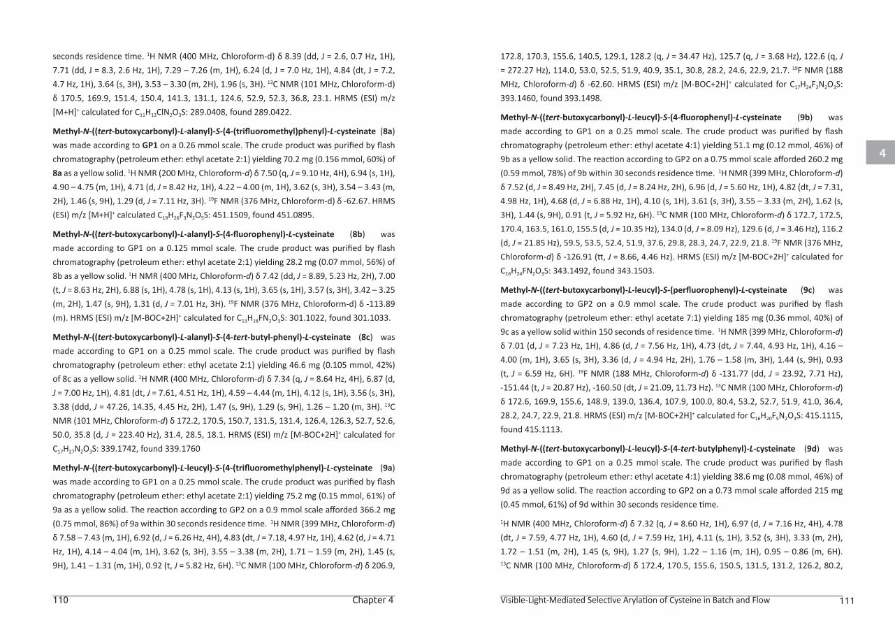
4
110 Chapter 4 Visible-Light-Mediated Selective Arylation of Cysteine in Batch and Flow 111
seconds residence time. 1H NMR (400 MHz, Chloroform-d) δ 8.39 (dd, J = 2.6, 0.7 Hz, 1H), 7.71 (dd, J = 8.3, 2.6 Hz, 1H), 7.29 – 7.26 (m, 1H), 6.24 (d, J = 7.0 Hz, 1H), 4.84 (dt, J = 7.2, 4.7 Hz, 1H), 3.64 (s, 3H), 3.53 – 3.30 (m, 2H), 1.96 (s, 3H). 13C NMR (101 MHz, Chloroform-d) δ 170.5, 169.9, 151.4, 150.4, 141.3, 131.1, 124.6, 52.9, 52.3, 36.8, 23.1. HRMS (ESI) m/z [M+H]+ calculated for C11H13ClN2O3S: 289.0408, found 289.0422.
Methyl-N-((tert-butoxycarbonyl)-L-alanyl)-S-(4-(trifluoromethyl)phenyl)-L-cysteinate (8a) was made according to GP1 on a 0.26 mmol scale. The crude product was purified by flash chromatography (petroleum ether: ethyl acetate 2:1) yielding 70.2 mg (0.156 mmol, 60%) of 8a as a yellow solid. 1H NMR (200 MHz, Chloroform-d) δ 7.50 (q, J = 9.10 Hz, 4H), 6.94 (s, 1H), 4.90 – 4.75 (m, 1H), 4.71 (d, J = 8.42 Hz, 1H), 4.22 – 4.00 (m, 1H), 3.62 (s, 3H), 3.54 – 3.43 (m, 2H), 1.46 (s, 9H), 1.29 (d, J = 7.11 Hz, 3H). 19F NMR (376 MHz, Chloroform-d) δ -62.67. HRMS (ESI) m/z [M+H]+ calculated C19H26F3N2O5S: 451.1509, found 451.0895.
Methyl-N-((tert-butoxycarbonyl)-L-alanyl)-S-(4-fluorophenyl)-L-cysteinate (8b) was made according to GP1 on a 0.125 mmol scale. The crude product was purified by flash chromatography (petroleum ether: ethyl acetate 2:1) yielding 28.2 mg (0.07 mmol, 56%) of 8b as a yellow solid. 1H NMR (400 MHz, Chloroform-d) δ 7.42 (dd, J = 8.89, 5.23 Hz, 2H), 7.00 (t, J = 8.63 Hz, 2H), 6.88 (s, 1H), 4.78 (s, 1H), 4.13 (s, 1H), 3.65 (s, 1H), 3.57 (s, 3H), 3.42 – 3.25 (m, 2H), 1.47 (s, 9H), 1.31 (d, J = 7.01 Hz, 3H). 19F NMR (376 MHz, Chloroform-d) δ -113.89 (m). HRMS (ESI) m/z [M-BOC+2H]+ calculated for C13H18FN2O3S: 301.1022, found 301.1033.
Methyl-N-((tert-butoxycarbonyl)-L-alanyl)-S-(4-tert-butyl-phenyl)-L-cysteinate (8c) was made according to GP1 on a 0.25 mmol scale. The crude product was purified by flash chromatography (petroleum ether: ethyl acetate 2:1) yielding 46.6 mg (0.105 mmol, 42%) of 8c as a yellow solid. 1H NMR (400 MHz, Chloroform-d) δ 7.34 (q, J = 8.64 Hz, 4H), 6.87 (d, J = 7.00 Hz, 1H), 4.81 (dt, J = 7.61, 4.51 Hz, 1H), 4.59 – 4.44 (m, 1H), 4.12 (s, 1H), 3.56 (s, 3H), 3.38 (ddd, J = 47.26, 14.35, 4.45 Hz, 2H), 1.47 (s, 9H), 1.29 (s, 9H), 1.26 – 1.20 (m, 3H). 13C NMR (101 MHz, Chloroform-d) δ 172.2, 170.5, 150.7, 131.5, 131.4, 126.4, 126.3, 52.7, 52.6, 50.0, 35.8 (d, J = 223.40 Hz), 31.4, 28.5, 18.1. HRMS (ESI) m/z [M-BOC+2H]+ calculated for C17H27N2O3S: 339.1742, found 339.1760
Methyl-N-((tert-butoxycarbonyl)-L-leucyl)-S-(4-(trifluoromethylphenyl)-L-cysteinate (9a) was made according to GP1 on a 0.25 mmol scale. The crude product was purified by flash chromatography (petroleum ether: ethyl acetate 2:1) yielding 75.2 mg (0.15 mmol, 61%) of 9a as a yellow solid. The reaction according to GP2 on a 0.9 mmol scale afforded 366.2 mg (0.75 mmol, 86%) of 9a within 30 seconds residence time. 1H NMR (399 MHz, Chloroform-d) δ 7.58 – 7.43 (m, 1H), 6.92 (d, J = 6.26 Hz, 4H), 4.83 (dt, J = 7.18, 4.97 Hz, 1H), 4.62 (d, J = 4.71 Hz, 1H), 4.14 – 4.04 (m, 1H), 3.62 (s, 3H), 3.55 – 3.38 (m, 2H), 1.71 – 1.59 (m, 2H), 1.45 (s, 9H), 1.41 – 1.31 (m, 1H), 0.92 (t, J = 5.82 Hz, 6H). 13C NMR (100 MHz, Chloroform-d) δ 206.9,
172.8, 170.3, 155.6, 140.5, 129.1, 128.2 (q, J = 34.47 Hz), 125.7 (q, J = 3.68 Hz), 122.6 (q, J = 272.27 Hz), 114.0, 53.0, 52.5, 51.9, 40.9, 35.1, 30.8, 28.2, 24.6, 22.9, 21.7. 19F NMR (188 MHz, Chloroform-d) δ -62.60. HRMS (ESI) m/z [M-BOC+2H]+ calculated for C17H24F3N2O3S: 393.1460, found 393.1498.
Methyl-N-((tert-butoxycarbonyl)-L-leucyl)-S-(4-fluorophenyl)-L-cysteinate (9b) was made according to GP1 on a 0.25 mmol scale. The crude product was purified by flash chromatography (petroleum ether: ethyl acetate 4:1) yielding 51.1 mg (0.12 mmol, 46%) of 9b as a yellow solid. The reaction according to GP2 on a 0.75 mmol scale afforded 260.2 mg (0.59 mmol, 78%) of 9b within 30 seconds residence time. 1H NMR (399 MHz, Chloroform-d) δ 7.52 (d, J = 8.49 Hz, 2H), 7.45 (d, J = 8.24 Hz, 2H), 6.96 (d, J = 5.60 Hz, 1H), 4.82 (dt, J = 7.31, 4.98 Hz, 1H), 4.68 (d, J = 6.88 Hz, 1H), 4.10 (s, 1H), 3.61 (s, 3H), 3.55 – 3.33 (m, 2H), 1.62 (s, 3H), 1.44 (s, 9H), 0.91 (t, J = 5.92 Hz, 6H). 13C NMR (100 MHz, Chloroform-d) δ 172.7, 172.5, 170.4, 163.5, 161.0, 155.5 (d, J = 10.35 Hz), 134.0 (d, J = 8.09 Hz), 129.6 (d, J = 3.46 Hz), 116.2 (d, J = 21.85 Hz), 59.5, 53.5, 52.4, 51.9, 37.6, 29.8, 28.3, 24.7, 22.9, 21.8. 19F NMR (376 MHz, Chloroform-d) δ -126.91 (tt, J = 8.66, 4.46 Hz). HRMS (ESI) m/z [M-BOC+2H]+ calculated for C16H24FN2O3S: 343.1492, found 343.1503.
Methyl-N-((tert-butoxycarbonyl)-L-leucyl)-S-(perfluorophenyl)-L-cysteinate (9c) was made according to GP2 on a 0.9 mmol scale. The crude product was purified by flash chromatography (petroleum ether: ethyl acetate 7:1) yielding 185 mg (0.36 mmol, 40%) of 9c as a yellow solid within 150 seconds of residence time. 1H NMR (399 MHz, Chloroform-d) δ 7.01 (d, J = 7.23 Hz, 1H), 4.86 (d, J = 7.56 Hz, 1H), 4.73 (dt, J = 7.44, 4.93 Hz, 1H), 4.16 – 4.00 (m, 1H), 3.65 (s, 3H), 3.36 (d, J = 4.94 Hz, 2H), 1.76 – 1.58 (m, 3H), 1.44 (s, 9H), 0.93 (t, J = 6.59 Hz, 6H). 19F NMR (188 MHz, Chloroform-d) δ -131.77 (dd, J = 23.92, 7.71 Hz), -151.44 (t, J = 20.87 Hz), -160.50 (dt, J = 21.09, 11.73 Hz). 13C NMR (100 MHz, Chloroform-d) δ 172.6, 169.9, 155.6, 148.9, 139.0, 136.4, 107.9, 100.0, 80.4, 53.2, 52.7, 51.9, 41.0, 36.4, 28.2, 24.7, 22.9, 21.8. HRMS (ESI) m/z [M-BOC+2H]+ calculated for C16H20F5N2O3S: 415.1115, found 415.1113.
Methyl-N-((tert-butoxycarbonyl)-L-leucyl)-S-(4-tert-butylphenyl)-L-cysteinate (9d) was made according to GP1 on a 0.25 mmol scale. The crude product was purified by flash chromatography (petroleum ether: ethyl acetate 4:1) yielding 38.6 mg (0.08 mmol, 46%) of 9d as a yellow solid. The reaction according to GP2 on a 0.73 mmol scale afforded 215 mg (0.45 mmol, 61%) of 9d within 30 seconds residence time.
1H NMR (400 MHz, Chloroform-d) δ 7.32 (q, J = 8.60 Hz, 1H), 6.97 (d, J = 7.16 Hz, 4H), 4.78 (dt, J = 7.59, 4.77 Hz, 1H), 4.60 (d, J = 7.59 Hz, 1H), 4.11 (s, 1H), 3.52 (s, 3H), 3.33 (m, 2H), 1.72 – 1.51 (m, 2H), 1.45 (s, 9H), 1.27 (s, 9H), 1.22 – 1.16 (m, 1H), 0.95 – 0.86 (m, 6H). 13C NMR (100 MHz, Chloroform-d) δ 172.4, 170.5, 155.6, 150.5, 131.5, 131.2, 126.2, 80.2,
4
112 Chapter 4 Visible-Light-Mediated Selective Arylation of Cysteine in Batch and Flow 113
64.3, 52.4, 41.0, 36.9, 34.6, 31.3, 28.4, 25.3, 24.7, 23.1, 21.8. HRMS (ESI) m/z [M-BOC+2H]+ calculated for C20H33N2O3S: 381.2212, found 381.2244.
Methyl-N-((tert-butoxycarbonyl)-L-tryptophyl)-S-(4-tert-butylphenyl)-L-cysteinate (10a) was made according to GP1 on a 0.25 mmol scale. The crude product was purified by flash chromatography (petroleum ether: ethyl acetate 2:1) yielding 55.6 mg (0.098 mmol, 39%) of 10a as a yellow solid.
1H NMR (400 MHz, Chloroform-d) δ 8.34 (s, 1H), 7.66 (d, J = 9.42 Hz, 1H), 7.37 (d, J = 8.06 Hz, 1H), 7.31 – 7.18 (m, 5H), 7.14 (t, J = 7.45 Hz, 1H), 7.09 (s, 1H), 6.71 (d, J = 7.41 Hz, 1H), 5.11 (s, 1H), 4.80 – 4.67 (m, 1H), 4.46 (s, 1H), 3.44 (s, 3H), 3.35 – 3.13 (m, 4H), 1.47 (s, 9H), 1.29 (s, 9H). 13C NMR (101 MHz, Chloroform-d) δ 171.5, 170.3, 161.7, 150.6, 143.0, 132.6, 131.4, 131.0, 129.5, 127.8, 126.2, 123.3, 122.4, 119.9, 119.0, 111.3, 52.4, 52.2, 37.1, 34.7, 31.3, 28.5, 22.1. HRMS (ESI) m/z [M-BOC+2H]+ calculated for C25H32N3O3S: 454.2164, found 454.2161.
Methyl-N-((tert-butoxycarbonyl)-L-tryptophyl)-S-(4-tert-butylphenyl)-L-cysteinate (11a) was made according to GP1 on a 0.5 mmol scale. The crude product was purified by flash chromatography (petroleum ether: ethyl acetate 4:1) yielding 144.7 mg (0.28 mmol, 55%) of 11a as a yellow solid.
1H NMR (400 MHz, Chloroform-d) δ 7.53 (d, J = 8.14 Hz, 2H), 7.44 (d, J = 8.20 Hz, 2H), 7.31 (q, J = 8.24, 7.55 Hz, 3H), 7.22 (d, J = 6.23 Hz, 2H), 6.80 (d, J = 6.68 Hz, 1H), 4.91 – 4.78 (m, 2H), 4.46 – 4.27 (m, 1H), 3.60 (s, 3H), 3.44 (qd, J = 14.07, 4.99 Hz, 2H), 3.18 – 2.92 (m, 2H), 1.43 (d, J = 2334.78 Hz, 9H). 19F NMR (376 MHz, Chloroform-d) δ -62.54. 13C NMR (101 MHz, Chloroform-d) δ 171.3, 170.1, 140.3, 136.5, 129.4, 129.3, 128.8, 127.1, 125.9 (q, J = 3.73 Hz), 125.4, 122.7, 53.6, 52.7, 52.2, 38.0, 35.5, 29.8, 28.3. HRMS (ESI) m/z [M-BOC+2H]+ calculated for C20H22F3N2O3S: 427.1298, found 427.1382
ASSOCIATED CONTENT
The Supporting Information for this article is available free of charge on the Wiley Publications website at DOI: 10.1002/anie.201706700.
REFERENCES:[1] (a) G. Liu, J. T. Link, Z. Pei, E. B. Reilly, S. Leitza, B. Nguyen, K. C. Marsh, G. F. Okasinski,
T. W. von Geldern, M. Ormes, K. Fowler, M. Gallatin, J. Med. Chem. 2000, 43, 4025-4040; (b) T. Cernak, K. D. Dykstra, S. Tyagarajan, P. Vachal, S. W. Krska, Chem. Soc. Rev. 2016, 45, 546-576.
[2] L. Llauger, H. He, J. Kim, J. Aguirre, N. Rosen, U. Peters, P. Davies, G. Chiosis, J. Med. Chem. 2005, 48, 2892-2905.
[3] (a) T. Migita, T. Shimizu, Y. Asami, J.-i. Shiobara, Y. Kato, M. Kosugi, Bull. Chem. Soc. Jpn. 1980, 53, 1385-1389; (b) M. Murata, S. L. Buchwald, Tetrahedron 2004, 60, 7397-7403; (c) M. A. Fernández-Rodríguez, Q. Shen, J. F. Hartwig, J. Am. Chem. Soc. 2006, 128, 2180-2181; (d) G. Y. Li, G. Zheng, A. F. Noonan, J. Org. Chem. 2001, 66, 8677-8681; (e) L. Wang, W.-Y. Zhou, S.-C. Chen, M.-Y. He, Q. Chen, Synlett 2011, 2011, 3041-3045; (f) P. Guan, C. Cao, Y. Liu, Y. Li, P. He, Q. Chen, G. Liu, Y. Shi, Tetrahedron Lett. 2012, 53, 5987-5992.
[4] (a) O. Stadler, Ber. Dtsch. Chem. Ges. 1884, 17, 2075-2081; (b) J. H. Ziegler, Ber. Dtsch. Chem. Ges. 1890, 23, 2469-2472; (c) A. N. Abeywickrema, A. L. J. Beckwith, J. Am. Chem. Soc. 1986, 108, 8227-8229.
[5] (a) M. Barbero, I. Degani, N. Diulgheroff, S. Dughera, R. Fochi, M. Migliaccio, J. Org. Chem. 2000, 65, 5600-5608; (b) G. Petrillo, M. Novi, G. Garbarino, D. e. Carlo, Tetrahedron 1986, 42, 4007-4016; (c) S. Perumal, R. Chandrasekaran, V. Vijayabaskar, D. A. Wilson, Magn. Reson. Chem. 1995, 33, 779-790; (d) G. Smith, T. Ruhland, G. Mikkelsen, K. Andersen, C. T. Christoffersen, L. H. Alifrangis, A. Mørk, S. P. Wren, N. Harris, B. M. Wyman, G. Brandt, Bioorg. Med. Chem. 2004, 14, 4027-4030; (e) G. Smith, G. Mikkelsen, J. Eskildsen, C. Bundgaard, Bioorg. Med. Chem. 2006, 16, 3981-3984.
[6] X. Wang, G. D. Cuny, T. Noël, Angew. Chem., Int. Ed. 2013, 52, 7860-7864.
[7] C. Bottecchia, X. J. Wei, K. P. Kuijpers, V. Hessel, T. Noel, J Org Chem 2016, 81, 7301-7307.
[8] (a) N. Krall, F. P. da Cruz, O. Boutureira, G. J. L. Bernardes, Nat Chem 2016, 8, 103-113; (b) O. Boutureira, G. J. L. Bernardes, Chem. Rev. 2015, 115, 2174-2195; (c) J. M. Chalker, G. J. L. Bernardes, Y. A. Lin, B. G. Davis, Chem. - Asian J. 2009, 4, 630-640.
[9] S. B. Gunnoo, A. Madder, ChemBioChem 2016, 17, 529-553.
[10] (a) C. Bottecchia, N. Erdmann, P. M. Tijssen, L. G. Milroy, L. Brunsveld, V. Hessel, T. Noel, ChemSusChem 2016, 9, 1781-1785; (b) J. M. Chalker, G. J. L. Bernardes, B. G. Davis, Acc. Chem. Res. 2011, 44, 730-741; (c) G. L. Ellman, Arch. Biochem. Biophys. 1959, 82, 70-77; (d) G. J. L. Bernardes, G. Casi, S. Trüssel, I. Hartmann, K. Schwager, J. Scheuermann, D. Neri, Angew. Chem., Int. Ed. 2012, 124, 965-968; (e) S. Ganta, H. Devalapally, A. Shahiwala, M. Amiji, J. Controlled Release 2008, 126, 187-204.
[11] C. E. Hoyle, C. N. Bowman, Angew. Chem., Int. Ed. 2010, 49, 1540-1573.
[12] (a) H. Jo, R. M. Culik, I. V. Korendovych, W. F. DeGrado, F. Gai, Biochemistry 2010, 49, 10354-10356; (b) J. M. Chalker, C. S. C. Wood, B. G. Davis, J. Am. Chem. Soc. 2009, 131, 16346-16347; (c) C. Mayer, D. G. Gillingham, T. R. Ward, D. Hilvert, Chem. Commun. 2011, 47, 12068-12070.
114 Chapter 4
[13] J. M. Chalker, S. B. Gunnoo, O. Boutureira, S. C. Gerstberger, M. Fernández-González, G. J. L. Bernardes, L. Griffin, H. Hailu, C. J. Schofield, B. G. Davis, Chem. Sci. 2011, 2, 1666-1676.
[14] (a) A. M. Spokoyny, Y. Zou, J. J. Ling, H. Yu, Y.-S. Lin, B. L. Pentelute, J. Am. Chem. Soc. 2013, 135, 5946-5949; (b) C. Zhang, M. Welborn, T. Zhu, N. J. Yang, M. S. Santos, T. Van Voorhis, B. L. Pentelute, Nat. Chem. 2015, 8, 120-128; (c) D. Gimenez, A. Dose, N. L. Robson, G. Sandford, S. L. Cobb, C. R. Coxon, Org. Biomol. Chem. 2017, 15, 4081-4085.
[15] A. Massi, D. Nanni, Org. Biomol. Chem. 2012, 10, 3791-3807.
[16] (a) H. Peng, R. Cai, C. Xu, H. Chen, X. Shi, Chem. Sci. 2016, 7, 6190-6196; (b) P. S. Herradura, K. A. Pendola, R. K. Guy, Org. Lett. 2000, 2, 2019-2022.
[17] (a) E. V. Vinogradova, C. Zhang, A. M. Spokoyny, B. L. Pentelute, S. L. Buchwald, Nature 2015, 526, 687-691; (b) A. J. Rojas, C. Zhang, E. V. Vinogradova, N. H. Buchwald, J. Reilly, B. L. Pentelute, S. L. Buchwald, Chem. Sci. 2017, 8, 4257-4263; (c) W. Zhao, H. G. Lee, S. L. Buchwald, J. M. Hooker, J. Am. Chem. Soc. 2017, 139, 7152-7155; (d) J. Willwacher, R. Raj, S. Mohammed, B. G. Davis, J. Am. Chem. Soc. 2016, 138, 8678-8681.
[18] (a) I. Ghosh, L. Marzo, A. Das, R. Shaikh, B. König, Acc. Chem. Res. 2016, 49, 1566-1577; (b) H. Bonin, M. Sauthier, F.-X. Felpin, Adv. Synth. Catal. 2014, 356, 645-671.
[19] (a) V. Srivastava, P. P. Singh, RSC Adv. 2017, 7, 31377-31392; (b) M. B. Plutschack, C. A. Correia, P. H. Seeberger, K. Gilmore, in Top. Organomet. Chem., 2016, 57, 43-76; (c) D. P. Hari, B. Konig, Chem. Commun. 2014, 50, 6688-6699; (d) M. Majek, F. Filace, A. J. v. Wangelin, Beilstein J. Org. Chem. 2014, 10, 981-989; (e) M. Majek, A. J. von Wangelin, Chem. Commun. 2013, 49, 5507-5509.
[20] (a) D. Cambié, C. Bottecchia, N. J. W. Straathof, V. Hessel, T. Noël, Chem. Rev. 2016, 116, 10276-10341; (b) J. P. Knowles, L. D. Elliott, K. I. Booker-Milburn, Beilstein J. Org. Chem. 2012, 8, 2025-2052; (c) J. W. Tucker, Y. Zhang, T. F. Jamison, C. R. J. Stephenson, Angew. Chem., Int. Ed. 2012, 51, 4144-4147.
[21] N. J. W. Straathof, Y. Su, V. Hessel, T. Noël, Nat. Protoc. 2015, 11, 10-21.
[22] (a) Y. Su, N. J. W. Straathof, V. Hessel, T. Noël, Chem. - Eur. J. 2014, 20, 10562-10589; (b) M. B. Plutschack, B. Pieber, K. Gilmore, P. H. Seeberger, Chem. Rev. 2017, 117, 11796-11893.
[23] (a) M. Meldal, C. W. Tornøe, Chem. Rev. 2008, 108, 2952-3015; (b) C. S. McKay, M. G. Finn, Chem. Biol. (Oxford, U. K.) 2014, 21, 1075-1101.
[24] (a) L. R. Malins, R. J. Payne, Curr. Opin. Chem. Biol. 2014, 22, 70-78; (b) P. Dawson, T. Muir, I. Clark-Lewis, S. Kent, Science 1994, 266, 776-779; (c) L. Markey, S. Giordani, E. M. Scanlan, J. Org. Chem. 2013, 78, 4270-4277.
[25] S. A. Rahim, N. A. Fakhri, W. A. Bashir, Microchem. J. 1983, 28, 479-484.

CHAPTER 5
Visible light induced trifluoromethylation of highly functionalized arenes and heteroarenes in continuous flow
This chapter is based on:
Abdiaj, I.; Bottecchia, C.; Alcazar, J.; Noël, T, Synthesis 2017, 49, 4978-4985
5
118 Chapter 5 Visible light induced trifluoromethylation in continuous flow 119
ABSTRACT
In the following chapter, a continuous-flow protocol for the trifluoromethylation of
arenes, heteroarenes and benzofused heterocycles is described. This photoredox
methodology relies on the use of solid CF3SO2Na as trifluoromethylating agent
and an Ir complex as photoredox catalyst. A diverse set of highly functionalized
heterocycles proved compatible with the methodology, and moderate to good
yields were obtained within 30 minutes residence time.
INTRODUCTION
Novel methodologies for the trifluoromethylation of arenes and heteroarenes
are highly demanded in the chemical and pharmaceutical industry.[1] In structure-
activity relationship (SAR) studies, the introduction of fluorine atoms can greatly
impact the electronic properties, acidity and lipophilicity of drug candidates.[2]
These effects are due to the high electronegativity of the fluorine atom, to its
relatively small radius and to the less polarizable nature of C–F bonds compared
to C–H bonds.[1b] The replacement of methyl groups with their trifluoromethyl
counterparts represents a conservative substitution in terms of steric hindrance,
while constituting a valuable strategy to block potential metabolically labile sites
in drug candidates, prolonging their half-life and metabolic stability.[1a]
The initially reported trifluoromethylation protocols relied on transition-
metal catalyzed cross-coupling methods, but suffered from the need for pre-
functionalized substrates and for stoichiometric amounts of metal salts.[3] The
vast majority of metal-promoted aromatic trifluoromethylation reactions require
the use of copper (with only few examples describing aromatic C-CF3 bond
formation in presence of Pd or Ni species).Moreover, viable reaction conditions
typically require increased temperatures.[3b] More recently, several strategies
reported in the literature demonstrated the utility of photocatalytic protocols
for the trifluoromethylation of alkenes, thiols, heterocycles and arenes.[4] The
most commonly used trifluoromethyl sources include expensive Togni and
Umemoto’s reagents, unstable triflyl chloride (CF3SO2Cl), gaseous CF3I and readily
available trifluoroacetic anhydride.[4e, 5] In addition, Langlois’ reagent (CF3SO2Na)
can be regarded as an easy-to-handle, inexpensive and solid trifluoromethylating
agent, capable of generating CF3 radicals in the presence of a strong oxidant (e.g.
tBuOOH).[6] [7]
As part of our interest to develop efficient continuous-flow protocols as enabling
tools for drug discovery, we envisioned a photocatalytic strategy for the
trifluoromethylation of a variety of highly functionalized heteroarenes, which
are of interest in medicinal chemistry.[4a, 4b, 8] Such substrates are often ignored in
many reports since these compounds are known to be highly challenging and thus
low yielding. In order to develop a practical and widely applicable methodology,
we opted to use the stable, inexpensive and solid Langlois reagent (CF3SO2Na) as
trifluoromethyl source.
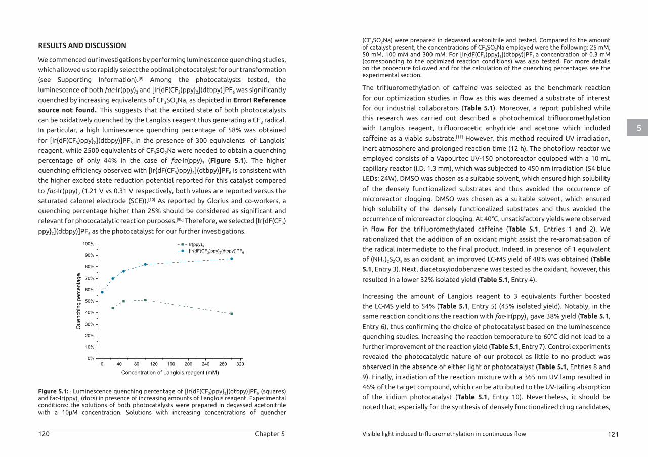
5
120 Chapter 5 Visible light induced trifluoromethylation in continuous flow 121
RESULTS AND DISCUSSION
We commenced our investigations by performing luminescence quenching studies,
which allowed us to rapidly select the optimal photocatalyst for our transformation
(see Supporting Information).[9] Among the photocatalysts tested, the
luminescence of both fac-Ir(ppy)3 and [Ir{dF(CF3)ppy}2](dtbpy)]PF6 was significantly
quenched by increasing equivalents of CF3SO2Na, as depicted in Error! Reference
source not found.. This suggests that the excited state of both photocatalysts
can be oxidatively quenched by the Langlois reagent thus generating a CF3 radical.
In particular, a high luminescence quenching percentage of 58% was obtained
for [Ir{dF(CF3)ppy}2](dtbpy)]PF6 in the presence of 300 equivalents of Langlois’
reagent, while 2500 equivalents of CF3SO2Na were needed to obtain a quenching
percentage of only 44% in the case of fac-Ir(ppy)3 (Figure 5.1). The higher
quenching efficiency observed with [Ir{dF(CF3)ppy}2](dtbpy)]PF6 is consistent with
the higher excited state reduction potential reported for this catalyst compared
to fac-Ir(ppy)3 (1.21 V vs 0.31 V respectively, both values are reported versus the
saturated calomel electrode (SCE)).[10] As reported by Glorius and co-workers, a
quenching percentage higher than 25% should be considered as significant and
relevant for photocatalytic reaction purposes.[9b] Therefore, we selected [Ir{dF(CF3)
ppy}2](dtbpy)]PF6 as the photocatalyst for our further investigations.
Figure 5.1: : Luminescence quenching percentage of [Ir{dF(CF3)ppy}2](dtbpy)]PF6 (squares) and fac-Ir(ppy)3 (dots) in presence of increasing amounts of Langlois reagent. Experimental conditions: the solutions of both photocatalysts were prepared in degassed acetonitrile with a 10μM concentration. Solutions with increasing concentrations of quencher
(CF3SO2Na) were prepared in degassed acetonitrile and tested. Compared to the amount of catalyst present, the concentrations of CF3SO2Na employed were the following: 25 mM, 50 mM, 100 mM and 300 mM. For [Ir{dF(CF3)ppy}2](dtbpy)]PF6 a concentration of 0.3 mM (corresponding to the optimized reaction conditions) was also tested. For more details on the procedure followed and for the calculation of the quenching percentages see the experimental section.
The trifluoromethylation of caffeine was selected as the benchmark reaction
for our optimization studies in flow as this was deemed a substrate of interest
for our industrial collaborators (Table 5.1). Moreover, a report published while
this research was carried out described a photochemical trifluoromethylation
with Langlois reagent, trifluoroacetic anhydride and acetone which included
caffeine as a viable substrate.[11] However, this method required UV irradiation,
inert atmosphere and prolonged reaction time (12 h). The photoflow reactor we
employed consists of a Vapourtec UV-150 photoreactor equipped with a 10 mL
capillary reactor (I.D. 1.3 mm), which was subjected to 450 nm irradiation (54 blue
LEDs; 24W). DMSO was chosen as a suitable solvent, which ensured high solubility
of the densely functionalized substrates and thus avoided the occurrence of
microreactor clogging. DMSO was chosen as a suitable solvent, which ensured
high solubility of the densely functionalized substrates and thus avoided the
occurrence of microreactor clogging. At 40°C, unsatisfactory yields were observed
in flow for the trifluoromethylated caffeine (Table 5.1, Entries 1 and 2). We
rationalized that the addition of an oxidant might assist the re-aromatisation of
the radical intermediate to the final product. Indeed, in presence of 1 equivalent
of (NH4)2S2O8 as an oxidant, an improved LC-MS yield of 48% was obtained (Table
5.1, Entry 3). Next, diacetoxyiodobenzene was tested as the oxidant, however, this
resulted in a lower 32% isolated yield (Table 5.1, Entry 4).
Increasing the amount of Langlois reagent to 3 equivalents further boosted
the LC-MS yield to 54% (Table 5.1, Entry 5) (45% isolated yield). Notably, in the
same reaction conditions the reaction with fac-Ir(ppy)3 gave 38% yield (Table 5.1,
Entry 6), thus confirming the choice of photocatalyst based on the luminescence
quenching studies. Increasing the reaction temperature to 60°C did not lead to a
further improvement of the reaction yield (Table 5.1, Entry 7). Control experiments
revealed the photocatalytic nature of our protocol as little to no product was
observed in the absence of either light or photocatalyst (Table 5.1, Entries 8 and
9). Finally, irradiation of the reaction mixture with a 365 nm UV lamp resulted in
46% of the target compound, which can be attributed to the UV-tailing absorption
of the iridium photocatalyst (Table 5.1, Entry 10). Nevertheless, it should be
noted that, especially for the synthesis of densely functionalized drug candidates,
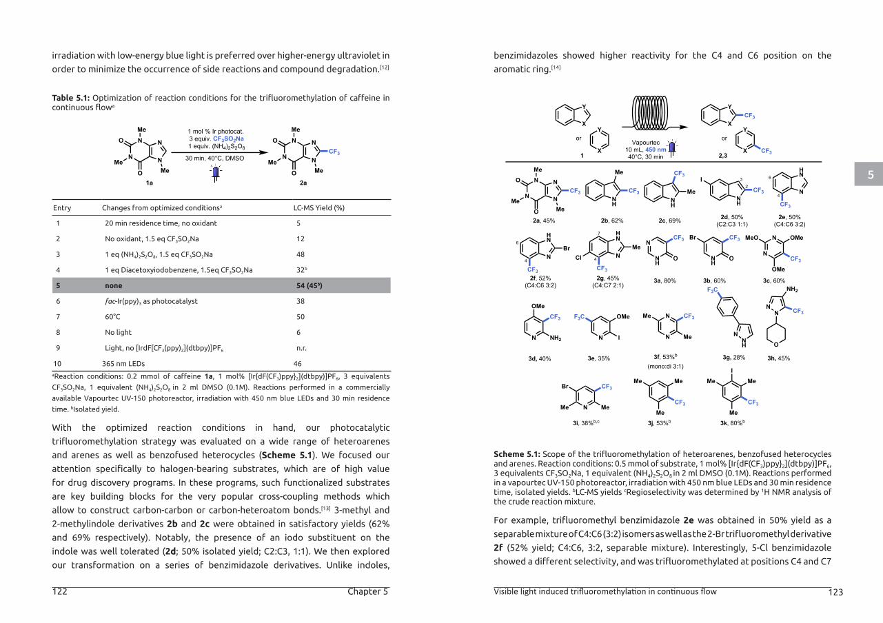
5
122 Chapter 5 Visible light induced trifluoromethylation in continuous flow 123
irradiation with low-energy blue light is preferred over higher-energy ultraviolet in
order to minimize the occurrence of side reactions and compound degradation.[12]
Table 5.1: Optimization of reaction conditions for the trifluoromethylation of caffeine in continuous flowa
Entry Changes from optimized conditionsa LC-MS Yield (%)
1 20 min residence time, no oxidant 5
2 No oxidant, 1.5 eq CF3SO2Na 12
3 1 eq (NH4)2S2O8, 1.5 eq CF3SO2Na 48
4 1 eq Diacetoxyiodobenzene, 1.5eq CF3SO2Na 32b
5 none 54 (45b)
6 fac-Ir(ppy)3 as photocatalyst 38
7 60°C 50
8 No light 6
9 Light, no [IrdF[CF3(ppy)2](dtbpy)]PF6 n.r.
10 365 nm LEDs 46aReaction conditions: 0.2 mmol of caffeine 1a, 1 mol% [Ir{dF(CF3)ppy}2](dtbpy)]PF6, 3 equivalents
CF3SO2Na, 1 equivalent (NH4)2S2O8 in 2 ml DMSO (0.1M). Reactions performed in a commercially
available Vapourtec UV-150 photoreactor, irradiation with 450 nm blue LEDs and 30 min residence
time. bIsolated yield.
With the optimized reaction conditions in hand, our photocatalytic
trifluoromethylation strategy was evaluated on a wide range of heteroarenes
and arenes as well as benzofused heterocycles (Scheme 5.1). We focused our
attention specifically to halogen-bearing substrates, which are of high value
for drug discovery programs. In these programs, such functionalized substrates
are key building blocks for the very popular cross-coupling methods which
allow to construct carbon-carbon or carbon-heteroatom bonds.[13] 3-methyl and
2-methylindole derivatives 2b and 2c were obtained in satisfactory yields (62%
and 69% respectively). Notably, the presence of an iodo substituent on the
indole was well tolerated (2d; 50% isolated yield; C2:C3, 1:1). We then explored
our transformation on a series of benzimidazole derivatives. Unlike indoles,
benzimidazoles showed higher reactivity for the C4 and C6 position on the
aromatic ring.[14]
Scheme 5.1: Scope of the trifluoromethylation of heteroarenes, benzofused heterocycles and arenes. Reaction conditions: 0.5 mmol of substrate, 1 mol% [Ir{dF(CF3)ppy}2](dtbpy)]PF6, 3 equivalents CF3SO2Na, 1 equivalent (NH4)2S2O8 in 2 ml DMSO (0.1M). Reactions performed in a vapourtec UV-150 photoreactor, irradiation with 450 nm blue LEDs and 30 min residence time, isolated yields. bLC-MS yields cRegioselectivity was determined by 1H NMR analysis of the crude reaction mixture.
For example, trifluoromethyl benzimidazole 2e was obtained in 50% yield as a
separable mixture of C4:C6 (3:2) isomers as well as the 2-Br trifluoromethyl derivative
2f (52% yield; C4:C6, 3:2, separable mixture). Interestingly, 5-Cl benzimidazole
showed a different selectivity, and was trifluoromethylated at positions C4 and C7
30 min, 40°C, DMSO
1 mol % Ir photocat.3 equiv. CF3SO2Na1 equiv. (NH4)2S2O8
O NMe
NMe
N
NMe
O
O NMe
NMe
N
NMe
O
CF3
1a 2a
Vapourtec10 mL, 450 nm40°C, 30 min
X
Y
or
X
Y
1
X
Y
or
X
Y
2,3
CF3
CF3
NH
CF3NH
Me N
HNMe CF3
N
N
N
NCF3
Me
Me
MeO
O
NH
I
N
HN
Br
CF32
3
CF3
4
CF3
4
6
N
HN
CF3
2a, 45% 2c, 69%2b, 62% 2d, 50%(C2:C3 1:1)
2e, 50%(C4:C6 3:2)
2f, 52%(C4:C6 3:2)
4
7
N
NH
N
N
CF3
OMeMeO
OMe
N NH2
OMe
O
CF3
NH
O
CF3Br
NNH
F3C
NN
NH2
CF3
ON I N
N
Me
CF3OMeF3C Me
3a, 80% 3b, 60% 3c, 60%
3d, 40% 3h, 45%3g, 28%3e, 35% 3f, 53%b
(mono:di 3:1)
2g, 45%(C4:C7 2:1)
CF3
MeMe
MeN
CF3Br
CF3
MeMe
Me
I
Me
3j, 53%b3i, 38%b,c 3k, 80%b
6
Cl
CF3
Me
Me
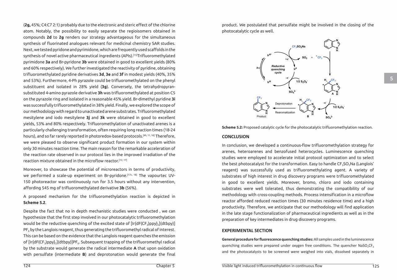
5
124 Chapter 5 Visible light induced trifluoromethylation in continuous flow 125
(2g, 45%; C4:C7 2:1) probably due to the electronic and steric effect of the chlorine
atom. Notably, the possibility to easily separate the regioisomers obtained in
compounds 2d to 2g renders our strategy advantageous for the simultaneous
synthesis of fluorinated analogues relevant for medicinal chemistry SAR studies.
Next, we tested pyridone and pyrimidone, which are frequently used scaffolds in the
synthesis of novel active pharmaceutical ingredients (APIs).[15]Trifluoromethylated
pyrimidone 3a and Br-pyridone 3b were obtained in good to excellent yields (80%
and 60% respectively). We further investigated the reactivity of pyridine, obtaining
trifluoromethylated pyridine derivatives 3d, 3e and 3f in modest yields (40%, 35%
and 53%). Furthermore, 4-Ph pyrazole could be trifluoromethylated on the phenyl
substituent and isolated in 28% yield (3g). Conversely, the tetrahydropyran-
substituted 4-amino pyrazole derivative 3h was trifluoromethylated at position C5
on the pyrazole ring and isolated in a reasonable 45% yield. Br-dimethyl pyridine 3i
was successfully trifluoromethylated in 38% yield. Finally, we explored the scope of
our methodology with regard to unactivated arene substrates. Trifluoromethylated
mesitylene and iodo mesitylene 3j and 3k were obtained in good to excellent
yields, 53% and 80% respectively. Trifluoromethylation of unactivated arenes is a
particularly challenging transformation, often requiring long reaction times (18-24
hours), and so far rarely reported in photoredox-based protocols.[4h, 11, 16] Therefore,
we were pleased to observe significant product formation in our system within
only 30 minutes reaction time. The main reason for the remarkable acceleration of
the reaction rate observed in our protocol lies in the improved irradiation of the
reaction mixture obtained in the microflow reactor.[12, 17]
Moreover, to showcase the potential of microreactors in terms of productivity,
we performed a scale-up experiment on Br-pyridone.[17c, 18] The vapourtec UV-
150 photoreactor was continuously run for 3.5 hours without any intervention,
affording 545 mg of trifluoromethylated derivative 3b (56%).
A proposed mechanism for the trifluoromethylation reaction is depicted in
Scheme 5.2.
Despite the fact that no in depth mechanistic studies were conducted , we can
hypothesize that the first step involved in our photocatalytic trifluoromethylation
would be the reductive quenching of the excited state of [Ir{dF(CF3)ppy}2](dtbpy)]
PF6 by the Langlois reagent, thus generating the trifluoromethyl radical of interest.
This can be based on the evidence that the Langlois reagent quenches the emission
of [Ir{dF(CF3)ppy}2](dtbpy)]PF6. Subsequent trapping of the trifluoromethyl radical
by the substrate would generate the radical intermediate A that upon oxidation
with persulfate (intermediate B) and deprotonation would generate the final
product. We postulated that persulfate might be involved in the closing of the
photocatalytic cycle as well.
Scheme 5.2: Proposed catalytic cycle for the photocatalytic trifluoromethylation reaction.
CONCLUSION
In conclusion, we developed a continuous-flow trifluoromethylation strategy for
arenes, heteroarenes and benzofused heterocycles. Luminescence quenching
studies were employed to accelerate initial protocol optimization and to select
the best photocatalyst for the transformation. Easy to handle CF3SO2Na (Langlois’
reagent) was successfully used as trifluoromethylating agent. A variety of
substrates of high interest in drug discovery programs were trifluoromethylated
in good to excellent yields. Moreover, bromo, chloro and iodo containing
substrates were well tolerated, thus demonstrating the compatibility of our
methodology with cross-coupling methods. Process intensification in a microflow
reactor afforded reduced reaction times (30 minutes residence time) and a high
productivity. Therefore, we anticipate that our methodology will find application
in the late stage functionalization of pharmaceutical ingredients as well as in the
preparation of key intermediates in drug discovery programs.
EXPERIMENTAL SECTION
General procedure for fluorescence quenching studies: All samples used in the luminescence quenching studies were prepared under oxygen free conditions. The quencher NaSO2CF3 and the photocatalysts to be screened were weighed into vials, dissolved separately in
IrIII*
Reductivequenching
cycleh
1/2 S2O8-
SO42-
CF3SO2Na
CF3+SO2
NH
NCF3H
NH
NCF3H
NH
N
NH
N
CF3-e-Deprotonation
Rearomatization
IrIII
IrII
Product
A
B
1/2 S2O8-
SO42-
+e-
-e-
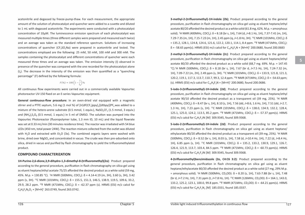
5
126 Chapter 5 Visible light induced trifluoromethylation in continuous flow 127
acetonitrile and degassed by freeze-pump-thaw. For each measurement, the appropriate amount of the solution of photocatalyst and quencher were added to a cuvette and diluted to 1 mL with degassed acetonitrile. The experiments were conducted with a photocatalyst concentration of 10μM. The luminescence emission spectrum of each photocatalyst was measured multiple times (three different samples were prepared and measured each twice) and an average was taken as the standard reference spectrum. Solutions of increasing concentrations of quencher (CF3SO2Na) were prepared in acetonitrile and tested. The concentrations employed are the following: 25 mM, 50 mM, 100 mM and 300 mM. The samples containing the photocatalyst and different concentrations of quencher were each measured three times and an average was taken. The emission intensity (I) observed in presence of the quencher was compared with the one recorded for the photocatalyst alone (I0). The decrease in the intensity of the emission was then quantified as a “quenching percentage” (F) defined by the following formula:
All continuous flow experiments were carried out in a commercially available Vapourtec photoreactor UV-150 fixed on an E-series Vapourtec equipment.
General continuous-flow procedure: In an oven-dried vial equipped with a magnetic stirrer and a PTFE septum, 5.6 mg (1 mol %) of [Ir{dF(CF3)ppy}2](dtbpy)]PF6 was added to a mixture of the hetero-arene substrate (0.5 mmol, 1 equiv.), NaSO2CF3 (1.5 mmol, 3 equiv.) and (NH4)2S2O8 (0.5 mmol, 1 equiv.) in 5 ml of DMSO. The solution was pumped into the Vapourtec Photoreactor (fluoropolymer tube, 1.3 mm ID, 10 mL) and the liquid flowrate was set at 0.33 mL/min (30 minutes residence time). The reactor was irradiated with 54 blue LEDs (450 nm, total power 24W). The reaction mixture collected from the outlet was diluted with H2O and extracted with Et2O (3x). The combined organic layers were washed with brine, dried over MgSO4 and concentrated in vacuo. The crude was then pre-adsorbed onto silica, dried in vacuo and purified by flash chromatography to yield the trifluoromethylated product.
COMPOUND CHARACTERIZATION
1H-Purine-2,6-dione,3,9-dihydro-1,3-dimethyl-8-(trifluoromethyl)(2a): Product prepared according to the general procedure, purification in flash chromatography on silica gel using as eluent heptane/ethyl acetate 75/25 afforded the desired product as a white solid (59 mg, 45%. M.p. = 130.85 °C). 1H NMR (500MHz, CDCl3): δ = 4.14-4.19 (m, 3H), 3.60 (s, 3H), 3.42 ppm (s, 3H). 13C NMR (101MHz, CDCl3): δ = 155.5, 151.3, 146.5, 138.9, 119.5, 109.6, 33.2, 29.9, 28.2 ppm. 19F NMR (471MHz, CDCl3): δ = -62.37 ppm (s). HRMS (ESI) m/z calcd for C9H9F3N4O2 + [M+H]+ 263.0749, found 263.0742.
3-methyl-2-(trifluoromethyl)-1H-indole (2b); Product prepared according to the general procedure, purification in flash chromatography on silica gel using as eluent heptane/ethyl acetate 80/20 afforded the desired product as a white solid (61.8 mg, 62%. M.p. = amorphous solid). 1H NMR (400MHz, CDCl3): δ = 8.18 (br s, 1H), 7.64 (d, J=8.1 Hz, 1H), 7.37-7.41 (m, 1H), 7.29-7.35 (m, 1H), 7.15-7.23 (m, 1H), 2.45 ppm (q, J=1.8 Hz, 3H). 13C NMR (101MHz, CDCl3): δ = 135.2, 128.1, 124.8, 124.6, 121.6, 122.2, 120.1, 114.1, 8.4 ppm. 19F NMR (471MHz, CDCl3): δ = -58.65 ppm(s). HRMS (ESI) m/z calcd for C10H8F3N + [M+H]+ 200.0680, found 200.0683
2-methyl-3-(trifluoromethyl)-1H-indole (2c): Product prepared according to the general procedure, purification in flash chromatography on silica gel using as eluent heptane/ethyl acetate 80/20 afforded the desired product as a white solid (68,7 mg. 69%. M.p. = 147.45 °C).1H NMR (500MHz, CDCl3): δ = 8.18 (br s, 1H), 7.67 (br d, J=7.5 Hz, 1H), 7.24-7.32 (m, 1H), 7.09-7.22 (m, 2H), 2.49 ppm (s, 3H). 13C NMR (101MHz, CDCl3): δ = 133.9, 121.8, 121.3, 120.2, 119.1, 117.3, 113.7, 110.7, 99.3, 12.4 ppm. 19F NMR (471MHz, CDCl3): δ = -54.63 ppm; (s). HRMS (ESI) m/z calcd for C10H8F3N + [M+H]+ 200.0680, found 200.0686.
5-iodo-3-(trifluoromethyl)-1H-indole (2d); Product prepared according to the general procedure, purification in flash chromatography on silica gel using as eluent heptane/ethyl acetate 90/10 afforded the desired product as a transparent oil (39 mg, 25%). 1H NMR (400MHz, CDCl3): δ = 8.47 (br s, 1H), 8.10 (s, 1H), 7.56 (dd, J=8.6, 1.6 Hz, 1H), 7.51 (dd, J=2.7, 1.3 Hz, 1H), 7.23 ppm (s, 1H). 13C NMR (101MHz, CDCl3): δ = 138.0, 134.9, 132.2, 128.4, 125.1, 125.0, 124.2, 113.5, 85.2 ppm. 19F NMR (471MHz, CDCl3): δ = -57.37 ppm(s). HRMS (ESI) m/z calcd for C9H5F3IN [M]- 309.9345, found 309.9368.
5-iodo-2-(trifluoromethyl)-1H-indole (2d): Product prepared according to the general procedure, purification in flash chromatography on silica gel using as eluent heptane/ethylacetate 80/20 afforded the desired product as a transparent oil (39 mg, 25%). 1H NMR (500MHz, CDCl3): δ = 8.52 (br s, 1H), 8.03 (s, 1H), 7.58 (d, J=10.4 Hz, 1H), 7.22 (d, J=8.4 Hz, 1H), 6.85 ppm (s, 1H). 13C NMR (101MHz, CDCl3): δ = 135.2, 133.2, 130.9, 129.1, 126.7, 126.4, 121.9, 113.7, 103.4, 84.5 ppm. 19F NMR (471MHz, CDCl3): δ = -60.73 ppm(s). HRMS (ESI) m/z calcd for C9H5F3IN [M]- 309.9345, found 309.9368.
4-(trifluoromethyl)benzimidazole (2e, C4:C6 3:2): Product prepared according to the general procedure, purification in flash chromatography on silica gel using as eluent heptane/ethylacetate 80/20 afforded the desired product as a white solid (27 mg, 29% M.p. = amorphous solid). 1H NMR (500MHz, CD3OD): δ = 8.20 (s, 1H), 7.63-7.88 (br s, 1H), 7.48 (br d, J=7.2 Hz, 1H), 7.31 ppm (t, J=7.8 Hz, 1H). 13C NMR (126MHz, CD3OD): δ = 164.1, 143.0, 133.2, 125.2, 123.1, 100.0, 99.8 ppm. 19F NMR (471MHz, CD3OD): δ = -64.21 ppm(s). HRMS (ESI) m/z calcd for C8H5F3N2 [M]- 185.0331, found 185.0337.
𝐹𝐹𝐹𝐹(%) = 100 �1 −II0�%
5
128 Chapter 5 Visible light induced trifluoromethylation in continuous flow 129
6-(trifluoromethyl)benzimidazole (2e C4:C6 3:2): Product prepared according to the general procedure, purification in flash chromatography on silica gel using as eluent heptane/ethylacetate 80/20 afforded the desired product as a yellow oil (19 mg, 20%). 1H NMR (400MHz, CDCl3): δ = 8.25 (s, 1H), 7.99 (s, 1H), 7.74 (d, J=8.6 Hz, 1H), 7.57 ppm (d, J=8.6 Hz, 1H). 13C NMR (101MHz, CDCl3): δ = 142.6, 128.7, 126.0, 125.7, 125.4, 123.3, 120.1 ppm. 19F NMR (471MHz, CDCl3): δ = -62.20 ppm(s). HRMS (ESI) m/z calcd for C8H5F3N2 [M]- 185.0331, found 185.0337.
2-bromo-4-(trifluoromethyl)benzimidazole (2f C4:C6 3:2): Product prepared according to the general procedure, purification in flash chromatography on silica gel using as eluent heptane/ethylacetate in gradient from 100/0 to 50/50 afforded the desired product as a white solid (40.2 mg, 30%. M.p. = 214.7 °C). 1H NMR (400MHz, CD3OD): δ = 7.85 (s, 1H), 7.68 (d, J=8.6 Hz, 1H), 7.55 ppm (d, J=8.6 Hz, 1H). 13C NMR (101MHz, CD3OD): δ = 140.8, 131.2, 130.1, 126.2, 122.2, 120.8, 115.7, 113.7 ppm. 19F NMR (471MHz, CD3OD): δ = -62.40 ppm (s). HRMS (ESI) m/z calcd for C8H4BrF3N2 [M]- 262.9436, found 262.9434.
2-bromo-6-(trifluoromethyl)benzimidazole (2f C4:C6 3:2): Product prepared according to the general procedure, purification in flash chromatography on silica gel using as eluent heptane/ethylacetate in gradient from 100/0 to 50/50 afforded the desired product as a white solid (26.7 mg, 20%. M.p. = 214.7 °C). 1H NMR (400MHz, CDCl3): δ = 8.25 (s, 1H), 7.99 (s, 1H), 7.74 (d, J=8.6 Hz, 1H), 7.57 ppm (d, J=8.6 Hz, 1H). 13C NMR (101MHz, CDCl3): δ = 142.6, 128.7, 126.0, 125.7, 125.4, 123.3, 120.1 ppm. 19F NMR (471MHz, CDCl3): δ = -62.20 ppm(s). HRMS (ESI) m/z calcd for C8H4BrF3N2 [M]- 262.9436, found 262.9434.
5-chloro-2-methyl-7-(trifluoromethyl)-1H-benzimidazol (2g C4:C7 2:1): Product prepared according to the general procedure, purification in flash chromatography on silica gel using as eluent heptane/ethylacetate 80/20 afforded the desired product as a white solid (23.8 mg, 20%.. M.p. = amorphous solid). 1H NMR (400MHz, CDCl3): δ = 9.48 (br s, 1H), 7.82 (br s, 1H), 7.47 (s, 1H), 2.68 ppm (s, 3H). 13C NMR (101MHz, CD3OD): δ = 157.3, 128.1, 126.1, 123.4, 120.7, 105.2, 14.3 ppm. 19F NMR (471MHz, CD3OD): δ = -62.87 ppm(s). HRMS (ESI) m/z calcd for C9H6ClF3N2 [M]- 233.0098, found 233.0108.
5-chloro-2-methyl-4-(trifluoromethyl)-1H-benzimidazol (2g C4:C7 2:1): Product prepared according to the general procedure, purification in flash chromatography on silica gel using as eluent heptane/ethylacetate 80/20 afforded the desired product as a white solid (35.2 mg, 30%. M.p. = amorphous solid). 1H NMR (500MHz, CDCl3): δ = 9.50 (br s, 1H), 7.74 (d, J=8.4 Hz, 1H), 7.34 (d, J=8.4 Hz, 1H), 2.66 ppm (s, 3H). 13C NMR (126MHz, CDCl3): δ = 153.3, 143.5, 131.9, 127.0, 125.1, 122.9, 15.3 ppm. 19F NMR (471MHz, CDCl3): δ = -57.09 ppm(s). HRMS (ESI) m/z calcd for C9H6ClF3N2 [M]- 233.0098, found 233.0108.
5-(trifluoromethyl)pyrimidin-4(3H)-on (3a): Product prepared according to the general procedure, the solvent was evaporated in Genevac turboevaporator in overnight, the rests of the reaction mixture were washed with dichloromethane and the solvent was evaporated, purification in flash chromatography on silica gel MeOH/NH4OH( 9:1)/Dichloromethane 0-10% the desired product as a yellow oil (65.9 mg, 80%). 1H NMR (400MHz, DMSO-d6): δ = 8.44 (s, 1H), 8.40 ppm (s, 1H). 13C NMR (126MHz, CDCl3): δ = 154.7, 152.1, 129.7, 121.9 ppm 19F NMR (471MHz, CDCl3): δ = -65.35 ppm(s). HRMS (ESI) m/z calcd for C5H3F3N2O [M]- 163.0124, found 163.0129.
5-bromo-3-(trifluoromethyl)-1H-pyridin-2-one (3b): Product prepared according the general procedure, purification in flash chromatography on silica gel using as eluent heptane/ethylacetate 50/50 afforded the desired product as a yellow solid (72.6 mg 60%. M.p. = 213.39ºC). 1H NMR (500MHz, CDCl3): δ = 12.52-14.24 (m, 1H), 7.92 (d, J=2.0 Hz, 1H), 7.76 ppm (d, J=2.3 Hz, 1H). 13C NMR (126MHz, CDCl3): δ = 160.0, 143.8, 139.4, 121.5, 121.9, 97.7 ppm. 19F NMR (471MHz, CDCl3): δ = -65.98 ppm. HRMS (ESI) m/z calcd for C6H3BrF3NO [M]- 239.9277, found 239.9272.
2,4,6-trimethoxy-5-(trifluoromethyl)pyrimidine (3c): Product prepared according to the general procedure, purification in flash chromatography on silica gel using as eluent heptane/ethylacetate 80/20 afforded the desired product as a pink solid (71.4 mg, 60%. M.p. = 123.6ºC). 1H NMR (500MHz, CDCl3): δ = 4.03 (s, 6H), 4.01 ppm (s, 3H). 13C NMR (101MHz, CDCl3): δ = 169.8, 165.0, 123.5, 89.3, 55.1, 55.0 ppm. 19F NMR (471MHz, CDCl3): δ = -55.97 ppm(s).
4-methoxy-3-(trifluoromethyl)pyridin-2-amine (3d): Product prepared according to the general procedure, purification in flash chromatography on silica gel using as eluent heptane/ethylacetate 40/60 afforded the desired product as a yellow solid (38.5 mg, 40%. M.p. = 213.4ºC). 1H NMR (400MHz, CDCl3): δ = 8.07 (d, J=5.8 Hz, 1H), 6.31 (dd, J=5.9, 0.8 Hz, 1H), 5.00-5.20 (m, 2H), 3.88 ppm (s, 3H). 13C NMR (101MHz, CDCl3): δ = 166.3, 156.6, 152.8, 124.9, 98.3, 56.1 ppm. 19F NMR (471MHz, CDCl3): δ = -55.42 ppm(s). HRMS (ESI) m/z calcd for C7H7F3N2O [M]- 191.0437, found 191.0423.
2-iodo-3-methoxy-5-(trifluoromethyl)pyridine (3e):Product prepared according the general procedure, purification in flash chromatography on silica gel using as eluent pentane/diethyl ether 90/10 afforded the desired product as a transparent oil (52.9 mg, 35%). 1H NMR (400MHz, CDCl3): δ = 7.59 (d, J=8.6 Hz, 1H), 7.05 (d, J=8.6 Hz, 1H), 3.98 ppm (s, 3H). 13C NMR (101MHz, CDCl3): δ = 157.4, 140.4, 134.2, 121.0, 116.1, 111.7, 56.7 ppm. 19F NMR (471MHz, CDCl3): δ = -66.70 ppm. HRMS (ESI) m/z calcd for C7H5F3INO [M+H]+ 303.9488, found 303.9492.
5
130 Chapter 5 Visible light induced trifluoromethylation in continuous flow 131
3-[4-(trifluoromethyl)phenyl]-1H-pyrazole (3g): Product prepared according to the general procedure, purification in flash chromatography on silica gel using as eluent heptane/ethylacetate 40/60 afforded the desired product as transparent oil (29.7 mg, 28%). 1H NMR (400MHz, CDCl3): δ = 7.90 (d, J=8.1 Hz, 2H), 7.65-7.70 (m, 1H), 7.62-7.74 (m, 2H), 6.70 ppm (d, J=2.3 Hz, 1H). 13C NMR (101MHz, CDCl3): δ = 136.0, 131.8, 129.5, 129.0, 128.8, 126.0, 125.7, 124.6, 122.6, 103.3 ppm. 19F NMR (471MHz, CDCl3): δ = -62.58 ppm(s). HRMS (ESI) m/z calcd for C10H7F3N2 [M]- 211.0488, found 211.0486.
1-tetrahydropyran-4-yl-5-(trifluoromethyl)pyrazol-4-amine (3h): Product prepared according to the general procedure, purification in flash chromatography on silica gel using as eluent heptane/ethylacetate 50/50 afforded the desired product as a dark yellow oil (52.9 mg, 45%). 1H NMR (400MHz, CDCl3): δ = 7.16 (s, 1H), 4.24 (tt, J=11.5, 4.0 Hz, 1H), 4.10 (dd, J=11.8, 4.6 Hz, 2H), 3.50 (td, J=12.2, 2.0 Hz, 2H), 3.28-3.42 (m, 2H), 2.26 (qd, J=12.4, 4.6 Hz, 2H), 1.78-1.92 ppm (m, 2H). 13C NMR (101MHz, CDCl3): δ = 130.8, 130.0, 121.8, 114.9, 67.1, 57.0, 32.9 ppm. 19F NMR (471MHz, CDCl3): δ = -56.70 ppm(s). HRMS (ESI) m/z calcd for C9H12F3N3O [M]- 234.2859, found 234.2855.
3-bromo-2,6-dimethyl-5-(trifluoromethyl)pyridine (3i); Product prepared according the general procedure. The organic layer was evaporated and the crude was analysed by LC-MS (38%). 1H NMR (400MHz, CDCl3): δ = 7.97 (s, 1H), 2.68 (s, 3H), 2.62-2.64 ppm (m, 3H). 19F NMR (471MHz, CDCl3): δ = -62.23 ppm.
1,3,5-trimethyl-2-(trifluoromethyl)benzene (3j); Product prepared according the general procedure. The organic layer was evaporated and the crude was analysed by LC-MS (53%).
2-iodo-1,3,5-trimethyl-4-(trifluoromethyl)benzene (3k); Product prepared according the general procedure. The organic layer was evaporated and the crude was analysed by LC-MS (80%).
ASSOCIATED CONTENT:
The Supporting Information for this article is available free of charge on the Thieme publication website at DOI: 10.1055/s-0036-1588527.
REFERENCES:[1] a) Y. Zhou, J. Wang, Z. Gu, S. Wang, W. Zhu, J. L. Aceña, V. A. Soloshonok, K. Izawa, H.
Liu, Chem. Rev. 2016, 116, 422-518; b) S. Purser, P. R. Moore, S. Swallow, V. Gouverneur, Chem. Soc. Rev. 2008, 37, 320-330; c) K. Müller, C. Faeh, F. Diederich, Science 2007, 317, 1881-1886.
[2] a) E. A. Ilardi, E. Vitaku, J. T. Njardarson, J. Med. Chem. 2014, 57, 2832-2842; b) Q. A. Huchet, B. Kuhn, B. Wagner, N. A. Kratochwil, H. Fischer, M. Kansy, D. Zimmerli, E. M. Carreira, K. Müller, J. Med. Chem. 2015, 58, 9041-9060.
[3] a) S. Barata-Vallejo, A. Postigo, Coord. Chem. Rev. 2013, 257, 3051-3069; b) O. A. Tomashenko, V. V. Grushin, Chem. Rev. 2011, 111, 4475-4521; c) M. Huiban, M. Tredwell, S. Mizuta, Z. Wan, X. Zhang, T. L. Collier, V. Gouverneur, J. Passchier, Nat. Chem. 2013, 5, 941-944.
[4] a) N. J. W. Straathof, S. E. Cramer, V. Hessel, T. Noël, Angew. Chem., Int. Ed. 2016, 55, 15549-15553; b) C. Bottecchia, X. J. Wei, K. P. Kuijpers, V. Hessel, T. Noel, J Org Chem 2016, 81, 7301-7307; c) Q. Lefebvre, N. Hoffmann, M. Rueping, Chem. Commun. 2016, 52, 2493-2496; d) T. Chatterjee, N. Iqbal, Y. You, E. J. Cho, Acc. Chem. Res. 2016, 49, 2284-2294; e) J. W. Beatty, J. J. Douglas, K. P. Cole, C. R. J. Stephenson, Nat. Commun. 2015, 6, 7919; f) N. J. W. Straathof, H. P. L. Gemoets, X. Wang, J. C. Schouten, V. Hessel, T. Noël, ChemSusChem 2014, 7, 1612-1617; g) C. K. Prier, D. A. Rankic, D. W. C. MacMillan, Chem. Rev. 2013, 113, 5322-5363; h) D. A. Nagib, D. W. C. MacMillan, Nature 2011, 480, 224-228; i) N. Iqbal, S. Choi, E. Kim, E. J. Cho, J. Org. Chem. 2012, 77, 11383-11387; j) L. Cui, Y. Matusaki, N. Tada, T. Miura, B. Uno, A. Itoh, Adv. Synth. Catal. 2013, 355, 2203-2207.
[5] a) X. Pan, H. Xia, J. Wu, Org. Chem. Front. 2016, 3, 1163-1185; b) S. Barata-Vallejo, B. Lantaño, A. Postigo, Chem. - Eur. J. 2014, 20, 16806-16829.
[6] a) Y. Ji, T. Brueckl, R. D. Baxter, Y. Fujiwara, I. B. Seiple, S. Su, D. G. Blackmond, P. S. Baran, PNAS 2011, 108, 14411-14415; b) D. Wang, G.-J. Deng, S. Chen, H. Gong, Green Chem. 2016, 18, 5967-5970; c) B. R. Langlois, T. Billard, J.-C. Mulatier, C. Yezeguelian, J. Fluorine Chem. 2007, 128, 851-856; d) B. R. Langlois, E. Laurent, N. Roidot, Tetrahedron Lett. 1991, 32, 7525-7528; e) M. Tordeux, B. Langlois, C. Wakselman, J. Org. Chem. 1989, 54, 2452-2453.
[7] a) Q. Lefebvre, Synlett 2016, 28, 19-23; b) C. Zhang, Adv. Synth. Catal. 2014, 356, 2895-2906.
[8] a) L. Huck, M. Berton, A. de la Hoz, A. Diaz-Ortiz, J. Alcazar, Green Chem. 2017, 19, 1420-1424; b) T. Wirth, ChemSusChem 2012, 5, 215-216; c) W. R. J. D. Galloway, A. Isidro-Llobet, D. R. Spring, Nat. Commun. 2010, 1, 1-13.
[9] a) M. Teders, A. Gómez-Suárez, L. Pitzer, M. N. Hopkinson, F. Glorius, Angew. Chem., Int. Ed. 2017, 56, 902-906; b) M. N. Hopkinson, A. Gómez-Suárez, M. Teders, B. Sahoo, F. Glorius, Angew. Chem., Int. Ed. 2016, 55, 4361-4366; c) T. B. Demissie, J. H. Hansen, Dalton Trans. 2016, 45, 10878-10882.
[10] K. Teegardin, J. I. Day, J. Chan, J. Weaver, Org. Process Res. Dev. 2016, 20, 1156-1163.
[11] L. Li, X. Mu, W. Liu, Y. Wang, Z. Mi, C.-J. Li, J. Am. Chem. Soc. 2016, 138, 5809-5812.
[12] D. Cambié, C. Bottecchia, N. J. W. Straathof, V. Hessel, T. Noël, Chem. Rev. 2016, 116, 10276-10341.
132 Chapter 5
[13] a) D. G. Brown, J. Boström, J. Med. Chem. 2016, 59, 4443-4458; b) N. Alonso, L. Z. Miller, J. de M. Muñoz, J. Alcázar, D. T. McQuade, Adv. Synth. Catal. 2014, 356, 3737-3741; c) B. Egle, J. Muñoz, N. Alonso, W. De Borggraeve, A. de la Hoz, A. Díaz-Ortiz, J. Alcázar, J. Flow Chem. 2014, 4, 22-25; d) J. de M. Muñoz, J. Alcázar, A. de la Hoz, A. Díaz-Ortiz, Adv. Synth. Catal. 2012, 354, 3456-3460; e) T. Noël, A. J. Musacchio, Org. Lett. 2011, 13, 5180-5183; f) T. W. J. Cooper, I. B. Campbell, S. J. F. Macdonald, Angew. Chem., Int. Ed. 2010, 49, 8082-8091.
[14] G.-L. Gao, C. Yang, W. Xia, Chem. Commun. 2017, 53, 1041-1044.
[15] a) X. Linghu, N. Wong, H. Iding, V. Jost, H. Zhang, S. G. Koenig, C. G. Sowell, F. Gosselin, Org. Process Res. Dev. 2017, 21, 387-398; b) A. Peng, J. Jiang, P. Hu, Y. Luo, Journal of Chromatography B 2010, 878, 2442-2448.
[16] B. Chang, H. Shao, P. Yan, W. Qiu, Z. Weng, R. Yuan, ACS Sustainable Chem. Eng. 2017, 5, 334-341.
[17] a) T. Noёl, Photochemical Processes in Continuous-Flow Reactors, World Scientific, New Jersey, 2017; b) J. W. Tucker, Y. Zhang, T. F. Jamison, C. R. J. Stephenson, Angew. Chem., Int. Ed. 2012, 51, 4144-4147; c) L. D. Elliott, J. P. Knowles, P. J. Koovits, K. G. Maskill, M. J. Ralph, G. Lejeune, L. J. Edwards, R. I. Robinson, I. R. Clemens, B. Cox, D. D. Pascoe, G. Koch, M. Eberle, M. B. Berry, K. I. Booker-Milburn, Chem. - Eur. J. 2014, 20, 15226-15232; d) J. P. Knowles, L. D. Elliott, K. I. Booker-Milburn, Beilstein J. Org. Chem. 2012, 8, 2025-2052.
[18] a) L. D. Elliott, M. Berry, B. Harji, D. Klauber, J. Leonard, K. I. Booker-Milburn, Org. Process Res. Dev. 2016, 20, 1806-1811; b) I. Abdiaj, J. Alcázar, Bioorg. Med. Chem. 2016, DOI: 10.1016/j.bmc.2016.12.041; c) Y. Su, K. Kuijpers, V. Hessel, T. Noël, React. Chem. Eng. 2016, 1, 73-81.
CHAPTER 6
De novo design of organic photocatalysts: bithiophene derivatives for the visible-light induced C-H functionalization of heteroarenes
This chapter is based on:
Bottecchia, C.; Martin, R.; Abdiaj, I.; Crovini, E.; Alcazar, J.; Orduna, J.; Blesa, M. J.; Muñoz, Carillo J.R.; Prieto, P.; Noël, T., Adv. Synth. Catal. 2018, DOI: 10.1002/adsc.201801571
6
136 Chapter 6 De novo design of organic photocatalysts 137
ABSTRACT
In this chapter, the de novo synthesis and characterization of a series of substituted
bis-thiophene derivatives as novel and inexpensive organic photocatalysts
is described. DFT calculations were used to predict a priori their absorption
spectra and redox potentials, which were then confirmed with empirical data.
The photocatalytic activity of this novel class of organic photoredox catalyst was
demonstrated in two visible-light mediated strategies for the C-H functionalization
of heteroarenes. The implementation of these strategies in a continuous-flow
photo-microreactor afforded moderate to excellent yields within few minutes
of reaction time. Due to their straightforward synthesis, low cost and good
photocatalytic properties, the proposed bis-thiophene derivatives could represent
a novel class of organic photoredox catalysts.
Visible-light photoredox catalysis received increasing attention in the last decade as
a powerful strategy enabling novel transformations under mild reaction conditions
(i.e. room temperature, atmospheric pressure and visible-light irradiation).[1] In
photoredox catalysis, the ability of a photocatalyst to absorb light in the visible
light range, reach an excited state and then undergo either energy or electron
transfers with the substrates of interest is paramount.[2] Generally speaking, Ir and
Ru polypyridyl complexes are among the most employed photocatalyst, offering
excellent redox potentials in their excited states and long-lived exciton lifetimes.[3] However, the main drawbacks associated with their use are their prohibitive
costs and scarce availability.[4] More recently, a number of studies demonstrated
that organic photocatalysts often provide valuable and inexpensive alternatives to
transition metals.[4-5] Nevertheless, the choice of a suitable organic photocatalyst
might be limited for reactions proceeding in acidic medium (e.g. Eosin Y is pH
sensitive) or in reducing environments promoting photobleaching.[6]
In this light, the development of novel classes of organic photoredox catalysts with
good redox properties, and largely available or easily prepared in high yields would
contribute to further advance research in photoredox catalysis.[7] Due to their
functional properties and versatility, deriving from the ease of functionalization of
the ring as well as the lengthening of the chain, thiophene based materials are of
broad interest across multiple disciplines. For example, in organic electronics their
semiconductor properties are exploited in organic field-effect transistors (OFETs)
and in photovoltaic devices.[8]
However, examples showing their use in the field of photoredox catalysis remain
scarce.[9] Thus, we became interested in probing the photocatalytic properties
of a series of 2,2’-bithiophene-based derivatives decorated with different
electron donating and electron withdrawing groups. In order to rapidly evaluate
the suitability of said structures as photoredox catalysts, we reasoned that
computational studies might represent a useful tool to predict their properties
a priori. Specifically, through TD-DFT[10] calculations (M06-2X[11], using CPCM[12],
CHCl3, see experimental section for further details), the absorption maximum and
emission maximum of this class of compounds were calculated, together with their
redox potentials. Based on this theoretical information, and taking into account
the commercial availability of the required starting materials, we selected a cluster
of six molecules to be synthesized (Scheme 6.1). Photocatalysts A to F were all
obtained in good to excellent yields through a one-step double Sonogashira cross-
coupling, starting from inexpensive and readily available alkynyl precursors (see
general procedure 1 in the experimental section).[13] The optimized procedure

6
138 Chapter 6 De novo design of organic photocatalysts 139
was performed with minimal amount of solvent, under microwave irradiation and
employing recycled Pd catalyst.
Gratifyingly, the calculated theoretical values for the maximum absorption were
found to be in good agreement with the experimental measurements (Scheme 6.1
and experimental section). The UV-Visible spectra of all of the studied compounds
showed a unique absorption band in the 400 nm region with significant tailing
towards the blue light region, thus supporting our initial hypothesis that these
compounds might be useful in visible-light driven catalytic reactions.
Scheme 6.1: Overview of the six 2,2’-bisthiophene-based photocatalyst synthesized and comparison of their calculated vs experimental properties. All potential values are reported vs SCE (saturated calomel electrode). Calculated values for Absmax, Emmax and redox potentials for the proposed compounds were obtained through DFT calculations in chloroform solution using the conductor-like polarizable continuum model (CPCM)[1] at CPCM-M06-2X/6-311+G(2d,p)//CPCM-M06-2X/6-31G* in chloroform. These values were obtained by our collaborators in UCLM. For more details see experimental section. The excited state potentials were estimated
The redox properties of the reported bithiophenes were followed by Cyclic
Voltammetry (CV) and Differential Pulse Voltammetry (DPV) in CHCl3, and matched
closely the calculated theoretical values (Scheme 6.1). As expected, compounds
A, B and C, bearing electron-donating groups, showed lower oxidation potential
than compounds D and E, bearing electron-withdrawing groups. Moreover, a good
correlation between the experimental oxidation potentials and the Hammett
constant values for the substituents on the arene ring was found (see Figure 6.9
experimental section).
Notably, such correlation hints at the possibility to carefully design other members
of this photocatalytic series with increasing redox potential by further modulating
the nature and position of the substituents on the aryl ring. For all members of
the series, the theoretical reduction potentials were calculated to be higher than
-2V, and thus could not be confirmed experimentally due to the limited potential
window of CHCl3.[14] By combining the information derived from the absorption
spectra and the oxidation/reduction potentials, an approximation of the excited
state potentials for compounds A to F was made (Scheme 6.1), which appeared
in good agreement with the theoretical calculations. Notably, all compounds
of the series showed excited state potentials comparable to commonly used
photocatalysts (see also Table 6.3 in the experimental section).[3-4]
To test the activity of the bi-thiophene derivatives as photoredox catalysts, we
commenced our investigations by employing them in the C-H functionalization of
heteroarenes with malonate derivatives.[15] The same transformation was previously
reported to proceed with either Ru(bpy)32+ or with an organic photocatalyst, and
was therefore selected as benchmark reaction.[9, 15] As depicted in Table 6.1, we
initially tested the ability of our photocatalysts to catalyse the reaction between
3-Me indole (1a) and Br-malonate in presence of triphenylamine as sacrificial
electron donor. Subjected to blue LED irradiation, 87% of the desired alkylated
indole (2a) was obtained within 5 hours with 1 mol% of photocatalyst D (Table 6.1,
entry 1). Gratifyingly, our photocatalyst outperformed Ru(bpy)32+(Table 6.1 entry
3), and compared positively with the benzothiadiazole-based organic photocatalyst
Th-BT-Th (Table 6.1, entry 2, reference [9]). In order to better match the irradiation
wavelength with the photocatalyst maximum absorption, we then conducted the
reaction under irradiation with 400 nm LEDs, obtaining 75% of product within only
30 minutes. (Table 6.1, entry 4). Higher concentrations of photocatalyst did not
result in increased amounts of product (Table 6.1 entry 5 and 6).
S
S
R
R
A:
OMeMeO
MeO
2,2'-bithiophene-basedorganic photocatalysts
F:D: E:
NC
C:
MeO
B:
OMe
MeO
S
CF3
Calc. Absmax
Exp. Absmax
C
401 nm
393 nm
A B E FD
Calc. E1/2ox
Exp. E1/2ox 1.08 V
1.25 V
399 nm
388 nm
1.22 V
1.26 V
407 nm
390 nm
1.02 V
1.03 V
401 nm
390 nm
1.34 V
1.28 V
410 nm
398 nm
1.34 V
1.51 V
417 nm
400 nm
1.33 V
1.26 V
Calc. E1/2red -2.22 V -2.18 V -2.24 V -2.0 V -1.90 V -2.05 V
E*1/2 red=PC*/PC 0.57 V 0.68 V 0.74 V 0.78 V 0.58 V
-1.49 V -1.38 V -1.46 V -1.17 V -1.37 VE*1/2 ox=PC /PC* -1.49 V
0.53 V
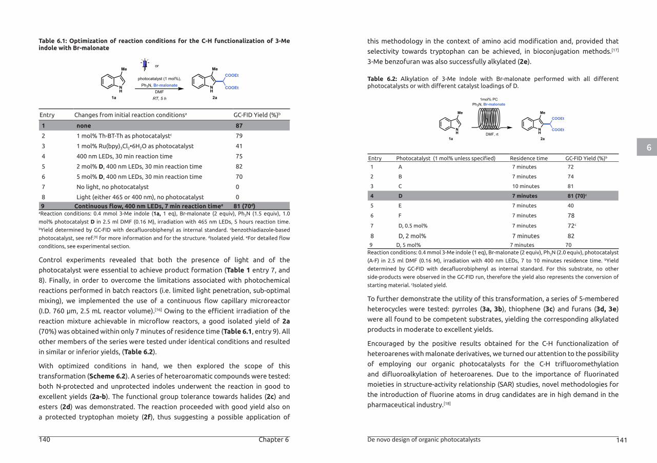
6
140 Chapter 6 De novo design of organic photocatalysts 141
Table 6.1: Optimization of reaction conditions for the C-H functionalization of 3-Me indole with Br-malonate
Entry Changes from initial reaction conditionsa GC-FID Yield (%)b
1 none 87
2 1 mol% Th-BT-Th as photocatalystc 79
3 1 mol% Ru(bpy)3Cl2•6H2O as photocatalyst 41
4 400 nm LEDs, 30 min reaction time 75
5 2 mol% D, 400 nm LEDs, 30 min reaction time 82
6 5 mol% D, 400 nm LEDs, 30 min reaction time 70
7 No light, no photocatalyst 0
8 Light (either 465 or 400 nm), no photocatalyst 0
9 Continuous flow, 400 nm LEDs, 7 min reaction timee 81 (70d)aReaction conditions: 0.4 mmol 3-Me indole (1a, 1 eq), Br-malonate (2 equiv), Ph3N (1.5 equiv), 1.0
mol% photocatalyst D in 2.5 ml DMF (0.16 M), irradiation with 465 nm LEDs, 5 hours reaction time. bYield determined by GC-FID with decafluorobiphenyl as internal standard. cbenzothiadiazole-based
photocatalyst, see ref.[9] for more information and for the structure. dIsolated yield. eFor detailed flow
conditions, see experimental section.
Control experiments revealed that both the presence of light and of the
photocatalyst were essential to achieve product formation (Table 1 entry 7, and
8). Finally, in order to overcome the limitations associated with photochemical
reactions performed in batch reactors (i.e. limited light penetration, sub-optimal
mixing), we implemented the use of a continuous flow capillary microreactor
(I.D. 760 μm, 2.5 mL reactor volume).[16] Owing to the efficient irradiation of the
reaction mixture achievable in microflow reactors, a good isolated yield of 2a
(70%) was obtained within only 7 minutes of residence time (Table 6.1, entry 9). All
other members of the series were tested under identical conditions and resulted
in similar or inferior yields, (Table 6.2).
With optimized conditions in hand, we then explored the scope of this
transformation (Scheme 6.2). A series of heteroaromatic compounds were tested:
both N-protected and unprotected indoles underwent the reaction in good to
excellent yields (2a-b). The functional group tolerance towards halides (2c) and
esters (2d) was demonstrated. The reaction proceeded with good yield also on
a protected tryptophan moiety (2f), thus suggesting a possible application of
this methodology in the context of amino acid modification and, provided that
selectivity towards tryptophan can be achieved, in bioconjugation methods.[17]
3-Me benzofuran was also successfully alkylated (2e).
Table 6.2: Alkylation of 3-Me Indole with Br-malonate performed with all different photocatalysts or with different catalyst loadings of D.
Entry Photocatalyst (1 mol% unless specified) Residence time GC-FID Yield (%)b
1 A 7 minutes 72
2 B 7 minutes 74
3 C 10 minutes 81
4 D 7 minutes 81 (70)c
5 E 7 minutes 40
6 F 7 minutes 78
7 D, 0.5 mol% 7 minutes 72c
8 D, 2 mol% 7 minutes 82 9 D, 5 mol% 7 minutes 70Reaction conditions: 0.4 mmol 3-Me indole (1 eq), Br-malonate (2 equiv), Ph3N (2.0 equiv), photocatalyst
(A-F) in 2.5 ml DMF (0.16 M), irradiation with 400 nm LEDs, 7 to 10 minutes residence time. bYield
determined by GC-FID with decafluorobiphenyl as internal standard. For this substrate, no other
side-products were observed in the GC-FID run, therefore the yield also represents the conversion of
starting material. cIsolated yield.
To further demonstrate the utility of this transformation, a series of 5-membered
heterocycles were tested: pyrroles (3a, 3b), thiophene (3c) and furans (3d, 3e)
were all found to be competent substrates, yielding the corresponding alkylated
products in moderate to excellent yields.
Encouraged by the positive results obtained for the C-H functionalization of
heteroarenes with malonate derivatives, we turned our attention to the possibility
of employing our organic photocatalysts for the C-H trifluoromethylation
and difluoroalkylation of heteroarenes. Due to the importance of fluorinated
moieties in structure-activity relationship (SAR) studies, novel methodologies for
the introduction of fluorine atoms in drug candidates are in high demand in the
pharmaceutical industry.[18]
1a 2a
photocatalyst (1 mol%),Ph3N, Br-malonate
DMFRT, 5 h
NH
Me
NH
MeCOOEt
COOEt
or
1a 2a
NH
Me
NH
MeCOOEt
COOEtDMF, rt
1mol% PCPh3N, Br-malonate
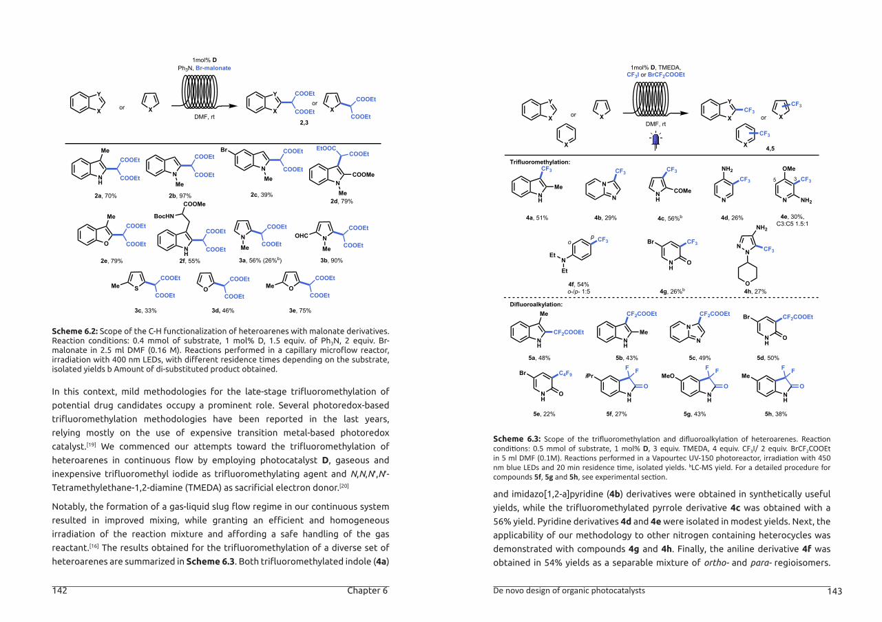
6
142 Chapter 6 De novo design of organic photocatalysts 143
Scheme 6.2: Scope of the C-H functionalization of heteroarenes with malonate derivatives. Reaction conditions: 0.4 mmol of substrate, 1 mol% D, 1.5 equiv. of Ph3N, 2 equiv. Br-malonate in 2.5 ml DMF (0.16 M). Reactions performed in a capillary microflow reactor, irradiation with 400 nm LEDs, with different residence times depending on the substrate, isolated yields b Amount of di-substituted product obtained.
In this context, mild methodologies for the late-stage trifluoromethylation of
potential drug candidates occupy a prominent role. Several photoredox-based
trifluoromethylation methodologies have been reported in the last years,
relying mostly on the use of expensive transition metal-based photoredox
catalyst.[19] We commenced our attempts toward the trifluoromethylation of
heteroarenes in continuous flow by employing photocatalyst D, gaseous and
inexpensive trifluoromethyl iodide as trifluoromethylating agent and N,N,N′,N′-Tetramethylethane-1,2-diamine (TMEDA) as sacrificial electron donor.[20]
Notably, the formation of a gas-liquid slug flow regime in our continuous system
resulted in improved mixing, while granting an efficient and homogeneous
irradiation of the reaction mixture and affording a safe handling of the gas
reactant.[16] The results obtained for the trifluoromethylation of a diverse set of
heteroarenes are summarized in Scheme 6.3. Both trifluoromethylated indole (4a)
Scheme 6.3: Scope of the trifluoromethylation and difluoroalkylation of heteroarenes. Reaction conditions: 0.5 mmol of substrate, 1 mol% D, 3 equiv. TMEDA, 4 equiv. CF3I/ 2 equiv. BrCF2COOEt in 5 ml DMF (0.1M). Reactions performed in a Vapourtec UV-150 photoreactor, irradiation with 450 nm blue LEDs and 20 min residence time, isolated yields. bLC-MS yield. For a detailed procedure for compounds 5f, 5g and 5h, see experimental section.
and imidazo[1,2-a]pyridine (4b) derivatives were obtained in synthetically useful
yields, while the trifluoromethylated pyrrole derivative 4c was obtained with a
56% yield. Pyridine derivatives 4d and 4e were isolated in modest yields. Next, the
applicability of our methodology to other nitrogen containing heterocycles was
demonstrated with compounds 4g and 4h. Finally, the aniline derivative 4f was
obtained in 54% yields as a separable mixture of ortho- and para- regioisomers.
DMF, rtX
Y
or
2,3
1mol% DPh3N, Br-malonate
X X
Yor
X
NH
Me
2a, 70% 2b, 97% 2c, 39%2d, 79%
2e, 79% 3a, 56% (26%b) 3b, 90%
3d, 46%3c, 33%
COOEt
COOEt
N COOEt
COOEt
Me
N COOEt
COOEt
Me
Br
NMe
COOMe
EtOOCCOOEt
O
Me
COOEt
COOEt
2f, 55%
NH
COOEt
COOEt
COOMe
BocHN
NCOOEt
COOEtMeN
COOEt
COOEtMe
OHC
OCOOEt
COOEtS
COOEt
COOEtMe
3e, 75%
OCOOEt
COOEtMe
COOEt
COOEt
COOEt
COOEt
DMF, rtX
Y
or
4,5
NH
CF3
4a, 51% 4c, 56%b4b, 29%
4f, 54%o-/p- 1:5
4d, 26% 4e, 30%,C3:C5 1.5:1
1mol% D, TMEDA,CF3I or BrCF2COOEt
X
X
Me N
N
CF3
NH
CF3
COMe
NEt
Et
CF3po
N
CF3
NH2
N
CF3
OMe
NH2
35
4g, 26%b
NH
CF3
O
Br
4h, 27%
NN
NH2
CF3
O
Trifluoromethylation:
Difluoroalkylation:
NH
5a, 48% 5c, 49%
CF2COOEtN
N
CF2COOEt
5e, 22%
NH
C4F9
O
Br
Me
5d, 50%
NH
CF2COOEt
O
Br
NH
F F
OiPr
5f, 27%
NH
F F
OMeO
5g, 43%
NH
F F
OMe
5h, 38%
NH
5b, 43%
CF2COOEt
Me
X
Y
or X
X
CF3CF3
CF3
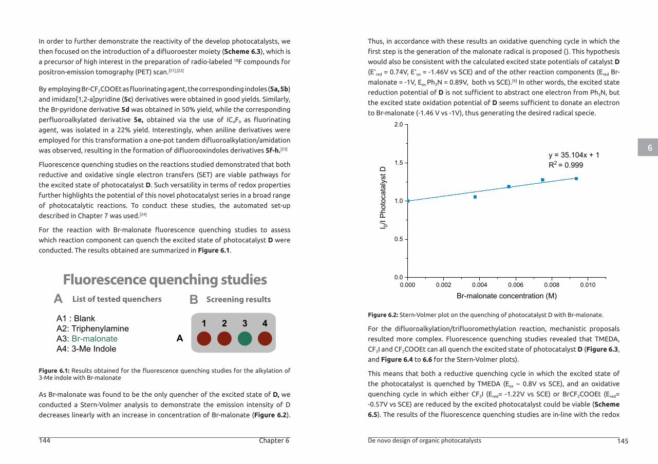
6
144 Chapter 6 De novo design of organic photocatalysts 145
In order to further demonstrate the reactivity of the develop photocatalysts, we
then focused on the introduction of a difluoroester moiety (Scheme 6.3), which is
a precursor of high interest in the preparation of radio-labeled 18F compounds for
positron-emission tomography (PET) scan.[21],[22]
By employing Br-CF2COOEt as fluorinating agent, the corresponding indoles (5a, 5b)
and imidazo[1,2-a]pyridine (5c) derivatives were obtained in good yields. Similarly,
the Br-pyridone derivative 5d was obtained in 50% yield, while the corresponding
perfluoroalkylated derivative 5e, obtained via the use of IC4F9 as fluorinating
agent, was isolated in a 22% yield. Interestingly, when aniline derivatives were
employed for this transformation a one-pot tandem difluoroalkylation/amidation
was observed, resulting in the formation of difluorooxindoles derivatives 5f-h.[23]
Fluorescence quenching studies on the reactions studied demonstrated that both
reductive and oxidative single electron transfers (SET) are viable pathways for
the excited state of photocatalyst D. Such versatility in terms of redox properties
further highlights the potential of this novel photocatalyst series in a broad range
of photocatalytic reactions. To conduct these studies, the automated set-up
described in Chapter 7 was used.[24]
For the reaction with Br-malonate fluorescence quenching studies to assess
which reaction component can quench the excited state of photocatalyst D were
conducted. The results obtained are summarized in Figure 6.1.
Figure 6.1: Results obtained for the fluorescence quenching studies for the alkylation of 3-Me indole with Br-malonate
As Br-malonate was found to be the only quencher of the excited state of D, we
conducted a Stern-Volmer analysis to demonstrate the emission intensity of D
decreases linearly with an increase in concentration of Br-malonate (Figure 6.2).
Thus, in accordance with these results an oxidative quenching cycle in which the
first step is the generation of the malonate radical is proposed (). This hypothesis
would also be consistent with the calculated excited state potentials of catalyst D
(E*red = 0.74V, E*
ox = -1.46V vs SCE) and of the other reaction components (Ered Br-
malonate = -1V, Eox Ph3N = 0.89V, both vs SCE).[9] In other words, the excited state
reduction potential of D is not sufficient to abstract one electron from Ph3N, but
the excited state oxidation potential of D seems sufficient to donate an electron
to Br-malonate (-1.46 V vs -1V), thus generating the desired radical specie.
Figure 6.2: Stern-Volmer plot on the quenching of photocatalyst D with Br-malonate.
For the difluoroalkylation/trifluoromethylation reaction, mechanistic proposals
resulted more complex. Fluorescence quenching studies revealed that TMEDA,
CF3I and CF2COOEt can all quench the excited state of photocatalyst D (Figure 6.3,
and Figure 6.4 to 6.6 for the Stern-Volmer plots).
This means that both a reductive quenching cycle in which the excited state of
the photocatalyst is quenched by TMEDA (Eox ~ 0.8V vs SCE), and an oxidative
quenching cycle in which either CF3I (Ered= -1.22V vs SCE) or BrCF2COOEt (Ered=
-0.57V vs SCE) are reduced by the excited photocatalyst could be viable (Scheme
6.5). The results of the fluorescence quenching studies are in-line with the redox
A1 2 3 4
A BFluorescence quenching studies
Screening resultsList of tested quenchers
A1 : BlankA2: TriphenylamineA3: Br-malonateA4: 3-Me Indole
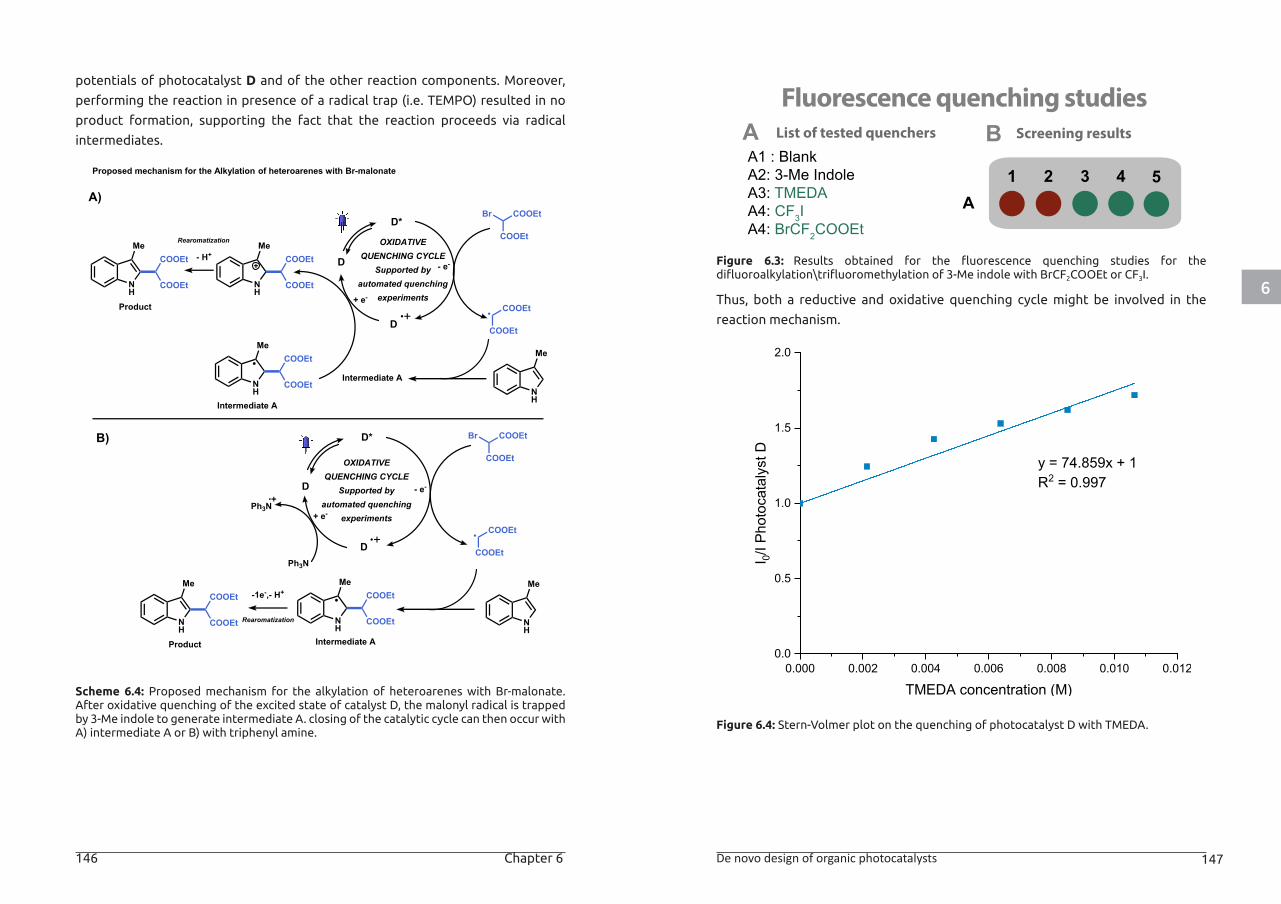
6
146 Chapter 6 De novo design of organic photocatalysts 147
potentials of photocatalyst D and of the other reaction components. Moreover,
performing the reaction in presence of a radical trap (i.e. TEMPO) resulted in no
product formation, supporting the fact that the reaction proceeds via radical
intermediates.
Scheme 6.4: Proposed mechanism for the alkylation of heteroarenes with Br-malonate. After oxidative quenching of the excited state of catalyst D, the malonyl radical is trapped by 3-Me indole to generate intermediate A. closing of the catalytic cycle can then occur with A) intermediate A or B) with triphenyl amine.
Figure 6.3: Results obtained for the fluorescence quenching studies for the difluoroalkylation\trifluoromethylation of 3-Me indole with BrCF2COOEt or CF3I.
Thus, both a reductive and oxidative quenching cycle might be involved in the
reaction mechanism.
Figure 6.4: Stern-Volmer plot on the quenching of photocatalyst D with TMEDA.
D
D*
OXIDATIVEQUENCHING CYCLE
Supported byautomated quenching
experiments
- e-
Proposed mechanism for the Alkylation of heteroarenes with Br-malonate
Intermediate A
Intermediate A
COOEtBr
COOEt
COOEt
COOEt
NH
Me
NH
MeCOOEt
COOEt
NH
MeCOOEt
COOEt
Product
NH
MeCOOEt
COOEt
D
OXIDATIVEQUENCHING CYCLE
Supported byautomated quenching
experiments
-1e-,- H+
Rearomatization
Intermediate A
COOEtBr
COOEt
COOEt
COOEt
NH
Me
NH
MeCOOEt
COOEtNH
MeCOOEt
COOEt
Product
Ph3N
Ph3N
A)
B)
D
D
+ e-
+ e-
- e-
D*
- H+Rearomatization
A1 2 3 4
A BFluorescence quenching studies
Screening resultsList of tested quenchers
A1 : BlankA2: 3-Me IndoleA3: TMEDAA4: CF3IA4: BrCF2COOEt
5
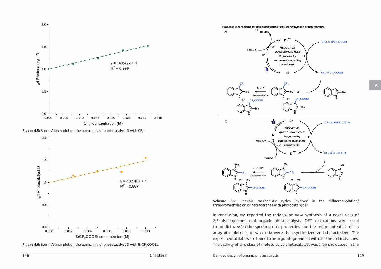
6
148 Chapter 6 De novo design of organic photocatalysts 149
Figure 6.5: Stern-Volmer plot on the quenching of photocatalyst D with CF3I.
Figure 6.6: Stern-Volmer plot on the quenching of photocatalyst D with BrCF2COOEt.
Scheme 6.5: Possible mechanistic cycles involved in the difluoroalkylation/trifluoromethylation of heteroarenes with photocatalyst D.
In conclusion, we reported the rational de novo synthesis of a novel class of
2,2’-bisthiophene-based organic photocatalysts. DFT calculations were used
to predict a priori the spectroscopic properties and the redox potentials of an
array of molecules, of which six were then synthesized and characterized. The
experimental data were found to be in good agreement with the theoretical values.
The activity of this class of molecules as photocatalyst was then showcased in the
D*
REDUCTIVEQUENCHING CYCLE
Supported byautomated quenching
experiments
+ e-
-1e-,- H+
Rearomatization NH
NH
CF3
or
CF3I or BrCF2COOEt
CF3 or CF2COOEt
Proposed mechanisms for difluoroalkylation/ trifluoromethylation of heteroarenes
TMEDA
TMEDA
D
D
or
MeMe
NH
CF2COOEt
Me
NH
CF2COOEt
Me
NH
CF3
Me
OXIDATIVEQUENCHING CYCLE
Supported byautomated quenching
experiments
- e-
-1e-,- H+
Rearomatization NH
Me
NH
Me
NH
Me
CF3
TMEDA
TMEDA
B)
D
CF3I or BrCF2COOEt
CF3 or CF2COOEt
CF3
+ e-
- e-
A)
NH
Me
NH
Me
CF2COOEt CF2COOEt
or or
D*
D
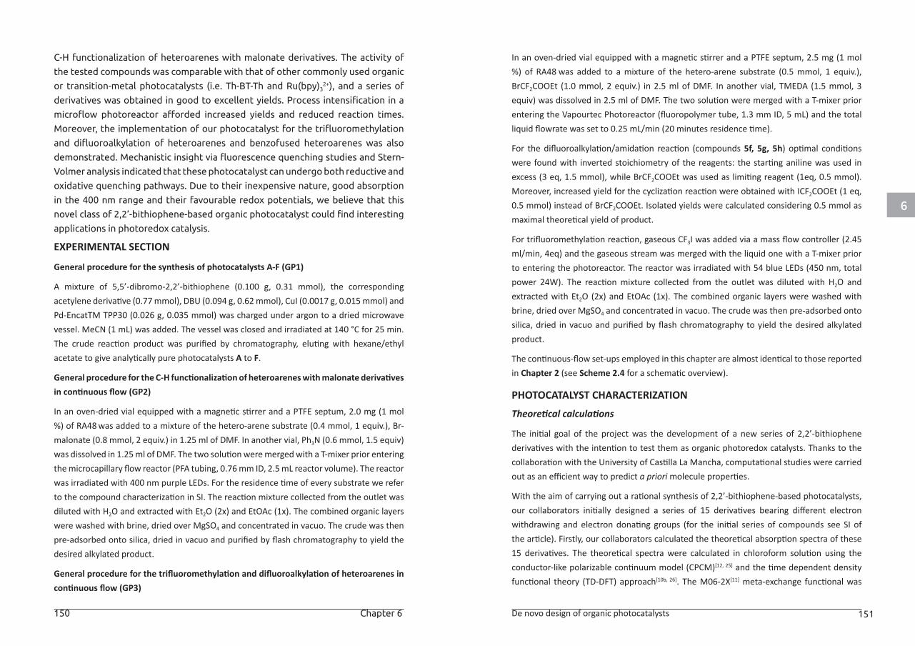
6
150 Chapter 6 De novo design of organic photocatalysts 151
C-H functionalization of heteroarenes with malonate derivatives. The activity of
the tested compounds was comparable with that of other commonly used organic
or transition-metal photocatalysts (i.e. Th-BT-Th and Ru(bpy)32+), and a series of
derivatives was obtained in good to excellent yields. Process intensification in a
microflow photoreactor afforded increased yields and reduced reaction times.
Moreover, the implementation of our photocatalyst for the trifluoromethylation
and difluoroalkylation of heteroarenes and benzofused heteroarenes was also
demonstrated. Mechanistic insight via fluorescence quenching studies and Stern-
Volmer analysis indicated that these photocatalyst can undergo both reductive and
oxidative quenching pathways. Due to their inexpensive nature, good absorption
in the 400 nm range and their favourable redox potentials, we believe that this
novel class of 2,2’-bithiophene-based organic photocatalyst could find interesting
applications in photoredox catalysis.
EXPERIMENTAL SECTION
General procedure for the synthesis of photocatalysts A-F (GP1)
A mixture of 5,5’-dibromo-2,2’-bithiophene (0.100 g, 0.31 mmol), the corresponding acetylene derivative (0.77 mmol), DBU (0.094 g, 0.62 mmol), CuI (0.0017 g, 0.015 mmol) and Pd-EncatTM TPP30 (0.026 g, 0.035 mmol) was charged under argon to a dried microwave vessel. MeCN (1 mL) was added. The vessel was closed and irradiated at 140 °C for 25 min. The crude reaction product was purified by chromatography, eluting with hexane/ethyl acetate to give analytically pure photocatalysts A to F.
General procedure for the C-H functionalization of heteroarenes with malonate derivatives in continuous flow (GP2)
In an oven-dried vial equipped with a magnetic stirrer and a PTFE septum, 2.0 mg (1 mol %) of RA48 was added to a mixture of the hetero-arene substrate (0.4 mmol, 1 equiv.), Br-malonate (0.8 mmol, 2 equiv.) in 1.25 ml of DMF. In another vial, Ph3N (0.6 mmol, 1.5 equiv) was dissolved in 1.25 ml of DMF. The two solution were merged with a T-mixer prior entering the microcapillary flow reactor (PFA tubing, 0.76 mm ID, 2.5 mL reactor volume). The reactor was irradiated with 400 nm purple LEDs. For the residence time of every substrate we refer to the compound characterization in SI. The reaction mixture collected from the outlet was diluted with H2O and extracted with Et2O (2x) and EtOAc (1x). The combined organic layers were washed with brine, dried over MgSO4 and concentrated in vacuo. The crude was then pre-adsorbed onto silica, dried in vacuo and purified by flash chromatography to yield the desired alkylated product.
General procedure for the trifluoromethylation and difluoroalkylation of heteroarenes in continuous flow (GP3)
In an oven-dried vial equipped with a magnetic stirrer and a PTFE septum, 2.5 mg (1 mol %) of RA48 was added to a mixture of the hetero-arene substrate (0.5 mmol, 1 equiv.), BrCF2COOEt (1.0 mmol, 2 equiv.) in 2.5 ml of DMF. In another vial, TMEDA (1.5 mmol, 3 equiv) was dissolved in 2.5 ml of DMF. The two solution were merged with a T-mixer prior entering the Vapourtec Photoreactor (fluoropolymer tube, 1.3 mm ID, 5 mL) and the total liquid flowrate was set to 0.25 mL/min (20 minutes residence time).
For the difluoroalkylation/amidation reaction (compounds 5f, 5g, 5h) optimal conditions were found with inverted stoichiometry of the reagents: the starting aniline was used in excess (3 eq, 1.5 mmol), while BrCF2COOEt was used as limiting reagent (1eq, 0.5 mmol). Moreover, increased yield for the cyclization reaction were obtained with ICF2COOEt (1 eq, 0.5 mmol) instead of BrCF2COOEt. Isolated yields were calculated considering 0.5 mmol as maximal theoretical yield of product.
For trifluoromethylation reaction, gaseous CF3I was added via a mass flow controller (2.45 ml/min, 4eq) and the gaseous stream was merged with the liquid one with a T-mixer prior to entering the photoreactor. The reactor was irradiated with 54 blue LEDs (450 nm, total power 24W). The reaction mixture collected from the outlet was diluted with H2O and extracted with Et2O (2x) and EtOAc (1x). The combined organic layers were washed with brine, dried over MgSO4 and concentrated in vacuo. The crude was then pre-adsorbed onto silica, dried in vacuo and purified by flash chromatography to yield the desired alkylated product.
The continuous-flow set-ups employed in this chapter are almost identical to those reported in Chapter 2 (see Scheme 2.4 for a schematic overview).
PHOTOCATALYST CHARACTERIZATION
Theoretical calculations
The initial goal of the project was the development of a new series of 2,2’-bithiophene derivatives with the intention to test them as organic photoredox catalysts. Thanks to the collaboration with the University of Castilla La Mancha, computational studies were carried out as an efficient way to predict a priori molecule properties.
With the aim of carrying out a rational synthesis of 2,2’-bithiophene-based photocatalysts, our collaborators initially designed a series of 15 derivatives bearing different electron withdrawing and electron donating groups (for the initial series of compounds see SI of the article). Firstly, our collaborators calculated the theoretical absorption spectra of these 15 derivatives. The theoretical spectra were calculated in chloroform solution using the conductor-like polarizable continuum model (CPCM)[12, 25] and the time dependent density functional theory (TD-DFT) approach[10b, 26]. The M06-2X[11] meta-exchange functional was
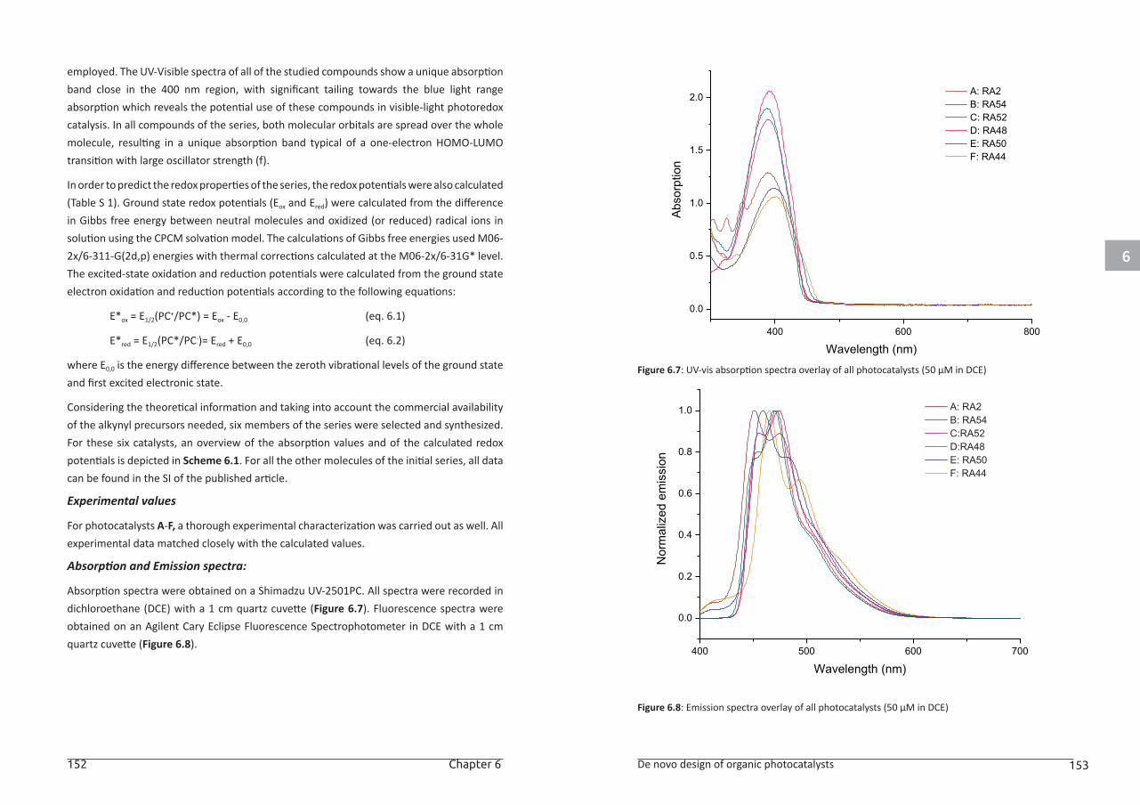
6
152 Chapter 6 De novo design of organic photocatalysts 153
employed. The UV-Visible spectra of all of the studied compounds show a unique absorption band close in the 400 nm region, with significant tailing towards the blue light range absorption which reveals the potential use of these compounds in visible-light photoredox catalysis. In all compounds of the series, both molecular orbitals are spread over the whole molecule, resulting in a unique absorption band typical of a one-electron HOMO-LUMO transition with large oscillator strength (f).
In order to predict the redox properties of the series, the redox potentials were also calculated (Table S 1). Ground state redox potentials (Eox and Ered) were calculated from the difference in Gibbs free energy between neutral molecules and oxidized (or reduced) radical ions in solution using the CPCM solvation model. The calculations of Gibbs free energies used M06-2x/6-311-G(2d,p) energies with thermal corrections calculated at the M06-2x/6-31G* level. The excited-state oxidation and reduction potentials were calculated from the ground state electron oxidation and reduction potentials according to the following equations:
E*ox = E1/2(PC+/PC*) = Eox - E0,0 (eq. 6.1)
E*red = E1/2(PC*/PC-)= Ered + E0,0 (eq. 6.2)
where E0,0 is the energy difference between the zeroth vibrational levels of the ground state and first excited electronic state.
Considering the theoretical information and taking into account the commercial availability of the alkynyl precursors needed, six members of the series were selected and synthesized. For these six catalysts, an overview of the absorption values and of the calculated redox potentials is depicted in Scheme 6.1. For all the other molecules of the initial series, all data can be found in the SI of the published article.
Experimental values
For photocatalysts A-F, a thorough experimental characterization was carried out as well. All experimental data matched closely with the calculated values.
Absorption and Emission spectra:
Absorption spectra were obtained on a Shimadzu UV-2501PC. All spectra were recorded in dichloroethane (DCE) with a 1 cm quartz cuvette (Figure 6.7). Fluorescence spectra were obtained on an Agilent Cary Eclipse Fluorescence Spectrophotometer in DCE with a 1 cm quartz cuvette (Figure 6.8).
Figure 6.7: UV-vis absorption spectra overlay of all photocatalysts (50 µM in DCE)
Figure 6.8: Emission spectra overlay of all photocatalysts (50 µM in DCE)
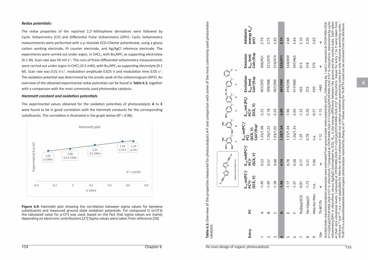
6
154 Chapter 6 De novo design of organic photocatalysts 155
Redox potentials:
The redox properties of the reported 2,2’-bithiophene derivatives were followed by Cyclic Voltammetry (CV) and Differential Pulse Voltammetry (DPV). Cyclic Voltammetry measurements were performed with a µ−Autolab ECO-Chemie potentiostat, using a glassy carbon working electrode, Pt counter electrode, and Ag/AgCl reference electrode. The experiments were carried out under argon, in CHCl3, with Bu4NPF6 as supporting electrolyte (0.1 M). Scan rate was 50 mV·s-1. The runs of Pulse differential voltammetry measurements were carried out under argon in CHCl3 (0.5·mM), with Bu4NPF6 as supporting electrolyte (0.1 M). Scan rate was 0.01 V·s-1, modulation amplitude 0.025 V and modulation time 0.05 s-1. The oxidation potential was determined by the anodic peak of the voltammogram (DPV). An overview of the obtained experimental redox potentials can be found in Table 6.3, together with a comparison with the most commonly used photoredox catalysts.
Hammett constant and oxidation potentials
The experimental values obtained for the oxidation potentials of photocatalysts A to E were found to be in good correlation with the Hammett constants for the corresponding substituents. The correlation is illustrated in the graph below (R2 = 0.98).
Figure 6.9: Hammett plot showing the correlation between sigma values for benzene substituents and measured ground state oxidation potentials. For compound D (o-CF3) the tabulated value for p-CF3 was used, based on the fact that sigma values are mainly depending on electronic contributions.[27] Sigma values were taken from reference [28]
1,083,4,5-OMe
1,223,5-OMe
1,02p-OMe
1,34o-CF3
1,34p-CN
R² = 0,9787
-0,4 -0,2 0 0,2 0,4 0,6 0,8
Expe
rimet
nal E
ox (V
)
σ value
Hammett plot
Tab
le 6
.3: O
verv
iew
of
the
pro
per
ties
mea
sure
d f
or
pho
toca
taly
sts
A-F
and
co
mp
aris
on
wit
h so
me
of
the
mo
st c
om
mo
nly
used
pho
tore
dox
ca
taly
sts.
Ent
ryP
CE
1/2 ox
(PC
+ /P
C*)
a
(SC
E, V
)
E1/
2 re
d(P
C*/
PC
- )a
(SC
E, V
)
E1/
2 o
x(P
C+ /
PC
)(S
CE
, V)
Cal
cb /E
xpc
E1/
2 re
d (
PC
/P
C- )b
(SC
E, V
)
Exc
itat
ion
λ max
(nm
)C
alcb /
Exp
Em
issi
on
λ max
(nm
)C
alcc /
Exp
Ad
iab
atic
en
ergy
E0,
0d
(eV
)
1A
-1.4
90.
531.
25/1
.08
-2.2
240
1/39
350
6/45
12.
74
2B
-1.4
90.
571.
26/1
.22
-2.1
839
9/38
852
1/47
02.
75
3C
-1.3
80.
681.
03/1
.02
-2.2
440
7/39
051
0/47
42.
65
4D
-1.4
60.
741.
28/1
.34
-2.0
040
1/39
052
2/47
12.
74
5E
-1.1
70.
781.
51/1
.34
-1.9
041
0/39
853
4/45
92.
68
6F
-1.3
70.
581.
26/1
.33
-2.0
541
7/40
054
7/46
52.
63
7R
u(b
py)3
Cl2
-0.8
10.
771.
29-1
.33
452
615
2.10
8fa
c-Ir
(ppy
)3-1
.73
0.31
0.78
-2.2
037
551
82.
50
9M
es-A
cr-M
e+n.
a.2.
06n.
a.-0
.57
430
570
2.63
10e
Th-B
T-Th
-e-e
1.12
-1.1
5~4
65-e
-ea E
xcit
ed s
tate
red
ucti
on/
oxid
atio
n p
ote
ntia
ls w
ere
esti
mat
ed f
rom
gro
und
sta
te r
edox
po
tent
ials
and
E0,
0 fo
llow
ing
eq
. 1 a
nd 2
co
mp
uted
at
CP
CM
-M06
-2X
/6-
311+
G(2
d,p
)//C
PC
M-M
06-2
X/6
-31G
* in
chl
oro
form
; b C
om
put
ed a
t C
PC
M-M
06-2
X/6
-311
+G(2
d,p
)//C
PC
M-M
06-2
X/6
-31G
* in
chl
oro
form
; c Det
erm
ined
by
cycl
ic
volt
amm
etry
/DP
V i
n ch
loro
form
ver
sus
Ag
/Ag
Cl
(no
rmal
ized
to
SC
E);
dE 0
,0 i
s th
e en
erg
y d
iffer
ence
bet
wee
n th
e g
roun
d a
nd t
he e
xcit
ed s
tate
, b
oth
tak
en
at t
heir
zer
o v
ibra
tio
nal
leve
ls.
Co
mp
uted
at
CP
CM
-M06
-2X
/6-3
11+G
(2d
,p)/
/CP
CM
-M06
-2X
/6-3
1G*
in c
hlo
rofo
rm.
Val
ues
for
entr
y 7
to 9
wer
e ta
ken
fro
m
refe
renc
e [4
] and
[29]
, n.a
. = n
ot
app
licab
le f
or
Mes
-Acr
as
this
co
mp
oun
d d
oes
no
t un
der
go
oxi
dat
ive
que
nchi
ng c
ycle
s b
ut o
nly
red
ucti
ve q
uenc
hing
cyc
les.
e
Th-B
T-Th
is a
ben
zoth
iad
iazo
le-b
ased
org
anic
pho
toca
taly
st r
epo
rted
by
Zhan
g e
t al
.[9] V
alue
s m
issi
ng f
or
Th-B
T-Th
co
uld
no
t b
e re
trie
ved
fro
m t
he li
tera
ture
.
S
S
R
R
AOMe
MeO
MeO
Organicphotocatalystcore
F:D:
E:
NC
C:
MeO
B:OMe
MeO
S
CF 3
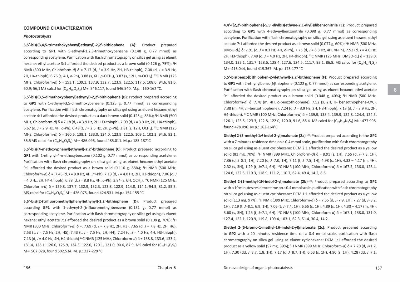
6
156 Chapter 6 De novo design of organic photocatalysts 157
COMPOUND CHARACTERIZATION
Photocatalysts
5,5’-bis((3,4,5-trimethoxyphenyl)ethynyl)-2,2’-bithiophene (A): Product prepared according to GP1 with 5-ethynyl-1,2,3-trimethoxybenzene (0.148 g, 0.77 mmol) as corresponding acetylene. Purification with flash chromatography on silica gel using as eluent hexane: ethyl acetate 3:1 afforded the desired product as a brown solid (0.126 g, 75%); 1H NMR (500 MHz, Chloroform-d) δ = 7.17 (d, J = 3.9 Hz, 2H, H3-thioph), 7.08 (d, J = 3.9 Hz, 2H, H4-thioph), 6.76 (s, 4H, o-Ph), 3.88 (s, 6H, p-OCH3), 3.87 (s, 12H, m-OCH3). 13C NMR (125 MHz, Chloroform-d) δ = 153,1; 139,1; 137,9; 132,7; 123,9; 122,5; 117,6; 108,6; 94,6, 81,6, 60,9; 56,1 MS calcd for (C26H18O2S2) M+· 546.117, found 546.540. M.p.: 160-162 °C.
5,5’-bis((3,5-dimethoxyphenyl)ethynyl)-2,2’-bithiophene (B): Product prepared according to GP1 with 1-ethynyl-3,5-dimethoxybenzene (0.125 g, 0.77 mmol) as corresponding acetylene. Purification with flash chromatography on silica gel using as eluent hexane: ethyl acetate 4:1 afforded the desired product as a dark brown solid (0.125 g, 83%); 1H NMR (500 MHz, Chloroform-d) δ = 7.18 (d, J = 3.9 Hz, 2H, H3-thioph), 7.09 (d, J = 3.9 Hz, 2H, H4-thioph), 6.67 (d, J = 2.9 Hz, 4H, o-Ph), 6.48 (t, J = 2.5 Hz, 2H, p-Ph), 3.81 (s, 12H, OCH3). 13C NMR (125 MHz, Chloroform-d) δ = 160.6, 138.1, 133.0, 124.0, 123.9, 122.5, 109.1, 102.2, 94.6, 82.1, 55.5 MS calcd for (C28H22O4S2) M+· 486.096, found 485.011. M.p.: 185-187°C
5,5’-bis((4-methoxyphenyl)ethynyl)-2,2’-bithiophene (C): Product prepared according to GP1 with 1-ethynyl-4-methoxybenzene (0.102 g, 0.77 mmol) as corresponding acetylene. Purification with flash chromatography on silica gel using as eluent hexane: ethyl acetate 9:1 afforded the desired product as a brown solid (0.116 g, 88%); 1H NMR (500 MHz, Chloroform-d) δ =. 7.45 (d, J = 8.8 Hz, 4H, m-Ph), 7.13 (d, J = 4.0 Hz, 2H, H3-thioph), 7.06 (d, J = 4.0 Hz, 2H, H4-thioph), 6.88 (d, J = 8.8 Hz, 4H, o-Ph), 3.84 (s, 6H, OCH3). 13C NMR (125 MHz, Chloroform-d) δ = 159.8, 137.7, 132.9, 132.3, 123.8, 122.9, 114.8, 114.1, 94.5, 81.2, 55.3. MS calcd for (C26H18O2S2) M+· 426.075, found 424.531. M.p.: 154-155 °C
5,5’-bis((2-(trifluoromethyl)phenyl)ethynyl)-2,2’-bithiophene (D): Product prepared according GP1 with 1-ethynyl-2-(trifluoromethyl)benzene (0.131 g, 0.77 mmol) as corresponding acetylene. Purification with flash chromatography on silica gel using as eluent hexane: ethyl acetate 7:1 afforded the desired product as a brown solid (0.108 g, 70%); 1H NMR (500 MHz, Chloroform-d) δ =. 7.69 (d, J = 7.8 Hz, 2H, H3), 7.65 (d, J = 7.8 Hz, 2H, H6), 7.53 (t, J = 7.5 Hz, 2H, H5), 7.43 (t, J = 7.5 Hz, 2H, H4), 7.24 (d, J = 4.0 Hz, 4H, H3-thioph), 7.13 (d, J = 4.0 Hz, 4H, H4-thioph) 13C NMR (125 MHz, Chloroform-d) δ = 138.8, 133.6, 133.4, 131.4, 128.1, 126.0, 125.9, 124.3, 122.0, 120.1, 121.0, 90.6, 87.9. MS calcd for (C26H12F6S2) M+· 502.028, found 502.534. M. p.: 227-229 °C
4,4’-([2,2’-bithiophene]-5,5’-diylbis(ethyne-2,1-diyl))dibenzonitrile (E): Product prepared according to GP1 with 4-ethynylbenzonitrile (0.098 g, 0.77 mmol) as corresponding acetylene. Purification with flash chromatography on silica gel using as eluent hexane: ethyl acetate 7:1 afforded the desired product as a brown solid (0.077 g, 60%); 1H NMR (500 MHz, DMSO-d6) δ: 7.91 (d, J = 8.3 Hz, 4H, o-Ph), 7.75 (d, J = 8.3 Hz, 4H, m-Ph), 7.52 (d, J = 4.0 Hz, 2H, H3-thioph), 7.49 (d, J = 4.0 Hz, 2H, H4-thioph). 13C NMR (125 MHz, DMSO-d6) δ = 139.0, 134.0, 132.1, 131.7, 128.6, 128.4, 127.6, 124.5, 111.7, 93.1, 86.8. MS calcd for (C26H12N2S2) M+· 416.044, found 419.367. M. p.: 175-177 °C
5,5’-bis(benzo[b]thiophen-2-ylethynyl)-2,2’-bithiophene (F): Product prepared according to GP1 with 2-ethynylbenzo[b]thiophene (0.122 g, 0.77 mmol) as corresponding acetylene. Purification with flash chromatography on silica gel using as eluent hexane: ethyl acetate 9:1 afforded the desired product as a brown solid (0.048 g, 40%); 1H NMR (500 MHz, Chloroform-d) δ: 7.78 (m, 4H, o-benzothiophene), 7.52 (s, 2H, H- benzothiophene-C≡C), 7.38 (m, 4H, m-benzothiophene), 7.24 (d, J = 3.9 Hz, 2H, H3-thioph), 7.13 (d, J = 3.9 Hz, 2H, H4-thioph). 13C NMR (100 MHz, Chloroform-d) δ = 139.9, 138.4, 139.9, 132.8, 124.4, 124.3, 126.1, 123.5, 123.3, 122.8, 122.0, 120.0, 91.6, 86.4. MS calcd for (C26H12N2S2) M+· 477.998, found 478.096. M.p.: 162-164°C
Diethyl 2-(3-methyl-1H-indol-2-yl)malonate (2a)[15]: Product prepared according to the GP2 with a 7 minutes residence time on a 0.4 mmol scale, purification with flash chromatography on silica gel using as eluent cyclohexane: DCM 2:1 afforded the desired product as a yellow solid (81 mg, 70%); 1H NMR (399 MHz, Chloroform-d) δ = 8.91 (s, 1H), 7.55 (d, J=7.8, 1H), 7.36 (d, J=8.1, 1H), 7.20 (d, J=7.0, 1H), 7.11 (t, J=7.5, 1H), 4.98 (s, 1H), 4.32 – 4.17 (m, 4H), 2.32 (s, 3H), 1.29 (t, J=7.1, 6H). 13C NMR (100 MHz, Chloroform-d) δ = 167.5, 136.0, 128.4, 124.6, 122.5, 119.3, 118.9, 111.2, 110.7, 62.4, 49.4, 14.2, 8.6.
Diethyl 2-(1-methyl-1H-indol-2-yl)malonate (2b)[15]: Product prepared according to GP2 with a 10 minutes residence time on a 0.4 mmol scale, purification with flash chromatography on silica gel using as eluent cyclohexane: DCM 1:1 afforded the desired product as a yellow solid (113 mg, 97%); 1H NMR (399 MHz, Chloroform-d) δ = 7.55 (d, J=7.9, 1H), 7.27 (d, J=8.2, 1H), 7.19 (t, J=8.1, 6.9, 1H), 7.06 (t, J=7.4, 1H), 6.55 (s, 1H), 4.89 (s, 1H), 4.30 – 4.17 (m, 4H), 3.68 (s, 3H), 1.26 (t, J=7.1, 6H). 13C NMR (100 MHz, Chloroform-d) δ = 167.1, 138.0, 131.0, 127.4, 122.1, 120.9, 119.8, 109.4, 103.1, 62.3, 51.4, 30.4, 14.2.
Diethyl 2-(5-bromo-1-methyl-1H-indol-2-yl)malonate (2c): Product prepared according to GP2 with a 20 minutes residence time on a 0.4 mmol scale, purification with flash chromatography on silica gel using as eluent cyclohexane: DCM 1:1 afforded the desired product as a yellow solid (57 mg, 39%); 1H NMR (399 MHz, Chloroform-d) δ = 7.70 (d, J=1.7, 1H), 7.30 (dd, J=8.7, 1.8, 1H), 7.17 (d, J=8.7, 1H), 6.53 (s, 1H), 4.90 (s, 1H), 4.28 (dd, J=7.1,
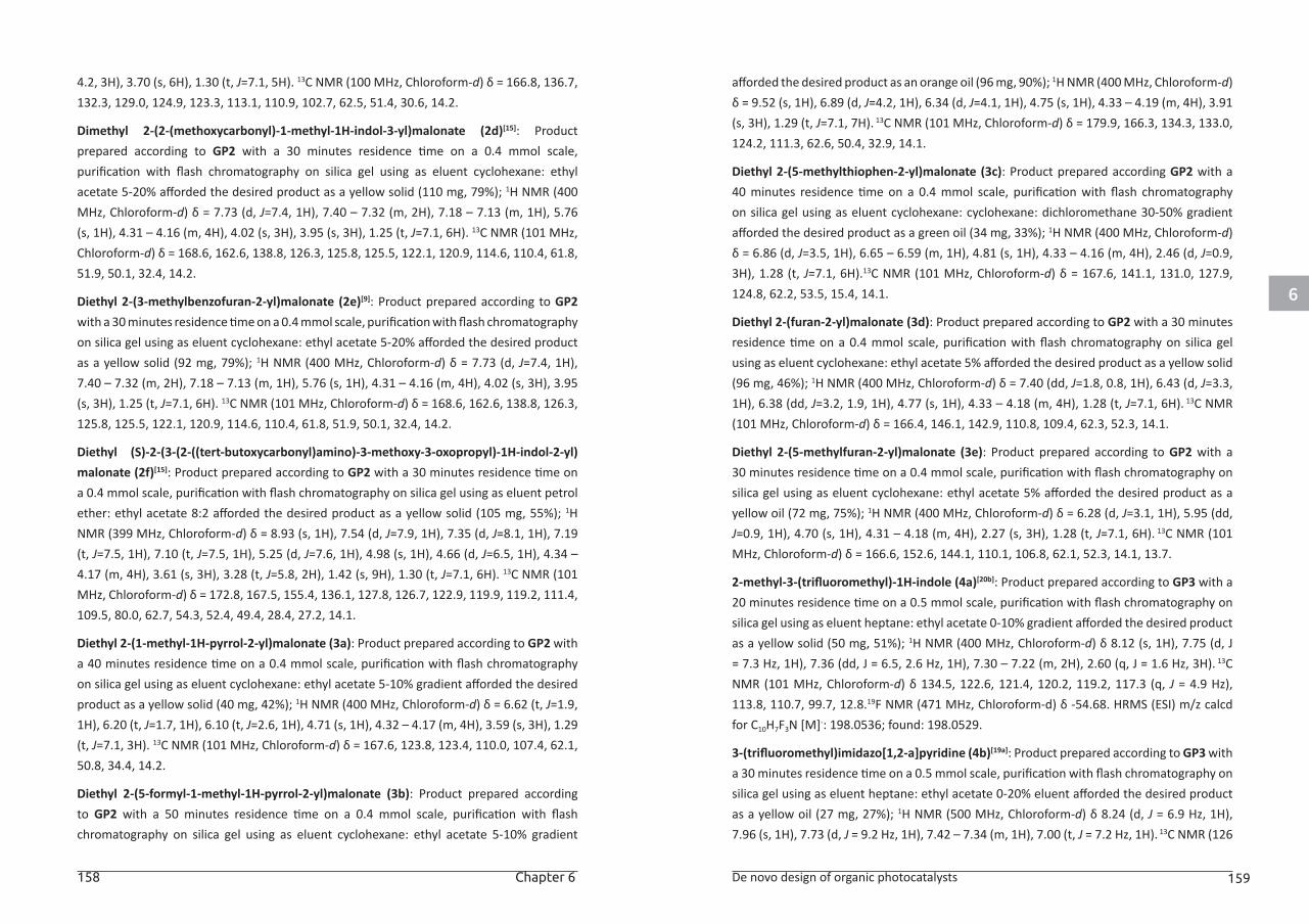
6
158 Chapter 6 De novo design of organic photocatalysts 159
4.2, 3H), 3.70 (s, 6H), 1.30 (t, J=7.1, 5H). 13C NMR (100 MHz, Chloroform-d) δ = 166.8, 136.7, 132.3, 129.0, 124.9, 123.3, 113.1, 110.9, 102.7, 62.5, 51.4, 30.6, 14.2.
Dimethyl 2-(2-(methoxycarbonyl)-1-methyl-1H-indol-3-yl)malonate (2d)[15]: Product prepared according to GP2 with a 30 minutes residence time on a 0.4 mmol scale, purification with flash chromatography on silica gel using as eluent cyclohexane: ethyl acetate 5-20% afforded the desired product as a yellow solid (110 mg, 79%); 1H NMR (400 MHz, Chloroform-d) δ = 7.73 (d, J=7.4, 1H), 7.40 – 7.32 (m, 2H), 7.18 – 7.13 (m, 1H), 5.76 (s, 1H), 4.31 – 4.16 (m, 4H), 4.02 (s, 3H), 3.95 (s, 3H), 1.25 (t, J=7.1, 6H). 13C NMR (101 MHz, Chloroform-d) δ = 168.6, 162.6, 138.8, 126.3, 125.8, 125.5, 122.1, 120.9, 114.6, 110.4, 61.8, 51.9, 50.1, 32.4, 14.2.
Diethyl 2-(3-methylbenzofuran-2-yl)malonate (2e)[9]: Product prepared according to GP2 with a 30 minutes residence time on a 0.4 mmol scale, purification with flash chromatography on silica gel using as eluent cyclohexane: ethyl acetate 5-20% afforded the desired product as a yellow solid (92 mg, 79%); 1H NMR (400 MHz, Chloroform-d) δ = 7.73 (d, J=7.4, 1H), 7.40 – 7.32 (m, 2H), 7.18 – 7.13 (m, 1H), 5.76 (s, 1H), 4.31 – 4.16 (m, 4H), 4.02 (s, 3H), 3.95 (s, 3H), 1.25 (t, J=7.1, 6H). 13C NMR (101 MHz, Chloroform-d) δ = 168.6, 162.6, 138.8, 126.3, 125.8, 125.5, 122.1, 120.9, 114.6, 110.4, 61.8, 51.9, 50.1, 32.4, 14.2.
Diethyl (S)-2-(3-(2-((tert-butoxycarbonyl)amino)-3-methoxy-3-oxopropyl)-1H-indol-2-yl)malonate (2f)[15]: Product prepared according to GP2 with a 30 minutes residence time on a 0.4 mmol scale, purification with flash chromatography on silica gel using as eluent petrol ether: ethyl acetate 8:2 afforded the desired product as a yellow solid (105 mg, 55%); 1H NMR (399 MHz, Chloroform-d) δ = 8.93 (s, 1H), 7.54 (d, J=7.9, 1H), 7.35 (d, J=8.1, 1H), 7.19 (t, J=7.5, 1H), 7.10 (t, J=7.5, 1H), 5.25 (d, J=7.6, 1H), 4.98 (s, 1H), 4.66 (d, J=6.5, 1H), 4.34 – 4.17 (m, 4H), 3.61 (s, 3H), 3.28 (t, J=5.8, 2H), 1.42 (s, 9H), 1.30 (t, J=7.1, 6H). 13C NMR (101 MHz, Chloroform-d) δ = 172.8, 167.5, 155.4, 136.1, 127.8, 126.7, 122.9, 119.9, 119.2, 111.4, 109.5, 80.0, 62.7, 54.3, 52.4, 49.4, 28.4, 27.2, 14.1.
Diethyl 2-(1-methyl-1H-pyrrol-2-yl)malonate (3a): Product prepared according to GP2 with a 40 minutes residence time on a 0.4 mmol scale, purification with flash chromatography on silica gel using as eluent cyclohexane: ethyl acetate 5-10% gradient afforded the desired product as a yellow solid (40 mg, 42%); 1H NMR (400 MHz, Chloroform-d) δ = 6.62 (t, J=1.9, 1H), 6.20 (t, J=1.7, 1H), 6.10 (t, J=2.6, 1H), 4.71 (s, 1H), 4.32 – 4.17 (m, 4H), 3.59 (s, 3H), 1.29 (t, J=7.1, 3H). 13C NMR (101 MHz, Chloroform-d) δ = 167.6, 123.8, 123.4, 110.0, 107.4, 62.1, 50.8, 34.4, 14.2.
Diethyl 2-(5-formyl-1-methyl-1H-pyrrol-2-yl)malonate (3b): Product prepared according to GP2 with a 50 minutes residence time on a 0.4 mmol scale, purification with flash chromatography on silica gel using as eluent cyclohexane: ethyl acetate 5-10% gradient
afforded the desired product as an orange oil (96 mg, 90%); 1H NMR (400 MHz, Chloroform-d) δ = 9.52 (s, 1H), 6.89 (d, J=4.2, 1H), 6.34 (d, J=4.1, 1H), 4.75 (s, 1H), 4.33 – 4.19 (m, 4H), 3.91 (s, 3H), 1.29 (t, J=7.1, 7H). 13C NMR (101 MHz, Chloroform-d) δ = 179.9, 166.3, 134.3, 133.0, 124.2, 111.3, 62.6, 50.4, 32.9, 14.1.
Diethyl 2-(5-methylthiophen-2-yl)malonate (3c): Product prepared according GP2 with a 40 minutes residence time on a 0.4 mmol scale, purification with flash chromatography on silica gel using as eluent cyclohexane: cyclohexane: dichloromethane 30-50% gradient afforded the desired product as a green oil (34 mg, 33%); 1H NMR (400 MHz, Chloroform-d) δ = 6.86 (d, J=3.5, 1H), 6.65 – 6.59 (m, 1H), 4.81 (s, 1H), 4.33 – 4.16 (m, 4H), 2.46 (d, J=0.9, 3H), 1.28 (t, J=7.1, 6H).13C NMR (101 MHz, Chloroform-d) δ = 167.6, 141.1, 131.0, 127.9, 124.8, 62.2, 53.5, 15.4, 14.1.
Diethyl 2-(furan-2-yl)malonate (3d): Product prepared according to GP2 with a 30 minutes residence time on a 0.4 mmol scale, purification with flash chromatography on silica gel using as eluent cyclohexane: ethyl acetate 5% afforded the desired product as a yellow solid (96 mg, 46%); 1H NMR (400 MHz, Chloroform-d) δ = 7.40 (dd, J=1.8, 0.8, 1H), 6.43 (d, J=3.3, 1H), 6.38 (dd, J=3.2, 1.9, 1H), 4.77 (s, 1H), 4.33 – 4.18 (m, 4H), 1.28 (t, J=7.1, 6H). 13C NMR (101 MHz, Chloroform-d) δ = 166.4, 146.1, 142.9, 110.8, 109.4, 62.3, 52.3, 14.1.
Diethyl 2-(5-methylfuran-2-yl)malonate (3e): Product prepared according to GP2 with a 30 minutes residence time on a 0.4 mmol scale, purification with flash chromatography on silica gel using as eluent cyclohexane: ethyl acetate 5% afforded the desired product as a yellow oil (72 mg, 75%); 1H NMR (400 MHz, Chloroform-d) δ = 6.28 (d, J=3.1, 1H), 5.95 (dd, J=0.9, 1H), 4.70 (s, 1H), 4.31 – 4.18 (m, 4H), 2.27 (s, 3H), 1.28 (t, J=7.1, 6H). 13C NMR (101 MHz, Chloroform-d) δ = 166.6, 152.6, 144.1, 110.1, 106.8, 62.1, 52.3, 14.1, 13.7.
2-methyl-3-(trifluoromethyl)-1H-indole (4a)[20b]: Product prepared according to GP3 with a 20 minutes residence time on a 0.5 mmol scale, purification with flash chromatography on silica gel using as eluent heptane: ethyl acetate 0-10% gradient afforded the desired product as a yellow solid (50 mg, 51%); 1H NMR (400 MHz, Chloroform-d) δ 8.12 (s, 1H), 7.75 (d, J = 7.3 Hz, 1H), 7.36 (dd, J = 6.5, 2.6 Hz, 1H), 7.30 – 7.22 (m, 2H), 2.60 (q, J = 1.6 Hz, 3H). 13C NMR (101 MHz, Chloroform-d) δ 134.5, 122.6, 121.4, 120.2, 119.2, 117.3 (q, J = 4.9 Hz), 113.8, 110.7, 99.7, 12.8.19F NMR (471 MHz, Chloroform-d) δ -54.68. HRMS (ESI) m/z calcd for C10H7F3N [M]-: 198.0536; found: 198.0529.
3-(trifluoromethyl)imidazo[1,2-a]pyridine (4b)[19a]: Product prepared according to GP3 with a 30 minutes residence time on a 0.5 mmol scale, purification with flash chromatography on silica gel using as eluent heptane: ethyl acetate 0-20% eluent afforded the desired product as a yellow oil (27 mg, 27%); 1H NMR (500 MHz, Chloroform-d) δ 8.24 (d, J = 6.9 Hz, 1H), 7.96 (s, 1H), 7.73 (d, J = 9.2 Hz, 1H), 7.42 – 7.34 (m, 1H), 7.00 (t, J = 7.2 Hz, 1H). 13C NMR (126
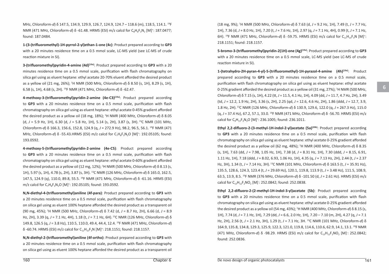
6
160 Chapter 6 De novo design of organic photocatalysts 161
MHz, Chloroform-d) δ 147.5, 134.9, 129.9, 126.7, 124.9, 124.7 – 118.6 (m), 118.5, 114.1. 19F NMR (471 MHz, Chloroform-d) δ -61.48. HRMS (ESI) m/z calcd for C8H6F3N2 [M]+: 187.0477; found: 187.0484.
1-(3-(trifluoromethyl)-1H-pyrrol-2-yl)ethan-1-one (4c): Product prepared according to GP3 with a 20 minutes residence time on a 0.5 mmol scale, LC-MS yield (see LC-MS of crude reaction mixture in SI).
3-(trifluoromethyl)pyridin-4-amine (4d)[19a]: Product prepared according to GP3 with a 20 minutes residence time on a 0.5 mmol scale, purification with flash chromatography on silica gel using as eluent heptane: ethyl acetate 20-70% eluent afforded the desired product as a yellow oil (21 mg, 26%); 1H NMR (500 MHz, Chloroform-d) δ 8.50 (s, 1H), 8.29 (s, 1H), 6.58 (s, 1H), 4.68 (s, 2H). 19F NMR (471 MHz, Chloroform-d) δ -62.47.
4-methoxy-3-(trifluoromethyl)pyridin-2-amine (4e-C3)[19a]: Product prepared according to GP3 with a 20 minutes residence time on a 0.5 mmol scale, purification with flash chromatography on silica gel using as eluent heptane: ethyl acetate 0-45% gradient afforded the desired product as a yellow oil (18 mg, 18%); 1H NMR (400 MHz, Chloroform-d) δ 8.05 (d, J = 5.9 Hz, 1H), 6.30 (d, J = 5.8 Hz, 1H), 5.14 (s, 2H), 3.87 (s, 3H). 13C NMR (101 MHz, Chloroform-d) δ 166.3, 156.6, 152.8, 124.9 (q, J = 272.9 Hz), 98.2, 96.5, 56.1. 19F NMR (471 MHz, Chloroform-d) δ -55.43.HRMS (ESI) m/z calcd for C7H8F3N2O [M]+: 192.05105; found: 193.0592.
4-methoxy-5-(trifluoromethyl)pyridin-2-amine (4e-C5): Product prepared according to GP3 with a 20 minutes residence time on a 0.5 mmol scale, purification with flash chromatography on silica gel using as eluent heptane: ethyl acetate 0-60% gradient afforded the desired product as a yellow oil (12 mg, 12%); 1H NMR (500 MHz, Chloroform-d) δ 8.13 (s, 1H), 5.97 (s, 1H), 4.78 (s, 2H), 3.87 (s, 3H). 13C NMR (126 MHz, Chloroform-d) δ 165.0, 162.5, 147.5, 124.9 (q), 110.0, 89.8, 55.5. 19F NMR (471 MHz, Chloroform-d) δ -61.16. HRMS (ESI) m/z calcd for C7H8F3N2O [M]+: 192.05105; found: 193.0592.
N,N-diethyl-4-(trifluoromethyl)aniline (4f-para): Product prepared according to GP3 with a 20 minutes residence time on a 0.5 mmol scale, purification with flash chromatography on silica gel using as eluent 100% heptane afforded the desired product as a transparent oil (90 mg, 45%); 1H NMR (500 MHz, Chloroform-d) δ 7.42 (d, J = 8.7 Hz, 2H), 6.66 (d, J = 8.9 Hz, 2H), 3.39 (q, J = 7.1 Hz, 4H), 1.18 (t, J = 7.1 Hz, 6H). 13C NMR (126 MHz, Chloroform-d) δ 149.8, 126.5 (q, J = 3.8 Hz), 110.5, 110.0, 49.4, 44.4, 12.4. 19F NMR (471 MHz, Chloroform-d) δ -60.74. HRMS (ESI) m/z calcd for C11H15F3N [M]+: 218.1151; found: 218.1157.
N,N-diethyl-2-(trifluoromethyl)aniline (4f-ortho): Product prepared according to GP3 with a 20 minutes residence time on a 0.5 mmol scale, purification with flash chromatography on silica gel using as eluent 100% heptane afforded the desired product as a transparent oil
(18 mg, 9%); 1H NMR (500 MHz, Chloroform-d) δ 7.63 (d, J = 9.2 Hz, 1H), 7.49 (t, J = 7.7 Hz, 1H), 7.36 (d, J = 8.0 Hz, 1H), 7.20 (t, J = 7.6 Hz, 1H), 2.97 (q, J = 7.1 Hz, 4H), 0.99 (t, J = 7.1 Hz, 6H). 19F NMR (471 MHz, Chloroform-d) δ -59.75. HRMS (ESI) m/z calcd for C11H15F3N [M]+: 218.1151; found: 218.1157.
5-bromo-3-(trifluoromethyl)pyridin-2(1H)-one (4g)[19a]: Product prepared according to GP3 with a 20 minutes residence time on a 0.5 mmol scale, LC-MS yield (see LC-MS of crude reaction mixture in SI).
1-(tetrahydro-2H-pyran-4-yl)-5-(trifluoromethyl)-1H-pyrazol-4-amine (4h)[19a]: Product prepared according to GP3 with a 20 minutes residence time on a 0.5 mmol scale, purification with flash chromatography on silica gel using as eluent heptane: ethyl acetate 0-25% gradient afforded the desired product as a yellow oil (31 mg, 27%); 1H NMR (500 MHz, Chloroform-d) δ 7.15 (s, 1H), 4.22 (tt, J = 11.5, 4.1 Hz, 1H), 4.09 (dd, J = 11.7, 4.7 Hz, 2H), 3.49 (td, J = 12.2, 1.9 Hz, 2H), 3.36 (s, 2H), 2.25 (qd, J = 12.6, 4.6 Hz, 2H), 1.86 (ddd, J = 12.7, 3.9, 1.8 Hz, 2H). 13C NMR (126 MHz, Chloroform-d) δ 130.9, 129.6, 122.0 (q, J = 267.3 Hz), 115.0 (q, J = 37.4 Hz), 67.2, 57.1, 33.0. 19F NMR (471 MHz, Chloroform-d) δ -56.70. HRMS (ESI) m/z calcd for C9H13F3N3O [M]+: 236.1005; found: 236.1011.
Ethyl 2,2-difluoro-2-(3-methyl-1H-indol-2-yl)acetate (5a)[20b]: Product prepared according to GP3 with a 20 minutes residence time on a 0.5 mmol scale, purification with flash chromatography on silica gel using as eluent heptane: ethyl acetate 0-25% gradient afforded the desired product as a yellow oil (62 mg, 48%); 1H NMR (400 MHz, Chloroform-d) δ 8.35 (s, 1H), 7.63 (dd, J = 7.98, 1.05 Hz, 1H), 7.38 (d, J = 8.31 Hz, 1H), 7.30 (ddd, J = 8.15, 6.91, 1.11 Hz, 1H), 7.18 (ddd, J = 8.02, 6.93, 1.06 Hz, 1H), 4.35 (q, J = 7.13 Hz, 2H), 2.44 (t, J = 2.37 Hz, 3H), 1.34 (t, J = 7.14 Hz, 3H). 13C NMR (101 MHz, Chloroform-d) δ 163.5 (t, J = 35.91 Hz), 135.5, 128.6, 124.3, 123.4 (t, J = 29.69 Hz), 120.1, 119.8, 113.9 (t, J = 3.48 Hz), 111.5, 108.9, 63.5, 13.9, 8.5. 19F NMR (376 MHz, Chloroform-d) δ -101.50 (d, J = 2.61 Hz). HRMS (ESI) m/z calcd for C13H12F2NO2 [M]-: 252.0842; found: 252.0838.
Ethyl 2,2-difluoro-2-(2-methyl-1H-indol-3-yl)acetate (5b): Product prepared according to GP3 with a 20 minutes residence time on a 0.5 mmol scale, purification with flash chromatography on silica gel using as eluent heptane: ethyl acetate 0-25% gradient afforded the desired product as a yellow oil (54 mg, 43%); 1H NMR (400 MHz, Chloroform-d) δ 8.15 (s, 1H), 7.74 (d, J = 7.1 Hz, 1H), 7.29 (dd, J = 6.6, 2.0 Hz, 1H), 7.20 – 7.10 (m, 2H), 4.27 (q, J = 7.1 Hz, 2H), 2.56 (t, J = 2.1 Hz, 3H), 1.29 (t, J = 7.1 Hz, 3H. 13C NMR (101 MHz, Chloroform-d) δ 164.9, 135.8, 134.8, 129.3, 125.9, 122.3, 121.0, 119.8, 114.6, 110.6, 62.9, 14.1, 13.1. 19F NMR (471 MHz, Chloroform-d) δ -98.29. HRMS (ESI) m/z calcd for C13H12F2NO2 [M]-: 252.0842; found: 252.0836.
6
162 Chapter 6 De novo design of organic photocatalysts 163
Ethyl 2,2-difluoro-2-(imidazo[1,2-a]pyridin-3-yl)acetate (5c): Product prepared according to GP3 with a 20 minutes residence time on a 0.5 mmol scale, purification with flash chromatography on silica gel using as eluent heptane: ethyl acetate 0-20% gradient afforded the desired product as a yellow solid (58 mg, 49%); 1H NMR (500 MHz, Chloroform-d) δ 8.47 (d, J = 6.93 Hz, 1H), 7.89 (s, 1H), 7.76 (d, J = 7.69 Hz, 1H), 7.39 – 7.33 (m, 1H), 6.97 (t, J = 6.77 Hz, 1H), 4.40 (q, J = 7.15 Hz, 2H), 1.37 (t, J = 7.15 Hz, 3H). 13C NMR (101 MHz, Chloroform-d) δ 135.6 (t, J = 4.44 Hz), 126.6, 126.2 (t, J = 3.64 Hz), 118.4, 113.8, 113.7, 63.9, 22.8, 14.1 19F NMR (471 MHz, Chloroform-d) δ -101.75. HRMS (ESI) m/z calcd for C11H11F2N2O2 [M]+: 241.0783; found: 241.0426
Ethyl 2-(5-bromo-2-oxo-1,2-dihydropyridin-3-yl)-2,2-difluoroacetate (5d): Product prepared according to GP3 with a 20 minutes residence time on a 0.5 mmol scale, purification with flash chromatography on silica gel using as eluent heptane: ethyl acetate 25-50% gradient afforded the desired product as a yellow solid (73 mg, 50%); 1H NMR (500 MHz, Chloroform-d) δ 12.73 (s, 1H), 7.92 (d, J = 2.6 Hz, 1H), 7.74 (d, J = 2.2 Hz, 1H), 4.33 (q, J = 7.1 Hz, 2H), 1.30 (t, J = 7.1 Hz, 3H). 13C NMR (126 MHz, Chloroform-d) δ 162.7 (t, J = 33.0 Hz), 160.5 (t, J = 4.6 Hz), 142.6 (t, J = 7.2 Hz), 138.4, 125.4 (t, J = 24.7 Hz), 110.8 (t, J = 249.4 Hz), 98.7, 63.5, 14.0. 19F NMR (471 MHz, Chloroform-d) δ -106.57.HRMS (ESI) calculated for C9H7BrF2NO3 [M]-: 293.9578; found: 293.9519.
5-bromo-3-(1,1,2,2,3,3,4,4-octafluoropentyl)pyridin-2(1H)-one (5e): Product prepared according to GP3 with IC4F9 as fluorinating agent and a 20 minutes residence time on a 0.5 mmol scale, purification with flash chromatography on silica gel using as eluent cyclohexane: ethyl acetate 5-25% afforded the desired product as a yellow solid (43 mg, 22%); 1H NMR (500 MHz, Chloroform-d) δ 13.31 (s, 1H), 7.86 (d, J = 2.7 Hz, 1H), 7.75 (d, J = 2.7 Hz, 1H). 13C NMR (126 MHz, Chloroform-d) δ 160.1, 146.5 (t, J = 8.7 Hz), 140.2, 120.1 (t, J = 23.4 Hz), 118.6 (d, J = 32.5 Hz), 117.4 – 115.9 (m), 114.7 (t, J = 33.9 Hz), 113.7 – 112.4 (m), 97.9. 19F NMR (471 MHz, Chloroform-d) δ -80.87, -111.29, -121.74, -125.90. HRMS (ESI) calculated for C9H2BrF9NO [M]-: 389.9181; found: 389.9182.
3,3-difluoro-5-isopropylindolin-2-one (5f):[23] Product prepared according to GP3 with a 30 minutes residence time on a 0.5 mmol scale, purification with flash chromatography on silica gel using as eluent heptane: ethyl acetate 25% afforded the desired product as a transparent oil (29 mg, 27%); 1H NMR (500 MHz, Chloroform-d) δ 8.01 (s, 1H), 7.42 (d, J = 1.7 Hz, 1H), 7.30 (d, J = 9.2 Hz, 1H), 6.86 (d, J = 8.1 Hz, 1H), 2.92 (p, J = 6.9 Hz, 1H), 1.25 (d, J = 6.9 Hz, 6H). 13C NMR (126 MHz, Chloroform-d) δ 167.0, 145.4, 138.8, 131.8, 123.2, 121.2 – 120.0 (m), 113.1, 111.4, 33.9, 24.1.19F NMR (471 MHz, Chloroform-d) δ -111.34. HRMS (ESI) calculated for C11H10F2NO [M]-: 210.0735; found: 210.0733.
3,3-difluoro-5-methoxyindolin-2-one (5g): Product prepared according to GP3 with a 30 minutes residence time on a 0.5 mmol scale, purification with flash chromatography on silica gel using as eluent heptane: ethyl acetate 25% afforded the desired product as a transparent oil (42 mg, 43%); 1H NMR (400 MHz, Chloroform-d) δ 8.01 (s, 1H), 7.12 (d, J = 1.9 Hz, 1H), 6.98 (ddd, J = 8.6, 2.5, 1.3 Hz, 1H), 6.86 (dt, J = 8.6, 1.3 Hz, 1H), 3.82 (s, 3H). 13C NMR (101 MHz, Chloroform-d) δ 156.8, 134.1, 121.3 (t, J = 22.8 Hz), 119.1, 112.5, 111.2, 108.7, 104.1, 56.1. 19F NMR (471 MHz, Chloroform-d) δ -111.55. HRMS (ESI) calculated for C9H6F2NO2 [M]-: 198.0372; found: 198.0369.
3,3-difluoro-5-methylindolin-2-one (5h)[23]: Product prepared according to GP3 with a 30 minutes residence time on a 0.5 mmol scale, purification with flash chromatography on silica gel using as eluent heptane: ethyl acetate 0-25% gradient afforded the desired product as a transparent oil (35.2 mg, 38%); 1H NMR (500 MHz, Chloroform-d) δ 7.77 (s, 1H), 7.36 (s, 1H), 7.24 (d, J = 8.1 Hz, 1H), 6.81 (d, J = 8.0 Hz, 1H), 2.36 (s, 3H). 13C NMR (126 MHz, Chloroform-d) δ 165.6, 134.1, 131.1, 129.9, 125.8, 111.3, 110.1, 109.0, 21.1. 19F NMR (471 MHz, Chloroform-d) δ -111.36. HRMS (ESI) calculated for C9H6F2NO [M]-: 182.0422; found: 182.0417
ASSOCIATED CONTENT:
The Supporting Information for this article is available free of charge on the Wiley publication website at DOI: 10.1002/adsc.201801571.
6
164 Chapter 6 De novo design of organic photocatalysts 165
REFERENCES:[1] a) C. K. Prier, D. A. Rankic, D. W. C. MacMillan, Chem. Rev. 2013, 113, 5322-5363; b) J.
W. Tucker, Y. Zhang, T. F. Jamison, C. R. J. Stephenson, Angew. Chem., Int. Ed. 2012, 51, 4144-4147.
[2] a) K. L. Skubi, T. R. Blum, T. P. Yoon, Chem. Rev. 2016, 116, 10035-10074; b) J. M. R. Narayanam, C. R. J. Stephenson, Chem. Soc. Rev. 2011, 40, 102-113.
[3] D. M. Arias-Rotondo, J. K. McCusker, Chem. Soc. Rev. 2016, 45, 5803-5820.
[4] N. A. Romero, D. A. Nicewicz, Chem. Rev. 2016, 116, 10075-10166.
[5] a) D. A. Nicewicz, T. M. Nguyen, ACS Catal. 2014, 4, 355-360; b) A. Joshi-Pangu, F. Lévesque, H. G. Roth, S. F. Oliver, L.-C. Campeau, D. Nicewicz, D. A. DiRocco, J. Org. Chem. 2016, 81, 7244-7249; c) E. Speckmeier, T. Fischer, K. Zeitler, J. Am. Chem. Soc. 2018, DOI: 10.1021/jacs.8b08933.
[6] a) M. Majek, F. Filace, A. J. v. Wangelin, Beilstein J. Org. Chem. 2014, 10, 981-989; b) G. Oster, N. Wotherspoon, J. Chem. Phys. 1954, 22, 157-158.
[7] a) J. Luo, J. Zhang, ACS Catal. 2016, 6, 873-877; b) H. Uoyama, K. Goushi, K. Shizu, H. Nomura, C. Adachi, Nature 2012, 492, 234-238.
[8] a) W.-I. Hung, Y.-Y. Liao, C.-Y. Hsu, H.-H. Chou, T.-H. Lee, W.-S. Kao, J. T. Lin, Chem. - Asian J. 2014, 9, 357-366; b) Y. Lin, Y. Li, X. Zhan, Chem. Soc. Rev. 2012, 41, 4245-4272; c) K. Takimiya, M. Nakano, Bull. Chem. Soc. Jpn. 2018, 91, 121-140.
[9] L. Wang, W. Huang, R. Li, D. Gehrig, P. W. M. Blom, K. Landfester, K. A. I. Zhang, Angew. Chem., Int. Ed. 2016, 55, 9783-9787.
[10] a) R. G. Parr, W. Yang, in Density-Functional Theory of Atoms and Molecules, Oxford University Press, USA, 1994; b) C. Adamo, D. Jacquemin, Chem. Soc. Rev. 2013, 42, 845-856.
[11] Y. Zhao, D. G. Truhlar, Theor. Chem. Acc. 2007, 120, 215-241.
[12] a) J. Andzelm, C. Kölmel, A. Klamt, J. Chem. Phys. 1995, 103, 9312-9320; b) M. Cossi, N. Rega, G. Scalmani, V. Barone, J. Comput. Chem. 2003, 24, 669-681.
[13] a) R. Martín, P. Prieto, J. R. Carrillo, I. Torres, C. A. Strassert, K. Soloviova, A. M. Rodríguez, L. Sánchez, Á. Díaz-Ortiz, Dyes Pigm. 2018, 151, 327-334; b) M. J. Pastor, I. Torres, C. Cebrián, J. R. Carrillo, Á. Díaz-Ortiz, E. Matesanz, J. Buendía, F. García, J. Barberá, P. Prieto, L. Sánchez, Chem. - Eur. J. 2015, 21, 1795-1802.
[14] N. Elgrishi, K. J. Rountree, B. D. McCarthy, E. S. Rountree, T. T. Eisenhart, J. L. Dempsey, J. Chem. Educ. 2018, 95, 197-206.
[15] L. Furst, B. S. Matsuura, J. M. R. Narayanam, J. W. Tucker, C. R. J. Stephenson, Org. Lett. 2010, 12, 3104-3107.
[16] a) D. Cambié, C. Bottecchia, N. J. W. Straathof, V. Hessel, T. Noël, Chem. Rev. 2016, 116, 10276-10341; b) M. B. Plutschack, B. Pieber, K. Gilmore, P. H. Seeberger, Chem. Rev. 2017, 117, 11796-11893.
[17] C. Bottecchia, T. Noel, Chem. - Eur. J. 2018, DOI: 10.1002/chem.201803074.
[18] a) S. Purser, P. R. Moore, S. Swallow, V. Gouverneur, Chem. Soc. Rev. 2008, 37, 320-330; b) Y. Zhou, J. Wang, Z. Gu, S. Wang, W. Zhu, J. L. Aceña, V. A. Soloshonok, K. Izawa, H. Liu, Chem. Rev. 2016, 116, 422-518.
[19] a) I. Abdiaj, C. Bottecchia, J. Alcazar, T. Noёl, Synthesis 2017, 49, 4978-4985; b) C. Bottecchia, X. J. Wei, K. P. Kuijpers, V. Hessel, T. Noel, J Org Chem 2016, 81, 7301-7307; c) T. Chatterjee, N. Iqbal, Y. You, E. J. Cho, Acc. Chem. Res. 2016, 49, 2284-2294; d) J. W. Beatty, J. J. Douglas, K. P. Cole, C. R. J. Stephenson, Nat. Commun. 2015, 6, 7919; e) N. J. W. Straathof, B. J. P. Tegelbeckers, V. Hessel, X. Wang, T. Noël, Chem. Sci. 2014, 5, 4768-4773; f) N. Iqbal, J. Jung, S. Park, E. J. Cho, Angew. Chem., Int. Ed. 2014, 53, 539-542; g) D. A. Nagib, D. W. C. MacMillan, Nature 2011, 480, 224-228; h) N. Iqbal, S. Choi, E. Kim, E. J. Cho, J. Org. Chem. 2012, 77, 11383-11387.
[20] a) N. Straathof, D. Osch, A. Schouten, X. Wang, J. Schouten, V. Hessel, T. Noël, J. Flow Chem. 2015, 4, 12-17; b) N. J. W. Straathof, H. P. L. Gemoets, X. Wang, J. C. Schouten, V. Hessel, T. Noël, ChemSusChem 2014, 7, 1612-1617; c) N. Iqbal, S. Choi, E. Ko, E. J. Cho, Tetrahedron Lett. 2012, 53, 2005-2008.
[21] a) T. Khotavivattana, S. Verhoog, M. Tredwell, L. Pfeifer, S. Calderwood, K. Wheelhouse, T. Lee Collier, V. Gouverneur, Angew. Chem., Int. Ed. 2015, 54, 9991-9995; b) S. Preshlock, M. Tredwell, V. Gouverneur, Chem. Rev. 2016, 116, 719-766; c) P. W. Miller, N. J. Long, R. Vilar, A. D. Gee, Angew. Chem., Int. Ed. 2008, 47, 8998-9033.
[22] a) X.-J. Wei, W. Boon, V. Hessel, T. Noël, ACS Catal. 2017, 7, 7136-7140; b) X.-J. Wei, T. Noël, J. Org. Chem. 2018, 83, 11377-11384; c) J. Jung, E. Kim, Y. You, E. J. Cho, Adv. Synth. Catal. 2014, 356, 2741-2748; d) X. Pan, H. Xia, J. Wu, Org. Chem. Front. 2016, 3, 1163-1185.
[23] L.-C. Yu, J.-W. Gu, S. Zhang, X. Zhang, J. Org. Chem. 2017, 82, 3943-3949.
[24] K. P. L. Kuijpers, C. Bottecchia, D. Cambié, K. Drummen, N. J. König, T. Noël, Angew. Chem., Int. Ed. 2018, 57, 11278-11282.
[25] a) A. Klamt, G. Schüürmann, Journal of the Chemical Society, Perkin Transactions 2 1993, DOI: 10.1039/P29930000799, 799-805; b) V. Barone, M. Cossi, J. Phys. Chem. A 1998, 102, 1995-2001.
[26] R. G. Parr, 1980, DOI: 10.1007/978-94-009-9027-2_2, 5-15.
[27] L. Rincón, R. Almeida, J. Phys. Chem. A 2012, 116, 7523-7530.
[28] C. Hansch, A. Leo, R. W. Taft, Chem. Rev. 1991, 91, 165-195.
[29] K. Teegardin, J. I. Day, J. Chan, J. Weaver, Org. Process Res. Dev. 2016, 20, 1156-1163.

CHAPTER 7
A fully automated continuous-flow platform for fluorescence quenching studies and Stern-Volmer analysis
This chapter is based on:
Bottecchia, C.; Kuijpers, K. P. L.; Cambie, D.; Drummen, K.; König, N. J.; Noël, T., Angew. Chem, Int. Ed. 2018, 57, 11278-11282
7
168 Chapter 7 Automated flow platform for fluorescence quenching studies and Stern-Volmer analysis 169
ABSTRACT
In the following chapter, the first fully automated continuous-flow platform for
fluorescence quenching studies and Stern-Volmer analysis is reported. All the
components of the platform were automated and controlled by a self-written
Python script. A user-friendly software allows even inexperienced operators to
perform automated screening of novel quenchers or Stern-Volmer analysis, thus
accelerating and facilitating both reaction discovery and mechanistic studies. The
operational simplicity of our system affords a time and labor reduction over batch
methods, while increasing the accuracy and reproducibility of the data produced.
Finally, the applicability of our platform is elucidated through relevant case studies.
In the last decade, photoredox catalysis emerged as a powerful strategy for the
catalytic activation of organic molecules.[1] In photoredox reactions, the ability
of a photocatalyst to absorb visible light, reach an excited state and ultimately
engage in a single electron transfer (SET) with an organic substrate is exploited
as a powerful trigger to induce selective and unique transformations.[1a, 2] In
this context, a good deal of efforts have been devoted over the years to the
understanding of the photophysical and photochemical aspects governing SET
processes.[3] The translation of this knowledge to the field of organic synthesis has
represented a key advantage in identifying novel photoredox transformations.[4]
Among the techniques employed to determine the reactivity of the excited state
of a photocatalyst, fluorescence quenching studies occupy a prominent role.
Once in their excited states, photocatalysts decay to their ground energy levels
following either a radiative or non-radiative process (according to the kinetic
constant k0, which is a property of every chromophore).[3b] In other words, a
photocatalyst dissipates the energy acquired through light absorption by either
emitting light or heat. However, in presence of an organic molecule that can act as
either energy acceptor or electron donor/acceptor, energy dissipation is averted
and a productive transfer can occur, thus generating radical species of interest.[1a]
Therefore, observing a decrease in the emission of an excited photocatalyst can be
considered as a tangible proof of its interaction with an organic substrate and is
the principle on which fluorescence quenching studies are based.[5]
To determine the rate at which an organic substrate can quench the excited state
of a photocatalyst, a Stern-Volmer analysis can be conducted.[3b, 6] In this case, the
emission of a photocatalyst is measured at increasing concentrations of quencher.[7] However, despite their relevance in elucidating the interaction between organic
substrates and photocatalysts, Stern-Volmer experiments are time consuming
and often air-sensitive. This is due to the fact that molecular oxygen is a known
quencher of excited states, therefore a thorough Stern-Volmer analysis requires
strictly inert conditions.[8] Moreover, because of the inevitable errors associated
with human labour, the reproducibility and accuracy (R2) of consecutive Stern-
Volmer measurements is often problematic.[9] In addition, fluorescence quenching
studies can also serve as a powerful tool to screen novel reactivities.[10] In order to
facilitate, standardize and accelerate both quenching screening experiments and
Stern-Volmer analysis, we envisioned an automated continuous-flow platform able
to perform these analyses via in-line monitoring of the photocatalyst fluorescence
(Figure 7.1).
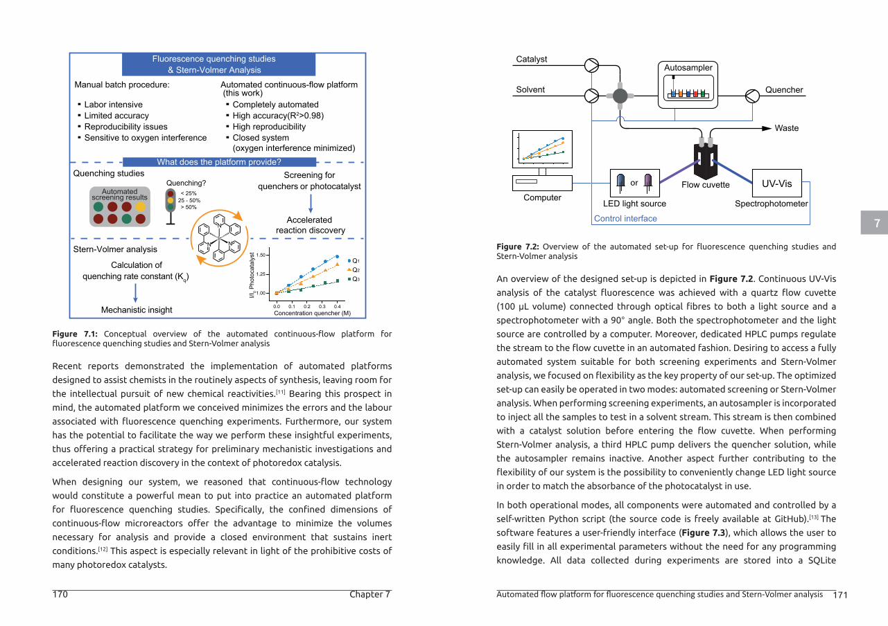
7
170 Chapter 7 Automated flow platform for fluorescence quenching studies and Stern-Volmer analysis 171
Figure 7.1: Conceptual overview of the automated continuous-flow platform for fluorescence quenching studies and Stern-Volmer analysis
Recent reports demonstrated the implementation of automated platforms
designed to assist chemists in the routinely aspects of synthesis, leaving room for
the intellectual pursuit of new chemical reactivities.[11] Bearing this prospect in
mind, the automated platform we conceived minimizes the errors and the labour
associated with fluorescence quenching experiments. Furthermore, our system
has the potential to facilitate the way we perform these insightful experiments,
thus offering a practical strategy for preliminary mechanistic investigations and
accelerated reaction discovery in the context of photoredox catalysis.
When designing our system, we reasoned that continuous-flow technology
would constitute a powerful mean to put into practice an automated platform
for fluorescence quenching studies. Specifically, the confined dimensions of
continuous-flow microreactors offer the advantage to minimize the volumes
necessary for analysis and provide a closed environment that sustains inert
conditions.[12] This aspect is especially relevant in light of the prohibitive costs of
many photoredox catalysts.
Figure 7.2: Overview of the automated set-up for fluorescence quenching studies and Stern-Volmer analysis
An overview of the designed set-up is depicted in Figure 7.2. Continuous UV-Vis
analysis of the catalyst fluorescence was achieved with a quartz flow cuvette
(100 μL volume) connected through optical fibres to both a light source and a
spectrophotometer with a 90° angle. Both the spectrophotometer and the light
source are controlled by a computer. Moreover, dedicated HPLC pumps regulate
the stream to the flow cuvette in an automated fashion. Desiring to access a fully
automated system suitable for both screening experiments and Stern-Volmer
analysis, we focused on flexibility as the key property of our set-up. The optimized
set-up can easily be operated in two modes: automated screening or Stern-Volmer
analysis. When performing screening experiments, an autosampler is incorporated
to inject all the samples to test in a solvent stream. This stream is then combined
with a catalyst solution before entering the flow cuvette. When performing
Stern-Volmer analysis, a third HPLC pump delivers the quencher solution, while
the autosampler remains inactive. Another aspect further contributing to the
flexibility of our system is the possibility to conveniently change LED light source
in order to match the absorbance of the photocatalyst in use.
In both operational modes, all components were automated and controlled by a
self-written Python script (the source code is freely available at GitHub).[13] The
software features a user-friendly interface (Figure 7.3), which allows the user to
easily fill in all experimental parameters without the need for any programming
knowledge. All data collected during experiments are stored into a SQLite
What does the platform provide?
NIr
N
N
Calculation ofquenching rate constant (Kq)
Mechanistic insight
Quenching studies
Stern-Volmer analysis
AutomatedQuenching?
< 25%25 - 50%> 50%
screening results
Screening for quenchers or photocatalyst
Accelerated reaction discovery
Labor intensiveLimited accuracy Reproducibility issuesSensitive to oxygen interference
Manual batch procedure: Automated continuous-flow platform (this work)
Completely automated High accuracy(R2>0.98)High reproducibilityClosed system(oxygen interference minimized)
0.0 0.1 0.2 0.3 0.4
1.00
1.25
1.50I/I
0 Pho
toca
taly
st
Concentration quencher (M)
Q1
Q2
Q3
Fluorescence quenching studies & Stern-Volmer Analysis
LED light source
Autosampler
or Flow cuvette
SpectrophotometerComputer
Waste
Catalyst
Solvent Quencher
UV-Vis
Control interface
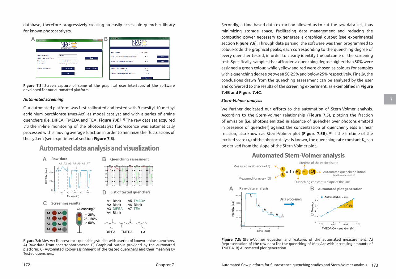
7
172 Chapter 7 Automated flow platform for fluorescence quenching studies and Stern-Volmer analysis 173
database, therefore progressively creating an easily accessible quencher library
for known photocatalysts.
Figure 7.3: Screen capture of some of the graphical user interfaces of the software developed for our automated platform.
Automated screening
Our automated platform was first calibrated and tested with 9-mesityl-10-methyl
acridinium perchlorate (Mes-Acr) as model catalyst and with a series of amine
quenchers (i.e. DIPEA, TMEDA and TEA, Figure 7.4).[14] The raw data set acquired
via the in-line monitoring of the photocatalyst fluorescence was automatically
processed with a moving average function in order to minimize the fluctuations of
the system (see experimental section Figure 7.6).
Figure 7.4: Mes-Acr fluorescence quenching studies with a series of known amine quenchers. A) Raw-data from spectrophotometer. B) Graphical output provided by the automated platform. C) Automated colour-assignment of the tested quenchers and their meaning D) Tested quenchers.
Secondly, a time-based data extraction allowed us to cut the raw data set, thus
minimizing storage space, facilitating data management and reducing the
computing power necessary to generate a graphical output (see experimental
section Figure 7.6). Through data parsing, the software was then programmed to
colour-code the graphical peaks, each corresponding to the quenching degree of
every quencher tested, in order to clearly identify the outcome of the screening
test. Specifically, samples that afforded a quenching degree higher than 50% were
assigned a green colour, while yellow and red were chosen as colours for samples
with a quenching degree between 50-25% and below 25% respectively. Finally, the
conclusions drawn from the quenching assessment can be analysed by the user
and converted to the results of the screening experiment, as exemplified in Figure
7.4B and Figure 7.4C.
Stern-Volmer analysis
We further dedicated our efforts to the automation of Stern-Volmer analysis.
According to the Stern-Volmer relationship (Figure 7.5), plotting the fraction
of emission (i.e. photons emitted in absence of quencher over photons emitted
in presence of quencher) against the concentration of quencher yields a linear
relation, also known as Stern-Volmer plot (Figure 7.5B).[3b] If the lifetime of the
excited state (τ0) of the photocatalyst is known, the quenching rate constant Kq can
be derived from the slope of the Stern-Volmer plot.
Figure 7.5: Stern-Volmer equation and features of the automated measurement. A) Representation of the raw data for the quenching of Mes-Acr with increasing amounts of TMEDA. B) Automated plot generation.
A B
A1
A2
A3
A4
A5
A6
A7
A8
Quenching assessmentBA Raw-data
Automated data analysis and visualization
D
CQuenching?
< 25%25 - 50%> 50%
A1 A2 A3 A4 A5 A6 A7
Screening results
List of tested quenchers
A1 BlankA2 BlankA3 DIPEAA4 Blank
A5 TMEDAA6 BlankA7 TEA
N NN
N
DIPEA TMEDA TEA
A1 A2 A3 A4 A5 A6 A7
A Automated plot generationBRaw-data analysis
Automated Stern-Volmer analysis
Data processing
Automated (R2 = 0.99)
Measured for every [Q]
Measured in absence of Q
Automated quencher dilution(via �ow rate control)
Quenching constant = slope of the line
Lifetime of the excited state
0.00 0.01 0.02 0.030
1
2
3
4
I 0/I M
es-A
cr
TMEDA Concentration (M)0 5 10 15 20
0
50000
100000
150000
200000
Inte
nsity
(a.u
.)Time (min)
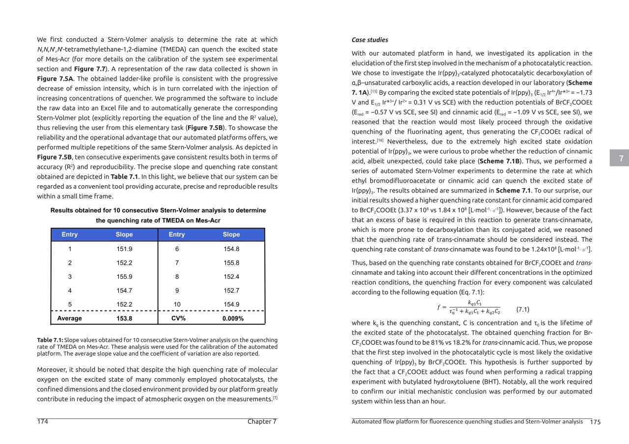
7
174 Chapter 7 Automated flow platform for fluorescence quenching studies and Stern-Volmer analysis 175
We first conducted a Stern-Volmer analysis to determine the rate at which
N,N,N′,N′-tetramethylethane-1,2-diamine (TMEDA) can quench the excited state
of Mes-Acr (for more details on the calibration of the system see experimental
section and Figure 7.7). A representation of the raw data collected is shown in
Figure 7.5A. The obtained ladder-like profile is consistent with the progressive
decrease of emission intensity, which is in turn correlated with the injection of
increasing concentrations of quencher. We programmed the software to include
the raw data into an Excel file and to automatically generate the corresponding
Stern-Volmer plot (explicitly reporting the equation of the line and the R2 value),
thus relieving the user from this elementary task (Figure 7.5B). To showcase the
reliability and the operational advantage that our automated platforms offers, we
performed multiple repetitions of the same Stern-Volmer analysis. As depicted in
Figure 7.5B, ten consecutive experiments gave consistent results both in terms of
accuracy (R2) and reproducibility. The precise slope and quenching rate constant
obtained are depicted in Table 7.1. In this light, we believe that our system can be
regarded as a convenient tool providing accurate, precise and reproducible results
within a small time frame.
Table 7.1: Slope values obtained for 10 consecutive Stern-Volmer analysis on the quenching rate of TMEDA on Mes-Acr. These analysis were used for the calibration of the automated platform. The average slope value and the coefficient of variation are also reported.
Moreover, it should be noted that despite the high quenching rate of molecular
oxygen on the excited state of many commonly employed photocatalysts, the
confined dimensions and the closed environment provided by our platform greatly
contribute in reducing the impact of atmospheric oxygen on the measurements.[7]
Case studies
With our automated platform in hand, we investigated its application in the
elucidation of the first step involved in the mechanism of a photocatalytic reaction.
We chose to investigate the Ir(ppy)3-catalyzed photocatalytic decarboxylation of
α,β–unsaturated carboxylic acids, a reaction developed in our laboratory (Scheme
7. 1A).[15] By comparing the excited state potentials of Ir(ppy)3 (E1/2 Ir4+/Ir*3+ = −1.73
V and E1/2 Ir*3+/ Ir2+ = 0.31 V vs SCE) with the reduction potentials of BrCF2COOEt
(Ered = −0.57 V vs SCE, see SI) and cinnamic acid (Ered = −1.09 V vs SCE, see SI), we
reasoned that the reaction would most likely proceed through the oxidative
quenching of the fluorinating agent, thus generating the CF2COOEt radical of
interest.[16] Nevertheless, due to the extremely high excited state oxidation
potential of Ir(ppy)3, we were curious to probe whether the reduction of cinnamic
acid, albeit unexpected, could take place (Scheme 7.1B). Thus, we performed a
series of automated Stern-Volmer experiments to determine the rate at which
ethyl bromodifluoroacetate or cinnamic acid can quench the excited state of
Ir(ppy)3. The results obtained are summarized in Scheme 7.1. To our surprise, our
initial results showed a higher quenching rate constant for cinnamic acid compared
to BrCF2COOEt (3.37 x 10⁸ vs 1.84 x 10⁸ [L·mol-1·s-1]). However, because of the fact
that an excess of base is required in this reaction to generate trans-cinnamate,
which is more prone to decarboxylation than its conjugated acid, we reasoned
that the quenching rate of trans-cinnamate should be considered instead. The
quenching rate constant of trans-cinnamate was found to be 1.24x10⁸ [L·mol-1·s-1].
Thus, based on the quenching rate constants obtained for BrCF2COOEt and trans-
cinnamate and taking into account their different concentrations in the optimized
reaction conditions, the quenching fraction for every component was calculated
according to the following equation (Eq. 7.1):
(7.1)
where kq is the quenching constant, C is concentration and τ0 is the lifetime of
the excited state of the photocatalyst. The obtained quenching fraction for Br-
CF2COOEt was found to be 81% vs 18.2% for trans-cinnamic acid. Thus, we propose
that the first step involved in the photocatalytic cycle is most likely the oxidative
quenching of Ir(ppy)3 by BrCF2COOEt. This hypothesis is further supported by
the fact that a CF2COOEt adduct was found when performing a radical trapping
experiment with butylated hydroxytoluene (BHT). Notably, all the work required
to confirm our initial mechanistic conclusion was performed by our automated
system within less than an hour.
Entry Slope
1
2
3
151.9
152.2
155.9
4 154.7
5 152.2
Entry Slope
6 154.8
7 155.8
8 152.4
9 152.7
10 154.9
Average 153.8 CV% 0.009%
Results obtained for 10 consecutive Stern-Volmer analysis to determinethe quenching rate of TMEDA on Mes-Acr
𝑓𝑓𝑓𝑓 = 𝑘𝑘𝑘𝑘𝑞𝑞𝑞𝑞1𝐶𝐶𝐶𝐶1
𝜏𝜏𝜏𝜏0−1 + 𝑘𝑘𝑘𝑘𝑞𝑞𝑞𝑞1𝐶𝐶𝐶𝐶1 + 𝑘𝑘𝑘𝑘𝑞𝑞𝑞𝑞2𝐶𝐶𝐶𝐶2
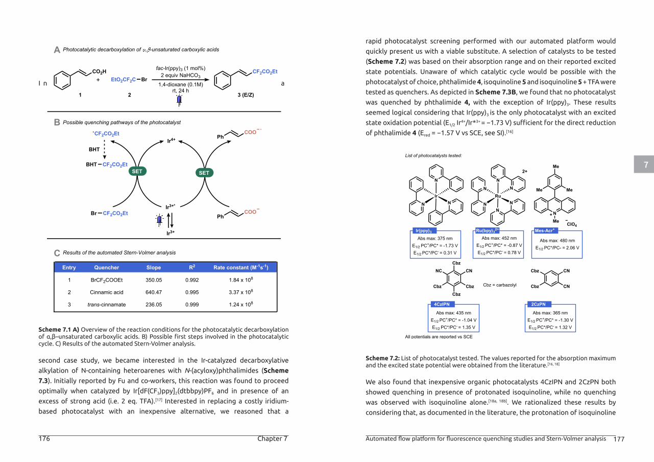
7
176 Chapter 7 Automated flow platform for fluorescence quenching studies and Stern-Volmer analysis 177
I n a
Scheme 7.1 A) Overview of the reaction conditions for the photocatalytic decarboxylation of α,β–unsaturated carboxylic acids. B) Possible first steps involved in the photocatalytic cycle. C) Results of the automated Stern-Volmer analysis.
second case study, we became interested in the Ir-catalyzed decarboxylative
alkylation of N-containing heteroarenes with N-(acyloxy)phthalimides (Scheme
7.3). Initially reported by Fu and co-workers, this reaction was found to proceed
optimally when catalyzed by Ir[dF(CF3)ppy]2(dtbbpy)PF6 and in presence of an
excess of strong acid (i.e. 2 eq. TFA).[17] Interested in replacing a costly iridium-
based photocatalyst with an inexpensive alternative, we reasoned that a
rapid photocatalyst screening performed with our automated platform would
quickly present us with a viable substitute. A selection of catalysts to be tested
(Scheme 7.2) was based on their absorption range and on their reported excited
state potentials. Unaware of which catalytic cycle would be possible with the
photocatalyst of choice, phthalimide 4, isoquinoline 5 and isoquinoline 5 + TFA were
tested as quenchers. As depicted in Scheme 7.3B, we found that no photocatalyst
was quenched by phthalimide 4, with the exception of Ir(ppy)3. These results
seemed logical considering that Ir(ppy)3 is the only photocatalyst with an excited
state oxidation potential (E1/2 Ir4+/Ir*3+ = −1.73 V) sufficient for the direct reduction
of phthalimide 4 (Ered = −1.57 V vs SCE, see SI).[16]
Scheme 7.2: List of photocatalyst tested. The values reported for the absorption maximum and the excited state potential were obtained from the literature.[16, 18]
We also found that inexpensive organic photocatalysts 4CzIPN and 2CzPN both
showed quenching in presence of protonated isoquinoline, while no quenching
was observed with isoquinoline alone.[18a, 18b]. We rationalized these results by
considering that, as documented in the literature, the protonation of isoquinoline
Photocatalytic decarboxylation of , -unsaturated carboxylic acids
Possible quenching pathways of the photocatalyst
Ph
Ir3+
COO
Ir3+*
Ir4+
SET SET
Br CF2CO2Et
CF2CO2Et
PhCOO
CO2H CF2CO2Etfac-Ir(ppy)3 (1 mol%)2 equiv NaHCO3EtO2CF2C Br1,4-dioxane (0.1M)
rt, 24 h
+
1 2 3 (E/Z)
BHT
BHT CF2CO2Et
Results of the automated Stern-Volmer analysis
Entry Quencher Slope Rate constant (M-1s-1)
1
2
3
R2
BrCF2COOEt 350.05 0.992 1.84 x 10⁸
640.47 0.995 3.37 x 10⁸
trans-cinnamate 236.05 0.999 1.24 x 10⁸
Cinnamic acid
A
C
B
List of photocatalysts tested:
Abs max: 375 nmE1/2 PC+/PC* = -1.73 VE1/2 PC*/PC- = 0.31 V
Abs max: 480 nmE1/2 PC*/PC- = 2.06 V
N
N
RuN
N
N
N
N
IrN
N
2+
NMe ClO4
Me
MeMe
Cbz
CbzCbz
Cbz
CNNC
Abs max: 435 nmE1/2 PC+/PC* = -1.04 VE1/2 PC*/PC- = 1.35 V
Cbz
CN
Cbz = carbazolyl
Abs max: 365 nmE1/2 PC+/PC* = -1.30 VE1/2 PC*/PC- = 1.32 V
Cbz
CN
All potentials are reported vs SCE
Abs max: 452 nmE1/2 PC+/PC* = -0.87 VE1/2 PC*/PC- = 0.78 V
Ir(ppy)3 Ru(bpy)32+ Mes-Acr+
4CzIPN 2CzPN
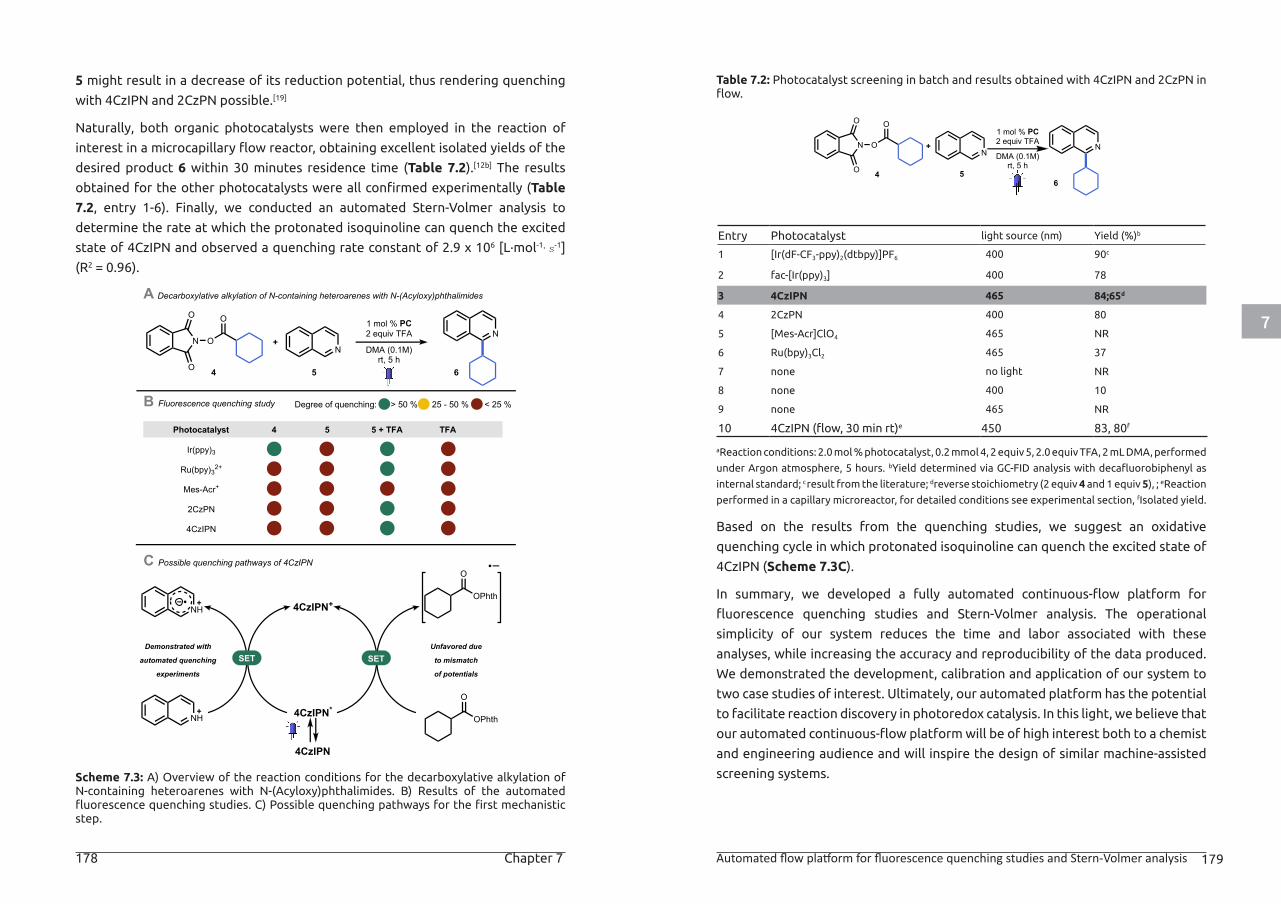
7
178 Chapter 7 Automated flow platform for fluorescence quenching studies and Stern-Volmer analysis 179
5 might result in a decrease of its reduction potential, thus rendering quenching
with 4CzIPN and 2CzPN possible.[19]
Naturally, both organic photocatalysts were then employed in the reaction of
interest in a microcapillary flow reactor, obtaining excellent isolated yields of the
desired product 6 within 30 minutes residence time (Table 7.2).[12b] The results
obtained for the other photocatalysts were all confirmed experimentally (Table
7.2, entry 1-6). Finally, we conducted an automated Stern-Volmer analysis to
determine the rate at which the protonated isoquinoline can quench the excited
state of 4CzIPN and observed a quenching rate constant of 2.9 x 10⁶ [L·mol-1·s-1]
(R2 = 0.96).
Scheme 7.3: A) Overview of the reaction conditions for the decarboxylative alkylation of N-containing heteroarenes with N-(Acyloxy)phthalimides. B) Results of the automated fluorescence quenching studies. C) Possible quenching pathways for the first mechanistic step.
Table 7.2: Photocatalyst screening in batch and results obtained with 4CzIPN and 2CzPN in flow.
Entry Photocatalyst light source (nm) Yield (%)b
1 [Ir(dF-CF3-ppy)2(dtbpy)]PF6 400 90c
2 fac-[Ir(ppy)3] 400 78
3 4CzIPN 465 84;65d
4 2CzPN 400 80
5 [Mes-Acr]ClO4 465 NR
6 Ru(bpy)3Cl2 465 37
7 none no light NR
8 none 400 10
9 none 465 NR
10 4CzIPN (flow, 30 min rt)e 450 83, 80f
aReaction conditions: 2.0 mol % photocatalyst, 0.2 mmol 4, 2 equiv 5, 2.0 equiv TFA, 2 mL DMA, performed
under Argon atmosphere, 5 hours. bYield determined via GC-FID analysis with decafluorobiphenyl as
internal standard; c result from the literature; dreverse stoichiometry (2 equiv 4 and 1 equiv 5), ; eReaction
performed in a capillary microreactor, for detailed conditions see experimental section, fIsolated yield.
Based on the results from the quenching studies, we suggest an oxidative
quenching cycle in which protonated isoquinoline can quench the excited state of
4CzIPN (Scheme 7.3C).
In summary, we developed a fully automated continuous-flow platform for
fluorescence quenching studies and Stern-Volmer analysis. The operational
simplicity of our system reduces the time and labor associated with these
analyses, while increasing the accuracy and reproducibility of the data produced.
We demonstrated the development, calibration and application of our system to
two case studies of interest. Ultimately, our automated platform has the potential
to facilitate reaction discovery in photoredox catalysis. In this light, we believe that
our automated continuous-flow platform will be of high interest both to a chemist
and engineering audience and will inspire the design of similar machine-assisted
screening systems.
A Decarboxylative alkylation of N-containing heteroarenes with N-(Acyloxy)phthalimides
B Fluorescence quenching study
R2
4CzIPN
4CzIPN*
SET SET
1 mol % PC2 equiv TFA
DMA (0.1M)rt, 5 h
N
O
O
O
O
N
N+
C Possible quenching pathways of 4CzIPN
Photocatalyst 4 5 5 + TFA
4 5 6
TFA
Ir(ppy)3
Ru(bpy)32+
Mes-Acr+
4CzIPN
2CzPN
> 50 % 25 - 50 % < 25 %Degree of quenching:
4CzIPN+
OPhth
O
NH
NHOPhth
O
Unfavored due
to mismatch
of potentials
Demonstrated with
automated quenching
experiments
1 mol % PC2 equiv TFA
DMA (0.1M)rt, 5 h
N
O
O
O
O
NN+
4 56
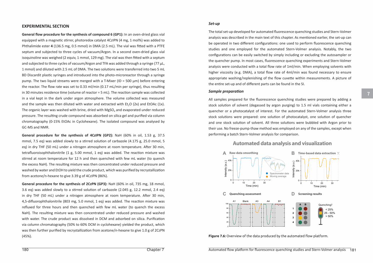
7
180 Chapter 7 Automated flow platform for fluorescence quenching studies and Stern-Volmer analysis 181
EXPERIMENTAL SECTION
General flow procedure for the synthesis of compound 6 (GP1): In an oven-dried glass vial equipped with a magnetic stirrer, photoredox catalyst 4CzIPN (4 mg, 1 mol%) was added to Phthalimide ester 4 (136.5 mg, 0.5 mmol) in DMA (2.5 mL). The vial was fitted with a PTFE septum and subjected to three cycles of vacuum/Argon. In a second oven-dried glass vial isoquinoline was weighed (2 equiv, 1 mmol, 129 mg). The vial was then fitted with a septum and subjected to three cycles of vacuum/Argon and TFA was added through a syringe (77 μL, 1 mmol) and diluted with 2.5 mL of DMA. The two solutions were transferred into two 5 mL BD Discardit plastic syringes and introduced into the photo-microreactor through a syringe pump. The two liquid streams were merged with a T-Mixer (ID = 500 μm) before entering the reactor. The flow rate was set to 0.33 ml/min (0.17 mL/min per syringe), thus resulting in 30 minutes residence time (volume of reactor = 5 mL). The reaction sample was collected in a vial kept in the dark under argon atmosphere. The volume collected was measured and the sample was then diluted with water and extracted with Et2O (2x) and EtOAc (1x). The organic layer was washed with brine, dried with MgSO4 and evaporated under reduced pressure. The resulting crude compound was absorbed on silica gel and purified via column chromatography (0-15% EtOAc in Cyclohexane). The isolated compound was analysed by GC-MS and NMR.
General procedure for the synthesis of 4CzIPN (GP2): NaH (60% in oil, 1.53 g, 37.5 mmol, 7.5 eq) was added slowly to a stirred solution of carbazole (4.175 g, 25.0 mmol, 5 eq) in dry THF (50 mL) under a nitrogen atmosphere at room temperature. After 30 min, tetrafluoroisophthalonitrile (1 g, 5.00 mmol, 1 eq) was added. The reaction mixture was stirred at room temperature for 12 h and then quenched with few mL water (to quench the excess NaH). The resulting mixture was then concentrated under reduced pressure and washed by water and EtOH to yield the crude product, which was purified by recrystallization from acetone/n-hexane to give 3.39 g of 4CzIPN (86%).
General procedure for the synthesis of 2CzPN (GP3): NaH (60% in oil, 735 mg, 18 mmol, 3.6 eq) was added slowly to a stirred solution of carbazole (2.045 g, 12.2 mmol, 2.4 eq) in dry THF (50 mL) under a nitrogen atmosphere at room temperature. After 30 min, 4,5-difluorophthalonitrile (803 mg, 5.0 mmol, 1 eq) was added. The reaction mixture was refluxed for three hours and then quenched with few mL water (to quench the excess NaH). The resulting mixture was then concentrated under reduced pressure and washed with water. The crude product was dissolved in DCM and adsorbed on silica. Purification via column chromatography (50% to 60% DCM in cyclohexane) yielded the product, which was then further purified by recrystallization from acetone/n-hexane to give 1.0 g of 2CzPN (45%).
Set-up
The total set-up developed for automated fluorescence quenching studies and Stern-Volmer analysis was described in the main text of this chapter. As mentioned earlier, the set-up can be operated in two different configurations: one used to perform fluorescence quenching studies and one employed for the automated Stern-Volmer analysis. Notably, the two configurations can be easily switched by simply including or excluding the autosampler or the quencher pump. In most cases, fluorescence quenching experiments and Stern-Volmer analysis were conducted with a total flow rate of 1ml/min. When employing solvents with higher viscosity (e.g. DMA), a total flow rate of 4ml/min was found necessary to ensure appropriate washing/replenishing of the flow cuvette within measurements. A picture of the entire set-up and of different parts can be found in the SI.
Sample preparation
All samples prepared for the fluorescence quenching studies were prepared by adding a stock solution of solvent (degassed by argon purging) to 1.5 ml vials containing either a quencher or a photocatalyst of interest. For the automated Stern-Volmer analysis three stock solutions were prepared: one solution of photocatalyst, one solution of quencher and one stock solution of solvent. All three solutions were bubbled with Argon prior to their use. No freeze-pump-thaw method was employed on any of the samples, except when performing a batch Stern-Volmer analysis for comparison.
Figure 7.6: Overview of the data produced by the automated flow platform.
0
20
40
60
80
100A1 Blank A3 A4 B1
A1
2
3
4
B
A
0 10 20 300
20k
40k
Inte
nsity
(a.u
.)
Time (min)
Time-based data extractionBRaw-data smoothing
Automated data analysis and visualization
DC Quenching assessment Screening results
Spectrometer dataMoving average
Quenching?
< 25%25 - 50%> 50%
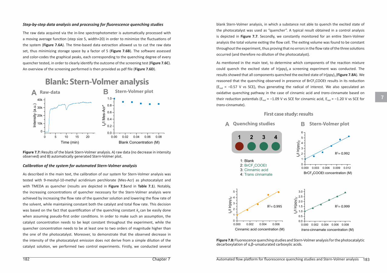
7
182 Chapter 7 Automated flow platform for fluorescence quenching studies and Stern-Volmer analysis 183
Step-by-step data analysis and processing for fluorescence quenching studies
The raw data acquired via the in-line spectrophotometer is automatically processed with a moving average function (step size 5, width=20) in order to minimize the fluctuations of the system (Figure 7.6A). The time-based data extraction allowed us to cut the raw data set, thus minimizing storage space by a factor of 5 (Figure 7.6B). The software assessed and color-codes the graphical peaks, each corresponding to the quenching degree of every quencher tested, in order to clearly identify the outcome of the screening test (Figure 7.6C). An overview of the screening performed is then provided as pdf file (Figure 7.6D).
Figure 7.7: Results of the blank Stern-Volmer analysis. A) raw data (no decrease in intensity observed) and B) automatically generated Stern-Volmer plot.
Calibration of the system for automated Stern-Volmer analysis
As described in the main text, the calibration of our system for Stern-Volmer analysis was tested with 9-mesityl-10-methyl acridinium perchlorate (Mes-Acr) as photocatalyst and with TMEDA as quencher (results are depicted in Figure 7.5and in Table 7.1). Notably, the increasing concentrations of quencher necessary for the Stern-Volmer analysis were achieved by increasing the flow rate of the quencher solution and lowering the flow rate of the solvent, while maintaining constant both the catalyst and total flow rate. This decision was based on the fact that quantification of the quenching constant kq can be easily done when assuming pseudo-first order conditions. In order to make such an assumption, the catalyst concentration needs to be kept constant throughout the experiment, while the quencher concentration needs to be at least one to two orders of magnitude higher than the one of the photocatalyst. Moreover, to demonstrate that the observed decrease in the intensity of the photocatalyst emission does not derive from a simple dilution of the catalyst solution, we performed two control experiments. Firstly, we conducted several
blank Stern-Volmer analysis, in which a substance not able to quench the excited state of the photocatalyst was used as “quencher”. A typical result obtained in a control analysis is depicted in Figure 7.7. Secondly, we constantly monitored for an entire Stern-Volmer analysis the total volume exiting the flow cell. The exiting volume was found to be constant throughout the experiment, thus proving that no errors in the flow rate of the three solutions occurred (and therefore no dilution of the photocatalyst).
As mentioned in the main text, to determine which components of the reaction mixture could quench the excited state of Ir(ppy)3 a screening experiment was conducted. The results showed that all components quenched the excited state of Ir(ppy)3 (Figure 7.8A). We reasoned that the quenching observed in presence of BrCF2COOEt results in its reduction (Ered = −0.57 V vs SCE), thus generating the radical of interest. We also speculated an oxidative quenching pathway in the case of cinnamic acid and trans-cinnamate based on their reduction potentials (Ered = −1.09 V vs SCE for cinnamic acid, Ered = −1.20 V vs SCE for trans-cinnamate).
Figure 7.8: Fluorescence quenching studies and Stern-Volmer analysis for the photocatalytic decarboxylation of α,β–unsaturated carboxylic acids.
A BRaw-data
Blank: Stern-Volmer analysisStern-Volmer plot
0.00 0.02 0.04 0.06 0.080.0
0.2
0.4
0.6
0.8
1.0I 0/
I Mes
-Acr
*
Blank Concentration (M)0 5 10 15 20
0
10k
20k
30k
40k
Inte
nsity
(a.u
.)
Time (min)
A BQuenching studies
First case study: results
Stern-Volmer plot
1 2 3 4
1: Blank2: BrCF2COOEt3: Cinnamic acid4: Trans cinnamate
R2= 0.999
0.000 0.002 0.004 0.0060
1
2
3
4
5
I 0/I I
r(ppy
) 3*
Cinnamic acid concentration (M)
R2= 0.995
0.000 0.003 0.006 0.009 0.0120
1
2
3
4
5
6
I 0/I I
r(ppy
) 3*
BrCF2COOEt concentration (M)
R2= 0.992
0.000 0.002 0.004 0.006 0.0080.0
0.5
1.0
1.5
2.0
2.5
3.0
I 0/I I
r(ppy
) 3*
trans-cinnamate concentration (M)
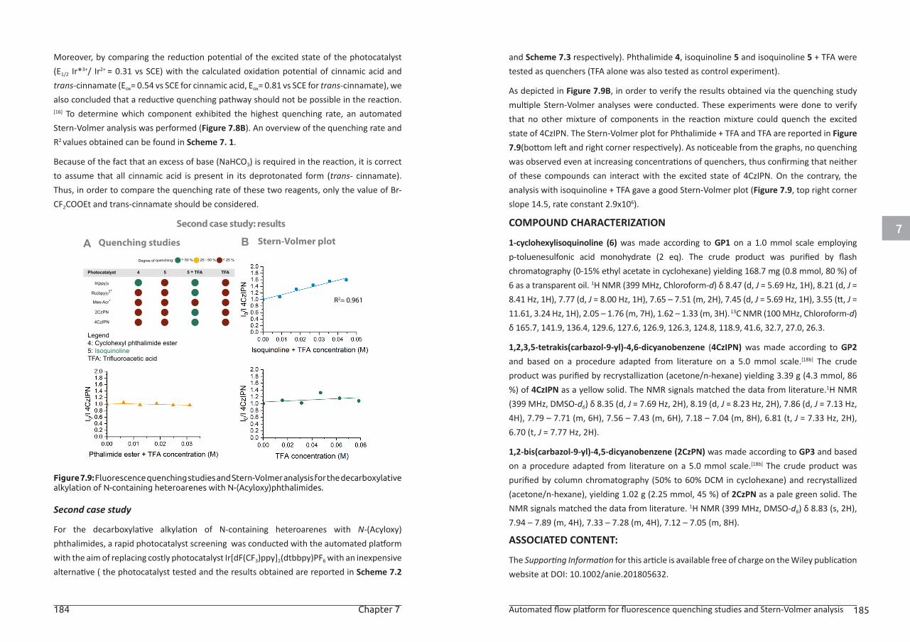
7
184 Chapter 7 Automated flow platform for fluorescence quenching studies and Stern-Volmer analysis 185
Moreover, by comparing the reduction potential of the excited state of the photocatalyst (E1/2 Ir*3+/ Ir2+ = 0.31 vs SCE) with the calculated oxidation potential of cinnamic acid and trans-cinnamate (Eox= 0.54 vs SCE for cinnamic acid, Eox= 0.81 vs SCE for trans-cinnamate), we also concluded that a reductive quenching pathway should not be possible in the reaction.[16] To determine which component exhibited the highest quenching rate, an automated Stern-Volmer analysis was performed (Figure 7.8B). An overview of the quenching rate and R2 values obtained can be found in Scheme 7. 1.
Because of the fact that an excess of base (NaHCO3) is required in the reaction, it is correct to assume that all cinnamic acid is present in its deprotonated form (trans- cinnamate). Thus, in order to compare the quenching rate of these two reagents, only the value of Br-CF2COOEt and trans-cinnamate should be considered.
Figure 7.9: Fluorescence quenching studies and Stern-Volmer analysis for the decarboxylative alkylation of N-containing heteroarenes with N-(Acyloxy)phthalimides.
Second case study
For the decarboxylative alkylation of N-containing heteroarenes with N-(Acyloxy)phthalimides, a rapid photocatalyst screening was conducted with the automated platform with the aim of replacing costly photocatalyst Ir[dF(CF3)ppy]2(dtbbpy)PF6 with an inexpensive alternative ( the photocatalyst tested and the results obtained are reported in Scheme 7.2
and Scheme 7.3 respectively). Phthalimide 4, isoquinoline 5 and isoquinoline 5 + TFA were tested as quenchers (TFA alone was also tested as control experiment).
As depicted in Figure 7.9B, in order to verify the results obtained via the quenching study multiple Stern-Volmer analyses were conducted. These experiments were done to verify that no other mixture of components in the reaction mixture could quench the excited state of 4CzIPN. The Stern-Volmer plot for Phthalimide + TFA and TFA are reported in Figure 7.9(bottom left and right corner respectively). As noticeable from the graphs, no quenching was observed even at increasing concentrations of quenchers, thus confirming that neither of these compounds can interact with the excited state of 4CzIPN. On the contrary, the analysis with isoquinoline + TFA gave a good Stern-Volmer plot (Figure 7.9, top right corner slope 14.5, rate constant 2.9x10⁶).
COMPOUND CHARACTERIZATION
1-cyclohexylisoquinoline (6) was made according to GP1 on a 1.0 mmol scale employing p-toluenesulfonic acid monohydrate (2 eq). The crude product was purified by flash chromatography (0-15% ethyl acetate in cyclohexane) yielding 168.7 mg (0.8 mmol, 80 %) of 6 as a transparent oil. 1H NMR (399 MHz, Chloroform-d) δ 8.47 (d, J = 5.69 Hz, 1H), 8.21 (d, J = 8.41 Hz, 1H), 7.77 (d, J = 8.00 Hz, 1H), 7.65 – 7.51 (m, 2H), 7.45 (d, J = 5.69 Hz, 1H), 3.55 (tt, J = 11.61, 3.24 Hz, 1H), 2.05 – 1.76 (m, 7H), 1.62 – 1.33 (m, 3H). 13C NMR (100 MHz, Chloroform-d) δ 165.7, 141.9, 136.4, 129.6, 127.6, 126.9, 126.3, 124.8, 118.9, 41.6, 32.7, 27.0, 26.3.
1,2,3,5-tetrakis(carbazol-9-yl)-4,6-dicyanobenzene (4CzIPN) was made according to GP2 and based on a procedure adapted from literature on a 5.0 mmol scale.[18b] The crude product was purified by recrystallization (acetone/n-hexane) yielding 3.39 g (4.3 mmol, 86 %) of 4CzIPN as a yellow solid. The NMR signals matched the data from literature.1H NMR (399 MHz, DMSO-d6) δ 8.35 (d, J = 7.69 Hz, 2H), 8.19 (d, J = 8.23 Hz, 2H), 7.86 (d, J = 7.13 Hz, 4H), 7.79 – 7.71 (m, 6H), 7.56 – 7.43 (m, 6H), 7.18 – 7.04 (m, 8H), 6.81 (t, J = 7.33 Hz, 2H), 6.70 (t, J = 7.77 Hz, 2H).
1,2-bis(carbazol-9-yl)-4,5-dicyanobenzene (2CzPN) was made according to GP3 and based on a procedure adapted from literature on a 5.0 mmol scale.[18b] The crude product was purified by column chromatography (50% to 60% DCM in cyclohexane) and recrystallized (acetone/n-hexane), yielding 1.02 g (2.25 mmol, 45 %) of 2CzPN as a pale green solid. The NMR signals matched the data from literature. 1H NMR (399 MHz, DMSO-d6) δ 8.83 (s, 2H), 7.94 – 7.89 (m, 4H), 7.33 – 7.28 (m, 4H), 7.12 – 7.05 (m, 8H).
ASSOCIATED CONTENT:
The Supporting Information for this article is available free of charge on the Wiley publication website at DOI: 10.1002/anie.201805632.
A BQuenching studies
Second case study: results
Stern-Volmer plot
Legend4: Cyclohexyl phthalimide ester5: IsoquinolineTFA: Trifluoroacetic acid
Photocatalyst 4 5 5 + TFA TFA
Ir(ppy)3
Ru(bpy)32+
Mes-Acr+
4CzIPN
2CzPN
> 50 % 25 - 50 % < 25 %Degree of quenching:
R2= 0.961
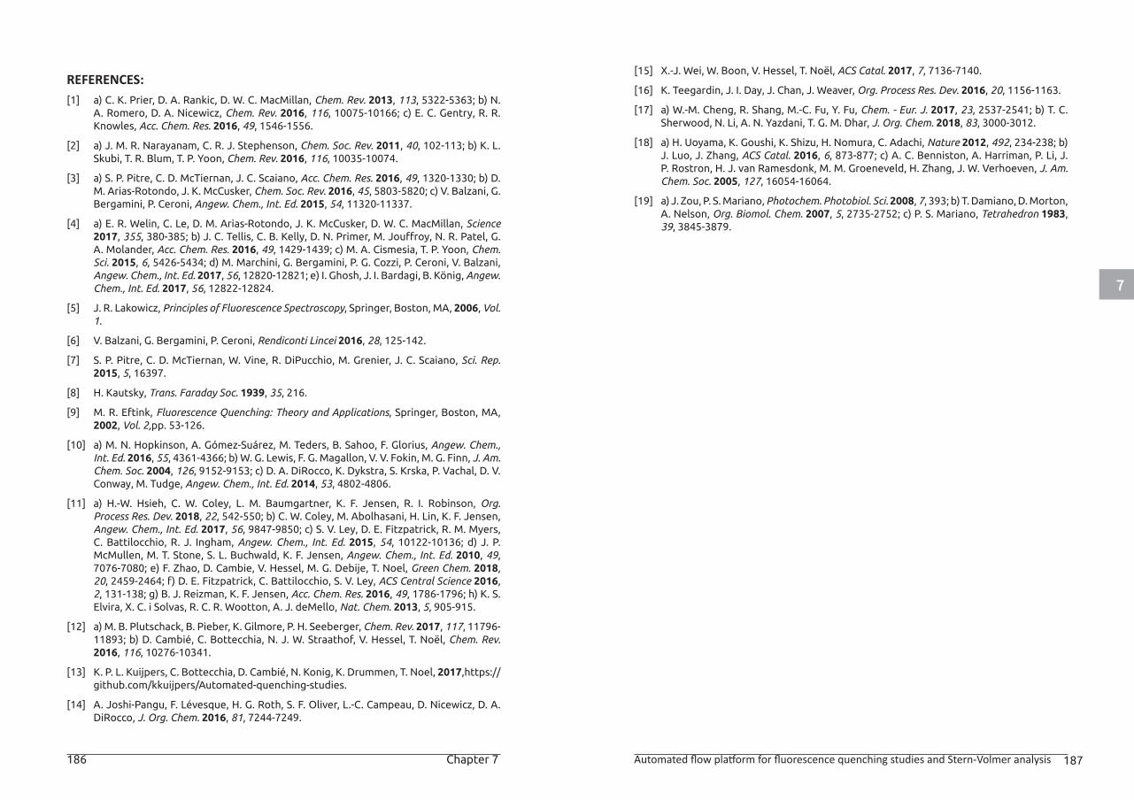
7
186 Chapter 7 Automated flow platform for fluorescence quenching studies and Stern-Volmer analysis 187
REFERENCES:[1] a) C. K. Prier, D. A. Rankic, D. W. C. MacMillan, Chem. Rev. 2013, 113, 5322-5363; b) N.
A. Romero, D. A. Nicewicz, Chem. Rev. 2016, 116, 10075-10166; c) E. C. Gentry, R. R. Knowles, Acc. Chem. Res. 2016, 49, 1546-1556.
[2] a) J. M. R. Narayanam, C. R. J. Stephenson, Chem. Soc. Rev. 2011, 40, 102-113; b) K. L. Skubi, T. R. Blum, T. P. Yoon, Chem. Rev. 2016, 116, 10035-10074.
[3] a) S. P. Pitre, C. D. McTiernan, J. C. Scaiano, Acc. Chem. Res. 2016, 49, 1320-1330; b) D. M. Arias-Rotondo, J. K. McCusker, Chem. Soc. Rev. 2016, 45, 5803-5820; c) V. Balzani, G. Bergamini, P. Ceroni, Angew. Chem., Int. Ed. 2015, 54, 11320-11337.
[4] a) E. R. Welin, C. Le, D. M. Arias-Rotondo, J. K. McCusker, D. W. C. MacMillan, Science 2017, 355, 380-385; b) J. C. Tellis, C. B. Kelly, D. N. Primer, M. Jouffroy, N. R. Patel, G. A. Molander, Acc. Chem. Res. 2016, 49, 1429-1439; c) M. A. Cismesia, T. P. Yoon, Chem. Sci. 2015, 6, 5426-5434; d) M. Marchini, G. Bergamini, P. G. Cozzi, P. Ceroni, V. Balzani, Angew. Chem., Int. Ed. 2017, 56, 12820-12821; e) I. Ghosh, J. I. Bardagi, B. König, Angew. Chem., Int. Ed. 2017, 56, 12822-12824.
[5] J. R. Lakowicz, Principles of Fluorescence Spectroscopy, Springer, Boston, MA, 2006, Vol. 1.
[6] V. Balzani, G. Bergamini, P. Ceroni, Rendiconti Lincei 2016, 28, 125-142.
[7] S. P. Pitre, C. D. McTiernan, W. Vine, R. DiPucchio, M. Grenier, J. C. Scaiano, Sci. Rep. 2015, 5, 16397.
[8] H. Kautsky, Trans. Faraday Soc. 1939, 35, 216.
[9] M. R. Eftink, Fluorescence Quenching: Theory and Applications, Springer, Boston, MA, 2002, Vol. 2,pp. 53-126.
[10] a) M. N. Hopkinson, A. Gómez-Suárez, M. Teders, B. Sahoo, F. Glorius, Angew. Chem., Int. Ed. 2016, 55, 4361-4366; b) W. G. Lewis, F. G. Magallon, V. V. Fokin, M. G. Finn, J. Am. Chem. Soc. 2004, 126, 9152-9153; c) D. A. DiRocco, K. Dykstra, S. Krska, P. Vachal, D. V. Conway, M. Tudge, Angew. Chem., Int. Ed. 2014, 53, 4802-4806.
[11] a) H.-W. Hsieh, C. W. Coley, L. M. Baumgartner, K. F. Jensen, R. I. Robinson, Org. Process Res. Dev. 2018, 22, 542-550; b) C. W. Coley, M. Abolhasani, H. Lin, K. F. Jensen, Angew. Chem., Int. Ed. 2017, 56, 9847-9850; c) S. V. Ley, D. E. Fitzpatrick, R. M. Myers, C. Battilocchio, R. J. Ingham, Angew. Chem., Int. Ed. 2015, 54, 10122-10136; d) J. P. McMullen, M. T. Stone, S. L. Buchwald, K. F. Jensen, Angew. Chem., Int. Ed. 2010, 49, 7076-7080; e) F. Zhao, D. Cambie, V. Hessel, M. G. Debije, T. Noel, Green Chem. 2018, 20, 2459-2464; f) D. E. Fitzpatrick, C. Battilocchio, S. V. Ley, ACS Central Science 2016, 2, 131-138; g) B. J. Reizman, K. F. Jensen, Acc. Chem. Res. 2016, 49, 1786-1796; h) K. S. Elvira, X. C. i Solvas, R. C. R. Wootton, A. J. deMello, Nat. Chem. 2013, 5, 905-915.
[12] a) M. B. Plutschack, B. Pieber, K. Gilmore, P. H. Seeberger, Chem. Rev. 2017, 117, 11796-11893; b) D. Cambié, C. Bottecchia, N. J. W. Straathof, V. Hessel, T. Noël, Chem. Rev. 2016, 116, 10276-10341.
[13] K. P. L. Kuijpers, C. Bottecchia, D. Cambié, N. Konig, K. Drummen, T. Noel, 2017,https://github.com/kkuijpers/Automated-quenching-studies.
[14] A. Joshi-Pangu, F. Lévesque, H. G. Roth, S. F. Oliver, L.-C. Campeau, D. Nicewicz, D. A. DiRocco, J. Org. Chem. 2016, 81, 7244-7249.
[15] X.-J. Wei, W. Boon, V. Hessel, T. Noël, ACS Catal. 2017, 7, 7136-7140.
[16] K. Teegardin, J. I. Day, J. Chan, J. Weaver, Org. Process Res. Dev. 2016, 20, 1156-1163.
[17] a) W.-M. Cheng, R. Shang, M.-C. Fu, Y. Fu, Chem. - Eur. J. 2017, 23, 2537-2541; b) T. C. Sherwood, N. Li, A. N. Yazdani, T. G. M. Dhar, J. Org. Chem. 2018, 83, 3000-3012.
[18] a) H. Uoyama, K. Goushi, K. Shizu, H. Nomura, C. Adachi, Nature 2012, 492, 234-238; b) J. Luo, J. Zhang, ACS Catal. 2016, 6, 873-877; c) A. C. Benniston, A. Harriman, P. Li, J. P. Rostron, H. J. van Ramesdonk, M. M. Groeneveld, H. Zhang, J. W. Verhoeven, J. Am. Chem. Soc. 2005, 127, 16054-16064.
[19] a) J. Zou, P. S. Mariano, Photochem. Photobiol. Sci. 2008, 7, 393; b) T. Damiano, D. Morton, A. Nelson, Org. Biomol. Chem. 2007, 5, 2735-2752; c) P. S. Mariano, Tetrahedron 1983, 39, 3845-3879.

Summary & Conclusions
List of abbreviations
List of publications
Acknowledgements
About the author
Summary & Conclusions 191
Summary & Conclusions
The research presented in this thesis focused on the implementation of visible-
light photoredox catalysis for bioactive molecule modification. Owing to the mild
reaction conditions (i.e. room temperature, use of visible light) and to the high
functional group tolerance, photoredox catalysis represents an ideal strategy
towards the chemoselective modification of this broad class of compounds. In
order to facilitate a uniform irradiation of the reaction medium and to accelerate
reaction kinetics, continuous-flow technology was chosen as the ideal platform to
enable these novel chemistries.
The work described in this dissertation can be divided in two main research lines.
Firstly, efforts towards the development of mild methodologies for cysteine
modification were discussed. Owing to the powerful combination of photoredox
catalysis with continuous flow technology, three strategies suitable for cysteine
modification at the single amino acid level or in peptide sequences were presented.
In Chapter 2 a fast and straightforward continuous-flow protocol for the visible
light-induced trifluoromethylation and perfluoroalkylation of cysteine was
described. By employing Ru(bpy)32+ as photocatalyst and either gaseous CF3I
or inexpensive perfluoroalkyl iodides as fluorinating agents, a broad array of
fluorinated cysteine derivatives and cysteine-containing dipeptides was obtained
in excellent yields within 5 minutes of reaction time. The implementation of a
continuous-flow microreactor afforded an enhanced gas-liquid mass transfer
between the two immiscible phases, while allowing a safe handling of gaseous
reactants. Mechanistic studies revealed that Ru(bpy)32+ undergoes a reductive
quenching cycle, but quantum yield measurements suggested that the presence
of concurrent radical chain mechanisms is likely. Further developments of this
work should focus on its application to more complex peptide substrates.
Specifically, more work is required to demonstrate site-selectivity towards
cysteine in sequences containing other amino acids that might interfere (e.g.
serine, lysine, histidine, and tryptophan). Moreover, a careful re-optimization of
reaction conditions (e.g. solvent, type of base, etc.) might facilitate the application
of the methodology to proteins as well. Finally, in the context of exploiting this
method for the preparation of large amounts of fluorinated cysteine derivatives, a
further improvement could be the creation of a two-step flow sequence allowing
the fluoroalkylation of cysteine followed by a deprotection step at the carboxylate
site. Such a telescoped two-step continuous-flow system would grant access to
192 Summary & Conclusions 193
gram scale of fluorinated cysteine derivatives ready to be employed in solid phase
peptide synthesis.
In Chapter 3, a mild and versatile protocol to accelerate the formation of
disulfide bonds was established. This visible light induced photocatalytic aerobic
oxidation of thiols was optimized with TiO2 as a heterogeneous photocatalyst.
The chemistry proved amenable to intramolecular S–S bond formation of cysteine
residues in complex peptides under biocompatible reaction conditions (buffer
solution, visible light, simple purification by filtration or centrifugation). Moreover,
a packed-bed reactor was prepared to allow the implementation of a continuous
protocol, resulting in an efficient and reliable scale-up of the reaction conditions.
A diverse set of symmetrical and unsymmetrical disulfides was obtained in good to
excellent yields within few minutes of reaction time. Future endeavours to improve
this methodology could be aimed at improving the reactor design. Specifically,
the disposition of the light source with the respect of the flow reactor could be
changed. Moreover, from a chemical point of view, more research on the use of
this methodology for the formation of unsymmetrical disulfides would be of high
interest. As example, the methodology could be further expanded to achieve
labeling of short peptides sequences with any linker/compound of interest.
Chapter 4 describes a mild and selective C-H arylation of cysteine. This
biocompatible, metal-free procedure relies on the use of aryldiazonium salts as
arylating agents and employs catalytic amounts of Eosin Y to afford the formation
of the desired aryl radicals. The batch method described was applied to the
chemoselective arylation of a model peptide in biocompatible reaction conditions
(room temperature, PBS buffer) within a short reaction time. Furthermore, the
implementation of a continuous-flow protocol afforded the in-situ formation of
diazonium salts, thus limiting the risks associated with their isolation. A broad
series of arylated cysteine derivatives and arylated cysteine-containing dipeptides
were prepared in flow within few seconds of residence time. Owing to the ease
of scalability, the flow protocol could be easily employed to obtain arylated
cysteine derivatives on gram scales, thus allowing the preparation of sufficient
quantities for automated solid phase peptide synthesis (SPPS). To improve the
relevance of this methodology, further work is required to establish whether
this arylation methodology might be suitable for cysteine arylation in longer
peptides and, possibly, in proteins. Towards this goal, a key point will be to
establish whether arylation of other amino acid residues (e.g. arylation at indole
moiety of Trp) will compete with the desired reaction. Moreover, similarly to what
discussed for Chapter 3, the methodology should be expanded to achieve labeling
of peptides with either linkers, drugs or biological probes. A potential hurdle to
be circumvented is the synthetic difficulty in preparing labels of interest with a
diazonium moiety. A possible solution would be to have the diazonium moiety as
part of a clickable linker, which could be attached to the label of interest after the
photocatalytic reaction at cysteine.
In the second part of the thesis, a parallel research line focused on the combination
of photoredox catalysis and microreactor technology to attempt to overcome some
of the drawbacks currently limiting the widespread use of photoredox catalysis
in the pharmaceutical industry. In particular, in Chapter 5, a continuous-flow
protocol for the trifluoromethylation of arenes, heteroarenes and benzofused
heterocycles was developed. Novel methodologies for the trifluoromethylation
of these compounds are highly demanded in the pharmaceutical industry, as the
introduction of fluorine atoms can greatly impact the electronic properties, acidity
and lipophilicity of drug candidates. The methodology relies on the use of solid,
shelf-stable CF3SO2Na as trifluoromethylating agent and of an iridium species as
photoredox catalyst. For the reaction scope, the focus was kept on substrates
of high value for drug discovery programs. Specifically, the applicability of the
methodology to nitrogen-containing heteroarenes/benzofused heterocycles
bearing halogen substituents was showcased. Moreover, process intensification in
a microflow reactor afforded reduced reaction times (30 minutes residence time)
and a high productivity. The main current limitation of this methodology resides
in the use of an expensive Ir-based photocatalyst. To improve the applicability
of this synthetic methods at the industrial scale, some measures could be taken.
Firstly, research into the use of an alternative, inexpensive organic catalysts (such
as those described in Chapter 6) could render the Ir species obsolete. Secondly, a
continuous-flow synthesis of the Ir photocatalyst could be designed starting from
relatively cheaper starting materials. Compared to a batch synthesis (typically
requiring high temperatures and long operation times for this class of transition-
metal complexes), the preparation of an Ir photocatalyst in flow could result in
increased yields and higher quality of the synthesized product thanks to the fine
control over the reaction temperature achievable in continuous systems.
As previously mentioned, one of the main obstacles currently preventing the
implementation of photoredox catalysis for the large scale production of fine
chemicals is the prohibitive cost and scarce availability of transition metal-based
photoredox catalysts (i.e. Ir and Ru polypyridyl complexes). Organic photocatalysts
often provide valuable and inexpensive alternatives to these complexes.
Therefore, the development of new classes of organic photoredox catalysts with
194 Summary & Conclusions 195
good redox properties, largely available or easily prepared in high yields would
contribute to further advance research in this field. In Chapter 6, the de novo
synthesis and characterization of a series of substituted bi-thiophene derivatives
as novel and inexpensive organic photocatalysts was described. DFT calculations
from our collaborators were used to predict a priori their absorption spectra
and redox potentials, which were then confirmed with experimental data. The
photocatalytic activity of this novel class of organic photoredox catalyst was then
demonstrated in two visible-light mediated strategies for the C–H functionalization
of heteroarenes. The activity of the tested compounds was comparable with that
of other commonly used organic or transition-metal photocatalysts. Starting
from the results obtained for this series of six derivatives, further research can
lead to the preparation of a second generation of improved bi-thiophene-based
photoredox catalyst. Specifically, the design of photocatalysts with different and
alternative substitution patterns, together with the use of DFT calculations to
predict their optical properties, can lead to photocatalyst with improved redox
potentials, different absorption spectra and increased chemical stability.
An important aspect in photoredox catalysis is the understanding of the
photophysical and photochemical aspects governing the interaction between the
excited state photocatalyst and the reaction substrates. Among the techniques
employed to determine the reactivity of the excited state photocatalyst,
fluorescence quenching studies and Stern-Volmer analysis are of high interest.
However, despite their relevance, these analyses are time consuming and often
air-sensitive. Desiring to facilitate, standardize and accelerate quenching screening
experiments and Stern-Volmer analysis, we developed a continuous-flow platform
able to perform these analyses in an automated fashion. As described in Chapter 7,
via in-line monitoring of the photocatalyst fluorescence, the interaction between
the excited state of a photocatalyst and an array of quenchers of interest can be
studied. Owing to the high level of automation, the system affords a time and
labor reduction, while granting access to accurate and reproducible data. The
potential of this platform to accelerate reaction discovery and to facilitate the
understanding of photocatalytic reaction mechanisms was showcased when it was
employed to rapidly select a suitable photocatalyst for a reaction of interest and
then to perform a Stern-Volmer analysis to elucidate the underlying mechanism
involved. Further improvement on this platform could result in an optimized set-
up capable of performing both fluorescence quenching studies and stern-Volmer
analysis at a higher pace. Such improvements could be achieved via minimization
of the dead volumes in the channels and by replacing the commercially available
flow cuvette with a specifically designed alternative.
In conclusion, the positive combination of photocatalysis and continuous-
flow technology resulted in the development of three strategies for cysteine
modification. The mild reaction conditions typical of photoredox catalysis,
together with the uniform irradiation of the reaction mixture enabled by microflow
reactors, proved to be especially suited to develop novel chemistries for amino
acid modification. At the beginning of this research, only few examples in the
literature showed the application of photocatalytic methodologies for biomolecule
modification, and examples on the implementation of continuous-flow reactors
for this purpose were yet to be reported. However, over the course of the last four
years an increased interest in the potential application of photoredox catalysis
in chemical biology lead to a plethora of publications elaborating on this matter.
As a result, photocatalytic approaches for the modification of cysteine, tyrosine,
methionine and tryptophan now exist. Despite these successful examples,
further improvements to ameliorate the applicability of these methodologies
beyond the single amino acid level and towards complex peptides and proteins
are paramount. In this context, an approach to obtain improved regioselectivity
in complex structures might be to target one or more residues with known redox
potential and match it with the redox potential of an appropriate photocatalyst.
Alternatively, taking example from the field of dual catalysis, approaches relying
on the use of organic photocatalysts and other catalytic systems could be designed.
The main advantage granted by a photoredox-transition metal dual catalytic
system lies in the possibility to generate radicals in mild reaction conditions and
in their subsequent addition to a transition-metal complex (i.e. single-electron
transmetalation). Through careful selection of both catalytic systems, improved
reaction conditions (e.g. faster kinetics, improved selectivity) could thus be
achieved.
Finally, the use of enabling technologies, such as microreactor technology and
automation protocols, might significantly facilitate the development of novel
photoredox methodologies for protein modification. For instance, they could
contribute in reducing the amount of materials needed for optimization while
allowing to easily control multiple reaction conditions.
196 List of Abbreviations 197
LIST OF ABBREVIATIONS
LIST OF ABBREVIATIONS USED IN THIS THESIS:[(Mes-Acr)ClO4] 9-Mesityl-10-methylacridinium perchlorate
2-MeTHF 2-methyl tetrahydrofuran
2CzPN 1,2-bis(carbazol-9-yl)-4,5-dicyanobenzene
4CzIPN 1,2,3,5-tetrakis(carbazol-9-yl)-4,6-dicyanobenzene
ACN Acetonitrile
AcOH Acetic acid
API Active pharmaceutical ingredient
BDE Bond dissociation energy
Boc tert-butyloxycarbonyl
BPR Back pressure regulator
CFL Compact fluorescent lamp
CF3SO2Cl Trifluoromethanesulfonyl chloride
CF3SO2Na Langlois reagent, Sodium trifluoromethanesulfinate
CHCl3 Chloroform
CTFR Copper tube flow reactor
CuAAC Copper-catalyzed alkyne-azide cycloaddition
CV Cyclic voltammetry
DCC N,N’-Dicyclohexylcarbodiimide
DCE Dichloroethane
DCM Dichloromethane
DFT Density functional theory
Dha Dehydroalanine
DIPEA N,N-Diisopropylethylamine
DLS Dynamic light scattering
DMAc Dimethylacetamide
DMF N,N-Dimethylformamide
DMSO Dimethyl sulfoxide
DPA 1,9-diphenylanthracene
DPV Differential pulse voltammetry
EtOAc Ethyl acetate
fac-[Ir(ppy)3] Tris[2-phenylpyridinato-C2,N]iridium(III)
FEP fluorinated ethylene propylene
GC-FID Gas chromatography flame ionization detector
GC-MS Gas chromatography-mass spectrometry
H2O Water
HOBt Hydroxybenzotriazole
HCl Hydrochloric acid
HPLC High pressure liquid chromatography
HRMS High resolution mass spectroscopy
ID Internal diameter
i-PrOH Isopropanol
IR Infrared
KOH Potassium hydroxide
LC-MS Liquid chromatography–mass spectrometry
LED Light emitting diode
MeCN Acetonitrile
MeOH Methanol
MgSO4 Magnesium sulfate
N-Ac-L-Cys-OMe N-(acetyl)-L-cysteine methyl ester
N-Boc-L-Cys -OMe N-(tert-Butoxycarbonyl)-L-cysteine methyl ester
Na2SO4 Sodium sulfate
NaHCO3 Sodium hydrogen carbonate
NaOH Sodium hydroxide
n-BuOH n-Butanol
NH3 Ammonia
(NH4)2S2O8 Ammonium persulfate
NMR Nuclear magnetic resonance
OFET Organic field-effect transistor
PBS Phosphate-buffered saline
PE Petrol Ether
PEEK Polyether ether ketone
PET Positron Emission Tomography
PFA Perfluoroalkoxy alkane
Ph3N Triphenyl amine
PTFE Polytetrafluoroethylene
p-TsOH p-toluenesulfonic acid
Ru(bpy)3Cl2 Tris(bipyridine)ruthenium(II) chloride
SAR Structure-activity relationship
SCE Saturated calomel electrode
SEM Scanning electron microscopy
SET Single electron transfer
SI Supporting information
List of Publications 199198
SPPS Solid phase peptide synthesis
tBuONO tert-butyl nitrite
tBuOOH Tert-butyl hydroperoxide
TD-DFT Time-dependent density functional theory
TEA Triethylamine
TEMPO 2,2,6,6-Tetramethylpiperidine 1-oxyl
TFA Trifluoroacetic acid
TMEDA Tetramethylethane-1,2-diamine
TiO2 Titanium oxide
TLC Thin layer chromatography
tr Residence time
TsOH para-toluenesulfonic acid
UV Ultra-violet
XRD X-ray diffraction
LIST OF PUBLICATIONS
PEER REVIEWED ARTICLES:Bottecchia, C.; Martin, R.; Abdiaj, I.; Crovini, E.; Alcazar, J.; Orduna, J.; Blesa, M. J.;
Muñoz, Carillo J.R.; Prieto, P.; Noël, T., De novo design of organic photocatalysts: bithiophene derivatives for the visible-light induced C-H functionalization of heteroarenes, Adv. Synth. Catal, 2019, doi:10.1002/adsc.201801571 (selected as VIP article).
Bottecchia, C.; Noël, T. Photocatalytic modification of amino acids, peptides and proteins. Chem. – Eur. J. 2019, 25, 26-42.
Bottecchia, C.; Kuijpers, K. P. L.; Cambie, D.; Drummen, K.; König, N. J.; Noël, T. A fully automated continuous-flow platform for fluorescence quenching studies and Stern-Volmer analysis. Angew. Chem, Int. Ed. 2018, 57, 11278-11282.
Abdiaj, I.; Bottecchia, C.; Alcazar, J.; Noël, T. Visible-light-induced trifluoromethylation of highly functionalized arenes and heteroarenes in continuous flow. Synthesis 2017, 49, 4978-4985. (Highlighted as news article in SynForm, 5/9/2017).
Bottecchia, C.; Rubens, M.; Gunnoo, S. B.; Madder, A.; Noël, T. Visible-Light-Mediated Selective Arylation of Cysteine in Batch and Flow. Angew. Chem, Int. Ed. 2017, 56, 12702-12707. (Highlighted in “Some Items of Interest to Process R&D Chemists and Engineers” in OPRD, 2017, 21, 1873-1883).
Bottecchia, C.; Erdmann, N.; Tijssen, P.; Milroy, L. G.; Brunsveld, L.; Hessel, V.; Noël, T. Batch and Flow Synthesis of Disulfides by Visible-Light-Induced TiO2 Photocatalysis. ChemSusChem 2016, 9, 1781-1785. (Highlighted in “Some Items of Interest to Process R&D Chemists and Engineers” in OPRD, 2016, 20, 1691-1701).
Bottecchia, C.; Wei, X.-J.; Kuijpers, K. P. L.; Hessel, V.; Noël, T. Visible light-induced trifluoromethylation and perfluoroalkylation of cysteine residues in batch and continuous flow. J. Org. Chem. 2016, 81, 7301-7307.
Bottecchia, C.; Cambié, D.; Straathof, N. J. W.; Hessel, V.; Noël, T. Applications of continuous-flow photochemistry in organic synthesis, material science, and water treatment. Chem. Rev. 2016, 116, 10276-10341.
BOOK CHAPTERS:Bottecchia, C.; Noël, T. Intermolecular transition-metal catalyzed C-C coupling
reactions in continuous flow for Science of Synthesis Reference Library: Flow Chemistry in Organic Synthesis, Thieme, Stuttgart, Germany, 2018 (in press).
CONFERENCE PROCEEDINGS:Oral presentations:
Bottecchia, C.; Noël, T. Photoredox catalysis in continuous-flow microreactors, Photo4Future conference, 12-13th November 2018, Eindhoven, The Netherlands.
Acknowledgements 201200
Bottecchia, C.; Noël, T. An automated continuous-flow platform for fluorescence quenching studies and Stern-Volmer analysis, Photo4Future winter school, 11-14th December 2017, Toledo, Spain
Bottecchia, C.; Noël, T. Photoredox catalysis in flow for chemical biology applications, CHAINS, Chemistry As Innovating Science, 5-7th December 2017, Veldhoven, The Netherlands
Bottecchia, C.; Noël, T. Evaluation of novel organic photoredox catalysts, Photo4Future summer school, 12-15th Jun 2017, Bordeaux, France
Bottecchia, C.; Hessel, V.; Noël, T. Development of batch and flow visible light photocatalytic methodology for application in chemical biology CHAINS, Chemistry As Innovating Science, 6-8th December 2016, Veldhoven, The Netherlands
Bottecchia, C.; Noël, T. Biomolecule functionalization via photoredox catalysis: cysteine arylation, Photo4Future winter school, 8-11th November 2016, Cordoba, Spain
Bottecchia, C.; Noël, T., Strategies for the site selective modification of amino acids via photoredox catalysis, Photo4Future summer school, 6-9th Jun 2016, Leuven, Belgium
Bottecchia, C.; Noël, T. TiO2 catalyzed aerobic oxidation of thiols in a photo-microreactor Photo4Future winter school, 7-10th December 2015, Leipzig, Germany
Bottecchia, C.; Noël, T. Photocatalytic continuous-flow fluoroalkylation of bioactive molecules, Photo4Future Summer School, 8-11th September 2015, Eindhoven, Netherlands
Poster presentations:
Bottecchia, C.; Noël, T. Photochemistry in flow for chemical biology applications, Dutch peptide symposium 8th June 2017, Eindhoven, Netherlands
Bottecchia, C.; Noël, T. Photochemistry in flow for chemical biology applications, Flow Chemistry Europe 7-8th February 2017, Cambridge, UK.
ACKNOWLEDGMENTS
The research presented in this thesis would not have been possible without the
help and support of all the great people I had the pleasure to work with in the past
four years.
First of all, I would like to express my sincere gratitude to my promotor and PhD
supervisor, Dr Timothy Noël. Tim, working with you has been a pleasure since day
one, and I cannot find enough words to thank you for the continuous support
you gave me throughout the PhD. You always found a way to motivate me, and
convinced me in believing in myself. I really appreciated your support and advice
both on a professional and personal level. You always cared about all your students
and I am very happy I got the chance to work in your group.
I also want to take the opportunity to thank Prof Volker Hessel for being my PhD
promotor in the first part of my PhD and for the interesting conversations we had
during the years (scientific and non).
A special thank you goes to Prof. Fausto Gallucci for accepting to take over the role
of co-promotor in the last moths of my PhD.
My gratitude also goes to all the other members of my graduation committee, who
took the time to give valuable suggestions on this dissertation and supported my
work.
I also would like to thank all the group members of the SPE group. A special thanks
goes to Marlies and Peter for always helping with all the analytical equipment and
orders, to Carlo for keeping us all safe in the lab and to Erik for his precious help
in finalizing our flow set-ups. To José and Denise, thank you so much for always
helping me with all the paper work and for being such great organizers (every
group activity you planned for us was really fun!).
To my lab mates: thank you all! I enjoyed every single day we spent in the lab and I
am very grateful to all of you for being such supportive and fun colleagues.
A Dario, chi mai avrebbe pensato che ci saremmo ritrovati non solo compagni di
universitá ma anche di PhD! Grazie mille di tutto, il mio dottorato non sarebbe
stato lo stesso senza di te. Sei una persona speciale sotto molti punti di vista e
sono sicura avrai una fantastica carriera nel mondo accademico. Grazie sia a te che
a Nadia per la vostra compagnia ed amicizia in questi anni: vi auguro tutto il meglio
per il futuro.
Acknowledgements 203202
A Gabriele, che piacere é stato conoscerti! Grazie mille per il tuo supporto morale
in questo ultimo anno per me un po’ difficile: i tuoi consigli e le chiacchiere tra
una sigaretta e l’altra hanno significato molto per me. Hai davanti a te un futuro
brillante, e sono certa il tuo sogno di diventare professore si realizzerá presto.
To Koen, thank you for all the fun times we spent together. You have always been
very welcoming with me and I will always cherish all the nice moments we shared
at work and in our free time.
My sincere gratitude also goes to all my other colleagues: XiaoJing, Natan, Minjing,
YuanHai, Fang, Nico, Carlo, Sacha, Alessandra, Paola and Yiran. It was always a
pleasure to work with all of you and I wish you all the best for your future. During
these four years of PhD I also had the pleasure to supervise some students who
helped me in my research projects. Thank you Maarten, Mark and Ettore!
To all the other PhDs in the Photo4Future network: thank you! We started as a
group of strangers working on different topics and became a real group of friends.
I enjoyed every moment of our winter and summer schools and I really hope to
keep in touch with all of you in the future. Un grazie speciale ad Irini, per tutto il
bel tempo passato insieme sia ad Eindhoven che a Toledo. Sono molto orgogliosa
di essere diventata tua amica e ti auguro tutto il meglio per il tuo postdoc negli
Stati Uniti. To Philipp, I was always impressed by your ability to understand science
on a deeper level. Thank you for all the nice trips we took (Sevilla was the best!).
To Lana, Mark and Miro: thank you guys for taking care of me this last year. You are
a wonderful family and you deserve all the happiness in this world.
A special thanks goes to the “nothing cooler than absolute zero” team: thank you
Jasper, Erik, Robin, Jolanda and Koen for all the nice Thursday evenings at the
Carrousel!
To my friends from Ghent, Smita, Matthias and Eva: thank you for inspiring me in
pursuing a PhD and thank you for all the lovely times we spent together throughout
the years. You are all great scientists and I am proud of all of you.
Ai miei cari amici Luca, Irene, Leonardo, Athena e Marco: grazie ragazzi perché ci
siete sempre e comunque.
Ai miei genitori Carmen e Alberto un grazie infinito per avermi sempre supportato,
sopportato ed ascoltato.
ABOUT THE AUTHOR:
Cecilia Bottecchia was born on December 29th 1989 in Milan, Italy. In 2014, she
received her M.Sc. degree in Chemistry and Pharmaceutical Technologies at the
University of Milan, Italy. During her studies, Cecilia joined the group of Prof.
Annemieke Madder at Ghent University in Belgium, where she conducted her
master thesis on the topic of novel peptide-based hydrogels for drug delivery
systems. In 2015, she started her doctorate studies at the Eindhoven University of
Technology (TU/e) in the Micro Flow Chemistry and Synthetic Methodology group,
under the supervision of Dr. Timothy Noël and Prof. Volker Hessel. Her PhD project
focused on the development of novel photocatalytic strategies for biomolecule
modification, with a focus on continuous-flow microreactors as enabling
technology to carry out these transformations. The main results of her research
are presented in this dissertation. Her research was funded by the European Union
as part of the Photo4Future Marie Skłodowska-Curie Innovative Training Network
(ITN). During her last year of PhD, Cecilia was selected as one of the participants
for the Syngenta chemistry workshop for talented PhD students, held every other
year at the Syngenta headquarters in Stein, Switzerland.