Embed Size (px)
Citation preview
1
Présentation technique ecoTEC plus 80 -120 kW.
2
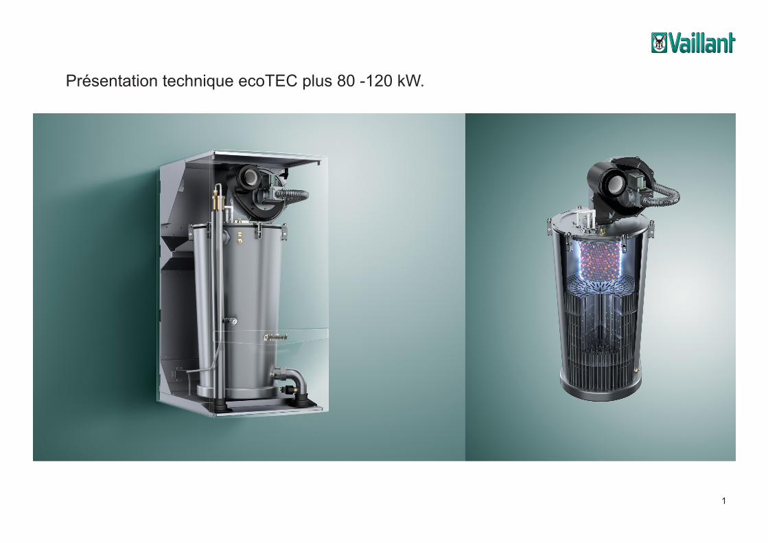
Type d’appareil Gaz Puissance de chauffage nominale P (kW) Modulation en %
ecoTEC plus VC 806G20/G25 (gaz nat. H)
Pas disponible pour le gaz liquide
16,5 - 82,3 (50/30 °C)14,9 - 74,7 (80/60 °C) ± 20 - 100
ecoTEC plus VC 1006 20,7 - 102,8 (50/30 °C)18,7 - 93,3 (80/60 °C) ± 20 - 100
ecoTEC plus VC 1206 24,7 - 123,4 (50/30 °C)22.4 - 112 (80/60 °C) ± 20 - 100
Types d’appareil
3
ecoTEC plus …/5 (80 – 120 kW)
Notes
11/2012 14 Training 0020139155_01
3 Planning and dimensioning
3.1 Planning requirements 3.1.1 Dimension drawing and connection measurements
Legend 1 Wall aperture for flue pipe 2 Flue pipe connection 3 Hanging bracket 4 Heating flow 5 Condensate siphon connection 6 Gas connection 7 Heating return
Minimum clearance for a roof duct through a wall or in a shaft
Dimension A [mm]
110/160 with 87° elbow, PP 477
110/160 with 87° elbow and inspection opening, PP 477
Dimension A for flue pipe wall breakthrough
G 1¼ appliance connection and G 1½ after the pump group
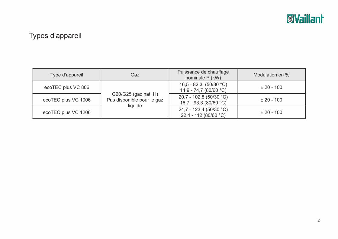
Dimensions de l’appareil ecoTEC plus
légende
1) Passage mural d’amenée d’air/évacuation gaz brûlés2) Amenée d’air/Evacuation gaz brûlés3) Support de l’appareil4) Départ de chauffage5) Raccordement de la conduite d’évacuation6) Raccordement gaz7) Retour de chauffage
4
ecoTEC plus …/5 (80 – 120 kW)
Notes
11/2012 55 Training 0020139155_01
4.2 Hydraulic design 4.2.1 ecoTEC VC/VU/VM/VHR functional diagram
ecoTEC plus VC/VU/VM/VHR functional diagram, 80 kW
ecoTEC plus …/5 (80 – 120 kW)
Notes
11/2012 53 Training 0020139155_01
4 Application technology
4.1 Overview of the important components
Appliance with open front cover (80 kW)
Flue gas pipe
Flexible gas pipe
Fan
Air intake pipe
Flue gas pressure switch
Integral-condensation Heat exchanger
Water pressure sensor
Automatic air vent
Ignition transfor-mator
Ionisation and ignition electrode
STL combustion chamber
Flow
Flow NTC
Pressure gauge
Return NTC
Gas valve
Flow STL
Return pipe
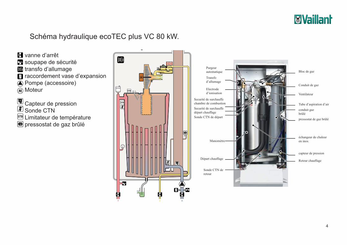
conduit gaz brûlé
Bloc de gaz
Ventilateur
Tube d’aspiration d’air
pressostat de gaz brûlé
échangeur de chaleur en inox
Sonde CTN de retour
Retour chauffage
capteur de pression
Transfo d’allumage
Départ chauffage
Purgeur automatique
Electrode d’ionisation
Securité de surchauffe chambre de combustion
Sonde CTN de départ
Manomètre
Securité de surchauffedépart chauffage
Conduit de gaz
ecoTEC plus …/5 (80 – 120 kW)
Notes
11/2012 56 Training 0020139155_01
ecoTEC plus VC/VU/VM/VHR functional diagram, 100,120 kW
vanne d’arrêtsoupape de sécuritétransfo d’allumageraccordement vase d’expansionPompe (accessoire)Moteur
Capteur de pressionSonde CTNLimitateur de températurepressostat de gaz brûlé
Schéma hydraulique ecoTEC plus VC 80 kW.
5
ecoTEC plus …/5 (80 – 120 kW)
Notes
11/2012 54 Training 0020139155_01
Appliances with open front cover (100, 120 kW) with electronic box
Flue gas pipe
Gas valve
Fan
Air intake pipe
Integral-condensation Heat exchanger
Water pressure sensor
Ignition trans-formator
Automatic air vent
Ionisation and ignition electrode
STL combustion chamber
Flow
Flow NTC
Pressure gauge Return NTC
Flow STL
Electronic box
Flue gas pressure switch
Return pipe
ecoTEC plus …/5 (80 – 120 kW)
Notes
11/2012 56 Training 0020139155_01
ecoTEC plus VC/VU/VM/VHR functional diagram, 100,120 kW
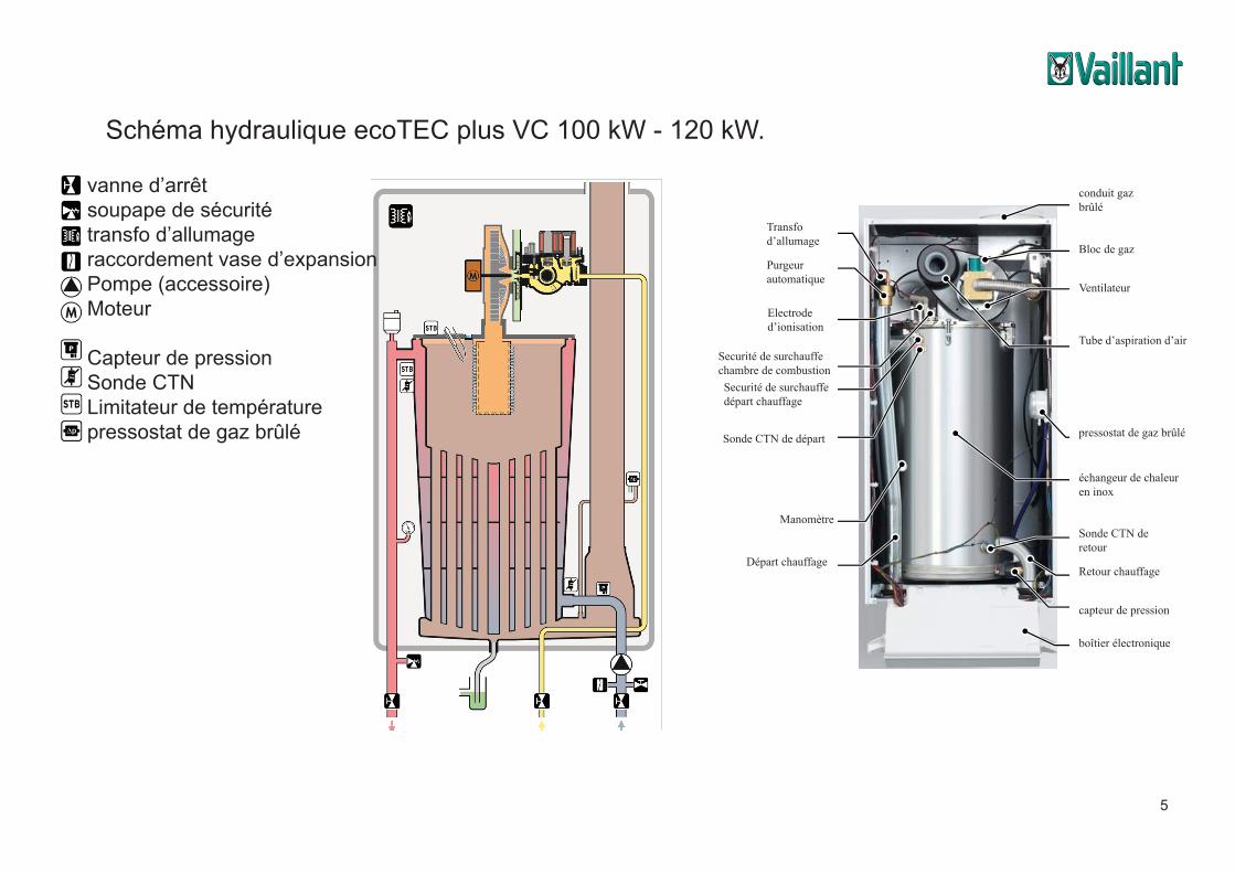
boîtier électronique
Schéma hydraulique ecoTEC plus VC 100 kW - 120 kW.
ecoTEC plus …/5 (80 – 120 kW)
Notes
11/2012 56 Training 0020139155_01
ecoTEC plus VC/VU/VM/VHR functional diagram, 100,120 kW
vanne d’arrêtsoupape de sécuritétransfo d’allumageraccordement vase d’expansionPompe (accessoire)Moteur
Capteur de pressionSonde CTNLimitateur de températurepressostat de gaz brûlé
conduit gaz brûlé
Bloc de gaz
Ventilateur
Tube d’aspiration d’air
pressostat de gaz brûlé
échangeur de chaleur en inox
Sonde CTN de retour
Retour chauffage
capteur de pression
Transfo d’allumage
Départ chauffage
Purgeur automatique
Electrode d’ionisation
Securité de surchauffe chambre de combustion
Sonde CTN de départ
Manomètre
Securité de surchauffedépart chauffage
6
ecoTEC plus …/5 (80 – 120 kW)
Notes
11/2012 62 Training 0020139155_01
After filling the system to more than 0.5 bar, the appliance automatically restarts and the fault message disappears. If air enters the appliance when refilling the system, the appliance can switch off with the fault message "F.75". Cause: When starting up the heating pump, the water pressure sensor checks whether the water pressure rises (pressure drop recognition). If air is found in the heating pump, the required pressure increase does not occur and the fault switch-off "F.75" occurs after five attempts. Remedy: Run the purging program "P.00" to fill the appliance return.
4.3.2 Integral condensation heat exchanger
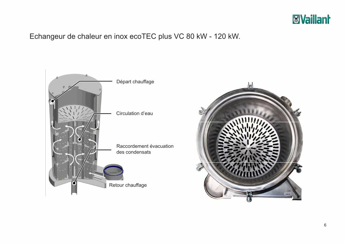
Section of the heat exchanger (image source: AIC) Perforated plate of a 120 KW appliance The entire heat exchanger, including all the fixtures, is made of stainless steel. The upper section of the heat exchanger, above the perforated plate, is the combustion chamber and this section is called the "heating value level", because only a low level of condensation forms here.
Heating flow connection
Water flow
Condensate drain
ecoTEC plus …/5 (80 – 120 kW)
Notes
11/2012 63 Training 0020139155_01
The lower section, below the perforated plate, contains oval-shaped pipes (147 pipes for 120 kW, 126 pipes for 100 kW, 91 pipes for 80 kW) with selective narrowing points through which the hot gas flows. Most of the condensation occurs here and it is there-fore called the "calorific value level". The flue gas that is to be cooled uses the guide plate (and the pump) to heat up the pipes to which the water in the heat exchanger flows from below in a meandering pattern to the interior, as shown in the drawing. The heat is then transferred in the counterflow principle and is therefore optimally trans-ferred. Any condensate that forms is caught in the condensate pan at the bottom and is guided to the condensate siphon in the centre. The upper section (combustion chamber) now holds the heated water, which passes to the heating distribution as flow water.
Heat exchanger of a 120 kW appliance, from above 4.3.2.1 Flue gas collector The flue gas collector surrounds the entire heat exchanger and is constructed from stainless steel up to the flue pipe connection. On the one hand, this is used as a con-densate collector and, on the other hand, it is used as a connection to the inner flue pipe. The air/flue gas duct is first connected to the unit's connection adapter.
Circulation d’eau
Raccordement évacuation des condensats
Echangeur de chaleur en inox ecoTEC plus VC 80 kW - 120 kW.
Départ chauffage
Retour chauffage
7
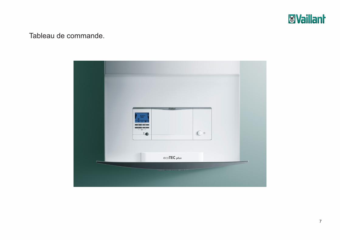
Tableau de commande.
8
ecoTEC plus …/5 (80 – 120 kW)
Notes
11/2012 76 Training 0020139155_01
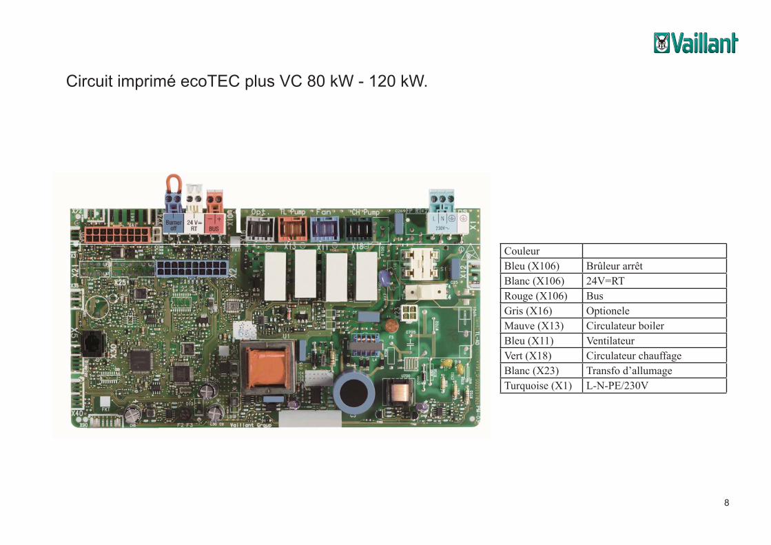
4.6 Electronics design 4.6.1 General The electronics on the appliance PCB can be used to implement all control and regula-tion functions on the appliance variants. The appliance state is permanently monitored, appliance faults analysed and shown on the display along with the appliance status and fault information. Important data is saved. The electronic controller, the power supply, the fan control and the fan housing are housed in the electronic PCB. The appliances do not have a separate supply trans-former. The task of the transformer is carried out by a switching power supply integrat-ed into the PCB. The ignition transformer is fitted externally in the upper left-hand cor-ner of the appliance. 4.6.2 New! ecoTEC plus PCB
ecoTEC plus PCB
CouleurBleu (X106) Brûleur arrêtBlanc (X106) 24V=RTRouge (X106) BusGris (X16) OptioneleMauve (X13) Circulateur boilerBleu (X11) VentilateurVert (X18) Circulateur chauffageBlanc (X23) Transfo d’allumageTurquoise (X1) L-N-PE/230V
Circuit imprimé ecoTEC plus VC 80 kW - 120 kW.
9
Communication modules
.
Technical Pictures: ecoTEC plus - components
Media Server picture server picture categories products product technics
ACC12_2905_01 ACC12_2906_01 ACC12_2907_01
Communication modules
.
Technical Pictures: ecoTEC plus - components
Media Server picture server picture categories products product technics
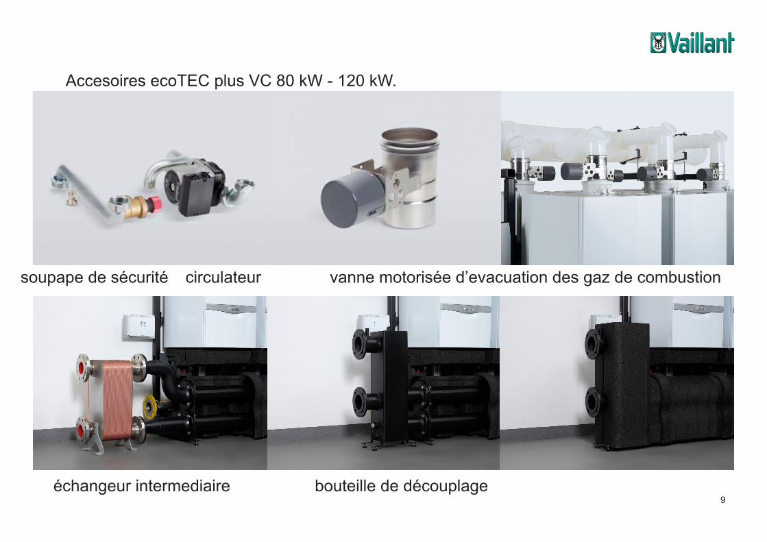
ACC12_2905_01 ACC12_2906_01 ACC12_2907_01vanne motorisée d’evacuation des gaz de combustioncirculateursoupape de sécurité
bouteille de découplageéchangeur intermediaire
Accesoires ecoTEC plus VC 80 kW - 120 kW.
10
Communication modulesTechnical Pictures: ecoTEC plus – Cascade in line
Media Server picture server picture categories products product technics
WHBC12_2726_01 WHBC12_2727_01
WHBC12_2729_01
WHBC12_2728_01
WHBC12_2730_01 WHBC12_2731_01
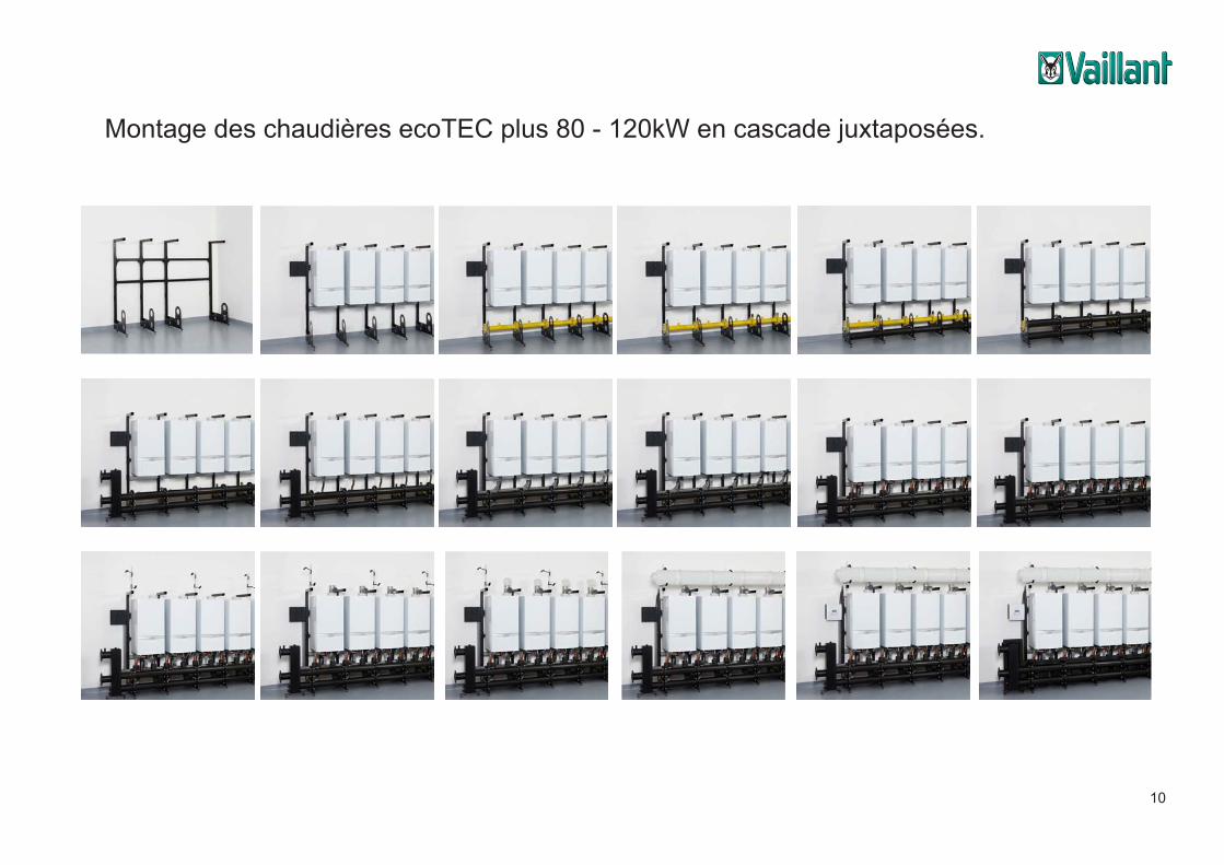
Montage des chaudières ecoTEC plus 80 - 120kW en cascade juxtaposées.Communication modulesTechnical Pictures: ecoTEC plus – Cascade in line
Media Server picture server picture categories products product technics
WHBC12_2738_01 WHBC12_2739_01 WHBC12_2740_01
WHBC12_2741_01 WHBC12_2742_01 WHBC12_2743_01
Communication modulesTechnical Pictures: ecoTEC plus – Cascade in line
Media Server picture server picture categories products product technics
WHBC12_2738_01 WHBC12_2739_01 WHBC12_2740_01
WHBC12_2741_01 WHBC12_2742_01 WHBC12_2743_01
Communication modulesTechnical Pictures: ecoTEC plus – Cascade in line
Media Server picture server picture categories products product technics
WHBC12_2745_01WHBC12_2744_01 WHBC12_2746_01
WHBC12_2747_01 WHBC12_2749_01WHBC12_2748_01
Communication modulesTechnical Pictures: ecoTEC plus – Cascade in line
Media Server picture server picture categories products product technics
WHBC12_2745_01WHBC12_2744_01 WHBC12_2746_01
WHBC12_2747_01 WHBC12_2749_01WHBC12_2748_01
Communication modulesTechnical Pictures: ecoTEC plus – Cascade in line
Media Server picture server picture categories products product technics
WHBC12_2738_01 WHBC12_2739_01 WHBC12_2740_01
WHBC12_2741_01 WHBC12_2742_01 WHBC12_2743_01
Communication modulesTechnical Pictures: ecoTEC plus – Cascade in line
Media Server picture server picture categories products product technics
WHBC12_2738_01 WHBC12_2739_01 WHBC12_2740_01
WHBC12_2741_01 WHBC12_2742_01 WHBC12_2743_01
Communication modulesTechnical Pictures: ecoTEC plus – Cascade in line
Media Server picture server picture categories products product technics
WHBC12_2745_01WHBC12_2744_01 WHBC12_2746_01
WHBC12_2747_01 WHBC12_2749_01WHBC12_2748_01
Communication modulesTechnical Pictures: ecoTEC plus – Cascade in line
Media Server picture server picture categories products product technics
WHBC12_2745_01WHBC12_2744_01 WHBC12_2746_01
WHBC12_2747_01 WHBC12_2749_01WHBC12_2748_01
Communication modulesTechnical Pictures: ecoTEC plus – Cascade in line
Media Server picture server picture categories products product technics
WHBC12_2738_01 WHBC12_2739_01 WHBC12_2740_01
WHBC12_2741_01 WHBC12_2742_01 WHBC12_2743_01
Communication modulesTechnical Pictures: ecoTEC plus – Cascade in line
Media Server picture server picture categories products product technics
WHBC12_2738_01 WHBC12_2739_01 WHBC12_2740_01
WHBC12_2741_01 WHBC12_2742_01 WHBC12_2743_01
Communication modulesTechnical Pictures: ecoTEC plus – Cascade in line
Media Server picture server picture categories products product technics
WHBC12_2745_01WHBC12_2744_01 WHBC12_2746_01
WHBC12_2747_01 WHBC12_2749_01WHBC12_2748_01
Communication modulesTechnical Pictures: ecoTEC plus – Cascade in line
Media Server picture server picture categories products product technics
WHBC12_2745_01WHBC12_2744_01 WHBC12_2746_01
WHBC12_2747_01 WHBC12_2749_01WHBC12_2748_01
Communication modulesTechnical Pictures: ecoTEC plus – Cascade in line
Media Server picture server picture categories products product technics
WHBC12_2750_01 WHBC12_2751_01 WHBC12_2752_01
WHBC12_2753_01 WHBC12_2754_01 WHBC12_2755_01
Communication modulesTechnical Pictures: ecoTEC plus – Cascade in line
Media Server picture server picture categories products product technics
WHBC12_2750_01 WHBC12_2751_01 WHBC12_2752_01
WHBC12_2753_01 WHBC12_2754_01 WHBC12_2755_01
Communication modulesTechnical Pictures: ecoTEC plus – Cascade in line
Media Server picture server picture categories products product technics
WHBC12_2750_01 WHBC12_2751_01 WHBC12_2752_01
WHBC12_2753_01 WHBC12_2754_01 WHBC12_2755_01
Communication modulesTechnical Pictures: ecoTEC plus – Cascade in line
Media Server picture server picture categories products product technics
WHBC12_2750_01 WHBC12_2751_01 WHBC12_2752_01
WHBC12_2753_01 WHBC12_2754_01 WHBC12_2755_01
Communication modulesTechnical Pictures: ecoTEC plus – Cascade in line
Media Server picture server picture categories products product technics
WHBC12_2750_01 WHBC12_2751_01 WHBC12_2752_01
WHBC12_2753_01 WHBC12_2754_01 WHBC12_2755_01
11
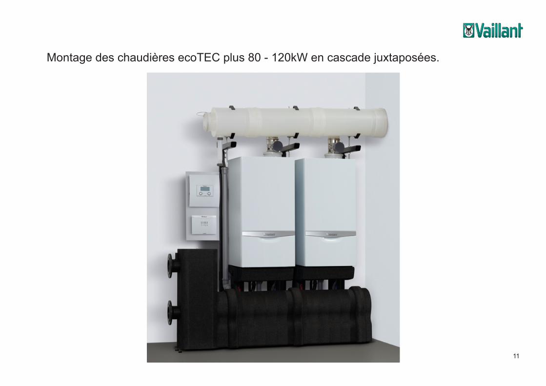
Montage des chaudières ecoTEC plus 80 - 120kW en cascade juxtaposées.
12
Communication modulesTechnical Pictures: ecoTEC plus – Cascade back to back
Media Server picture server picture categories products product technics
WHBC12_2846_01 WHBC12_2847_01
WHBC12_2849_01
WHBC12_2848_01
WHBC12_2850_01 WHBC12_2851_01
Communication modulesTechnical Pictures: ecoTEC plus – Cascade back to back
Media Server picture server picture categories products product technics
WHBC12_2846_01 WHBC12_2847_01
WHBC12_2849_01
WHBC12_2848_01
WHBC12_2850_01 WHBC12_2851_01
Communication modulesTechnical Pictures: ecoTEC plus – Cascade back to back
Media Server picture server picture categories products product technics
WHBC12_2853_01WHBC12_2852_01 WHBC12_2854_01
WHBC12_2855_01 WHBC12_2857_01WHBC12_2856_01
Communication modulesTechnical Pictures: ecoTEC plus – Cascade back to back
Media Server picture server picture categories products product technics
WHBC12_2853_01WHBC12_2852_01 WHBC12_2854_01
WHBC12_2855_01 WHBC12_2857_01WHBC12_2856_01
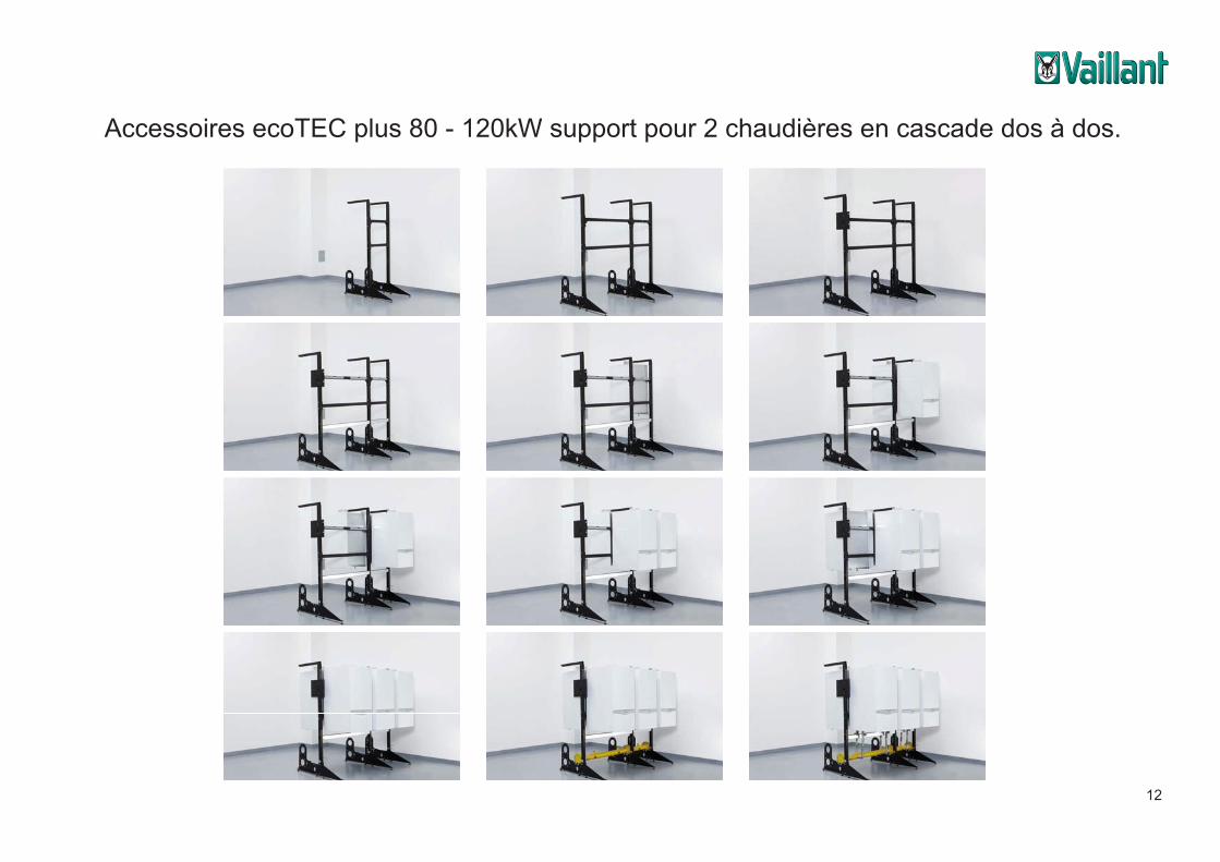
Accessoires ecoTEC plus 80 - 120kW support pour 2 chaudières en cascade dos à dos.
13
Communication modulesTechnical Pictures: ecoTEC plus – Cascade back to back
Media Server picture server picture categories products product technics
WHBC12_2858_01 WHBC12_2859_01 WHBC12_2860_01
WHBC12_2861_01 WHBC12_2862_01 WHBC12_2863_01
Communication modulesTechnical Pictures: ecoTEC plus – Cascade back to back
Media Server picture server picture categories products product technics
WHBC12_2865_01WHBC12_2864_01 WHBC12_2866_01
WHBC12_2867_01 WHBC12_2869_01WHBC12_2868_01
Communication modulesTechnical Pictures: ecoTEC plus – Cascade back to back
Media Server picture server picture categories products product technics
WHBC12_2858_01 WHBC12_2859_01 WHBC12_2860_01
WHBC12_2861_01 WHBC12_2862_01 WHBC12_2863_01
Communication modulesTechnical Pictures: ecoTEC plus – Cascade back to back
Media Server picture server picture categories products product technics
WHBC12_2865_01WHBC12_2864_01 WHBC12_2866_01
WHBC12_2867_01 WHBC12_2869_01WHBC12_2868_01
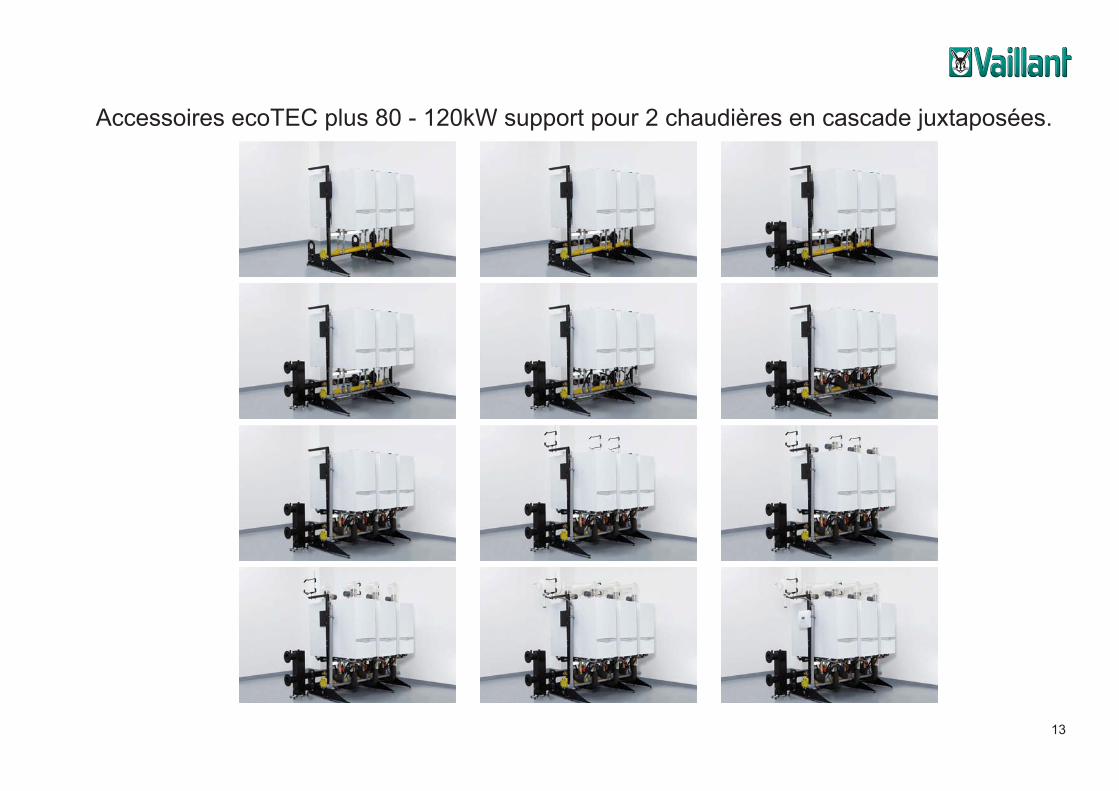
Accessoires ecoTEC plus 80 - 120kW support pour 2 chaudières en cascade juxtaposées.


N.V. Vaillant S.A.Rue Golden Hopestraat 15 ▪ B-1620 Drogenbos ▪ Tel. 02/3349300Fax 02/3349319 ▪ www.vaillant.be ▪ [email protected] 19/03/2013 - Modifications sous réserve