Embed Size (px)
Citation preview
Projet de Fin d’Etudes
Homogeneous Charge Thermal Ignition
By
Johan Jhigaï
Mechanical, Material and Aerospace Engineering
Department
Professor: Francisco Ruiz MMAE Department September2012

Rapport de Projet de Fin d’Etudes
JHIGAÏ GM5/MMAE September 2012
Rapport de Projet de Fin d’Etudes
JHIGAÏ GM5/MMAE September 2012
Institut National des Sciences Appliquées de Strasbourg
PROJET DE FIN D’ETUDES
Auteur : Johan Jhigaï Promotion :
Titre : Homogeneous Charge Thermal Ignition Soutenance : 12 septembre 2012
Structure d’accueil : Illinois Institute of Technology
Nb de volume(s) : Nb de pages : 57 Nb de références bibliographiques : 10
Résumé : Ce Projet de fin d’étude, traite de l’application de l’allumage thermique de charge homogène
comme alternative à l’allumage classique dans les moteurs à combustion interne réalisé par une bougie. Le
but étant d’obtenir une meilleure consommation d’essence tout en réduisant les émissions de polluants
comparé à un moteur essence conventionnel.
Dans ce rapport seront abordés les différents travaux réalisés concernant ce projet, notamment la
réalisation de prototype de cellules de test, ainsi que le traitement des résultats obtenus. Seront
également abordés les précédents concernant le sujet ainsi que les recommandations futures
quand au développement du procédé.
Mots clés : Moteur à combustion interne, allumage, rendement
Traduction: This final project has for subject the application oft he Homogeneous Charge Thermal
Ignition system as an alternative for the regular Spark Ignition internal combustion engines. The
goal being to obtain lower fuel consumption and lower pollutant emissions, compared to a regular
spark ignition engine.
In this report will be mentionned the various studies conducted regarding the project, such as the
making of the testing cells as well as the process of the data gathered. Will be also mentionned the
previous studies regarding the project and the major recommendations concerning the
development of the project.

Rapport de Projet de Fin d’Etudes
JHIGAÏ GM5/MMAE September 2012
Acknowledgement
I would like to thank the Illinois Institute of Technology for allowing me to follow their Master’s
degree program and giving me this opportunity to work on such a leading edge research project.
I would like also to thank INSA de Strasbourg, for giving me such a good preparation that allowed
me to face the challenges I encountered during this year at IIT.
My grateful thanks also to Professor Francisco Ruiz at IIT for accepting me in his research team
and letting me work on the HCTI project even though I had no experience at all regarding engines,
for his support, and trust during this project.
I would like to thank also Mr. Craig Johnson, great machinist at IIT, for his help in creating custom
made components, for his help with the engine manipulation, and for letting me use his tools and
laboratory.
I would like to thank Mr. Abhishek Chandnani and Mr. Cedric Zacarias Ramos Silva for their help,
their patience and their will to learn during this project.
I would like to thank Mr. Juan I Domenech and Alejandro Assens Blanch, also working on the
project for their help and will to share their experience with engines, they taught me a lot.
Finally, I would like to thank my family for their unconditional trust and faith in me, their
encouragement to work harder, and their support.
Rapport de Projet de Fin d’Etudes
JHIGAÏ GM5/MMAE September 2012
Table of Contents PROJET DE FIN D’ETUDES .................................................................................................................... 3
Acknowledgement .............................................................................................................................. 4
I. Introduction ................................................................................................................................ 6
II. Fundamentals of Homogeneous Charge Thermal Ignition ......................................................... 9
A. Design .................................................................................................................................... 10
B. Working cycle ........................................................................................................................ 12
C. Experimental Set-Up and Procedures ................................................................................... 13
D. Data representation and results ........................................................................................... 18
E. Conclusion ............................................................................................................................. 23
III. Engine rehabilitation and experimental setup ......................................................................... 25
A. Engine rehabilitation ............................................................................................................. 25
B. Formation .............................................................................................................................. 29
C. Experimental setup ............................................................................................................... 30
IV. Data representation .................................................................................................................. 35
A. Setup ..................................................................................................................................... 35
B. Design .................................................................................................................................... 37
1. Ceramic mass in chamber construction ............................................................................ 37
2. Glow plug in combustion sub-chamber construction ....................................................... 37
3. Tungsten wire spire in combustion sub-chamber construction ....................................... 38
4. Ceramics in combustion sub-chamber construction ........................................................ 38
C. Data collected ....................................................................................................................... 39
1. Tungsten wire spire pressure graphs ................................................................................ 39
D. HCTI Thermodynamic cycle: .................................................................................................. 41
V. Conclusions and Recommendation........................................................................................... 42
VI. Figures ....................................................................................................................................... 45
Bibliography ...................................................................................................................................... 47
Appendixes ........................................................................................................................................ 49
A. Calculations ............................................................................................................................... 49
B. Alternator part list and diagram ............................................................................................... 52
C. Engine part list and diagrams .................................................................................................... 54
D. Tecumseh carburetors .............................................................................................................. 58
Rapport de Projet de Fin d’Etudes
JHIGAÏ GM5/MMAE September 2012
I. Introduction
For more than two and a half century now, heat engines have served mankind.
During the first 150 years, water transformed into steam, was interposed between the
combustion gases obtained by burning the fuel and the work producing piston. In the 1860s
finally, the internal combustion engine became a practical reality with engines using coal-gas air
mixtures at atmospheric pressure. The first marketable engines of this type were developed by J.
J. E. Lenoir, and around 5000 were built between 1860 and 1865, with efficiency about 5 percent.
A more successful engine was the atmospheric engine introduced in 1867 by Nicolaus A. Otto and
Eugen Langen, using the pressure rise from the combustion of the fuel-air charge to create a
vacuum in the cylinder. Abourt 5000 were built, with thermal efficiencies of up to 11 percent.
To overcome the engine’s low thermal efficiency, Otto proposed and engine cycle with four piston
strokes: intake, compression, ignition and expansion, the last one being the power stroke. His first
prototype ran in 1876. There was an enormous reduction in engine weight and volume, and it’s
been the breakthrough that launched the internal combustion engine industry. By 1890, nearly
50,000 of these engines had been sold.
An unpublished French patent issued in 1862 to Alphonse Beau de Rochas was found which
described the principles of the four-stroke cycle, casting a doubt on Otto’s patent. But even if
Beau de Rocha’s patent predates Otto’s developments, he never put his idea in practice, making
Otto the inventor of the modern internal combustion engine as we know it.
Other developments followed fast: several engineers like James Robson in England and Karl Benz
in Germany had successfully developed two-stroke internal combustion engines where the
exhaust and intake processes occur during the end of the power stroke and the beginning of the
compression stroke.
It was recognized that efficiency was function of the expansion ratio, but compression ratios were
limited to less than four with the available fuels at that time to avoid knock problems.
Carburetor and ignition system developments were to happen before high-speed gasoline engines
suitable for automobiles became available in the late 1880s, as stationary engine progress also
continued.
In 1892, the German engineer Rudolph Diesel described in his patent a new form of internal
combustion engine: his concept of starting combustion by injecting a liquid fuel into air heated
only by compression doubled the efficiency over other internal combustion engines. Greater
expansion ratios, without detonation or knock became possible.
Engine developments continued, widening the internal combustion engine markets. For example,
the rotary internal combustion engine has been a major finding, with the first practical one,
created by Felix Wankel, and successfully tested in 1957.
Fuel also had a huge impact on engine development, new fuels allowing higher compression
ratios with fewer risks of knock, influencing production of new carburetors and electric starters.
The antiknock effect of tetraethyl lead was discovered at General Motors and made available as a
Rapport de Projet de Fin d’Etudes
JHIGAÏ GM5/MMAE September 2012
gasoline additive in the US in 1923 [1].
New factors affect now the engine design and operation: the need to control the automotive
urban air pollution and the ne need to achieve better fuel consumption. Substantial emission
reductions have been achieved for both spark and compression ignition engines. Work is being
done on the use of alternative fuels to gasoline and diesel.
After a century of development, the internal combustion engine can appear at its peak, with no
more potential for further improvement, but this is not the case: new materials are becoming
available, offering the possibility to reduce engine weight, cost and heat loss, and to create new
types of internal combustion engines such as the stratified-charge.
Since the 1920s, it’s been tried to develop hybrid internal combustion engine that combines
features of the spark and compression engine. The goal being to operate at the optimum
compression ratio, around 12 to 15 by injecting the fuel directly into the combustion chamber
during the compression process, thus avoiding knock or spontaneous ignition problem that limits
spark ignition engines with their premixed charge, and igniting the fuel as it mixes with air with a
spark plug to provide direct control of the ignition process and thereby avoid the fuel ignition
quality requirement of the diesel.
Such engines are called “stratified-charge engines”.
Another concept that improves both the fuel consumption and the emission norms is the
Homogeneous Charge Combustion. Homogeneous Charge Compression Ignition has been adapted
and sold since 2007. Compared to conventional spark ignition engines, the fuel efficiency of an
HCCI engine was noted to have increased from 15% to 30% at 1.5 BMP, which is equivalent to
50% reduction in fuel consumption [2]. The main reason for this is the use of multiple flame front
combustion with lean charge. It makes the combustion rapid and increases the chances for a
complete combustion. A HCCI engine is built similar to compression ignition engines, for high
compression ratio, but the charge is supplied in premixed condition. Unfortunately, the
drawbacks are higher HC and CO emission than a regular spark ignition engine and a limited range
of operation [3]
Now, what would need to be found out is if multiple flame fronts, lean combustion can be applied
to gasoline engines in order to combine lower emission with higher fuel efficiency. Spark ignition
engines use a single flame front created by the spark of the spark plug [4]. Because of this, inside
the combustion chamber we have the burnt zone, the unburnt zone and the reaction zone. The
propagation of the reaction zone forms the flame front. As the combustion process takes time to
travel through the chamber, unburnt and partially burnt fuel, usually close to the cylinder walls
are ejected during the exhaust. It is considered as a major reason for poor efficiency of spark
ignition engines. Therefore, it could be interesting to have an ignition with multiple flame fronts
as it’s one of the suggested solutions for the problem of cycle-to-cyle variation responsible for the
drop in efficiency [5].

Rapport de Projet de Fin d’Etudes
JHIGAÏ GM5/MMAE September 2012
Figure 1: Combustion in spark ignition engine […]
The Homogeneous Charge Thermal ignition system (HCTI) is a concept that could in theory
increase the efficiency and lower the emissions of an engine by creating multiple flame fronts
with the use of heat for the ignition, hence replacing the spark ignition. Emissions in spark ignition
engines are sensitive to the air-fuel ratio[1].So HCTI system which purpose is to operate engines
with leaner mixtures, could in theory at the same time reduce emissions and increase fuel
efficiency.
Figure 2: SI engine emissions at various air-fuel ratios [...]
Experiment had previously been conducted on the Homogeneous Charge Thermal Ignition system
but it was difficult to keep the engine running for conducting the tests due to combustions
problems.
Solving this problem was the primary aim M. Chandrasekhar, working under professor Ruiz’s
direction on the HCTI system in 2009. He stabilized and sustained combustion and conducted
performance and emission tests on engines in HCTI and Spark-Ignition mode. His results will be
discussed further later in this report.
After the challenges faced and the observations made during his experiments, he suggested that
the determination of the thermodynamic cycle of the HCTI engine would help understand the
engine better.
The aim of my research project was first to rebuild the engine and then to obtain the
thermodynamic cycle in both modes to compare and obtain new information on the benefits of
the HCTI system.

Rapport de Projet de Fin d’Etudes
JHIGAÏ GM5/MMAE September 2012
II. Fundamentals of Homogeneous Charge Thermal Ignition
Even though the concept of Homogeneous Charge Thermal Ignition is relatively new, the thermal
ignition itself is an old concept that dates back to the mid 19th century. A patent was filed by
William Barnett in 1838 for the first single-acting engine, in which the energy source was a spongy
platina, platinum like wire compressed into mass. In 1844 John Reynolds invented a system
designed a system where electric current from a voltaic cell was heating a thin platinum mass in
order to ignite the mixture. Other designs used thermal or incandescent sources for igniting in
engines. Mr Alfred Drakes in 1843 or Atknison in 1879 used heated tube igniters [4]. In 1878
Dugald Clerk developed an incandescent platinum cage, which was fixed inside the engine in
order for it to gain heat from the explosion in the cylinder [7].
Now, glow plugs are used in some diesel engines for cold starts. New concepts such as smart
plugs are being searched. They are self-sustaining ignition system, using a pre-chamber with a
catalytic heating element. A small amount of air-fuel mixture enters the pre-chamber and is
ignited by a heater wire, initiating the combustion in the main chamber [8].
Figure 3: smart plug [10]
The goal of the HCTI system is to achieve better combustion in gasoline engines. The concept is to
make combustion happen with lean mixture and multiple flame fronts like HCCI system. Regular
spark plug ignition has proven to be inefficient with lean mixtures. For the HCTI engines, a porous
thermal piece of ceramic, also known as silicon carbide is used to ignite the mixture. This material
is known for being able to withstand very high temperatures and retain heat.
M. Chandrasekhar who wrote his thesis on the HCTI system has been one of the first to actually
succeed in sustaining the combustion in HCTI engines and obtaining usable data on the subject.
Since my goal was to pursue his work using the same engine and the design he made, I’ll first
present his work and results.
Rapport de Projet de Fin d’Etudes
JHIGAÏ GM5/MMAE September 2012
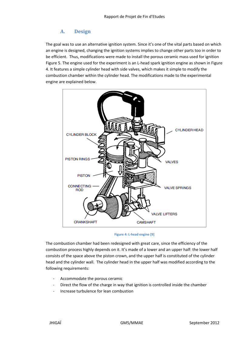
A. Design
The goal was to use an alternative ignition system. Since it’s one of the vital parts based on which
an engine is designed, changing the ignition systems implies to change other parts too in order to
be efficient. Thus, modifications were made to install the porous ceramic mass used for ignition
Figure 5. The engine used for the experiment is an L-head spark ignition engine as shown in Figure
4. It features a simple cylinder head with side valves, which makes it simple to modify the
combustion chamber within the cylinder head. The modifications made to the experimental
engine are explained below.
Figure 4: L-head engine [9]
The combustion chamber had been redesigned with great care, since the efficiency of the
combustion process highly depends on it. It’s made of a lower and an upper half: the lower half
consists of the space above the piston crown, and the upper half is constituted of the cylinder
head and the cylinder wall. The cylinder head in the upper half was modified according to the
following requirements:
- Accommodate the porous ceramic
- Direct the flow of the charge in way that ignition is controlled inside the chamber
- Increase turbulence for lean combustion
Rapport de Projet de Fin d’Etudes
JHIGAÏ GM5/MMAE September 2012
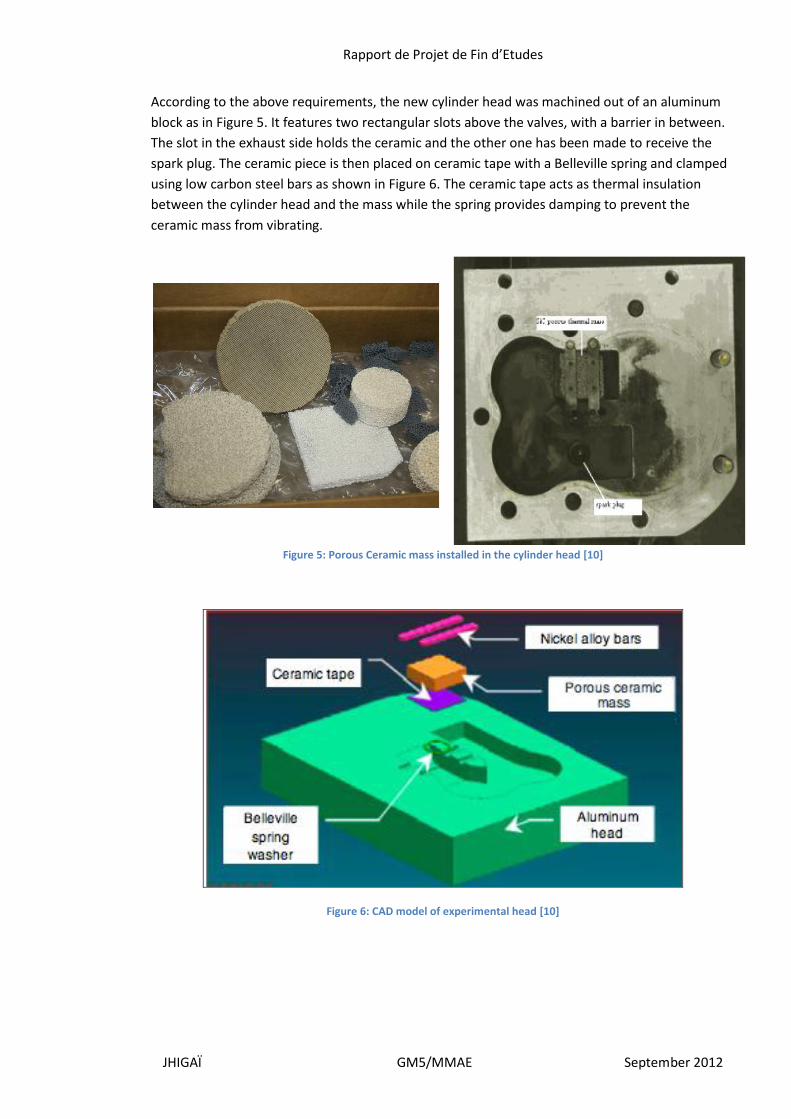
According to the above requirements, the new cylinder head was machined out of an aluminum
block as in Figure 5. It features two rectangular slots above the valves, with a barrier in between.
The slot in the exhaust side holds the ceramic and the other one has been made to receive the
spark plug. The ceramic piece is then placed on ceramic tape with a Belleville spring and clamped
using low carbon steel bars as shown in Figure 6. The ceramic tape acts as thermal insulation
between the cylinder head and the mass while the spring provides damping to prevent the
ceramic mass from vibrating.
Figure 5: Porous Ceramic mass installed in the cylinder head [10]
Figure 6: CAD model of experimental head [10]

Rapport de Projet de Fin d’Etudes
JHIGAÏ GM5/MMAE September 2012
Changing the combustion chamber changed the flow pattern inside it. With this design, the fuel
enters the cylinder through the inlet valve during the intake stroke, the barrier prevents the
charge from coming in contact with the hot ceramic, preventing pre-ignition, and the charge flows
tangentially, creating a vortex. The compression stroke squishes then the charge through the
ceramic because of the swirl, the charge absorbs heat from the ceramic and various points in the
charge ignite, enabling multiple flame front. During the exhaust, the hot gases are forced through
the ceramic in order for it to absorb heat. This cycle is what is expected with the design described
above, but it still has to be verified with flow diagnostic equipment.
B. Working cycle
The working cycle of the HCTI engine is the same as that of a conventional four stroke Spark-
ignition engine as shown in Figure 7. The fuel used is the same, and the charge is made using a
carburetor.
The purpose of the carburetor is to maintain the quality of the charge, and can be used to
manipulate the mixture, make it leaner or richer. The engine is started in SI mode via the spark
plug, which is disconnected after a couple of minutes, when the ceramic has gained enough heat
to sustain the cycle.
Figure 7: Working cycle of HCTI and SI four stroke engines [9]
Rapport de Projet de Fin d’Etudes
JHIGAÏ GM5/MMAE September 2012
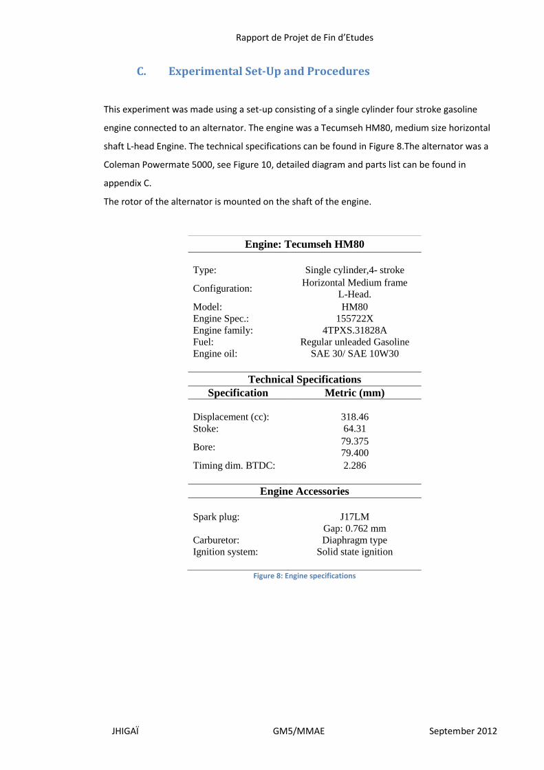
C. Experimental Set-Up and Procedures
This experiment was made using a set-up consisting of a single cylinder four stroke gasoline
engine connected to an alternator. The engine was a Tecumseh HM80, medium size horizontal
shaft L-head Engine. The technical specifications can be found in Figure 8.The alternator was a
Coleman Powermate 5000, see Figure 10, detailed diagram and parts list can be found in
appendix C.
The rotor of the alternator is mounted on the shaft of the engine.
Figure 8: Engine specifications
Engine: Tecumseh HM80
Type: Single cylinder,4- stroke
Configuration: Horizontal Medium frame
L-Head.
Model: HM80
Engine Spec.: 155722X
Engine family: 4TPXS.31828A
Fuel: Regular unleaded Gasoline
Engine oil: SAE 30/ SAE 10W30
Technical Specifications
Specification Metric (mm)
Displacement (cc): 318.46
Stoke: 64.31
Bore: 79.375
79.400
Timing dim. BTDC: 2.286
Engine Accessories
Spark plug: J17LM
Gap: 0.762 mm
Carburetor: Diaphragm type
Ignition system: Solid state ignition
Rapport de Projet de Fin d’Etudes
JHIGAÏ GM5/MMAE September 2012
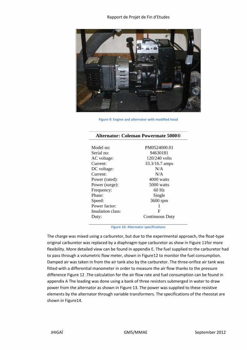
Figure 9: Engine and alternator with modified head
Alternator: Coleman Powermate 5000®
Model no: PM0524000.01
Serial no: 94630181
AC voltage: 120/240 volts
Current: 33.3/16.7 amps
DC voltage: N/A
Current: N/A
Power (rated): 4000 watts
Power (surge): 5000 watts
Frequency: 60 Hz
Phase: Single
Speed: 3600 rpm
Power factor: 1
Insulation class: F
Duty: Continuous Duty
Figure 10: Alternator specifications
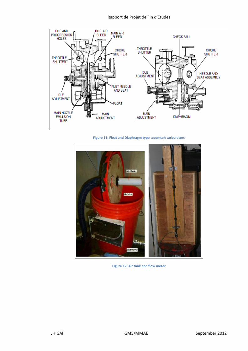
The charge was mixed using a carburetor, but due to the experimental approach, the float-type
original carburetor was replaced by a diaphragm-type carburetor as show in Figure 11for more
flexibility. More detailed view can be found in appendix E. The fuel supplied to the carburetor had
to pass through a volumetric flow meter, shown in Figure12 to monitor the fuel consumption.
Damped air was taken in from the air tank also by the carburetor. The three-orifice air tank was
fitted with a differential manometer in order to measure the air flow thanks to the pressure
difference Figure 12 .The calculation for the air flow rate and fuel consumption can be found in
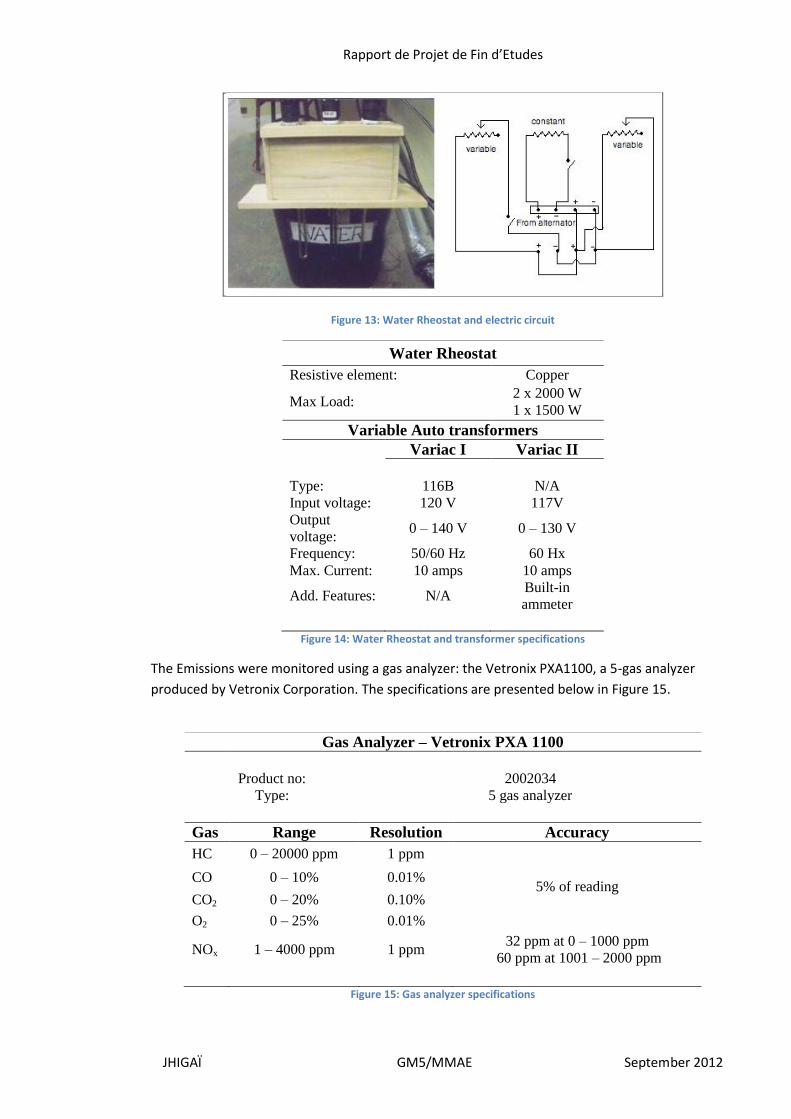
appendix A The loading was done using a bank of three resistors submerged in water to draw
power from the alternator as shown in Figure 13. The power was supplied to these resistive
elements by the alternator through variable transformers. The specifications of the rheostat are
shown in Figure14.
Rapport de Projet de Fin d’Etudes
JHIGAÏ GM5/MMAE September 2012
Figure 11: Float and Diaphragm type tecumseh carburetors
Figure 12: Air tank and flow meter
Rapport de Projet de Fin d’Etudes
JHIGAÏ GM5/MMAE September 2012
Figure 13: Water Rheostat and electric circuit
Water Rheostat
Resistive element: Copper
Max Load: 2 x 2000 W
1 x 1500 W
Variable Auto transformers
Variac I Variac II
Type: 116B N/A
Input voltage: 120 V 117V
Output
voltage: 0 – 140 V 0 – 130 V
Frequency: 50/60 Hz 60 Hx
Max. Current: 10 amps 10 amps
Add. Features: N/A Built-in
ammeter
Figure 14: Water Rheostat and transformer specifications
The Emissions were monitored using a gas analyzer: the Vetronix PXA1100, a 5-gas analyzer
produced by Vetronix Corporation. The specifications are presented below in Figure 15.
Gas Analyzer – Vetronix PXA 1100
Product no: 2002034
Type: 5 gas analyzer
Gas Range Resolution Accuracy
HC 0 – 20000 ppm 1 ppm
5% of reading CO 0 – 10% 0.01%
CO2 0 – 20% 0.10%
O2 0 – 25% 0.01%
NOx 1 – 4000 ppm 1 ppm 32 ppm at 0 – 1000 ppm
60 ppm at 1001 – 2000 ppm
Figure 15: Gas analyzer specifications
Rapport de Projet de Fin d’Etudes
JHIGAÏ GM5/MMAE September 2012
Figure 16: Gas analyzer
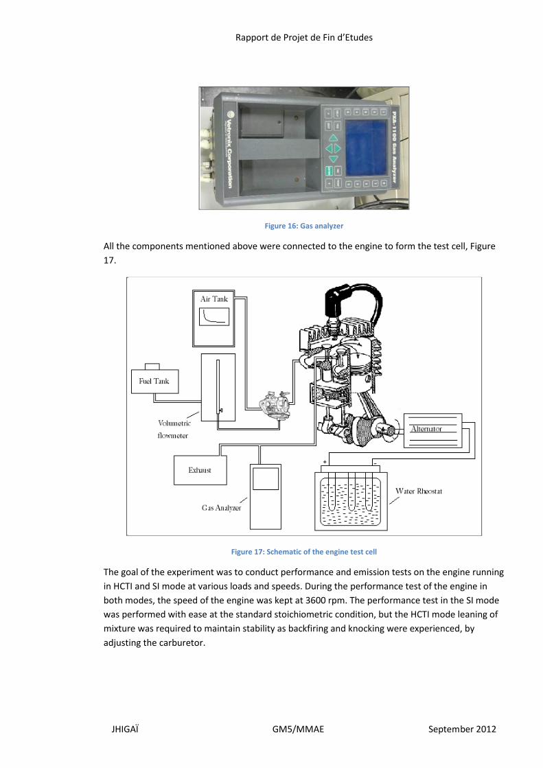
All the components mentioned above were connected to the engine to form the test cell, Figure
17.
Figure 17: Schematic of the engine test cell
The goal of the experiment was to conduct performance and emission tests on the engine running
in HCTI and SI mode at various loads and speeds. During the performance test of the engine in
both modes, the speed of the engine was kept at 3600 rpm. The performance test in the SI mode
was performed with ease at the standard stoichiometric condition, but the HCTI mode leaning of
mixture was required to maintain stability as backfiring and knocking were experienced, by
adjusting the carburetor.
Rapport de Projet de Fin d’Etudes
JHIGAÏ GM5/MMAE September 2012
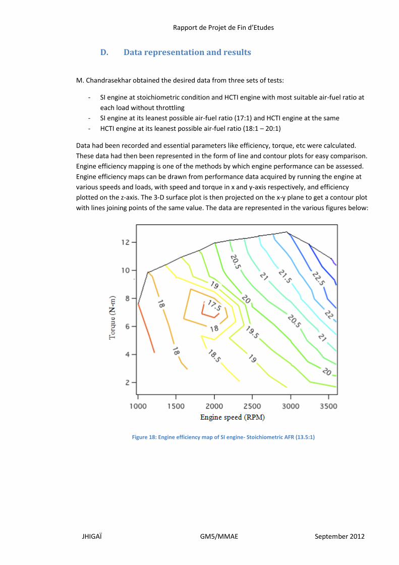
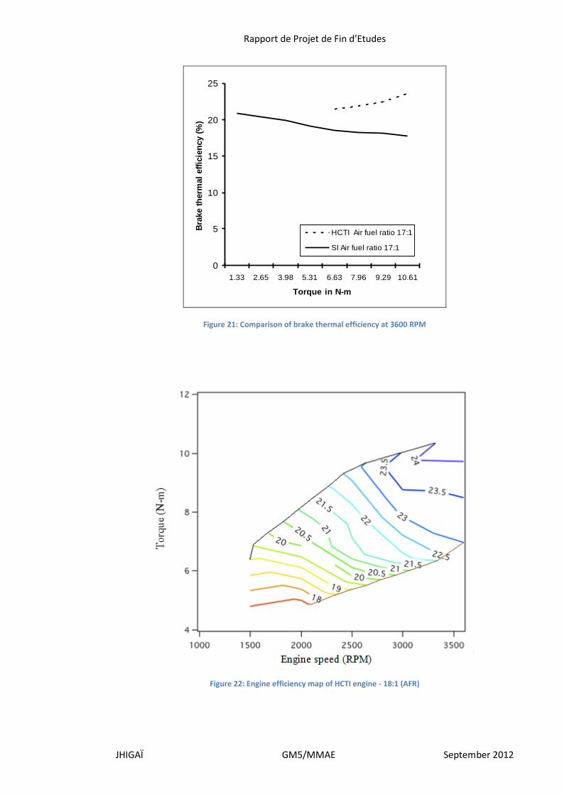
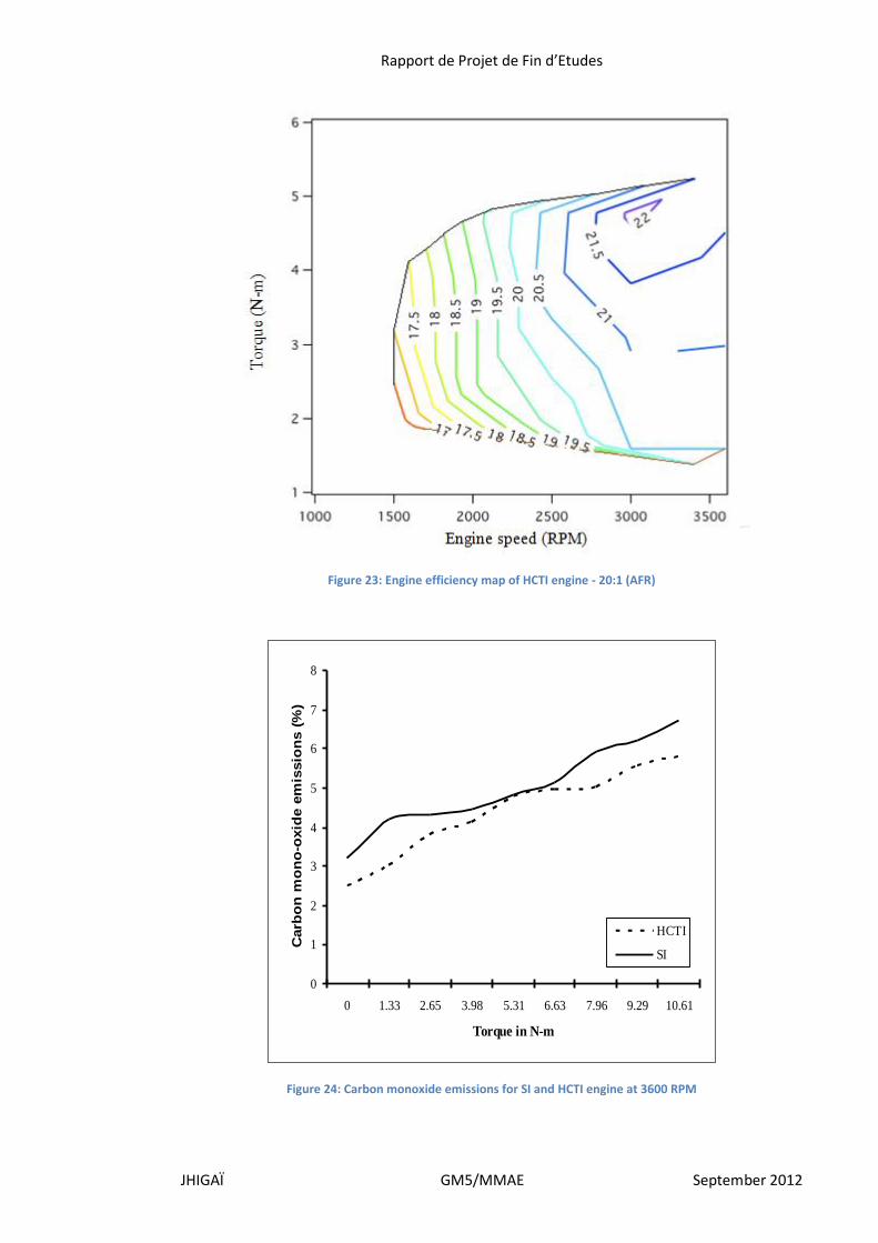
D. Data representation and results
M. Chandrasekhar obtained the desired data from three sets of tests:
- SI engine at stoichiometric condition and HCTI engine with most suitable air-fuel ratio at
each load without throttling
- SI engine at its leanest possible air-fuel ratio (17:1) and HCTI engine at the same
- HCTI engine at its leanest possible air-fuel ratio (18:1 – 20:1)
Data had been recorded and essential parameters like efficiency, torque, etc were calculated.
These data had then been represented in the form of line and contour plots for easy comparison.
Engine efficiency mapping is one of the methods by which engine performance can be assessed.
Engine efficiency maps can be drawn from performance data acquired by running the engine at
various speeds and loads, with speed and torque in x and y-axis respectively, and efficiency
plotted on the z-axis. The 3-D surface plot is then projected on the x-y plane to get a contour plot
with lines joining points of the same value. The data are represented in the various figures below:
Figure 18: Engine efficiency map of SI engine- Stoichiometric AFR (13.5:1)
Rapport de Projet de Fin d’Etudes
JHIGAÏ GM5/MMAE September 2012
Figure 19: Engine efficiency map of SI engine-Leanest AFR (17:1)
Figure 20: Efficiency map of HCTI engine at 17:1 (AFR)
Rapport de Projet de Fin d’Etudes
JHIGAÏ GM5/MMAE September 2012
Figure 21: Comparison of brake thermal efficiency at 3600 RPM
Figure 22: Engine efficiency map of HCTI engine - 18:1 (AFR)
0
5
10
15
20
25
1.33 2.65 3.98 5.31 6.63 7.96 9.29 10.61
Torque in N-m
Bra
ke t
herm
al
eff
icie
ncy (
%)
HCTI Air fuel ratio 17:1
SI Air fuel ratio 17:1
Rapport de Projet de Fin d’Etudes
JHIGAÏ GM5/MMAE September 2012
Figure 23: Engine efficiency map of HCTI engine - 20:1 (AFR)
Figure 24: Carbon monoxide emissions for SI and HCTI engine at 3600 RPM
0
1
2
3
4
5
6
7
8
0 1.33 2.65 3.98 5.31 6.63 7.96 9.29 10.61
Torque in N-m
Carb
on
mo
no
-oxid
e e
mis
sio
ns (
%)
HCTI
SI
Rapport de Projet de Fin d’Etudes
JHIGAÏ GM5/MMAE September 2012
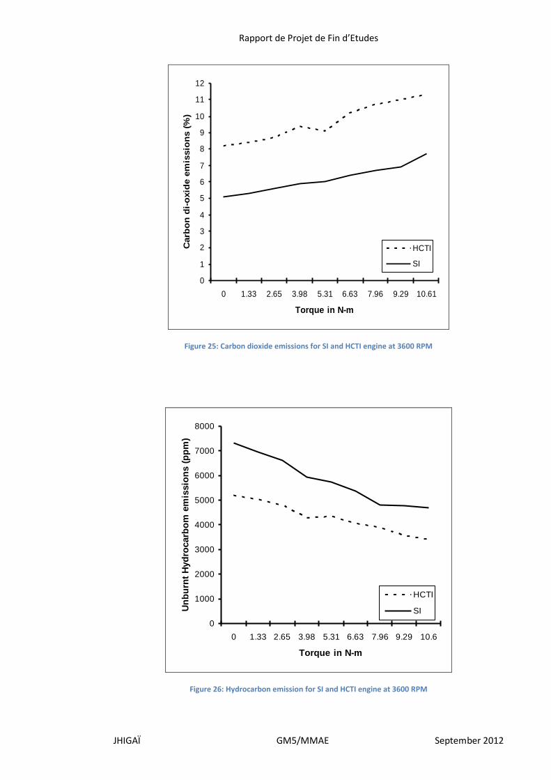
Figure 25: Carbon dioxide emissions for SI and HCTI engine at 3600 RPM
Figure 26: Hydrocarbon emission for SI and HCTI engine at 3600 RPM
0
1
2
3
4
5
6
7
8
9
10
11
12
0 1.33 2.65 3.98 5.31 6.63 7.96 9.29 10.61
Torque in N-m
Carb
on
di-
oxid
e e
mis
sio
ns (
%)
HCTI
SI
0
1000
2000
3000
4000
5000
6000
7000
8000
0 1.33 2.65 3.98 5.31 6.63 7.96 9.29 10.6
Torque in N-m
Un
bu
rnt
Hyd
rocarb
om
em
issio
ns (
pp
m)
HCTI
SI
Rapport de Projet de Fin d’Etudes
JHIGAÏ GM5/MMAE September 2012
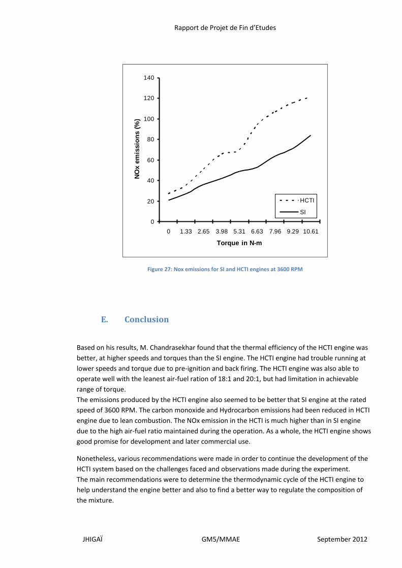
Figure 27: Nox emissions for SI and HCTI engines at 3600 RPM
E. Conclusion
Based on his results, M. Chandrasekhar found that the thermal efficiency of the HCTI engine was
better, at higher speeds and torques than the SI engine. The HCTI engine had trouble running at
lower speeds and torque due to pre-ignition and back firing. The HCTI engine was also able to
operate well with the leanest air-fuel ration of 18:1 and 20:1, but had limitation in achievable
range of torque.
The emissions produced by the HCTI engine also seemed to be better that SI engine at the rated
speed of 3600 RPM. The carbon monoxide and Hydrocarbon emissions had been reduced in HCTI
engine due to lean combustion. The NOx emission in the HCTI is much higher than in SI engine
due to the high air-fuel ratio maintained during the operation. As a whole, the HCTI engine shows
good promise for development and later commercial use.
Nonetheless, various recommendations were made in order to continue the development of the
HCTI system based on the challenges faced and observations made during the experiment.
The main recommendations were to determine the thermodynamic cycle of the HCTI engine to
help understand the engine better and also to find a better way to regulate the composition of
the mixture.
0
20
40
60
80
100
120
140
0 1.33 2.65 3.98 5.31 6.63 7.96 9.29 10.61
Torque in N-m
NO
x e
mis
sio
ns (
%)
HCTI
SI
Rapport de Projet de Fin d’Etudes
JHIGAÏ GM5/MMAE September 2012
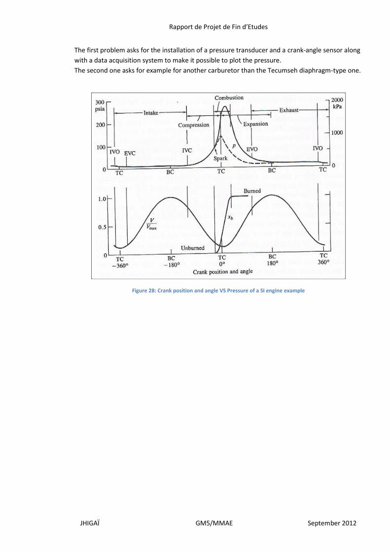
The first problem asks for the installation of a pressure transducer and a crank-angle sensor along
with a data acquisition system to make it possible to plot the pressure.
The second one asks for example for another carburetor than the Tecumseh diaphragm-type one.
Figure 28: Crank position and angle VS Pressure of a SI engine example
Rapport de Projet de Fin d’Etudes
JHIGAÏ GM5/MMAE September 2012
III. Engine rehabilitation and experimental setup
A. Engine rehabilitation
Between 2009 and 2012, the HCTI project has been conducted by other students. As a result of
changing hands and periods without work, during for example breaks, the experimental set up
created by M. Chandrasekhar had been mostly broken or lost. Out of the two Tecumseh HM80
engines available for the experiment, one had been broken beyond repair and the only one left
had been badly damaged. My first task as a new researcher in the lab was to get familiar to it, and
also to fix the engine left in order to resume the experiment.
First of all, I acquired all the data I could, on internal combustion engines first, and then on
Tecumseh engines. With the knowledge gained, I tried to figure out what was missing exactly and
what had to be fixed. It took a long time to try to find every scattered pieces of the previous
experiment, as well as to know how to manipulate the engine. Many parts could not be found.
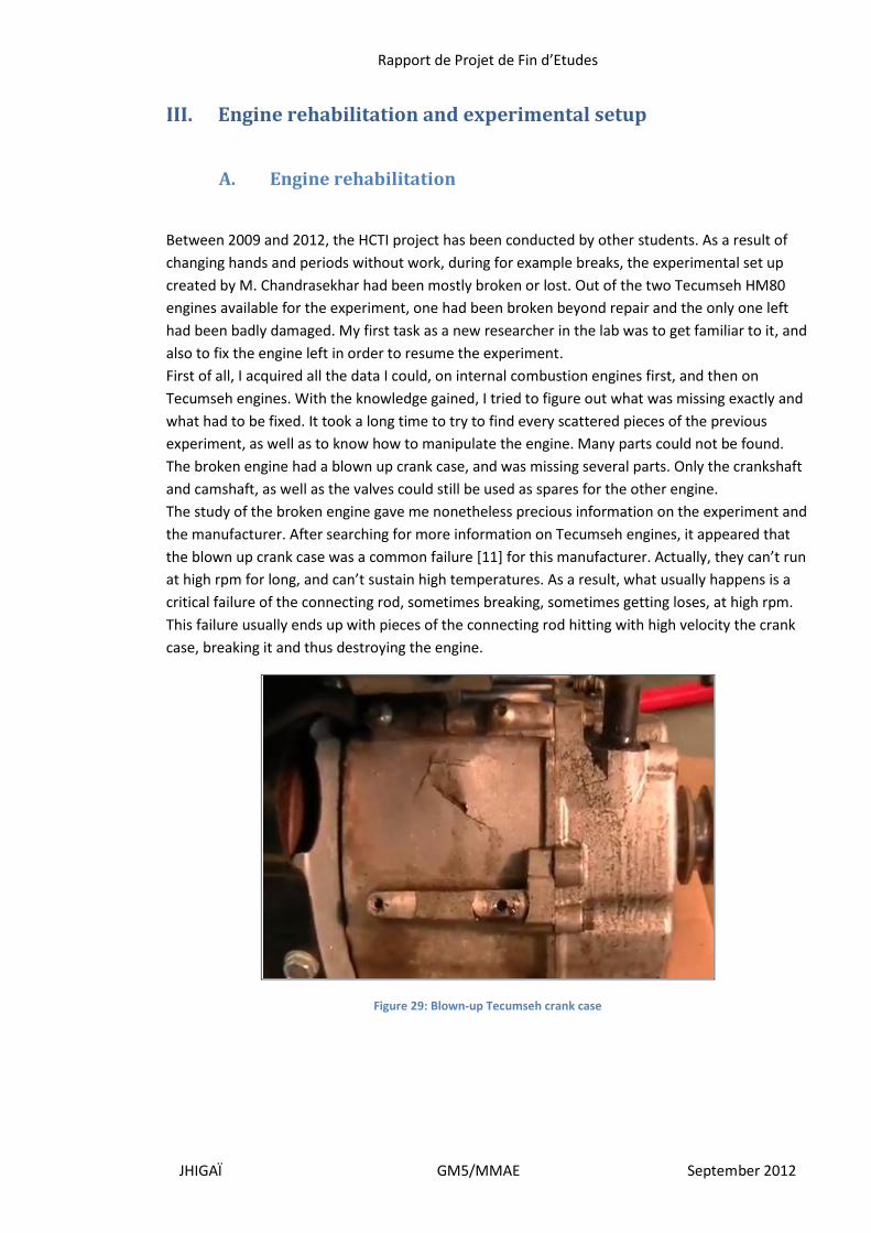
The broken engine had a blown up crank case, and was missing several parts. Only the crankshaft
and camshaft, as well as the valves could still be used as spares for the other engine.
The study of the broken engine gave me nonetheless precious information on the experiment and
the manufacturer. After searching for more information on Tecumseh engines, it appeared that
the blown up crank case was a common failure [11] for this manufacturer. Actually, they can’t run
at high rpm for long, and can’t sustain high temperatures. As a result, what usually happens is a
critical failure of the connecting rod, sometimes breaking, sometimes getting loses, at high rpm.
This failure usually ends up with pieces of the connecting rod hitting with high velocity the crank
case, breaking it and thus destroying the engine.
Figure 29: Blown-up Tecumseh crank case
Rapport de Projet de Fin d’Etudes
JHIGAÏ GM5/MMAE September 2012
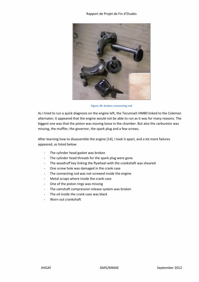
Figure 30: broken connecting rod
As I tried to run a quick diagnosis on the engine left, the Tecumseh HM80 linked to the Coleman
alternator; it appeared that the engine would not be able to run as it was for many reasons. The
biggest one was that the piston was moving loose in the chamber. But also the carburetor was
missing, the muffler, the governor, the spark plug and a few screws.
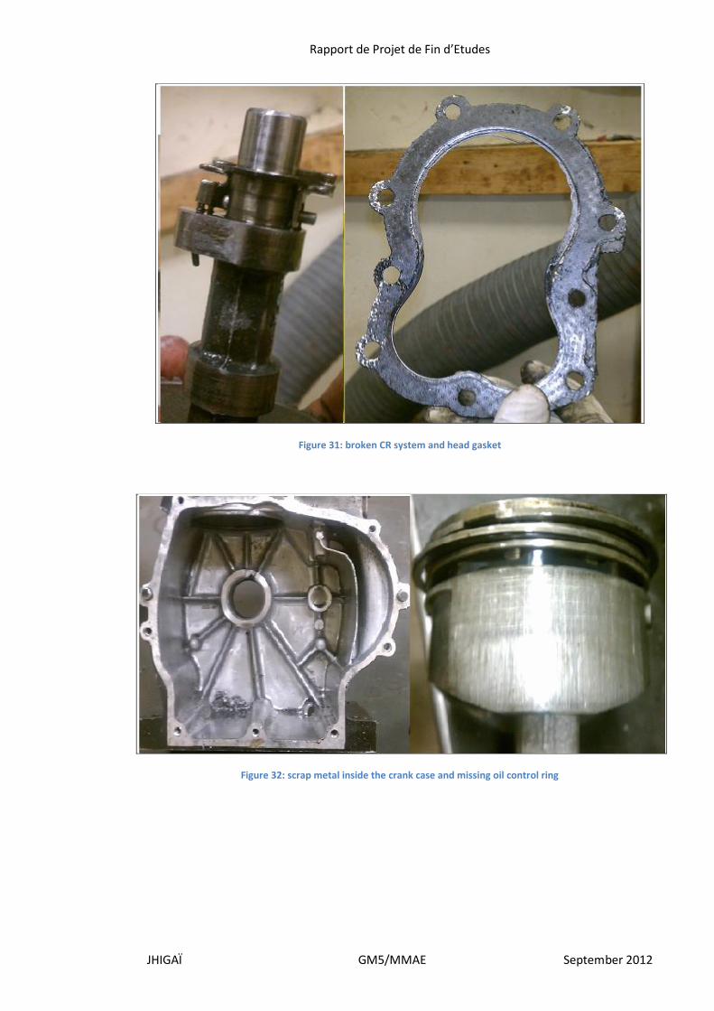
After learning how to disassemble the engine [14], I took it apart, and a lot more failures
appeared, as listed below:
- The cylinder head gasket was broken
- The cylinder head threads for the spark plug were gone
- The woodruff key linking the flywheel with the crankshaft was sheared
- One screw hole was damaged in the crank case
- The connecting rod was not screwed inside the engine
- Metal scraps where inside the crank case
- One of the piston rings was missing
- The camshaft compression release system was broken
- The oil inside the crank case was black
- Worn out crankshaft
Rapport de Projet de Fin d’Etudes
JHIGAÏ GM5/MMAE September 2012
Figure 31: broken CR system and head gasket
Figure 32: scrap metal inside the crank case and missing oil control ring
Rapport de Projet de Fin d’Etudes
JHIGAÏ GM5/MMAE September 2012
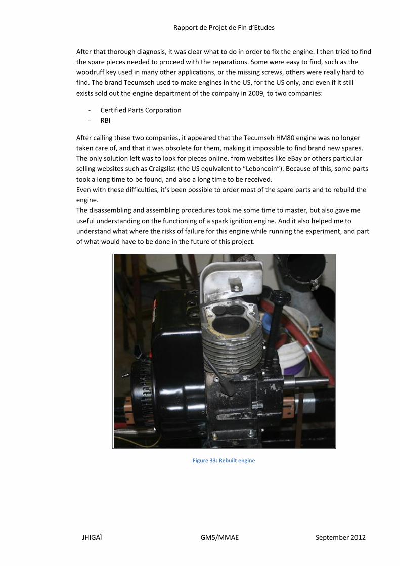
After that thorough diagnosis, it was clear what to do in order to fix the engine. I then tried to find
the spare pieces needed to proceed with the reparations. Some were easy to find, such as the
woodruff key used in many other applications, or the missing screws, others were really hard to
find. The brand Tecumseh used to make engines in the US, for the US only, and even if it still
exists sold out the engine department of the company in 2009, to two companies:
- Certified Parts Corporation
- RBI
After calling these two companies, it appeared that the Tecumseh HM80 engine was no longer
taken care of, and that it was obsolete for them, making it impossible to find brand new spares.
The only solution left was to look for pieces online, from websites like eBay or others particular
selling websites such as Craigslist (the US equivalent to “Leboncoin”). Because of this, some parts
took a long time to be found, and also a long time to be received.
Even with these difficulties, it’s been possible to order most of the spare parts and to rebuild the
engine.
The disassembling and assembling procedures took me some time to master, but also gave me
useful understanding on the functioning of a spark ignition engine. And it also helped me to
understand what where the risks of failure for this engine while running the experiment, and part
of what would have to be done in the future of this project.
Figure 33: Rebuilt engine
Rapport de Projet de Fin d’Etudes
JHIGAÏ GM5/MMAE September 2012
I realized that the time it took me to learn how to handle the engine, and to understand its
functioning could have been spared, or at least reduced if I could have beneficiated from the work
of the previous people who worked on the project, not really in terms of results, because those
where accessible, but in terms of handling and general internal combustion engine knowledge.
I decided then to realize a tutorial explaining how to assemble and disassemble the engine as well
as giving information on the experimental setup, it’s functioning and the evolutions that could be
applied to the engine. By doing this, the next people in charge of leading the project should be
able to progress quicker on the project and get more quickly to the testing.
B. Formation
As I was conducting the project, two people joined my research:
- Abhishek Chandnani, BS in Mechanical and Aerospace engineering
- Cedric Zacarias Ramos Silva, BS in Mechanical and Aerospace engineering
Both freshly had freshly graduated in May from IIT and where looking for an interesting project to
gain a valuable experience for their career. Mr. Ramos Silva joined first in June, and then Mr.
Chandnani in late August.
Thanks to them, the project took a different turn, it was no longer only a project on
Homogeneous Charge Thermal Ignition, but also a team project in which I was the senior
researcher. My tasks also changed as I had to coordinate the new formed team, and of course
teach them everything I could so that they could progress on their own and be really productive
on the project.
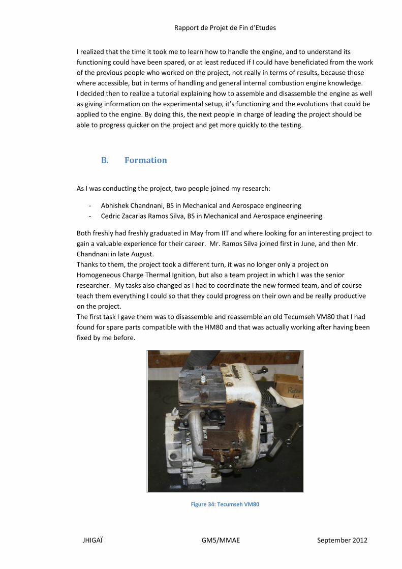
The first task I gave them was to disassemble and reassemble an old Tecumseh VM80 that I had
found for spare parts compatible with the HM80 and that was actually working after having been
fixed by me before.
Figure 34: Tecumseh VM80
Rapport de Projet de Fin d’Etudes
JHIGAÏ GM5/MMAE September 2012
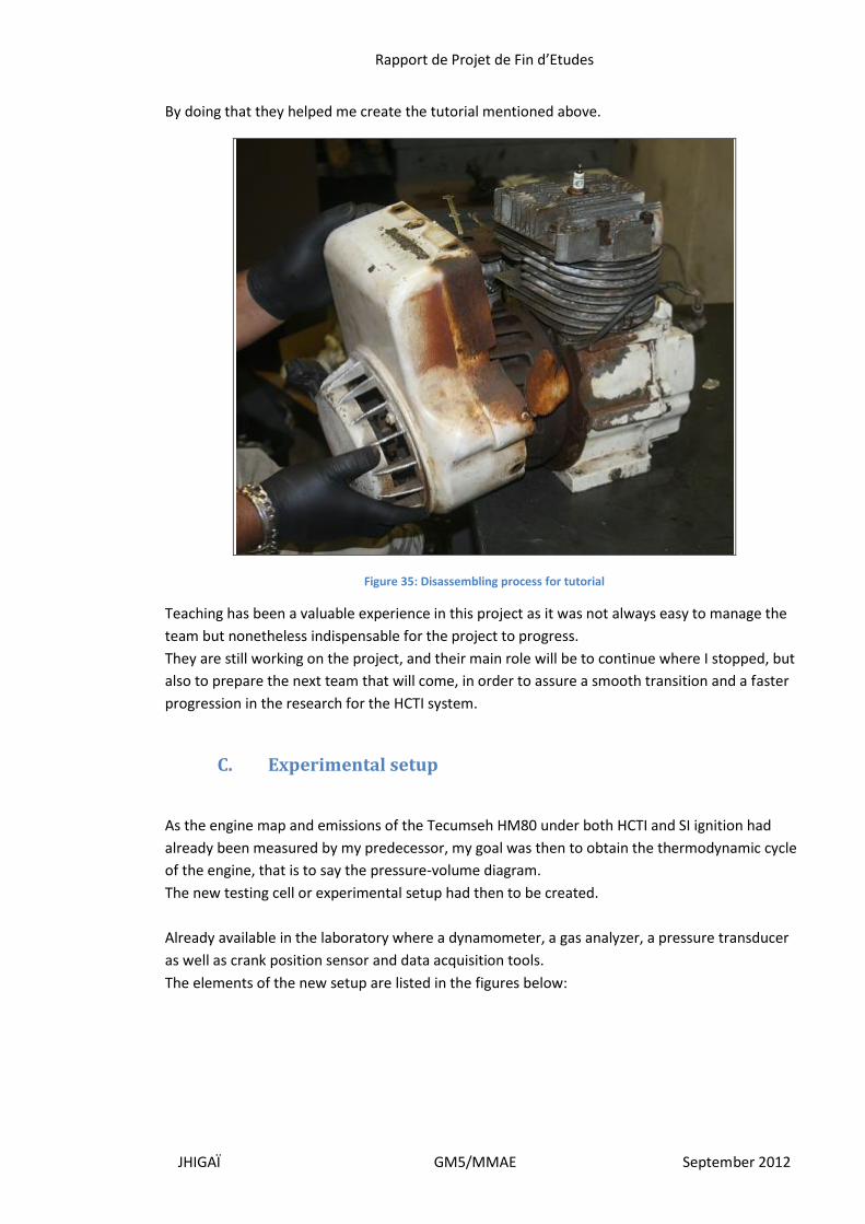
By doing that they helped me create the tutorial mentioned above.
Figure 35: Disassembling process for tutorial
Teaching has been a valuable experience in this project as it was not always easy to manage the
team but nonetheless indispensable for the project to progress.
They are still working on the project, and their main role will be to continue where I stopped, but
also to prepare the next team that will come, in order to assure a smooth transition and a faster
progression in the research for the HCTI system.
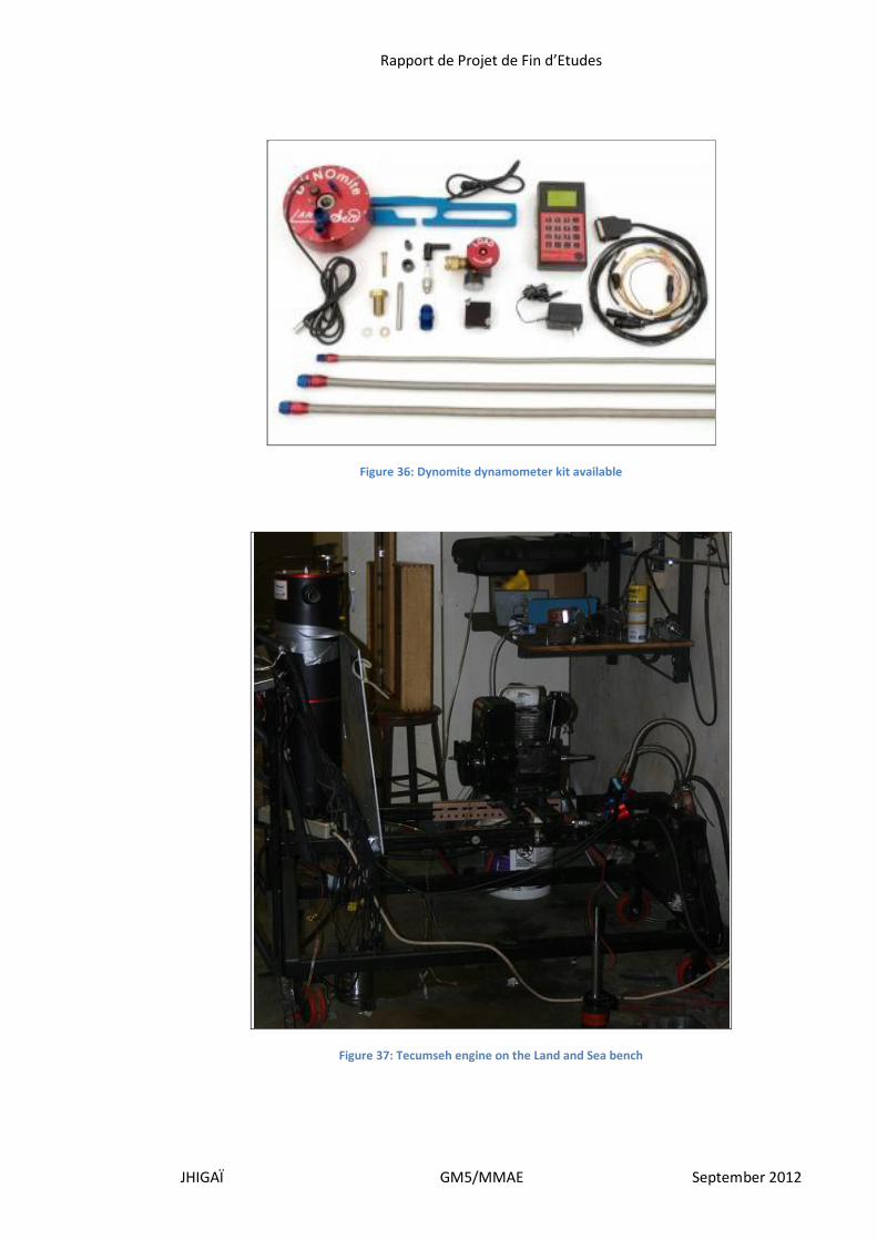
C. Experimental setup
As the engine map and emissions of the Tecumseh HM80 under both HCTI and SI ignition had
already been measured by my predecessor, my goal was then to obtain the thermodynamic cycle
of the engine, that is to say the pressure-volume diagram.
The new testing cell or experimental setup had then to be created.
Already available in the laboratory where a dynamometer, a gas analyzer, a pressure transducer
as well as crank position sensor and data acquisition tools.
The elements of the new setup are listed in the figures below:
Rapport de Projet de Fin d’Etudes
JHIGAÏ GM5/MMAE September 2012
Figure 36: Dynomite dynamometer kit available
Figure 37: Tecumseh engine on the Land and Sea bench

Rapport de Projet de Fin d’Etudes
JHIGAÏ GM5/MMAE September 2012
Figure 38: PLC amplifier and National Instruments analog interface device
Figure 39: QSB4 Digital interface, with analog input, encoder input, power inlet and usb data output
Figure 40: Bench control dash with accelerator, console/interface and load valve
Rapport de Projet de Fin d’Etudes
JHIGAÏ GM5/MMAE September 2012
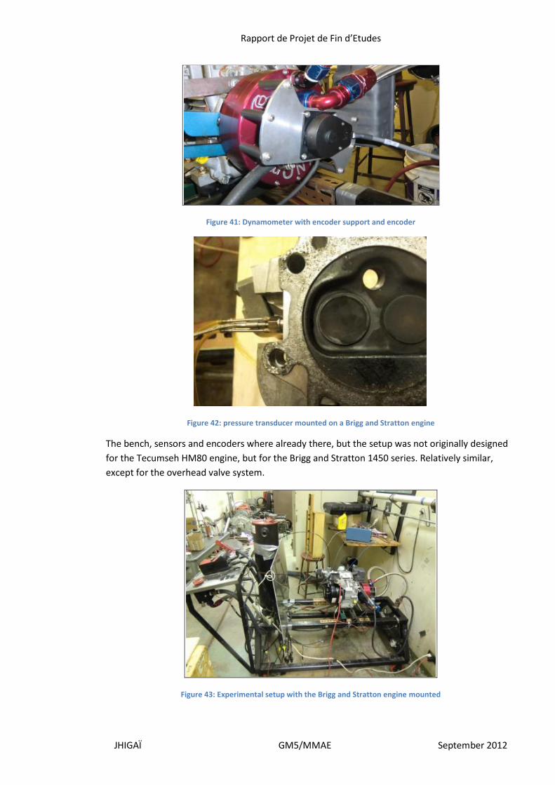
Figure 41: Dynamometer with encoder support and encoder
Figure 42: pressure transducer mounted on a Brigg and Stratton engine
The bench, sensors and encoders where already there, but the setup was not originally designed
for the Tecumseh HM80 engine, but for the Brigg and Stratton 1450 series. Relatively similar,
except for the overhead valve system.
Figure 43: Experimental setup with the Brigg and Stratton engine mounted
Rapport de Projet de Fin d’Etudes
JHIGAÏ GM5/MMAE September 2012
Even though both engines were similar, many modifications had to be made in order to adapt the
engine to the cell:
- Modification of the cylinder head in order for the pressure transducer to fit
- Modification to the bench itself for the engine to fit
- Creation of a fixation system to hold the dynamometer
- Creation of a new crankshaft to fit the dynamometer
- Creation of a adapter to match the mounted carburetor to the accelerator
- Or creation of a new accelerator
- Design of new keys to lock the new shaft in the dynamometer
Those modifications are still being done at the lab due to the time necessary for these operations
to be made. They are conducted by Mr. Chandnani and Mr. Ramos Silva with the help of Mr.
Johnson and should be finished by mid September.
The shaft was the biggest issue with adapting the Tecumseh engine on the bench. Unlike Brigg
and Stratton who makes factory shafts to fit dynamometers like the Land and Sea Dynomite
available in the laboratory, Tecumseh does not make any. They don’t even sell parts anymore.
The new shaft had to be cut directly using a spare shaft too big for the dynamometer, with the
risk of weakening the shaft, weakening that could later lead to rupture during the experiment.
Modifying the shaft implied to make custom keys also to lock it inside the dynamometer.
One of the concerns with the shaft is that a direct coupling with the dynamometer will result in a
lot of vibrations, since there’s no way to center the axis of the dynamometer with the axis of the
crankshaft. A solution could be to use a rubber coupling, but as a result, the crank angle sensor
would not give accurate results anymore due to the relative movement of the rubber damp.
It’s been decided to try with the modified shaft.
When contacting Land and Sea for technical assistance, we have been told that these
dynamometers where really old and that they could not really be of any help regarding our
application.
Unfortunately, due to various reasons, it has not been possible yet to use the testing cell with the
Tecumseh engine in order to complete the previous work of Mr. Chandrasekhar.
One of the reasons is that the testing cell was already used by another team also working on the
HCTI System. This team was composed of:
- Juan I Domenech, MS in Mechanical and Aerospace Engineering at IIT
- Alejandro Assens Blanch, MS in Mechanical and Aerospace Engineering at IIT
Both exchange students from Spain.
They conducted their experiments until August 15th and it has not been possible before their
departure to try the testing cell. As a matter of fact, the custom-made aspect of the bench made
it almost impossible for them to dismount their engine until it broke.
Still, both engines were similar in size and horse power, so the results can be expected in a first
approach to be similar also. I’ve been graciously authorized to use some of their results as models
for this report.
Rapport de Projet de Fin d’Etudes
JHIGAÏ GM5/MMAE September 2012
IV. Data representation
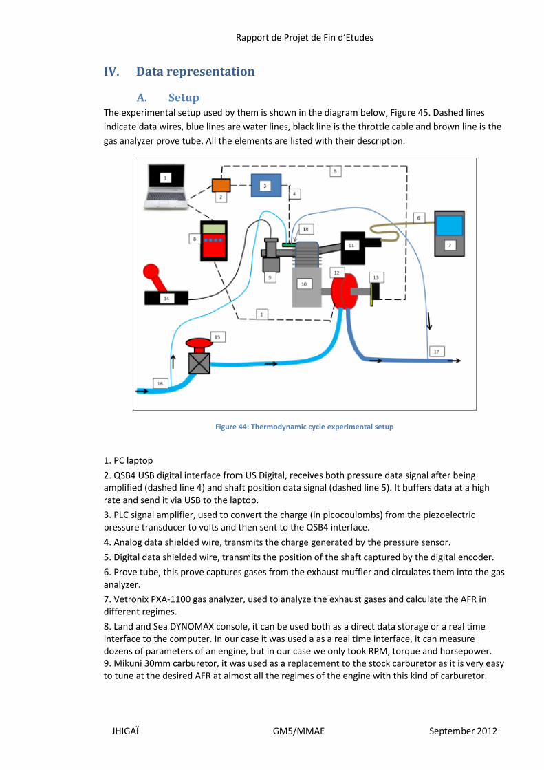
A. Setup The experimental setup used by them is shown in the diagram below, Figure 45. Dashed lines
indicate data wires, blue lines are water lines, black line is the throttle cable and brown line is the
gas analyzer prove tube. All the elements are listed with their description.
Figure 44: Thermodynamic cycle experimental setup
1. PC laptop
2. QSB4 USB digital interface from US Digital, receives both pressure data signal after being amplified (dashed line 4) and shaft position data signal (dashed line 5). It buffers data at a high rate and send it via USB to the laptop.
3. PLC signal amplifier, used to convert the charge (in picocoulombs) from the piezoelectric pressure transducer to volts and then sent to the QSB4 interface.
4. Analog data shielded wire, transmits the charge generated by the pressure sensor.
5. Digital data shielded wire, transmits the position of the shaft captured by the digital encoder.
6. Prove tube, this prove captures gases from the exhaust muffler and circulates them into the gas analyzer.
7. Vetronix PXA-1100 gas analyzer, used to analyze the exhaust gases and calculate the AFR in different regimes.
8. Land and Sea DYNOMAX console, it can be used both as a direct data storage or a real time interface to the computer. In our case it was used a as a real time interface, it can measure dozens of parameters of an engine, but in our case we only took RPM, torque and horsepower. 9. Mikuni 30mm carburetor, it was used as a replacement to the stock carburetor as it is very easy to tune at the desired AFR at almost all the regimes of the engine with this kind of carburetor.
Rapport de Projet de Fin d’Etudes
JHIGAÏ GM5/MMAE September 2012
10. Briggs & Stratton 1450 series engine, 305cc engine with OHV head design and 14.5 maximum raw torque (more information about the engine found in the appendix).
11. Muffler, the outlet port has been specially modified to allow EGR so that the combustion is more complete and the missions are lowered, more on that later.
12. Land and Sea water brake, with inbuilt RPM sensor and torque sensor, directly coupled to the 1" engine output shaft with keyway.
13. US Digital H6 digital encoder with 2 channels and index channel, resolution of 2500 cycles per revolution.
14. Hand throttle assembly.
15. Water brake pressure regulator, used to increase or decrease the load on the engine trough the water brake.
16. Fresh water inlet, the circuit bifurcates to a second smaller line to cool the pressure transducer, the main stream is used to induce a load in the water brake.
17. Used water outlet to drain.
18. Kistler 6014A pressure transducer, piezoelectric type, induces a charge when a deformation in the measuring membrane occurs, translating it to pressure.
Their system was entirely built from zero at the beginning of the project, custom parts had to be
designed and built or machined by third parties.
Since their engine was brand new, they had to redo all the tests about the engine mapping and
emissions analysis, those were pretty similar to the one obtained with the Tecumseh engine and
we are only interested in the thermodynamic cycle they were able to obtain.
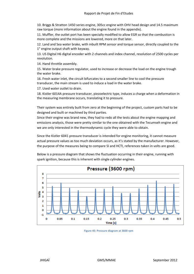
Since the Kistler 6041 pressure transducer is intended for engine monitoring, it cannot measure
actual pressure values as too much deviation occurs, as it’s stated by the manufacturer. However,
the purpose of the measures being to compare SI and HCTI, references taken in volts are good.
Below is a pressure diagram that shows the fluctuation occurring in their engine, running with
spark ignition, because this is inherent with single cylinder engines.
Figure 45: Pressure diagram at 3600 rpm
Rapport de Projet de Fin d’Etudes
JHIGAÏ GM5/MMAE September 2012
B. Design
The Brigg & Stratton engine also had to be modified to be able to run in HCTI mode, but unlike the
Tecumseh engine, none of the designs tried could improve the efficiency of the HCTI mode
compared to the SI mode.
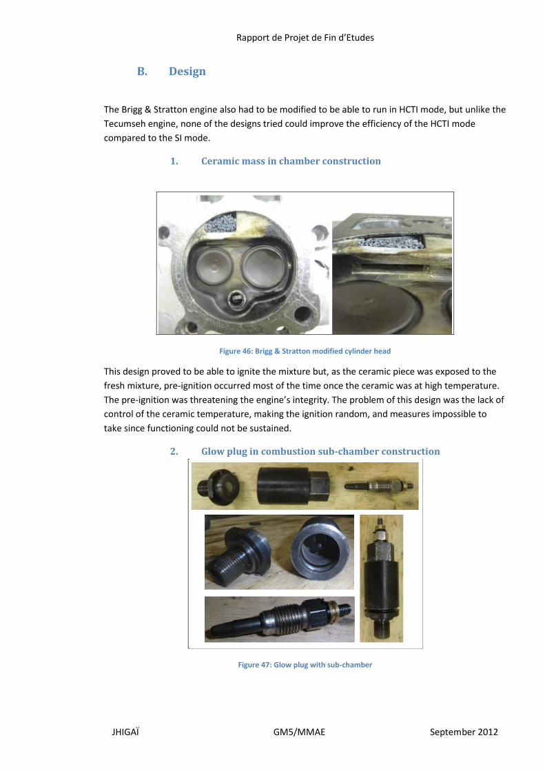
1. Ceramic mass in chamber construction
Figure 46: Brigg & Stratton modified cylinder head
This design proved to be able to ignite the mixture but, as the ceramic piece was exposed to the
fresh mixture, pre-ignition occurred most of the time once the ceramic was at high temperature.
The pre-ignition was threatening the engine’s integrity. The problem of this design was the lack of
control of the ceramic temperature, making the ignition random, and measures impossible to
take since functioning could not be sustained.
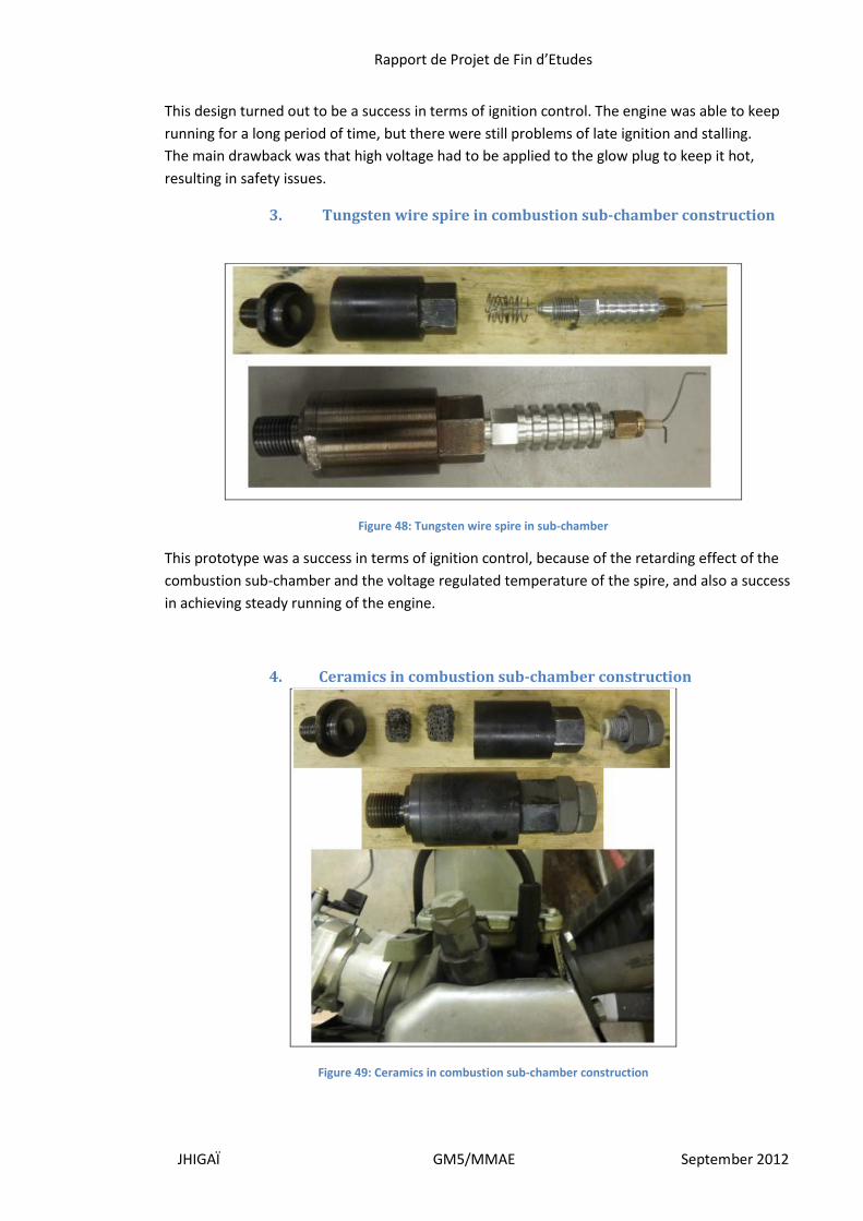
2. Glow plug in combustion sub-chamber construction
Figure 47: Glow plug with sub-chamber
Rapport de Projet de Fin d’Etudes
JHIGAÏ GM5/MMAE September 2012
This design turned out to be a success in terms of ignition control. The engine was able to keep
running for a long period of time, but there were still problems of late ignition and stalling.
The main drawback was that high voltage had to be applied to the glow plug to keep it hot,
resulting in safety issues.
3. Tungsten wire spire in combustion sub-chamber construction
Figure 48: Tungsten wire spire in sub-chamber
This prototype was a success in terms of ignition control, because of the retarding effect of the
combustion sub-chamber and the voltage regulated temperature of the spire, and also a success
in achieving steady running of the engine.
4. Ceramics in combustion sub-chamber construction
Figure 49: Ceramics in combustion sub-chamber construction
Rapport de Projet de Fin d’Etudes
JHIGAÏ GM5/MMAE September 2012
This last design proved to have the best performance compared to the other ones mentioned.
Ignition timing was reliable and the ignition timing was relatively good and accurate. However,
the drawback of this design is the lack of power compared to the SI version. It could not deliver
half of the SI output.
C. Data collected
1. Tungsten wire spire pressure graphs
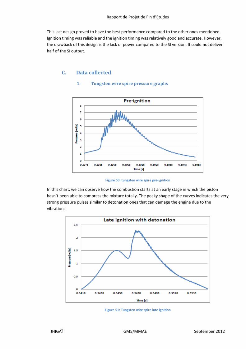
Figure 50: tungsten wire spire pre-ignition
In this chart, we can observe how the combustion starts at an early stage in which the piston
hasn’t been able to compress the mixture totally. The peaky shape of the curves indicates the very
strong pressure pulses similar to detonation ones that can damage the engine due to the
vibrations.
Figure 51: Tungsten wire spire late ignition
Rapport de Projet de Fin d’Etudes
JHIGAÏ GM5/MMAE September 2012
Here we can observe both late ignition and detonation phenomena. Late ignition is clear as the
pressure of the cylinder drops as the piston travels downward and then a second peak of pressure
develops as mixture is ignited. This gives a very low power output.
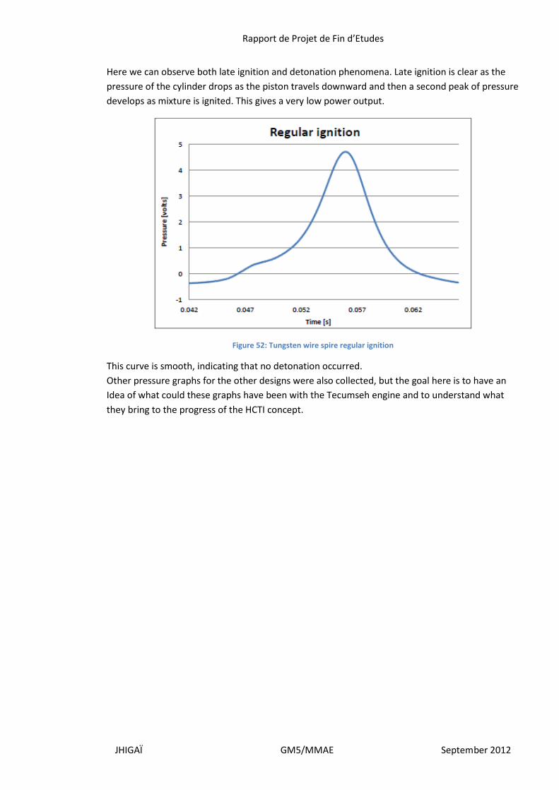
Figure 52: Tungsten wire spire regular ignition
This curve is smooth, indicating that no detonation occurred.
Other pressure graphs for the other designs were also collected, but the goal here is to have an
Idea of what could these graphs have been with the Tecumseh engine and to understand what
they bring to the progress of the HCTI concept.
Rapport de Projet de Fin d’Etudes
JHIGAÏ GM5/MMAE September 2012
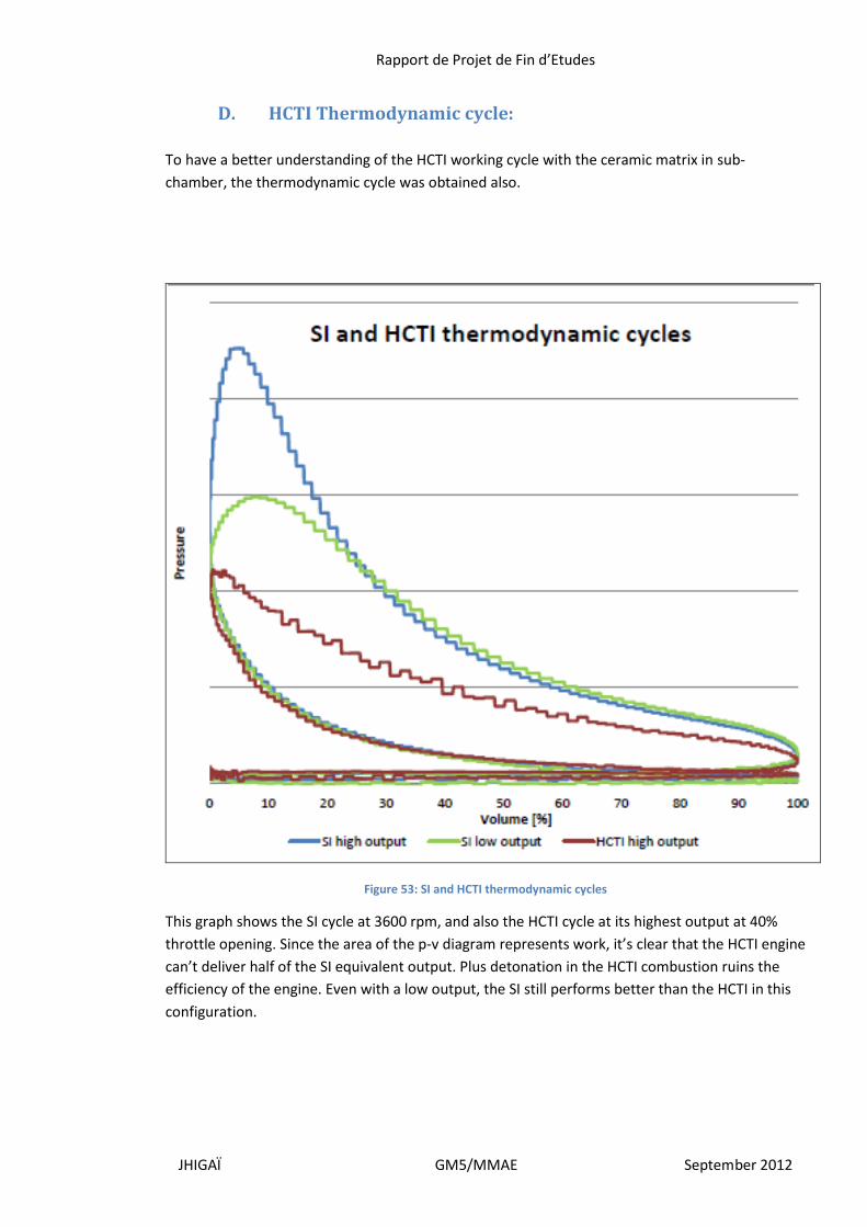
D. HCTI Thermodynamic cycle:
To have a better understanding of the HCTI working cycle with the ceramic matrix in sub-
chamber, the thermodynamic cycle was obtained also.
Figure 53: SI and HCTI thermodynamic cycles
This graph shows the SI cycle at 3600 rpm, and also the HCTI cycle at its highest output at 40%
throttle opening. Since the area of the p-v diagram represents work, it’s clear that the HCTI engine
can’t deliver half of the SI equivalent output. Plus detonation in the HCTI combustion ruins the
efficiency of the engine. Even with a low output, the SI still performs better than the HCTI in this
configuration.
Rapport de Projet de Fin d’Etudes
JHIGAÏ GM5/MMAE September 2012
V. Conclusions and Recommendation
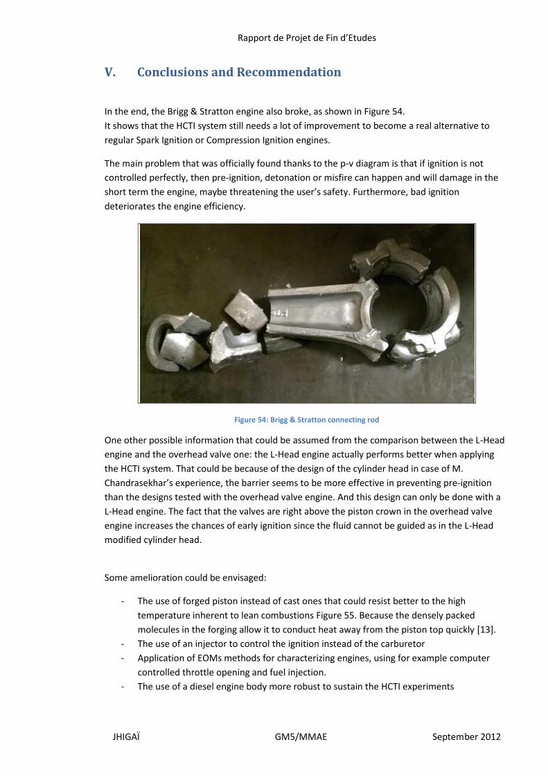
In the end, the Brigg & Stratton engine also broke, as shown in Figure 54.
It shows that the HCTI system still needs a lot of improvement to become a real alternative to
regular Spark Ignition or Compression Ignition engines.
The main problem that was officially found thanks to the p-v diagram is that if ignition is not
controlled perfectly, then pre-ignition, detonation or misfire can happen and will damage in the
short term the engine, maybe threatening the user’s safety. Furthermore, bad ignition
deteriorates the engine efficiency.
Figure 54: Brigg & Stratton connecting rod
One other possible information that could be assumed from the comparison between the L-Head
engine and the overhead valve one: the L-Head engine actually performs better when applying
the HCTI system. That could be because of the design of the cylinder head in case of M.
Chandrasekhar’s experience, the barrier seems to be more effective in preventing pre-ignition
than the designs tested with the overhead valve engine. And this design can only be done with a
L-Head engine. The fact that the valves are right above the piston crown in the overhead valve
engine increases the chances of early ignition since the fluid cannot be guided as in the L-Head
modified cylinder head.
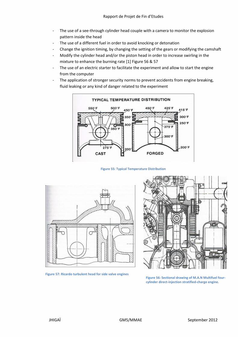
Some amelioration could be envisaged:
- The use of forged piston instead of cast ones that could resist better to the high
temperature inherent to lean combustions Figure 55. Because the densely packed
molecules in the forging allow it to conduct heat away from the piston top quickly [13].
- The use of an injector to control the ignition instead of the carburetor
- Application of EOMs methods for characterizing engines, using for example computer
controlled throttle opening and fuel injection.
- The use of a diesel engine body more robust to sustain the HCTI experiments
Rapport de Projet de Fin d’Etudes
JHIGAÏ GM5/MMAE September 2012
- The use of a see-through cylinder head couple with a camera to monitor the explosion
pattern inside the head
- The use of a different fuel in order to avoid knocking or detonation
- Change the ignition timing, by changing the setting of the gears or modifying the camshaft
- Modify the cylinder head and/or the piston head in order to increase swirling in the
mixture to enhance the burning rate [1] Figure 56 & 57
- The use of an electric starter to facilitate the experiment and allow to start the engine
from the computer
- The application of stronger security norms to prevent accidents from engine breaking,
fluid leaking or any kind of danger related to the experiment
Figure 55: Typical Temperature Distribution
Figure 57: Ricardo turbulent head for side valve engines
Figure 56: Sectional drawing of M.A.N Multifuel four-cylinder direct-injection stratified-charge engine.

Rapport de Projet de Fin d’Etudes
JHIGAÏ GM5/MMAE September 2012
One thing important also is the transmission of the data gathered. It took at least two months for
Mr. Domenech to learn to program Labview in order to process the data acquired, and it will
probably take the same amount of time to the next group that will try to obtain the
thermodynamic cycle. It would facilitate the project progression to transmit these methods from
one group to the next one.
Finally, theoretically speaking, HCTI is still very promising. Efforts have to be made in the data
gathering and experimental setup in order to draw out the full potential of this system.
Rapport de Projet de Fin d’Etudes
JHIGAÏ GM5/MMAE September 2012
VI. Figures
Figure 1: Combustion in spark ignition engine […] ............................................................................. 8
Figure 2: SI engine emissions at various air-fuel ratios [...] ................................................................ 8
Figure 3: smart plug [10] ..................................................................................................................... 9
Figure 4: L-head engine [9] ............................................................................................................... 10
Figure 5: Porous Ceramic mass installed in the cylinder head [10] .................................................. 11
Figure 6: CAD model of experimental head [10] .............................................................................. 11
Figure 7: Working cycle of HCTI and SI four stroke engines [9] ........................................................ 12
Figure 8: Engine specifications .......................................................................................................... 13
Figure 9: Engine and alternator with modified head ........................................................................ 14
Figure 10: Alternator specifications .................................................................................................. 14
Figure 11: Float and Diaphragm type tecumseh carburetors ........................................................... 15
Figure 12: Air tank and flow meter ................................................................................................... 15
Figure 13: Water Rheostat and electric circuit ................................................................................. 16
Figure 14: Water Rheostat and transformer specifications .............................................................. 16
Figure 15: Gas analyzer specifications .............................................................................................. 16
Figure 16: Gas analyzer ..................................................................................................................... 17
Figure 17: Schematic of the engine test cell ..................................................................................... 17
Figure 18: Engine efficiency map of SI engine- Stoichiometric AFR (13.5:1) .................................... 18
Figure 19: Engine efficiency map of SI engine-Leanest AFR (17:1) ................................................... 19
Figure 20: Efficiency map of HCTI engine at 17:1 (AFR) .................................................................... 19
Figure 21: Comparison of brake thermal efficiency at 3600 RPM .................................................... 20
Figure 22: Engine efficiency map of HCTI engine - 18:1 (AFR) .......................................................... 20
Figure 23: Engine efficiency map of HCTI engine - 20:1 (AFR) .......................................................... 21
Figure 24: Carbon monoxide emissions for SI and HCTI engine at 3600 RPM .................................. 21
Figure 25: Carbon dioxide emissions for SI and HCTI engine at 3600 RPM ...................................... 22
Figure 26: Hydrocarbon emission for SI and HCTI engine at 3600 RPM ........................................... 22
Figure 27: Nox emissions for SI and HCTI engines at 3600 RPM ...................................................... 23
Figure 28: Crank position and angle VS Pressure of a SI engine example ........................................ 24
Figure 29: Blown-up Tecumseh crank case ....................................................................................... 25
Figure 30: broken connecting rod ..................................................................................................... 26
Figure 31: broken CR system and head gasket ................................................................................. 27
Figure 32: scrap metal inside the crank case and missing oil control ring ....................................... 27
Figure 33: Rebuilt engine .................................................................................................................. 28
Figure 34: Tecumseh VM80 .............................................................................................................. 29
Figure 35: Disassembling process for tutorial ................................................................................... 30
Figure 36: Dynomite dynamometer kit available ............................................................................. 31
Figure 37: Tecumseh engine on the Land and Sea bench................................................................. 31
Figure 38: PLC amplifier and National Instruments analog interface device.................................... 32
Rapport de Projet de Fin d’Etudes
JHIGAÏ GM5/MMAE September 2012
Figure 39: QSB4 Digital interface, with analog input, encoder input, power inlet and usb data
output ............................................................................................................................................... 32
Figure 40: Bench control dash with accelerator, console/interface and load valve ........................ 32
Figure 41: Dynamometer with encoder support and encoder ......................................................... 33
Figure 42: pressure transducer mounted on a Brigg and Stratton engine ....................................... 33
Figure 43: Experimental setup with the Brigg and Stratton engine mounted .................................. 33
Figure 44: Thermodynamic cycle experimental setup ...................................................................... 35
Figure 45: Pressure diagram at 3600 rpm ......................................................................................... 36
Figure 46: Brigg & Stratton modified cylinder head ......................................................................... 37
Figure 47: Glow plug with sub-chamber ........................................................................................... 37
Figure 48: Tungsten wire spire in sub-chamber ............................................................................... 38
Figure 49: Ceramics in combustion sub-chamber construction ....................................................... 38
Figure 50: tungsten wire spire pre-ignition ...................................................................................... 39
Figure 51: Tungsten wire spire late ignition ..................................................................................... 39
Figure 52: Tungsten wire spire regular ignition ................................................................................ 40
Figure 53: SI and HCTI thermodynamic cycles .................................................................................. 41
Figure 54: Brigg & Stratton connecting rod ...................................................................................... 42
Figure 55: Typical Temperature Distribution .................................................................................... 43
Figure 57: Ricardo turbulent head for side valve engines ................................................................ 43
Figure 56: Sectional drawing of M.A.N Multifuel four-cylinder direct-injection stratified-charge
engine. .............................................................................................................................................. 43
Rapport de Projet de Fin d’Etudes
JHIGAÏ GM5/MMAE September 2012
Bibliography
[1] Internal combustion engines fundamentals. New York: McGraw-Hill, 1988. Print
[2] M, Stockinger, Schäpertöns H, and Kuhlmann P. “Versuche an einem gemischansugenden
Verbrennungsmotor mot Selbstzündning.” MTZ motortechnische Zeitschrift 53.2 (1992): 80-85.
Abstract. International journal of vehicle design 44.1/2 (2007) Print.
[3] “Homogeneous charge compression ignition” Wikipedia, the free encyclopedia. Web 17
Oct.2009. <http://en.wikipedia.org/wiki/Homogeneous_charge_compression_ignition>
[4] Johansson, Bengt, “Homogeneous charge compression ignition: The future of IC engines?”
International journal of vehicle design 44.1/2 (2007): 1-19. Print
[5] Taylor, Charles F. The internal combustion engine in theory and practice. Vol. 2. Cambridge:
MIT, 1985. Print
[6] Introduction to Internal Combustion Engines. Warrendale : Society of Automotive Engineers,
1999. Print
[7] Robison, William. Gas and petroleum engines: A practical treatise on the internal combustion
engines. London: E. & F. N. Spon, 1890. Print
[8] “New Technology Sparks Smoother Engines and Cleaner Air.” Scientific and technical
information. NASA. Web. 12 Aug. 2009.
<http://www.sti.nasa.gov/tto/spinoff2001/t1.html>
[9] Tecumseh technician’s handbook- 3 to 11Hp 4-cycle L head engines. Print
[10] Donyboy, the small engine doctor.Web, youtube channel.
<http://www.youtube.com/user/donyboy73/videos?sort=dd&query=tecumseh&flow=grid&view=
0&page=3>
[12] TecumsehL-head engines Service repair maintenance. Overland Park, Kansas. Clymer, 2006.
[13] Rick Voegelin The step-by-step guide to Engine Blueprinting pratical methods for racing and
rebuilding.North Branch, MN:CarTech, 2005. Print
[14] Tom Monroe Engine Builder’s Handbook how to rebuild your engine to original or improved
condition.New York, HPBooks, 1996. Print.
[15] Greg Banish Engine Management Advanced Tuning.North Branch, MN:CarTech, 2005. Print

Rapport de Projet de Fin d’Etudes
JHIGAÏ GM5/MMAE September 2012

Rapport de Projet de Fin d’Etudes
JHIGAÏ GM5/MMAE September 2012
Appendixes
A. Calculations
Calculation of air flow rate:
From Bernoulli’s equation,
p1 + ½ v1 + gz1 = p2 + ½ v2 + gz2
p1 - Air pressure at inlet [pa], atmospheric pressure.
- Density of air [kg/m3].
v1 - Velocity of air at inlet [m/s], assumed as zero.
g - Acceleration due to gravity, 9.81 m/s2
z1 - Height of inlet from reference point [m].
p2 - Air pressure at outlet [pa].
v2 - Velocity of air at outlet [m/s]
z2 - Height of outlet from reference point [m].
The difference between gravity terms in the Bernoulli’s equation is very negligible. Hence the
equation becomes,
p1 - p2 = ½ v2
v2 = [2(p1 - p2)/] ½

Rapport de Projet de Fin d’Etudes
JHIGAÏ GM5/MMAE September 2012
From continuity equation,
A1v1 = A2v2
A1 - Cross sectional area of inlet [m2].
A2 - Cross sectional area of outlet [m2].
Mass flow rate of air, mair
mair = A2v2 =A2 [2(p1 - p2)/] ½
Calculation of fuel consumption rate:
Time for 10 cc of fuel consumption - t [s]
Fuel consumption rate in volume, f [cc/s]
f = 10/t
Fuel consumption rate, mfuel [kg/s]
mfuel = f x fuel /1000
fuel - Density of fuel [kg/m3]
Energy supplied:
E = mfuel x CV
CV - Calorific value of the fuel, for gasoline calorific value is 47,300-kJ/ kg
Calculation of power and torque:
Since electric load is applied during the experiment, electric power is calculated using joules law.
Rapport de Projet de Fin d’Etudes
JHIGAÏ GM5/MMAE September 2012
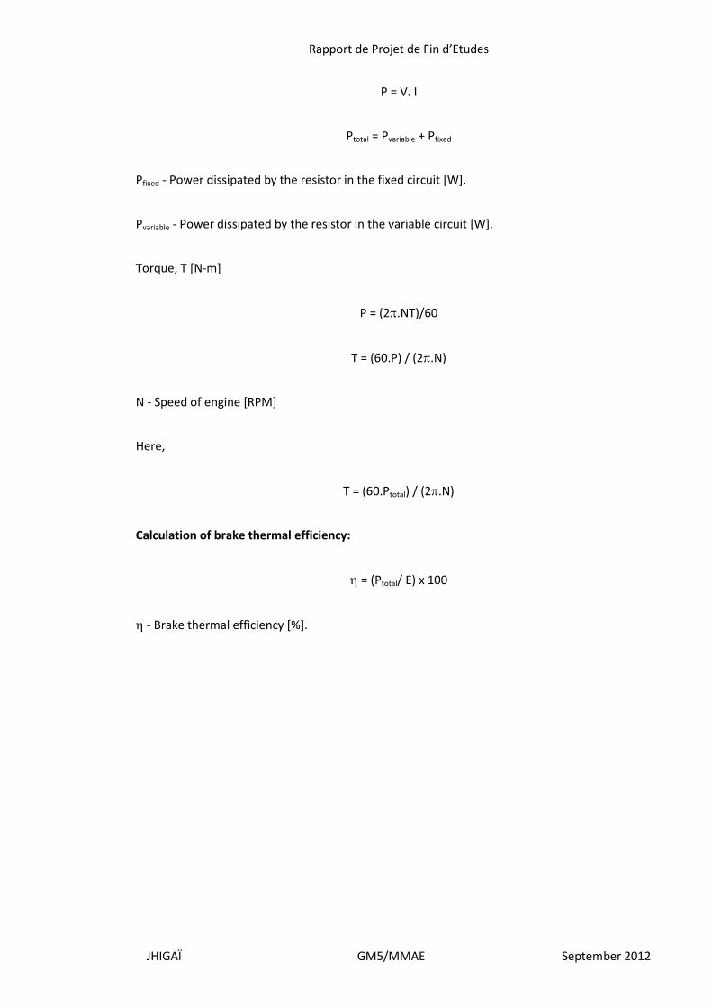
P = V. I
Ptotal = Pvariable + Pfixed
Pfixed - Power dissipated by the resistor in the fixed circuit [W].
Pvariable - Power dissipated by the resistor in the variable circuit [W].
Torque, T [N-m]
P = (2.NT)/60
T = (60.P) / (2.N)
N - Speed of engine [RPM]
Here,
T = (60.Ptotal) / (2.N)
Calculation of brake thermal efficiency:
= (Ptotal/ E) x 100
- Brake thermal efficiency [%].
Rapport de Projet de Fin d’Etudes
JHIGAÏ GM5/MMAE September 2012
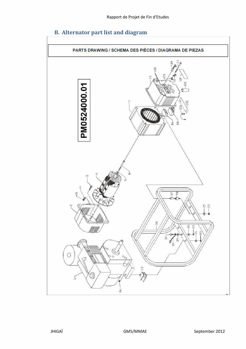
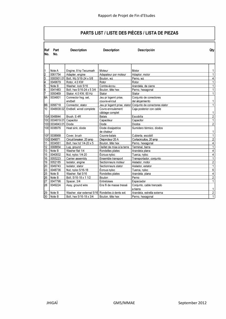
B. Alternator part list and diagram
Rapport de Projet de Fin d’Etudes
JHIGAÏ GM5/MMAE September 2012
Rapport de Projet de Fin d’Etudes
JHIGAÏ GM5/MMAE September 2012
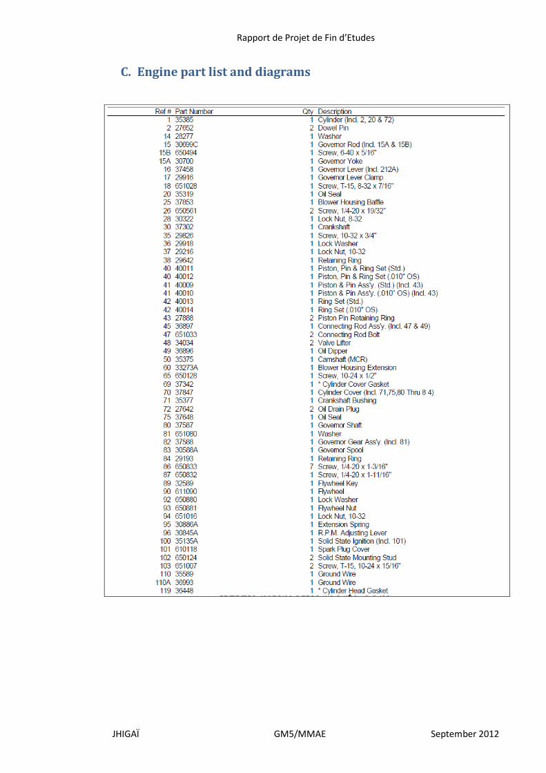
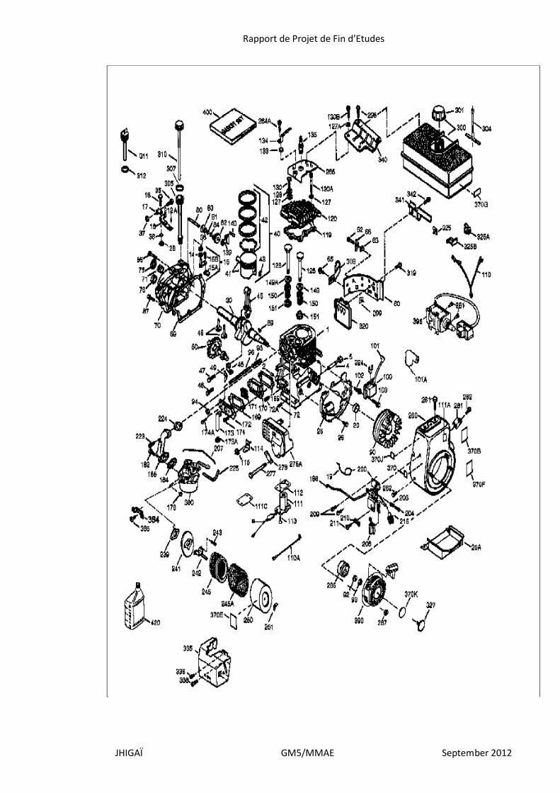
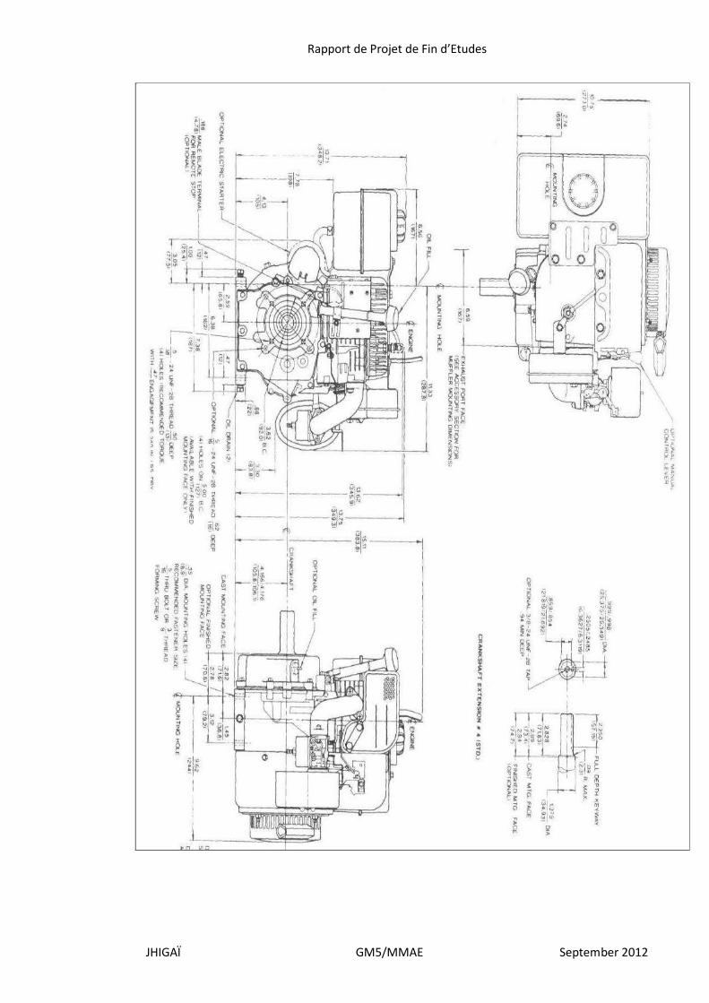
C. Engine part list and diagrams

Rapport de Projet de Fin d’Etudes
JHIGAÏ GM5/MMAE September 2012
Rapport de Projet de Fin d’Etudes
JHIGAÏ GM5/MMAE September 2012
Rapport de Projet de Fin d’Etudes
JHIGAÏ GM5/MMAE September 2012
Rapport de Projet de Fin d’Etudes
JHIGAÏ GM5/MMAE September 2012
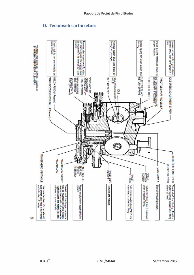
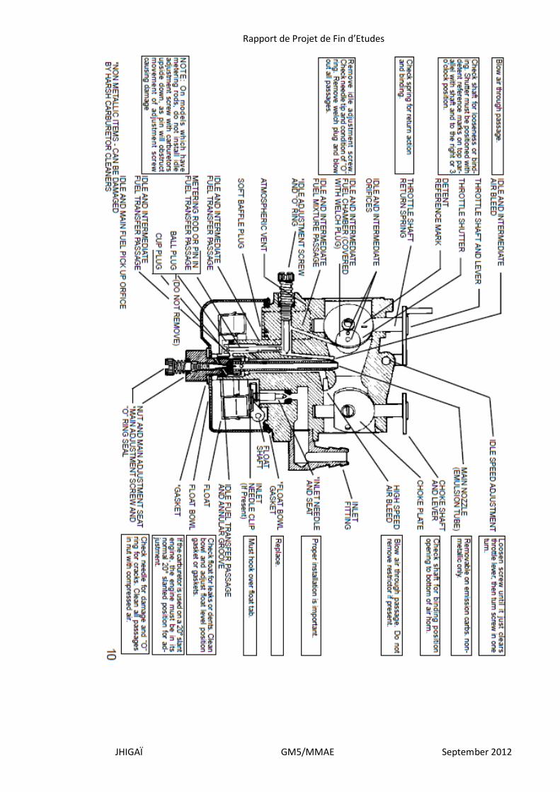
D. Tecumseh carburetors
Rapport de Projet de Fin d’Etudes
JHIGAÏ GM5/MMAE September 2012