Embed Size (px)
Citation preview
512Colloque International Sols Non Saturés et Environnement « UNSATlemcen09 »
Tlemcen, 27 et 28 Octobre 2009
Landfill drainage with geocomposites
Rabah Arab* — Farid Cherifi** — Fayçal Loudjani***
*AFITEX France, 13 -15 rue Louis Blériot Champhol F28300, [email protected]
**AFITEX Algérie Spa, cité des Castors villa N°. 150 C Bordj El Kiffan Algérie, afitex-algé[email protected]
*** Général Environnement, [email protected]
ABSTRACT. The authors present three case histories Waste Landfill (WL) drainage systems using geocomposite. The first is used for the bottom of the landfill to replace partially the gravel layer. The second is used for drainage of leachate and water on slope and the last one is used for capping system drainage. The design method is also presented
RÉSUMÉ. Les auteurs présentent trois cas de drainage par géocomposite dans les centres de stockage de déchets. Le premier concerne le drainage de fond en substitution partielle de la couche granulaire. Le second cas traite du drainage en talus et le dernier du drainage de couverture. La méthode de dimensionnement est également présentéeKEYWORDS: landfill, drainage, geocomposites, design.MOTS-CLÉS : centre de stockage de déchets, drainage, géocomposites, dimensionnement
513
Colloque International Sols Non Saturés et Environnement UNSATlemcen09
1. Introduction
Nowadays, drainage geocomposites are widely used in waste landfills management, particularly in capping system and on slopes. The most of the landfill capping systems contain in their structure a drainage system, particularly in semi permeable capping. The function of the drainage is to limit the infiltration of water inside the landfill. The last decade we developed a geocomposite which assures simultaneously the drainage and the waterproofing of the landfill capping. This solution was applied in several landfills capping system. Another application is the drainage on slope. Traditionally, we use a coarse material, now days we use a drainage géocomposite witch is resistant to UV rays and assures also the protection of the liner. This solution is widely used in Western European and in North Africa. We also developed another application witch concern the partially substitution of the granular layer drainage at the bottom. The drainage geocomposites need to be designed taking into account all the project characteristics. For this purpose, we use Lymphea Software (Arab and al. 2002). In our communication, we will present threecase histories dealing with bottom, capping and slope drainage. We will also present how the design is conducted with Lymphea software.
2. Partial substitution of the granular layer at the bottom of landfill
The partially substitution of the gravel layer with geocomposite at the bottom of landfill sites allows to save granular materials that are more and more difficult to find and lead to important delivery costs. For environmental purposes, it also allows optimisation of the storage capacity of the cell and reduction of truck traffic. The design of the geocomposite has to be realised specifically for this type of application because the geocomposite will be under high pressures and in an aggressive environment due to leachate. In France, the legislation for Landfill Waste Storage (LWS) defines the leachate collector system at the bottom of the cell as a granular layer with collector pipes. The thickness of the granular layer is 0.50 m with a coefficient of permeability not less than 10-4 m/s. The admissible maximum height of leachate at the bottom of the cell is 0.30 m. The last 0.20 m of gravel above this height of leachate acts therefore as a safety layer. Replacing this 0.20 m of gravel and the geotextile protection (Budka and al., 2007) with a specific designed geocomposite allows to optimize the operating of the WLS without infringing the leachate collection principle defined in the legislation.
514
Colloque International Sols Non Saturés et Environnement UNSATlemcen09
2.1. Site presentation
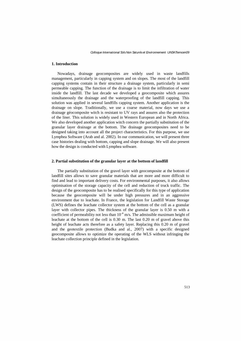
The experiments have been conducted on a hazardous WL during 7 months. A geocomposite with incorporated mini-pipes has been laid directly on the liner, continuously welded with hot air to avoid displacements during backfilling and covered with 0.30 m of crushed gravel material 20/40 mm. The typical cross section of the bottom of the cell is shown in Figure 1 and the structure of the geocomposite is presented in Figure 2.
Figure1. The gravel installation on the geocomposite and the typical cross section
Figure2. Geocomposite structure
2.2. Experimental protocol
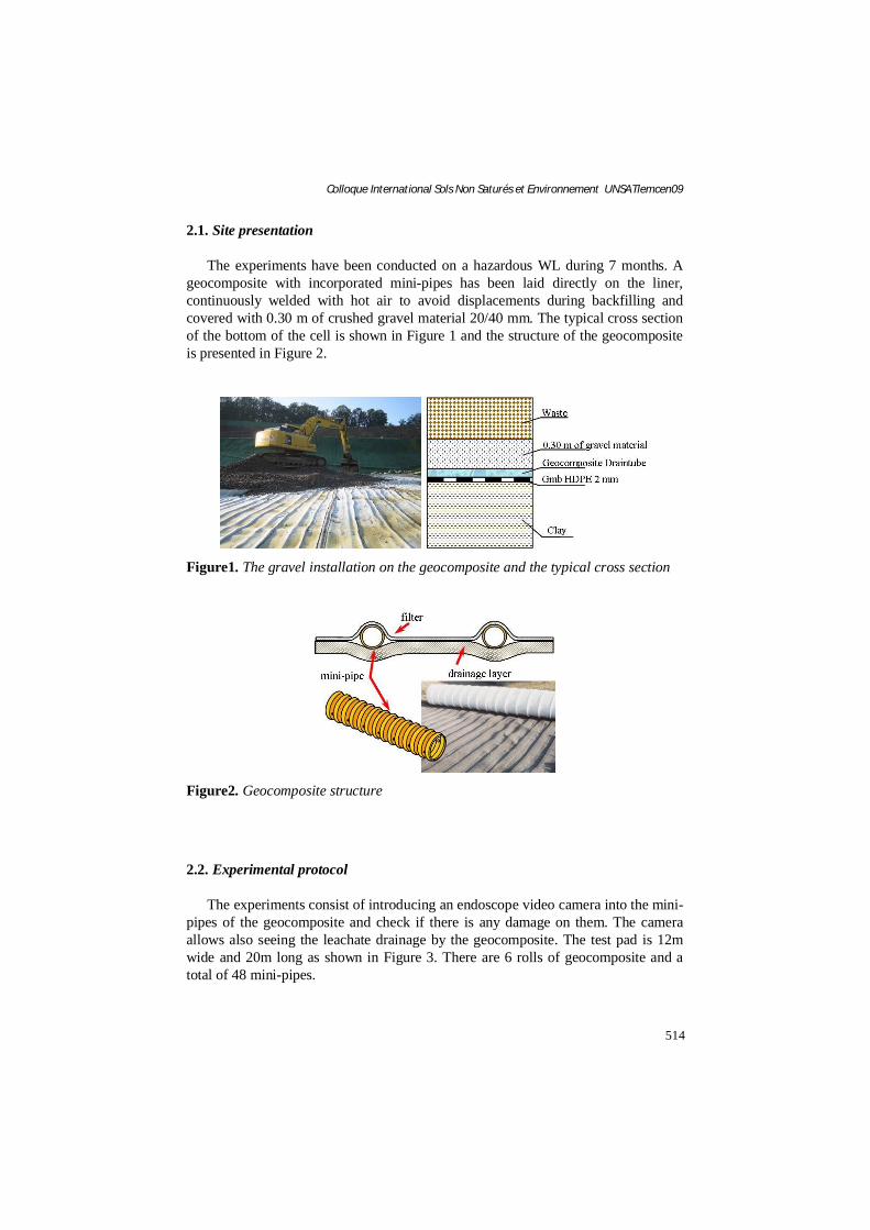
The experiments consist of introducing an endoscope video camera into the mini-pipes of the geocomposite and check if there is any damage on them. The camera allows also seeing the leachate drainage by the geocomposite. The test pad is 12m wide and 20m long as shown in Figure 3. There are 6 rolls of geocomposite and a total of 48 mini-pipes.
515
Colloque International Sols Non Saturés et Environnement UNSATlemcen09
Figure3. Test pad
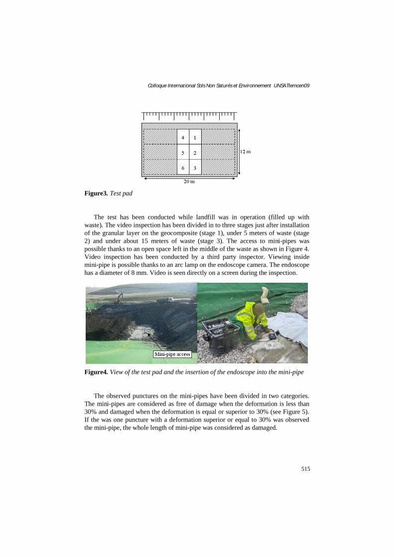
The test has been conducted while landfill was in operation (filled up with waste). The video inspection has been divided in to three stages just after installation of the granular layer on the geocomposite (stage 1), under 5 meters of waste (stage 2) and under about 15 meters of waste (stage 3). The access to mini-pipes was possible thanks to an open space left in the middle of the waste as shown in Figure 4. Video inspection has been conducted by a third party inspector. Viewing inside mini-pipe is possible thanks to an arc lamp on the endoscope camera. The endoscope has a diameter of 8 mm. Video is seen directly on a screen during the inspection.
Figure4. View of the test pad and the insertion of the endoscope into the mini-pipe
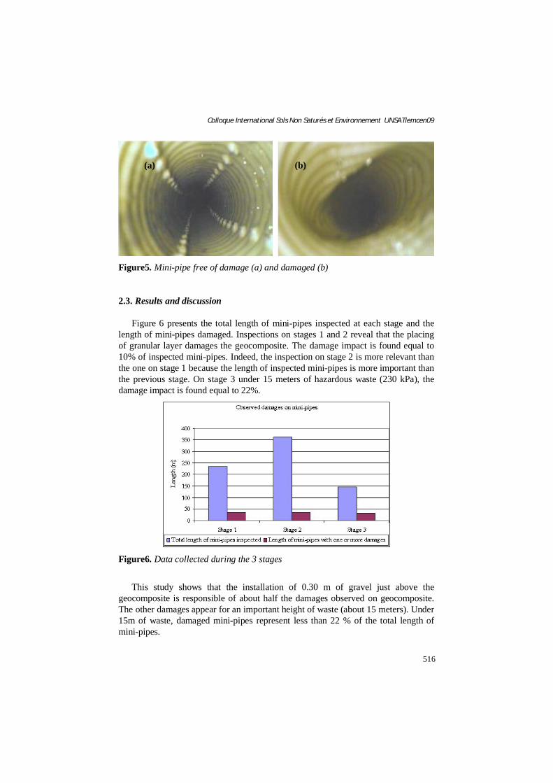
The observed punctures on the mini-pipes have been divided in two categories. The mini-pipes are considered as free of damage when the deformation is less than 30% and damaged when the deformation is equal or superior to 30% (see Figure 5).If the was one puncture with a deformation superior or equal to 30% was observed the mini-pipe, the whole length of mini-pipe was considered as damaged.
516
Colloque International Sols Non Saturés et Environnement UNSATlemcen09
Figure5. Mini-pipe free of damage (a) and damaged (b)
2.3. Results and discussion
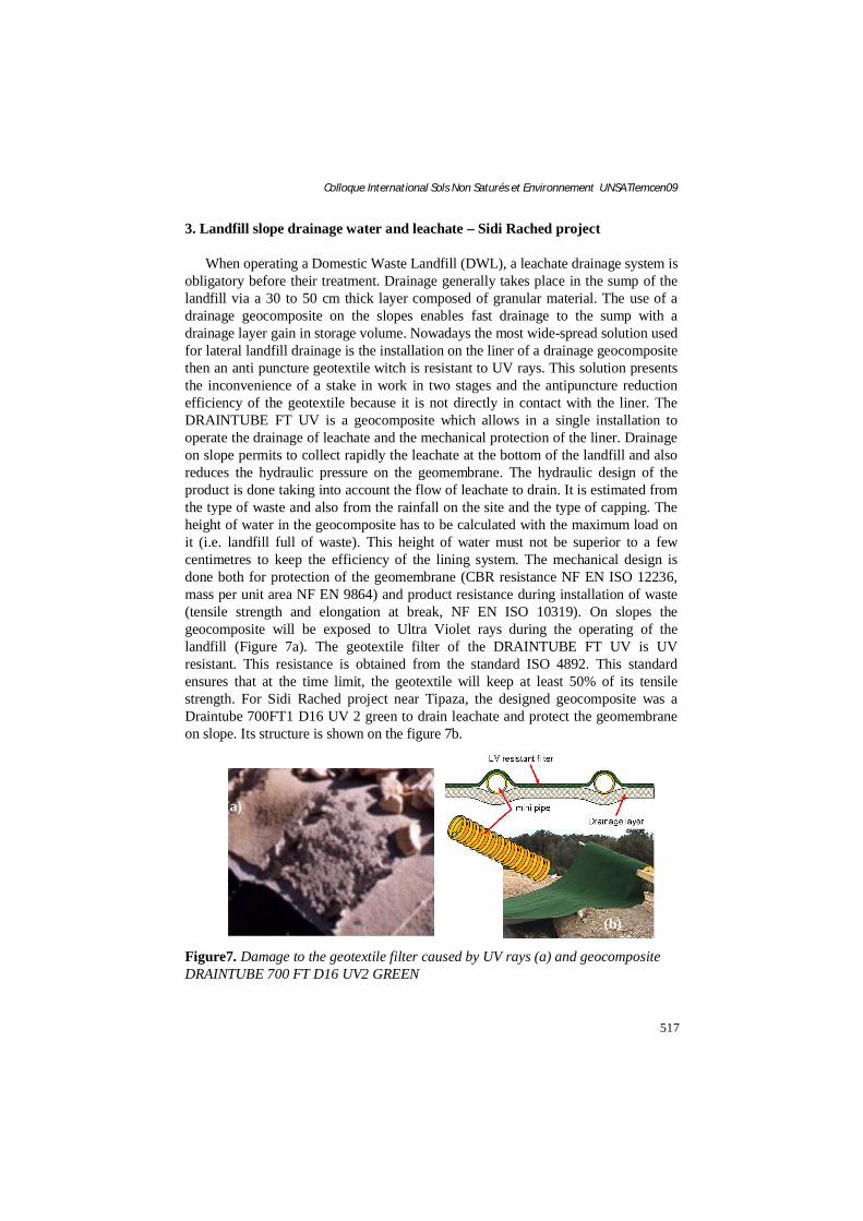
Figure 6 presents the total length of mini-pipes inspected at each stage and the length of mini-pipes damaged. Inspections on stages 1 and 2 reveal that the placing of granular layer damages the geocomposite. The damage impact is found equal to 10% of inspected mini-pipes. Indeed, the inspection on stage 2 is more relevant than the one on stage 1 because the length of inspected mini-pipes is more important than the previous stage. On stage 3 under 15 meters of hazardous waste (230 kPa), the damage impact is found equal to 22%.
Figure6. Data collected during the 3 stages
This study shows that the installation of 0.30 m of gravel just above the geocomposite is responsible of about half the damages observed on geocomposite. The other damages appear for an important height of waste (about 15 meters). Under 15m of waste, damaged mini-pipes represent less than 22 % of the total length of mini-pipes.
(a) (b)
517
Colloque International Sols Non Saturés et Environnement UNSATlemcen09
3. Landfill slope drainage water and leachate – Sidi Rached project
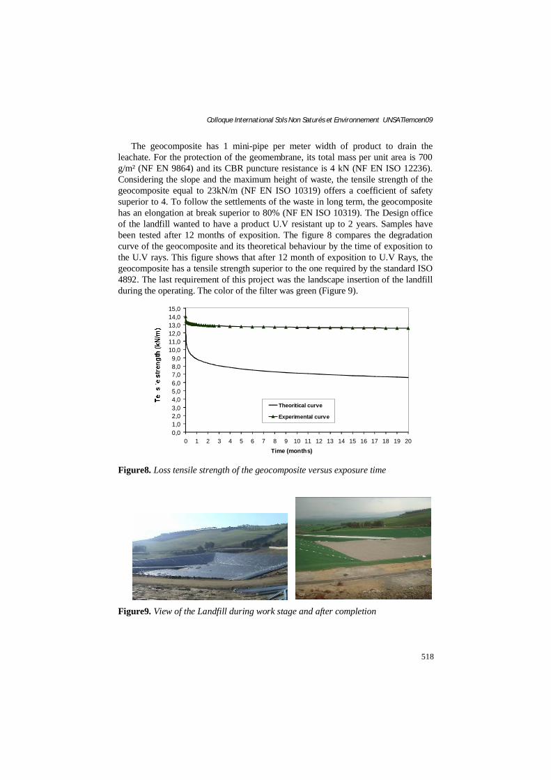
When operating a Domestic Waste Landfill (DWL), a leachate drainage system isobligatory before their treatment. Drainage generally takes place in the sump of the landfill via a 30 to 50 cm thick layer composed of granular material. The use of a drainage geocomposite on the slopes enables fast drainage to the sump with a drainage layer gain in storage volume. Nowadays the most wide-spread solution used for lateral landfill drainage is the installation on the liner of a drainage geocomposite then an anti puncture geotextile witch is resistant to UV rays. This solution presents the inconvenience of a stake in work in two stages and the antipuncture reduction efficiency of the geotextile because it is not directly in contact with the liner. The DRAINTUBE FT UV is a geocomposite which allows in a single installation to operate the drainage of leachate and the mechanical protection of the liner. Drainage on slope permits to collect rapidly the leachate at the bottom of the landfill and also reduces the hydraulic pressure on the geomembrane. The hydraulic design of the product is done taking into account the flow of leachate to drain. It is estimated from the type of waste and also from the rainfall on the site and the type of capping. The height of water in the geocomposite has to be calculated with the maximum load on it (i.e. landfill full of waste). This height of water must not be superior to a few centimetres to keep the efficiency of the lining system. The mechanical design is done both for protection of the geomembrane (CBR resistance NF EN ISO 12236, mass per unit area NF EN 9864) and product resistance during installation of waste (tensile strength and elongation at break, NF EN ISO 10319). On slopes the geocomposite will be exposed to Ultra Violet rays during the operating of the landfill (Figure 7a). The geotextile filter of the DRAINTUBE FT UV is UV resistant. This resistance is obtained from the standard ISO 4892. This standard ensures that at the time limit, the geotextile will keep at least 50% of its tensile strength. For Sidi Rached project near Tipaza, the designed geocomposite was a Draintube 700FT1 D16 UV 2 green to drain leachate and protect the geomembrane on slope. Its structure is shown on the figure 7b.
Figure7. Damage to the geotextile filter caused by UV rays (a) and geocompositeDRAINTUBE 700 FT D16 UV2 GREEN
(a)
(b)
518
Colloque International Sols Non Saturés et Environnement UNSATlemcen09
The geocomposite has 1 mini-pipe per meter width of product to drain the leachate. For the protection of the geomembrane, its total mass per unit area is 700 g/m² (NF EN 9864) and its CBR puncture resistance is 4 kN (NF EN ISO 12236).Considering the slope and the maximum height of waste, the tensile strength of the geocomposite equal to 23kN/m (NF EN ISO 10319) offers a coefficient of safety superior to 4. To follow the settlements of the waste in long term, the geocompositehas an elongation at break superior to 80% (NF EN ISO 10319). The Design officeof the landfill wanted to have a product U.V resistant up to 2 years. Samples have been tested after 12 months of exposition. The figure 8 compares the degradation curve of the geocomposite and its theoretical behaviour by the time of exposition to the U.V rays. This figure shows that after 12 month of exposition to U.V Rays, the geocomposite has a tensile strength superior to the one required by the standard ISO 4892. The last requirement of this project was the landscape insertion of the landfill during the operating. The color of the filter was green (Figure 9).
0,01,02,03,04,05,06,07,08,09,0
10,011,012,013,014,015,0
0 1 2 3 4 5 6 7 8 9 10 11 12 13 14 15 16 17 18 19 20Time (months)
Theoritical curve
Experimental curve
Figure8. Loss tensile strength of the geocomposite versus exposure time
Figure9. View of the Landfill during work stage and after completion
519
Colloque International Sols Non Saturés et Environnement UNSATlemcen09
4. Drainage and waterproofing landfill capping – Satolas Landfill (France)
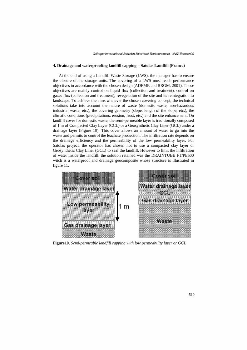
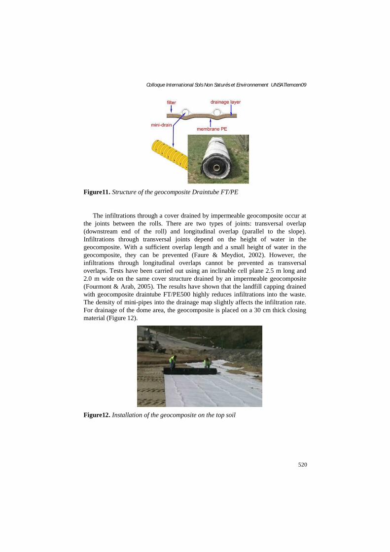
At the end of using a Landfill Waste Storage (LWS), the manager has to ensure the closure of the storage units. The covering of a LWS must reach performance objectives in accordance with the chosen design (ADEME and BRGM, 2001). Those objectives are mainly control on liquid flux (collection and treatment), control on gazes flux (collection and treatment), revegetation of the site and its reintegration to landscape. To achieve the aims whatever the chosen covering concept, the technical solutions take into account the nature of waste (domestic waste, non-hazardous industrial waste, etc.), the covering geometry (slope, length of the slope, etc.), the climatic conditions (precipitations, erosion, frost, etc.) and the site enhancement. On landfill cover for domestic waste, the semi-permeable layer is traditionally composed of 1 m of Compacted Clay Layer (CCL) or a Geosynthetic Clay Liner (GCL) under a drainage layer (Figure 10). This cover allows an amount of water to go into the waste and permits to control the leachate production. The infiltration rate depends on the drainage efficiency and the permeability of the low permeability layer. For Satolas project, the operator has chosen not to use a compacted clay layer or Geosynthetic Clay Liner (GCL) to seal the landfill. However to limit the infiltration of water inside the landfill, the solution retained was the DRAINTUBE FT/PE500 witch is a waterproof and drainage geocomposite whose structure is illustrated in figure 11.
Figure10. Semi-permeable landfill capping with low permeability layer or GCL
520
Colloque International Sols Non Saturés et Environnement UNSATlemcen09
Figure11. Structure of the geocomposite Draintube FT/PE
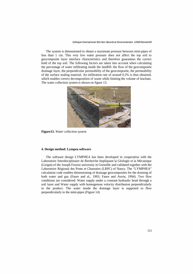
The infiltrations through a cover drained by impermeable geocomposite occur at the joints between the rolls. There are two types of joints: transversal overlap (downstream end of the roll) and longitudinal overlap (parallel to the slope). Infiltrations through transversal joints depend on the height of water in the geocomposite. With a sufficient overlap length and a small height of water in the geocomposite, they can be prevented (Faure & Meydiot, 2002). However, the infiltrations through longitudinal overlaps cannot be prevented as transversal overlaps. Tests have been carried out using an inclinable cell plane 2.5 m long and 2.0 m wide on the same cover structure drained by an impermeable geocomposite (Fourmont & Arab, 2005). The results have shown that the landfill capping drained with geocomposite draintube FT/PE500 highly reduces infiltrations into the waste. The density of mini-pipes into the drainage map slightly affects the infiltration rate. For drainage of the dome area, the geocomposite is placed on a 30 cm thick closing material (Figure 12).
Figure12. Installation of the geocomposite on the top soil
521
Colloque International Sols Non Saturés et Environnement UNSATlemcen09
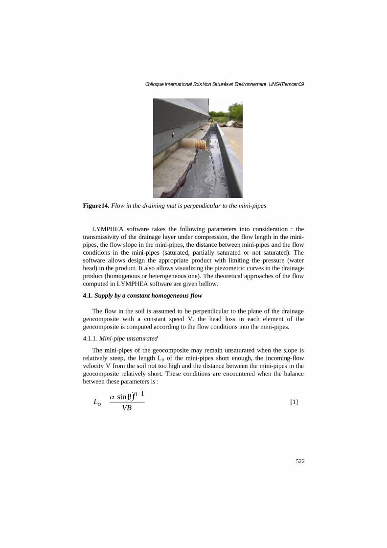
The system is dimensioned to obtain a maximum pressure between mini-pipes of less than 1 cm. This very low water pressure does not affect the top soil to geocomposite layer interface characteristics and therefore guarantees the correct hold of the top soil. The following factors are taken into account when calculating the percentage of water infiltrating inside the landfill: the flow of the geocomposite drainage layer, the perpendicular permeability of the geocomposite, the permeability of the surface sealing material. An infiltration rate of around 0.2% is thus obtained, which enables correct decomposition of waste while limiting the volume of leachate. The water collection system is shown on figure 13.
Figure13. Water collection system
4. Design method: Lympea software
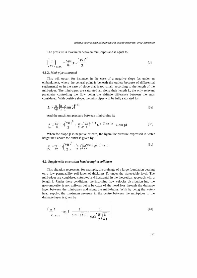
The software design LYMPHEA has been developed in cooperation with the Laboratoire Interdisciplinaire de Recherche Impliquant la Géologie et la Mécanique (Lirigm) of the Joseph Fourier university in Grenoble and validated together with the Laboratoire Régional des Ponts et Chaussées (LRPC) of Nancy. The “LYMPHEA” calculation code enables dimensioning of drainage geocomposites for the draining of both water and gaz (Faure and al., 1993; Faure and Auvin, 1994). Two flow conditions are considered: Water supply under a constant hydraulic head through a soil layer and Water supply with homogenous velocity distribution perpendicularly to the product. The water inside the drainage layer is supposed to flow perpendicularly to the mini-pipes (Figure 14)
522
Colloque International Sols Non Saturés et Environnement UNSATlemcen09
Figure14. Flow in the draining mat is perpendicular to the mini-pipes
LYMPHEA software takes the following parameters into consideration : the transmissivity of the drainage layer under compression, the flow length in the mini-pipes, the flow slope in the mini-pipes, the distance between mini-pipes and the flow conditions in the mini-pipes (saturated, partially saturated or not saturated). The software allows design the appropriate product with limiting the pressure (water head) in the product. It also allows visualizing the piezometric curves in the drainage product (homogenous or heterogeneous one). The theoretical approaches of the flow computed in LYMPHEA software are given bellow.
4.1. Supply by a constant homogeneous flow
The flow in the soil is assumed to be perpendicular to the plane of the drainage geocomposite with a constant speed V. the head loss in each element of the geocomposite is computed according to the flow conditions into the mini-pipes.
4.1.1. Mini-pipe unsaturated
The mini-pipes of the geocomposite may remain unsaturated when the slope is relatively steep, the length L0 of the mini-pipes short enough, the incoming-flow velocity V from the soil not too high and the distance between the mini-pipes in the geocomposite relatively short. These conditions are encountered when the balance between these parameters is :
VBL
no
1sin[1]
523
Colloque International Sols Non Saturés et Environnement UNSATlemcen09
The pressure is maximum between mini-pipes and is equal to:
bVBu VBa
w 28²
max[2]
4.1.2. Mini-pipe saturated
This will occur, for instance, in the case of a negative slope (as under an embankment, where the central point is beneath the outlets because of differential settlements) or in the case of slope that is too small, according to the length of the mini-pipes. The mini-pipes are saturated all along their length L, the only relevant parameter controlling the flow being the altitude difference between the ends considered. With positive slope, the mini-pipes will be fully saturated for:
112 sin
nnn
VBL [3a]
And the maximum pressure between mini-drains is:
sin.2
)1/()2(1/121
8² LLVBa nnnVB
nn
bVBu
w[3b]
When the slope is negative or zero, the hydraulic pressure expressed in water height unit above the outlet is given by:
)1/()2(1/121
8²
2nnnVB
nn
bVBu LVBa
w
[3c]
4.2. Supply with a constant head trough a soil layer
This situation represents, for example, the drainage of a large foundation bearing on a low permeability soil layer of thickness D, under the water-table level. The mini-pipes are considered saturated and horizontal in the theoretical approach with a length L. Under these conditions, the incoming flow velocity distribution into the geocomposite is not uniform but a function of the head loss through the drainage layer between the mini-pipes and along the mini-drains. With h0 being the water-head supply, the maximum pressure in the centre between the mini-pipes in the drainage layer is given by
DkBL
hu
w
2cosh
1cosh
110max
[4a]
524
Colloque International Sols Non Saturés et Environnement UNSATlemcen09
WithDkB
Dk
qd 2tanh2
The discharge capacity of the mini-drains is assumed to be constant and is computed from the flow at the outlet, where the flow rate is a maximum, and hence the discharge capacity is a minimum. The flow rate in each mini-pipes is:
LhqLsQ d tanh)( 02 [4b]
Notations
V: incoming – flow velocity from the soil (m/s)B: half distance between mini-drains (m)L: flow length (m)a: experimental constant b: experimental constant
: transmissivity of the drainage layer (m²/s): experimental constant
n: experimental constant: slope (°)
h: hydraulic head or maximum pressure (m)qd: discharge capacity (m3/s)k: soil permeability (m/s)D: soil thickness (m)
5. Conclusion
A drainage geocomposite with mini-pipes placed at the bottom of LWS in substitution of the geotextile of protection and 0.20 m of granular material has been monitored from the start of the operation up to a height of waste of 15 meters on the top of it. This shows that the installation of 0.30 m of gravel just above the geocomposite induce about half the damages observed on geocomposite why it important to install the gravel carefully on the lining system according to French Geosynthetics committee guideline.
The choice of geosynthetic materials specifically sized allows optimize the realization of the final capping of LWS. Indeed, the realization of the filtration, drainage and waterproofing functions with a unique geocomposite reduce the number of layers to operate particularly on sites difficult of access and increase the stability of the lining system.
Drainage geocomposites were used successfully in Landfill Waste Storage management. Comparatively to the traditional solutions they offers great guarantee on regularity performance, rapidity on execution, saving earthwork and optimise the storage capacity of the cell.
525
Colloque International Sols Non Saturés et Environnement UNSATlemcen09
6. Bibliography
Le dimensionnement et la mise en oeuvre des couvertures de sites de stockage de déchets ménagers et assimilés, Guide ADEMA & BRGM, Mars 2001
Arab R., Gendrin P., Durkheim Y. Landfill Drainage Systems, 7th IGS, Nice 2002, p.745-748.
Budka, A., Bloquet, C., Benneton, J-P., Croissant, D., Girard H., Khay M. Efficiency of different geotextiles for the protection of the geomembrane at landfills. Proceedings of Waste Management, Sardinia 2007, Italy.
Faure Y. H., Meydiot V. (2002) – Secondary function of a complete drainage system: waterproofing,Geosynthetics 7th IGS, Nice 2002, p. 549-553
Faure Y.H., Auvin G. Performance and Design of Geocomposites for Drainage of Gaz. FifthInternational Conference on Geotextiles, Geomembranes and Related Products, 1994. p. 833-836
Faure Y.H. and al. Experimental and Theoretical Methodology to Validate New Geocomposite Structure for Drainage. Geotextiles and Geomembranes vol. 12; 1993 p. 397- 412
Fourmont S., Arab R. Cover landfill drainage systems - Drainage and waterproofing for semi-permeable landfill capping. International Workshop « Hydro-Physico-Mechanics of Landfills » Grenoble 1 University 21-22 March 2005