Embed Size (px)
Citation preview
1
Réducteurs standards à engrenages
Standard gear reducers
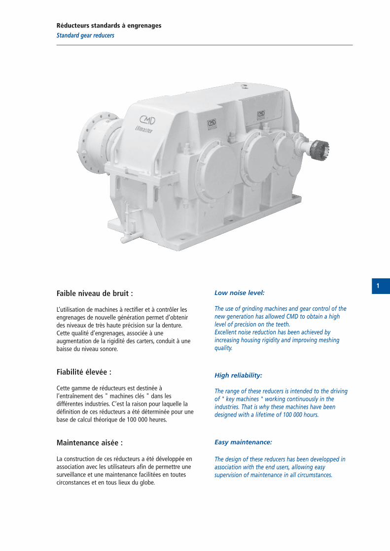
Faible niveau de bruit :
L’utilisation de machines à rectifier et à contrôler lesengrenages de nouvelle génération permet d’obtenirdes niveaux de très haute précision sur la denture.Cette qualité d’engrenages, associée à uneaugmentation de la rigidité des carters, conduit à unebaisse du niveau sonore.
Fiabilité élevée :
Cette gamme de réducteurs est destinée àl’entraînement des " machines clés " dans lesdifférentes industries. C’est la raison pour laquelle ladéfinition de ces réducteurs a été déterminée pour unebase de calcul théorique de 100 000 heures.
Maintenance aisée :
La construction de ces réducteurs a été développée enassociation avec les utilisateurs afin de permettre unesurveillance et une maintenance facilitées en toutescirconstances et en tous lieux du globe.
Low noise level:
The use of grinding machines and gear control of thenew generation has allowed CMD to obtain a highlevel of precision on the teeth.Excellent noise reduction has been achieved byincreasing housing rigidity and improving meshingquality.
High reliability:
The range of these reducers is intended to the drivingof " key machines " working continuously in theindustries. That is why these machines have beendesigned with a lifetime of 100 000 hours.
Easy maintenance:
The design of these reducers has been developped inassociation with the end users, allowing easysupervision of maintenance in all circumstances.

2
3
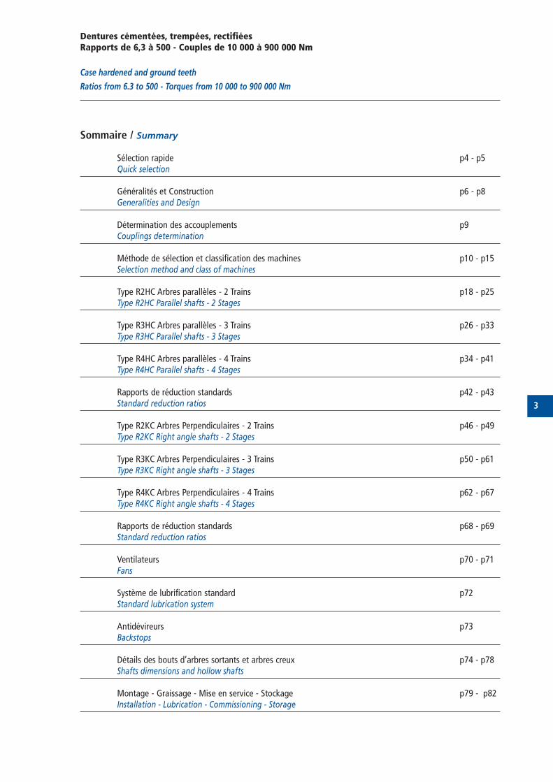
Dentures cémentées, trempées, rectifiéesRapports de 6,3 à 500 - Couples de 10 000 à 900 000 Nm
Case hardened and ground teeth
Ratios from 6.3 to 500 - Torques from 10 000 to 900 000 Nm
Sommaire / Summary
Sélection rapide p4 - p5Quick selection
Généralités et Construction p6 - p8Generalities and Design
Détermination des accouplements p9Couplings determination
Méthode de sélection et classification des machines p10 - p15Selection method and class of machines
Type R2HC Arbres parallèles - 2 Trains p18 - p25Type R2HC Parallel shafts - 2 Stages
Type R3HC Arbres parallèles - 3 Trains p26 - p33Type R3HC Parallel shafts - 3 Stages
Type R4HC Arbres parallèles - 4 Trains p34 - p41Type R4HC Parallel shafts - 4 Stages
Rapports de réduction standards p42 - p43Standard reduction ratios
Type R2KC Arbres Perpendiculaires - 2 Trains p46 - p49Type R2KC Right angle shafts - 2 Stages
Type R3KC Arbres Perpendiculaires - 3 Trains p50 - p61Type R3KC Right angle shafts - 3 Stages
Type R4KC Arbres Perpendiculaires - 4 Trains p62 - p67Type R4KC Right angle shafts - 4 Stages
Rapports de réduction standards p68 - p69Standard reduction ratios
Ventilateurs p70 - p71Fans
Système de lubrification standard p72 Standard lubrication system
Antidévireurs p73Backstops
Détails des bouts d’arbres sortants et arbres creux p74 - p78Shafts dimensions and hollow shafts
Montage - Graissage - Mise en service - Stockage p79 - p82Installation - Lubrication - Commissioning - Storage
4
Sélection rapide
Quick selection
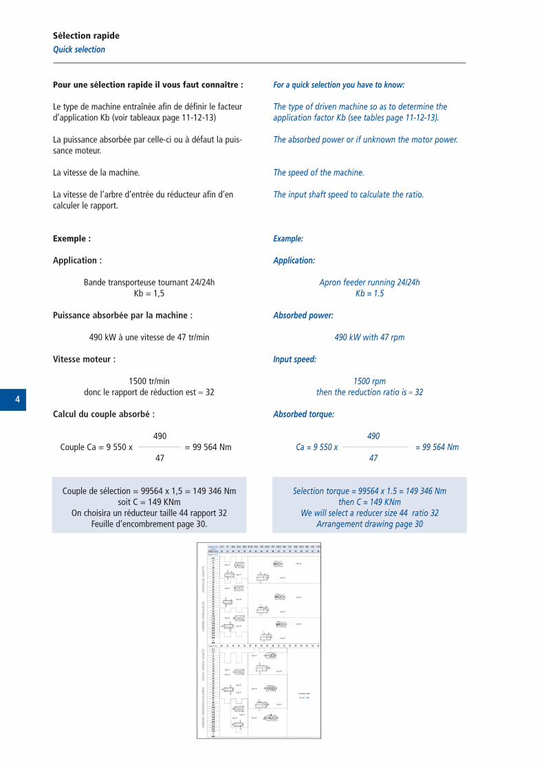
Pour une sélection rapide il vous faut connaître :
Le type de machine entraînée afin de définir le facteurd’application Kb (voir tableaux page 11-12-13)
La puissance absorbée par celle-ci ou à défaut la puis-sance moteur.
La vitesse de la machine.
La vitesse de l’arbre d’entrée du réducteur afin d’encalculer le rapport.
Exemple :
Application :
Bande transporteuse tournant 24/24hKb = 1,5
Puissance absorbée par la machine :
490 kW à une vitesse de 47 tr/min
Vitesse moteur :
1500 tr/mindonc le rapport de réduction est ≈ 32
Calcul du couple absorbé :
490Couple Ca = 9 550 x = 99 564 Nm
47
Couple de sélection = 99564 x 1,5 = 149 346 Nmsoit C = 149 KNm
On choisira un réducteur taille 44 rapport 32Feuille d’encombrement page 30.
For a quick selection you have to know:
The type of driven machine so as to determine theapplication factor Kb (see tables page 11-12-13).
The absorbed power or if unknown the motor power.
The speed of the machine.
The input shaft speed to calculate the ratio.
Example:
Application:
Apron feeder running 24/24hKb = 1.5
Absorbed power:
490 kW with 47 rpm
Input speed:
1500 rpmthen the reduction ratio is ≈ 32
Absorbed torque:
490Ca = 9 550 x = 99 564 Nm
47
Selection torque = 99564 x 1.5 = 149 346 Nmthen C = 149 KNm
We will select a reducer size 44 ratio 32Arrangement drawing page 30
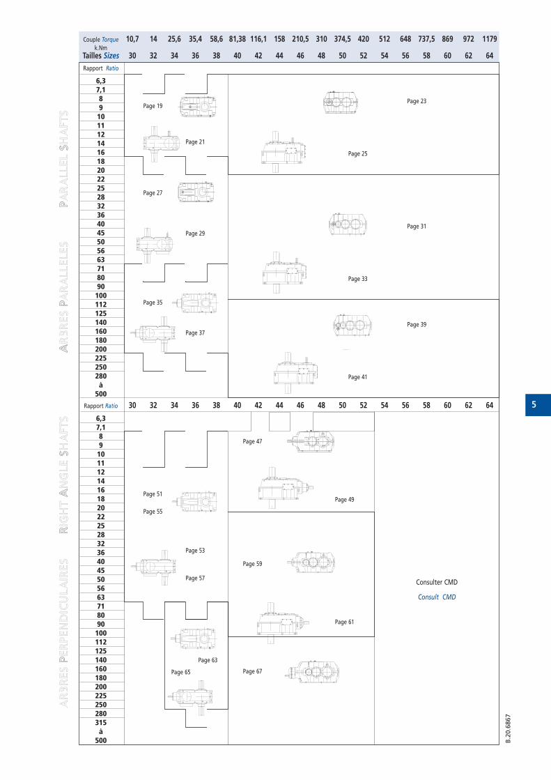
Couple Torque 10,7 14 25,6 35,4 58,6 81,38 116,1 158 210,5 310 374,5 420 512 648 737,5 869 972 1179k.Nm
Tailles Sizes 30 32 34 36 38 40 42 44 46 48 50 52 54 56 58 60 62 64
Rapport Ratio
6,37,1891011121416182022252832364045505663718090100112125140160180200225250280à500
Rapport Ratio 30 32 34 36 38 40 42 44 46 48 50 52 54 56 58 60 62 64
6,37,1891011121416182022252832364045505663718090100112125140160180200225250280315à500
Page 19
Page 21
Page 27
Page 29
Page 35
Page 37
Page 51
Page 53
Page 55
Page 57
Page 63
Page 65
Page 23
Page 25
Page 31
Page 33
Page 39
Page 41
Page 47
Page 49
Page 59
Page 67
Page 61
Consulter CMD
Consult CMD
AARR
BBRR
EESS PP
EERR
PPEE
NNDD
IICCUU
LLAA
IIRREE
SS
RRIIGG
HHTT
AANN
GGLLEE
SSHH
AAFFTT
SS
AARR
BBRR
EESS PP
AARR
AALLLLEE
LLEE
SS
PPAA
RRAA
LLLLEE
LL SS
HHAA
FFTT
SS
5
Couple Torque 10,7 14 25,6 35,4 58,6 81,38 116,1 158 210,5 310 374,5 420 512 648 737,5 869 972 1179k.Nm
Tailles Sizes 30 32 34 36 38 40 42 44 46 48 50 52 54 56 58 60 62 64
Rapport Ratio
6,37,1891011121416182022252832364045505663718090100112125140160180200225250280à500
Rapport Ratio 30 32 34 36 38 40 42 44 46 48 50 52 54 56 58 60 62 64
6,37,1891011121416182022252832364045505663718090100112125140160180200225250280315à500 B
.20.6
867
Page 19
Page 21
Page 27
Page 29
Page 35
Page 37
Page 51
Page 53
Page 55
Page 57
Page 63
Page 65
Page 23
Page 25
Page 31
Page 33
Page 39
Page 41
Page 47
Page 49
Page 59
Page 67
Page 61
Consulter CMD
Consult CMD
AR
BR
ES P
ER
PE
ND
ICU
LA
IRE
S
RIG
HT
AN
GLE
SH
AFT
S
AR
BR
ES P
AR
ALLE
LE
S
PA
RA
LLE
L S
HA
FT
S
6
Généralités et Construction
Generalities and Design
CMD has developped the new range of ERmasterreducers for heavy machines, used in difficultconditions.
This new generation has been designed to satisfycustomers requirements and to increase the followingperformances:
-reduction of the noise level-increase of reliability-reduction of the maintenance cost
The reducers are delivered as standard with two inputshafts from size 48. They are available in 2, 3 or 4 stages for a range of ratios going from 6.3 to 500.
The standardization of many key components duringthe reducers manufacture allows to benefit from theadvantages of lauchings in production, to have stocksand so to optimise manufacturing costs and deliveriesperiods.
For ratios which are not included in the leaflet, pleasecontact CMD. Data shown in this catalogue can be changed withoutnotice.
CMD a développé la nouvelle gamme de réducteursERmaster pour équiper les machines lourdesexploitées dans les conditions difficiles de l'industriedu monde entier.
Cette nouvelle génération a été conçue afin desatisfaire les exigences des utilisateurs et accroître lesperformances dans les domaines suivants :
- baisse du niveau sonore- augmentation de la fiabilité- réduction du coût de la maintenance
Ces réducteurs sont livrés en version standard avecdeux arbres d'entrée à partir de la taille 48. Ils sontdisponibles en 2, 3 ou 4 trains pour une plage derapport s'étalant de 6,3 à 500.
La standardisation de certains composants clés dans lafabrication des réducteurs permet maintenant deprofiter des avantages des lancements en productionrépétitifs, de tenir des stocks et donc d'optimiser lescoûts et les délais de livraison des appareils.
Pour les rapports hors catalogue veuillez nousconsulter.Toutes les données indiquées dans ce cataloguepeuvent être modifiées sans préavis.
7
Généralités et Construction
Generalities and Design
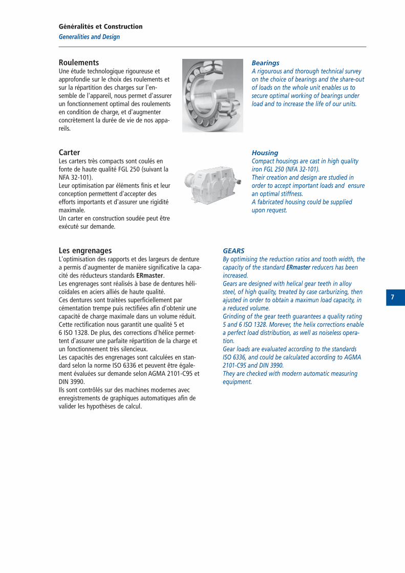
BearingsA rigourous and thorough technical surveyon the choice of bearings and the share-outof loads on the whole unit enables us tosecure optimal working of bearings underload and to increase the life of our units.
HousingCompact housings are cast in high qualityiron FGL 250 (NFA 32-101). Their creation and design are studied inorder to accept important loads and ensurean optimal stiffness.A fabricated housing could be suppliedupon request.
GEARSBy optimising the reduction ratios and tooth width, thecapacity of the standard ERmaster reducers has beenincreased.Gears are designed with helical gear teeth in alloysteel, of high quality, treated by case carburizing, thenajusted in order to obtain a maximun load capacity, in a reduced volume.Grinding of the gear teeth guarantees a quality rating5 and 6 ISO 1328. Morever, the helix corrections enablea perfect load distribution, as well as noiseless opera-tion.Gear loads are evaluated according to the standardsISO 6336, and could be calculated according to AGMA2101-C95 and DIN 3990.They are checked with modern automatic measuringequipment.
RoulementsUne étude technologique rigoureuse etapprofondie sur le choix des roulements etsur la répartition des charges sur l'en-semble de l'appareil, nous permet d'assurerun fonctionnement optimal des roulementsen condition de charge, et d'augmenterconcrètement la durée de vie de nos appa-reils.
CarterLes carters très compacts sont coulés enfonte de haute qualité FGL 250 (suivant laNFA 32-101).Leur optimisation par éléments finis et leurconception permettent d'accepter desefforts importants et d'assurer une rigiditémaximale.Un carter en construction soudée peut êtreexécuté sur demande.
Les engrenagesL'optimisation des rapports et des largeurs de denturea permis d'augmenter de manière significative la capa-cité des réducteurs standards ERmaster.Les engrenages sont réalisés à base de dentures héli-coïdales en aciers alliés de haute qualité.Ces dentures sont traitées superficiellement parcémentation trempe puis rectifiées afin d'obtenir unecapacité de charge maximale dans un volume réduit.Cette rectification nous garantit une qualité 5 et 6 ISO 1328. De plus, des corrections d'hélice permet-tent d'assurer une parfaite répartition de la charge etun fonctionnement très silencieux.Les capacités des engrenages sont calculées en stan-dard selon la norme ISO 6336 et peuvent être égale-ment évaluées sur demande selon AGMA 2101-C95 etDIN 3990.Ils sont contrôlés sur des machines modernes avecenregistrements de graphiques automatiques afin devalider les hypothèses de calcul.
8
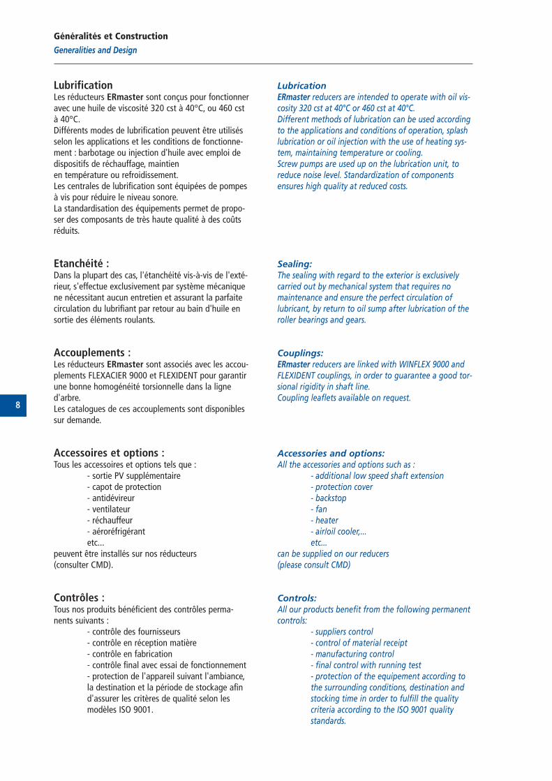
LubricationERmaster reducers are intended to operate with oil vis-cosity 320 cst at 40°C or 460 cst at 40°C.Different methods of lubrication can be used accordingto the applications and conditions of operation, splashlubrication or oil injection with the use of heating sys-tem, maintaining temperature or cooling.Screw pumps are used up on the lubrication unit, toreduce noise level. Standardization of componentsensures high quality at reduced costs.
Sealing:The sealing with regard to the exterior is exclusivelycarried out by mechanical system that requires nomaintenance and ensure the perfect circulation oflubricant, by return to oil sump after lubrication of theroller bearings and gears.
Couplings:ERmaster reducers are linked with WINFLEX 9000 andFLEXIDENT couplings, in order to guarantee a good tor-sional rigidity in shaft line.Coupling leaflets available on request.
Accessories and options:All the accessories and options such as :
- additional low speed shaft extension- protection cover- backstop - fan- heater - air/oil cooler,...etc...
can be supplied on our reducers (please consult CMD)
Controls:All our products benefit from the following permanentcontrols:
- suppliers control- control of material receipt- manufacturing control- final control with running test- protection of the equipement according to the surrounding conditions, destination and stocking time in order to fulfill the quality criteria according to the ISO 9001 quality standards.
Lubrification Les réducteurs ERmaster sont conçus pour fonctionneravec une huile de viscosité 320 cst à 40°C, ou 460 cstà 40°C.Différents modes de lubrification peuvent être utilisésselon les applications et les conditions de fonctionne-ment : barbotage ou injection d'huile avec emploi dedispositifs de réchauffage, maintienen température ou refroidissement.Les centrales de lubrification sont équipées de pompesà vis pour réduire le niveau sonore.La standardisation des équipements permet de propo-ser des composants de très haute qualité à des coûtsréduits.
Etanchéité :Dans la plupart des cas, l'étanchéité vis-à-vis de l'exté-rieur, s'effectue exclusivement par système mécaniquene nécessitant aucun entretien et assurant la parfaitecirculation du lubrifiant par retour au bain d'huile ensortie des éléments roulants.
Accouplements :Les réducteurs ERmaster sont associés avec les accou-plements FLEXACIER 9000 et FLEXIDENT pour garantirune bonne homogénéité torsionnelle dans la ligned'arbre.Les catalogues de ces accouplements sont disponiblessur demande.
Accessoires et options :Tous les accessoires et options tels que :
- sortie PV supplémentaire- capot de protection- antidévireur - ventilateur- réchauffeur- aéroréfrigérantetc...
peuvent être installés sur nos réducteurs (consulter CMD).
Contrôles :Tous nos produits bénéficient des contrôles perma-nents suivants :
- contrôle des fournisseurs- contrôle en réception matière- contrôle en fabrication- contrôle final avec essai de fonctionnement- protection de l'appareil suivant l'ambiance,la destination et la période de stockage afin d'assurer les critères de qualité selon les modèles ISO 9001.
Généralités et Construction
Generalities and Design
9
Détermination des accouplements
Couplings determination
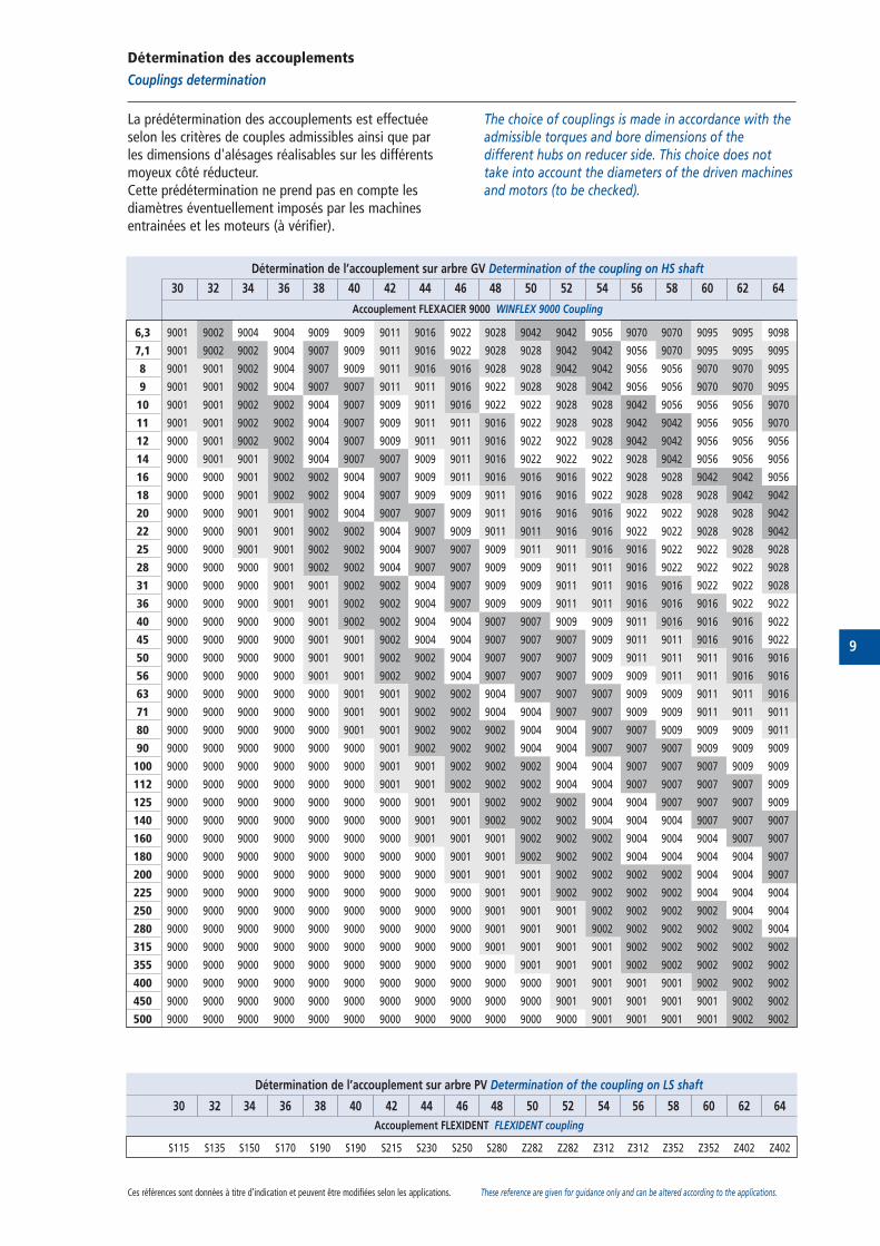
La prédétermination des accouplements est effectuéeselon les critères de couples admissibles ainsi que parles dimensions d'alésages réalisables sur les différentsmoyeux côté réducteur.Cette prédétermination ne prend pas en compte lesdiamètres éventuellement imposés par les machinesentrainées et les moteurs (à vérifier).
The choice of couplings is made in accordance with theadmissible torques and bore dimensions of thedifferent hubs on reducer side. This choice does nottake into account the diameters of the driven machinesand motors (to be checked).
Détermination de l’accouplement sur arbre GV Determination of the coupling on HS shaft
30 32 34 36 38 40 42 44 46 48 50 52 54 56 58 60 62 64
Accouplement FLEXACIER 9000 WINFLEX 9000 Coupling
6,3 9001 9002 9004 9004 9009 9009 9011 9016 9022 9028 9042 9042 9056 9070 9070 9095 9095 9098
7,1 9001 9002 9002 9004 9007 9009 9011 9016 9022 9028 9028 9042 9042 9056 9070 9095 9095 9095
8 9001 9001 9002 9004 9007 9009 9011 9016 9016 9028 9028 9042 9042 9056 9056 9070 9070 9095
9 9001 9001 9002 9004 9007 9007 9011 9011 9016 9022 9028 9028 9042 9056 9056 9070 9070 9095
10 9001 9001 9002 9002 9004 9007 9009 9011 9016 9022 9022 9028 9028 9042 9056 9056 9056 9070
11 9001 9001 9002 9002 9004 9007 9009 9011 9011 9016 9022 9028 9028 9042 9042 9056 9056 9070
12 9000 9001 9002 9002 9004 9007 9009 9011 9011 9016 9022 9022 9028 9042 9042 9056 9056 9056
14 9000 9001 9001 9002 9004 9007 9007 9009 9011 9016 9022 9022 9022 9028 9042 9056 9056 9056
16 9000 9000 9001 9002 9002 9004 9007 9009 9011 9016 9016 9016 9022 9028 9028 9042 9042 9056
18 9000 9000 9001 9002 9002 9004 9007 9009 9009 9011 9016 9016 9022 9028 9028 9028 9042 9042
20 9000 9000 9001 9001 9002 9004 9007 9007 9009 9011 9016 9016 9016 9022 9022 9028 9028 9042
22 9000 9000 9001 9001 9002 9002 9004 9007 9009 9011 9011 9016 9016 9022 9022 9028 9028 9042
25 9000 9000 9001 9001 9002 9002 9004 9007 9007 9009 9011 9011 9016 9016 9022 9022 9028 9028
28 9000 9000 9000 9001 9002 9002 9004 9007 9007 9009 9009 9011 9011 9016 9022 9022 9022 9028
31 9000 9000 9000 9001 9001 9002 9002 9004 9007 9009 9009 9011 9011 9016 9016 9022 9022 9028
36 9000 9000 9000 9001 9001 9002 9002 9004 9007 9009 9009 9011 9011 9016 9016 9016 9022 9022
40 9000 9000 9000 9000 9001 9002 9002 9004 9004 9007 9007 9009 9009 9011 9016 9016 9016 9022
45 9000 9000 9000 9000 9001 9001 9002 9004 9004 9007 9007 9007 9009 9011 9011 9016 9016 9022
50 9000 9000 9000 9000 9001 9001 9002 9002 9004 9007 9007 9007 9009 9011 9011 9011 9016 9016
56 9000 9000 9000 9000 9001 9001 9002 9002 9004 9007 9007 9007 9009 9009 9011 9011 9016 9016
63 9000 9000 9000 9000 9000 9001 9001 9002 9002 9004 9007 9007 9007 9009 9009 9011 9011 9016
71 9000 9000 9000 9000 9000 9001 9001 9002 9002 9004 9004 9007 9007 9009 9009 9011 9011 9011
80 9000 9000 9000 9000 9000 9001 9001 9002 9002 9002 9004 9004 9007 9007 9009 9009 9009 9011
90 9000 9000 9000 9000 9000 9000 9001 9002 9002 9002 9004 9004 9007 9007 9007 9009 9009 9009
100 9000 9000 9000 9000 9000 9000 9001 9001 9002 9002 9002 9004 9004 9007 9007 9007 9009 9009
112 9000 9000 9000 9000 9000 9000 9001 9001 9002 9002 9002 9004 9004 9007 9007 9007 9007 9009
125 9000 9000 9000 9000 9000 9000 9000 9001 9001 9002 9002 9002 9004 9004 9007 9007 9007 9009
140 9000 9000 9000 9000 9000 9000 9000 9001 9001 9002 9002 9002 9004 9004 9004 9007 9007 9007
160 9000 9000 9000 9000 9000 9000 9000 9001 9001 9001 9002 9002 9002 9004 9004 9004 9007 9007
180 9000 9000 9000 9000 9000 9000 9000 9000 9001 9001 9002 9002 9002 9004 9004 9004 9004 9007
200 9000 9000 9000 9000 9000 9000 9000 9000 9001 9001 9001 9002 9002 9002 9002 9004 9004 9007
225 9000 9000 9000 9000 9000 9000 9000 9000 9000 9001 9001 9002 9002 9002 9002 9004 9004 9004
250 9000 9000 9000 9000 9000 9000 9000 9000 9000 9001 9001 9001 9002 9002 9002 9002 9004 9004
280 9000 9000 9000 9000 9000 9000 9000 9000 9000 9001 9001 9001 9002 9002 9002 9002 9002 9004
315 9000 9000 9000 9000 9000 9000 9000 9000 9000 9001 9001 9001 9001 9002 9002 9002 9002 9002
355 9000 9000 9000 9000 9000 9000 9000 9000 9000 9000 9001 9001 9001 9002 9002 9002 9002 9002
400 9000 9000 9000 9000 9000 9000 9000 9000 9000 9000 9000 9001 9001 9001 9001 9002 9002 9002
450 9000 9000 9000 9000 9000 9000 9000 9000 9000 9000 9000 9001 9001 9001 9001 9001 9002 9002
500 9000 9000 9000 9000 9000 9000 9000 9000 9000 9000 9000 9000 9001 9001 9001 9001 9002 9002
Détermination de l’accouplement sur arbre PV Determination of the coupling on LS shaft
30 32 34 36 38 40 42 44 46 48 50 52 54 56 58 60 62 64
Accouplement FLEXIDENT FLEXIDENT coupling
S115 S135 S150 S170 S190 S190 S215 S230 S250 S280 Z282 Z282 Z312 Z312 Z352 Z352 Z402 Z402
Ces références sont données à titre d’indication et peuvent être modifiées selon les applications. These reference are given for guidance only and can be altered according to the applications.
10
Méthode de sélection
Selection method
Puissance :
1) Détermination du rapport de réduction u :
Le rapport de réduction est obtenu en divisant la vites-se de l’arbre grande vitesse (GV) par celle de l’arbrepetite vitesse (PV). Les tableaux de sélection donnentles rapports standards.
u= N1/N2
2) Détermination du facteur de service Kb :
Le facteur de service Kb est déterminé suivant l’appli-cation de l’installation. La correspondance entre l’ap-plication et le facteur de service Kb s’effectue à l’aidedes tableaux page 11 à 13.
3) Détermination de la puissance de sélection du
réducteur PS :
La puissance de sélection PS est obtenue en multi-pliant la puissance effective à transmettre à la machi-ne menée Pa par le facteur de service Kb.
PS= Pa x Kb
4) Capacité nominale du réducteur PN :
Les tableaux de sélection donnent les capacités nomi-nales des réducteurs exprimées en kW. Les calculs sonteffectués en suivant la norme ISO 6336.
5) Sélection du type et de la taille :
Sélectionner dans les tableaux de capacités nominalesPN le rapport standard le plus proche du rapport calcu-lé en 1).Sur la ligne correspondant au rapport standard et à lavitesse d’entrée recherchée, retenir la taille d’appareildont la puissance admissible PN est égale ou supérieureà la puissance de sélection PS calculée en 3).
PN>PS
Veuillez nous consulter pour des couples de démarrageou de freinage dépassant deux fois le couple moteur,de même que pour les applications où il y a plus dedix démarrages par heure.
Power:
1) Selection of the reduction ratio u:
Number of high speed shaft rotation (HS)u=
Number of slow speed shaft rotation (LS)
u= N1/N2
2) Selection of the service factor Kb:
The service factor Kb is determined according to theapplication. The Kb value is given in the tables page 11to 13 according to the choice of application.
3) Selection of reducer’s power PS:
Required power PS is obtained by multiplying the effec-tive power to be transmitted to the driven machine Paby the service factor Kb.
PS= Pa x Kb
4) Nominal capacity of the reducer PN:
The selection tables give the nominal capacities of thereducers in kW. Calculations have been made accordingto ISO 6336 standard.
5) Type and size selection
Select from nominal capacities PN the nearest standardratio to the one calculated in 1).Use the nearest standard ratio to obtain and use inputspeed to select the size of the unit for which the admis-sible power PN is equal or higher than the requiredpower PS calculated in 3).
PN>PS
Please contact CMD in case of starting or breakingtorque being at least two times higher than the motortorque or for application in which the number of startsper hour is more than 10.
11
B.3
0.6
800
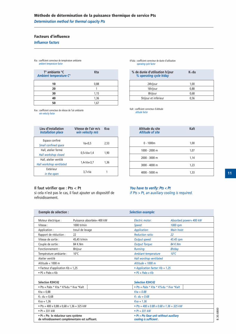
Exemple de sélection : Selection example:
Moteur électrique : Puissance absorbée= 400 kW Electric motor: Absorbed power= 400 kW
Vitesse : 1000 tr/min Speed: 1000 rpm
Application : treuil de levage Application: Main hoist
Rapport de réduction : 22 Reduction ratio: 22
Vitesse de sortie : 45,45 tr/min Output speed: 45.45 rpm
Couple de sortie : 84 K.Nm Output Torque: 84 K.Nm
Fonctionnement : 8h/jour Running: 8h/day
Température ambiante : 10°C Ambiant temperature 10°C
Atelier ventilé Hall worshop ventilated
Altitude < 1000 m Altitude < 1000 m
• Facteur d’application Kb = 1,25 • Application factor: Kb = 1.25
• PS = Pabs x Kb • PS = Pabs x Kb
Sélection R3HC42 Selection R3HC42
• Pts = Pabs * Kta * K%du * Kva *Kalt • Pts = Pabs * Kta * K%du * Kva *Kalt
Kta = 0,88 Kta = 0.88
K% du = 0,68 K% du = 0.68
Kva = 1,36 Kva = 1.36
• Pts = 400 x 0,88 x 0,68 x 1,36 = 325 kW • Pts = 400 x 0.88 x 0.68 x 1.36 = 325 kW
• Pt = 331 kW • Pt = 331 kW
• Pt > Pts le réducteur sans système • Pt > Pts Gear unit without auxiliaryde refroidissement complémentaire est suffisant. cooling is sufficient .
% de durée d’utilisation h/jour K% du% operating cycle h/day
24h/jour 1,00
16h/jour 0,88
8h/jour 0,68
5h/jour et inférieur 0,56
Méthode de détermination de la puissance thermique de service Pts
Determination method for thermal capacity Pts
Facteurs d’influence
Influence factors
Kta : coefficient correcteur de température ambianteambient temperature factor
K%du : coefficient correcteur de durée d’utilisationoperating cycle factor
Kva : coefficient correcteur de vitesse de l’air ambiante win velocity factor
Kalt : coefficient correcteur d’altitudealtitude factor
Lieu d’installation Vitesse de l’air m/s KvaInstallation place win velocity m/s
Espace confiné
Small confined spaceVa<0,5 2,53
Hall, atelier fermé
Hall workshop closed0,5<Va<1,4 1,90
Hall, atelier ventilé
Hall workshop ventilated1,4<Va<3,7 1,36
Extérieur
in the open3,7<Va 1
Altitude du site KaltAltitude of site
0 - 1000m 1,00
1000 - 2000 m 1,07
2000 - 3000 m 1,14
3000 - 4000 m 1,23
4000 - 5000 m 1,33
Il faut vérifier que : Pts < Ptsi cela n’est pas le cas, il faut ajouter un dispositif derefroidissement.
You have to verify: Pts < Ptif Pts > Pt, an auxiliary cooling is required.
T° ambiante °C KtaAmbient temperature C°
10 0,88
20 1
30 1,15
40 1,36
50 1,67
12
B.4
0.6
800
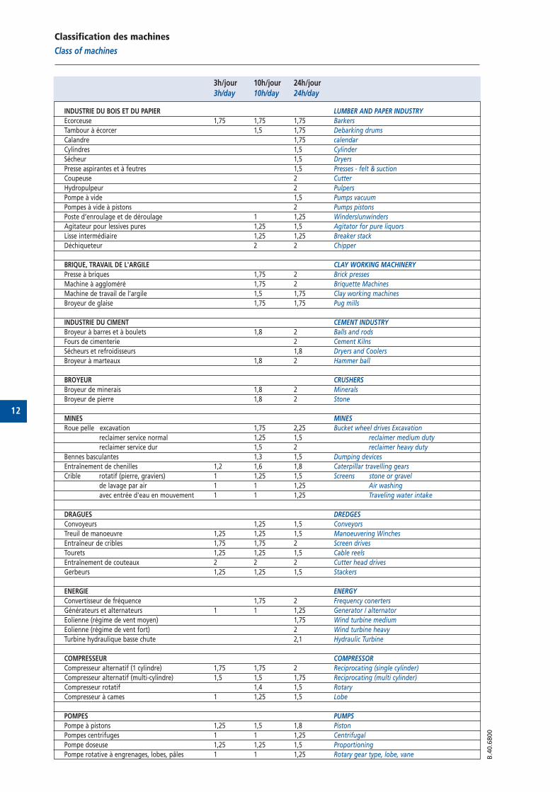
Classification des machines
Class of machines
3h/jour 10h/jour 24h/jour3h/day 10h/day 24h/day
INDUSTRIE DU BOIS ET DU PAPIER LUMBER AND PAPER INDUSTRY
Ecorceuse 1,75 1,75 1,75 Barkers
Tambour à écorcer 1,5 1,75 Debarking drums
Calandre 1,75 calendar
Cylindres 1,5 Cylinder
Sécheur 1,5 Dryers
Presse aspirantes et à feutres 1,5 Presses - felt & suction
Coupeuse 2 Cutter
Hydropulpeur 2 Pulpers
Pompe à vide 1,5 Pumps vacuum
Pompes à vide à pistons 2 Pumps pistons
Poste d’enroulage et de déroulage 1 1,25 Winders/unwinders
Agitateur pour lessives pures 1,25 1,5 Agitator for pure liquors
Lisse intermédiaire 1,25 1,25 Breaker stack
Déchiqueteur 2 2 Chipper
BRIQUE, TRAVAIL DE L'ARGILE CLAY WORKING MACHINERY
Presse à briques 1,75 2 Brick presses
Machine à aggloméré 1,75 2 Briquette Machines
Machine de travail de l’argile 1,5 1,75 Clay working machines
Broyeur de glaise 1,75 1,75 Pug mills
INDUSTRIE DU CIMENT CEMENT INDUSTRY
Broyeur à barres et à boulets 1,8 2 Balls and rods
Fours de cimenterie 2 Cement Kilns
Sécheurs et refroidisseurs 1,8 Dryers and Coolers
Broyeur à marteaux 1,8 2 Hammer ball
BROYEUR CRUSHERS
Broyeur de minerais 1,8 2 Minerals
Broyeur de pierre 1,8 2 Stone
MINES MINES
Roue pelle excavation 1,75 2,25 Bucket wheel drives Excavation
reclaimer service normal 1,25 1,5 reclaimer medium duty
reclaimer service dur 1,5 2 reclaimer heavy duty
Bennes basculantes 1,3 1,5 Dumping devices
Entraînement de chenilles 1,2 1,6 1,8 Caterpillar travelling gears
Crible rotatif (pierre, graviers) 1 1,25 1,5 Screens stone or gravel
de lavage par air 1 1 1,25 Air washing
avec entrée d'eau en mouvement 1 1 1,25 Traveling water intake
DRAGUES DREDGES
Convoyeurs 1,25 1,5 Conveyors
Treuil de manoeuvre 1,25 1,25 1,5 Manoeuvering Winches
Entraîneur de cribles 1,75 1,75 2 Screen drives
Tourets 1,25 1,25 1,5 Cable reels
Entraînement de couteaux 2 2 2 Cutter head drives
Gerbeurs 1,25 1,25 1,5 Stackers
ENERGIE ENERGY
Convertisseur de fréquence 1,75 2 Frequency conerters
Générateurs et alternateurs 1 1 1,25 Generator / alternator
Eolienne (régime de vent moyen) 1,75 Wind turbine medium
Eolienne (régime de vent fort) 2 Wind turbine heavy
Turbine hydraulique basse chute 2,1 Hydraulic Turbine
COMPRESSEUR COMPRESSOR
Compresseur alternatif (1 cylindre) 1,75 1,75 2 Reciprocating (single cylinder)
Compresseur alternatif (multi-cylindre) 1,5 1,5 1,75 Reciprocating (multi cylinder)
Compresseur rotatif 1,4 1,5 Rotary
Compresseur à cames 1 1,25 1,5 Lobe
POMPES PUMPS
Pompe à pistons 1,25 1,5 1,8 Piston
Pompes centrifuges 1 1 1,25 Centrifugal
Pompe doseuse 1,25 1,25 1,5 Proportioning
Pompe rotative à engrenages, lobes, pâles 1 1 1,25 Rotary gear type, lobe, vane
13
B.4
0.6
800
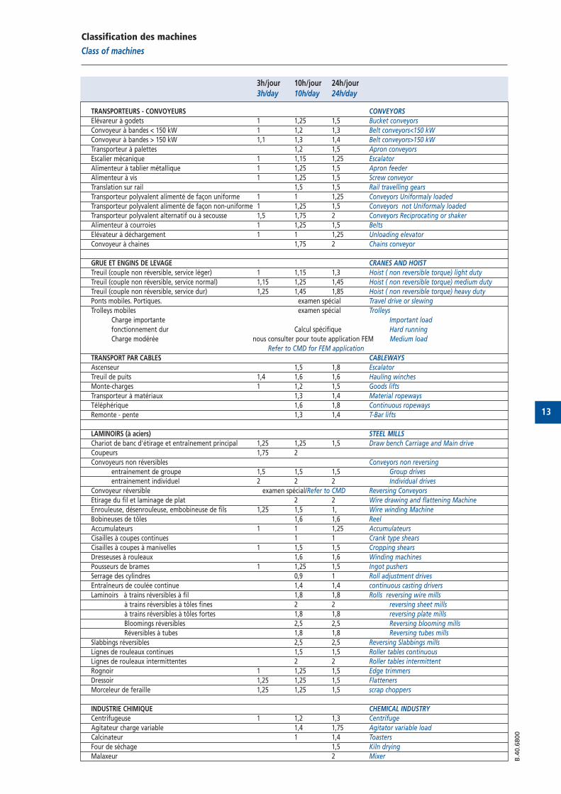
Classification des machines
Class of machines
3h/jour 10h/jour 24h/jour3h/day 10h/day 24h/day
TRANSPORTEURS - CONVOYEURS CONVEYORS
Elévareur à godets 1 1,25 1,5 Bucket conveyors
Convoyeur à bandes < 150 kW 1 1,2 1,3 Belt conveyors<150 kW
Convoyeur à bandes > 150 kW 1,1 1,3 1,4 Belt conveyors>150 kW
Transporteur à palettes 1,2 1,5 Apron conveyors
Escalier mécanique 1 1,15 1,25 Escalator
Alimenteur à tablier métallique 1 1,25 1,5 Apron feeder
Alimenteur à vis 1 1,25 1,5 Screw conveyor
Translation sur rail 1,5 1,5 Rail travelling gears
Transporteur polyvalent alimenté de façon uniforme 1 1 1,25 Conveyors Uniformaly loaded
Transporteur polyvalent alimenté de façon non-uniforme 1 1,25 1,5 Conveyors not Uniformaly loaded
Transporteur polyvalent alternatif ou à secousse 1,5 1,75 2 Conveyors Reciprocating or shaker
Alimenteur à courroies 1 1,25 1,5 Belts
Elévateur à déchargement 1 1 1,25 Unloading elevator
Convoyeur à chaines 1,75 2 Chains conveyor
GRUE ET ENGINS DE LEVAGE CRANES AND HOIST
Treuil (couple non réversible, service léger) 1 1,15 1,3 Hoist ( non reversible torque) light duty
Treuil (couple non réversible, service normal) 1,15 1,25 1,45 Hoist ( non reversible torque) medium duty
Treuil (couple non réversible, service dur) 1,25 1,45 1,85 Hoist ( non reversible torque) heavy duty
Ponts mobiles. Portiques. examen spécial Travel drive or slewing
Trolleys mobiles examen spécial Trolleys
Charge importante Important load
fonctionnement dur Calcul spécifique Hard running
Charge modérée nous consulter pour toute application FEM Medium load
Refer to CMD for FEM application
TRANSPORT PAR CABLES CABLEWAYS
Ascenseur 1,5 1,8 Escalator
Treuil de puits 1,4 1,6 1,6 Hauling winches
Monte-charges 1 1,2 1,5 Goods lifts
Transporteur à matériaux 1,3 1,4 Material ropeways
Téléphérique 1,6 1,8 Continuous ropeways
Remonte - pente 1,3 1,4 T-Bar lifts
LAMINOIRS (à aciers) STEEL MILLS
Chariot de banc d'étirage et entraînement principal 1,25 1,25 1,5 Draw bench Carriage and Main drive
Coupeurs 1,75 2
Convoyeurs non réversibles Conveyors non reversing
entrainement de groupe 1,5 1,5 1,5 Group drives
entrainement individuel 2 2 2 Individual drives
Convoyeur réversible examen spécial/Refer to CMD Reversing Conveyors
Etirage du fil et laminage de plat 2 2 Wire drawing and flattening Machine
Enrouleuse, désenrouleuse, embobineuse de fils 1,25 1,5 1, Wire winding Machine
Bobineuses de tôles 1,6 1,6 Reel
Accumulateurs 1 1 1,25 Accumulateurs
Cisailles à coupes continues 1 1 Crank type shears
Cisailles à coupes à manivelles 1 1,5 1,5 Cropping shears
Dresseuses à rouleaux 1,6 1,6 Winding machines
Pousseurs de brames 1 1,25 1,5 Ingot pushers
Serrage des cylindres 0,9 1 Roll adjustment drives
Entraîneurs de coulée continue 1,4 1,4 continuous casting drivers
Laminoirs à trains réversibles à fil 1,8 1,8 Rolls reversing wire mills
à trains réversibles à tôles fines 2 2 reversing sheet mills
à trains réversibles à tôles fortes 1,8 1,8 reversing plate mills
Bloomings réversibles 2,5 2,5 Reversing blooming mills
Réversibles à tubes 1,8 1,8 Reversing tubes mills
Slabbings réversibles 2,5 2,5 Reversing Slabbings mills
Lignes de rouleaux continues 1,5 1,5 Roller tables continuous
Lignes de rouleaux intermittentes 2 2 Roller tables intermittent
Rognoir 1 1,25 1,5 Edge trimmers
Dressoir 1,25 1,25 1,5 Flatteners
Morceleur de feraille 1,25 1,25 1,5 scrap choppers
INDUSTRIE CHIMIQUE CHEMICAL INDUSTRY
Centrifugeuse 1 1,2 1,3 Centrifuge
Agitateur charge variable 1,4 1,75 Agitator variable load
Calcinateur 1 1,4 Toasters
Four de séchage 1,5 Kiln drying
Malaxeur 2 Mixer
14
B.4
0.6
800
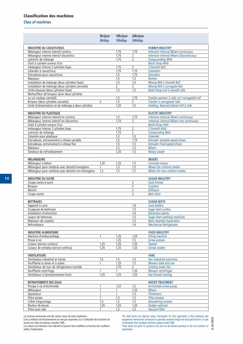
Classification des machines
Class of machines
3h/jour 10h/jour 24h/jour3h/day 10h/day 24h/day
INDUSTRIE DU CAOUTCHOUC RUBBER INDUSTRYMélangeur interne intensif continu 1,75 1,75 Intensive internal Mixers continuousMélangeur interne intensif discontinu 1,75 2 Intensive internal Mixers DiscontinuousLaminoir de mélange 1,75 2 Compounding MillsOutil à cylindre suiveur d'un Batch Drop Millsmélangeur interne 2 cylindres lisses 1,75 2 2 Smooth RollCalandre à caoutchouc 1,75 1,75 CalendersExtrudeuse pour caoutchouc 1,5 1,75 ExtrudersMalaxeur 1,5 1,5 RefinerInstallation de mélange (deux cylindres lisses) 1,5 1,5 Mixing Mill 2 Smooth RollInstallation de mélange (deux cylindres cannelés) 2 2 Mixing Mill 2 corrugate RollUnité doseuse (deux cylindres lisses) 1,5 1,5 Batch drop mill 2 smooth rollsRéchauffeur de broyeur (avec deux cylindres ou un rouleau cannelé) 1,5 1,75 Cracker warmer 2 rolls; or1 corrugated rollBroyeur (deux cylindres cannelés) 2 1,5 2 Cracker 2 corrugated rollsUnité d'alimentation et de mélange à deux cylindres 1,25 1,5 Holding, feed and blend mill 2 rolls
INDUSTRIE DU PLASTIQUE PLASTIC INDUSTRYMélangeur interne intensif en continu 1,5 1,75 intensive internal Mixers continuousMélangeur interne intensif en discontinu 1,75 2 intensive internal Mixers non continuousOutil à cylindre suiveur d'un Batch Drop mills mélangeur interne 2 cylindres lisses 1,75 2 2 Smooth RollsLaminoir de mélange 1,75 2 Compouding MillsCalandre pour plastique 1,5 1,5 CalenderExtrudeuse, entraînement à vitesse variable 1,5 1,75 Extruder Variable speed drivesExtrudeuse, entraînement à vitesse fixe 1,5 1,5 Extruder Fixed speed drivesMalaxeur 1,5 1,5 MixersTambour de refroidissement 1,25 1,5 Rotary cooler
MELANGEURS MIXERSMélangeur à béton 1,25 1,25 1,5 Concrete mixersMélangeur pour matières avec densité homogène 1 1,3 1,5 Mixers for uniform mediaMélangeur pour matières avec densité non-homogène 1,2 1,5 1,7 Mixers for non uniform media
INDUSTRIE DU SUCRE SUGAR INDUSTRYCoupe canne à sucre 2 Cane KnivesBroyeur 2 CrushersMoulin 2 DiffusersCoupe racine 2 Beet slicer
BETTRAVES SUGAR BEETSAppareil à cuire 1,4 Juice boilersCoupeuse de bettraves 1,5 Sugar beet cuttersInstallation d'extraction 1,4 Extraction plantsLaveur de bettraves 1,5 Sugar beet washing machinesMalaxeur de cossette 1,2 Beet cossettes maceratorsRefroidisseur 1,4 Mechanical Refrigerator
INDUSTRIE ALIMENTAIRE FOOD INDUSTRYMachine d'embouteillage 1 1,25 1,25 Filling machinePresse à vis 1,25 1,5 Screw pressesCuiseur (service continu) 1,25 1,25 1,25 ToasterCuiseur de céréales (service continu) 1,25 1,25 1,25 Cereal cooker
VENTILATEURS FANSVentilateur industriel et minier 1,5 1,5 1,5 Fan industrial and mineSoufflante à cames et à aubes 1 1,25 1,5 Blowers lobe and vanVentilateur de tour de réfrigération humide 1,75 2 Cooling tower fanSoufflante centrifuge 1 1 1,25 Blowers centrifugalVentilateur à fonctionnement forcé 1,25 1,25 1,25 Fan forced running
RETRAITEMENTS DES EAUX WATER TREATMENTPompe à vis d'Archimède 1 1,25 1,5 Archimede screw pumpMélangeur 1 1 1,25 MixersEpaissiseur 1 1 1,3 ThickenersFiltre presse 1 1,3 1,5 Filter pressesCrible d'égouttage 1,5 1,5 1,5 Dewatering screensRacleur de boues 1,25 1,25 1,25 Sludge collectorFiltre sous vide 1 1,3 1,5 Vacuum filter
Les facteurs mentionnés sont des valeurs issues de notre expérience.Si les conditions de fonctionnement ne sont pas respectées, ou si l’utilisation des machines detravail non citées est prévue, consulter CMD.Ces valeurs sont données à tire indicatif est peuvent être modifiées en fonction des conditionsréelles d'exploitation
The listed factor are impirical values. Prerequisite for their application is that machinery andequipement mentionned correspond to generally accepted design and load specifications. In caseof deviations from standard conditions, please contact CMD.These values are given for guidance only and can be altered according to the real condition ofexploitation
15
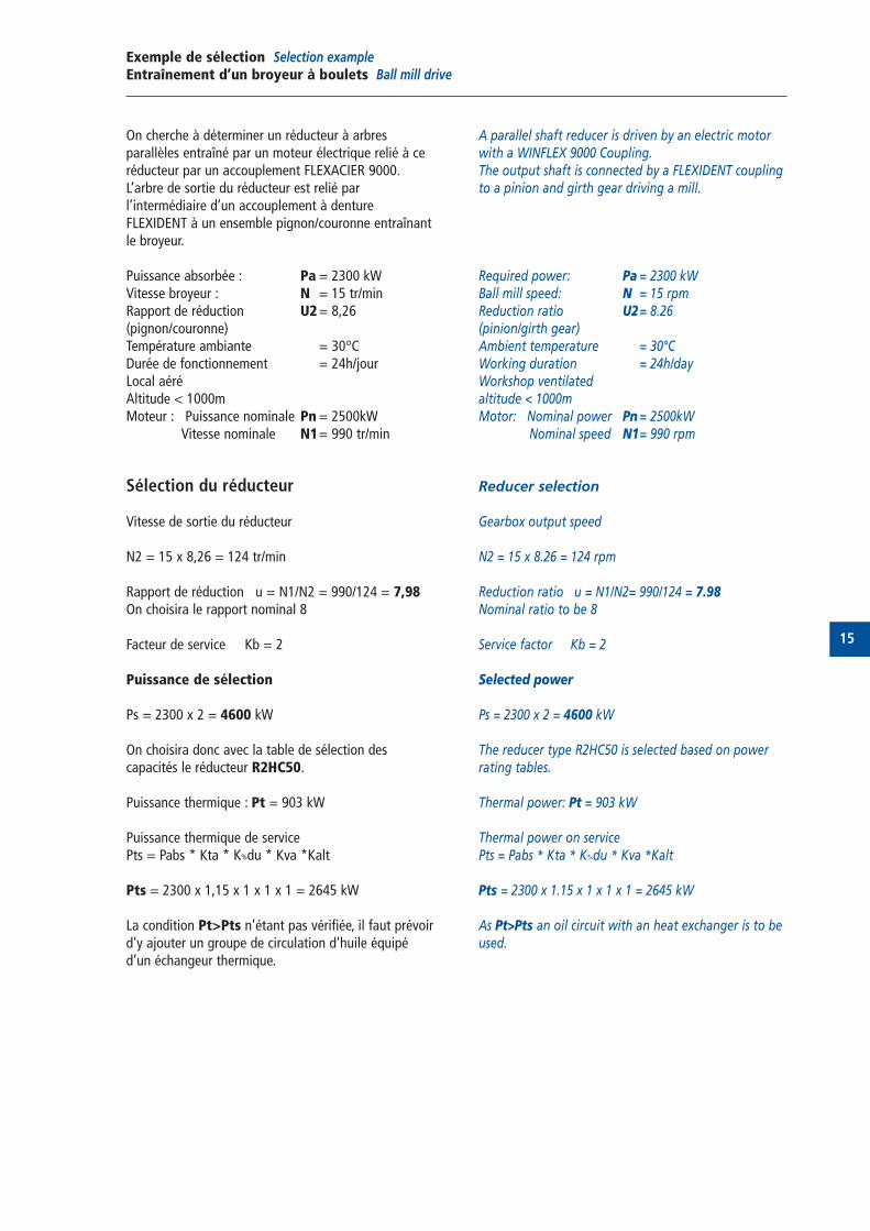
Exemple de sélection Selection example Entraînement d’un broyeur à boulets Ball mill drive
On cherche à déterminer un réducteur à arbres parallèles entraîné par un moteur électrique relié à ceréducteur par un accouplement FLEXACIER 9000.L’arbre de sortie du réducteur est relié par l’intermédiaire d’un accouplement à denture FLEXIDENT à un ensemble pignon/couronne entraînantle broyeur.
Puissance absorbée : Pa = 2300 kWVitesse broyeur : N = 15 tr/minRapport de réduction U2= 8,26(pignon/couronne)Température ambiante = 30°CDurée de fonctionnement = 24h/jourLocal aéréAltitude < 1000mMoteur : Puissance nominale Pn= 2500kW
Vitesse nominale N1= 990 tr/min
Sélection du réducteur
Vitesse de sortie du réducteur
N2 = 15 x 8,26 = 124 tr/min
Rapport de réduction u = N1/N2 = 990/124 = 7,98On choisira le rapport nominal 8
Facteur de service Kb = 2
Puissance de sélection
Ps = 2300 x 2 = 4600 kW
On choisira donc avec la table de sélection des capacités le réducteur R2HC50.
Puissance thermique : Pt = 903 kW
Puissance thermique de servicePts = Pabs * Kta * K%du * Kva *Kalt
Pts = 2300 x 1,15 x 1 x 1 x 1 = 2645 kW
La condition Pt>Pts n’étant pas vérifiée, il faut prévoird’y ajouter un groupe de circulation d’huile équipéd’un échangeur thermique.
A parallel shaft reducer is driven by an electric motorwith a WINFLEX 9000 Coupling.The output shaft is connected by a FLEXIDENT couplingto a pinion and girth gear driving a mill.
Required power: Pa = 2300 kWBall mill speed: N = 15 rpmReduction ratio U2= 8.26(pinion/girth gear)Ambient temperature = 30°CWorking duration = 24h/dayWorkshop ventilatedaltitude < 1000mMotor: Nominal power Pn = 2500kW
Nominal speed N1= 990 rpm
Reducer selection
Gearbox output speed
N2 = 15 x 8.26 = 124 rpm
Reduction ratio u = N1/N2= 990/124 = 7.98Nominal ratio to be 8
Service factor Kb = 2
Selected power
Ps = 2300 x 2 = 4600 kW
The reducer type R2HC50 is selected based on powerrating tables.
Thermal power: Pt = 903 kW
Thermal power on servicePts = Pabs * Kta * K%du * Kva *Kalt
Pts = 2300 x 1.15 x 1 x 1 x 1 = 2645 kW
As Pt>Pts an oil circuit with an heat exchanger is to beused.

16
17
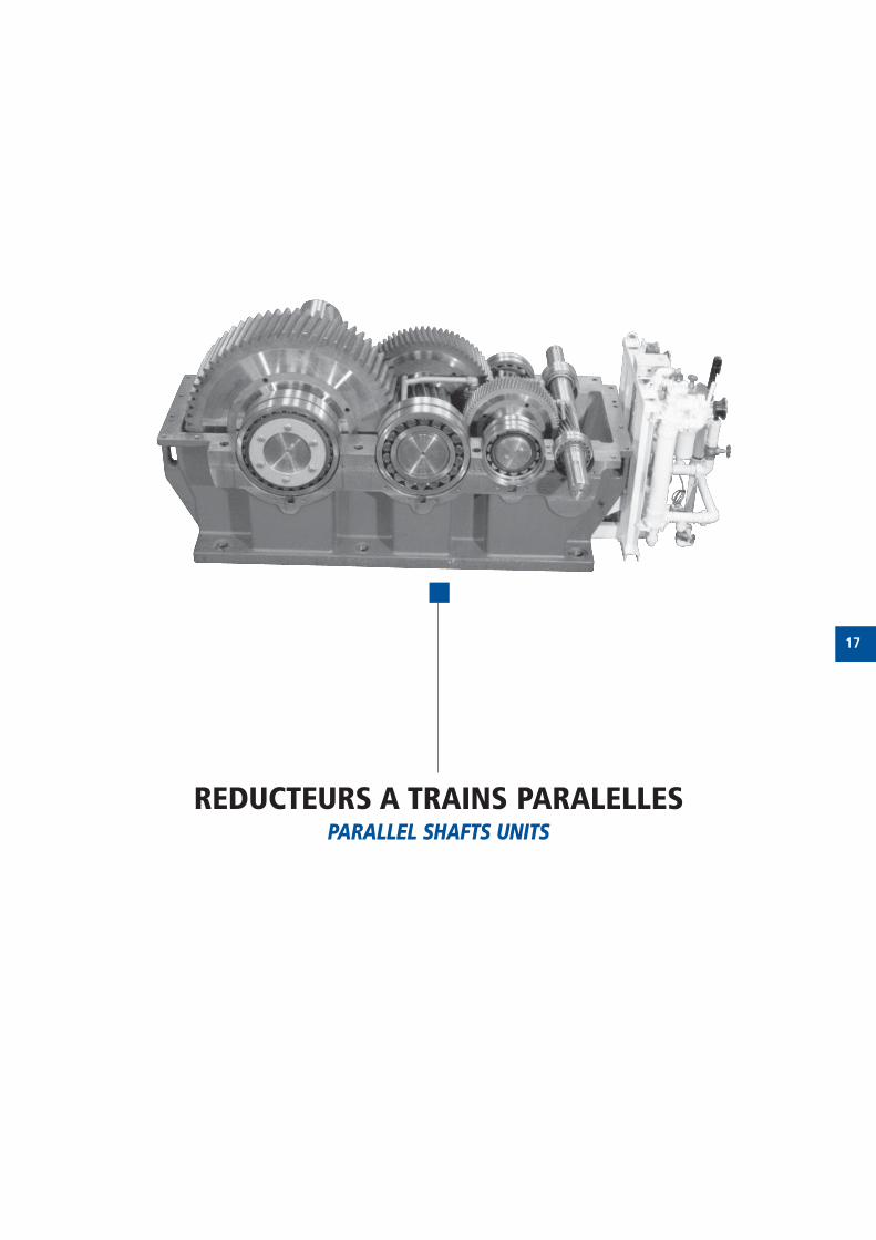
REDUCTEURS A TRAINS PARALELLESPARALLEL SHAFTS UNITS
18
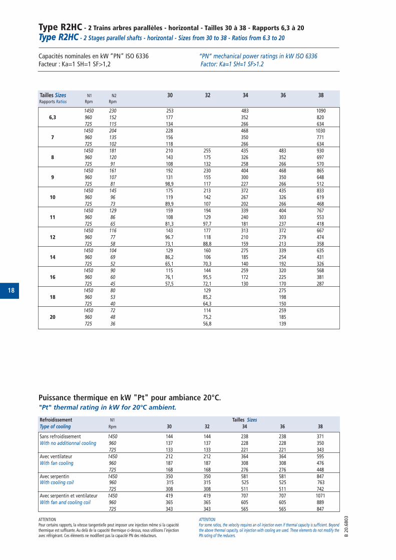
Type R2HC - 2 Trains arbres parallèles - horizontal - Tailles 30 à 38 - Rapports 6,3 à 20
Type R2HC - 2 Stages parallel shafts - horizontal - Sizes from 30 to 38 - Ratios from 6.3 to 20
Capacités nominales en kW “PN” ISO 6336 Facteur : Ka=1 SH=1 SF>1,2
Puissance thermique en kW "Pt" pour ambiance 20°C."Pt" thermal rating in kW for 20°C ambient.
“PN” mechanical power ratings in kW ISO 6336 Factor: Ka=1 SH=1 SF>1.2
ATTENTIONPour certains rapports, la vitesse tangentielle peut imposer une injection même si la capacitéthermique est suffisante. Au delà de la capacité thermique ci-dessus, nous utilisons l'injectionavec réfrigérant. Ces éléments ne modifient pas la capacité PN des réducteurs.
ATTENTIONFor some ratios, the velocity requires an oil injection even if thermal capacity is sufficient. Beyondthe above thermal capacity, oil injection with cooling are used. These elements do not modify thePN rating of the reducers. B
20.6
803
Tailles Sizes N1 N2 30 32 34 36 38Rapports Ratios Rpm Rpm
1450 230 253 483 1090
6,3 960 152 177 352 820
725 115 134 266 634
1450 204 228 468 1030
7 960 135 156 350 771
725 102 118 266 634
1450 181 210 255 435 483 930
8 960 120 143 175 326 352 697
725 91 108 132 258 266 570
1450 161 192 230 404 468 865
9 960 107 131 155 300 350 648
725 81 98,9 117 227 266 512
1450 145 175 213 372 435 833
10 960 96 119 142 267 326 619
725 73 89,9 107 202 266 468
1450 129 159 194 339 404 767
11 960 86 108 129 240 303 553
725 65 81,3 97,7 181 237 418
1450 116 143 177 313 372 667
12 960 77 96.7 118 210 279 474
725 58 73,1 88,8 159 213 358
1450 104 129 160 275 339 635
14 960 69 86,2 106 185 254 431
725 52 65,1 70,3 140 192 326
1450 90 115 144 259 320 568
16 960 60 76,1 95,5 172 225 381
725 45 57,5 72,1 130 170 287
1450 80 129 275
18 960 53 85,2 198
725 40 64,3 150
1450 72 114 259
20 960 48 75,2 185
725 36 56,8 139
Refroidissement N1 Tailles Sizes
Type of cooling Rpm 30 32 34 36 38
Sans refroidissement 1450 144 144 238 238 371
With no additionnal cooling 960 137 137 228 228 350
725 133 133 221 221 343
Avec ventilateur 1450 212 212 364 364 595
With fan cooling 960 187 187 308 308 476
725 168 168 276 276 448
Avec serpentin 1450 350 350 581 581 847With cooling coil 960 315 315 525 525 763
725 308 308 511 511 742
Avec serpentin et ventilateur 1450 419 419 707 707 1071
With fan and cooling coil 960 365 365 605 605 889
725 343 343 565 565 847
19
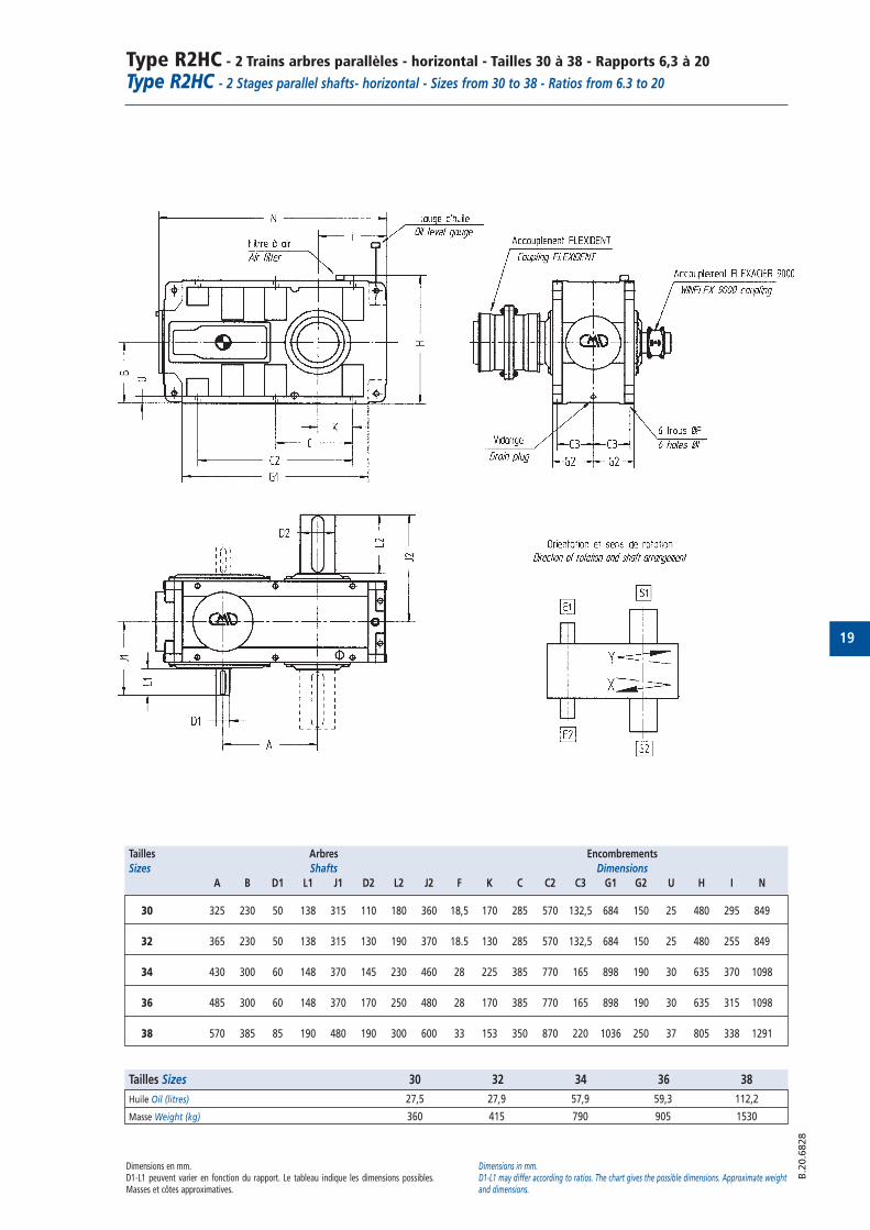
Type R2HC - 2 Trains arbres parallèles - horizontal - Tailles 30 à 38 - Rapports 6,3 à 20
Type R2HC - 2 Stages parallel shafts- horizontal - Sizes from 30 to 38 - Ratios from 6.3 to 20
Dimensions en mm.D1-L1 peuvent varier en fonction du rapport. Le tableau indique les dimensions possibles.Masses et côtes approximatives.
Dimensions in mm.D1-L1 may differ according to ratios. The chart gives the possible dimensions. Approximate weightand dimensions.
B.2
0.6
828
Tailles Arbres Encombrements
Sizes Shafts Dimensions
A B D1 L1 J1 D2 L2 J2 F K C C2 C3 G1 G2 U H I N
30 325 230 50 138 315 110 180 360 18,5 170 285 570 132,5 684 150 25 480 295 849
32 365 230 50 138 315 130 190 370 18.5 130 285 570 132,5 684 150 25 480 255 849
34 430 300 60 148 370 145 230 460 28 225 385 770 165 898 190 30 635 370 1098
36 485 300 60 148 370 170 250 480 28 170 385 770 165 898 190 30 635 315 1098
38 570 385 85 190 480 190 300 600 33 153 350 870 220 1036 250 37 805 338 1291
Tailles Sizes 30 32 34 36 38
Huile Oil (litres) 27,5 27,9 57,9 59,3 112,2
Masse Weight (kg) 360 415 790 905 1530
20
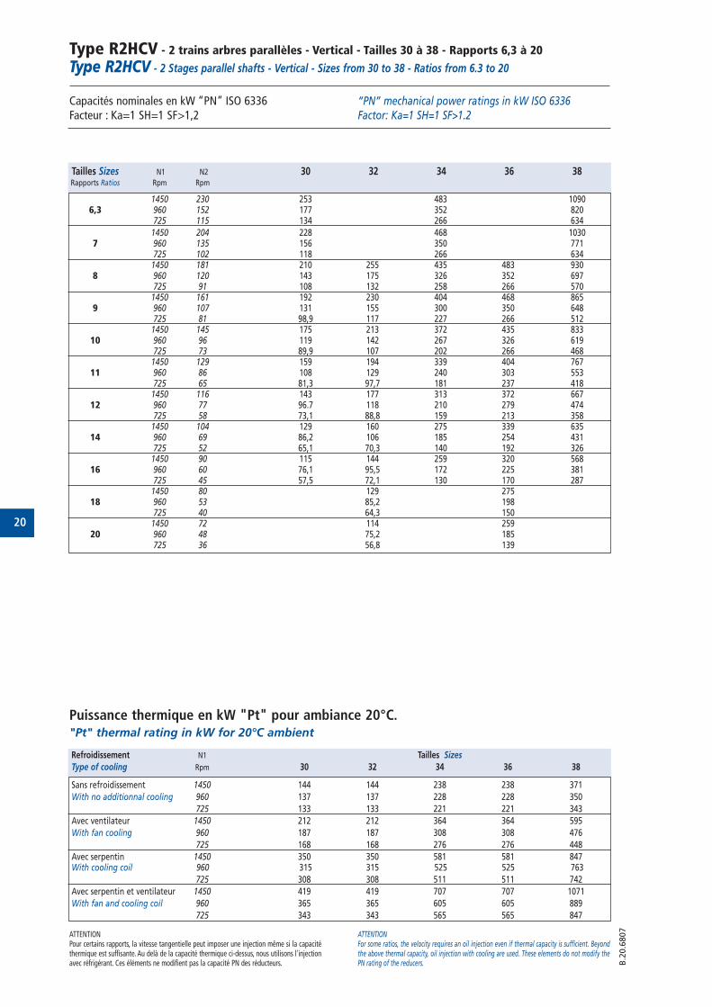
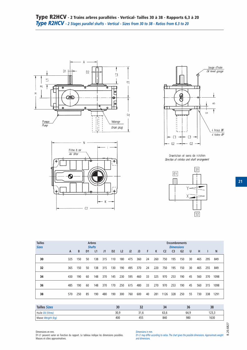
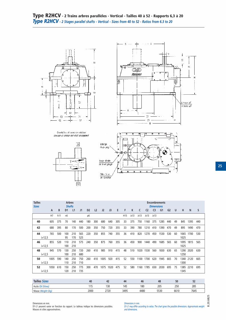
Type R2HCV - 2 trains arbres parallèles - Vertical - Tailles 30 à 38 - Rapports 6,3 à 20
Type R2HCV - 2 Stages parallel shafts - Vertical - Sizes from 30 to 38 - Ratios from 6.3 to 20
Capacités nominales en kW “PN” ISO 6336 Facteur : Ka=1 SH=1 SF>1,2
Puissance thermique en kW "Pt" pour ambiance 20°C."Pt" thermal rating in kW for 20°C ambient
“PN” mechanical power ratings in kW ISO 6336 Factor: Ka=1 SH=1 SF>1.2
ATTENTIONPour certains rapports, la vitesse tangentielle peut imposer une injection même si la capacitéthermique est suffisante. Au delà de la capacité thermique ci-dessus, nous utilisons l'injectionavec réfrigérant. Ces éléments ne modifient pas la capacité PN des réducteurs.
ATTENTIONFor some ratios, the velocity requires an oil injection even if thermal capacity is sufficient. Beyondthe above thermal capacity, oil injection with cooling are used. These elements do not modify thePN rating of the reducers. B
.20.6
807
Tailles Sizes N1 N2 30 32 34 36 38Rapports Ratios Rpm Rpm
1450 230 253 483 10906,3 960 152 177 352 820
725 115 134 266 634
1450 204 228 468 10307 960 135 156 350 771
725 102 118 266 6341450 181 210 255 435 483 930
8 960 120 143 175 326 352 697725 91 108 132 258 266 5701450 161 192 230 404 468 865
9 960 107 131 155 300 350 648725 81 98,9 117 227 266 5121450 145 175 213 372 435 833
10 960 96 119 142 267 326 619725 73 89,9 107 202 266 4681450 129 159 194 339 404 767
11 960 86 108 129 240 303 553725 65 81,3 97,7 181 237 4181450 116 143 177 313 372 667
12 960 77 96.7 118 210 279 474725 58 73,1 88,8 159 213 3581450 104 129 160 275 339 635
14 960 69 86,2 106 185 254 431725 52 65,1 70,3 140 192 3261450 90 115 144 259 320 568
16 960 60 76,1 95,5 172 225 381725 45 57,5 72,1 130 170 2871450 80 129 275
18 960 53 85,2 198725 40 64,3 150
1450 72 114 25920 960 48 75,2 185
725 36 56,8 139
Refroidissement N1 Tailles Sizes
Type of cooling Rpm 30 32 34 36 38
Sans refroidissement 1450 144 144 238 238 371
With no additionnal cooling 960 137 137 228 228 350
725 133 133 221 221 343
Avec ventilateur 1450 212 212 364 364 595
With fan cooling 960 187 187 308 308 476
725 168 168 276 276 448
Avec serpentin 1450 350 350 581 581 847With cooling coil 960 315 315 525 525 763
725 308 308 511 511 742
Avec serpentin et ventilateur 1450 419 419 707 707 1071
With fan and cooling coil 960 365 365 605 605 889
725 343 343 565 565 847
21
Type R2HCV - 2 Trains arbres parallèles - Vertical- Tailles 30 à 38 - Rapports 6,3 à 20
Type R2HCV - 2 Stages parallel shafts - Vertical - Sizes from 30 to 38 - Ratios from 6.3 to 20
Dimensions en mm.D1-L1 peuvent varier en fonction du rapport. Le tableau indique les dimensions possibles.Masses et côtes approximatives.
Dimensions in mm.D1-L1 may differ according to ratios. The chart gives the possible dimensions. Approximate weightand dimensions.
B.2
0.6
827
Tailles Arbres Encombrements
Sizes Shafts Dimensions
A B D1 L1 J1 D2 L2 J2 J3 F K C2 C3 G2 U H I N
30 325 150 50 138 315 110 180 475 360 24 260 750 195 150 30 465 295 849
32 365 150 50 138 315 130 190 495 370 24 220 750 195 150 30 465 255 849
34 430 190 60 148 370 145 230 595 460 33 325 970 253 190 45 560 370 1098
36 485 190 60 148 370 170 250 615 480 33 270 970 253 190 45 560 315 1098
38 570 250 85 190 480 190 300 760 600 40 281 1126 328 250 55 730 338 1291
Tailles Sizes 30 32 34 36 38
Huile Oil (litres) 30,9 31,6 63,6 64,9 123,3
Masse Weight (kg) 400 455 840 980 1630
22
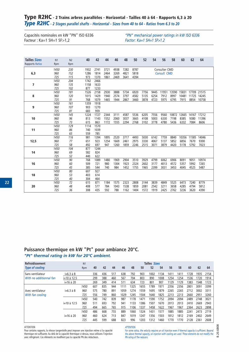
Type R2HC - 2 Trains arbres parallèles - Horizontal - Tailles 40 à 64 - Rapports 6,3 à 20
Type R2HC - 2 Stages parallel shafts - Horizontal - Sizes from 40 to 64 - Ratios from 6.3 to 20
Capacités nominales en kW “PN” ISO 6336 Facteur : Ka=1 SH=1 SF>1,2
Puissance thermique en kW "Pt" pour ambiance 20°C."Pt" thermal rating in kW for 20°C ambient.
“PN” mechanical power ratings in kW ISO 6336 Factor: Ka=1 SH=1 SF>1.2
ATTENTIONPour certains rapports, la vitesse tangentielle peut imposer une injection même si la capacitéthermique est suffisante. Au delà de la capacité thermique ci-dessus, nous utilisons l'injectionavec réfrigérant. Ces éléments ne modifient pas la capacité PN des réducteurs.
ATTENTIONFor some ratios, the velocity requires an oil injection even if thermal capacity is sufficient. Beyondthe above thermal capacity, oil injection with cooling are used. These elements do not modify thePN rating of the reducers. B
.20.6
808
Tailles Sizes N1 N2 40 42 44 46 48 50 52 54 56 58 60 62 64Rapports Ratios Rpm Rpm
1450 230 1932 2741 3721 4938 7282 8787 Consulter CMD6,3 960 152 1286 1814 2464 3269 4821 5818 Consult CMD
725 115 973 1370 1861 2469 3641 43941450 204 1742 2466
7 960 135 1158 1633725 102 877 12331450 181 1526 2158 2930 3888 5734 6920 7756 9445 11951 13590 15831 17709 21515
8 960 120 1015 1429 1940 2574 3797 4582 5135 6254 7912 8997 10481 11725 14245725 91 768 1079 1465 1944 2867 3460 3878 4723 5975 6795 7915 8854 107581450 161 1359 1918
9 960 107 903 1270725 81 683 9591450 145 1224 1727 2344 3111 4587 5536 6205 7556 9560 10872 12665 14167 17212
10 960 96 813 1143 1552 2060 3037 3665 4108 5003 6330 7198 8385 9380 11396725 73 615 863 1172 1555 2294 2768 3102 3778 4780 5436 6332 7084 86061450 129 1114 1570
11 960 86 740 1039725 65 559 7851450 116 981 1394 1895 2520 3717 4493 5030 6142 7759 8840 10356 11585 14046
12,5 960 77 651 923 1254 1669 2461 2975 3330 4067 5137 5852 6856 7670 9300725 58 492 697 947 1260 1859 2246 2515 3071 3879 4420 5178 5792 70231450 104 877 1244
14 960 69 582 824725 52 440 6221450 90 768 1089 1480 1969 2904 3510 3929 4799 6062 6906 8091 9051 10974
16 960 60 509 721 980 1304 1923 2324 2602 3177 4013 4572 5357 5992 7265725 45 385 544 740 984 1452 1755 1965 2399 3031 3453 4045 4525 54871450 80 607 927
18 960 53 403 614725 40 304 4641450 72 615 871 1184 1575 2323 2808 3144 3839 4849 5525 6473 7240 8779
20 960 48 408 577 784 1043 1538 1859 2081 2542 3211 3658 4285 4794 5812725 36 308 435 592 788 1162 1404 1572 1919 2425 2762 3236 3620 4390
Refroidissement N1 Tailles Sizes
Type of cooling Rpm 40 42 44 46 48 50 52 54 56 58 60 62 64
Sans ventilateur i=6.3 à 8 336 436 517 638 792 903 1002 1134 1411 1411 1728 1935 2154
With no additionnal fan i=10 à 12.5 299 388 460 567 704 803 890 1008 1254 1254 1536 1720 1914
i=16 à 20 269 349 414 511 634 723 801 907 1129 1129 1383 1548 1723
1450 607 835 944 1111 1325 1655 1789 1971 2356 2356 2801 3091 3399
Avec ventilateur i=6.3 à 8 960 575 780 891 1059 1274 1559 1695 1879 2265 2265 2712 3002 3311
With fan cooling 725 556 749 860 1029 1245 1504 1640 1825 2213 2213 2660 2951 3260
1450 540 742 839 987 1178 1471 1590 1752 2094 2094 2489 2748 3021
i=10 à 12.5 960 511 693 792 941 1133 1386 1507 1670 2013 2013 2410 2669 2943
725 494 665 765 915 1106 1337 1458 1622 1967 1967 2364 2623 2898
1450 486 668 755 889 1060 1324 1431 1577 1885 1885 2241 2473 2719
i=16 à 20 960 460 624 713 847 1019 1247 1356 1503 1812 1812 2169 2402 2649
725 445 599 688 823 996 1203 1312 1460 1770 1770 2128 2361 2608
23
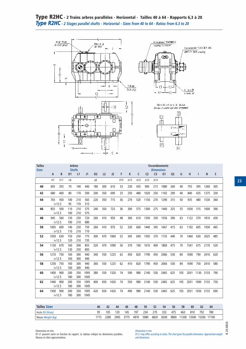
Type R2HC - 2 Trains arbres parallèles - Horizontal - Tailles 40 à 64 - Rapports 6,3 à 20
Type R2HC - 2 Stages parallel shafts - Horizontal - Sizes from 40 to 64 - Ratios from 6.3 to 20
Dimensions en mm.D1-L1 peuvent varier en fonction du rapport. Le tableau indique les dimensions possibles.Masses et côtes approximatives.
Dimensions in mm.D1-L1 may differ according to ratios. The chart gives the possible dimensions. Approximate weightand dimensions.
B.2
0.6
826
Tailles Arbres Encombrements
Sizes Shafts Dimensions
A B D1 L1 J1 D2 L2 J2 F K C C2 C3 G1 G2 U H I N S
H7 h11 n6 p6 H15 Js13 Js13 Js13 Js13
40 605 355 70 140 440 180 300 610 33 230 435 940 215 1080 260 40 755 395 1260 305
42 680 400 80 170 500 200 350 690 33 250 480 1020 250 1165 290 40 840 435 1375 330
44 765 450 100 210 565 220 350 715 36 270 520 1150 270 1290 315 50 935 480 1530 360
i>12.5 95 170 515
46 855 500 110 210 575 240 350 725 36 300 575 1300 275 1440 325 55 1030 515 1690 390
i>12.5 100 210 575
48 945 560 130 250 720 260 410 950 48 300 610 1350 330 1556 396 63 1122 570 1810 430
i>12.5 100 210 680
50 1005 600 140 250 750 260 410 970 52 330 660 1440 345 1667 415 63 1192 605 1930 465
i>12.5 110 210 710
52 1050 630 150 250 775 300 470 1060 52 345 690 1505 370 1735 440 70 1460 630 2025 485
i>12.5 120 210 735
54 1130 670 160 300 855 320 470 1090 56 370 740 1610 400 1860 475 70 1541 675 2170 520
i>12.5 130 250 805
56 1210 750 160 300 940 340 550 1225 62 450 820 1790 450 2066 530 84 1690 790 2410 620
i>12.5 160 300 940
58 1250 750 160 300 940 360 550 1225 62 410 820 1790 450 2066 530 84 1690 750 2410 580
i>12.5 160 300 940
60 1400 900 200 350 1095 380 550 1320 74 590 980 2140 530 2465 625 105 2031 1130 3133 790
i>12.5 180 300 1045
62 1440 900 200 350 1095 400 650 1420 74 550 980 2140 530 2465 625 105 2031 1090 3133 750
i>12.5 180 300 1045
64 1500 900 200 350 1095 420 650 1420 74 490 980 2140 530 2465 625 105 2031 1030 3133 690
i>12.5 180 300 1045
Tailles Sizes 40 42 44 46 48 50 52 54 56 58 60 62 64
Huile Oil (litres) 95 105 120 145 197 234 270 333 475 463 810 792 780
Masse Weight (kg) 1715 2280 2945 3775 4970 5980 6820 8200 9800 11200 13500 15200 17100
24
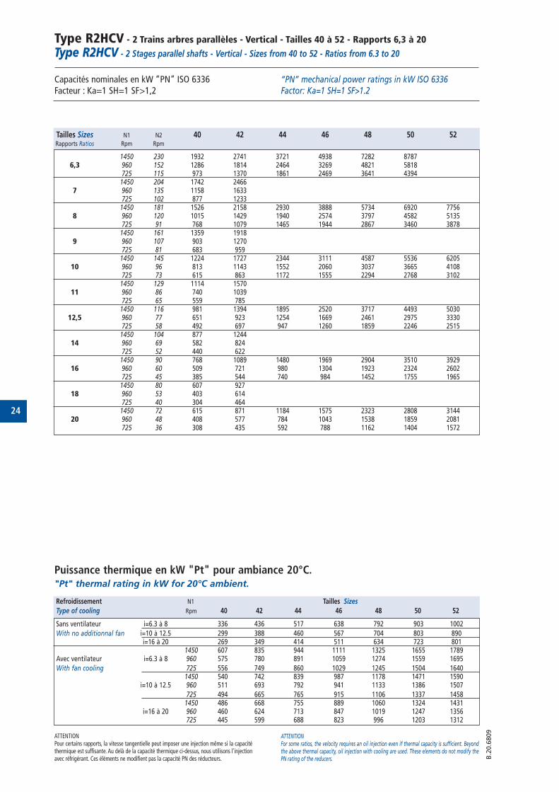
Type R2HCV - 2 Trains arbres parallèles - Vertical - Tailles 40 à 52 - Rapports 6,3 à 20
Type R2HCV - 2 Stages parallel shafts - Vertical - Sizes from 40 to 52 - Ratios from 6.3 to 20
Capacités nominales en kW “PN” ISO 6336 Facteur : Ka=1 SH=1 SF>1,2
Puissance thermique en kW "Pt" pour ambiance 20°C."Pt" thermal rating in kW for 20°C ambient.
“PN” mechanical power ratings in kW ISO 6336 Factor: Ka=1 SH=1 SF>1.2
ATTENTIONPour certains rapports, la vitesse tangentielle peut imposer une injection même si la capacitéthermique est suffisante. Au delà de la capacité thermique ci-dessus, nous utilisons l'injectionavec réfrigérant. Ces éléments ne modifient pas la capacité PN des réducteurs.
ATTENTIONFor some ratios, the velocity requires an oil injection even if thermal capacity is sufficient. Beyondthe above thermal capacity, oil injection with cooling are used. These elements do not modify thePN rating of the reducers. B
.20.6
809
Tailles Sizes N1 N2 40 42 44 46 48 50 52Rapports Ratios Rpm Rpm
1450 230 1932 2741 3721 4938 7282 87876,3 960 152 1286 1814 2464 3269 4821 5818
725 115 973 1370 1861 2469 3641 43941450 204 1742 2466
7 960 135 1158 1633725 102 877 12331450 181 1526 2158 2930 3888 5734 6920 7756
8 960 120 1015 1429 1940 2574 3797 4582 5135725 91 768 1079 1465 1944 2867 3460 38781450 161 1359 1918
9 960 107 903 1270725 81 683 9591450 145 1224 1727 2344 3111 4587 5536 6205
10 960 96 813 1143 1552 2060 3037 3665 4108725 73 615 863 1172 1555 2294 2768 31021450 129 1114 1570
11 960 86 740 1039725 65 559 7851450 116 981 1394 1895 2520 3717 4493 5030
12,5 960 77 651 923 1254 1669 2461 2975 3330725 58 492 697 947 1260 1859 2246 25151450 104 877 1244
14 960 69 582 824725 52 440 6221450 90 768 1089 1480 1969 2904 3510 3929
16 960 60 509 721 980 1304 1923 2324 2602725 45 385 544 740 984 1452 1755 19651450 80 607 927
18 960 53 403 614725 40 304 4641450 72 615 871 1184 1575 2323 2808 3144
20 960 48 408 577 784 1043 1538 1859 2081725 36 308 435 592 788 1162 1404 1572
Refroidissement N1 Tailles Sizes
Type of cooling Rpm 40 42 44 46 48 50 52
Sans ventilateur i=6.3 à 8 336 436 517 638 792 903 1002
With no additionnal fan i=10 à 12.5 299 388 460 567 704 803 890i=16 à 20 269 349 414 511 634 723 801
1450 607 835 944 1111 1325 1655 1789Avec ventilateur i=6.3 à 8 960 575 780 891 1059 1274 1559 1695
With fan cooling 725 556 749 860 1029 1245 1504 16401450 540 742 839 987 1178 1471 1590
i=10 à 12.5 960 511 693 792 941 1133 1386 1507
725 494 665 765 915 1106 1337 14581450 486 668 755 889 1060 1324 1431
i=16 à 20 960 460 624 713 847 1019 1247 1356725 445 599 688 823 996 1203 1312
25
Type R2HCV - 2 Trains arbres parallèles - Vertical - Tailles 40 à 52 - Rapports 6,3 à 20
Type R2HCV - 2 Stages parallel shafts - Vertical - Sizes from 40 to 52 - Ratios from 6.3 to 20
Dimensions en mm.D1-L1 peuvent varier en fonction du rapport. Le tableau indique les dimensions possibles.Masses et côtes approximatives.
Dimensions in mm.D1-L1 may differ according to ratios. The chart gives the possible dimensions. Approximate weightand dimensions.
B.2
0.6
825
Tailles Arbres Encombrements
Sizes Shafts Dimensions
A B D1 L1 J1 D2 L2 J2 J3 E F K C C2 C3 G1 G2 U H N S
H7 h11 n6 p6 H15 Js13 Js13 Js13 Js13
40 605 375 70 140 440 180 300 680 640 305 33 375 750 1160 375 1285 440 49 845 1395 440
42 680 395 80 170 500 200 350 750 720 355 33 390 780 1210 410 1390 470 49 895 1490 470
44 765 500 100 210 565 220 350 855 740 355 36 410 820 1270 450 1530 530 60 1065 1700 530
i>12,5 95 170 525 1025
46 855 520 110 210 575 240 350 875 760 355 36 450 900 1440 490 1685 565 60 1095 1815 565
i>12,5 100 210 1025
48 945 570 130 250 720 260 410 985 910 415 48 510 1020 1530 560 1830 630 65 1290 2020 630
i>12,5 100 210 680 1250
50 1005 590 140 250 750 260 410 1005 920 415 52 550 1100 1700 620 1945 665 70 1340 2120 665
i>12,5 110 210 710 1300
52 1050 610 150 250 775 300 470 1075 1020 475 52 580 1160 1785 650 2030 695 75 1385 2210 695
i>12,5 120 210 735 1345
Tailles Sizes 40 42 44 46 48 50 52
Huile Oil (litres) 115 130 145 180 205 250 285
Masse Weight (kg) 2000 2720 3495 4480 5530 6610 7645
26
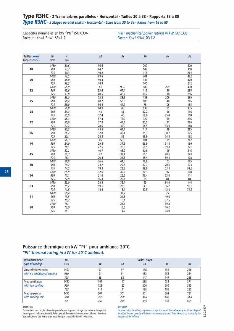
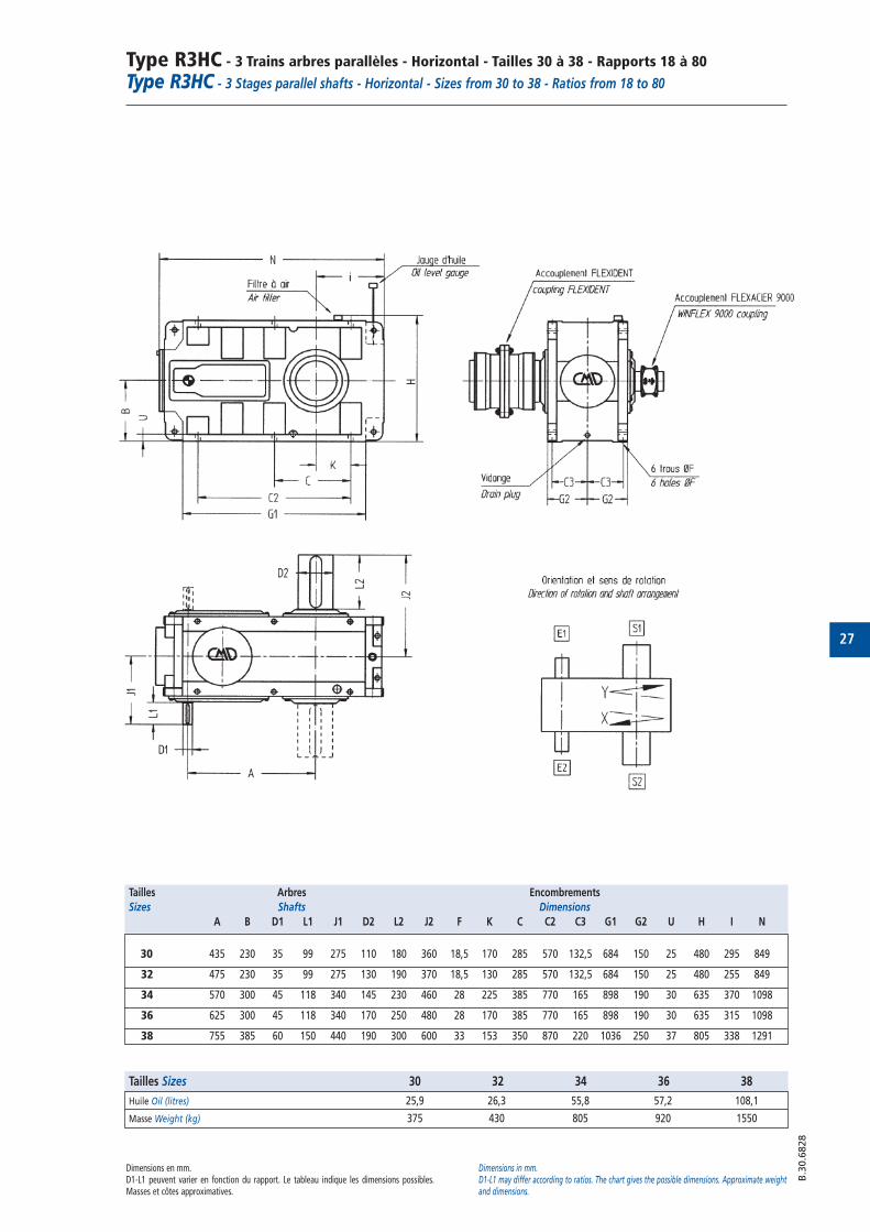
Type R3HC - 3 Trains arbres parallèles - Horizontal - Tailles 30 à 38 - Rapports 18 à 80
Type R3HC - 3 Stages parallel shafts - Horizontal - Sizes from 30 to 38 - Ratios from 18 to 80
Capacités nominales en kW “PN” ISO 6336 Facteur : Ka=1 SH=1 SF>1,2
Puissance thermique en kW "Pt" pour ambiance 20°C."Pt" thermal rating in kW for 20°C ambient.
“PN” mechanical power ratings in kW ISO 6336 Factor: Ka=1 SH=1 SF>1.2
ATTENTIONPour certains rapports, la vitesse tangentielle peut imposer une injection même si la capacitéthermique est suffisante. Au delà de la capacité thermique ci-dessus, nous utilisons l'injectionavec réfrigérant. Ces éléments ne modifient pas la capacité PN des réducteurs.
ATTENTIONFor some ratios, the velocity requires an oil injection even if thermal capacity is sufficient. Beyondthe above thermal capacity, oil injection with cooling are used. These elements do not modify thePN rating of the reducers. B
.30.6
807
Tailles Sizes N1 N2 30 32 34 36 38Rapports Ratios Rpm Rpm
1450 80,6 96,6 209 50018 960 53,3 64,7 149 350
725 40,3 49,2 113 2641450 72,5 89,6 201 482
20 960 48,0 59,3 133 320725 36,3 44,8 100 242
1450 65,9 81 96,6 180 209 43022 960 43,6 53,6 64,4 119 156 285
725 33,0 40,5 48,7 90,2 118 2161450 58,0 72,8 88,5 158 209 369
25 960 38,4 48,2 58,6 105 140 245725 29,0 36,4 44,2 79 106 185
1450 51,8 64,9 80 139 191 33528 960 34,3 43 53 92,2 126 196
725 25,9 32,4 40 69,6 95,4 1681450 45,3 57,3 71,9 129 169 296
32 960 30,0 37,9 47,6 85,5 112 296725 22,7 28,6 35,9 64,5 84,3 148
1450 40,3 49,5 64,1 114 149 26536 960 26,7 32,8 42,4 75,3 98,7 175
725 20,1 24,8 32 56,9 74,5 1321450 36,3 45 56,6 101 139 242
40 960 24,0 29,8 37,5 66,9 91,8 160725 18,1 22,5 28,3 50,5 69,3 121
1450 32,2 40,7 48,9 90,8 119 21645 960 21,3 27 32,4 60,1 78,5 143
725 16,1 20,4 24,5 45,4 59,3 1081450 29,0 36,6 44,5 79,6 107 185
50 960 19,2 24,2 29,4 52,7 70,5 123725 14,5 18,3 22,2 39,8 53,3 92,5
1450 25,9 32,6 40,2 70,1 96 16856 960 17,1 21,6 26,6 46,4 63,6 111
725 12,9 16,3 20,1 35 48 841450 23,0 28,8 36,1 65 84,9 148
63 960 15,2 19,1 23,9 43 56,2 98,3725 11,5 14,4 18,1 32,5 42,4 74,2
1450 20,4 32,2 7571 960 13,5 21,3 49,6
725 10,2 16,1 37,51450 18,1 28,5 69,8
80 960 12,0 18,8 46,2725 9,1 14,2 34,9
Refroidissement N1 Tailles Sizes
Type of cooling Rpm 30 32 34 36 38
Sans refroidissement 1450 97 97 158 158 248
With no additionnal cooling 960 91 91 153 153 234
725 88 88 147 147 228
Avec ventilateur 1450 147 147 238 238 371
With fan cooling 960 123 123 206 206 315
725 111 111 185 185 285
Avec serpentin 1450 301 301 501 501 721With cooling coil 960 269 269 445 445 644
725 259 259 434 434 609
27
Type R3HC - 3 Trains arbres parallèles - Horizontal - Tailles 30 à 38 - Rapports 18 à 80
Type R3HC - 3 Stages parallel shafts - Horizontal - Sizes from 30 to 38 - Ratios from 18 to 80
Dimensions en mm.D1-L1 peuvent varier en fonction du rapport. Le tableau indique les dimensions possibles.Masses et côtes approximatives.
Dimensions in mm.D1-L1 may differ according to ratios. The chart gives the possible dimensions. Approximate weightand dimensions.
B.3
0.6
828
Tailles Arbres Encombrements
Sizes Shafts Dimensions
A B D1 L1 J1 D2 L2 J2 F K C C2 C3 G1 G2 U H I N
30 435 230 35 99 275 110 180 360 18,5 170 285 570 132,5 684 150 25 480 295 849
32 475 230 35 99 275 130 190 370 18,5 130 285 570 132,5 684 150 25 480 255 849
34 570 300 45 118 340 145 230 460 28 225 385 770 165 898 190 30 635 370 1098
36 625 300 45 118 340 170 250 480 28 170 385 770 165 898 190 30 635 315 1098
38 755 385 60 150 440 190 300 600 33 153 350 870 220 1036 250 37 805 338 1291
Tailles Sizes 30 32 34 36 38
Huile Oil (litres) 25,9 26,3 55,8 57,2 108,1
Masse Weight (kg) 375 430 805 920 1550

28
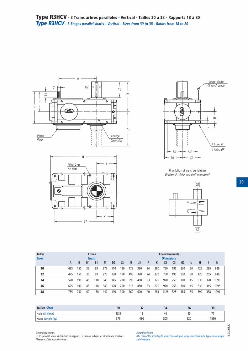
Type R3HCV - 3 Trains arbres parallèles - Vertical - Tailles 30 à 38 - Rapports 18 à 80
Type R3HCV - 3 Stages parallel shafts - Vertical - Sizes from 30 to 38 - Ratios from 18 to 80
Capacités nominales en kW “PN” ISO 6336 Facteur : Ka=1 SH=1 SF>1,2
Puissance thermique en kW "Pt" pour ambiance 20°C."Pt" thermal rating in kW for 20°C ambient.
“PN” mechanical power ratings in kW ISO 6336 Factor: Ka=1 SH=1 SF>1.2
ATTENTIONPour certains rapports, la vitesse tangentielle peut imposer une injection même si la capacitéthermique est suffisante. Au delà de la capacité thermique ci-dessus, nous utilisons l'injectionavec réfrigérant. Ces éléments ne modifient pas la capacité PN des réducteurs.
ATTENTIONFor some ratios, the velocity requires an oil injection even if thermal capacity is sufficient. Beyondthe above thermal capacity, oil injection with cooling are used. These elements do not modify thePN rating of the reducers. B
.30.6
808
Tailles Sizes N1 N2 30 32 34 36 38Rapports Ratios Rpm Rpm
1450 80,6 96,6 209 50018 960 53,3 64,7 149 350
725 40,3 49,2 113 2641450 72,5 89,6 201 482
20 960 48,0 59,3 133 320725 36,3 44,8 100 242
1450 65,9 81 96,6 180 209 43022 960 43,6 53,6 64,4 119 156 285
725 33,0 40,5 48,7 90,2 118 2161450 58,0 72,8 88,5 158 209 369
25 960 38,4 48,2 58,6 105 140 245725 29,0 36,4 44,2 79 106 185
1450 51,8 64,9 80 139 191 33528 960 34,3 43 53 92,2 126 196
725 25,9 32,4 40 69,6 95,4 1681450 45,3 57,3 71,9 129 169 296
32 960 30,0 37,9 47,6 85,5 112 296725 22,7 28,6 35,9 64,5 84,3 148
1450 40,3 49,5 64,1 114 149 26536 960 26,7 32,8 42,4 75,3 98,7 175
725 20,1 24,8 32 56,9 74,5 1321450 36,3 45 56,6 101 139 242
40 960 24,0 29,8 37,5 66,9 91,8 160725 18,1 22,5 28,3 50,5 69,3 121
1450 32,2 40,7 48,9 90,8 119 21645 960 21,3 27 32,4 60,1 78,5 143
725 16,1 20,4 24,5 45,4 59,3 1081450 29,0 36,6 44,5 79,6 107 185
50 960 19,2 24,2 29,4 52,7 70,5 123725 14,5 18,3 22,2 39,8 53,3 92,5
1450 25,9 32,6 40,2 70,1 96 16856 960 17,1 21,6 26,6 46,4 63,6 111
725 12,9 16,3 20,1 35 48 841450 23,0 28,8 36,1 65 84,9 148
63 960 15,2 19,1 23,9 43 56,2 98,3725 11,5 14,4 18,1 32,5 42,4 74,2
1450 20,4 32,2 7571 960 13,5 21,3 49,6
725 10,2 16,1 37,51450 18,1 28,5 69,8
80 960 12,0 18,8 46,2725 9,1 14,2 34,9
Refroidissement N1 Tailles Sizes
Type of cooling Rpm 30 32 34 36 38
Sans refroidissement 1450 97 97 158 158 248
With no additionnal cooling 960 91 91 153 153 234
725 88 88 147 147 228
Avec ventilateur 1450 147 147 238 238 371
With fan cooling 960 123 123 206 206 315
725 111 111 185 185 285
Avec serpentin 1450 301 301 501 501 721With cooling coil 960 269 269 445 445 644
725 259 259 434 434 609
29
Type R3HCV - 3 Trains arbres parallèles - Vertical - Tailles 30 à 38 - Rapports 18 à 80
Type R3HCV - 3 Stages parallel shafts - Vertical - Sizes from 30 to 38 - Ratios from 18 to 80
Dimensions en mm.D1-L1 peuvent varier en fonction du rapport. Le tableau indique les dimensions possibles.Masses et côtes approximatives.
Dimensions in mm.D1-L1 may differ according to ratios. The chart gives the possible dimensions. Approximate weightand dimensions.
B.3
0.6
827
Tailles Arbres Encombrements
Sizes Shafts Dimensions
A B D1 L1 J1 D2 L2 J2 J3 F K C2 C3 G2 U H I N
30 435 150 35 99 275 110 180 475 360 24 260 750 195 230 30 425 295 849
32 475 150 35 99 275 130 190 495 370 24 220 750 195 230 30 425 255 849
34 570 190 45 118 340 145 230 595 460 33 325 970 253 300 45 530 370 1098
36 625 190 45 118 340 170 250 615 480 33 270 970 253 300 45 530 315 1098
38 755 250 60 150 440 190 300 760 600 40 281 1126 328 385 55 690 338 1291
Tailles Sizes 30 32 34 36 38
Huile Oil (litres) 18,5 19 40 40 77
Masse Weight (kg) 375 430 805 920 1550
30
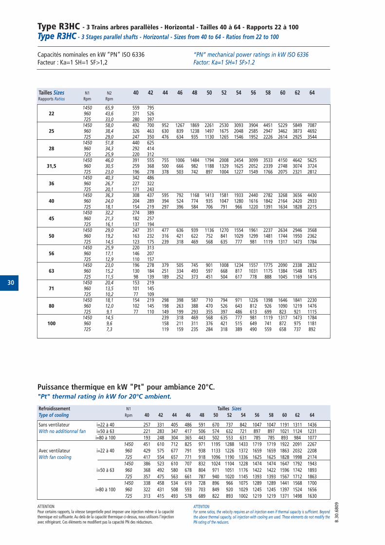
Type R3HC - 3 Trains arbres parallèles - Horizontal - Tailles 40 à 64 - Rapports 22 à 100Type R3HC - 3 Stages parallel shafts - Horizontal - Sizes from 40 to 64 - Ratios from 22 to 100
Capacités nominales en kW “PN” ISO 6336 Facteur : Ka=1 SH=1 SF>1,2
Puissance thermique en kW "Pt" pour ambiance 20°C."Pt" thermal rating in kW for 20°C ambient.
“PN” mechanical power ratings in kW ISO 6336 Factor: Ka=1 SH=1 SF>1.2
ATTENTIONPour certains rapports, la vitesse tangentielle peut imposer une injection même si la capacitéthermique est suffisante. Au delà de la capacité thermique ci-dessus, nous utilisons l'injectionavec réfrigérant. Ces éléments ne modifient pas la capacité PN des réducteurs.
ATTENTIONFor some ratios, the velocity requires an oil injection even if thermal capacity is sufficient. Beyondthe above thermal capacity, oil injection with cooling are used. These elements do not modify thePN rating of the reducers. B
.30.6
809
Tailles Sizes N1 N2 40 42 44 46 48 50 52 54 56 58 60 62 64Rapports Ratios Rpm Rpm
1450 65,9 559 79522 960 43,6 371 526
725 33,0 280 3971450 58,0 492 700 952 1267 1869 2261 2530 3093 3904 4451 5229 5849 7087
25 960 38,4 326 463 630 839 1238 1497 1675 2048 2585 2947 3462 3873 4692725 29,0 247 350 476 634 935 1130 1265 1546 1952 2226 2614 2925 35441450 51,8 440 625
28 960 34,3 292 414725 25,9 220 3121450 46,0 391 555 755 1006 1484 1794 2008 2454 3099 3533 4150 4642 5625
31,5 960 30,5 259 368 500 666 982 1188 1329 1625 2052 2339 2748 3074 3724725 23,0 196 278 378 503 742 897 1004 1227 1549 1766 2075 2321 28121450 40,3 342 486
36 960 26,7 227 322725 20,1 171 2431450 36,3 308 437 595 792 1168 1413 1581 1933 2440 2782 3268 3656 4430
40 960 24,0 204 289 394 524 774 935 1047 1280 1616 1842 2164 2420 2933725 18,1 154 219 297 396 584 706 791 966 1220 1391 1634 1828 22151450 32,2 274 389
45 960 21,3 182 257725 16,1 137 1941450 29,0 247 351 477 636 939 1136 1270 1554 1961 2237 2634 2946 3568
50 960 19,2 163 232 316 421 622 752 841 1029 1299 1481 1744 1950 2362725 14,5 123 175 239 318 469 568 635 777 981 1119 1317 1473 17841450 25,9 220 313
56 960 17,1 146 207725 12,9 110 1571450 23,0 196 278 379 505 745 901 1008 1234 1557 1775 2090 2338 2832
63 960 15,2 130 184 251 334 493 597 668 817 1031 1175 1384 1548 1875725 11,5 98 139 189 252 373 451 504 617 778 888 1045 1169 14161450 20,4 153 219
71 960 13,5 101 145725 10,2 77 1091450 18,1 154 219 298 398 587 710 794 971 1226 1398 1646 1841 2230
80 960 12,0 102 145 198 263 388 470 526 643 812 926 1090 1219 1476725 9,1 77 110 149 199 293 355 397 486 613 699 823 921 11151450 14,5 239 318 469 568 635 777 981 1119 1317 1473 1784
100 960 9,6 158 211 311 376 421 515 649 741 872 975 1181725 7,3 119 159 235 284 318 389 490 559 658 737 892
Refroidissement N1 Tailles Sizes
Type of cooling Rpm 40 42 44 46 48 50 52 54 56 58 60 62 64
Sans ventilateur i=22 à 40 257 331 405 486 591 670 737 842 1047 1047 1191 1311 1436
With no additionnal fan i=50 à 63 221 283 347 417 506 574 632 721 897 897 1021 1124 1231
i=80 à 100 193 248 304 365 443 502 553 631 785 785 893 984 1077
1450 451 610 712 825 971 1195 1288 1433 1719 1719 1922 2091 2267
Avec ventilateur i=22 à 40 960 429 575 677 791 938 1133 1226 1372 1659 1659 1863 2032 2208
With fan cooling 725 417 554 657 771 918 1096 1190 1336 1625 1625 1828 1998 2174
1450 386 523 610 707 832 1024 1104 1228 1474 1474 1647 1792 1943
i=50 à 63 960 368 492 580 678 804 971 1051 1176 1422 1422 1596 1742 1893
725 357 475 563 661 787 940 1020 1145 1393 1393 1567 1712 1863
1450 338 458 534 619 728 896 966 1075 1289 1289 1441 1568 1700
i=80 à 100 960 322 431 508 593 703 849 920 1029 1245 1245 1397 1524 1656
725 313 415 493 578 689 822 893 1002 1219 1219 1371 1498 1630
31
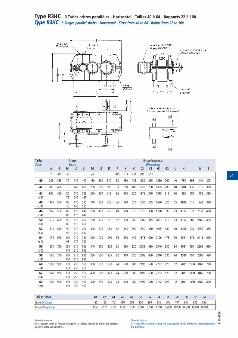
Type R3HC - 3 Trains arbres parallèles - Horizontal - Tailles 40 à 64 - Rapports 22 à 100Type R3HC - 3 Stages parallel shafts - Horizontal - Sizes from 40 to 64 - Ratios from 22 to 100
Dimensions en mm.D1-L1 peuvent varier en fonction du rapport. Le tableau indique les dimensions possibles.Masses et côtes approximatives.
Dimensions in mm.D1-L1 may differ according to ratios. The chart gives the possible dimensions. Approximate weightand dimensions.
B.3
0.6
826
Tailles Arbres Encombrements
Sizes Shafts Dimensions
A B D1 L1 J1 D2 L2 J2 F K C C2 C3 G1 G2 U H I N S
H7 h11 n6 p6 H15 Js13 Js13 Js13 Js13
40 785 355 70 140 440 180 300 610 33 230 435 1120 215 1260 260 40 755 395 1440 305
42 880 400 75 140 470 200 350 690 33 250 480 1220 250 1365 290 40 840 435 1575 330
44 990 450 80 170 525 220 350 715 36 270 520 1375 270 1515 315 50 935 480 1755 360
i>40 75 140 495
46 1105 500 80 170 535 240 350 725 36 300 575 1550 275 1690 325 55 1030 515 1940 390
i>40 75 140 505
48 1205 560 80 170 640 260 410 950 48 300 610 1575 330 1770 396 63 1122 570 2032 430
i>40 80 170 640
50 1275 600 90 170 660 260 410 970 52 330 660 1685 345 1887 415 63 1192 605 2166 465
i>40 80 170 660
52 1330 630 90 170 690 300 470 1060 52 345 690 1750 370 1965 440 70 1460 630 2255 485
i>40 90 170 690
54 1430 670 100 210 760 320 470 1090 56 370 740 1875 400 2106 475 70 1541 675 2416 520
i>40 95 170 720
56 1550 750 120 210 815 340 550 1225 62 450 820 2085 450 2340 530 84 1691 790 2685 620
i>40 110 210 815
58 1590 750 120 210 815 360 550 1225 62 410 820 2085 450 2340 530 84 1530 750 2685 580
i>40 110 210 815
60 1800 900 130 250 950 380 550 1320 74 590 980 2490 530 2792 625 105 2031 1130 3460 790
i>40 130 250 950
62 1840 900 130 250 950 400 650 1420 74 550 980 2490 530 2792 625 105 2031 1090 3460 750
i>40 130 250 950
64 1900 900 130 250 950 420 650 1420 74 490 980 2490 530 2792 625 105 2031 1030 3460 690
i>40 130 250 950
Tailles Sizes 40 42 44 46 48 50 52 54 56 58 60 62 64
Huile Oil (litres) 125 135 142 188 208 250 289 355 505 494 860 845 832
Masse Weight (kg) 1950 2575 3315 4250 5250 6270 7250 8700 10400 11900 14500 16300 18200
32
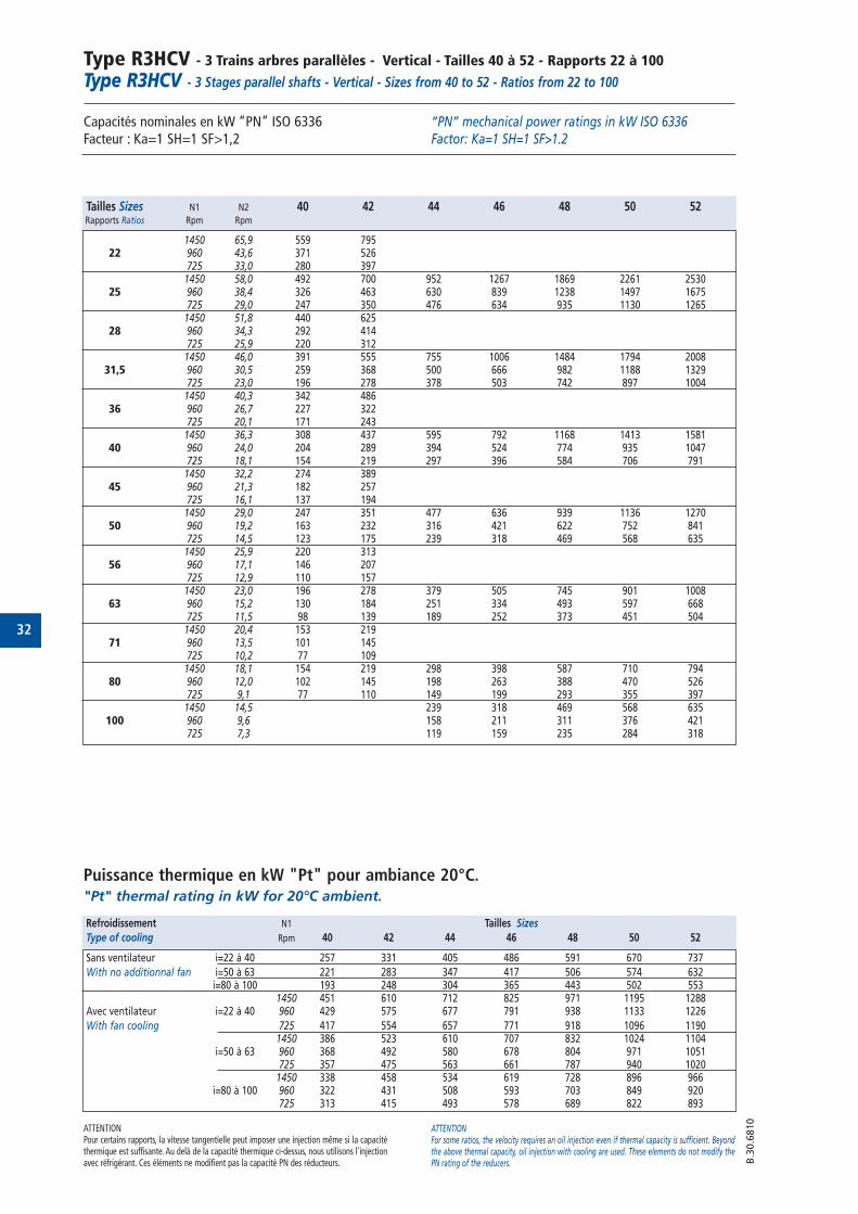
Type R3HCV - 3 Trains arbres parallèles - Vertical - Tailles 40 à 52 - Rapports 22 à 100Type R3HCV - 3 Stages parallel shafts - Vertical - Sizes from 40 to 52 - Ratios from 22 to 100
Capacités nominales en kW “PN” ISO 6336 Facteur : Ka=1 SH=1 SF>1,2
Puissance thermique en kW "Pt" pour ambiance 20°C."Pt" thermal rating in kW for 20°C ambient.
“PN” mechanical power ratings in kW ISO 6336 Factor: Ka=1 SH=1 SF>1.2
ATTENTIONPour certains rapports, la vitesse tangentielle peut imposer une injection même si la capacitéthermique est suffisante. Au delà de la capacité thermique ci-dessus, nous utilisons l'injectionavec réfrigérant. Ces éléments ne modifient pas la capacité PN des réducteurs.
ATTENTIONFor some ratios, the velocity requires an oil injection even if thermal capacity is sufficient. Beyondthe above thermal capacity, oil injection with cooling are used. These elements do not modify thePN rating of the reducers. B
.30.6
810
Tailles Sizes N1 N2 40 42 44 46 48 50 52Rapports Ratios Rpm Rpm
1450 65,9 559 79522 960 43,6 371 526
725 33,0 280 3971450 58,0 492 700 952 1267 1869 2261 2530
25 960 38,4 326 463 630 839 1238 1497 1675725 29,0 247 350 476 634 935 1130 12651450 51,8 440 625
28 960 34,3 292 414725 25,9 220 3121450 46,0 391 555 755 1006 1484 1794 2008
31,5 960 30,5 259 368 500 666 982 1188 1329725 23,0 196 278 378 503 742 897 10041450 40,3 342 486
36 960 26,7 227 322725 20,1 171 2431450 36,3 308 437 595 792 1168 1413 1581
40 960 24,0 204 289 394 524 774 935 1047725 18,1 154 219 297 396 584 706 7911450 32,2 274 389
45 960 21,3 182 257725 16,1 137 1941450 29,0 247 351 477 636 939 1136 1270
50 960 19,2 163 232 316 421 622 752 841725 14,5 123 175 239 318 469 568 6351450 25,9 220 313
56 960 17,1 146 207725 12,9 110 1571450 23,0 196 278 379 505 745 901 1008
63 960 15,2 130 184 251 334 493 597 668725 11,5 98 139 189 252 373 451 5041450 20,4 153 219
71 960 13,5 101 145725 10,2 77 1091450 18,1 154 219 298 398 587 710 794
80 960 12,0 102 145 198 263 388 470 526725 9,1 77 110 149 199 293 355 3971450 14,5 239 318 469 568 635
100 960 9,6 158 211 311 376 421725 7,3 119 159 235 284 318
Refroidissement N1 Tailles Sizes
Type of cooling Rpm 40 42 44 46 48 50 52
Sans ventilateur i=22 à 40 257 331 405 486 591 670 737
With no additionnal fan i=50 à 63 221 283 347 417 506 574 632i=80 à 100 193 248 304 365 443 502 553
1450 451 610 712 825 971 1195 1288Avec ventilateur i=22 à 40 960 429 575 677 791 938 1133 1226
With fan cooling 725 417 554 657 771 918 1096 11901450 386 523 610 707 832 1024 1104
i=50 à 63 960 368 492 580 678 804 971 1051725 357 475 563 661 787 940 10201450 338 458 534 619 728 896 966
i=80 à 100 960 322 431 508 593 703 849 920725 313 415 493 578 689 822 893
33
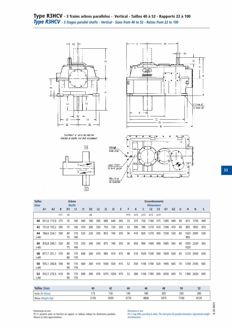
Type R3HCV - 3 Trains arbres parallèles - Vertical - Tailles 40 à 52 - Rapports 22 à 100Type R3HCV - 3 Stages parallel shafts - Vertical - Sizes from 40 to 52 - Ratios from 22 to 100
Dimensions en mm.D1-L1 peuvent varier en fonction du rapport. Le tableau indique les dimensions possibles.Masses et côtes approximatives.
Dimensions in mm.D1-L1 may differ according to ratios. The chart gives the possible dimensions. Approximate weightand dimensions.
B.3
0.6
825
Tailles Arbres Encombrements
Sizes Shafts Dimensions
A1 A2 B D1 L1 J1 D2 L2 J2 J3 E F K C C2 C3 G1 G2 U H N S
h11 n6 p6 H15 Js13 Js13 Js13 Js13
40 651,6 173,9 375 70 140 440 180 300 680 640 305 33 375 750 1160 375 1285 440 49 815 1750 440
42 731,8 193,2 395 75 140 470 200 350 750 720 355 33 390 780 1210 410 1390 470 49 865 1855 470
44 784,6 224,1 500 80 170 525 220 350 855 740 355 36 410 820 1270 450 1530 530 60 1025 2095 530
i>40 75 140 995
46 876,8 249,1 520 80 170 535 240 350 875 760 355 36 450 900 1440 490 1685 565 60 1055 2220 565
i>40 75 140 1025
48 877,7 251,1 570 80 170 640 260 410 985 910 415 48 510 1020 1530 560 1830 630 65 1210 2450 630
i>40 80 170
50 935,1 260,8 590 90 170 660 260 410 1005 920 415 52 550 1100 1700 620 1945 665 70 1250 2545 665
i>40 90 170
52 932,5 270,5 610 90 170 690 300 470 1075 1020 475 52 580 1160 1785 650 2030 695 75 1300 2620 695
i>40 90 170
Tailles Sizes 40 42 44 46 48 50 52
Huile Oil (litres) 115 130 145 180 205 250 285
Masse Weight (kg) 2150 2930 3770 4800 5975 7100 8120
34
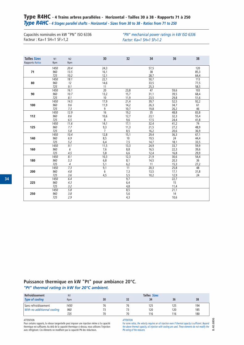
Type R4HC - 4 Trains arbres parallèles - Horizontal - Tailles 30 à 38 - Rapports 71 à 250Type R4HC - 4 Stages parallel shafts - Horizontal - Sizes from 30 to 38 - Ratios from 71 to 250
Capacités nominales en kW “PN” ISO 6336 Facteur : Ka=1 SH=1 SF>1,2
Puissance thermique en kW "Pt" pour ambiance 20°C."Pt" thermal rating in kW for 20°C ambient.
“PN” mechanical power ratings in kW ISO 6336
Factor: Ka=1 SH=1 SF>1.2
ATTENTIONPour certains rapports, la vitesse tangentielle peut imposer une injection même si la capacitéthermique est suffisante. Au delà de la capacité thermique ci-dessus, nous utilisons l'injectionavec réfrigérant. Ces éléments ne modifient pas la capacité PN des réducteurs.
ATTENTIONFor some ratios, the velocity requires an oil injection even if thermal capacity is sufficient. Beyondthe above thermal capacity, oil injection with cooling are used. These elements do not modify thePN rating of the reducers. B
.40.6
806
Tailles Sizes N1 N2 30 32 34 36 38Rapports Ratios Rpm Rpm
1450 20.4 24,3 57,5 12071 960 13.5 16,1 38 85,3
725 10.2 12,1 28,7 64,41450 18.1 22,1 50,7 113
80 960 12 14,6 33,5 77,5725 9.1 11 25,3 58,5
1450 16.1 20 23,8 47 59,6 10390 960 10.7 13,2 15,7 31,1 39,5 68,4
725 8.1 10 11,9 23,5 29,8 51,61450 14.5 17,9 21,4 39,7 52,5 92,2
100 960 9.6 11,9 14,2 26,3 34,7 61725 7.3 9 10,7 19,8 26,2 461450 12.9 16 19,2 35 48,8 83,8
112 960 8.6 10,6 12,7 23,1 32,3 55,4725 6.5 8 9,6 17,5 24,4 41,81450 11.6 14,1 17,1 32,4 41,2 74
125 960 7.7 9,3 11,3 21,5 27,2 48,9725 5.8 7 8,5 16,2 20,6 36,91450 10.4 12,8 15,1 29,4 36,3 67,1
140 960 6.9 8,5 10 19,5 24 44,4725 5.2 6,4 7,5 14,7 18,1 33,51450 9.1 11,5 13,3 24,9 33,7 59,9
160 960 6 7,6 8,8 16,5 22,3 39,6725 4.5 5,8 6,6 12,4 16,8 29,91450 8.1 10,3 12,3 21,9 30,6 54,4
180 960 5.3 6,8 8,1 14,5 20,3 36725 4 5,1 6,2 11 15,3 27,21450 7.3 9,1 11 20,3 25,8 48
200 960 4.8 6 7,3 13,5 17,1 31,8725 3.6 4,5 5,5 10,2 12,9 241450 6.4 9,7 22,7
225 960 4.3 6,4 15725 3.2 4,8 11,41450 5.8 8,5 21,1
250 960 3.8 5,6 14725 2.9 4,3 10,6
Refroidissement N1 Tailles Sizes
Type of cooling Rpm 30 32 34 36 38
Sans refroidissement 1450 76 76 125 125 194
With no additionnal cooling 960 73 73 120 120 185
725 70 70 116 116 180
35
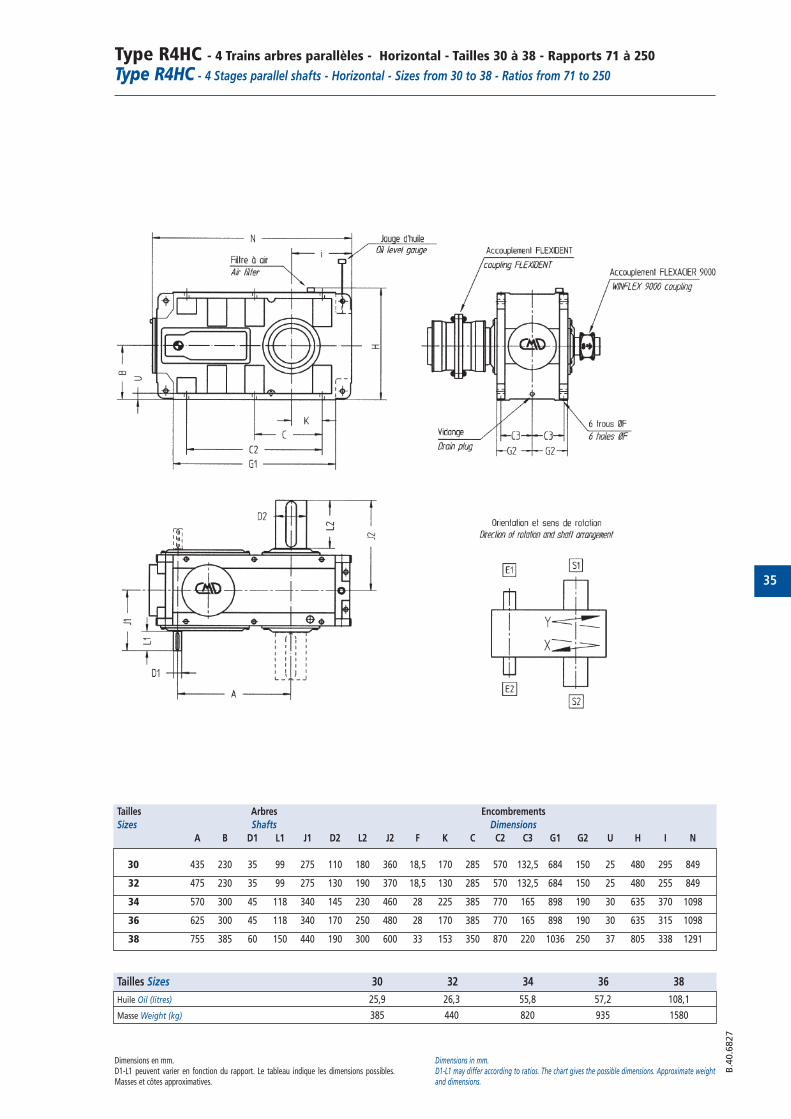
Type R4HC - 4 Trains arbres parallèles - Horizontal - Tailles 30 à 38 - Rapports 71 à 250Type R4HC - 4 Stages parallel shafts - Horizontal - Sizes from 30 to 38 - Ratios from 71 to 250
Dimensions en mm.D1-L1 peuvent varier en fonction du rapport. Le tableau indique les dimensions possibles.Masses et côtes approximatives.
Dimensions in mm.D1-L1 may differ according to ratios. The chart gives the possible dimensions. Approximate weightand dimensions.
Tailles Arbres Encombrements
Sizes Shafts Dimensions
A B D1 L1 J1 D2 L2 J2 F K C C2 C3 G1 G2 U H I N
30 435 230 35 99 275 110 180 360 18,5 170 285 570 132,5 684 150 25 480 295 849
32 475 230 35 99 275 130 190 370 18,5 130 285 570 132,5 684 150 25 480 255 849
34 570 300 45 118 340 145 230 460 28 225 385 770 165 898 190 30 635 370 1098
36 625 300 45 118 340 170 250 480 28 170 385 770 165 898 190 30 635 315 1098
38 755 385 60 150 440 190 300 600 33 153 350 870 220 1036 250 37 805 338 1291
Tailles Sizes 30 32 34 36 38
Huile Oil (litres) 25,9 26,3 55,8 57,2 108,1
Masse Weight (kg) 385 440 820 935 1580
B.4
0.6
827
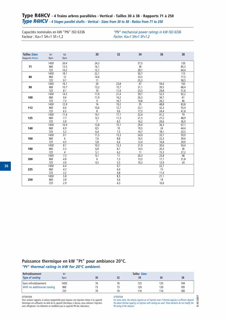
36
Type R4HCV - 4 Trains arbres parallèles - Vertical - Tailles 30 à 38 - Rapports 71 à 250Type R4HCV - 4 Stages parallel shafts - Vertical - Sizes from 30 to 38 - Ratios from 71 to 250
Capacités nominales en kW “PN” ISO 6336 Facteur : Ka=1 SH=1 SF>1,2
Puissance thermique en kW "Pt" pour ambiance 20°C."Pt" thermal rating in kW for 20°C ambient.
“PN” mechanical power ratings in kW ISO 6336 Factor: Ka=1 SH=1 SF>1.2
ATTENTIONPour certains rapports, la vitesse tangentielle peut imposer une injection même si la capacitéthermique est suffisante. Au delà de la capacité thermique ci-dessus, nous utilisons l'injectionavec réfrigérant. Ces éléments ne modifient pas la capacité PN des réducteurs.
ATTENTIONFor some ratios, the velocity requires an oil injection even if thermal capacity is sufficient. Beyondthe above thermal capacity, oil injection with cooling are used. These elements do not modify thePN rating of the reducers. B
.40.6
807
Tailles Sizes N1 N2 30 32 34 36 38Rapports Ratios Rpm Rpm
1450 20.4 24,3 57,5 12071 960 13.5 16,1 38 85,3
725 10.2 12,1 28,7 64,41450 18.1 22,1 50,7 113
80 960 12 14,6 33,5 77,5725 9.1 11 25,3 58,5
1450 16.1 20 23,8 47 59,6 10390 960 10.7 13,2 15,7 31,1 39,5 68,4
725 8.1 10 11,9 23,5 29,8 51,61450 14.5 17,9 21,4 39,7 52,5 92,2
100 960 9.6 11,9 14,2 26,3 34,7 61725 7.3 9 10,7 19,8 26,2 461450 12.9 16 19,2 35 48,8 83,8
112 960 8.6 10,6 12,7 23,1 32,3 55,4725 6.5 8 9,6 17,5 24,4 41,81450 11.6 14,1 17,1 32,4 41,2 74
125 960 7.7 9,3 11,3 21,5 27,2 48,9725 5.8 7 8,5 16,2 20,6 36,91450 10.4 12,8 15,1 29,4 36,3 67,1
140 960 6.9 8,5 10 19,5 24 44,4725 5.2 6,4 7,5 14,7 18,1 33,51450 9.1 11,5 13,3 24,9 33,7 59,9
160 960 6 7,6 8,8 16,5 22,3 39,6725 4.5 5,8 6,6 12,4 16,8 29,91450 8.1 10,3 12,3 21,9 30,6 54,4
180 960 5.3 6,8 8,1 14,5 20,3 36725 4 5,1 6,2 11 15,3 27,21450 7.3 9,1 11 20,3 25,8 48
200 960 4.8 6 7,3 13,5 17,1 31,8725 3.6 4,5 5,5 10,2 12,9 241450 6.4 9,7 22,7
225 960 4.3 6,4 15725 3.2 4,8 11,41450 5.8 8,5 21,1
250 960 3.8 5,6 14725 2.9 4,3 10,6
Refroidissement N1 Tailles Sizes
Type of cooling Rpm 30 32 34 36 38
Sans refroidissement 1450 76 76 125 125 194
With no additionnal cooling 960 73 73 120 120 185
725 70 70 116 116 180
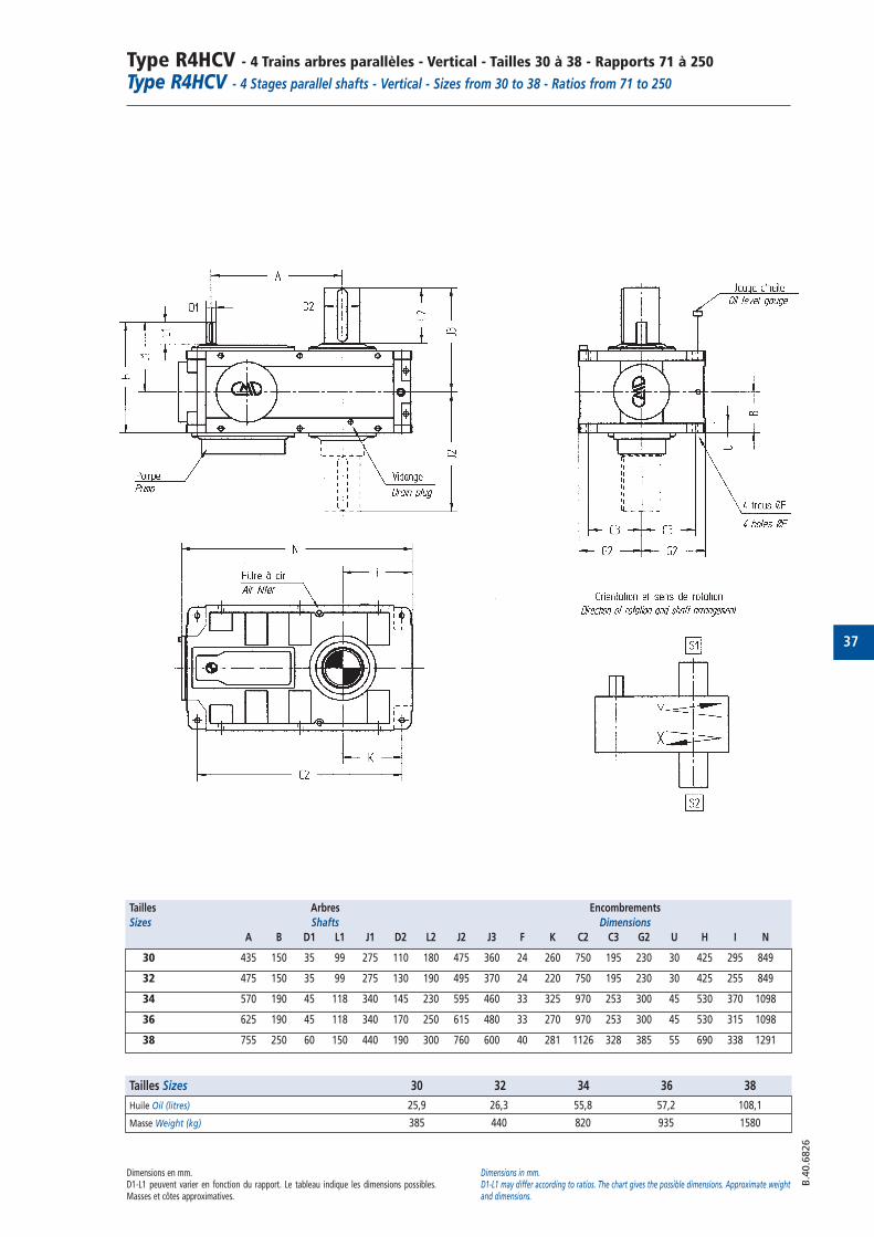
37
Type R4HCV - 4 Trains arbres parallèles - Vertical - Tailles 30 à 38 - Rapports 71 à 250Type R4HCV - 4 Stages parallel shafts - Vertical - Sizes from 30 to 38 - Ratios from 71 to 250
Dimensions en mm.D1-L1 peuvent varier en fonction du rapport. Le tableau indique les dimensions possibles.Masses et côtes approximatives.
Dimensions in mm.D1-L1 may differ according to ratios. The chart gives the possible dimensions. Approximate weightand dimensions.
B.4
0.6
826
Tailles Arbres Encombrements
Sizes Shafts Dimensions
A B D1 L1 J1 D2 L2 J2 J3 F K C2 C3 G2 U H I N
30 435 150 35 99 275 110 180 475 360 24 260 750 195 230 30 425 295 849
32 475 150 35 99 275 130 190 495 370 24 220 750 195 230 30 425 255 849
34 570 190 45 118 340 145 230 595 460 33 325 970 253 300 45 530 370 1098
36 625 190 45 118 340 170 250 615 480 33 270 970 253 300 45 530 315 1098
38 755 250 60 150 440 190 300 760 600 40 281 1126 328 385 55 690 338 1291
Tailles Sizes 30 32 34 36 38
Huile Oil (litres) 25,9 26,3 55,8 57,2 108,1
Masse Weight (kg) 385 440 820 935 1580
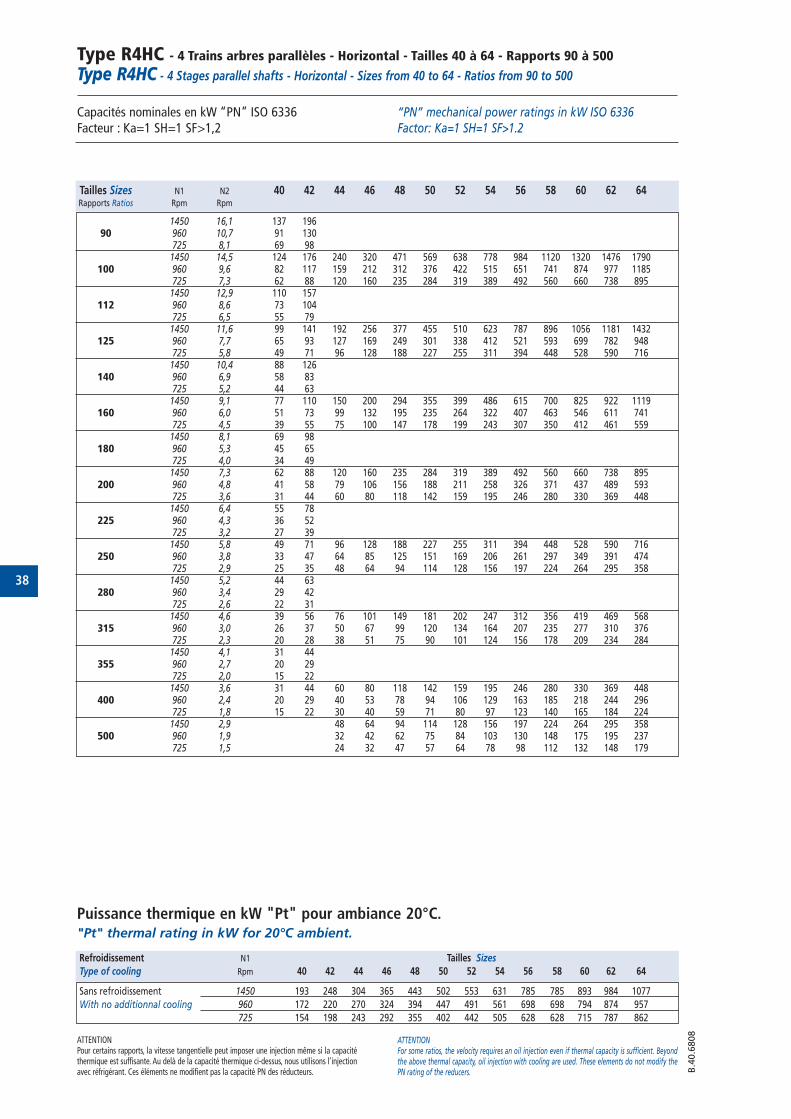
38
Type R4HC - 4 Trains arbres parallèles - Horizontal - Tailles 40 à 64 - Rapports 90 à 500Type R4HC - 4 Stages parallel shafts - Horizontal - Sizes from 40 to 64 - Ratios from 90 to 500
Capacités nominales en kW “PN” ISO 6336 Facteur : Ka=1 SH=1 SF>1,2
Puissance thermique en kW "Pt" pour ambiance 20°C."Pt" thermal rating in kW for 20°C ambient.
“PN” mechanical power ratings in kW ISO 6336 Factor: Ka=1 SH=1 SF>1.2
ATTENTIONPour certains rapports, la vitesse tangentielle peut imposer une injection même si la capacitéthermique est suffisante. Au delà de la capacité thermique ci-dessus, nous utilisons l'injectionavec réfrigérant. Ces éléments ne modifient pas la capacité PN des réducteurs.
ATTENTIONFor some ratios, the velocity requires an oil injection even if thermal capacity is sufficient. Beyondthe above thermal capacity, oil injection with cooling are used. These elements do not modify thePN rating of the reducers. B
.40.6
808
Tailles Sizes N1 N2 40 42 44 46 48 50 52 54 56 58 60 62 64Rapports Ratios Rpm Rpm
1450 16,1 137 19690 960 10,7 91 130
725 8,1 69 981450 14,5 124 176 240 320 471 569 638 778 984 1120 1320 1476 1790
100 960 9,6 82 117 159 212 312 376 422 515 651 741 874 977 1185725 7,3 62 88 120 160 235 284 319 389 492 560 660 738 8951450 12,9 110 157
112 960 8,6 73 104725 6,5 55 791450 11,6 99 141 192 256 377 455 510 623 787 896 1056 1181 1432
125 960 7,7 65 93 127 169 249 301 338 412 521 593 699 782 948725 5,8 49 71 96 128 188 227 255 311 394 448 528 590 7161450 10,4 88 126
140 960 6,9 58 83725 5,2 44 631450 9,1 77 110 150 200 294 355 399 486 615 700 825 922 1119
160 960 6,0 51 73 99 132 195 235 264 322 407 463 546 611 741725 4,5 39 55 75 100 147 178 199 243 307 350 412 461 5591450 8,1 69 98
180 960 5,3 45 65725 4,0 34 491450 7,3 62 88 120 160 235 284 319 389 492 560 660 738 895
200 960 4,8 41 58 79 106 156 188 211 258 326 371 437 489 593725 3,6 31 44 60 80 118 142 159 195 246 280 330 369 4481450 6,4 55 78
225 960 4,3 36 52725 3,2 27 391450 5,8 49 71 96 128 188 227 255 311 394 448 528 590 716
250 960 3,8 33 47 64 85 125 151 169 206 261 297 349 391 474725 2,9 25 35 48 64 94 114 128 156 197 224 264 295 3581450 5,2 44 63
280 960 3,4 29 42725 2,6 22 311450 4,6 39 56 76 101 149 181 202 247 312 356 419 469 568
315 960 3,0 26 37 50 67 99 120 134 164 207 235 277 310 376725 2,3 20 28 38 51 75 90 101 124 156 178 209 234 2841450 4,1 31 44
355 960 2,7 20 29725 2,0 15 221450 3,6 31 44 60 80 118 142 159 195 246 280 330 369 448
400 960 2,4 20 29 40 53 78 94 106 129 163 185 218 244 296725 1,8 15 22 30 40 59 71 80 97 123 140 165 184 2241450 2,9 48 64 94 114 128 156 197 224 264 295 358
500 960 1,9 32 42 62 75 84 103 130 148 175 195 237725 1,5 24 32 47 57 64 78 98 112 132 148 179
Refroidissement N1 Tailles Sizes
Type of cooling Rpm 40 42 44 46 48 50 52 54 56 58 60 62 64
Sans refroidissement 1450 193 248 304 365 443 502 553 631 785 785 893 984 1077
With no additionnal cooling 960 172 220 270 324 394 447 491 561 698 698 794 874 957
725 154 198 243 292 355 402 442 505 628 628 715 787 862
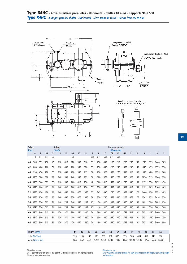
39
Type R4HC - 4 Trains arbres parallèles - Horizontal - Tailles 40 à 64 - Rapports 90 à 500Type R4HC - 4 Stages parallel shafts - Horizontal - Sizes from 40 to 64 - Ratios from 90 to 500
Dimensions en mm.D1-L1 peuvent varier en fonction du rapport. Le tableau indique les dimensions possibles.Masses et côtes approximatives.
Dimensions in mm.D1-L1 may differ according to ratios. The chart gives the possible dimensions. Approximate weightand dimensions.
B.4
0.6
825
Tailles Arbres Encombrements
Sizes Shafts Dimensions
A B B1 D1 L1 J1 D2 L2 J2 F K C C2 C3 G1 G2 U H I N S
H7 h11 h11 n6 p6 H15 Js13 Js13 Js13 Js13
40 785 355 230 45 110 410 180 300 610 33 230 435 1120 215 1260 260 40 755 395 1440 305
42 880 400 260 50 110 440 200 350 690 33 250 480 1220 250 1365 290 40 840 435 1575 330
44 990 450 290 55 110 465 220 350 715 36 270 520 1375 270 1515 315 50 935 480 1755 360
46 1105 500 320 60 140 505 240 350 725 36 300 575 1550 275 1690 325 55 1030 515 1940 390
48 1205 560 375 55 110 580 260 410 950 48 300 610 1575 330 1770 396 63 1122 570 2032 430
50 1275 600 405 60 140 630 260 410 970 52 330 660 1685 345 1887 415 63 1192 605 2166 465
52 1330 630 430 60 140 660 300 470 1060 52 345 690 1750 370 1965 440 70 1460 630 2255 485
54 1430 670 455 65 140 690 320 470 1090 56 370 740 1875 400 2106 475 70 1541 675 2416 520
56 1550 750 505 70 140 745 340 550 1225 62 450 820 2085 450 2340 530 84 1691 790 2685 620
58 1590 750 505 70 140 745 360 550 1225 62 410 820 2085 450 2340 530 84 1691 750 2685 580
60 1800 900 615 80 170 870 380 550 1320 74 590 980 2490 530 2792 625 105 2031 1130 3460 790
62 1840 900 615 80 170 870 400 650 1420 74 550 980 2490 530 2792 625 105 2031 1090 3460 750
64 1900 900 615 80 170 870 420 650 1420 74 490 980 2490 530 2792 625 105 2031 1030 3460 690
Tailles Sizes 40 42 44 46 48 50 52 54 56 58 60 62 64
Huile Oil (litres) 125 135 142 188 208 250 289 355 505 494 860 845 832
Masse Weight (kg) 2000 2625 3375 4350 5350 6380 7400 8850 10600 12100 14750 16600 18500
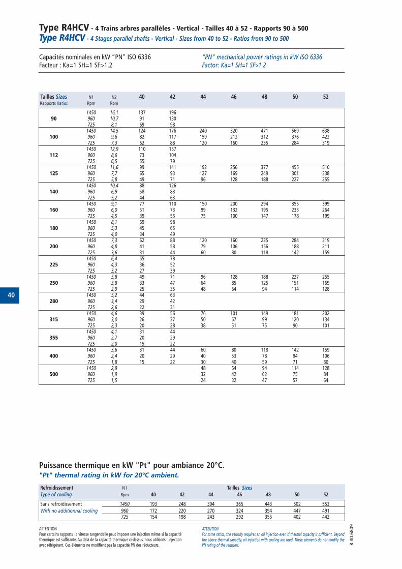
40
Type R4HCV - 4 Trains arbres parallèles - Vertical - Tailles 40 à 52 - Rapports 90 à 500
Type R4HCV - 4 Stages parallel shafts - Vertical - Sizes from 40 to 52 - Ratios from 90 to 500
Capacités nominales en kW “PN” ISO 6336 Facteur : Ka=1 SH=1 SF>1,2
Puissance thermique en kW "Pt" pour ambiance 20°C."Pt" thermal rating in kW for 20°C ambient.
“PN” mechanical power ratings in kW ISO 6336 Factor: Ka=1 SH=1 SF>1.2
ATTENTIONPour certains rapports, la vitesse tangentielle peut imposer une injection même si la capacitéthermique est suffisante. Au delà de la capacité thermique ci-dessus, nous utilisons l'injectionavec réfrigérant. Ces éléments ne modifient pas la capacité PN des réducteurs.
ATTENTIONFor some ratios, the velocity requires an oil injection even if thermal capacity is sufficient. Beyondthe above thermal capacity, oil injection with cooling are used. These elements do not modify thePN rating of the reducers. B
.40.6
809
Tailles Sizes N1 N2 40 42 44 46 48 50 52Rapports Ratios Rpm Rpm
1450 16,1 137 19690 960 10,7 91 130
725 8,1 69 981450 14,5 124 176 240 320 471 569 638
100 960 9,6 82 117 159 212 312 376 422725 7,3 62 88 120 160 235 284 3191450 12,9 110 157
112 960 8,6 73 104725 6,5 55 791450 11,6 99 141 192 256 377 455 510
125 960 7,7 65 93 127 169 249 301 338725 5,8 49 71 96 128 188 227 2551450 10,4 88 126
140 960 6,9 58 83725 5,2 44 631450 9,1 77 110 150 200 294 355 399
160 960 6,0 51 73 99 132 195 235 264725 4,5 39 55 75 100 147 178 1991450 8,1 69 98
180 960 5,3 45 65725 4,0 34 491450 7,3 62 88 120 160 235 284 319
200 960 4,8 41 58 79 106 156 188 211725 3,6 31 44 60 80 118 142 1591450 6,4 55 78
225 960 4,3 36 52725 3,2 27 391450 5,8 49 71 96 128 188 227 255
250 960 3,8 33 47 64 85 125 151 169725 2,9 25 35 48 64 94 114 1281450 5,2 44 63
280 960 3,4 29 42725 2,6 22 311450 4,6 39 56 76 101 149 181 202
315 960 3,0 26 37 50 67 99 120 134725 2,3 20 28 38 51 75 90 1011450 4,1 31 44
355 960 2,7 20 29725 2,0 15 221450 3,6 31 44 60 80 118 142 159
400 960 2,4 20 29 40 53 78 94 106725 1,8 15 22 30 40 59 71 801450 2,9 48 64 94 114 128
500 960 1,9 32 42 62 75 84725 1,5 24 32 47 57 64
Refroidissement N1 Tailles Sizes
Type of cooling Rpm 40 42 44 46 48 50 52
Sans refroidissement 1450 193 248 304 365 443 502 553
With no additionnal cooling 960 172 220 270 324 394 447 491725 154 198 243 292 355 402 442
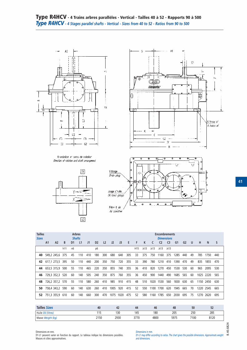
41
Type R4HCV - 4 Trains arbres parallèles - Vertical - Tailles 40 à 52 - Rapports 90 à 500
Type R4HCV - 4 Stages parallel shafts - Vertical - Sizes from 40 to 52 - Ratios from 90 to 500
Dimensions en mm.D1-L1 peuvent varier en fonction du rapport. Le tableau indique les dimensions possibles.Masses et côtes approximatives.
Dimensions in mm.D1-L1 may differ according to ratios. The chart gives the possible dimensions. Approximate weightand dimensions.
B.4
0.6
824
Tailles Arbres Encombrements
Sizes Shafts Dimensions
A1 A2 B D1 L1 J1 D2 L2 J2 J3 E F K C C2 C3 G1 G2 U H N S
h11 n6 p6 H15 Js13 Js13 Js13 Js13
40 549,2 245,6 375 45 110 410 180 300 680 640 305 33 375 750 1160 375 1285 440 49 785 1750 440
42 617,1 273,5 395 50 110 440 200 350 750 720 355 33 390 780 1210 410 1390 470 49 835 1855 470
44 653,5 315,9 500 55 110 465 220 350 855 740 355 36 410 820 1270 450 1530 530 60 965 2095 530
46 729,3 352,3 520 60 140 505 240 350 875 760 355 36 450 900 1440 490 1685 565 60 1025 2220 565
48 726,2 357,2 570 55 110 580 260 410 985 910 415 48 510 1020 1530 560 1830 630 65 1150 2450 630
50 758,4 343,2 590 60 140 630 260 410 1005 920 415 52 550 1100 1700 620 1945 665 70 1220 2545 665
52 751,3 355,9 610 60 140 660 300 470 1075 1020 475 52 580 1160 1785 650 2030 695 75 1270 2620 695
Tailles Sizes 40 42 44 46 48 50 52
Huile Oil (litres) 115 130 145 180 205 250 285
Masse Weight (kg) 2150 2930 3770 4800 5975 7100 8120
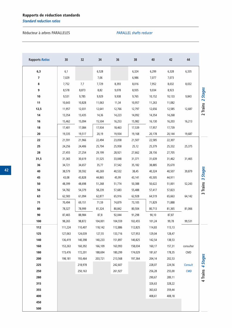
42
Rapports de réduction standards
Standard reduction ratios
Réducteur à arbres PARALLELES PARALLEL shafts reducer
Rapports Ratios 30 32 34 36 38 40 42 44
6,3 6,1 6,528 6,324 6,299 6,328 6,335
7 7,029 7,06 6,986 7,077 7,073
8 7,752 7,7 7,729 8,393 8,016 7,952 8,032 8,032
9 8,578 8,873 8,82 9,078 8,935 9,034 8,923
10 9,531 9,785 9,929 9,938 9,765 10,152 10,133 9,843
11 10,643 10,828 11,063 11,34 10,957 11,263 11,082
12,5 11,957 12,031 12,641 12,766 12,797 12,656 12,585 12,687
14 13,354 13,435 14,36 14,223 14,092 14,354 14,268
16 15,462 15,094 15,504 16,253 15,982 16,130 16,203 16,213
18 17,401 17,084 17,934 18,463 17,539 17,957 17,739
20 19,335 19,517 20,19 19,934 19,168 20,178 20,144 19,687
22 21,591 21,966 22,494 23,058 21,507 22,585 22,307
25 24,256 24,406 25,704 25,958 25,12 25,379 25,332 25,375
28 27,455 27,254 29,199 28,921 27,662 28,156 27,705
31,5 31,365 30,619 31,525 33,048 31,371 31,639 31,462 31,465
36 34,721 34,657 35,77 37,542 35,182 38,885 35,670
40 38,579 39,592 40,269 40,532 38,45 40,324 40,507 39,879
45 43,08 43,828 44,865 45,99 43,141 45,505 44,911
50 48,399 48,698 51,268 51,774 50,388 50,622 51,001 52,243
56 54,782 54,379 58,239 57,683 55,488 57,417 57,823
63 62,583 61,094 62,877 65,916 62,928 64,519 65,663 64,142
71 70,494 69,151 71,59 74,879 73,105 71,829 71,888
80 78,327 78,999 81,324 80,842 80,504 80,713 81,365 81,066
90 87,465 88,984 87,8 92,044 91,298 90,10 87,87
100 98,265 98,872 104,001 104,559 102,455 101,24 99,78 99,531
112 111,224 110,407 118,142 112,886 112,825 114,83 113,13
125 127,063 124,039 127,55 133,716 127,953 129,04 128,47
140 136,419 140,398 140,233 151,897 140,825 142,54 138,53
160 153,263 160,392 166,109 163,993 158,034 160,17 157,31 consulter
180 173,476 172,201 188,694 180,299 174,029 181,67 178,35 CMD
200 198,181 193,464 203,721 213,568 197,364 204,14 202,53
225 218,978 242,607 228,07 224,56 Consult
250 250,163 261,927 256,28 255,00 CMD
280 290,67 289,11
315 326,63 328,22
355 363,63 359,44
400 408,61 408,18
450
500
4 Tr
ains
4 S
tage
s3
Trai
ns 3
Sta
ges
2 Tr
ains
2 S
tage
s
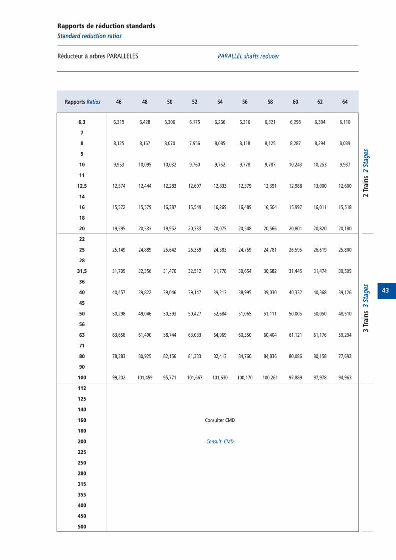
43
Rapports de réduction standards
Standard reduction ratios
Réducteur à arbres PARALLELES PARALLEL shafts reducer
Rapports Ratios 46 48 50 52 54 56 58 60 62 64
6,3 6,319 6,428 6,306 6,175 6,266 6,316 6,321 6,298 6,304 6,110
7
8 8,125 8,167 8,070 7,956 8,085 8,118 8,125 8,287 8,294 8,039
9
10 9,953 10,095 10,032 9,760 9,752 9,778 9,787 10,243 10,253 9,937
11
12,5 12,574 12,444 12,283 12,607 12,833 12,379 12,391 12,988 13,000 12,600
14
16 15,572 15,579 16,387 15,549 16,269 16,489 16,504 15,997 16,011 15,518
18
20 19,595 20,533 19,952 20,333 20,075 20,548 20,566 20,801 20,820 20,180
22
25 25,149 24,889 25,642 26,359 24,383 24,759 24,781 26,595 26,619 25,800
28
31,5 31,709 32,356 31,470 32,512 31,778 30,654 30,682 31,445 31,474 30,505
36
40 40,457 39,822 39,046 39,147 39,213 38,995 39,030 40,332 40,368 39,126
45
50 50,298 49,046 50,393 50,427 52,684 51,065 51,111 50,005 50,050 48,510
56
63 63,658 61,490 58,744 63,033 64,969 60,350 60,404 61,121 61,176 59,294
71
80 78,383 80,925 82,156 81,333 82,413 84,760 84,836 80,086 80,158 77,692
90
100 99,202 101,459 95,771 101,667 101,630 100,170 100,261 97,889 97,978 94,963
112
125
140
160 Consulter CMD
180
200 Consult CMD
225
250
280
315
355
400
450
500
3 Tr
ains
3 S
tage
s2
Trai
ns 2
Sta
ges

44
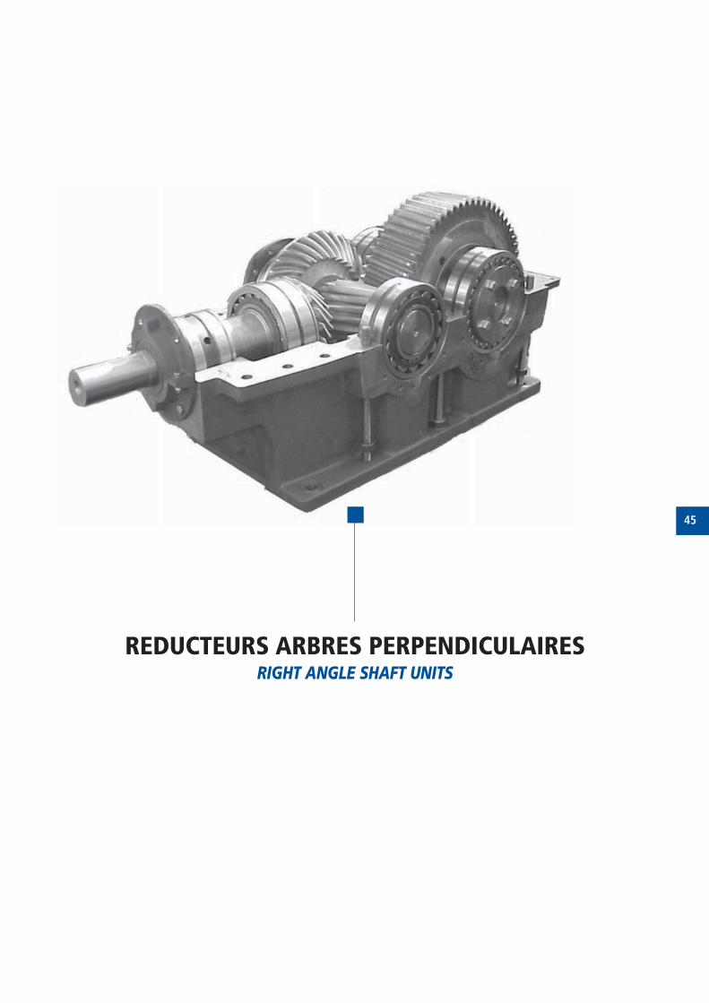
45
REDUCTEURS ARBRES PERPENDICULAIRESRIGHT ANGLE SHAFT UNITS
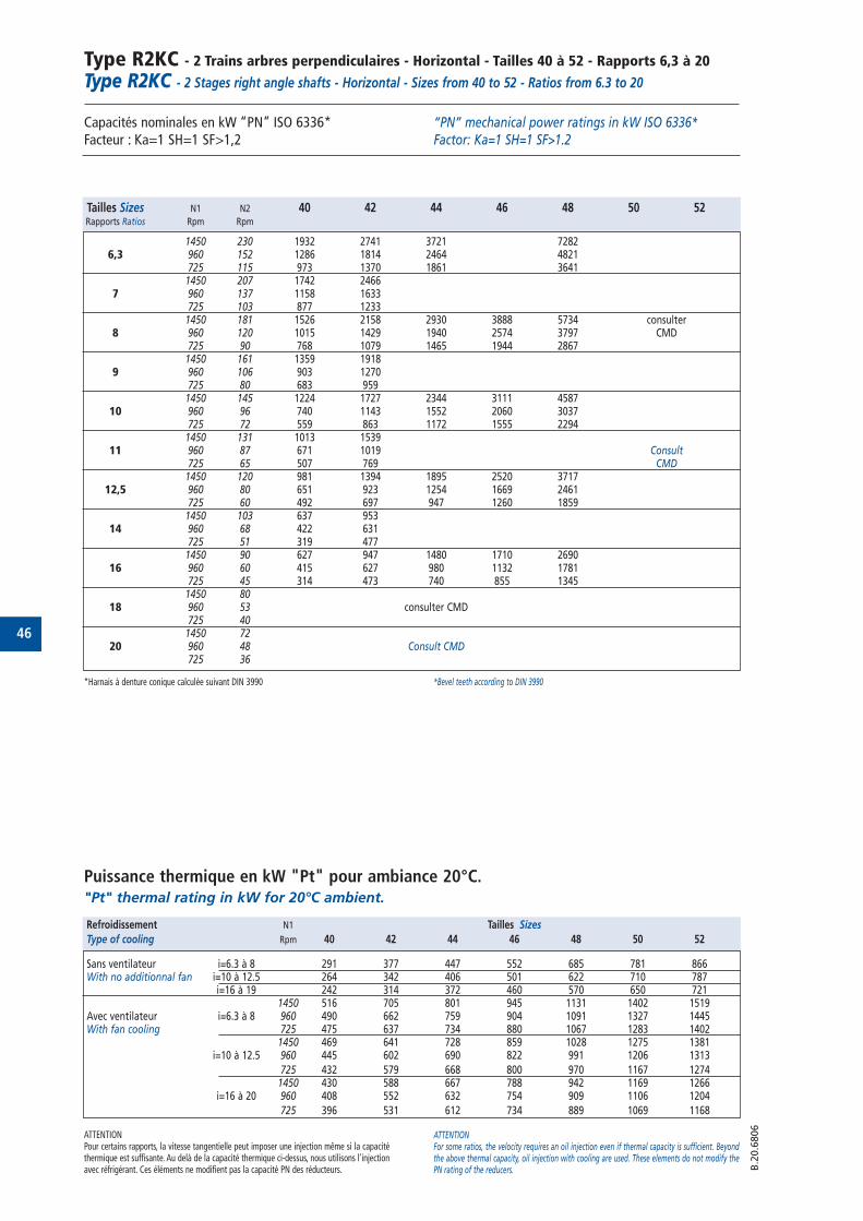
46
Type R2KC - 2 Trains arbres perpendiculaires - Horizontal - Tailles 40 à 52 - Rapports 6,3 à 20Type R2KC - 2 Stages right angle shafts - Horizontal - Sizes from 40 to 52 - Ratios from 6.3 to 20
Capacités nominales en kW “PN” ISO 6336* Facteur : Ka=1 SH=1 SF>1,2
Puissance thermique en kW "Pt" pour ambiance 20°C."Pt" thermal rating in kW for 20°C ambient.
“PN” mechanical power ratings in kW ISO 6336* Factor: Ka=1 SH=1 SF>1.2
ATTENTIONPour certains rapports, la vitesse tangentielle peut imposer une injection même si la capacitéthermique est suffisante. Au delà de la capacité thermique ci-dessus, nous utilisons l'injectionavec réfrigérant. Ces éléments ne modifient pas la capacité PN des réducteurs.
ATTENTIONFor some ratios, the velocity requires an oil injection even if thermal capacity is sufficient. Beyondthe above thermal capacity, oil injection with cooling are used. These elements do not modify thePN rating of the reducers. B
.20.6
806
Tailles Sizes N1 N2 40 42 44 46 48 50 52Rapports Ratios Rpm Rpm
1450 230 1932 2741 3721 72826,3 960 152 1286 1814 2464 4821
725 115 973 1370 1861 36411450 207 1742 2466
7 960 137 1158 1633725 103 877 12331450 181 1526 2158 2930 3888 5734 consulter
8 960 120 1015 1429 1940 2574 3797 CMD725 90 768 1079 1465 1944 28671450 161 1359 1918
9 960 106 903 1270725 80 683 9591450 145 1224 1727 2344 3111 4587
10 960 96 740 1143 1552 2060 3037725 72 559 863 1172 1555 22941450 131 1013 1539
11 960 87 671 1019 Consult725 65 507 769 CMD1450 120 981 1394 1895 2520 3717
12,5 960 80 651 923 1254 1669 2461725 60 492 697 947 1260 18591450 103 637 953
14 960 68 422 631725 51 319 4771450 90 627 947 1480 1710 2690
16 960 60 415 627 980 1132 1781725 45 314 473 740 855 13451450 80
18 960 53 consulter CMD725 401450 72
20 960 48 Consult CMD725 36
Refroidissement N1 Tailles Sizes
Type of cooling Rpm 40 42 44 46 48 50 52
Sans ventilateur i=6.3 à 8 291 377 447 552 685 781 866With no additionnal fan i=10 à 12.5 264 342 406 501 622 710 787
i=16 à 19 242 314 372 460 570 650 7211450 516 705 801 945 1131 1402 1519
Avec ventilateur i=6.3 à 8 960 490 662 759 904 1091 1327 1445With fan cooling 725 475 637 734 880 1067 1283 1402
1450 469 641 728 859 1028 1275 1381i=10 à 12.5 960 445 602 690 822 991 1206 1313
725 432 579 668 800 970 1167 12741450 430 588 667 788 942 1169 1266
i=16 à 20 960 408 552 632 754 909 1106 1204
725 396 531 612 734 889 1069 1168
*Harnais à denture conique calculée suivant DIN 3990 *Bevel teeth according to DIN 3990
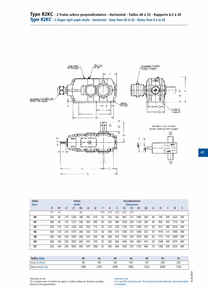
47
Type R2KC - 2 Trains arbres perpendiculaires - Horizontal - Tailles 40 à 52 - Rapports 6,3 à 20Type R2KC - 2 Stages right angle shafts - Horizontal - Sizes from 40 to 52 - Ratios from 6.3 to 20
B.2
0.6
831
Tailles Arbres Encombrements
Sizes Shafts Dimensions
B D1 L1 J1 D2 L2 J2 F K C C2 C3 G1 G2 U H I N S
h11 n6 p6 H15 Js13 Js13 Js13 Js13
40 355 90 170 1230 180 300 610 33 230 435 940 215 1080 260 40 740 395 1625 305
42 400 90 170 1275 200 350 690 33 250 480 1020 250 1165 290 40 820 435 1710 330
44 450 110 210 1530 220 350 715 36 270 520 1150 270 1290 315 50 915 480 2010 360
46 500 110 210 1575 240 350 725 36 300 575 1300 275 1440 325 55 1010 515 2090 390
48 560 140 250 1830 260 410 950 48 300 610 1350 330 1556 396 63 1172 570 2400 430
50 600 140 250 1870 260 410 970 52 330 660 1440 345 1667 415 63 1248 605 2475 465
52 630 140 250 1895 300 470 1060 52 345 690 1505 370 1735 440 70 1300 630 2525 485
Dimensions en mm.D1-L1 peuvent varier en fonction du rapport. Le tableau indique les dimensions possibles.Masses et côtes approximatives.
Dimensions in mm.D1-L1 may differ according to ratios. The chart gives the possible dimensions. Approximate weightand dimensions.
Tailles Sizes 40 42 44 46 48 50 52
Huile Oil (litres) 96 105 120 145 197 234 270
Masse Weight (kg) 1800 2395 3090 3965 5220 6280 7160
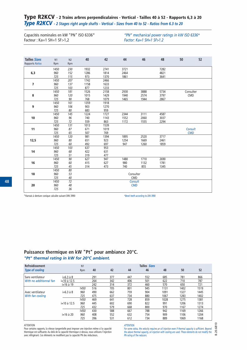
48
Type R2KCV - 2 Trains arbres perpendiculaires - Vertical - Tailles 40 à 52 - Rapports 6,3 à 20Type R2KCV - 2 Stages right angle shafts - Vertical - Sizes from 40 to 52 - Ratios from 6.3 to 20
Capacités nominales en kW “PN” ISO 6336* Facteur : Ka=1 SH=1 SF>1,2
Puissance thermique en kW "Pt" pour ambiance 20°C."Pt" thermal rating in kW for 20°C ambient.
“PN” mechanical power ratings in kW ISO 6336* Factor: Ka=1 SH=1 SF>1.2
ATTENTIONPour certains rapports, la vitesse tangentielle peut imposer une injection même si la capacitéthermique est suffisante. Au delà de la capacité thermique ci-dessus, nous utilisons l'injectionavec réfrigérant. Ces éléments ne modifient pas la capacité PN des réducteurs.
ATTENTIONFor some ratios, the velocity requires an oil injection even if thermal capacity is sufficient. Beyondthe above thermal capacity, oil injection with cooling are used. These elements do not modify thePN rating of the reducers. B
.20.6
810
Tailles Sizes N1 N2 40 42 44 46 48 50 52Rapports Ratios Rpm Rpm
1450 230 1932 2741 3721 72826,3 960 152 1286 1814 2464 4821
725 115 973 1370 1861 36411450 207 1742 2466
7 960 137 1158 1633725 103 877 12331450 181 1526 2158 2930 3888 5734 Consulter
8 960 120 1015 1429 1940 2574 3797 CMD725 90 768 1079 1465 1944 28671450 161 1359 1918
9 960 106 903 1270725 80 683 9591450 145 1224 1727 2344 3111 4587
10 960 96 740 1143 1552 2060 3037725 72 559 863 1172 1555 22941450 131 1013 1539
11 960 87 671 1019 Consult725 65 507 769 CMD1450 120 981 1394 1895 2520 3717
12,5 960 80 651 923 1254 1669 2461725 60 492 697 947 1260 18591450 103 637 953
14 960 68 422 631725 51 319 4771450 90 627 947 1480 1710 2690
16 960 60 415 627 980 1132 1781725 45 314 473 740 855 13451450 80
18 960 53 Consulter725 40 CMD
1450 72 Consult20 960 48 CMD
725 36
Refroidissement N1 Tailles Sizes
Type of cooling Rpm 40 42 44 46 48 50 52
Sans ventilateur i=6.3 à 8 291 377 447 552 685 781 866With no additionnal fan i=10 à 12.5 264 342 406 501 622 710 787
i=16 à 19 242 314 372 460 570 650 7211450 516 705 801 945 1131 1402 1519
Avec ventilateur i=6.3 à 8 960 490 662 759 904 1091 1327 1445With fan cooling 725 475 637 734 880 1067 1283 1402
1450 469 641 728 859 1028 1275 1381i=10 à 12.5 960 445 602 690 822 991 1206 1313
725 432 579 668 800 970 1167 12741450 430 588 667 788 942 1169 1266
i=16 à 20 960 408 552 632 754 909 1106 1204725 396 531 612 734 889 1069 1168
*Harnais à denture conique calculée suivant DIN 3990 *Bevel teeth according to DIN 3990
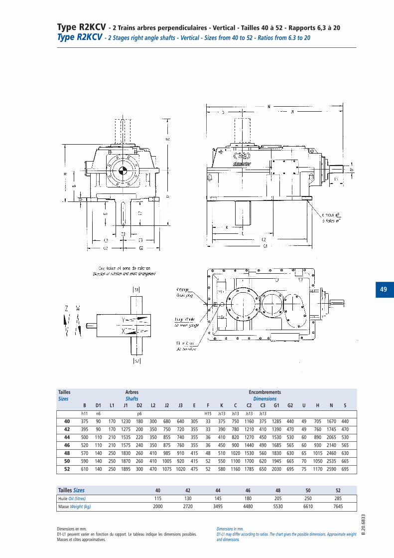
49
Type R2KCV - 2 Trains arbres perpendiculaires - Vertical - Tailles 40 à 52 - Rapports 6,3 à 20Type R2KCV - 2 Stages right angle shafts - Vertical - Sizes from 40 to 52 - Ratios from 6.3 to 20
B.2
0.6
833
Tailles Arbres Encombrements
Sizes Shafts Dimensions
B D1 L1 J1 D2 L2 J2 J3 E F K C C2 C3 G1 G2 U H N S
h11 n6 p6 H15 Js13 Js13 Js13 Js13
40 375 90 170 1230 180 300 680 640 305 33 375 750 1160 375 1285 440 49 705 1670 440
42 395 90 170 1275 200 350 750 720 355 33 390 780 1210 410 1390 470 49 760 1745 470
44 500 110 210 1535 220 350 855 740 355 36 410 820 1270 450 1530 530 60 890 2065 530
46 520 110 210 1575 240 350 875 760 355 36 450 900 1440 490 1685 565 60 930 2140 565
48 570 140 250 1830 260 410 985 910 415 48 510 1020 1530 560 1830 630 65 1015 2460 630
50 590 140 250 1870 260 410 1005 920 415 52 550 1100 1700 620 1945 665 70 1050 2535 665
52 610 140 250 1895 300 470 1075 1020 475 52 580 1160 1785 650 2030 695 75 1170 2590 695
Dimensions en mm.D1-L1 peuvent varier en fonction du rapport. Le tableau indique les dimensions possibles.Masses et côtes approximatives.
Dimensions in mm.D1-L1 may differ according to ratios. The chart gives the possible dimensions. Approximate weightand dimensions.
Tailles Sizes 40 42 44 46 48 50 52
Huile Oil (litres) 115 130 145 180 205 250 285
Masse Weight (kg) 2000 2720 3495 4480 5530 6610 7645
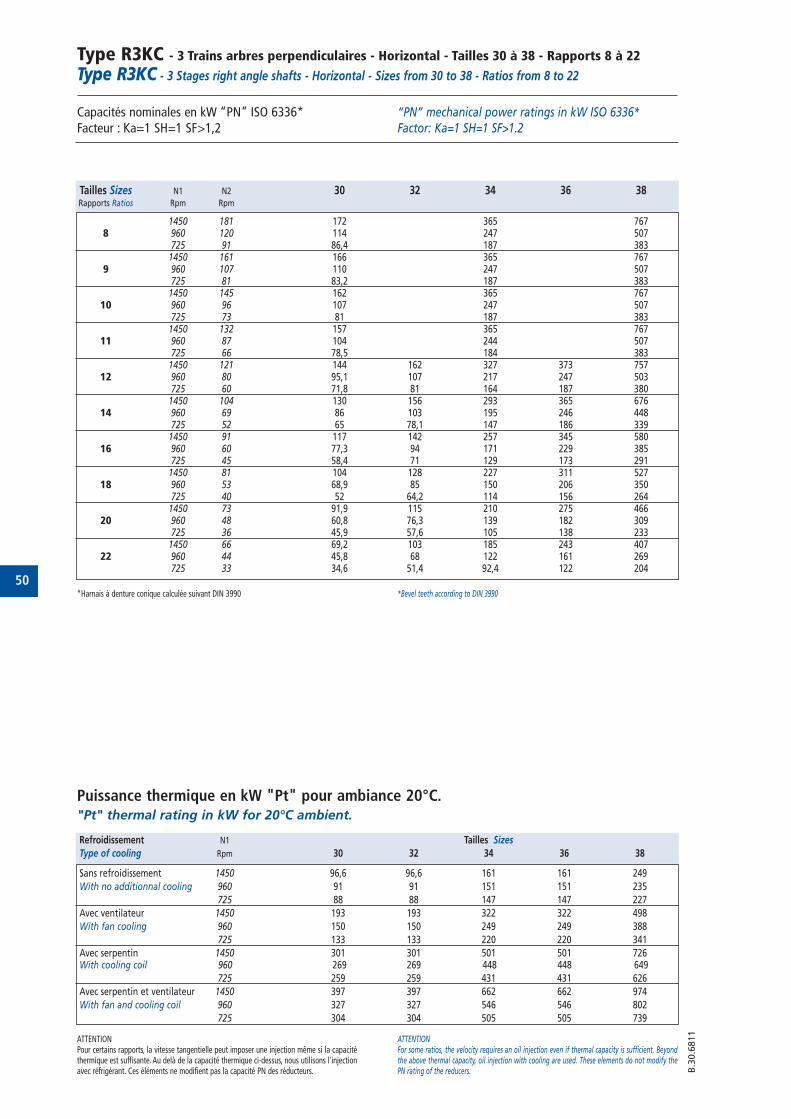
50
Type R3KC - 3 Trains arbres perpendiculaires - Horizontal - Tailles 30 à 38 - Rapports 8 à 22Type R3KC - 3 Stages right angle shafts - Horizontal - Sizes from 30 to 38 - Ratios from 8 to 22
Capacités nominales en kW “PN” ISO 6336* Facteur : Ka=1 SH=1 SF>1,2
“PN” mechanical power ratings in kW ISO 6336* Factor: Ka=1 SH=1 SF>1.2
B.3
0.6
811
Tailles Sizes N1 N2 30 32 34 36 38Rapports Ratios Rpm Rpm
1450 181 172 365 7678 960 120 114 247 507
725 91 86,4 187 3831450 161 166 365 767
9 960 107 110 247 507725 81 83,2 187 383
1450 145 162 365 76710 960 96 107 247 507
725 73 81 187 3831450 132 157 365 767
11 960 87 104 244 507725 66 78,5 184 383
1450 121 144 162 327 373 75712 960 80 95,1 107 217 247 503
725 60 71,8 81 164 187 3801450 104 130 156 293 365 676
14 960 69 86 103 195 246 448725 52 65 78,1 147 186 339
1450 91 117 142 257 345 58016 960 60 77,3 94 171 229 385
725 45 58,4 71 129 173 2911450 81 104 128 227 311 527
18 960 53 68,9 85 150 206 350725 40 52 64,2 114 156 264
1450 73 91,9 115 210 275 46620 960 48 60,8 76,3 139 182 309
725 36 45,9 57,6 105 138 2331450 66 69,2 103 185 243 407
22 960 44 45,8 68 122 161 269725 33 34,6 51,4 92,4 122 204
Puissance thermique en kW "Pt" pour ambiance 20°C."Pt" thermal rating in kW for 20°C ambient.
ATTENTIONPour certains rapports, la vitesse tangentielle peut imposer une injection même si la capacitéthermique est suffisante. Au delà de la capacité thermique ci-dessus, nous utilisons l'injectionavec réfrigérant. Ces éléments ne modifient pas la capacité PN des réducteurs.
ATTENTIONFor some ratios, the velocity requires an oil injection even if thermal capacity is sufficient. Beyondthe above thermal capacity, oil injection with cooling are used. These elements do not modify thePN rating of the reducers.
Refroidissement N1 Tailles Sizes
Type of cooling Rpm 30 32 34 36 38
Sans refroidissement 1450 96,6 96,6 161 161 249
With no additionnal cooling 960 91 91 151 151 235
725 88 88 147 147 227
Avec ventilateur 1450 193 193 322 322 498
With fan cooling 960 150 150 249 249 388
725 133 133 220 220 341
Avec serpentin 1450 301 301 501 501 726With cooling coil 960 269 269 448 448 649
725 259 259 431 431 626
Avec serpentin et ventilateur 1450 397 397 662 662 974
With fan and cooling coil 960 327 327 546 546 802
725 304 304 505 505 739
*Harnais à denture conique calculée suivant DIN 3990 *Bevel teeth according to DIN 3990

51
Type R3KC - 3 Trains arbres perpendiculaires - Horizontal - Tailles 30 à 38 - Rapports 8 à 22Type R3KC - 3 Stages right angle shafts - Horizontal - Sizes from 30 to 38 - Ratios from 8 to 22
B.3
0.6
824
Dimensions en mm.D1-L1 peuvent varier en fonction du rapport. Le tableau indique les dimensions possibles.Masses et côtes approximatives.
Dimensions in mm.D1-L1 may differ according to ratios. The chart gives the possible dimensions. Approximate weightand dimensions.
Tailles Arbres Encombrements
Sizes Shafts Dimensions
B D1 L1 J1 D2 L2 J2 F K C C2 C3 G1 G2 U H I N
30 230 38 100 720 110 180 360 18,5 170 285 570 132,5 684 150 25 480 295 1015
32 230 38 100 760 130 190 370 18,5 130 285 570 132,5 684 150 25 480 255 1015
34 300 50 140 940 145 230 460 28 225 385 770 165 898 190 30 635 370 1310
36 300 50 140 995 170 250 480 28 170 385 770 165 898 190 30 635 315 1310
38 385 75 160 1220 190 300 600 33 153 350 870 220 1036 250 37 805 338 1558
Tailles Sizes 30 32 34 36 38
Huile Oil (litres) 26,2 26,6 57 58,6 111,6
Masse Weight (kg) 395 450 840 940 1640
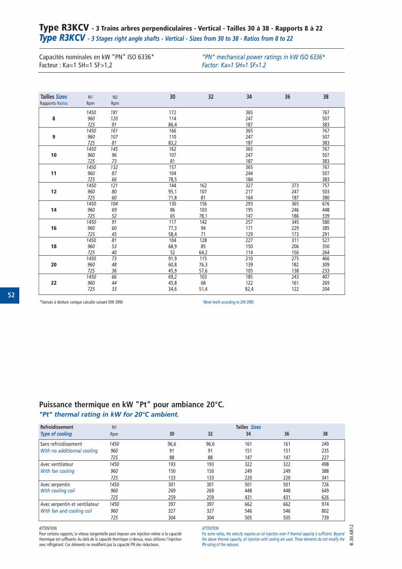
52
Type R3KCV - 3 Trains arbres perpendiculaires - Vertical - Tailles 30 à 38 - Rapports 8 à 22Type R3KCV - 3 Stages right angle shafts - Vertical - Sizes from 30 to 38 - Ratios from 8 to 22
Capacités nominales en kW “PN” ISO 6336* Facteur : Ka=1 SH=1 SF>1,2
“PN” mechanical power ratings in kW ISO 6336* Factor: Ka=1 SH=1 SF>1.2
B.3
0.6
812
Tailles Sizes N1 N2 30 32 34 36 38Rapports Ratios Rpm Rpm
1450 181 172 365 7678 960 120 114 247 507
725 91 86,4 187 3831450 161 166 365 767
9 960 107 110 247 507725 81 83,2 187 3831450 145 162 365 767
10 960 96 107 247 507725 73 81 187 3831450 132 157 365 767
11 960 87 104 244 507725 66 78,5 184 3831450 121 144 162 327 373 757
12 960 80 95,1 107 217 247 503725 60 71,8 81 164 187 3801450 104 130 156 293 365 676
14 960 69 86 103 195 246 448725 52 65 78,1 147 186 3391450 91 117 142 257 345 580
16 960 60 77,3 94 171 229 385725 45 58,4 71 129 173 2911450 81 104 128 227 311 527
18 960 53 68,9 85 150 206 350725 40 52 64,2 114 156 2641450 73 91,9 115 210 275 466
20 960 48 60,8 76,3 139 182 309725 36 45,9 57,6 105 138 2331450 66 69,2 103 185 243 407
22 960 44 45,8 68 122 161 269725 33 34,6 51,4 92,4 122 204
Puissance thermique en kW "Pt" pour ambiance 20°C."Pt" thermal rating in kW for 20°C ambient.
ATTENTIONPour certains rapports, la vitesse tangentielle peut imposer une injection même si la capacitéthermique est suffisante. Au delà de la capacité thermique ci-dessus, nous utilisons l'injectionavec réfrigérant. Ces éléments ne modifient pas la capacité PN des réducteurs.
ATTENTIONFor some ratios, the velocity requires an oil injection even if thermal capacity is sufficient. Beyondthe above thermal capacity, oil injection with cooling are used. These elements do not modify thePN rating of the reducers.
Refroidissement N1 Tailles Sizes
Type of cooling Rpm 30 32 34 36 38
Sans refroidissement 1450 96,6 96,6 161 161 249
With no additionnal cooling 960 91 91 151 151 235
725 88 88 147 147 227
Avec ventilateur 1450 193 193 322 322 498
With fan cooling 960 150 150 249 249 388
725 133 133 220 220 341
Avec serpentin 1450 301 301 501 501 726With cooling coil 960 269 269 448 448 649
725 259 259 431 431 626
Avec serpentin et ventilateur 1450 397 397 662 662 974
With fan and cooling coil 960 327 327 546 546 802
725 304 304 505 505 739
*Harnais à denture conique calculée suivant DIN 3990 *Bevel teeth according to DIN 3990
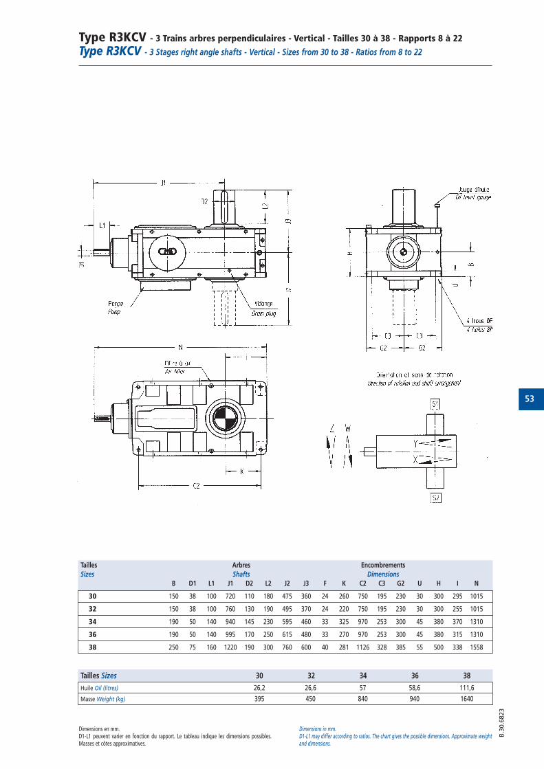
53
Type R3KCV - 3 Trains arbres perpendiculaires - Vertical - Tailles 30 à 38 - Rapports 8 à 22Type R3KCV - 3 Stages right angle shafts - Vertical - Sizes from 30 to 38 - Ratios from 8 to 22
B.3
0.6
823
Dimensions en mm.D1-L1 peuvent varier en fonction du rapport. Le tableau indique les dimensions possibles.Masses et côtes approximatives.
Dimensions in mm.D1-L1 may differ according to ratios. The chart gives the possible dimensions. Approximate weightand dimensions.
Tailles Arbres Encombrements
Sizes Shafts Dimensions
B D1 L1 J1 D2 L2 J2 J3 F K C2 C3 G2 U H I N
30 150 38 100 720 110 180 475 360 24 260 750 195 230 30 300 295 1015
32 150 38 100 760 130 190 495 370 24 220 750 195 230 30 300 255 1015
34 190 50 140 940 145 230 595 460 33 325 970 253 300 45 380 370 1310
36 190 50 140 995 170 250 615 480 33 270 970 253 300 45 380 315 1310
38 250 75 160 1220 190 300 760 600 40 281 1126 328 385 55 500 338 1558
Tailles Sizes 30 32 34 36 38
Huile Oil (litres) 26,2 26,6 57 58,6 111,6
Masse Weight (kg) 395 450 840 940 1640
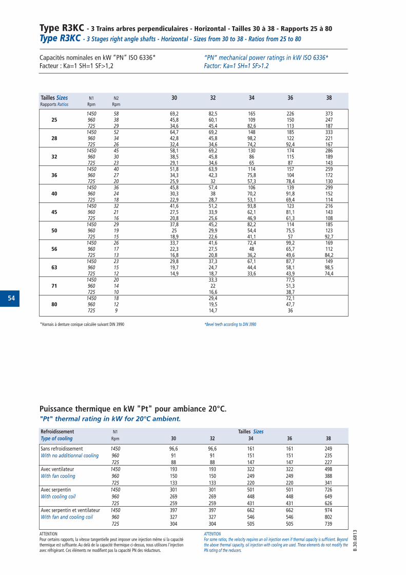
54
Type R3KC - 3 Trains arbres perpendiculaires - Horizontal - Tailles 30 à 38 - Rapports 25 à 80Type R3KC - 3 Stages right angle shafts - Horizontal - Sizes from 30 to 38 - Ratios from 25 to 80
Capacités nominales en kW “PN” ISO 6336* Facteur : Ka=1 SH=1 SF>1,2
“PN” mechanical power ratings in kW ISO 6336* Factor: Ka=1 SH=1 SF>1.2
B.3
0.6
813
Tailles Sizes N1 N2 30 32 34 36 38Rapports Ratios Rpm Rpm
1450 58 69,2 82,5 165 226 37325 960 38 45,8 60,1 109 150 247
725 29 34,6 45,4 82,6 113 1871450 52 64,7 69,2 148 185 333
28 960 34 42,8 45,8 98,2 122 221725 26 32,4 34,6 74,2 92,4 167
1450 45 58,1 69,2 130 174 28632 960 30 38,5 45,8 86 115 189
725 23 29,1 34,6 65 87 1431450 40 51,8 63,9 114 157 259
36 960 27 34,3 42,3 75,8 104 172725 20 25,9 32 57,3 78,4 130
1450 36 45,8 57,4 106 139 29940 960 24 30,3 38 70,2 91,8 152
725 18 22,9 28,7 53,1 69,4 1141450 32 41,6 51,2 93,8 123 216
45 960 21 27,5 33,9 62,1 81,1 143725 16 20,8 25,6 46,9 61,3 108
1450 29 37,8 45,2 82,2 114 18550 960 19 25 29,9 54,4 75,5 123
725 15 18,9 22,6 41,1 57 92,71450 26 33,7 41,6 72,4 99,2 169
56 960 17 22,3 27,5 48 65,7 112725 13 16,8 20,8 36,2 49,6 84,2
1450 23 29,8 37,3 67,1 87,7 14963 960 15 19,7 24,7 44,4 58,1 98,5
725 12 14,9 18,7 33,6 43,9 74,41450 20 33,3 77,5
71 960 14 22 51,3725 10 16,6 38,71450 18 29,4 72,1
80 960 12 19,5 47,7725 9 14,7 36
Puissance thermique en kW "Pt" pour ambiance 20°C."Pt" thermal rating in kW for 20°C ambient.
ATTENTIONPour certains rapports, la vitesse tangentielle peut imposer une injection même si la capacitéthermique est suffisante. Au delà de la capacité thermique ci-dessus, nous utilisons l'injectionavec réfrigérant. Ces éléments ne modifient pas la capacité PN des réducteurs.
ATTENTIONFor some ratios, the velocity requires an oil injection even if thermal capacity is sufficient. Beyondthe above thermal capacity, oil injection with cooling are used. These elements do not modify thePN rating of the reducers.
Refroidissement N1 Tailles Sizes
Type of cooling Rpm 30 32 34 36 38
Sans refroidissement 1450 96,6 96,6 161 161 249
With no additionnal cooling 960 91 91 151 151 235
725 88 88 147 147 227
Avec ventilateur 1450 193 193 322 322 498
With fan cooling 960 150 150 249 249 388
725 133 133 220 220 341
Avec serpentin 1450 301 301 501 501 726
With cooling coil 960 269 269 448 448 649
725 259 259 431 431 626
Avec serpentin et ventilateur 1450 397 397 662 662 974
With fan and cooling coil 960 327 327 546 546 802
725 304 304 505 505 739
*Harnais à denture conique calculée suivant DIN 3990 *Bevel teeth according to DIN 3990
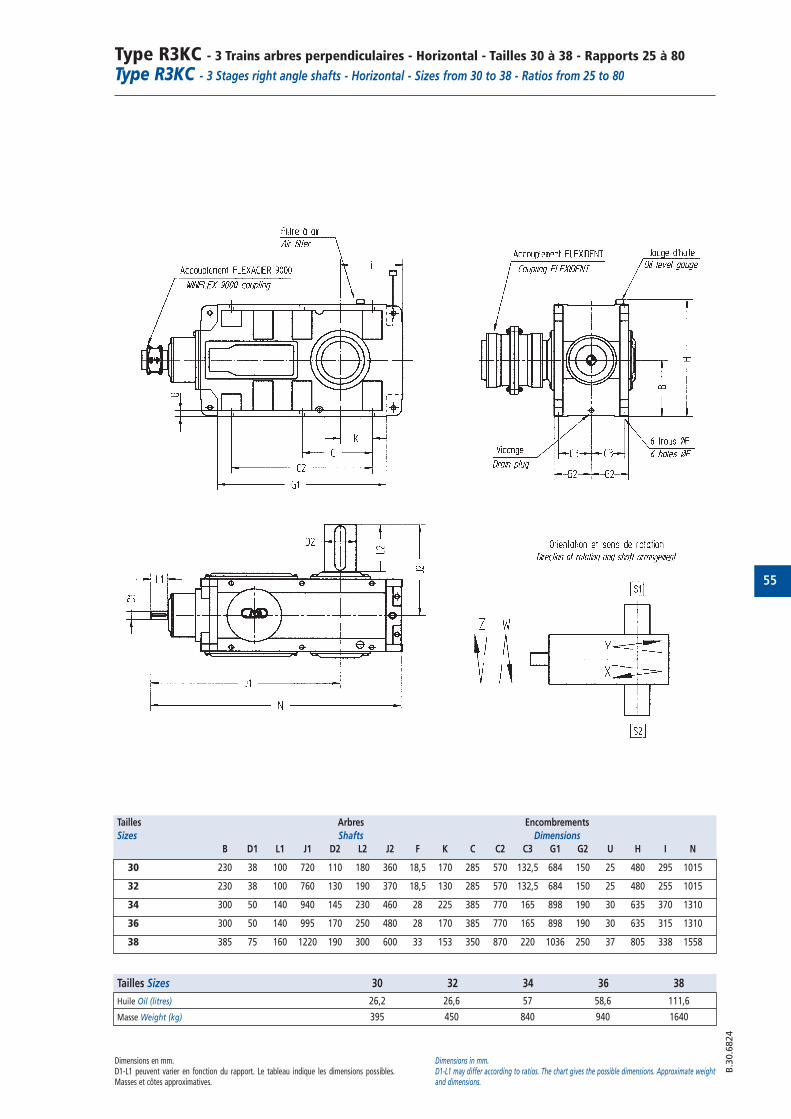
55
Type R3KC - 3 Trains arbres perpendiculaires - Horizontal - Tailles 30 à 38 - Rapports 25 à 80Type R3KC - 3 Stages right angle shafts - Horizontal - Sizes from 30 to 38 - Ratios from 25 to 80
B.3
0.6
824
Dimensions en mm.D1-L1 peuvent varier en fonction du rapport. Le tableau indique les dimensions possibles.Masses et côtes approximatives.
Dimensions in mm.D1-L1 may differ according to ratios. The chart gives the possible dimensions. Approximate weightand dimensions.
Tailles Arbres Encombrements
Sizes Shafts Dimensions
B D1 L1 J1 D2 L2 J2 F K C C2 C3 G1 G2 U H I N
30 230 38 100 720 110 180 360 18,5 170 285 570 132,5 684 150 25 480 295 1015
32 230 38 100 760 130 190 370 18,5 130 285 570 132,5 684 150 25 480 255 1015
34 300 50 140 940 145 230 460 28 225 385 770 165 898 190 30 635 370 1310
36 300 50 140 995 170 250 480 28 170 385 770 165 898 190 30 635 315 1310
38 385 75 160 1220 190 300 600 33 153 350 870 220 1036 250 37 805 338 1558
Tailles Sizes 30 32 34 36 38
Huile Oil (litres) 26,2 26,6 57 58,6 111,6
Masse Weight (kg) 395 450 840 940 1640

56
Type R3KCV - 3 Trains arbres perpendiculaires - Vertical - Tailles 30 à 38 - Rapports 25 à 80
Type R3KCV - 3 Stages right angle shafts - Vertical - Sizes from 30 to 38 - Ratios from 25 to 80
Capacités nominales en kW “PN” ISO 6336* Facteur : Ka=1 SH=1 SF>1,2
“PN” mechanical power ratings in kW ISO 6336* Factor: Ka=1 SH=1 SF>1.2
B.3
0.6
822
Tailles Sizes N1 N2 30 32 34 36 38Rapports Ratios Rpm Rpm
1450 58 69,2 82,5 165 226 37325 960 38 45,8 60,1 109 150 247
725 29 34,6 45,4 82,6 113 1871450 52 64,7 69,2 148 185 333
28 960 34 42,8 45,8 98,2 122 221725 26 32,4 34,6 74,2 92,4 167
1450 45 58,1 69,2 130 174 28632 960 30 38,5 45,8 86 115 189
725 23 29,1 34,6 65 87 1431450 40 51,8 63,9 114 157 259
36 960 27 34,3 42,3 75,8 104 172725 20 25,9 32 57,3 78,4 130
1450 36 45,8 57,4 106 139 29940 960 24 30,3 38 70,2 91,8 152
725 18 22,9 28,7 53,1 69,4 1141450 32 41,6 51,2 93,8 123 216
45 960 21 27,5 33,9 62,1 81,1 143725 16 20,8 25,6 46,9 61,3 108
1450 29 37,8 45,2 82,2 114 18550 960 19 25 29,9 54,4 75,5 123
725 15 18,9 22,6 41,1 57 92,71450 26 33,7 41,6 72,4 99,2 169
56 960 17 22,3 27,5 48 65,7 112725 13 16,8 20,8 36,2 49,6 84,2
1450 23 29,8 37,3 67,1 87,7 14963 960 15 19,7 24,7 44,4 58,1 98,5
725 12 14,9 18,7 33,6 43,9 74,41450 20 33,3 77,5
71 960 14 22 51,3725 10 16,6 38,71450 18 29,4 72,1
80 960 12 19,5 47,7725 9 14,7 36
Puissance thermique en kW "Pt" pour ambiance 20°C."Pt" thermal rating in kW for 20°C ambient.
ATTENTIONPour certains rapports, la vitesse tangentielle peut imposer une injection même si la capacitéthermique est suffisante. Au delà de la capacité thermique ci-dessus, nous utilisons l'injectionavec réfrigérant. Ces éléments ne modifient pas la capacité PN des réducteurs.
ATTENTIONFor some ratios, the velocity requires an oil injection even if thermal capacity is sufficient. Beyondthe above thermal capacity, oil injection with cooling are used. These elements do not modify thePN rating of the reducers.
Refroidissement N1 Tailles Sizes
Type of cooling Rpm 30 32 34 36 38
Sans refroidissement 1450 96,6 96,6 161 161 249
With no additionnal cooling 960 91 91 151 151 235
725 88 88 147 147 227
Avec ventilateur 1450 193 193 322 322 498
With fan cooling 960 150 150 249 249 388
725 133 133 220 220 341
Avec serpentin 1450 301 301 501 501 726
With cooling coil 960 269 269 448 448 649
725 259 259 431 431 626
Avec serpentin et ventilateur 1450 397 397 662 662 974
With fan and cooling coil 960 327 327 546 546 802
725 304 304 505 505 739
*Harnais à denture conique calculée suivant DIN 3990 *Bevel teeth according to DIN 3990
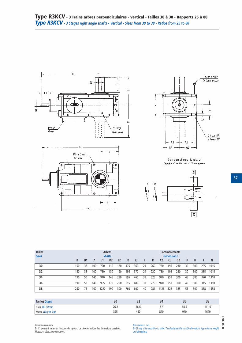
57
Type R3KCV - 3 Trains arbres perpendiculaires - Vertical - Tailles 30 à 38 - Rapports 25 à 80
Type R3KCV - 3 Stages right angle shafts - Vertical - Sizes from 30 to 38 - Ratios from 25 to 80
B.3
0.6
821
Dimensions en mm.D1-L1 peuvent varier en fonction du rapport. Le tableau indique les dimensions possibles.Masses et côtes approximatives.
Dimensions in mm.D1-L1 may differ according to ratios. The chart gives the possible dimensions. Approximate weightand dimensions.
Tailles Arbres Encombrements
Sizes Shafts Dimensions
B D1 L1 J1 D2 L2 J2 J3 F K C2 C3 G2 U H I N
30 150 38 100 720 110 180 475 360 24 260 750 195 230 30 300 295 1015
32 150 38 100 760 130 190 495 370 24 220 750 195 230 30 300 255 1015
34 190 50 140 940 145 230 595 460 33 325 970 253 300 45 380 370 1310
36 190 50 140 995 170 250 615 480 33 270 970 253 300 45 380 315 1310
38 250 75 160 1220 190 300 760 600 40 281 1126 328 385 55 500 338 1558
Tailles Sizes 30 32 34 36 38
Huile Oil (litres) 26,2 26,6 57 58,6 111,6
Masse Weight (kg) 395 450 840 940 1640
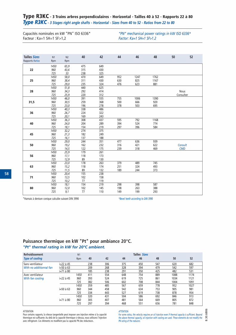
58
Type R3KC - 3 Trains arbres perpendiculaires - Horizontal - Tailles 40 à 52 - Rapports 22 à 80
Type R3KC - 3 Stages right angle shafts - Horizontal - Sizes from 40 to 52 - Ratios from 22 to 80
Capacités nominales en kW “PN” ISO 6336*Facteur : Ka=1 SH=1 SF>1,2
Puissance thermique en kW "Pt" pour ambiance 20°C."Pt" thermal rating in kW for 20°C ambient.
“PN” mechanical power ratings in kW ISO 6336*Factor: Ka=1 SH=1 SF>1.2
ATTENTIONPour certains rapports, la vitesse tangentielle peut imposer une injection même si la capacitéthermique est suffisante. Au delà de la capacité thermique ci-dessus, nous utilisons l'injectionavec réfrigérant. Ces éléments ne modifient pas la capacité PN des réducteurs.
ATTENTIONFor some ratios, the velocity requires an oil injection even if thermal capacity is sufficient. Beyondthe above thermal capacity, oil injection with cooling are used. These elements do not modify thePN rating of the reducers. B
.30.6
806
Tailles Sizes N1 N2 40 42 44 46 48 50 52Rapports Ratios Rpm Rpm
1450 65,9 475 64922 960 43,6 315 430
725 33 238 3251450 58,0 470 649 952 1247 1762
25 960 38,4 311 430 630 825 1167725 29,0 235 324 476 623 8811450 51,8 440 625
28 960 34,3 292 414 Nous725 25,9 220 312 Consulter
1450 46,0 391 555 755 1006 139031,5 960 30,5 259 368 500 666 920
725 23,0 196 278 378 503 6951450 40,3 338 486
36 960 26,7 224 322725 20,1 169 2431450 36,3 308 437 595 792 1168
40 960 24,0 204 289 394 524 774725 18,1 154 219 297 396 5841450 32,2 274 375
45 960 21,3 182 249725 16,1 137 1881450 29,0 244 351 477 636 939
50 960 19,2 162 232 316 421 622 Consult725 14,5 122 175 239 318 469 CMD1450 25,9 179 261
56 960 17,1 118 173725 12,9 89 1301450 23,0 178 263 379 489 745
63 960 15,2 118 174 251 324 493725 11,5 89 132 189 244 3731450 20,4 155 238
71 960 13,5 102 158725 10,2 77 1191450 18,1 154 219 298 398 587
80 960 12,0 102 145 198 263 388725 9,1 77 110 149 199 293
Refroidissement N1 Tailles Sizes
Type of cooling Rpm 40 42 44 46 48 50 52
Sans ventilateur i=22 à 45 238 306 375 450 547 620 682With no additionnal fan i=50 à 63 209 268 328 394 479 542 597
i=71 à 80 185 238 291 350 425 482 531Avec ventilateur 1450 411 554 648 754 889 1088 1174With fan cooling i=22 à 45 960 393 524 619 725 861 1034 1121
725 382 506 602 708 844 1004 10911450 359 485 567 659 778 952 1027
i=50 à 63 960 344 458 542 634 753 905 981725 334 443 527 619 738 878 9541450 320 431 504 586 692 846 913
i=71 à 80 960 305 407 481 564 669 805 872725 297 394 468 551 656 781 848
*Harnais à denture conique calculée suivant DIN 3990 *Bevel teeth according to DIN 3990
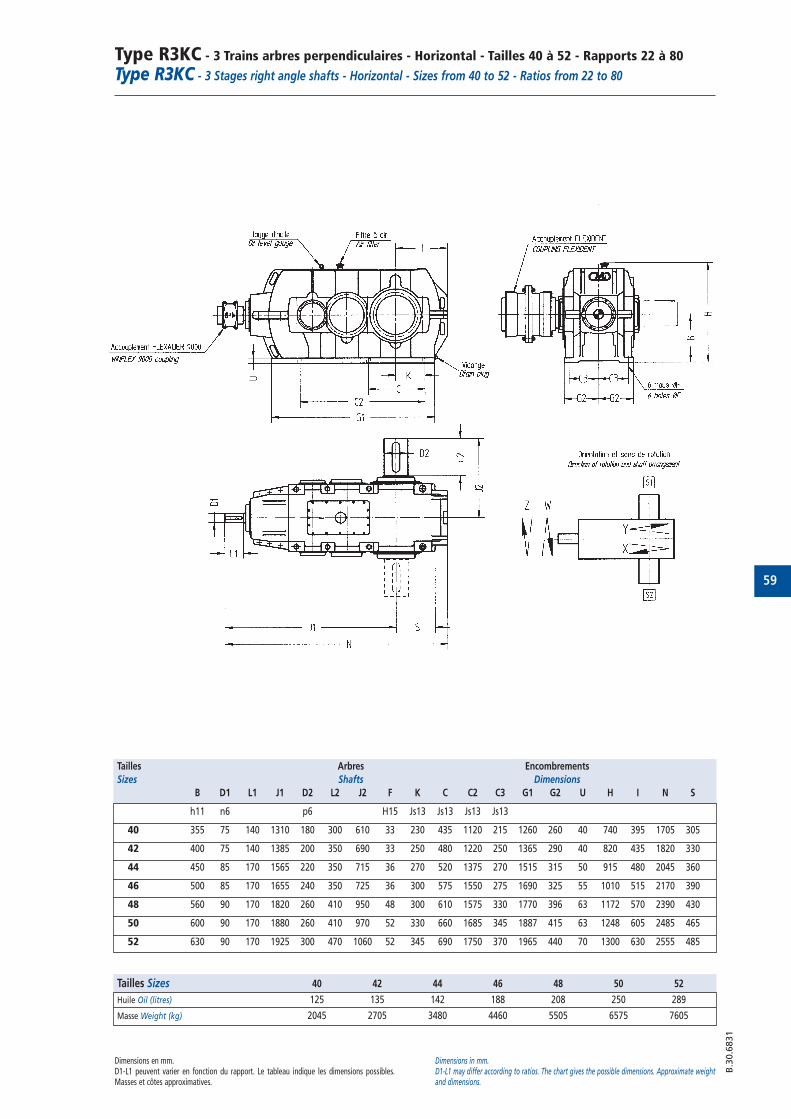
59
Type R3KC - 3 Trains arbres perpendiculaires - Horizontal - Tailles 40 à 52 - Rapports 22 à 80
Type R3KC - 3 Stages right angle shafts - Horizontal - Sizes from 40 to 52 - Ratios from 22 to 80
B.3
0.6
831
Tailles Arbres Encombrements
Sizes Shafts Dimensions
B D1 L1 J1 D2 L2 J2 F K C C2 C3 G1 G2 U H I N S
h11 n6 p6 H15 Js13 Js13 Js13 Js13
40 355 75 140 1310 180 300 610 33 230 435 1120 215 1260 260 40 740 395 1705 305
42 400 75 140 1385 200 350 690 33 250 480 1220 250 1365 290 40 820 435 1820 330
44 450 85 170 1565 220 350 715 36 270 520 1375 270 1515 315 50 915 480 2045 360
46 500 85 170 1655 240 350 725 36 300 575 1550 275 1690 325 55 1010 515 2170 390
48 560 90 170 1820 260 410 950 48 300 610 1575 330 1770 396 63 1172 570 2390 430
50 600 90 170 1880 260 410 970 52 330 660 1685 345 1887 415 63 1248 605 2485 465
52 630 90 170 1925 300 470 1060 52 345 690 1750 370 1965 440 70 1300 630 2555 485
Dimensions en mm.D1-L1 peuvent varier en fonction du rapport. Le tableau indique les dimensions possibles.Masses et côtes approximatives.
Dimensions in mm.D1-L1 may differ according to ratios. The chart gives the possible dimensions. Approximate weightand dimensions.
Tailles Sizes 40 42 44 46 48 50 52
Huile Oil (litres) 125 135 142 188 208 250 289
Masse Weight (kg) 2045 2705 3480 4460 5505 6575 7605

60
Type R3KCV - 3 Trains arbres perpendiculaires - Vertical - Tailles 40 à 52 - Rapports 22 à 80
Type R3KCV - 3 Stages right angle shafts - Vertical - Sizes from 40 to 52 - Ratios from 22 to 80
Capacités nominales en kW “PN” ISO 6336*Facteur : Ka=1 SH=1 SF>1,2
Puissance thermique en kW "Pt" pour ambiance 20°C."Pt" thermal rating in kW for 20°C ambient.
“PN” mechanical power ratings in kW ISO 6336*Factor: Ka=1 SH=1 SF>1.2
ATTENTIONPour certains rapports, la vitesse tangentielle peut imposer une injection même si la capacitéthermique est suffisante. Au delà de la capacité thermique ci-dessus, nous utilisons l'injectionavec réfrigérant. Ces éléments ne modifient pas la capacité PN des réducteurs.
ATTENTIONFor some ratios, the velocity requires an oil injection even if thermal capacity is sufficient. Beyondthe above thermal capacity, oil injection with cooling are used. These elements do not modify thePN rating of the reducers. B
.30.6
814
Tailles Sizes N1 N2 40 42 44 46 48 50 52Rapports Ratios Rpm Rpm
1450 65,9 475 64922 960 43,6 315 430
725 33 238 3251450 58,0 470 649 952 1247 1762
25 960 38,4 311 430 630 825 1167725 29,0 235 324 476 623 8811450 51,8 440 625
28 960 34,3 292 414 Nous725 25,9 220 312 consulter
1450 46,0 391 555 755 1006 139031,5 960 30,5 259 368 500 666 920
725 23,0 196 278 378 503 6951450 40,3 338 486
36 960 26,7 224 322 Consult725 20,1 169 243 CMD1450 36,3 308 437 595 792 1168
40 960 24,0 204 289 394 524 774725 18,1 154 219 297 396 5841450 32,2 274 375
45 960 21,3 182 249725 16,1 137 1881450 29,0 244 351 477 636 939
50 960 19,2 162 232 316 421 622725 14,5 122 175 239 318 4691450 25,9 179 261
56 960 17,1 118 173725 12,9 89 1301450 23,0 178 263 379 489 745
63 960 15,2 118 174 251 324 493725 11,5 89 132 189 244 3731450 20,4 155 238
71 960 13,5 102 158725 10,2 77 1191450 18,1 154 219 298 398 587
80 960 12,0 102 145 198 263 388725 9,1 77 110 149 199 293
Refroidissement N1 Tailles Sizes
Type of cooling Rpm 40 42 44 46 48 50 52
Sans ventilateur i=22 à 45 238 306 375 450 547 620 682With no additionnal fan i=50 à 63 209 268 328 394 479 542 597
i=71 à 80 185 238 291 350 425 482 531Avec ventilateur 1450 411 554 648 754 889 1088 1174With fan cooling i=22 à 45 960 393 524 619 725 861 1034 1121
725 382 506 602 708 844 1004 10911450 359 485 567 659 778 952 1027
i=50 à 63 960 344 458 542 634 753 905 981725 334 443 527 619 738 878 9541450 320 431 504 586 692 846 913
i=71 à 80 960 305 407 481 564 669 805 872725 297 394 468 551 656 781 848
*Harnais à denture conique calculée suivant DIN 3990 *Bevel teeth according to DIN 3990
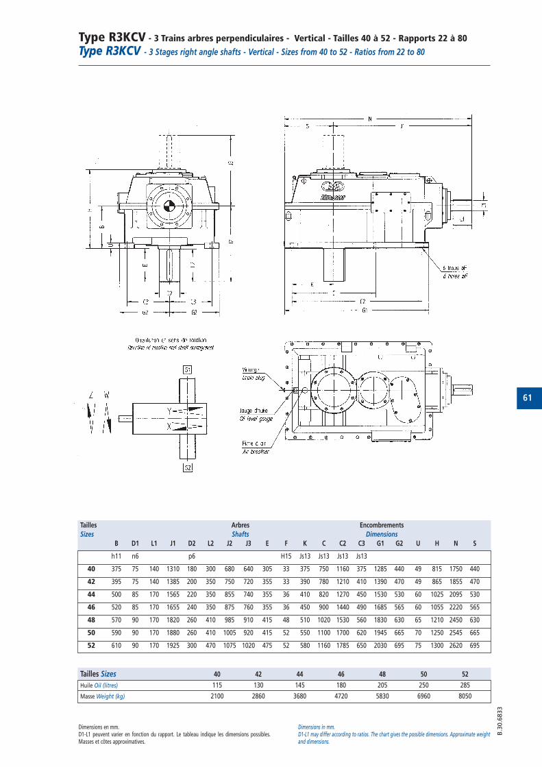
61
Type R3KCV - 3 Trains arbres perpendiculaires - Vertical - Tailles 40 à 52 - Rapports 22 à 80
Type R3KCV - 3 Stages right angle shafts - Vertical - Sizes from 40 to 52 - Ratios from 22 to 80
B.3
0.6
833
Tailles Arbres Encombrements
Sizes Shafts Dimensions
B D1 L1 J1 D2 L2 J2 J3 E F K C C2 C3 G1 G2 U H N S
h11 n6 p6 H15 Js13 Js13 Js13 Js13
40 375 75 140 1310 180 300 680 640 305 33 375 750 1160 375 1285 440 49 815 1750 440
42 395 75 140 1385 200 350 750 720 355 33 390 780 1210 410 1390 470 49 865 1855 470
44 500 85 170 1565 220 350 855 740 355 36 410 820 1270 450 1530 530 60 1025 2095 530
46 520 85 170 1655 240 350 875 760 355 36 450 900 1440 490 1685 565 60 1055 2220 565
48 570 90 170 1820 260 410 985 910 415 48 510 1020 1530 560 1830 630 65 1210 2450 630
50 590 90 170 1880 260 410 1005 920 415 52 550 1100 1700 620 1945 665 70 1250 2545 665
52 610 90 170 1925 300 470 1075 1020 475 52 580 1160 1785 650 2030 695 75 1300 2620 695
Dimensions en mm.D1-L1 peuvent varier en fonction du rapport. Le tableau indique les dimensions possibles.Masses et côtes approximatives.
Dimensions in mm.D1-L1 may differ according to ratios. The chart gives the possible dimensions. Approximate weightand dimensions.
Tailles Sizes 40 42 44 46 48 50 52
Huile Oil (litres) 115 130 145 180 205 250 285
Masse Weight (kg) 2100 2860 3680 4720 5830 6960 8050
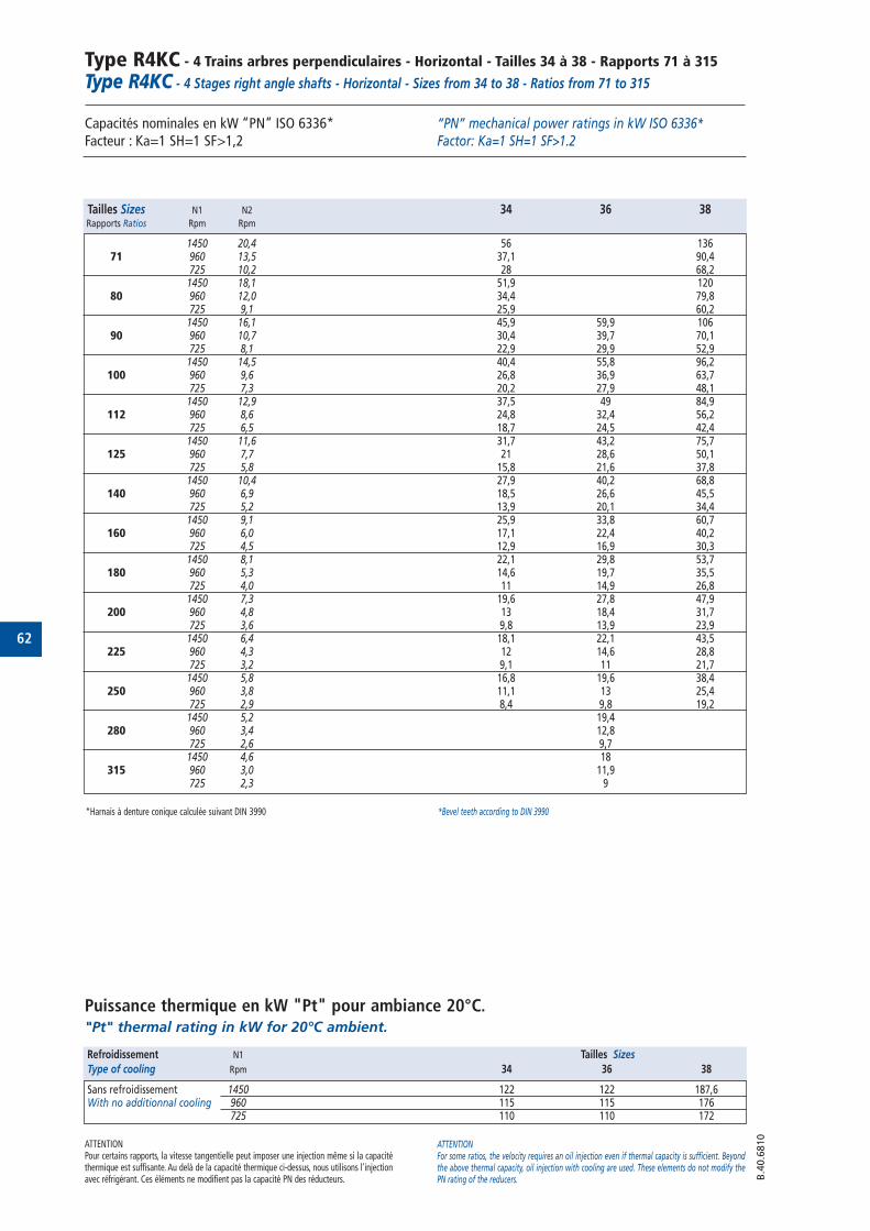
62
Type R4KC - 4 Trains arbres perpendiculaires - Horizontal - Tailles 34 à 38 - Rapports 71 à 315
Type R4KC - 4 Stages right angle shafts - Horizontal - Sizes from 34 to 38 - Ratios from 71 to 315
Capacités nominales en kW “PN” ISO 6336* Facteur : Ka=1 SH=1 SF>1,2
Puissance thermique en kW "Pt" pour ambiance 20°C."Pt" thermal rating in kW for 20°C ambient.
“PN” mechanical power ratings in kW ISO 6336*Factor: Ka=1 SH=1 SF>1.2
ATTENTIONPour certains rapports, la vitesse tangentielle peut imposer une injection même si la capacitéthermique est suffisante. Au delà de la capacité thermique ci-dessus, nous utilisons l'injectionavec réfrigérant. Ces éléments ne modifient pas la capacité PN des réducteurs.
ATTENTIONFor some ratios, the velocity requires an oil injection even if thermal capacity is sufficient. Beyondthe above thermal capacity, oil injection with cooling are used. These elements do not modify thePN rating of the reducers. B
.40.6
810
Tailles Sizes N1 N2 34 36 38Rapports Ratios Rpm Rpm
1450 20,4 56 13671 960 13,5 37,1 90,4
725 10,2 28 68,21450 18,1 51,9 120
80 960 12,0 34,4 79,8725 9,1 25,9 60,2
1450 16,1 45,9 59,9 10690 960 10,7 30,4 39,7 70,1
725 8,1 22,9 29,9 52,91450 14,5 40,4 55,8 96,2
100 960 9,6 26,8 36,9 63,7725 7,3 20,2 27,9 48,1
1450 12,9 37,5 49 84,9112 960 8,6 24,8 32,4 56,2
725 6,5 18,7 24,5 42,41450 11,6 31,7 43,2 75,7
125 960 7,7 21 28,6 50,1725 5,8 15,8 21,6 37,8
1450 10,4 27,9 40,2 68,8140 960 6,9 18,5 26,6 45,5
725 5,2 13,9 20,1 34,41450 9,1 25,9 33,8 60,7
160 960 6,0 17,1 22,4 40,2725 4,5 12,9 16,9 30,3
1450 8,1 22,1 29,8 53,7180 960 5,3 14,6 19,7 35,5
725 4,0 11 14,9 26,81450 7,3 19,6 27,8 47,9
200 960 4,8 13 18,4 31,7725 3,6 9,8 13,9 23,91450 6,4 18,1 22,1 43,5
225 960 4,3 12 14,6 28,8725 3,2 9,1 11 21,71450 5,8 16,8 19,6 38,4
250 960 3,8 11,1 13 25,4725 2,9 8,4 9,8 19,21450 5,2 19,4
280 960 3,4 12,8725 2,6 9,71450 4,6 18
315 960 3,0 11,9725 2,3 9
Refroidissement N1 Tailles Sizes
Type of cooling Rpm 34 36 38
Sans refroidissement 1450 122 122 187,6With no additionnal cooling 960 115 115 176
725 110 110 172
*Harnais à denture conique calculée suivant DIN 3990 *Bevel teeth according to DIN 3990
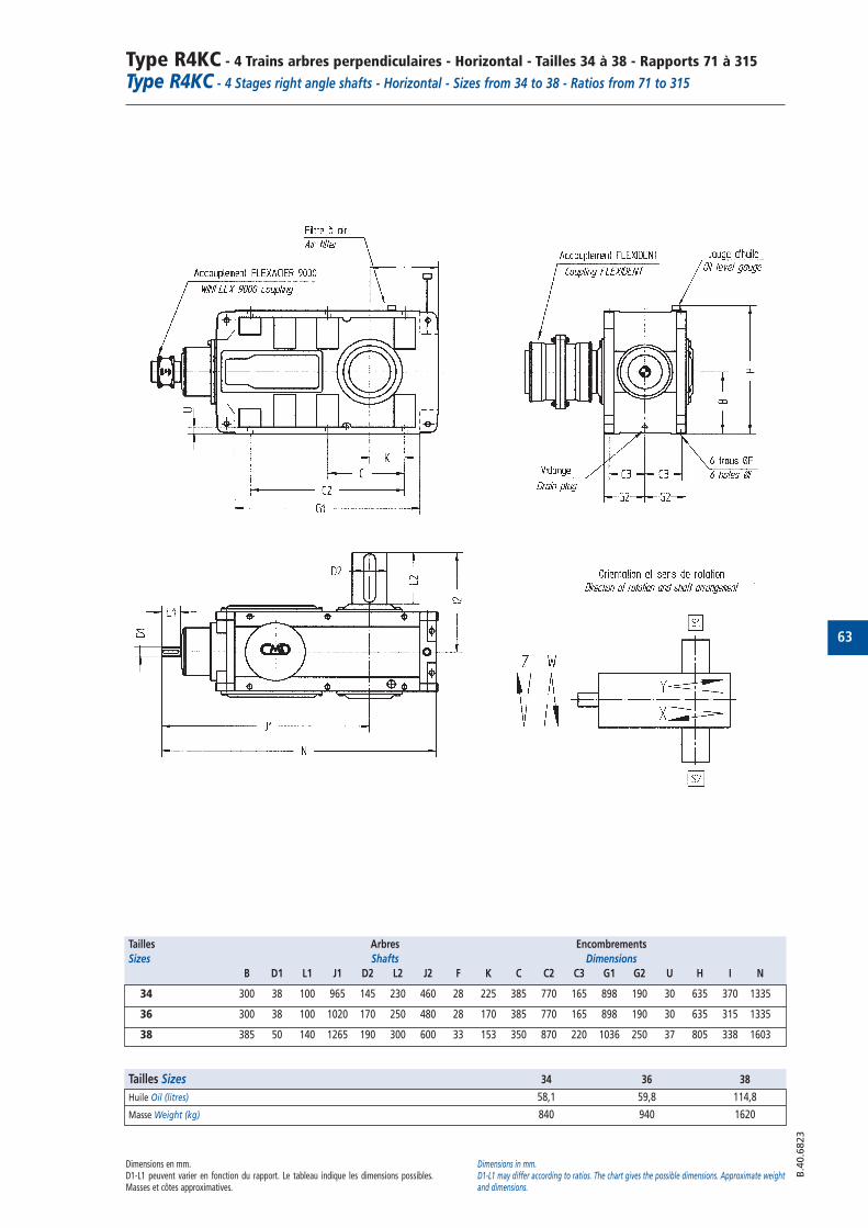
63
Type R4KC - 4 Trains arbres perpendiculaires - Horizontal - Tailles 34 à 38 - Rapports 71 à 315
Type R4KC - 4 Stages right angle shafts - Horizontal - Sizes from 34 to 38 - Ratios from 71 to 315
B.4
0.6
823
Tailles Arbres Encombrements
Sizes Shafts Dimensions
B D1 L1 J1 D2 L2 J2 F K C C2 C3 G1 G2 U H I N
34 300 38 100 965 145 230 460 28 225 385 770 165 898 190 30 635 370 1335
36 300 38 100 1020 170 250 480 28 170 385 770 165 898 190 30 635 315 1335
38 385 50 140 1265 190 300 600 33 153 350 870 220 1036 250 37 805 338 1603
Dimensions en mm.D1-L1 peuvent varier en fonction du rapport. Le tableau indique les dimensions possibles.Masses et côtes approximatives.
Dimensions in mm.D1-L1 may differ according to ratios. The chart gives the possible dimensions. Approximate weightand dimensions.
Tailles Sizes 34 36 38
Huile Oil (litres) 58,1 59,8 114,8
Masse Weight (kg) 840 940 1620

64
Type R4KCV - 4 Trains arbres perpendiculaires - Vertical - Tailles 34 à 38 - Rapports 71 à 315
Type R4KCV - 4 Stages right angle shafts - Vertical - Sizes from 34 to 38 - Ratios from 71 to 315
Capacités nominales en kW “PN” ISO 6336* Facteur : Ka=1 SH=1 SF>1,2
Puissance thermique en kW "Pt" pour ambiance 20°C."Pt" thermal rating in kW for 20°C ambient.
“PN” mechanical power ratings in kW ISO 6336* Factor: Ka=1 SH=1 SF>1.2
ATTENTIONPour certains rapports, la vitesse tangentielle peut imposer une injection même si la capacitéthermique est suffisante. Au delà de la capacité thermique ci-dessus, nous utilisons l'injectionavec réfrigérant. Ces éléments ne modifient pas la capacité PN des réducteurs.
ATTENTIONFor some ratios, the velocity requires an oil injection even if thermal capacity is sufficient. Beyondthe above thermal capacity, oil injection with cooling are used. These elements do not modify thePN rating of the reducers. B
.40.6
811
Tailles Sizes N1 N2 34 36 38Rapports Ratios Rpm Rpm
1450 20,4 56 13671 960 13,5 37,1 90,4
725 10,2 28 68,21450 18,1 51,9 120
80 960 12,0 34,4 79,8725 9,1 25,9 60,2
1450 16,1 45,9 59,9 10690 960 10,7 30,4 39,7 70,1
725 8,1 22,9 29,9 52,91450 14,5 40,4 55,8 96,2
100 960 9,6 26,8 36,9 63,7725 7,3 20,2 27,9 48,1
1450 12,9 37,5 49 84,9112 960 8,6 24,8 32,4 56,2
725 6,5 18,7 24,5 42,41450 11,6 31,7 43,2 75,7
125 960 7,7 21 28,6 50,1725 5,8 15,8 21,6 37,8
1450 10,4 27,9 40,2 68,8140 960 6,9 18,5 26,6 45,5
725 5,2 13,9 20,1 34,41450 9,1 25,9 33,8 60,7
160 960 6,0 17,1 22,4 40,2725 4,5 12,9 16,9 30,3
1450 8,1 22,1 29,8 53,7180 960 5,3 14,6 19,7 35,5
725 4,0 11 14,9 26,81450 7,3 19,6 27,8 47,9
200 960 4,8 13 18,4 31,7725 3,6 9,8 13,9 23,91450 6,4 18,1 22,1 43,5
225 960 4,3 12 14,6 28,8725 3,2 9,1 11 21,71450 5,8 16,8 19,6 38,4
250 960 3,8 11,1 13 25,4725 2,9 8,4 9,8 19,21450 5,2 19,4
280 960 3,4 12,8725 2,6 9,71450 4,6 18
315 960 3,0 11,9725 2,3 9
Refroidissement N1 Tailles Sizes
Type of cooling Rpm 34 36 38
Sans refroidissement 1450 122 122 187,6With no additionnal cooling 960 115 115 176
725 110 110 172
*Harnais à denture conique calculée suivant DIN 3990 *Bevel teeth according to DIN 3990
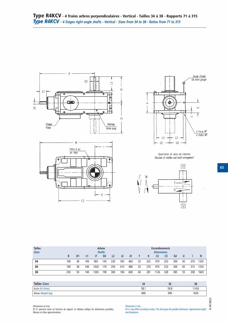
65
Type R4KCV - 4 Trains arbres perpendiculaires - Vertical - Tailles 34 à 38 - Rapports 71 à 315
Type R4KCV - 4 Stages right angle shafts - Vertical - Sizes from 34 to 38 - Ratios from 71 to 315
B.4
0.6
822
Tailles Arbres Encombrements
Sizes Shafts Dimensions
B D1 L1 J1 D2 L2 J2 J3 F K C2 C3 G2 U I N
34 190 38 100 965 145 230 595 460 33 325 970 253 300 45 370 1335
36 190 38 100 1020 170 250 615 480 33 270 970 253 300 45 315 1335
38 250 50 140 1265 190 300 760 600 40 281 1126 328 385 55 338 1603
Dimensions en mm.D1-L1 peuvent varier en fonction du rapport. Le tableau indique les dimensions possibles.Masses et côtes approximatives.
Dimensions in mm.D1-L1 may differ according to ratios. The chart gives the possible dimensions. Approximate weightand dimensions.
Tailles Sizes 34 36 38
Huile Oil (litres) 58,1 59,8 114,8
Masse Weight (kg) 840 940 1620
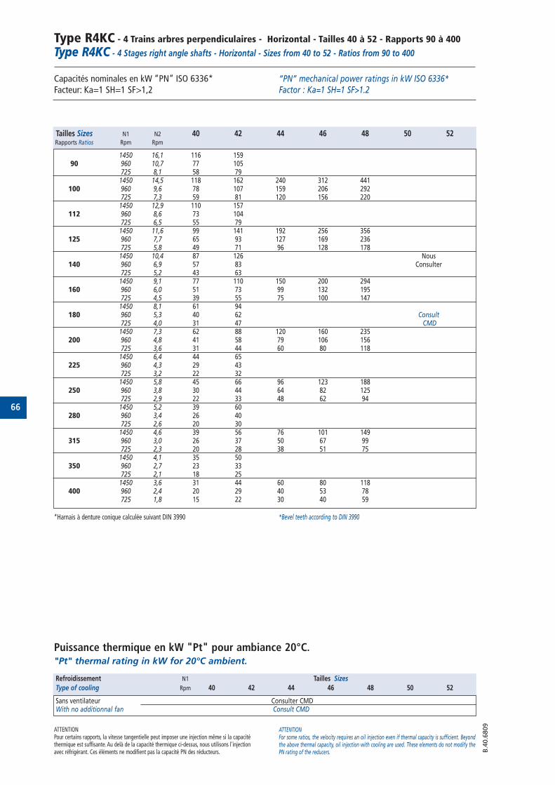
66
Type R4KC - 4 Trains arbres perpendiculaires - Horizontal - Tailles 40 à 52 - Rapports 90 à 400
Type R4KC - 4 Stages right angle shafts - Horizontal - Sizes from 40 to 52 - Ratios from 90 to 400
Capacités nominales en kW “PN” ISO 6336*Facteur: Ka=1 SH=1 SF>1,2
Puissance thermique en kW "Pt" pour ambiance 20°C."Pt" thermal rating in kW for 20°C ambient.
“PN” mechanical power ratings in kW ISO 6336*Factor : Ka=1 SH=1 SF>1.2
ATTENTIONPour certains rapports, la vitesse tangentielle peut imposer une injection même si la capacitéthermique est suffisante. Au delà de la capacité thermique ci-dessus, nous utilisons l'injectionavec réfrigérant. Ces éléments ne modifient pas la capacité PN des réducteurs.
ATTENTIONFor some ratios, the velocity requires an oil injection even if thermal capacity is sufficient. Beyondthe above thermal capacity, oil injection with cooling are used. These elements do not modify thePN rating of the reducers. B
.40.6
809
Tailles Sizes N1 N2 40 42 44 46 48 50 52Rapports Ratios Rpm Rpm
1450 16,1 116 15990 960 10,7 77 105
725 8,1 58 791450 14,5 118 162 240 312 441
100 960 9,6 78 107 159 206 292725 7,3 59 81 120 156 2201450 12,9 110 157
112 960 8,6 73 104725 6,5 55 791450 11,6 99 141 192 256 356
125 960 7,7 65 93 127 169 236725 5,8 49 71 96 128 1781450 10,4 87 126 Nous
140 960 6,9 57 83 Consulter725 5,2 43 631450 9,1 77 110 150 200 294
160 960 6,0 51 73 99 132 195725 4,5 39 55 75 100 1471450 8,1 61 94
180 960 5,3 40 62 Consult725 4,0 31 47 CMD1450 7,3 62 88 120 160 235
200 960 4,8 41 58 79 106 156725 3,6 31 44 60 80 1181450 6,4 44 65
225 960 4,3 29 43725 3,2 22 321450 5,8 45 66 96 123 188
250 960 3,8 30 44 64 82 125725 2,9 22 33 48 62 941450 5,2 39 60
280 960 3,4 26 40725 2,6 20 301450 4,6 39 56 76 101 149
315 960 3,0 26 37 50 67 99725 2,3 20 28 38 51 751450 4,1 35 50
350 960 2,7 23 33725 2,1 18 251450 3,6 31 44 60 80 118
400 960 2,4 20 29 40 53 78725 1,8 15 22 30 40 59
Refroidissement N1 Tailles Sizes
Type of cooling Rpm 40 42 44 46 48 50 52
Sans ventilateur Consulter CMDWith no additionnal fan Consult CMD
*Harnais à denture conique calculée suivant DIN 3990 *Bevel teeth according to DIN 3990
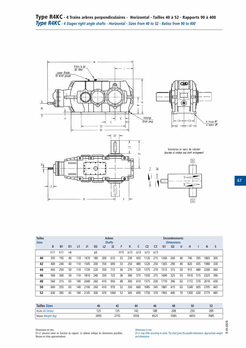
67
Type R4KC - 4 Trains arbres perpendiculaires - Horizontal - Tailles 40 à 52 - Rapports 90 à 400
Type R4KC - 4 Stages right angle shafts - Horizontal - Sizes from 40 to 52 - Ratios from 90 to 400
B.4
0.6
828
Tailles Arbres Encombrements
Sizes Shafts Dimensions
B B1 D1 L1 J1 D2 L2 J2 F K C C2 C3 G1 G2 U H I N S
h11 h11 n6 p6 H15 Js13 Js13 Js13 Js13
40 355 195 40 110 1470 180 300 610 33 230 435 1120 215 1260 260 40 740 395 1865 305
42 400 240 40 110 1545 200 350 690 33 250 480 1220 250 1365 290 40 820 435 1980 330
44 450 250 50 110 1720 220 350 715 36 270 520 1375 270 1515 315 50 915 480 2200 360
46 500 300 50 110 1810 240 350 725 36 300 575 1550 275 1690 325 55 1010 515 2325 390
48 560 315 65 140 2040 260 410 950 48 300 610 1575 330 1770 396 63 1172 570 2610 430
50 600 355 65 140 2100 260 410 970 52 330 660 1685 345 1887 415 63 1248 605 2705 465
52 630 385 65 140 2145 300 470 1060 52 345 690 1750 370 1965 440 70 1300 630 2775 485
Dimensions en mm.D1-L1 peuvent varier en fonction du rapport. Le tableau indique les dimensions possibles.Masses et côtes approximatives.
Dimensions in mm.D1-L1 may differ according to ratios. The chart gives the possible dimensions. Approximate weightand dimensions.
Tailles Sizes 40 42 44 46 48 50 52
Huile Oil (litres) 125 135 142 188 208 250 289
Masse Weight (kg) 2095 2755 3550 4525 5585 6655 7685
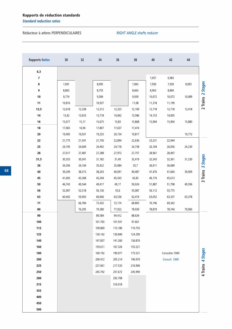
68
Rapports de réduction standards
Standard reduction ratios
Réducteur à arbres PERPENDICULAIRES RIGHT ANGLE shafts reducer
Rapports Ratios 30 32 34 36 38 40 42 44
6,3
7 7,057 6,983
8 7,691 8,095 7,842 7,930 7,930 8,093
9 8,863 8,755 8,663 8,963 8,869
10 9,774 9,584 9,939 10,072 10,072 10,089
11 10,816 10,937 11,08 11,318 11,199
12,5 12,018 12,338 12,312 12,323 12,109 12,718 12,718 12,418
14 13,42 13,653 13,718 14,062 13,586 14,153 14,005
16 15,077 15,17 15,675 15,83 15,868 15,904 15,904 15,880
18 17,065 16,94 17,807 17,637 17,474
20 19,495 19,031 19,225 20,154 19,817 19,772
22 21,775 21,541 21,756 22,894 22,636 23,231 22,944
25 24,195 24,609 24,492 24,718 24,738 26,104 26,056 24,230
28 27,017 27,487 27,288 27,972 27,757 28,961 28,497
31,5 30,353 30,541 31,182 31,49 32,419 32,543 32,361 31,230
36 34,356 34,104 35,422 35,084 35,7 36,911 36,689
40 39,249 38,315 38,243 40,091 40,487 41,476 41,664 39,909
45 41,605 43,368 43,244 45,543 42,83 46,176 45,613
50 46,743 49,544 49,417 49,17 50,024 51,887 51,798 49,596
56 52,907 52,518 56,136 55,6 55,087 56,112 55,775
63 60,442 59,003 60,606 63,536 62,474 63,052 63,337 63,378
71 66,784 73.432 72,174 68.805 70,196 69,342
80 76,295 79.280 77,922 78.030 78,879 78,744 79,960
90 89.584 94.412 88.634
100 101.765 101.931 97.661
112 109.869 115.180 110.755
125 130.142 130.840 124.290
140 147.837 141.260 136.870
160 159.611 167.326 155.221
180 169.192 190.077 175.521 Consulter CMD
200 200.412 205.214 196.970 Consult CMD
225 227.661 217.533 216.906
250 245.792 257.672 245.990
280 292.708
315 316.018
355
400
450
500
4 Tr
ains
4 S
tage
s3
Trai
ns 3
Sta
ges
2 Tr
ains
2 S
tage
s
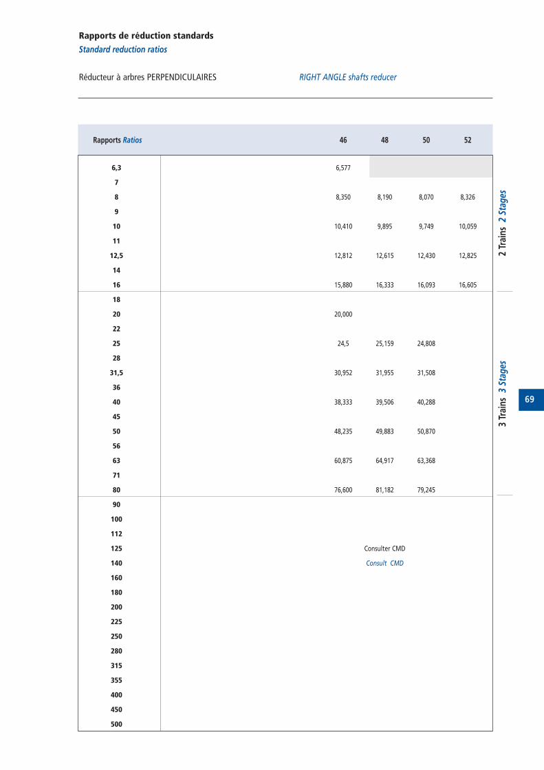
69
Rapports de réduction standards
Standard reduction ratios
Réducteur à arbres PERPENDICULAIRES RIGHT ANGLE shafts reducer
Rapports Ratios 46 48 50 52
6,3 6,577
7
8 8,350 8,190 8,070 8,326
9
10 10,410 9,895 9,749 10,059
11
12,5 12,812 12,615 12,430 12,825
14
16 15,880 16,333 16,093 16,605
18
20 20,000
22
25 24,5 25,159 24,808
28
31,5 30,952 31,955 31,508
36
40 38,333 39,506 40,288
45
50 48,235 49,883 50,870
56
63 60,875 64,917 63,368
71
80 76,600 81,182 79,245
90
100
112
125 Consulter CMD
140 Consult CMD
160
180
200
225
250
280
315
355
400
450
500
3 Tr
ains
3 S
tage
s2
Trai
ns 2
Sta
ges
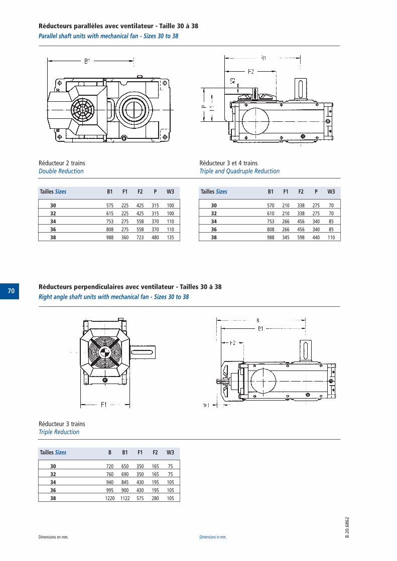
70
Réducteurs parallèles avec ventilateur - Taille 30 à 38
Parallel shaft units with mechanical fan - Sizes 30 to 38
Réducteur 2 trainsDouble Reduction
Réducteur 3 et 4 trainsTriple and Quadruple Reduction
B.2
0.6
862
Tailles Sizes B1 F1 F2 P W3
30 575 225 425 315 100
32 615 225 425 315 100
34 753 275 558 370 110
36 808 275 558 370 110
38 988 360 723 480 135
Tailles Sizes B1 F1 F2 P W3
30 570 210 338 275 70
32 610 210 338 275 70
34 753 266 456 340 85
36 808 266 456 340 85
38 988 345 598 440 110
Réducteurs perpendiculaires avec ventilateur - Tailles 30 à 38
Right angle shaft units with mechanical fan - Sizes 30 to 38
Réducteur 3 trainsTriple Reduction
Tailles Sizes B B1 F1 F2 W3
30 720 650 350 165 75
32 760 690 350 165 75
34 940 845 430 195 105
36 995 900 430 195 105
38 1220 1122 575 280 105
Dimensions en mm. Dimensions in mm.
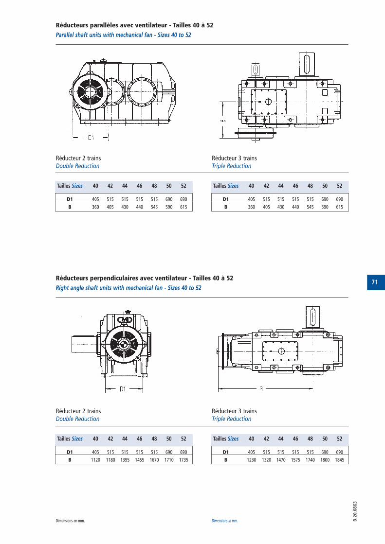
71
B.2
0.6
863
Réducteurs parallèles avec ventilateur - Tailles 40 à 52
Parallel shaft units with mechanical fan - Sizes 40 to 52
Réducteur 2 trainsDouble Reduction
Réducteur 3 trainsTriple Reduction
Tailles Sizes 40 42 44 46 48 50 52
D1 405 515 515 515 515 690 690
B 360 405 430 440 545 590 615
Tailles Sizes 40 42 44 46 48 50 52
D1 405 515 515 515 515 690 690
B 360 405 430 440 545 590 615
Réducteurs perpendiculaires avec ventilateur - Tailles 40 à 52
Right angle shaft units with mechanical fan - Sizes 40 to 52
Réducteur 2 trainsDouble Reduction
Réducteur 3 trainsTriple Reduction
Tailles Sizes 40 42 44 46 48 50 52
D1 405 515 515 515 515 690 690
B 1120 1180 1395 1455 1670 1710 1735
Tailles Sizes 40 42 44 46 48 50 52
D1 405 515 515 515 515 690 690
B 1230 1320 1470 1575 1740 1800 1845
Dimensions en mm. Dimensions in mm.
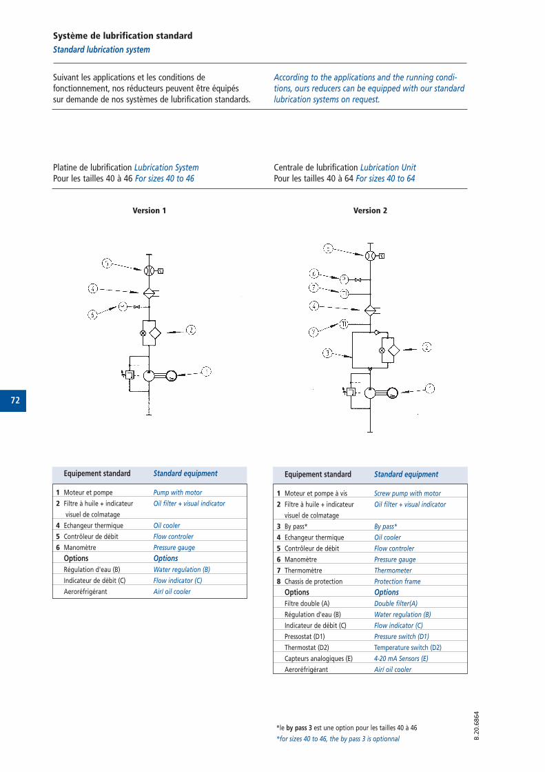
72
Système de lubrification standard
Standard lubrication system
Suivant les applications et les conditions defonctionnement, nos réducteurs peuvent être équipés sur demande de nos systèmes de lubrification standards.
According to the applications and the running condi-tions, ours reducers can be equipped with our standardlubrication systems on request.
B.2
0.6
864
Equipement standard Standard equipment
1 Moteur et pompe Pump with motor
2 Filtre à huile + indicateur Oil filter + visual indicator
visuel de colmatage
4 Echangeur thermique Oil cooler
5 Contrôleur de débit Flow controler
6 Manomètre Pressure gauge
Options Options
Régulation d'eau (B) Water regulation (B)
Indicateur de débit (C) Flow indicator (C)
Aeroréfrigérant Air/ oil cooler
Equipement standard Standard equipment
1 Moteur et pompe à vis Screw pump with motor
2 Filtre à huile + indicateur Oil filter + visual indicator
visuel de colmatage
3 By pass* By pass*
4 Echangeur thermique Oil cooler
5 Contrôleur de débit Flow controler
6 Manomètre Pressure gauge
7 Thermomètre Thermometer
8 Chassis de protection Protection frame
Options Options
Filtre double (A) Double filter(A)
Régulation d'eau (B) Water regulation (B)
Indicateur de débit (C) Flow indicator (C)
Pressostat (D1) Pressure switch (D1)
Thermostat (D2) Temperature switch (D2)
Capteurs analogiques (E) 4-20 mA Sensors (E)
Aeroréfrigérant Air/ oil cooler
Platine de lubrification Lubrication SystemPour les tailles 40 à 46 For sizes 40 to 46
Centrale de lubrification Lubrication UnitPour les tailles 40 à 64 For sizes 40 to 64
Version 1 Version 2
*le by pass 3 est une option pour les tailles 40 à 46
*for sizes 40 to 46, the by pass 3 is optionnal
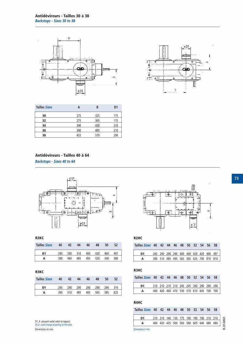
73
B.2
0.6
860
Antidévireurs - Tailles 30 à 38Backstops - Sizes 30 to 38
Tailles Sizes A B D1
30 275 325 175
32 275 365 175
34 340 430 210
36 340 485 210
38 433 570 290
Antidévireurs - Tailles 40 à 64
Backstops - Sizes 40 to 64
R2KC
Tailles Sizes 40 42 44 46 48 50 52
D1 290 290 310 400 420 460 497
A 390 460 485 495 520 540 580
R2HC
Tailles Sizes 40 42 44 46 48 50 52 54 56 58
D1 245 290 290 290 400 400 420 420 460 497
A 390 510 485 495 565 585 625 700 810 810
R3KC
Tailles Sizes 40 42 44 46 48 50 52
D1 245 290 290 290 290 290 310
A 390 510 485 495 565 585 625
R4HC
Tailles Sizes 40 42 44 46 48 50 52 54 56 58
D1 210 210 140 150 175 190 190 190 210 210
A 400 420 425 500 560 580 605 640 680 680
R3HC
Tailles Sizes 40 42 44 46 48 50 52 54 56 58
D1 210 210 210 210 245 245 290 290 290 290
A 400 420 460 470 550 570 610 645 700 700
D1, A peuvent varier selon le rapportD1,A could change according to the ratio
Dimensions en mm. Dimensions in mm.
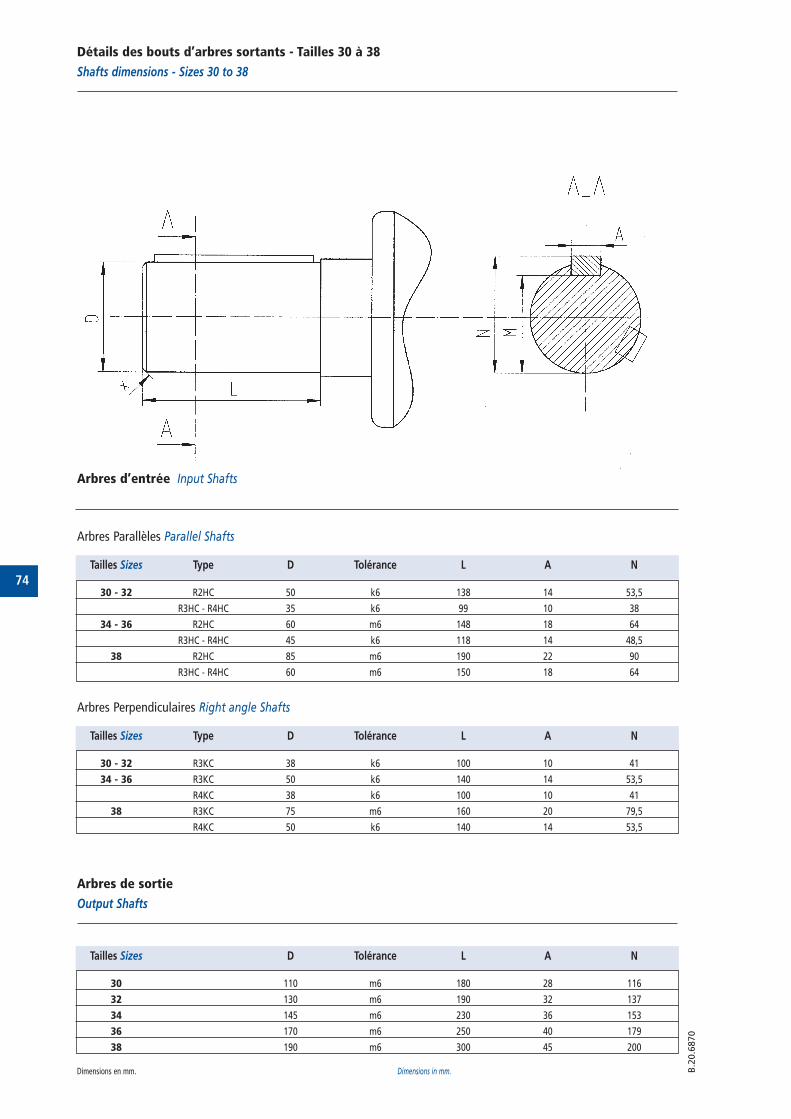
74
Détails des bouts d’arbres sortants - Tailles 30 à 38
Shafts dimensions - Sizes 30 to 38
B.2
0.6
870
Tailles Sizes Type D Tolérance L A N
30 - 32 R2HC 50 k6 138 14 53,5
R3HC - R4HC 35 k6 99 10 38
34 - 36 R2HC 60 m6 148 18 64
R3HC - R4HC 45 k6 118 14 48,5
38 R2HC 85 m6 190 22 90
R3HC - R4HC 60 m6 150 18 64
Arbres d’entrée Input Shafts
Arbres Parallèles Parallel Shafts
Tailles Sizes Type D Tolérance L A N
30 - 32 R3KC 38 k6 100 10 41
34 - 36 R3KC 50 k6 140 14 53,5
R4KC 38 k6 100 10 41
38 R3KC 75 m6 160 20 79,5
R4KC 50 k6 140 14 53,5
Arbres Perpendiculaires Right angle Shafts
Tailles Sizes D Tolérance L A N
30 110 m6 180 28 116
32 130 m6 190 32 137
34 145 m6 230 36 153
36 170 m6 250 40 179
38 190 m6 300 45 200
Arbres de sortie
Output Shafts
Dimensions en mm. Dimensions in mm.
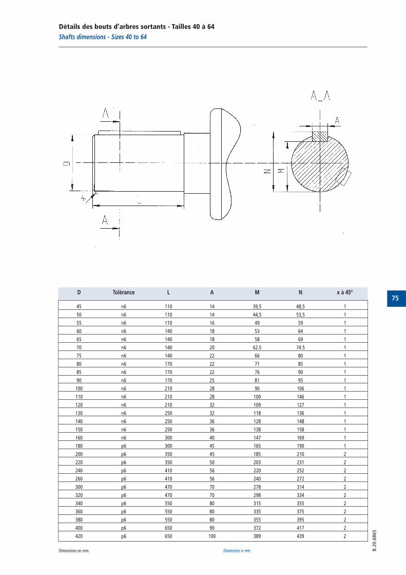
75
B.2
0.6
865
D Tolérance L A M N x à 45°
45 n6 110 14 39,5 48,5 1
50 n6 110 14 44,5 53,5 1
55 n6 110 16 49 59 1
60 n6 140 18 53 64 1
65 n6 140 18 58 69 1
70 n6 140 20 62.5 74.5 1
75 n6 140 22 66 80 1
80 n6 170 22 71 85 1
85 n6 170 22 76 90 1
90 n6 170 25 81 95 1
100 n6 210 28 90 106 1
110 n6 210 28 100 146 1
120 n6 210 32 109 127 1
130 n6 250 32 118 136 1
140 n6 250 36 128 148 1
150 n6 250 36 138 158 1
160 n6 300 40 147 169 1
180 p6 300 45 165 190 1
200 p6 350 45 185 210 2
220 p6 350 50 203 231 2
240 p6 410 56 220 252 2
260 p6 410 56 240 272 2
300 p6 470 70 278 314 2
320 p6 470 70 298 334 2
340 p6 550 80 315 355 2
360 p6 550 80 335 375 2
380 p6 550 80 355 395 2
400 p6 650 90 372 417 2
420 p6 650 100 389 439 2
Détails des bouts d’arbres sortants - Tailles 40 à 64
Shafts dimensions - Sizes 40 to 64
Dimensions en mm. Dimensions in mm.
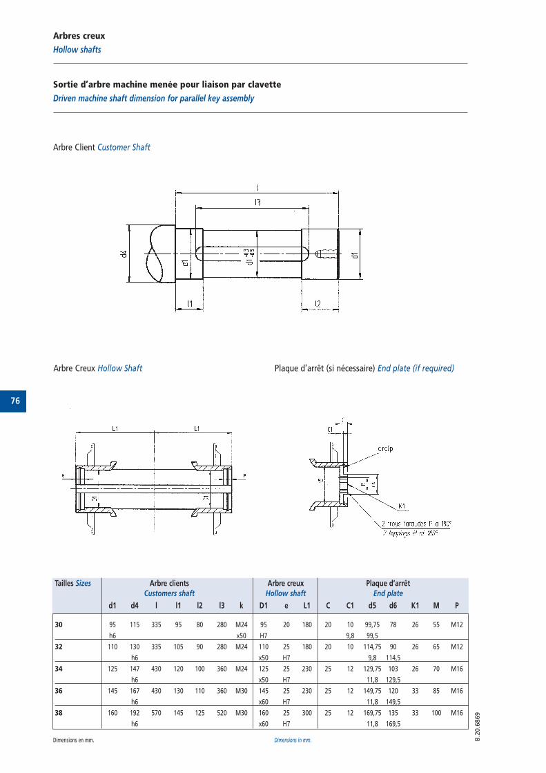
76
Arbres creux
Hollow shafts
Sortie d’arbre machine menée pour liaison par clavette
Driven machine shaft dimension for parallel key assembly
B.2
0.6
869
Plaque d’arrêt (si nécessaire) End plate (if required)
Arbre Client Customer Shaft
Arbre Creux Hollow Shaft
Tailles Sizes Arbre clients Arbre creux Plaque d’arrêtCustomers shaft Hollow shaft End plate
d1 d4 l l1 l2 l3 k D1 e L1 C C1 d5 d6 K1 M P
30 95 115 335 95 80 280 M24 95 20 180 20 10 99,75 78 26 55 M12
h6 x50 H7 9,8 99,5
32 110 130 335 105 90 280 M24 110 25 180 20 10 114,75 90 26 65 M12
h6 x50 H7 9,8 114,5
34 125 147 430 120 100 360 M24 125 25 230 25 12 129,75 103 26 70 M16
h6 x50 H7 11,8 129,5
36 145 167 430 130 110 360 M30 145 25 230 25 12 149,75 120 33 85 M16
h6 x60 H7 11,8 149,5
38 160 192 570 145 125 520 M30 160 25 300 25 12 169,75 135 33 100 M16
h6 x60 H7 11,8 169,5
Dimensions en mm. Dimensions in mm.
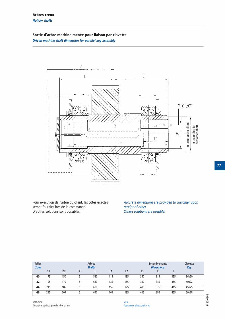
77
B.2
0.6
868
Arbres creux
Hollow shafts
Sortie d’arbre machine menée pour liaison par clavette
Driven machine shaft dimension for parallel key assembly
Pour exécution de l’arbre du client, les côtes exactesseront fournies lors de la commande.D’autres solutions sont possibles.
Tailles Arbres Encombrements Clavette
Sizes Shafts Dimensions Key
D1 D2 X L L1 L2 L3 E J
40 175 150 5 580 115 135 360 315 355 36x20
42 195 170 5 630 135 155 380 345 385 40x22
44 215 185 5 680 155 175 400 375 415 45x25
46 235 205 5 690 165 185 415 385 455 50x28
Accurate dimensions are provided to customer uponreceipt of order.Others solutions are possible.
ATTENTIONDimensions et côtes approximatives en mm.
NOTEApproximate dimensions in mm.
ø se
lon a
rbre
clie
nt
ø ac
cord
ing t
o cu
stom
er s
haf
t
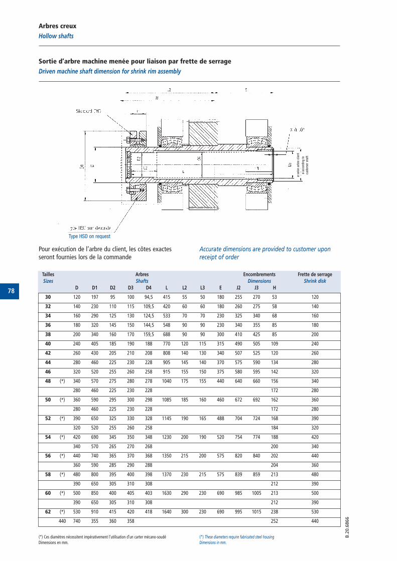
78
Arbres creux
Hollow shafts
Sortie d’arbre machine menée pour liaison par frette de serrage
Driven machine shaft dimension for shrink rim assembly
B.2
0.6
866
Pour exécution de l’arbre du client, les côtes exactesseront fournies lors de la commande
Accurate dimensions are provided to customer uponreceipt of order
Tailles Arbres Encombrements Frette de serrage
Sizes Shafts Dimensions Shrink disk
D D1 D2 D3 D4 L L2 L3 E J2 J3 H
30 120 197 95 100 94,5 415 55 50 180 255 270 53 120
32 140 230 110 115 109,5 420 60 60 180 260 275 58 140
34 160 290 125 130 124,5 533 70 70 230 325 340 68 160
36 180 320 145 150 144,5 548 90 90 230 340 355 85 180
38 200 340 160 170 159,5 688 90 90 300 410 425 85 200
40 240 405 185 190 188 770 120 115 315 490 505 109 240
42 260 430 205 210 208 808 140 130 340 507 525 120 260
44 280 460 225 230 228 905 145 140 370 575 590 134 280
46 320 520 255 260 258 915 155 150 375 580 595 142 320
48 (*) 340 570 275 280 278 1040 175 155 440 640 660 156 340
280 460 225 230 228 172 280
50 (*) 360 590 295 300 298 1085 185 160 460 672 692 162 360
280 460 225 230 228 172 280
52 (*) 390 650 325 330 328 1145 190 165 488 704 724 168 390
320 520 255 260 258 184 320
54 (*) 420 690 345 350 348 1230 200 190 520 754 774 188 420
340 570 265 270 268 200 340
56 (*) 440 740 365 370 368 1350 215 200 575 820 840 202 440
360 590 285 290 288 204 360
58 (*) 480 800 395 400 398 1370 230 215 575 839 859 213 480
390 650 305 310 308 212 390
60 (*) 500 850 400 405 403 1630 290 230 690 985 1005 213 500
390 650 305 310 308 212 390
62 (*) 530 910 415 420 418 1640 300 230 690 995 1015 238 530
440 740 355 360 358 252 440
(*) Ces diamètres nécessitent impérativement l’utilisation d’un carter mécano-soudéDimensions en mm.
(*) These diameters require fabricated steel housingDimensions in mm.
ø se
lon a
rbre
clie
nt
ø ac
cord
ing t
o
cust
omer
shaf
t
Type HSD on request
79
B.4
0.6
835
Montage - InstallationMounting - Installation
Avant d’être emballés ou expédiés, les réducteurs CMDont subi un essai à vide en usine ainsi qu’un test deconformité attestant le respect du cahier des chargesclient.Les accouplements FLEXACIER 9000 et FLEXIDENTpeuvent être montés sur les arbres des réducteurs.
1 - InstallationCelle-ci doit se faire sur massif béton rigide et planavec de préférence interposition de fers ou de plotsnoyés, éventuellement sur une charpente métallique.La liaison avec les organes moteur et récepteur doitêtre assurée par des accouplements FLEXACIER 9000et FLEXIDENT.Le montage sur les arbres des accouplements, depoulie ou de tout autre organe de liaison appelle ungrand soin afin d'éviter les chocs. Lors de la mise enplace, les arbres doivent être alignés soigneusementavec les arbres moteur et récepteur en tenant comptedes instructions de montage des accouplements.Nos appareils comportent des plages de vérification deniveau qu'il convient de contrôler lors du serrage desboulons de fixation sur le plan de pose. Toute variationde niveau indique une déformation du carter à corrigerpar un calage approprié.
2 - LubrificationNos appareils sont livrés sans huile. Il appartient doncà l'utilisateur de procéder au remplissage enrespectant les consignes du cahier d'instruction remislors de la livraison du réducteur.
Before being packed or dispatched, CMD gearboxes aresubmitted to a bench test as well as a conformity test inaccordance with customer specifications.WINFLEX 9000 AND FLEXIDENT couplings can be fittedon gearboxes shafts.
1- InstallationThe unit must be rigidly fixed, either on a concrete bed,preferably reinforced, or with sunken studs, or on ametal frame.In so far as possible, the unit should be coupled withthe motor and the driven unit by means of a flexiblecoupling WINFLEX 9000 or gear coupling FLEXIDENT. We strongly advise against the use of hammering forinstallation (or erection) coupling, pulleys or any othercoupling devices onto shafts.During positioning, the shafts should be carefullyaligned with the motor and driven unit shafts,following the instructions for mounting the couplings.Some units are provided with level checking plateswhich should themselves be checked when tighteningthe foundation bolts. Any variation in level indicatesdistorsion of the gear case, which should be correctedby suitable packing.
2- LubricationOur units are supplied without oil, and it is thereforethe responsibility of the user to fill them with thecorrect amount of oil required for operation.
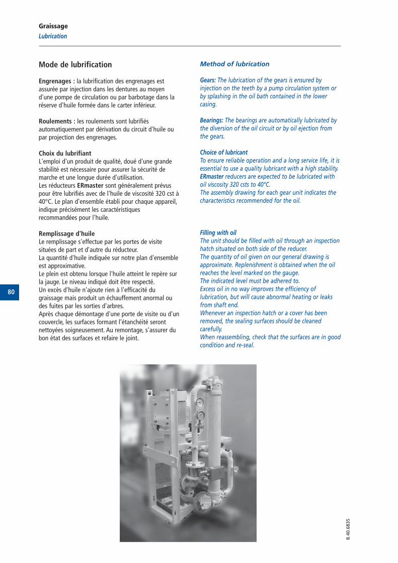
80
B.4
0.6
835
Graissage
Lubrication
Mode de lubrification
Engrenages : la lubrification des engrenages estassurée par injection dans les dentures au moyend'une pompe de circulation ou par barbotage dans laréserve d'huile formée dans le carter inférieur.
Roulements : les roulements sont lubrifiésautomatiquement par dérivation du circuit d'huile oupar projection des engrenages.
Choix du lubrifiantL'emploi d'un produit de qualité, doué d'une grandestabilité est nécessaire pour assurer la sécurité demarche et une longue durée d'utilisation.Les réducteurs ERmaster sont généralement prévuspour être lubrifiés avec de l'huile de viscosité 320 cst à40°C. Le plan d'ensemble établi pour chaque appareil,indique précisément les caractéristiquesrecommandées pour l'huile.
Remplissage d'huileLe remplissage s'effectue par les portes de visitesituées de part et d'autre du réducteur.La quantité d'huile indiquée sur notre plan d'ensembleest approximative.Le plein est obtenu lorsque l'huile atteint le repère surla jauge. Le niveau indiqué doit être respecté.Un excès d'huile n'ajoute rien à l'efficacité dugraissage mais produit un échauffement anormal oudes fuites par les sorties d'arbres.Après chaque démontage d'une porte de visite ou d'uncouvercle, les surfaces formant l’étanchéité serontnettoyées soigneusement. Au remontage, s'assurer dubon état des surfaces et refaire le joint.
Method of lubrication
Gears: The lubrication of the gears is ensured byinjection on the teeth by a pump circulation system orby splashing in the oil bath contained in the lowercasing.
Bearings: The bearings are automatically lubricated bythe diversion of the oil circuit or by oil ejection fromthe gears.
Choice of lubricantTo ensure reliable operation and a long service life, it isessential to use a quality lubricant with a high stability.ERmaster reducers are expected to be lubricated withoil viscosity 320 csts to 40°C.The assembly drawing for each gear unit indicates thecharacteristics recommended for the oil.
Filling with oilThe unit should be filled with oil through an inspectionhatch situated on both side of the reducer.The quantity of oil given on our general drawing isapproximate. Replenishment is obtained when the oilreaches the level marked on the gauge.The indicated level must be adhered to.Excess oil in no way improves the efficiency oflubrication, but will cause abnormal heating or leaksfrom shaft end.Whenever an inspection hatch or a cover has beenremoved, the sealing surfaces should be cleanedcarefully.When reassembling, check that the surfaces are in goodcondition and re-seal.
81
B.4
0.6
835
Mise en service
Commissioning
Mise en route de l’installation
La mise en route de l'installation nécessitegénéralement une période de mise au point que nousrecommandons de mettre à profit pour assurer unemise en charge progressive de l'appareil.L'entraînement de la pompe par un moteur électriquerend la lubrification indépendante de la rotation del'appareil.
Démarrage du groupe :- Démarrage lors de la première mise en service :
Faire tourner le groupe de lubrification 30 minutes avantle démarrage de l'installation si accord sur débit.
- Démarrage lors d'un arrêt en exploitation :Faire tourner le groupe de lubrification 15 minutes avantle démarrage de l'installation si accord sur débit.
Arrêt :Arrêt réducteur avec arrêt du groupe de lubrification.Arrêt réducteur si absence débit d'huile.Le fonctionnement de l'appareil entraîne une élévationde température pouvant atteindre 40 à 50°C au-dessusde la normale. Cette température de fonctionnement,prise sur le carter, stabilisée à 80/85°C peut êtreadmise sans inconvénient.
Pompe de graissage(voir notice spécifique de la pompe de lubrification).Vérifier l'amorçage de la pompe au moyen d'undispositif de contrôle incorporé dans le circuit d'huile.En cas de difficulté, remplir d'huile la tuyauterie enaval de la pompe. Cette opération peut se faire endémontant un élément de tuyauterie ou par le filtre.Certains contrôleurs de lubrification comportent descontacts électriques permettant d'assurerl'asservissement (démarrage du moteur de la pompe)et la signalisation d'un manque de débit d'huile.
Installation
This commissioning of any plant requires a period ofadjustment, which we recommend should be utilizedfor ensuring that the unit is put under loadprogressively.As the pump is driven by an electric motor, lubricationis independent of gearbox rotation.
Start up the lubrication unit:- Start up at first commissioning:
Start up the lubrication unit of the greasing systemduring 30 minutes before starting up the installationif agreement on flow.
- Start up at stop when running :Start up the lubrication unit of the greasing systemduring 15 minutes before starting up the installationif agreement on flow.
Stop :Reducer stop with the lubrication unit stop.Reducer stop if lack of oil flow.When in operation, the temperature of the unit willrise, depending on the operation conditions. Thetemperature rise can be as great as 40 to 50°C aboveambient temperature. An operating temperature,taken at the case, of 80/85°C stable, can be allowedwithout harm.
Lubrication pump (see to refer notice lubrication pump).Check the pump priming by means of the checkingdevice built into the oil circuit.In case of difficulty, fill the pipe below the pump withoil. This may be accomplished by removing a pipesection or through the filter.Where storage is to last for more than one year, or is totake place under very unfavorable climatic conditions,further precautions should be taken and we must beconsulted. The same applies when the unit has to bestored unexpectedly, and when this was not originallyplanned.
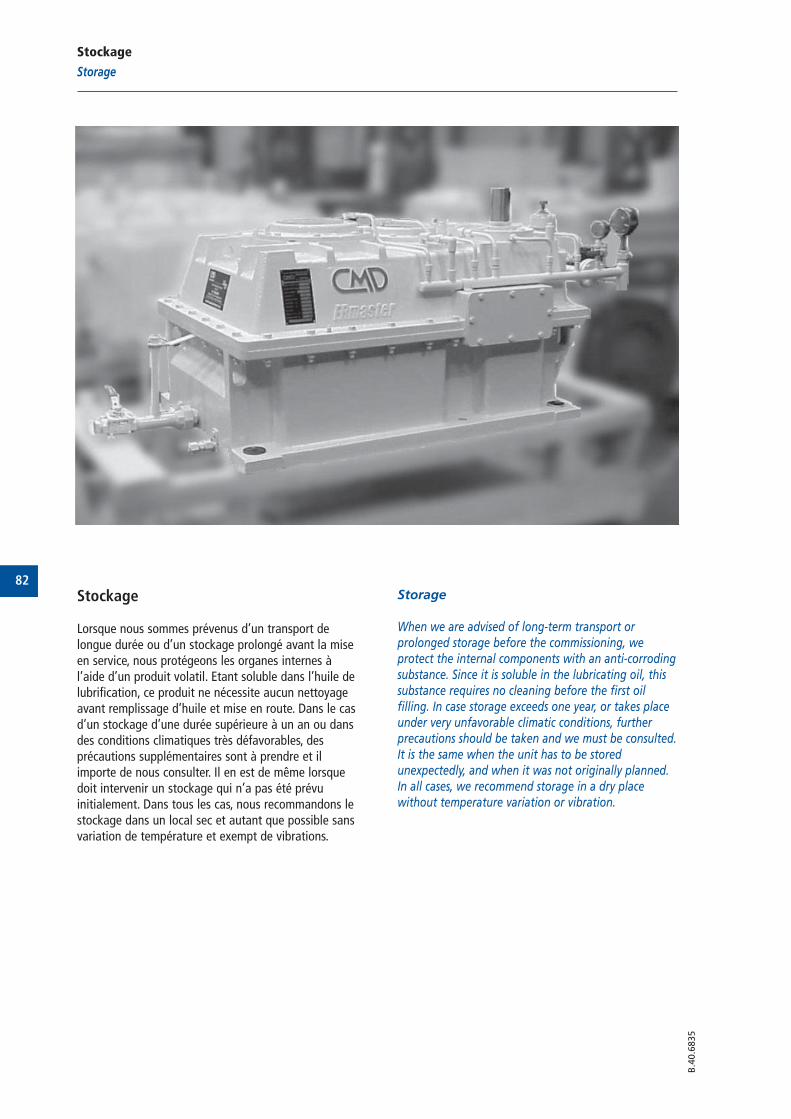
82
B.4
0.6
835
Stockage
Storage
Stockage
Lorsque nous sommes prévenus d’un transport delongue durée ou d’un stockage prolongé avant la miseen service, nous protégeons les organes internes àl’aide d’un produit volatil. Etant soluble dans l’huile delubrification, ce produit ne nécessite aucun nettoyageavant remplissage d’huile et mise en route. Dans le casd’un stockage d’une durée supérieure à un an ou dansdes conditions climatiques très défavorables, desprécautions supplémentaires sont à prendre et ilimporte de nous consulter. Il en est de même lorsquedoit intervenir un stockage qui n’a pas été prévuinitialement. Dans tous les cas, nous recommandons lestockage dans un local sec et autant que possible sansvariation de température et exempt de vibrations.
Storage
When we are advised of long-term transport orprolonged storage before the commissioning, weprotect the internal components with an anti-corrodingsubstance. Since it is soluble in the lubricating oil, thissubstance requires no cleaning before the first oilfilling. In case storage exceeds one year, or takes placeunder very unfavorable climatic conditions, furtherprecautions should be taken and we must be consulted.It is the same when the unit has to be storedunexpectedly, and when it was not originally planned.In all cases, we recommend storage in a dry placewithout temperature variation or vibration.
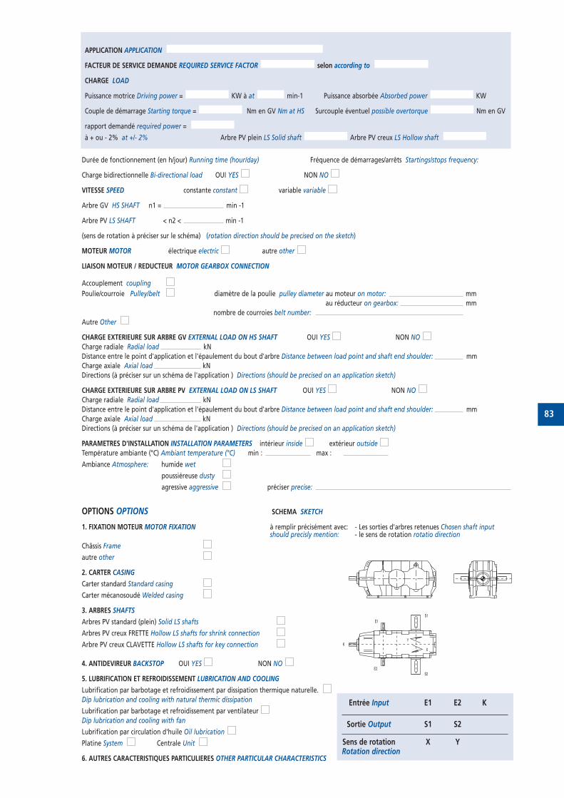
83
Durée de fonctionnement (en h/jour) Running time (hour/day) Fréquence de démarrages/arrêts Startings/stops frequency:
Charge bidirectionnelle Bi-directional load OUI YES NON NO
VITESSE SPEED constante constant variable variable
Arbre GV HS SHAFT n1 = min -1
Arbre PV LS SHAFT < n2 < min -1
(sens de rotation à préciser sur le schéma) (rotation direction should be precised on the sketch)
MOTEUR MOTOR électrique electric autre other
LIAISON MOTEUR / REDUCTEUR MOTOR GEARBOX CONNECTION
Accouplement coupling
Poulie/courroie Pulley/belt diamètre de la poulie pulley diameter au moteur on motor: mm
au réducteur on gearbox: mm
nombre de courroies belt number:
Autre Other
CHARGE EXTERIEURE SUR ARBRE GV EXTERNAL LOAD ON HS SHAFT OUI YES NON NO
Charge radiale Radial load kN
Distance entre le point d'application et l'épaulement du bout d'arbre Distance between load point and shaft end shoulder: mm
Charge axiale Axial load kN
Directions (à préciser sur un schéma de l'application ) Directions (should be precised on an application sketch)
CHARGE EXTERIEURE SUR ARBRE PV EXTERNAL LOAD ON LS SHAFT OUI YES NON NO
Charge radiale Radial load kN
Distance entre le point d'application et l'épaulement du bout d'arbre Distance between load point and shaft end shoulder: mm
Charge axiale Axial load kN
Directions (à préciser sur un schéma de l'application ) Directions (should be precised on an application sketch)
PARAMETRES D'INSTALLATION INSTALLATION PARAMETERS intérieur inside extérieur outside
Température ambiante (°C) Ambiant temperature (°C) min : max :
Ambiance Atmosphere: humide wet
poussiéreuse dusty
agressive aggressive préciser precise:
OPTIONS OPTIONS SCHEMA SKETCH
1. FIXATION MOTEUR MOTOR FIXATION à remplir précisément avec: - Les sorties d'arbres retenues Chosen shaft inputshould precisly mention: - le sens de rotation rotatio direction
Châssis Frame
autre other
2. CARTER CASING
Carter standard Standard casing
Carter mécanosoudé Welded casing
3. ARBRES SHAFTS
Arbres PV standard (plein) Solid LS shafts
Arbres PV creux FRETTE Hollow LS shafts for shrink connection
Arbre PV creux CLAVETTE Hollow LS shafts for key connection
4. ANTIDEVIREUR BACKSTOP OUI YES NON NO
5. LUBRIFICATION ET REFROIDISSEMENT LUBRICATION AND COOLING
Lubrification par barbotage et refroidissement par dissipation thermique naturelle.
Dip lubrication and cooling with natural thermic dissipation
Lubrification par barbotage et refroidissement par ventilateur
Dip lubrication and cooling with fan
Lubrification par circulation d'huile Oil lubrication
Platine System Centrale Unit
6. AUTRES CARACTERISTIQUES PARTICULIERES OTHER PARTICULAR CHARACTERISTICS
APPLICATION APPLICATION
FACTEUR DE SERVICE DEMANDE REQUIRED SERVICE FACTOR selon according to
CHARGE LOAD
Puissance motrice Driving power = KW à at min-1 Puissance absorbée Absorbed power KW
Couple de démarrage Starting torque = Nm en GV Nm at HS Surcouple éventuel possible overtorque Nm en GV
rapport demandé required power =
à + ou - 2% at +/- 2% Arbre PV plein LS Solid shaft Arbre PV creux LS Hollow shaft
Entrée Input E1 E2 K
Sortie Output S1 S2
Sens de rotation X Y Rotation direction
X
Y
E1
E2
S1
S2
K
USINES / FACTORIES
CMD CAMBRAI539, avenue du Cateau
59400 CAMBRAI - France
Tél : +33 (0) 3 27 73 53 11Fax : +33 (0) 3 27 78 36 99
CMD FOURCHAMBAULT33, rue du 4 septembre
58600 FOURCHAMBAULT
France
Tél : +33 (0) 3 86 60 38 00Fax : +33 (0) 3 86 60 38 38
SIÈGE SOCIAL / HEAD OFFICE
539, avenue du Cateau
59400 CAMBRAI France
Tél : +33 (0) 3 27 73 53 11Fax : +33 (0) 3 27 78 36 99www.cmdgears.com
DIRECTION SALES
COMMERCIALE DEPARTMENT
36, avenue de l’Europe
BP 43
78142 VELIZY France
Tél : +33 (0) 1 34 63 12 24 Fax : +33 (0) 1 34 63 12 12
E-mail : [email protected]
/