Embed Size (px)
Citation preview
1
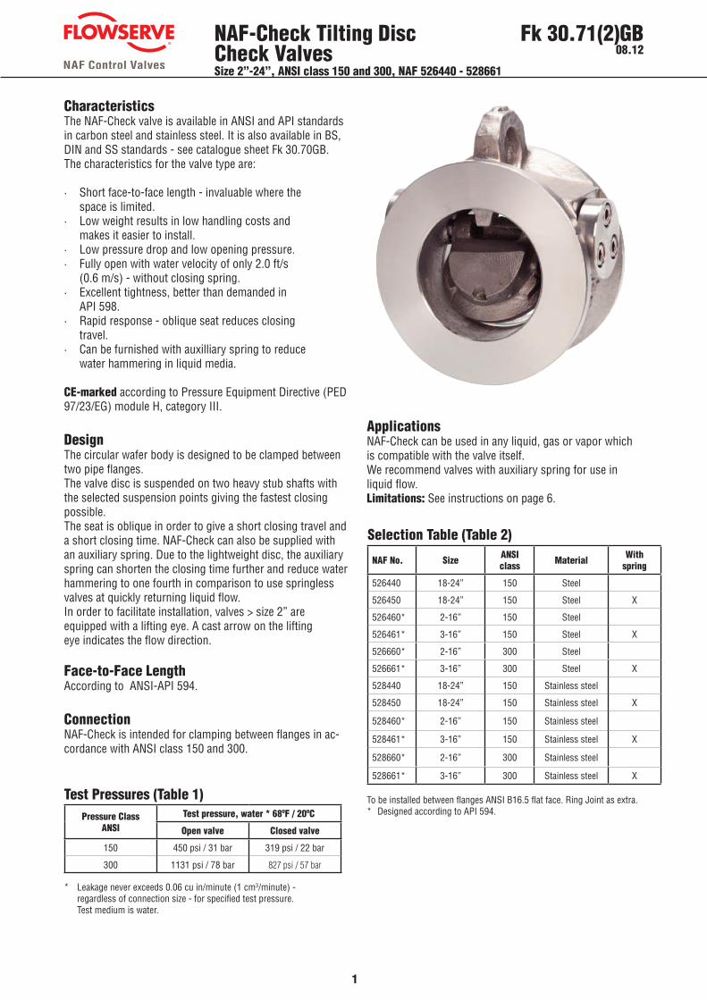
NAF-Check Tilting Disc Check ValvesSize 2”-24”, ANSI class 150 and 300, NAF 526440 - 528661
Fk 30.71(2)GB08.12
CharacteristicsThe NAF-Check valve is available in ANSI and API standards in carbon steel and stainless steel. It is also available in BS, DIN and SS standards - see catalogue sheet Fk 30.70GB. The characteristics for the valve type are:
· Short face-to-face length - invaluable where the space is limited. · Low weight results in low handling costs and makes it easier to install.· Low pressure drop and low opening pressure.· Fully open with water velocity of only 2.0 ft/s (0.6 m/s) - without closing spring.· Excellent tightness, better than demanded in API 598.· Rapid response - oblique seat reduces closing travel.· Can be furnished with auxilliary spring to reduce water hammering in liquid media.
CE-marked according to Pressure Equipment Directive (PED 97/23/EG) module H, category III.
DesignThe circular wafer body is designed to be clamped between two pipe flanges. The valve disc is suspended on two heavy stub shafts with the selected suspension points giving the fastest closing possible. The seat is oblique in order to give a short closing travel and a short closing time. NAF-Check can also be supplied with an auxiliary spring. Due to the lightweight disc, the auxiliary spring can shorten the closing time further and reduce water hammering to one fourth in comparison to use springless valves at quickly returning liquid flow.In order to facilitate installation, valves > size 2” are equipped with a lifting eye. A cast arrow on the lifting eye indicates the flow direction.
Face-to-Face LengthAccording to ANSI-API 594.
ConnectionNAF-Check is intended for clamping between flanges in ac-cordance with ANSI class 150 and 300.
ApplicationsNAF-Check can be used in any liquid, gas or vapor which is compatible with the valve itself.We recommend valves with auxiliary spring for use in liquid flow.Limitations: See instructions on page 6.
* Leakage never exceeds 0.06 cu in/minute (1 cm3/minute) - regardless of connection size - for specified test pressure. Test medium is water.
Test Pressures (Table 1)
Selection Table (Table 2)
To be installed between flanges ANSI B16.5 flat face. Ring Joint as extra.* Designed according to API 594.
NAF No. Size ANSI class Material With
spring
526440 18-24” 150 Steel
526450 18-24” 150 Steel X
526460* 2-16” 150 Steel
526461* 3-16” 150 Steel X
526660* 2-16” 300 Steel
526661* 3-16” 300 Steel X
528440 18-24” 150 Stainless steel
528450 18-24” 150 Stainless steel X
528460* 2-16” 150 Stainless steel
528461* 3-16” 150 Stainless steel X
528660* 2-16” 300 Stainless steel
528661* 3-16” 300 Stainless steel X
Pressure Class ANSI
Test pressure, water * 68ºF / 20ºC
Open valve Closed valve
150 450 psi / 31 bar 319 psi / 22 bar
300 1131 psi / 78 bar 827 psi / 57 bar
2
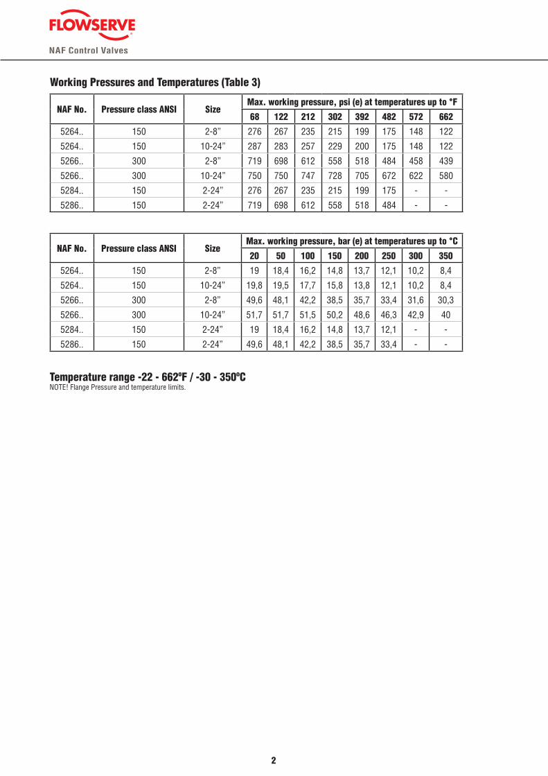
Working Pressures and Temperatures (Table 3)
Temperature range -22 - 662ºF / -30 - 350ºCNOTE! Flange Pressure and temperature limits.
NAF No. Pressure class ANSI SizeMax. working pressure, psi (e) at temperatures up to °F
68 122 212 302 392 482 572 662
5264.. 150 2-8” 276 267 235 215 199 175 148 122
5264.. 150 10-24” 287 283 257 229 200 175 148 122
5266.. 300 2-8” 719 698 612 558 518 484 458 439
5266.. 300 10-24” 750 750 747 728 705 672 622 580
5284.. 150 2-24” 276 267 235 215 199 175 - -
5286.. 150 2-24” 719 698 612 558 518 484 - -
NAF No. Pressure class ANSI SizeMax. working pressure, bar (e) at temperatures up to °C
20 50 100 150 200 250 300 350
5264.. 150 2-8” 19 18,4 16,2 14,8 13,7 12,1 10,2 8,4
5264.. 150 10-24” 19,8 19,5 17,7 15,8 13,8 12,1 10,2 8,4
5266.. 300 2-8” 49,6 48,1 42,2 38,5 35,7 33,4 31,6 30,3
5266.. 300 10-24” 51,7 51,7 51,5 50,2 48,6 46,3 42,9 40
5284.. 150 2-24” 19 18,4 16,2 14,8 13,7 12,1 - -
5286.. 150 2-24” 49,6 48,1 42,2 38,5 35,7 33,4 - -
3
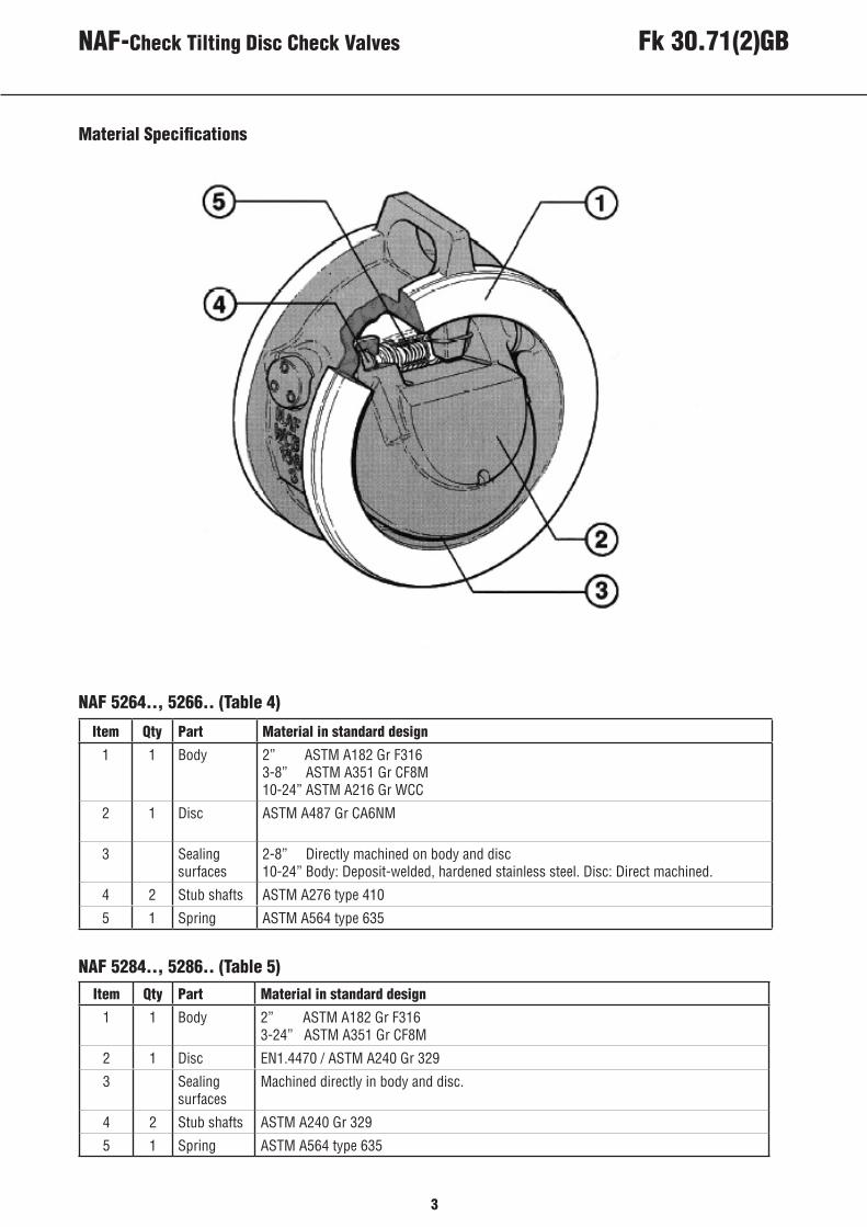
Material Specifications
NAF-Check Tilting Disc Check Valves
NAF 5264.., 5266.. (Table 4)
NAF 5284.., 5286.. (Table 5)
Item Qty Part Material in standard design
1 1 Body 2” ASTM A182 Gr F3163-8” ASTM A351 Gr CF8M 10-24” ASTM A216 Gr WCC
2 1 Disc ASTM A487 Gr CA6NM
3 Sealing surfaces
2-8” Directly machined on body and disc10-24” Body: Deposit-welded, hardened stainless steel. Disc: Direct machined.
4 2 Stub shafts ASTM A276 type 410
5 1 Spring ASTM A564 type 635
Item Qty Part Material in standard design
1 1 Body 2” ASTM A182 Gr F3163-24” ASTM A351 Gr CF8M
2 1 Disc EN1.4470 / ASTM A240 Gr 329
3 Sealing surfaces
Machined directly in body and disc.
4 2 Stub shafts ASTM A240 Gr 329
5 1 Spring ASTM A564 type 635
Fk 30.71(2)GB
4
Selection of Valve Size and Pressure DropIn pipes with steam or gases (compressible media) it is important to check that the valve is fully open and the disc is pressed against the stop at all normal operating conditions. This in order to avoid disc flutter giving noise and shorter valve life.
The dynamic opening force on the disc depends on the density of the medium and the flow velocity in the pipe. Use the diagram 1 for vertical pipe and diagram 2 for hori-zontal pipe. Set the value of ρxv2 on the horizontal axis and check the curves.Depending on installation position, the valve without auxiliary spring is fully open if the value ρxv2 on the horizontal axis is larger than 300 in a vertical pipe, or 650 in a horizontal pipe. Select a smaller size if the valve is not fully open
Valves with auxiliary spring, which we only recommend for use in liquids - at the risk of water hammering - the corresponding values are 700 and 1300. Read the pressure drop across fully open valve on the vertical axis and at the intersection of the straight line ”Fully open valve”. The pressure drop is larger if the valve is not fully open (follow resp. line regarding pipe and spring).
The curves in diagram 1 and 2 represent sizes up to size 4”. The pressure drop is lower for larger sizes. Reduce the diagram pressure drop values with the following factors:
Sizes 6-10” factor 0.72Sizes 12-18” factor 0.62Sizes 20-24” factor 0.38
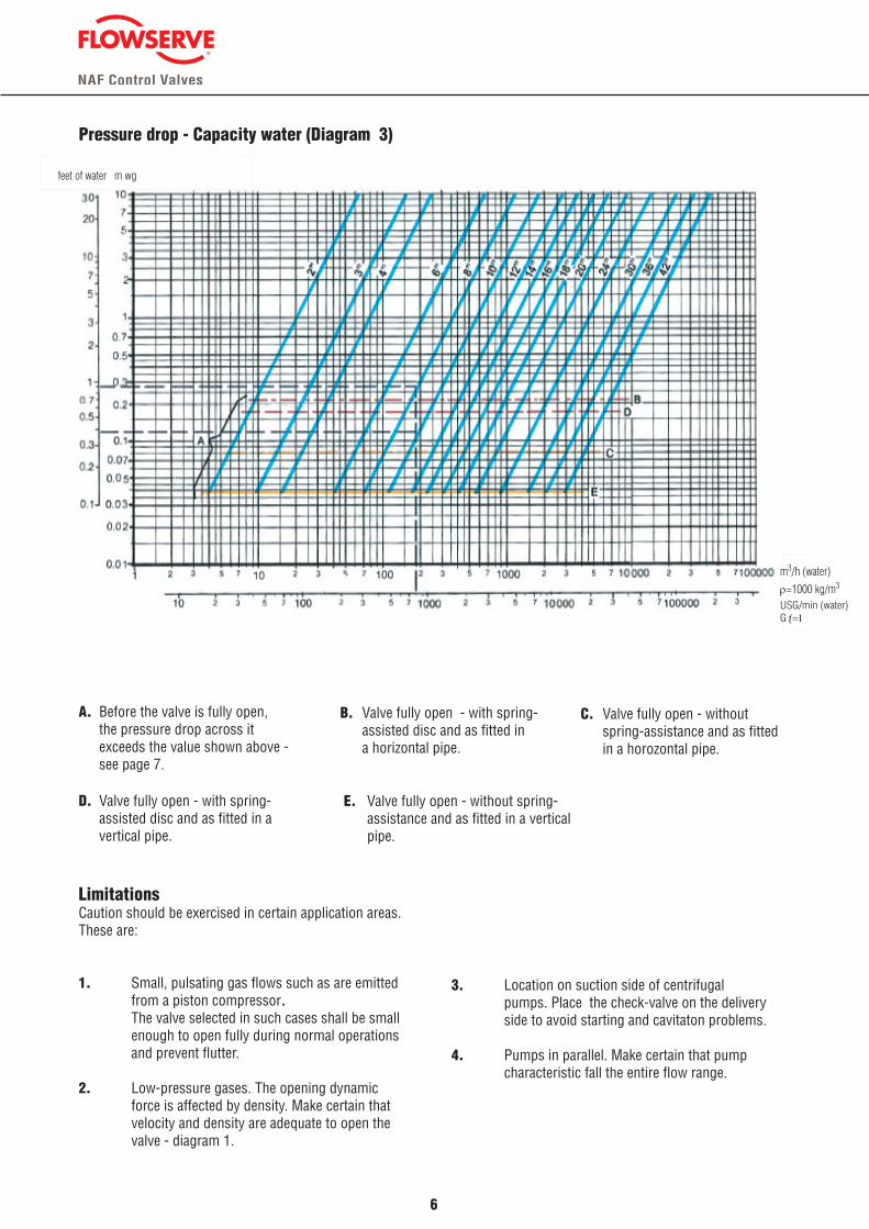
With flow rate - in water - known in m3/h or USG/min the pressure drop across the valve can be read directly in diagram 3.
5
NAF-Check Tilting Disc Check Valves Fk 30.71(2)GB
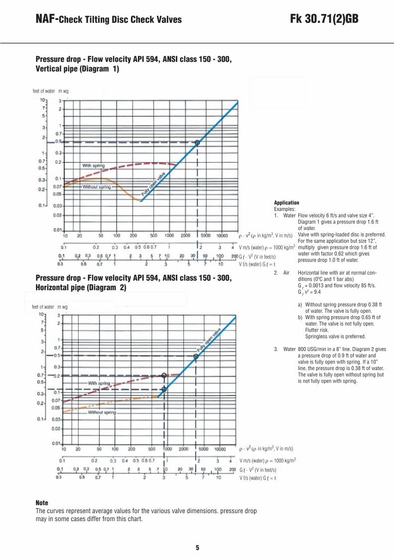
NoteThe curves represent average values for the various valve dimensions. pressure drop may in some cases differ from this chart.
Pressure drop - Flow velocity API 594, ANSI class 150 - 300, Vertical pipe (Diagram 1)
Pressure drop - Flow velocity API 594, ANSI class 150 - 300, Horizontal pipe (Diagram 2)
ρ ⋅ v2 (ρ in kg/m3, V in m/s)
V m/s (water) ρ = 1000 kg/m3
Gƒ ⋅ V2 (V in feet/s)V f/s (water) Gƒ = 1
feet of water m wg
ρ ⋅ v2 (ρ in kg/m3, V in m/s)
V m/s (water) ρ = 1000 kg/m3
Gƒ ⋅ V2 (V in feet/s)V f/s (water) Gƒ = 1
feet of water m wg
ApplicationExamples: 1. Water Flow velocity 6 ft/s and valve size 4”. Diagram 1 gives a pressure drop 1.6 ft of water. Valve with spring-loaded disc is preferred. For the same application but size 12”, multiply given pressure drop 1.6 ft of water with factor 0.62 which gives pressure drop 1.0 ft of water.
2. Air Horizontal line with air at normal con- ditions (0ºC and 1 bar abs) G ƒ = 0.0013 and flow velocity 85 ft/s. G ƒ v
2 = 9.4
a) Without spring pressure drop 0.38 ft of water. The valve is fully open. b) With spring pressure drop 0.65 ft of water. The valve is not fully open. Flutter risk. Springless valve is preferred.
3. Water 800 USG/min in a 8” line. Diagram 2 gives a pressure drop of 0.9 ft of water and valve is fully open with spring. If a 10” line, the pressure drop is 0.38 ft of water. The valve is fully open without spring but is not fully open with spring.
6
C. Valve fully open - without spring-assistance and as fitted in a horozontal pipe.
B. Valve fully open - with spring- assisted disc and as fitted in a horizontal pipe.
A. Before the valve is fully open, the pressure drop across it exceeds the value shown above - see page 7.
E. Valve fully open - without spring- assistance and as fitted in a vertical pipe.
D. Valve fully open - with spring- assisted disc and as fitted in a vertical pipe.
3. Location on suction side of centrifugal pumps. Place the check-valve on the delivery side to avoid starting and cavitaton problems.
4. Pumps in parallel. Make certain that pump characteristic fall the entire flow range.
LimitationsCaution should be exercised in certain application areas. These are:
1. Small, pulsating gas flows such as are emitted from a piston compressor. The valve selected in such cases shall be small enough to open fully during normal operations and prevent flutter.
2. Low-pressure gases. The opening dynamic force is affected by density. Make certain that velocity and density are adequate to open the valve - diagram 1.
Pressure drop - Capacity water (Diagram 3)
feet of water m wg
m3/h (water)ρ=1000 kg/m3
USG/min (water)Gƒ=1
7
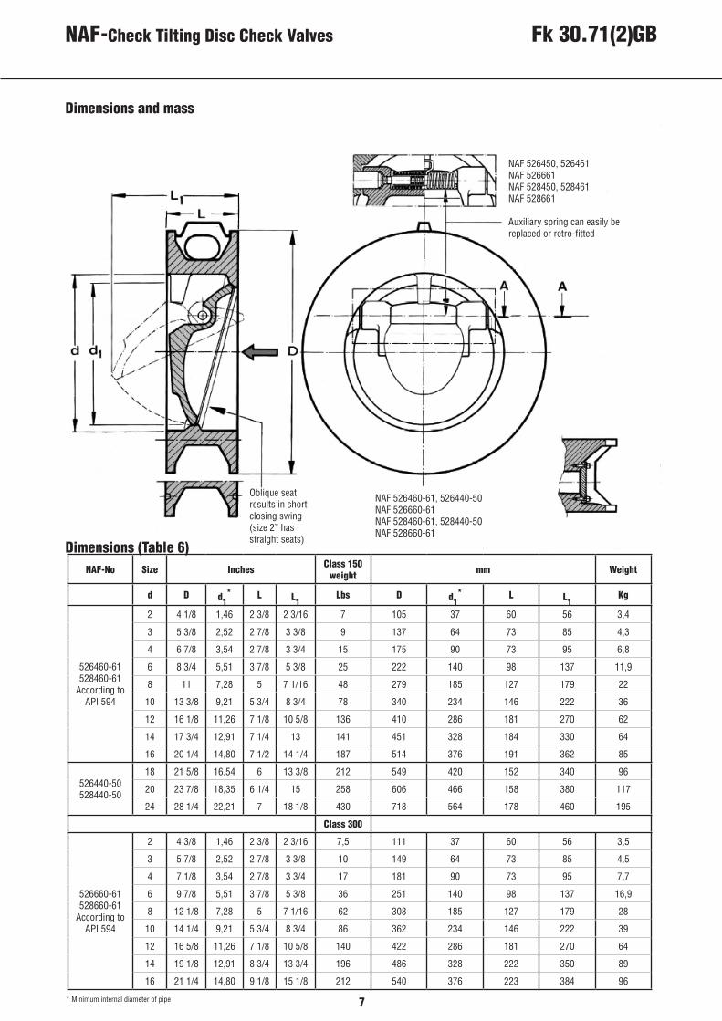
NAF 526450, 526461 NAF 526661NAF 528450, 528461NAF 528661
Auxiliary spring can easily bereplaced or retro-fitted
NAF 526460-61, 526440-50NAF 526660-61NAF 528460-61, 528440-50NAF 528660-61
Oblique seat results in short closing swing(size 2” has straight seats)
* Minimum internal diameter of pipe
Dimensions and mass
Dimensions (Table 6) NAF-No Size Inches Class 150
weight mm Weight
d D d1* L L1
Lbs D d1* L L1
Kg
526460-61528460-61
According toAPI 594
2 4 1/8 1,46 2 3/8 2 3/16 7 105 37 60 56 3,4
3 5 3/8 2,52 2 7/8 3 3/8 9 137 64 73 85 4,3
4 6 7/8 3,54 2 7/8 3 3/4 15 175 90 73 95 6,8
6 8 3/4 5,51 3 7/8 5 3/8 25 222 140 98 137 11,9
8 11 7,28 5 7 1/16 48 279 185 127 179 22
10 13 3/8 9,21 5 3/4 8 3/4 78 340 234 146 222 36
12 16 1/8 11,26 7 1/8 10 5/8 136 410 286 181 270 62
14 17 3/4 12,91 7 1/4 13 141 451 328 184 330 64
16 20 1/4 14,80 7 1/2 14 1/4 187 514 376 191 362 85
526440-50528440-50
18 21 5/8 16,54 6 13 3/8 212 549 420 152 340 96
20 23 7/8 18,35 6 1/4 15 258 606 466 158 380 117
24 28 1/4 22,21 7 18 1/8 430 718 564 178 460 195
Class 300
526660-61528660-61
According to API 594
2 4 3/8 1,46 2 3/8 2 3/16 7,5 111 37 60 56 3,5
3 5 7/8 2,52 2 7/8 3 3/8 10 149 64 73 85 4,5
4 7 1/8 3,54 2 7/8 3 3/4 17 181 90 73 95 7,7
6 9 7/8 5,51 3 7/8 5 3/8 36 251 140 98 137 16,9
8 12 1/8 7,28 5 7 1/16 62 308 185 127 179 28
10 14 1/4 9,21 5 3/4 8 3/4 86 362 234 146 222 39
12 16 5/8 11,26 7 1/8 10 5/8 140 422 286 181 270 64
14 19 1/8 12,91 8 3/4 13 3/4 196 486 328 222 350 89
16 21 1/4 14,80 9 1/8 15 1/8 212 540 376 223 384 96
NAF-Check Tilting Disc Check Valves Fk 30.71(2)GB
Pressure drop - Capacity water (Diagram 3)
feet of water m wg
m3/h (water)ρ=1000 kg/m3
USG/min (water)Gƒ=1
8
NAF AB SE-581 87 LinköpingSweden
Telephone +46 13 31 61 00 Facsimile +46 13 13 60 54 e-mail [email protected]: www.naf.se
We reserve the right to design mo-difications without prior notice
ISO 9001 Certified
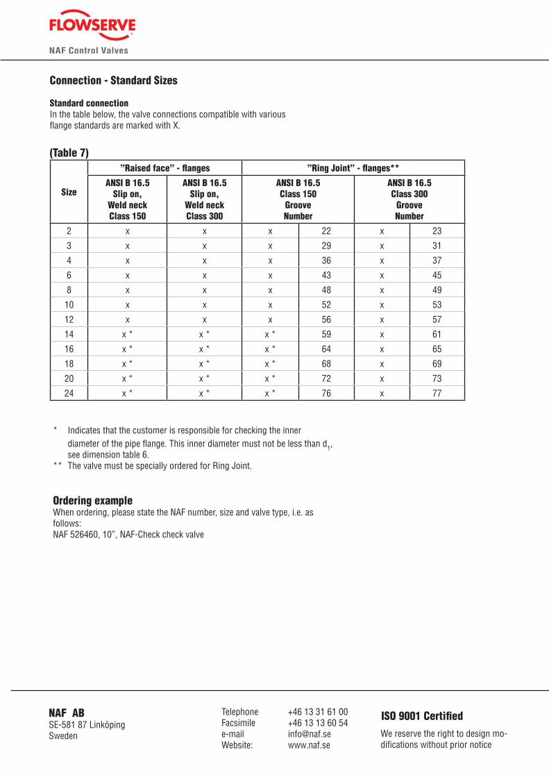
Connection - Standard Sizes
Standard connectionIn the table below, the valve connections compatible with various flange standards are marked with X.
(Table 7)
Size
”Raised face” - flanges ”Ring Joint” - flanges**
ANSI B 16.5Slip on,
Weld neckClass 150
ANSI B 16.5Slip on,
Weld neckClass 300
ANSI B 16.5Class 150
GrooveNumber
ANSI B 16.5Class 300
GrooveNumber
2 x x x 22 x 23
3 x x x 29 x 31
4 x x x 36 x 37
6 x x x 43 x 45
8 x x x 48 x 49
10 x x x 52 x 53
12 x x x 56 x 57
14 x * x * x * 59 x 61
16 x * x * x * 64 x 65
18 x * x * x * 68 x 69
20 x * x * x * 72 x 73
24 x * x * x * 76 x 77
* Indicates that the customer is responsible for checking the inner diameter of the pipe flange. This inner diameter must not be less than d1, see dimension table 6.** The valve must be specially ordered for Ring Joint.
Ordering exampleWhen ordering, please state the NAF number, size and valve type, i.e. as follows:NAF 526460, 10”, NAF-Check check valve