1
SS SS FFL 144.440 Ex 143.97+ Ex 143.84+ Ex 143.83+ Ex 143.86+ 143.87+ 143.95+ 144.04+ 144.10+ Ex 144.37+ Ex 144.02+ Apx 144.02+ Ex 144.08+ Ex 144.11+ Ex 144.17+ Ex 144.09+ +144.78 Ex +144.70 Ex +145.59 Apx +145.36 Ex +145.84 Ex +143.870 FFL 145.365 FFL 145.140 FFL 145.625 FFL 144.765 FFL 145.515 FFL 145.215 FFL 144.990 FFL 144.440 FFL 144.440 FFL 144.440 FFL 144.440 FFL 144.800 145.06+ +145.26 Apx 145.44+ +145.69 +145.87 +145.96 Ex FFL 144.440 FFL 144.440 FFL 145.310 FFL 145.610 FFL 145.835 +LJKZD\ Drain 1:13 > +LJKZD\ 'UDLQ +144.30 144.16+ +144.11 Apx Ex 144.05+ +144.04 Apx 144.02+ Ex 144.25+ +144.07 +144.09 144.12+ 144.74+ +144.96 Apx FFL 145.140 6 Highway Drain CL 145.650 IL 144.225 6 Highway Drain CL 145.575 IL 144.150 RG RG RG RG RG RG RG RG RG RG RG RG RG FFL 145.100 RF 225 Existing RF Existing RF Existing RF RF 225 RF 450 RF 300 RF 300 RF 225 RF 225 - - - - - T T T T T T T - - - - - - - - - - - - - - - - RF 225 RF 250 RF 050 RF 050 RF 050 RF 300 RF 050 RG RG RG +144.43 144.43+ +144.53 144.53+ 1:15> +144.25 144.25+ +144.15 144.15+ <1:15 +144.27 144.27+ +144.37 144.37+ 1:15> +144.40 +144.30 144.30+ <1:15 +144.445 144.475+ RG +144.540 RG RG 144.465+ 144.535+ 144.605+ 144.390+ 144.435+ +144.480 RF 150 144.650 / / / / / / / / / / / RG RG RG +144.20 6000 37050 6000 6000 6000 6000 2000 2000 2000 2000 R10000 R16000 R6000 R6000 R2500 R2500 2000 2000 2000 2000 2000 7275 7600 8550 2000 2000 4800 2000 6000 1500 1500 1500 6800 300 2000 7200 2000 1965 1500 1500 5300 2000 1650 975 1650 575 575 6225 975 CAPPING THICKNESS (mm) SUB-BASE THICKNESS (mm) Capping/Sub- base design FIGURE 3.1 Capping and Sub-base Thickness Design Volume 7 section 2 part 2 HD25/94 Pavement design and construction - foundations Subgrade CBR (%) Sub-base only Design for flexible and flexible composite pavements, capping not required SUB-BASE Key:- Capping and Sub-base Thickness Design The thickness of sub-base and capping shall be obtained from Figure 3.1. The sub-base may be omitted where the CBR is above 30%. Where the sub grade CBR is greater than 15%, the thickness of sub-base required is 150mm. When the sub grade CBR is between 2.5% and 15% for flexible and flexible composite construction, there are two options available. 1. 150mm of sub-base can be used over a varying thickness of capping which depends on the CBR value. 2. An increasing thickness of sub-base shall be used with the decreasing CBR, with no requirement for capping. For all pavements and sub grades with CBR values below 2.5%, 150mm of sub-base on the varying thickness of capping must be used. When the sub grade CBR is below 2% even after proof rolling, seek the advice of the engineer. The design should be based on the lowest CBR value and not amended unless there is significant increase in the CBR along the road. Soils liable to frost heave should have at least 450 mm of construction cover. Sub-Base - 100mm Type 1 Granular sub-base material "Specification for Highway Works" - Clause 803 see table Surface Course - 30mm AC10 close Surf 100/150. To BS.EN.13018-1 Vehicle Crossing Construction Base - 150 mm Coated Macadam Basecourse Binder course - 60 mm compacted Dense Bitumen Macadam 20 mm nominal size aggregate 125 pen binder, Clause 906 (DTp) BS 4987 Part 1 2001 Clause 6.5 Surface course - 40 mm Stone Mastic Asphalt Sub-base - not less than 150mm of Type 1 Granular material in accordance with Clause 803 (DTp), thickness to be obtained from CBR Table. Road Construction NOTES 1. Soils liable to frost heave should have at least 450 mm of construction cover. 2. For soils having a CBR values less than 2%, the advice of the engineer must be sought. Note: Use Terram Weed Guard or Alternative Spray Type 1 with suitable Herbicide Tie in to Existing Carriageway. New Construction Existing Construction Binder Course Base Sub-base Surface Course All horizontal surfaces to be tack coated (K170) 300min 300 min Sub-Base - 100mm Type 1 Granular sub-base material "Specification for Highway Works" - Clause 803 Surface Course - 30mm of AC6 dense surf 100/150. To BS.EN.13018-1 Footway Construction Vertical joint sealed with hot poured bitumen 300 min Sub-base benched at 150mm intervals Capping layer - 6F2. Required thickness to be determined by the CBR value and chart (Fig 3.1 below) Base - 170 mm compacted Dense Bitumen Macadam laid in 2 layers, 32mm nominal size aggregate to BS:4987 Clause 5.1 Binder course - 50mm AC 20 dense bin 100/150 To EN.13108-1 Binder Course Surface Course Base Course Sub-base Additional Base Course 100 mm 25 125 1500 25mm kerb face 125mm kerb face 1:15 Camber Lay regulating binder course, binder course x 60mm, and surface course. Cut vertical joints top and bottom of ramp Create 1.5m long ramp between vertical joints with binder course and wearing course material. Coloured surface to table top to be agreed with CC Engineer. Adjacent Footway to be a Vehicle Crossing Construction Specification. Raised Table Ramp Construction Also to be used adjacent to raised-tables 1. Permitted alternative materials:- i. Precast concrete to BS 5911. ii. Vitrified clay to BS 539 iii. C20P insitu concrete 150mm thickness extending to the sides of the excavation with a polypropylene or similar permanent integral shutter. 2. Gratings supplied in separate sections shall be loosely coupled by means of bolts or other coupling devices in accordance with EN 124: 1994. 3. Method of Construction:- i. Gully pot to be placed in position with temporary cover. ii. All pavement courses excluding wearing course to be laid. iii. Pavement to be excavated not exceeding 200 beyond sides of gully to allow grating and frame to be fixed. iv. Excavation to be backfilled with Class C20P concrete to underside of binder course. 150mm thk Grade ST2 concrete surround (vibrated) 450x900dp Pre Cast Concrete Gully Class 'B' engineering brickwork in Class 1 Mortar CL 2402. Min 2<Max 3 courses of brickwork cobbled to fully support frame and cover PP FRQQHFWLRQ within 150mm concrete bedding surround Road Gully Grating to be placed 10mm below road surface D400 Grade A Class 1 ductile iron or cast iron gully grating and frame 450 nominal width. to BS.EN.124, Gully to have a captive hinged grid KDYLQJ D PLQLPXP ZDWHUZD\ DUHD RI FPò P0 Preliminary Issue 06.04.17 RM Drawing No. Drawn Date Scales Checked Client Status Drawing Project E. [email protected] United Kingdom W. www.patrickparsons.co.uk Rev. Birmingham 9 Frederick Road Edgbaston B15 1JD T. +44 (0)121 454 4413 Market Square Silver Court Brownhills S38 & S278 Hybrid Agreement Adoptable Highway Coloured Plan 1:250, 1:10 RM March 2017 RAA Approval / Comment B16303-230 P3 KEY +155.000 Proposed Levels FFL 155.00 Finished Floor Level S38 Shared Surface S38 Road Gully N S E W NE NW SW SE MAGNETIC NORTH Scale 1:250 2 0m 4 6 8 10 12 14 16 18 20 22 24 and S38 Carriageway S38 Highway Drain S278 Hybrid Works to Highway Land S104 / Public SWS A Street Lighting Design will be commissioned and will be added to drawings on completion. NOTE Preliminary scheme only for comment & review. Based upon information provided / available at the time. Scheme will be subject to full review and amendment as further information becomes available. Scheme will be subject to amendment following receipt of comments from the Development Control, LA Planning Authority, Environment Agency, LA Highways department and the Sewerage Undertaker. Following receipt of further information and comments the scheme may require a re-design. 1. Roads and footways to be adopted under Section 38 of Highways Act 1980 shall comply with the adopting Local Authority Highway Design Guidelines for New Developments and be in accordance with the Highways Agency Design Manual for Roads and Bridges. 2. All works within public highway to comply with current health and safety standards and all signing shall comply with Chapter 8 Traffic Safety measures and Signs for Roadworks and Temporary situations of the Traffic Signs Manual. 3. Design is subject to Building Regulation, Sewage Undertaker and Highways Department approval. 4. Before work commences contractor should consult the engineer and the SI report regarding any contamination issues. All necessary Health and Safety measures to be taken. 5. A Covenant will be provided to the benefit of the Local Authority ensuring that no planting or structure greater than 600mm in height to be permanently situated within the visibility splay 6. Rear of visibility splays to be delineated with a continuous 50 x 150 PC concrete Type EF square edging set at a level to enable the grass (if any) to be cut. 7. Boundary walls will not be adopted. 8. CBR values and calculations may be required to determine sub-base thickness. 9. Hand laying of bituminous materials is not permitted on adoptable carriageway 10. Tarmac road construction to comply with BS.EN.130108 11. All substrata structures and unconsolidated material, within the construction width of the highway, are to be removed 12. 150mm x 50mm back edging kerbs will be laid upturned and flush at footway crossovers. 13. Where two or more water services boundary boxes are situated together multi-meter boundary as specified by the Sewerage Undertaker are to be installed 14. Stopcock and Meter Covers shall not be located within the vehicular crossing construction 15. Hinged gully grate and frame to BS EN 124, grade D400, non-rocking with captive left hand end hinge. Minimum waterway area 900cm squared. Frame depth 100mm. Black coated ductile iron 16. All gully pots to BS5911 or BS 65 minimum size 900mm x 450mm 17. All trenches within the adoptable areas will be backfilled with Type 1, or materials specified in Clause 6.17 18. In drainage easement areas no buildings, walls or other structures and no planting of trees, shrubs or hedges and no private drains or manholes. 19. All existing drainage levels, diameters & locations need to be checked on site and any discrepancies need to be reported back to the Engineer. 20. Manhole covers and gully grates to be adopted shall be kitemarked and to BS EN124. Class D400, gully grates 450mm square. 21. Manholes located within turning areas of junction to have covers treated with an anti-slip coating. 22. Cover levels for manholes are approximate only and should be adjusted to match surrounding levels 23. In block paved areas 'Infill' type covers should not be used, and frames must be 150mm deep. 24. All adoptable pipe work for Highway drains to be minimum concrete Class WR %6 RU &ODVV FOD\ RU N1P FUXVKLQJ VWUHQJWK LI PP to BSEN295-1 and laid on Class S granular bed unless shown otherwise. 25. Where pipe work has less than 1.2m cover under roads and 0.9m cover under drives and gardens the pipes are to be surrounded with 150mm of Class ST4/C20 concrete with flexibility of joints maintained as stated in Clause 4.2.28 of the Water Services Association Guide. Any Concrete bed and surround to pipe work to be sulphate resisting cement. 26. The provision of a CCTV survey of any highway drainage, at the developers expense, is required prior to laying the wearing course. 27. All connections to highway drains must be made via factory made junctions. 28. All works to sewers/ manholes being offered for adoption or on existing public sewers should be in accordance with "Sewers for Adoption 6th Edition" and the Sewerage Undertakers recommendations. S278 Hybrid Works rebuilt as Footway Coverslab to S104 adoptable sewer Existing Bellmouth to be removed and rebuilt as footway/crossover. Stopping-up order Made. Obsolete road signs and columns are to be removed as required. Existing Bellmouth to be removed and rebuilt as footway/crossover. Stopping-up order made. Obsolete road signs and columns are to be removed as required. New bellmouth to shared surface with tactile crossing for entry to shared surface. Rumble-strip and Road Nameplate to be provided. 2No 225mm Highway Drains to serve proposed S38 road gullies. Extent of Adoption to join limits of adoption on the previous S38 agreement with reference TBC. Stopping up order completed on this area. Highway is to be removed in agreement with Walsall MBC Representatives. P1 Updates to S104 and SWS in adoptable carriageway to suit new layout. Updates following meeting with Lovell's and WMBC representatives. 27.06.17 RM 1.3. LOCATIONS OF ALL EXISTING SERVICES ON-SITE TO BE CONFIRMED & PROVIDED TO THE ENGINEER PRIOR TO COMMENCEMENT OF WORKS. 1.4. THIS DRAWING IS TO BE READ IN CONJUNCTION WITH ALL RELEVANT PATRICK PARSONS LTD DRAWINGS & SPECIFICATIONS. Revisions Rev. Amendments Date By GENERAL NOTES 1.1. THIS DRAWING IS COPYRIGHT AND SHOULD NOT BE REPRODUCED IN WHOLE OR PART WITHOUT THE WRITTEN CONSENT OF PATRICK PARSONS LTD. 1.2 DO NOT SCALE FROM THIS DRAWING. A0 At original size 2No Speed Cushions. Rosehill Highway's rubber speed cushions 2000x1650mm with a 975mm transverse gap. Polymer Cannon Bollard Red/White retroreflective Bollards socketed into Titan/Trief Kerb. Manchester style Cast-Iron or Polymer, 6No @5m centres with Red/White Retroreflective banding. CCTV Column to be relocated by WMBC Sub-contractors. 2No Lighting Columns to be removed or relocated. Works to be carried out by WMBC street-lighting partners AMEY. Road Gullies to be relocated Ex Gullies to be rebuilt. New Gullies to serve the new raised table at low-point. Ex Lighting Column is to be removed or relocated. Works to be carried out by WMBC street-lighting partners AMEY Tactile Paving Crossing 400x400x65 Buff Blister Rumble Strip Granite Sett Chamber will require cover to be rebuilt at the new road level for raised table. New Gullies to serve new road-table ramp. 1.5m Ramp to Raised Table 100mm rise @1:15 P2 Amended to comments received from Lovells 07-07-17. Rumble strip relocated. Trief kerb profile extended westwards. One bollard added. 11.07.17 RM P3 Amended to comments received from Walsall Highways 13-07-17. Rumble strip, cushion and raised table shape and spec amended; changes to surfacing specification and notes. 13.07.17 RM 3No Speed Cushions. Rosehill Highway's rubber speed cushions 2000x1650mm with a 575mm transverse gap. Tactile Paving crossing/ access to raised table is to be provided. Road Nameplate is required for Pier Street Tactile Paving crossing/ access to raised table is to be provided.

T T T T T T T - Walsall · 2021. 1. 25. · To BS.EN.13018-1 Footway Construction Vertical joint sealed with hot poured bitumen 300 min Sub-base benched at 150mm intervals Capping

  • Upload
    others

  • View
    3

  • Download
    0

Embed Size (px)

Citation preview

SSSS

FFL 144.440

Ex 143.97+

Ex 143.84+

Ex 143.83+

Ex 143.86+

143.87+

143.95+

144.04+

144.10+

Ex 144.37+

Ex 144.02+

Apx 144.02+

Ex 144.08+

Ex 144.11+

Ex 144.17+

Ex 144.09+

+144.78 Ex+144.70 Ex

+145.59 Apx

+145.36 Ex

+145.84 Ex

+143.870

FFL 145.365

FFL 145.140

FFL 145.625

FFL 144.765

FFL 145.515

FFL 145.215

FFL 144.990

FFL 144.440

FFL 144.440

FFL 144.440

FFL 144.440

FFL 144.800

145.06+

+145.26 Apx

145.44+

+145.69

+145.8

7

+145.96 Ex

FFL 144.440

FFL 144.440

FFL 145.310

FFL 145.610

FFL 145.835

225Ø Highway

Drain 1:13 >

< 225Ø Highway Drain 1:8

+144.30

144.16+

+144.11 Apx

Ex 144.05+

+14

4.04

Apx 144.02+

Ex 144.25+

+14

4.07

+144.09

144.12+ 144.74+

+144.96 Apx

FFL 145.140

S38 1200ØHighway DrainCL 145.650IL 144.225

S38 1200ØHighway DrainCL 145.575IL 144.150

RG

RG

RG

RG

RG

RG

RG

RG

RG

RG

RG

RG

RG

FFL 145.100

RF 225

Existing RF

Existing RF

Existing RF

RF 225

RF 450

RF 300

RF 300

RF 225

RF 225

- - -

- -

T T T T T T T

- - -

- - -

- - -

- - -

- - -

-

RF 225

RF 250

RF 050

RF 050

RF 050

RF 300

RF 050

RG

RG

RG

+144.43

144.43+

+144.53

144.53+

1:15>

+144.25

144.25+

+144.15

144.15+

<1:15

+14

4.27

144.

27+

+14

4.37

144.

37+

1:15>

+14

4.40

+14

4.30

144.

30+

<1:15

+144.445

144.475+

RG

+144.540

RG

RG

144.465+ 144.535+

144.605+

144.390+ 144.435+

+144.480

RF 15

0

144.

650

/ / /

/ / /

/ / /

/ /

RG

RG

RG

+144.20

6000

3705

0

6000

6000

6000

60002000

2000

2000

2000

R10000R16000

R60

00

R6000

R2500

R2500

2000

2000

2000

2000

2000

7275

7600

85502000

2000

4800

2000

6000

1500

1500

1500

6800

300

2000

7200

2000

1965

1500

1500

5300

2000

1650

975

1650

575

575

6225

975

CAPPINGTHICKNESS (mm)

SUB-BASETHICKNESS (mm)

Capping/Sub- base design

FIGURE 3.1 Capping and Sub-base Thickness Design Volume 7 section 2 part 2 HD25/94Pavement design and construction - foundations

Subgrade CBR (%)

Sub-base only Design forflexible and flexiblecomposite pavements,capping not required

SUB-BASE

Key:-

Capping and Sub-base Thickness Design

The thickness of sub-base and capping shall be obtained from Figure 3.1.The sub-base may be omitted where the CBR is above 30%.

Where the sub grade CBR is greater than 15%, the thickness of sub-base required is 150mm.When the sub grade CBR is between 2.5% and 15% for flexible and flexible composite construction, there aretwo options available.

1. 150mm of sub-base can be used over a varying thickness of capping which depends on the CBR value.2. An increasing thickness of sub-base shall be used with the decreasing CBR, with no requirement for capping.

For all pavements and sub grades with CBR values below 2.5%, 150mm of sub-base on the varying thickness ofcapping must be used.

When the sub grade CBR is below 2% even after proof rolling, seek the advice of the engineer.The design should be based on the lowest CBR value and not amended unless there is significant increase inthe CBR along the road.Soils liable to frost heave should have at least 450 mm of construction cover.

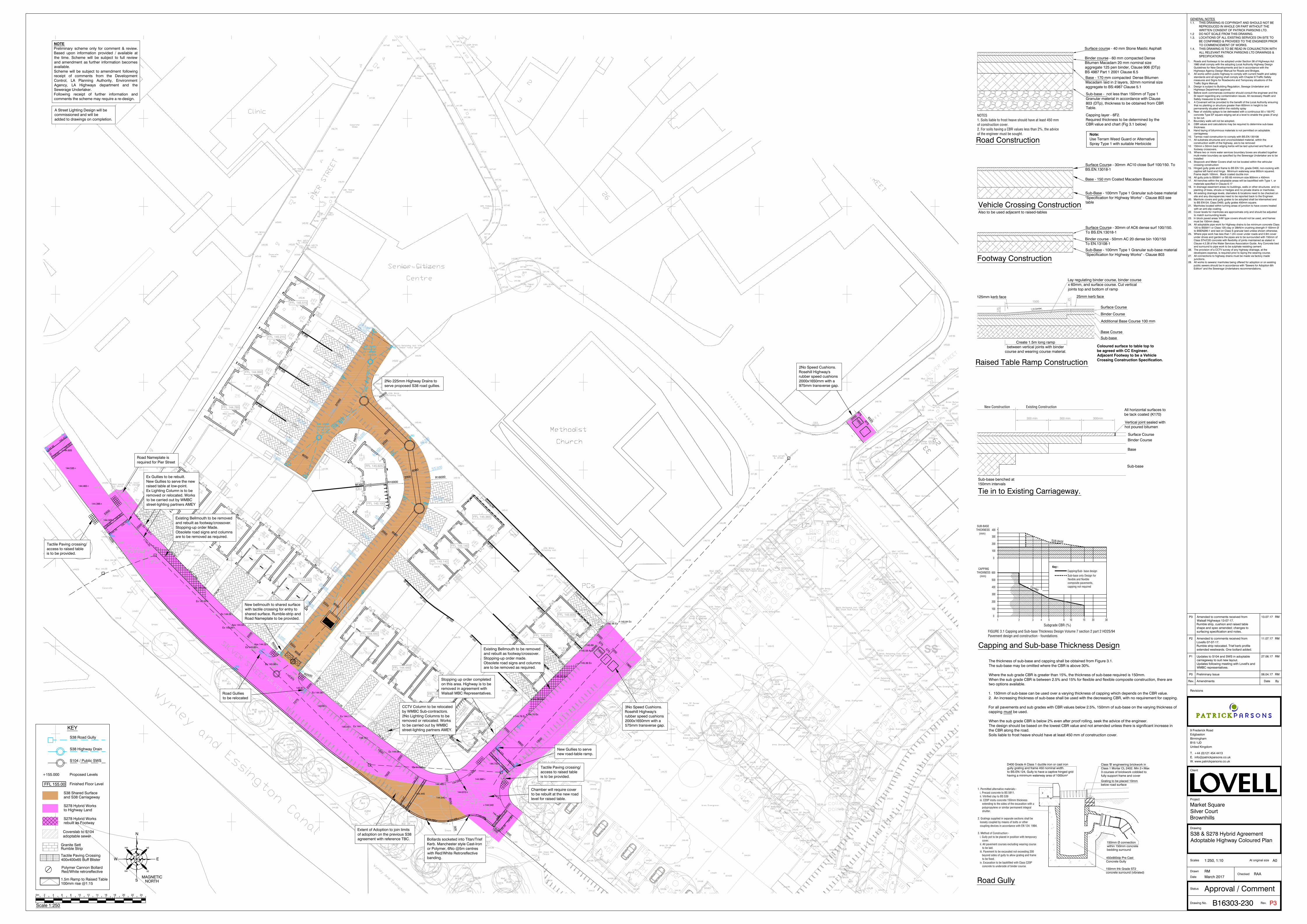
Sub-Base - 100mm Type 1 Granular sub-base material"Specification for Highway Works" - Clause 803 seetable

Surface Course - 30mm AC10 close Surf 100/150. ToBS.EN.13018-1

Vehicle Crossing Construction

Base - 150 mm Coated Macadam Basecourse

Binder course - 60 mm compacted DenseBitumen Macadam 20 mm nominal sizeaggregate 125 pen binder, Clause 906 (DTp)BS 4987 Part 1 2001 Clause 6.5

Surface course - 40 mm Stone Mastic Asphalt

Sub-base - not less than 150mm of Type 1Granular material in accordance with Clause803 (DTp), thickness to be obtained from CBRTable.

Road Construction

NOTES1. Soils liable to frost heave should have at least 450 mmof construction cover.2. For soils having a CBR values less than 2%, the adviceof the engineer must be sought. Note:

Use Terram Weed Guard or AlternativeSpray Type 1 with suitable Herbicide

Tie in to Existing Carriageway.

New Construction Existing Construction

Binder Course

Base

Sub-base

Surface Course

All horizontal surfaces tobe tack coated (K170)

300min300 min

Sub-Base - 100mm Type 1 Granular sub-base material"Specification for Highway Works" - Clause 803

Surface Course - 30mm of AC6 dense surf 100/150.To BS.EN.13018-1

Footway Construction

Vertical joint sealed withhot poured bitumen

300 min

Sub-base benched at150mm intervals

Capping layer - 6F2.Required thickness to be determined by theCBR value and chart (Fig 3.1 below)

Base - 170 mm compacted Dense BitumenMacadam laid in 2 layers, 32mm nominal sizeaggregate to BS:4987 Clause 5.1

Binder course - 50mm AC 20 dense bin 100/150To EN.13108-1

Binder Course

Surface Course

Base Course

Sub-base

Additional Base Course 100 mm

25

125

1500

25mm kerb face125mm kerb face

1:15 Camber

Lay regulating binder course, binder coursex 60mm, and surface course. Cut verticaljoints top and bottom of ramp

Create 1.5m long rampbetween vertical joints with binder

course and wearing course material.Coloured surface to table top tobe agreed with CC Engineer.Adjacent Footway to be a VehicleCrossing Construction Specification.Raised Table Ramp Construction

Also to be used adjacent to raised-tables

1. Permitted alternative materials:-i. Precast concrete to BS 5911.ii. Vitrified clay to BS 539iii. C20P insitu concrete 150mm thickness

extending to the sides of the excavation with apolypropylene or similar permanent integralshutter.

2. Gratings supplied in separate sections shall beloosely coupled by means of bolts or othercoupling devices in accordance with EN 124: 1994.

3. Method of Construction:-i. Gully pot to be placed in position with temporary

cover.ii. All pavement courses excluding wearing course

to be laid.iii. Pavement to be excavated not exceeding 200

beyond sides of gully to allow grating and frameto be fixed.

iv. Excavation to be backfilled with Class C20Pconcrete to underside of binder course.

150mm thk Grade ST2concrete surround (vibrated)

450x900dp Pre CastConcrete Gully

Class 'B' engineering brickwork inClass 1 Mortar CL 2402. Min 2<Max3 courses of brickwork cobbled tofully support frame and cover

150mm Ø connectionwithin 150mm concretebedding surround

Road Gully

Grating to be placed 10mmbelow road surface

D400 Grade A Class 1 ductile iron or cast irongully grating and frame 450 nominal width.to BS.EN.124, Gully to have a captive hinged gridhaving a minimum waterway area of 1000cm²

P0 Preliminary Issue 06.04.17 RM

Drawing No.

Drawn

Date

Scales

Checked

Client

Status

Drawing

Project

E. [email protected]

United Kingdom

W. www.patrickparsons.co.uk

Rev.

Birmingham

9 Frederick RoadEdgbaston

B15 1JD

T. +44 (0)121 454 4413

Market SquareSilver CourtBrownhills

S38 & S278 Hybrid AgreementAdoptable Highway Coloured Plan

1:250, 1:10

RMMarch 2017

RAA

Approval / Comment

B16303-230 P3

KEY

+155.000 Proposed Levels

FFL 155.00 Finished Floor Level

S38 Shared Surface

S38 Road Gully

N

S

EW

NENW

SW SE

MAGNETICNORTH

Scale 1:250

20m 4 6 8 10 12 14 16 18 20 22 24

and S38 Carriageway

S38 Highway Drain

S278 Hybrid Worksto Highway Land

S104 / Public SWS

A Street Lighting Design will becommissioned and will beadded to drawings on completion.

NOTEPreliminary scheme only for comment & review.Based upon information provided / available atthe time. Scheme will be subject to full reviewand amendment as further information becomesavailable.Scheme will be subject to amendment followingreceipt of comments from the DevelopmentControl, LA Planning Authority, EnvironmentAgency, LA Highways department and theSewerage Undertaker.Following receipt of further information andcomments the scheme may require a re-design.

1. Roads and footways to be adopted under Section 38 of Highways Act1980 shall comply with the adopting Local Authority Highway DesignGuidelines for New Developments and be in accordance with theHighways Agency Design Manual for Roads and Bridges.

2. All works within public highway to comply with current health and safetystandards and all signing shall comply with Chapter 8 Traffic Safetymeasures and Signs for Roadworks and Temporary situations of theTraffic Signs Manual.

3. Design is subject to Building Regulation, Sewage Undertaker andHighways Department approval.

4. Before work commences contractor should consult the engineer and theSI report regarding any contamination issues. All necessary Health andSafety measures to be taken.

5. A Covenant will be provided to the benefit of the Local Authority ensuringthat no planting or structure greater than 600mm in height to bepermanently situated within the visibility splay

6. Rear of visibility splays to be delineated with a continuous 50 x 150 PCconcrete Type EF square edging set at a level to enable the grass (if any)to be cut.

7. Boundary walls will not be adopted.8. CBR values and calculations may be required to determine sub-base

thickness.9. Hand laying of bituminous materials is not permitted on adoptable

carriageway10. Tarmac road construction to comply with BS.EN.13010811. All substrata structures and unconsolidated material, within the

construction width of the highway, are to be removed12. 150mm x 50mm back edging kerbs will be laid upturned and flush at

footway crossovers.13. Where two or more water services boundary boxes are situated together

multi-meter boundary as specified by the Sewerage Undertaker are to beinstalled

14. Stopcock and Meter Covers shall not be located within the vehicularcrossing construction

15. Hinged gully grate and frame to BS EN 124, grade D400, non-rocking withcaptive left hand end hinge. Minimum waterway area 900cm squared.Frame depth 100mm. Black coated ductile iron

16. All gully pots to BS5911 or BS 65 minimum size 900mm x 450mm17. All trenches within the adoptable areas will be backfilled with Type 1, or

materials specified in Clause 6.1718. In drainage easement areas no buildings, walls or other structures and no

planting of trees, shrubs or hedges and no private drains or manholes.19. All existing drainage levels, diameters & locations need to be checked on

site and any discrepancies need to be reported back to the Engineer.20. Manhole covers and gully grates to be adopted shall be kitemarked and

to BS EN124. Class D400, gully grates 450mm square.21. Manholes located within turning areas of junction to have covers treated

with an anti-slip coating.22. Cover levels for manholes are approximate only and should be adjusted

to match surrounding levels23. In block paved areas 'Infill' type covers should not be used, and frames

must be 150mm deep.24. All adoptable pipe work for Highway drains to be minimum concrete Class

120 to BS5911 or Class 120 clay or 28kN/m crushing strength if 150mm Øto BSEN295-1 and laid on Class S granular bed unless shown otherwise.

25. Where pipe work has less than 1.2m cover under roads and 0.9m coverunder drives and gardens the pipes are to be surrounded with 150mm ofClass ST4/C20 concrete with flexibility of joints maintained as stated inClause 4.2.28 of the Water Services Association Guide. Any Concrete bedand surround to pipe work to be sulphate resisting cement.

26. The provision of a CCTV survey of any highway drainage, at thedevelopers expense, is required prior to laying the wearing course.

27. All connections to highway drains must be made via factory madejunctions.

28. All works to sewers/ manholes being offered for adoption or on existingpublic sewers should be in accordance with "Sewers for Adoption 6thEdition" and the Sewerage Undertakers recommendations.

S278 Hybrid Worksrebuilt as Footway

Coverslab to S104adoptable sewer

Existing Bellmouth to be removedand rebuilt as footway/crossover.Stopping-up order Made.Obsolete road signs and columnsare to be removed as required.

Existing Bellmouth to be removedand rebuilt as footway/crossover.Stopping-up order made.Obsolete road signs and columnsare to be removed as required.

New bellmouth to shared surfacewith tactile crossing for entry toshared surface. Rumble-strip andRoad Nameplate to be provided.

2No 225mm Highway Drains toserve proposed S38 road gullies.

Extent of Adoption to join limitsof adoption on the previous S38agreement with reference TBC.

Stopping up order completedon this area. Highway is to beremoved in agreement withWalsall MBC Representatives.

P1 Updates to S104 and SWS in adoptablecarriageway to suit new layout.Updates following meeting with Lovell's andWMBC representatives.

27.06.17 RM

1.3. LOCATIONS OF ALL EXISTING SERVICES ON-SITE TOBE CONFIRMED & PROVIDED TO THE ENGINEER PRIORTO COMMENCEMENT OF WORKS.

1.4. THIS DRAWING IS TO BE READ IN CONJUNCTION WITHALL RELEVANT PATRICK PARSONS LTD DRAWINGS &SPECIFICATIONS.

Revisions

Rev. Amendments Date By

GENERAL NOTES1.1. THIS DRAWING IS COPYRIGHT AND SHOULD NOT BE

REPRODUCED IN WHOLE OR PART WITHOUT THEWRITTEN CONSENT OF PATRICK PARSONS LTD.

1.2 DO NOT SCALE FROM THIS DRAWING.

A0At original size

2No Speed Cushions.Rosehill Highway'srubber speed cushions2000x1650mm with a975mm transverse gap.

Polymer Cannon BollardRed/White retroreflective

Bollards socketed into Titan/TriefKerb. Manchester style Cast-Ironor Polymer, 6No @5m centreswith Red/White Retroreflectivebanding.

CCTV Column to be relocatedby WMBC Sub-contractors.2No Lighting Columns to beremoved or relocated. Worksto be carried out by WMBCstreet-lighting partners AMEY.

Road Gulliesto be relocated

Ex Gullies to be rebuilt.New Gullies to serve the newraised table at low-point.Ex Lighting Column is to beremoved or relocated. Worksto be carried out by WMBCstreet-lighting partners AMEY

Tactile Paving Crossing400x400x65 Buff Blister

Rumble StripGranite Sett

Chamber will require coverto be rebuilt at the new roadlevel for raised table.

New Gullies to servenew road-table ramp.

1.5m Ramp to Raised Table100mm rise @1:15

P2 Amended to comments received fromLovells 07-07-17.Rumble strip relocated. Trief kerb profileextended westwards. One bollard added.

11.07.17 RM

P3 Amended to comments received fromWalsall Highways 13-07-17.Rumble strip, cushion and raised tableshape and spec amended; changes tosurfacing specification and notes.

13.07.17 RM

3No Speed Cushions.Rosehill Highway'srubber speed cushions2000x1650mm with a575mm transverse gap.

Tactile Paving crossing/access to raised tableis to be provided.

Road Nameplate isrequired for Pier Street

Tactile Paving crossing/access to raised tableis to be provided.