Embed Size (px)
Citation preview
Transverse superresolution technique involving rectifiedLaguerre–Gaussian LG0
p beams
Emmanuel Cagniot,1,* Michael Fromager,1 Thomas Godin,1 Nicolas Passilly,2 and Kamel Aït-Ameur1
1Centre de Recherche sur les Ions, les Matériaux et la Photonique, Unité Mixte de Recherche 6252, Commissariat àl’Énergie Atomique, Centre National de la Recherche Scientifique, École Nationale Supérieure d’Ingénieurs de Caen,
Université de Caen, 6 Boulevard Maréchal Juin, F-14050 Caen Cedex, France2Franche-Comté Électronique Mécanique, Thermique et Optique—Sciences et Technologies, Unité Mixte de Recherche6174, Centre National de la Recherche Scientifique, Université de Franche-Comté, École Nationale Supérieure deMécanique et des Microtechniques, Université Technologique de Belfort-Montbeliard, 32 Avenue de l’Observatoire,
F-25044 Besançon Cedex, France*Corresponding author: [email protected]
Received May 20, 2011; accepted June 24, 2011;posted June 29, 2011 (Doc. ID 147960); published July 27, 2011
A promising technique has been proposed recently [Opt. Commun. 284, 1331 (2011), Opt. Commun. 284, 4107(2011)] for breaking the diffraction limit of light. This technique consists of transforming a symmetrical Laguerre–Gaussian LG0
p beam into a near-Gaussian beam at the focal plane of a thin converging lens thanks to a binarydiffractive optical element (DOE) having a transmittance alternatively equal to −1 or þ1, transversely. The effectof the DOE is to convert the alternately out-of-phase rings of the LG0
p beam into a unified phase front. The benefitsof the rectified beam at the lens focal plane are a short Rayleigh range, which is very useful for many laser applica-tions, and a focal volume much smaller than that obtained with a Gaussian beam. In this paper, we demonstratenumerically that the central lobe’s radius of the rectified beam at the lens focal plane depends exclusively onthe dimensionless radial intensity vanishing factor of the incident beam. Consequently, this value can be easilypredicted. © 2011 Optical Society of America
OCIS codes: 050.0050, 050.1755, 050.1380, 050.5080.
1. INTRODUCTIONSuperresolution refers to a wide set of techniques whose aimis either to improve the resolution of an imaging system or togo beyond the diffraction limit of light. In this paper, we focuson the second case.
Many laser applications, such as 3D laser prototyping invol-ving photopolymerization by two-photon absorption [1,2], lin-ear and nonlinear fluorescence microscopy [3,4], or opticaltweezers [5,6], are usually based on the focus of a laser beamthat is generally Gaussian, i.e., whose beam quality factor isexactly M2 ¼ 1. Then its geometry is governed by both thebeam waist radius w0 and the Rayleigh range (depth of focus)zR ¼ πw2
0=λ, where λ represents the wavelength of the beam. Ifthe beam waist radius w0 is located at plane z ¼ 0, then thesequantities are related by
wðzÞ ¼ w0
�1þ
�zzR
�2�1
2
; ð1Þ
which expresses the variation of the beam radius along theoptical axis. Thus, if the cross section of a Gaussian beamis defined as SðzÞ ¼ πw2ðzÞ=2, its corresponding focal volumecan be expressed as
VG ¼Z þzR
−zR
SðzÞdz ¼ 4π2w40
3λ : ð2Þ
From Eqs. (1) and (2), it is clear that the beam waist radiusw0 and the Rayleigh range zR impose the lateral and longitu-
dinal resolutions, respectively, in any laser processing invol-ving Gaussian beams.
Assuming a collimated Gaussian beam (beam waist w0,wavelength λ) focused by a thin converging lens (focal lengthf ), the beam waist radius w0
0 of the focused beam is conse-quently located at plane f and defined as
w00 ¼
λf
πw0
�1þ
�fzR
�2�1
2
: ð3Þ
If the Rayleigh range zR of the incident beam is much longerthan the focal length of the lens, then Eq. (3) reduces to
w00 ≃
λfπw0
: ð4Þ
3D laser prototyping involving photopolymerization by two-photon absorption is one of the applications that could sig-nificantly benefit from such a technique. Indeed, because theabsorption probability is proportional to the square of the lightintensity, absorption takes place mostly in the focal volume(the spatial resolution of the focused beam). Fabrication of3D structures is then achieved by a layer-to-layer photopoly-merization in a photoresist bath. Therefore, the minimumthickness of each layer is directly related to the longitudinalresolution of the focused beam. Ideally, both spatial and long-itudinal resolutions of the focused beam should be improved,i.e., its focal volume as well as its Rayleigh range shouldbe decreased. For a Gaussian beam, this dual goal can be
Cagniot et al. Vol. 28, No. 8 / August 2011 / J. Opt. Soc. Am. A 1709
1084-7529/11/081709-07$15.00/0 © 2011 Optical Society of America
achieved by simply shortening the focal length of the lens [seeEqs. (2) and (3)]. However, on the one hand, it is obvious thatsuch an operation cannot be repeated indefinitely, and on theother hand, if we wish to fabricate large 3D objects, then theprocessing time may become prohibitive due to the smallnessof the beam waist radius of the focused beam. Unfortunately,this problem is insoluble for a Gaussian beam because in-creasing the beam waist radius of the focused beam wouldresult in an even stronger increase of its Rayleigh rangeand, consequently, of the polymerized volume. Finally, it isclear that changing the relation between lateral and longitu-dinal resolutions would be appealing, especially if the beamshape (intensity distribution) remains nearly Gaussian.
In [7,8], the authors proposed an elegant transverse super-resolution technique for reducing both the focal volume andthe Rayleigh range of the focused beam. This technique isbased upon a collimated Laguerre–Gaussian LG0
p beam, i.e.,a beam whoseM2 ¼ 2pþ 1, which is diffracted through a bin-ary diffractive optical element (DOE) having a transmittancealternatively equal to −1 or þ1. The circles defining the DOEphase discontinuities match exactly the p light rings of the in-cident LG0
p beam. The diffracted field, which will be referredto as the rectified beam in the following, is then focused by athin converging lens. The resulting field at the lens focal planeis then characterized by a nearly Gaussian radial intensity pat-tern, a beam waist radius smaller than the diffraction limit oflight and, becauseM2 ¼ 2pþ 1, a Rayleigh range much lowerthan that of an equivalent Gaussian beam.
Because the research work presented in [7] investigatesonly a single optical layout (beam waist radius w0 and wave-length λ of the incident beam equal to 1mm and 1064nm, re-spectively, and focal length of the lens f ¼ 50mm), twoquestions are raised. The first one concerns the uniquenessof the binary structure of the DOE. Indeed, we could assumethat another multilevel structure than that depicted in [7]allows to achieve the same result. The second question con-cerns the dependence between the beam waist radius w0
0 ofthe focused rectified beam and the features of the optical lay-out (order p, beam waist radius w0, and wavelength λ of theincident beam and focal length f of the lens). These two ques-tions are independent of each other.
The purpose of this paper is to answer these questions.More precisely, on the one hand, we demonstrate numericallythat the transmittance of the DOE must be alternatively equalto −1 or þ1. However, the phase of the first level (the inner-most annular phase ring) can be either −1 (as in [7]) or þ1,depending on the order p of the incident beam. On the otherhand, and the most important result of this paper, the beamwaist radius w0
0 of the focused rectified beam is demonstratedto be exclusively dependent on the dimensionless radial inten-sity vanishing factor of the incident beam. Consequently, w0
0can be easily predicted.
This paper is structured as follows. Section 2 presents themodeling and the optimization of the optical layout by theGaussian beam expansion method (GBEM) and the adaptivesimulated annealing (ASA) algorithm, respectively. Section 3reports optimization results obtained for various wavelengthsλ, beam waist radii w0, and focal lengths f . These results arediscussed in Section 4. On the one hand, they confirm that thetransmittance of the DOE must be alternatively equal to −1 orþ1. However, the phase of the first level can be either −1 orþ1
depending on the order p of the incident beam. On the otherhand, it seems that the beam waist radius w0
0 of the focusedrectified beam depends exclusively on a dimensionless num-ber: the radial intensity vanishing factor of the incident beam.The calculation of this number for various orders of the inci-dent beam confirms this assumption. Finally, we summarizeour results in Section 5.
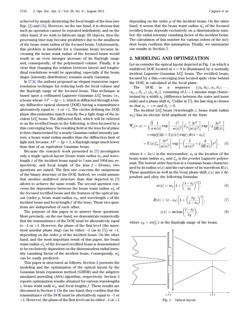
2. MODELING AND OPTIMIZATIONLet us consider the optical layout depicted in Fig. 1 in which amultilevel DOE located at z ¼ 0 is illuminated by a normallyincident Laguerre–Gaussian LG0
p beam. The rectified beam,focused by a thin converging lens located quite close behindthe DOE, is calculated at the focal plane.
The DOE is a sequence fðs0; θ0Þ; ðs1; θ1Þ; � � � ;ðsL−1; θL−1Þ; ðsL; θLÞg consisting of Lþ 1 annular rings charac-terized by a width sk (difference between the outer and innerradii) and a phase shift θk. Unlike in [7], the last ring is chosenso that sL ¼ þ∞ and θL ¼ 0.
The incident LG0p beam (wavelength λ, beam waist radius
w0) has its electric field amplitude of the form
Ψpðr; zÞ ¼ffiffiffi2π
r1
wðzÞ exp�−
r2
wðzÞ2�Lp
�2r2
wðzÞ2�exp
�−j
kr2
2RðzÞ�
× exp½jð2pþ 1ÞγðzÞ� exp½−jkðz − z0Þ�
¼ ΓðzÞLp
�2r2
wðzÞ2�exp
�−
�1
wðzÞ2 þ jk
2RðzÞ�r2�; ð5Þ
where k ¼ 2π=λ is the wavenumber, z0 is the location of thebeam waist radius w0, and Lp is the p-order Laguerre polyno-mial. The lowest order function is a Gaussian beam character-ized by its radiuswðzÞ and the curvature of its wavefront RðzÞ.These quantities as well as the Gouy phase shift γðzÞ are z de-pendent and obey the following formulas
wðzÞ ¼ w0
�1þ
�z − z0zR
�2�1
2
; ð6Þ
RðzÞ ¼ ðz − z0Þ�1þ
�zR
z − z0
�2�; ð7Þ
γðzÞ ¼ arctan�z − z0zR
�; ð8Þ
where zR ¼ πw20=λ is the Rayleigh range of the beam.
Fig. 1. Optical layout.
1710 J. Opt. Soc. Am. A / Vol. 28, No. 8 / August 2011 Cagniot et al.
A. ModelingIntroducing the ABCD matrix formalism, the rectified beampropagates through the following optical system locatedbehind the DOE:
�A BC D
�¼
�1 f0 1
�×
�1 0− 1
f 1
�: ð9Þ
The rectified beam, at a distance z behind the previousABCD optical system, is calculated using the Collinsformula [9]
Eðr; zÞ ¼ jkBexpð−jkzÞ exp
�−j
kD2B
r2�
×Z þ∞
0τðρÞΨpðρ; 0Þ exp
�−j
kA2B
ρ2�J0
�kBrρ�ρdρ;
ð10Þ
where τðρÞ represents the transmittance function of the DOEand J0 is the zero-order Bessel function of the first kind.
Equation (10) can be rewritten as
Eðr; zÞ ¼ ΓðzÞ jkBexpð−jkzÞ exp
�−j
kD2B
r2�
×
�XL−1l¼0
Δl
Zal
0Lpðαρ2Þ expð−Qρ2ÞJ0
�kBrρ�ρdρ
þ expðjθLÞZ þ∞
0Lpðαρ2Þ expð−Qρ2ÞJ0
�kBrρ�ρdρ
�;
ð11Þwhere rings radii al are defined by
�a−1 ¼ 0;∀l ≥ 0; al ¼ al−1 þ sl;
ð12Þ
and parameters α, Q, and Δl are defined by
8>><>>:
α ¼ 2wð0Þ2 ;
Q ¼ 1wð0Þ2 þ j k2
�AB þ 1
Rð0Þ
�;
Δl ¼ expðjθlÞ − expðjθlþ1Þ:ð13Þ
Recalling the Hankel transform,
Z þ∞
0Lpðαρ2Þ expð−Qρ2ÞJ0ðρxÞρdρ
¼ ðQ − αÞp2Qpþ1 exp
�−x2
4Q
�Lp
� αx24Qðα − QÞ
�; ð14Þ
where ReðQÞ > 0, Eq. (11) becomes
Eðr; zÞ ¼ ΓðzÞ jkBexpð−jkzÞexp
�−j
kD2B
r2�
×�XL−1
l¼0
Δl
Zal
0Lpðαρ2Þexpð−Qρ2ÞJ0
�krBρ�ρdρ
þ expðjθLÞðQ− αÞp2Qpþ1 exp
�−k2r2
4QB2
�Lp
� αk2r24Qðα−QÞB2
��:
ð15Þ
The rectified beam defined by Eq. (15) has to be calculatedthousands of times within an optimization process. Conse-quently, such a calculation must be performed in constanttime regardless of the radial coordinate r while providing avery good accuracy. The GBEM [10] satisfies these require-ments by transforming Eq. (15) into a finite sum of Hankeltransforms having known analytical expressions.
First, the circ function, defined by
circ
�ρa
�¼
�1; 0 ≤ ρ ≤ a;0; ρ > a;
ð16Þ
is introduced into Eq. (15), which becomes
Eðr; zÞ ¼ ΓðzÞ jkBexpð−jkzÞ exp
�−j
kD2B
r2�
×
�XL−1l¼0
Δl
Z þ∞
0circ
�ρal
�Lpðαρ2Þ
× expð−Qρ2ÞJ0
�krBρ�ρdρþ expðjθLÞ
ðQ − αÞp2Qpþ1
× exp
�−
k2r2
4QB2
�Lp
� αk2r24Qðα − QÞB2
��: ð17Þ
Second, the circ function is expanded onto a finite set ofcomplex Gaussian functions
circ�ρa
�≃
XN−1
n¼0
Fn exp�−Gn
a2ρ2�; ð18Þ
where coefficients Fn and Gn are obtained by optimization/computation. Consequently, Eq. (17) can be reformulated as
Eðr; zÞ≃ ΓðzÞ jkBexpð−jkzÞ exp
�−j
kD2B
r2�
×
�XL−1l¼0
Δl
XN−1
n¼0
Fn
Z þ∞
0Lpðαρ2Þ
× expð−QðlÞn ρ2ÞJ0
�krBρ�ρdρþ expðjθLÞ
ðQ − αÞp2Qpþ1
× exp
�−
k2r2
4QB2
�Lp
� αk2r24Qðα − QÞB2
��; ð19Þ
where
∀n < N; QðlÞn ¼ Qþ Gn
a2l: ð20Þ
Finally, by introducing Eq. (14) into Eq. (19), we derive ananalytical form for the rectified beam
Eðr;zÞ≃ΓðzÞ2
jkBexpð−jkzÞexp
�−jkD2B
r2�
×�XL−1
l¼0
Δl
XN−1
n¼0
FnðQðlÞn −αÞp
ðQðlÞn Þpþ1
×exp
�−
k2r2
4QðlÞn B2
�Lp
� αk2r2
4QðlÞn ðα−Ql
nÞB2
�þexpðjθLÞ
ðQ−αÞpQpþ1
×exp�−k2r2
4QB2
�Lp
� αk2r24Qðα−QÞB2
��: ð21Þ
Cagniot et al. Vol. 28, No. 8 / August 2011 / J. Opt. Soc. Am. A 1711
B. OptimizationGiven an arbitrary sequence consisting of Lþ 1 annular phaserings, the optimization problem consists in determining thesuitable widths sk and phase shifts θk so that the radial inten-sity of the rectified beam at the lens focal plane matches asclose as possible the one of a Gaussian beam (in the following,the latter will be referred to as the target Gaussian beam).Therefore, this problem involves 2Lþ 1 continuous variables:
1. The normalized radii Yl ¼ al=wð0Þ and the phase shiftsθl of the first L annular rings (the features of the last ring areknown), where wð0Þ represents the beam radius of the inci-dent Laguerre–Gaussian LG0
p beam at the DOE plane [seeEq. (6); note that wð0Þ ¼ w0 for a collimated incident beam].
2. α ∈ ð0; 1�, a parameter allowing control of the beamwaist radius of the target Gaussian beam at the lens focalplane, which is defined as
wðTGÞ0 ¼ α ×
λf
πwð0Þ�1þ
�fzR
�2�1
2
: ð22Þ
In other words, α is a corrective factor applied to the beamwaist radius of a Gaussian beam at the lens focal plane [seeEq. (3)] so that its shape fits one of the rectified beams asclose as possible.
The problem is solved using the ASA algorithm [11–13],which, unlike classical SA algorithms, automatically adjustsits behavior during the execution.
3. OPTIMIZATION RESULTSA. Hardware and Software SettingsComputations have been carried out on a Hewlett PackardZ400 Workstation (Intel 64 bit Quad-Core Xeon W35202:67GHz, 4Gbytes of DDR3 memory 1GHz, 8Mbytes of L2cache) running Linux kernel 2.6.35 (Fedora distribution—“Laughlin”). The application, written in C++, requires bothGNU Scientific Library (GSL) 1.14 (special mathematical func-tions and roots of polynomials) and ASA package 27.6 (gen-eric SA algorithm written in C). The executable file isgenerated using the GNU g++ compiler 4.5.1 and the followingoptimizations: -march=native (instruction set of the hostprocessor only), -funroll-loops (loop unrolling), -msse2-msse3 -mssse3 -msse4 (all available streaming instruc-tion sets for double precision floating point numbers) and-O3 (level 3 optimizations).
B. Numerical SettingsWe consider a collimated incident LG0
p beam [wð0Þ ¼ w0] anda multilevel DOE consisting of pþ 1 annular rings (L ¼ p).
Radial intensity distributions at the focal plane of the lens ofboth the rectified beam and the target Gaussian beam are
sampled on ð2pþ 1Þ × 1024 equidistant points in the semiopeninterval ½0; ð2pþ 1Þ ×wðTGÞ
0 Þ where wðTGÞ0 is defined by
Eq. (22). If I1ðiÞ and I2ðiÞ represent the intensities at theith radial coordinate of, respectively, the rectified beamand the target Gaussian beam, then the error in percents iscalculated as
err ¼Pi∣I1ðiÞ − I2ðiÞ∣P
iI1ðiÞ
× 100: ð23Þ
The circ function is expanded onto an accurate set of N ¼25 complex Gaussian functions taken from Table 3 of [14].
Settings of the ASA algorithm are the default ones. The costfunction to minimize is the error defined by Eq. (23). The re-annealing option, which prevents converging toward localminima, is enabled. Because the convergence of the algorithmis very sensitive to the starting configuration, we perform fivesuccessive runs with random starting configurations for everyconsidered incident beam. The domains of the variables are,respectively, Yl ∈ ½0:01; 3�, θl ∈ ½0; π�, and α ∈ ½0:01; 1�.
C. Test CasesTwo test cases have been investigated. The first one is takenfrom [7] (λ ¼ 1064 nm, w0 ¼ 1mm, f ¼ 50mm), while theother is λ ¼ 808 nm, w0 ¼ 1:5mm, and f ¼ 75mm. In bothcases, the optimization process has converged toward thesame solution. Consequently, the latter seems to be indepen-dent of λ, w0, and f . Table 1 lists the corresponding results.The columns represent, respectively, the order p of the inci-dent beam, the normalized radii Yl, and the phase shifts θl ofthe first p annular rings, the scaling parameter α, and finally,the error defined by Eq. (23).
As in [7], we can see that the superresolution technique,based upon an incident LG0
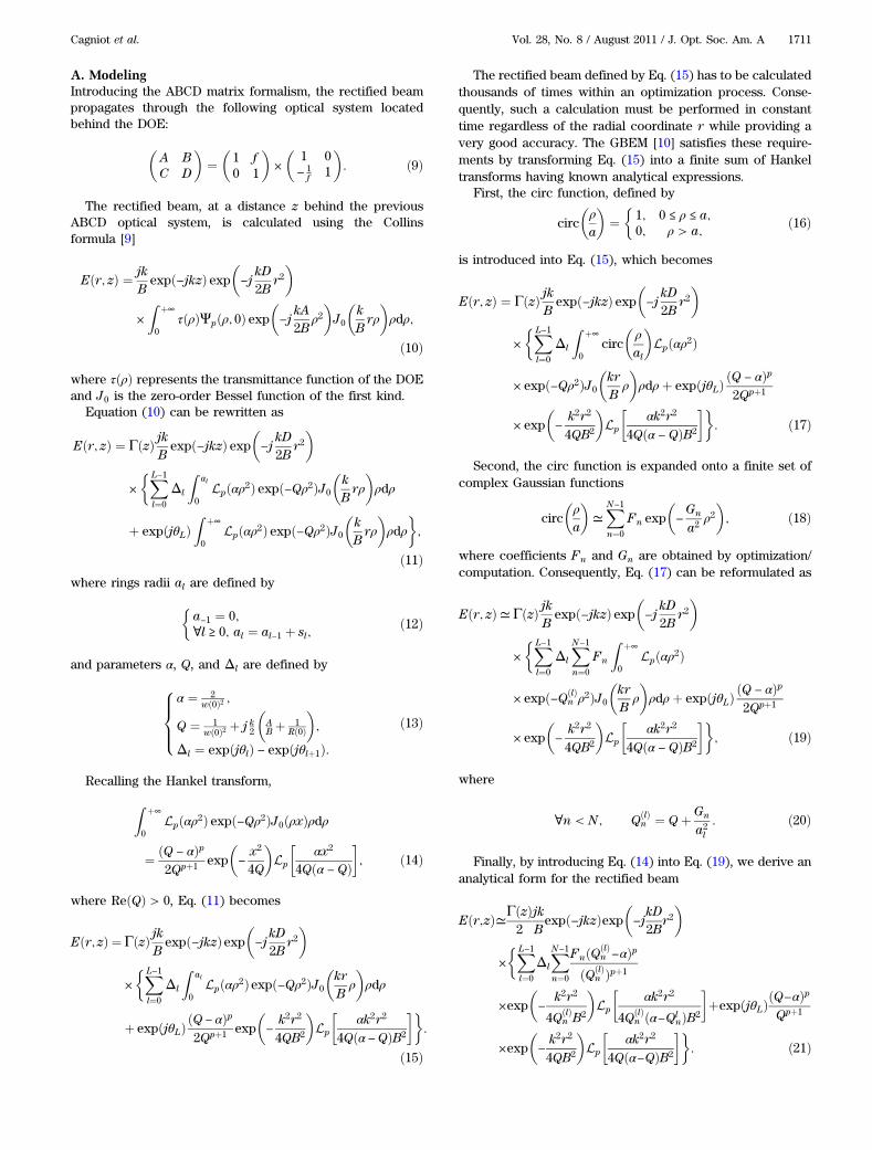
p beam, requires a binary structureconsisting of exactly pþ 1 annular rings whose normalizedradii are the zeros of the p-order Laguerre polynomial andwhose phase shifts are either 0 or π. Consequently, it isnow clear that a binary transmittance alternatively equal to−1 orþ1, transversely, represents the only solution to the pro-blem. Figure 2 depicts an incident LG0
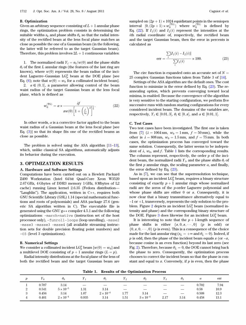
3 beam (normalized in-tensity and phase) and the corresponding binary structure ofthe DOE. Figure 3 does likewise for an incident LG0
4 beam.It is interesting to note that the pþ 1-length sequence of
phase shifts is either fπ; 0; π; � � � ; 0g (p is odd) orf0; π; 0; � � � ; 0g (p is even). This is a consequence of the choicemade for the last annular ring (sL ¼ þ∞ and θL ¼ 0). Indeed, ifp is odd, then the phase of the incident beam equals π (or −π,because cosine is an even function) beyond its last zero (seeFig. 2). Therefore, because θL ¼ 0, the DOE cannot bring backthe phase to zero. Consequently, the optimization processchooses to correct the incident beam so that the phase is con-stant and equal to π. Conversely, if p is even, then the phase
Table 1. Results of the Optimization Process
p Y 0 θ0 Y 1 θ1 Y 2 θ2 Y 3 θ3 α err
1 0.707 3.14 — — — — — — 0.702 7.942 0.541 5 × 10⁻⁵ 1.31 3.14 — — — — 0.58 10.93 0.456 3.14 1.07 2 × 10⁻⁴ 1.77 3.14 — — 0.508 12.34 0.401 2 × 10⁻⁴ 0.935 3.14 1.51 3 × 10⁻⁴ 2.17 3.14 0.458 13.1
1712 J. Opt. Soc. Am. A / Vol. 28, No. 8 / August 2011 Cagniot et al.
equals θL beyond the last zero (see Fig. 3). Consequently, theoptimization process corrects the incident beam so that thephase is constant and equal to 0.
4. DISCUSSIONStarting from the binary structure described above, we havesolved a restriction of the optimization problem in which α isthe unique variable. The second column of Table 2 lists thecorresponding results for various values of p. We can see thatα decreases slowly while p increases. Symmetrically, the errordefined by Eq. (23) increases slowly with respect to p.
Let us investigate the physical meaning of the scalingparameter α. If λ ¼ 1064 nm or λ ¼ 808nm then f ≪ zR. Con-sequently, Eq. (22) simplifies into
wðTGÞ0 ≃
λfπβw0
; ð24Þ
where β ¼ 1=α (note that β ≥ 1 because α ≤ 1). Hence, accord-ing to Eq. (4), it seems that focusing an incident collimatedGaussian beam (referred to as the source Gaussian beamin the following) whose beam waist radius is wSG
0 ¼β ×wTG
0 (wSG0 > wTG
0 ) results in the target Gaussian beam thatwould fit the rectified beam at the lens focal plane as close aspossible.
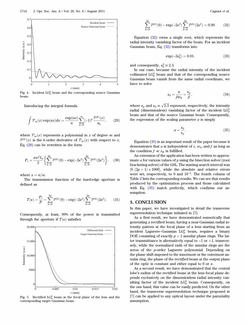
Figure 4 depicts an incident LG08 beam and the correspond-
ing source Gaussian beam (α ¼ 0:348). Figure 5 presents arectified LG0
8 beam at the focal plane of the lens and thecorresponding target Gaussian beam. Here, it is importantto recall that the beam quality factor of the rectified beamis exactly that of the incident beam, i.e., M2 ¼ 2pþ 1. FromFig. 4, it appears that the radial intensity of the incidentLaguerre–Gaussian LG0
p beam and that of the source Gaussianbeam vanishes from the same radial coordinate (note that thesame observation has been made whatever the order of theincident beam is). In other words, the two above beams sharethe same caustic surface. The radial intensity vanishing factorassociated to a Laguerre–Gaussian LG0
p beam, i.e., the factorso that the radial intensity is considered as negligible from co-ordinate r ≥ κ ×w where w represents the radius of the beam,is calculated as follows.
The radial intensity of the beam is defined by
IðrÞ ¼ I0
�Lp
�2r2
w2
��2exp
�2r2
w2
�; ð25Þ
while the power contained within the latter is calculated as
P ¼ 2πZ þ∞
0IðrÞrdr: ð26Þ
Making change of variable u ¼ 2r2=w2, Eq. (26) becomes
P ¼ πw2I02
Z þ∞
0LpðuÞLpðuÞ expð−uÞdu ¼ πw2I0
2; ð27Þ
because Laguerre polynomials form a complete basis on thesemiopened interval ½0;þ∞Þ with respect to the weighingfunction expð−uÞ.
The power transmitted through a hard-edge aperture whenilluminated under normal incidence by the beam describedabove is
Pt ¼πw2I0
2
Za
0P2pðuÞ expð−uÞdu; ð28Þ
where a is the radius of the aperture and P2pðuÞ ¼LpðuÞ × LpðuÞ is a polynomial in u of degree 2p.
-1
-0.5
0
0.5
1
0 0.5 1 1.5 2 2.5 3
Nor
mal
ized
Int
ensi
ty (
a.u.
) an
d Ph
ase
(pi.r
ad.)
r (mm)
IntensityPhaseDOE
Fig. 2. Incident LG03 beam and the corresponding binary structure.
-1
-0.5
0
0.5
1
0 0.5 1 1.5 2 2.5 3 3.5 4
Nor
mal
ized
Int
ensi
ty (
a.u.
) an
d Ph
ase
(pi.r
ad.)
r (mm)
IntensityPhase
DOE
Fig. 3. Incident LG04 beam and the corresponding binary structure.
Table 2. α as a Function of p
p ASA err Eq. (35)
1 0.702 7.94 0.7152 0.58 10.9 0.5893 0.508 12.3 0.5144 0.458 13.1 0.4625 0.421 13.6 0.4246 0.391 14 0.3937 0.368 14.3 0.3698 0.348 14.7 0.3499 0.332 15 0.331
10 0.318 15.3 0.31611 0.306 15.7 0.30312 0.295 15.8 0.29213 0.285 16 0.28114 0.276 16.1 0.27215 0.267 16.3 0.264
Cagniot et al. Vol. 28, No. 8 / August 2011 / J. Opt. Soc. Am. A 1713
Introducing the integral formula
ZPmðxÞ expðaxÞdx ¼ expðaxÞ
a
Xmk¼0
ð−1Þk PðkÞðxÞak
; ð29Þ
where PmðxÞ represents a polynomial in x of degree m andPðkÞðxÞ is the k-order derivative of PmðxÞ with respect to x,Eq. (28) can be rewritten in the form
Pt ¼πw2I0
2
�X2pk¼0
PðkÞð0Þ − expð−2κ2ÞX2pk¼0
PðkÞð2κ2Þ�; ð30Þ
where κ ¼ a=w.The transmission function of the hard-edge aperture is
defined as
TðκÞ ¼ Pt
P¼
X2pk¼0
PðkÞð0Þ − expð−2κ2ÞX2pk¼0
PðkÞð2κ2Þ: ð31Þ
Consequently, at least, 99% of the power is transmittedthrough the aperture if TðκÞ satisfies
X2pk¼0
PðkÞð0Þ − expð−2κ2ÞX2pk¼0
PðkÞð2κ2Þ ¼ 0:99: ð32Þ
Equation (32) owns a single root, which represents theradial intensity vanishing factor of the beam. For an incidentGaussian beam, Eq. (32) transforms into
expð−2κ20Þ ¼ 0:01; ð33Þ
and consequently, κ20 ≃ 2:3.In our case, because the radial intensity of the incident
collimated LG0p beam and that of the corresponding source
Gaussian beam vanish from the same radial coordinate, wehave to solve
κ0 ¼a
βw0¼ κp
β ; ð34Þ
where κp and κ0 ≃ffiffiffiffiffiffiffi2:3
prepresent, respectively, the intensity
radial (dimensionless) vanishing factor of the incident LG0p
beam and that of the source Gaussian beam. Consequently,the expression of the scaling parameter α is simply
α ¼ κ0κp
: ð35Þ
Equation (35) is an important result of the paper because itdemonstrates that α is independent of λ, w0, and f as long asthe condition f ≪ zR is fulfilled.
An extension of the application has been written to approx-imate α for various values of p using the bisection solver (rootbracketing solver) of the GSL. The starting search interval was½0; ð2pþ 1Þ × 1000�, while the absolute and relative errorswere set, respectively, to 0 and 10−3. The fourth column ofTable 2 lists the corresponding results. We can see that resultsproduced by the optimization process and those calculatedwith Eq. (35) match perfectly, which confirms our as-sumption.
5. CONCLUSIONIn this paper, we have investigated in detail the transversesuperresolution technique initiated in [7].
As a first result, we have demonstrated numerically thatgenerating a rectified beam, having a near-Gaussian radial in-tensity pattern at the focal plane of a lens starting from anincident Laguerre–Gaussian LG0
p beam, requires a binaryDOE consisting of exactly pþ 1 annular phase rings. The lat-ter transmittance is alternatively equal to −1 or þ1, transver-sely, while the normalized radii of the annular rings are thezeros of the p-order Laguerre polynomial. Depending onthe phase shift imposed to the innermost or the outermost an-nular ring, the phase of the rectified beam at the output planeof the optic is constant and either equal to 0 or π.
As a second result, we have demonstrated that the centrallobe’s radius of the rectified beam at the lens focal plane de-pends exclusively on the dimensionless radial intensity van-ishing factor of the incident LG0
p beam. Consequently, onthe one hand, this value can be easily predicted. On the otherhand, the transverse superresolution technique proposed in[7] can be applied to any optical layout under the paraxialityassumption.
0
0.1
0.2
0.3
0.4
0.5
0.6
0.7
0 1 2 3 4 5
Inte
nsity
(a.
u.)
r (mm)
Incident beam
Source Gaussian beam
Fig. 4. Incident LG08 beam and the corresponding source Gaussian
beam.
0
5000
10,000
15,000
20,000
0 0.005 0.01 0.015 0.02
Inte
nsity
(a.
u.)
r (mm)
Diffracted field
Target Gaussian beam
Fig. 5. Rectified LG08 beam at the focal plane of the lens and the
corresponding target Gaussian beam.
1714 J. Opt. Soc. Am. A / Vol. 28, No. 8 / August 2011 Cagniot et al.

ACKNOWLEDGMENTSThe authors acknowledge the support of the Conseil RégionalBasse Normandie.
REFERENCES1. W. H. Teh, U. Durig, G. Salis, R. Harbers, U. Drechsler, R. F.
Mahrt, C. G. Smith, and H. J. Guntherodt, “SU-8 for realthree-dimensional subdiffraction-limit two-photon microfabrica-tion,” Appl. Phys. Lett. 84, 4095–4097 (2004).
2. R. Infuehr, N. Pucher, C. Heller, H. Lichtenegger, R. Liska, V.Schmidt, L. Kuna, A. Haase, and J. Stampfl, “Functional poly-mers by two-photon 3D lithography,” Appl. Surf. Science 254,836–840 (2007).
3. W. Denk, J. H. Strickler, and W. W. Webb, “Two-photon laserscanning fluorescence microscopy,” Science 248, 73–76 (1990).
4. W. R. Zipfel, R. M. Williams, and W. W. Webb, “Nonlinear magic:multiphoton microscopy in the biosciences,” Nat. Biotechnol.21, 1369–1377 (2003).
5. A. Ashkin, J. M. Dziedzic, and T. Yamane, “Optical trapping andmanipulation of single cells using infrared laser beams,” Nature330, 769–771 (1987).
6. J. R. Moffitt, Y. R. Chemla, S. B. Smith, and C. Bustamante, “Re-cent advances in optical tweezers,” Annu. Rev. Biochem. 77,205–228 (2008).
7. A. Hasnaoui, A. Bencheikh, M. Fromager, E. Cagniot, and K.Aït-Ameur, “Creation of a sharper focus by using a rectifiedTEMp0 beam,” Opt. Commun. 284, 1331–1334 (2011).
8. A. Hasnaoui, A. Bencheikh, M. Fromager, E. Cagniot, and K.Aït-Ameur, “Erratum to ‘Creation of a sharper focus by usinga rectified TEMp0 beam’,” Opt. Commun. 284, 4107–4107 (2011).
9. S. A. Collins, Jr., “Lens-system diffraction integral written interms of matrix optics,” J. Opt. Soc. Am. 60, 1168–1177 (1970).
10. J. J. Wen and M. A. Breazeale, “A diffraction beam field ex-pressed as the superposition of Gaussian beams,” J. Acoust.Soc. Am. 83, 1752–1756 (1988).
11. L. Ingber, “Very fast simulated re-annealing, Math. Comput.Model. 12, 967–973 (1989).
12. L. Ingber, “Simulated annealing: Practice versus theory,” Math.Comput. Model. 18, 29–57 (1993).
13. L. Ingber, “Adaptive simulated annealing (ASA): Lessonslearned,” Contr. Cybernet. 25, 33–54 (1996).
14. W. Liu, P. Ji, and J. Yang, “Development of a simple andaccurate approximation method for the Gaussian beam ex-pansion technique,” J. Acoust. Soc. Am. 123, 3516–3516(2008).
Cagniot et al. Vol. 28, No. 8 / August 2011 / J. Opt. Soc. Am. A 1715


![Homology of gaussian groups - Centre Mersenne · 493 1.1. Gaussian and locally Gaussian monoids. Our notations follow those of [42] on the one hand, and those of [25] and [23] on](https://img.pdfslide.fr/doc/110x75/5fd4001a720ab320977220ad/homology-of-gaussian-groups-centre-mersenne-493-11-gaussian-and-locally-gaussian.jpg)