Embed Size (px)
Citation preview
VIGILANT 800/I
Manuale di installazione
Installation manual
Installationsanleitung
Manuel d'installation
Manual de instalación
I Dissuasore di sosta e passaggio
Brevettato
Patented
Made in Italy
RL
8542003 -
Rev.0
4
GB Parking and passage rising bollard
D Poller gegen unrechtmäßiges Parken und Durchfahren
F Borne escamotable anti-stationnement et anti-accès
E Disuasor de tránsito de aparcamiento y de paso
2 - VIGILANT
The undersigned Mr. Luigi Benincà, legal representative of the company Rise S.r.l. - Via del Capitello, 42 - 36035 Marano
Vicentino (VI) – in the capacity of manufacturer declares that the product:
VIGILANT 800/Icomplies in all its components with Directives:
- EMC Directive 2004/108/EC
- Low Voltage Directive 2006/95/EC
as per checks carried out by: ECO Certiicazioni S.p.A., via Mengolina, 33 - 48018 Faenza (RA)
Marano Vicentino, 30/11/10
The legal representative
GBDeclaration of conformity
¯ 327
¯ 200
800
¯ 244.5
1237~ 1,2 m
¯ 340
265
54
1306
GBOverall Dimensions
VIGILANT - 3
GB General information and technical speciications
We thank you for having chosen one of our Vigilant model automatic rising bollards.
All articles in the Rise range are the fruit of long experience in the sector of mechanical and electronic automations.
This is why today we are able to offer extremely innovative and reliable automatic rising bollards that, thanks to their per-
formance, eficiency and durability, fully satisfy the inal customer’s requirements.
All our products are covered by a two-year warranty.
Furthermore, a product Civil Liability policy stipulated with a leading insurance company covers any damage to things or
persons caused by manufacturing defects.
General information
The Vigilant 800/I automatic rising bollard, with its high resistance to impact and elegant design, is suitable for installation
in public or commercial areas and is particularly indicated for protecting of buildings.
The standard version, manufactured in steel, is painted with electrophoresis painting, a corrosion-proof treatment that
guarantees an extremely elevated resistance to the elements and to salty environments.
The bollard is operated with 24Vdc; an amperometric sensor detects any obstacles when rising and inverts the movement
immediately. The bollard is itted with 12 leds that operate in sequence and with a high-visibility relecting band. The bollard
can be easily unlocked in an emergency. In the event of a power cut different functions can be selected: the bollard can
remain in raised position or can be unlocked and lowered by keeping the emergency button pressed; automatic lowering
in the event of a power cut is also available (accessory). The system can also be itted with an uninterrupted power supply
unit (accessory) that allows the bollard to be used in automatic mode even in the event of a power cut.
The foundation case is manufactured in cataphoresis-painted steel and can easily be assembled on site before installation.
If the bollard is not installed immediately, a cover for closing the hole is available.
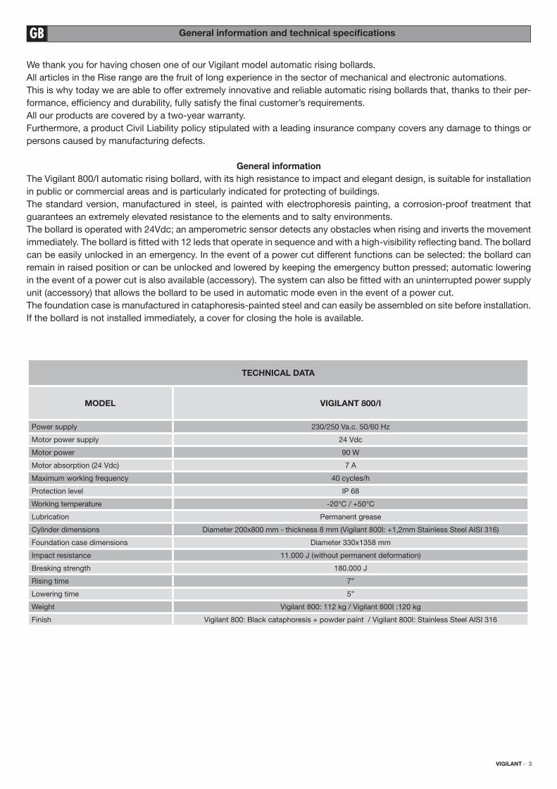
TECHNICAL DATA
MODEL VIGILANT 800/I
Power supply 230/250 Va.c. 50/60 Hz
Motor power supply 24 Vdc
Motor power 90 W
Motor absorption (24 Vdc) 7 A
Maximum working frequency 40 cycles/h
Protection level IP 68
Working temperature -20°C / +50°C
Lubrication Permanent grease
Cylinder dimensions Diameter 200x800 mm - thickness 8 mm (Vigilant 800I: +1,2mm Stainless Steel AISI 316)
Foundation case dimensions Diameter 330x1358 mm
Impact resistance 11.000 J (without permanent deformation)
Breaking strength 180.000 J
Rising time 7”
Lowering time 5”
Weight Vigilant 800: 112 kg / Vigilant 800I :120 kg
Finish Vigilant 800: Black cataphoresis + powder paint / Vigilant 800I: Stainless Steel AISI 316
4 - VIGILANT
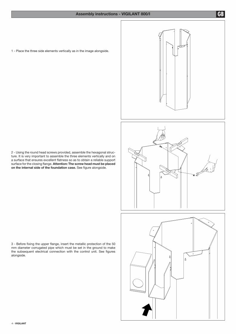
1 - Place the three side elements vertically as in the image alongside.
2 - Using the round head screws provided, assemble the hexagonal struc-
ture. It is very important to assemble the three elements vertically and on
a surface that ensures excellent latness so as to obtain a reliable support
surface for the closing lange. Attention: The screw head must be placed
on the internal side of the foundation case. See igure alongside.
3 - Before ixing the upper lange, insert the metallic protection of the 50
mm diameter corrugated pipe which must be set in the ground to make
the subsequent electrical connection with the control unit. See igures
alongside.
GBAssembly instructions - VIGILANT 800/I
VIGILANT - 5
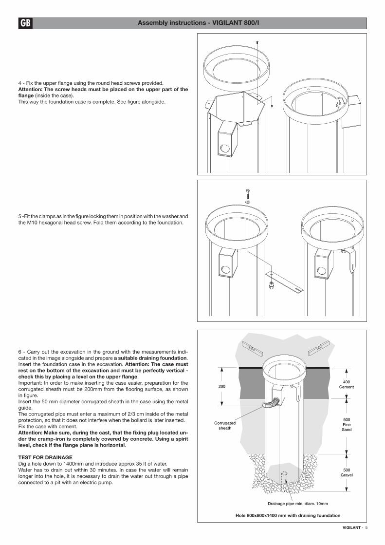
4 - Fix the upper lange using the round head screws provided.
Attention: The screw heads must be placed on the upper part of the
lange (inside the case).
This way the foundation case is complete. See igure alongside.
5 -Fit the clamps as in the igure locking them in position with the washer and
the M10 hexagonal head screw. Fold them according to the foundation.
6 - Carry out the excavation in the ground with the measurements indi-
cated in the image alongside and prepare a suitable draining foundation.
Insert the foundation case in the excavation. Attention: The case must
rest on the bottom of the excavation and must be perfectly vertical -
check this by placing a level on the upper lange.
Important: In order to make inserting the case easier, preparation for the
corrugated sheath must be 200mm from the looring surface, as shown
in igure.
Insert the 50 mm diameter corrugated sheath in the case using the metal
guide.
The corrugated pipe must enter a maximum of 2/3 cm inside of the metal
protection, so that it does not interfere when the bollard is later inserted.
Fix the case with cement.
Attention: Make sure, during the cast, that the ixing plug located un-
der the cramp-iron is completely covered by concrete. Using a spirit
level, check if the lange plane is horizontal.
TEST FOR DRAINAGE
Dig a hole down to 1400mm and introduce approx 35 lt of water.
Water has to drain out within 30 minutes. In case the water will remain
longer into the hole, it is necessary to drain the water out through a pipe
connected to a pit with an electric pump.
Hole 800x800x1400 mm with draining foundation
400
Cement
Corrugated
sheath
500
Fine
Sand
500
Gravel
Drainage pipe min. diam. 10mm
200
GB Assembly instructions - VIGILANT 800/I
6 - VIGILANT
GBAssembly instructions - VIGILANT 800/I
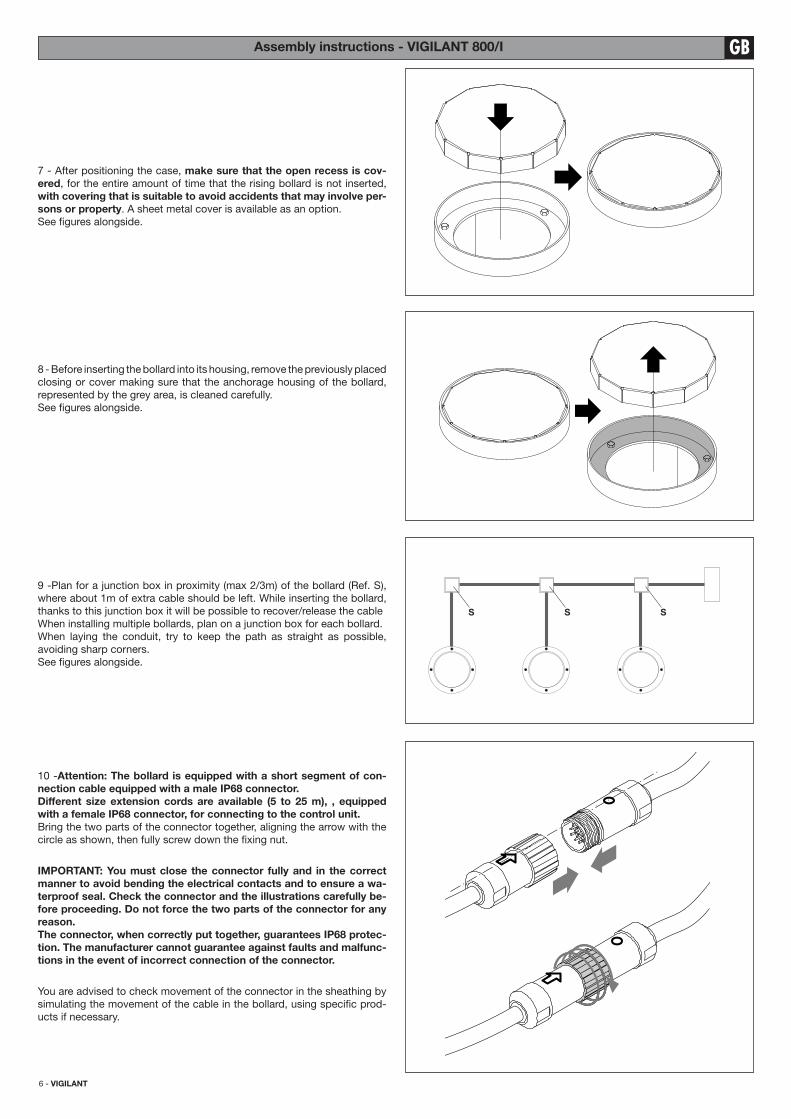
9 -Plan for a junction box in proximity (max 2/3m) of the bollard (Ref. S),
where about 1m of extra cable should be left. While inserting the bollard,
thanks to this junction box it will be possible to recover/release the cable
When installing multiple bollards, plan on a junction box for each bollard.
When laying the conduit, try to keep the path as straight as possible,
avoiding sharp corners.
See igures alongside.
8 - Before inserting the bollard into its housing, remove the previously placed
closing or cover making sure that the anchorage housing of the bollard,
represented by the grey area, is cleaned carefully.
See igures alongside.
7 - After positioning the case, make sure that the open recess is cov-
ered, for the entire amount of time that the rising bollard is not inserted,
with covering that is suitable to avoid accidents that may involve per-
sons or property. A sheet metal cover is available as an option.
See igures alongside.
S S S
10 -Attention: The bollard is equipped with a short segment of con-
nection cable equipped with a male IP68 connector.
Different size extension cords are available (5 to 25 m), , equipped
with a female IP68 connector, for connecting to the control unit.
Bring the two parts of the connector together, aligning the arrow with the
circle as shown, then fully screw down the ixing nut.
IMPORTANT: You must close the connector fully and in the correct
manner to avoid bending the electrical contacts and to ensure a wa-
terproof seal. Check the connector and the illustrations carefully be-
fore proceeding. Do not force the two parts of the connector for any
reason.
The connector, when correctly put together, guarantees IP68 protec-
tion. The manufacturer cannot guarantee against faults and malfunc-
tions in the event of incorrect connection of the connector.
You are advised to check movement of the connector in the sheathing by
simulating the movement of the cable in the bollard, using speciic prod-
ucts if necessary.
VIGILANT - 7
GB Assembly instructions - VIGILANT 800/I
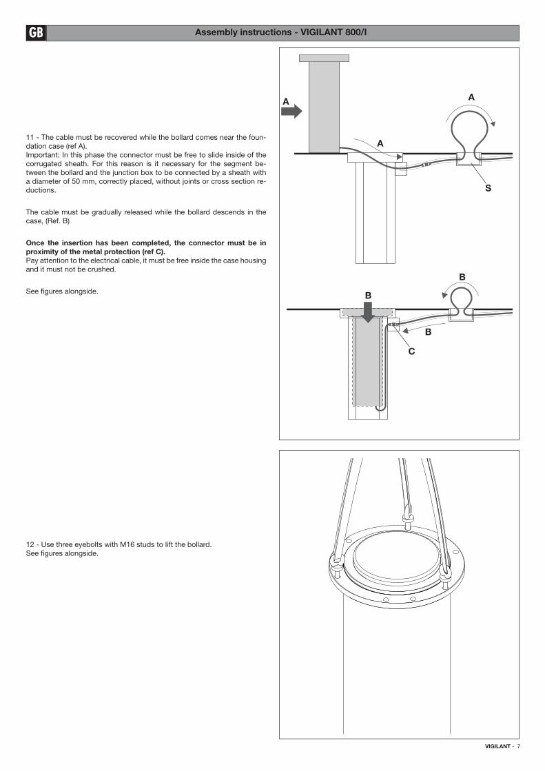
12 - Use three eyebolts with M16 studs to lift the bollard.
See igures alongside.
11 - The cable must be recovered while the bollard comes near the foun-
dation case (ref A).
Important: In this phase the connector must be free to slide inside of the
corrugated sheath. For this reason is it necessary for the segment be-
tween the bollard and the junction box to be connected by a sheath with
a diameter of 50 mm, correctly placed, without joints or cross section re-
ductions.
The cable must be gradually released while the bollard descends in the
case, (Ref. B)
Once the insertion has been completed, the connector must be in
proximity of the metal protection (ref C).
Pay attention to the electrical cable, it must be free inside the case housing
and it must not be crushed.
See igures alongside.
S
A
B
A
A
B
B
C
8 - VIGILANT
GBAssembly instructions - VIGILANT 800/I
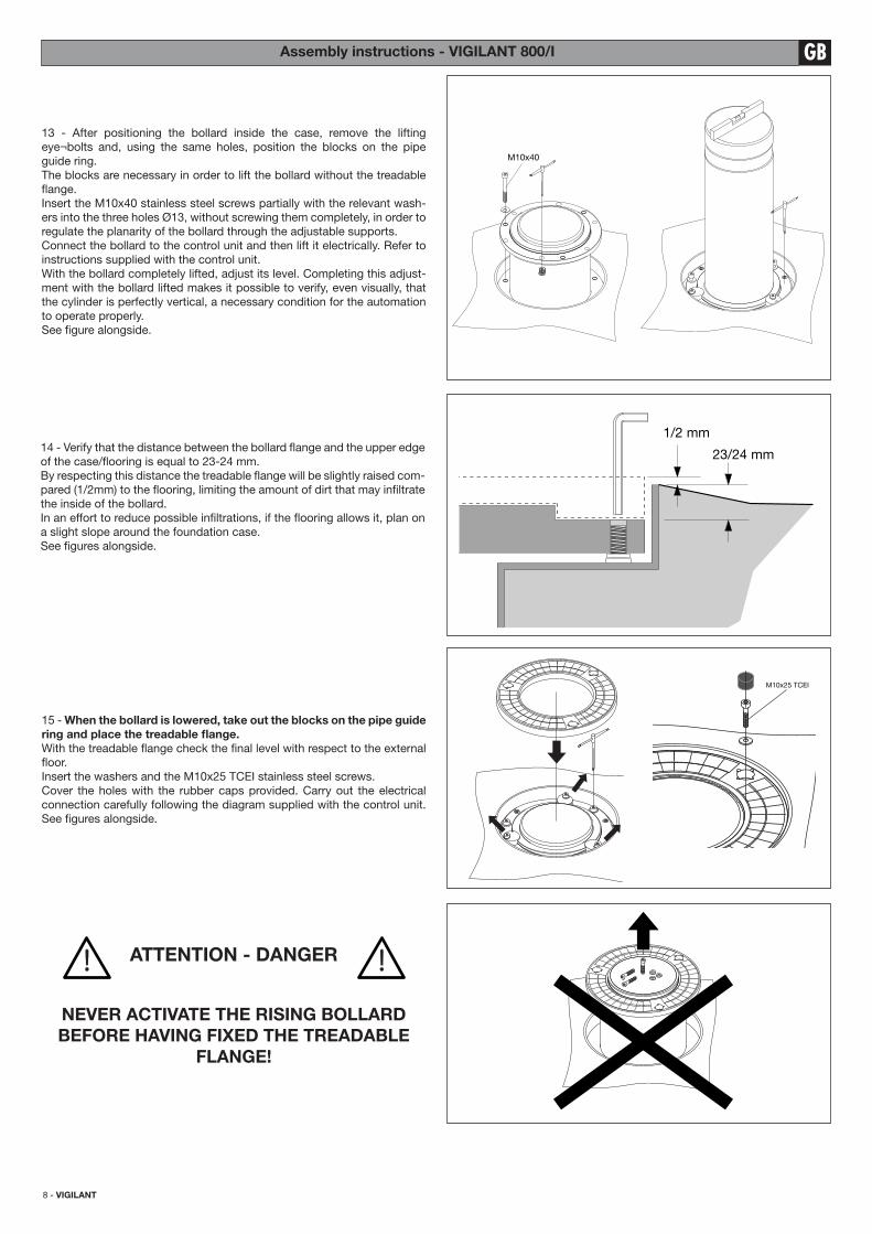
15 - When the bollard is lowered, take out the blocks on the pipe guide
ring and place the treadable lange.
With the treadable lange check the inal level with respect to the external
loor.
Insert the washers and the M10x25 TCEI stainless steel screws.
Cover the holes with the rubber caps provided. Carry out the electrical
connection carefully following the diagram supplied with the control unit.
See igures alongside.
ATTENTION - DANGER
NEVER ACTIVATE THE RISING BOLLARD
BEFORE HAVING FIXED THE TREADABLE
FLANGE!
M10x25 TCEI
M10x40
1/2 mm
23/24 mm14 - Verify that the distance between the bollard lange and the upper edge
of the case/looring is equal to 23-24 mm.
By respecting this distance the treadable lange will be slightly raised com-
pared (1/2mm) to the looring, limiting the amount of dirt that may iniltrate
the inside of the bollard.
In an effort to reduce possible iniltrations, if the looring allows it, plan on
a slight slope around the foundation case.
See igures alongside.
13 - After positioning the bollard inside the case, remove the lifting
eye¬bolts and, using the same holes, position the blocks on the pipe
guide ring.
The blocks are necessary in order to lift the bollard without the treadable
lange.
Insert the M10x40 stainless steel screws partially with the relevant wash-
ers into the three holes Ø13, without screwing them completely, in order to
regulate the planarity of the bollard through the adjustable supports.
Connect the bollard to the control unit and then lift it electrically. Refer to
instructions supplied with the control unit.
With the bollard completely lifted, adjust its level. Completing this adjust-
ment with the bollard lifted makes it possible to verify, even visually, that
the cylinder is perfectly vertical, a necessary condition for the automation
to operate properly.
See igure alongside.
VIGILANT - 9
GB Spare parts list - VIGILANT 800
3
4
5
6
7
8
8b
1b
9
10
11
1
2
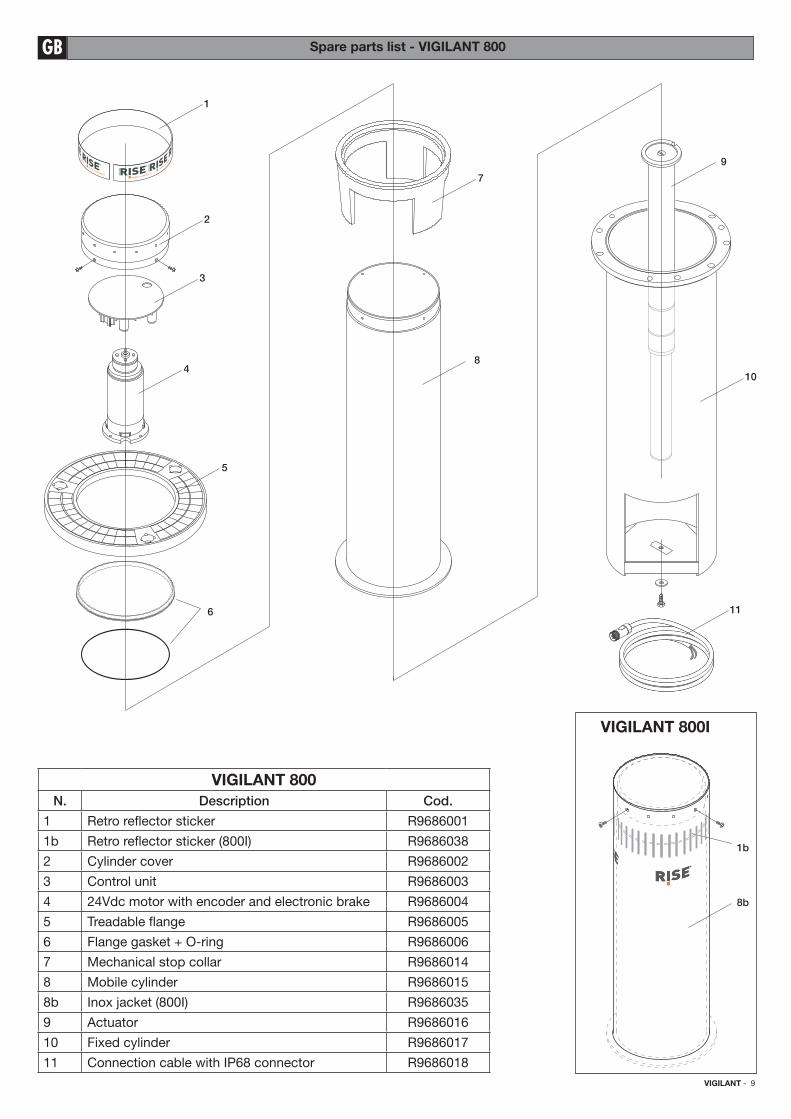
VIGILANT 800
N. Description Cod.
1 Retro relector sticker R9686001
1b Retro relector sticker (800I) R9686038
2 Cylinder cover R9686002
3 Control unit R9686003
4 24Vdc motor with encoder and electronic brake R9686004
5 Treadable lange R9686005
6 Flange gasket + O-ring R9686006
7 Mechanical stop collar R9686014
8 Mobile cylinder R9686015
8b Inox jacket (800I) R9686035
9 Actuator R9686016
10 Fixed cylinder R9686017
11 Connection cable with IP68 connector R9686018
VIGILANT 800I
10 - VIGILANT
GBUser instructions - VIGILANT 800/I
SAFETY STANDARDS
ATTENTION:
Carefully read the instructions manual in all of its pars and keep it in a safe location for any future consultation.
Not following the standards and warnings included in the present manual or an incorrect installation may damage per-
sons or property.
- This product has been designed and manufactured exclusively for the use indicated in this documentation. Any non-conforming
use may damage the product or be a source of danger for persons and/or property.
- Do not install the product in an explosive atmosphere: the presence of lammable gasses or vapours is a source a serious
danger.
- Installation must be completed in observance of current standards.
- For installation in countries outside of the EEC, besides national reference regulations, the above mentioned standards and
warnings must be obeyed in order to obtain a suitable level of safety.
- Verify that the system has been earthed according to Good Practice standards and the metal parts must be connected to it.
- For each system, a suitable sign is recommended.
- Do not stand in the movement area of the bollard.
- Do not leave packaging materials (plastic, polystyrene, wood ...) within reach of children because they may be a potential
source of danger.
- Do not allow children to play with the commands or in proximity of the bollard.
- In the case of functioning anomalies do not attempt to repair the fault but contact a specialised technician. Only use original
RISE Srl accessories.
- Do not modify any components that are part of the RISE system. Any modiication, alterations or tampering with the RISE
system, or the use of non original RISE accessories, will cause the product warranty to lapse and RISE Srl declines any re-
sponsibility with regards to safety and proper system operation.
- The installer must provide the user with all information necessary for system use and maintenance along with manual and
emergency manoeuvres. He must deliver them and the user must request the booklet containing warnings and use and main-
tenance standards.
- The bollard must be completely lowered before transiting through the controlled passage area.
- Anything that is not speciically planned for in these instructions is not allowed.
ATTENTION: PRECAUTIONS FOR USE
In case of looding or signiicant precipitation that causes obvious drainage problems, avoid using the bollard until normal
conditions have been restored.
MANUAL EMERGENCY MANOEUVRE
In the event of a power cut or of malfunction the bollard can be unlocked with the emergency switch itted close to the control
unit. Keep the switch pressed to lower the bollard.
Control units for 2/4 bollards are equipped with ABC clamps that raise or lower the bollard even in case of complete control unit
malfunction and without mains power supply.
MAINTENANCE
- Replace the buffer battery in the control unit maximum every 2 years. Dispose of them in compliance with the Standards in
force.
- Absolutely avoid attempting to carry out repairs: you could cause accidents; for such operations call a specialised techni-
cian.
Maintenance to bollards, control units and the entire system must be completed exclusively by specialised technical personnel.
The RISE bollards do not require any special maintenance, periodically checking that the area around the bollard is suf-
iciently clean and, as needed, the gaskets at the base of the bollard should be replaced. Programmed routine controls
of the entire system are recommended only in cases of intense product use in order to ensure correct operation and long
product life.
Check the state and eficiency of the control unit and UPS unit batteries at least once a year and, if necessary, have them
replaced. The batteries must be replaced at least once every two years. For other instructions regarding product mainte-
nance consult the technical manuals supplied with the bollards and control units.
DISPOSAL
If the bollard is withdrawn from service, the current laws and regulations in force concerning the separate waste disposal
and the recycling of the various components (metals, plastics, electric cables etc.) must be respected; it is advisable to
contact your installer or a specialised company, authorised for the purpose.
ATTENTION
All RISE products are covered by an insurance policy that answers for any damage to things or persons caused by manu-
facturing defects.


RISE S.r.l. - Via Capitello di Sopra, 42 - 36035 Marano Vicentino (VI) - Tel.: +39 0444 751401 - Fax: +39 0444 758049
www.riseweb.it - [email protected]