Motion
G
G1CT17 FEP 3.1
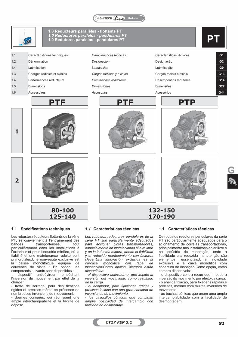
1.1 Caractéristiques techniques Características técnicas Características técnicas G1
1.2 Dénomination Designación Designação G2
1.4 Lubrification Lubricación Lubrificação G9
1.3 Charges radiales et axiales Cargas radiales y axiales Cargas radiais e axiais G13
1.4 Performances réducteurs Prestaciones reductores Desempenhos redutores G14
1.5 Dimensions Dimensiones Dimensões G22
1.6 Accessoires Accesorios Acessórios G44
PTF PTP
80-100125-140
132-150170-190
Los robustos reductores pendulares de laserie PT son particularmente adecuadospara accionar cintas transportadoras,especialmente en instalaciones al aire librey en la industria minera, donde la fiabilidady el reducido mantenimiento son factoresclave.¡Una innovación exclusiva es lacarcasa monolítica con tapa deinspección!Como opción, siempre estándisponibles:- el dispositivo antirretorno, que impide lainversión del movimiento como resultadode la carga.- el acoplador, para fijaciones rígidas yprecisas incluso con una gran cantidad deinversiones de movimiento.- los casquillos cónicos, que combinanamplia posibilidad de intercambio confacilidad de desmontaje.
Les robustes réducteurs flottants de la sériePT, se conviennent à l’entraînement desbandes transporteuses, toutparticulièrement dans les installations àl’extérieur et pour l’industrie minière, où lafiabilité et une maintenance réduite sontprimordiales.Une nouveauté exclusive estla caisse monolithique équipée decouvercle de visite ! En option, lescomposants suivants sont disponibles :- dispositif antidévireur, empêchantl’inversion du mouvement par effet de lacharge ;- frette de serrage, pour des fixationsrigides et précises même en présence denombreuses inversions du mouvement.- douilles coniques, qui réunissent uneample interchangeabilité et la facilité dedépose.
Os robustos redutores pendulares da sériePT são particularmente adequados para oacionamento de correias transportadoras,principalmente nas instalações ao ar livre ena indústria de mineração, onde afiabilidade e a reduzida manutenção sãoelementos essenciais.Uma novidadeexclusiva é a caixa monolítica comcobertura de inspeção!Como opção, estãosempre disponíveis:- o dispositivo contra-recuo que impede ainversão do movimento por efeito da carga.- o anel de fixação, para fixagens rápidas eprecisas, mesmo com muitas inversões demovimento.- as buchas cónicas que unem uma amplaintercambiabilidade com a facilidade dedesmontagem.
1.1 Características técnicas 1.1 Características técnicas1.1 Spécifications techniques
1
2
PTF
PT1.0 Réducteurs parallèles - flottants PT1.0 Reductores paralelos - pendulares PT1.0 Redutores paralelos - pendulares PT
PT
Motion
CT17 FEP 3.1G2
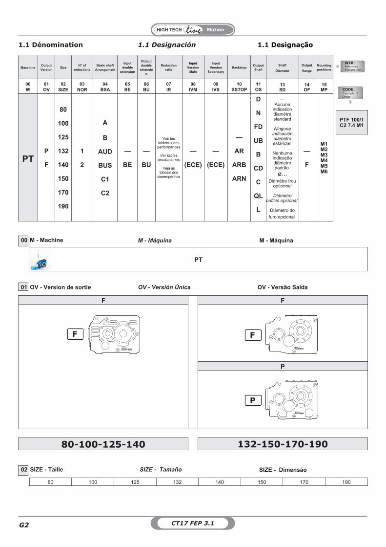
MaschineOutputVersion
SizeN° of
reductionsBasic shaft
Arrangement
Inputdouble
extension
Outputdouble
extension
Reductionratio
InputVersion
Main
InputVersion
SecondaryBackstop
OutputShaft
Shaft
Diameter
Output
flange
Mountingpositions
00M
01OV
02SIZE
03NOR
04BSA
05BE
06BU
07IR
08IVM
09IVS
10BSTOP
11OS
13SD
14OF
15MP
PTP
F
80
100
125
132
140
150
170
190
1
2
A
B
AUD
BUS
C1
C2
—
BE
—
BU
Voir lestableaux desperformances
Ver tablasprestaciones
Veja astabelas dos
desempenhos
—
(ECE)
—
(ECE)
—
AR
ARB
ARN
D
N
FD
UB
B
CD
C
QL
L
—Aucune
indicationdiamètrestandard
Ningunaindicacióndiámetroestándar
Nenhumaindicaçãodiâmetropadrão
ø...Diamètre trou
optionnel
Diámetroorificio opcional
Diâmetro do
furo opcional
—
F
M1M2M3M4M5M6
M - Machine M - Máquina M - Máquina00
PT
WEB:Reference
Designation
CODE:Example of
Order
PT
01 OV - Version de sortie OV - Versión Única OV - Versão Saída
80-100-125-140 132-150-170-190
PTF 100/1C2 7.4 M1
SIZE - Taille SIZE - Tamaño SIZE - Dimensão02
80 100 125 132 140 150 170 190
1.1 Dénomination 1.1 Designación 1.1 Designação
F
F F
P
F
P
Motion
G
G3CT17 FEP 3.1
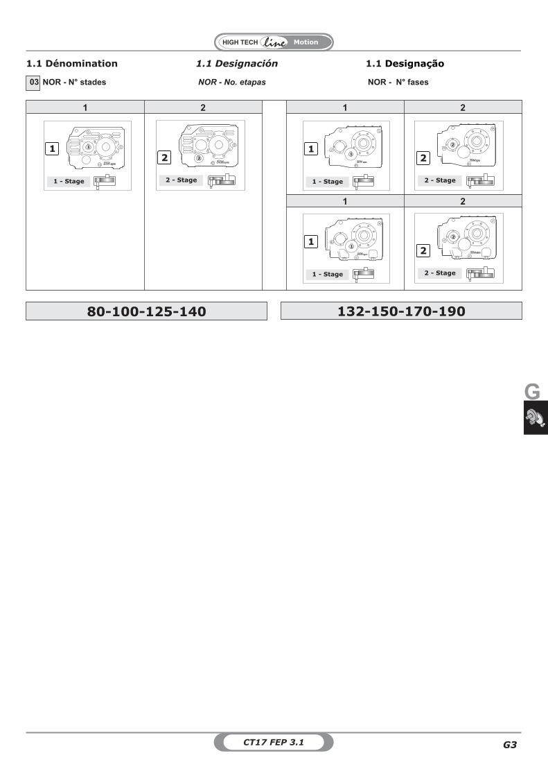
NOR - N° stades NOR - No. etapas NOR - N° fases03
80-100-125-140 132-150-170-190
1.1 Dénomination 1.1 Designación 1.1 Designação
1
1 - Stage
1
1 2 1 2
1 2
1
1 - Stage
1
2
2 - Stage
2
2
2 - Stage
2
1
1 - Stage
1
2
2 - Stage
2
Motion
CT17 FEP 3.1G4
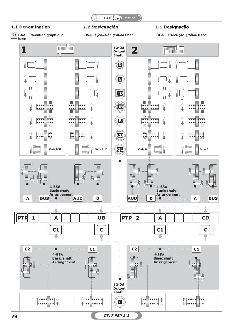
BSA - Exécution graphiquebase
BSA - Ejecución gráfica Base BSA - Execução gráfica Base04
1.1 Dénomination 1.1 Designación 1.1 Designação
CD
DB
UB
DFD
DN
DD
AUDA
C2 C1
1
AUD A
C2 C1
2
DC
1PTP A UB 2PTP A CD
C1 C C1 C
12-OSOutputShaft
4-BSABasic shaftArrangement
QL
BUS B B BUS
Only AUD Only B Only AOnly BUS
12-OSOutputShaft
4-BSABasic shaftArrangement
4-BSABasic shaftArrangement
4-BSABasic shaftArrangement
Motion
G
G5CT17 FEP 3.1
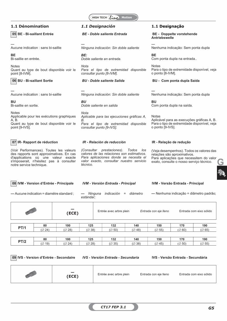
BE - Bi-saillant Entrée BE - Doble saliente Entrada BE - Doppelte vorstehendeAntriebswelle
05
BU - Bi-saillant Sortie BU - Doble saliente Salida BU - Com ponta dupla Saída06
(Voir Performances). Toutes les valeursdes rapports sont approximatives. En casd'applications où une valeur exactes'imposerait, n'hésitez pas à consulternotre service technique.
IR- Rapport de réduction IR - Relación de reducción IR - Relação de redução07
(Consultar prestaciones). Todos losvalores de las relaciones son estimativos.Para aplicaciones donde se necesita elvalor exacto, consultar nuestro serviciotécnico.
(Veja desempenhos). Todos os valores dasrelações são aproximativos.Para aplicações que necessitem do valorexato, consulte o nosso serviço técnico.
—Aucune indication : sans bi-saillie
BEBi-saillie en entrée.
NotesQuant au type de bout disponible voir lepoint [8-IVM].
—Ninguna indicación: Sin doble saliente
BE:Doble saliente en entrada.
NotaPara el tipo de extremidad disponibleconsultar punto [8-IVM].
—Nenhuma indicação: Sem ponta dupla
BECom ponta dupla na entrada..
NotasPara o tipo de extremidade disponível, vejao ponto [8-IVM].
—Aucune indication : sans bi-saillie
BUBi-saillie en sortie.
NotesApplicable pour les exécutions graphiquesA, B.Quant au type de bout disponible voir lepoint [9-IVS].
—Ninguna indicación: Sin doble saliente
BUDoble saliente en salida
NotaAplicable para las ejecuciones gráficas A,B.Para el tipo de extremidad disponibleconsultar punto [9-IVS].
—Nenhuma indicação: Sem ponta dupla
BUCom ponta dupla na saída.
NotasAplicável para as execuções gráficas A, B.Para o tipo de extremidade disponível, vejao ponto [9-IVS].
IVM - Version d’Entrée - Principale IVM - Versión Entrada - Principal IVM - Versão Entrada - Principal08
IVS - Version d’Entrée - Secondaire IVS - Versión Entrada - Secundaria IVS - Versão Entrada - Secundária09
—(ECE)
Entrée avec arbre plein Entrada con eje lleno Entrada com eixo sólido
—(ECE)
Entrée avec arbre plein Entrada con eje lleno Entrada com eixo sólido
PT/280 100 125 132 140 150 170 190
(� 19) (� 24) (� 28) (� 35) (� 38) (� 45) �� 50) (� 55)
— Aucune indication = diamètre standard ; — Nenhuma indicação = diâmetro padrão;— Ninguna indicación = diámetroestándar;
PT/180 100 125 132 140 150 170 190
(� 24) (� 28) (� 38) (� 50) (� 48) (� 55) �� 60) (� 65)
1.1 Dénomination 1.1 Designación 1.1 Designação
Motion
CT17 FEP 3.1G6
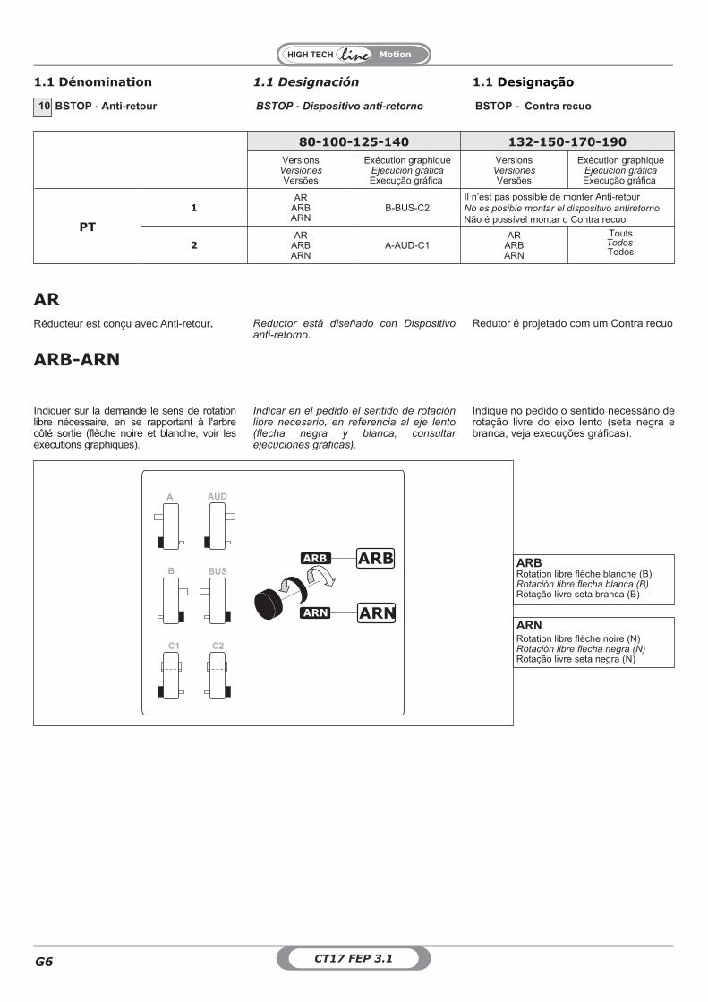
BSTOP - Anti-retour BSTOP - Dispositivo anti-retorno BSTOP - Contra recuo10
80-100-125-140 132-150-170-190
VersionsVersionesVersões
Exécution graphiqueEjecución gráficaExecução gráfica
VersionsVersionesVersões
Exécution graphiqueEjecución gráficaExecução gráfica
PT
1AR
ARBARN
B-BUS-C2
2AR
ARBARN
A-AUD-C1AR
ARBARN
ToutsTodosTodos
Il n’est pas possible de monter Anti-retourNo es posible montar el dispositivo antiretorno
Não é possível montar o Contra recuo
AR
ARB-ARN
1.1 Dénomination 1.1 Designación 1.1 Designação
Réducteur est conçu avec Anti-retour. Reductor está diseñado con Dispositivoanti-retorno.
Redutor é projetado com um Contra recuo
Indiquer sur la demande le sens de rotationlibre nécessaire, en se rapportant à l'arbrecôté sortie (flèche noire et blanche, voir lesexécutions graphiques).
Indicar en el pedido el sentido de rotaciónlibre necesario, en referencia al eje lento(flecha negra y blanca, consultarejecuciones gráficas).
Indique no pedido o sentido necessário derotação livre do eixo lento (seta negra ebranca, veja execuções gráficas).
ARBRotation libre flèche blanche (B)Rotación libre flecha blanca (B)Rotação livre seta branca (B)
ARNRotation libre flèche noire (N)Rotación libre flecha negra (N)Rotação livre seta negra (N)
A
B
C1 C2
AUD
BUS
ARB
ARN ARN
ARB
Motion
G
G7CT17 FEP 3.1
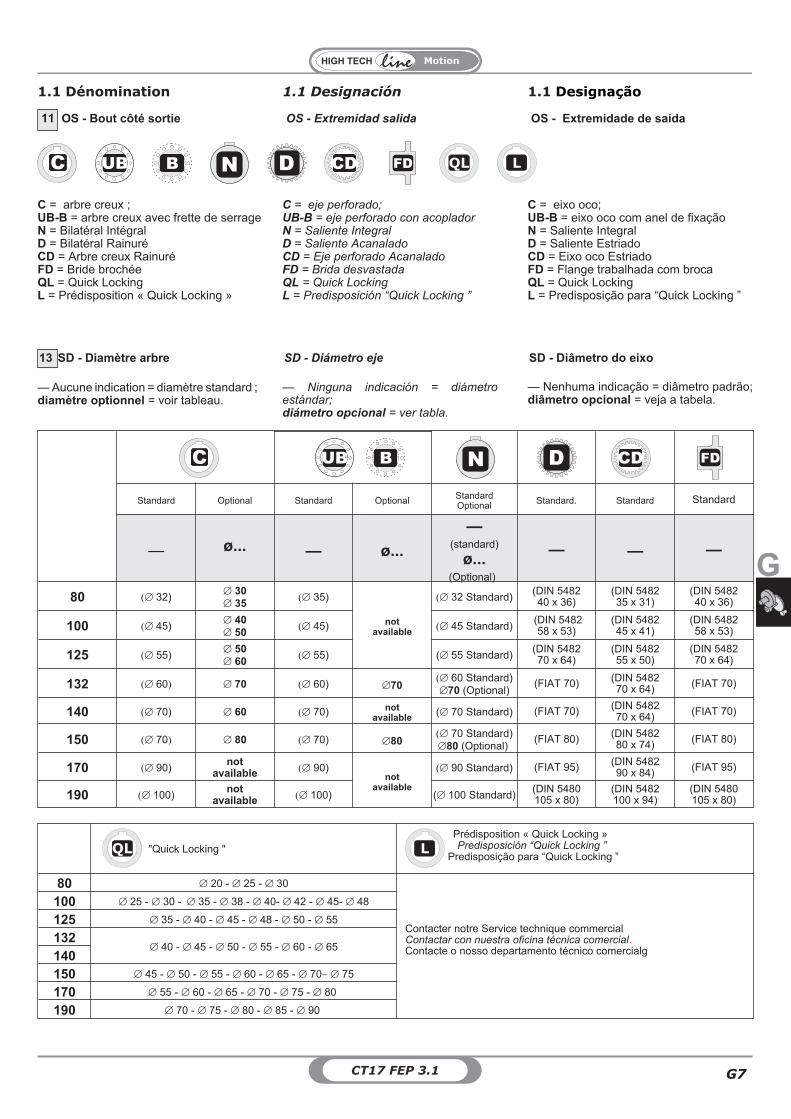
C = eje perforado;UB-B = eje perforado con acopladorN = Saliente IntegralD = Saliente AcanaladoCD = Eje perforado AcanaladoFD = Brida desvastadaQL = Quick LockingL = Predisposición “Quick Locking ”
C = eixo oco;UB-B = eixo oco com anel de fixaçãoN = Saliente IntegralD = Saliente EstriadoCD = Eixo oco EstriadoFD = Flange trabalhada com brocaQL = Quick LockingL = Predisposição para “Quick Locking ”
C = arbre creux ;UB-B = arbre creux avec frette de serrageN = Bilatéral IntégralD = Bilatéral RainuréCD = Arbre creux RainuréFD = Bride brochéeQL = Quick LockingL = Prédisposition « Quick Locking »
OS - Bout côté sortie OS - Extremidad salida OS - Extremidade de saída11
QL LC UBUB NN DD UBCD FDFDUBB
SD - Diámetro eje SD - Diâmetro do eixoSD - Diamètre arbre13
— Aucune indication = diamètre standard ;diamètre optionnel = voir tableau.
— Nenhuma indicação = diâmetro padrão;diâmetro opcional = veja a tabela.
— Ninguna indicación = diámetroestándar;diámetro opcional = ver tabla.
Standard Optional Standard Optional StandardOptional Standard. Standard Standard
— ø... — ø...
—(standard)
ø...(Optional)
— — —
80 �� 32)� 30� 35
�� 35)
notavailable
�� 32 Standard)(DIN 548240 x 36)
(DIN 548235 x 31)
(DIN 548240 x 36)
100 �� 45)� 40� 50
�� 45) �� 45 Standard)(DIN 548258 x 53)
(DIN 548245 x 41)
(DIN 548258 x 53)
125 �� 55)� 50� 60
�� 55) (� 55 Standard)(DIN 548270 x 64)
(DIN 548255 x 50)
(DIN 548270 x 64)
132 �� 60� � 70 �� 60) �70�� 60 Standard)�70 (Optional)
(FIAT 70) (DIN 548270 x 64) (FIAT 70)
140 �� 70) � 60 �� 70) notavailable
(� 70 Standard) (FIAT 70) (DIN 548270 x 64) (FIAT 70)
150 �� 70� � 80 �� 70) �80�� 70 Standard)�80 (Optional)
(FIAT 80) (DIN 548280 x 74) (FIAT 80)
170 �� 90)not
available �� 90)not
available
�� 90 Standard) (FIAT 95) (DIN 548290 x 84) (FIAT 95)
190 �� 100)not
available �� 100) (� 100 Standard)(DIN 5480105 x 80)
(DIN 5482100 x 94)
(DIN 5480105 x 80)
C UBUB UBB NN DD UBCD FDFD
QL "Quick Locking " LPrédisposition « Quick Locking »Predisposición “Quick Locking ”
Predisposição para “Quick Locking ”
Contacter notre Service technique commercialContactar con nuestra oficina técnica comercial.Contacte o nosso departamento técnico comercialg
80 � 20 - � 25 - � 30
100 � 25 - � 30 - � 35 - � 38 - � 40- � 42 - � 45- � 48
125 � 35 - � 40 - � 45 - � 48 - � 50 - � 55
132� 40 - � 45 - � 50 - � 55 - � 60 - � 65
140150 � 45 - � 50 - � 55 - � 60 - � 65 - � 70� � 75
170 � 55 - � 60 - � 65 - � 70 - � 75 - � 80
190 � 70 - � 75 - � 80 - � 85 - � 90
1.1 Dénomination 1.1 Designación 1.1 Designação
Motion
CT17 FEP 3.1G8
Bride de sortie:Pourvu toujours opposésdans cette configurationentrée.
Brida de salida:Siempre y siempre se opusoen esta configuraciónentrada.
Flange de saída:Desde sempre se opôsnesta configuraçãoentrada.
OF - Bride en sortie OF - Brida en salida OF - Flange de saída14
— F
Sans la Bride de sortieSin Brida de salida
Sem Flange de saída
Bride en sortie F. / Brida en salida F./ Flange de saída F.
voir pa. 1.9ver pa. 1.9veja pa.1.9
ACC1
PROT. Couvercle de protection Tapa de protección Cobertura de proteção
FF FF - Kit FF - Kit FF - Kit
RR Kit rondelle de montage Kit arandela de montaje Kit de anilha de montagem
ACC3 TEN Tendeur Tensor Tensor
voir section A-1.12ver secciòn A-1.12veja secçào A-1.12
OPT.OPT Matériau des bagues d'étanchéité Materiales de los anillos de estanqueidad Material dos anéis de vedação
OPT1 État de fourniture huile Estado suministro aceite Estado de fornecimento do óleo
OPT2 Peinture Pintura Pintura
1.1 Dénomination 1.1 Designación 1.1 Designação
AttentionIl n’est pas possible de monter la bride desortie avec le versions-AR ARB-ARN
AtenciónNo es posible montar la brida de salida,junto con la versiones-AR ARB-ARN
AtençãoNão é possível montar Flange de saída emconjunto com o versões ARB-AR-ARN
MP - Positions de montage MP - Posiciones de montaje MP - Posições de montagem15
[M2, M3, M4, M5, M6] Positions demontage avec indication des bouchons deniveau, de remplissage et de vidange ; saufautrement spécifié, la position M1 est àconsidérer standard (voir par. 1.4)
Montageposition [M2, M3, M4, M5, M6]Posições de montagem com a indicaçãodos tampos de nível, carga e descarga;caso não for especificado, considerepadrão a posição M1 (veja o par. 1.4)
[M2, M3, M4, M5, M6]Posiciones demontaje con indicaciones de los tapones denivel, carga y descarga; si no se especifica,se considera estándar la posición M1 (verpárr. 1.4)
16 OPT-ACC. - Options OPT-ACC - Optiones OPT-ACC. - Opçònes
Motion
G
G9CT17 FEP 3.1
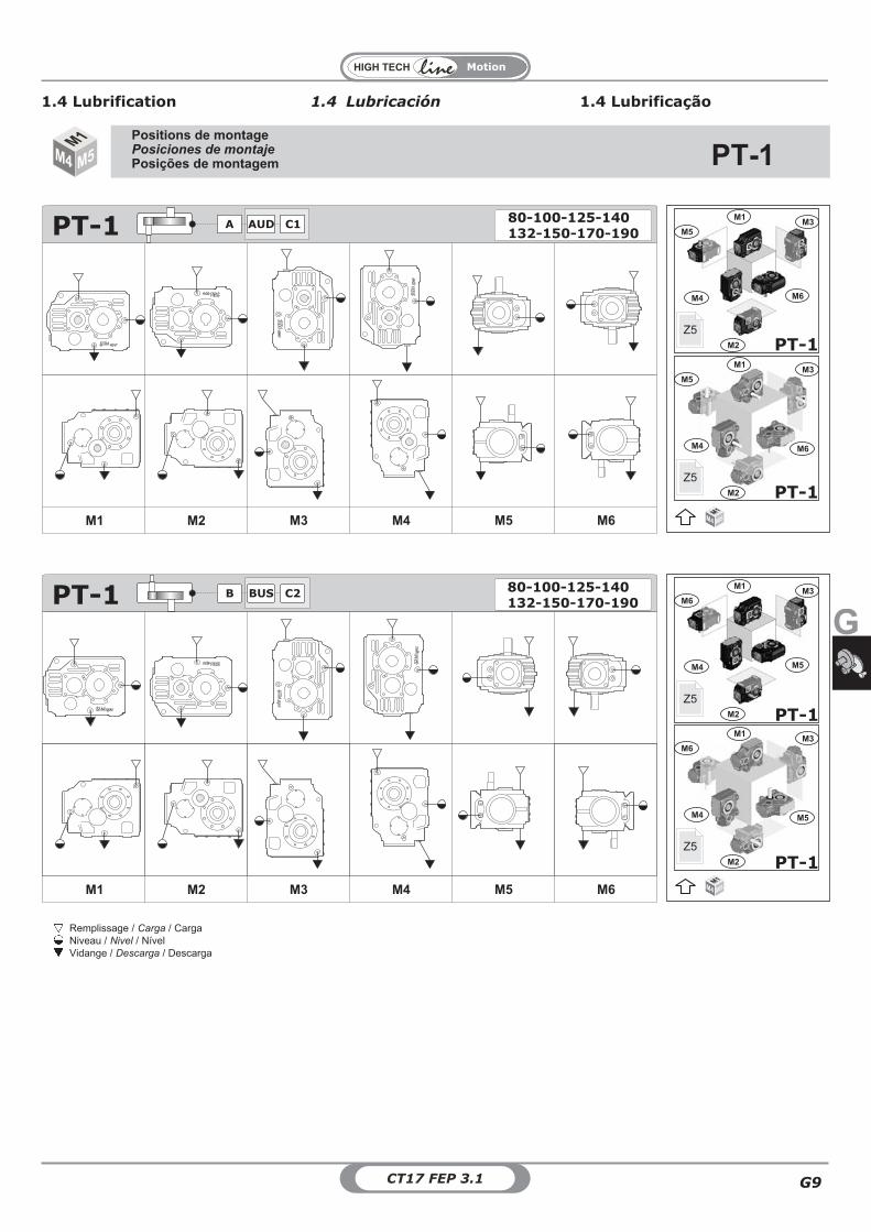
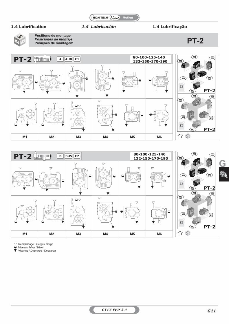
Positions de montagePosiciones de montajePosições de montagem
Remplissage / Carga / CargaNiveau / Nivel / NívelVidange / Descarga / Descarga
M3
M4
M5
M6
M1
M2 PT-1Z5
M2
M3
M4
M5
M6
M1
PT-1Z5
M1M4 M5
M3
M4
M6
M5
M1
M2 PT-1Z5
M3
M4
M6
M5
M1
M2 PT-1Z5
M1M4 M5
PT-1
1.4 Lubricación1.4 Lubrification 1.4 Lubrificação
M1 M2 M3 M4 M5 M6
PT-1 132-150-170-190AUDA C1
80-100-125-140
PT-1
M1 M2 M3 M4 M5 M6
B BUS C2132-150-170-19080-100-125-140
Motion
CT17 FEP 3.1G10
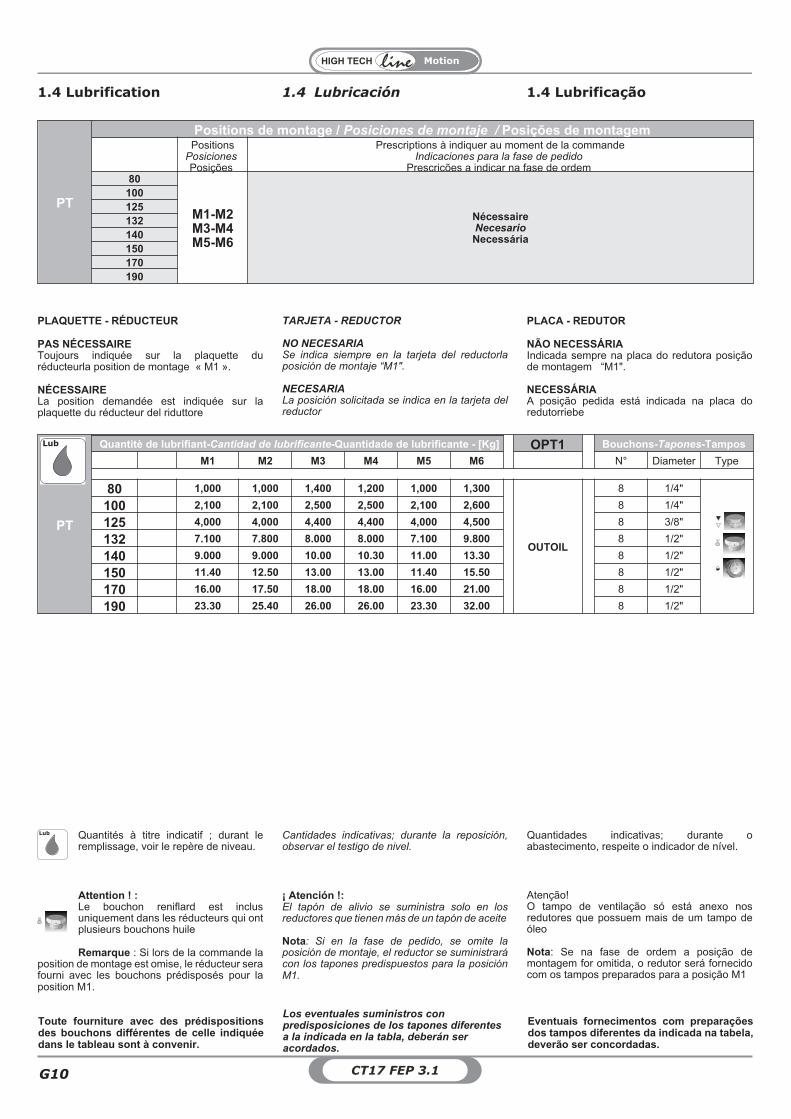
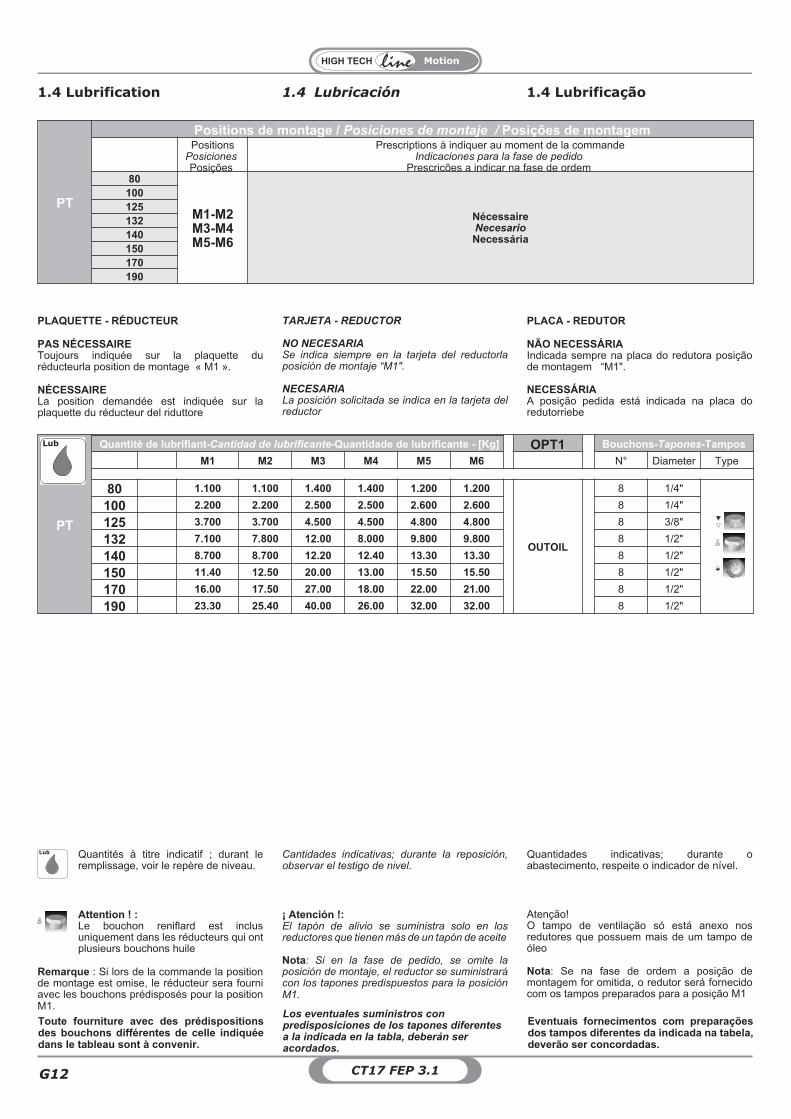
PT
Positions de montage / Posiciones de montaje / Posições de montagemPositions
PosicionesPosições
Prescriptions à indiquer au moment de la commandeIndicaciones para la fase de pedido
Prescrições a indicar na fase de ordem80
M1-M2M3-M4M5-M6
NécessaireNecesarioNecessária
100125132140150170190
PT
Quantitè de lubrifiant-Cantidad de lubrificante-Quantidade de lubrificante - [Kg] OPT1 Bouchons-Tapones-Tampos
M1 M2 M3 M4 M5 M6 N° Diameter Type
80 1,000 1,000 1,400 1,200 1,000 1,300
OUTOIL
8 1/4"
100 2,100 2,100 2,500 2,500 2,100 2,600 8 1/4"
125 4,000 4,000 4,400 4,400 4,000 4,500 8 3/8"
132 7.100 7.800 8.000 8.000 7.100 9.800 8 1/2"
140 9.000 9.000 10.00 10.30 11.00 13.30 8 1/2"
150 11.40 12.50 13.00 13.00 11.40 15.50 8 1/2"
170 16.00 17.50 18.00 18.00 16.00 21.00 8 1/2"
190 23.30 25.40 26.00 26.00 23.30 32.00 8 1/2"
Lub
Attention ! :Le bouchon reniflard est inclusuniquement dans les réducteurs qui ontplusieurs bouchons huile
Remarque : Si lors de la commande laposition de montage est omise, le réducteur serafourni avec les bouchons prédisposés pour laposition M1.
Quantités à titre indicatif ; durant leremplissage, voir le repère de niveau.
Lub
1.4 Lubricación1.4 Lubrification 1.4 Lubrificação
TARJETA - REDUCTOR
NO NECESARIASe indica siempre en la tarjeta del reductorlaposición de montaje “M1".
NECESARIALa posición solicitada se indica en la tarjeta delreductor
PLAQUETTE - RÉDUCTEUR
PAS NÉCESSAIREToujours indiquée sur la plaquette duréducteurla position de montage « M1 ».
NÉCESSAIRELa position demandée est indiquée sur laplaquette du réducteur del riduttore
PLACA - REDUTOR
NÃO NECESSÁRIAIndicada sempre na placa do redutora posiçãode montagem “M1".
NECESSÁRIAA posição pedida está indicada na placa doredutorriebe
Cantidades indicativas; durante la reposición,observar el testigo de nivel.
Quantidades indicativas; durante oabastecimento, respeite o indicador de nível.
¡ Atención !:El tapón de alivio se suministra solo en losreductores que tienen más de un tapón de aceite
Nota: Si en la fase de pedido, se omite laposición de montaje, el reductor se suministrarácon los tapones predispuestos para la posiciónM1.
Atenção!O tampo de ventilação só está anexo nosredutores que possuem mais de um tampo deóleo
Nota: Se na fase de ordem a posição demontagem for omitida, o redutor será fornecidocom os tampos preparados para a posição M1
Toute fourniture avec des prédispositionsdes bouchons différentes de celle indiquéedans le tableau sont à convenir.
Los eventuales suministros conpredisposiciones de los tapones diferentesa la indicada en la tabla, deberán seracordados.
Eventuais fornecimentos com preparaçõesdos tampos diferentes da indicada na tabela,deverão ser concordadas.
Motion
G
G11CT17 FEP 3.1
Positions de montagePosiciones de montajePosições de montagem
Remplissage / Carga / CargaNiveau / Nivel / NívelVidange / Descarga / Descarga
M3
M4
M5
M6
M1
M2 PT-2Z5
M3
M4
M5
M6
M1
M2 PT-2Z5
M1M4 M5
M3M6
M1
PT-2M2
M4 M5
Z5
M3
M5
M1
M2
M4
M6
PT-2Z5
M1M4 M5
PT-2
1.4 Lubricación1.4 Lubrification 1.4 Lubrificação
PT-2
M1 M2 M3 M4 M5 M6
AUDA C1132-150-170-19080-100-125-140
PT-2
M1 M2 M3 M4 M5 M6
B BUS C2132-150-170-19080-100-125-140
Motion
CT17 FEP 3.1G12
PT
Positions de montage / Posiciones de montaje / Posições de montagemPositions
PosicionesPosições
Prescriptions à indiquer au moment de la commandeIndicaciones para la fase de pedido
Prescrições a indicar na fase de ordem80
M1-M2M3-M4M5-M6
NécessaireNecesarioNecessária
100125132140150170190
PT
Quantitè de lubrifiant-Cantidad de lubrificante-Quantidade de lubrificante - [Kg] OPT1 Bouchons-Tapones-Tampos
M1 M2 M3 M4 M5 M6 N° Diameter Type
80 1.100 1.100 1.400 1.400 1.200 1.200
OUTOIL
8 1/4"
100 2.200 2.200 2.500 2.500 2.600 2.600 8 1/4"
125 3.700 3.700 4.500 4.500 4.800 4.800 8 3/8"
132 7.100 7.800 12.00 8.000 9.800 9.800 8 1/2"
140 8.700 8.700 12.20 12.40 13.30 13.30 8 1/2"
150 11.40 12.50 20.00 13.00 15.50 15.50 8 1/2"
170 16.00 17.50 27.00 18.00 22.00 21.00 8 1/2"
190 23.30 25.40 40.00 26.00 32.00 32.00 8 1/2"
Lub
1.4 Lubricación1.4 Lubrification 1.4 Lubrificação
TARJETA - REDUCTOR
NO NECESARIASe indica siempre en la tarjeta del reductorlaposición de montaje “M1".
NECESARIALa posición solicitada se indica en la tarjeta delreductor
PLAQUETTE - RÉDUCTEUR
PAS NÉCESSAIREToujours indiquée sur la plaquette duréducteurla position de montage « M1 ».
NÉCESSAIRELa position demandée est indiquée sur laplaquette du réducteur del riduttore
PLACA - REDUTOR
NÃO NECESSÁRIAIndicada sempre na placa do redutora posiçãode montagem “M1".
NECESSÁRIAA posição pedida está indicada na placa doredutorriebe
Attention ! :Le bouchon reniflard est inclusuniquement dans les réducteurs qui ontplusieurs bouchons huile
Remarque : Si lors de la commande la positionde montage est omise, le réducteur sera fourniavec les bouchons prédisposés pour la positionM1.
¡ Atención !:El tapón de alivio se suministra solo en losreductores que tienen más de un tapón de aceite
Nota: Si en la fase de pedido, se omite laposición de montaje, el reductor se suministrarácon los tapones predispuestos para la posiciónM1.
Atenção!O tampo de ventilação só está anexo nosredutores que possuem mais de um tampo deóleo
Nota: Se na fase de ordem a posição demontagem for omitida, o redutor será fornecidocom os tampos preparados para a posição M1
Toute fourniture avec des prédispositionsdes bouchons différentes de celle indiquéedans le tableau sont à convenir.
Los eventuales suministros conpredisposiciones de los tapones diferentesa la indicada en la tabla, deberán seracordados.
Eventuais fornecimentos com preparaçõesdos tampos diferentes da indicada na tabela,deverão ser concordadas.
Quantités à titre indicatif ; durant leremplissage, voir le repère de niveau.
Cantidades indicativas; durante la reposición,observar el testigo de nivel.
Quantidades indicativas; durante oabastecimento, respeite o indicador de nível.
Lub
Motion
G
G13CT17 FEP 3.1
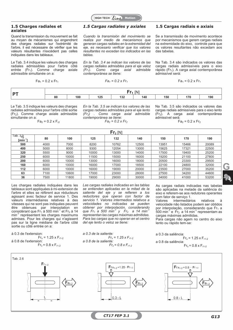
PT Fr1 [N]80 100 125 132 140 150 170 190
Tab. 3.5Fr2 [N]
n2
[min-1] 80 100 125 132 140 150 170 190
500 4000 7000 8200 10762 12500 13951 15466 20089400 5000 8000 9300 12054 13000 15625 17321 22500320 5500 9000 10000 13000 14000 17500 19400 25200250 6000 10000 11500 15000 16000 19200 21100 27800200 6000 10000 13000 16000 18000 20500 23300 29500160 6000 10000 16000 17000 18500 22100 24800 32000112 6000 10000 16000 19000 20000 23500 27000 3520063 7100 10600 17000 23000 28000 27500 34200 4460036 7500 11800 19000 29000 30000 34000 41000 53200
1.5 Cargas radiales y axiales1.5 Charges radiales etaxiales
1.5 Cargas radiais e axiais
Se a transmissão de movimento acontecepor mecanismos que gerem cargas radiaisna extremidade do eixo, controle para queos valores resultantes não excedam aosdas tabelas.
Na Tab. 3.4 são indicados os valores dascargas radiais admissíveis para o eixorápido (Fr1). A carga axial contemporâneaadmissível será:
Fa1 = 0.2 x Fr1
Cuando la transmisión del movimiento serealiza por medio de mecanismos quegeneran cargas radiales en la extremidad deleje, es necesario verificar que los valoresresultantes no excedan los indicados en lastablas.
En la Tab. 3.4 se indican los valores de lascargas radiales admisibles para el eje veloz(Fr1). Como carga axial admisiblecontemporánea se tiene:
Fa1 = 0.2 x Fr1
Quand la transmission du mouvement se faitau moyen de mécanismes qui engendrentdes charges radiales sur l'extrémité del'arbre, il est nécessaire de vérifier que lesvaleurs résultantes n'excèdent pas cellesindiquées dans les tableaux.
Le Tab. 3.4 indique les valeurs des chargesradiales admissibles pour l'arbre côtéentrée (Fr1). Comme charge axialeadmissible simultanée on a:
Fa1 = 0.2 x Fr1
En la Tab. 3.5 se indican los valores de lascargas radiales admisibles para el eje lento(Fr2) . Como carga axial admisiblecontemporánea se tiene:
Fa2 = 0.2 x Fr2
Na Tab. 3.5 são indicados os valores dascargas radiais admissíveis para o eixo lento(Fr2). A carga axial contemporâneaadmissível será:
Fa2 = 0.2 x Fr2
Le Tab. 3.5 indique les valeurs des chargesradiales admissibles pour l'arbre côté sortie(Fr2). Comme charge axiale admissiblesimultanée on a:
Fa2 = 0.2 x Fr2
Las cargas radiales indicadas en las tablasse entienden aplicadas en la mitad de lasaliente del eje y se refieren a losreductores que operan con factor deservicio 1. Valores intermedios relativos avelocidades no indicadas se puedenobtener por interpolación, considerandoque Fr1 a 500 min
-1y Fr2 a 14 min
-1
representan las cargas máximas admitidas.Para las cargas que no operan en el centrodel eje lento o veloz se tiene:
a 0.3 de la saliente:Frx = 1.25 x Fr1-2
a 0.8 de la saliente:Frx = 0.8 x Fr1-2
As cargas radiais indicadas nas tabelassão aplicadas na metade da saliência doeixo e referem-se aos redutores operantescom fator de serviço 1.Valores intermediários relativos àvelocidade não listados podem ser obtidospor interpolação, considerando que Fr1 a500 min-1 e Fr2 a 14 min-1 representam ascargas máximas admitidas.Para cargas não agem no centro do eixolento ou rápido tem-se:
a 0.3 da saliência:Frx = 1.25 x Fr1-2
a 0.8 da saliência:Frx = 0.8 x Fr1-2
Les charges radiales indiquées dans lestableaux sont appliquées à mi-extension del'arbre et elles se réfèrent aux réducteursagissant avec facteur de service 1. Desvaleurs intermédiaires relatives à desvitesses qui ne sont pas indiquées peuventêtre obtenues par interpolation enconsidérant que Fr1 à 500 min-1 et Fr2 à 14min-1 représentent les charges maximumsadmises. Pour les charges qui n'agissentpas sur la ligne médiane de l'arbre côtésortie ou côté entrée on a:
à 0.3 de l'extension:Frx = 1.25 x Fr1-2
à 0.8 de l'extension:Frx = 0.8 x Fr1-2
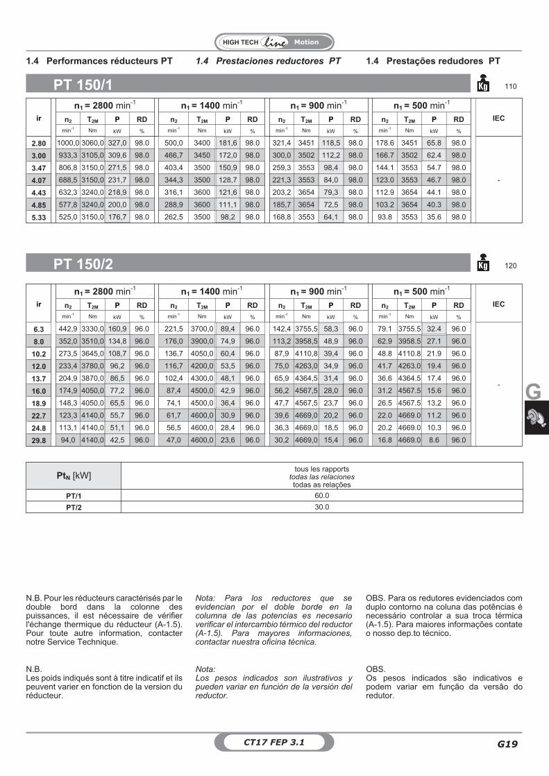
Tab. 2.6
Motion
CT17 FEP 3.1G14
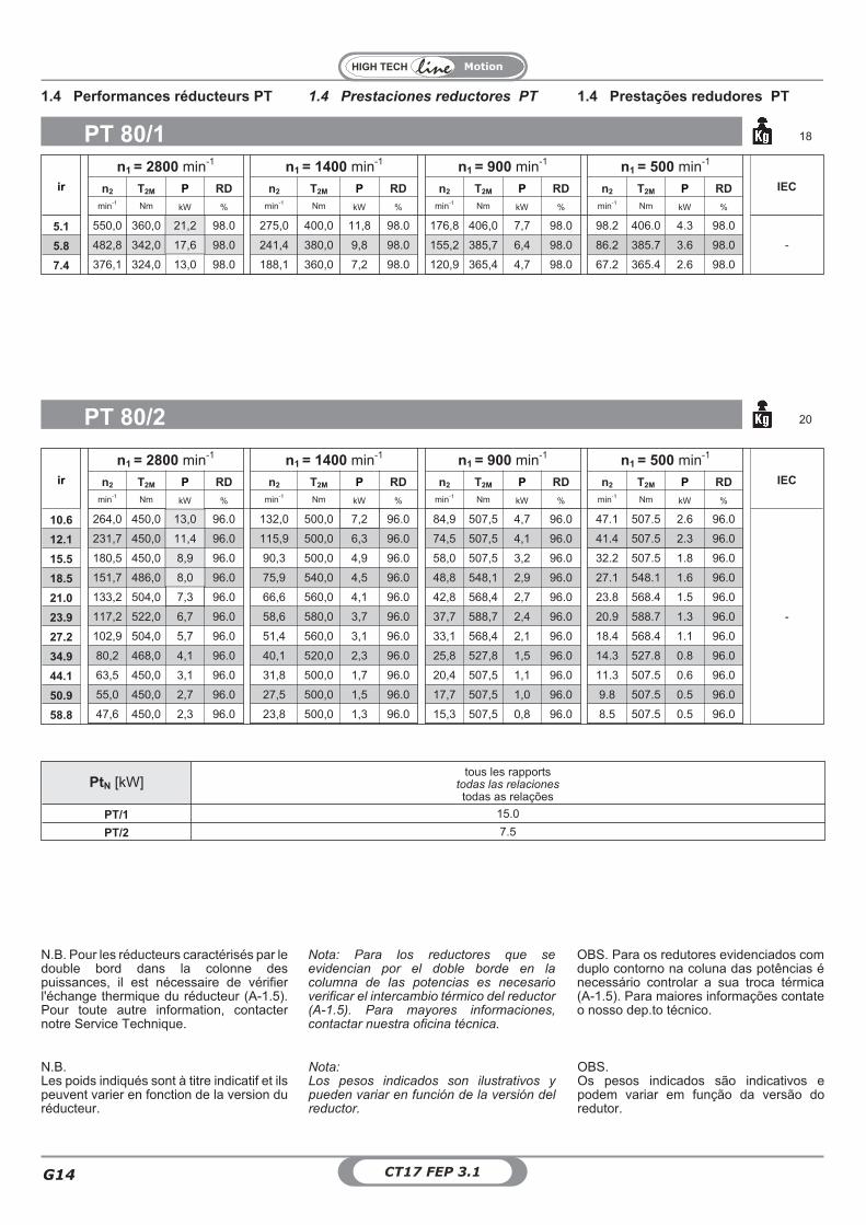
ir
n1 = 2800 min-1 n1 = 1400 min-1 n1 = 900 min-1 n1 = 500 min-1
IECn2 T2M P RD n2 T2M P RD n2 T2M P RD n2 T2M P RD
min-1 Nm kW % min-1 Nm kW % min-1 Nm kW % min-1 Nm kW %
5.1 550,0 360,0 21,2 98.0 275,0 400,0 11,8 98.0 176,8 406,0 7,7 98.0 98.2 406.0 4.3 98.0
-5.8 482,8 342,0 17,6 98.0 241,4 380,0 9,8 98.0 155,2 385,7 6,4 98.0 86.2 385.7 3.6 98.0
7.4 376,1 324,0 13,0 98.0 188,1 360,0 7,2 98.0 120,9 365,4 4,7 98.0 67.2 365.4 2.6 98.0
PT 80/1 18
ir
n1 = 2800 min-1 n1 = 1400 min-1 n1 = 900 min-1 n1 = 500 min-1
IECn2 T2M P RD n2 T2M P RD n2 T2M P RD n2 T2M P RD
min-1 Nm kW % min-1 Nm kW % min-1 Nm kW % min-1 Nm kW %
10.6 264,0 450,0 13,0 96.0 132,0 500,0 7,2 96.0 84,9 507,5 4,7 96.0 47.1 507.5 2.6 96.0
-
12.1 231,7 450,0 11,4 96.0 115,9 500,0 6,3 96.0 74,5 507,5 4,1 96.0 41.4 507.5 2.3 96.0
15.5 180,5 450,0 8,9 96.0 90,3 500,0 4,9 96.0 58,0 507,5 3,2 96.0 32.2 507.5 1.8 96.0
18.5 151,7 486,0 8,0 96.0 75,9 540,0 4,5 96.0 48,8 548,1 2,9 96.0 27.1 548.1 1.6 96.0
21.0 133,2 504,0 7,3 96.0 66,6 560,0 4,1 96.0 42,8 568,4 2,7 96.0 23.8 568.4 1.5 96.0
23.9 117,2 522,0 6,7 96.0 58,6 580,0 3,7 96.0 37,7 588,7 2,4 96.0 20.9 588.7 1.3 96.0
27.2 102,9 504,0 5,7 96.0 51,4 560,0 3,1 96.0 33,1 568,4 2,1 96.0 18.4 568.4 1.1 96.0
34.9 80,2 468,0 4,1 96.0 40,1 520,0 2,3 96.0 25,8 527,8 1,5 96.0 14.3 527.8 0.8 96.0
44.1 63,5 450,0 3,1 96.0 31,8 500,0 1,7 96.0 20,4 507,5 1,1 96.0 11.3 507.5 0.6 96.0
50.9 55,0 450,0 2,7 96.0 27,5 500,0 1,5 96.0 17,7 507,5 1,0 96.0 9.8 507.5 0.5 96.0
58.8 47,6 450,0 2,3 96.0 23,8 500,0 1,3 96.0 15,3 507,5 0,8 96.0 8.5 507.5 0.5 96.0
PT 80/2 20
PtN [kW]tous les rapports
todas las relacionestodas as relações
PT/1 15.0
PT/2 7.5
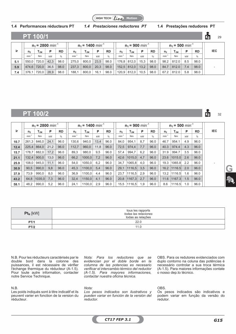
1.4 Prestaciones reductores PT 1.4 Prestações redudores PT1.4 Performances réducteurs PT
Nota:Los pesos indicados son ilustrativos ypueden variar en función de la versión delreductor.
OBS.Os pesos indicados são indicativos epodem variar em função da versão doredutor.
N.B.Les poids indiqués sont à titre indicatif et ilspeuvent varier en fonction de la version duréducteur.
Nota: Para los reductores que seevidencian por el doble borde en lacolumna de las potencias es necesarioverificar el intercambio térmico del reductor(A-1.5). Para mayores informaciones,contactar nuestra oficina técnica.
OBS. Para os redutores evidenciados comduplo contorno na coluna das potências énecessário controlar a sua troca térmica(A-1.5). Para maiores informações contateo nosso dep.to técnico.
N.B. Pour les réducteurs caractérisés par ledouble bord dans la colonne despuissances, il est nécessaire de vérifierl'échange thermique du réducteur (A-1.5).Pour toute autre information, contacternotre Service Technique.
Motion
G
G15CT17 FEP 3.1
ir
n1 = 2800 min-1 n1 = 1400 min-1 n1 = 900 min-1 n1 = 500 min-1
IECn2 T2M P RD n2 T2M P RD n2 T2M P RD n2 T2M P RD
min-1 Nm kW % min-1 Nm kW % min-1 Nm kW % min-1 Nm kW %
5.1 550,0 720,0 42,3 98.0 275,0 800,0 23,5 98.0 176,8 812,0 15,3 98.0 98.2 812.0 8.5 98.0
-5.9 474,6 720,0 36,5 98.0 237,3 800,0 20,3 98.0 152,5 812,0 13,2 98.0 84.7 812.0 7.4 98.0
7.4 376,1 720,0 28,9 98.0 188,1 800,0 16,1 98.0 120,9 812,0 10,5 98.0 67.2 812.0 5.8 98.0
PT 100/1 29
ir
n1 = 2800 min-1 n1 = 1400 min-1 n1 = 900 min-1 n1 = 500 min-1
IECn2 T2M P RD n2 T2M P RD n2 T2M P RD n2 T2M P RD
min-1 Nm kW % min-1 Nm kW % min-1 Nm kW % min-1 Nm kW %
10.7 261,3 846,0 24,1 96.0 130,6 940,0 13,4 96.0 84,0 954,1 8,7 96.0 46.7 954.1 4.9 96.0
-
12.4 225,4 864,0 21,2 96.0 112,7 960,0 11,8 96.0 72,5 974,4 7,7 96.0 40.3 974.4 4.3 96.0
15.7 178,7 882,0 17,2 96.0 89,3 980,0 9,5 96.0 57,4 994,7 6,2 96.0 31.9 994.7 3.5 96.0
21.1 132,4 900,0 13,0 96.0 66,2 1000,0 7,2 96.0 42,6 1015,0 4,7 96.0 23.6 1015.0 2.6 96.0
25.9 108,0 945,0 11,1 96.0 54,0 1050,0 6,2 96.0 34,7 1065,8 4,0 96.0 19.3 1065.8 2.2 96.0
30.9 90,5 990,0 9,8 96.0 45,3 1100,0 5,4 96.0 29,1 1116,5 3,5 96.0 16.2 1116.5 2.0 96.0
37.9 73,9 990,0 8,0 96.0 36,9 1100,0 4,4 96.0 23,7 1116,5 2,9 96.0 13.2 1116.5 1.6 96.0
43.2 64,8 1035,0 7,3 96.0 32,4 1150,0 4,1 96.0 20,8 1167,3 2,7 96.0 11.6 1167.3 1.5 96.0
58.1 48,2 990,0 5,2 96.0 24,1 1100,0 2,9 96.0 15,5 1116,5 1,9 96.0 8.6 1116.5 1.0 96.0
PT 100/2 32
PtN [kW]tous les rapports
todas las relacionestodas as relações
PT/1 22.0
PT/2 11.0
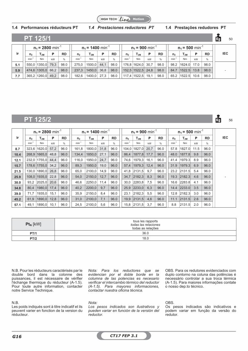
1.4 Prestaciones reductores PT 1.4 Prestações redudores PT1.4 Performances réducteurs PT
Nota:Los pesos indicados son ilustrativos ypueden variar en función de la versión delreductor.
OBS.Os pesos indicados são indicativos epodem variar em função da versão doredutor.
N.B.Les poids indiqués sont à titre indicatif et ilspeuvent varier en fonction de la version duréducteur.
Nota: Para los reductores que seevidencian por el doble borde en lacolumna de las potencias es necesarioverificar el intercambio térmico del reductor(A-1.5). Para mayores informaciones,contactar nuestra oficina técnica.
OBS. Para os redutores evidenciados comduplo contorno na coluna das potências énecessário controlar a sua troca térmica(A-1.5). Para maiores informações contateo nosso dep.to técnico.
N.B. Pour les réducteurs caractérisés par ledouble bord dans la colonne despuissances, il est nécessaire de vérifierl'échange thermique du réducteur (A-1.5).Pour toute autre information, contacternotre Service Technique.
Motion
CT17 FEP 3.1G16
ir
n1 = 2800 min-1 n1 = 1400 min-1 n1 = 900 min-1 n1 = 500 min-1
IECn2 T2M P RD n2 T2M P RD n2 T2M P RD n2 T2M P RD
min-1 Nm kW % min-1 Nm kW % min-1 Nm kW % min-1 Nm kW %
5.1 550,0 1350,0 79,3 98.0 275,0 1500,0 44,1 98.0 176,8 1624,0 30,7 98.0 98.2 1624.0 17.0 98.0
-5.9 474,6 1305,0 66,2 98.0 237,3 1450,0 36,8 98.0 152,5 1522,5 24,8 98.0 84.7 1522.5 13.8 98.0
7.7 365,2 1260,0 49,2 98.0 182,6 1400,0 27,3 98.0 117,4 1522,5 19,1 98.0 65.2 1522.5 10.6 98.0
PT 125/1 50
ir
n1 = 2800 min-1 n1 = 1400 min-1 n1 = 900 min-1 n1 = 500 min-1
IECn2 T2M P RD n2 T2M P RD n2 T2M P RD n2 T2M P RD
min-1 Nm kW % min-1 Nm kW % min-1 Nm kW % min-1 Nm kW %
8.7 323,6 1620,0 57,2 96.0 161,8 1800,0 31,8 96.0 104,0 1827,0 20,7 96.0 57.8 1827.0 11.5 96.0
-
10.4 268,9 1665,0 48,8 96.0 134,4 1850,0 27,1 96.0 86,4 1877,8 17,7 96.0 48.0 1877.8 9.8 96.0
12.1 232,0 1755,0 44,4 96.0 116,0 1950,0 24,7 96.0 74,6 1979,3 16,1 96.0 41.4 1979.3 8.9 96.0
15.7 178,6 1755,0 34,2 96.0 89,3 1950,0 19,0 96.0 57,4 1979,3 12,4 96.0 31.9 1979.3 6.9 96.0
21.5 130,0 1890,0 26,8 96.0 65,0 2100,0 14,9 96.0 41,8 2131,5 9,7 96.0 23.2 2131.5 5.4 96.0
25.9 108,0 1935,0 22,8 96.0 54,0 2150,0 12,7 96.0 34,7 2182,3 8,3 96.0 19.3 2182.3 4.6 96.0
30.0 93,2 2025,0 20,6 96.0 46,6 2250,0 11,4 96.0 30,0 2283,8 7,5 96.0 16.6 2283.8 4.1 96.0
34.8 80,4 1980,0 17,4 96.0 40,2 2200,0 9,7 96.0 25,9 2233,0 6,3 96.0 14.4 2233.0 3.5 96.0
39.0 71,7 1935,0 15,1 96.0 35,9 2150,0 8,4 96.0 23,1 2182,3 5,5 96.0 12.8 2182.3 3.0 96.0
45.2 61,9 1890,0 12,8 96.0 31,0 2100,0 7,1 96.0 19,9 2131,5 4,6 96.0 11.1 2131.5 2.6 96.0
57.1 49,1 1890,0 10,1 96.0 24,5 2100,0 5,6 96.0 15,8 2131,5 3,7 96.0 8.8 2131.5 2.0 96.0
PT 125/2 56
PtN [kW]tous les rapports
todas las relacionestodas as relações
PT/1 36.0
PT/2 18.0
1.4 Prestaciones reductores PT 1.4 Prestações redudores PT1.4 Performances réducteurs PT
Nota:Los pesos indicados son ilustrativos ypueden variar en función de la versión delreductor.
OBS.Os pesos indicados são indicativos epodem variar em função da versão doredutor.
N.B.Les poids indiqués sont à titre indicatif et ilspeuvent varier en fonction de la version duréducteur.
Nota: Para los reductores que seevidencian por el doble borde en lacolumna de las potencias es necesarioverificar el intercambio térmico del reductor(A-1.5). Para mayores informaciones,contactar nuestra oficina técnica.
OBS. Para os redutores evidenciados comduplo contorno na coluna das potências énecessário controlar a sua troca térmica(A-1.5). Para maiores informações contateo nosso dep.to técnico.
N.B. Pour les réducteurs caractérisés par ledouble bord dans la colonne despuissances, il est nécessaire de vérifierl'échange thermique du réducteur (A-1.5).Pour toute autre information, contacternotre Service Technique.
Motion
G
G17CT17 FEP 3.1
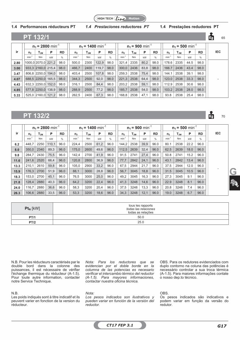
ir
n1 = 2800 min-1 n1 = 1400 min-1 n1 = 900 min-1 n1 = 500 min-1
IECn2 T2M P RD n2 T2M P RD n2 T2M P RD n2 T2M P RD
min-1 Nm kW % min-1 Nm kW % min-1 Nm kW % min-1 Nm kW %
2.80 1000,0 2070,0 221,2 98.0 500,0 2300 122,9 98.0 321,4 2335 80,2 98.0 178.6 2335 44.5 98.0
-
3.00 933,3 2160,0 215,4 98.0 466,7 2400 119,7 98.0 300,0 2436 83,8 98.0 166.7 2436 43.4 98.0
3.47 806,8 2250,0 194,0 98.0 403,4 2500 107,8 98.0 259,3 2538 75,4 98.0 144.1 2538 39.1 98.0
4.07 688,5 2250,0 165,5 98.0 344,3 2500 92,0 98.0 221,3 2538 64,4 98.0 123.0 2538 33.3 98.0
4.43 632,3 2250,0 152,0 98.0 316,1 2500 84,4 98.0 203,2 2538 59,1 98.0 112.9 2538 30.6 98.0
4.85 577,8 2250,0 138,9 98.0 288,9 2500 77,2 98.0 185,7 2538 54,0 98.0 103.2 2538 28.0 98.0
5.33 525,0 2160,0 121,2 98.0 262,5 2400 67,3 98.0 168,8 2538 47,1 98.0 93.8 2538 25.4 98.0
PT 132/1 65
ir
n1 = 2800 min-1 n1 = 1400 min-1 n1 = 900 min-1 n1 = 500 min-1
IECn2 T2M P RD n2 T2M P RD n2 T2M P RD n2 T2M P RD
min-1 Nm kW % min-1 Nm kW % min-1 Nm kW % min-1 Nm kW %
6.2 448,7 2250 110,1 96.0 224,4 2500 61,2 96.0 144,2 2538 39,9 96.0 80.1 2538 22.2 96.0
-
8.0 350,0 2340 89,3 96.0 175,0 2600 49,6 96.0 112,5 2639 32,4 96.0 62.5 2639 18.0 96.0
9.8 284,7 2430 75,5 96.0 142,4 2700 41,9 96.0 91,5 2741 27,4 96.0 50.8 2741 15.2 96.0
11.6 241,6 2520 66,4 96.0 120,8 2800 36,9 96.0 77,7 2842 24,1 96.0 43.1 2842 13.4 96.0
13.3 210,1 2610 59,8 96.0 105,0 2900 33,2 96.0 67,5 2944 21,7 96.0 37.5 2944 12.0 96.0
15.9 176,3 2700 51,9 96.0 88,1 3000 28,8 96.0 56,7 3045 18,8 96.0 31.5 3045 10.5 96.0
18.3 153,0 2700 45,1 96.0 76,5 3000 25,0 96.0 49,2 3045 16,3 96.0 27.3 3045 9.1 96.0
21.8 128,4 2880 40,3 96.0 64,2 3200 22,4 96.0 41,3 3248 14,6 96.0 22.9 3248 8.1 96.0
24.0 116,7 2880 36,6 96.0 58,3 3200 20,4 96.0 37,5 3248 13,3 96.0 20.8 3248 7.4 96.0
26.3 106,6 2880 33,5 96.0 53,3 3200 18,6 96.0 34,3 3248 12,1 96.0 19.0 3248 6.7 96.0
PT 132/2 70
PtN [kW]tous les rapports
todas las relacionestodas as relações
PT/1 50.0
PT/2 25.0
1.4 Prestaciones reductores PT 1.4 Prestações redudores PT1.4 Performances réducteurs PT
Nota:Los pesos indicados son ilustrativos ypueden variar en función de la versión delreductor.
OBS.Os pesos indicados são indicativos epodem variar em função da versão doredutor.
N.B.Les poids indiqués sont à titre indicatif et ilspeuvent varier en fonction de la version duréducteur.
Nota: Para los reductores que seevidencian por el doble borde en lacolumna de las potencias es necesarioverificar el intercambio térmico del reductor(A-1.5). Para mayores informaciones,contactar nuestra oficina técnica.
OBS. Para os redutores evidenciados comduplo contorno na coluna das potências énecessário controlar a sua troca térmica(A-1.5). Para maiores informações contateo nosso dep.to técnico.
N.B. Pour les réducteurs caractérisés par ledouble bord dans la colonne despuissances, il est nécessaire de vérifierl'échange thermique du réducteur (A-1.5).Pour toute autre information, contacternotre Service Technique.
Motion
CT17 FEP 3.1G18
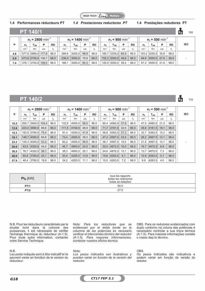
ir
n1 = 2800 min-1 n1 = 1400 min-1 n1 = 900 min-1 n1 = 500 min-1
IECn2 T2M P RD n2 T2M P RD n2 T2M P RD n2 T2M P RD
min-1 Nm kW % min-1 Nm kW % min-1 Nm kW % min-1 Nm kW %
4.8 577,8 2880,0 177,8 98.0 288,9 3200,0 98,8 98.0 185,7 3250,0 64,5 98.0 103.2 3250.0 35.8 98.0
-5.9 473,8 2700,0 136,7 98.0 236,9 3000,0 75,9 98.0 152,3 3050,0 49,6 98.0 84.6 3050.0 27.6 98.0
7.4 376,1 2700,0 108,5 98.0 188,1 3000,0 60,3 98.0 120,9 3050,0 39,4 98.0 67.2 3050.0 21.9 98.0
PT 140/1 100
ir
n1 = 2800 min-1 n1 = 1400 min-1 n1 = 900 min-1 n1 = 500 min-1
IECn2 T2M P RD n2 T2M P RD n2 T2M P RD n2 T2M P RD
min-1 Nm kW % min-1 Nm kW % min-1 Nm kW % min-1 Nm kW %
10.5 265,7 3600,0 104,4 96.0 132,9 4000,0 58,0 96.0 85,4 4060,0 37,8 96.0 47.5 4060.0 21.0 96.0
-
12.6 223,0 3690,0 89,8 96.0 111,5 4100,0 49,9 96.0 71,7 4161,5 32,5 96.0 39.8 4161.5 18.1 96.0
15.3 182,9 3780,0 75,4 96.0 91,4 4200,0 41,9 96.0 58,8 4263,0 27,3 96.0 32.7 4263.0 15.2 96.0
19.1 146,7 4050,0 64,8 96.0 73,4 4500,0 36,0 96.0 47,2 4567,5 23,5 96.0 26.2 4567.5 13.1 96.0
23.3 120,3 4050,0 53,2 96.0 60,2 4500,0 29,5 96.0 38,7 4567,5 19,3 96.0 21.5 4567.5 10.7 96.0
30.0 93,5 4320,0 44,0 96.0 46,7 4800,0 24,5 96.0 30,0 4872,0 16,0 96.0 16.7 4872.0 8.9 96.0
36.5 76,7 4320,0 36,1 96.0 38,3 4800,0 20,1 96.0 24,6 4872,0 13,1 96.0 13.7 4872.0 7.3 96.0
46.0 60,8 3780,0 25,1 96.0 30,4 4200,0 13,9 96.0 19,6 4263,0 9,1 96.0 10.9 4263.0 5.1 96.0
57.9 48,4 3780,0 19,9 96.0 24,2 4200,0 11,1 96.0 15,5 4263,0 7,2 96.0 8.6 4263.0 4.0 96.0
PT 140/2 110
PtN [kW]tous les rapports
todas las relacionestodas as relações
PT/1 54.0
PT/2 27.0
1.4 Prestaciones reductores PT 1.4 Prestações redudores PT1.4 Performances réducteurs PT
Nota:Los pesos indicados son ilustrativos ypueden variar en función de la versión delreductor.
OBS.Os pesos indicados são indicativos epodem variar em função da versão doredutor.
N.B.Les poids indiqués sont à titre indicatif et ilspeuvent varier en fonction de la version duréducteur.
Nota: Para los reductores que seevidencian por el doble borde en lacolumna de las potencias es necesarioverificar el intercambio térmico del reductor(A-1.5). Para mayores informaciones,contactar nuestra oficina técnica.
OBS. Para os redutores evidenciados comduplo contorno na coluna das potências énecessário controlar a sua troca térmica(A-1.5). Para maiores informações contateo nosso dep.to técnico.
N.B. Pour les réducteurs caractérisés par ledouble bord dans la colonne despuissances, il est nécessaire de vérifierl'échange thermique du réducteur (A-1.5).Pour toute autre information, contacternotre Service Technique.
Motion
G
G19CT17 FEP 3.1
ir
n1 = 2800 min-1 n1 = 1400 min-1 n1 = 900 min-1 n1 = 500 min-1
IECn2 T2M P RD n2 T2M P RD n2 T2M P RD n2 T2M P RD
min-1 Nm kW % min-1 Nm kW % min-1 Nm kW % min-1 Nm kW %
2.80 1000,0 3060,0 327,0 98.0 500,0 3400 181,6 98.0 321,4 3451 118,5 98.0 178.6 3451 65.8 98.0
-
3.00 933,3 3105,0 309,6 98.0 466,7 3450 172,0 98.0 300,0 3502 112,2 98.0 166.7 3502 62.4 98.0
3.47 806,8 3150,0 271,5 98.0 403,4 3500 150,9 98.0 259,3 3553 98,4 98.0 144.1 3553 54.7 98.0
4.07 688,5 3150,0 231,7 98.0 344,3 3500 128,7 98.0 221,3 3553 84,0 98.0 123.0 3553 46.7 98.0
4.43 632,3 3240,0 218,9 98.0 316,1 3600 121,6 98.0 203,2 3654 79,3 98.0 112.9 3654 44.1 98.0
4.85 577,8 3240,0 200,0 98.0 288,9 3600 111,1 98.0 185,7 3654 72,5 98.0 103.2 3654 40.3 98.0
5.33 525,0 3150,0 176,7 98.0 262,5 3500 98,2 98.0 168,8 3553 64,1 98.0 93.8 3553 35.6 98.0
PT 150/1 110
PT 150/2 120
ir
n1 = 2800 min-1 n1 = 1400 min-1 n1 = 900 min-1 n1 = 500 min-1
IECn2 T2M P RD n2 T2M P RD n2 T2M P RD n2 T2M P RD
min-1 Nm kW % min-1 Nm kW % min-1 Nm kW % min-1 Nm kW %
6.3 442,9 3330,0 160,9 96.0 221,5 3700,0 89,4 96.0 142,4 3755,5 58,3 96.0 79.1 3755.5 32.4 96.0
-
8.0 352,0 3510,0 134,8 96.0 176,0 3900,0 74,9 96.0 113,2 3958,5 48,9 96.0 62.9 3958.5 27.1 96.0
10.2 273,5 3645,0 108,7 96.0 136,7 4050,0 60,4 96.0 87,9 4110,8 39,4 96.0 48.8 4110.8 21.9 96.0
12.0 233,4 3780,0 96,2 96.0 116,7 4200,0 53,5 96.0 75,0 4263,0 34,9 96.0 41.7 4263.0 19.4 96.0
13.7 204,9 3870,0 86,5 96.0 102,4 4300,0 48,1 96.0 65,9 4364,5 31,4 96.0 36.6 4364.5 17.4 96.0
16.0 174,9 4050,0 77,2 96.0 87,4 4500,0 42,9 96.0 56,2 4567,5 28,0 96.0 31.2 4567.5 15.6 96.0
18.9 148,3 4050,0 65,5 96.0 74,1 4500,0 36,4 96.0 47,7 4567,5 23,7 96.0 26.5 4567.5 13.2 96.0
22.7 123,3 4140,0 55,7 96.0 61,7 4600,0 30,9 96.0 39,6 4669,0 20,2 96.0 22.0 4669.0 11.2 96.0
24.8 113,1 4140,0 51,1 96.0 56,5 4600,0 28,4 96.0 36,3 4669,0 18,5 96.0 20.2 4669.0 10.3 96.0
29.8 94,0 4140,0 42,5 96.0 47,0 4600,0 23,6 96.0 30,2 4669,0 15,4 96.0 16.8 4669.0 8.6 96.0
PtN [kW]tous les rapports
todas las relacionestodas as relações
PT/1 60.0
PT/2 30.0
1.4 Prestaciones reductores PT 1.4 Prestações redudores PT1.4 Performances réducteurs PT
Nota:Los pesos indicados son ilustrativos ypueden variar en función de la versión delreductor.
OBS.Os pesos indicados são indicativos epodem variar em função da versão doredutor.
N.B.Les poids indiqués sont à titre indicatif et ilspeuvent varier en fonction de la version duréducteur.
Nota: Para los reductores que seevidencian por el doble borde en lacolumna de las potencias es necesarioverificar el intercambio térmico del reductor(A-1.5). Para mayores informaciones,contactar nuestra oficina técnica.
OBS. Para os redutores evidenciados comduplo contorno na coluna das potências énecessário controlar a sua troca térmica(A-1.5). Para maiores informações contateo nosso dep.to técnico.
N.B. Pour les réducteurs caractérisés par ledouble bord dans la colonne despuissances, il est nécessaire de vérifierl'échange thermique du réducteur (A-1.5).Pour toute autre information, contacternotre Service Technique.
Motion
CT17 FEP 3.1G20
ir
n1 = 2800 min-1 n1 = 1400 min-1 n1 = 900 min-1 n1 = 500 min-1
IECn2 T2M P RD n2 T2M P RD n2 T2M P RD n2 T2M P RD
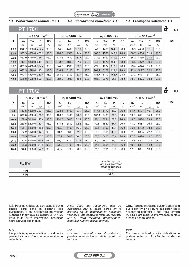
min-1 Nm kW % min-1 Nm kW % min-1 Nm kW % min-1 Nm kW %
2.62 1069,1 3960,0 452,4 98.0 534,5 4400 251,3 98.0 343,6 4466 164,0 98.0 190.9 4466 91.1 98.0
-
3.00 933,3 4050,0 403,9 98.0 466,7 4500 224,4 98.0 300,0 4568 146,4 98.0 166.7 4568 81.3 98.0
3.22 869,0 4140,0 384,4 98.0 434,5 4600 213,6 98.0 279,3 4669 139,3 98.0 155.2 4669 77.4 98.0
3.75 746,7 4320,0 344,7 98.0 373,3 4800 191,5 98.0 240,0 4872 124,9 98.0 133.3 4872 69.4 98.0
4.07 688,5 4410,0 324,4 98.0 344,3 4900 180,2 98.0 221,3 4974 117,6 98.0 123.0 4974 65.3 98.0
4.43 632,3 4590,0 310,1 98.0 316,1 5100 172,3 98.0 203,2 5177 112,4 98.0 112.9 5177 62.4 98.0
4.85 577,8 4590,0 283,4 98.0 288,9 5100 157,4 98.0 185,7 5177 102,7 98.0 103.2 5177 57.1 98.0
5.33 525,0 4500,0 252,4 98.0 262,5 5000 140,2 98.0 168,8 5075 91,5 98.0 93.8 5075 50.8 98.0
PT 170/1 174
PT 170/2 184
ir
n1 = 2800 min-1 n1 = 1400 min-1 n1 = 900 min-1 n1 = 500 min-1
IECn2 T2M P RD n2 T2M P RD n2 T2M P RD n2 T2M P RD
min-1 Nm kW % min-1 Nm kW % min-1 Nm kW % min-1 Nm kW %
6.1 457,5 4590,0 229,1 96.0 228,8 5100 127,3 96.0 147,1 5177 83,0 96.0 81.7 5177 46.1 96.0
-
8.4 333,3 4860,0 176,7 96.0 166,7 5400 98,2 96.0 107,1 5481 64,1 96.0 59.5 5481 35.6 96.0
10.4 268,9 5040,0 147,8 96.0 134,5 5600 82,1 96.0 86,4 5684 53,6 96.0 48.0 5684 29.8 96.0
12.2 229,5 5220,0 130,7 96.0 114,8 5800 72,6 96.0 73,8 5887 47,4 96.0 41.0 5887 26.3 96.0
14.1 198,4 5490,0 118,8 96.0 99,2 6100 66,0 96.0 63,8 6192 43,1 96.0 35.4 6192 23.9 96.0
15.4 182,2 5670,0 112,7 96.0 91,1 6300 62,6 96.0 58,6 6395 40,8 96.0 32.5 6395 22.7 96.0
18.0 155,5 5760,0 97,7 96.0 77,7 6400 54,3 96.0 50,0 6496 35,4 96.0 27.8 6496 19.7 96.0
21.5 130,5 6030,0 85,8 96.0 65,2 6700 47,7 96.0 41,9 6801 31,1 96.0 23.3 6801 17.3 96.0
25.8 108,3 6030,0 71,3 96.0 54,2 6700 39,6 96.0 34,8 6801 25,8 96.0 19.3 6801 14.3 96.0
28.4 98,4 6030,0 64,7 96.0 49,2 6700 36,0 96.0 31,6 6801 23,5 96.0 17.6 6801 13.0 96.0
PtN [kW]tous les rapports
todas las relacionestodas as relações
PT/1 74.0
PT/2 37.0
1.4 Prestaciones reductores PT 1.4 Prestações redudores PT1.4 Performances réducteurs PT
Nota:Los pesos indicados son ilustrativos ypueden variar en función de la versión delreductor.
OBS.Os pesos indicados são indicativos epodem variar em função da versão doredutor.
N.B.Les poids indiqués sont à titre indicatif et ilspeuvent varier en fonction de la version duréducteur.
Nota: Para los reductores que seevidencian por el doble borde en lacolumna de las potencias es necesarioverificar el intercambio térmico del reductor(A-1.5). Para mayores informaciones,contactar nuestra oficina técnica.
OBS. Para os redutores evidenciados comduplo contorno na coluna das potências énecessário controlar a sua troca térmica(A-1.5). Para maiores informações contateo nosso dep.to técnico.
N.B. Pour les réducteurs caractérisés par ledouble bord dans la colonne despuissances, il est nécessaire de vérifierl'échange thermique du réducteur (A-1.5).Pour toute autre information, contacternotre Service Technique.
Motion
G
G21CT17 FEP 3.1
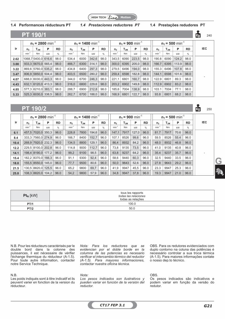
ir
n1 = 2800 min-1 n1 = 1400 min-1 n1 = 900 min-1 n1 = 500 min-1
IECn2 T2M P RD n2 T2M P RD n2 T2M P RD n2 T2M P RD
min-1 Nm kW % min-1 Nm kW % min-1 Nm kW % min-1 Nm kW %
2.62 1068,7 5400,0 616,6 98.0 534,4 6000 342,6 98.0 343,5 6090 223,5 98.0 190.8 6090 124.2 98.0
-
3.00 933,3 5670,0 565,4 98.0 466,7 6300 314,1 98.0 300,0 6395 205,0 98.0 166.7 6395 113.9 98.0
3.22 869,6 5760,0 535,2 98.0 434,8 6400 297,3 98.0 279,5 6496 194,0 98.0 155.3 6496 107.8 98.0
3.47 806,9 5850,0 504,4 98.0 403,5 6500 280,2 98.0 259,4 6598 182,8 98.0 144.1 6598 101.6 98.0
4.07 688,0 6030,0 443,3 98.0 344,0 6700 246,3 98.0 221,1 6801 160,7 98.0 122.9 6801 89.3 98.0
4.43 632,1 6120,0 413,3 98.0 316,0 6800 229,6 98.0 203,2 6902 149,8 98.0 112.9 6902 83.2 98.0
4.85 577,3 6210,0 383,1 98.0 288,7 6900 212,8 98.0 185,6 7004 138,9 98.0 103.1 7004 77.1 98.0
5.33 525,3 6030,0 338,5 98.0 262,7 6700 188,0 98.0 168,9 6801 122,7 98.0 93.8 6801 68.2 98.0
PT 190/1 240
PT 190/2 250
ir
n1 = 2800 min-1 n1 = 1400 min-1 n1 = 900 min-1 n1 = 500 min-1
IECn2 T2M P RD n2 T2M P RD n2 T2M P RD n2 T2M P RD
min-1 Nm kW % min-1 Nm kW % min-1 Nm kW % min-1 Nm kW %
6.1 457,5 7020,0 350,3 96.0 228,8 7800 194,6 96.0 147,1 7917 127,0 96.0 81.7 7917 70.6 96.0
-
8.4 333,3 7560,0 274,9 96.0 166,7 8400 152,7 96.0 107,1 8526 99,6 96.0 59.5 8526 55.4 96.0
10.4 268,9 7920,0 232,3 96.0 134,5 8800 129,1 96.0 86,4 8932 84,2 96.0 48.0 8932 46.8 96.0
12.2 229,5 8100,0 202,8 96.0 114,8 9000 112,7 96.0 73,8 9135 73,5 96.0 41.0 9135 40.8 96.0
14.1 198,4 8190,0 177,2 96.0 99,2 9100 98,5 96.0 63,8 9237 64,2 96.0 35.4 9237 35.7 96.0
15.4 182,2 8370,0 166,3 96.0 91,1 9300 92,4 96.0 58,6 9440 60,3 96.0 32.5 9440 33.5 96.0
18.0 155,5 8550,0 145,0 96.0 77,7 9500 80,6 96.0 50,0 9643 52,6 96.0 27.8 9643 29.2 96.0
21.5 130,5 8820,0 125,5 96.0 65,2 9800 69,7 96.0 41,9 9947 45,5 96.0 23.3 9947 25.3 96.0
25.8 108,3 8820,0 104,2 96.0 54,2 9800 57,9 96.0 34,8 9947 37,8 96.0 19.3 9947 21.0 96.0
PtN [kW]tous les rapports
todas las relacionestodas as relações
PT/1 100.0
PT/2 50.0
1.4 Prestaciones reductores PT 1.4 Prestações redudores PT1.4 Performances réducteurs PT
Nota:Los pesos indicados son ilustrativos ypueden variar en función de la versión delreductor.
OBS.Os pesos indicados são indicativos epodem variar em função da versão doredutor.
N.B.Les poids indiqués sont à titre indicatif et ilspeuvent varier en fonction de la version duréducteur.
Nota: Para los reductores que seevidencian por el doble borde en lacolumna de las potencias es necesarioverificar el intercambio térmico del reductor(A-1.5). Para mayores informaciones,contactar nuestra oficina técnica.
OBS. Para os redutores evidenciados comduplo contorno na coluna das potências énecessário controlar a sua troca térmica(A-1.5). Para maiores informações contateo nosso dep.to técnico.
N.B. Pour les réducteurs caractérisés par ledouble bord dans la colonne despuissances, il est nécessaire de vérifierl'échange thermique du réducteur (A-1.5).Pour toute autre information, contacternotre Service Technique.
Motion
CT17 FEP 3.1G22
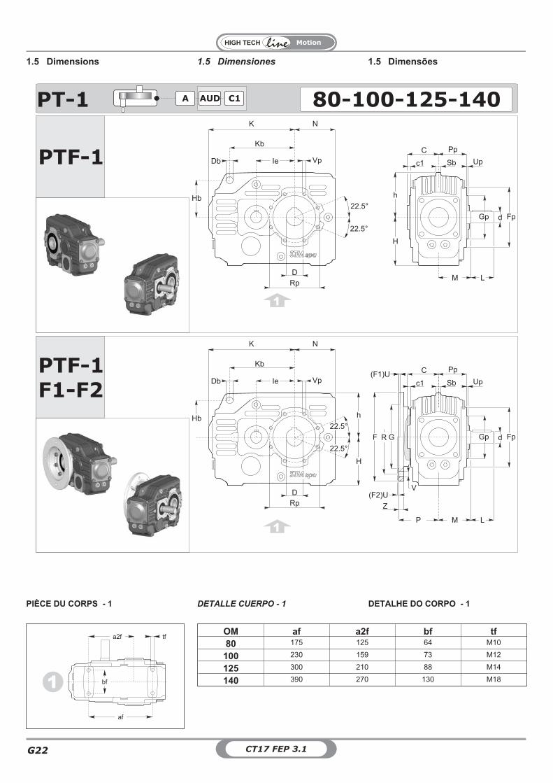
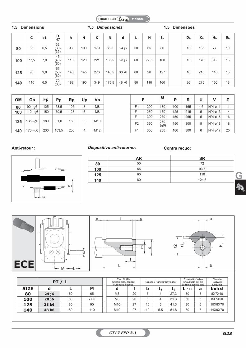
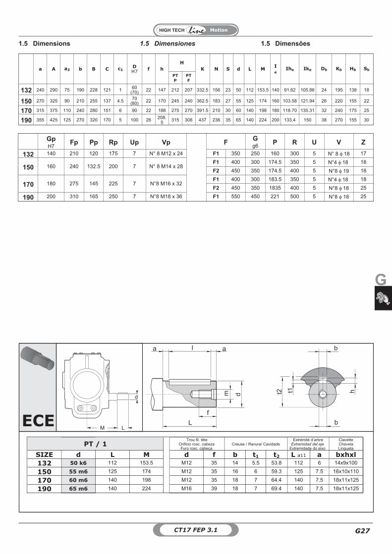
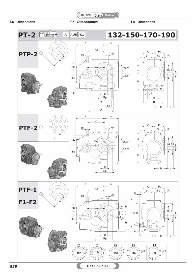
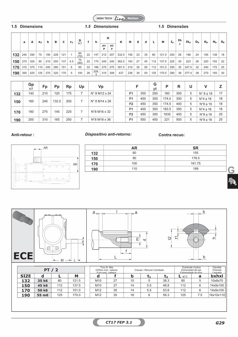
1.5 Dimensiones1.5 Dimensions 1.5 Dimensões
PTF-1
11
1
PT-1 80-100-125-140AUDA C1
F1-F2PTF-1
GF
Z
Kb
Hb
K N
22.5°
22.5°
Rp
D
Db Vp
h
H
C
M LL
Fp
Sbc1
Pp
Up
Gp
Kb
Hb
K N
Rp
D
Db Vp
h
H
C
Fp
Sbc1
Pp
Up
Gp
22.5°
22.5°
Ie
Ie
M LL
d
dR
V
P
(F2)U
(F1)U
OM af a2f bf tf80 175 125 64 M10
100 230 159 73 M12
125 300 210 88 M14
140 390 270 130 M18
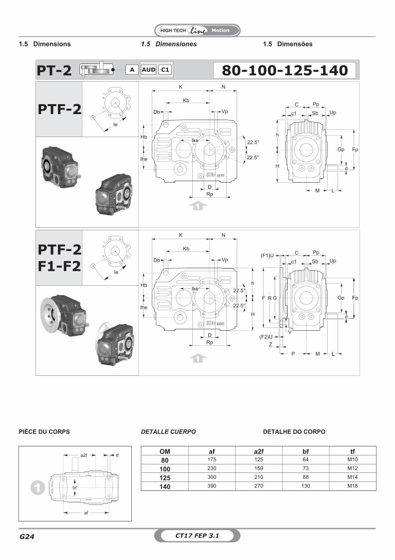
PIÈCE DU CORPS - 1 DETALHE DO CORPO - 1DETALLE CUERPO - 1
1 bf
af
a2f tf
G
Motion
G23CT17 FEP 3.1
C c1DH7
h H K N d L M Ie Db Kb Hb Sb
80 65 6,532
(30)(35)
93 100 179 85,5 24 j6 50 65 80 13 135 77 10
100 77,5 7,045
(40)(50)
113 120 221 105,5 28 j6 60 77,5 100 13 170 95 13
125 90 9,055
(50)(60)
140 145 276 140,5 38 k6 80 90 127 16 215 118 15
140 110 6,5 70(60) 182 190 349 175,5 48 k6 80 110 160 26 275 150 18
AR SR80 50 72
100 55 93,5
125 60 110
140 80 124,5
AR
SR
M LL
d
ECEf
l
L
a a
m hb
t2d
t1
b
PT / 1Trou fil. tête
Orificio rosc. cabezaFuro rosc. cabeça
Creuse / Ranura/ CavidadeExtrémité d’arbre
Extremidad del ejeExtremidade do eixo
ClavetteChavetaLingueta
SIZE d L M d f b t1 t2 L a11 a bxhxl
80 24 j6 50 65 M8 20 8 4 27.3 50 5 8X7X40
100 28 j6 60 77.5 M8 20 8 4 31.3 60 5 8X7X50
125 38 k6 80 90 M10 27 10 5 41.3 80 5 10X8X70
140 48 k6 80 110 M10 27 10 5.5 51.8 80 5 14X9X70
Dispositivo anti-retorno: Contra recuo:Anti-retour :
OM Gp Fp Pp Rp Up Vp FGF8
P R U V Z
80 90 - g6 125 58,5 105 3 M8 F1 200 130 100 165 4,5 N°4 ø11 11
100 110 - g6 150 70,5 125 3 M8 F1 250 180 125 215 5 N°4 ø13 14
125 135 - g6 180 81,0 150 3 M10F1 300 230 150 265 5 N°4 ø15 16
F2 350 250(g6) 150 300 5 N°4 ø18 18
140 170 - g6 230 103,5 200 4 M12 F1 350 250 180 300 6 N°4 ø17 25
1.5 Dimensiones1.5 Dimensions 1.5 Dimensões
Motion
CT17 FEP 3.1G24
AUDA C1 80-100-125-140PT-2
PTF-2F1-F2
PTF-2
11
1
Ie
Ie
Kb
Hb
K N
22.5°
22.5°
Rp
D
Db Vp
h
H
C
M LL
Sbc1
Pp
Up
Gp
Kb
Hb
K N
Rp
D
Db Vp
h
H
C
Sbc1
Pp
Up
22.5°
22.5°
Ike
Ihe
FpGp
Ike
Ihe
LLM
d
Fp
d
Fp
d
GF
Z
R
V
P
(F2)U
(F1)U
OM af a2f bf tf80 175 125 64 M10
100 230 159 73 M12
125 300 210 88 M14
140 390 270 130 M181 bf
af
a2f tf
1.5 Dimensiones1.5 Dimensions 1.5 Dimensões
PIÈCE DU CORPS DETALHE DO CORPODETALLE CUERPO
G
Motion
G25CT17 FEP 3.1
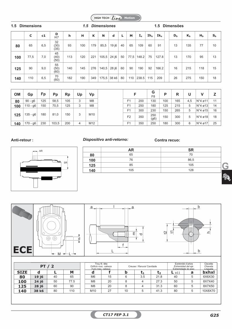
C c1DH7
h H K N d L M Ie Ihe Ike Db Kb Hb Sb
80 65 6,532
(30)(35)
93 100 179 85,5 19 j6 40 65 109 60 91 13 135 77 10
100 77,5 7,045
(40)(50)
113 120 221 105,5 24 j6 50 77,5 148.2 75 127.8 13 170 95 13
125 90 9,055
(50)(60)
140 145 276 140,5 28 j6 60 90 190 92 166.2 16 215 118 15
140 110 6,5 70(60) 182 190 349 175,5 38 k6 80 110 238.5 115 209 26 275 150 18
AR SR80 65 70
100 76 86,5
125 85 105
140 105 128
SR
AR
M LL
d
ECEf
l
L
a a
m hb
t2d
t1
b
PT / 2Trou fil. tête
Orificio rosc. cabezaFuro rosc. cabeça
Creuse / Ranura/ CavidadeExtrémité d’arbre
Extremidad del ejeExtremidade do eixo
ClavetteChavetaLingueta
SIZE d L M d f b t1 t2 L a11 a bxhxl80 19 j6 40 65 M6 15 6 3.5 21.8 40 5 6X6X30
100 24 j6 50 77.5 M8 20 8 4 27.3 50 5 8X7X40
125 28 j6 60 90 M8 20 8 4 31.3 60 5 8X7X50
140 38 k6 80 110 M10 27 10 5 41.3 80 5 10X8X70
OM Gp Fp Pp Rp Up Vp FGF8
P R U V Z
80 90 - g6 125 58,5 105 3 M8 F1 200 130 100 165 4,5 N°4 ø11 11
100 110 - g6 150 70,5 125 3 M8 F1 250 180 125 215 5 N°4 ø13 14
125 135 - g6 180 81,0 150 3 M10F1 300 230 150 265 5 N°4 ø15 16
F2 350 250(g6) 150 300 5 N°4 ø18 18
140 170 - g6 230 103,5 200 4 M12 F1 350 250 180 300 6 N°4 ø17 25
1.5 Dimensiones1.5 Dimensions 1.5 Dimensões
Dispositivo anti-retorno: Contra recuo:Anti-retour :
Motion
CT17 FEP 3.1G26
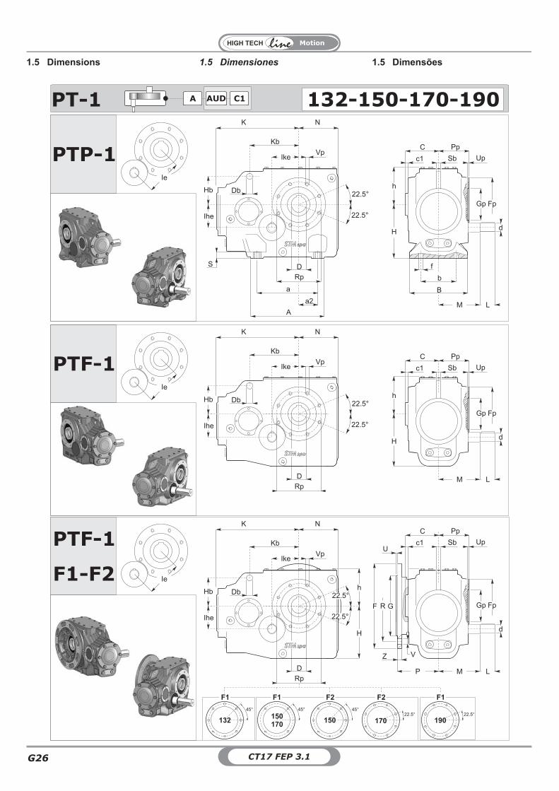
PTP-1
PTF-1
PTF-1
PTF-1
F1-F2
22.5°
K N
D
Kb
Rp
Db
22.5°
Vp
Gp Fp
Upc1
C Pp
h
H
Sb
M L
Ike
Hb
Ihe
d
Ie
K N
D
Kb
Rp
Db
Vp
Gp Fp
Upc1
C Pp
h
H
Sb
M L
Ike
Hb
Ihe
d
Ie
22.5°
22.5°
R
P
a
a2
A
S
22.5°
D
Rp
Db
22.5°
f
b
B
Gp
Upc1
C Pp
h
H
Sb
Ihe
Fp
M L
Hb
K N
Kb
VpIke
Ie
d
U
GF
Z V
PT-1 132-150-170-190AUDA C1
132
45°
F1
45°
150
170
F1
22.5°
F1
190
22.5°
F2
170150
F2
45°
1.5 Dimensiones1.5 Dimensions 1.5 Dimensões
G
Motion
G27CT17 FEP 3.1
GpH7
Fp Pp Rp Up Vp FGg6
P R U V Z
132 140 210 120 175 7 N° 8 M12 x 24 F1 350 250 160 300 5 N° 8 � 18 17
150 160 240 132.5 200 7 N° 8 M14 x 28F1 400 300 174.5 350 5 N°4 � 18 18
F2 450 350 174.5 400 5 N°8 � 19 18
170 180 275 145 225 7 N°8 M16 x 32F1 400 300 183.5 350 5 N°4 � 18 18
F2 450 350 1835 400 5 N°8 � 18 25
190 200 310 165 250 7 N°8 M18 x 36 F1 550 450 221 500 5 N°8 � 18 25
a A a2 b B C c1DH7
f h
H
K N S d L MI
eIhe Ike Db Kb Hb Sb
PT
P
PT
F
132 240 290 75 190 228 121 1 60(70) 22 147 212 207 332.5 156 23 50 112 153.5 140 91.62 105.86 24 195 138 18
150 270 325 90 210 255 137 4.5 70(80) 22 170 245 240 362.5 183 27 55 125 174 160 103.58 121.94 26 220 155 22
170 315 375 110 240 280 151 6 90 22 188 275 270 391.5 210 30 60 140 198 180 118.70 135.31 32 240 175 25
190 355 425 125 270 320 170 5 100 26 208.5 315 308 437 236 35 65 140 224 200 133,4 150 38 270 155 30
ECEf
l
L
a a
m hb
t2d
t1
bM L
d
PT / 1Trou fil. tête
Orificio rosc. cabezaFuro rosc. cabeça
Creuse / Ranura/ CavidadeExtrémité d’arbre
Extremidad del ejeExtremidade do eixo
ClavetteChavetaLingueta
SIZE d L M d f b t1 t2 L a11 a bxhxl
132 50 k6 112 153.5 M12 35 14 5.5 53.8 112 6 14x9x100
150 55 m6 125 174 M12 35 16 6 59.3 125 7.5 16x10x110
170 60 m6 140 198 M12 35 18 7 64.4 140 7.5 18x11x125
190 65 m6 140 224 M16 39 18 7 69.4 140 7.5 18x11x125
1.5 Dimensiones1.5 Dimensions 1.5 Dimensões
Motion
CT17 FEP 3.1G28
PTP-2
PTF-2
PTF-1
F1-F2
U
G
Z V
22.5°
K N
D
Rp
22.5°
VpUpc1
C Pp
h
H
Sb
Hb
Ie
Hb
Db
Ihe
Ike
Kb
M
Gp Fp
MM L
d
K N
D
Rp
Vp
Upc1
C Pp
Sb
Hb
Ie
Hb
Db
Ihe
Ike
Kb
Gp Fp
MM L
d
h
H
22.5°
22.5°
V
RF
P
a
a2
A
S
22.5°
D
Rp
Db
22.5°
f
b
B
Upc1
C Pp
h
H
Sb
Ihe
M L
Hb
K N
Kb
Vp
Ike
Ie
Gp Fp
d
AUDA C1PT-2 132-150-170-190
132
45°
F1
45°
150
170
F1
22.5°
F1
190
22.5°
F2
170150
F2
45°
1.5 Dimensiones1.5 Dimensions 1.5 Dimensões
G
Motion
G29CT17 FEP 3.1
GpH7
Fp Pp Rp Up Vp FGg6
P R U V Z
132 140 210 120 175 7 N° 8 M12 x 24 F1 350 250 160 300 5 N° 8 � 18 17
150 160 240 132.5 200 7 N° 8 M14 x 28F1 400 300 174.5 350 5 N°4 � 18 18
F2 450 350 174.5 400 5 N°8 � 19 18
170 180 275 145 225 7 N°8 M16 x 32F1 400 300 183.5 350 5 N°4 � 18 18
F2 450 350 1835 400 5 N°8 � 18 25
190 200 310 165 250 7 N°8 M18 x 36 F1 550 450 221 500 5 N°8 � 18 25
a A a2 b B C c1DH7
f h
H
K N S d L M IeIh
eIke Db Kb Hb Sb
PT
P
PT
F
132 240 290 75 190 228 121 1 60(70) 22 147 212 207 332.5 156 23 35 80 121.5 200 28 198 24 195 138 18
150 270 325 90 210 255 137 4.5 70(80) 22 170 245 240 362.5 183 27 45 112 137.5 225 30 223 26 220 155 22
170 315 375 110 240 280 151 6 90 22 188 275 270 391.5 210 30 50 112 151.0 250 35 247.5 32 240 175 25
190 355 425 125 270 320 170 5 100 26 208.5 315 308 437 236 35 55 125 170.0 280 38 277.4 38 270 155 30
SR
AR AR SR132 80 155
150 90 178.5
170 100 181.75
190 110 199
ECEf
l
L
a a
m hb
t2d
t1
bM L
d
PT / 2Trou fil. tête
Orificio rosc. cabezaFuro rosc. cabeça
Creuse / Ranura/ CavidadeExtrémité d’arbre
Extremidad del ejeExtremidade do eixo
ClavetteChavetaLingueta
SIZE d L M d f b t1 t2 L a11 a bxhxl132 35 k6 80 121.5 M10 27 10 5 38.3 80 5 10x8x70
150 45 k6 112 137.5 M10 27 14 5.5 48.8 112 6 14x9x100
170 50 k6 112 151.0 M12 35 14 5.5 53.8 112 6 14x9x100
190 55 m6 125 170.0 M12 35 16 6 59.3 125 7.5 16x10x110
1.5 Dimensiones1.5 Dimensions 1.5 Dimensões
Dispositivo anti-retorno: Contra recuo:Anti-retour :

Motion
CT17 FEP 3.1G30
1.5.1 - Estremità d'albero entrata 1.5.1 - Ende der Antriebswelle1.5.1 - Input shaft end
PT/1 PT/2d L M d L M
80 24 j6 50 65 40 65
100 28 j6 60 77,5 50 77,5
125 38 k6 80 90 60 90
132 50 k6 112 153.5 80 121.5
140 48 k6 80 110 80 110
150 55 m6 125 174 112 137.5
170 60 m6 140 198 112 151.0
190 65 m6 140 224 125 170.0
PT / 2Foro fil. testaTapped hole
Gewindebohrung KopfCreuse / Ranura/ Cavidade
Estremità d'alberoShaft end
Wellenende
LinguettaKey
Federkeil
Size d L M d f b t1 t2 L a11 abxhx
l19 j6 80 19 j6 40 65 M6 15 6 3.5 21.8 40 5 6X6X30
24 j6 100 24 j6 50 77.5 M8 20 8 4 27.3 50 5 8X7X40
28 j6 125 28 j6 60 90 M8 20 8 4 31.3 60 5 8X7X50
35 k6 132 35 k6 80 121.5 M10 27 10 5 38.3 80 5 10x8x70
38 k6 140 38 k6 80 110 M10 27 10 5 41.3 70 5 10X8X60
45 k6 150 45 k6 112 137.5 M10 27 14 5.5 48.8 112 6 14x9x100
48 k6 M10 27 10 5.5 51.8 80 5 14X9X70
50 k6 170 50 k6 112 151.0 M12 35 14 5.5 53.8 112 6 14x9x100
55 m6 190 55 m6 125 170.0 M12 35 16 6 59.3 125 7.5 16x10x110
60 m6 M12 35 18 7 64.4 140 7.5 18x11x125
65 m6 M16 39 18 7 69.4 140 7.5 18x11x125
PT / 1Foro fil. testaTapped hole
Gewindebohrung KopfCava / Keyway / Nut
Estremità d'alberoShaft end
Wellenende
LinguettaKey
Federkeil
Size d L M d f b t1 t2 L a11 abxhx
l19 j6 19 j6 M6 15 6 3.5 21.8 40 5 6X6X30
24 j6 80 24 j6 50 65 M8 20 8 4 27.3 50 5 8X7X40
28 j6 100 28 j6 60 77.5 M8 20 8 4 31.3 60 5 8X7X50
35 k6 35 k6 M10 27 10 5 38.3 80 5 10x8x70
38 k6 125 38 k6 80 90 M10 27 10 5 41.3 70 5 10X8X60
45 k6 45 k6 M10 27 14 5.5 48.8 112 6 14x9x100
48 k6 140 48 k6 80 110 M10 27 10 5.5 51.8 80 5 14X9X70
50 k6 132 50 k6 112 153.5 M12 35 14 5.5 53.8 112 6 14x9x100
55 m6 150 55 m6 125 174 M12 35 16 6 59.3 125 7.5 16x10x110
60 m6 170 60 m6 140 198 M12 35 18 7 64.4 140 7.5 18x11x125
65 m6 190 65 m6 140 224 M16 39 18 7 69.4 140 7.5 18x11x125
G
Motion
G31CT17 FEP 3.1
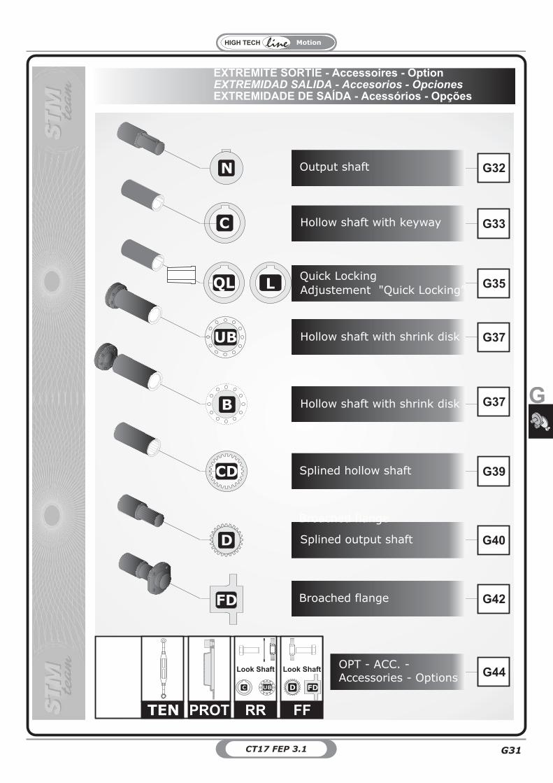
G32
DC G33
UB G37
DB G37
G40
DFD G42
G39CD
DN
G35QL
DD
G44
PROT RR FF
Look Shaft
DC UB DFDDD
Look Shaft
TEN
Hollow shaft with keyway
H kollow shaft with shrink dis
Splined output shaft
Splined hollow shaft
O tutput shaf
Broached flange
Quick Locking
A ”djustement "Quick Locking
Broached flange
OPT - ACC. -
Accessories - Options
L
H kollow shaft with shrink dis
EXTRÉMITÉ SORTIE - Accessoires - OptionEXTREMIDAD SALIDA - Accesorios - OpcionesEXTREMIDADE DE SAÍDA - Acessórios - Opções
Motion
CT17 FEP 3.1G32
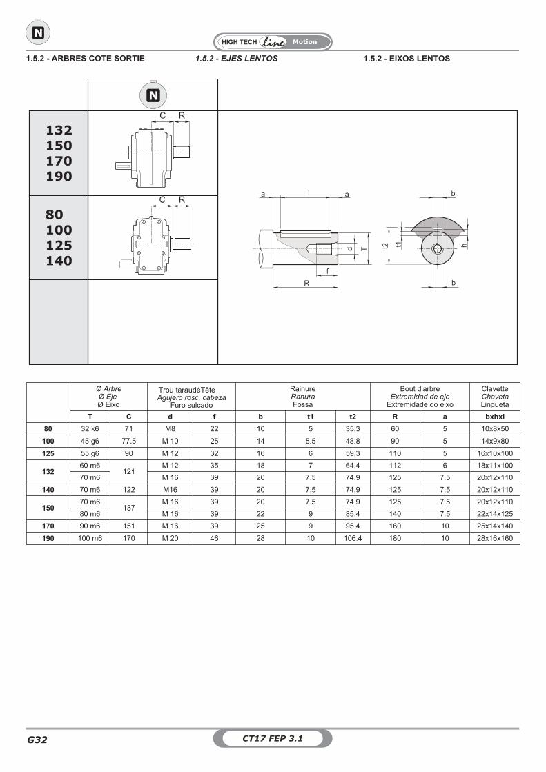
Ø ArbreØ EjeØ Eixo
Trou taraudéTêteAgujero rosc. cabeza
Furo sulcado
RainureRanuraFossa
Bout d'arbreExtremidad de eje
Extremidade do eixo
ClavetteChavetaLingueta
T C d f b t1 t2 R a bxhxl
80 32 k6 71 M8 22 10 5 35.3 60 5 10x8x50
100 45 g6 77.5 M 10 25 14 5.5 48.8 90 5 14x9x80
125 55 g6 90 M 12 32 16 6 59.3 110 5 16x10x100
13260 m6
121M 12 35 18 7 64.4 112 6 18x11x100
70 m6 M 16 39 20 7.5 74.9 125 7.5 20x12x110
140 70 m6 122 M16 39 20 7.5 74.9 125 7.5 20x12x110
15070 m6
137M 16 39 20 7.5 74.9 125 7.5 20x12x110
80 m6 M 16 39 22 9 85.4 140 7.5 22x14x125
170 90 m6 151 M 16 39 25 9 95.4 160 10 25x14x140
190 100 m6 170 M 20 46 28 10 106.4 180 10 28x16x160
f
l
R
a a
d h
b
t2T
t1
b
C R
DN
C R
80100125140
132150170190
DN
1.5.2 - ARBRES COTE SORTIE 1.5.2 - EIXOS LENTOS1.5.2 - EJES LENTOS
G
Motion
G33CT17 FEP 3.1
DC
C
80100125140
DC
Ls
DIN 472
m1
C C1
m1
D
ms ms
Sr
D
Fe
-0.1-0.2
-0.1
-0.2
Arbre machine / Eje máquina / Eixo máquina
80 100 125 140C 65 77,5 90 110
DH7
32(30)(35)
45(40)(50)
55(50)(60)
70(60)
m1 35 42.5 55 60
ms 15 15 17.5 17.5
Ls 100 125 145 185
d1h6 m3 m3s Lm m H L
min P R Ra Rb Sr Fe
8032
(30)(35)
30 30 25 M10 119 7031.8
(29.8)(34.8)
42(40)(45)
- -
10045
(50)(40)
45 1525
(32)(25)
M 10(M 12)(M 10)
125 8044.8
(49.8)(39.8)
55(60)(50)
10 M14
12555
(60)(50)
60 20 32 M 12 142 11054.8
(59.8)(49.8)
65(70)(60)
15 M14
140 70(60) 40 40 40
(35)M20
(M12) 198 150 69.8(59.8)
80(70) - -
Kit fourni sur demandeKit suministrado a pedidoKit fornecido sob encomenda
RR
1.5.2 - ARBRES COTE SORTIE 1.5.2 - EIXOS LENTOS1.5.2 - EJES LENTOS
Motion
CT17 FEP 3.1G34
Arbre machine / Eje máquina / Eixo máquina
132 150 170 190A 269 302 332 379
A1 242 274 302 340C 121 137 151 170
D 60(70)
70(80) 90 100
Dp 183 226 226 260E 56 63 70 80Lu 207.5 239.5 261 299Sr 15 15 18 18Fe M27 M27 M30 M30
VTE M20x60 M20x60 M24x75 M24x75
B C D E F G L Lu VTE
132 26.5 4 60(70) 61 120 25 180 207.5 M20
150 33.5 4.5 70(80) 68 138 36 200 239.5 M20
170 36 5 90 77 148 37 220 261 M24
190 44 5.5 100 85 170 43 250 299 M24
Lu
EF
L G
Dh
6
Dh
6
Da
11
B
C 15°
VTE
DC
132150170190
C
DC
-0.
1-
0.2
- 0.1- 0.2
DH
7
DH
7
Dp
LuDIN 472
A
A1
B
EE
Linguetta / KeyUNI 6604
Sr
Fe
D
VTE
B
Kit fourni sur demandeKit suministrado a pedidoKit fornecido sob encomenda
RR
1.5.2 - ARBRES COTE SORTIE 1.5.2 - EIXOS LENTOS1.5.2 - EJES LENTOS
G
Motion
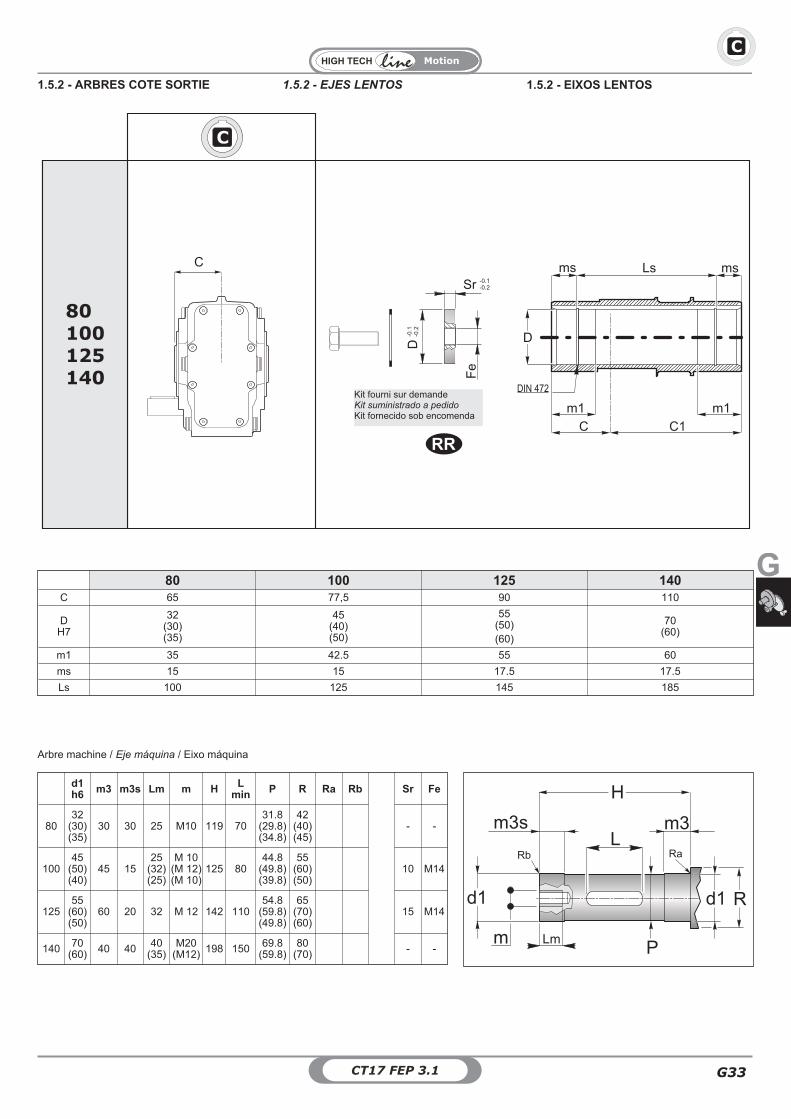
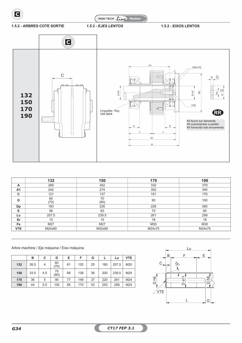
G35CT17 FEP 3.1
QL
80100125140
132150170190
QL
Lt1 m1
Lu1
dDt DubPt E
E1m3
m4
n2
s1
Lub
s2s3
Db
t2
n1 nC
CCq
Cq
OnlyPT/1 - AUD-BUSPT/2 - A - B
80 100 125 132 140 150 170 190C 65 77,5 90 121 110 137 151 170
Cq 101 113.5 126 157 146 173 187 206d 35.2 49.2 60.2 70.2 69.2 80.2 90.2 100.2dt 47 62 72 85 85 100 110 120
Dub 70 85 100 105 115 120 135 145E 91 121 131 141 141 161 181 201
E1 3.5 3.5 3.5 4.2 4.2 4.2 4.2 5.2Lt1 145 170 195 257 235 289 317 355Lu1 166 191 216 278 256 310 338 376Lub 35 35 35 35 35 35 35 35m1 21 21 21 21 21 21 21 21m3 64.5 58.5 71.5 120.8 98.8 132.8 140.8 157.8m4 1.7 1.7 1.7 2.2 2.2 2.2 2.2 2.7n2 15 15.5 16 16 16 17 17 17s1 21 21 21 21 21 21 21 21s2 14 14 14 14 14 14 14 14s3 4.5 5 6.5 10 6 13 17 15
b688
88101214
1012141416
1214141618
1214141618
141416181820
161818202022
2020222225
DH7
202530
2530353840424548
354045485055
404550556065
404550556065
45505560657075
556065707580
7075808590
n 6 7 8 8 8 10 10 10n1 2.5 3 3.5 3.5 3.5 4 4 4b
UNI 6604t2
1.5.2 - ARBRES COTE SORTIE 1.5.2 - EIXOS LENTOS1.5.2 - EJES LENTOS
Motion
CT17 FEP 3.1G36
Arbre machine / Eje máquina / Eixo máquina
t1 b1
Lu
L G
45°C
de
R
QL
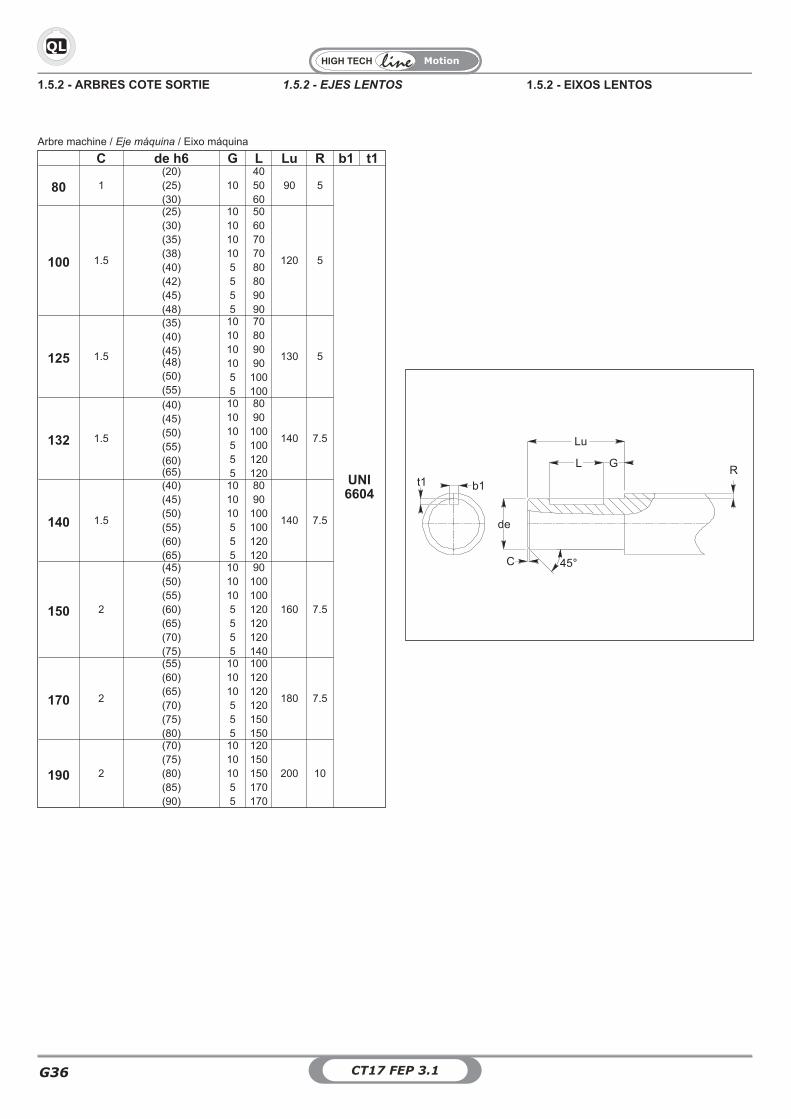
C de h6 G L Lu R b1 t1
80 1(20)(25)(30)
10405060
90 5
UNI6604
100 1.5
(25)(30)(35)(38)(40)(42)(45)(48)
101010105555
5060707080809090
120 5
125 1.5
(35)(40)(45)(48)(50)(55)
1010101055
70809090
100100
130 5
132 1.5
(40)(45)(50)(55)(60)(65)
101010555
8090
100100120120
140 7.5
140 1.5
(40)(45)(50)(55)(60)(65)
101010555
8090
100100120120
140 7.5
150 2
(45)(50)(55)(60)(65)(70)(75)
1010105555
90100100120120120140
160 7.5
170 2
(55)(60)(65)(70)(75)(80)
101010555
100120120120150150
180 7.5
190 2
(70)(75)(80)(85)(90)
10101055
120150150170170
200 10
1.5.2 - ARBRES COTE SORTIE 1.5.2 - EIXOS LENTOS1.5.2 - EJES LENTOS
G
Motion
G37CT17 FEP 3.1
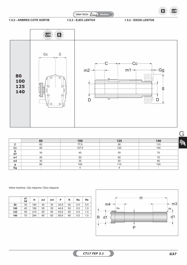
80100125140
CCc
UB
CcC
m2 Gg
g
m1
D D
DB
80 100 125 140C 65 77,5 90 110
Cc 95 107.5 125 154D
H7 35 45 55 70
m1 40 50 60 70m2 30 30 50 60g 80 100 115 155
Gg - 4 4 -
Arbre machine / Eje máquina / Eixo máquina
UBDB
d1h6 H m3 m4 P R Ra Rb
80 35 160 45 35 34.8 45 0.5 0.5
100 45 190 55 35 44.8 55 0.5 1.0
125 55 215 65 55 54.8 65 0.5 1.0
140 70 264 80 60 69.8 80 0.5 1.0
1.5.2 - ARBRES COTE SORTIE 1.5.2 - EIXOS LENTOS1.5.2 - EJES LENTOS
Motion
CT17 FEP 3.1G38
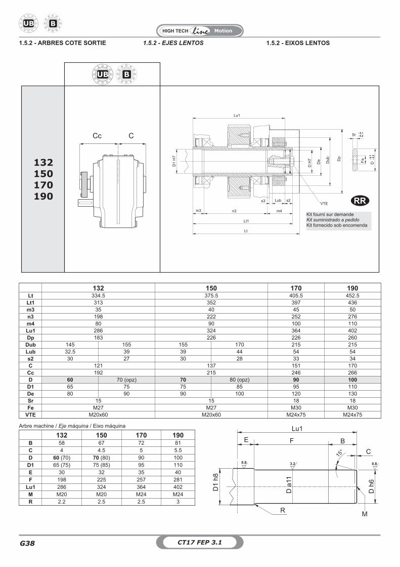
UB
132 150 170 190Lt 334.5 375.5 405.5 452.5
Lt1 313 352 397 436m3 35 40 45 50n3 198 222 252 276m4 80 90 100 110Lu1 286 324 364 402Dp 183 226 226 260
Dub 145 155 155 170 215 215Lub 32.5 39 39 44 54 54s2 30 27 30 28 33 34C 121 137 151 170
Cc 192 215 246 266D 60 70 (opz) 70 80 (opz) 90 100
D1 65 75 75 85 95 110De 80 90 90 100 120 130Sr 15 15 18 18Fe M27 M27 M30 M30
VTE M20x60 M20x60 M24x75 M24x75
Arbre machine / Eje máquina / Eixo máquina
132 150 170 190B 58 67 72 81C 4 4.5 5 5.5D 60 (70) 70 (80) 90 100
D1 65 (75) 75 (85) 95 110E 30 32 35 40F 198 225 257 281
Lu1 286 324 364 402M M20 M20 M24 M24R 2.2 2.5 2.5 3
Da11
0.8 3.2 0.8
Lu1
F B
15°
E
C
R M
D1
h8
Dh
6
CCc
132150170190
UB DB
Lu1
m3 n3
s3 s2
Lt1
Lt
m4
LubVTE
Sr
Fe
D1
H7
DH
7
De D
p
DDu
b -0.
1-
0.2
- 0.1- 0.2
Kit fourni sur demandeKit suministrado a pedidoKit fornecido sob encomenda
RR
DB
1.5.2 - ARBRES COTE SORTIE 1.5.2 - EIXOS LENTOS1.5.2 - EJES LENTOS
G
Motion
G39CT17 FEP 3.1
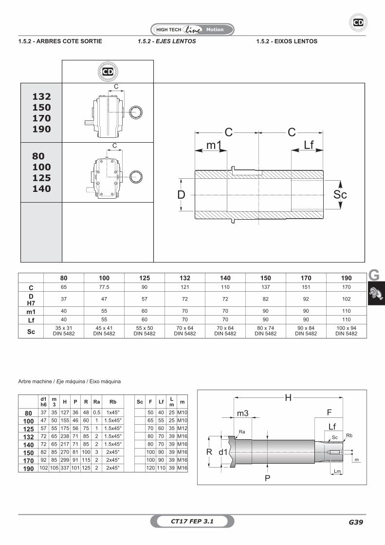
C
80100125140
132150170190
C
CD
CC
Sc
m1
D
Lf
CD
80 100 125 132 140 150 170 190
C 65 77.5 90 121 110 137 151 170
DH7
37 47 57 72 72 82 92 102
m1 40 55 60 70 70 90 90 110
Lf 40 55 60 70 70 90 90 110
Sc35 x 31
DIN 548245 x 41
DIN 548255 x 50
DIN 548270 x 64
DIN 548270 x 64
DIN 548280 x 74
DIN 548290 x 84
DIN 5482100 x 94DIN 5482
Arbre machine / Eje máquina / Eixo máquina
d1h6
m3 H P R Ra Rb Sc F Lf L
m m
80 37 35 127 36 48 0.5 1x45° 50 40 25 M10
100 47 50 155 46 60 1 1.5x45° 65 55 25 M10
125 57 55 175 56 75 1 1.5x45° 70 60 35 M12
132 72 65 238 71 85 2 1.5x45° 80 70 39 M16
140 72 65 217 71 85 2 1.5x45° 80 70 39 M16
150 82 85 270 81 100 3 2x45° 100 90 39 M16
170 92 85 299 91 115 2 2x45° 100 90 39 M16
190 102 105 337 101 125 2 2x45° 120 110 39 M16
1.5.2 - ARBRES COTE SORTIE 1.5.2 - EIXOS LENTOS1.5.2 - EJES LENTOS
Motion
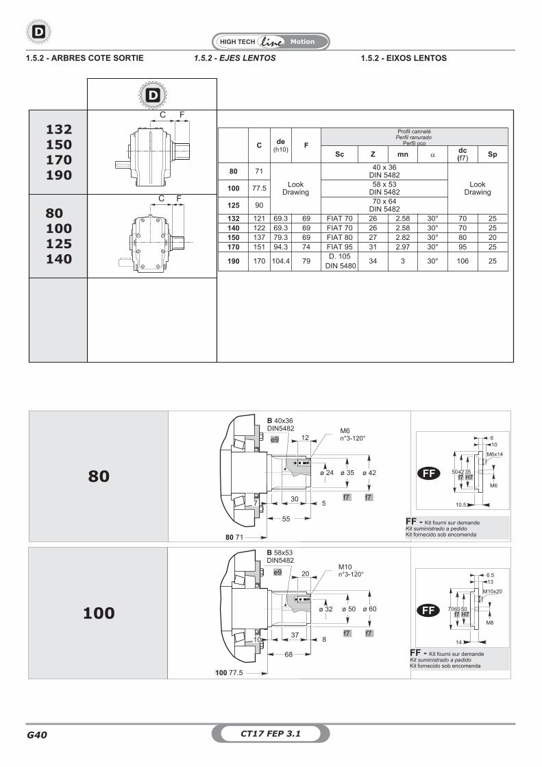
CT17 FEP 3.1G40
DD
DD
C F
C
80100125140
132150170190
F
C de(h10)
F
Profil canneléPerfil ranurado
Perfil oco
Sc Z mn �dc(f7) Sp
80 71
LookDrawing
40 x 36DIN 5482
LookDrawing100 77.5 58 x 53
DIN 5482
125 90 70 x 64DIN 5482
132 121 69.3 69 FIAT 70 26 2.58 30° 70 25140 122 69.3 69 FIAT 70 26 2.58 30° 70 25150 137 79.3 69 FIAT 80 27 2.82 30° 80 20170 151 94.3 74 FIAT 95 31 2.97 30° 95 25
190 170 104.4 79D. 105
DIN 548034 3 30° 106 25
80
100
M6x14
10.5
6
35H7
42f7
50
10
M6
M10x20
14
6.5
50H7
60f7
70
13
M8
e9 12M6n°3-120°
ø 42ø 35ø 24
305
55
f7 f77
B 40x36DIN5482
ø 60ø 50ø 32
20
B 58x53DIN5482
e9M10n°3-120°
837
68
f7 f710
7180
77.5100
FF
FF
FF - Kit fourni sur demandeKit suministrado a pedidoKit fornecido sob encomenda
FF - Kit fourni sur demandeKit suministrado a pedidoKit fornecido sob encomenda
1.5.2 - ARBRES COTE SORTIE 1.5.2 - EIXOS LENTOS1.5.2 - EJES LENTOS
G
Motion
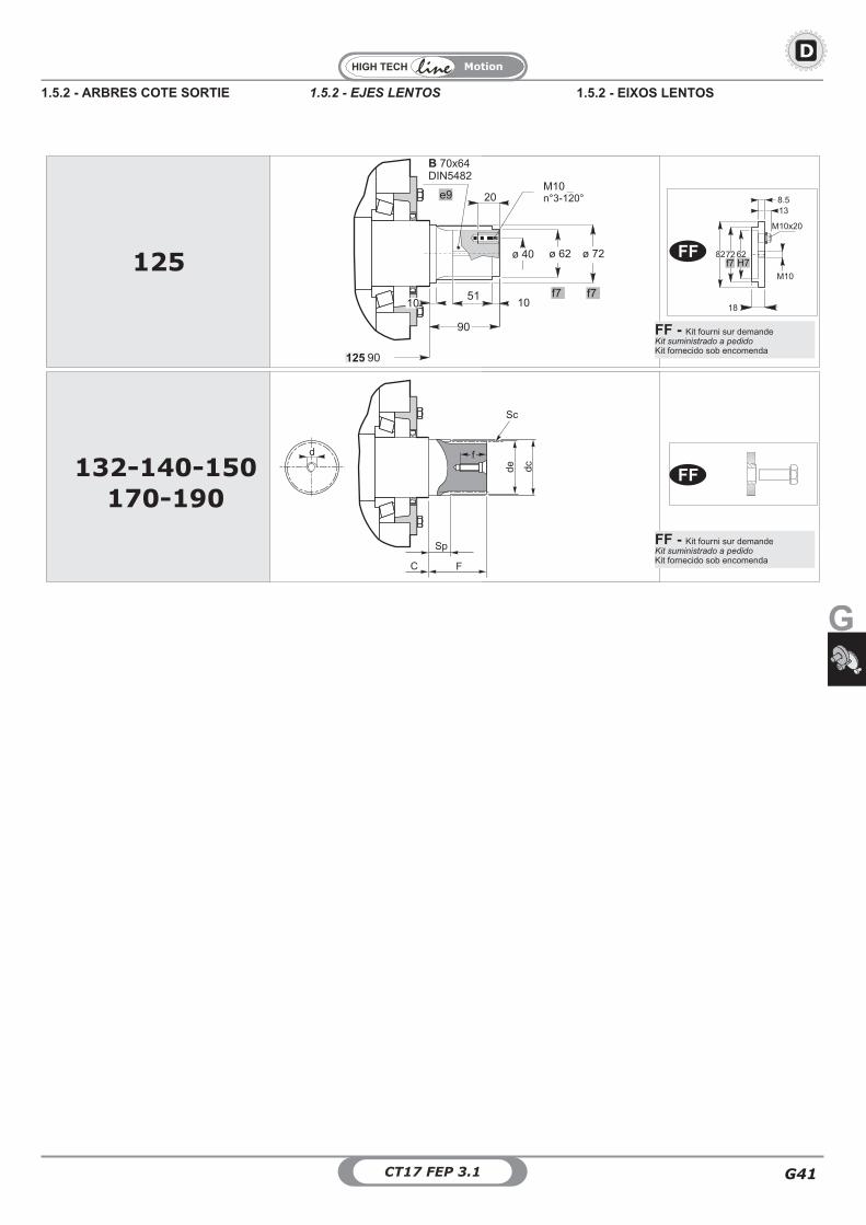
G41CT17 FEP 3.1
DD
F
Sp
Sc
de
dc
fd
125
M10x20
18
8.5
62H7
72f7
82
13
M10
ø 72ø 62ø 40
20
B 70x64DIN5482
e9M10n°3-120°
1051
90
f7 f710
132-140-150
170-190
90125
C
FF
FF
FF - Kit fourni sur demandeKit suministrado a pedidoKit fornecido sob encomenda
FF - Kit fourni sur demandeKit suministrado a pedidoKit fornecido sob encomenda
1.5.2 - ARBRES COTE SORTIE 1.5.2 - EIXOS LENTOS1.5.2 - EJES LENTOS
Motion
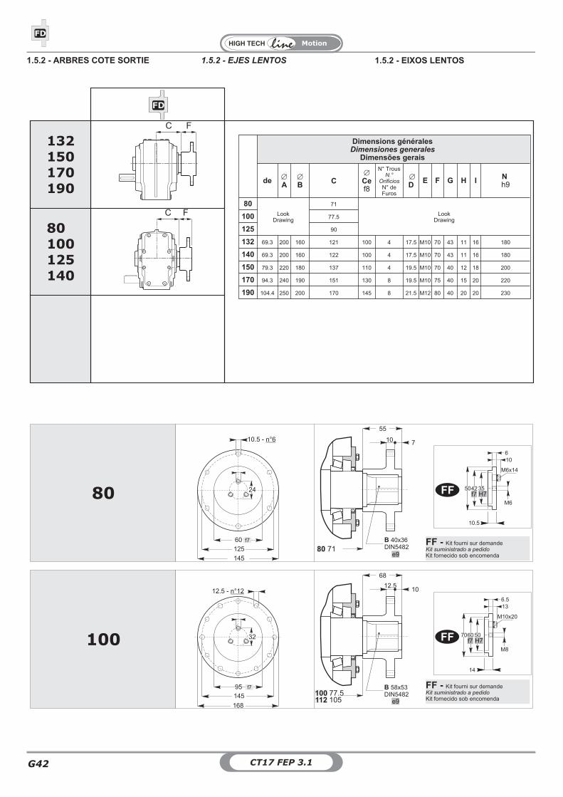
CT17 FEP 3.1G42
DFD
DFD
C F
C
80100125140
132150170190
F
Dimensions généralesDimensiones generales
Dimensões gerais
de �
A�
B C�
Cef8
N° TrousN.°
OrificiosN° deFuros
�
DE F G H I N
h9
80Look
Drawing
71
LookDrawing100 77.5
125 90
132 69.3 200 160 121 100 4 17.5 M10 70 43 11 16 180
140 69.3 200 160 122 100 4 17.5 M10 70 43 11 16 180
150 79.3 220 180 137 110 4 19.5 M10 70 40 12 18 200
170 94.3 240 190 151 130 8 19.5 M10 75 40 15 20 220
190 104.4 250 200 170 145 8 21.5 M12 80 40 20 20 230
B 58x53DIN5482
f7
10.5 - n°6
145
125
60
e9
B 40x36DIN5482
55
10 7
e9
68
12.510
f7
12.5 - n°12
168
145
95
24
M6x14
10.5
6
35H7
42f7
50
10
M6
M10x20
14
6.5
50H7
60f7
70
13
M8
32
80
100
7180
77.5105
100112
FF
FF
FF - Kit fourni sur demandeKit suministrado a pedidoKit fornecido sob encomenda
FF - Kit fourni sur demandeKit suministrado a pedidoKit fornecido sob encomenda
1.5.2 - ARBRES COTE SORTIE 1.5.2 - EIXOS LENTOS1.5.2 - EJES LENTOS
G
Motion
G43CT17 FEP 3.1
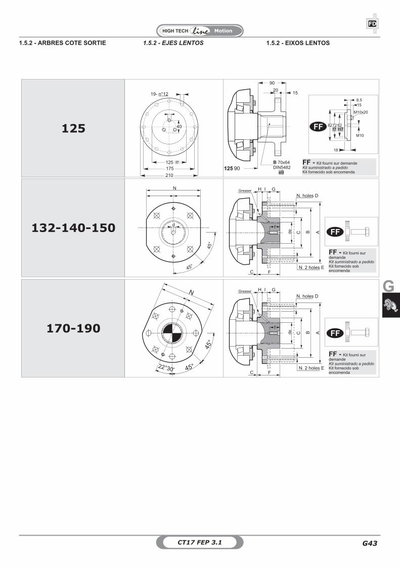
DFD
F
ABCde
GIHGreaser
N. 2 holes E
N. holes D
C
f
N
45°
45°
d
132-140-150
B 70x64DIN5482
e9
90
2015
f7
19- n°12
210
175
125
M10x20
18
8.5
62H7
72f7
82
15
M10
40125
90125
F
ABCde
GIHGreaser
N. 2 holes E
N. holes D
C
f170-190
N
45°
45°22°30'
FF
FF
FF
FF - Kit fourni sur demandeKit suministrado a pedidoKit fornecido sob encomenda
FF - Kit fourni surdemandeKit suministrado a pedidoKit fornecido sobencomenda
FF - Kit fourni surdemandeKit suministrado a pedidoKit fornecido sobencomenda
1.5.2 - ARBRES COTE SORTIE 1.5.2 - EIXOS LENTOS1.5.2 - EJES LENTOS
Motion
CT17 FEP 3.1G44
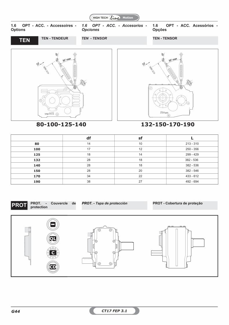
df sf L
80 14 10 213 - 310
100 17 12 250 - 356
125 18 14 299 - 429
132 28 18 382 - 536
140 28 18 382 - 536
150 28 20 382 - 546
170 34 22 433 - 612
190 38 27 492 - 694
df
SfL
30 max30 max
df
Sf
L
30 max30 max
80-100-125-140 132-150-170-190
1.6 OPT - ACC. - Accesorios -Opciones
1.6 OPT - ACC. - Accessoires -Options
1.6 OPT - ACC. Acessórios -Opções
TEN - TENSOR TEN - TENSORTEN - TENDEURTEN
PROT. - Tapa de protección PROT - Cobertura de proteçãoPROT. - Couvercle deprotectionPROT
D
QL
C
CD
Recommended