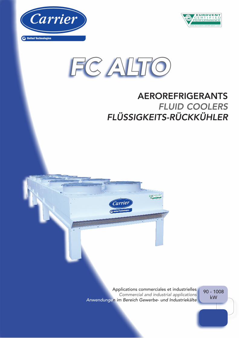
FC ALTO
90 - 1008kW
AEROREFRIGERANTSFLUID COOLERS
FLÜSSIGKEITS-RÜCKKÜHLER
Applications commerciales et industriellesCommercial and industrial applications
Anwendungen im Bereich Gewerbe- und Industriekälte

3
ANWENDUNGDie Flüssigkeits-Rückkühler der Serie FC ALTO decken einen großen Leistungsbereich für gewerbliche und industrielle Anwendungen ab.Die FC ALTO Rückkühler sind zur Außenaufstellung vorgesehen. Für alle flüssigen Wärmeträger, die mit dem Rohrmaterial Kupfer zum Einsatz kommen können und eine maximale Betriebstemperatur von 60 ° C (Bitte für Temperaturen über 60 ° C anfragen.) ermöglichen. Alle Modelle sind mit vertikalen oder horizontalen Luftstrom lieferbar (muss Angegeben werden).Sämtliche flüssigkeits-rückkühler sind mit CE-Kennzeichnung versehen.(Mit ERP. Direktive 2009/125/CE).
BEZEICHNUNG
GEHÄUSEVerzinkte Bleche – Polyester pulverbeschichtet– und weiß (RAL 7035) lackierter Stahlbleche verfügen sorgen für eine hohe Beständigkeit der Verflüssiger gegen UV-Strahlung und Korrosion.Die einzelnen Verflüssigerpakete sind auf einem tragfähigen Rahmen montiert, wodurch– bei gleichzeitiger Verstärkung der Steifigkeit des Gesamtaufbaus – Verwindungen des Paketes verhindert und die Lamellen bei Installations- und Wartungsarbeiten geschützt werden.Jeder Lüfter verfügt über ein eigenes Lüftergehäuse, um einen gleichmäßigen Luftdurchfluss über die gesamte Austauscherfläche zu gewährleisten und die Regelung zu erleichtern.Sämtliche Modelle haben Hubösen, zur Handhabung mit Traverse
WÄRMETAUSCHERBLOCKDie flüssigkeits-rückkühler FC ALTO besteht aus einem Paket von Kupferrohren und Aluminiumlamellen, was zu einer optimalen Wärmeabfuhr beiträgt.Rohre und Lamellen sind durch mechanische Ausdehnung fest und eng miteinander verbunden.Der Einsatz modernster Maschinen in allen Produktionsstufen ermöglicht uns, flüssigkeits-rückkühler zu bauen, die höchsten Qualitätsansprüchen gerecht werden..Die Effizienz und Kompaktheit der FC ALTO-flüssigkeits-rückkühler sind das Ergebnis zielgerichteter technischer Lösungen im Hinblick auf Materialien und Produktionsabläufe.
Standardabstand der Lamellen : 2,2 mm
APPLICATIONLa gamme d’aéroréfrigérants FC ALTO permet de couvrir une large gamme de puissance pour des applications commerciales et industrielles.Les aéroréfrigérants de la gamme FC ALTO sont prévus pour des installations extérieures pour toutes les applications de fluides compatibles avec le cuivre et jusqu’à une température d’utilisation de 60°C (nous consulter pour les températures > 60°C).Tous les modèles fonctionnent en soufflage vertical ou horizontal (option à préciser à la commande).Marquage CE sur tous les aéroréfrigérants.(ERP compris. Directive 2009/125/CE).
DESIGNATION
CARROSSERIEL’ensemble des aéroréfrigérants, de la gamme FC ALTO, bénéficie d’une excellente résistance à la corrosion et d’une excellente tenue lors d’expositions aux UV, obtenues par l’utilisation de tôles galvanisées peintes en blanc (RAL7035) par application d’une poudre polyester cuite au four.Chaque batterie est fixée sur un châssis de forte épaisseur qui, tout en augmentant la rigidité de l’ensemble, limite les flexions et protège les batteries lors des opérations d’installation et de maintenance.Chaque ventilateur possède son propre caisson de ventilation de manière à assurer une répartition homogène du flux d’air sur l’ensemble de l’échangeur et à faciliter la régulation.Œillets de levage, pour manutention avec palonnier, sur tous les modèles.
BATTERIELa gamme FC ALTO est basée sur l’association de tubes en cuivre et d’ailettes aluminium, aux profils spécialement développés pour un rendement thermique optimum.Tubes et ailettes sont intimement et définitivement assemblés par l’expansion mécanique des tubes.L’emploi de machines de dernière génération à chaque étape de fabrication, nous permet de produire des échangeurs de très haute qualité.L’efficacité et la compacité des aéroréfrigérants FC ALTO résultent des solutions techniques choisies pour les matériaux et les procédés d’assemblage.
Ecartement standard des ailettes : 2,2 mm
APPLICATIONThe FC ALTO fluid coolers cover a large range of capacity for commercial and industrial applications.The FC ALTO fluid coolers are designed for external installations, for all applications using fluids compatible with copper and maximum working temperature of 60°C (please consult us for temperature > 60°C).All models are available with vertical or horizontal airflow (to be specified in the order).All units are CE marked.(Including ERP. Directive 2009/125/CE).
MODEL DESIGNATION
CASINGBuilt in galvanised steel sheet and white painted (RAL7035) by the application of a polyester powder, oven baked, FC ALTO fluid coolers casings are prepared to resist to UV exposition and corrosive conditions.Each coil is mounted on a strong frame, increasing assembling rigidity, reducing bending and guaranteeing fins protection during installation and maintenance operation.The casing is designed with individual compartment for fans. Airflow is thus homogeneously distributed on the coil and the fluid coolers pressure regulation is made easier.Lifting eyes on all models, to be used with a rudder bar.
COILSFC ALTO range is based on the association of copper tubes and aluminium fins especially designed to guarantee optimum thermal performance.Tubes and fins are intimately and definitively fit together per mechanical expansion of tubes.Each step of manufacturing is ensured by last generations of machines that allow to produce high quality coils.Efficiency and compactness of FC ALTO fluid coolers are the result of technical choices in terms of materials and assembling technologies.
Standard fin spacing : 2.2 mm
Aéroréfrigérant Fluid coolerFlüssigkeits-Rückkühler
FCAL
Type de moduleModel of rowModultypMS = Module simple Single row Einreihiges ModulMD = Module double Double row Zweireihiges Modul
MS91
Vitesse de rotation Rotation speedDrehzahl
6PH SH
VentilationFanLüfter
C
Type de batterieCoil typeArt des Verflüssigerpakets
4
Nb. de moteursMotor quantityAnzahlMotoren
Type de soufflageType of airflowTyp LuftführungSV = Soufflage vertical Vertical airflow Vertikale LuftführungSH = Soufflage horizontal Horizontal airflow Horizontale Luftführung
DESCRIPTIF TECHNIQUETECHNICAL FEATURES
TECHNISCHE KENNDATEN

4
D’autres matériaux sont disponibles sur demande dans le cas d’utilisation dans des atmosphères salines ou polluées :• Tubes cuivre / ailettes aluminium protection Vinyl.• Tubes cuivre / ailettes aluminium protection " Blygold ".
VENTILATION
MOTEURSLa ventilation de la gamme FC ALTO est assurée par des motoventilateurs équipés de moteurs bi-vitesse par couplage étoile ou triangle. Câblage standard en une seule vitesse.Câblage deux vitesses en option (sauf 6PH).• Plage de température : -30°C et +45°C,• Tension : - 400V(+7%/-10%)/~3/50Hz), pour les modèles PH/PL, - 230V(+7%/-10%)/~3/50Hz), pour les modèles PL couplés en triangle,• Protection IP55 (CEI 34-5), trous de purge et étanchéité d’arbre par bague nylon.• Classe F (CEI 85 et CEI 34-1).• Fréquence maximale autorisée de 20 démarrages par heure (cf. manuel d’assistance technique).Les moteurs sont intégrés dans une virole de dernière génération, réduisant le niveau sonore tout en augmentant l’efficacité aéraulique du couple moteur/hélice.Les moteurs montés en standard sont câblés individuellement dans une boite à bornes commune, située à l’extrémité de l’aéroréfrigérant, du côté des raccordements frigorifiques : une boite par ligne de ventilateurs.En cas d’arrêt prolongé de l’installation, faire tourner les moteurs des ventilateurs au moins deux heures par semaine.Pour toute application à température ambiante inférieure à -10°C, des précautions sont nécessaires pour le démarrage des moteurs, se référer à la notice de mise en service.
HELICESLes hélices retenues permettent une atténuation acoustique importante, tout en conservant des performances aérauliques élevées, grâce notamment à :• une répartition uniforme de la charge aéraulique sur les pales,• une optimisation des angles d’incidence limitant les turbulences à l’aspiration de l’hélice,• un profil d’hélice optimisé garantissant un coefficient de traînée faible,• un équilibrage dynamique de l’hélice dans deux plans.
Alternative fins and tubes materials are available upon request, in case of saline or polluted atmospheres :•Coppertubes/aluminiumfinswithVinylcoating.•Coppertubes/aluminiumfinswith“Blygold ” coating
VENTILATION
MOTORSFC ALTO fluid coolers are equipped with fansets. Those fansets are proposed with two speeds motors, " star/delta " type :Standard wiring for only one speed.Two-speed wiring on option (except 6PH).•Temperaturerange: -30°C and +45°C.•Voltage: - 3-phase supply 400V (+7%/-10%)/~3/50Hz) for PH and PL models, - 3-phase supply 230V (+7%/-10%)/~3/50Hz) for PL models,•ProtectionIP55(CEI34-5).Drain-holeand seal with nylon gaskets.•ClassF(CEI85andCEI34-1)•Recommendedmaximumfrequencyof starting : 20 starts per hour. (consult installation and operation manual)Motors are integrated in high efficiency shrouds, reducing sound power level and increasing airflow effectiveness of motor/propeller couple.Standard motors are individually connected to a common terminal box located on the header sideIn case of prolonged stoppage of the installation, run the fan motors at least 2 hours per week.For all applications with ambient temperature below -10°C, please apply recommendations for start up of motors, mentioned in the operating instructions leaflet.
PROPELLERSThe selected fans enable a significant sound reduction, while keeping high airflow performances. This is the result of :•abalanceddistributionoftheairloadon the fan blades,•anoptimisationoftheanglesofincidence avoiding fan turbulence at the suction,•anoptimisedfanprofileallowingalowdrag coefficient,•adynamicbalancingofthefanintwoplans.
Auf Wunsch sind weitere Materialien erhältlich für den Einsatz in salzhaltiger oder stark verschmutzter Luft :•Kupferrohre/Aluminiumlamellenmit Vinylbeschichtung.•Kupferrohre/Aluminiumlamellenmit “Blygold”-Beschichtung.
LUFTFÜHRUNG
MOTORENDie Luftführung erfolgt der Reihe FC ALTO durch Motorlüfter mit zwei Geschwindigkeiten (unterchiedliche Drehzahlen) dje nach Verdrahtung (Stern oder Dreieck).Standard-Verdrahtung für eine Geschwindigkeit.Verdrahtung für zwei Geschwindigkeiten auf Wunsch (außer 6PH).•Temperaturbereich:-30°Cbis+45°C•Spannung: - 400 V (+7 %/-10 %)/~3/50 Hz), für die Modelle PH / PL. - 230 V (+7 %/-10 %)/~3/50 Hz), für die Modelle PL bei Dreieck-Verdrahtung.•SchutzklasseIP55(CEI34-5),Abflussöffnung und Dichtung aus Nylon.•KlasseF(CEI85undCEI34-1).•MaximalzulässigeAnzahlder Startvorgänge: 20 pro Stunde (siehe Handbuch zur Inbetriebnahme und Technisches Handbuch genaue Titel der betreffenden Handbücher)Die Ummantelung der Motoren entspricht dem neuesten Stand der Technik, so dass der Schalldruckpegel reduziert und gleichzeitig der Wirkungsgrad der Luftführung der Motor/Lüfter-Einheit erhöht wird. Die Motoren in Standardausführung sind individuell in einem Kasten mit gemeinsamer Klemmleiste verdrahtet (ein Kasten je Lüfterreihe), der sich an der Stirnseite des Verflüssigers befindet, seitlich der kältetechnischen Anschlüsse.Sollte die Anlage über einen längeren Zeitraum ausgeschaltet sein, lassen Sie die Lüftermotoren mindestens zwei Stunden proWoche laufen. Bei allen Anwendungen mit Umgebungstemperaturen von unter -10 °C sind entsprechende Vorkehrungen für den Motorstart zu treffen, siehe hierzu auch Handbuch zur Inbetriebnahme.
LÜFTERDie von uns eingesetzten Lüfter ermöglichen eine erhebliche Senkung des Geräuschpegels, während gleichzeitig die optimalenLuftführungseigenschaften erhalten bleiben,. Dies basiert auf :•einergleichmäßigenVerteilungder Luftführung über die Lüfterblätter.•einenoptimiertenEinfallswinkel,waszu weniger Luftverwirbelungen im Ansaugbereich des Lüfters führt.•einemoptimiertenLüfterprofil,wasfür einen geringen Luftwiderstandswert sorgt.•einemdymanischenGleichgewichtdes Lüfters in zwei Ebenen.
DESCRIPTIF TECHNIQUETECHNICAL FEATURES
TECHNISCHE KENNDATEN
5
DESCRIPTIF TECHNIQUETECHNICAL FEATURES
TECHNISCHE KENNDATEN
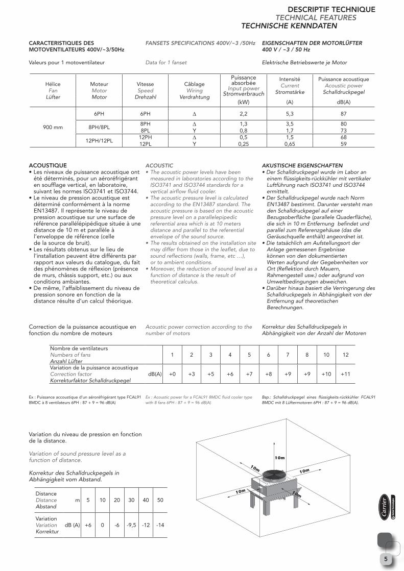
CARACTERISTIQUES DES MOTOVENTILATEURS 400V/~3/50Hz
Valeurs pour 1 motoventilateur
ACOUSTIQUE• Les niveaux de puissance acoustique ont été déterminés, pour un aéroréfrigérant en soufflage vertical, en laboratoire, suivant les normes ISO3741 et ISO3744.• Le niveau de pression acoustique est déterminé conformément à la norme EN13487. Il représente le niveau de pression acoustique sur une surface de référence parallélépipédique située à une distance de 10 m et parallèle à l’enveloppe de référence (celle de la source de bruit).• Les résultats obtenus sur le lieu de l’installation peuvent être différents par rapport aux valeurs du catalogue, du fait des phénomènes de réflexion (présence de murs, châssis support, etc.) ou aux conditions ambiantes.• De même, l’affaiblissement du niveau de pression sonore en fonction de la distance résulte d’un calcul théorique.
Correction de la puissance acoustique en fonction du nombre de moteurs
Ex : Puissance accoustique d’un aéroréfrigérant type FCAL91 8MDC à 8 ventilateurs 6PH : 87 + 9 = 96 dB(A)
Variation du niveau de pression en fonction de la distance.
Variation of sound pressure level as a function of distance.
Korrektur des Schalldruckpegels in Abhängigkeit vom Abstand.
FANSETS SPECIFICATIONS 400V/~3 /50Hz
Data for 1 fanset
ACOUSTIC•Theacousticpowerlevelshavebeen measured in laboratories according to the ISO3741 and ISO3744 standards for a vertical airflow fluid cooler.•Theacousticpressureleveliscalculated accordingtotheEN13487standard.The acoustic pressure is based on the acoustic pressure level on a parallelepipedic referential area which is at 10 meters distance and parallel to the referential envelope of the sound source.•Theresultsobtainedontheinstallationsite may differ from those in the leaflet, due to sound reflections (walls, frame, etc …), or to ambient conditions.•Moreover,thereductionofsoundlevelasa function of distance is the result of theoretical calculus.
Acoustic power correction according to the number of motors
Ex:AcousticpowerforaFCAL918MDCfluidcoolertypewith8fans6PH:87+9=96dB(A)
EIGENSCHAFTEN DER MOTORLÜFTER400 V / ~3 / 50 Hz
Elektrische Betriebswerte je Motor
AKUSTISCHE EIGENSCHAFTEN•DerSchalldruckpegelwurdeimLaboran einem flüssigkeits-rückkühler mit vertikaler Luftführung nach ISO3741 und ISO3744 ermittelt.•DerSchalldruckpegelwurdenachNorm EN13487bestimmt.Darunterverstehtman den Schalldruckpegel auf einer Bezugsoberfläche (parallele Quaderfläche), die sich in 10 m Entfernung befindet und parallel zum Referenzgehäuse (das die Geräuschquelle enthält) angeordnet ist.•DietatsächlichamAufstellungsortder Anlage gemessenen Ergebnisse können von den dokumentierten Werten aufgrund der Gegebenheiten vor Ort (Reflektion durch Mauern, Rahmengestell usw.) oder aufgrund von Umweltbedingungen abweichen.•DarüberhinausbasiertdieVerringerungdes Schalldruckpegels in Abhängigkeit von der Entfernung auf theoretischen Berechnungen.
Korrektur des Schalldruckpegels in Abhängigkeit von der Anzahl der Motoren
Bsp.: Schalldruckpegel eines flüssigkeits-rückkühler FCAL91 8MDCmit8Lüftermotoren6PH:87+9=96dB(A).
HéliceFan
Lüfter
MoteurMotorMotor
VitesseSpeed
Drehzahl
CâblageWiring
Verdrahtung
Puissanceabsorbée
Input powerStromverbrauch
IntensitéCurrent
Stromstärke
Puissance acoustiqueAcoustic power
Schalldruckpegel
(kW) (A) dB(A)
900 mm
6PH 6PH ∆ 2,2 5,3 87
8PH/8PL8PH ∆ 1,3 3,5 808PL Y 0,8 1,7 73
12PH/12PL12PH ∆ 0,5 1,5 6812PL Y 0,25 0,65 59
Nombre de ventilateursNumbers of fansAnzahl Lüfter
1 2 3 4 5 6 7 8 10 12
Variation de la puissance acoustiqueCorrection factorKorrekturfaktor Schalldruckpegel
dB(A) +0 +3 +5 +6 +7 +8 +9 +9 +10 +11
DistanceDistanceAbstand
m 5 10 20 30 40 50
VariationVariationKorrektur
dB (A) +6 0 -6 -9,5 -12 -14
10m
10m10m
10m
10m
6
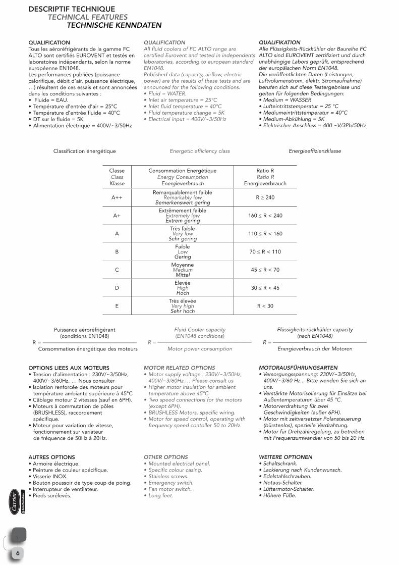
QUALIFICATIONTous les aéroréfrigérants de la gamme FC ALTO sont certifiés EUROVENT et testés en laboratoires indépendants, selon la norme européenne EN1048.Les performances publiées (puissance calorifique, débit d’air, puissance électrique, …) résultent de ces essais et sont annoncées dans les conditions suivantes :• Fluide = EAU.• Température d’entrée d’air = 25°C• Température d’entrée fluide = 40°C• DT sur le fluide = 5K• Alimentation électrique = 400V/~3/50Hz
Classification énergétique
Puissance aéroréfrigérant(conditions EN1048)
R = ___________________________________
Consommation énergétique des moteurs
OPTIONS LIEES AUX MOTEURS• Tension d’alimentation : 230V/~3/50Hz, 400V/~3/60Hz, … Nous consulter• Isolation renforcée des moteurs pour température ambiante supérieure à 45°C• Câblage moteur 2 vitesses (sauf en 6PH).• Moteurs à commutation de pôles (BRUSHLESS), raccordement spécifique.• Moteur pour variation de vitesse, fonctionnement sur variateur de fréquence de 50Hz à 20Hz.
AUTRES OPTIONS • Armoire électrique. • Peinture de couleur spécifique.• Visserie INOX.• Bouton poussoir de type coup de poing.• Interrupteur de ventilateur.• Pieds surélevés.
QUALIFICATIONAll fluid coolers of FC ALTO range are certified Eurovent and tested in independents laboratories, according to european standard EN1048.Published data (capacity, airflow, electric power) are the results of these tests and are announced for the following conditions.•Fluid=WATER.• Inletairtemperature=25°C• Inletfluidtemperature=40°C•Fluidtemperaturechange=5K•Electricalinput=400V/~3/50Hz
Energetic efficiency class
Fluid Cooler capacity (EN1048conditions)
R=___________________________________
Motor power consumption
MOTOR RELATED OPTIONS•Motorsupplyvoltage:230V/~3/50Hz, 400V/~3/60Hz … Please consult us•Highermotorinsulationforambient temperature above 45°C•Twospeedconnectionsforthemotors (except 6PH).•BRUSHLESSMotors,specificwiring.•Motorforspeedcontrol,operatingwith frequency speed contoller 50 to 20Hz.
OTHER OPTIONS•Mountedelectricalpanel.•Specificcolourcasing.•Stainlessscrews.•Emergencyswitch.•Fanmotorswitch.•Longfeet.
QUALIFIKATIONAlle Flüssigkeits-Rückkühler der Baureihe FC ALTO sind EUROVENT zertifiziert und durch unabhängige Labors geprüft, entsprechend dereuropäischenNormEN1048.Die veröffentlichten Daten (Leistungen, Luftvolumenstrom, elektr. Stromaufnahme) berufen sich auf diese Testergebnisse und gelten für folgenden Bedingungen:•Medium=WASSER•Lufteintrittstemperatur=25°C•Mediumeintrittstemperatur=40°C•Medium-Abkühlung=5K•ElektrischerAnschluss=400~V/3Ph/50Hz
Energieeffizienzklasse
Flüssigkeits-rückkühler capacity (nachEN1048)
R=___________________________________
Energieverbrauch der Motoren
MOTORAUSFÜHRUNGSARTEN•Versorgungsspannung:230V/~3/50Hz, 400V/~3/60 Hz... Bitte wenden Sie sich an uns.•VerstärkteMotorisolierungfürEinsätzebei Außentemperaturen über 45 °C.•Motorverdrahtungfürzwei Geschwindigkeiten (außer 6PH).•MotormitzeitversetzterPolansteuerung (bürstenlos), spezielle Verdrahtung.•MotorfürDrehzahlregelung,zubetreiben mit Frequenzumwandler von 50 bis 20 Hz.
WEITERE OPTIONEN•Schaltschrank.•LackierungnachKundenwunsch.•Edelstahlschrauben.•Notaus-Schalter.•Lüftermotor-Schalter.•HöhereFüße.
ClasseClassKlasse
Consommation EnergétiqueEnergy Consumption
Energieverbrauch
Ratio RRatio R
Energieverbrauch
A++Remarquablement faible
Remarkably lowBemerkenswert gering
R ≥ 240
A+Extrêmement faible
Extremely lowExtrem gering
160 ≤ R < 240
ATrès faibleVery low
Sehr gering110 ≤ R < 160
BFaibleLow
Gering70 ≤ R < 110
CMoyenneMediumMittel
45 ≤ R < 70
DElevéeHighHoch
30 ≤ R < 45
ETrès élevéeVery highSehr hoch
R < 30
DESCRIPTIF TECHNIQUETECHNICAL FEATURES
TECHNISCHE KENNDATEN
7
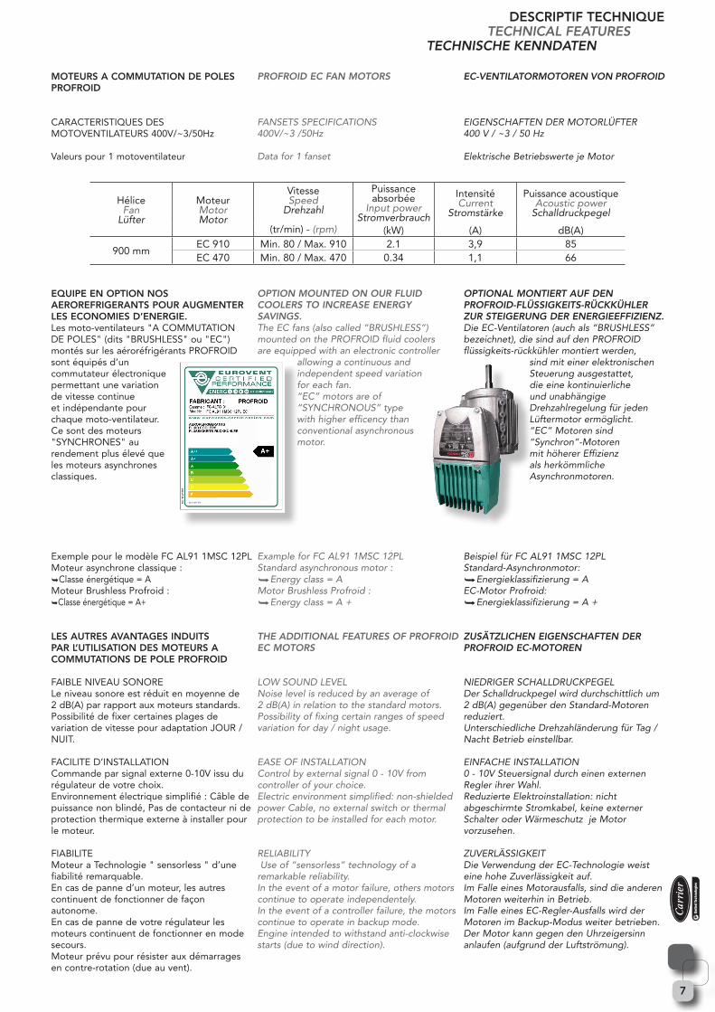
MOTEURS A COMMUTATION DE POLES PROFROID
CARACTERISTIQUES DES MOTOVENTILATEURS 400V/~3/50Hz
Valeurs pour 1 motoventilateur
EQUIPE EN OPTION NOS AEROREFRIGERANTS POUR AUGMENTER LES ECONOMIES D’ENERGIE.Les moto-ventilateurs "A COMMUTATION DE POLES" (dits "BRUSHLESS" ou "EC") montés sur les aéroréfrigérants PROFROID sont équipés d’un commutateur électronique permettant une variation de vitesse continue et indépendante pour chaque moto-ventilateur.Ce sont des moteurs "SYNCHRONES" au rendement plus élevé que les moteurs asynchrones classiques.
Exemple pour le modèle FC AL91 1MSC 12PL Moteur asynchrone classique :Classe énergétique = AMoteur Brushless Profroid :Classe énergétique = A+
LES AUTRES AVANTAGES INDUITS PAR L’UTILISATION DES MOTEURS A COMMUTATIONS DE POLE PROFROID
FAIBLE NIVEAU SONORE Le niveau sonore est réduit en moyenne de 2 dB(A) par rapport aux moteurs standards.Possibilité de fixer certaines plages de variation de vitesse pour adaptation JOUR / NUIT.
FACILITE D’INSTALLATION Commande par signal externe 0-10V issu du régulateur de votre choix.Environnement électrique simplifié : Câble de puissance non blindé, Pas de contacteur ni de protection thermique externe à installer pour le moteur.
FIABILITEMoteur a Technologie " sensorless " d’une fiabilité remarquable.En cas de panne d’un moteur, les autres continuent de fonctionner de façon autonome. En cas de panne de votre régulateur les moteurs continuent de fonctionner en mode secours.Moteur prévu pour résister aux démarrages en contre-rotation (due au vent).
PROFROID EC FAN MOTORS
FANSETS SPECIFICATIONS 400V/~3 /50Hz
Data for 1 fanset
OPTION MOUNTED ON OUR FLUID COOLERS TO INCREASE ENERGY SAVINGS. TheECfans(alsocalled“BRUSHLESS”)mounted on the PROFROID fluid coolers are equipped with an electronic controller
allowing a continuous and independent speed variation for each fan. “EC”motorsareof“SYNCHRONOUS”typewith higher efficency than conventional asynchronous motor.
Example for FC AL91 1MSC 12PLStandard asynchronous motor : Energyclass=AMotor Brushless Profroid : Energyclass=A+
THE ADDITIONAL FEATURES OF PROFROID EC MOTORS
LOW SOUND LEVEL Noise level is reduced by an average of 2 dB(A) in relation to the standard motors.Possibility of fixing certain ranges of speed variation for day / night usage.
EASE OF INSTALLATION Control by external signal 0 - 10V from controller of your choice.Electric environment simplified: non-shielded power Cable, no external switch or thermal protection to be installed for each motor.
RELIABILITYUseof“sensorless”technologyofaremarkable reliability.In the event of a motor failure, others motors continue to operate independentely.In the event of a controller failure, the motors continue to operate in backup mode.Engine intended to withstand anti-clockwise starts (due to wind direction).
EC-VENTILATORMOTOREN VON PROFROID
EIGENSCHAFTEN DER MOTORLÜFTER400 V / ~3 / 50 Hz
Elektrische Betriebswerte je Motor
OPTIONAL MONTIERT AUF DEN PROFROID-FLÜSSIGKEITS-RÜCKKÜHLER ZUR STEIGERUNG DER ENERGIEEFFIZIENZ. DieEC-Ventilatoren(auchals“BRUSHLESS”bezeichnet), die sind auf den PROFROID flüssigkeits-rückkühler montiert werden,
sind mit einer elektronischen Steuerung ausgestattet, die eine kontinuierliche und unabhängige Drehzahlregelung für jeden Lüftermotor ermöglicht. “EC”Motorensind“Synchron”-Motorenmit höherer Effizienz als herkömmliche Asynchronmotoren.
Beispiel für FC AL91 1MSC 12PLStandard-Asynchronmotor:Energieklassifizierung=AEC-Motor Profroid: Energieklassifizierung=A+
ZUSÄTZLICHEN EIGENSCHAFTEN DER PROFROID EC-MOTOREN
NIEDRIGER SCHALLDRUCKPEGELDer Schalldruckpegel wird durchschittlich um 2 dB(A) gegenüber den Standard-Motoren reduziert.Unterschiedliche Drehzahländerung für Tag / Nacht Betrieb einstellbar.
EINFACHE INSTALLATION0 - 10V Steuersignal durch einen externen Regler ihrer Wahl.Reduzierte Elektroinstallation: nicht abgeschirmte Stromkabel, keine externer Schalter oder Wärmeschutz je Motor vorzusehen.
ZUVERLÄSSIGKEITDie Verwendung der EC-Technologie weist eine hohe Zuverlässigkeit auf.Im Falle eines Motorausfalls, sind die anderen Motoren weiterhin in Betrieb.Im Falle eines EC-Regler-Ausfalls wird der Motoren im Backup-Modus weiter betrieben.Der Motor kann gegen den Uhrzeigersinn anlaufen (aufgrund der Luftströmung).
DESCRIPTIF TECHNIQUETECHNICAL FEATURES
TECHNISCHE KENNDATEN
HéliceFan
Lüfter
MoteurMotorMotor
VitesseSpeed
Drehzahl
(tr/min) - (rpm)
Puissanceabsorbée
Input powerStromverbrauch
IntensitéCurrent
Stromstärke
Puissance acoustiqueAcoustic power
Schalldruckpegel
(kW) (A) dB(A)
900 mmEC 910 Min. 80 / Max. 910 2.1 3,9 85EC 470 Min. 80 / Max. 470 0.34 1,1 66
8
PRECAUTIONS D’INSTALLATIONLes aéroréfrigérants doivent être manutentionnés à l’aide d’un palonnier et doivent être placés sur un support (sol, châssis métallique, …) qui permette de recevoir les points d’appui prévus. Dans tous les cas, il convient de s’assurer que le support puisse supporter le poids total en charge, sans fléchir afin qu’après fixation, l’aéroréfrigérant soit de niveau dans un plan horizontal. Des aires de service doivent être prévues autour de l’appareil, rien ne doit gêner l’aspiration et le refoulement des ventilateurs (se référer à la notice de mise en service).Le plan des tuyauteries devra être tracé avec soin et les règles de montage devront être suivies. Les boîtes de raccordement sont équipées de bornes permettant le raccordement des moteurs de façon séparée.Contrôler le serrage des éléments vissés, notamment les fixations hélices, moteurs, grilles, etc.Lors du câblage des moteurs, s’assurer du bon sens de rotation. Le sens de l’air est : batterie moteur.Dans le cas de nettoyage par projection d’eau, la pression du jet doit être limitée à 3 bars maxi à une distance de 1,5 mètres mini (ne pas utiliser de détergents agressifs).D’une façon générale, il convient de se référer à la notice de mise en service avant toute installation d’un appareil.
ATTENTION RISQUE DE GELLorsque la température ambiante peut être inférieure à 0°C, l’utilisation d’eau additionnée d’antigel est impérative.Dans le cas d’emploi impératif d’eau sans antigel, et de température ambiante négative, une construction adaptée est nécessaire, nous consulter.Une batterie ne peut se vidanger totalement par simple ouverture des orifices de purge. Pour s’assurer de la vidange complète, il convient d’injecter plusieurs fois, de l’air sous pression pour chasser l’eau stagnante.
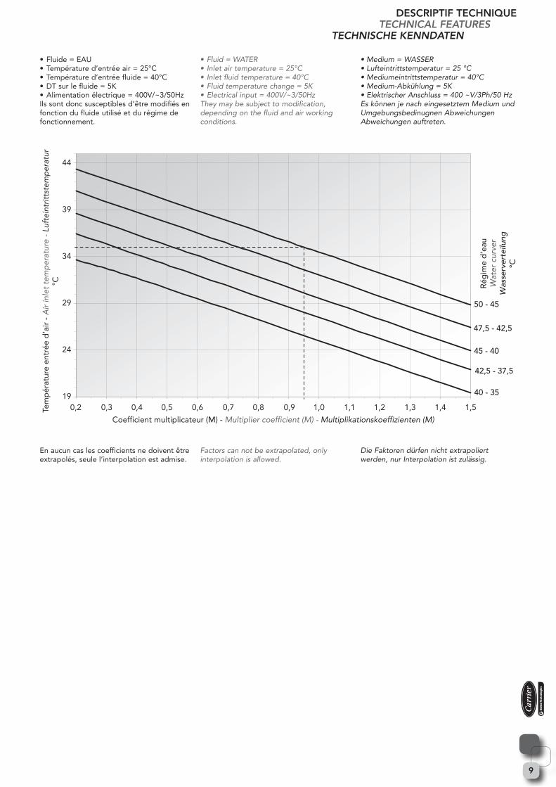
SELECTION RAPIDE Les puissances évacuées par les appareils, pour des conditions différentes des conditions standard, peuvent être estimées en multipliant les valeurs des tableaux de sélection par le coefficient obtenu sur le graphique ci dessous, les valeurs exactes ne peuvent être obtenues que par calcul (logiciel de sélection).Le circuitage et les diamètres de raccordement dépendent fortement des conditions de fonctionnement des aéroréfrigérants : DT sur le fluide, température entrée d’air, concentration d’additif antigel ...Les diamètres, annoncés dans les tableaux de sélection, sont donnés à titre indicatif; et ont été déterminés sous les conditions suivantes :
INSTALLATION GUIDANCEThe fluid coolers have to be moved carefully with a rudder bar and have to be installed on a support (ground, metallic frame …) which must allow to receive bearing point.In all case, the support has to be designed to sustain the full weight without any bending so that, after fitting, the fluid cooler is in horizontal plan level.
Space for servicing must be allowed around the equipment, the intake and exhaust of the fans must not be obstructed (refer to operating instructions leaflet).The pipework must be laid out with care and the installation instructions must be followed.The connection boxes are equipped with terminals permitting the connection of fans separately.Ensure that all screws are fully tightened, in particular fixings for the motors, fans, grids, etc...When connecting motors, be sure of the correct direction. The airflow direction is : coil motor.When cleaning by water spray, the pressure of the jet should be limited to 3 bars maximum at a distance of 1.5 m minimum (do not use aggressive detergents).Before any installation, please consult the fluid coolers IOM.
FREEZING HAZARDIf ambient temperature can fall below 0°C, it is imperative to add antifreeze to water.When water without antifreeze has to be used, and ambient temperature can fall below freezing, a specially adapted design is needed, please consult us.Coil cannot be emptied by simply opening the drain holes. To ensure complete draining, it is recommended to inject several times, pressured air in order to eject stagnant water.
QUICK SELECTIONCapacities for other conditions than standard, can be estimated just by multiplying the capacity given in the tables by the factor obtained in the following graph :The exact values can only be determined by using the selection software.Circuiting and connexion diameter depend of working conditions of the fluid cooler: fluid rate, air inlet temperature, anti-freezing liquid concentration …The diameters, announced in selection tables, are for indication; and have been determined under the following working conditions :
INSTALLATIONSVORSCHRIFTENDer Flüssigkeits-rückkühler ist vorsichtig mit Hilfe einer Traverse zu bewegen und muss auf einer entsprechenden Vorrichtung zur Aufnahmeder Auflagepunkte (Boden, Metallrahmen usw.) aufgebaut werden.Vergewissern Sie sich in jedem Falle, dass der Unterbau das Gesamtgewicht tragen kann, ohne dass es zu Verwindungen kommt,damit sich der Flüssigkeits-rückkühler nach entsprechender Befestigung in horizontalerEbene befindet.Um den Verflüssiger herum ist genügend Platz für entsprechende Reparaturarbeiten vorzusehen; der Luftein- und auslass der Lüfter darf nicht verstellt werden (siehe auch Inbetriebnahmehandbuch).Die Anordnung der Rohrleitungen ist sorgfältig vorzunehmen und dieInstallationsanweisungen sind einzuhalten.Der Klemmenkasten ist mit Anschlussklemmen ausgestattet, die den separaten Anschluss der Motoren ermöglichen.Überprüfen Sie, dass alle Schrauben angezogen sind, insbesondere die Befestigung der Ventilatoren, Motoren, Lüftergitter usw.Bei der Motorverdrahtung vergewissern Sie sich hinsichtlich der korrekten Drehrichtung. Die Richtung des Luftstroms ist :Verflüssigerpaket Motor.Wird der Verflüssiger mit Wasser gereinigt, muss der Druck des Wasserstrahlsauf maximal 3 bar bei einem Mindestabstand von 1,5 m begrenzt werden (verwenden Sie keine aggressiven Reinigungsmittel).Vor jeglicher Inbetriebnahmetätigkeit lesen Sie in jedem Falle das Handbuch zur Inbetriebnahme.
GEFAHR DES EINFRIERENSWenn die Umgebungstemperatur unter 0 ° C fällt, muss Frostschutzmittel in das Medium Wasser hinzufügt werden.Wenn das Wasser ohne Frostschutzmittel verwendet werden muss und die Umgebungstemperatur unter den Gefrierpunkt fallen kann, ist ein speziell angepasstes Design notwendig. Bitte kontaktieren Sie uns. Das Wärmetauscherpaket kann nicht durch Öffnen der Ablauflöcher entleert werden. Um eine vollständige Entleerung zu erreichen, empfehlen wir, mehrmals mit Druckluft die Das Paket druchzublasen, um stehendes Wasser zu entfernen.
SCHNELLAUSWAHLEine von dem Standardwert (siehe Leistungstabellen) abweichende Leistung kann durch Multiplikation der Nennleistung mit dem Korrekturfaktor, siehe nachfolgende Grafik, annähernd ermittelt werden.Die genauen Leistungsangaben können nur durch die Auswahl-Software ermittelt werden.Rohrverschaltung, Anzahl der Pässe und Anschluss sind von den Arbeitsbedingungen der Flüssigkeitsrückkühler abhängig: Medium-Volumenstrom, Konzentration des Frostschutzmittels im Medium, Lufteintrittstemperatur, ...Die angegebenenDurchmesser in den Auswahltabellen sind Katalogdaten und beziehen sich auf folgende Arbeitsbedingungen:
DESCRIPTIF TECHNIQUETECHNICAL FEATURES
TECHNISCHE KENNDATEN
9
• Fluide = EAU• Température d’entrée air = 25°C• Température d’entrée fluide = 40°C• DT sur le fluide = 5K• Alimentation électrique = 400V/~3/50HzIls sont donc susceptibles d’être modifiés en fonction du fluide utilisé et du régime de fonctionnement.
En aucun cas les coefficients ne doivent être extrapolés, seule l’interpolation est admise.
•Fluid=WATER• Inletairtemperature=25°C• Inletfluidtemperature=40°C•Fluidtemperaturechange=5K•Electricalinput=400V/~3/50HzThey may be subject to modification, depending on the fluid and air working conditions.
Factors can not be extrapolated, only interpolation is allowed.
•Medium=WASSER•Lufteintrittstemperatur=25°C•Mediumeintrittstemperatur=40°C•Medium-Abkühlung=5K•ElektrischerAnschluss=400~V/3Ph/50HzEs können je nach eingesetztem Medium und Umgebungsbedinugnen Abweichungen Abweichungen auftreten.
Die Faktoren dürfen nicht extrapoliert werden, nur Interpolation ist zulässig.
40 - 35
42,5 - 37,5
45 - 40
47,5 - 42,5
50 - 45
19
24
29
34
39
44
0,2 0,3 0,4 0,5 0,6 0,7 0,8 0,9 1,11,0 1,2 1,3 1,4 1,5
Rég
ime
d’e
auW
ater
cur
ver
Was
serv
erte
ilung
°C
Coefficient multiplicateur (M) - Multiplier coefficient (M) - Multiplikationskoeffizienten (M)
Tem
pér
atur
e en
trée
d’a
ir -
Air
inle
t te
mp
erat
ure
- Lu
ftei
ntri
ttst
emp
erat
ur
°C
DESCRIPTIF TECHNIQUETECHNICAL FEATURES
TECHNISCHE KENNDATEN
10
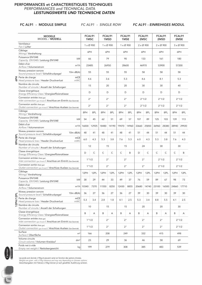
FC AL91 - MODULE SIMPLE FC AL91 - SINGLE ROW FC AL91 - EINREIHIGES MODUL
MODELEMODEL / MODELL
FCAL911MSC
FCAL911MSD
FCAL911MSE
FCAL912MSC
FCAL912MSD
FCAL912MSE
VentilateurFan / Lüfter
1 x Ø 900 1 x Ø 900 1 x Ø 900 2 x Ø 900 2 x Ø 900 3 x Ø 900
6PH
CâblageWiring / Verdrahtung
6PH 6PH 6PH 6PH 6PH 6PH
Puissance EN1048 CapacityEN1048/ LeistungEN1048
kW 66 79 90 133 161 180
Débit d'air Airflow / Volumenstrom
m³/h 23485 26950 28600 46970 53900 57200
Niveau pression sonore Sound pressure level / Schalldruckpegel
10m dB(A) 55 55 55 58 58 58
Perte de chargeHead pressure loss / Header Druckverlust
mCEmWC
4.6 3.6 5.3 4.6 8.1 5.3
Nombre de circuitsNumber of circuits / Anzahl der Schaltungen
15 20 20 30 30 40
Classe énergétique Energy Efficiency Class / Energieeffizienzklasse
D D D D D D
Connexion entrée (fileté gaz)
Inlet connection (gas thread) / Anschluss am Eintritt (Gas-Gewinde)2" 2" 2" 2"1/2 2"1/2 2"1/2
Connexion sortie (fileté gaz)
Outlet connection (gas thread) / Anschluss Auslass (Gas-Gewinde)2" 2" 2" 2"1/2 2"1/2 2"1/2
8PH
/8P
L
CâblageWiring / Verdrahtung
8PH 8PL 8PH 8PL 8PH 8PL 8PH 8PL 8PH 8PL 8PH 8PL
Puissance EN1048 CapacityEN1048/ LeistungEN1048
kW 54 45 62 51 69 57 107 89 125 103 139 113
Débit d'air Airflow / Volumenstrom
m³/h 16830 12925 18480 14190 19470 14960 33660 25850 36960 28380 38940 29920
Niveau pression sonore Sound pressure level / Schalldruckpegel
10m dB(A) 48 41 48 41 48 41 51 44 51 44 51 44
Perte de chargeHead pressure loss / Header Druckverlust
mCEmWC
6.0 4.3 5.3 3.8 7.6 5.3 6.0 4.3 5.3 3.8 7.6 4.3
Nombre de circuitsNumber of circuits / Anzahl der Schaltungen
12 15 15 24 30 30
Classe énergétique Energy Efficiency Class / Energieeffizienzklasse
D C C C C B D C C C C B
Connexion entrée (fileté gaz)
Inlet connection (gas thread) / Anschluss am Eintritt (Gas-Gewinde)1"1/2 2" 2" 2" 2"1/2 2"1/2
Connexion sortie (fileté gaz)
Outlet connection (gas thread) / Anschluss Auslass (Gas-Gewinde)1"1/2 2" 2" 2" 2"1/2 2"1/2
12P
H/1
2PL
CâblageWiring / Verdrahtung
12PH 12PL 12PH 12PL 12PH 12PL 12PH 12PL 12PH 12PL 12PH 12PL
Puissance EN1048 CapacityEN1048/ LeistungEN1048
kW 38 29 44 33 49 37 76 59 89 67 98 73
Débit d'air Airflow / Volumenstrom
m³/h 10340 7370 11550 8250 12430 8855 20680 14740 23100 16500 24860 17710
Niveau pression sonore Sound pressure level / Schalldruckpegel
10m dB(A) 36 27 36 27 36 27 39 30 39 30 39 30
Perte de chargeHead pressure loss / Header Druckverlust
mCEmWC
5.3 3.4 2.8 1.8 4.1 2.5 5.3 3.4 8.8 5.5 4.1 2.5
Nombre de circuitsNumber of circuits / Anzahl der Schaltungen
10 15 15 20 20 30
Classe énergétique Energy Efficiency Class / Energieeffizienzklasse
B A B A B A B A B A B A
Connexion entrée (fileté gaz)
Inlet connection (gas thread) / Anschluss am Eintritt (Gas-Gewinde)1"1/2 2" 2" 2" 2" 2"1/2
Connexion sortie (fileté gaz)
Outlet connection (gas thread) / Anschluss Auslass (Gas-Gewinde)1"1/2 2" 2" 2" 2" 2"1/2
SurfaceSurface / Oberfläche
m² 166 208 249 332 415 498
Volume circuitsCircuit volume / Volumen Kreislauf
dm³ 23 29 36 46 58 69
Poids net à videEmpty net weight / Nettoleergewicht
kg 199 279 308 385 483 539
PERFORMANCES et CARACTERISTIQUES TECHNIQUESPERFORMANCES and TECHNICAL DATA
LEISTUNGSWERTE UND TECHNISCHE DATEN
Les poids sont donnés ±15kg et peuvent varier en fonction des options choisies.Weights are given with ±15kg tolerance and may vary depending on choosen options.Gewichtsangaben (mit Toleranz ±15kg) können je nach gewählter Ausführung variieren.
11
PERFORMANCES et CARACTERISTIQUES TECHNIQUESPERFORMANCES and TECHNICAL DATA
LEISTUNGSWERTE UND TECHNISCHE DATEN
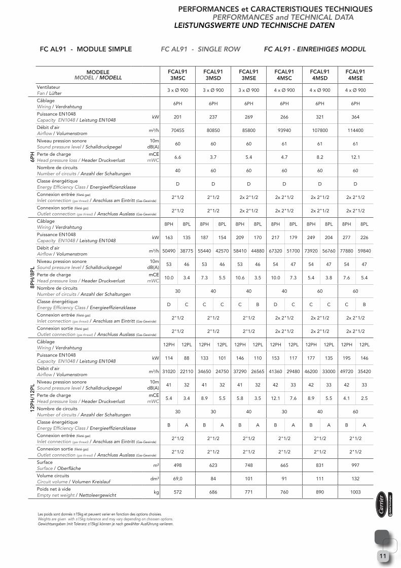
FC AL91 - MODULE SIMPLE FC AL91 - SINGLE ROW FC AL91 - EINREIHIGES MODUL
MODELEMODEL / MODELL
FCAL913MSC
FCAL913MSD
FCAL913MSE
FCAL914MSC
FCAL914MSD
FCAL914MSE
VentilateurFan / Lüfter
3 x Ø 900 3 x Ø 900 3 x Ø 900 4 x Ø 900 4 x Ø 900 4 x Ø 900
6PH
CâblageWiring / Verdrahtung
6PH 6PH 6PH 6PH 6PH 6PH
Puissance EN1048 CapacityEN1048/ LeistungEN1048
kW 201 237 269 266 321 364
Débit d'air Airflow / Volumenstrom
m³/h 70455 80850 85800 93940 107800 114400
Niveau pression sonore Sound pressure level / Schalldruckpegel
10m dB(A)
60 60 60 61 61 61
Perte de chargeHead pressure loss / Header Druckverlust
mCEmWC
6.6 3.7 5.4 4.7 8.2 12.1
Nombre de circuitsNumber of circuits / Anzahl der Schaltungen
40 60 60 60 60 60
Classe énergétique Energy Efficiency Class / Energieeffizienzklasse
D D D D D D
Connexion entrée (fileté gaz)
Inlet connection (gas thread) / Anschluss am Eintritt (Gas-Gewinde)2"1/2 2"1/2 2x 2"1/2 2x 2"1/2 2x 2"1/2 2x 2"1/2
Connexion sortie (fileté gaz)
Outlet connection (gas thread) / Anschluss Auslass (Gas-Gewinde)2"1/2 2"1/2 2x 2"1/2 2x 2"1/2 2x 2"1/2 2x 2"1/2
8PH
/8P
L
CâblageWiring / Verdrahtung
8PH 8PL 8PH 8PL 8PH 8PL 8PH 8PL 8PH 8PL 8PH 8PL
Puissance EN1048 CapacityEN1048/ LeistungEN1048
kW 163 135 187 154 209 170 217 179 249 204 277 226
Débit d'air Airflow / Volumenstrom
m³/h 50490 38775 55440 42570 58410 44880 67320 51700 73920 56760 77880 59840
Niveau pression sonore Sound pressure level / Schalldruckpegel
10m dB(A)
53 46 53 46 53 46 54 47 54 47 54 47
Perte de chargeHead pressure loss / Header Druckverlust
mCEmWC
10.0 3.4 7.3 5.5 10.6 3.5 10.0 7.3 5.4 3.8 7.6 5.4
Nombre de circuitsNumber of circuits / Anzahl der Schaltungen
30 40 40 40 60 60
Classe énergétique Energy Efficiency Class / Energieeffizienzklasse
D C C C C B D C C C C B
Connexion entrée (fileté gaz)
Inlet connection (gas thread) / Anschluss am Eintritt (Gas-Gewinde)2"1/2 2"1/2 2"1/2 2x 2"1/2 2x 2"1/2 2x 2"1/2
Connexion sortie (fileté gaz)
Outlet connection (gas thread) / Anschluss Auslass (Gas-Gewinde)2"1/2 2"1/2 2"1/2 2x 2"1/2 2x 2"1/2 2x 2"1/2
12P
H/1
2PL
CâblageWiring / Verdrahtung
12PH 12PL 12PH 12PL 12PH 12PL 12PH 12PL 12PH 12PL 12PH 12PL
Puissance EN1048 CapacityEN1048/ LeistungEN1048
kW 114 88 133 101 146 110 153 117 177 135 195 146
Débit d'air Airflow / Volumenstrom
m³/h 31020 22110 34650 24750 37290 26565 41360 29480 46200 33000 49720 35420
Niveau pression sonore Sound pressure level / Schalldruckpegel
10m dB(A)
41 32 41 32 41 32 42 33 42 33 42 33
Perte de chargeHead pressure loss / Header Druckverlust
mCEmWC
5.4 3.4 8.9 5.5 5.8 3.5 12.1 7.6 8.9 5.5 4.1 2.5
Nombre de circuitsNumber of circuits / Anzahl der Schaltungen
30 30 40 30 40 60
Classe énergétique Energy Efficiency Class / Energieeffizienzklasse
B A B A B A B A B A B A
Connexion entrée (fileté gaz)
Inlet connection (gas thread) / Anschluss am Eintritt (Gas-Gewinde)2"1/2 2"1/2 2"1/2 2"1/2 2"1/2 2"1/2
Connexion sortie (fileté gaz)
Outlet connection (gas thread) / Anschluss Auslass (Gas-Gewinde)2"1/2 2"1/2 2"1/2 2"1/2 2"1/2 2"1/2
SurfaceSurface / Oberfläche
m² 498 623 748 665 831 997
Volume circuitsCircuit volume / Volumen Kreislauf
dm³ 69,0 84 101 91 111 132
Poids net à videEmpty net weight / Nettoleergewicht
kg 572 686 771 760 890 1003
Les poids sont donnés ±15kg et peuvent varier en fonction des options choisies.Weights are given with ±15kg tolerance and may vary depending on choosen options.Gewichtsangaben (mit Toleranz ±15kg) können je nach gewählter Ausführung variieren.
12
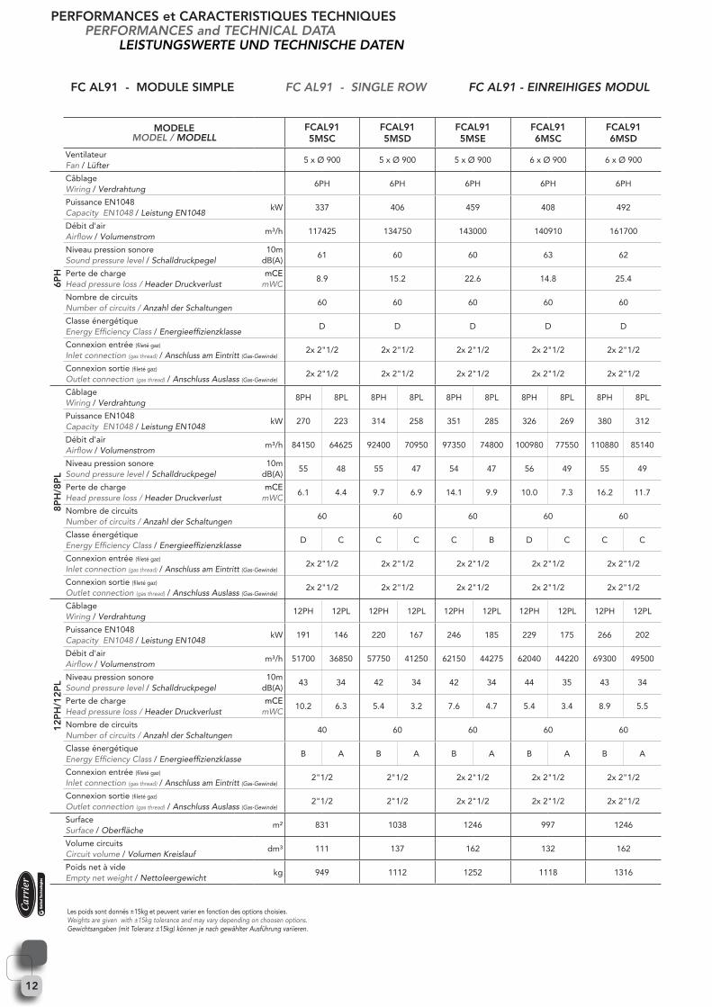
FC AL91 - MODULE SIMPLE FC AL91 - SINGLE ROW FC AL91 - EINREIHIGES MODUL
MODELEMODEL / MODELL
FCAL915MSC
FCAL915MSD
FCAL915MSE
FCAL916MSC
FCAL916MSD
VentilateurFan / Lüfter
5 x Ø 900 5 x Ø 900 5 x Ø 900 6 x Ø 900 6 x Ø 900
6PH
CâblageWiring / Verdrahtung
6PH 6PH 6PH 6PH 6PH
Puissance EN1048 CapacityEN1048/ LeistungEN1048
kW 337 406 459 408 492
Débit d'air Airflow / Volumenstrom
m³/h 117425 134750 143000 140910 161700
Niveau pression sonore Sound pressure level / Schalldruckpegel
10m dB(A)
61 60 60 63 62
Perte de chargeHead pressure loss / Header Druckverlust
mCEmWC
8.9 15.2 22.6 14.8 25.4
Nombre de circuitsNumber of circuits / Anzahl der Schaltungen
60 60 60 60 60
Classe énergétique Energy Efficiency Class / Energieeffizienzklasse
D D D D D
Connexion entrée (fileté gaz)
Inlet connection (gas thread) / Anschluss am Eintritt (Gas-Gewinde)2x 2"1/2 2x 2"1/2 2x 2"1/2 2x 2"1/2 2x 2"1/2
Connexion sortie (fileté gaz)
Outlet connection (gas thread) / Anschluss Auslass (Gas-Gewinde)2x 2"1/2 2x 2"1/2 2x 2"1/2 2x 2"1/2 2x 2"1/2
8PH
/8P
L
CâblageWiring / Verdrahtung
8PH 8PL 8PH 8PL 8PH 8PL 8PH 8PL 8PH 8PL
Puissance EN1048 CapacityEN1048/ LeistungEN1048
kW 270 223 314 258 351 285 326 269 380 312
Débit d'air Airflow / Volumenstrom
m³/h 84150 64625 92400 70950 97350 74800 100980 77550 110880 85140
Niveau pression sonore Sound pressure level / Schalldruckpegel
10m dB(A)
55 48 55 47 54 47 56 49 55 49
Perte de chargeHead pressure loss / Header Druckverlust
mCEmWC
6.1 4.4 9.7 6.9 14.1 9.9 10.0 7.3 16.2 11.7
Nombre de circuitsNumber of circuits / Anzahl der Schaltungen
60 60 60 60 60
Classe énergétique Energy Efficiency Class / Energieeffizienzklasse
D C C C C B D C C C
Connexion entrée (fileté gaz)
Inlet connection (gas thread) / Anschluss am Eintritt (Gas-Gewinde)2x 2"1/2 2x 2"1/2 2x 2"1/2 2x 2"1/2 2x 2"1/2
Connexion sortie (fileté gaz)
Outlet connection (gas thread) / Anschluss Auslass (Gas-Gewinde)2x 2"1/2 2x 2"1/2 2x 2"1/2 2x 2"1/2 2x 2"1/2
12P
H/1
2PL
CâblageWiring / Verdrahtung
12PH 12PL 12PH 12PL 12PH 12PL 12PH 12PL 12PH 12PL
Puissance EN1048 CapacityEN1048/ LeistungEN1048
kW 191 146 220 167 246 185 229 175 266 202
Débit d'air Airflow / Volumenstrom
m³/h 51700 36850 57750 41250 62150 44275 62040 44220 69300 49500
Niveau pression sonore Sound pressure level / Schalldruckpegel
10m dB(A)
43 34 42 34 42 34 44 35 43 34
Perte de chargeHead pressure loss / Header Druckverlust
mCEmWC
10.2 6.3 5.4 3.2 7.6 4.7 5.4 3.4 8.9 5.5
Nombre de circuitsNumber of circuits / Anzahl der Schaltungen
40 60 60 60 60
Classe énergétique Energy Efficiency Class / Energieeffizienzklasse
B A B A B A B A B A
Connexion entrée (fileté gaz)
Inlet connection (gas thread) / Anschluss am Eintritt (Gas-Gewinde)2"1/2 2"1/2 2x 2"1/2 2x 2"1/2 2x 2"1/2
Connexion sortie (fileté gaz)
Outlet connection (gas thread) / Anschluss Auslass (Gas-Gewinde)2"1/2 2"1/2 2x 2"1/2 2x 2"1/2 2x 2"1/2
SurfaceSurface / Oberfläche
m² 831 1038 1246 997 1246
Volume circuitsCircuit volume / Volumen Kreislauf
dm³ 111 137 162 132 162
Poids net à videEmpty net weight / Nettoleergewicht
kg 949 1112 1252 1118 1316
PERFORMANCES et CARACTERISTIQUES TECHNIQUESPERFORMANCES and TECHNICAL DATA
LEISTUNGSWERTE UND TECHNISCHE DATEN
Les poids sont donnés ±15kg et peuvent varier en fonction des options choisies.Weights are given with ±15kg tolerance and may vary depending on choosen options.Gewichtsangaben (mit Toleranz ±15kg) können je nach gewählter Ausführung variieren.
13
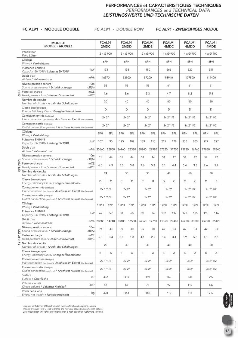
FC AL91 - MODULE DOUBLE FC AL91 - DOUBLE ROW FC AL91 - ZWEIREIHIGES MODUL
MODELEMODEL / MODELL
FCAL912MDC
FCAL912MDD
FCAL912MDE
FCAL914MDC
FCAL914MDD
FCAL914MDE
VentilateurFan / Lüfter
2 x Ø 900 2 x Ø 900 2 x Ø 900 4 x Ø 900 4 x Ø 900 4 x Ø 900
6PH
CâblageWiring / Verdrahtung
6PH 6PH 6PH 6PH 6PH 6PH
Puissance EN1048 CapacityEN1048/ LeistungEN1048
kW 133 158 180 266 322 359
Débit d'air Airflow / Volumenstrom
m³/h 46970 53900 57200 93940 107800 114400
Niveau pression sonore Sound pressure level / Schalldruckpegel
10m dB(A)
58 58 58 61 61 61
Perte de chargeHead pressure loss / Header Druckverlust
mCEmWC
4.6 3.6 5.3 4.7 8.2 5.4
Nombre de circuitsNumber of circuits / Anzahl der Schaltungen
30 40 40 60 60 80
Classe énergétique Energy Efficiency Class / Energieeffizienzklasse
D D D D D D
Connexion entrée (fileté gaz)
Inlet connection (gas thread) / Anschluss am Eintritt (Gas-Gewinde)2x 2" 2x 2" 2x 2" 2x 2"1/2 2x 2"1/2 2x 2"1/2
Connexion sortie (fileté gaz)
Outlet connection (gas thread) / Anschluss Auslass (Gas-Gewinde)2x 2" 2x 2" 2x 2" 2x 2"1/2 2x 2"1/2 2x 2"1/2
8PH
/8P
L
CâblageWiring / Verdrahtung
8PH 8PL 8PH 8PL 8PH 8PL 8PH 8PL 8PH 8PL 8PH 8PL
Puissance EN1048 CapacityEN1048/ LeistungEN1048
kW 107 90 125 102 139 113 215 178 250 205 277 227
Débit d'air Airflow / Volumenstrom
m³/h 33660 25850 36960 28380 38940 29920 67320 51700 73920 56760 77880 59840
Niveau pression sonore Sound pressure level / Schalldruckpegel
10m dB(A)
51 44 51 44 51 44 54 47 54 47 54 47
Perte de chargeHead pressure loss / Header Druckverlust
mCEmWC
6.0 4.3 5.3 3.8 7.6 5.3 6.1 4.4 5.4 3.8 7.6 5.4
Nombre de circuitsNumber of circuits / Anzahl der Schaltungen
24 30 30 48 60 60
Classe énergétique Energy Efficiency Class / Energieeffizienzklasse
D C C C C B D C C C C B
Connexion entrée (fileté gaz)
Inlet connection (gas thread) / Anschluss am Eintritt (Gas-Gewinde)2x 1"1/2 2x 2" 2x 2" 2x 2" 2x 2"1/2 2x 2"1/2
Connexion sortie (fileté gaz)
Outlet connection (gas thread) / Anschluss Auslass (Gas-Gewinde)2x 1"1/2 2x 2" 2x 2" 2x 2" 2x 2"1/2 2x 2"1/2
12P
H/1
2PL
CâblageWiring / Verdrahtung
12PH 12PL 12PH 12PL 12PH 12PL 12PH 12PL 12PH 12PL 12PH 12PL
Puissance EN1048 CapacityEN1048/ LeistungEN1048
kW 76 59 88 66 98 74 152 117 178 135 195 146
Débit d'air Airflow / Volumenstrom
m³/h 20680 14740 23100 16500 24860 17710 41360 29480 46200 33000 49720 35420
Niveau pression sonore Sound pressure level / Schalldruckpegel
10m dB(A)
39 30 39 30 39 30 42 33 42 33 42 33
Perte de chargeHead pressure loss / Header Druckverlust
mCEmWC
5.3 3.4 2.8 1.8 4.1 2.5 5.4 3.4 8.9 5.5 4.1 2.5
Nombre de circuitsNumber of circuits / Anzahl der Schaltungen
20 30 30 40 40 60
Classe énergétique Energy Efficiency Class / Energieeffizienzklasse
B A B A B A B A B A B A
Connexion entrée (fileté gaz)
Inlet connection (gas thread) / Anschluss am Eintritt (Gas-Gewinde)2x 1"1/2 2x 2" 2x 2" 2x 2" 2x 2" 2x 2"1/2
Connexion sortie (fileté gaz)
Outlet connection (gas thread) / Anschluss Auslass (Gas-Gewinde)2x 1"1/2 2x 2" 2x 2" 2x 2" 2x 2" 2x 2"1/2
SurfaceSurface / Oberfläche
m² 332 415 498 660 831 997
Volume circuitsCircuit volume / Volumen Kreislauf
dm³ 47 57 71 92 117 137
Poids net à videEmpty net weight / Nettoleergewicht
kg 398 443 482 712 811 917
PERFORMANCES et CARACTERISTIQUES TECHNIQUESPERFORMANCES and TECHNICAL DATA
LEISTUNGSWERTE UND TECHNISCHE DATEN
Les poids sont donnés ±15kg et peuvent varier en fonction des options choisies.Weights are given with ±15kg tolerance and may vary depending on choosen options.Gewichtsangaben (mit Toleranz ±15kg) können je nach gewählter Ausführung variieren.
14
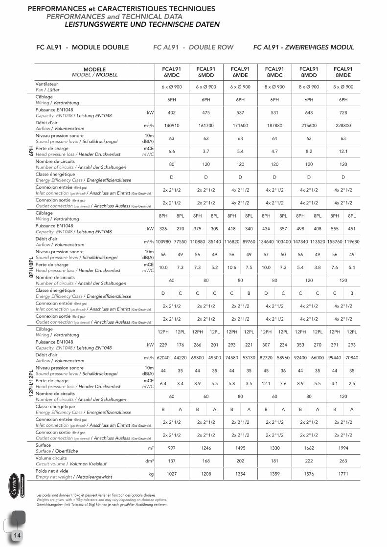
MODELEMODEL / MODELL
FCAL916MDC
FCAL916MDD
FCAL916MDE
FCAL918MDC
FCAL918MDD
FCAL918MDE
VentilateurFan / Lüfter
6 x Ø 900 6 x Ø 900 6 x Ø 900 8 x Ø 900 8 x Ø 900 8 x Ø 900
6PH
CâblageWiring / Verdrahtung
6PH 6PH 6PH 6PH 6PH 6PH
Puissance EN1048 CapacityEN1048/ LeistungEN1048
kW 402 475 537 531 643 728
Débit d'air Airflow / Volumenstrom
m³/h 140910 161700 171600 187880 215600 228800
Niveau pression sonore Sound pressure level / Schalldruckpegel
10m dB(A)
63 63 63 64 63 63
Perte de chargeHead pressure loss / Header Druckverlust
mCEmWC
6.6 3.7 5.4 4.7 8.2 12.1
Nombre de circuitsNumber of circuits / Anzahl der Schaltungen
80 120 120 120 120 120
Classe énergétique Energy Efficiency Class / Energieeffizienzklasse
D D D D D D
Connexion entrée (fileté gaz)
Inlet connection (gas thread) / Anschluss am Eintritt (Gas-Gewinde)2x 2"1/2 2x 2"1/2 4x 2"1/2 4x 2"1/2 4x 2"1/2 4x 2"1/2
Connexion sortie (fileté gaz)
Outlet connection (gas thread) / Anschluss Auslass (Gas-Gewinde)2x 2"1/2 2x 2"1/2 4x 2"1/2 4x 2"1/2 4x 2"1/2 4x 2"1/2
8PH
/8P
L
CâblageWiring / Verdrahtung
8PH 8PL 8PH 8PL 8PH 8PL 8PH 8PL 8PH 8PL 8PH 8PL
Puissance EN1048 CapacityEN1048/ LeistungEN1048
kW 326 270 375 309 418 340 434 357 498 408 555 451
Débit d'air Airflow / Volumenstrom
m³/h 100980 77550 110880 85140 116820 89760 134640 103400 147840 113520 155760 119680
Niveau pression sonore Sound pressure level / Schalldruckpegel
10m dB(A)
56 49 56 49 56 49 57 50 56 49 56 49
Perte de chargeHead pressure loss / Header Druckverlust
mCEmWC
10.0 7.3 7.3 5.2 10.6 7.5 10.0 7.3 5.4 3.8 7.6 5.4
Nombre de circuitsNumber of circuits / Anzahl der Schaltungen
60 80 80 80 120 120
Classe énergétique Energy Efficiency Class / Energieeffizienzklasse
D C C C C B D C C C C B
Connexion entrée (fileté gaz)
Inlet connection (gas thread) / Anschluss am Eintritt (Gas-Gewinde)2x 2"1/2 2x 2"1/2 2x 2"1/2 4x 2"1/2 4x 2"1/2 4x 2"1/2
Connexion sortie (fileté gaz)
Outlet connection (gas thread) / Anschluss Auslass (Gas-Gewinde)2x 2"1/2 2x 2"1/2 2x 2"1/2 4x 2"1/2 4x 2"1/2 4x 2"1/2
12P
H/1
2PL
CâblageWiring / Verdrahtung
12PH 12PL 12PH 12PL 12PH 12PL 12PH 12PL 12PH 12PL 12PH 12PL
Puissance EN1048 CapacityEN1048/ LeistungEN1048
kW 229 176 266 201 293 221 307 234 353 270 391 293
Débit d'air Airflow / Volumenstrom
m³/h 62040 44220 69300 49500 74580 53130 82720 58960 92400 66000 99440 70840
Niveau pression sonore Sound pressure level / Schalldruckpegel
10m dB(A)
44 35 44 35 44 35 45 36 44 35 44 35
Perte de chargeHead pressure loss / Header Druckverlust
mCEmWC
6.4 3.4 8.9 5.5 5.8 3.5 12.1 7.6 8.9 5.5 4.1 2.5
Nombre de circuitsNumber of circuits / Anzahl der Schaltungen
60 60 80 60 80 120
Classe énergétique Energy Efficiency Class / Energieeffizienzklasse
B A B A B A B A B A B A
Connexion entrée (fileté gaz)
Inlet connection (gas thread) / Anschluss am Eintritt (Gas-Gewinde)2x 2"1/2 2x 2"1/2 2x 2"1/2 2x 2"1/2 2x 2"1/2 2x 2"1/2
Connexion sortie (fileté gaz)
Outlet connection (gas thread) / Anschluss Auslass (Gas-Gewinde)2x 2"1/2 2x 2"1/2 2x 2"1/2 2x 2"1/2 2x 2"1/2 2x 2"1/2
SurfaceSurface / Oberfläche
m² 997 1246 1495 1330 1662 1994
Volume circuitsCircuit volume / Volumen Kreislauf
dm³ 137 168 202 181 222 263
Poids net à videEmpty net weight / Nettoleergewicht
kg 1027 1208 1354 1359 1576 1771
FC AL91 - MODULE DOUBLE FC AL91 - DOUBLE ROW FC AL91 - ZWEIREIHIGES MODUL
PERFORMANCES et CARACTERISTIQUES TECHNIQUESPERFORMANCES and TECHNICAL DATA
LEISTUNGSWERTE UND TECHNISCHE DATEN
Les poids sont donnés ±15kg et peuvent varier en fonction des options choisies.Weights are given with ±15kg tolerance and may vary depending on choosen options.Gewichtsangaben (mit Toleranz ±15kg) können je nach gewählter Ausführung variieren.

15
MODELEMODEL / MODELL
FCAL9110MDC
FCAL9110MDD
FCAL9110MDE
FCAL9112MDC
FCAL9112MDD
VentilateurFan / Lüfter
10 x Ø 900 10 x Ø 900 10 x Ø 900 12 x Ø 900 12 x Ø 900
6PH
CâblageWiring / Verdrahtung
6PH 6PH 6PH 6PH 6PH
Puissance EN1048 CapacityEN1048/ LeistungEN1048
kW 674 812 918 816 984
Débit d'air Airflow / Volumenstrom
m³/h 234850 269500 286000 281820 323400
Niveau pression sonore Sound pressure level / Schalldruckpegel
10m dB(A)
64 64 64 65 65
Perte de chargeHead pressure loss / Header Druckverlust
mCEmWC
8.9 15.2 22.6 14.8 25.4
Nombre de circuitsNumber of circuits / Anzahl der Schaltungen
120 120 120 120 120
Classe énergétique Energy Efficiency Class / Energieeffizienzklasse
D D D D D
Connexion entrée (fileté gaz)
Inlet connection (gas thread) / Anschluss am Eintritt (Gas-Gewinde)4x 2"1/2 4x 2"1/2 4x 2"1/2 4x 2"1/2 4x 2"1/2
Connexion sortie (fileté gaz)
Outlet connection (gas thread) / Anschluss Auslass (Gas-Gewinde)4x 2"1/2 4x 2"1/2 4x 2"1/2 4x 2"1/2 4x 2"1/2
8PH
/8P
L
CâblageWiring / Verdrahtung
8PH 8PL 8PH 8PL 8PH 8PL 8PH 8PL 8PH 8PL
Puissance EN1048 CapacityEN1048/ LeistungEN1048
kW 539 445 629 516 701 570 652 537 760 623
Débit d'air Airflow / Volumenstrom
m³/h 168300 129250 184800 141900 194700 149600 201960 155100 221760 170280
Niveau pression sonore Sound pressure level / Schalldruckpegel
10m dB(A)
57 50 57 50 57 50 58 51 58 51
Perte de chargeHead pressure loss / Header Druckverlust
mCEmWC
6.1 4.4 9.7 6.9 14.1 9.9 10.0 7.3 16.2 11.7
Nombre de circuitsNumber of circuits / Anzahl der Schaltungen
120 120 120 120 120
Classe énergétique Energy Efficiency Class / Energieeffizienzklasse
D C C C C B D C C C
Connexion entrée (fileté gaz)
Inlet connection (gas thread) / Anschluss am Eintritt (Gas-Gewinde)4x 2"1/2 4x 2"1/2 4x 2"1/2 4x 2"1/2 4x 2"1/2
Connexion sortie (fileté gaz)
Outlet connection (gas thread) / Anschluss Auslass (Gas-Gewinde)4x 2"1/2 4x 2"1/2 4x 2"1/2 4x 2"1/2 4x 2"1/2
12P
H/1
2PL
CâblageWiring / Verdrahtung
12PH 12PL 12PH 12PL 12PH 12PL 12PH 12PL 12PH 12PL
Puissance EN1048 CapacityEN1048/ LeistungEN1048
kW 383 293 439 334 492 369 457 350 531 404
Débit d'air Airflow / Volumenstrom
m³/h 103400 73700 115500 82500 124300 88550 124080 88440 138600 99000
Niveau pression sonore Sound pressure level / Schalldruckpegel
10m dB(A)
45 36 45 36 45 36 46 37 46 37
Perte de chargeHead pressure loss / Header Druckverlust
mCEmWC
10.2 6.3 5.4 3.2 7.6 4.7 5.4 3.4 8.9 5.5
Nombre de circuitsNumber of circuits / Anzahl der Schaltungen
80 120 120 120 120
Classe énergétique Energy Efficiency Class / Energieeffizienzklasse
B A B A B A B A B A
Connexion entrée (fileté gaz)
Inlet connection (gas thread) / Anschluss am Eintritt (Gas-Gewinde)2x 2"1/2 2x 2"1/2 4x 2"1/2 4x 2"1/2 4x 2"1/2
Connexion sortie (fileté gaz)
Outlet connection (gas thread) / Anschluss Auslass (Gas-Gewinde)2x 2"1/2 2x 2"1/2 4x 2"1/2 4x 2"1/2 4x 2"1/2
SurfaceSurface / Oberfläche
m² 1662 2077 2492 1994 2492
Volume circuitsCircuit volume / Volumen Kreislauf
dm³ 222 273 324 263 324
Poids net à videEmpty net weight / Nettoleergewicht
kg 1692 1977 2218 2012 2349
FC AL91 - MODULE DOUBLE FC AL91 - DOUBLE ROW FC AL91 - ZWEIREIHIGES MODUL
PERFORMANCES et CARACTERISTIQUES TECHNIQUESPERFORMANCES and TECHNICAL DATA
LEISTUNGSWERTE UND TECHNISCHE DATEN
Les poids sont donnés ±15kg et peuvent varier en fonction des options choisies.Weights are given with ±15kg tolerance and may vary depending on choosen options.Gewichtsangaben (mit Toleranz ±15kg) können je nach gewählter Ausführung variieren.
16
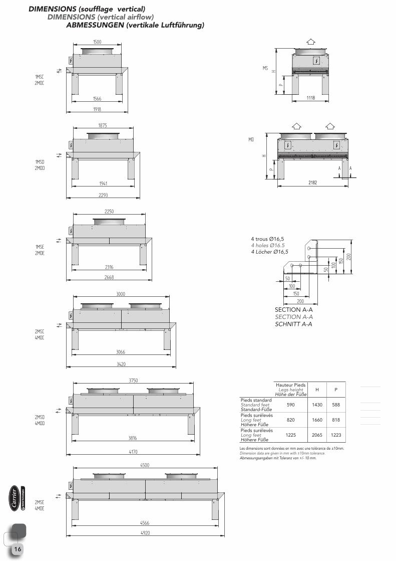
DIMENSIONS (soufflage vertical)DIMENSIONS (vertical airflow)
ABMESSUNGEN (vertikale Luftführung)
∅16.5
Les dimensions sont données en mm avec une tolérance de ±10mm. Dimension data are given in mm with ±10mm tolerance. Abmessungsangaben mit Toleranz von +/- 10 mm.
4 trous Ø16,54 holes Ø16.54 Löcher Ø16,5
SECTION A-ASECTION A-ASCHNITT A-A
Hauteur PiedsLegs height
Höhe der FüßeH P
Pieds standardStandard feet Standard-Füße
590 1430 588
Pieds surélevésLong feetHöhere Füße
820 1660 818
Pieds surélevésLong feetHöhere Füße
1225 2065 1223
1118
2182
17
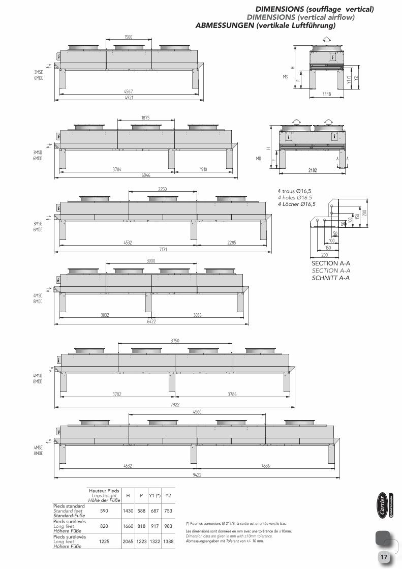
DIMENSIONS (soufflage vertical)DIMENSIONS (vertical airflow)
ABMESSUNGEN (vertikale Luftführung)
∅16.5
Hauteur PiedsLegs height
Höhe der FüßeH P Y1 (*) Y2
Pieds standardStandard feet Standard-Füße
590 1430 588 687 753
Pieds surélevésLong feetHöhere Füße
820 1660 818 917 983
Pieds surélevésLong feetHöhere Füße
1225 2065 1223 1322 1388
Les dimensions sont données en mm avec une tolérance de ±10mm. Dimension data are given in mm with ±10mm tolerance. Abmessungsangaben mit Toleranz von +/- 10 mm.
(*) Pour les connexions Ø 2"5/8, la sortie est orientée vers le bas.
4 trous Ø16,54 holes Ø16.54 Löcher Ø16,5
SECTION A-ASECTION A-ASCHNITT A-A
1118
2182

18
DIMENSIONS (soufflage vertical)DIMENSIONS (vertical airflow)
ABMESSUNGEN (vertikale Luftführung)
∅16.5
Hauteur PiedsLegs height
Höhe der FüßeH P
Y1 (*)
Y2
Pieds standardStandard feet Standard-Füße
590 1430 588 687 753
Pieds surélevésLong feetHöhere Füße
820 1660 818 917 983
Pieds surélevésLong feetHöhere Füße
1225 2065 1223 1322 1388
Les dimensions sont données en mm avec une tolérance de ±10mm. Dimension data are given in mm with ±10mm tolerance. Abmessungsangaben mit Toleranz von +/- 10 mm.
4 trous Ø16,54 holes Ø16.54 Löcher Ø16,5
SECTION A-ASECTION A-ASCHNITT A-A
11182182
19
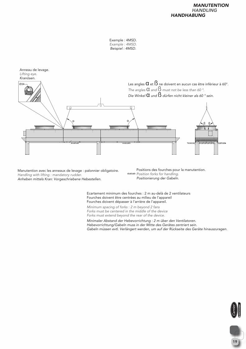
Ø34
α αß ß
Manutention avec les anneaux de levage : palonnier obligatoire.Handling with lifting : mandatory rudder.Anheben mittels Kran: Vorgeschriebene Hebestellen.
Positions des fourches pour la manutention.Position forks for handling.Positionierung der Gabeln.
Les angles α et ß ne doivent en aucun cas être inférieur à 60°.
The angles α and ß must not be less than 60 °.
Die Winkel α und ß dürfen nicht kleiner als 60 ° sein.
Anneau de levage.Lifting eye.Kranösen.
Exemple : 4MSD.Example : 4MSD.Beispiel : 4MSD.
MANUTENTIONHANDLING
HANDHABUNG
Ecartement minimum des fourches : 2 m au-delà de 2 ventilateursFourches doivent être centrées au milieu de l'appareilFourches doivent dépasser à l'arrière de l'appareil.
Minimum spacing of forks : 2 m beyond 2 fansForks must be centered in the middle of the deviceForks must extend beyond the rear of the device.
Minimaler Abstand der Hebevorrichtung : 2 m über den Ventilatoren.Hebevorrichtung/Gabeln muss in der Mitte des Gerätes zentriert sein.Gabeln müssen evtl. Verlängert werden, um auf der Rückseite des Geräte hinauszuragen.

178, rue du Fauge - Z.I. Les Paluds - BP 1152 13782 Aubagne Cedex - France - Site Internet : www.profroid.comTél. +33 4 42 18 05 00 - Fax +33 4 42 18 05 02 - Fax Export : +33 4 42 18 05 09
Le fabricant se réserve le droit de procéder à toutes modification sans préavis.L’image montrée en page de couverture est uniquement à titre indicatif et n’est pas contractuelle
Manufacturer reserves the right to change any product specifications without notice.The cover photo is solely for illustration purposes and not contractually binding.
English version is a translation of the french original version which prevails in all cases.
Der Hersteller behält sich das Recht zu kurzfristigen Änderungen vor.Die Abbildung auf der Titelseite ist unverbindlich und dient lediglich der allgemeinen Information.
_CAR_3150Doc. Réf : JE_ALTO
Recommended