Embed Size (px)
Citation preview

5 3 5 0T r a n s m e t t e u r PROFIBUS PA / Fieldbus FOUNDA TION
N o 5 3 5 0 V 1 1 3 - F RA partir de no. de série 1 5 2 0 1 8 4 3 6

1650
PR electronics A/S tilbyder et bredt program af analoge og digitale signalbehandlingsmoduler til industriel automation. Programmet består af Isolatorer, Displays, Ex-barrierer, Temperaturtransmittere, Universaltransmittere mfl. Vi har modulerne, du kan stole på i selv barske miljøer med elektrisk støj, vibrationer og temperaturudsving, og alle produkter opfylder de strengeste internationale standarder. Vores motto »Signals the Best« er indbegrebet af denne filosofi – og din garanti for kvalitet.
PR electronics A/S offers a wide range of analogue and digital signal conditioning devices for industrial automation. The product range includes Isolators, Displays, Ex Interfaces, Temperature Transmitters, and Universal Devices. You can trust our products in the most extreme environments with electrical noise, vibrations and temperature fluctuations, and all products comply with the most exacting international standards. »Signals the Best« is the epitome of our philosophy – and your guarantee for quality.
PR electronics A/S offre une large gamme de produits pour le traite-ment des signaux analogiques et numériques dans tous les domaines industriels. La gamme de produits s’étend des transmetteurs de température aux afficheurs, des isolateurs aux interfaces SI, jusqu’aux modules universels. Vous pouvez compter sur nos produits même dans les conditions d’utilisation sévères, p.ex. bruit électrique, vibrations et fluctuations de température. Tous nos produits sont conformes aux normes internationales les plus strictes. Notre devise »SIGNALS the BEST« c’est notre ligne de conduite - et pour vous l’assurance de la meilleure qualité.
PR electronics A/S verfügt über ein breites Produktprogramm an analogen und digitalen SignalverarbeitungsGeräte für die in-dustrielle Automatisierung. Dieses Programm umfasst Displays, Temperaturtransmitter, Ex- und galvanische Signaltrenner, und Universalgeräte. Sie können unsere Geräte auch unter extremen Einsatzbedingungen wie elektrisches Rauschen, Erschütterungen und Temperaturschwingungen vertrauen, und alle Produkte von PR electronics werden in Überein stimmung mit den strengsten internationalen Normen produziert. »Signals the Best« ist Ihre Garantie für Qualität!
DK
UK
FR
DE
5350V113-FR 1
TRANSMETTEUR PROFIBUS PA / FIELDBUS FOUNDATION
5350
Sommaire
Application ................................................................................................. 2Caractéristiques techniques ............................................................... 2Montage / installation ........................................................................... 2Applications............................................................................................... 3Références de commande: 5350 ..................................................... 4Spécifications électriques ................................................................... 4Connexions d’entrée .............................................................................. 8Connexions de sortie ............................................................................ 9Dimensions mécaniques ...................................................................... 9Montage des fils du capteur .............................................................. 9Schéma de principe ................................................................................ 10Installation bus ........................................................................................ 11Appendix .................................................................................................... 12 ATEX Installation Drawing ............................................................... 13 FM / CSA Installation Drawing ....................................................... 16 NEPSI Installation Drawing ............................................................. 22 IECEx Installation Drawing .............................................................. 24 INMETRO Instruções de Segurança ............................................. 26

5350V113-FR 2
TRANSMETTEUR PROFIBUS PA / FIELDBUS FOUNDATION - 5350
• PROFIBUS PA ver. 3.0 • Fieldbus FOUNDATION ver. ITK 4.6 • Commutation automatique entre protocoles • Certifié aux normes FISCO • Basic en Fieldbus Foundation
Application
• Mesure linéarisée de la température avec sonde résistive ou thermocouple.
• Mesure de la température différentielle, moyenne ou redondance avec sonde résistive ou thermocouple.
• Résistance linéaire, potentiomètre et mesure de tension bipolaire (mV).
Caractéristiques techniques
• Transmetteur de bus avec communication PROFIBUS PA et Fieldbus FOUNDATION. Une fonction de commutation unique assure le passage d’un protocole à l’autre de manière automatique.
• Configuration PROFIBUS PA avec les logiciels Siemens Simatic PDM, ABB Melody / Harmony et Metso DNA et Fieldbus FOUNDATION avec les logiciels Emerson DeltaV, Yokogawa CS 1000 / CS 3000, ABB Melody / Harmony et Honeywell Experion.
• Le mode de simulation peut être activé à l’aide d’un aimant.
• La connexion du bus est indépendante de la polarité.
• Le convertisseur A/D de 24 bit assure une très haute résolution du signal.
• Blocs de fonctions PROFIBUS PA : 2 blocs analogiques.
• Blocs de fonctions Fieldbus FOUNDATION : 2 blocs analogiques et 1 bloc PID.
• Fonctionnalités en Fieldbus FOUNDATION : Basic. ou LAS.
Montage / installation
• Pour tête de sonde DIN B. En zone non-dangereuse le 5350 peut être monté sur rail DIN avec le support PR type 8421.
5350V113-FR 3
+
-
+
-
+- 1
+2
+-
+-
2
12
1
-
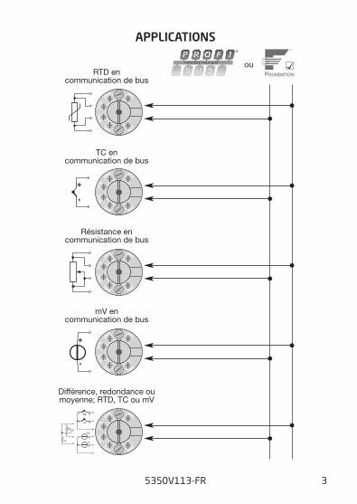
RTD encommunication de bus
Résistance encommunication de bus
mV encommunication de bus
TC encommunication de bus
Différence, redondance oumoyenne; RTD, TC ou mV
ou
APPLICATIONS
5350V113-FR 4
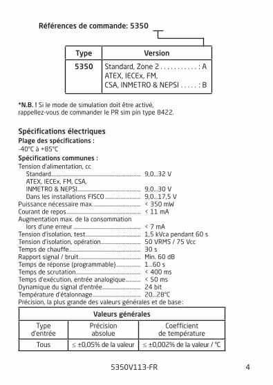
*N.B. ! Si le mode de simulation doit être activé, rappellez-vous de commander le PR sim pin type 8422.
Spécifications électriquesPlage des spécifications :-40°C à +85°C Spécifications communes :Tension d’alimentation, cc Standard ................................................................. 9,0...32 V ATEX, IECEx, FM, CSA, INMETRO & NEPSI .............................................. 9,0...30 V Dans les installations FISCO .......................... 9,0...17,5 V Puissance nécessaire max. .................................. < 350 mW Courant de repos ...................................................... < 11 mA Augmentation max. de la consommation lors d’une erreur ................................................. < 7 mA Tension d’isolation, test ........................................ 1,5 kVca pendant 60 s Tension d’isolation, opération ............................. 50 VRMS / 75 Vcc Temps de chauffe .................................................... 30 s Rapport signal / bruit ............................................. Min. 60 dB Temps de réponse (programmable) .................. 1...60 s Temps de scrutation ............................................... < 400 ms Temps d’exécution, entrée analogique ........... < 50 ms Dynamique du signal d’entrée ............................ 24 bit Température d’étalonnage ................................... 20...28°C Précision, la plus grande des valeurs générales et de base :
Valeurs générales
Type d’entrée
Précision absolue
Coefficient de température
Tous ≤ ±0,05% de la valeur ≤ ±0,002% de la valeur / °C
Références de commande: 5350
Type Version
5350 Standard, Zone 2 . . . . . . . . . . . : AATEX, IECEx, FM, CSA, INMETRO & NEPSI . . . . . : B

5350V113-FR 5
Vibration ...................................................................... IEC 60068-2-6 : 2007 2...25 Hz ................................................................. ±1,6 mm 25...100 Hz ........................................................... ±4 gHumidité ...................................................................... < 95% RH (sans cond.) Dimensions ................................................................. Ø 44 x 20,2 mm Degré de protection (boîtier / bornier) ............ IP68 / IP00 Poids ............................................................................. 55 g
Spécifications électriques, entrée :Entrée résistance linéaire et RTD :
Résistance de ligne par fil ................................... 50 Ω Courant de sonde ..................................................... Nom. 0,2 mA
Valeurs de base
Type d’entrée
Précision de base
Coefficient de température
Pt100 et Pt1000 ≤ ±0,1°C ≤ ±0,002°C / °C
Ni100 ≤ ±0,15°C ≤ ±0,002°C / °C
Cu10 ≤ ±1,3°C ≤ ±0,02°C / °C
R. lin. ≤ ±0,05 Ω ≤ ±0,002 Ω / °C
Volt ≤ ±10 µV ≤ ±0,2 µV / °C
Type TC : E, J, K, L, N, T, U
≤ ±0,5°C
≤ ±0,010°C / °C
Type TC : B, R, S, W3, W5
≤ ±1°C
≤ ±0,025°C / °C
Immunité CEM ............................................................... < ±0,1% d. la valeurImmunité CEM améliorée :NAMUR NE 21, critère A, burst .............................. < ±1% de la valeur
Type RTD
Valeur min.
Valeur max.
Standard
Pt25...Pt1000 Ni25...Ni1000 Cu10...Cu1000 Résistance lin. Potentiomètre
-200°C -60°C -50°C 0 Ω 0 Ω
+850°C +250°C +200°C 10 kΩ
100 kΩ
IEC60751/JIS C 1604 DIN 43760
α = 0,00427 - -
5350V113-FR 6
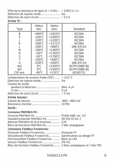
Effet de la résistance de ligne (3- / 4-fils) .... < 0,002 Ω / Ω Détection de rupture sonde ................................ Oui Détection de court-circuit .................................... < 15 ΩEntrée TC :
Compensation de soudure froide (CSF) .......... < ±0,5 °C Détection de rupture sonde ................................ Oui Courant de sonde: pendant la détection ........................................ Nom. 4 μA si non....................................................................... 0 μA Détection de court-circuit .................................... < 3 mVEntrée tension :Gamme de mesure ................................................... -800...+800 mV Résistance d’entrée ................................................ 10 MΩSortie :Connexion PROFIBUS PA :Protocole PROFIBUS PA ............................................ Profile A&B, ver. 3.0 Standard protocole PROFIBUS PA ....................... EN 50170 vol. 2 Adresse PROFIBUS PA (à la livraison) ............... 126 Blocs de fonctions PROFIBUS PA ........................ 2 bloc analogiquesConnexion Fieldbus FOUNDATION :Protocole Fieldbus FOUNDATION ........................... Protocole FF Std protocole Fieldbus FOUNDATION ................... Spécifications au design FF Fonctionnalités Fieldbus FOUNDATION .............. Basic ou LAS Version Fieldbus FOUNDATION .............................. ITK 4.6 Blocs de fonctions Fieldbus FOUNDATION ........... 2 blocs analogiques et 1 bloc PID
Type
Valeur min.
Valeur max.
Standard
B E J K L N R S T U
W3 W5
CSF ext.
+400°C -100°C -100°C -180°C -200°C -180°C -50°C -50°C
-200°C -200°C
0°C 0°C
-40°C
+1820°C +1000°C +1200°C +1372°C +900°C
+1300°C +1760°C +1760°C +400°C +600°C
+2300°C +2300°C +135°C
IEC584 IEC584 IEC584 IEC584
DIN 43710 IEC584 IEC584 IEC584 IEC584
DIN 43710 ASTM E988-90 ASTM E988-90
IEC60751
5350V113-FR 7
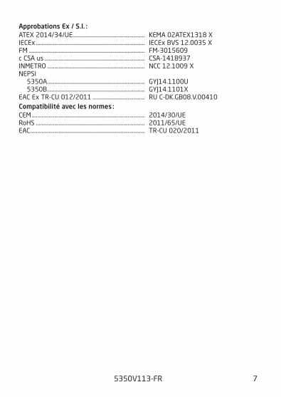
Approbations Ex / S.I. :ATEX 2014/34/UE ................................................... KEMA 02ATEX1318 XIECEx ............................................................................. IECEx BVS 12.0035 XFM .................................................................................. FM-3015609c CSA us ....................................................................... CSA-1418937INMETRO ..................................................................... NCC 12.1009 XNEPSI 5350A ..................................................................... GYJ14.1100U 5350B ..................................................................... GYJ14.1101XEAC Ex TR-CU 012/2011 ..................................... RU C-DK.GB08.V.00410Compatibilité avec les normes :CEM ................................................................................ 2014/30/UERoHS ............................................................................. 2011/65/UEEAC ................................................................................. TR-CU 020/2011
5350V113-FR 8
54 633 4 65
3 4 65
54 63
+-
54 63
54 63
+-
54 63
+-
+-
12
3 4 65 3 4 65 3 4 65
54 63
1
2
54 63
+-
54 6354 63
+-
+-1
2+-
54 63
54 63
1
2
3 4 65
3 4 65
12
+-+-
12
3 4 65
S1
S2
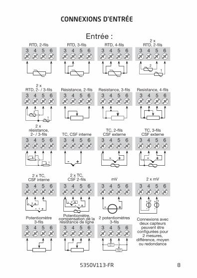
TC, CSF interne
Resistance, 4-�ls
TC, 2-�lsCSF externe
2 x mV
2 x résistance,2- / 3-�ls
2 xRTD, 2- / 3-�ls
TC, 3-�lsCSF externe
2 x TC,CSF 2-�ls
Potentiomètre,compensation de larésistance de ligne
2 potentiomètres3-�ls
2 x TC,CSF interne mV
2 xRTD, 2-�ls
Entrée :
Résistance, 2-�ls
Potentiomètre3-�ls
Resistance, 3-�ls
RTD, 2-�ls RTD, 3-�ls RTD, 4-�ls
Connexions avecdeux capteurspeuvent être
con�gurées pour2 mesures,
différence, moyenou redondance
CONNEXIONS D’ENTRÉE
5350V113-FR 9
1 2
1 2PA
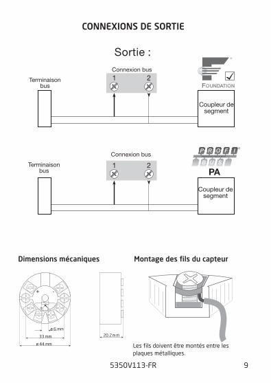
Sortie :Connexion bus
Connexion bus
Coupleur desegment
Coupleur desegment
Terminaisonbus
Terminaisonbus
20.2 mm
+ -
+ -
ø 6 mm
33 mm
ø 44 mm
Dimensions mécaniques Montage des fils du capteur
CONNEXIONS DE SORTIE
Les fils doivent être montés entre les plaques métalliques.
5350V113-FR 10
156 4 3
2
5350
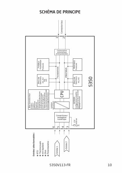
CPU
PR
OF
IBU
S
FO
UN
DA
TIO
N
Isol
atio
nga
lvan
ique EE
PR
OM
Blo
c tr
ansd
ucte
ur
Blo
cs d
efo
ncti
ons
Pro
toco
le
Pro
toco
le
Convertisseuranalogiquenumérique
Confi
gura
tion
com
plèt
eCo
e�ci
ents
de
corr
ecti
onR
égla
ges d
’usi
ne
Entr
ée 1
Entr
ée 2
Di�
éren
ceM
oyen
neR
edon
danc
eTe
mpé
ratu
re d
es b
orne
sU
nité
s de
tech
nolo
gie
Out
ils d
e di
agno
stic
Tabl
es d
e lin
éari
sati
onLi
néar
isat
ion
poly
nom
iale
Etal
onna
ge d
e pr
oces
s
Blo
cs d
efo
ncti
ons
Fiel
dbus
Foun
dati
on
PR
OFI
BU
SCS
Fin
tern
e
Entr
ée 1
Entr
ées
séle
ctio
nnab
les
:
Entr
ée 2
Conn
exio
n bu
s
RTD
Ther
moc
oupl
em
V b
ipol
aire
Ohm
Pote
ntio
mèt
re
AI1
, AI2
Commutationautomatique
entre protocoles
AI1
, AI2
PID
LAS
SCHÉMA DE PRINCIPE
5350V113-FR 11
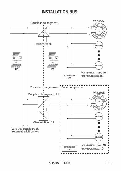
INSTALLATION BUS
PR5350A
PR5350B
1
2
1
2
PR5350A
PR5350A
PR5350B
PR5350B
DP PA
Alimentation
Alimentation, S.I.
Terminaisonbus
Coupleur de segment
FOUNDATION max. 10
PROFIBUS max. 32
Coupleur de segment, S.I.
Zone dangereuseZone non dangereuse
Vers des coupleurs desegment additionnels
PROFIBUS max. 10
FOUNDATION max. 16Terminaison
bus
et et
APPENDIX
ATEX Installation Drawing
FM & CSA Installation Drawing No. 5350QE01
NEPSI Installation Drawing
IECEX Installation Drawing
INMETRO Instruções de Segurança
5350V113-FR 12
ATEX Installation Drawing
5350V113-FR 13
5350QE01 LERBAKKEN 10, 8410 RØNDE DENMARK. WWW.PRELECTRONICS.COM
Page: 1/3
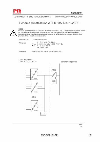
Schéma d’installation ATEX 5350QA01-V3R0
5350B Pour une installation sûre du 5350 vous devez observer ce qui suit. Le module sera seulement installé par un personnel qualifié qui est informé des lois, des directives et des normes nationales et internationales qui s'appliquent à ce secteur. L'année de la fabrication est indiquée dans les deux premiers chiffres dans le numéro de série.
Certificat ATEX KEMA 02ATEX 1318X Marquage
Standards EN 60079-0 : 2012+A11, EN 60079-11 : 2012
Zone non-dangereuse Zone dangereuse Zone 0, 1, 2, 20, 21, 22
II 1 G Ex ia IIC T6...T4 Ga II 2 (1) G Ex ib [ia Ga] IIC T6..T4 Gb II 1 D Ex ia IIIC Da I M 1 Ex ia I Ma
1
2
6
5
4
3
SegmentCoupler
5350BPowerSupply
1
2
6
5
4
35350B
1
2
6
5
4
35350B
Max 10 modules
Termination
1/15
5350V113-FR 14
5350QE01 LERBAKKEN 10, 8410 RØNDE DENMARK. WWW.PRELECTRONICS.COM
Page: 2/3
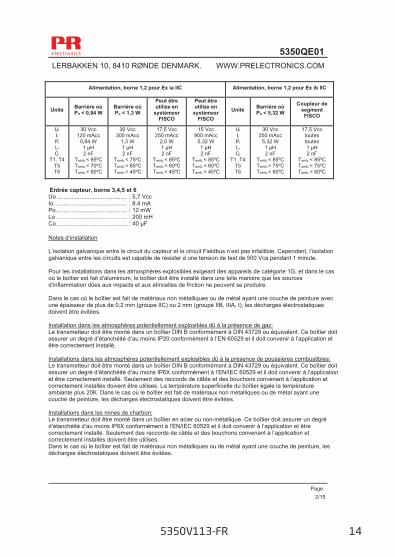
Entrée capteur, borne 3,4,5 et 6
Uo ........................................... : 5,7 Vcc Io ............................................. : 8.4 mA Po ............................................ : 12 mW Lo ............................................ : 200 mH Co............................................ : 40 µF
Notes d‘installation L’isolation galvanique entre le circuit du capteur et le circuit Fieldbus n’est pas infaillible. Cependant, l’isolation galvanique entre les circuits est capable de résister à une tension de test de 500 Vca pendant 1 minute. Pour les installations dans les atmosphères explosibles exigeant des appareils de catégorie 1G, et dans le cas où le boîtier est fait d’aluminium, le boîtier doit être installé dans une telle manière que les sources d’inflammation dûes aux impacts et aux étincelles de friction ne peuvent se produire. Dans le cas où le boîtier est fait de matériaux non métalliques ou de métal ayant une couche de peinture avec une épaisseur de plus de 0,2 mm (groupe IIC) ou 2 mm (groupe IIB, IIIA, I), les décharges électrostatiques doivent être évitées.
Installation dans les atmosphères potentiellement explosibles dû à la présence de gaz: Le transmetteur doit être monté dans un boîtier DIN B conformément à DIN 43729 ou équivalent. Ce boîtier doit assurer un degré d’étanchéité d’au moins IP20 conformément à l’EN 60529 et il doit convenir à l’application et être correctement installé. Installations dans les atmosphères potentiellement explosibles dû à la présence de poussières combustibles: Le transmetteur doit être monté dans un boîtier DIN B conformément à DIN 43729 ou équivalent. Ce boîtier doit assurer un degré d’étanchéité d’au moins IP6X conformément à l’EN/IEC 60529 et il doit convenir à l’application et être correctement installé. Seulement des raccords de câble et des bouchons convenant à l’application et correctement installés doivent être utilises. La température superficielle du boîtier égale la température ambiante plus 20K. Dans le cas où le boîtier est fait de matériaux non métalliques ou de métal ayant une couche de peinture, les décharges électrostatiques doivent être évitées. Installations dans les mines de charbon: Le transmetteur doit être monté dans un boîtier en acier ou non-métallique. Ce boîtier doit assurer un degré d’étanchéité d’au moins IP6X conformément à l’EN/IEC 60529 et il doit convenir à l’application et être correctement installé. Seulement des raccords de câble et des bouchons convenant à l’application et correctement installés doivent être utilises. Dans le cas où le boîtier est fait de matériaux non métalliques ou de métal ayant une couche de peinture, les décharges électrostatiques doivent être évitées.
Alimentation, borne 1,2 pour Ex ia IIC Alimentation, borne 1,2 pour Ex ib IIC
Unité Barrière où Po < 0,84 W
Barrière où Po < 1,3 W
Peut être utilize en
systèmesr FISCO
Peut être utilize en
systèmesr FISCO
Unité Barrière où Po < 5,32 W
Coupleur de segment FISCO
Ui Ii Pi Li Ci
T1..T4 T5 T6
30 Vcc 120 mAcc
0,84 W 1 μH 2 nF
Tamb.< 85ºC Tamb.< 70ºC Tamb.< 60ºC
30 Vcc 300 mAcc
1,3 W 1 μH 2 nF
Tamb.< 75ºC Tamb.< 65ºC Tamb.< 45ºC
17,5 Vcc 250 mAcc
2,0 W 1 μH 2 nF
Tamb.< 85ºC Tamb.< 60ºC Tamb.< 45ºC
15 Vcc 900 mAcc
5,32 W 1 μH 2 nF
Tamb.< 85ºC Tamb.< 60ºC Tamb.< 45ºC
Ui Ii Pi Li Ci
T1..T4 T5 T6
30 Vcc 250 mAcc
5,32 W 1 μH 2 nF
Tamb.< 85ºC Tamb.< 75ºC Tamb.< 60ºC
17,5 Vcc toutes toutes 1 μH 2 nF
Tamb.< 85ºC Tamb.< 75ºC Tamb.< 60ºC
2/15

5350V113-FR 15
5350QE01 LERBAKKEN 10, 8410 RØNDE DENMARK. WWW.PRELECTRONICS.COM
Page: 3/3
5350A: Pour une installation sûre vous devez observer ce qui suit. Le module sera seulement installé par un personnel qualifié qui est informé des lois, des directives et des normes nationales et internationales qui s'appliquent à ce secteur. L'année de la fabrication est indiquée dans les deux premiers chiffres dans le numéro de série
Marquage
Standards EN 60079-0 : 2012+A11, EN 60079-11 : 2012, EN 60079-15 : 2010
Notes d‘installation: L’isolation galvanique entre le circuit du capteur et le circuit Fieldbus n’est pas infaillible. Cependant, l’isolation galvanique entre les circuits est capable de résister à une tension de test de 500 Vca pendant 1 minute. Dans le cas où le boîtier est fait de matériaux non métalliques ou de métal ayant une couche de peinture avec une épaisseur de plus de 0,2mm (groupe IIC) ou 2mm (groupe IIB, IIA), les décharges électrostatiques doivent être évitées. Pour une température ambiante ≥60°C, il faut utiliser des câbles résistant aux températures élevées avec une capacité nominale d’au moins 20 K au-dessus de la température ambiante. Installation dans les atmosphères potentiellement explosibles dû à la présence de gaz: Pour le type d’installation Ex ic, le transmetteur doit être installé dans un boîtier de protection assurant un degré d’étanchéité d’au moins IP20 conformément à l’EN/IEC 60529 60529 et il doit convenir à l’application et être correctement installé. Pour le type d’installation Ex nA, le transmetteur doit être installé dans un boîtier de protection assurant un degré d’étanchéité d’au moins IP54, conformément à l’EN/IEC 50529 et il doit convenir à l’application et être correctement installé, px. un boîtier de type de protection Ex n ou Ex e. Les raccords de câble et les bouchons doivent satisfaire aux mêmes exigences. Installations dans les atmosphères potentiellement explosibles dû à la présence de poussières combustibles: Pour le type d’installation Ex ic où le transmetteur a une interface avec un signal de sécurité intrinsèque du type "ic" (p.ex. un appareil passif), le transmetteur doit être monté dans un boîtier métallique DIN B ou équivalent assurant un degré d’étanchéité d’au moins IP6X conformément à l’EN/IEC 60529 et convenant à l’application. Les raccords de câble et les bouchons doivent satisfaire aux mêmes exigences. Pour une installation sans sécurité intrinsèque le transmetteur doit être monté dans un boîtier assurant un degré d’étanchéité d’au moins IP6X conformément à l’EN/IEC 60529, et conformément au type de protection Ex t. Ce boîtier doit convenir à l’application et être correctement installé. Les raccords de câble et les bouchons doivent satisfaire aux mêmes exigences. Dans le cas où le boîtier est fait de matériaux non métalliques ou de métal ayant une couche de peinture, les décharges électrostatiques doivent être évitées. La température superficielle du boîtier égale la température ambiante plus 20K.
T4: -40 ≤ Ta ≤ 85ºC T5: -40 ≤ Ta ≤ 75ºC T6: -40 ≤ Ta ≤ 60ºC
II 3 G Ex nA [ic] IIC T6..T4 Gc II 3 G Ex ic IIC T6..T4 Gc II 3 D Ex ic IIIC Dc
Borne: 3,4,5,6 Uo: 5,7 V Io: 8,4 mA Po: 12 mW Lo: 200 mH Co: 40 μF
Borne: 1,2 Ex nA U ≤ 32 Vcc
Borne: 1,2 Ex ic Ui = 32 Vcc Li = 1 μH Ci = 2,0 nF
Borne: 1,2 FISCO Ui = 17,5 Vcc Li = 1 μH Ci = 2,0 nF
3/15
FM / CSA Installation Drawing
5350QE01 LERBAKKEN 10, 8410 RØNDE DENMARK. WWW.PRELECTRONICS.COM
Revision date:
2015-10-27 Version /Revision
V4/R0 5350QFC01
V2R0 Page:
4/15
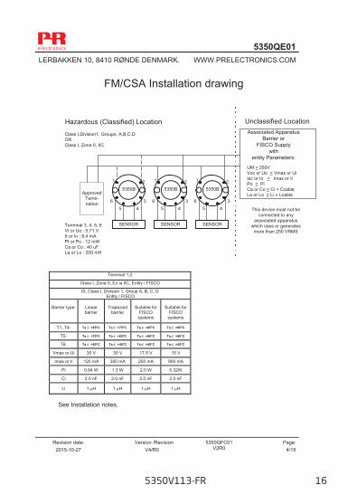
FM/CSA Installation drawing
See Installation notes.
Terminal 1,2
Class I, Zone 0, Ex ia IIC, Entity / FISCO
IS, Class I, Division 1, Group A, B, C, D Entity / FISCO
Barrier type:
Linear barrier
Trapezoid
barrier
Suitable for
FISCO systems
Suitable for
FISCO systems
T1..T4: Ta +85C Ta +75C Ta +85C Ta +85C
T5: Ta +70C Ta +65C Ta +60C Ta +60C
T6: Ta +60C Ta +45C Ta +45C Ta +45C
Vmax or Ui 30 V 30 V 17.5 V 15 V
Imax or Ii 120 mA 300 mA 250 mA 900 mA
Pi 0.84 W 1.3 W 2.0 W 5.32W
Ci 2.0 nF 2.0 nF 2.0 nF 2.0 nF
Li 1 H 1 H 1 H 1 H
Unclassified LocationHazardous (Classified) LocationClass I,Division1, Groups, A,B,C,DORClass I, Zone 0, IIC
Associated ApparatusBarrier or
FISCO Supplywith
entity Parameters:
ApprovedTermi-nation
SENSOR
5350B
1 2
345
6
SENSOR
5350B
1 2
345
6
SENSOR
5350B
1 2
345
6
Terminal 3, 4, 5, 6Vt or Uo : 5,71 VIt or Io : 8,4 mAPt or Po : 12 mWCa or Co : 40 uFLa or Lo : 200 mH
UM < 250VVoc or Uo < Vmax or UiIsc or Io < Imax or IiPo < PiCa or Co > Ci + CcableLa or Lo > Li + Lcable
This device must not beconnected to any
associated apparatuswhich uses or generates
more than 250 VRMS
5350V113-FR 16
5350QE01 LERBAKKEN 10, 8410 RØNDE DENMARK. WWW.PRELECTRONICS.COM
Revision date:
2015-10-27 Version /Revision
V4/R0 5350QFC01
V2R0 Page:
5/15
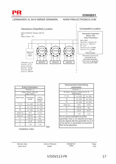
See
Installation notes.
Nonincendive Field Wiring parameters
Terminal 1, 2 NI, Class I, Division 2, Group A, B, C, D
NIFW/ FNICO T1..T4: Ta +85C Ta +85C
T5: Ta +75C Ta +75C
T6: Ta +60C Ta +60C
Vmax / Ui 30 V 17.5 V
Pi 5.32 W any
Ci 2.0 nF 2.0 nF
Li 1 H 1 H
For a current-controlled circuit the parameter Imax is not required and need not be aligned with the parameter Isc or It of the barrier or associated nonincendive field wiring apparatus.
Entity Parameters Terminal 1, 2
Class I, Zone 1, Ex ib IIC Entity / FISCO
Barrier type:
Rectangular
barrier
FISCO
Segment coupler
T1..T4: Ta +85C Ta +85C
T5: Ta +75C Ta +75C
T6: Ta +60C Ta +60C
Vmax / Ui 30 V 17.5 V
Imax or Ii 250 mA any
Pi 5.32 W any
Ci 2.0 nF 2.0 nF
Li 1 H 1 H
Unclassified LocationHazardous (Classified) LocationClass I,Division2, Groups, A,B,C,DORClass I, Zone 1, IIC
Associated ApparatusBarrier with
entity Parameters:
ApprovedTermi-nation
SENSOR
5350B
1 2
345
6
SENSOR
5350B
1 2
345
6
SENSOR
5350B
1 2
345
6
Terminal 3, 4, 5, 6Vt or Uo : 5,71 VIt or Io : 8,4 mAPt or Po : 12 mWCa or Co : 40 uFLa or Lo : 200 mH
UM < 250VVoc or Uo < Vmax or UiIsc or Io < Imax or IiPo < PiCa or Co > Ci + CcableLa or Lo > Li + Lcable
orFISCO Supply
This device must not beconnected to any
associated apparatuswhich uses or generates
more than 250 VRMS
5350V113-FR 17
5350QE01 LERBAKKEN 10, 8410 RØNDE DENMARK. WWW.PRELECTRONICS.COM
Revision date:
2015-10-27 Version /Revision
V4/R0 5350QFC01
V2R0 Page:
6/15
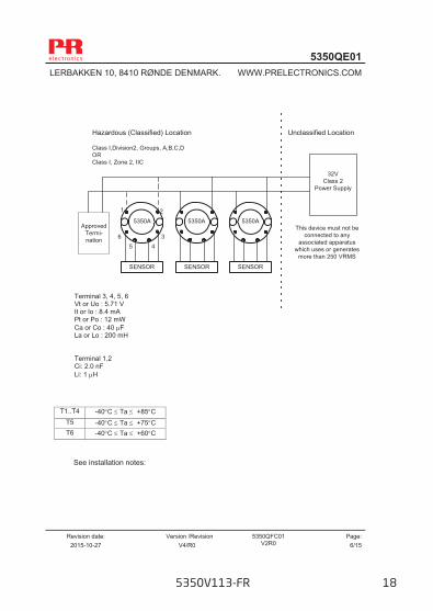
SENSOR
32VClass 2
Power Supply
Unclassified LocationHazardous (Classified) Location
5350A
1 2
345
6
Class I,Division2, Groups, A,B,C,DORClass I, Zone 2, IIC
SENSOR
ApprovedTermi-nation
SENSOR
5350A 5350AThis device must not be
connected to anyassociated apparatus
which uses or generatesmore than 250 VRMS
See installation notes:
T1..T4 -40C Ta +85C T5 -40C Ta +75C
T6 -40C Ta +60C
Terminal 3, 4, 5, 6 Vt or Uo : 5.71 V It or Io : 8.4 mA Pt or Po : 12 mW Ca or Co : 40 F La or Lo : 200 mH Terminal 1.2 Ci: 2.0 nF Li: 1 H
5350V113-FR 18
5350QE01 LERBAKKEN 10, 8410 RØNDE DENMARK. WWW.PRELECTRONICS.COM
Revision date:
2015-10-27 Version /Revision
V4/R0 5350QFC01
V2R0 Page:
7/15
Installation notes: FM / CSA: For installation in the US the 5350 shall be installed according to the National Electrical Code (ANSI-NFPA 70). For installation in Canada the transmitter shall be installed in a suitable enclosure to meet installation codes stipulated in the Canadian Electrical Code (CEC).
The entity concept:
Equipment that is FM / CSA-approved for intrinsic safety may be connected to barriers based on the ENTITY CONCEPT. This concept permits interconnection of approved transmitters, meters and other devices in combinations which have not been specifically examined by FM / CSA, provided that the agency's criteria are met. The combination is intrinsically safe, if the entity concept is acceptable to the authority having jurisdiction over the installation.
The entity concept criteria are as follows: The intrinsically safe devices, other than barriers, must not be a source of power. The maximum voltage Ui (VMAX) and current Ii (IMAX), and maximum power Pi (Pmax),
which the device can receive and remain intrinsically safe, must be equal to or greater than the voltage (Uo or VOC or Vt) and current (Io or ISC or It) and the power Po which can be delivered by the barrier.
The sum of the maximum unprotected capacitance (Ci) for each intrinsically device and the interconnecting wiring must be less than the capacitance (Ca) which can be safely connected to the barrier.
The sum of the maximum unprotected inductance (Li) for each intrinsically device and the interconnecting wiring must be less than the inductance (La) which can be safely connected to the barrier. The entity parameters Uo,VOC or Vt and Io,ISC or It, and Ca and La for barriers are provided by the barrier manufacturer. FISCO/FNICO rules: The FISCO Concept allows the interconnection of intrinsically safe apparatus to associated apparatus not specifically examined in such combination. The criterion for such interconnection is that the voltage (Vmax), the current (Imax) and the power (Pi) which intrinsically safe apparatus can receive and remain intrinsically safe, considering faults, must be equal or greater than the voltage (Uo, Voc, Vt), the current (Io, Isc, It,) and the power (Po) which can be provided by the associated apparatus (supply unit). In addition, the maximum unprotected residual capacitance (Ci) and inductance (Li) of each apparatus (other than the terminators) connected to the Fieldbus must be less than or equal to: FISCO: 5 nF and 10 H. FNICO: 5 nF and 20 H
5350V113-FR 19
5350QE01 LERBAKKEN 10, 8410 RØNDE DENMARK. WWW.PRELECTRONICS.COM
Revision date:
2015-10-27 Version /Revision
V4/R0 5350QFC01
V2R0 Page:
8/15
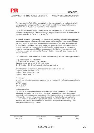
The Nonincendive Field Wiring concept allows the interconnection of nonincendive field wiring apparatus using any of the wiring methods permitted for unclassified locations. Vmax >= Voc or Vt, Ca >= Ci +Ccable, La >= Li + Lcable" The Nonincendive Field Wiring concept allows the interconnection of FM-approved nonincendive devices with FNICO parameters not specifically examined in combination as a system when: Uo or Voc or Vt <= Vmax, Po <= Pi In each I.S. Fieldbus segment only one active source, normally the associated apparatus, is allowed to provide the necessary power for the Fieldbus system. The allowed voltage (Uo, Voc, Vt) of the associated apparatus used to supply the bus must be limited to the range of 14V d.c. to 24V d.c. All other equipment connected to the bus cable has to be passive, meaning that the apparatus is not allowed to provide energy to the system, except to a leakage current of 50 A for each connected device. Separately powered equipment needs a galvanic isolation to insure that the intrinsically safe Fieldbus circuit remains passive. The cable used to interconnect the devices needs to comply with the following parameters: Loop resistance R': 15 ...150 /Km Inductance per unit length L': 0.4…1mH/km Capacitance per unit length C': 80 ...200 nF/km C' = C' line/line + 0.5 C' line/screen, if both lines are floating or C'= C' line/line + C' line/screen, if the screen is connected to one line Length of spur Cable: max. 30 m Length of trunk cable: max. 1 Km Length of splice: max. 1 m Terminators At each end of the trunk cable an approved line terminator with the following parameters is suitable: R = 90 ...100 C = 0 ...2.2 F. System evaluation The number of passive devices like transmitters, actuators, connected to a single bus segment is not limited due to I.S. or N.I. reasons. Furthermore, if the above rules are respected, the inductance and capacitance of the cable need not to be considered and will not impair the intrinsic safety or nonincendive safety of the installation as applicable. The sensor circuit is not infallibly galvanically isolated from the Fieldbus input circuit. However, the galvanic isolation between the circuits is capable of withstanding a test voltage of 500 Vac during 1 minute.
5350V113-FR 20
5350QE01 LERBAKKEN 10, 8410 RØNDE DENMARK. WWW.PRELECTRONICS.COM
Revision date:
2015-10-27 Version /Revision
V4/R0 5350QFC01
V2R0 Page:
9/15
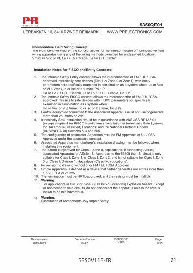
Nonincendive Field Wiring Concept: The Nonincendive Field Wiring concept allows for the interconnection of nonincendive field wiring apparatus using any of the wiring methods permitted for unclassified locations. Vmax >= Voc or Vt, Ca >= Ci +Ccable, La >= Li + Lcable" Installation Notes For FISCO and Entity Concepts: 1. The Intrinsic Safety Entity concept allows the interconnection of FM / UL / CSA-
approved intrinsically safe devices (Div. 1 or Zone 0 or Zone1), with entity parameters not specifically examined in combination as a system when: Uo or Voc or Vt Vmax, Io or Isc or It Imax, Po Pi. Ca or Co Ci + Ccable, La or Lo Li + Lcable, Po Pi.
2. The Intrinsic Safety FISCO concept allows the interconnection of FM / UL / CSA-approved intrinsically safe devices with FISCO parameters not specifically examined in combination as a system when: Uo or Voc or Vt Vmax, Io or Isc or It Imax, Po Pi.
3. Control equipment connected to the Associated Apparatus must not use or generate more than 250 Vrms or Vdc.
4. Intrinsically Safe Installation should be in accordance with ANSI/ISA RP12.6.01 (except chapter 5 for FISCO Installations) “Installation of Intrinsically Safe Systems for Hazardous (Classified) Locations” and the National Electrical Code® (ANSI/NFPA 70) Sections 504 and 505.
5. The configuration of associated Apparatus must be FM Approvals or UL / CSA Approved under the associated concept.
6. Associated Apparatus manufacturer’s installation drawing must be followed when installing this equipment.
7. The 5350B is approved for Class I, Zone 0, applications. If connecting AEx[ib] associated Apparatus or AEx ib I.S. Apparatus to the 5350B the I.S. circuit is only suitable for Class I, Zone 1, or Class I, Zone 2, and is not suitable for Class I, Zone 0 or Class I, Division 1, Hazardous (Classified) Locations".
8. No revision to drawing without prior FM / UL / CSA Approval. 9. Simple Apparatus is defined as a device that neither generates nor stores more than
1.5 V, 0.1 A or 25 mW. 10. The termination must be NRTL-approved, and the resistor must be infallible. 11. Warning:
For applications in Div. 2 or Zone 2 (Classified Locations) Explosion hazard: Except for nonincendive field circuits, do not disconnect the apparatus unless the area is known to be non hazardous.
12. Warning: Substitution of Components May Impair Safety.
5350V113-FR 21
5350QE01 LERBAKKEN 10, 8410 RØNDE DENMARK. WWW.PRELECTRONICS.COM
Revision date:
2015-10-27 Version /Revision
V4/R0 5350QFC01
V2R0 Page: 10/15
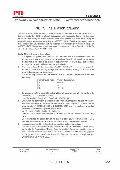
NEPSI Installation drawing Transmitter with Bus technology of Series 5350A manufactured by PR electronics A/S via the test made by NEPSI (National Supervision and Inspection Center for Explosion Protection and Safety of Instrumentation have been proved that they are fulfilling the General Requirements according to Article I, GB3836.1-2010 “Electrical equipement using in the Explosive gas Environment” and the specified requirements for “n” series in Article IX, GB3836.8-2003. The symbol of explosive protection applied should be Ex nA(L) II C T4~T6 while the Certificate No. is GYJ14.1100U. Firstly, Note for the use of the products 1. The Symbol U applied after the Cert. No., indicates that this transmitter cannot be
applied in explosive environment of danget until the Protection Grade of the box where the transmitter will later on be placed is not lower than IP54 (GB4208), and has been approved by the National Authorized Inspection Body.
2. The rated Voltage for the transmitter should be 32Vd.c. Proper measures should be applied to protect the working voltage from instantaneously jumping up to 40% of the rated Voltage caused by disturbance.
3. The relationship between the temperature Code and ambient temperature is indicated as follows:
4. the parameters of the transmitter output which will be connected with the inputs of the
Sensor (X3, X4, X5, X6) are as follows: Uo=5.7V Io=8.4V Po=12mW Co=40 μ F lO=200 mH 5. Only when the transmitter is combined with other power-restraint devices which have
also been tested and approved by the National Authorized Inspection Body and met the requirements of GB3836.1-2000 and GB3836.8-2000 can the explosion protection system be applied in the explosive environment.
Uo<Ui Io<Ii Po≤Pi Co≤Cc+Ci Lo≥Lc+Li Note: Cc, Lc indicated the parameters of distributed electric capacity of connecting
cable. Ui, Ii, Pi indicted the parameters of the output of other power-restraint devices; Ci, Li
indicated the maximum of the external parameter of the power-restraint devices. 6. Users are not allowed to replace the inner electrical parts with permission. 7. The installation, implementation and maintenance of the transmitter should strictly
conform to the Regulation of “Design Code for electricity Equipment used in explosive and flammable environment” in GB50058-1992 and “installation of Electrical Equipment in Dangerous Environment” the Article 15, Electrical Equipment of explosive gas Environment of GB3836.15-2000.
Temperature Code Ambient Temperature T4 -40~+85 T5 -40~+75 T6 -40~+60
5350V113-FR 22
5350QE01 LERBAKKEN 10, 8410 RØNDE DENMARK. WWW.PRELECTRONICS.COM
Revision date:
2015-10-27 Version /Revision
V4/R0 5350QFC01
V2R0 Page: 11/15
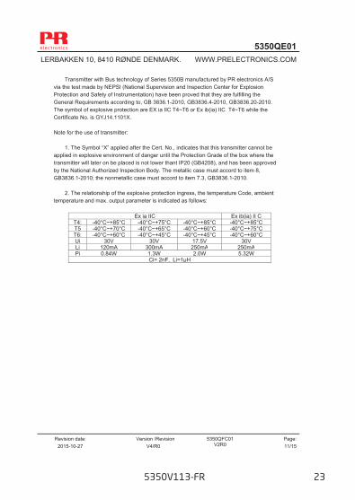
Transmitter with Bus technology of Series 5350B manufactured by PR electronics A/S via the test made by NEPSI (National Supervision and Inspection Center for Explosion Protection and Safety of Instrumentation) have been proved that they are fulfilling the General Requirements according to, GB 3836.1-2010, GB3836.4-2010, GB3836.20-2010. The symbol of explosive protection are EX ia IIC T4~T6 or Ex ib(ia) IIC T4~T6 while the Certificate No. is GYJ14.1101X. Note for the use of transmitter: 1. The Symbol “X” applied after the Cert. No., indicates that this transmitter cannot be applied in explosive environment of danger until the Protection Grade of the box where the transmitter will later on be placed is not lower thant IP20 (GB4208), and has been approved by the National Authorized Inspection Body. The metallic case must accord to item 8, GB3836.1-2010; the nonmetallic case must accord to item 7.3, GB3836.1-2010. 2. The relationship of the explosive protection ingress, the temperature Code, ambient temperature and max. output parameter is indicated as follows:
Ex ia IIC Ex ib(ia) II C T4: -40°C~+85°C -40°C~+75°C -40°C~+85°C -40°C~+85°C T5 -40°C~+70°C -40°C~+65°C -40°C~+60°C -40°C~+75°C T6: -40°C~+60°C -40°C~+45°C -40°C~+45°C -40°C~+60°C Ui 30V 30V 17.5V 30V Li 120mA 300mA 250mA 250mA Pi 0.84W 1.3W 2.0W 5.32W
Ci= 2nF, Li=1µH
5350V113-FR 23
IECEx Installation Drawing
5350QE01 LERBAKKEN 10, 8410 RØNDE DENMARK. WWW.PRELECTRONICS.COM
Revision date:
2015-10-27 Version /Revision
V4/R0 5350QI01
V2R0 Page: 12/15
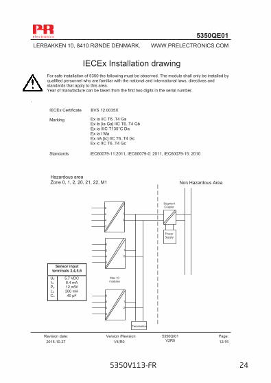
IECEx Installation drawing For safe installation of 5350 the following must be observed. The module shall only be installed by qualified personnel who are familiar with the national and international laws, directives and standards that apply to this area. Year of manufacture can be taken from the first two digits in the serial number.
.
IECEx Certificate BVS 12.0035X Marking
Standards IEC60079-11:2011, IEC60079-0: 2011, IEC60079-15: 2010
Sensor input terminals 3,4,5,6
Uo Io Po Lo Co
5.7 VDC 8.4 mA 12 mW 200 mH 40 µF
Non Hazardous Area Hazardous area Zone 0, 1, 2, 20, 21, 22, M1
Ex ia IIC T6..T4 Ga Ex ib [ia Ga] IIC T6..T4 Gb Ex ia IIIC T135°C Da Ex ia I Ma Ex nA [ic] IIC T6..T4 Gc Ex ic IIC T6..T4 Gc
1
2
6
5
4
3
SegmentCoupler
PowerSupply
1
2
6
5
4
3
1
2
6
5
4
3
Max 10 modules
Termination
5350V113-FR 24

5350QE01 LERBAKKEN 10, 8410 RØNDE DENMARK. WWW.PRELECTRONICS.COM
Revision date:
2015-10-27 Version /Revision
V4/R0 5350QI01
V2R0 Page: 13/15
Installation notes.
The sensor circuit is not infallibly galvanic isolated from the input circuit. However, the galvanic isolation between the circuits is capable of withstanding a test voltage of 500Vac during 1 minute. For an ambient temperature ≥ 60ºC, heat resistant cables shall be used with a rating of at least 20 K above the ambient temperature For installation in a potentially explosive gas atmosphere requiring EPL Ga or EPL Gb, the following instructions apply: The transmitter shall be mounted in an enclosure that is providing a degree of protection of at least IP54 according to IEC 60529 that is suitable for the application and correctly installed.
For installation in a potentially explosive dust atmosphere requiring EPL Da or EPL Db, the following instructions apply: The transmitter shall be mounted in an Form B enclosure according to DIN 43729, that is providing a degree of protection of at least IP6X according to IEC 60079-0 and IEC 60079-31”Equipment dust ignition protection by enclosure tD” that is suitable for the application and correctly installed. Cable entries and blanking elements shall be used that are suitable for the application and correctly installed. Maximum surface temperature with a 5 mm layer of dust is T 135°C. For installation in mines the following instructions apply: The transmitter shall be mounted in a metal enclosure that is providing a degree of protection of at least IP6X according to IEC 60529, and is suitable for the application and correctly installed. Cable entries and blanking elements shall be used that are suitable for the application and correctly installed For installation in a potentially explosive gas atmosphere requiring EPL Gc the following instructions apply: The transmitter shall be mounted in an enclosure according to IEC 60079-15, that is suitable for the application and correctly installed.
Supply, terminal 1,2 Ex ia IIC T6..T4 Ga or Ex ia IIIC Da or Ex ia I Ma
Supply, terminal 1,2 Ex ib [ia Ga] IIC T6..T4 Gb
Unit Barrier where
Po < 0.84 W
Barrier where
Po < 1.3 W
Suitable for FISCO
systems
Suitable for FISCO
systems Unit
Barrier where
Po < 5.32 W
FISCO segment coupler
Ui Ii Pi Li Ci
T1..T4 T5 T6
30 VDC 120 mADC
0.84 W 1 μH 2 nF
Tamb.< 85ºC Tamb.< 70ºC Tamb.< 60ºC
30 VDC 300 mADC
1.3 W 1 μH 2 nF
Tamb.< 75ºC Tamb.< 65ºC Tamb.< 45ºC
17.5 VDC 250 mADC
2.0 W 1 μH 2 nF
Tamb.< 85ºC Tamb.< 60ºC Tamb.< 45ºC
15 VDC 900 mADC
5.32 W 1 μH 2 nF
Tamb.< 85ºC Tamb.< 60ºC Tamb.< 45ºC
Ui Ii Pi Li Ci
T1..T4 T5 T6
30 VDC 250 mADC
5.32 W 1 μH 2 nF
Tamb.< 85ºC Tamb.< 75ºC Tamb.< 60ºC
17.5 VDC any any 1 μH 2 nF
Tamb.< 85ºC Tamb.< 75ºC Tamb.< 60ºC
Supply, terminal 1,2 Ex nA [ic] IIC T6..T4 Gc or Ex ic IIC T6..T4 Gc
Ui Li Ci
T1..T4 T5 T6
Max 32 VDC 1 μH 2 nF
Tamb.< 85ºC Tamb.< 75ºC Tamb.< 60ºC
5350V113-FR 25
5350QE01 LERBAKKEN 10, 8410 RØNDE DENMARK. WWW.PRELECTRONICS.COM
Revision date:
2015-10-27 Version /Revision
V4/R0 Doc. No.
5350QB01 V2R0 Page: 14/15
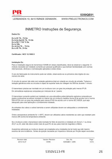
INMETRO Instruções de Segurança.
Dados Ex: Ex ia IIC T6…T4 Ga Ex ib [ia Ga] IIC T6...T4 Gb Ex ia IIIC T 135 °C Da Ex ia I Ma Ex nA [ic] T6 ... T4 Gc Ex ic IIC T6...T4 Gc Certificado:: NCC 12.1009 X Instalação Ex: Para a instalação segura do transmissor 5350B em áreas classificadas, deve-se observar o seguinte: O módulo necessita ser instalado somente por pessoal qualificado e que tenham familiaridade com normas internacionais, diretivas e normalização aplicadas à estas áreas. O ano de fabricação do instrumento pode ser obtido, observando-se os primeiros dois dígitos do seu número de série. O circuito do sensor não está com isolação galvânica total em relação ao circuito de entrada. Todavia a isolação galvânica entre os circuitos é capaz de suportar teste de voltagem de 500Vac durante 1 minuto. O transmissor precisa ser montado em um invólucro com um grau de proteção pelo menos IP-20. Em atmosferas explosivas compostas por misturas de ar / poeira: O transmissor somente poderá ser instalado em uma atmosfera potencialmente explosiva composta por poeira combustível se estiver montado no interior de um invólucro metálico forma B de acordo com a norma DIN 43729 com um grau de proteção pelo menos IP-6X de acordo com a norma IEC 60529, que seja adequado para esta aplicação e corretamente instalado. As entradas dos cabos e outras barreiras a serem utilizadas devem ser adequadas e corretamente instaladas. Onde a temperatura ambiente for ≥ 60ºC, devem ser utilizados cabos resistentes ao calor que resistam pelo menos 20K acima da temperatura ambiente. Se o invólucro onde o transmissor está montado for feito de alumínio e instalado em Zona 0, 1 ou Zona 20,21 ou 22, este não deve conter mais do que 6% do seu peso total de magnésio e titânio. Acessórios adicionais ao invólucro devem ser projetados e/ou instalados de tal modo que até mesmo eventos de rara incidência , fontes de ignição causadas por impactos e faíscas por fricção sejam excluídas.
5350V113-FR 26
5350QE01 LERBAKKEN 10, 8410 RØNDE DENMARK. WWW.PRELECTRONICS.COM
Revision date:
2015-10-27 Version /Revision
V4/R0 Doc. No.
5350QB01 V2R0 Page: 15/15
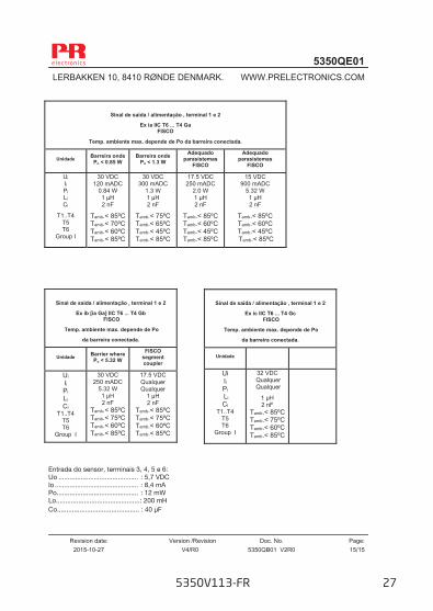
Entrada do sensor, terminais 3, 4, 5 e 6: Uo ........................................... : 5,7 VDC Io ............................................. : 8,4 mA Po ............................................ : 12 mW Lo.............................................: 200 mH Co............................................ : 40 µF
Sinal de saída / alimentação , terminal 1 e 2
Ex ia IIC T6 ... T4 Ga FISCO
Temp. ambiente max. depende de Po da barreira conectada.
Unidade Barreira onde Po < 0.85 W
Barreira onde Po < 1.3 W
Adequado parasistemas
FISCO
Adequado parasistemas
FISCO
Ui Ii Pi Li Ci
T1..T4 T5 T6
Group I
30 VDC 120 mADC
0.84 W 1 μH 2 nF
Tamb.< 85ºC Tamb.< 70ºC Tamb.< 60ºC Tamb.< 85ºC
30 VDC 300 mADC
1.3 W 1 μH 2 nF
Tamb.< 75ºC Tamb.< 65ºC Tamb.< 45ºC Tamb.< 85ºC
17.5 VDC 250 mADC
2.0 W 1 μH 2 nF
Tamb.< 85ºC Tamb.< 60ºC Tamb.< 45ºC Tamb.< 85ºC
15 VDC 900 mADC
5.32 W 1 μH 2 nF
Tamb.< 85ºC Tamb.< 60ºC Tamb.< 45ºC Tamb.< 85ºC
Sinal de saída / alimentação , terminal 1 e 2
Ex ib [ia Ga] IIC T6 ... T4 Gb FISCO
Temp. ambiente max. depende de Po
da barreira conectada.
Unidade Barrier where Po < 5.32 W
FISCO segment coupler
Ui Ii Pi Li Ci
T1..T4 T5 T6
Group I
30 VDC 250 mADC
5.32 W 1 μH 2 nF
Tamb.< 85ºC Tamb.< 75ºC Tamb.< 60ºC Tamb.< 85ºC
17.5 VDC Qualquer Qualquer
1 μH 2 nF
Tamb.< 85ºC Tamb.< 75ºC Tamb.< 60ºC Tamb.< 85ºC
Sinal de saída / alimentação , terminal 1 e 2
Ex ic IIC T6 ... T4 Gc FISCO
Temp. ambiente max. depende de Po
da barreira conectada.
Unidade
Ui Ii Pi Li Ci
T1..T4 T5 T6
Group I
32 VDC Qualquer Qualquer
1 μH 2 nF
Tamb.< 85ºC Tamb.< 75ºC Tamb.< 60ºC Tamb.< 85ºC
5350V113-FR 27
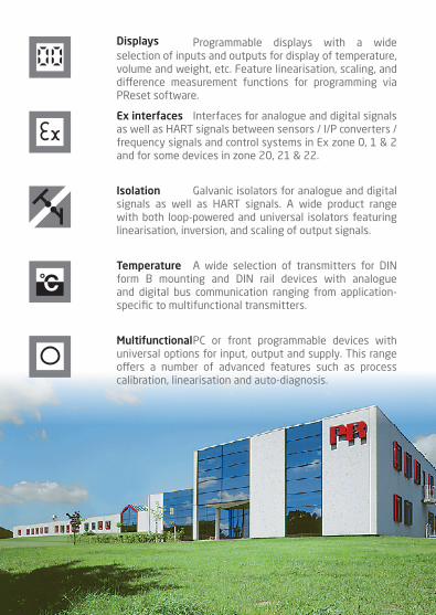
Programmable displays with a wide selection of inputs and outputs for display of temperature, volume and weight, etc. Feature linearisation, scaling, and difference measurement functions for programming via PReset software.
Displays
A wide selection of transmitters for DIN form B mounting and DIN rail devices with analogue and digital bus communication ranging from application- specific to multifunctional transmitters.
Temperature
Galvanic isolators for analogue and digital signals as well as HART signals. A wide product range with both loop-powered and universal isolators featuring linearisation, inversion, and scaling of output signals.
Isolation
Interfaces for analogue and digital signals as well as HART signals between sensors / I/P converters / frequency signals and control systems in Ex zone 0, 1 & 2 and for some devices in zone 20, 21 & 22.
Ex interfaces
PC or front programmable devices with universal options for input, output and supply. This range offers a number of advanced features such as process calibration, linearisation and auto-diagnosis.
Multifunctional

www.prelectronics.fr [email protected]
www.prelectronics.de [email protected]
www.prelectronics.es [email protected]
www.prelectronics.it [email protected]
www.prelectronics.se [email protected]
www.prelectronics.com [email protected]
www.prelectronics.com [email protected]
www.prelectronics.cn [email protected]
www.prelectronics.be [email protected]
Head office
Denmark www.prelectronics.comPR electronics A/S [email protected] 10 tel. +45 86 37 26 77DK-8410 Rønde fax +45 86 37 30 85