Embed Size (px)
Citation preview
A STRUCTURED APPROACH TO COMPUTER GRAPHICS
N. Thalmann* and D. Thalmannt * Section Systemes d'information, Universite Laval tDepartement d'Informatique et de Recherche Operationnelle,
Universite de Montreal
ABSTRACT
139
Graphical programming requires the creation of basic graphical types and a method to construct abstract graphical data types. It is necessary to give the user the means of defining and using specific graphical types. That is the reason why we have designed and implemented a PASCAL extension based on abstract graphical types. The goal of this paper is to show how this extension allows the user to develop applications with a top-down methodology. We show by means of complete examples how it is possible to construct complex figures in the same way as the development of large programs by stepwise refinement. This graphical extension has been designed for computer aided instruction and design and will be applied in various areas, for which we consider that the man-machine communication is important.
UNE APPROCHE STRUCTUREE DU TRAITEMENT GRAPHIQUE PAR ORDINATEUR
La programmation d'applications graphiques exige la creation de types graphiques de base et une methode de construction de types graphiques abstraits. 11 faut fournir a l'uti1isateur les moyens de definir et d'utiliser des types graphiques specifiques. C'est la raison pour 1aque11e nous avons con~u et implante une extension graphique de PASCAL basee sur les types graphiques abstraits. Le but de cet article est de montrer comment cette extension permet de developper des applications avec une methodologie descendante. Nous montrons au moyen d'exemp1es comp1ets comment il est possible de construire des figures complexes de la me me maniere que l'on developpe de grands programmes par raffinements gradue1s. Cette extension graphique a ete creee pour l'enseignement et la conception assistes par ordinateur et sera uti1isee dans des domaines varies, ou nous considerons que la communication homme-machine est importante.
140
A STRUCTURED APPROACH TO COMPUTER GRAPHICS*
Nadia Thalmann Section Syst~mes d'Infonnation Universit~ Laval Qu~bec, Canada
Daniel Thalmann D~partement d'Infonnatique et de Recherche Op~rationnelle Universit~ de Montr~al Montr~al, Canada
1. INTRODUCTION
Since the first ideas on structured programming were established by Dijkstra [1 ] , they have been used time and again and have led to the concepts of systematic programming [2] and program proof [3,4 ]. We can enumerate the major ideas of disciplined programming when we quote three fundamental points which were respectively developed by Dijkstra [5 ] , Hoare [6 1 and Wirth [7 ] .
1) It is proved possible to completely describe a program by means of a decomposition into subactions, which can be sequential or controlled by selection or repetition clauses.
2) A program manipulates data; data organization and structuring must be carefully defined. In a high level programming language, the concept of a data type is very important.
3) A program can be gradually developed in a sequence of refinement steps. In each step, program instructions are decomposed into more detailed instructions.
The actual language which seems to the most adequate to structured progranming techniques is the PASCAL [8,9] language which has been des i gned for thi s purpose [ 10] .
If the development of disciplined programming is necessary, it is also very desirable for the human being to visualize his results; that is the reason why he has tried to develop another aspect of computer science: graphical processing.
With the evolution of technology, very powerful graphical displays have appeared and some graphical languages have been designed [ 11 ,12 ]. The default of these 1 anguages is that there are no graphical types and that good graphic programming requires the creation of
*This research was supported by National Research Council of Canada, Grants A3006 and E4262 and LRSA of Laval University.
141
basic graphical types as well as a method to construct more complicated graphical types. This point is very fundamental, especially when the graphical language is used for design automation, because this design can be made with a top~down approach [ 13 ] .
The goal of this paper is to show the use of graphical types in a well-structured language in order to construct complicated figures with a top-down .methodology.
After having introduced the basic concepts of our graphical PASCAL extension, we will present a complete example to show the construction of a digital network by stepwise refinement.
2. GRAPHICAL TYPES
Why graphical types are required?
A variable of square type must be easily distinct from a variable of circle type. When we write a function to calculate the cubic root of a real number, we find that it is necessary to check if the actual parameter is not a character. The same problem must be solved in graphical processing; writing a procedure to find the intersection point of the diagonals of a quadrilateral has no significance if the actual parameter is a circle. It is necessary to give the user the means of defining and using specific graphical types.
The vector type
The vector type has been introduced and can be used in the same way as the real type. A vector can be given by its two coordinates:
< El,E2 ~ where El and E2 are real expressions.
A vector arithmetic has been developed using vector addition and a scalar product. A vector can be read and written, and caQ be the result of a function.
e.g.
The fi gure type
PROGRAM SIHPLE(INPUT,OUTPUT); ~AR Vi,V2,V3: VECTOR' R:REAL' BEGIN Vi:= «-5.2,4.3» ' V2: = 2*Vi' READ(Vi)' V3:= Vi+V2' R: = Vi*V2; WR ITE (V3, R) END.
Most objects which are familiar to us can be constructed with the help of very Simple figures, characterized by a few parameters. For example, a circle is determined by its radius and its center, a segment by its two vectors, a triangle by three.
142
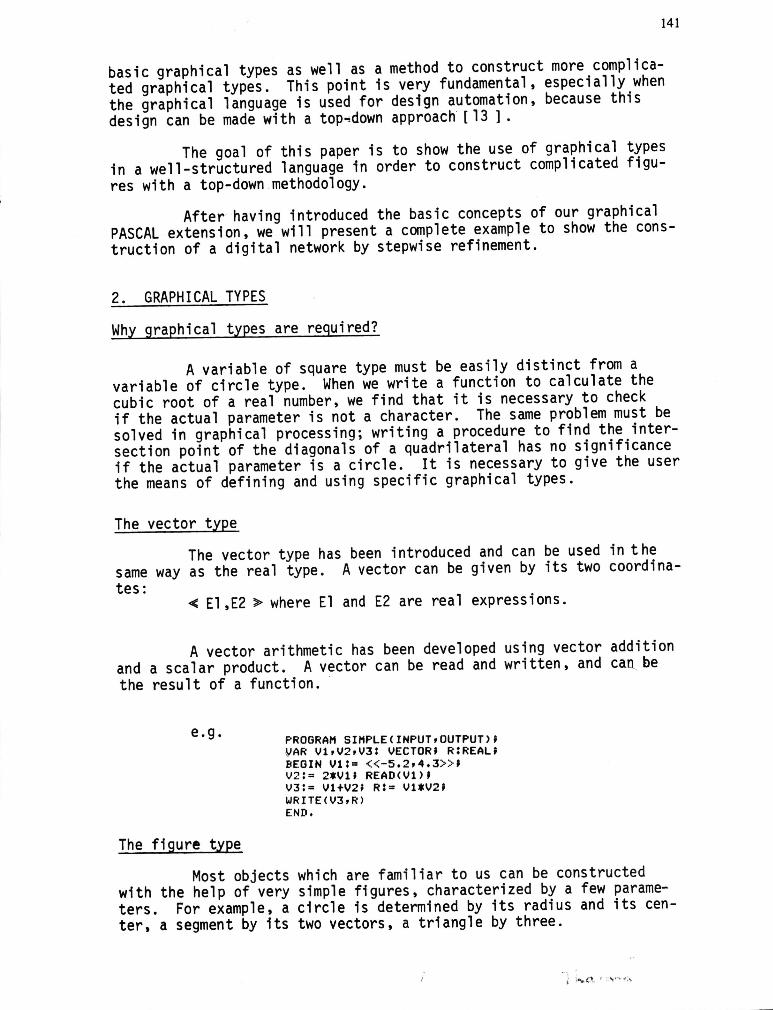
Because of these considerations, it was necessary to use variables of graphical types, characterized by a few parameters. That is the reason why we have introduced a new structured type in PASCAL. the figure type, which is an abstract type. The syntax of such a type is shown in Fig. 1.
type formal parameter section
Fig. 1 Syntactic diagram of the figure type
To define a new figure type, it is necessary to take the following steps:
10 Find the figure characterics, which give the figure para-meters
20 Find the algorithm, which allows one to construct the figure with the help of the parameters.
To facilitate this second step, we have introduced, in our extension, the statement connect (Xl, X2, ... , Xn) which links the vectors Xl, X2, ... Xn.
Let's show two examples:
a) The triangle
10 Its characteristics are its 3 vertices a,b,c 20 The figure can be build by connecting its 3 vertices.
The following program shows how to define the triangle type:
PROGRAM TRYCINPUT,OUTPUT)~
TYPE TRIANGLE = FIGURECA,B,C:VECTOR)~ BEGIN CONNECTCA,B,C) END~
VAR T:TRIANGLE~ X,Y,Z:VECTOR' BEGIN READ(X,Y,Z)' CREATE T(X,Y,Z)/ DRAW T END.
The create statement creates dynamically in memory a new figure; at this time, the real characteristics of the figures are determined. The draw statement permits a created figure to be drawn. The erase statement erases the figure, while the delete statement releases it in the memory.
143
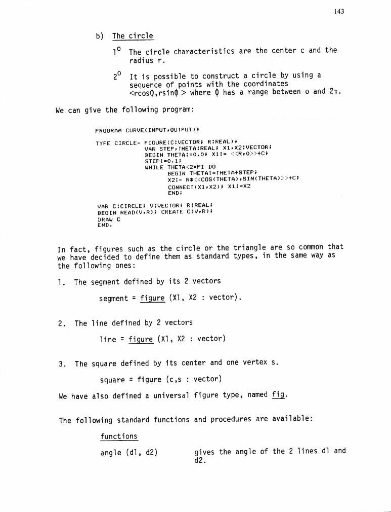
b) The circle
10 The circle characteristics are the center c and the radius r.
20 It is possible to construct a circle by using a sequence of points with the coordinates <rcos~,rsin~ > where ~ has a range between 0 and 2n.
We can give the following program:
PROGRAM CURVE(INPUT,OUTPUT);
TYPE CIRCLE = FIGURE(C:VECTOR; R:REAL); VAR STEP,THETA:REAl; Xl,X2:VECTOR; BEGIN THETA:=O.O; Xl:= « R,O» tC; STEP:=O.U WHILE THETA<2*PI DO
BEGIN THETA:=THETAtSTEP; X2:= R* « COS(THETA),SIN(THETA» >tC; CONNECT(Xl,X2); Xl:=X2 END;
VAR C:CIRCLE; V:VECTOR; R:REAL; BEGIN READ(V,R); CREATE C(V,R); DRAW C END.
In fact, figures such as the circle or the triangle are so common that we have decided to define them as standard types, in the same way as the following ones:
1. The segment defined by its 2 vectors
segment = figure (Xl, X2 : vector).
2. The line defined by 2 vectors
line = figure (Xl,X2: vector)
3. The square defined by its center and one vertex s.
square = figure (c,s : vector)
We have also defined a universal fi gure type, named f.i9..
The following standard functions and procedures are available:
functions
angle (dl, d2) gives the angle of the 2 lines dl and d2.
144
inter (dl, d2) gives the intersection point of the 2 li nes dl and d2.
center (f) gives the center of gravity of the figure f.
dist (vl, v2) gives the distance between the 2 points vl and v2.
projx (v), projy (v) give the coordinates of the point v.
procedures (For the first four procedures, the figure f2 is obtained by a symmetry operation on figure fl).
symmetry (fl, 1, f2) symmetry about the l-axis
translation (fl, t, f2) translation by vector t
rotation (fl, c, alpha, rotation about c by the angle alpha f2)
homothety (fl, c, r, f2)
union (fl, f2, f3)
readgraph (pl, p2, ... , pn)
homothety of center c and ratio r.
construction of figure f3 through the union of the figures fl and f2.
allows to enter figures and/or vectors by graphical input.
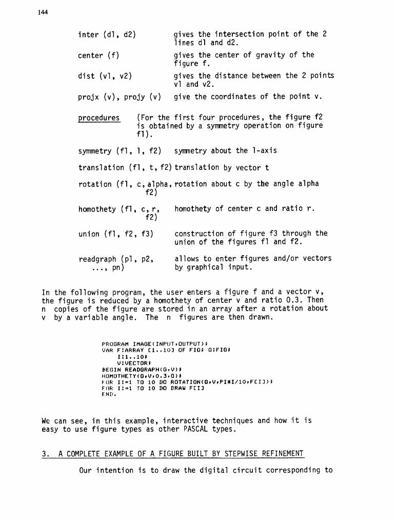
In the following program, the user enters a figure f and a vector v, the figure is reduced by a homothety of center v and ratio 0.3. Then n copies of the figure are stored in an array after a rotation about v by a variable angle. The n figures are then drawn.
PROGRAM IMAGE(INPUT,OUTPUT); VAR F:ARRAY [1 •• 10) OF FIG; G:FIG;
1:1 .. 10' V:VECTOR'
BEGIN READORAPH(O,V) , HOMOTHETY(O,V,0.3,O)' FOR 1:-1 TO 10 DO ROTATIONCO,V,PI*I/10,F[I); FOR l:a1 TO 10 DO DRAW F[I) END.
We can see, in this example, interactive techniques and how it is easy to use figure types as other PASCAL types.
3. A COMPLETE EXAMPLE OF A FIGURE BUILT BY STEPWISE REFINEMENT
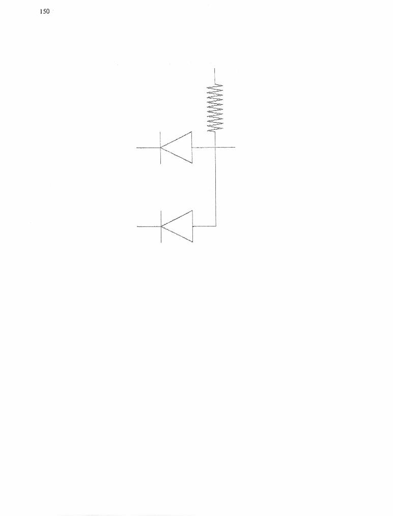
Our intention is to draw the digital circuit corresponding to
145
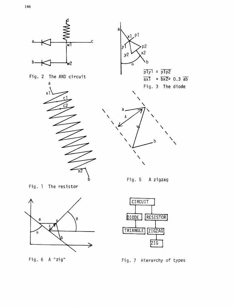
the logical gate and. As we know it, such a circuit is divided into three parts: twodTodes dl and d2 and one resistor r. The circuit has 2 inputs a and b and one output c (see Fig. 2). Moreover, an auxiliary point d is necessary for the connection to voltage power.
CIRCUIT = FIGURE(A,B,C!VECTOR; VAR D:VECTOR);
We have made
1)
2) 3)
VAR Dl,D2!DIODE; R:RESISTOR; Wl,W2!VECTOR; BEGIN Wl:=AtO.8*(C-A); W2!=BtWI-A; D!=2*WI-W2; CREATE Dl(A,Wl); CREATE D2(B,W2); CREATE R(D,Wl); CONNECT(Wl,C); CONNECT(Wl,W2); INCLUDE Dl,D2,R END;
the following geometrical assumptions:
wl is at about 80% of the distance ac a, b, wl and w2 are the 4 vertices of a rectangle. d is the symmetrical of w2 about wl.
The create statement creates 2 diodes and one resistor between the 4 points a, b, c, d. The figure is completely created b~nclud~these three elements (include statement) and the 2 segments wlc and wlw2 . Now, we have to construct a diode (Fig.3) between the 2 points a and b.
The diode type can be defined as:
DIODE= FIGURE(A,B:VECTOR); VAR Xl,X2,Pl,P2,P!VECTOR; ALPHA:REAL; T:TRIANGLE; BEGIN Xl!=AtO.3*(B-A); X2:=AtO.7*(B- A); ALPHA:=ANGLEPROJ(Xl,X2); P!=(DIST(Xl,X2)/2)*« COS(ALPHA),SIN(ALPHA» > ; P2:=X2tP; Pl!=XltP; CONNECT(A,Xl,Pl,2*Xl-Pl); CREATE T(Xl,P2,2*X2-P2); INCLUDE T; CONNECT(X2,B) END;
The function angleproj (a,b) gives the angle between the vertical axis and the 1 i ne ab.
At this point, the resistor (Fig.4) is constructed by stepwise refinement; two segments aX l and x2b are used with a length of 20% of the distance ab and a sequence of ten zigzags which have a width of 1/3 of the distance xl x2.
:, ~ ,:~. .. ,t ~ .. .. ...
146
a
a ,,-_-+-~ ___ IC
b b
plyl = plp2 Fi g. 2 The AND circuit axl = ~= 0.3 ao
a Fig. 3 The diode
"-"-
"-\.
\. \.
\. \.
\. b "-\.
\ \. ,
\.
Fig. 5 A zigzag Fig. 1 The resistor
Fi g. 6 A" zi g" Fig. 7 Hierarchy of types
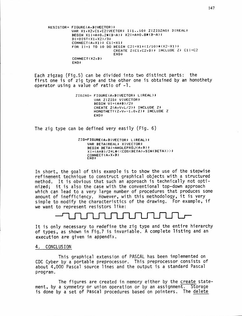
RESISTOR= FIGURE(A,B:VECTOR); VAR Xl,X2,Cl,C2:VECTOR; 1:1 •• 10; Z:ZIGZAG; D:REAL; BEGIN Xl: =AtO.2*(B-A); X2:=AtO.B*(B-A); D:=DIST(Xl,X2)/3J CONNECT(A,Xl); Cl:=Xl; FOR 1:=1 TO 10 DO BEGIN C2: =Xlt(1/10)*(X 2-Xl);
CONNECT(X2,B) END;
CREATE Z(Cl,C2,D); I NCLUDE Z; Cl: =C2 END;
Each zigzag (Fig.5) can be divided into two distinct parts: the
147
first one is of zig type and the other one is obtained by an homothety operator using a value of ratio of -1.
ZIGZAG = FIGURE(A,B:VECTORJ L:REAL); VAR Z:ZIG; V:VECTOR; BEGIN V:~(At8)/2; CREATE Z(A,V,L/2); INCLUDE Z; HOMOTHETY(Z,V,-1.0,Z)' INCLUDE Z END;
The zig type can be defined very easily (Fig. 6)
ZIG=FIGURE(A,B:VECTOR; L:REAL); VAR BETA:REAL; X:VECTOR; BEGIN BETA:=ANGLEPROJ(A,B); X: =(AtB)/2tL*« COS(BETA),SIN(BETA» > ; CONNECT(A,X,B) END;
In short, the goal of this example is to show the use of the stepwise refinement technique to construct graphical objects with a structured method. It is obvious that such an approach is technically not optimized; it is also the case with the conventional top-down approach which can lead to a very large number of procedures that produces some amount of inefficiency. However, with this methodology, it is very simple to modify the characteristics of the drawing. For example, if we want to represent resistors like:
It is only necessary to redefine the zig type and the entire hierarchy of types, as shown in Fig.7 is invariable. A complete listing and an execution are given in appendix.
4. CONCLUSION
This graphical extension of PASCAL has been implemented on COC Cyber by a portable preprocessor. This preprocessor consists of about 4,000 Pascal source lines and the output is a standard Pascal program.
The figures are created in memory either by the create statement, by a symmetry or union operation or by an assignment. Storage is done by a set of Pascal procedures based on pointers. The delete
}48
statement releases memory entirely since an efficient garbage collector has been developed. The include statement corresponds to the operation wherein a pointer is updated; it does not create a copy in memory. The connect statement is processed as chain building.
The graphical devices used are a display HP2648A and a VERSATEC printer. The extension has been designed for computer aided instruction and design and will be applied in various areas, for which we consider that the man-machine communication is important.
5. ACKNOWLEDGEMENT
The authors are grateful to C. Pellegrini who has worked for the pr.eprocessor.
6. REFERENCES
[1] Dijkstra, E.W. "Prograrrming Considered as a Human Activity", Proc. IFIP Congr., 1965, pp. 213-217.
[2] Wirth, N. "Systematic Programming: An Introduction", PrenticeHall,1973.
[3] Naur, P. "Proof of Algorithms by General Snapshots", BIT, 6 (1966), pp. 310-316.
[4] Hantler, S.L. and King, J.C. "An Introduction to Proving the Correctness of Programs ll
, Computing Surveys 8 (1976) 3.
[5] Dijkstra, E.W. IINotes on Structured Programming", N. V., Academic Press, 1972.
[6] Hoare, C.A.R. IINotes on Data Structuring", N.V., Academic Press, 1972.
[7 ] Wirth, N. "Program Development by Stepwise Refinement", Comm. ACM, 14 (1971) 4, pp. 221-227.
[8 ] Jensen, K. and Wirth, N. "Pascal User Manual and Report", Berlin Springer-Verlag, 1975.
[9 ] Hoare, C.A.R. and Wirth, N. "An Axiomatic Definition of the Programming Language PASCAL", Acta Informatica, 2(1973), pp. 335-355.
[101 Thalmann, N. and Thalmann, D. liThe Use of Pascal as a Teaching Tool in Introductory, Intermediate and Advanced Computer Science Courses ll
, Proc. SIGCSE/CSA Techn. Symp., Detroit, 1978, SIGCSE Bulletin, 10 (1978) 1, pp. 277-281.
[11 ] Shapiro, L.G. "ESP3: A High-Level Graphics Language", Proc. Siggraph ' 75, Computer Graphics, 9 (1975) 1, pp. 70-77.
149
[ 12 ] O'Brien, C.D. et Brown, H.G. "IMAGE: a Language for the Interactive Manipulation of a Graphics Environment", Proc. Siggraph ' 75, Computer Graphics, 9 (1975) 1, pp. 53-60.
[ 13 ] Stevens, W.P.; Myers, G.J. and Constantine, L.L. "Structured Design", IBM Systems Journal 13 (1974) 2, pp. 115-139.
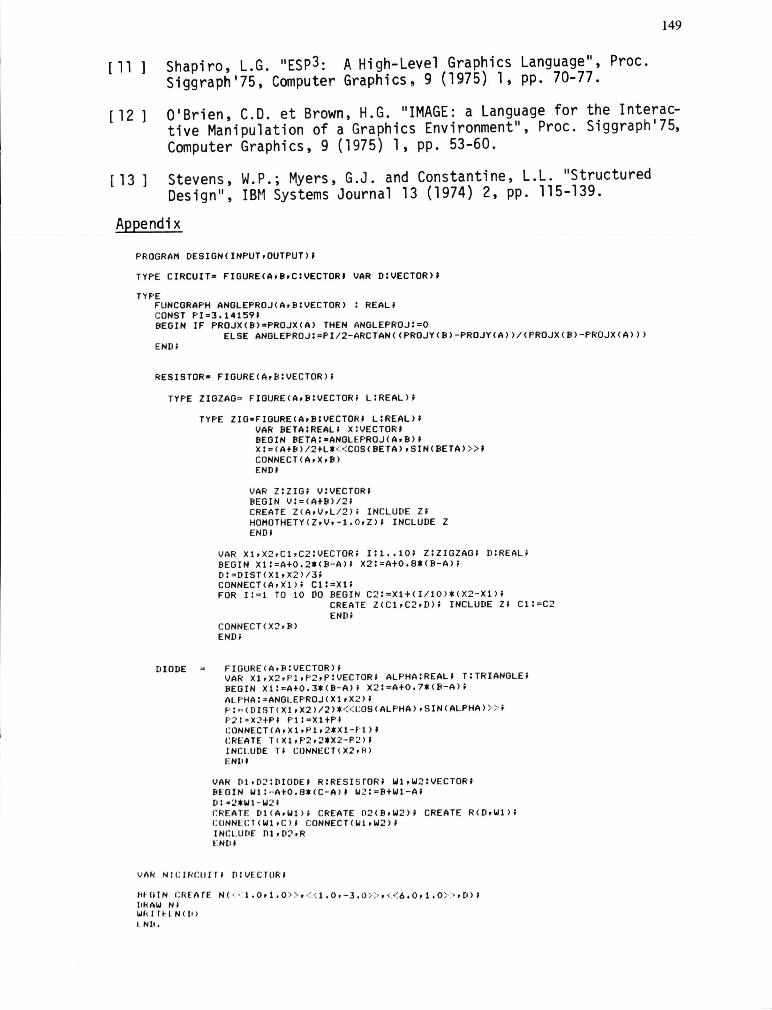
Appendix
PROGRAM DESIGNIINPUT,OUTPUT)'
TYPE CIRCUIT- FIGUREIA,B,C:VECTOR' VAR D:VECTOR)'
TYPE FUNCGRAPH ANGLEPROJIA,B:VECTOR) : REAL; CONST PI=3.14159' BEGIN IF PROJXIB)zPROJXIA) THEN ANGLEPROJ:=O
ELSE ANGLEPROJ:=PI/2-ARCTANIIPROJYIB)-PROJYIA»/IPROJXIB)-PROJXIA») END;
RESISTOR- FIOUREIA,B:VECTOR"
TYPE ZIOZAG = FIOUREIA,B:VECTOR; L:REAL',
DIODE
TYPE ZIO-FIOUREIA,BIVECTOR' L:REAL)I VAR BETAIREALI X:VECTOR' BEOIN BETA:-ANOLEPROJIA,B) , XI=IA+B'/2+L* « COSIBETA),SINIBETA» > 1 CONNECTlA,X,B) END'
VAR Z:ZIG; V:VECTOR; BEGIN V:=IA+B'/2; CREATE ZIA,V,L / 2); INCLUDE Z; HOMOTHETYIZ,V,-1.0,Z); INCLUDE Z ENDI
VAR Xl,X2,Cl,C2:VECTOR; 1:1 •• 10; Z:ZIGZAG; D:REAL; BEGIN Xl:=A+0.2*IB-A); X2:=A+0.8*IB-A); D:=DISTIX1,X2'/3; CONNECTIA,Xl); Cl:=Xl; FOR 1:=1 TO 10 DO BEGIN C2:=Xl+II/10)*IX2-Xl);
CONNECTIX2,B' END;
CREATE ZIC1,C2,D); INCLUDE Z; Cl:=C2
FIGUREIA,B:VECTOR); VAR Xl,X2,PI,P2,P:VECTOR; ALPHA:REAL; T:TRIANGLE; BEGIN Xll=A+0.3*IB-A); X21=A+0.7*IB-A'; ALPHA: - ANGLEPROJIX1,X 2'1 rl - IDISTIX1,X2)/2)* « COSI ALPHA),SINIALPHA» ) ; P21 - X2+P' PI:-Xl+P' CO NNECTIA,XI,Pl, 2*XI-Pl)' CREATE TIXI,P2,2*X2-P21' INCLUDE TI CONNECT(X2.~'
ENO'
VAR 01.02:DIOOE' RIRESIsrORI Wl,W2:VECTOR' BEOIN WI: nA+0.8*IC-AII W21= B+WI - A' DI·2*Wl - W2 ' rRE ATE DIIA,Wl', CREATE D2IB,W2)' CREATE RIO,WI', CU NN ECTI W1.C', CONNECTIW1,W2" INCLUDE 01,D2,R EN["
VAk NI CIRCUIT. DIVECTURI
1.I· urN I:REAr E NI '· · . l,O,1.0 .~· ) ' « l,O, - 3,O» , <:'{ 6.0,1.0» ,DI;
l'RAW NI W/, I r~ I NIL') l Nl"
150


![76 UMLV Types abstraits Types de base entiers, réels, booléens, caractères, pointeurs (adresses),… Constructeurs puissanceE n type_E... […] produit cartésienE](https://img.pdfslide.fr/doc/110x75/551d9db6497959293b8dafe9/76-umlv-types-abstraits-types-de-base-entiers-reels-booleens-caracteres-pointeurs-adresses-constructeurs-puissancee-n-typee-produit-cartesiene.jpg)