Embed Size (px)
Citation preview
i
UNIVERSITE PARIS-SUD
ÉCOLE DOCTORALE : Informatique de Paris-Sud Laboratoire de Recherche en Informatique
DISCIPLINE Informatique
THÈSE DE DOCTORAT
soutenue le 09/07/2013
par
Anh Tuan LY
Accès et utilisation de documents multimédia complexes dans une bibliothèque numérique
Directeur de thèse : Nicolas SPYRATOS Professeur, Universite Paris Sud, France
Composition du jury : Président du jury : Philippe RIGAUX Professeur, CNAM, France Rapporteurs : Dominique LAURENT Professeur, Universite Cergy-Pontoise, France Peter STANCHEV Professeur, Kettering University, USA Examinateurs : Chantal REYNAUD Professeur, Universite Paris Sud, France
Francois GOASDOUE MdC Habilite, Universite Paris Sud, France
ii
Accessing and using complex multimedia
documents in a digital library
A thesis presented
by
Anh Tuan LY
to
the Laboratoire de Recherche en Informatique
in partial fulfillment of the requirements
for the degree of
Doctor of Philosophy
in the subject of
Computer Science
Université Paris-Sud
July 2013
iii
Abstract
In the context of three European projects, our research team has developed a data model and
query language for digital libraries supporting identification, structuring, metadata, and
discovery and reuse of digital resources. The model is inspired by the Web and it is formalized as
a first-order theory, certain models of which correspond to the notion of digital library. In
addition, a full translation of the model to RDF and of the query language to SPARQL has been
proposed to demonstrate the feasibility of the model and its suitability for practical applications.
The choice of RDF is due to the fact that it is a generally accepted representation language in the
context of digital libraries and the Semantic Web.
One of the major aims of the thesis was to design and actually implement a simplified form of a
digital library management system based on the theoretical model. To obtain this, we have
developed a prototype based on RDF and SPARQL, which uses a RDF store to facilitate internal
management of metadata. The prototype allows users to manage and query metadata of digital or
non-digital resources in the system, using URIs as resource identifiers, a set of predicates to
model descriptions of resources, and simple conjunctive queries to discover knowledge in the
system. The prototype is implemented by using Java technologies and the Google Web Toolkit
framework whose system architecture consists of a storage layer, a business logic layer, a service
layer and a user interface. During the thesis work, the prototype was built, tested, and debugged
locally and then deployed on Google App Engine. In the future, it will be expanded to become a
full fledged digital library management system.
Moreover, the thesis also presents our contribution to content generation by reuse. This is mostly
theoretical work whose purpose is to enrich the model and query language by providing an
important community service. The incorporation of this service in the implemented system is left
to future work.
Keywords: Digital Libraries, Conceptual Modeling, First-order Logic, Web Architecture, RDF,
SPARQL, Google Web Toolkit, Prototype, Content Reuse
iv
Résumé:
Dans le cadre de trois projets européens, notre équipe a mis au point un modèle de données et un
langage de requête pour bibliothèques numériques supportant l'identification, la structuration, les
métadonnées, la réutilisation, et la découverte des ressources numériques. Le modèle proposé est
inspiré par le Web et il est formalisé comme une théorie du premier ordre, dont certains modèles
correspondent à la notion de bibliothèque numérique. En outre, une traduction complète du
modèle en RDF et du langage de requêtes en SPARQL a également été proposée pour démontrer
son adéquation à des applications pratiques. Le choix de RDF est dû au fait qu’il est un langage
de représentation généralement accepté dans le cadre des bibliothèques numériques et du Web
sémantique.
L’objectif de cette thèse était double: concevoir et mettre en œuvre une forme simplifiée de
système de gestion de bibliothèques numériques, d’une part, et contribuer à l’enrichissement du
modèle, d’autre part. Pour atteindre cet objectif nous avons développé un prototype d’un système
de bibliothèque numérique utilisant un stockage RDF pour faciliter la gestion interne des
métadonnées. Le prototype permet aux utilisateurs de gérer et d’interroger les métadonnées des
ressources numériques ou non-numériques dans le système en utilisant des URIs pour identifier
les ressources, un ensemble de prédicats pour la description de ressources, et des requêtes
conjonctives simples pour la découverte de connaissances dans le système. Le prototype est mis
en œuvre en utilisant les technologies Java et l’environnement de Google Web Toolkit dont
l'architecture du système se compose d'une couche de stockage, d’une couche de métier
logique, d’une couche de service, et d’une interface utilisateur. Pendant la thèse, le prototype a
été construit, testé et débogué localement, puis déployé sur Google App Engine. Dans l’avenir, il
peut être étendu pour devenir un système complet de gestion de bibliothèques numériques.
Par ailleurs, la thèse présente également notre contribution à la génération de contenu par
réutilisation de ressources. Il s’agit d’un travail théorique dont le but est d’enrichir le modèle en
lui ajoutant un service important, à savoir la possibilité de création de nouvelles ressources à
partir de celles stockées dans le système. L’incorporation de ce service dans le système sera
effectuée ultérieurement.
Mots clés: Bibliothèques numériques, Modélisation conceptuelle, Logique du premier ordre,
Architecture Web, RDF, SPARQL, Google Web Toolkit, Prototypes, Réutilisation de contenu

v
Acknowledgments
I would first of all like to express my deepest gratitude to my supervisor, Professor Nicolas
Spyratos. His suggestions, comments and guidance have helped me through the research process
and finally write this thesis. He has not only encouraged me to pass several critical phases but
has also guided and enabled me to successfully complete this research.
I am grateful to Dr. Tsuyoshi Sugibuchi, who was very helpful in giving me his valuable
suggestions and comments on my research tasks, all of which helped to improve the quality of
my work.
I would like to thank Dr. Nguyen Ngoc Hoa who has shared discussions with me about my
research method, design and analysis while studying and living in Vietnam.
I want to thank my colleagues, Tsuyoshi Sugibuchi, Jitao Yang, Ekaterina Simonenko, Cao
Phuong Thao and Nguyen Huu Nghia with whom I had a pretty good time in the Laboratoire de
Recherche en Informatique.
I want to thank Huynh Khanh Duy for his help at the beginning of my living in France and many
other friends in France for their encouragement, support, and friendship throughout my degree
study in France.
Finally, I thank my wife and children for their love and support through all these years.
vi
Table of contents
Abstract ......................................................................................................................................... iii
Acknowledgments ......................................................................................................................... v
Table of contents .......................................................................................................................... vi
1 Introduction and State of the Art ........................................................................................ 1
1.1 Digital Libraries ............................................................................................................... 1
1.2 Digital Library Systems ................................................................................................... 3
1.3 Digital Library System design and implementation Models ............................................ 6
1.4 Contributions of the Thesis .............................................................................................. 9
1.5 Outline of the Thesis ...................................................................................................... 12
2 A Data Model for Digital Libraries ................................................................................... 14
2.1 Digital Library: An Informal Introduction ..................................................................... 15
2.1.1 Resource .................................................................................................................. 15
2.1.2 The Reference Table of a Digital Library ............................................................... 16
2.1.3 The Metadata Base of a Digital Library ................................................................. 19
2.1.4 An Example ............................................................................................................ 25
2.2 The Definition of a Digital Library ................................................................................ 27
2.3 Capturing Implicit Knowledge ....................................................................................... 30
2.3.1 The Language L ..................................................................................................... 30
2.3.2 The Axioms A......................................................................................................... 31
2.4 Complete Digital Libraries ............................................................................................. 33
vii
2.5 Querying a Digital Library ............................................................................................. 36
2.5.1 The Language L + ................................................................................................... 37
2.5.2 Queries and Answers .............................................................................................. 39
3 Background technologies.................................................................................................... 44
3.1 Asynchronous JavaScript and XML (AJAX)................................................................. 44
3.2 Java Servlet .................................................................................................................... 45
3.3 Resource Description Framework (RDF) ...................................................................... 46
3.3.1 RDF data model ...................................................................................................... 47
3.3.2 Resource Description Framework Schema (RDFS) ............................................... 48
3.4 SPARQL......................................................................................................................... 49
3.5 SPARQL Update ............................................................................................................ 51
3.6 Triplestore ...................................................................................................................... 52
3.7 Jena ................................................................................................................................. 53
3.8 Google Web Toolkit (GWT) .......................................................................................... 54
3.8.1 GWT Components .................................................................................................. 55
3.8.2 Remote Procedure Calls (RPCs) ............................................................................. 55
4 Implementation of the Model based on RDF and SPARQL ........................................... 58
4.1 Implementing the Model ................................................................................................ 58
4.2 Mapping to RDF............................................................................................................. 59
4.2.1 The Function ....................................................................................................... 61
4.2.2 The Function R....................................................................................................... 69
4.2.3 Computational Issues .............................................................................................. 71
viii
4.3 Translation from Q to SPARQL .................................................................................... 71
4.3.1 Translation of Identifiers and Variables ................................................................. 72
4.3.2 The Function ....................................................................................................... 72
4.3.3 Correctness .............................................................................................................. 79
5 The actual implementation of the model .......................................................................... 81
5.1 Functional Specification ................................................................................................. 82
5.1.1 Definitions............................................................................................................... 82
5.1.2 Technical requirements ........................................................................................... 83
5.1.3 The basic functionality of the application ............................................................... 86
5.2 System Architecture and Implementation ...................................................................... 87
5.2.1 Client Side ............................................................................................................... 87
5.2.2 Server Side .............................................................................................................. 95
5.3 Graphic User Interface ................................................................................................. 103
5.3.1 Logging in ............................................................................................................. 103
5.3.2 Start page .............................................................................................................. 103
5.3.3 Managing predicates ............................................................................................. 104
5.3.4 Querying metadata ................................................................................................ 106
6 A contribution to content generation by reuse ............................................................... 108
6.1 The basic concepts ....................................................................................................... 108
6.1.1 Content reuse: ....................................................................................................... 108
6.1.2 Document reuse .................................................................................................... 112
6.1.3 Virtual Documents ................................................................................................ 114
ix
6.2 Generating the table of contents and the index of virtual composite documents ......... 116
6.2.1 The table of contents and the index of composite documents .............................. 117
6.2.2 Data Structures ...................................................................................................... 120
6.2.3 Table of Contents Creation ................................................................................... 122
6.2.4 Index Creation ....................................................................................................... 123
7 Conclusions and Future Work ......................................................................................... 127
7.1 Conclusions .................................................................................................................. 127
7.2 Future Work ................................................................................................................. 128
Appendices ................................................................................................................................. 133
Appendix A: The use case diagram and the class diagram of the application ........................ 133
A.1. Use cases ......................................................................................................................... 133
A.2. Class Diagram ................................................................................................................. 139
Appendix B: The main classes and methods in the implementation of the application ......... 140
B.1. Client Side ................................................................................................................... 140
B.2. Server Side .................................................................................................................. 142
References .................................................................................................................................. 143
1
Chapter 1
1 Introduction and State of the Art
In this Chapter, we first give a general overview of digital libraries. We then introduce the
evolution of digital library systems and discuss their design and implementation. In there, we
focus on some fundamental digital library system design and implementation models. Following
this, we state the contribution and structure of this thesis.
This Chapter is organized as follows. Section 1.1 gives an overview of digital libraries. Section
1.2 introduces the evolution of digital library systems. Section 1.3 discusses design and
implementation of digital library systems. Section 1.4 states the contribution of this thesis.
Section 1.5 provides the outline of this thesis.
1.1 Digital Libraries
Historically, a library has served as the cornerstone of mankind’s endeavor to learn and
disseminate knowledge. The library acts as a central repository of our combined learning with an
aim of making it freely accessible to society at large.
Libraries today are reinventing themselves to meet the evolving demands of our increasingly
networked world and to reach out to a larger audience. From being a building that houses paper
books, the library is metamorphosing into an online storehouse of a vast range of digital content.
This kind of ―virtual‖ library is far more accessible to audiences, highly available and provides a
whole new range of tools for the seeker of knowledge. Moreover, this virtual library is now
available at your fingertips.
Digital library technologies and practices have evolved and developed greatly in the recent past,
to a point where they are now within easy reach for most institutions that manage content such as
libraries, archives, museums and educational institutions. [4]
The term ―Digital Library‖ is currently used to refer to systems that are very different in scope
and yield very diverse functionality. These systems range from digital object and metadata
repositories, reference-linking systems, archives, and content administration systems, which have
been mainly developed by industry, to complex systems that integrate advanced digital library
services, which have chiefly been developed in research environments. This heterogeneous
2
landscape brings significant impediments, particularly to interoperability and re-use of both
content and technologies that would open up new horizons for the private and public sectors
alike and empower a broad spectrum of communities.
Informally, we view a digital library as a library in which collections are stored in digital formats
(as opposed to print, microform, or other media) and accessible by computers. The content may
be stored locally, or accessed remotely. However, because of the lack of consensus regarding the
definition of proper concept and functionality, the term digital library has been defined in various
ways. Digital library was defined from different perspectives [5]: ―as the space in which people
communicate, share, and produce new knowledge and knowledge products‖, or ―as support for
learning, whether formal or informal‖. Digital library was also defined by categories [6]: ―as
content, collections and communities‖, ―as institutions or services‖, or ―as databases‖.
Digital library as ―a collection of digital documents (or objects)‖ is a dominant perception today.
Following this perception, Ian Witten and David Bainbridge define a digital library as follows:
―A digital library is an organized and focused collection of digital objects, including text,
images, video and audio, along with methods for access and retrieval, and for selection, creation,
organization, maintenance and sharing of the collection,‖ [8] though the focus of this definition
is that digital libraries are much more than random assembly of digital objects. Digital libraries
imbibe several qualities of traditional libraries such as defined community of users, focused
collection, selection, organization, preservation, long term availability, sharing and service.
Digital library as ―an institution‖ is another perception, though not as dominant as the previous
definition. The definition given by the Digital Library Federation (DLF) brings out the essence
of this perception: ―Digital libraries are organizations that provide the resources, including the
specialized staff, to select, structure, offer intellectual access to, interpret, distribute, preserve the
integrity of, and ensure the persistence over time of collections of digital works so that they are
readily and economically available for use by a defined community or set of communities.‖ [7]
Moreover, in the context of the DELOS and DL.org projects, Digital Library researchers and
practitioners produced a Digital Library Reference Model [1][2] which defines a digital library
as: ―A potentially virtual organization, that comprehensively collects, manages and preserves for
the long depth of time rich digital content, and offers to its targeted user communities specialized
functionality on that content, of defined quality and according to comprehensive codified
policies.‖
Another definition, proposed by Sun Microsystems, emphasizes the importance of digital
libraries in the growth of distance learning. [9], and defines a digital library as: ―the electronic
extension of functions users typically perform and the resources they access in a traditional
library‖. These information resources can be translated into digital form, stored in multimedia
3
repositories, and made available through Web-based services. The emergence of the digital
library mirrors the growth of e-learning (or distance learning) as the virtual alternative to
traditional school attendance. As the student population increasingly turns to off-campus
alternatives for lifelong learning, the library must evolve to fit this new educational paradigm or
become obsolete as students search for other ways to conveniently locate information resources
anywhere, any time.
Despite the many discussions and efforts to agree on definitions, the term digital library still
evokes different impressions in different digital library practitioners. For our purposes, we view
a digital library as an information system that consists of two components: (a) a set of digital
resources that the digital library stores (usually complex media objects); and (b) knowledge
about resources that are stored in the digital library, and possibly about resources that reside
outside the digital library but are relevant to the purposes of the digital library.
1.2 Digital Library Systems
A Digital Library System (DLS) is a software system that supports the operation of a digital
library. As software systems, they are designed primarily to meet the needs of the target
community using current best practices in software design and architecture [3][10]. Digital
libraries, like other disciplines, also assert a set of design constraints that then affect the
architectural choices for these digital library systems. Key constraints include: generality,
usability by different communities, interoperability, extensibility, preservation and scalability.
Individually, these are not unique to DLSs, but together they provide a framework for the
development of specific DL architectures.
The DELOS Digital Library Manifesto [3] defines three actors in the architectural space of
DLSs. The Digital Library System is the software system that manages data and provides
services to users. The Digital Library focuses on the collection, users, processes and services;
with a DLS as one of its operational systems. Finally, the Digital Library Management System
(DLMS) is responsible for the management of the DLS, for example instantiation of collections
and services.
Through time, a number of scientific disciplines have contributed to the evolution of digital
libraries, such as information retrieval [24], distributed databases [23], data mining [21][22],
human-computer interaction [20], and cloud databases [19]. Due to this inherently
interdisciplinary nature, there are a variety of different types of digital library systems.
Therefore, now we introduce some digital library systems by listing them in three categories.
Note that, some of them can be considered as a digital library management system.
Custom-built Systems

4
Many early digital library systems were designed to meet a specific goal and the software was
considered to be specific to that goal. ArXiv.org is a central archive of preprints and post prints
in the extended Physics research community. The architecture of the system, the metadata and
data it stores and the services it provides to its users are all driven completely by the needs of
only its user community. The same holds for non-profit DLSs like the ACM Digital Library1 and
for-profit DLSs like SpringerLink2. While all of these systems have been influenced by best
practices in the architecture of DLSs, this is only noticeable in the external interfaces. For
example, global identifier schemes for persistent linking are available on many such systems.
Institutional Repository Toolkits
The Open Access Movement has supported the design of reusable DLSs, as the use of a standard
institutional repository tool is one part of an Open Access solution for an institution [11]. The
most popular tools to serve as the support software for an institutional repository are currently
EPrints3 and Dspace
4. OpenDOAR
5, a registry of Open Access repositories, lists 2160
repositories as of 12 December 2011. 1739 of these repositories each use one of 80 different
named DLSs. Only EPrints and DSpace have more than 100 instances each. In fact, only 16
DLSs have more than 10 instances each, with a large majority of the DLSs having only a single
instance. Thus, in practice, there are both large numbers of repositories with custom software
solutions and large numbers of repositories using standard tools. Many of the systems in the
former category were designed for specific projects and later generalized.
Both DSpace and EPrints, which together account for approximately half of the systems listed on
OpenDoar, offer the following features:
browse, search and submission services;
basic workflow management for submission, especially editing of metadata and
accepting/rejecting submissions;
network-oriented installation (i.e., installation without a live network connection is not
recommended);
customizable Web interfaces;
external import and export functions; and
interoperability interfaces such as OAI-PMH [12] and SWORD [13].
1 ACM Digital Library. www.acm.org/dl
2 SpringerLink. www.springerlink.com
3 Eprints. www.eprints.org
4 Dspace. www.dspace.org
5 OpenDOAR. www.opendoar.org

5
A major difference is that DSpace can only use qualified Dublin Core as its metadata format
while EPrints allows for the definition of arbitrary metadata formats.
Besides these systems, other repository toolkits have been developed with different design goals.
Invenio6 from CERN provides a large suite of very flexible services but installation and
configuration are not as simple as DSpace/EPrints. Fedora [14], in contrast, provides users with a
strong foundation repository but does not come bundled with any end-user interfaces or
workflow management systems. Fez7 is an institutional repository tool built on top of Fedora but
its small user base means that installation and support are not on par with DSpace/EPrints.
Commercial offerings attempt to deal with some of these problems, which appear to be largely
about software configuration and management. Zentity8 is a Microsoft toolkit that can be used to
create a general-purpose repository with visualization as a core service. Hosted solutions are
more popular: Digital Commons9 from BEPress allows repository managers to completely avoid
the problems of software systems by hosting their collections and services remotely and dealing
only with the content-related aspects.
The remote hosting of collections occurs also in the Open Source community, where one
institution may host the DLS of another that may not have the hardware or personnel to do so.
This model is used in the South African National ETD Project [15], where smaller institutions
have hosted collections at a central site.
Cultural Heritage and Educational Resources
Systems for cultural heritage preservation use DLSs to preserve and provide access to digital
representations of artefacts. These DLSs differ from the other repository toolkits because they
offer specific preservation and discovery services for highly specialized collections of data.
The Bleek and Lloyd collection [16] of Bushman stories was designed for distribution and access
without a network and can be viewed off a DVD-ROM using a standard Web browser. The
Digital Assets Repository at Bibliotheca Alexandria [17] was designed for large scale storage of
digital objects using a flexible, modular and scalable design. Gallica10
, the digital library of the
National Library of France that consists of more than 1.7 million documents digitized was
designed to serve as a digital encyclopedia. Its emphasis is on the cultural heritage of France,
especially from the early modern period, and many of the core resources are rare, out-of-print
materials that have been previously inaccessible. Besides such custom-built solutions, the
6 Invenio. invenio-software.org
7 Fez. fez.library.uq.edu.au
8 Zentity. research.microsoft.com/en-us/projects/zentity
9 Digital Commons. digitalcommons.bepress.com
10 Gallica - Bibliothèque nationale de France. gallica.bnf.fr/
6
Greenstone Digital Library [18] toolkit allows end-users to easily create their own indexed
collections with search and browse functionality. The emphasis of Greenstone’s design has been
on universal applicability and minimal resource use.
Digital library systems have also been used for educational resources. The National STEM
Digital Library (NSDL)11
is a large and interconnected system of repositories to gather and
provide easy access to Science, Technology, Engineering and Mathematics resources for
educators and learners. Unlike the previous systems, the architecture of NSDL is inherently
distributed. It provides the framework for contextualization and reuse of resources.
1.3 Digital Library System design and implementation
Models
There are a number of common issues that DLS models often aim to address including content
management, content publishing, search and retrieval and content interpretation [25]. Such areas
have always proved to be challenging ones due to their complexity, as well as their inherently
intersecting processes. Moreover, it is often the case that DLSs are implemented on the
foundation of a well-defined conceptual model that is based on a certain architectural design
paradigm; this is evident in the many initiatives to develop such models, standards and
frameworks, which are further discussed below.
A conceptual model of a DLS implementation can be thought of as a combination of the contents
provided as well as a set of associated services and management tools that are hosted in an
appropriate operational host [26]. A DLS model can be implemented based on a number of
architectural design patterns and paradigms depending on the size and nature of the system and
the functionality that it needs to fulfill to meet its goals.
Therefore, the underlying details of a DLS conceptual model may vary from one system to
another. This is because different DLS models adopt different approaches in devising their
underlying components due to the unique nature of each system.
Library 2.0
Library 2.0 is a relatively new term in the literature covering DLS, and is a paradigm that is
fuelled by the latest advances that Internet technologies have recently been witnessing.
Savastinuk and Casey [27], cited in [28], see Library 2.0 as a paradigm that is centered on the
concept of ―user-centered change‖ [27]. Therefore, Library 2.0 is concerned with the provision
of advanced and more interactive DLSs where user participation is empathized while providing a
set of services that make such participation possible. It is useful to put this paradigm in context
11
The National STEM Digital Library. nsdl.org
7
when discussing modern DLS literature as it represents one of the elements that encapsulates the
latest thinking in this arena.
Library 2.0 elements are showcased in a number of modern DLS implementations that
incorporate social networking functionality among other highly interactive features. Library 2.0
implementations have the tendency to treat DLSs as web applications in their own right, based
on the fact that they all have the common feature of operating on a networked system which in
most cases is the Internet. Hence, the concept of Library 2.0 represents the idea of combining the
latest advances of Web 2.0 [29] with DLS services, resulting in highly interactive DLS
implementations that go a step beyond the functionality provided by traditional implementations.
Some of the distinct features that Library 2.0 implementations provide their users with include
virtual references, different ranges of personalized public online access catalogue interfaces, and
a variety of downloadable material that can be used and manipulated in different ways [27].
Combining the features of Library 2.0 in conjunction with DLS is largely considered to be a
move beyond the static nature that hallmarked early implementations of DLSs. Early DLS
implementations mainly depended on the older web infrastructure that provided limited content
and user interaction capabilities [30]. An example of such a static trend is provided by Maness in
his paper ―Library 2.0 Theory: Web 2.0 and Its Implications for Libraries‖, in which he indicates
that the online public access catalogs (OPACs) represent a DLS implementation that lacks the
range of interactive services that Library 2.0 has enabled. For example, OPACs require its users
to carry out traditional search and retrieval processes without providing the kind of support that
would normally exist in Web 2.0 implementations such as search suggestions, preferred search
saving, and so on. On the other hand, good examples of Library 2.0 implementations include the
Digital Library of India12
and ARCO13
.
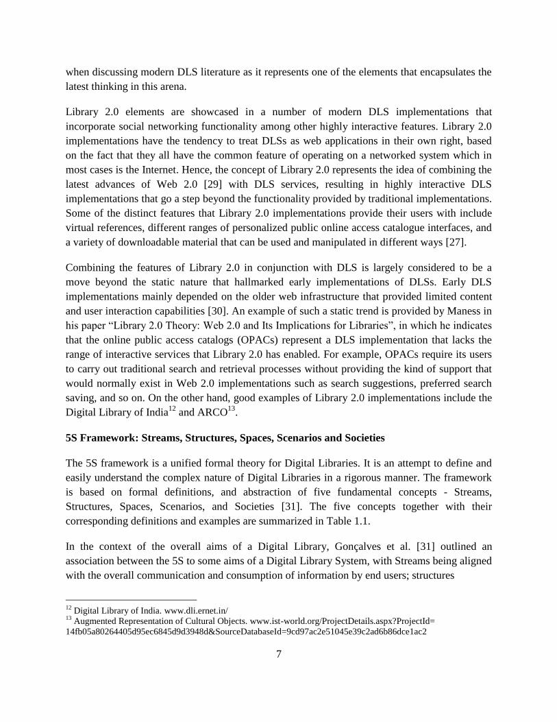
5S Framework: Streams, Structures, Spaces, Scenarios and Societies
The 5S framework is a unified formal theory for Digital Libraries. It is an attempt to define and
easily understand the complex nature of Digital Libraries in a rigorous manner. The framework
is based on formal definitions, and abstraction of five fundamental concepts - Streams,
Structures, Spaces, Scenarios, and Societies [31]. The five concepts together with their
corresponding definitions and examples are summarized in Table 1.1.
In the context of the overall aims of a Digital Library, Gonçalves et al. [31] outlined an
association between the 5S to some aims of a Digital Library System, with Streams being aligned
with the overall communication and consumption of information by end users; structures
12
Digital Library of India. www.dli.ernet.in/ 13
Augmented Representation of Cultural Objects. www.ist-world.org/ProjectDetails.aspx?ProjectId=
14fb05a80264405d95ec6845d9d3948d&SourceDatabaseId=9cd97ac2e51045e39c2ad6b86dce1ac2
8
S-Concept Concept Definition Examples
Streams Streams represent a sequence of elements
of an arbitrary type Text, video, audio, software
Structures Structures specify the organisation of
different parts of a whole Collection, document, metadata
Spaces Spaces are sets of objects with associated
operations, that obey certain constraints User interface, index
Scenarios Scenarios define details for the behaviour
of services Service, event, action
Societies Societies represent sets of entities and the
relationship between them
Community, actors, relationships,
attributes, operations
Table 1.1 Summary of Key Aspects of the 5S Framework
supporting the organization of information; spaces dealing with the presentation and access to
information in usable and effective ways; scenarios providing the necessary support for defining
and designing services and Societies defining how a Digital Library satisfies the overall
information needs of end users.
However, Candela et al. [2] state that the 5S framework is very general-purpose and thus less
immediate. The 5S framework is also arguably aimed at formalizing the Digital Library aspects.
DELOS Digital Library Reference Model
The DELOS Network of Excellence on Digital Libraries was a European Union co-funded
project aimed at integrating and coordinating research activities in Digital Libraries published a
manifesto that establishes principles that facilitate the capture of the full spectrum of concepts
that play a role in Digital Libraries [3]. The result of this project was a reference model - the
DELOS Digital Library reference model - comprising of a set of concepts and relationships that
collectively attempt to capture various entities of the Digital Library universe.
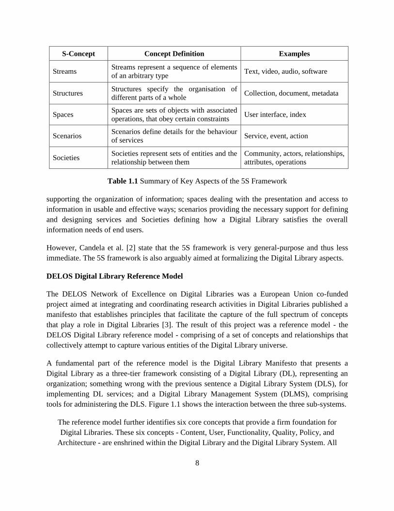
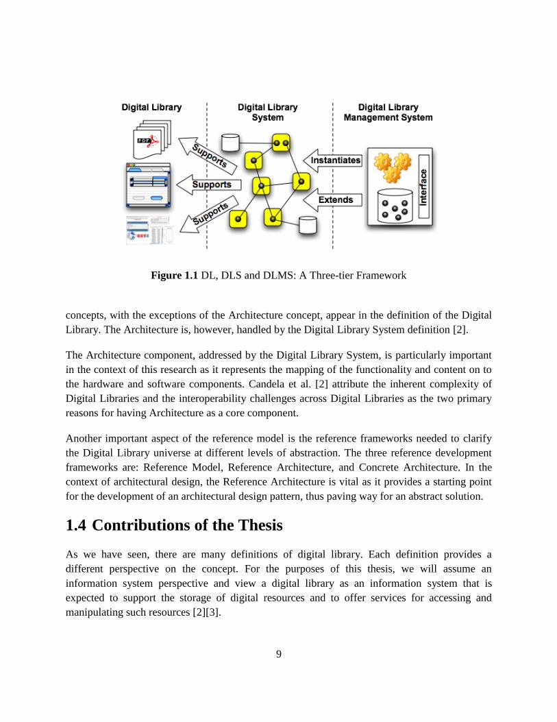
A fundamental part of the reference model is the Digital Library Manifesto that presents a
Digital Library as a three-tier framework consisting of a Digital Library (DL), representing an
organization; something wrong with the previous sentence a Digital Library System (DLS), for
implementing DL services; and a Digital Library Management System (DLMS), comprising
tools for administering the DLS. Figure 1.1 shows the interaction between the three sub-systems.
The reference model further identifies six core concepts that provide a firm foundation for
Digital Libraries. These six concepts - Content, User, Functionality, Quality, Policy, and
Architecture - are enshrined within the Digital Library and the Digital Library System. All
9
Figure 1.1 DL, DLS and DLMS: A Three-tier Framework
concepts, with the exceptions of the Architecture concept, appear in the definition of the Digital
Library. The Architecture is, however, handled by the Digital Library System definition [2].
The Architecture component, addressed by the Digital Library System, is particularly important
in the context of this research as it represents the mapping of the functionality and content on to
the hardware and software components. Candela et al. [2] attribute the inherent complexity of
Digital Libraries and the interoperability challenges across Digital Libraries as the two primary
reasons for having Architecture as a core component.
Another important aspect of the reference model is the reference frameworks needed to clarify
the Digital Library universe at different levels of abstraction. The three reference development
frameworks are: Reference Model, Reference Architecture, and Concrete Architecture. In the
context of architectural design, the Reference Architecture is vital as it provides a starting point
for the development of an architectural design pattern, thus paving way for an abstract solution.
1.4 Contributions of the Thesis
As we have seen, there are many definitions of digital library. Each definition provides a
different perspective on the concept. For the purposes of this thesis, we will assume an
information system perspective and view a digital library as an information system that is
expected to support the storage of digital resources and to offer services for accessing and
manipulating such resources [2][3].
10
Digital resources range from simple media objects (digital texts, images, videos and the like) to
composite objects of various kinds.
The basic services expected from a digital library should allow users to perform the following
tasks:
identify a resource of interest, in the sense of assigning to it an identifier;
access a resource;
describe a resource of interest according to some vocabulary;
create a complex digital resource by re-using existing resources;
discover resources of interest based on their metadata.
In order to design and implement a digital library system supporting the above services, one
needs a data model and a query language.
In this thesis, our starting point is the model and query language developed by our research team
in the context of three European projects:
2002-2004: SeLeNe : Self eLearning Networks (Contrat IST-2001-39045)
(http://www.dcs.bbk.ac.uk/selene/).
2004-2007: FP6 DELOS Network of Excellence for Digital Libraries (Contract : G038-
507618) (http://www.delos.info/partners.html)
2010-2012 Projet ASSETS: Advanced Search Services and Enhanced Technological
Solutions for the European Digital Library (CIP-ICT PSP-2009-3, Grant Agreement no
250527) (http://www.assets4europeana.eu/)
The theoretical aspects of the model and query language have been presented in [32][33]. The
objective of this thesis was twofold:
1/ Show the feasibility of the theoretical model by designing and implementing a simplified form
of the model and query language. This was the main objective.
2/ Contribute to the theoretical model itself by studying an important community service, namely
content generation by re-use.
The theoretical model used in this thesis is inspired by the Web, which forms a solid, universally
accepted basis for the notions and services expected from a digital library. More precisely, the
notion of resource was first introduced in the context of the Web and constitutes the cornerstone
of the Web architecture [35], along with the notions of identifier and representation of a
resource. In fact, today, the Web supports the identification of resources (through URIs), their
11
access (through Web servers), their creation (in the form of HTML documents) and their
discovery (through search engines).
However, when a URL is used as an identifier, access and identification are blurred by the Web,
as the URL provides both the reference to the resource and an access path to it. More
importantly, a core notion of digital libraries is missing from the current Web architecture,
namely the notion of description of a resource. The Semantic Web14
does provide languages for
expressing descriptions, and mechanisms for querying such descriptions; however, such
languages and querying mechanisms do not play any significant role in the context of the Web,
at present, because in the current Web architecture there is no means to connect resources and
descriptions.
Our model tries to overcome these drawbacks by:
(a) making a clear distinction between identification of a resource and access to it;
(b) providing a way of modeling descriptions as independent resources;
(c) relating descriptions to the described resources; and
(d) providing a query language for discovering resources based on their descriptions.
In our model, we use relations to express the basic facts stored in a digital library, and rely on a
first-order theory to derive information implicit in the given facts, under certain axioms. The
choice of logic is motivated by the desire of generality, which includes freedom from any
technological constraint.
To demonstrate the feasibility of the model developed by our research team, and its suitability
for practical applications, we provide a full translation of the model to RDF [36] and of the query
language to SPARQL [37]. The choice of RDF is due to the fact that it is a generally accepted
representation language in the context of digital libraries and the Semantic Web.
In this context, as stated earlier, one of the major aims of this thesis is to design and implement a
simplified form of the model developed by our research team. A RDF and SPARQL-based
digital library system has been developed by using Java technologies; a Java API for RDF called
Jena15
and the Google Web Toolkit framework16
. The system architecture consists of:
14
SemanticWeb - W3C. www.w3.org/standards/semanticweb/ 15
Apache Jena. jena.apache.org/ 16
Google Web Toolkit (GWT). developers.google.com/web-toolkit/
12
A storage layer that includes a storage for storing digital resources inside the digital library; a
reference table for storing and managing associations between identifiers and digital
resources; and a metadata base for storing the metadata and the content of digital resources.
In the actual implementation, the facts in RDF triple format are stored in a RDF Store.
A business logic layer that contains the business logic of the application. It consists of four
basic modules as follows: triple manipulation module, query evaluation module, translator
engines, persistency management module.
A service layer that controls the communication between the client logic and the server logic,
by exposing a set of services (operations) to the client side components. For example,
predicate manipulation services such as creating, editing, updating, and deleting predicates;
as well as query services that provide the basic methods for evaluating conjunctive queries.
A user interface that allows the user of the digital library to: search and/or browse resource
collections; view the metadata records that describe a resource; create, read, update and
delete metadata of resources; as well as express conjunctive queries in our query language to
discover information from the digital library.
During the thesis work, the system was built, tested, and debugged locally and then deployed on
Google App Engine (GAE)17
. In the future, it can be expanded to become a full fledged digital
library management system.
1.5 Outline of the Thesis
The rest of this thesis is organized as follows:
Chapter 2 is devoted to the presentation of the model developed by our research team. It
introduces the notions of digital library, and a first-order theory whose axioms give the formal
semantics of the notions introduced and, at the same time, provide a definition for the knowledge
that is implicit in a digital library. The theory is then translated into a datalog program that, given
a digital library, allows to efficiently derive the knowledge implicit in the digital library. The
query language of the model is also presented, allowing users to discover knowledge from a
digital library.
Chapter 3 introduces the key technologies that we use for developing the application. They
include: AJAX, the leading technology in Web 2.0; Java Servlet, the Java solution for providing
web-based services; RDF, SPARQL and SPARQL Update, they are some key technologies of
Semantic Web; Jena, a Java framework for building Semantic Web applications; and Google
Web Toolkit, a software development kit for developing client-side web applications.
17
Google App Engine. developers.google.com/appengine/
13
Chapter 4 discusses the implementation of the model based on the Semantic Web technology. It
includes translating from the model to RDF and mapping the query language of the model to
SPARQL. The translation of the model into RDF is provided by defining a new vocabulary,
called RDFDL, for expressing digital libraries in RDF. Meanwhile, mapping the query language
of the model to SPARQL is carried out by separating the queries of the model into different
cases to facilitate translating them into SPARQL.
Chapter 5 covers a specific implementation based on our model. This begins with showing the
functional specification of the system that must be satisfied. Consequently, this describes the
complete system’s architecture and provides an in depth analysis of the internal functionality.
The system has been implemented as a Web application using the Google Web Toolkit (GWT)
platform. Also in the chapter, the user interface of the system is presented and described in detail
how to use it.
Chapter 6 presents our contribution to content generation by reuse. This is mostly theoretical
work done to complement the model and query language developed by our research team. Its
incorporation in the implemented system is left to future work.
Chapter 7 contains concluding remarks and future work.
14
Chapter 2
2 A Data Model for Digital Libraries
In this thesis, our starting point is the model and query language developed by our research team
in the context of three European projects:
2002-2004: SeLeNe : Self eLearnig Networks (Contrat IST-2001-39045)
(http://www.dcs.bbk.ac.uk/selene/).
2004-2007: FP6 DELOS Network of Excellence for Digital Libraries (Contract : G038-
507618) (http://www.delos.info/partners.html)
2010-2012 Projet ASSETS: Advanced Search Services and Enhanced Technological
Solutions for the European Digital Library (CIP-ICT PSP-2009-3, Grant Agreement no
250527) (http://www.assets4europeana.eu/)
The theoretical aspects of the model and its translation in RDF have been carried out in a
companion thesis [34] and they are presented in [32][33]. They are summarized in this and the
following chapter because they serve as a basis for the main contributions of this thesis which
are:
1/ Show the feasibility of the theoretical model by designing and implementing a simplified form
of the theoretical model and query language.
2/ Contribute to the theoretical model itself by studying an important community service, namely
content generation by re-use.
This Chapter is organized as follows. Section 2.1 introduces a few important digital library
notions such as Resource, Content and Metadata. Section 2.2 gives the formal definition of
digital library. Section 2.3 defines the axioms to capture the implicit knowledge of a given digital
library. Section 2.4 defines formally the notion of complete digital library. Section 2.5 defines
the language for querying a digital library.
15
2.1 Digital Library: An Informal Introduction
2.1.1 Resource
In a digital library, the basic notion is that of a resource, which we understand as anything that
can be identified. This notion is borrowed from the Web architecture where the term resource ―is
used in a general sense for whatever might be identified by a URI‖ [35].
In the Web architecture, a further distinction is made between information resources and non-
information resources:
The distinguishing characteristic of information resources is that ―all of their essential
characteristics can be conveyed in a message‖ [35]. Examples of information resources
include Web pages, images, product catalogs, and so on are identified as information
resources.
Other things, such as cars and trees, are resources too, although they are not information
resources, because their essence is not information.
However, the definition of information resource is quite controversial [38][39][40]. The
definition of information resource does not allow to clearly separate resources that are
information resources from resources that are not. For instance, it does not allow to deciding
whether the World Wide Web Consortium is, or is not, an information resource. This is due to
the fact that the definition is expressed in terms such as ―content‖ and ―can be conveyed‖ whose
meaning is not always obvious.
To avoid ambiguity, in our model we do not follow the distinction between information
resources and non-information resources as in the Web architecture. Rather, we distinguish
between digital and non-digital resources.
A digital resource is a piece of data in digital form such as a PDF document, a JPEG image, a
digitized text and so on.
A non-digital resource is any resource that is not in digital form. Non-digital resources can be
physical objects such as the Eiffel Tower, or conceptual entities such as the Renaissance.
Digital resources can be accessed by means of suitable software. For example, a PDF resource
can be accessed by using a program that correctly interprets the encoding of the resource; the
result is a readable document. Similarly, a JPEG resource can be accessed by using a program
that correctly interprets the pixel encoding; the result is an image. We will denote the result of
accessing a resource r as acc(r):
16
We assume that whenever a user inserts a digital resource r into the digital library, he also
provides a mechanism for accessing r. Moreover, we assume that this mechanism is the only one
available for accessing r. We note that the access mechanism of a resource may require several
steps, and each step may need accessing resources other than r. For instance, an image viewer
might need to run a graphic package in order to produce its result. Likewise, a document viewer
may need font definitions in order to properly display documents. However, modeling how
resource accessing works, lies outside the scope of our model.
Informally, we view a digital library as an information system that consists of two components:
(a) a set of digital resources that the digital library stores (usually complex media objects); and
(b) knowledge about resources that are stored in the digital library, and possibly about resources
that reside outside the digital library but are relevant to the purposes of the digital library. Each
of these two components may be missing from the digital library. For example, one can conceive
of a digital library storing only a set of digital resources, without storing any knowledge about
the resources. An album of personal pictures uploaded from a digital camera without any
annotation, is an example of such a library – even though the only thing a user can do with it, is
to browse (i.e. access) the pictures.
Similarly, one can conceive of a digital library that contains just knowledge about resources
without storing any resource. A notable example of such a digital library is Europeana1, the
European digital library, which (at least in its present form) stores only metadata.
In this thesis, we assume that a digital library stores both, digital resources and knowledge about
the stored resources (as well as knowledge about not stored resources).
2.1.2 The Reference Table of a Digital Library
In order to express knowledge about resources, we need means for referring to them. These
means are the identifiers; we call identifiers the digital resources used as references to other
resources in a digital library. ―An identifier embodies the information required to distinguish
what is being identified from all other things within its scope of identification‖ [41]. The
Uniform Resource Identifier (URI): Generic Syntax [41] further emphasizes that:
An identifier should not be assumed that it defines or embodies the identity of what is
referenced, though that may be the case for some identifiers.
It should not be assumed that a system using identifiers will access the resource identified: in
many cases, identifiers are used to denote resources without any intention that they be
accessed.
1 www.europeana.eu
17
For example, a teacher setting up a digital library on Renaissance art, may need to express
knowledge about the famous painting Mona Lisa. The painting itself is a non-digital resource,
therefore the only way to record knowledge about it is to use a digital resource as an identifier of
the painting (e.g. the string ―Mona Lisa‖). Then, the teacher can express knowledge about Mona
Lisa using that identifier.
Similarly, if the teacher wants to express knowledge about a thumbnail of Mona Lisa, he can
again select a digital resource as an identifier of the thumbnail (e.g. the string ―My Mona Lisa‖)
and use that identifier for expressing knowledge about the thumbnail.
Of course, in some cases digital resources themselves (and not their identifiers) are used directly
in knowledge statements. This is typically the case of short pieces of text that are used for
expressing names or short descriptions. For example, the Resource Description Framework
(RDF) [42] offers literals as digital resources to be used in knowledge statements (i.e. triples)
and URIs as identifiers of resources.
In order to obtain a clean mathematical model, we allow only identifiers in knowledge
expressions. This choice does not compromise the usability of the digital library, as identifiers
are only used internally and the interaction with the user is mediated by an interface: when the
user inserts knowledge statements containing digital resources, the interface replaces the
resources by their identifiers; conversely, when the digital library delivers knowledge to the user,
identifiers are replaced by the identified resources. In the rest of this section, we explain how the
association between identifiers and identified resources is maintained.
In order to fulfill its purpose, an identifier cannot refer to two different resources at the same
time. This sets up a function from identifiers to the referred resources. We shall call this function
the reference function of the digital library, and we shall denote it by ref. Therefore, ref(i) = r
means that identifier i refers to resource r. Conceptually, we will think of the reference function
as being a binary table whose left column contains the identifiers and whose right column
contains the referred resources.
We note that the reference function does not have to be injective; in other words, two different
identifiers may refer to the same resource. This allows users of a digital library to create co-
references (i.e. different references for the same resource).
Co-reference information is very important for the operation of a digital library and should be
stored and managed appropriately. In fact, when two or more identifiers co-refer, and moreover
they reside in different digital libraries, the management of co-reference becomes a non trivial
problem [43]. However, the treatment of co-reference lies outside the scope of this thesis.
18
We assume that the role of identifiers is solely to stand as surrogates of resources of interest in
the digital library. In other words, we assume that the users of the digital library do not need to
store any knowledge about an identifier (other than its association to the resource it identifies). In
particular, there is no need to identify identifiers.
It is very important to note that the set of identifiers is dynamic (i.e. it changes over time).
Indeed, when a new resource becomes of interest to a user, a digital resource is selected as an
identifier and the association between this identifier and the new resource is inserted into the
reference function. Conversely, when a resource ceases to be of interest, the association between
that resource and its identifier(s) is deleted from the reference function (but the resource and its
identifier(s) can remain as resources in the library).
Our treatment of identifiers is different from that of the Web, where the set of identifiers (i.e. the
set of URIs) is fixed a-priory by a syntax: any digital resource that satisfies the syntax is called a
URI and URIs are the only identifiers on the Web. In contrast, we do not fix the set of digital
resources to be used as identifiers. Rather, whenever an identifier is needed the user just picks up
a digital resource (that is not currently used as an identifier) and makes it into an identifier. Yet,
our approach is compatible with that of the Web in the sense that the treatment of identifiers by
the Web can be seen as a special case of our approach.
The question arises how to distinguish between the two roles that a digital resource can play,
namely whether the resource is used as a digital resource or as an identifier. In a programming
language like Lisp, if an atom is quoted then it is used as content, and if it is not quoted then it is
used as an identifier. For example, the character a denotes the value referred to by a, seen as an
identifier, whereas (quote a) denotes the character a. The same approach is used in natural
language, where the distinction between the two roles is done again by using quotes. Although
we could use the same convention in our model, we will not do so because context will always
determine which role is meant. As a consequence, we achieve a twofold objective: we keep the
model simple and we prevent identifiers from referring to other identifiers, as desired.
Regarding insertions and deletions of associations in the reference function, they are treated
differently, depending on whether or not the referred resources reside in the digital library. If the
referred resource resides in the digital library, then the association can be stored in the library. If
the referred resource resides outside the digital library (i.e. it is a non-digital resource, or a digital
resource not stored in the digital library), then the association between the identifier and the
resource cannot be stored: it only exists in the mind of the creator of the association. This is in
fact the reason why identifiers of such resources should be chosen carefully to help users recall
easily the referred resource. For example, the string ―Mona Lisa‖ would be a good identifier for
the painting.
19
As a general practice, one should rely on the identifiers provided by the so called authorities. For
authors, a very well known authority is the Virtual Authority File (VIAF2), whereas for
geographical resources a very well known authority is the Getty Thesaurus of Geographic Names
(TGN3).
As we mentioned above, not all reference associations can be stored in the digital library. We
shall refer to the set of all stored reference associations as the reference table of the digital
library. Note that the reference table represents a restriction of the reference function. Indeed,
every association recorded in the reference table is an association under the reference function.
However, if an association is not in the reference table, this does not imply that the association is
not in the reference function. In other words, we are modeling under the so-called open-world
assumption [44].
The reference table is one of the two main components of a digital library. The other component
is the metadata base, presented in the following section.
2.1.3 The Metadata Base of a Digital Library
The metadata base of a digital library contains two kinds of knowledge that a user can express
about a resource: the metadata and the content of the resource.
The metadata of a resource consists of one or more descriptions of the resource.
The content of a resource consists of one or more other resources that make up the resource.
These two basic notions are introduced below.
Metadata
In order to perform its tasks, the digital library needs to represent, store and process a certain
amount of information about the resources in its scope. For example, in a personal digital library
containing a number of pictures, the following pieces of information would be relevant:
(a) resolution, delivered to the digital library by the imaging device together with the picture, and
stored for accessing purposes;
(b) name of the creator, directly provided to the digital library by the creator himself, and stored
for interpretation or discovery purposes;
2 www.viaf.org
3 www.getty.edu/research/tools/vocabularies/tgn/index.html
20
(c) color histogram, derived by image processing software and stored for similarity-based
discovery purposes; and
(d) classification, according to some pre-defined ontology, provided by a knowledge curator and
stored for interpretation or discovery purposes.
In this thesis, we are not interested in the provenance of this information, how it is captured, or
how it reaches the digital library. We are only interested in modeling the information itself in the
form of what we call a description. Moreover, for reasons that will become clear later, we
decouple descriptions from the resources they might be associated to, by providing a separate
mechanism for associating descriptions to resource identifiers.
We define a description to be a set of classes and/or property-value pairs. For example, the set
{Crime, (Author, Agatha Christie)} is a description; it can be attached to Agatha Christie’s ―And
Then There Were None‖. The set {Paperback, (Price, 10 euros)} is a different description that
can be attached to the same book. In other words, a resource can be associated with one or more
descriptions. Intuitively, each description represents a different point of view. In our previous
example, the first description represents the librarian’s viewpoint, while the second description
represents the re-seller’s viewpoint.
We argue that the converse may also be true, i.e. the same description may be associated to more
than one resource. For example, the description {Image, (Subject, Landscape)} can be associated
to either a postcard or a painting depicting a landscape. Based on this observation, we argue that
descriptions are distinct from the resources they may be associated to, therefore they are
resources in their own right, endowed with their own identity. This view complies with the view
of metadata expressed by the DELOS Reference Model [2][3] according to which metadata is
indeed a role that a certain resource may play in a specific context. Our view also complies with
the OAI-ORE model4, which defines resource maps as distinct resources that provide
descriptions of aggregations.
Formally, we model descriptions by defining two relations as follows:
DescCl, a ternary relation in which a triple (d, s, c) expresses the fact that class c over
schema s belongs to description d. A class can belong to zero, one or more descriptions and a
description can contain zero, one or more classes.
DescPr, a quaternary relation in which a quadruple (d, s, p, i) expresses the fact that the
property-value pair (p, i), where p is over schema s, belongs to d. A description can contain
one or more property-value pairs. Conversely, a property-value pair can belong to zero, one
or more descriptions.
4 www.openarchives.org/ore/
21
The association between resources and their descriptions is modeled as a binary relation:
DescOf, in which a pair (d, i) expresses the fact that d identifies a description of the resource
identified by i.
For example, the following tuples model the fact that, the resource identified by i is a book,
authored by t :
( )
( )
( )
In the above representation, both the class Book and the property Author are over the same
schema s:
As already pointed out, a description can be associated to zero, one or more resources, and a
resource can be associated to zero, one or more descriptions.
The intended semantics of the DescOf relation is that, a pair (d, i) means the resource identified
by i is an instance of the classes contained in d, and each property-value pair in d gives an
attribute of the resource identified by i. Of course a description is simply a means for describing
a resource, and the above interpretation is just a recommendation about the use of descriptions.
However, there is no way to ensure that users will follow this recommendation.
Notice that the model allows users to associate a description d1 to a description d2, the latter seen
as a resource. This is done by inserting the pair (d1, d2) into DescOf; d1 might state, for instance,
provenance and trust of d2.
We use the term metadata of a resource to mean the set of all descriptions associated to that
resource.
Note that in the above definitions of the two basic relations DescCl and DescPr, we have used the
concepts of class, property and value. These are abstract notions of a linguistic nature, hence
non-digital resources referred to via identifiers and defined in so-called schemas.
Our definition of schema is similar to the one used in object-oriented models, conceptual
modeling languages [45], and more recently in the Semantic Web through RDFS [42].
We view a schema as a non-digital resource and we capture the knowledge in a schema as
follows:
22
SchCl, a binary relation defined to capture the association between classes and schemas. A
pair (s, c) in SchCl expresses the fact that the class identified by c belongs to the schema
identified by s. A class can belong to one or more schemas and a schema can contain zero,
one or more classes.
SchPr, a binary relation defined to capture the association between properties and schemas. A
pair (s, p) in SchPr expresses the fact that p belongs to s. A property can belong to one or
more schemas and a schema can contain zero, one or more properties.
IsaCl, a ternary relation defined to capture the is-a relation between classes. A triple (s, c1, c2)
in IsaCl expresses the fact that, in schema s, c1 is a sub-class of c2. A class can have zero, one
or more sub-classes and zero, one or more super-classes.
IsaPr, a ternary relation defined to capture the is-a relation between properties. A triple (s, p1,
p2) in IsaPr expresses the fact that, in schema s, p1 is a sub-property of p2. A property can
have zero, one or more sub-properties and zero, one or more super-properties.
Dom, a ternary relation defined to capture the domains of properties. A triple (s, p, c) in Dom
expresses the fact that in schema s, class c is a domain of property p. A property can have
zero, one or more classes as domains, and a class can be a domain for zero, one or more
properties.
Ran, a ternary relation defined to capture the ranges of properties. A triple (s, p, c) in Ran
expresses the fact that in schema s, class c is a range of property p. A property can have zero,
one or more classes as ranges, and a class can be a range for zero, one or more properties.
A common practice in digital libraries is to mix in the same description classes and properties
coming from different schemas; for example, within the same description one may mix the title
property from Dublin Core [46] and the P55 has current location property from CIDOC CRM
[47] (for example to describe a painting). Our model clearly supports this practice.
We conclude this section by observing that in our model the structure of a description is very
simple, in fact just a set. In reality, descriptions may have a much richer structure. For example, a
MARC record5 includes labels, directories, fields, sub-fields, and more. In our approach we
retain only the essential characteristics of a description and its relationships with the other
elements of the model (in order not to be hindered by unnecessary details). The model can be
easily extended for practical use, and in fact no significant effort is required to add the machinery
for modeling, for instance, MARC records.
Content
5 MARC stands for MAchine Readable Cataloguing, and is a very popular metadata format, adopted, amongst
others, by the Library of Congress. ISO Standard 2709 is based on MARC.
23
In computer science, the term ―content‖ is used with many different meanings. In this work, by
content of a resource r we mean the set of other resources that make up r from an application
point of view; each such resource is called a part of r. For example, each chapter of a book (seen
as a resource in its own right) can be seen as a part of that book. Similarly, each painting in an
exhibition of paintings can be seen as a part of the exhibition.
Not all resources can have parts. We assume that classes, properties, schemas and descriptions
cannot have parts, nor can be parts of other resources. We shall call all other kinds of resources
composable. Notice that also physical resources are composable (through their identifiers).
Formally, content is represented by a binary relation:
PartOf, in which a pair (i, j) expresses the fact that i identifies a composable resource which
is part of the composable resource identified by j. A resource can have zero, one or more
resources as content, and can belong in the content of zero, one or more resources.
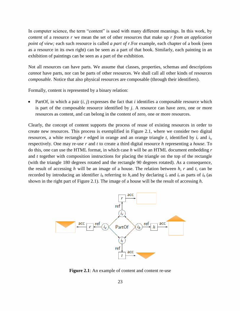
Clearly, the concept of content supports the process of reuse of existing resources in order to
create new resources. This process is exemplified in Figure 2.1, where we consider two digital
resources, a white rectangle r edged in orange and an orange triangle t, identified by ir and it,
respectively. One may re-use r and t to create a third digital resource h representing a house. To
do this, one can use the HTML format, in which case h will be an HTML document embedding r
and t together with composition instructions for placing the triangle on the top of the rectangle
(with the triangle 180 degrees rotated and the rectangle 90 degrees rotated). As a consequence,
the result of accessing h will be an image of a house. The relation between h, r and t, can be
recorded by introducing an identifier ih referring to h, and by declaring ir and it as parts of ih (as
shown in the right part of Figure 2.1). The image of a house will be the result of accessing h.
Figure 2.1: An example of content and content re-use
24
Notice that one can combine r and t in a different way, by placing the triangle inside the
rectangle, to produce a new digital resource e. The result of accessing e will be an envelope, as
shown in Figure 2.1. The important thing to notice here is that, although the resources h and e
have the same content, the results of accessing them look completely different.
Roughly speaking, the same content may be used in different ways in order to produce quite
different results. One important aspect of content generation by reuse is how to generate the
description of the generated composite object by reusing the descriptions of its components. This
aspect is one of the contributions of this thesis and will be presented in Chapter 6.
In real applications, content takes more sophisticated forms, for instance offering the distinction
between re-usable vs. non-re-usable parts, or allowing to order the parts of a resource. However,
modeling content per se is outside the scope of the present thesis. Here, we are interested mainly
in highlighting the importance of content for re-usability purposes.
Indeed, creating a new resource from existing resources is tantamount to adding or removing
parts in the content of a resource. To this end, it does not really matter whether we model content
as a relation in the metadata base or more simply as a property in a description (as in fact some
metadata models do). We follow the former approach in order to have content as a first class
citizen in the model.
Independently of how content is modeled, the question arises how the metadata of the parts relate
to the metadata of the whole. In general, this relation is very difficult, if not impossible, to
determine. This is due to the fact that different descriptions may address different aspects of a
resource, and a criterion that is suitable to one aspect is not necessarily suitable to a different
aspect.
For instance, authorship calls for a union-based synthesis, in the sense that if a chapter of a book
is written by Joe and another chapter is written by Tom, it seems reasonable to infer that the
book is written by Joe and Tom, among others. On the other hand, topicality calls for a synthesis
based on common ancestors, in the sense that if a chapter of a book talks about dogs and another
chapter talks about whales, it seems reasonable to infer that the book as a whole talks about
mammals.
The approach that in our view best reflects the requirements of a digital library, is the one
presented in [70]. In that work, the authors introduce an elegant mathematical model whereby the
metadata of a composite resource consists of two parts:
(a) the metadata given by the creator of the resource, and
25
(b) a synthesis of the metadata of the parts, formalized as the least upper bound according to an
ordering between the terms making up the metadata.
The rationale behind this definition is that, besides the creator’s intention, the metadata of the
composite resource should also reflect the metadata of its parts. This is also the rationale that we
shall adopt in Chapter 7.
For example, in Figure 2.1, the creator of the composite resource h will certainly specify a house
in the associated description, and the system should complete this specification by adding the
white rectangle edged in orange and the orange triangle, thereby informing users of the library
that a white rectangle edged in orange and an orange triangle are available in the content of h. In
this way, other users will be able to re-use the contents of h for different purposes (for example,
to create an envelope).
In this thesis, we subscribe to the approach of [48], and we capture its essence as implicit
knowledge, embedded in one of the axioms of the theory introduced in the next section.
2.1.4 An Example
Consider Paul Cézanne’s painting ―LE VASE BLEU‖. This is a non-digital resource; therefore it
can only be referred from within a digital library by using an identifier. As already hinted earlier,
a good practice is to use identifiers that come from authorities. Since ―LE VASE BLEU‖ is a
popular object, there exist several identifiers for it. For the purposes of our example, let’s
consider the Wikipaintings identifier: http://www.wikipaintings.org/en/paul-cezanne/the-blue-
vase, and let’s use for convenience the symbol tbv to stand for this identifier.
As a description of ―LE VASE BLEU‖, let’s use the one found in the Joconde database of the
French Ministry of Culture6. Moreover, as an identifier of this description, let’s use its Web
identifier (i.e. the URL of the Web page showing the description), abbreviated as d for
readability. The description is displayed in Figure 2.2. We assume that the classes and properties
in d are over the schema joconde.
In order to represent this description in our model, we model every field (in blue text in Figure
2.2) as a property of d, and the value of the field as the value of the property. Some field values,
namely those in brown, are identifiers, therefore they can be directly used in our model; the
remaining property values are character strings, hence digital resources, which in our model need
to be replaced by identifiers (as already outlined in Section 2.1.2). In order to see how this is
done, let us focus on the Domaine and Titre fields. They are represented as follows:
6 www.culture.gouv.fr/documentation/joconde/fr/pres.htm
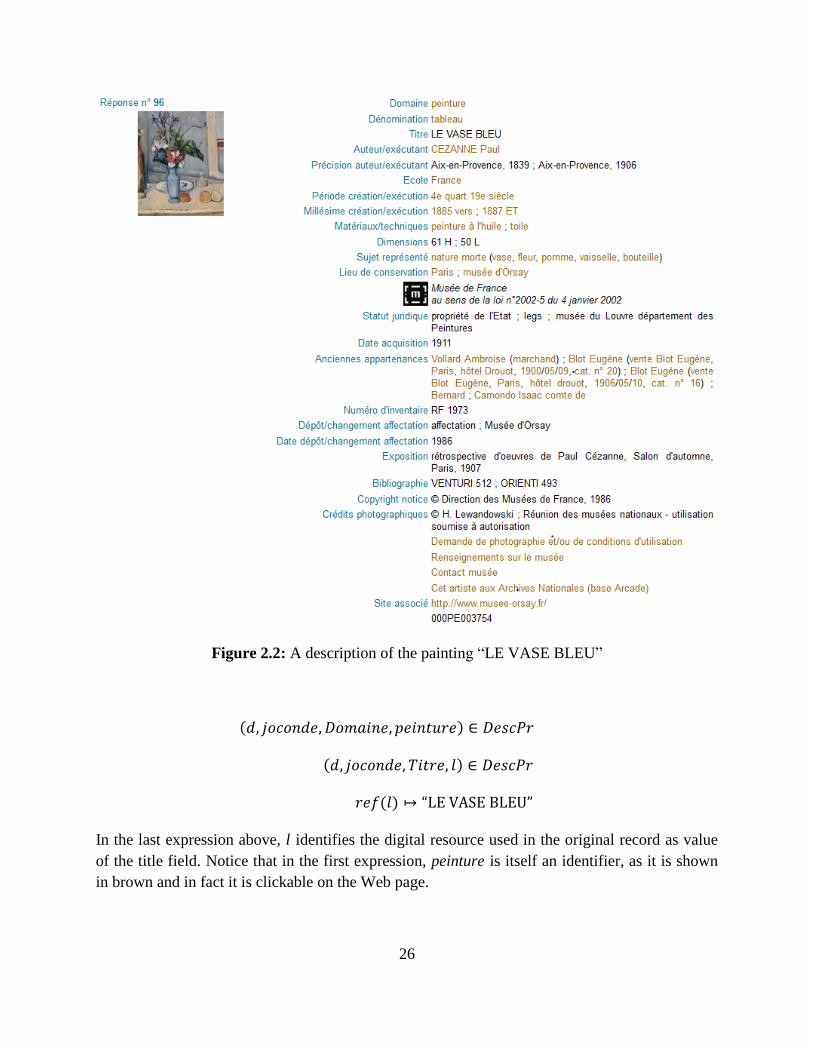
26
Figure 2.2: A description of the painting ―LE VASE BLEU‖
( )
( )
( )
In the last expression above, l identifies the digital resource used in the original record as value
of the title field. Notice that in the first expression, peinture is itself an identifier, as it is shown
in brown and in fact it is clickable on the Web page.
27
Let us now consider the field Dénomination. For the sake of the example, we understand this
field as expressing the fact that tableau is the class of the painting. In our model, this information
is represented by the tuple:
( )
The original record includes one thumbnail, identified by a URL which we abbreviated for
convenience as it . The same identifier it can be used in our model, in which case the result of
accessing the digital resource referred to by it is the image of the corresponding thumbnail. The
thumbnail can be considered to be a preview of ―LE VASE BLEU‖, and therefore we use the
property preview in order to include it in d. So we have the tuple:
( )
As a final step, we associate d to ―LE VASE BLEU‖ by inserting a pair in DescOf as follows:
( )
2.2 The Definition of a Digital Library
We can now formally define the notion of digital library based on the functions and relations
introduced so far. As already pointed out, a digital library consists of a set of digital resources,
along with knowledge about these resources, given by their content and their metadata. The
definition of digital library should reflect this fact.
First, let us define a digital library signature S to be a pair S ( ) such that:
is the set of the names of the relations introduced so far, that is:
= {SchCl, SchPr, Dom, Ran, IsaCl, IsaPr,
DescCl, DescPr, DescOf, PartOf}
is a function assigning to every name in a positive integer giving the arity of the relation,
as defined earlier (for example, ( ) while ( ) ).
Definition 1. (Digital Library) A digital library D is a pair D ( ) where:
REF, the reference table of D, is a finite function over digital resources. We recall that the
reference table REF is the stored part of the reference function ref.
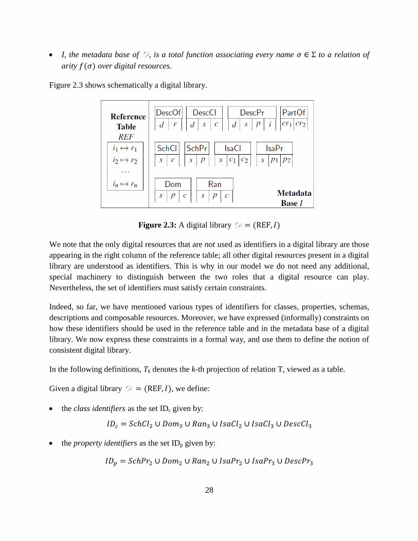
28
I, the metadata base of D, is a total function associating every name to a relation of
arity ( ) over digital resources.
Figure 2.3 shows schematically a digital library.
Figure 2.3: A digital library D ( )
We note that the only digital resources that are not used as identifiers in a digital library are those
appearing in the right column of the reference table; all other digital resources present in a digital
library are understood as identifiers. This is why in our model we do not need any additional,
special machinery to distinguish between the two roles that a digital resource can play.
Nevertheless, the set of identifiers must satisfy certain constraints.
Indeed, so far, we have mentioned various types of identifiers for classes, properties, schemas,
descriptions and composable resources. Moreover, we have expressed (informally) constraints on
how these identifiers should be used in the reference table and in the metadata base of a digital
library. We now express these constraints in a formal way, and use them to define the notion of
consistent digital library.
In the following definitions, Tk denotes the k-th projection of relation T, viewed as a table.
Given a digital library D ( ), we define:
the class identifiers as the set IDc given by:
the property identifiers as the set IDp given by:
29
the schema identifiers as the set IDs given by:
the metadata identifiers as the set IDd given by:
the composable resource identifiers as the set IDcr given by:
( ) ( )
where
It is not difficult to verify that the above definitions reflect the restrictions stated earlier on the
domains of the relations making up the metadata base. In particular, the set IDcr of the identifiers
of composable resources is given by all the identifiers occurring in the digital library except
those identifying a class, a property, a schema or a description (as already stated in Section
2.1.3). As such, composable resource identifiers can be found not only in the PartOf relation, but
also as property values in the DescPr relation, as resources with metadata in the DescOf relation,
and in the first column of the reference table.
It can also be verified that REF2, the second column of the reference table, is the only part of the
digital library that does not appear in the above definitions of IDc, IDp, IDs, IDd, and IDcr. This is
rightly so, as the digital resources found in that column are the only digital resources that are not
used as identifiers.
The sets of identifiers defined so far, collectively form the set of identifiers currently present in
the digital library.
Definition 2. (Digital Library Identifiers) Given a digital library D ( ), the set of
identifiers of D, denoted as ID, is defined as follows:
where the sets IDc, IDp, IDs, IDd, and IDcr are defined as above.
It is important to note that the set ID is dynamic: it varies depending on insertions and deletions
of tuples in the reference table and in the metadata base of the digital library. However, one
should make sure that such ―dynamicity‖ does not violate the basic property of an identifier,
namely that an identifier identifies one and only one resource. Hence the following definition of
consistency:
30
Definition 3. (Consistent Digital Library) A digital library D ( ) is consistent if the
sets of identifiers IDc, IDp, IDs, IDd, and IDcr are pairwise disjoint.
It is the task of the digital library management system to maintain consistency by detecting
violations of disjointness and by solving them in collaboration with the user. However, the
algorithms for carrying out these tasks lie outside the scope of this thesis. From now on we shall
assume that the digital library is consistent.
We stress that our definition of consistency captures those constraints whose violation can be
repaired only with user intervention. However, there are other constraints, whose violation can
be repaired without user intervention. These constraints express implicit knowledge that must be
present in the digital library in order for the constraints to be satisfied. In our model, we deal
with such constraints by introducing the notion of completion of a digital library.
2.3 Capturing Implicit Knowledge
Intuitively, a digital library is complete if it contains both the knowledge recorded by users (i.e.
the explicit knowledge) and the knowledge inferred from the explicit knowledge. For example, it
is well-known that is-a is a transitive relation, but there is no guarantee that a user specifying that
class c1 is-a class c2 and that class c2 is-a class c3 will also specify that c1 is-a c3. If the user does
not do so, then the knowledge that c1 is-a c3 is missing from the digital library, which may
nevertheless be consistent. Similarly, a user may state that class c belongs to a description d
without specifying that c indeed belongs to some specific schema s. Again, the lack of this
knowledge does not create inconsistency but the digital library is nevertheless incomplete
without it.
In order to capture the implicit knowledge in a digital library, we define a first-order theory
whose axioms express the constraints that are not captured by our notion of consistency. Based
on these axioms and on the inference mechanism of first-order logic, we specify precisely the
knowledge implicit in the digital library and we define a digital library to be complete if its
metadata base is a model of the theory (in the logical sense of the term).
2.3.1 The Language L
The language L of our theory is a first-order language, having no function symbols. This means
that the two functions introduced in the previous section, acc and ref, are not part of the
language: they are low level operations through which users access digital resources and identify
them, respectively. However, neither of these operations is amenable to logical treatment.
31
The variables of the language range over the types of identifiers introduced in the previous
section, thus we have:
schema variables (denoted by the letter s, optionally subscripted);
class variables (c, optionally subscripted);
property variables (p, optionally subscripted);
description variables (d, optionally subscripted);
composable resource variables (cr, optionally subscripted);
resource variables (i, optionally subscripted).
The predicate symbols of L are those contained in the digital library signature S , along with
their arity.
The formulas of L are defined according to the standard first-order syntax. Without further
complicating L (for instance by introducing sorts), we assume that formulas are formed by
using the various types of variables in the appropriate way, namely as stated in the definition of
consistent digital library (Definition 3). For example, we assume that all instances of the IsaCl
predicate symbol have a schema variable as first argument, and class variables as second and
third arguments.
2.3.2 The Axioms A
In this section we present the axioms of our theory. We shall refer to the set of axioms as A , and
to the first-order theory defined by L and A as the theory T . Table 2.1 summarizes the axioms
of our theory.
For readability, axioms are grouped by similarity, and every axiom is first stated in natural
language, then it is stated formally, and finally it is justified, where appropriate. Variables are
universally quantified, unless specified otherwise.
Schema membership axioms
The following axioms define the proper interaction between a schema and its elements.
(S1) If a property p has class c as a domain in a schema s, then s must contain both p and c :
( ) ( ( ) ( ))
(S2) If a property p has class c as a range in a schema s, then s must contain both p and c :
( ) ( ( ) ( ))
32
(S3) If c1 is a sub-class of c2 in a schema s then s must contain both c1 and c2 :
( ) ( ( ) ( ))
(S4) If p1 is a sub-property of p2 in a schema s then s must contain both p1 and p2 :
( ) ( ( ) ( ))
(S5) If a description d contains class c over schema s, then c must be contained in schema s :
( ) ( )
(S6) If a description d defines resource i as a value of property p over schema s, then p must be
contained in schema s :
( ) ( )
Schema inference axioms
Schema inference axioms capture implicit facts within schemas, all due to the sub-class and sub-
property relations.
(SI1) Sub-class is reflexive:
( ) ( )
(SI2) Sub-class is transitive:
( ( ) ( )) ( )
(SI3) Sub-property is reflexive:
( ) ( )
(SI4) Sub-property is transitive:
( ( ) ( )) ( )
(SI5) If c1 is a class over the schema s in d, and c1 is a sub-class of c2 in s, then also c2 is a class
over the schema s in d :
( ( ) ( )) ( )
33
This axiom captures the semantics of is-a relationships between classes, requiring that a
description containing class c1 also contains any super-class of c:
(SI6) If d defines i as a value of property p1 over schema s, and p1 is a sub-property of p2 in s,
then d also defines i as a p2-value:
( ( ) ( )) ( )
This axiom captures the semantics of is-a relationships between properties.
Metadata axioms
Metadata axioms capture implicit facts concerning descriptions.
(D1) If d defines i as a value of property p over schema s, and class c is a domain of p in s, then
also c over schema s is a class in d :
( ( ) ( )) ( )
This axiom captures the semantics of domain constraints.
(D2) If d describes a composable resource cr1 that is a part of another composable resource cr2,
then d describes cr2 too:
( ( ) ( )) ( )
This axiom transfers metadata from the parts to the whole. In this way, the whole inherits all
descriptions of its parts, besides the descriptions defined explicitly for it in the DescOf relation.
The rationale behind this choice has been discussed in Section 2.1.3.
2.4 Complete Digital Libraries
As it is well-known, an interpretation of a first-order language is a pair (D, Int) where D is the
domain of the interpretation and Int is the interpretation function, assigning a relation of the
appropriate arity over D to each predicate symbol in the language.
A digital library can be seen as an interpretation of L . In particular, given a digital library D
( ), the set of identifiers ID in D can be seen as the domain of the interpretation, and the
metadata base I can be seen as the interpretation function. Based on this observation, from now
on we will equate digital libraries, and in particular their metadata bases, with interpretations. As
a consequence, we have that a digital library D ( ) satisfies a sentence in L if is
true in the interpretation (ID, I).
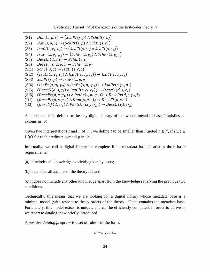
34
Table 2.1: The set A of the axioms of the first-order theory T
(S1) ( ) ( ( ) ( ))
(S2) ( ) ( ( ) ( ))
(S3) ( ) ( ( ) ( ))
(S4) ( ) ( ( ) ( )) (S5) ( ) ( ) (S6) ( ) ( ) (SI1) ( ) ( )
(SI2) ( ( ) ( )) ( ) (SI3) ( ) ( )
(SI4) ( ( ) ( )) ( )
(SI5) ( ( ) ( )) ( ) (SI6) ( ( ) ( )) ( ) (D1) ( ( ) ( )) ( ) (D2) ( ( ) ( )) ( )
A model of T is defined to be any digital library of L whose metadata base I satisfies all
axioms in A .
Given two interpretations I and of L , we define I to be smaller than , noted , if ( )
( ) for each predicate symbol p in L .
Informally, we call a digital library D complete if its metadata base I satisfies three basic
requirements:
(a) it includes all knowledge explicitly given by users;
(b) it satisfies all axioms of the theory T ; and
(c) it does not include any other knowledge apart from the knowledge satisfying the previous two
conditions.
Technically, this means that we are looking for a digital library whose metadata base is a
minimal model (with respect to the order) of the theory T that contains the metadata base.
Fortunately, this model exists, is unique, and can be efficiently computed. In order to derive it,
we resort to datalog, now briefly introduced.
A positive datalog program is a set of rules r of the form:
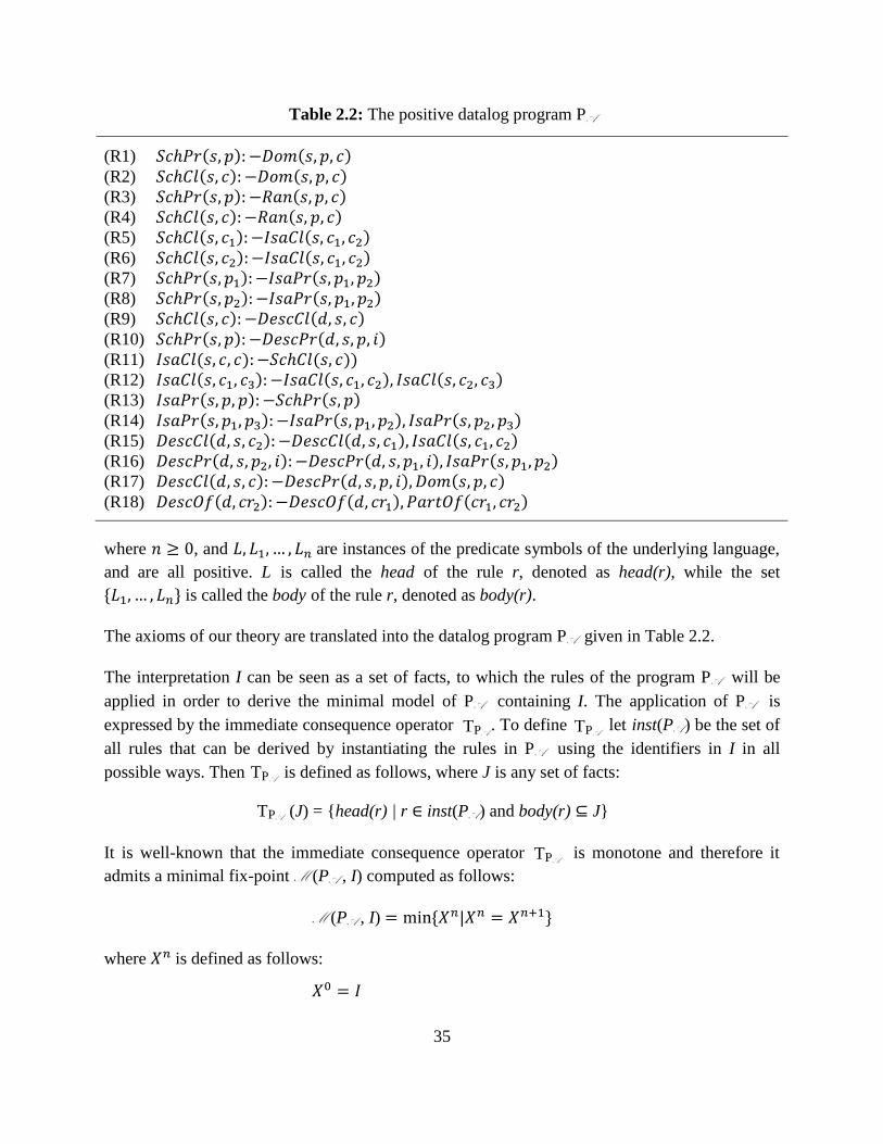
35
Table 2.2: The positive datalog program PA
(R1) ( ) ( )
(R2) ( ) ( )
(R3) ( ) ( )
(R4) ( ) ( ) (R5) ( ) ( ) (R6) ( ) ( ) (R7) ( ) ( ) (R8) ( ) ( ) (R9) ( ) ( ) (R10) ( ) ( ) (R11) ( ) ( )) (R12) ( ) ( ) ( ) (R13) ( ) ( ) (R14) ( ) ( ) ( ) (R15) ( ) ( ) ( ) (R16) ( ) ( ) ( ) (R17) ( ) ( ) ( ) (R18) ( ) ( ) ( )
where , and are instances of the predicate symbols of the underlying language,
and are all positive. L is called the head of the rule r, denoted as head(r), while the set
* + is called the body of the rule r, denoted as body(r).
The axioms of our theory are translated into the datalog program PA given in Table 2.2.
The interpretation I can be seen as a set of facts, to which the rules of the program PA will be
applied in order to derive the minimal model of PA containing I. The application of PA is
expressed by the immediate consequence operator . To define let inst(PA ) be the set of
all rules that can be derived by instantiating the rules in PA using the identifiers in I in all
possible ways. Then is defined as follows, where J is any set of facts:
It is well-known that the immediate consequence operator is monotone and therefore it
admits a minimal fix-point M (PA , I) computed as follows:
M (PA , I) * +
where is defined as follows:
PA T (J) = {head(r) | r inst(PA ) and body(r) J}
PA T
PA T PA T
PA T
36
( ) for k > 0
For more details the user is referred to [48].
From the theory of logic programming, we have the following proposition.
Proposition 1. Let I be an interpretation of L . Then, M (PA , I) is the minimal model of A that
contains I.
We are now ready to define complete digital libraries. In order to simplify notation, we will let
stand for M (PA , I).
Definition 4. (Completion, Complete Digital Library)
Let D ( ) be a digital library. The completion of D is the digital library D*
( ). Moreover, D is said to be complete if D = D*.
In practice, one starts with the facts I inserted by the users, and obtains a complete digital library
by applying the immediate consequence operator to the set I iteratively, until the result
stabilizes (i.e. a fix-point is reached). This operation is called completion. It is not difficult to see
that a complete digital library includes two kinds of knowledge:
(a) the explicit facts inserted in I by the users, and
(b) the implicit facts derived from the explicit ones through completion.
Complete digital libraries will be used to support the discovery of information.
2.5 Querying a Digital Library
In this section, first we extend L for easing the task of the user when searching a digital library
for resource discovery purposes. Then, we define formally the query language of our model and
the corresponding query answering function.
We emphasize that the digital library model presented in this thesis is a data model and not an
information retrieval model. A data model provides formal definitions of the objects that are
available for retrieval and of the query language for specifying sets of objects to be retrieved. In
addition to this functionality, an information retrieval model also provides the degree of
relevance of each object retrieved by a query. Therefore, the digital library model presented in
this thesis does not go as far as specifying the degree of relevance of retrieved objects with
respect to a query, but only which objects qualify in response to a query. As such, our digital
PA T
PA T
37
library model can be considered as an initial specification of an information retrieval model, to
be completed with the machinery necessary to produce a ranking of each query answer. The
specification of that machinery is beyond the scope of this study.
2.5.1 The Language L +
When searching a digital library for resource discovery purposes, descriptions may constitute an
obstacle between users and resources. In order to see why, let us consider a simple digital library
including scientific papers, in which authorship and aboutness are respectively expressed by
properties author and about, both defined in some schema s. In order to discover the papers that
are authored by Alfred and are about Algebra, a user of this digital library would have to use as
query the following L formula:
( )( ) ( ) ( )
( ) ( )
In this formula, x is the only free variable and stands for the sought papers. The features of the
sought papers are given in the metadata about x, therefore the formula refers to two (possibly
coinciding) descriptions d1 and d2 each dealing with one of the required features. This makes the
above formula unnecessarily cumbersome, as the two descriptions d1 and d2 have nothing to do
with the user information need. A more intuitive and straightforward way of expressing the user
information need would be to relate authorship and aboutness directly to the sought resources.
In order to ease the expression of queries, we introduce two predicate symbols that allow to
directly connect classes and property-value pairs in descriptions with the resources they are
about. These predicates are:
ClInst(i, s, c) meaning that i is an instance of class c from schema s. An assertion of this kind
is called a class instantiation.
PrInst(i1, s, p, i2) meaning that i1 has as value of property p from schema s a resource
identified by i2. An assertion of this kind is called a property instantiation.
Using these two symbols, the previous query can be expressed as follows:
( ) ( )
which is a direct translation of the user information need.
We define the extended digital library signature S + to be the pair S + ( ) where is
given by:
38
* +
and is a total function over , extending as follows:
( ) {
( )
We call L + the first-order language whose variables are those in L and whose predicate
symbols are those in the extended digital library signature, along with their arity.
We now need to capture the semantics of ClInst and PrInst by stating the axioms that relate these
two predicate symbols with the other predicate symbols of the theory. Intuitively, a resource i is
an instance of a class c if there exists some description d to that effect. But how should d be
structured in order to license the inference that i is an instance of c? There are two possibilities
only:
c is a class in a description d associated to i.
c is the range of a property p over schema s in d, and d states that i is a p-value.
Because of the semantics of range assertions, this would imply that i is an instance of c.
For property values the situation is simpler: the inference that i2 is a p-value of i1 holds just in
case i1 has a description d that has the property-value pair (p, i2). We thus have the following
axioms:
(Q1) ( ) ( ) ( )
(Q2) ( ) ( ) ( )
(Q3) ( ) ( ) ( )
We note that, as a consequence of the axioms stated so far, and using to denote logical
implication, we have that:
* ( ) ( ) ( )+ ( )
In other words, each domain c1 of a property p1 is a sub-class of each domain c2 of every super-
property p2 of p1; and the same holds for ranges, that is:
* ( ) ( ) ( )+ ( )
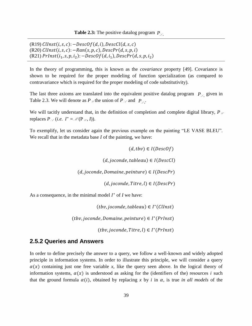
39
L + P
L + P
L + P Table 2.3: The positive datalog program
(R19) ( ) ( ) ( ) (R20) ( ) ( ) ( ) (R21) ( ) ( ) ( )
In the theory of programming, this is known as the covariance property [49]. Covariance is
shown to be required for the proper modeling of function specialization (as compared to
contravariance which is required for the proper modeling of code substitutivity).
The last three axioms are translated into the equivalent positive datalog program given in
Table 2.3. We will denote as PU the union of PA and .
We will tacitly understand that, in the definition of completion and complete digital library, PU
replaces PA (i.e. =M (PU , I)).
To exemplify, let us consider again the previous example on the painting ―LE VASE BLEU‖.
We recall that in the metadata base I of the painting, we have:
( ) ( )
( ) ( )
( ) ( )
( ) ( )
As a consequence, in the minimal model of I we have:
( ) ( )
( ) ( )
( ) ( )
2.5.2 Queries and Answers
In order to define precisely the answer to a query, we follow a well-known and widely adopted
principle in information systems. In order to illustrate this principle, we will consider a query
( ) containing just one free variable x, like the query seen above. In the logical theory of
information systems, ( ) is understood as asking for the (identifiers of the) resources i such
that the ground formula ( ), obtained by replacing x by i in , is true in all models of the
40
underlying information system. In our case, we can exemplify this principle as follows: a
resource i is returned in response to the query:
( ) ( )
just in case the ground sentence:
( ) ( )
is true in all models of the digital library. This definition can be extended to queries containing
any number of free variables, in an obvious way.
Typically, computing answers over all the models of a digital library is a computationally
difficult task, and for this reason we have defined an extended digital library to be one specific
model, namely the model obtained by applying the program PU to the interpretation I created by
the user. Now, it turns out that answering queries over the extended digital library is in general
not equivalent to answering queries over all models; but the two answers coincide for queries
that do not contain negation. We will therefore impose this syntactical restriction in the
definition of our query language. Moreover, for easing the query evaluation process, we will
further impose a structure on queries, by defining them as disjunctions of (negation-free)
conjunctive queries.
Definition 5. (Digital Library Query Language) The digital library query language Q is
inductively defined as follows:
A query term is an identifier in ID or a variable in L .
An atomic query is a formula ( ), P is a predicate symbol in such that ( )
, and t1,…, tn are query terms including at least one variable.
A simple conjunctive query is a formula , where and is an atomic
query, for all .
A quantified conjunctive query is a formula ( ) ( ) , where and is a simple
conjunctive query in which every variable xj occurs, for all .
A simple uc-query7 is a formula , where and is a conjunctive query,
for all .
A quantified uc-query is a formula ( ) ( ) , where and is a simple uc-query,
in which every variable yj occurs free, for all .
The query:
7 uc represents Union of Conjuncts (not a perfect expression because ―Union‖ belongs to set theory, whereas
―Conjunct‖ belongs to logic, but intuitively is clear).
41
( )( ( ) ( ))
is a quantified uc-query with one quantified schema variable y and one conjunctive query, which
is simple and consists of two atomic queries PrInst(x, y, author, Alfred) and PrInst(x, y, about,
Algebra). The only free variable in the query is the resource variable x; all query terms other than
x and y are identifiers. The query asks for the resources whose author and about properties,
belonging to a non-specified schema y, have as value Alfred and Algebra, respectively.
Intuitively, the user asking this query knows that there is a schema offering these properties, but
for some reason he does not mention the schema.
It is important to notice that the symbols ClInst and PrInst are only parts of the query language,
they are not included in the signature S of the digital library, which means that users are not
supposed to use them for inserting facts into the metadata base I.
As customary, we will write ( ) to denote a query in which the variables
occur.
Intuitively, the answer of a query with n free variables stated against a digital library D is the set
of n-tuples of identifiers ⟨ ⟩ such that, when every free variable is bound to the
corresponding identifier , the resulting ground formula of L + is true in the completion D* of
D. In order to make this intuition precise, we need to introduce a few concepts.
Definition 6. (Substitution) Given a non-empty set X of variables in L , a substitution for X is a
total function , assigning to each variable in X an identifier in ID. Given an atomic
query and a substitution for a subset X of the variables in , the application of to ,
denoted as , -, is the formula obtained by consistently replacing in each occurrence of every
variable by ( ).
If is defined over all the variables in , - is a ground atom, (i.e. a formula of the form
( ) where all ti’s are identifiers). A ground atom ( ) is true in a digital library
D ( ), denoted as D ( ), iff ( ) ( ).
For example, let us consider the ―LE VASE BLEU‖ example. The formula:
( )
is a substitution instance of the formula (x is a variable):
( )
For more knowledge about the substitution in logic, the reader is referred to [50].
42
Definition 7. (Answer) Let D ( ) be a digital library. The answer of a query over D,
denoted as ans( ,D), is inductively defined as follows:
If is an atomic query ( ) having as variables, then:
( ( ) D) *( ) D ( ), -
where for all , ( ) +
If is a simple conjunctive query having as variables, then:
( D) *( ) for all , D , -
where for all , ( ) +
If is a quantified conjunctive query ( ) ( ) , then:
(( ) ( ) D) = ans( [ ],
D)
for all substitutions for the quantified variables in .
If is a simple uc-query , then:
( D) = 1
ans( ,i
i m
D)
If is a quantified uc-query ( ) ( ) then:
(( ) ( ) D) =
ans( [ ], D)
for all substitutions for the quantified variables in .
To exemplify, let us consider again the ―LE VASE BLEU‖ example. In the metadata base I of
the painting, joconde is a schema and tableau is a class over joconde. A user can discover the
painting as a tableau via the query:
( )
or, as a resource whose domain is peinture via the query:
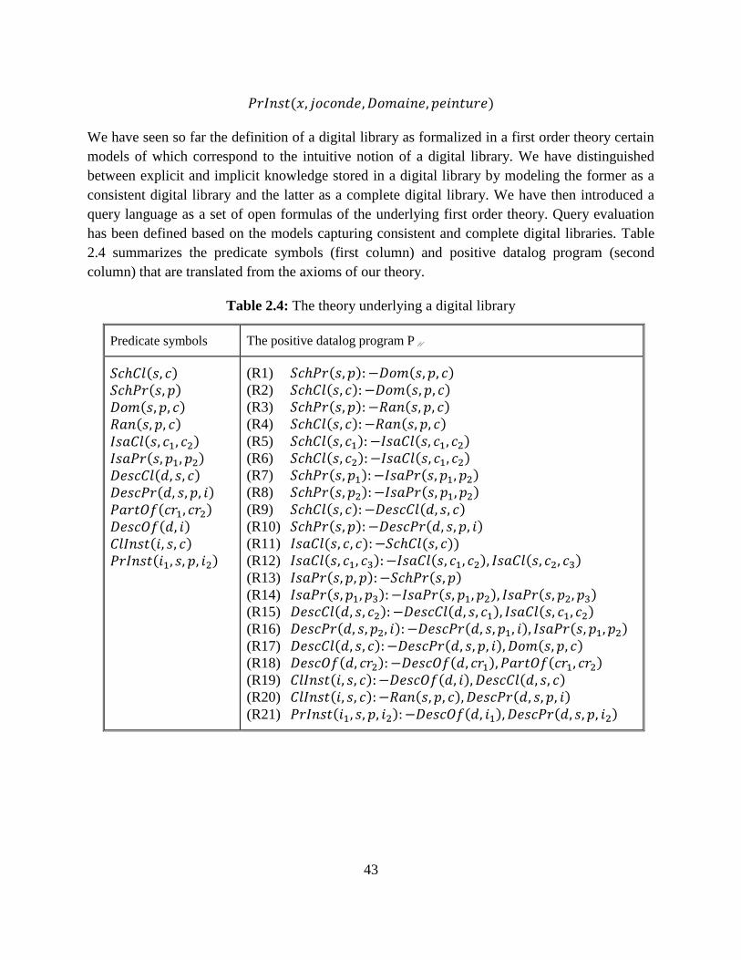
43
( )
We have seen so far the definition of a digital library as formalized in a first order theory certain
models of which correspond to the intuitive notion of a digital library. We have distinguished
between explicit and implicit knowledge stored in a digital library by modeling the former as a
consistent digital library and the latter as a complete digital library. We have then introduced a
query language as a set of open formulas of the underlying first order theory. Query evaluation
has been defined based on the models capturing consistent and complete digital libraries. Table
2.4 summarizes the predicate symbols (first column) and positive datalog program (second
column) that are translated from the axioms of our theory.
Table 2.4: The theory underlying a digital library
Predicate symbols The positive datalog program PU
( ) ( )
( ) ( ) ( ) ( ) ( ) ( )
( )
( )
( ) ( )
(R1) ( ) ( )
(R2) ( ) ( )
(R3) ( ) ( )
(R4) ( ) ( ) (R5) ( ) ( ) (R6) ( ) ( ) (R7) ( ) ( ) (R8) ( ) ( ) (R9) ( ) ( ) (R10) ( ) ( ) (R11) ( ) ( )) (R12) ( ) ( ) ( ) (R13) ( ) ( ) (R14) ( ) ( ) ( ) (R15) ( ) ( ) ( ) (R16) ( ) ( ) ( ) (R17) ( ) ( ) ( ) (R18) ( ) ( ) ( ) (R19) ( ) ( ) ( ) (R20) ( ) ( ) ( ) (R21) ( ) ( ) ( )
44
Chapter 3
3 Background technologies
In this chapter we present the standards used in this thesis, as well as the technologies used for
the implementation of our application. Firstly, in Section 3.1 we describe AJAX, the leading
technology in Web 2.0. Sections 3.2 talks about Java Servlet technology, the Java solution for
providing web-based services, that is used for the development of our application. Section 3.3,
3.4 and 3.5 describe briefly the RDF, SPARQL and SPARQL Update which define the data
model, a query language and its extension for the Semantic Web, respectively. Section 3.6 talks
about Triplestore, a purpose-built database for the storage and retrieval of Resource Description
Framework (RDF) metadata, followed by Jena (Section 3.7), a Java framework for building
Semantic Web applications. Lastly, in Section 3.8 we present Google Web Toolkit, which was
used to implement the client side of the system.
3.1 Asynchronous JavaScript and XML (AJAX)
In 1990’s user interaction in web applications was request-wait-response based, which slowed
down the user interaction considerably. The most web sites were based on complete HTML
pages where each user action required that the page should be re-loaded from the server. Each
time a page was reloaded due to a partial change, all of the content was re-sent instead of only
the changed information. This placed additional load on the server and use of excessive
bandwidth. Asynchronous JavaScript and XML (AJAX) [62] came as a boon to the web
application development, providing mechanisms for user experience similar to desktop
applications.
In the classic web application model, addressed as pre AJAX web model, user interaction
triggers an HTTP [63] request to the web server. The server performs necessary processing for
example, retrieving data or doing some calculations etc. When the processing is completed the
server returns an HTML [64] page to the client. The problem is that, during the server processing
time, the user can do nothing but wait for a page to be loaded or refreshed from the server.
AJAX increases the web page’s interactivity, speed, and usability in order to provide richer user
experience. AJAX places an AJAX engine between the client and server. This engine is written
in JavaScript and behaves like a hidden frame. The AJAX engine renders the user interface and
45
handles the communication between client and server. The client-server communication with
AJAX is asynchronous. Asynchronous communication means the client does not need to wait for
the server response. After sending the request to the server the execution in the client program
does not halt, rather the execution is continued. The response is sent to the client when it is
available. The AJAX engine sends requests to the server on behalf of the client and receives data
or responses from the server. In a web model with AJAX, the server sends small data instead of
the HTML page. The AJAX engine shows the received data or response by updating the page
partially. Thus user is free to do other interactions after sending a request to the server.
3.2 Java Servlet
A Servlet is a Java programming language class used to extend the capabilities of servers that
host applications accessed via a request-response programming model. The Servlet class is
included in JAVA EE (Enterprise Edition) and conforms to the Java Servlet API, a protocol by
which a Java class may respond to requests. Although servlets can respond to any type of
request, they are commonly used to extend the applications hosted by Web servers. Thus, it can
be thought of as a Java Applet that runs on a server instead of a browser.
Most Java servlets are designed to respond to HTTP requests in the context of a Web application.
As such, the HTTP-specific classes in the javax.servlet and javax.servlet.http packages are the
ones you’ll care about.
Each Java servlet is a subclass of HttpServlet. This class has methods that provide access to the
request and response wrappers used to handle requests and create responses.
The HTTP protocol isn’t Java-specific, of course. It is simply a specification that defines what
service requests and responses have to look like. The Java servlet classes wrap those low-level
constructs in Java classes, with convenience methods that make them easier to be used within a
Java language context. When a user issues a request via a URL, the Java servlet classes convert it
to an HttpServletRequest and send it to the target pointed to by the URL, as defined in
configuration files for the particular servlet container the user is using. When the server side has
done its work, the Java Runtime Environment packages the results in an HttpServletResponse
and then sends a raw HTTP response back to the client that made the request. When a user is
interacting with a Web app, he usually makes multiple requests and gets multiple responses. All
of them are within the context of a session, which the Java language wraps in an HttpSession
object.
46
A container, like Tomcat1, manages the runtime environment for servlets. The container can be
configured to customize the way in which the J2EE server functions. Various configurations
allow the creation of a bridge from a URL (entered by a user in a browser) to the server-side
components that handle the requests. When a web application starts, the container loads and
initializes your servlet(s), and manages their lifecycle.
By the concept ―servlet lifecycle‖, we simply mean that things happen in a predictable way when
a servlet is invoked. In other words, certain methods on any servlet will always get called in the
same order. Here’s a typical scenario:
A user enters a URL in his browser. The Web server configuration file says that this URL points
to a servlet managed by a servlet container running on the server.
If an instance of the servlet hasn’t been created yet (there’s only one instance of a servlet for an
application), the container loads the class and instantiates it.
The container calls init() on the servlet.
The container calls service() on the servlet, and passes in a wrapped HttpServletRequest and
HttpServletResponse.
The servlet typically accesses elements in the request, delegates to other server-side classes to
perform the requested service and to access resources like databases, then populates the response
using that information
If necessary, when the servlet’s useful life is done, the container calls destroy() on the servlet to
finalize it.
3.3 Resource Description Framework (RDF)
RDF (Resource Description Framework) [42] is actually one of the older specifications, with the
first working draft produced in 1997. In the earliest version, authors established a mechanism for
working with metadata that promotes the interchange of data between automated processes. This
mechanism became the base on which RDF was developed. Regardless of the transformations
RDF has undergone and its continuing maturing process, this statement forms its immutable
purpose and focal point.
The Resource Description Framework (RDF) is a language designed to support the Semantic
Web, in much the same way that HTML is the language that helped initiate the original Web.
1 Tomcat. tomcat.apache.org/
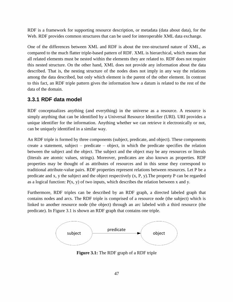
47
RDF is a framework for supporting resource description, or metadata (data about data), for the
Web. RDF provides common structures that can be used for interoperable XML data exchange.
One of the differences between XML and RDF is about the tree-structured nature of XML, as
compared to the much flatter triple-based pattern of RDF. XML is hierarchical, which means that
all related elements must be nested within the elements they are related to. RDF does not require
this nested structure. On the other hand, XML does not provide any information about the data
described. That is, the nesting structure of the nodes does not imply in any way the relations
among the data described, but only which element is the parent of the other element. In contrast
to this fact, an RDF triple pattern gives the information how a datum is related to the rest of the
data of the domain.
3.3.1 RDF data model
RDF conceptualizes anything (and everything) in the universe as a resource. A resource is
simply anything that can be identified by a Universal Resource Identifier (URI). URI provides a
unique identifier for the information. Anything whether we can retrieve it electronically or not,
can be uniquely identified in a similar way.
An RDF triple is formed by three components (subject, predicate, and object). These components
create a statement, subject – predicate – object, in which the predicate specifies the relation
between the subject and the object. The subject and the object may be any resources or literals
(literals are atomic values, strings). Moreover, predicates are also known as properties. RDF
properties may be thought of as attributes of resources and in this sense they correspond to
traditional attribute-value pairs. RDF properties represent relations between resources. Let P be a
predicate and x, y the subject and the object respectively (x, P, y).The property P can be regarded
as a logical function: P(x, y) of two inputs, which describes the relation between x and y.
Furthermore, RDF triples can be described by an RDF graph, a directed labeled graph that
contains nodes and arcs. The RDF triple is comprised of a resource node (the subject) which is
linked to another resource node (the object) through an arc labeled with a third resource (the
predicate). In Figure 3.1 is shown an RDF graph that contains one triple.
Figure 3.1: The RDF graph of a RDF triple
48
Unfortunately, recording the RDF data in a graph is not the most efficient means of storing or
retrieving this data. Instead, encoding RDF data, a process known as serialization, is usually
preferred, resulting in RDF/XML which is based on XML structures. An RDF/XML document
starts with the root element rdf:RDF. The children of this element include the data descriptions
(rdf:Description). A description element expresses a statement about one resource. The reference
to that resource can be established by a) Using the rdf:id, in case the resource is new; b) Using
the rdf:about, in case to refer to an existing resource; or c) Without using any name in order to be
anonymous. Anonymous resources belong to a special category of nodes, the blank nodes,
defined in [65].
Blank nodes are nodes that don't have a URI. When identifying a resource is meaningful, or the
resource is identified within the specific graph, a URI is given for that resource. However, when
the identification of the resource does not have sense or does not exist within the specific graph
at the time the graph was recorded, the resource is treated as a blank node. In either case, not
having a URI for the item does not mean we cannot talk about it and refer to it. Blank nodes are
graph nodes that represent a subject (or object) for which we would like to make assertions, but
have no way to address with a proper URI.
The following RDF graph describes that ―James has a friend born the 20th
of May‖. This
expression can be written with two triples linked by a blank node representing the anonymous
friend of James.
ex:James foaf:knows _:p1
_:p1 foaf:birthDate 05-20
The first triple specifies that ―James knows p1‖. The second triple specifies that ―p1 is born on
May 20th
”. Moreover, ―ex:James‖ is a named resource, which means this resource is absolutely
identified by the URI obtained by replacing the ―ex:‖ prefix by the XML namespace it stands for,
such as http://bd.lri.fr/Person#James. The ―_:p1‖ blank node represents James’s anonymous
friend, not identified by a URI. One can know by the semantics declared in the FOAF vocabulary
[FOAF] that the class of ―_:p1‖ is ―foaf:Person‖.
3.3.2 Resource Description Framework Schema (RDFS)
With its extension RDFS, RDF constitutes a so-called ―leightweight‖ ontology language,
providing basic modeling features for assertional (instance-related) and terminological
knowledge handling classes, binary relations (so-called properties), hierarchies of classes (also
referred to as taxonomies) and properties as well as domain and range specifications for
properties.
49
Specifically, RDFS is a vocabulary with specific properties for modelling meta-information on
the presented data, i.e. schema information for the data. The most important among these
properties are rdfs:label for giving humanreadable labels to URIs, rdfs:domain and rdfs:range for
denoting the domain and the range of a property, and rdfs:subClassOf for denoting subsumptions
between two concepts.
RDFS allows for the encoding of restrictions on the properties and the concepts in the data
graph. In the following example we express that the foaf:name property links a person to a
literal:
foaf:name rdfs:domain foaf:Person
foaf:name rdfs:range rdfs:Literal
...
3.4 SPARQL
For querying RDF data, the W3C standard Simple Protocol and RDF Query Language
(SPARQL) is available [37]. SPARQL is similar in spirit to SQL for databases, i.e. it allows to
query an RDF knowledge base for data which has certain properties. SPARQL graph patterns are
used in Chapter 5 for defining update patterns.
The key concept of constructing queries in SPARQL is the specification of graph patterns, i.e.
graphs which contain variables as placeholders for node or edge labels. These graph patterns are
then matched on the data graph. Each possible matching of the graph pattern on the data graph
yields a variable binding. Using these variable bindings it is possible to retrieve data with certain
properties. SPARQL allows to display the retrieved data directly or to construct new graphs
based on it.
Graph patterns are formed by a set of triples, where triple elements may be replaced by variables
(distinguished by a question mark before the identifier). Additionally to the query pattern, it has
to be specified what should be done with the results of the query. The most important possibility
is to show the bindings of specific variables in the matchings of the graph pattern (SELECT
query).
A Basic Graph Pattern is defined as a set of triple patterns. A triple pattern is an element of the
set: RDF-T ) ( ) (RDF-T ) where R denotes the set of all resources denoted by a
URI, RDF-T denotes all elements of the RDF vocabulary, i.e. the set of named resources, blank
nodes and literals and V a set of variables which is disjoint from RDF-T.
The selection criteria for data are specified using basic graph patterns (this happens in the where-
clause of the query). The basic graph pattern is matched against the data graph. Hereby, the
50
interest lies in finding those elements which the defined variables stand for. Thus, each variable
may stand for any node in the graph, the other elements in the graph pattern are matched to
nodes having the same identifier. This graph matching yields a set of variable bindings which are
then used for the result presentation. More complex conditions for the graph matchings can be
specified: it is possible to specify parts which are matched optionally or to intersect (or union)
the sets of variable bindings obtained from matching different graph patterns.
The other parts of the query specify what should be done with the matches that are found using
the search criteria in the basic graph pattern. There are several kinds of queries which specify
what should be done with the variable bindings found using the basic graph patterns. Probably
the most interesting kind of queries are select-queries, which simply present the values the
variables in the select-clause may stand for in the graph.
Consider, for example, the following bit of RDF:
person1 foaf:name “Jimmy Wales”
person1 foaf:topic_interest topic11
topic11 skos:prefLabel “Semantic Web”
person2 foaf:name “Angela Beesley”
person2 foaf:topic_interest topic11
person1 foaf:topic_interest topic12
topic12 skos:prefLabel “Machine Learning”
person3 foaf:name “Peter Parker”
person3 foaf:topic_interest topic12
As you can see, this fragment contains information on three people and the topics which they are
interested in. Now, we query for people who are interested in the topic with label ―Sematic
Web‖.
SELECT ?personName
WHERE { ?person foaf:name ?personName.
?person foaf:topic_interest ?topic.
?topic skos:prefLabel “Sematic Web”.}
The graph pattern describes a query for entities which have a foaf:name link to another node in
the graph. The subject of the first triple should also have a link of type foaf:topic_interest to
some node which itself has a link of type skos:prefLabel to the datavalue node with label
“Sematic Web”. More intuitively, the query retrieves the name of people who are interested in a
topic with label “Sematic Web”. The result of this query is a table containing all possible
bindings of the variable ?personName in matchings of the graph pattern on the data graph:
51
?personName
“Jimmy Wales”
“Angela Beesley”
Additional query types are construct, ask and describe queries. The first type of query allows for
the construction of graphs based on templates specified in the construct clause which are then
filled with the variable bindings obtained in the where clause. The ask query checks whether any
match of the where clause in the data graph exists. Finally, the describe query is used to obtain
descriptions of the selected resources without knowing what a description looks like. This is
useful in cases where the structure of the data set is not known, or only partially known, and it is
not clear which properties of the resources are of interest.
SPARQL endpoints serve as a means to make (RDF) knowledge bases accessible to humans and
machines. Besides the definition of a query language for RDF, the W3C recommendation for
SPARQL also contains the definition of a protocol for the communication between the SPARQL
endpoint and the machine/human querying the data [66].
3.5 SPARQL Update
SPARQL Update [67] is an extension of the SPARQL standard which allows for updating and
changing the data in an RDF knowledge base via the SPARQL protocol. Similar to the update
part of SQL, SPARQL Update offers functionality for adding and deleting data in a knowledge
base as well as the possibility to change data.
The basic operations are insert and delete which allow the direct insertion or deletion of a set of
triples. The set of triples to be changed is specified using a basic graph pattern (as is used in the
where-clause of the SPARQL queries). It is also possible to specify the set of triples to be
changed directly using the commands insert data (resp. delete data). There are two variants of
the delete operation: either a graph pattern is specified based on which triples which are to be
deleted are constructed, or all triples which match the graph pattern are deleted directly. It is
furthermore possible to combine delete and insert operations in a so-called modify operation, this
makes it for example possible to change properties of certain entities.
Now, imagine that we would like to add a new group – the Semantic Web Special Interest Group
(SW-SIG). All people interested in Semantic Web will be members of this group:
insert{ SW-SIG foaf:member ?person.}
where{ ?person foaf:interest ?topic.
?topic skos:prefLabel “Semantic Web”.}

52
This will add the triples SW-SIG foaf:member person1. and SW-SIG foaf:member person2. to the
knowledge base.
Additionally, the creation and deletion of graphs is possible through SPARQL Update
operations.
3.6 Triplestore
While small RDF graphs can be efficiently handled and managed in computers’ main memory,
larger RDF graphs render the deployment of persistent storage systems indispensable. RDF
stores are purpose-built databases for the storage and retrieval of any kind of data expressed in
RDF. The term RDF store is often used in order to abstract over any kind of system that is
capable of handling RDF data, including triple stores, quad stores, etc.
In this thesis, we define RDF stores as systems that allow the ingestion of serialized RDF data
and the retrieval of these data later on.
A Triplestore is a RDF Store that is specially designed for efficient storage and retrieval of a
triple2. The triplestores contain an RDF query engine. The query engines may implement
different specifications of RDF query languages. For example TDB (stands for TripleDB) is a
scalable Triplestore provided by Jena. TDB uses ARQ (An RDF Query engine, provided by
Jena) that implements SPARQL specification for querying RDF data. Sesame3 is another
Triplestore that uses a query engine which implements SeRQL4, which is another query language
for RDF. A Triplestore that supports storage of RDF graphs is known as a Quadstore. As we
know an RDF triple contains three parameters which are the Subject, the Predicate and the
Object. The quadstores associate one more parameter to a triple, which is the Graph name. This
makes the triple a quad and hence the Triplestore with graph storage support, is known as a
Quadstore. There are modules which carry out semantic reasoning on the existing knowledge to
build more knowledge and more set of triples. The Triplestore’s reasoning engine analyse the
data and identify graphs so that all data starts making a coherent semantic meaning.
Triple stores can be divided into three broad categories – in-memory, native, non-memory non-
native-based on architecture of their implementation. In-memory triple stores store the RDF
graph in main memory. Storing everything in-memory cannot be a serious method for storing
extremely large volumes of data. However, they can act as useful benchmark and can be used for
performing certain operations like caching data from remote sites or for performing inferencing.
Most of the in-memory stores have efficient reasoners available and can help solve the problem
2 TripleStore. en.wikipedia.org/wiki/Triplestore, 2009
3 www.openrdf.org/
4 www.w3.org/2001/sw/wiki/SeRQL
53
of performing inferencing in persistent RDF stores, which otherwise can be very difficult to
perform. A second, now dominant category of triple stores is the native triple stores which
provide persistent storage with their own implementation of the databases, for example Virtuoso,
Mulgara, AllegroGraph, Garlik JXT. The third category of triple stores, the non native non
memory triples stores are set up to run on third party databases for example Jena SDB which can
be coupled with almost all relational databases like MySQL, PostsgreSQL, Oracle. Recently
native triple stores due to their superior load times and ability to be optimized for RDF have
gained popularity.
3.7 Jena
As the Jena web page5 quotes ―Jena is a Java framework for building Semantic Web
applications. It provides a programmatic environment for RDF, RDFS and OWL, SPARQL and
includes a rule-based inference engine.‖
Jena has migrated from being an in-house HP project6 to an open-source project. Jena provides
APIs to parse RDF data from different formats, and write RDF in various supported formats.
Jena is based on the Java programming language and has good community support. The Jena
source code is open-source and is extensible. Jena provides sufficient documentation to work
with the Jena APIs. The Jena package also provides ARQ which is the SPARQL query engine
implementing SPARQL 1.1 specification.
ARQ makes use of core Jena APIs. ARQ is built for small scale data and uses an in-memory
implementation. The RDF data is read and maintained in a customized HashMap like data
structure, where indexes are created on all three columns i.e subject(s), predicate(p) and
object(o). These indexes help with the quick retrieval of the required data. Jena also provides the
TDB triplestore, which has been developed for large-scale RDF data storage and retrieval.
Jena TDB is a component of the Jena Semantic Web framework and available as open-source
software released under the BSD license. It can be deployed as a server on 64 and 32 bit Java
systems and accessed through the Java-based Jena API library as well as through a set of
command line utilities. Jena TDB also supports the SPARQL query language for RDF data. The
latest version of TDB was released in July 2010.
5 Apache Jena. jena.apache.org/
6 www.hp.com/
54
3.8 Google Web Toolkit (GWT)
Google Web Toolkit (GWT)7, first released in May 2006, is an open source development toolkit
for building and optimizing complex browser-based applications. Its goal is to enable productive
development of high-performance web applications without the developer having to be an expert
in browser quirks.
Today’s RIAs (Rich Internet Applications, i.e. desktop like web applications) are getting
complex and large in size. Writing AJAX applications in JavaScript is error prone. Managing
large applications in JavaScript is complex, difficult and directs to an entirely new discipline.
Also, JavaScript behaves differently on different browsers. Developers spend a lot of valuable
time having to code for browser differences instead of focusing on real application logic. Also,
developers tend to mix the business logic in the view of web applications using JavaScript.
RIA application development with GWT gives Java developers the ability to reuse their existing
expertise and best practices. GWT gives ease of developing large applications, as Java was
designed to make large applications manageable in object oriented fashion. With GWT, besides,
having all the advantages of Java as a programming language, developers can use a large number
of Java development tools that already exist. They can use their favorite IDE, perform compile
time checking, unit testing and even continuous integration. GWT also handles all browser-
specific quirks meaning that compiled GWT application runs inside any modern browser
(assuming JavaScript is turned on), so that developers can focus on the application logic. GWT
basically translates all the Java UI code to JavaScript. However, it does not mean that the old
JavaScript code or application will become useless. GWT still allows interacting with existing
JavaScript code as well as integrating with existing server side services. Another important
functionality GWT provides is that, it separates server side logic from client side creating
separate packages for the client and the server.
Google provides a plugin for Eclipse which handles most GWT related tasks in the IDE
including creating projects, invoking the GWT compiler, creating GWT launch configurations,
validations, syntax highlighting, etc.
In our thesis work, we have used a GWT SDK of version 4.2 plugin to work in Eclipse
environment.
7 Google Web Toolkit (GWT). developers.google.com/web-toolkit/
55
3.8.1 GWT Components
GWT provides a comprehensive set of tools including UI components to configuration tools to
server communication techniques and this help web applications look, act, and feel like full-
featured desktop applications. Major GWT components are as follows.
GWT Java-to-JavaScript Compiler
This is the core part of GWT. This compiler converts Java code into JavaScript code in such a
way, that the compiled JavaScript can run on the major internet browsers. The supported
browsers include Internet Explorer, Firefox, Mozilla, Opera, and Safari.
JRE emulation library
To provide developer to use some classes of core Java, GWT includes JRE (Java Runtime
Environment) emulation library. This library supports some classes from java.lang and java.util
packages.
GWT Web UI class library
GWT ships with a large set of custom interfaces and classes for creating widgets and panels.
Widget is some sort of control used by a user, and a panel is a container into which controls can
be placed.
3.8.2 Remote Procedure Calls (RPCs)
GWT provides an RPC mechanism based on Java Servlets to provide access to server side
resources. This mechanism includes generation of efficient client and server side code to
serialize objects across the network using deferred binding.
A fundamental difference between AJAX applications and traditional HTML web applications is
that AJAX applications do not need to fetch new HTML pages while they execute. Because
AJAX pages actually run more like applications within the browser, there is no need to request
new HTML from the server to make user interface updates. However, like all client/server
applications, AJAX applications usually do need to fetch data from the server as they execute.
The mechanism for interacting with a server across a network is called making a remote
procedure call (RPC). GWT RPC makes it easy for the client and server to pass Java objects
back and forth over HTTP.
The server-side code that gets invoked from the client is often referred to as a service, so the act
of making a remote procedure call is sometimes referred to as invoking a service.
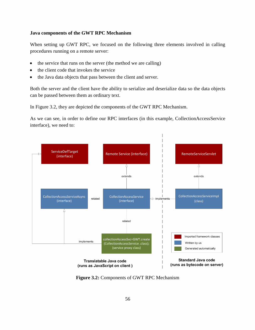
56
Java components of the GWT RPC Mechanism
When setting up GWT RPC, we focused on the following three elements involved in calling
procedures running on a remote server:
the service that runs on the server (the method we are calling)
the client code that invokes the service
the Java data objects that pass between the client and server.
Both the server and the client have the ability to serialize and deserialize data so the data objects
can be passed between them as ordinary text.
In Figure 3.2, they are depicted the components of the GWT RPC Mechanism.
As we can see, in order to define our RPC interfaces (in this example, CollectionAccessService
interface), we need to:
Figure 3.2: Components of GWT RPC Mechanism
57
1. Define an interface (CollectionAccessService) for our service that extends RemoteService
interface and lists all our RPC methods.
2. Define a class (CollectionAccessServiceImpl) to implement the server-side code that extends
RemoteServiceServlet and implements the interface we created above.
3. Define an asynchronous interface (CollectionAccessServiceAsync) to our service to be called
from the client-side code.
The nature of asynchronous method calls requires the caller to pass in a callback object that can
be notified when an asynchronous call completes, since by definition the caller cannot be
blocked until the call completes. For the same reason, asynchronous methods do not have return
types; they generally return void. After an asynchronous call is made, all communication back to
the caller is via the passed-in callback object.
The name convention that is adopted for our services is:
The interface for each service that lists all its RPC methods is named as
ServiceNameService.
The class that implements the server-side code and implements the previous interface is
named as ServiceNameServiceImpl.
Finally, the asynchronous interface to the service that is called from client-side is named as
ServiceNameServiceAsync.
58
Chapter 4
4 Implementation of the Model based on RDF
and SPARQL
In this Chapter, we discuss the implementation of the model based on RDF and SPARQL. We
first provide an overview of the implementation of the model by relational database technologies
as well as by RDF and SPARQL technologies. We then discuss the implementation of the model
by translating the model into RDF; following this we map the query language for digital libraries
to SPARQL.
This Chapter is organized as follows. Section 4.1 considers implementing the model by relational
database technologies as well as by RDF and SPARQL technologies. Section 4.2 defines the
translation from our model to RDF, as described in Figure 4.1. In particular, Section 4.2.1
defines the function for translating an interpretation I into an RDFDL graph; Section 4.2.2
gives the semantics of RDFDL, on top of which the inference mechanism R on RDFDL graphs
is defined; Section 4.2.3 discusses the computation issues. Subsequently, Section 4.3 defines the
translation from our query language for digital libraries to SPARQL. In particular, Section 4.3.1
extends the function to translate the variables in L to SPARQL variables; Section 4.3.2 defines
the function to translate Q queries to SPARQL queries; and Section 4.3.3 proves the
correctness of the mapping from Q to SPARQL.
4.1 Implementing the Model
So far, we have adopted a logical approach for modeling a digital library. This choice was
deliberate in order to be able to express the basic concepts of digital libraries without being
constrained by any technical considerations. However, the goal of our work is to contribute to
the technology of digital libraries. Therefore, we now consider how the model can be
implemented. We recall that a digital library consists of two parts, the reference table and the
metadata base.
Regarding the implementation of the reference table, we remark that its maintenance is typically
handled by the operating system, and in particular by the file system. Therefore, we shall not
consider the maintenance of the reference table any further. Rather, we focus our attention to the
implementation of the metadata base, and we consider two different scenarios.
59
The first scenario consists in implementing the metadata base as a relational database and
computing the completion of a digital library via a datalog engine [52][53][54]. Querying
can be implemented by mapping our query language to SQL, and executing the resulting
queries over the relational database. This implementation is conceptually straightforward
(as the metadata base is in fact a relational database).
The second scenario consists in implementing the metadata base as an RDF graph, and
using an RDF inference engine for computing the completion of the digital library.
Querying can be implemented by mapping our query language to SPARQL [37]. This
implementation is conceptually much more demanding, as it requires translating the
relations and the axioms of our model in RDF.
The first scenario exploits the well-established relational technology, including the optimized
query processing of SQL. This guarantees scalability and robustness of the implementation. The
second scenario benefits from the fact that RDF is a generally accepted representation language
in the context of digital libraries and the Semantic Web. Although RDF has not yet achieved the
maturity of relational technology, tools for managing RDF graphs have been intensely
researched and developed in the last decade, and are now reaching a significant level of
technological maturity1. Such tools include systems for the persistence of large RDF graphs in
secondary storage (so called triple stores), RDF inference engines and optimized query
processing engines for SPARQL2.
Choosing one between these two scenarios depends on contextual factors. As we have already
observed, translating from the model to relational is straightforward, while translating from the
model to RDF is more demanding. However, in this thesis we choose the second scenario
because of the ability to provide interoperability between applications of RDF and the ability to
enable automated processing of Web resources of it.
For this reason, in the rest of this Chapter we focus on translation based on the second scenario,
and we provide an injective mapping from the model to RDF.
4.2 Mapping to RDF
RDF is a knowledge representation language for describing resources using triples of the form
(subject, predicate, object). In a triple, the subject can be a URI or a local identifier (also called
blank node) for unnamed entities; the predicate can only be a URI; the object can be a URI, a
local identifier or a literal (i.e. a string of characters). The predicate in an RDF triple specifies
how the subject and the object of the triple are related.
1 See, for instance: www.w3.org/2001/sw/wiki/Tools
2 e.g. esw.w3.org/SparqlImplementations
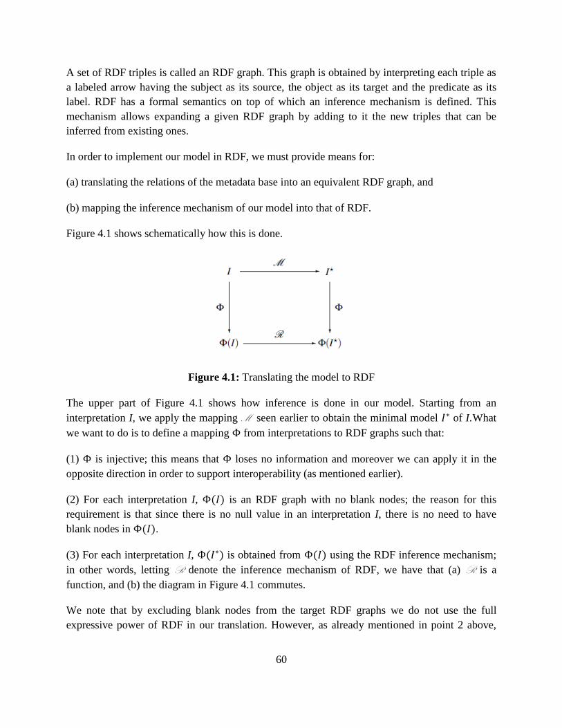
60
A set of RDF triples is called an RDF graph. This graph is obtained by interpreting each triple as
a labeled arrow having the subject as its source, the object as its target and the predicate as its
label. RDF has a formal semantics on top of which an inference mechanism is defined. This
mechanism allows expanding a given RDF graph by adding to it the new triples that can be
inferred from existing ones.
In order to implement our model in RDF, we must provide means for:
(a) translating the relations of the metadata base into an equivalent RDF graph, and
(b) mapping the inference mechanism of our model into that of RDF.
Figure 4.1 shows schematically how this is done.
Figure 4.1: Translating the model to RDF
The upper part of Figure 4.1 shows how inference is done in our model. Starting from an
interpretation I, we apply the mapping M seen earlier to obtain the minimal model of I. What
we want to do is to define a mapping from interpretations to RDF graphs such that:
(1) is injective; this means that loses no information and moreover we can apply it in the
opposite direction in order to support interoperability (as mentioned earlier).
(2) For each interpretation I, ( ) is an RDF graph with no blank nodes; the reason for this
requirement is that since there is no null value in an interpretation I, there is no need to have
blank nodes in ( ).
(3) For each interpretation I, ( ) is obtained from ( ) using the RDF inference mechanism;
in other words, letting R denote the inference mechanism of RDF, we have that (a) R is a
function, and (b) the diagram in Figure 4.1 commutes.
We note that by excluding blank nodes from the target RDF graphs we do not use the full
expressive power of RDF in our translation. However, as already mentioned in point 2 above,
61
this expressive power is not needed to implement our model as interpretations in our model do
not contain null values.
4.2.1 The Function
We now define the translation from our model to RDF, as described in Figure 4.1. In particular,
we define the function . In order to do so, we need to define the RDF vocabulary of the range of
. We shall denote this vocabulary as RDFDL. RDFDL will be defined as the union of two
vocabularies:
(1) a subset of the RDFS vocabulary, called [55], required to translate the schema relation
names, namely: Dom, Ran, IsaCl, IsaPr, ClInst; and
(2) a new vocabulary, including the URIs for translating those relation names that have no
corresponding property in RDFS, namely: DescCl, DescPr, DescOf, and PartOf. The relation
names SchCl and SchPr, will be directly translated into URIs, while the translation of tuples in
relation PrInst does not require any additional RDF property.
Function will be defined to translate each tuple in the metadata base into one or more RDF
triples. To do this we need:
(a) an auxiliary function that translates identifiers to URIs; and
(b) a mapping from tuples to triples that uses the auxiliary function on identifiers.
These two functions are defined in separate sections, below.
4.2.1.1 Translating Identifiers to URI References
As already pointed out, RDF supports three kinds of terms [36]: URI references, literals and
blank nodes. URI references (abbreviated as URIrefs [41]) are unique resource identifiers, thus
they naturally correspond to the identifiers of our model. We will therefore translate identifiers
of our model as URIrefs. In so doing, we will also adhere to the recommendations of Linked
Data3.
First, we assume a special namespace for the URIrefs resulting from the translation of identifiers.
We shall call this namespace N, without entering in the details of its actual syntax.
The translation is trivial if no URIref is used as an identifier in an interpretation I; one simply
maps identifiers of I to URIrefs in the namespace N in an injective manner. However, users may
3 www4.wiwiss.fu-berlin.de/bizer/pub/LinkedDataTutorial/
62
want to re-use URIrefs from existing namespaces as identifiers in the metadata base for
interoperability reasons. We leave this freedom to the user, but we require the user to respect the
following three constraints that guarantee the injectivity of the translation, we shall call these the
id constraints:
(1) No URIref in the RDFDL namespace can be used as an identifier in the metadata base;
(2) If a URIref is used as a schema identifier in the metadata base, then it must be a
syntactically valid URIref terminating with the sharp symbol ―#‖. Moreover, if a URIref
is used as a class or property identifier in the metadata base, then it must be a fragment
identifier [41]. This constraint will guarantee that in the RDF translation of an
interpretation, we can compose schema identifiers with the identifiers of classes or
properties. We note that since a URIref can contain at most one sharp symbol, we can
recover from such a URIref the original schema and class (or property) identifiers.
(3) If a URIref s is used as a schema identifier in the metadata base and a URIref is used as
class or property identifier, then their concatenation (:) is not in the metadata base,
namely:
Technically, the translation of metadata base identifiers to URIrefs is carried out by the functions
, , , , and , whose definitions rely on the following auxiliary functions , , ,
and :
is an injective function that translates a given non-URIref schema identifier to a
URIref with suffix ―#‖ in the namespace N;
is an injective function that translates a given non-fragment class or property identifier
to a fragment identifier in the namespace N;
is an injective function that translates a given non-URIref description identifier to a
URIref in the namespace N;
is an injective function that translates a given non-URIref composable resource
identifier into a URIref in the namespace N.
Injectivity requires not to generate the same URIref from two different identifiers in the metadata
base. This can be realized in several ways, for instance by incrementing a counter. However, we
shall not enter into technical details here.
Based on the above functions, we now define the functions , , , , as follows:
{
( )
63
{
( )
{
( )
{
( )
What each of these functions essentially does is to generate a correct URIref from the input
identifier if this identifier is not already a (correct) URIref. By their definition, these functions
are injective because the auxiliary functions are injective.
We note that, sharp (#) is not universally used in the URI of existing vocabularies, for instance,
the URI of the class ―Bird‖ in DBPedia is http://dbpedia.org/ontology/Bird. As a consequence,
http://dbpedia.org/ontology/Bird will be mapped to a different URI in the namespace N by
function . This is not ideal; however, it is important to note that there is no universally
accepted convention for naming resources in RDF (apart from the rules of the URI syntax),
therefore this kind of mismatch will occur for certain classes of URIs, no matter what convention
we rely upon for the translation in RDF. What is important is that the formal properties of the
translation are not broken.
Finally, for convenience of notation, we define a generic function that, given an input identifier
i, applies to i one of the translation functions defined above depending on the type of i:
{
Notice that the above function is injective, as a consequence of the injectivity of its defining
functions.
4.2.1.2 Translating Metadata Base Tuples into RDF Triples
A basic decision that must be taken in order to map an interpretation into an RDF graph,
concerns the target RDF vocabulary, that is the set of RDF classes and properties that will appear
in the RDF graph resulting from the translation. For generality, we aim at a minimal vocabulary
that re-uses as much as possible the existing RDF vocabularies. As it turns out, our model can be
translated into a fragment of the RDFS vocabulary [56], with the addition of just three properties.
Quoting [56], ―RDFS vocabulary, also called RDF Schema, is a semantic extension (as defined
in [57]) of RDF. It provides mechanisms for describing groups of related resources and the
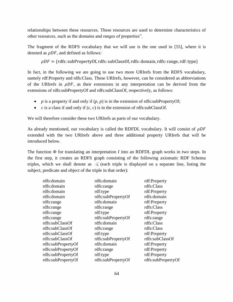
64
relationships between these resources. These resources are used to determine characteristics of
other resources, such as the domains and ranges of properties‖.
The fragment of the RDFS vocabulary that we will use is the one used in [55], where it is
denoted as , and defined as follows:
* +
In fact, in the following we are going to use two more URIrefs from the RDFS vocabulary,
namely rdf:Property and rdfs:Class. These URIrefs, however, can be considered as abbreviations
of the URIrefs in , as their extensions in any interpretation can be derived from the
extensions of rdfs:subPropertyOf and rdfs:subClassOf, respectively, as follows:
p is a property if and only if (p, p) is in the extension of rdfs:subPropertyOf;
c is a class if and only if (c, c) is in the extension of rdfs:subClassOf.
We will therefore consider these two URIrefs as parts of our vocabulary.
As already mentioned, our vocabulary is called the RDFDL vocabulary. It will consist of
extended with the two URIrefs above and three additional property URIrefs that will be
introduced below.
The function for translating an interpretation I into an RDFDL graph works in two steps. In
the first step, it creates an RDFS graph consisting of the following axiomatic RDF Schema
triples, which we shall denote as TS (each triple is displayed on a separate line, listing the
subject, predicate and object of the triple in that order):
rdfs:domain
rdfs:domain
rdfs:domain
rdfs:domain
rdfs:range
rdfs:range
rdfs:range
rdfs:range
rdfs:subClassOf
rdfs:subClassOf
rdfs:subClassOf
rdfs:subClassOf
rdfs:subPropertyOf
rdfs:subPropertyOf
rdfs:subPropertyOf
rdfs:subPropertyOf
rdfs:domain
rdfs:range
rdf:type
rdfs:subPropertyOf
rdfs:domain
rdfs:range
rdf:type
rdfs:subPropertyOf
rdfs:domain
rdfs:range
rdf:type
rdfs:subPropertyOf
rdfs:domain
rdfs:range
rdf:type
rdfs:subPropertyOf
rdf:Property
rdfs:Class
rdf:Property
rdfs:domain
rdf:Property
rdfs:Class
rdf:Property
rdfs:range
rdfs:Class
rdfs:Class
rdf:Property
rdfs:subClassOf
rdf:Property
rdf:Property
rdf:Property
rdfs:subPropertyOf
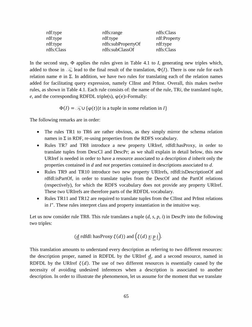
65
rdf:type
rdf:type
rdf:type
rdfs:Class
rdfs:range
rdf:type
rdfs:subPropertyOf
rdfs:subClassOf
rdfs:Class
rdf:Property
rdf:type
rdfs:Class
In the second step, applies the rules given in Table 4.1 to I, generating new triples which,
added to those in TS, lead to the final result of the translation, ( ). There is one rule for each
relation name in . In addition, we have two rules for translating each of the relation names
added for facilitating query expression, namely ClInst and PrInst. Overall, this makes twelve
rules, as shown in Table 4.1. Each rule consists of: the name of the rule, TRi, the translated tuple,
e, and the corresponding RDFDL triple(s), ( ). Formally:
( ) TS * ( ) +
The following remarks are in order:
The rules TR1 to TR6 are rather obvious, as they simply mirror the schema relation
names in in RDF, re-using properties from the RDFS vocabulary.
Rules TR7 and TR8 introduce a new property URIref, rdfdl:hasProxy, in order to
translate tuples from DescCl and DescPr; as we shall explain in detail below, this new
URIref is needed in order to have a resource associated to a description d inherit only the
properties contained in d and not properties contained in descriptions associated to d.
Rules TR9 and TR10 introduce two new property URIrefs, rdfdl:isDescriptionOf and
rdfdl:isPartOf, in order to translate tuples from the DescOf and the PartOf relations
(respectively), for which the RDFS vocabulary does not provide any property URIref.
These two URIrefs are therefore parts of the RDFDL vocabulary.
Rules TR11 and TR12 are required to translate tuples from the ClInst and PrInst relations
in . These rules interpret class and property instantiation in the intuitive way.
Let us now consider rule TR8. This rule translates a tuple (d, s, p, i) in DescPr into the following
two triples:
( ( )) and . ( ) /
This translation amounts to understand every description as referring to two different resources:
the description proper, named in RDFDL by the URIref , and a second resource, named in
RDFDL by the URIref ( ). The use of two different resources is essentially caused by the
necessity of avoiding undesired inferences when a description is associated to another
description. In order to illustrate the phenomenon, let us assume for the moment that we translate
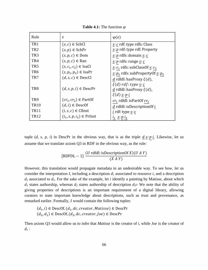
66
Table 4.1: The function
Rule e ( )
TR1
TR2
TR3
TR4
TR5
TR6
TR7
TR8
TR9
TR10
TR11
TR12
( )
( )
( )
( )
( )
( )
( )
( )
( )
( )
( )
( )
( ),
( )
( ),
( )
tuple (d, s, p, i) in DescPr in the obvious way, that is as the triple . Likewise, let us
assume that we translate axiom Q3 in RDF in the obvious way, as the rule:
, - ( )( )
( )
However, this translation would propagate metadata in an undesirable way. To see how, let us
consider the interpretation I, including a description d1 associated to resource i, and a description
d2 associated to d1. For the sake of the example, let i identify a painting by Matisse, about which
d1 states authorship, whereas d2 states authorship of description d1. We note that the ability of
giving properties of descriptions is an important requirement of a digital library, allowing
curators to state important knowledge about descriptions, such as trust and provenance, as
remarked earlier. Formally, I would contain the following tuples:
( ) ( )
( ) ( )
Then axiom Q3 would allow us to infer that Matisse is the creator of i, while Joe is the creator of
d1 :
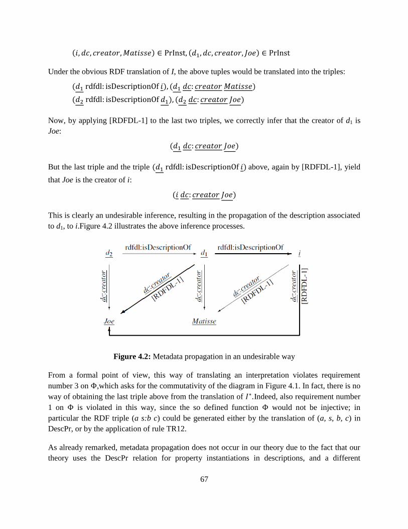
67
( ) ( )
Under the obvious RDF translation of I, the above tuples would be translated into the triples:
( ) ( )
( ) ( )
Now, by applying [RDFDL-1] to the last two triples, we correctly infer that the creator of d1 is
Joe:
( )
But the last triple and the triple ( ) above, again by [RDFDL-1], yield
that Joe is the creator of i:
( )
This is clearly an undesirable inference, resulting in the propagation of the description associated
to d1, to i. Figure 4.2 illustrates the above inference processes.
Figure 4.2: Metadata propagation in an undesirable way
From a formal point of view, this way of translating an interpretation violates requirement
number 3 on , which asks for the commutativity of the diagram in Figure 4.1. In fact, there is no
way of obtaining the last triple above from the translation of . Indeed, also requirement number
1 on is violated in this way, since the so defined function would not be injective; in
particular the RDF triple (a s:b c) could be generated either by the translation of (a, s, b, c) in
DescPr, or by the application of rule TR12.
As already remarked, metadata propagation does not occur in our theory due to the fact that our
theory uses the DescPr relation for property instantiations in descriptions, and a different
68
relation, PrInst, to represent properties of resources. These relations are of arity 4 and 3,
respectively, and are not immediately translatable into RDF, which is essentially a logic of
binary predicate symbols. In order to enforce the same distinction in the RDF translation of our
model, we therefore mark the triples resulting from translating DescPr tuples by using special
URIrefs as subjects. Each one of these URIrefs is obtained by applying a function to the
involved description identifier d, and it is denoted in our model as ( ). d and ( ) are related by
the rdfdl:hasProxy property. This explains rule TR8. The explanation of rule TR7 follows by a
similar argument.
It is natural to ask what kind of resource ( ) identifies. A possible answer is that ( ) identifies
a resource (any resource) to which d can be associated. An individual of this kind is sometimes
called a ―prototype‖, or a ―proxy‖, namely someone standing for someone else in a specific
context4. We adhere to the latter terminology, and denote the property relating d and ( ) as
rdfdl:hasProxy. In order to carry out its duty, must satisfy the following conditions:
is a total function over the set IDd of all description identifiers occurring in I;
the range of function is a set of URIrefs disjoint from the URIrefs occurring in ( ),
namely for any description identifier d and any composable resource identifier cr, schema
identifier s, or fragment identifier in I:
( ) , ( ) ( )
is an injective function, that is for any two description identifiers d1 and d2:
implies ( ) ( )
From a practical point of view, ( ) might be a URIref allowing to recover d by a simple string
manipulation.
Overall, the RDFDL vocabulary consists of:
(a) the vocabulary extended with the rdf:Property and rdfs:Class URIrefs, and
(b) the following URIrefs:
rdfdl:isPartOf, which is a property URIref, required to translate PartOf statements;
rdfdl:isDescriptionOf, which is a property URIref, required to translate DescOf
statements;
rdfdl:hasProxy, which is a property URIref, required to translate DescPr statements.
4 This terminology is adopted in the OAI-ORE model.
69
We observe that the Dublin Core Metadata Initiative (DCMI) [46] offers the term isPartOf that
can be equated with PartOf. Moreover, rdfdl:isDescriptionOf is somewhat similar to the
describes property in the OAI-ORE [58] vocabulary, which relates a resource map to the
aggregation that the map describes. Finally, rdfdl:hasProxy is somewhat similar to the hasProxy
property in the OAI-ORE vocabulary, which relates a resource to a representative of it, in the
context of a specific aggregation. Despite these terminological similarities, the terms in the
RDFDL namespace obey axioms that are not necessarily applicable to the related properties in
the DCMI or OAI-ORE namespaces, and for this reason we think it is appropriate to keep our
terms separated.
4.2.2 The Function R
We now give the semantics of RDFDL, on top of which we will define the inference mechanism
R on RDFDL graphs.
The function R carries out the inference on the graphs resulting from the translation of
interpretations. Such graphs are expressed in the RDFDL vocabulary, therefore in order to define
R we must give the semantics of the RDFDL vocabulary. Such semantics is based on the notion
of RDFDL-interpretation, defined next.
An RDFDL-interpretation is an rdfs-interpretation that satisfies:
the following axiomatic RDFDL triples (whose set will be denoted as TDL):
rdfdl:isPartOf rdf:type rdf:Property
rdfdl:isDescriptionOf rdf:type rdf:Property
rdfdl:hasProxy rdf:type rdf:Property
and the following semantic conditions:
- (SC-1): ⟨ ⟩ ( ( )) ⟨ ⟩
( ( )) ⟨ ⟩ ( ( )) ⟨ ⟩ ( ( ))
- (SC-2): ⟨ ⟩ ( ( )) ⟨ ⟩
( ( )) ⟨ ⟩ ( ( ))
The semantic conditions allow us to capture the inferences licensed by our theory that are not
captured by the inference mechanism of RDFS. In particular:
The first semantic condition above transfers the features of descriptions to the resources
the descriptions are about. It therefore licenses the following two inferences:
70
- *( ) ( ) ( )+ rdfdl-entails ( ) by
application of the above semantic condition with the following binding: ,
, , and . This inference is licensed in our theory by axiom Q3.
- *( ) ( ) ( )+ rdfdl-entails
( ) by application of the first RDFS semantic condition and the above
semantic condition with the following binding: , , ,
and . This inference is licensed in our theory by axiom Q1.
The second semantic condition captures axiom D2, which transfers to composite
resources the metadata of their parts.
Given any two graphs S and S’ over the RDFDL vocabulary, S RDFDL-entails S’, in symbols
, iff every RDFDL-interpretation that satisfies S also satisfies S’.
Next, we need to derive a calculus for implementing RDFDL-entailment. The original calculus
defined in [57] suffers from incompleteness, in that it does not capture rdfs-entailments involving
properties that are blank nodes [59]. A calculus that does not suffer from this problem is
presented in [55]. Since in the present context blank nodes are excluded from the source RDF
graph, the incompleteness in the original RDF calculus will never arise. The original calculus of
the RDF semantics is complex and makes the proof of injectivity of the function very long and
difficult to grasp. We therefore opt for the calculus in [55], which avoids the complexities of the
original RDFS specification, and captures the normative semantics and the core functionalities of
RDFS. To this end, we need to express RDFDL-entailment in terms of the rule-based calculus in
[55]. This requires the definition of the rules (RDFDL-1) and (RDFDL-2), given by Table 4.2.
Table 4.2: The deductive rules of RDFDL
, - ( )( ) ( )
( )
, - ( )( )
( )
Definition 8. Let G and H be RDFDL-graphs. We define iff there exists a sequence
of graphs P1, P2,…, Pk, with P1 = G and Pk = H, and for each j( ) one of the following
cases hold:
- (rule(1b)),
- there is an instantiation
of one of the rules (2)-(7), (RDFDL-1) and (RDFDL-2),
such that and .
71
Whenever holds, we say that the graph G derives the graph H (or H is derived by
G).
Theorem 1. Let G and H be RDFDL-graphs. Then
iff .
Proof. See [32].
Theorem 1 is sufficient to define R and show that it is indeed a function. In fact, from Table 4.1,
it can be seen that the range of does not include any blank node; since both the domain and the
range of R (represented by ( ) and ( ) in Figure 4.1, respectively) are in the range of , in
computing RDFDL-entailment we can disregard the rules that have triples including blank nodes
either as input or as output. This leaves us with rules (1b), (2)-(7) of the deductive rules [55]
together with the rules (RDFDL-1) and (RDFDL-2). Since all these rules are deterministic and
guaranteed to terminate (as they only add arcs to the initial graph), we have that ( ) is unique
and therefore R is a function.
So far, we have defined the functions and R . In Section 4.2 we have set three requirements
that these two functions must satisfy: (1) that must be injective, (2) that they do not generate
RDFDL graphs with blank nodes, and (3) that R is a function and the diagram in Figure 4.1
commutes. We have already shown (2) and the first part of (3). What remains to be shown is
injectivity of and commutativity of the diagram in Figure 4.1. Both these proofs are given in
the appendix of [32].
4.2.3 Computational Issues
Now let us consider the complexity of the RDF implementation of the model, by analyzing the
complexity of deriving ( ) from a given interpretation I.
From Table 4.1, it is easy to see that: given one tuple from I, can generate at most two triples
by rule TR7 or TR8. Assuming as constant the time to apply one transformation rule, we have
that the RDFDL graph ( ) can be generated in polynomial time and its size is of the same order
of magnitude as the size of I. From the efficiency of our model, we then have the efficiency of its
RDF translation.
4.3 Translation from Q to SPARQL
In order to translate Q queries into SPARQL [37], we now define a function that takes as
input any query in Q and returns an equivalent SPARQL query.
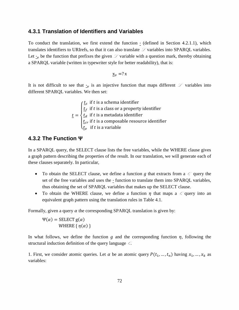
72
4.3.1 Translation of Identifiers and Variables
To conduct the translation, we first extend the function (defined in Section 4.2.1.1), which
translates identifiers to URIrefs, so that it can also translate L variables into SPARQL variables.
Let be the function that prefixes the given L variable with a question mark, thereby obtaining
a SPARQL variable (written in typewriter style for better readability), that is:
It is not difficult to see that is an injective function that maps different L variables into
different SPARQL variables. We then set:
{
4.3.2 The Function
In a SPARQL query, the SELECT clause lists the free variables, while the WHERE clause gives
a graph pattern describing the properties of the result. In our translation, we will generate each of
these clauses separately. In particular,
To obtain the SELECT clause, we define a function g that extracts from a Q query the
set of the free variables and uses the function to translate them into SPARQL variables,
thus obtaining the set of SPARQL variables that makes up the SELECT clause.
To obtain the WHERE clause, we define a function that maps a Q query into an
equivalent graph pattern using the translation rules in Table 4.1.
Formally, given a query the corresponding SPARQL translation is given by:
( ) ( )
* ( ) +
In what follows, we define the function g and the corresponding function , following the
structural induction definition of the query language Q.
1. First, we consider atomic queries. Let be an atomic query ( ) having as
variables:
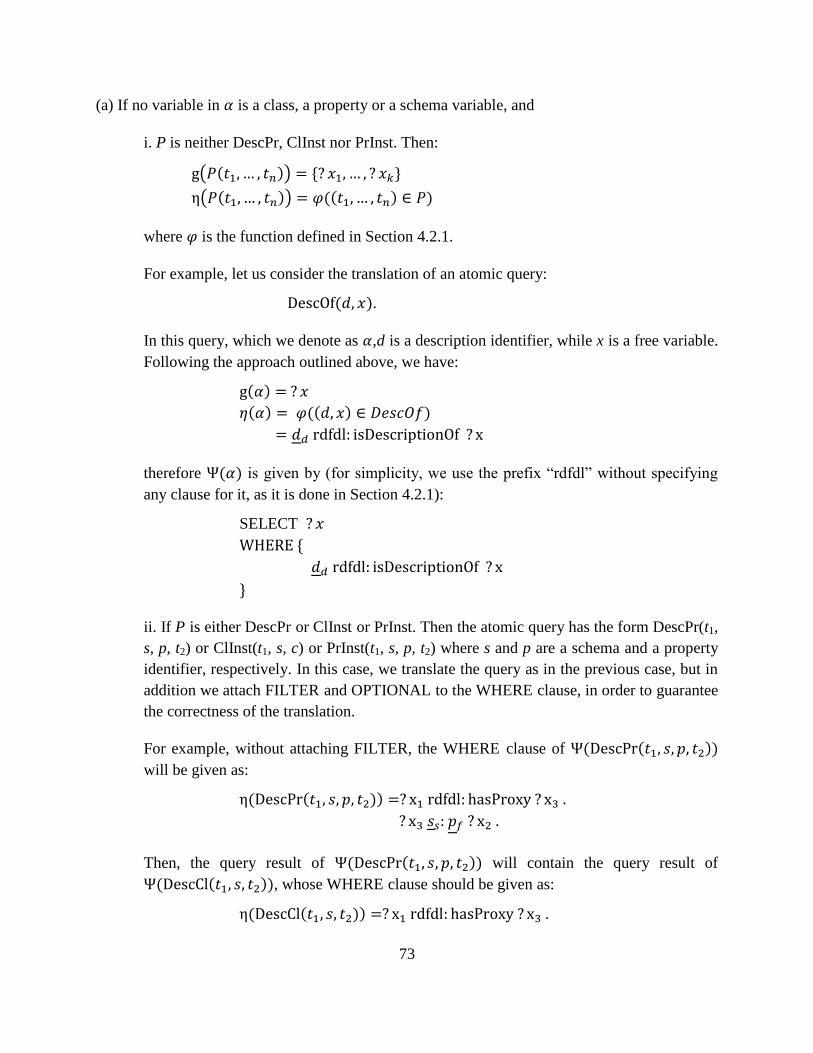
73
(a) If no variable in is a class, a property or a schema variable, and
i. P is neither DescPr, ClInst nor PrInst. Then:
( ( )) * +
( ( )) (( ) )
where is the function defined in Section 4.2.1.
For example, let us consider the translation of an atomic query:
( ).
In this query, which we denote as , d is a description identifier, while x is a free variable.
Following the approach outlined above, we have:
( )
( ) (( ) )
therefore ( ) is given by (for simplicity, we use the prefix ―rdfdl‖ without specifying
any clause for it, as it is done in Section 4.2.1):
SELECT
*
+
ii. If P is either DescPr or ClInst or PrInst. Then the atomic query has the form DescPr(t1,
s, p, t2) or ClInst(t1, s, c) or PrInst(t1, s, p, t2) where s and p are a schema and a property
identifier, respectively. In this case, we translate the query as in the previous case, but in
addition we attach FILTER and OPTIONAL to the WHERE clause, in order to guarantee
the correctness of the translation.
For example, without attaching FILTER, the WHERE clause of ( ( ))
will be given as:
( ( ))
Then, the query result of ( ( )) will contain the query result of
( ( )), whose WHERE clause should be given as:
( ( ))
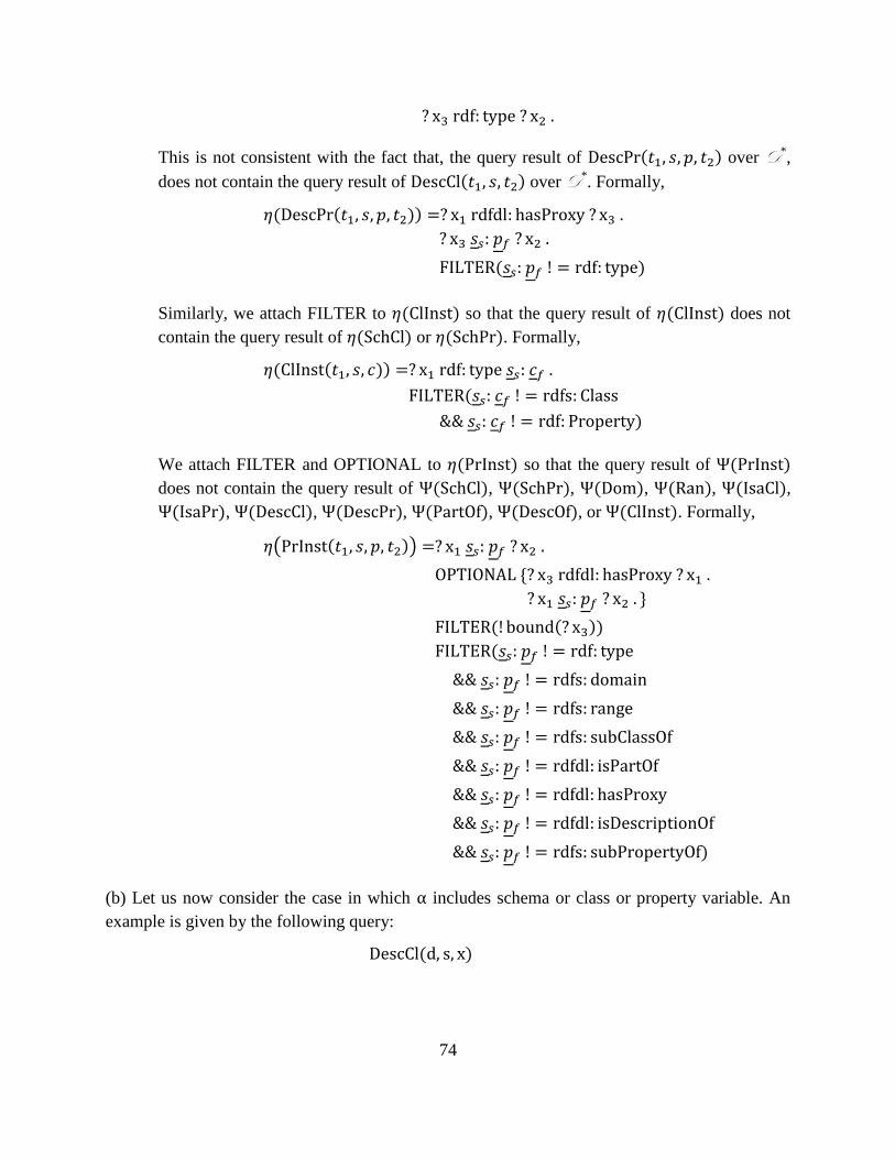
74
This is not consistent with the fact that, the query result of ( ) over D*,
does not contain the query result of ( ) over D*. Formally,
( ( ))
( )
Similarly, we attach FILTER to ( ) so that the query result of ( ) does not
contain the query result of ( ) or ( ). Formally,
( ( ))
(
)
We attach FILTER and OPTIONAL to ( ) so that the query result of ( )
does not contain the query result of ( ), ( ), ( ), ( ), ( ),
( ), ( ), ( ), ( ), ( ), or ( ). Formally,
( ( ))
*
+
( ( ))
(
)
(b) Let us now consider the case in which includes schema or class or property variable. An
example is given by the following query:
( )
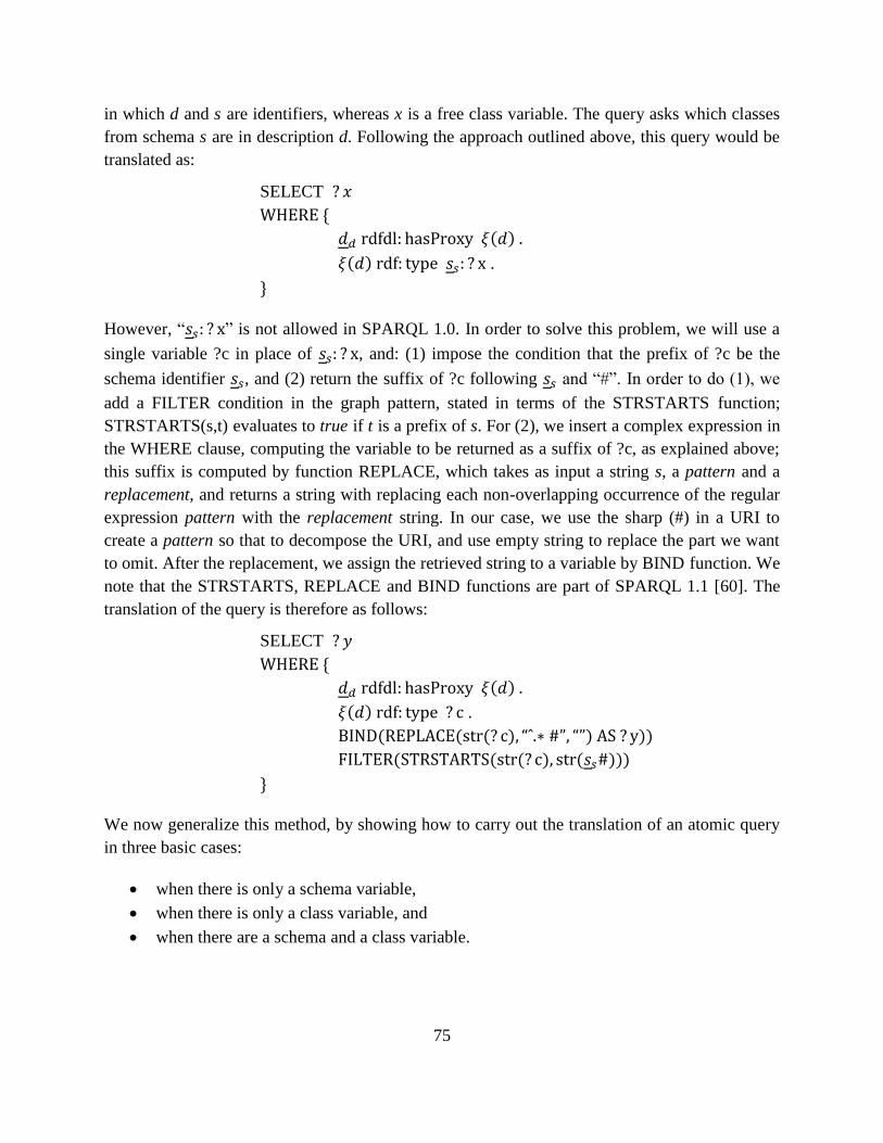
75
in which d and s are identifiers, whereas x is a free class variable. The query asks which classes
from schema s are in description d. Following the approach outlined above, this query would be
translated as:
SELECT
*
( )
( ) .
+
However, ― ‖ is not allowed in SPARQL 1.0. In order to solve this problem, we will use a
single variable ?c in place of , and: (1) impose the condition that the prefix of ?c be the
schema identifier , and (2) return the suffix of ?c following and ―#‖. In order to do (1), we
add a FILTER condition in the graph pattern, stated in terms of the STRSTARTS function;
STRSTARTS(s,t) evaluates to true if t is a prefix of s. For (2), we insert a complex expression in
the WHERE clause, computing the variable to be returned as a suffix of ?c, as explained above;
this suffix is computed by function REPLACE, which takes as input a string s, a pattern and a
replacement, and returns a string with replacing each non-overlapping occurrence of the regular
expression pattern with the replacement string. In our case, we use the sharp (#) in a URI to
create a pattern so that to decompose the URI, and use empty string to replace the part we want
to omit. After the replacement, we assign the retrieved string to a variable by BIND function. We
note that the STRSTARTS, REPLACE and BIND functions are part of SPARQL 1.1 [60]. The
translation of the query is therefore as follows:
SELECT
*
( )
( ) .
( ( ( ) ) ))
( ( ( ) ( )))
+
We now generalize this method, by showing how to carry out the translation of an atomic query
in three basic cases:
when there is only a schema variable,
when there is only a class variable, and
when there are a schema and a class variable.

76
Any other case can be derived from these three cases, by combining them in the obvious way.
We assume (with no loss of generality) that t1 is a schema identifier or variable, t2 represents a
fragment (class or property) identifier or a variable, and that ?u is the concatenation of t1 and t2,
namely
.
Case 1, if ( ) includes only a schema variable t1, it is translated as:
( ( ))
( ( )) (( ) )
( ( ( ) ) ))
( ( ( ) ( )))
Case 2, if ( ) includes only a class variable t2, it is translated as:
( ( ))
( ( )) (( ) )
( ( ( ) ) ))
( ( ( ) ( )))
Case 3, if ( ) includes only a schema variable t1 and a class variable t2, it is
translated as:
( ( ))
( ( )) (( ) )
( ( ( ) ) ))
( ( ( ) ) ))
For example, let us consider an atomic query:
( )
in which d is an identifier, x1 is a schema variable and x2 is a class variable. We assume
, then, ( ) is given by:
*
( )
( ) .
( ( ( ) ) ))
( ( ( ) ) ))
}
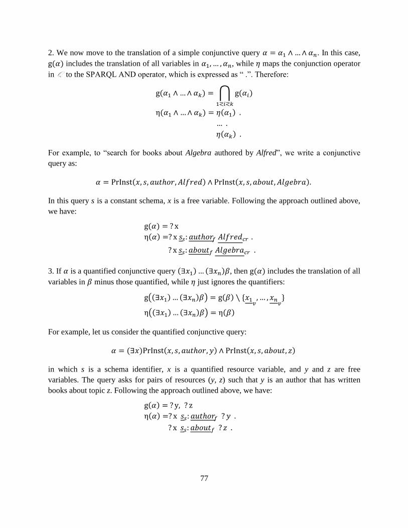
77
2. We now move to the translation of a simple conjunctive query . In this case,
( ) includes the translation of all variables in , while maps the conjunction operator
in Q to the SPARQL AND operator, which is expressed as ― .‖. Therefore:
( ) ⋂ ( )
( ) ( )
( )
For example, to ―search for books about Algebra authored by Alfred‖, we write a conjunctive
query as:
( ) ( )
In this query s is a constant schema, x is a free variable. Following the approach outlined above,
we have:
( )
( )
3. If is a quantified conjunctive query ( ) ( ) , then ( ) includes the translation of all
variables in minus those quantified, while just ignores the quantifiers:
(( ) ( ) ) ( ) *
+
(( ) ( ) ) ( )
For example, let us consider the quantified conjunctive query:
( ) ( ) ( )
in which s is a schema identifier, x is a quantified resource variable, and y and z are free
variables. The query asks for pairs of resources (y, z) such that y is an author that has written
books about topic z. Following the approach outlined above, we have:
( )
( )
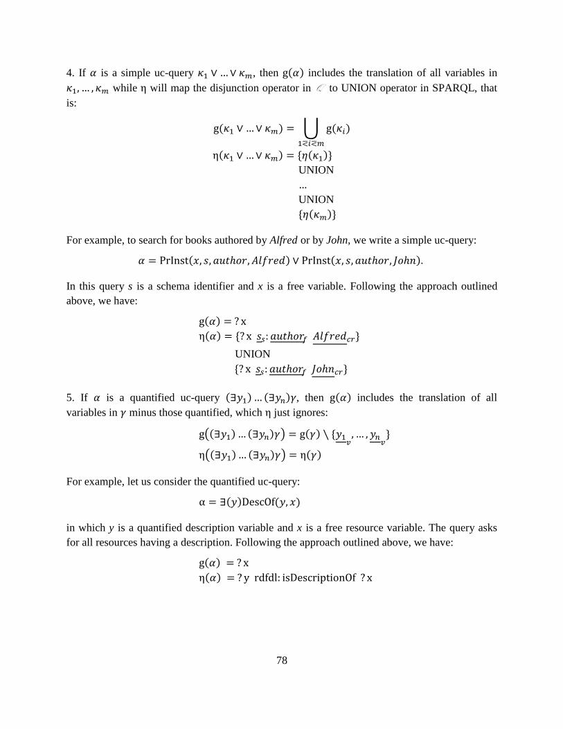
78
4. If is a simple uc-query , then ( ) includes the translation of all variables in
while will map the disjunction operator in Q to UNION operator in SPARQL, that
is:
( ) ⋃ ( )
( ) * ( )+
UNION
UNION
* ( )+
For example, to search for books authored by Alfred or by John, we write a simple uc-query:
( ) ( )
In this query s is a schema identifier and x is a free variable. Following the approach outlined
above, we have:
( )
( ) * +
UNION
* +
5. If is a quantified uc-query ( ) ( ) , then ( ) includes the translation of all
variables in minus those quantified, which just ignores:
(( ) ( ) ) ( ) *
+
(( ) ( ) ) ( )
For example, let us consider the quantified uc-query:
( ) ( )
in which y is a quantified description variable and x is a free resource variable. The query asks
for all resources having a description. Following the approach outlined above, we have:
( )
( )
79
4.3.3 Correctness
While the semantics of full SPARQL is still under study [61], the fragment that we cover with
the translation of Q , is totally unproblematic. This allows us to prove the equivalence between a
query in Q and the corresponding ( ). To this end, we first extend function to translate a
query result in our model (given as a set of tuples over identifiers) to a query result in SPARQL
(given as a set of mappings), as follows:
( ( ( ) D )) *⟨ ⟩
⟨ ⟩ ( ( ) D )+
The translation is clearly straightforward, it just makes explicit the correspondence between the
free variables in the query and the identifiers in the result that in Definition 7 is captured by
substitutions. This guarantees that the so extended is injective. Notice that for readability, in
the above definition we write in place of the formally more correct .
Figure 4.3 shows how the equivalence between a query in Q and the corresponding SPARQL
query ( ) is to be proved. The higher part of this figure illustrates how querying in our model
works: a user asking a query to a digital library D ( ) gets as an answer the set of
tuples ( D). By definition of the ans function, the same answer is obtained if the query is
asked to the completion of D, D*, having as metadata base. In other words,
( D) ( D*)
for every Q query and digital library D . The lower part of the diagram shows how querying
can be implemented in RDF. In this case, however, the translation of the query ( ) must be
asked directly to ( ), because by definition SPARQL does not do any inference, it only
extracts from a given graph the information specified by the SPARQL query. The equivalence of
the two mechanisms is then to be proved by the commutativity of the diagram.
In Section 4.2, we have already proved the equivalence between the inference mechanism of our
model and that of RDF, by showing the commutativity of the left part of the diagram in Figure
4.3. In this section, we carry out the proof for the right part of the diagram, namely we show that
the translation to RDF of the answer to a Q query asked to a complete digital library D*,
having as metadata base, equals the answer to the SPARQL query ( ) asked to the
translation of . Formally:
( ( D*)) ( ( ) ( ))
This proves the equivalence of the inference and query mechanisms of our model with those of
RDF and SPARQL, respectively. In fact, the overall effect of our proofs is that asking a Q query
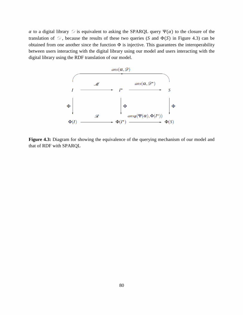
80
to a digital library D is equivalent to asking the SPARQL query ( ) to the closure of the
translation of D , because the results of these two queries (S and ( ) in Figure 4.3) can be
obtained from one another since the function is injective. This guarantees the interoperability
between users interacting with the digital library using our model and users interacting with the
digital library using the RDF translation of our model.
Figure 4.3: Diagram for showing the equivalence of the querying mechanism of our model and
that of RDF with SPARQL
81
Chapter 5
5 The actual implementation of the model
To show the feasibility of the theoretical model, we have designed and implemented a prototype
that is a simplified form of the model and query language.
Our prototype illustrates the theoretical model based on following aspects:
It supports various types of identifiers of the model
It fully supports the set of relations in the model that are used to model descriptions of
resources
It supports various types of variables of the query language
It supports simple conjunctive queries of the query language
In the practical aspect, our prototype supports the implementation of the model based on RDF
and SPARQL as follows:
It represents identifiers of the model in two various forms: the original form and the URI
form based on each specific schemata
It supports translating facts represented by relations in the model into RDF triples for
storing them in the RDF store, as well as, retrieving these facts from the RDF store for
displaying them on the reading/writing interfaces
It supports translating simple conjunctive queries of the query language into SPARQLs
and executing them on the RDF store. In which, returned results are a set of identifiers
supported by our protopype.
However, our prototype just supports conjunctive queries, while its interface only allows to users
carry out atomic queries. The reference table of our prototype that stores the associations
between identifiers and resources of the system is static. Moreover, although using URIs as
identifiers of the model makes the digital library ―consistent‖, our prototype hasn’t implemented
a rule base of axioms to ensure the completeness of the digital library yet.
Our system can be used by content providers for managing the knowledge of resources that are
either stored in the digital library, or reside outside the digital library; it can also be used by the
end users for querying the knowledge from the digital library. Built as a web application, the
82
system adopts the Google Web Toolkit (GWT) framework which facilitates the development of
web applications as desktop applications, performing business logic operations on server side, as
well as on client side. The Client Side logic operates within the web browser running on a user’s
local computer, while the Server Side logic operates on the web server hosting the application.
The system was built, tested, and debugged locally and then deployed on Google App Engine
(GAE). The system provides all the functionalities that were requested at the start time of this
work and are described in detail in this Chapter. In the future, the system can be expanded to
become a full fledged digital library management system.
This Chapter is organized as follows. Section 5.1 discusses the functional specification of the
system that has to be satisfied at deployment time. In particular, Section 5.3.1 presents the
definitions used throughout the document; Section 5.3.2 lists the technical requirements that have
to be met for achieving the desired functionality; Section 5.3.3 provides an in depth analysis for
the system’s functionality. Then, Section 5.2 describes the complete system’s architecture and
provides an in depth analysis of the internal functionality. The analysis of the architecture has
been broken into two parts; Section 5.1 describes the Client Side architecture, and Section 5.2
describes the Server Side architecture. Finally, Section 5.4 represents the user interface of the
system and describes how to use it.
5.1 Functional Specification
5.1.1 Definitions
Identifier: refers to any digital resource used as a reference to another resource in the digital
library. In our model, we have introduced various types of identifier for classes, properties,
schemas, descriptions and composable resources. They consist of: resource identifier, class
identifier, property identifier, schema identifier, description identifier and composable resource
identifier. Some of them have two kinds of representation: original form and URI form, and the
way to convert between them differs from one schema to another. For example, a resource in the
museum Louvre has its resource identifier represented in original form as Inv. 7738, and its
resource identifier represented in URI form as http://www.louvre.fr/7738. But another resource
in the RMN museum has its resource identifier represented in original form as PRP30; 90-
007895, and its resource identifier represented in URI form as http://www.rmn.fr/prp30/90-
007895. Therefore, we need to define some different kinds of identifiers for each specific
schema, for example, we define LouvreResourceID as the type of resource identifier of the
museum Louvre, we define JoncondeClassID as the type of class identifier of the database
Joconde,… Each type of identifier of such a schema uses specific principles of itself to form a
specific identifier and to convert between two different kinds of represention of it.
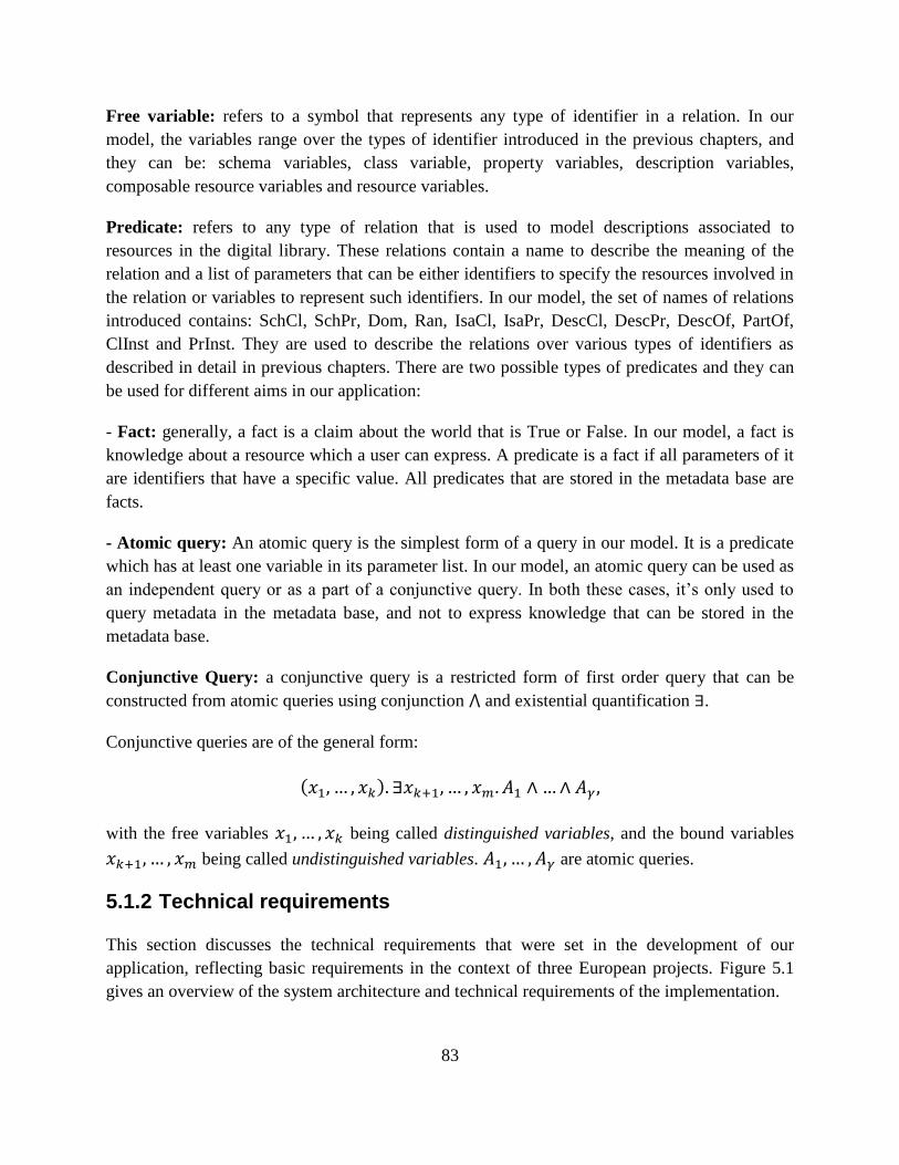
83
Free variable: refers to a symbol that represents any type of identifier in a relation. In our
model, the variables range over the types of identifier introduced in the previous chapters, and
they can be: schema variables, class variable, property variables, description variables,
composable resource variables and resource variables.
Predicate: refers to any type of relation that is used to model descriptions associated to
resources in the digital library. These relations contain a name to describe the meaning of the
relation and a list of parameters that can be either identifiers to specify the resources involved in
the relation or variables to represent such identifiers. In our model, the set of names of relations
introduced contains: SchCl, SchPr, Dom, Ran, IsaCl, IsaPr, DescCl, DescPr, DescOf, PartOf,
ClInst and PrInst. They are used to describe the relations over various types of identifiers as
described in detail in previous chapters. There are two possible types of predicates and they can
be used for different aims in our application:
- Fact: generally, a fact is a claim about the world that is True or False. In our model, a fact is
knowledge about a resource which a user can express. A predicate is a fact if all parameters of it
are identifiers that have a specific value. All predicates that are stored in the metadata base are
facts.
- Atomic query: An atomic query is the simplest form of a query in our model. It is a predicate
which has at least one variable in its parameter list. In our model, an atomic query can be used as
an independent query or as a part of a conjunctive query. In both these cases, it’s only used to
query metadata in the metadata base, and not to express knowledge that can be stored in the
metadata base.
Conjunctive Query: a conjunctive query is a restricted form of first order query that can be
constructed from atomic queries using conjunction and existential quantification .
Conjunctive queries are of the general form:
( )
with the free variables being called distinguished variables, and the bound variables
being called undistinguished variables. are atomic queries.
5.1.2 Technical requirements
This section discusses the technical requirements that were set in the development of our
application, reflecting basic requirements in the context of three European projects. Figure 5.1
gives an overview of the system architecture and technical requirements of the implementation.
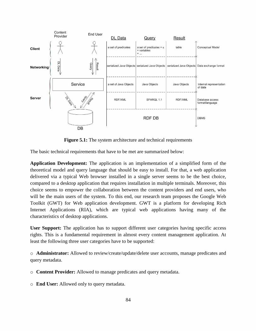
84
Figure 5.1: The system architecture and technical requirements
The basic technical requirements that have to be met are summarized below:
Application Development: The application is an implementation of a simplified form of the
theoretical model and query language that should be easy to install. For that, a web application
delivered via a typical Web browser installed in a single server seems to be the best choice,
compared to a desktop application that requires installation in multiple terminals. Moreover, this
choice seems to empower the collaboration between the content providers and end users, who
will be the main users of the system. To this end, our research team proposes the Google Web
Toolkit (GWT) for Web application development. GWT is a platform for developing Rich
Internet Applications (RIA), which are typical web applications having many of the
characteristics of desktop applications.
User Support: The application has to support different user categories having specific access
rights. This is a fundamental requirement in almost every content management application. At
least the following three user categories have to be supported:
o Administrator: Allowed to review/create/update/delete user accounts, manage predicates and
query metadata.
o Content Provider: Allowed to manage predicates and query metadata.
o End User: Allowed only to query metadata.
85
Conceptual Model:
Our application uses a set of predicates as data of the system. The user can perform some
operations with them, as well as the system can handle them. Meanwhile, queries of our digital
library are a set of predicates in which each predicate has at least one field as variable. Queries
use variables as their input parameters to make requests to query data. After a query is executed,
its result set is returned in tabular form.
Data exchange format:
GWT provides its own remote procedure calls (RPC's) which allow the GWT client to call
server-side methods. The implementation of GWT RPC is based on the servlet technology. GWT
allows Java objects to be sent directly between the client and the server, which are automatically
serialized by the framework. With GWT RPC the communication is almost transparent for the
GWT client and always asynchronous so that the client does not block during communication.
The server-side servlet is usually referred to as a ―service‖ and a remote procedure call is
referred to as an ―invoking a service‖. These objects can then be used on the client (UI) side.
Internal representation of data:
The objects and classes are the main part of the OOPs programming. Objects contain data and
code to manipulate the data as given by user. A class is an abstract description of a set of objects.
We must create the server-side Java classes to hold the data for the application.
To make RPC possible, the GWT support library must take the java objects that you supply in
Java, transmit them across the network, convert them into JavaScript objects, and then provide
them to the calling JavaScript code in the browser.
Database access format/language:
The most distinguishing feature of our application is that we are using an RDF-based data model
to store the information. To access RDF by existing interfaces, we decided to use Jena, a set of
Java API. In there, ARQ is a query engine for Jena that supports the SPARQL RDF Query
language and the W3C standard SPARQL Update language. We use SPARQL to query RDF
data and use SPARQL Update to change/delete/add data to a RDF Store.
Database Management System:
―Triple Store‖ is the common name given to a database management system for RDF Data.
These systems provide data management and data access via APIs and query languages to RDF
Data.
86
In reality, many Triple Stores are in fact Quad Stores, due to the need to maintain RDF Data
provenance within the data management system. Any Triple Store that supports Named Graph
functionality is more than likely a Quad Store.
5.1.3 The basic functionality of the application
Our application is the implementation of a prototype to show the feasibility of the theoretical
model and query language. It is basically used to facilitate the creation, retrieval, update and
deletion of predicates by content providers and to provide to end users basic services for
evaluating conjunctive queries. Its main functionality includes the following operations:
- Create/delete/update/view predicates
- Query metadata in the metadata base
- Create/delete/update/manage Users
The primary actors of the application are the users (i.e., physical persons) acting upon it to
achieve certain goals (e.g., the creation of a predicate in the system). According to the technical
requirements described in Section 5.1.2, these users are grouped in three categories (minimum
requirement) based on their access rights: (a) administrators, (b) content providers, and (c) end
users.
In the application, we need to provide the following web interface:
Predicates Management: is used mainly by the content providers to manage predicates in
the metadata base, but it is also used by the administrators. This page performs management
tasks of predicates based on a list of predicates taken from the metadata base. The main
functionalities of it are: viewing a predicate in the list, adding a new predicate into the
metadata base, deleting one or more existing predicates from metadata base and editing an
existing predicate in the metadata base.
Query Management: is used mainly by the end user to perform knowledge extraction from
metadata base. However, the administrators and the content providers also can use this page.
The page carries out knowledge extraction by allowing the user to create a simple query.
After the query is executed, the result set are displayed to the user in tabular format. Based
on the theoretical model, these results are identifiers so they can be displayed in two different
ways: the short form and the URI form.
User management: is used by administrator to manage user accounts. The main
functionalities of it are: creating a new user, editing the user accounts in the system.
The various use cases considered during the design of the interface are given in Appendix A.
87
5.2 System Architecture and Implementation
The actual implementation of a digital library, following our model, needs a Digital Library
Management System (DLMS) providing two basic functionalities:
(1) Data structures implementing the reference table and the metadata base, and operations for
manipulating them. In particular, we need operations for inserting and deleting associations
between identifiers and digital resources in the reference table, and similarly for inserting and
deleting tuples in the metadata base. The fundamental requirement for all these operations is that
they must be consistency preserving, according to the definition of consistency given in Section
2.2
(2) Implementation of our query language for discovering information from the digital library.
Of course, one can build such a management system from scratch or implement it on top of
existing technologies. In this thesis, however, we have assumed the second approach, and
discussed two different scenarios, one based on relational technology, the other based on RDF.
In order to enable interoperability of these scenarios, we have provided a mapping from our
model to RDF.
We have developed a prototype of such a management system for illustrating the implementation
of the scenario based on RDF. This section describes the complete system’s architecture,
identifies its basic components and provides an in depth analysis of the internal functionality.
For the development of the application we adopted several design patterns, which are presented
in detail in the following sections. Model-View-Presenter and Observer were used on the client
side, and a multi-tier architecture was implemented on the server side. Figure 5.2 displays the
overall system architecture. The analysis of the architecture has been broken into two parts;
Section 5.2.1 describes the Client Side architecture, and Section 5.2.2 describes the Server Side
architecture.
5.2.1 Client Side
The Client Side of the application is responsible for the interaction with the user. All the actions
performed by an individual using the system, are handled by the client side logic, which
undertakes the presentation of the information as well as the communication with the server
when needed. To achieve the scalability of the User Interface, and the distinction between the
components forming the client logic, a number of well-established patterns were adopted.
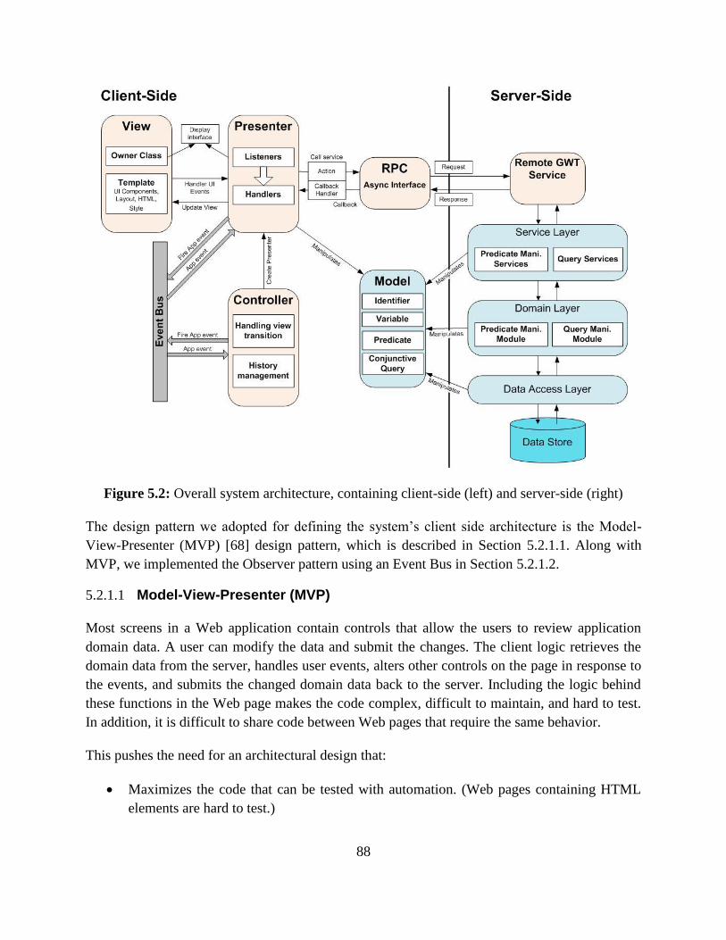
88
Figure 5.2: Overall system architecture, containing client-side (left) and server-side (right)
The design pattern we adopted for defining the system’s client side architecture is the Model-
View-Presenter (MVP) [68] design pattern, which is described in Section 5.2.1.1. Along with
MVP, we implemented the Observer pattern using an Event Bus in Section 5.2.1.2.
5.2.1.1 Model-View-Presenter (MVP)
Most screens in a Web application contain controls that allow the users to review application
domain data. A user can modify the data and submit the changes. The client logic retrieves the
domain data from the server, handles user events, alters other controls on the page in response to
the events, and submits the changed domain data back to the server. Including the logic behind
these functions in the Web page makes the code complex, difficult to maintain, and hard to test.
In addition, it is difficult to share code between Web pages that require the same behavior.
This pushes the need for an architectural design that:
Maximizes the code that can be tested with automation. (Web pages containing HTML
elements are hard to test.)
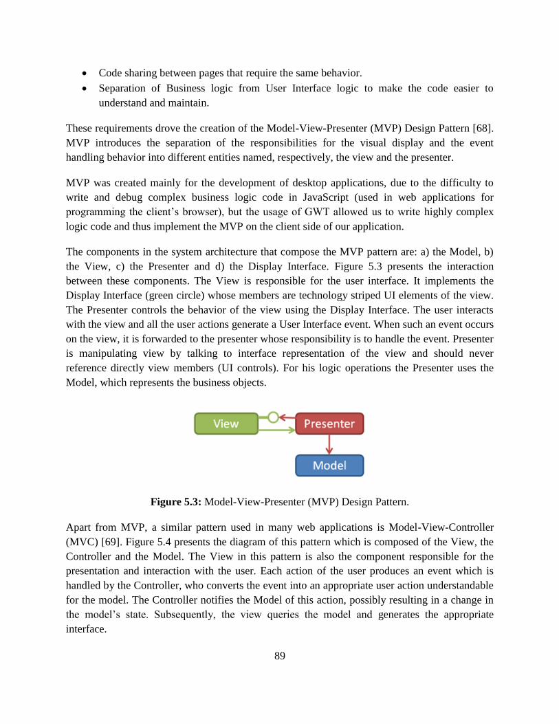
89
Code sharing between pages that require the same behavior.
Separation of Business logic from User Interface logic to make the code easier to
understand and maintain.
These requirements drove the creation of the Model-View-Presenter (MVP) Design Pattern [68].
MVP introduces the separation of the responsibilities for the visual display and the event
handling behavior into different entities named, respectively, the view and the presenter.
MVP was created mainly for the development of desktop applications, due to the difficulty to
write and debug complex business logic code in JavaScript (used in web applications for
programming the client’s browser), but the usage of GWT allowed us to write highly complex
logic code and thus implement the MVP on the client side of our application.
The components in the system architecture that compose the MVP pattern are: a) the Model, b)
the View, c) the Presenter and d) the Display Interface. Figure 5.3 presents the interaction
between these components. The View is responsible for the user interface. It implements the
Display Interface (green circle) whose members are technology striped UI elements of the view.
The Presenter controls the behavior of the view using the Display Interface. The user interacts
with the view and all the user actions generate a User Interface event. When such an event occurs
on the view, it is forwarded to the presenter whose responsibility is to handle the event. Presenter
is manipulating view by talking to interface representation of the view and should never
reference directly view members (UI controls). For his logic operations the Presenter uses the
Model, which represents the business objects.
Figure 5.3: Model-View-Presenter (MVP) Design Pattern.
Apart from MVP, a similar pattern used in many web applications is Model-View-Controller
(MVC) [69]. Figure 5.4 presents the diagram of this pattern which is composed of the View, the
Controller and the Model. The View in this pattern is also the component responsible for the
presentation and interaction with the user. Each action of the user produces an event which is
handled by the Controller, who converts the event into an appropriate user action understandable
for the model. The Controller notifies the Model of this action, possibly resulting in a change in
the model’s state. Subsequently, the view queries the model and generates the appropriate
interface.
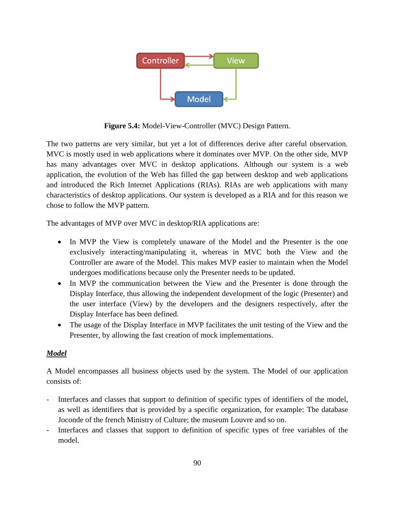
90
Figure 5.4: Model-View-Controller (MVC) Design Pattern.
The two patterns are very similar, but yet a lot of differences derive after careful observation.
MVC is mostly used in web applications where it dominates over MVP. On the other side, MVP
has many advantages over MVC in desktop applications. Although our system is a web
application, the evolution of the Web has filled the gap between desktop and web applications
and introduced the Rich Internet Applications (RIAs). RIAs are web applications with many
characteristics of desktop applications. Our system is developed as a RIA and for this reason we
chose to follow the MVP pattern.
The advantages of MVP over MVC in desktop/RIA applications are:
In MVP the View is completely unaware of the Model and the Presenter is the one
exclusively interacting/manipulating it, whereas in MVC both the View and the
Controller are aware of the Model. This makes MVP easier to maintain when the Model
undergoes modifications because only the Presenter needs to be updated.
In MVP the communication between the View and the Presenter is done through the
Display Interface, thus allowing the independent development of the logic (Presenter) and
the user interface (View) by the developers and the designers respectively, after the
Display Interface has been defined.
The usage of the Display Interface in MVP facilitates the unit testing of the View and the
Presenter, by allowing the fast creation of mock implementations.
Model
A Model encompasses all business objects used by the system. The Model of our application
consists of:
- Interfaces and classes that support to definition of specific types of identifiers of the model,
as well as identifiers that is provided by a specific organization, for example: The database
Joconde of the french Ministry of Culture; the museum Louvre and so on.
- Interfaces and classes that support to definition of specific types of free variables of the
model.
91
- Interfaces and classes that support to definition of specific types of predicates of the model.
Note that, if all fields of a specific predicate are identifiers then it is a fact. Otherwise, if at
least one field of a specific predicate is a variable then it is an atomic query.
- A class that contains all the information of the conjunctive query. Each conjunctive query
includes an array of atomic queries.
- A class that contains all the data of the result set of query execution.
The interfaces and classes of the Model used for the implementation of our application are given
in Appendix B.
View
In the MVP pattern, the view is responsible for all the information presentation (colors, borders,
UI layout) and the management of the controls on a page or part of a page. All HTML and the
StyleSheets are handled by views.
In our system, each view is a composite widget, aggregating a set of simple widgets. Simple
widgets refer to the simple HTML elements (e.g. tables, labels, buttons, textboxes, forms, images
etc.) The views dynamically create and manipulate these widgets, according to the system
actions, or use them to capture user actions. Moreover, views have no notion of the model. That
is to say a view doesn't know what it is displaying; it simply knows that it has, for example, 3
labels, 3 textboxes, and 2 buttons that are organized in a vertical fashion.
Each view is coupled with one presenter. The presenter instantiates the view, controls it
throughout its lifecycle and destroys it when the time comes. During instantiation, the presenter
instructs the view where to ―sit‖ on the screen. This way a single web page can be composed by
multiple presenters manipulations various views.
When the user interacts with the web page, a browser event takes place. This event can be traced
using GWT mechanisms, and handled whichever way needed. The important events are handled
by the views, or delegated to the corresponding presenters, if the presenter has asked to be
informed about the specific type of event. In turn, the presenter might instruct the view to update
some of its visual parts, based on the event. For example, if the user clicks the delete button next
to a predicate in a list, the view delegated the click event to the presenter. The presenter informs
the server to delete the predicate, and then instructs the view to remove the predicate from the
list.
Below, we quote a brief description for each View we have implemented in our application.
- A view that allows the users to login to the system
- A view that allows content providers to choose the relation name of a predicate.
92
- Views that allow content providers to view, add and edit a specific predicate.
- A view that allows content providers to view the list of predicates and delete a set of selected
predicates.
- A view that allows content providers to choose the relation name of an atomic query.
- Views that allow end users to create, review and execute a specific atomic query.
- A view allows end users to view the results of query execution in two different formats of
identifiers.
Particularly, the classes of the views used for the implementation of our application are given in
Appendix B.
Presenter
A Presenter contains all of the client side logic of our application. It is the key in MVP design
pattern, for it is a bridge between the Model and the View. As a general rule, for every View
there is a presenter that instantiates and manipulates it, but there might be cases where one
presenter needs to control multiple views. The presenter has handlers for the events that take
place in his view/s or in the application in general (see Event Bus in Section 5.2.1.2). The
lifecycle of a presenter is composed of four phases.
Initialization phase: The presenter initializes its corresponding view/s, and instructs
them where to deploy. In addition, the presenter registers handlers to the crucial UI
events and application events. When the initialization and handler registration finish, the
presenter goes into the sleeping phase.
Sleeping phase: This is the phase where the presenter does nothing but wait for a UI
event from the view, or an application event.
Operating phase: When an already registered event is raised, the presenter wakes up and
handles it (using its UI/App Event Handlers) by contacting the server, updating the view
or even raising new events.
Termination phase: When the user leaves the application, the presenter goes into the
termination phase, before being destroyed. During this phase, the presenter might need to
inform the server for the termination.
The communication of the presenter with the services residing on the server, takes place through
the RPC async interface. More on this subject can be found in Section 5.2.1.3.
As already stated, the presenter has no knowledge of any widget-based code inside the view and
all the interaction with the view is done through the Display Interface.
Below, we quote a brief description for each Presenter we have implemented in our application.
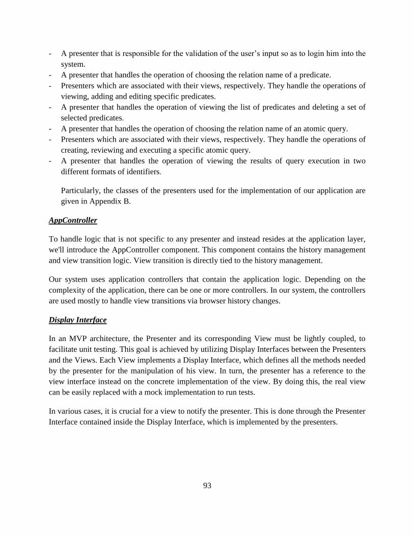
93
- A presenter that is responsible for the validation of the user’s input so as to login him into the
system.
- A presenter that handles the operation of choosing the relation name of a predicate.
- Presenters which are associated with their views, respectively. They handle the operations of
viewing, adding and editing specific predicates.
- A presenter that handles the operation of viewing the list of predicates and deleting a set of
selected predicates.
- A presenter that handles the operation of choosing the relation name of an atomic query.
- Presenters which are associated with their views, respectively. They handle the operations of
creating, reviewing and executing a specific atomic query.
- A presenter that handles the operation of viewing the results of query execution in two
different formats of identifiers.
Particularly, the classes of the presenters used for the implementation of our application are
given in Appendix B.
AppController
To handle logic that is not specific to any presenter and instead resides at the application layer,
we'll introduce the AppController component. This component contains the history management
and view transition logic. View transition is directly tied to the history management.
Our system uses application controllers that contain the application logic. Depending on the
complexity of the application, there can be one or more controllers. In our system, the controllers
are used mostly to handle view transitions via browser history changes.
Display Interface
In an MVP architecture, the Presenter and its corresponding View must be lightly coupled, to
facilitate unit testing. This goal is achieved by utilizing Display Interfaces between the Presenters
and the Views. Each View implements a Display Interface, which defines all the methods needed
by the presenter for the manipulation of his view. In turn, the presenter has a reference to the
view interface instead on the concrete implementation of the view. By doing this, the real view
can be easily replaced with a mock implementation to run tests.
In various cases, it is crucial for a view to notify the presenter. This is done through the Presenter
Interface contained inside the Display Interface, which is implemented by the presenters.
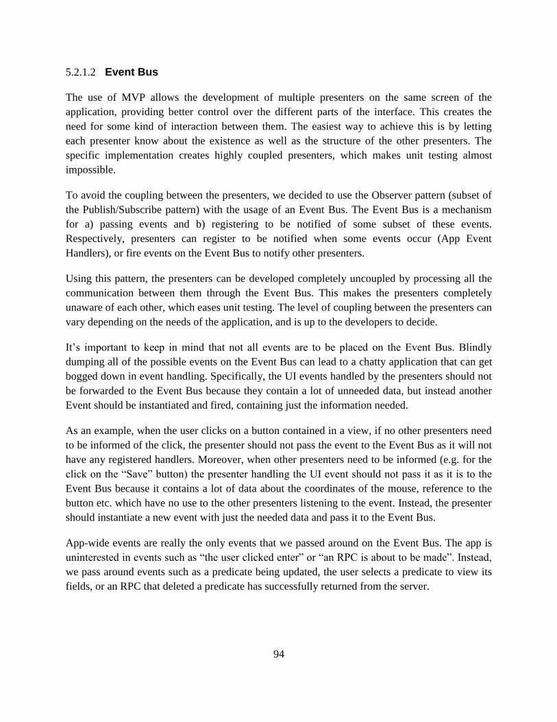
94
5.2.1.2 Event Bus
The use of MVP allows the development of multiple presenters on the same screen of the
application, providing better control over the different parts of the interface. This creates the
need for some kind of interaction between them. The easiest way to achieve this is by letting
each presenter know about the existence as well as the structure of the other presenters. The
specific implementation creates highly coupled presenters, which makes unit testing almost
impossible.
To avoid the coupling between the presenters, we decided to use the Observer pattern (subset of
the Publish/Subscribe pattern) with the usage of an Event Bus. The Event Bus is a mechanism
for a) passing events and b) registering to be notified of some subset of these events.
Respectively, presenters can register to be notified when some events occur (App Event
Handlers), or fire events on the Event Bus to notify other presenters.
Using this pattern, the presenters can be developed completely uncoupled by processing all the
communication between them through the Event Bus. This makes the presenters completely
unaware of each other, which eases unit testing. The level of coupling between the presenters can
vary depending on the needs of the application, and is up to the developers to decide.
It’s important to keep in mind that not all events are to be placed on the Event Bus. Blindly
dumping all of the possible events on the Event Bus can lead to a chatty application that can get
bogged down in event handling. Specifically, the UI events handled by the presenters should not
be forwarded to the Event Bus because they contain a lot of unneeded data, but instead another
Event should be instantiated and fired, containing just the information needed.
As an example, when the user clicks on a button contained in a view, if no other presenters need
to be informed of the click, the presenter should not pass the event to the Event Bus as it will not
have any registered handlers. Moreover, when other presenters need to be informed (e.g. for the
click on the ―Save‖ button) the presenter handling the UI event should not pass it as it is to the
Event Bus because it contains a lot of data about the coordinates of the mouse, reference to the
button etc. which have no use to the other presenters listening to the event. Instead, the presenter
should instantiate a new event with just the needed data and pass it to the Event Bus.
App-wide events are really the only events that we passed around on the Event Bus. The app is
uninterested in events such as ―the user clicked enter‖ or ―an RPC is about to be made‖. Instead,
we pass around events such as a predicate being updated, the user selects a predicate to view its
fields, or an RPC that deleted a predicate has successfully returned from the server.
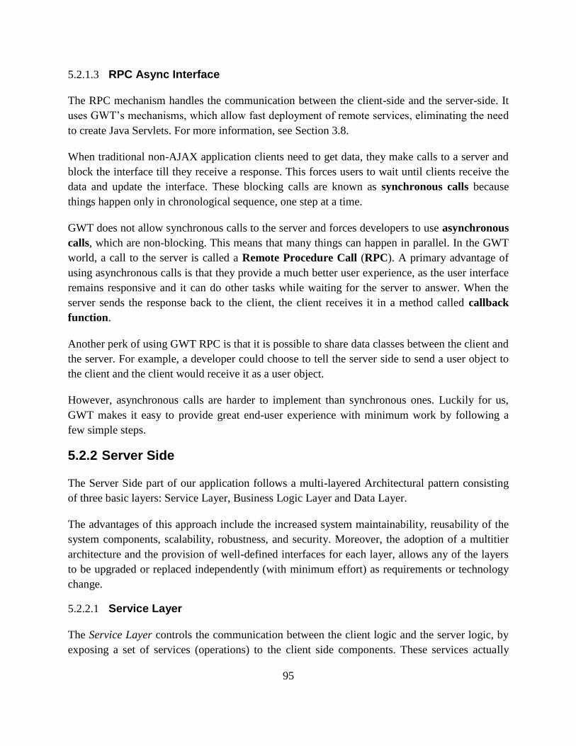
95
5.2.1.3 RPC Async Interface
The RPC mechanism handles the communication between the client-side and the server-side. It
uses GWT’s mechanisms, which allow fast deployment of remote services, eliminating the need
to create Java Servlets. For more information, see Section 3.8.
When traditional non-AJAX application clients need to get data, they make calls to a server and
block the interface till they receive a response. This forces users to wait until clients receive the
data and update the interface. These blocking calls are known as synchronous calls because
things happen only in chronological sequence, one step at a time.
GWT does not allow synchronous calls to the server and forces developers to use asynchronous
calls, which are non-blocking. This means that many things can happen in parallel. In the GWT
world, a call to the server is called a Remote Procedure Call (RPC). A primary advantage of
using asynchronous calls is that they provide a much better user experience, as the user interface
remains responsive and it can do other tasks while waiting for the server to answer. When the
server sends the response back to the client, the client receives it in a method called callback
function.
Another perk of using GWT RPC is that it is possible to share data classes between the client and
the server. For example, a developer could choose to tell the server side to send a user object to
the client and the client would receive it as a user object.
However, asynchronous calls are harder to implement than synchronous ones. Luckily for us,
GWT makes it easy to provide great end-user experience with minimum work by following a
few simple steps.
5.2.2 Server Side
The Server Side part of our application follows a multi-layered Architectural pattern consisting
of three basic layers: Service Layer, Business Logic Layer and Data Layer.
The advantages of this approach include the increased system maintainability, reusability of the
system components, scalability, robustness, and security. Moreover, the adoption of a multitier
architecture and the provision of well-defined interfaces for each layer, allows any of the layers
to be upgraded or replaced independently (with minimum effort) as requirements or technology
change.
5.2.2.1 Service Layer
The Service Layer controls the communication between the client logic and the server logic, by
exposing a set of services (operations) to the client side components. These services actually
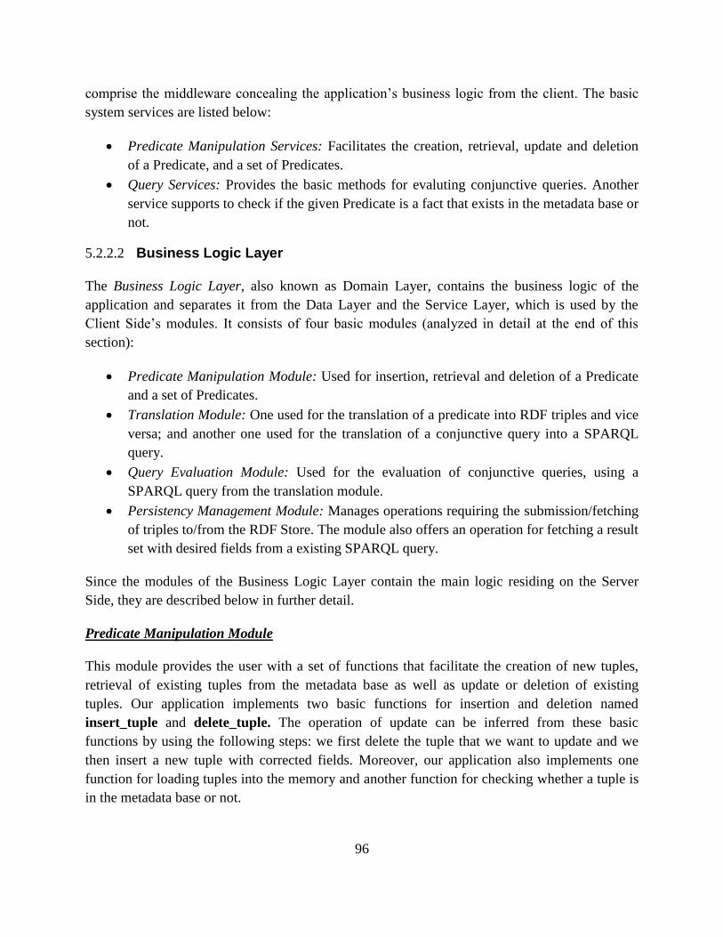
96
comprise the middleware concealing the application’s business logic from the client. The basic
system services are listed below:
Predicate Manipulation Services: Facilitates the creation, retrieval, update and deletion
of a Predicate, and a set of Predicates.
Query Services: Provides the basic methods for evaluting conjunctive queries. Another
service supports to check if the given Predicate is a fact that exists in the metadata base or
not.
5.2.2.2 Business Logic Layer
The Business Logic Layer, also known as Domain Layer, contains the business logic of the
application and separates it from the Data Layer and the Service Layer, which is used by the
Client Side’s modules. It consists of four basic modules (analyzed in detail at the end of this
section):
Predicate Manipulation Module: Used for insertion, retrieval and deletion of a Predicate
and a set of Predicates.
Translation Module: One used for the translation of a predicate into RDF triples and vice
versa; and another one used for the translation of a conjunctive query into a SPARQL
query.
Query Evaluation Module: Used for the evaluation of conjunctive queries, using a
SPARQL query from the translation module.
Persistency Management Module: Manages operations requiring the submission/fetching
of triples to/from the RDF Store. The module also offers an operation for fetching a result
set with desired fields from a existing SPARQL query.
Since the modules of the Business Logic Layer contain the main logic residing on the Server
Side, they are described below in further detail.
Predicate Manipulation Module
This module provides the user with a set of functions that facilitate the creation of new tuples,
retrieval of existing tuples from the metadata base as well as update or deletion of existing
tuples. Our application implements two basic functions for insertion and deletion named
insert_tuple and delete_tuple. The operation of update can be inferred from these basic
functions by using the following steps: we first delete the tuple that we want to update and we
then insert a new tuple with corrected fields. Moreover, our application also implements one
function for loading tuples into the memory and another function for checking whether a tuple is
in the metadata base or not.
97
The first function insert_tuple is used to insert one tuple into the RDF store. It simply gets a
tuple as the input parameter, translates the tuple into one or more triples by using the function
TupletoTriple of the Translation Module, and then inserts all of them into the RDF store. The
function returns a Boolean value, true on success, false on failure.
To insert each triple into the RDF store, we use a function called insert_triple. This function
extracts triplet subject, predicate, and object from the input triple, then uses their URLs to form a
triple pattern of a SPARUL request. Note that SPARUL, or SPARQL/Update, is an extension to
the SPARQL query language that provides the ability to add, update, and delete RDF data held
within a triple store. In our application, the following SPARUL request is used to describe one
RDF triple to be inserted into the default graph of the Graph Store:
INSERT DATA
{
<subject.getURI()> <predicate.getURI()> <object.getURI()>
}
The SPARUL request then will be passed as an input parameter to the function update_dl in
Persistency Management Module to carry out the request. After this step, the triple will actually
be inserted into the RDF Store.
Meanwhile, the second function delete_tuple is used to delete one tuple from the RDF store. It
also gets a tuple as the input parameter, translates the tuple into one or more triples by using the
function TupletoTriple of the Translation Module, and then deletes all of them from the RDF
store. The function returns a Boolean value, true on success, false on failure.
However, we need to pay attention to a special case, that is when we have at least two tuples in
the metadata base that have one triple the same after translated into triples, such as DescCl(d, s,
c) and DescPr(d, s, p, i), and we need to delete one of them. Indeed, based on the translation
rules in Table IV, the tuple DescCl(d, s, c) is translated into two triples ( ),
and ( ) and the tuple DescPr(d, s, p, i) is translated into two triples
( ), and ( ) . They clearly have the same triple
( ) in the translation form. In principle, the RDF Store only stores this triple
one time although it can be inserted into the RDF Store more than one time. We can imply that it
will be shared by both of tuples, so we have no problem when we perform the function
insert_tuple to insert these tuples into the RDF store. But when we delete one of these tuples,
the problem can occur due to the remaining tuple can lose the triple that has been shared with the
deleted tuple and we don’t have enough information to restore the remaining tuple, if needed.
98
To overcome this problem, we only delete the triple in format ( ) of a tuple,
if and only if, at that time, it isn’t shared by one or more other tuples. In our application, we use
an algorithm that includes the following steps:
1, translates the tuple into the list L that includes one or two triples by using the function
TupletoTriple of the Translation Module.
2, if the list L includes only one triple, this means that the tuple isn’t in the DescCl or DescPr
relations, the algorithm simply deletes the triple and then the algorithm finishes.
else if the list L includes two triples, this means that the tuple is in the DescCl or DescPr
relations and it includes a triple in the format ( ), the algorithm first deletes
the other triple of the list L.
3, In the next step, the algorithm checks in the RDF store if there is exist any triple that also can
combine the triple in the format ( ) to form at least one different tuple in the
DescCl or DescPr relations. If it exists, the algothrim fishnishes but doesn’t delete the triple in
the format ( ), else the algothrim deletes the triple in the format
( ) and then it finishes.
To delete each triple from the RDF store, we use a function called delete_triple. This function
extracts triplet subject, predicate, and object from the input triple, then uses their URLs to form a
triple pattern of a SPARUL request. In our application, the following SPARUL request is used to
describe one RDF triple to be deleted from the default graph of the Graph Store:
DELETE WHERE
{
<subject.getURI()> <predicate.getURI()> <object.getURI()>
}
The SPARUL request then will be passed as an input parameter to the function update_dl in
Persistency Management Module to carry out the request. After this step, the triple will actually
be deleted from the RDF Store.
To load tuples into the memory, we use the function load_tuples that simply carries out the
following SPARQL query to retrieve all triples in the RDF store:
SELECT ?s ?p ?o { ?s ?p ?o }
The result returned is a DTO object in tabular form that contains all triples in the RDF store. In
the future, we can design some functions that are more powerful to load each part of the
99
metadata base individually, or to load tuples that satisfy some given conditions. Then, the
returned object is passed to a function to restore a list of all related tuples.
To check whether a tuple is in the metadata base or not, we use the function isexistentfact that
accepts a tuple as the input parameter, translates it into one or more triples and then checks
whether each triple existed in the metadata base or not by using a SPARQL query to search it in
the RDF store.
Translation Module
To facilitate the implementation of our model in RDF, the translation module provides one basic
functionality for translating a tuple into one or more RDF triples and vice versa.
The functionality works through a translator that uses (a) an auxiliary function to translate
identifiers into URIs; and (b) a major function named TupletoTriple to map from tuples to
triples that use the auxiliary function on identifiers. The rules in the Table 4.1 except two rules
(TR11 and TR12 for facilitating query expression) are used to translate any tuple into one or
more RDF triples. While the rules TR7 and TR8 are used to translate a tuple in DescCl or DescPr
into two triples, the others are used to translate a tuple into only one triple.
In the reverse direction, the translator also provides (a) an auxiliary function to translate URIs
into identifiers; and (b) a major function named TripletoTuple to map from triples to tuples that
use the auxiliary function on URIs.
To support for translation, the translator uses the RDF vocabulary that we denote as RDFDL.
The vocabulary is the set of RDF classes and properties that will appear in the RDF triples
resulting from the translation of tuples into triples. These RDF classes and properties also are
used to identify to which relation the triple belongs in the translation of triples into tuples. The
vocabulary is the union of two vocabularies:
A subset of the RDFS vocabulary, required to translate the schema relation names, namely:
Dom, Ran, IsaCl, IsaPr, ClInst. We can obtain it in our application by using the set of RDFS
vocabulary from the API of Apache Jena framework.
A new vocabulary, including the URIs for translating those relation names that have no
corresponding property in RDFS, namely: DescCl, DescPr, DescOf, and PartOf. We can
obtain it in our application by creating a vocabulary class that includes all these URIs as
properties of the class.
Query Evaluation Module
100
The Query Evaluation Module is responsible for the evaluation of conjunctive queries by first
creating a SPARQL query and then using it as an input parameter of the function select_dl to
obtain the query results in the data transfer object format.
In a SPARQL query, the SELECT clause lists the free variables, while the WHERE clause gives
a graph pattern describing the properties of the result. So, to create a complete SPARQL query,
we first generate each of these clauses separately. In particular,
1, To obtain the SELECT clause, we use a function, called getFreeVariables, that first extracts
from a conjunctive query the set of the free variables in our query language and then translates
them into a string that is a list of free variables in SPARQL query. The function uses a simple
algorithm that consists of two steps:
In the first step, the algorithm traverses the list of parameters of each atomic query in the
conjunctive query one time. If a parameter is a free variable in our query language then it will be
added to a set that is initialized to an empty set at the start time. Finally, we obtain the set of free
variables in our query language that will be used in next step.
In the second step, the algorithm also traverses the set one time to add each individual free
variable in our query language with a question mark ahead of it to a list in the string format. At
the end of the algorithm, the string that we obtain is a list of free variables in SPARQL query.
2, To obtain the WHERE clause, we use a function, called getGraphPattern, that maps a
conjunctive query into an equivalent graph pattern. This function uses another function named
getGraphPatternOfAtomicQuery to obtain the graph pattern of any atomic query which is
either an independent query or a component part of the conjunctive query. Then, if the input
query is actually a conjunctive query, we will obtain the graph pattern of it by using the
SPARQL AND operator, which is expressed as ―.‖, to join all graph patterns of all atomic
queries which are component parts of the conjunctive query.
In detail, the function getGraphPatternOfAtomicQuery uses an auxiliary function to translate
identifiers into URIs and variables in our query language into SPARQL variables and it supports
the generation of the graph pattern of any atomic query by using the translation rules that we
have defined in Chapter 4. In fact, the function considers two separate cases that an atomic query
can belong to: (a) The atomic query has no variable that is a class, a property or a schema
variable and (b) the atomic query has at least one schema or class or property variable. The
function has been implemented to solve these cases as explained in Chapter 4.
The SPARQL query that is a combination of two these clauses will be used as the input of the
function select_dl of Persistency Management Module. The function will carry out the query and
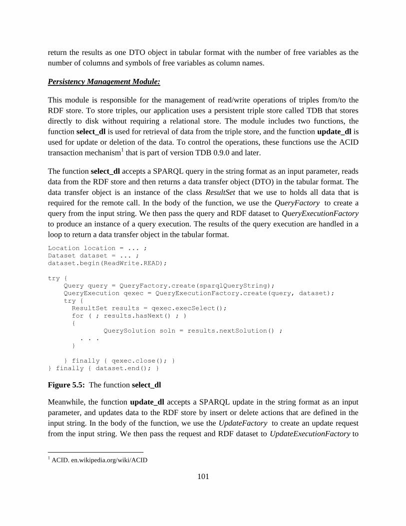
101
return the results as one DTO object in tabular format with the number of free variables as the
number of columns and symbols of free variables as column names.
Persistency Management Module:
This module is responsible for the management of read/write operations of triples from/to the
RDF store. To store triples, our application uses a persistent triple store called TDB that stores
directly to disk without requiring a relational store. The module includes two functions, the
function select_dl is used for retrieval of data from the triple store, and the function update_dl is
used for update or deletion of the data. To control the operations, these functions use the ACID
transaction mechanism1 that is part of version TDB 0.9.0 and later.
The function select_dl accepts a SPARQL query in the string format as an input parameter, reads
data from the RDF store and then returns a data transfer object (DTO) in the tabular format. The
data transfer object is an instance of the class ResultSet that we use to holds all data that is
required for the remote call. In the body of the function, we use the QueryFactory to create a
query from the input string. We then pass the query and RDF dataset to QueryExecutionFactory
to produce an instance of a query execution. The results of the query execution are handled in a
loop to return a data transfer object in the tabular format.
Location location = ... ;
Dataset dataset = ... ;
dataset.begin(ReadWrite.READ);
try {
Query query = QueryFactory.create(sparqlQueryString);
QueryExecution qexec = QueryExecutionFactory.create(query, dataset);
try {
ResultSet results = qexec.execSelect();
for ( ; results.hasNext() ; )
{
QuerySolution soln = results.nextSolution() ;
. . .
}
} finally { qexec.close(); }
} finally { dataset.end(); }
Figure 5.5: The function select_dl
Meanwhile, the function update_dl accepts a SPARQL update in the string format as an input
parameter, and updates data to the RDF store by insert or delete actions that are defined in the
input string. In the body of the function, we use the UpdateFactory to create an update request
from the input string. We then pass the request and RDF dataset to UpdateExecutionFactory to
1 ACID. en.wikipedia.org/wiki/ACID
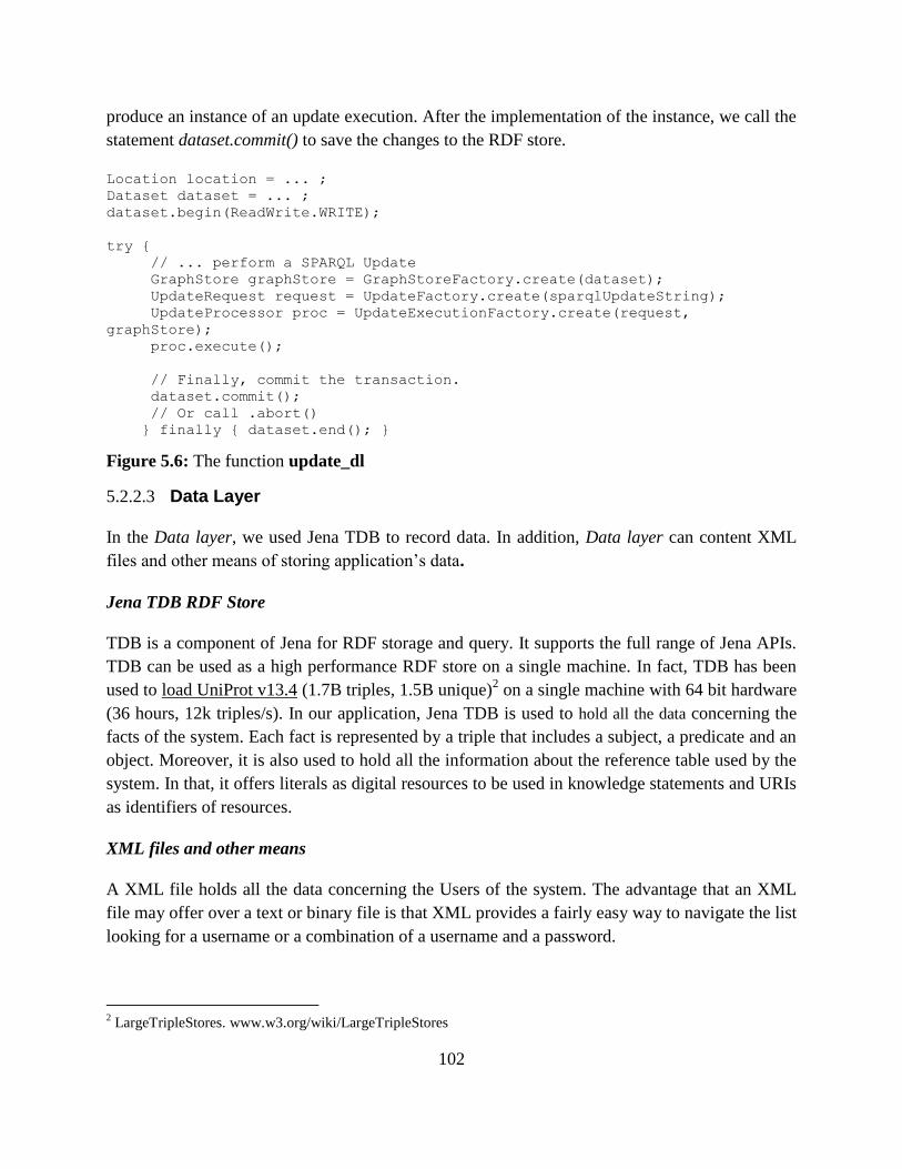
102
produce an instance of an update execution. After the implementation of the instance, we call the
statement dataset.commit() to save the changes to the RDF store.
Location location = ... ;
Dataset dataset = ... ;
dataset.begin(ReadWrite.WRITE);
try {
// ... perform a SPARQL Update
GraphStore graphStore = GraphStoreFactory.create(dataset);
UpdateRequest request = UpdateFactory.create(sparqlUpdateString);
UpdateProcessor proc = UpdateExecutionFactory.create(request,
graphStore);
proc.execute();
// Finally, commit the transaction.
dataset.commit();
// Or call .abort()
} finally { dataset.end(); }
Figure 5.6: The function update_dl
5.2.2.3 Data Layer
In the Data layer, we used Jena TDB to record data. In addition, Data layer can content XML
files and other means of storing application’s data.
Jena TDB RDF Store
TDB is a component of Jena for RDF storage and query. It supports the full range of Jena APIs.
TDB can be used as a high performance RDF store on a single machine. In fact, TDB has been
used to load UniProt v13.4 (1.7B triples, 1.5B unique)2 on a single machine with 64 bit hardware
(36 hours, 12k triples/s). In our application, Jena TDB is used to hold all the data concerning the
facts of the system. Each fact is represented by a triple that includes a subject, a predicate and an
object. Moreover, it is also used to hold all the information about the reference table used by the
system. In that, it offers literals as digital resources to be used in knowledge statements and URIs
as identifiers of resources.
XML files and other means
A XML file holds all the data concerning the Users of the system. The advantage that an XML
file may offer over a text or binary file is that XML provides a fairly easy way to navigate the list
looking for a username or a combination of a username and a password.
2 LargeTripleStores. www.w3.org/wiki/LargeTripleStores
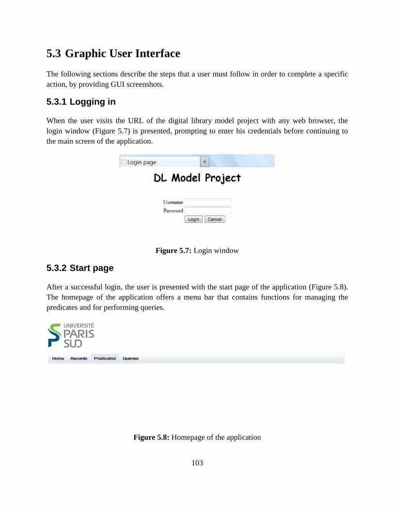
103
5.3 Graphic User Interface
The following sections describe the steps that a user must follow in order to complete a specific
action, by providing GUI screenshots.
5.3.1 Logging in
When the user visits the URL of the digital library model project with any web browser, the
login window (Figure 5.7) is presented, prompting to enter his credentials before continuing to
the main screen of the application.
Figure 5.7: Login window
5.3.2 Start page
After a successful login, the user is presented with the start page of the application (Figure 5.8).
The homepage of the application offers a menu bar that contains functions for managing the
predicates and for performing queries.
Figure 5.8: Homepage of the application
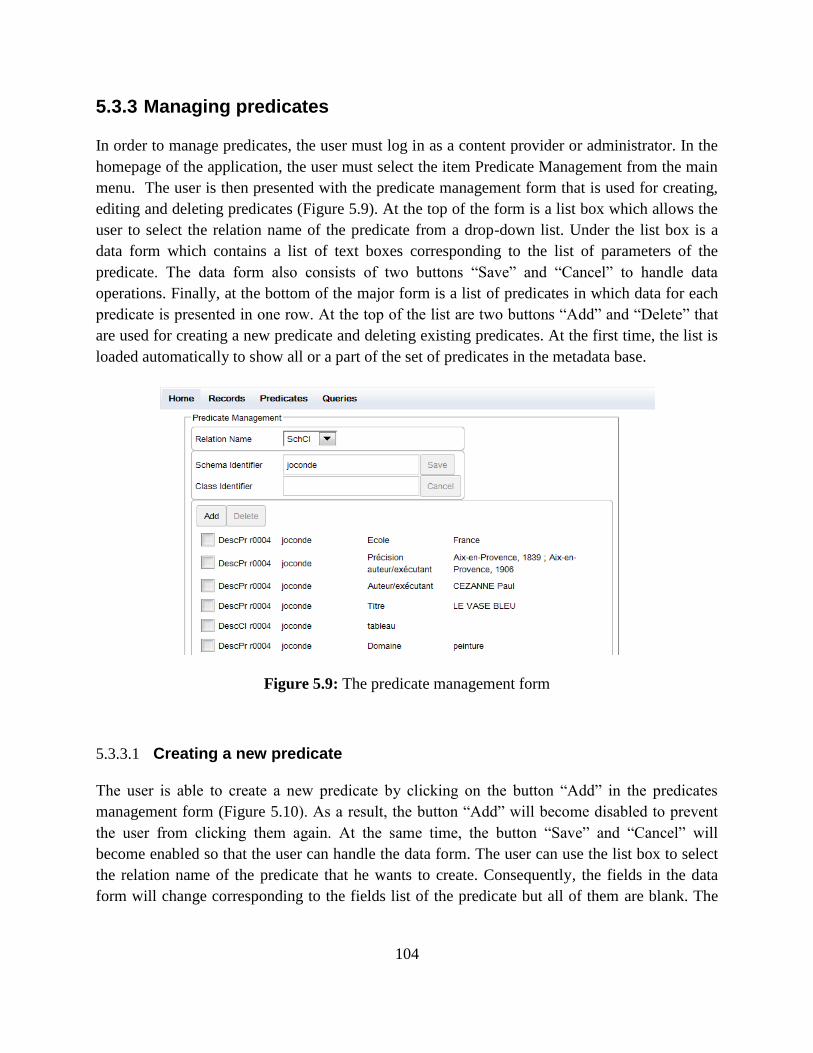
104
5.3.3 Managing predicates
In order to manage predicates, the user must log in as a content provider or administrator. In the
homepage of the application, the user must select the item Predicate Management from the main
menu. The user is then presented with the predicate management form that is used for creating,
editing and deleting predicates (Figure 5.9). At the top of the form is a list box which allows the
user to select the relation name of the predicate from a drop-down list. Under the list box is a
data form which contains a list of text boxes corresponding to the list of parameters of the
predicate. The data form also consists of two buttons ―Save‖ and ―Cancel‖ to handle data
operations. Finally, at the bottom of the major form is a list of predicates in which data for each
predicate is presented in one row. At the top of the list are two buttons ―Add‖ and ―Delete‖ that
are used for creating a new predicate and deleting existing predicates. At the first time, the list is
loaded automatically to show all or a part of the set of predicates in the metadata base.
Figure 5.9: The predicate management form
5.3.3.1 Creating a new predicate
The user is able to create a new predicate by clicking on the button ―Add‖ in the predicates
management form (Figure 5.10). As a result, the button ―Add‖ will become disabled to prevent
the user from clicking them again. At the same time, the button ―Save‖ and ―Cancel‖ will
become enabled so that the user can handle the data form. The user can use the list box to select
the relation name of the predicate that he wants to create. Consequently, the fields in the data
form will change corresponding to the fields list of the predicate but all of them are blank. The
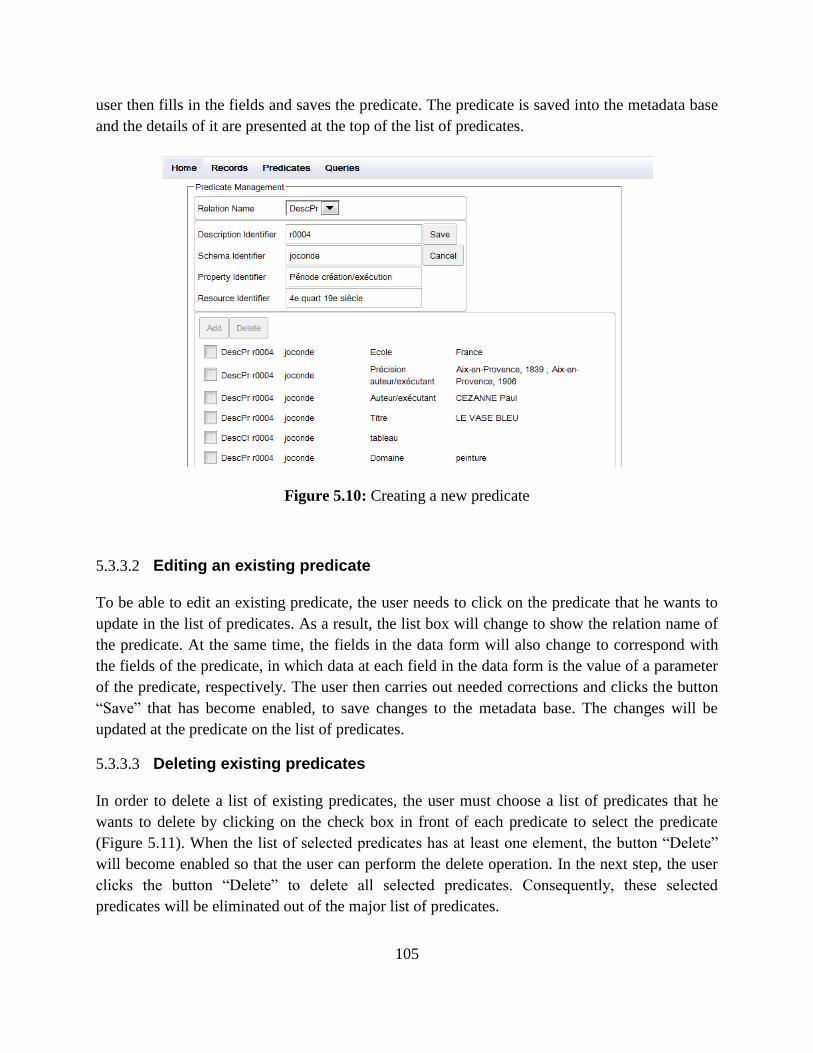
105
user then fills in the fields and saves the predicate. The predicate is saved into the metadata base
and the details of it are presented at the top of the list of predicates.
Figure 5.10: Creating a new predicate
5.3.3.2 Editing an existing predicate
To be able to edit an existing predicate, the user needs to click on the predicate that he wants to
update in the list of predicates. As a result, the list box will change to show the relation name of
the predicate. At the same time, the fields in the data form will also change to correspond with
the fields of the predicate, in which data at each field in the data form is the value of a parameter
of the predicate, respectively. The user then carries out needed corrections and clicks the button
―Save‖ that has become enabled, to save changes to the metadata base. The changes will be
updated at the predicate on the list of predicates.
5.3.3.3 Deleting existing predicates
In order to delete a list of existing predicates, the user must choose a list of predicates that he
wants to delete by clicking on the check box in front of each predicate to select the predicate
(Figure 5.11). When the list of selected predicates has at least one element, the button ―Delete‖
will become enabled so that the user can perform the delete operation. In the next step, the user
clicks the button ―Delete‖ to delete all selected predicates. Consequently, these selected
predicates will be eliminated out of the major list of predicates.
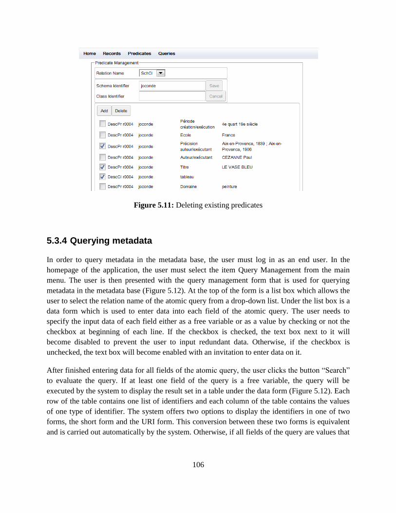
106
Figure 5.11: Deleting existing predicates
5.3.4 Querying metadata
In order to query metadata in the metadata base, the user must log in as an end user. In the
homepage of the application, the user must select the item Query Management from the main
menu. The user is then presented with the query management form that is used for querying
metadata in the metadata base (Figure 5.12). At the top of the form is a list box which allows the
user to select the relation name of the atomic query from a drop-down list. Under the list box is a
data form which is used to enter data into each field of the atomic query. The user needs to
specify the input data of each field either as a free variable or as a value by checking or not the
checkbox at beginning of each line. If the checkbox is checked, the text box next to it will
become disabled to prevent the user to input redundant data. Otherwise, if the checkbox is
unchecked, the text box will become enabled with an invitation to enter data on it.
After finished entering data for all fields of the atomic query, the user clicks the button ―Search‖
to evaluate the query. If at least one field of the query is a free variable, the query will be
executed by the system to display the result set in a table under the data form (Figure 5.12). Each
row of the table contains one list of identifiers and each column of the table contains the values
of one type of identifier. The system offers two options to display the identifiers in one of two
forms, the short form and the URI form. This conversion between these two forms is equivalent
and is carried out automatically by the system. Otherwise, if all fields of the query are values that
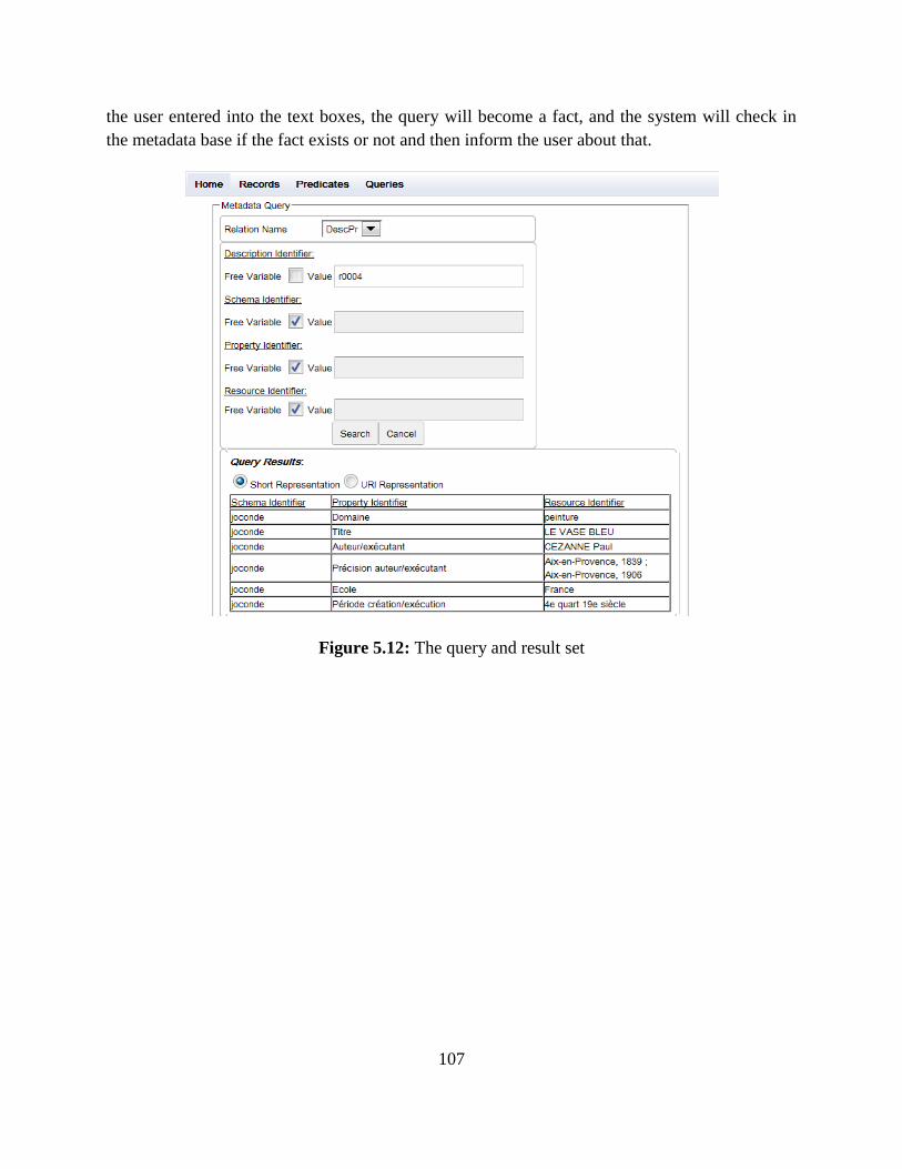
107
the user entered into the text boxes, the query will become a fact, and the system will check in
the metadata base if the fact exists or not and then inform the user about that.
Figure 5.12: The query and result set
108
Chapter 6
6 A contribution to content generation by reuse
Content generation by reuse is the process of creating, storing and reusing virtual composite
documents. These virtual documents then can be materialized so that they can be printed in the
paper format, if needed. All this work can be understood as developing a document management
system for our digital library. Therefore, our research team has developed a metadata
management model that will be used in metadata management part of virtual documents
[70][71]. In addition, some algorithms and software tools also need be studied and developed for
supporting the materialization of them.
This chapter presents our contribution to content generation by reuse. This is mostly theoretical
work done to complement the model and query language developed by our research team. Its
incorporation in the implemented system is left to future work.
This Chapter is organized as follows. Section 6.1 introduces some basic concepts such as content
reuse, document reuse and virtual document. Section 6.2 presents the algorithms for generation
of the table of contents and the index of virtual composite documents. Particularly, Section 6.2.1
provides some definitions of the table of contents and the index of composite documents; Section
6.2.2 defines a data structure used to describe nodes in a virtual document; Section 6.2.3 and
6.2.4 represent the algorithms for generation of the table of contents and the index in detail.
6.1 The basic concepts
6.1.1 Content reuse:
Content reuse is the practice of using existing content components to create new documents.
Although the majority of reusable content is text-based, any content can be reused (such as
graphics, charts, media).
Copying and pasting content can be seen as reuse but a big problem will occur when a reusable
content that appears in a lot of places has to be updated. We must spend a lot of time to find all
copy versions of the content and update them in the same way. This work also can result in
inconsistencies and inaccuracies if we have some mistakes in updating.
109
Content reuse means writing once and reusing it many times. Traditional documents are written
in files that consist of sections. Reusable content is written as objects or elements, not
documents. Documents are made up of content objects that can be mixed and matched to meet
specific information needs. Reusable content is broken down into smallest reusable objects
(sections, paragraphs, sentences). When information is broken down at this level it is easy to
select an element to reuse or repurpose it. However, even though content elements are re-used,
copying and pasting is eliminated. Instead, elements are stored in the database or Content
Management system and are referenced (pointed to) for inclusion in a virtual document. In this
way, the element can appear in multiple places, but reside in only one.
Content reuse has some advantages, as follows:
- Increased consistency: content is written once and reused many times, so it is consistent
everywhere it is used. Moreover, content written for reuse is more structured, and is
approached with a closer eye for a uniform writing style and branding.
- Reduced development and maintenance costs: the amount of content an author has to create
is reduced because the author can quickly have a needed content through management
facilities such as metadata and content management. In addition, when content is changed, it
also will be changed in everywhere that it is reused.
- Rapid reconfiguration: reusable content is modular content, so it helps organizations to
quickly reconfigure their content to meet changing needs. You can easily change the order of
modules, include new modules, exclude existing modules, and use modules to build entirely
new information products to meet new needs.
- Translation: content that need be translated run through the translation memory tool to
identify if content strings have been translated or not. If a content string has been translated,
the existing translation will be reused. As you plan for reuse, more contents can be reused,
and therefore translation costs are reduced even further.
There are two methods for reuse: opportunistic reuse and systematic reuse.
- Opportunistic reuse: the author makes a conscious decision to find an element, retrieve it
and reuse it. This is the most common form of reuse, but it absolutely depends to the
motivation of the author. Opportunistic reuse is rather similar to copy and paste but it’s
actually a pointer to the source content.
- Systematic reuse: systematic reuse is planned reuse. Specific content is identified as
reusable in a particular place and is automatically inserted. The author does not have to
determine whether the reusable content exists or search for and retrieve it; instead, we can
use a component content management system to do that. Because reuse can be planned and
110
ensured, systematic reuse can significantly increase the percentage of reuse, but it also
requires that content components be managed in a higher level of information architecture.
Within each method of reuse there are three options: locked reuse, derivative reuse and nested
reuse.
- Locked reuse: Locked reuse means reusable content cannot be changed by anyone except
by an author with appropriate permissions (original author). Locked reuse is useful when one
wants to ensure content is not changed.
- Derivative reuse: Derivative reuse means reusable content is not reused as is: the content is
changed. Normally, popular changes that may be made to the content are changes in tense,
spelling, order of the content, emphasis ... Derivative reuse is useful when one wants to retain
the relationships between pieces of information, but some of the content can be changed.
- Nested reuse: Nested reuse means content that includes a number of elements within a
single element. The sum of all the elements creates one element and subsets of the element
can be used to create alternate information products. Nested information reuse enables
authors to create content for all the outputs at the same time, thereby providing context and
frequently speeding up the content authoring process. Nested reuse is useful when one wants
to retain the context for alternate content or when content is a subset of other content.
Topics, sections, paragraphs, sentences, or even words can be reused. There are some types of
reuse, as follows:
- Topic-based reuse: reusable content components are individual topics that are pieces of
content about a specific subject, have an identifiable purpose, and can stand alone. Authors
assemble topics to create information products, and they can use maps for this job.
- Fragment-based reuse: pieces of a topic, like a paragraph or a section can also be reused. A
fragment can include a title as a topic, but can be a paragraph or even a sentence. We can use
some of the following methods for reusing a small piece of content: chunk out and save as an
individual piece/file of information (not good); use mark-up tags (XML) to mark as a piece
of information that we want to reuse, and so on.
While any element in any topic can be pointed to and identified for reuse, it makes more
sense to group together commonly reused content fragments into a single topic for ease of
search and retrieval.
- Filtered reuse: authors provide variants for a specific chunk of information in a single
component. The variations are identified by conditional tags or attributes. When the topic is
111
published, the different variations are published as required. Filtered reuse is often thought of
as conditional reuse.
Filtered reuse is usually used in multichannel publishing, audience variants, product variants,
region variants, … It’s also a way for authors to keep all variations together for ease of
writing and reviewing.
The creation of filtered reuse sometimes can be seen as ―building block‖ approach: There is a
core set of content that’s applicable in all uses and variant content that builds on the core
content that is only applicable in certain situations.
- Variable reuse: Variable reuse occurs when a variable is set up that can have a different
value in different situations. For example, the name of a product might be one thing in North
America and another in the European Union. Variable reuse becomes valuable when there
are only slight variations in content (such as product names in different regions), but
otherwise the rest of the content is identical.
The key to the successful reuse of content is to manage it at a granular level. These grains of
content (or components) can be shared, reviewed, updated, or combined and compiled into
different document aggregations and collections. Each component can be separately edited and
re-used, and workflow processes enforced. Content components can have their own lifecycles
and properties—version, owner, and approval—that support fine-grained reuse and the ability to
track such usage.
Granularity determines the smallest piece of information that is reusable. However for an
existing document, reuse may imply breaking it into smaller pieces. The level of granularity can
change throughout the content. In one instance, large sections may be reused unchanged; in
others, one may reuse content at the sentence or even the word level. Different levels of
granularity can be used for authoring, for reuse, and for delivery.
Making content ―re-usable‖ implies breaking it into smaller documents/components (―bursting‖),
putting these in a content repository instead of formatted files, and adding metadata to each
component for subsequent retrieval and use. As discussed above, the level of granularity is a key
decision, and this one has major impact on costs and effort: the more granular the content, the
greater the complexity of modeling, authoring and managing the content. Yet if content is not
granular enough, one can compromise the ability to reuse information. Regardless of the level of
granularity, however, authors still write complete documents, not elements. Authors write
documents and assign the required granularity to elements (as defined in the information model)
as they write. The main difference for authors is in following the assigned structure and in
assigning or selecting metadata. In essence, the granularity defines how the completed document
is broken down, tagged, and stored for reuse; but it does not define the authoring processes.
112
The management of content is based on metadata. Metadata is information about the data: e.g.
the instructions that come with the data. Metadata exists in addition to or after the data. It adds
context and a wider interpretation to the data. The metadata isn't the content. It exists apart from
the content [72]. Metadata is also a set of standards that groups agree to for information
definitions. Standards, which are the basis of any kind of data sharing, bring the possibility of
large-scale efficiencies in information interchange among groups that don't even know one
another. In the content management context, the standards may be mostly internal today, but they
serve the same purpose. Standards ensure that others can automatically reuse the efforts of one
person or group if they all follow the same standards [73].
To manage content, a choice must be made on what information must be separated out and made
into metadata and what remains part of the content. This distinction is a practical, not a
philosophical one. Managing content is managing metadata. Metadata provides the capability to
share data across applications. In a content management context, metadata enables publications
that need a somewhat different form of the same data to draw from a common repository [74].
Taxonomies are necessary to tag the documents created. The tagging (adding metadata) is
important to ensure that search engines will find the requested documents and for distribution
based on personalization rules. Tagging can be a labor-intense process, and requires the
cooperation of content authors. The capture of metadata should ideally occur right after content
creation through a combination of automatic (author, name, date, etc) and manual processes
(keywords, categories).
6.1.2 Document reuse
How to reuse documents, or pieces of document, is currently addressed in many ways and
multiple purposes. We propose a classification based on approaches originating from different
research areas. We distinguish between three main problems to be faced in this respect:
- How to add structure to existing documents? This is a matter of analysis;
- How to transform existing documents to reuse them within other applications? It ranges from
format transformations to more complex structure manipulations;
- How to design documents in such a way that facilitates their reuse by existing or further
applications? This is a ―document engineering‖ problem, very similar to design problems
addressed in the software engineering domain.
6.1.2.1 Structuring or re-structuring documents
It is commonly accepted that availability of structured documents greatly facilitates the reuse of
content. In this respect, a number of research works are dedicated to the analysis of raw or semi-
structured documents in order to structure or re-structure them in such a way that facilitate their
113
reuse through existing applications. In this respect, a lot of effort is dedicated to the analysis of
document images, either obtained by scanning operation or generated by applications, such as
Postscript files [75]. Another approach is adopted in MarkItUp [76], a system designed to
recognize the structure of untagged electronic documents; it is based on a learning by example
approach to gradually build recognition grammars. Extracting logical structure of library
references has been addressed by a mixed strategy combining image analysis and structural
information provided by the representation standard used (Unimarc). The system is based on a
constraint propagation method [77]. Finally, we may also cite work performed to interactively
restructuring HTML documents, an approach based on the use of a transformation language [78].
6.1.2.2 Transforming documents
Despite the obvious advantages conveyed by the manipulation of documents in a structured way,
reusing them within users’ environments raises a number of fundamental problems to transform
or to adapt their intrinsic structure:
- How to provide the users with appropriate editing operations (such as cut and paste
operations) that maintain the document consistency?
- How to merge documents conforming to different structures?
- How to guarantee the consistency of existing documents that relate to an evolving generic
structure?
- How to transform existing structured documents to reuse them in the framework of
applications relying on another document model?
The issue of structures transformations is complex. Depending on the context, several
approaches have been proposed or are currently under investigation to address this problem. An
interactive context (such as document editing) highly promotes the use of automatic
transformations that have to be performed in an efficient way to accommodate a required
response time [79]. Transforming existing structured documents in order to fit a different target
structure may be performed on the basis of explicit specification provided through descriptive
rules to guide the transformation process [82]. A combined approach has also been proposed to
take benefit from the two mentioned approaches [80][81].
6.1.2.3 Modeling modular structured documents
The formal descriptions of a document class aims at constraining the logical organisation of
document instances and thus guarantee their adequacy to a given model. Attributed grammars
have been originally used to define classes of document for publishing purposes. Initially, such
formal descriptions consisted in ―monolithic‖ descriptions, each of them, representing the
(logical) editorial structure of the document class. The need to build such descriptions in a
modular way, taking benefit from existing document fragment descriptions, has been rapidly
114
identified and addressed in different ways. Some document management systems explicitly
provide appropriate mechanisms to define reusable units of structured pieces of documents.
However, dealing with reusable fragments of documents raises problems, very similar to those
encountered in the software engineering domain, that are not currently solved. Ongoing research
works have mostly adopted an object-oriented design for the appropriate representation of
documents models [83][84]. This approach is relevant in many respects. It allows the precise
definition of pieces of information as well as the processing operations to be performed on
identified structured data. It aims at facilitating the exchange and reuse of document fragments
between heterogeneous applications.
6.1.3 Virtual Documents
Reusing information implies that there exists a mechanism to combine (or compose) the
available pieces of information into new documents derived according to the users’ needs. Two
major issues have to be addressed to reach this objective: how to model pieces of information
and how to provide methods for assembling such pieces in a consistent way?
6.1.3.1 Dynamic Document Fragment
Much work has been done in order to offer repositories of documents in order to reuse them.
However, the majority of works emphasized on documents collection, documents identification
and documents access. The integration of those fragments when authoring new documents,
especially in the case of structured documents is not yet answered in a totally satisfactory way. In
addition, the majority of works focused on documents content reuse. The reuse of document
content, structure and behavior remains an open problem.
The first concept that seems for us a major concept for document reuse is what we call ―Dynamic
Structured Document Fragment‖. We consider the document fragment as an independent, self-
described piece of information that can be reused and adapts to new documents. The definition of
a dynamic structured fragment includes several aspects:
- the definition of the granularity of such reusable fragments
- the definition of a fragment content model
- the definition of fragment metadata, to characterize and identify it within an authoring
process,
- the definition of a mechanism to associate methods to describe the fragment interface and
behavior.
In our approach ―reusing‖ consists in integrating both the structured content of the fragment and
the associated methods, in order to enhance processing operations on the fragment. The fragment
115
can be manipulated separately with appropriate authoring tools, or within a more general context
by applications that manipulate the newly created document.
6.1.3.2 Virtual Document
Digital libraries often generate documents and screens dynamically in response to user searches.
Furthermore, many animations and simulations stored in educational resource repositories
generate documents and displays based on parameters that users input. Such ―virtual documents‖
only exist when the user visits them. When the user closes the window, these virtual artifacts are
gone.
Virtual documents require an entirely new level of ―just-in-time‖ hypermedia support. When
traversing links to them, they need to be regenerated. Regeneration requires the hypermedia
system to recognize (―re-identify‖) them to place (―re-locate‖) link anchors, even if their contents
have shifted (and thus their overall appearance has changed). When elements from one virtual
document appear as components within another, the hypermedia system needs to re-identify the
elements and to re-locate anchors within them.
The virtual document model will precisely define how to derive each virtual document from the
stored document fragments. The specification of a virtual document will contain at least:
- A selection specification, which determines which fragments to use; it is a set of queries on
the fragment repository (based either on fragment content or meta-content).
- A global document structure, which can be either static (fixed in the specification) or
dynamic (computed on the document fragments, e.g. links obtained by computing a semantic
proximity between two fragments); global structures may take various forms, such as
sequences, trees, graphs, etc.
- A presentation specification, which indicates how to represent the global structure (for
instance, a tree can be represented graphically, with embedded boxes, linearly with
parentheses, etc.)
- Fragment operations: they specify which operation (method) to apply on each fragment (e.g.
a fragment representing a formula may be expressed in a given system of units, a picture may
be resized or rotated, etc.)
- Inheritance relationships: a specification may be derived from one or more other
specifications (this is particularly useful to adapt existing specifications to new needs)
A virtual document is a document for which no persistent state exists and for which some or all
of its instances are generated at run time. Watters and Shepherd [85] present a number of
interesting research issues about virtual documents, including:
116
• Reference: How do you reference a virtual document? Does the reference refer to the process of
generation, the parameters and process together, or a particular instance of a generated
document? These last two may be different if, in fact some dynamic part of the document is not
dynamic because of the parameters (rather, for example, such as something that depends on the
time of viewing).
• Generation: A virtual document can be defined by an author through the use of templates and
links, or it can be defined as the result of a search or other application. Ranwez and Crampes [86]
define virtual documents as a non-organized collection of Information Bricks (IB), associated
with methods allowing the generation of a finished IB sequence. For our research we will mainly
be considering virtual documents that are created by an application as the result of a user search
or query.
• Revisiting: Users expect that documents found once will be available on a subsequent search.
The notion of a book-mark does not apply to virtual documents in a normal, retrieval sense.
Bookmarks for virtual documents need enough information to recreate the document as it was.
• Versioning: What does it mean to ―version‖ a virtual document? Are you versioning the
generation process, or storing generated pages over time? Some systems such as WikiWeb [87]
visit a URL and store page differences in a database, so that the system can track the Web page
modifications.
Some research has been conducted on these issues. Caumanns [88] deals with the creation of
dynamic documents by predefined templates or knowledge. Iksal and Garlatti [89] describe an
adaptive web application system, which generates adaptive virtual documents by means of a
semantic composition engine based on user models. Tetchueng et al. [90] develop an adaptive
composition engine, called SCARCE—Semantic and Adaptive Retrieval and Composition
Engine—to design a context-aware learning system for an adaptive virtual document. Qu et al.
[91] use the RDF graph model to define description formulations and neighboring operations for
constructing virtual documents. Meanwhile, Li Zhang et al. [92] consider virtual documents
created by digital libraries and analytic applications, where the hypermedia middleware system
itself has no way to control their content or generation, but must determine that a regenerated
document is the same one as before.
6.2 Generating the table of contents and the index of virtual
composite documents
A user creates a new document either from scratch or by editing and re-using existing
documents; in the first case the document is called atomic whereas in the second composite. In
our approach, we assume that a composite document has a tree structure, in which each interior
117
node is a composite document and each leaf node is an atomic document; moreover, each node
(whether interior or leaf) has a description of the content it represents. A composite document is
a virtual document in that it simply describes the content of the component documents and the
way they are structured to make up the composite document.
In this context, we discuss how to design and implement an interface, together with algorithms
and software tools, allowing the user of a digital library to:
1/ Select a set of n digital documents from the library and/or his desktop, say
<dd1, descr1>, <dd2, descr2>, …, <ddn, descrn>
where ddi is the document identifier, and descri is the document description (i.e. a set of terms
from a taxonomy).
2/ Structure the documents in a hierarchy with the composite document <dd, descr> as root
3/ Infer the composite document description descr from the descriptions descr1, descr2, …, descrn
of the component documents
4/ Generate the table of contents and the index of the composite document
5/ Store the composite document <dd, descr> in the digital library
6/ Materialize the composite document at will (i.e. produce a ―paper version‖ of it)
Note that, two materializations at two different points in time may produce different paper
versions, reflecting possible changes in the component documents during the time elapsed.
In this section, we present algorithms that help to generate the table of contents and the index of
a virtual composite document. Our algorithms describe how one can derive a ―paper version‖ of
a virtual composite document, a process that we call ―materialization‖ of the virtual composite
document. Before entering into the details of our algorithms, we would like to discuss the main
concepts about materialization of a virtual composite document as well the table of contents and
the index of it.
6.2.1 The table of contents and the index of composite documents
To begin with, we assume that a user uses a graphical user interface to create a new composite
document based on the model proposed in the previous section. The user first performs some
drag-and drop operations to create the structure of the composite document from atomic
documents existing in the system. Note that in this step, the user only determines the parent-child
relationship between nodes and ignores the ordering of parts in the composite document. Then,
he adds the descriptions to all nodes in the composite document based on the suggestions of the
118
system as described in [70][71]. Alternatively, he can add the descriptions to a node on his own
initiative by using key words from a taxonomy.
When the user finishes his work, a new composite document is created and it consists of many
nodes that are structured in hierarchical tree form. These nodes represent identifiers (for example
URIs). By clicking on a node we can access the identified resource. Then, the composite
document is stored in the digital library for future use. Otherwise, the user can carries out next
operations to materialize the virtual document.
6.2.1.1 Materialization of virtual composite documents
Materialization simply puts the contents that can be accessed through the nodes in a sequence
(i.e. in a linear order). This work will produce a usual document, a paper version of virtual
composite document that is printable. To facilitate of the assembly of all contents of nodes in a
unique textbook, we assume that all nodes in the system that can be used to create a
materializable virtual document are in the same pre-defined format.
Therefore, what is important for the materialization of a virtual document is that someone must
input the linear order of nodes. This can be done by showing to the user all the nodes, level by
level, and asking the user to mark (for each level) the desired linear order of nodes. Note that, if
we materialize the virtual document at different time points we obtain (possibly) different
materializations, reflecting possible changes in the component documents during the time
elapsed.
Another important issue of the materialization of a virtual composite document is that we must
offer a table of contents and an index of the virtual document at the time it is materialized. Both
of them can be derived from the virtual composite document and the linear order of nodes in the
virtual document that the user can input at materialization time.
6.2.1.2 Definitions of the table of contents and the index of composite documents
Traditionally, a typical table of contents lists topics described in the book and provides
information about their location in the book. The hierarchical organization of information in the
table further refines information access by specifying the relations between different topics and
providing rich contextual information during browsing. Meanwhile, an index is a thoughtful list
of words and topics taken from the text of the book. Written in alphabetical order, and organized
so that it also reflects sub-topics, the index gives you an idea of the book’s subject matter. Each
word is followed by the page or multiple page numbers of every instance the word (or topic)
appears in a meaningful context.
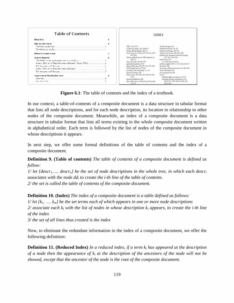
119
Figure 6.1: The table of contents and the index of a textbook.
In our context, a table-of-contents of a composite document is a data structure in tabular format
that lists all node descriptions, and for each node description, its location in relationship to other
nodes of the composite document. Meanwhile, an index of a composite document is a data
structure in tabular format that lists all terms existing in the whole composite document written
in alphabetical order. Each term is followed by the list of nodes of the composite document in
whose descriptions it appears.
In next step, we offer some formal definitions of the table of contents and the index of a
composite document.
Definition 9. (Table of contents) The table of contents of a composite document is defined as
follow:
1/ let {descr1,…, descrn} be the set of node descriptions in the whole tree, in which each descri
associates with the node ddi to create the i-th line of the table of contents.
2/ the set is called the table of contents of the composite document.
Definition 10. (Index) The index of a composite document is a table defined as follows:
1/ let {k1, …, km} be the set terms each of which appears in one or more node descriptions
2/ associate each ki with the list of nodes in whose description ki appears, to create the i-th line
of the index
3/ the set of all lines thus created is the index
Now, to eliminate the redundant information in the index of a composite document, we offer the
following definition:
Definition 11. (Reduced Index) In a reduced index, if a term ki has appeared at the description
of a node then the appearance of ki at the description of the ancestors of the node will not be
showed, except that the ancestor of the node is the root of the composite document.
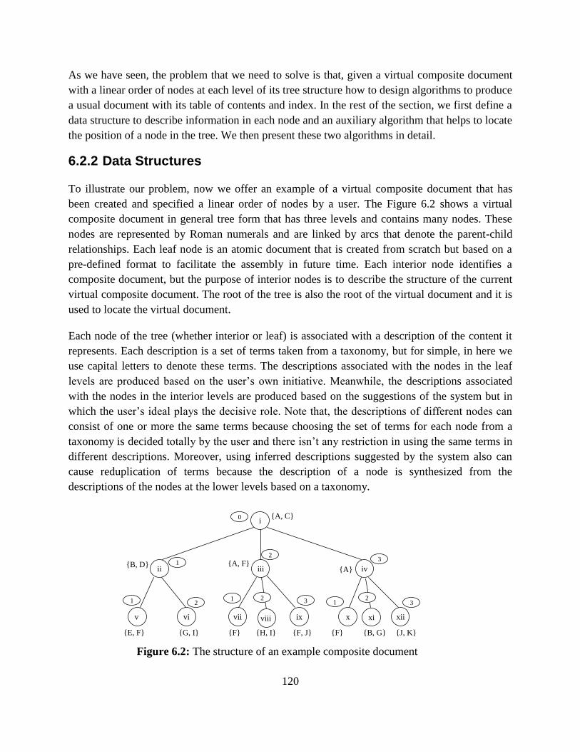
120
As we have seen, the problem that we need to solve is that, given a virtual composite document
with a linear order of nodes at each level of its tree structure how to design algorithms to produce
a usual document with its table of contents and index. In the rest of the section, we first define a
data structure to describe information in each node and an auxiliary algorithm that helps to locate
the position of a node in the tree. We then present these two algorithms in detail.
6.2.2 Data Structures
To illustrate our problem, now we offer an example of a virtual composite document that has
been created and specified a linear order of nodes by a user. The Figure 6.2 shows a virtual
composite document in general tree form that has three levels and contains many nodes. These
nodes are represented by Roman numerals and are linked by arcs that denote the parent-child
relationships. Each leaf node is an atomic document that is created from scratch but based on a
pre-defined format to facilitate the assembly in future time. Each interior node identifies a
composite document, but the purpose of interior nodes is to describe the structure of the current
virtual composite document. The root of the tree is also the root of the virtual document and it is
used to locate the virtual document.
Each node of the tree (whether interior or leaf) is associated with a description of the content it
represents. Each description is a set of terms taken from a taxonomy, but for simple, in here we
use capital letters to denote these terms. The descriptions associated with the nodes in the leaf
levels are produced based on the user’s own initiative. Meanwhile, the descriptions associated
with the nodes in the interior levels are produced based on the suggestions of the system but in
which the user’s ideal plays the decisive role. Note that, the descriptions of different nodes can
consist of one or more the same terms because choosing the set of terms for each node from a
taxonomy is decided totally by the user and there isn’t any restriction in using the same terms in
different descriptions. Moreover, using inferred descriptions suggested by the system also can
cause reduplication of terms because the description of a node is synthesized from the
descriptions of the nodes at the lower levels based on a taxonomy.
Figure 6.2: The structure of an example composite document
i
iii ii
vii x
iv
ix v vi xii
{A, C}
{B, D} {A}
{A, F}
{E, F} {G, I}
xi viii
{F} {H, I} {F, J} {F} {B, G} {J, K}
0
1
2
3 2
1 1 2 3 1 2
3
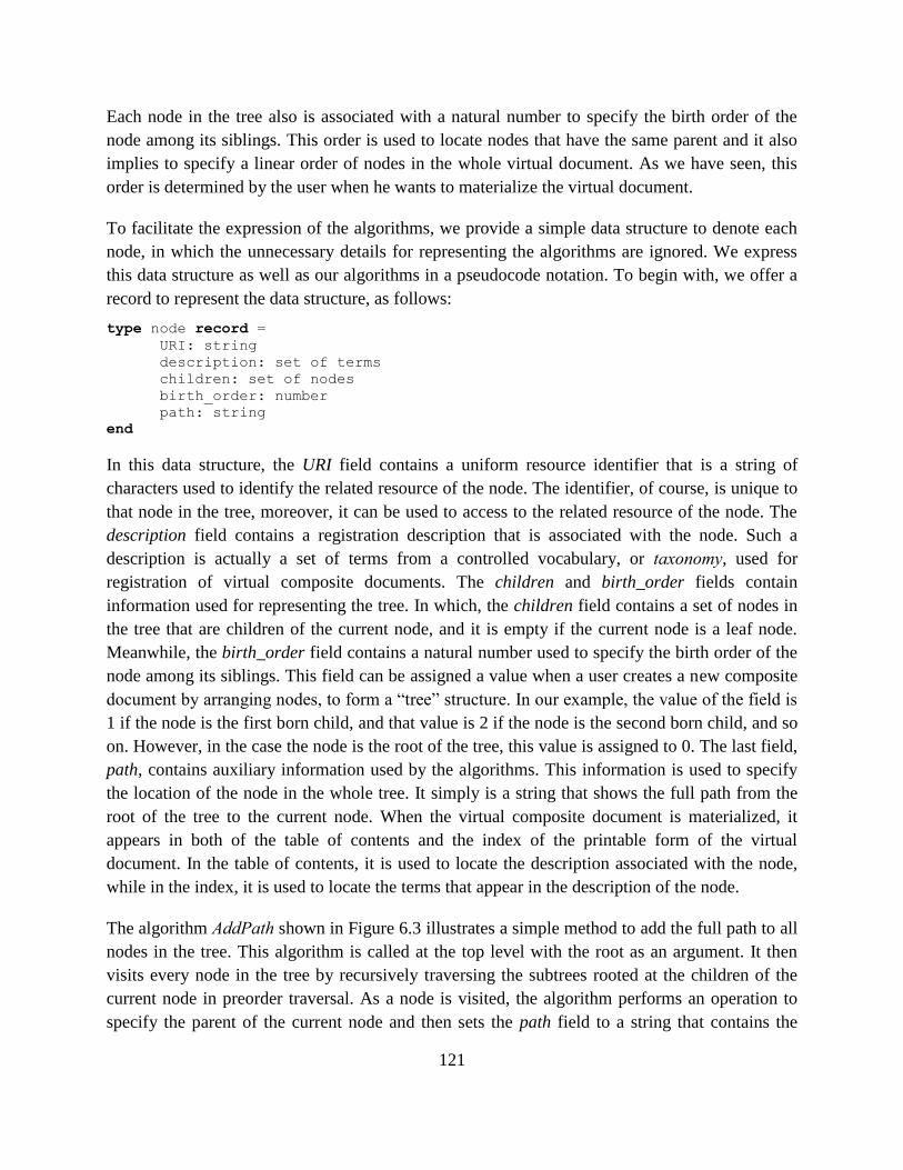
121
Each node in the tree also is associated with a natural number to specify the birth order of the
node among its siblings. This order is used to locate nodes that have the same parent and it also
implies to specify a linear order of nodes in the whole virtual document. As we have seen, this
order is determined by the user when he wants to materialize the virtual document.
To facilitate the expression of the algorithms, we provide a simple data structure to denote each
node, in which the unnecessary details for representing the algorithms are ignored. We express
this data structure as well as our algorithms in a pseudocode notation. To begin with, we offer a
record to represent the data structure, as follows:
type node record =
URI: string
description: set of terms
children: set of nodes
birth_order: number
path: string
end
In this data structure, the URI field contains a uniform resource identifier that is a string of
characters used to identify the related resource of the node. The identifier, of course, is unique to
that node in the tree, moreover, it can be used to access to the related resource of the node. The
description field contains a registration description that is associated with the node. Such a
description is actually a set of terms from a controlled vocabulary, or taxonomy, used for
registration of virtual composite documents. The children and birth_order fields contain
information used for representing the tree. In which, the children field contains a set of nodes in
the tree that are children of the current node, and it is empty if the current node is a leaf node.
Meanwhile, the birth_order field contains a natural number used to specify the birth order of the
node among its siblings. This field can be assigned a value when a user creates a new composite
document by arranging nodes, to form a ―tree‖ structure. In our example, the value of the field is
1 if the node is the first born child, and that value is 2 if the node is the second born child, and so
on. However, in the case the node is the root of the tree, this value is assigned to 0. The last field,
path, contains auxiliary information used by the algorithms. This information is used to specify
the location of the node in the whole tree. It simply is a string that shows the full path from the
root of the tree to the current node. When the virtual composite document is materialized, it
appears in both of the table of contents and the index of the printable form of the virtual
document. In the table of contents, it is used to locate the description associated with the node,
while in the index, it is used to locate the terms that appear in the description of the node.
The algorithm AddPath shown in Figure 6.3 illustrates a simple method to add the full path to all
nodes in the tree. This algorithm is called at the top level with the root as an argument. It then
visits every node in the tree by recursively traversing the subtrees rooted at the children of the
current node in preorder traversal. As a node is visited, the algorithm performs an operation to
specify the parent of the current node and then sets the path field to a string that contains the
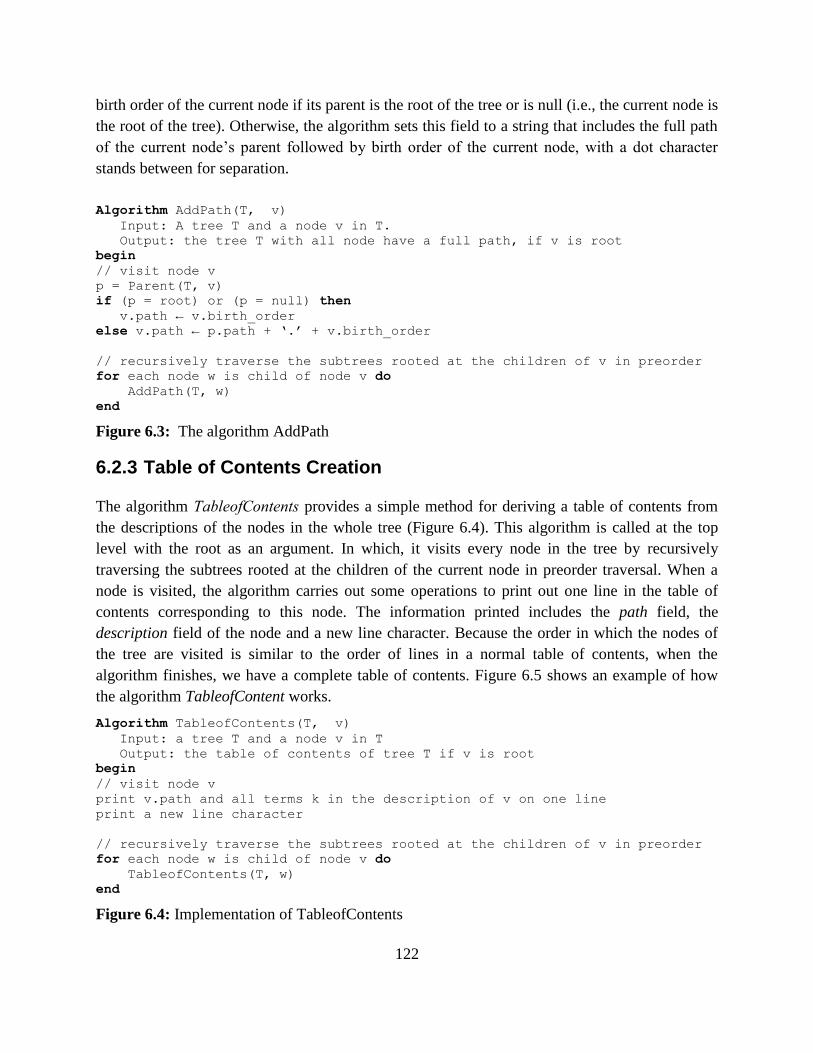
122
birth order of the current node if its parent is the root of the tree or is null (i.e., the current node is
the root of the tree). Otherwise, the algorithm sets this field to a string that includes the full path
of the current node’s parent followed by birth order of the current node, with a dot character
stands between for separation.
Algorithm AddPath(T, v)
Input: A tree T and a node v in T.
Output: the tree T with all node have a full path, if v is root
begin
// visit node v
p = Parent(T, v)
if (p = root) or (p = null) then
v.path ← v.birth_order
else v.path ← p.path + ‘.’ + v.birth_order
// recursively traverse the subtrees rooted at the children of v in preorder
for each node w is child of node v do
AddPath(T, w)
end
Figure 6.3: The algorithm AddPath
6.2.3 Table of Contents Creation
The algorithm TableofContents provides a simple method for deriving a table of contents from
the descriptions of the nodes in the whole tree (Figure 6.4). This algorithm is called at the top
level with the root as an argument. In which, it visits every node in the tree by recursively
traversing the subtrees rooted at the children of the current node in preorder traversal. When a
node is visited, the algorithm carries out some operations to print out one line in the table of
contents corresponding to this node. The information printed includes the path field, the
description field of the node and a new line character. Because the order in which the nodes of
the tree are visited is similar to the order of lines in a normal table of contents, when the
algorithm finishes, we have a complete table of contents. Figure 6.5 shows an example of how
the algorithm TableofContent works.
Algorithm TableofContents(T, v)
Input: a tree T and a node v in T
Output: the table of contents of tree T if v is root
begin
// visit node v
print v.path and all terms k in the description of v on one line
print a new line character
// recursively traverse the subtrees rooted at the children of v in preorder
for each node w is child of node v do
TableofContents(T, w)
end
Figure 6.4: Implementation of TableofContents
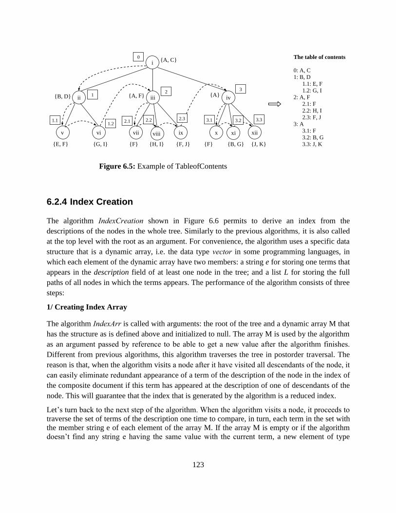
123
Figure 6.5: Example of TableofContents
6.2.4 Index Creation
The algorithm IndexCreation shown in Figure 6.6 permits to derive an index from the
descriptions of the nodes in the whole tree. Similarly to the previous algorithms, it is also called
at the top level with the root as an argument. For convenience, the algorithm uses a specific data
structure that is a dynamic array, i.e. the data type vector in some programming languages, in
which each element of the dynamic array have two members: a string e for storing one terms that
appears in the description field of at least one node in the tree; and a list L for storing the full
paths of all nodes in which the terms appears. The performance of the algorithm consists of three
steps:
1/ Creating Index Array
The algorithm IndexArr is called with arguments: the root of the tree and a dynamic array M that
has the structure as is defined above and initialized to null. The array M is used by the algorithm
as an argument passed by reference to be able to get a new value after the algorithm finishes.
Different from previous algorithms, this algorithm traverses the tree in postorder traversal. The
reason is that, when the algorithm visits a node after it have visited all descendants of the node, it
can easily eliminate redundant appearance of a term of the description of the node in the index of
the composite document if this term has appeared at the description of one of descendants of the
node. This will guarantee that the index that is generated by the algorithm is a reduced index.
Let’s turn back to the next step of the algorithm. When the algorithm visits a node, it proceeds to
traverse the set of terms of the description one time to compare, in turn, each term in the set with
the member string e of each element of the array M. If the array M is empty or if the algorithm
doesn’t find any string e having the same value with the current term, a new element of type
i
iii ii
vii x
iv
ix v vi xii
{A, C}
{B, D} {A} {A, F}
{E, F} {G, I}
xi viii
{F} {H, I} {F, J} {F} {B, G} {J, K}
0
1 3
2
1.1 1.2
2.1 2.2 2.3 3.1 3.2 3.3
The table of contents
0: A, C
1: B, D
1.1: E, F
1.2: G, I
2: A, F
2.1: F
2.2: H, I
2.3: F, J
3: A
3.1: F
3.2: B, G
3.3: J, K
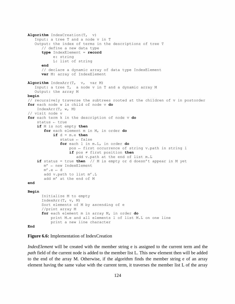
124
Algorithm IndexCreation(T, v)
Input: a tree T and a node v in T
Output: the index of terms in the descriptions of tree T
// define a new data type
type IndexElement = record
e: string
L: list of string
end
// declare a dynamic array of data type IndexElement
var M: array of IndexElement
Algorithm IndexArr(T, v, var M)
Input: a tree T, a node v in T and a dynamic array M
Output: the array M
begin
// recursively traverse the subtrees rooted at the children of v in postorder
for each node w is child of node v do
IndexArr(T, w, M)
// visit node v
for each term k in the description of node v do
status ← true
if M is not empty then
for each element m in M, in order do
if d = m.e then
status ← false
for each l in m.L, in order do
pos ← first occurrence of string v.path in string l
if pos ≠ first position then
add v.path at the end of list m.L
if status = true then // M is empty or d doesn’t appear in M yet
m’ ← new IndexElement
m’.e ← d
add v.path to list m’.L
add m’ at the end of M
end
Begin
Initialize M to empty
IndexArr(T, v, M)
Sort elements of M by ascending of e
//print array M
for each element m in array M, in order do
print M.e and all elements l of list M.L on one line
print a new line character
End
Figure 6.6: Implementation of IndexCreation
IndexElement will be created with the member string e is assigned to the current term and the
path field of the current node is added to the member list L. This new element then will be added
to the end of the array M. Otherwise, if the algorithm finds the member string e of an array
element having the same value with the current term, it traverses the member list L of the array
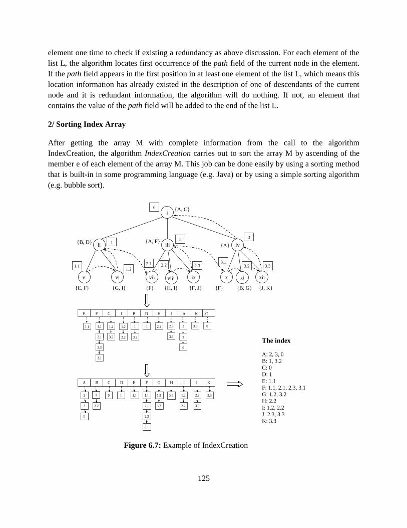
125
element one time to check if existing a redundancy as above discussion. For each element of the
list L, the algorithm locates first occurrence of the path field of the current node in the element.
If the path field appears in the first position in at least one element of the list L, which means this
location information has already existed in the description of one of descendants of the current
node and it is redundant information, the algorithm will do nothing. If not, an element that
contains the value of the path field will be added to the end of the list L.
2/ Sorting Index Array
After getting the array M with complete information from the call to the algorithm
IndexCreation, the algorithm IndexCreation carries out to sort the array M by ascending of the
member e of each element of the array M. This job can be done easily by using a sorting method
that is built-in in some programming language (e.g. Java) or by using a simple sorting algorithm
(e.g. bubble sort).
Figure 6.7: Example of IndexCreation
i
iii ii
vii x
iv
ix v vi xii
{A, C}
{B, D} {A}
{A, F}
{E, F} {G, I}
xi viii
{F} {H, I} {F, J} {F} {B, G} {J, K}
0
1 3
2
1.1 1.2
2.1 2.2 2.3 3.1
3.2 3.3
1.1
2.1
2.3
1.2
2.2
3.3 1.2
3.2
1.1 2.2 1 1 2.3
3.3
2 0
3.2
3.1
3
0
E F G I B D H J A K C
The index
A: 2, 3, 0
B: 1, 3.2
C: 0
D: 1
E: 1.1
F: 1.1, 2.1, 2.3, 3.1
G: 1.2, 3.2
H: 2.2
I: 1.2, 2.2
J: 2.3, 3.3
K: 3.3
1.1
2.1
2.3
1.2
2.2
3.3 1.2
3.2
1.1 2.2 1 1 2.3
3.3
2 0
3.2
3.1
3
0
A B C D E F G H I J K
126
3/ Printing Index Array
In the final step, the algorithm performs some operations to print out the index by traversing the
array M one time. For each element of the array M, the algorithm prints out one line in the index.
The information printed includes the member e, all elements of the member list L and a new line
character.
Figure 6.7 shows an example of how the algorithm IndexCreation works. Firstly, It creates an
index array while traverses the tree in postorder traversal. The index array then is sorted by
ascending of the terms in each element. At the end, the algorithm prints out a complete index.
We have presented some algorithms for generation of the table of contents and the index of
virtual composite documents. These algorithms will be implemented by the system to support for
the materialization of a virtual document. Since the focus of our work is on the generation aspect
of table-of-contents and index constructions, we assume that atomic documents, leaf nodes,
provided is in the same format and they can be assembled together easily without any mismatch.
Therefore, to facilitate the solution of this problem, we need define a unique format for all
atomic documents that can be reused in our system. A proposal is that we can define them in a
XML format if their contents are text-based. However, we must find some other solutions in
cases if their contents are in any formats (such as graphics, charts, media).
Another important issue need be considered is that, we must specify the format of usual
documents that are the results of the materialization. A proposal is that these documents are
created in EPUB format. EPUB (short for electronic publication) is open e-book standard by the
International Digital Publishing Forum (IDPF)1. It supersedes the Open eBook standard and its
files have the extension .epub.
1 The International Digital Publishing Forum (IDPF). idpf.org/epub
127
Chapter 7
7 Conclusions and Future Work
In this Chapter, we conclude the thesis and give remarks for future work. Particularly, we discuss
some results that we gained in the implementation of the data model for digital libraries. We then
mention some difficulties in the implementation process that we must overcome in the future.
Finally, we propose some possible extensions of our current work.
This Chapter is organized as follows. Section 7.1 gives concluding remarks. Section 7.2
considers the extension of the current work and gives a future research agenda.
7.1 Conclusions
Inspired by the architecture of the Web, our research team has developed a data model for digital
libraries based on three basic concepts: identifier, resource and description. Identifiers uniquely
denote resources, and descriptions describe properties of resources. The three basic concepts of
our model parallel the fundamental concepts of the Web architecture, which are: URI, resource
and representation.
The model generalizes the Web architecture in three different directions:
(a) the set of identifiers isn’t fixed a priori,
(b) the set of identifiers changes dynamically over time, and
(c) a description may include not only representations of a resource, but also other properties.
Additionally, in the model, descriptions are defined independently of the resources they might be
associated to, whereas in the Web there is a strict dependence between a resource and its
representations. Although in the Web architecture nothing forbids to use the representation of a
resource also as a representation for another resource, this functionality is not explicit in the
Web.
In the model, the relations are used to express the basic facts stored in a digital library, and the
model is formalized as a first-order theory. The axioms of the theory give the formal semantics
of the notions of the model, and at the same time, provide a definition of the knowledge that is
128
implicit in a digital library. The theory is then translated into a datalog program that, given a
digital library, allows completing the digital library with the knowledge implicit in it.
To demonstrate the suitability of the model for practical applications, we provide a full
translation of the model to RDF and of the query language to SPARQL. In addition, we
introduce the RDFDL vocabulary, which extends the vocabulary of RDFS with four new
symbols that are necessary to translate a digital library in RDF.
To show the feasibility of the theoretical model, we have designed and implemented a prototype
that is a simplified form of the model and query language. Built as a web application, the system
adopts GWT, the Google Web Toolkit framework which facilitates the development of web
applications as desktop applications, performing business logic operations on server side, as well
as on client side. The Client Side logic operates within the web browser running on a user’s local
computer, while the Server Side logic operates on the web server hosting the application.
Our application basically is used to facilitate the creation, retrieval, update and deletion of
predicates by content providers and to provide to end users basic services for evaluating
conjunctive queries. Its main functionality includes the following operations:
- Create/delete/update/view predicates
- Query metadata in the metadata base
- Create/delete/update/manage Users
During the thesis work, the system was built, tested, and debugged locally and then deployed on
Google App Engine (GAE). In the future, it can be expanded to become a full fledged digital
library management system.
7.2 Future Work
In our current system, we have installed the algorithms to support conjunctive queries. However,
the current user interface of our prototype only allows users to perform atomic queries.
Designing an interface that supports fully conjunctive queries is fairly complex and requires
some efforts, because, based on the theoretical model, the number of atomic queries that are
components of a conjunctive query is unlimited. In the future, we will try to improve the current
user interface so that it supports the performance of conjunctive queries. Some suggestions for
the design of the user interface in the future are: (a) only display fields of new atomic query that
is a component of the conjunctive query on the interface when the user asks to add the atomic
query; and (b) offer a limit on the number of atomic queries that can be displayed on the
interface.
129
In our current system, to handle the facts in the metadata base, we permit all of them to display
on the user interface. Then the users can choose one or more facts to perform some desired
operations on them. However, when the number of facts in the metadata base is big, this solution
is unfeasible. In the future, we will improve the system so that it supports the search for
knowledge on various criteria. The number of facts displayed on the user interface in the future
will reduce measurable, so users can manipulate them more effectively.
Our current system only supports some specific schemata, for example, the schema joconde. The
problem here is that each schema has a particular way to express its identifiers, as well as a
particular way to convert between the original form and URI form of its identifiers. This is
defined by each organization which is the owner of the resources and there is no standard that we
can use to formulate it. Therefore, in order for the system to support a new schema, we must
describe the type of its identifiers and the way to convert between two forms of these identifiers.
In the future, our system will support many schemata and provide a user interface that allows
users to handle these schemata. With the user interface, the users can perform some operations
on schemata, such as adding a new schema, together with a description about its type of
identifiers and the way to convert between two forms of these identifiers. Moreover, the users
can also edit or delete an existing schema in the system.
In our implementation we have used URIs as identifiers and therefore we have no consistency
problem. However, if we want to use digital objects in general as identifiers we will have to
design algorithms for checking the consistency of the digital library during updates.
Another aspect of our implementation that needs further work is completeness. A digital library
is complete if its metadata base satisfies three basic requirements, as follows: it includes all
knowledge explicitly given by users; it satisfies all axioms of the model; and it does not include
any other knowledge apart from the knowledge satisfying the previous two conditions. To ensure
the completeness of a digital library, we must implement an inference engine that supports all
axioms of the model and allows the system to generate new knowledge based on the axioms and
all existing knowledge in the digital library.
Traditionally, the inference engine is the core of an expert system and acts as the generic control
mechanism that applies the axiomatic knowledge from the knowledge base to the task-specific
data to reach some conclusion. In simple rule-based systems, there are two kinds of inference,
forward and backward chaining. Forward chaining is a top-down method which takes facts as
they become available and attempts to draw conclusions (from satisfied conditions in rules)
which lead to actions being executed. Backward chaining is the reverse. It is a bottom-up
procedure which starts with goals (or actions) and queries the user about information which may
satisfy the conditions contained in the rules. It is a verification process rather than an exploration
process.
130
In fact, inference capabilities are not built in to RDF, but the uniform structure and formal
semantics of RDF provide a basis for generalized inference. Therefore, some general-purpose
tools have been developed to be able to combine and augment RDF information. They are
inference engines designed to better adapt to the semantic web, so we call them ―RDF inference
engines‖. Some typical examples of such tools are listed below:
Closed World Machine (cwm)1: A data manipulator, rules processor, and query system
mostly using the Notation 3 textual RDF syntax.
Euler2: An inference engine supporting logic-based proofs. It is a backward-chaining
reasoner enhanced with Euler path detection.
Sesame3: An open source RDF database with support for RDF Schema inferencing and
querying.
Jena4: a Java framework for semantic web applications which also includes rule-based
inference engines.
In the future, we consider the ability for integration of such a tool into the our system, so that our
system can support the creation of a correct rule base on top of its triple store, and further can
ensure the completeness of the digital library.
Finally, one important extension of our current work is content generation by reuse as described
in Chapter 6. We recall that composable resources are information fragments that can be reused.
They can be one chapter of a book or one painting in an exhibition. Users can combine some of
them together to form a new resource by providing a structure to combine them that we call a
virtual document. This means that our future system can be considered as a digital library of
virtual documents.
In our approach, a virtual document is a set of information fragments associated with filtering,
organization and assembling mechanisms. Depending on a user profile or user intensions, these
mechanisms will produce different documents adapted to the user needs. The ability to select and
assemble informational fragments coming from various virtual documents opens new
perspectives on the reading action, but it also raises important questions that we need to spend
more time and efforts to find the answers. In a digital library of virtual documents, a document
reading system should be able to compose new documents from all the available informational
fragments of the library, according to the readers’ objectives. It is also necessary to check the
semantic compatibility of the fragments before re-using them. The objective is to deliver the
reader new documents that are semantically coherent.
1 Cwm. www.w3.org/2000/10/swap/doc/cwm
2 Euler. www.agfa.com/w3c/euler/
3 Sesame. www.openrdf.org
4 Apache Jena. jena.apache.org/
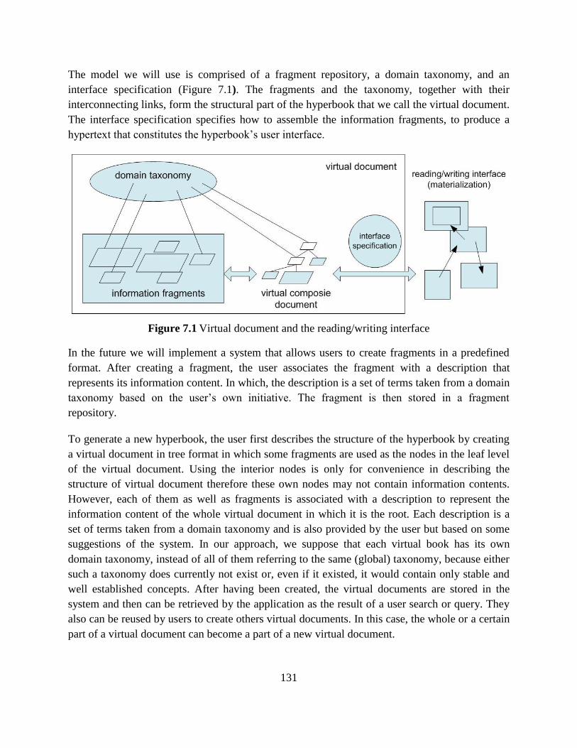
131
The model we will use is comprised of a fragment repository, a domain taxonomy, and an
interface specification (Figure 7.1). The fragments and the taxonomy, together with their
interconnecting links, form the structural part of the hyperbook that we call the virtual document.
The interface specification specifies how to assemble the information fragments, to produce a
hypertext that constitutes the hyperbook’s user interface.
Figure 7.1 Virtual document and the reading/writing interface
In the future we will implement a system that allows users to create fragments in a predefined
format. After creating a fragment, the user associates the fragment with a description that
represents its information content. In which, the description is a set of terms taken from a domain
taxonomy based on the user’s own initiative. The fragment is then stored in a fragment
repository.
To generate a new hyperbook, the user first describes the structure of the hyperbook by creating
a virtual document in tree format in which some fragments are used as the nodes in the leaf level
of the virtual document. Using the interior nodes is only for convenience in describing the
structure of virtual document therefore these own nodes may not contain information contents.
However, each of them as well as fragments is associated with a description to represent the
information content of the whole virtual document in which it is the root. Each description is a
set of terms taken from a domain taxonomy and is also provided by the user but based on some
suggestions of the system. In our approach, we suppose that each virtual book has its own
domain taxonomy, instead of all of them referring to the same (global) taxonomy, because either
such a taxonomy does currently not exist or, even if it existed, it would contain only stable and
well established concepts. After having been created, the virtual documents are stored in the
system and then can be retrieved by the application as the result of a user search or query. They
also can be reused by users to create others virtual documents. In this case, the whole or a certain
part of a virtual document can become a part of a new virtual document.
132
In the next step, to create the hyperbook’s user interface, the system must provide its virtual
document an interface specification based on the information provided by the user. One of the
key matters is that the user must input the linear order of nodes in the virtual document. Basing
on the interface specification, the fragments of the virtual document are assembled and then are
displayed on the reading/writing interfaces. The system also supports generating the table of
contents and the index of the hyperbook based on the descriptions of the nodes of its virtual
document. This also facilitates the generation of a complete usual document, a paper version of
the hyperbook, if needed.
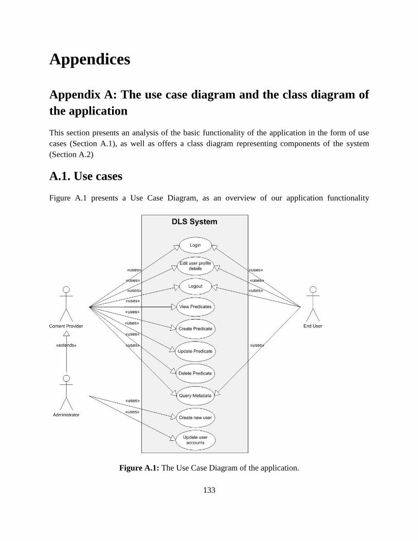
133
Appendices
Appendix A: The use case diagram and the class diagram of
the application
This section presents an analysis of the basic functionality of the application in the form of use
cases (Section A.1), as well as offers a class diagram representing components of the system
(Section A.2)
A.1. Use cases
Figure A.1 presents a Use Case Diagram, as an overview of our application functionality
Figure A.1: The Use Case Diagram of the application.
134
illustrating the actors of the system, their goals (represented as use cases), as well as any
dependencies between those goals.
Use Case 1: Login
Description
The user has to login each time he/she wants to use the service.
Primary Actors
End User, Content Provider, Administrator.
Pre-condition.
The user must have already an account to the system.
Flow of Events:
1. The system prompts the user to enter login name and password.
2. The user enters his/her login name and password.
3. The system checks for a match in the database.
4. If there exists a match, the user is successfully logged in.
5. The user’s account is displayed.
Abnormal flow.
1. If the user’s login and password are not correct, the system prompts the user to re-enter
the data with a proper message.
2. If the user has forgot his password, ―forgot password‖ option is provided to the user
Post-condition.
The user’s account is displayed.
Use Case 2: Logout
Description.
The user finishes his work and has to logout from the system to protect his account.
Primary Actor.
End User, Content Provider, Administrator.
Pre-condition.
The user is already logged into his/her account.
Flow of Events:
1. The user selects ―Logout‖ option.
2. The system prompts for saving the information if there is any unsaved information.
3. The system asks the user to confirm his logout.
4. The user is successfully logged out.
5. The user cannot do anything without logging again.
Abnormal flow.
1. The user might have logged out accidentally in which case he/she has to login again.
Post-condition.
135
The user is logged out successfully and has to login again if he wishes to use the services.
Use Case 3: View Predicate
Description.
The user wants to view an existing predicate.
Primary Actor.
Content Provider.
Pre-condition.
The user is already logged in and he is a Content Provider.
Flow of Events:
1. The system displays a list of predicates with all their fields in the metadata management
form.
2. The user clicks on a predicate in the list that he wants to view.
3. The system displays the relation name and fields of the predicate to the user.
Abnormal flow.
None
Post-condition.
The relation name and fields of the predicate are displayed on the screen.
Use Case 3: Create Predicate
Description.
The user wants to create a new predicate.
Primary Actor.
Content Provider.
Pre-condition.
The user is already logged in and he is a Content Provider.
Flow of Events:
1. The user clicks on the Add button in the metadata management form.
2. The user selects from the list of relation names the name he wants to use to create the
predicate
3. The system displays the predicate’s fields (all the fields are blank when the predicate is
first created).
4. The user fills in the fields and saves the predicate.
5. The system checks if all required fields have been completed by the user.
6. The system checks if all data were entered into the fields are in correct formats
7. The system creates a new predicate and notifies the user.
8. The system displays the newly created predicate with its fields.
Abnormal flow.
136
1. If the required fields were not completed, the system informs the user and asks him to
complete the fields.
2. If data was entered into a field in an incorrect format, the system informs the user and
asks him to re-enter the data.
Post-condition.
The predicate is inserted into the database.
Use Case 4: Delete Predicate
Description.
The user wants to delete an existing predicate.
Primary Actor.
Content Provider.
Pre-condition.
The user is already logged in and he is a Content Provider.
Flow of Events:
1. The system displays a list of predicates with all their fields in the metadata management
form.
2. The user selects a set of predicates that he wants to delete in the list.
3. The user clicks on the Delete button in the metadata management form.
4. The system deletes the set of selected predicates and notifies the user.
5. The system updates the list of predicates without the deleted predicates.
Abnormal flow.
1. If at least one predicate in the selected set has been deleted by another user, the system
informs the user and asks him to reselect the set of predicates for deletion.
Post-condition.
The predicates are deleted from the database.
Use Case 5: Update Predicate
Description.
The user wants to update an existing predicate.
Primary Actor.
Content Provider.
Pre-condition.
The user is already logged in and he is a Content Provider.
Flow of Events:
1. The system displays a list of predicates with all their fields in the metadata management
form.
2. The user clicks on a predicate in the list that he wants to update it.
3. The system displays the predicate’s fields for the user to correct.
137
4. The user corrects data in the fields and saves the predicate.
5. The system checks if all required fields have been completed by the user.
6. The system checks if all data were entered into the fields are in correct formats.
7. The system updates the predicate and notifies the user.
8. The system displays the updated predicate with its fields in its old position.
Abnormal flow.
1. If the required fields were not completed, the system informs the user and asks him to
complete the fields.
2. If data was entered into a field is in an incorrect format, the system informs the user and
asks him to re-enter the data.
Post-condition.
The predicate is updated into the database.
Use Case 6: Query metadata
Description.
The user wants to query metadata in the database.
Primary Actor.
End User, Content Provider, Administrator.
Pre-condition.
The user is already logged in and he is an End User.
Flow of Events:
1. The user selects from the list of relation names the name he wants to use to create the
query.
2. The system displays the predicate’s fields and permits the user to select to enter their
input data either as a free variable or as a value (with the fields are blank at the first time
if their input data is a value).
3. The user fills in the fields in which their input data is a value.
4. The system checks if all fields in which their input data is a value have been completed
by the user.
5. The system checks if all data were entered into the fields in which their input data is a
value are in correct formats.
6. The user clicks on the Search button to execute the query that he has just created.
7. The system executes the query.
8. The system displays the result set of query execution.
Abnormal flow.
1. If the fields in which their input data is a value were not completed, the system informs
the user and asks him to complete the fields.
2. If data was entered into a field in which their input data is a value in an incorrect format,
the system informs the user and asks him to re-enter the data.
138
3. If all fields of the query have their input data as a value, the system informs the user if the
fact is in the database or not.
Post-condition.
A result set will be displayed and the user can view it in two ways. In the first way, the
identifiers are displayed in the short form; and in the second way, they are displayed in the URI
form.
Use Case 7: Create new user
Description.
The user wants to create a new user of the system.
Primary Actor.
Administrator.
Pre-condition.
The user is already logged in and he is an Administrator.
Flow of Events:
1. The system displays a form with the fields required for the creation of a user.
2. The user fills in the form and submits the new user details to the system.
3. The system validates the user’s input.
4. The system creates the new user and displays a confirmation.
Abnormal flow.
1. If the required fields were not completed, or the input was invalid, the system asks the
user to correct the input before continuing.
Post-condition.
The user creates a new user successfully.
Use Case 8: Update user accounts
Description.
The user wants to update the user accounts.
Primary Actor.
Administrator.
Pre-condition.
The user is already logged in and he is an Administrator.
Flow of Events:
1. The system displays a list with all the users’ account details.
2. The user updates any field from any account and selects to save the changes.
3. The system validates the user’s input.
4. The system saves the changes and updates the list of the user account details.
Abnormal flow.
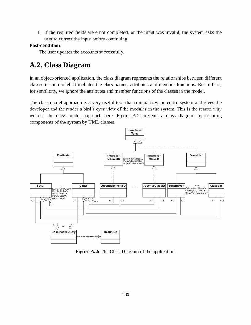
139
1. If the required fields were not completed, or the input was invalid, the system asks the
user to correct the input before continuing.
Post-condition.
The user updates the accounts successfully.
A.2. Class Diagram
In an object-oriented application, the class diagram represents the relationships between different
classes in the model. It includes the class names, attributes and member functions. But in here,
for simplicity, we ignore the attributes and member functions of the classes in the model.
The class model approach is a very useful tool that summarizes the entire system and gives the
developer and the reader a bird’s eyes view of the modules in the system. This is the reason why
we use the class model approach here. Figure A.2 presents a class diagram representing
components of the system by UML classes.
Figure A.2: The Class Diagram of the application.
140
Appendix B: The main classes and methods in the
implementation of the application
This section presents the implementation of the system architecture as described in chapter 5
through the classes and methods, is comprised of the Client Side (Section B.1) and the Server
Side logic (Section B.2).
B.1. Client Side
The Client Side implementation, which adopts the MVP design pattern, is described in this
section.
Model
The Model of our application consists of the following major Java interfaces and classes:
Identifier: an interface that is used as a new reference data type of identifiers.
ClassID, DescriptionID, ObjectID, PropertyID, ResourceID, SchemaID: The interfaces
that inherit the interface Identifier. They are used to describe specific types of identifiers.
JocondeClassID, JocondeDescriptionID, JocondePropertyID, JocondeResourceID,
JocondeSchemaID, LouvreObjectID, and so on: The classes that implement the above
interfaces of specific types of identifiers. They contain the information in detail of identifiers
that depend on a specific organization.
Variable: an interface that is used as a new reference data type of free variables.
ClassVar, DescriptionVar, ObjectVar, PropertyVar, ResourceVar, SchemaVar: The
classes that implement the interface Variable. They contain the information in detail of
specific free variables.
Predicate: a class contains all the information of the general predicate.
SchCl, SchPr, Dom, Ran, IsaCl, IsaPr, DescCl, DescPr, DescOf, PartOf, ClInst and
PrInst: The classes contain the information in detail of specific predicates. Note that, if all
fields of a specific predicate are identifiers then it is a fact. Otherwise, if at least one field of
a specific predicate is a variable then it is an atomic query.
ConjunctiveQuery: a class which contains all the information of the conjunctive query.
Each conjunctive query includes an array of atomic queries.
ResultSet: a class which contains all the data of the result set of query execution.
Presenter
141
Below, we quote a brief description for each Presenter we have implemented in our application.
LoginPresenter: The presenter of LoginView. Responsible for the validation of the user’s
input so as to login him into the system.
PredicatesListPresenter: The presenter of PredicatesListView. It handles the operation of
choosing the relation name of a predicate.
SchClPresenter, SchPrPresenter, DescClPresenter, DescOfPresenter, DescPrPresenter,
DomPresenter, RanPresenter, IsaClPresenter, IsaPrPresenter, PartOfPresenter: The
presenters that are associated with their views, respectively. They handle the operations of
viewing, adding and editing specific predicates.
PredicatesPresenter: The presenter of PredicatesView. It handles the operation of viewing
the list of predicates and deleting a set of selected predicates.
QueriesListPresenter: The presenter of QueriesListView. It handles the operation of
choosing the relation name of an atomic query.
SchClQueryPresenter, SchPrQueryPresenter, DescClQueryPresenter,
DescOfQueryPresenter, DescPrQueryPresenter, DomQueryPresenter,
RanQueryPresenter, IsaClQueryPresenter, IsaPrQueryPresenter,
PartOfQueryPresenter, ClInstQueryPresenter, PrInstQueryPresenter: The presenters
that are associated with their views, respectively. They handle the operations of creating,
reviewing and executing a specific atomic query.
QueryResultsPresenter: The presenter of QueriesResultsView. It handles the operation of
viewing the results of query execution in two different formats of identifiers.
View
Below, we quote a brief description for each View we have implemented in our application, in
that each View is a Java class.
LoginView: The first view of the application where the users try to login to the system.
PredicatesListView: Allows content providers to choose the relation name of a predicate.
SchClView, SchPrView, DescClView, DescOfView, DescPrView, DomView, RanView,
IsaClView, IsaPrView, PartOfView: Allows content providers to view, add and edit a specific
predicate.
PredicatesView: Allows content providers to view the list of predicates and delete a set of
selected predicates.
QueriesListView: Allows end users to choose the relation name of an atomic query.
SchClQueryView, SchPrQueryView, DescClQueryView, DescOfQueryView,
DescPrQueryView, DomQueryView, RanQueryView, IsaClQueryView,
IsaPrQueryView, PartOfQueryView, ClInstQueryView, PrInstQueryView: Allows end
users to create, review and execute a specific atomic query.
142
QueryResultsView: Allows end users to view the results of query execution in two different
formats of identifiers.
AppController
Below, we quote a brief description for each AppController we have implemented in our
application, in that each AppController is a Java class.
PredicatesController: A controller that is used to handle view transitions of predicates via
browser history changes
QueriesController: A controller that is used to handle view transitions of queries via
browser history changes
B.2. Server Side
In this section we provide the set of services that comprise the middleware concealing the
application’s business logic from the client. The implemented main methods are listed below,
providing brief descriptions regarding each method’s functionality.
insert_tuple: A method that is used to insert one tuple into the RDF store
delete_tuple: A method that is used to delete one tuple from the RDF store
load_tuples: A method that is used to retrieve all triples in the RDF store
isexistentfact: A method that is used to check whether a tuple existed in the metadata base or
not
TupletoTriple: A method that is used to map from tuples to triples
TripletoTuple: A method that is used to map from triples to tuples
getFreeVariables: A method that extracts from a conjunctive query the set of the free
variables
getGraphPatternOfAtomicQuery: A method that is used to obtain the graph pattern of any
atomic query which is either an independent query or a component part of the conjunctive
query
getGraphPattern: A method that is used to map a conjunctive query into an equivalent
graph pattern
select_dl: A method that is used for retrieval of data from the triple store
update_dl: A method that is used for update or deletion of the data in the triple store
143
References
[1] L. Candela, G. Athanasopoulos, D. Castelli, K. El Raheb, P. Innocenti, Y. Ioannidis, A.
Katifori, A. Nika, G. Vullo, and S. Ross (DELOS Reference Model Authors: L.
Candela, D. Castelli, N. Ferro, Y. Ioannidis, G. Koutrika, C. Meghini, P. Pagano, S.
Ross, D. Soergel, M. Agosti, M. Dobreva, V. Katifori, and H. Schuldt). The Digital
Library Reference Model. DL.org: Coordination Action on Digital Library
Interoperability, Best Practices and Modelling Foundations, April 2011.
[2] L. Candela, D. Castelli, N. Ferro, Y. Ioannidis, G. Koutrika, C. Meghini, P. Pagano, S.
Ross, D. Soergel, M. Agosti, M. Dobreva, V. Katifori, H. Schuldt. The DELOS Digital
Library Reference Model - Foundations for Digital Libraries. DELOS Network of
Excellence on Digital Libraries, 2007.
[3] L. Candela, D. Castelli, Y. Ioannidis, G. Koutrika, P. Pagano, S. Ross, H.-J. Schek, H.
Schuldt, and C. Thanos. Setting the Foundations of Digital Libraries: The DELOS
Manifesto. D-Lib Magazine, Vol. 13 No. 3/4, March/April 2007.
[4] IQura Technologies. Digital Library Solution.
http://www.iqura.com/pdf/IQura%20Digital%20Library%20Solution%201.1.pdf
[5] Edward A. Fox, Robert M. Akscyn, Richard K. Furuta, and John J. Leggett. Digital
libraries. Communications of the ACM, Volume 38 Issue 4, pp.22–28, April 1995.
[6] Christine L. Borgman. What are digital libraries? Competing visions. Information
Processing and Management: an International Journal - Special issue on progress
toward digital libraries, Volume 35 Issue 3, pp.227–243, May 1999.
[7] Ali Shiri. Digital library research: Current developments and trends. Library Review,
Vol. 52 Iss: 5, pp.198 – 202, 2003.
[8] Ian Witten and David Bainbridge. How to build a digital library, 2003.
[9] Sun Microsystems. Digital Library Technology Trends, August 2002.
http://www.ncsi.iisc.ernet.in/raja/is214/is214-2005-01-04/digital_library_trends-
020923.pdf
[10] Suleman, Hussein. Design and architecture of digital libraries, in Chowdhury, G G and
S Foo, Eds. Digital Libraries and Information Access: Research Perspectives, chapter 2,
pages 13-28. Facet Publishing, 2002
[11] Harnad, S., Brody, T., Vallières, F., Carr, L., Hitchcock, S., Gingras, Y., Oppenheim,C.,
Stamerjohans, H., and Hilf, E. R. (2004) The Access/Impact Problem and the Green and
Gold Roads to Open Access , Serial Review, Elsevier, 30 (4), 310-314.
[12] Lagoze, C., Van de Sompel, H., Nelson, M., and Warner, S., (2002a) The Open
Archives Initiative Protocol for Metadata Harvesting, Version 2.0, Open Archives
Initiative. http://www.openarchives.org/OAI/2.0/openarchivesprotocol.htm
144
[13] Allinson, J., Carr, L., Downing, J., Flanders, D. F., Francois, S., Jones, R., Lewis, S.,
Morrey, M., Robson, G., and Taylor, N. (2010) SWORD AtomPub Profile version 1.3:
Simple Webservice Offering Repository Deposit.
http://www.swordapp.org/docs/sword-profile-1.3.html
[14] Payette, S., and Lagoze, C. (1998) Flexible and Extensible Digital Object and
Repository Architecture (FEDORA), in Nicholaou, C., and Stephanidis, C. (eds):
Research and Advanced Technology for Digital Libraries, Springer, LNCS 1513.
[15] Webley, L., Chipeperekwa, T., and Suleman, H. (2011) Creating a National Electronic
Thesis and Dissertation Portal in South Africa, in Olivier, E., and Suleman, H. (eds):
Proceedings of 14th
International Symposium on Electronic Theses and Dissertations
(ETD 2011), Cape Town, 13-15 September.
http://dl.cs.uct.ac.za/conferences/etd2011/papers/etd2011_webley.pdf
[16] Suleman, H. (2007) Digital Libraries Without Databases: The Bleek and Lloyd
Collection, in Kovacs, L., Fuhr, N., and Meghini, C. (eds): Proceedings of Research and
Advanced Technology for Digital Libraries, 11th European Conference (ECDL 2007),
16-19 September, Budapest, Hungary, 392-403.
[17] Mikhail, Y., Adly, N., and Nagi, M. (2011) DAR: Institutional Repository Integration in
Action, in Gradmann, S., Borri, F., Meghini, C., and Schuldt, H. (eds): Proceedings of
Research and Advanced Technology for Digital Libraries, International Conference on
Theory and Practice of Digital Libraries (TPDL 2007), 26-28 September, Budapest,
Hungary, Springer, LNCS 6966, 348-359.
[18] Witten, I. H., Bainbridge, D., and Boddie, S. (2001) Power to the people: end-user
building of digital library collections, in Fox, E. A., and Borgman, C. L. (eds):
Proceedings of the 1st ACM/IEEE-CS Joint Conference on Digital Libraries, ACM, 94-
103.
[19] Rakesh Agrawal, Anastasia Ailamaki, Philip A. Bernstein, Eric A. Brewer, Michael J.
Carey, Surajit Chaudhuri, AnHai Doan, Daniela Florescu, Michael J. Franklin, Hector
Garcia Molina, Johannes Gehrke, Le Gruenwald, Laura M. Haas, Alon Y. Halevy,
Joseph M. Hellerstein, Yannis E. Ioannidis, Hank F. Korth, Donald Kossmann, Samuel
Madden, Roger Magoulas, Beng Chin Ooi, Tim OReilly, Raghu Ramakrishnan, Sunita
Sarawagi, Michael Stonebraker, Alexander S. Szalay, and GerhardWeikum. The
Claremont report on database research. SIGMOD Record (ACM) 37 (3):9-19, 2008.
[20] Hewett, Baecker, Card, Carey, Gasen, Mantei, Perlman, Strong, and Verplank. ACM
SIGCHI Curricula for Human - Computer Interaction, July 2009.
http://old.sigchi.org/cdg/cdg2.html#2_1.
[21] Soumen Chakrabarti, Martin Ester, Usama Fayyad, Johannes Gehrke, Jiawei Han,
Shinichi Morishita, Gregory Piatetsky-Shapiro, and Wei Wang (Intensive Working
Group of ACM SIGKDD Curriculum Committee). Data Mining Curriculum: A
Proposal (Version 1.0). ACM SIGKDD, April 2006.
145
http://www.sigkdd.org/curriculum.php.
[22] Usama Fayyad, Gregory Piatetsky-Shapiro, and Padhraic Smyth. From Data Mining to
Knowledge Discovery in Databases. AI Magazine, Volume 17, pp.37–54, 1996.
[23] T. Tamer Özsu and Patrick Valduriez. Principles of Distributed Databases. Springer,
3nd edition, 2011.
[24] Christopher D. Manning, Prabhakar Raghavan, and Hinrich Schütze. Introduction to
Information Retrieval. Cambridge University Press, 1 edition, July 7, 2008.
http://nlp.stanford.edu/IR-book/.
[25] Enrico Motta, John Domingue, Simon Buckingham Shum, ―ScholOnto: an ontology-
based digital library server for research documents and discourse,‖ vol. 3, no. 1, 2000.
[26] Vittore Casarosa, ―DELOS Reference Model for Digital Libraries,‖ in Elag 2007
Conference, vol. 1, Barcelona, 2007.
[27] Laura C. Savastinuk, Michael E. Casey, ―Service for the next-generation library,‖ vol.
33, no. 14, 2006.
[28] Jane Secker, ―Social Software, Libraries and distance learners: literature review,‖
London, 2008.
[29] Hu Xiaojing, Fan Bingsi, ―Library 2.0: Building the New Library Services,‖ 2006.
[30] Jack M. Maness, ―Library 2.0 Theory: Web 2.0 and Its Implications for Libraries,‖ vol.
8, no. 2, 2006.
[31] Gonçalves, M.A., Fox, E.A., Watson, L.T. and Kipp, N.A. 2004. Streams, structures,
spaces, scenarios, societies (5s). ACM Transactions on Information Systems. 22, 2 (Apr.
2004), 270-312.
[32] Carlo Meghini, Nicolas Spyratos, Tsuyoshi Sugibuchi, and Jitao Yang. A Model for
Digital Libraries and its Translation to RDF. Submitted for publication.
[33] Carlo Meghini, Nicolas Spyratos, and Jitao Yang. A data model for digital libraries.
International Journal on Digital Libraries, Volume 11 Number 1, pp.41-56, March 2010.
[34] Jitao Yang, A Data Model for Digital Libraries, Ph.D. Thesis, Université Paris-Sud,
May 2012. Thesis Advisors: Prof. Nicolas Spyratos, Dr. Carlo Meghini.
[35] Ian Jacobs and Norman Walsh. Architecture of the World Wide Web, Volume One.
W3C Recommendation, WWW Consortium, December 2004.
http://www.w3.org/TR/webarch/.
[36] Graham Klyne and Jeremy J. Carroll. Resource description framework (RDF): Concepts
and abstract syntax. W3C Recommendation, WWW Consortium, February 2004.
http://www.w3.org/TR/rdf-concepts/.
[37] Eric Prud’hommeaux and Andy Seaborne. SPARQL Query Language for RDF. W3C
Recommendation, January 2008. http://www.w3.org/TR/rdf-sparql-query/.
[38] Patrick J. Hayes and Harry Halpin. In Defense of Ambiguity. International Journal on
Semantic Web and Information Systems (IJSWIS), Volume 4 Issue 2, pp.1–18, 2008.
146
[39] V. Presutti and A. Gangemi. Identity of Resources and Entities on the Web.
International Journal on Semantic Web and Information Systems, 4(2): 49–72, 2008.
[40] Harry Halpin and Presutti Valentina. An Ontology of Resources for Linked Data.
Proceedings of the Linked Data on the Web (LDOW 2009), WWW2009 Workshop,
Madrid, Spain, April 20-24, 2009.
http://events.linkeddata.org/ldow2009/papers/ldow2009_paper19.pdf.
[41] RFC 3986 - Uniform Resource Identifier (URI): Generic Syntax.
http://tools.ietf.org/html/rfc3986/.
[42] Frank Manola and Eric Miller. RDF Primer. W3C Recommendation, WWW
Consortium, February 2004. http://www.w3.org/TR/rdf-primer/.
[43] Carlo Meghini, Martin Doerr, and Nicolas Spyratos. Managing co-reference knowledge
for data integration. Proceedings of the 2009 conference on Information Modelling and
Knowledge Bases XX, Yasushi Kiyoki, Takahiro Tokuda, Hannu Jaakkola, Xing Chen,
and Naofumi Yoshida (Eds.). IOS Press, Amsterdam, The Netherlands, pp.224–244,
January 2009.
[44] Raymond Reiter. Towards a Logical Reconstruction of Relational Database Theory. On
Conceptual Modelling (Intervale), Michael L. Brodie, John Mylopoulos, and Joachim
W. Schmidt (Editors), Springer Verlag, New York, pp.191–233, 1982.
[45] Franz Baader, Diego Calvanese, Deborah L. McGuinness, Daniele Nardi, and Peter F.
Patel-Schneider, editors. The Description Logic Handbook: Theory, Implementation,
and Applications. Cambridge University Press, 2nd edition, 2003.
[46] Dublin Core Metadata Initiative. Dublin Core Metadata Element Set, Version 1.1, June
2012. http://dublincore.org/documents/dces/.
[47] Martin Doerr. The CIDOC conceptual reference model: An ontological approach to
semantic interoperability of metadata. AI Magazine, 24(3):75–92, 2003.
[48] John Wylie Lloyd. Foundations of Logic Programming. Springer Verlag, 1987.
[49] Giuseppe Castagna. Covariance and contravariance: conflict without a cause. ACM
Transactions on Programming Languages and Systems (TOPLAS), Volume 17 Issue 3,
pp.431–447, May 1995.
[50] Stephen Cole Kleene. Mathematical Logic, 1967. Dover Publications, Reprinted 2002.
[51] Jiewen Huang, Daniel J. Abadi, and Kun Ren. Scalable sparql querying of large rdf
graphs. PVLDB, 4(11):1123–1134, 2011.
[52] Datalog Package. http://www.ccs.neu.edu/home/ramsdell/tools/datalog/index.html.
[53] Datalog Educational System (DES).
http://www.fdi.ucm.es/profesor/fernan/DES/index.html.
[54] IRIS - Integrated Rule Inference System. http://iris-reasoner.org/.
[55] Sergio Munoz-Venegas, Jorge Perez, and Claudio Gutierrez. Simple and efficient
minimal RDFS. Journal of Web Semantics, 7:220–234, 2009.
147
[56] Dan Brickley and R.V. Guha. RDF vocabulary description language 1.0: RDF schema.
W3C Recommendation, WWW Consortium, February 2004.
http://www.w3.org/TR/rdf-schema/.
[57] Patrick Hayes. RDF Semantics. W3C Recommendation,WWWConsortium, February
2004. http://www.w3.org/TR/rdf-mt/.
[58] Carl Lagoze and Herbert Van de Sompel (Editors (OAI Executive)). Open Archives
Initiative Object Reuse and Exchange: ORE User Guide - Primer, October 17, 2008.
http://www.openarchives.org/ore/1.0/primer.
[59] Herman J. ter Horst. Completeness, decidability and complexity of entailment for RDF
schema and a semantic extension involving the OWL vocabulary. Journal of Web
Semantics, 3:79–115, 2005.
[60] Steve Harris and Andy Seaborne. SPARQL 1.1 Query Language. W3C Working Draft,
May 12, 2011. http://www.w3.org/TR/sparql11-query/.
[61] Jorge Perez, Marcelo Arenas, and Claudio Gutierrez. Semantics and complexity of
SPARQL. ACM Transactions on Database Systems (TODS), 34(3), August 2009.
[62] Ajax: A New Approach to Web Applications. Garrett, Jesse James. 2005.
[63] Fielding, Roy T., et al. RFC 2616: Hypertext Transfer Protocol -- HTTP/1.1. June 1999.
http://tools.ietf.org/html/rfc2616.
[64] Dave Raggett, Arnaud Le Hors, Ian Jacobs. HTML 4.01. W3C Recommendation, 24
December 1999. http://www.w3.org/TR/html4/.
[65] Resource Description Framework (RDF) Model and Syntax Specification.
http://www.w3.org/TR/PR-rdf-syntax/.
[66] Kendall Grant Clark, Lee Feigenbaum, and Elias Torres. SPARQL Protocol for RDF,
2008. Published online on January 15th, 2008 at http://www.w3.org/TR/2008/REC-rdf-
sparql-protocol-20080115/.
[67] Simon Schenk, Paul Gearon, and Alexandre Passant. SPARQL 1.1 Update. Technical
report, W3C, 2008. Published online on October 14th, 2010 at
http://www.w3.org/TR/2010/WD-sparql11-update-20101014/.
[68] 27. Potel, Mike. MVP: Model-View-Presenter. The Taligent Programming Model for
C++ and Java. 1996. https://developers.google.com/web-toolkit/articles/mvp-
architecture
[69] Reenskaug, Trygve. MVC XEROX PARC 1978-79.
[70] Rigaux, P., Spyratos, N.: Metadata inference for document retrieval in a distributed
repository. In: Maher, M.J. (ed.) ASIAN 2004. LNCS, vol. 3321, pp. 418–436
[71] Tsuyoshi Sugibuchi, Ly Anh Tuan, Nicolas Spyratos: ―Metadata Inference for
Description Authoring in a Document Composition Environment‖ IRCDL 2012 - 8th
Italian Research Conference on Digital Libraries, Bari, Italy, February 9-10, 2012.
148
[72] Everett J.O., Bobrow D.G., Stolle R., Crouch R., Paiva V. de, Condoravdi C., Berg M.
van den, Polanyi L. (2002): Making ontologies work for resolving redundancies across
documents. Communications of the ACM (45) 2: 55-60.
[73] Stuckenschmidt, H., Harmelen F. van (2004): Generating and managing metadata for
web-based information. Knowledge based systems, (17) 5/6: 201-206.
[74] Wei C.P., Hu P.J., Dong Y.X. (2002): Managing document categories in e-commerce
environments: an evolution-based approach. European journal of information systems,
(11) 208-222.
[75] F. Bapst, R. Bruegger, A. Zramdini, R.Ingold. Integrated Multi-Agent Architecture for
Assisted Document Recognition. In Document Analysis Systems II, Series in Machine
Perception and Atricial Intelligence, vol 29, World Scientific, 1998, pp. 301-317.
[76] Peter Fankhauser and Yi Xu, MarkItUp! - An incremental approach to document
structure recognition, Electronic Publishing, 1993, pages 447-456.
[77] A. Belaïd, Y. Chenevoy. Constraint Propagation vs Syntactical Analysis for the Logical
Structure Recognition of Library References. N. A. Murshed and F. Bortolozzi (Eds.),
Lecture Notes in Computer Science 1339, BSDIA'97, Springer, pp. 153-164, Curitiba,
Brazil, November 2--5, 1997.
[78] S. Bonhomme, C. Roisin. Interactively Restructuring HTML Documents. Computer
Network and ISDN Systems, vol. 28, num. 7-11, pp. 1075-1084, May 1996.
[79] E. Akpotsui, V. Quint, C. Roisin. Type Modelling for Document Transformation in
Structured Editing Systems. Mathematical and Computer Modelling, vol. 25, num. 4,
pp. 1-19, 1997.
[80] S. Bonhomme, C. Roisin. Transformations de documents électroniques. Document
Numérique, vol. 1, num. 3, 1997.
[81] S. Bonhomme. Transformations de documents structurés : une combinaison des
approches déclaratives et automatiques, Doctorat d'informatique, Université Joseph
Fourier, décembre 1998.
[82] ―XSL Transformations,‖ World Wide Web Consortium (W3C),
http://www.w3.org/TR/xslt , November 1999.
[83] S. Abiteboul, R. Goldman, J. McHugh, V. Vassalos, Y. Zhuge. ―Views for
Semistructured Data‖, Tech. Report, Dept of Computer Science, Stanford University,
1999.
[84] W3C, W3C note, Schema for Object-Oriented XML 2.0. 30 Jul 1999.
http://www.w3.org/TR/NOTE-SOX/
[85] Watters, C., Shepherd, M.: Research issues for virtual documents. In: Workshop on
Virtual Documents, Hypertext Functionality and the Web at the 8th International World
Wide Web Conference, Toronto (1999)
[86] Ranwez, S., Crampes, M.: Conceptual documents and hypertext documents are two
different forms of virtual document. In: Workshop on Virtual Documents, Hypertext
149
Functionality and the Web at the 8th InternationalWorldWideWebConference. Toronto,
May (1999)
[87] WikiWeb—Web Based Corporation Tools. http://www.wikiweb.com (2011). Accessed
12 May 2011
[88] Caumanns, J.: A Modular framework for the creation of dynamic documents.
In:Workshop on Virtual Documents, Hypertext Functionality and the Web at the 8th
International World Wide Web Conference, Toronto (1999)
[89] Iksal, S., Garlatti, S.: Revisiting and versioning in virtual special reports. In:
eThirdWorkshop on Adaptive Hypertext and Hypermedia, 12th ACM Conference on
Hypertext and Hypermedia, Arhus (2001)
[90] Tetchueng, J.L., Garlatti, S., Laube, S.: A context-aware learning system based on
generic scenarios and the theory in didactic anthropology of knowledge. Int. J. Comput.
Sci.Appl. 5(1), 71–87 (2008)
[91] Qu, Y., Hu, W., Cheng, G.: Constructing virtual documents for ontology matching. In:
Proceedings of the 15th International Conference on World Wide Web, Edinburgh, pp.
23–31 (2006)
[92] Zhang, Li, Bieber, Michael, Song, Min, Oria, Vincent and Millard, David E. (2010)
Supplementing virtual documents with just-in-time hypermedia functionality.
International Journal on Digital Libraries, 11, (3), 155-168. (doi:10.1007/s00799-011-
0065-9).