Embed Size (px)
Citation preview
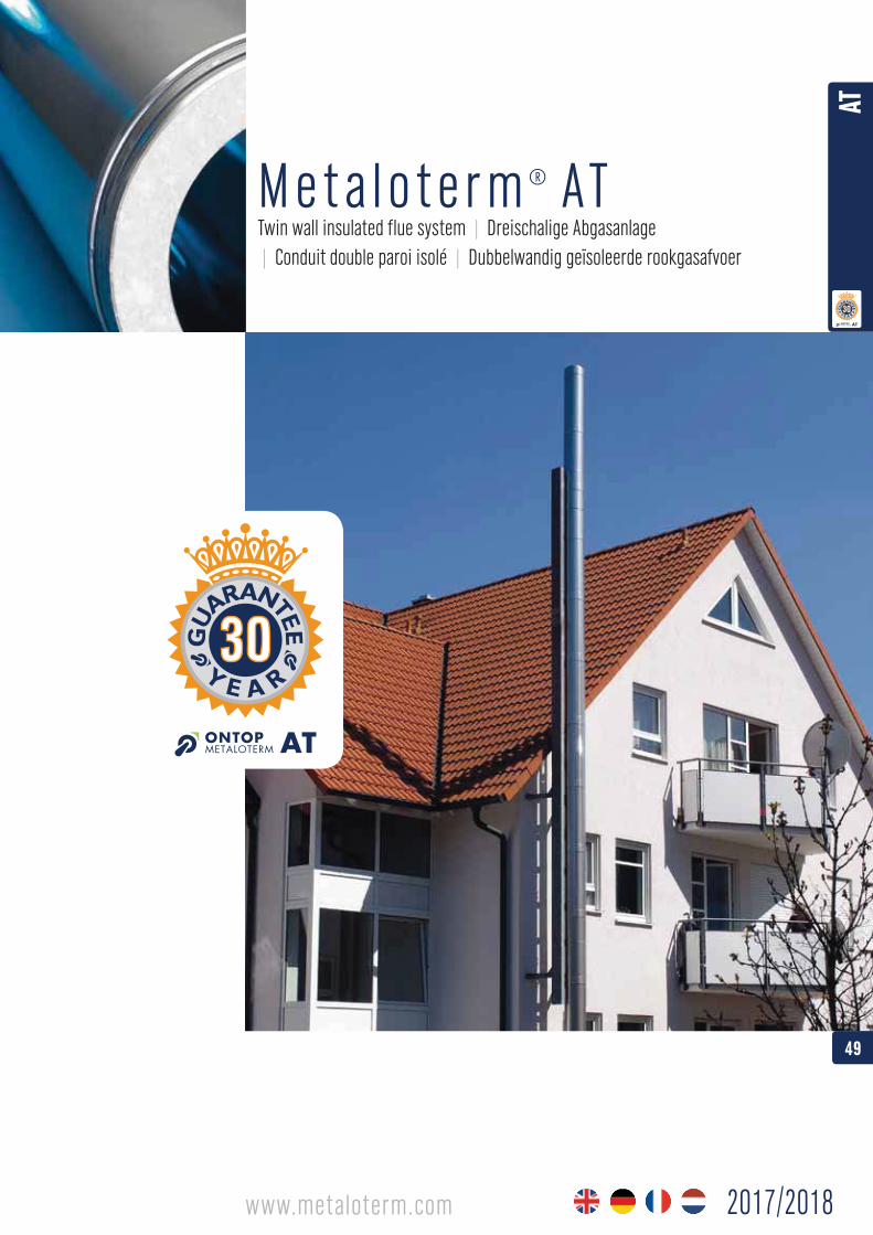
M e t a l o t e r m ®
Twin wall insulated flue system | Dreischalige Abgasanlage | Conduit double paroi isolé | Dubbelwandig geïsoleerde rookgasafvoer
A T
49
AT
2017/2018www.metaloterm.com
ATD100 ....................................
ATDA ........................................
ATDO ........................................
ATDOC ......................................
-
AT 100/50/40/30/20 ............... p. 62
ATA ..........................................
ATA 00 .....................................
ATABK ...................................... p. 63
ATAC ........................................ p. 60
ATAC 00 ................................... p. 60
ATAL......................................... p. 60
ATAPO ...................................... p. 63
...................................... p. 63
.................................. p. 75
ATAS ........................................ p. 60
ATB 15 ..................................... p. 61
ATB 30 ..................................... p. 61
ATB 45 ..................................... p. 61
ATCP ........................................ p. 75
ATDH........................................ p. 71
ATDP ........................................ p. 71
ATDQ ........................................ p. 64
ATE .......................................... p. 75
ATEM ....................................... p. 62
ATIB30/50/70 .......................... p. 67
ATIBAPH................................... p. 71
ATIBAPL ................................... p. 71
ATIBBH .................................... p. 66
ATIBBL ..................................... p. 67
ATIBBP1 ................................... p. 66
ATIBBP2 ................................... p. 67
ATIBBP3 ................................... p. 67
ATIBDQ .................................... p. 68
ATIBLE .....................................
ATIBLS .....................................
ATIBMD .................................... p. 68
ATIBMH .................................... p. 68
ATIBMR ....................................
ATIBMT..................................... p. 68
ATIBP10 ...................................
ATIBP30 ...................................
ATIBPN .....................................
ATIBR ....................................... p. 70
ATIBR2 ..................................... p. 70
ATIBS ....................................... p. 70
ATIBVH ..................................... p. 70
ATIBVL ..................................... p. 70
ATIBVQ ..................................... p. 68
ATIBVQL ................................... p. 68
ATIBVR ..................................... p. 70
ATK .......................................... p. 73
ATKG ........................................ p. 73
ATKK ........................................ p. 74
ATKR ........................................ p. 73
ATKSI ....................................... p. 74
ATKV ........................................ p. 73
ATLE ......................................... p. 71
ATLS ........................................ p. 71
ATM ......................................... p. 73
ATMA ....................................... p. 73
ATMB ....................................... p. 64
ATMB2 ..................................... p. 64
ATMB3 ..................................... p. 64
ATMBAH1 ................................. p. 65
ATMBAH2 ................................. p. 65
ATMBAH3 ................................. p. 65
ATMBV2/3/4............................. p. 65
ATMF ........................................ p. 74
ATMO ....................................... p. 65
ATN .......................................... p. 62
ATOH 2/4 ................................. p. 64
ATOL 1/2 .................................. p. 65
ATPH ........................................ p. 66
ATPP ........................................ p. 62
ATRBK ...................................... p. 61
ATS .......................................... p. 72
ATSA ........................................ p. 60
ATSI100/50.............................. p. 63
ATSK ........................................ p. 66
ATT 45 ..................................... p. 61
..................................... p. 61
ATTE ......................................... p. 74
ATTOPZ .................................... p. 72
ATTR ........................................ p. 62
ATVQ ........................................ p. 66
ATVR ........................................ p. 60
ATTWF ...................................... p. 75
| Schnellsuche | Recherche rapide |
AT

TABLE OF CONTENT INHALT INDEX INHOUD
System description - Systembeschreibung - Description système - Systeembeschrijving -Technical details Technische Daten Caractéristiques techniques Technische eigenschappen 53
Installation guidelines Einbaurichtlinien Directives d’installation Installatie richtlijnen 54
Adaptors/ Anschlußstücke/ Raccords/ Aansluitstukken/ 61Increasers/Reducers Übergangsstücke Augmentations/Réductions Verlopen
Elbows Bögen Coudes Bochten 61
Tee-pieces T-Stücke Tés T-stukken 61
Lengths and other chimney Längen und andere Longueurs et autres Secties en anderecomponents Abgaselemente éléments schoorsteenelementen 62
Silencers Schalldämpfer Silencieux Dempers 63
Base plates/ Fundamentverankerung/ Plaque de départ/ Voetplaat/ 63Supports/ Zwischenstützen/ Eléments de fixation/ Ondersteuningen/Wall brackets/ Gebäudeabspannbänder/ Brides murales/ Muurbeugels/Locking bands Klemmbänder Brides de sécurité Klembanden
Iso-block Iso-block Iso-block Iso-block 66
Flashings/ Dachdurchführungen/ Solins de toit/ Dakplaten/Storm collars Regenabweiser Collets de solin Stormkragen 71
Others Anderen Autres Overigen 74
Applications Aufbaubeispiele Applications Opbouwvoorbeelden 76
51
AT
2017/2018
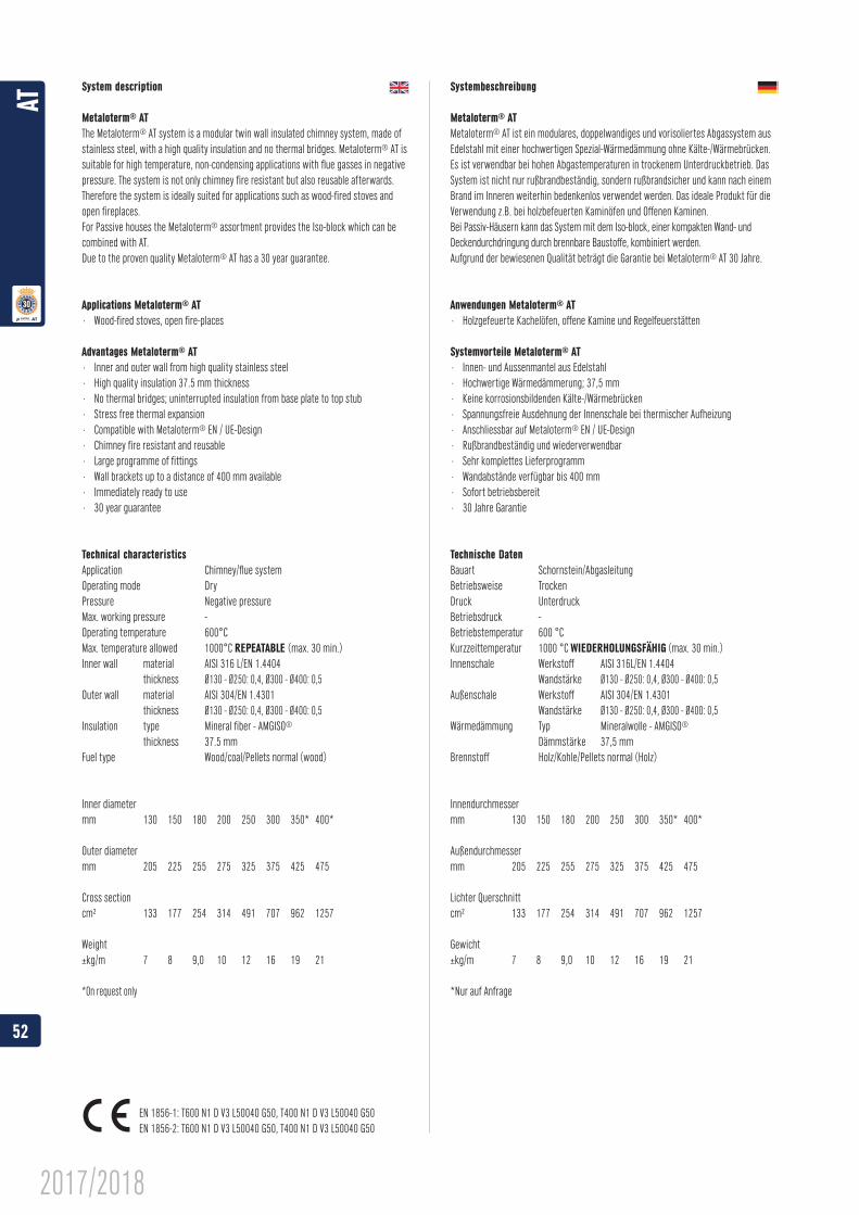
System description
Metaloterm® ATThe Metaloterm® AT system is a modular twin wall insulated chimney system, made of stainless steel, with a high quality insulation and no thermal bridges. Metaloterm® AT is suitable for high temperature, non-condensing applications with flue gasses in negative pressure. The system is not only chimney fire resistant but also reusable afterwards. Therefore the system is ideally suited for applications such as wood-fired stoves and open fireplaces.For Passive houses the Metaloterm® assortment provides the Iso-block which can be combined with AT.Due to the proven quality Metaloterm® AT has a 30 year guarantee.
Applications Metaloterm® AT· Wood-fired stoves, open fire-places
Advantages Metaloterm® AT· Inner and outer wall from high quality stainless steel· High quality insulation 37.5 mm thickness· No thermal bridges; uninterrupted insulation from base plate to top stub· Stress free thermal expansion· Compatible with Metaloterm®
· Chimney fire resistant and reusable· Large programme of fittings· Wall brackets up to a distance of 400 mm available· Immediately ready to use· 30 year guarantee
Technical characteristicsApplication Chimney/flue systemOperating mode DryPressure Negative pressureMax. working pressure -Operating temperature 600°CMax. temperature allowed 1000°C (max. 30 min.)Inner wall material AISI 316 L/EN 1.4404 thickness Ø130 - Ø250: 0,4, Ø300 - Ø400: 0,5Outer wall material AISI 304/EN 1.4301 thickness Ø130 - Ø250: 0,4, Ø300 - Ø400: 0,5Insulation type Mineral fiber - AMGISO®
thickness 37.5 mmFuel type Wood/coal/Pellets normal (wood)
Inner diametermm 130 150 180 200 250 300 350* 400*
Outer diametermm 205 225 255 275 325 375 425 475
Cross section
Weight
*On request only
Systembeschreibung
Metaloterm® ATMetaloterm® AT ist ein modulares, doppelwandiges und vorisoliertes Abgassystem aus Edelstahl mit einer hochwertigen Spezial-Wärmedämmung ohne Kälte-/Wärmebrücken.
System ist nicht nur rußbrandbeständig, sondern rußbrandsicher und kann nach einem Brand im Inneren weiterhin bedenkenlos verwendet werden. Das ideale Produkt für die Verwendung z.B. bei holzbefeuerten Kaminöfen und Offenen Kaminen.Bei Passiv-Häusern kann das System mit dem Iso-block, einer kompakten Wand- und Deckendurchdringung durch brennbare Baustoffe, kombiniert werden. Aufgrund der bewiesenen Qualität beträgt die Garantie bei Metaloterm® AT 30 Jahre.
Anwendungen Metaloterm® AT· Holzgefeuerte Kachelöfen, offene Kamine und Regelfeuerstätten
Systemvorteile Metaloterm® AT· Innen- und Aussenmantel aus Edelstahl· Hochwertige Wärmedämmerung; 37,5 mm· Keine korrosionsbildenden Kälte-/Wärmebrücken· Spannungsfreie Ausdehnung der Innenschale bei thermischer Aufheizung· Anschliessbar auf Metaloterm®
· Rußbrandbeständig und wiederverwendbar· Sehr komplettes Lieferprogramm· Wandabstände verfügbar bis 400 mm· Sofort betriebsbereit· 30 Jahre Garantie
Technische DatenBauart Schornstein/AbgasleitungBetriebsweise Trocken
Betriebsdruck -Betriebstemperatur 600 °CKurzzeittemperatur 1000 °C WIEDERHOLUNGSFÄHIG (max. 30 min.)Innenschale Werkstoff AISI 316L/EN 1.4404 Wandstärke Ø130 - Ø250: 0,4, Ø300 - Ø400: 0,5Außenschale Werkstoff AISI 304/EN 1.4301 Wandstärke Ø130 - Ø250: 0,4, Ø300 - Ø400: 0,5Wärmedämmung Typ Mineralwolle - AMGISO®
Dämmstärke 37,5 mmBrennstoff Holz/Kohle/Pellets normal (Holz)
Innendurchmessermm 130 150 180 200 250 300 350* 400*
Außendurchmessermm 205 225 255 275 325 375 425 475
Lichter Querschnitt
Gewicht
*Nur auf Anfrage
EN 1856-1: T600 N1 D V3 L50040 G50, T400 N1 D V3 L50040 G50EN 1856-2: T600 N1 D V3 L50040 G50, T400 N1 D V3 L50040 G50
52
AT
2017/2018
Description système
Metaloterm® ATLe système Metaloterm® AT est un conduit de fumées modulaire à double paroi isolé, en acier inoxydable, avec une isolation de haute qualité sans pont thermique. Metaloterm® AT est particulièrement adapté pour de hautes températures, pour des applications sans condensation, en pression négative. Ce système ne résiste pas seulement aux feux de cheminée, il est également réutilisable après un feu de cheminée. Il est donc parfait pour les applications telles que les poêles à bois, inserts, ainsi que les foyers ouverts.Pour les maisons passives, Metaloterm® peut fournir une sortie de toiture isolée et
Du fait de ses grandes qualités, le système Metaloterm® AT est garanti 30 ans
Applications de Metaloterm® AT· Foyers ouverts, foyers fermés et poêles à bois
Avantages de Metaloterm® AT· Parois intérieure et extériere en acier inoxidable de haute qualité· Isolant breveté d’une grande efficacité, 37,5 mm· Pas de ponts thermiques car l’isolation est continue sur tout le parcours de fumées· Structure permettant une libre dilatation de la paroi intérieure· Raccorder à Metaloterm®
· Résistant au feu de cheminée et réutilisable
· Brides murales réglables jusqu’à 400 mm· Peut etre utilisé directement apres la pose· Garantie de 30 ans
Domaine d’application Cheminée/conduit de fuméeNature des fumées SèchePression DépressionPression maximale -Température en continu 600°CTempérature accidentelle 1000°C (max. 30 min.)Paroi intérieure matériau AISI 316L/EN 1.4404 épaisseur Ø130 - Ø250: 0,4, Ø300 - Ø400: 0,5Paroi extérieure matériau AISI 304/EN 1.4301 épaisseur Ø130 - Ø250: 0,4, Ø300 - Ø400: 0,5Isolant type Fibre minérale - AMGISO®
épaisseur 37,5 mmCombustibles Bois/charbon/pellets normal (bois)
Diamètre intérieurmm 130 150 180 200 250 300 350* 400*
Diamètre extérieurmm 205 225 255 275 325 375 425 475
Section
Poids
Metaloterm® ATHet Metaloterm® AT systeem is een modulair dubbelwandig schoorsteen systeem van roestvaststaal met een hoogwaardige isolatie en zonder warmtebruggen. Metaloterm® AT is geschikt voor toepassingen in onderdruk, met hoge rookgastemperaturen waarbij geen condensatie optreedt. Het systeem is niet alleen schoorsteenbrandbestendig, het is ook herbruikbaar nadien.Het systeem is daardoor bij uitstek geschikt voor toepassing op bijvoorbeeld houtkachels en openhaarden. Voor passief huizen is het Iso-block opgenomen in het Metaloterm® assortiment, dat perfect kan worden gecombineerd met AT.Dankzij de bewezen kwaliteit geniet het Metaloterm® AT een garantie van maar liefst 30 jaar.
Toepassingen van Metaloterm® AT· Open haarden en open en gesloten houtkachels
Voordelen van Metaloterm® AT· Binnen en buitenmantel van hoogwaardig roestvaststaal· Hoogwaardige isolatie 37,5 mm dik· Geen warmtebruggen door ononderbroken isolatielaag· Thermische uitzetting mogelijk; trekvaste sluiting· Aansluitbaar op Metaloterm®
· Schoorsteenbrandbestendig en herbruikbaar· Zeer uitgebreid assortiment hulpstukken· Beugels tot wandafstand van 400 mm beschikbaar· Direct gebruiksklaar· 30 jaar garantie
Technische eigenschappenToepassing Schoorsteen/rookgasafvoerAggregatie Niet condenserendDruk OnderdrukMaximale overdruk -Bedrijfstemperatuur 600 °CMaximaal toegestane temperatuur 1000 °C HERHAALBAAR (max. 30 min.)Binnenmantel materiaal AISI 316L/EN 1.4404 wanddikte Ø130 - Ø250: 0,4, Ø300 - Ø400: 0,5Buitenmantel materiaal AISI 304/EN 1.4301 wanddikte Ø130 - Ø250: 0,4, Ø300 - Ø400: 0,5Isolatie type minerale wol - AMGISO®
dikte 37,5 mmBrandstof Hout/kolen/pellets normal (hout)
Binnendiametermm 130 150 180 200 250 300 350* 400*
Buitendiametermm 205 225 255 275 325 375 425 475
Doorlaat
Gewicht
*Enkel op aanvraag
EN 1856-1: T600 N1 D V3 L50040 G50, T400 N1 D V3 L50040 G50EN 1856-2: T600 N1 D V3 L50040 G50, T400 N1 D V3 L50040 G50 NL: AT+ omkokering EN 1856-1: T600 N1 D V3 L50040 G0
53
AT
2017/2018
AC
CD
BB
BInstallation guidelines | Einbaurichtlinien | Directives d’installation |
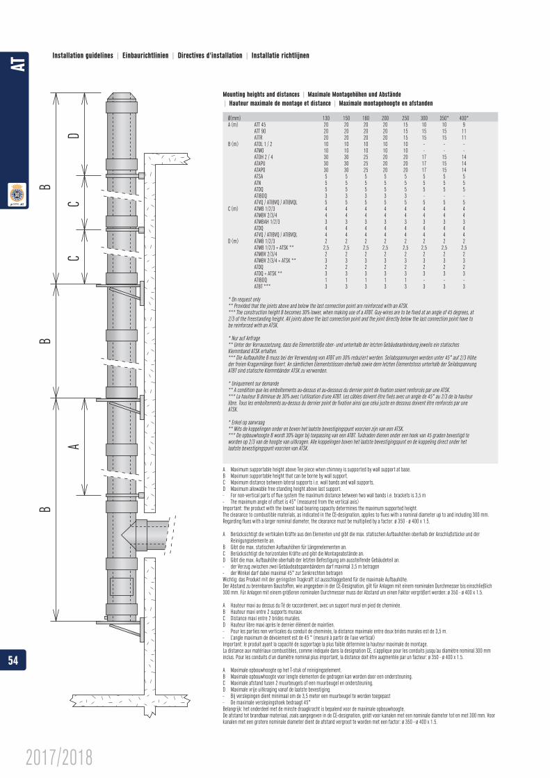
A Maximum supportable height above Tee piece when chimney is supported by wall support at base.B Maximum supportable height that can be borne by wall support.C Maximum distance between lateral supports i.e. wall bands and wall supports.D Maximum allowable free standing height above last support.- For non-vertical parts of flue system the maximum distance between two wall bands i.e. brackets is 3,5 m- The maximum angle of offset is 45° (measured from the vertical axis) Important: the product with the lowest load bearing capacity determines the maximum supported height.The clearance to combustible materials, as indicated in the CE-designation, applies to flues with a nominal diameter up to and including 300 mm. Regarding flues with a larger nominal diameter, the clearance must be multiplied by a factor: ø 350 - ø 400 x 1.5.
A Berücksichtigt die vertikalen Kräfte aus den Elementen und gibt die max. statischen Aufbauhöhen oberhalb der Anschlußstücke und der Reinigungselemente an.
B Gibt die max. statischen Aufbauhöhen für Längenelementen an.C Berücksichtigt die horizontalen Kräfte und gibt die Montageabstände an.D Gibt die max. Aufbauhöhe oberhalb der letzten Befestigung am aussteifende Gebäudeteil an.- der Verzug zwischen zwei Gebäudeabspannbändern darf maximal 3,5 m betragen - der Winkel darf dabei maximal 45° zur Senkrechten betragen Wichtig: das Produkt mit der geringsten Tragkraft ist ausschlaggebend für die maximale Aufbauhöhe.Der Abstand zu brennbaren Baustoffen, wie angegeben in der CE-Designation, gilt für Anlagen mit einem nominalen Durchmesser bis einschließlich 300 mm. Für Anlagen mit einem größeren nominalen Durchmesser muss der Abstand um einen Faktor vergrößert werden: ø 350 - ø 400 x 1.5.
A Hauteur maxi au dessus du Té de raccordement, avec un support mural en pied de cheminée.B Hauteur maxi entre 2 supports muraux.C Distance maxi entre 2 brides murales.D Hauteur libre maxi après le dernier élément de maintien.- Pour les parties non verticales du conduit de cheminée, la distance maximale entre deux brides murales est de 3,5 m.- L’angle maximum de dévoiement est de 45 ° (mesuré à partir de l’axe vertical) Important: le produit ayant la capacité de supportage la plus faible détermine la hauteur maximale de montage.La distance aux matériaux combustibles, comme indiquée dans la designation CE, s’applique pour les conduits jusqu’au diamètre nominal 300 mm inclus. Pour les conduits d’un diamètre nominal plus important, la distance doit être augmentée par un facteur: ø 350 - ø 400 x 1.5.
A Maximale opbouwhoogte op het T-stuk of reinigingselement.B Maximale opbouwhoogte voor lengte elementen die gedragen kan worden door een ondersteuning.C Maximale afstand tusen 2 muurbeugels of een muurbeugel en ondersteuning.D Maximale vrije uitkraging vanaf de laatste bevestiging.- Bij verslepingen dient minimaal om de 3,5 meter een muurbeugel te worden toegepast- De maximale verslepingshoek bedraagt 45° Belangrijk: het onderdeel met de minste draagkracht is bepalend voor de maximale opbouwhoogte.De afstand tot brandbaar materiaal, zoals aangegeven in de CE-designation, geldt voor kanalen met een nominale diameter tot en met 300 mm. Voor kanalen met een grotere nominale diameter dient de afstand vergroot te worden met een factor: ø 350 - ø 400 x 1.5.
Mounting heights and distances | | |
Ø(mm) 130 150 180 200 250 300 350* 400*
ATTR 20 20 20 20 15 15 15 11B (m) ATOL 1 / 2 10 10 10 10 10 - - - ATMO 10 10 10 10 10 - - - ATOH 2 / 4 30 30 25 20 20 17 15 14
ATAPO 30 30 25 20 20 17 15 14 ATSA 5 5 5 5 5 5 5 5 ATN 5 5 5 5 5 5 5 5 ATDQ 5 5 5 5 5 5 5 5 ATIBDQ 3 3 3 3 3 - - - ATVQ / ATIBVQ / ATIBVQL 5 5 5 5 5 5 5 5C (m) ATMB 1/2/3 4 4 4 4 4 4 4 4 ATMBV 2/3/4 4 4 4 4 4 4 4 4 ATMBAH 1/2/3 3 3 3 3 3 3 3 3 ATDQ 4 4 4 4 4 4 4 4 ATVQ / ATIBVQ / ATIBVQL 4 4 4 4 4 4 4 4D (m) ATMB 1/2/3 2 2 2 2 2 2 2 2 ATMB 1/2/3 + ATSK ** 2,5 2,5 2,5 2,5 2,5 2,5 2,5 2,5 ATMBV 2/3/4 2 2 2 2 2 2 2 2 ATMBV 2/3/4 + ATSK ** 3 3 3 3 3 3 3 3 ATDQ 2 2 2 2 2 2 2 2 ATDQ + ATSK ** 3 3 3 3 3 3 3 3 ATIBDQ 1 1 1 1 1 - - - ATBT *** 3 3 3 3 3 3 3 3
* On request only** Provided that the joints above and below the last connection point are reinforced with an ATSK.
2/3 of the freestanding height. All joints above the last connection point and the joint directly below the last connection point have to be reinforced with an ATSK.
* Nur auf Anfrage
Klemmband ATSK erhalten.
der freien Kragarmlänge fixiert. An sämtlichen Elementstössen oberhalb sowie dem letzten Elementstoss unterhalb der Seilabspannung ATBT sind statische Klemmbänder ATSK zu verwenden.
** A condition que les emboîtements au-dessus et au-dessous du dernier point de fixation soient renforcés par une ATSK.
libre. Tous les emboîtements au-dessus du dernier point de fixation ainsi que celui juste en dessous doivent être renforcés par une ATSK.
* Enkel op aanvraag** Mits de koppelingen onder en boven het laatste bevestigingspunt voorzien zijn van een ATSK.
worden op 2/3 van de hoogte van uitkragen. Alle koppelingen boven het laatste bevestigingspunt en de koppeling direct onder het laatste bevestigingspunt voorzien van ATSK.
54
AT
2017/2018
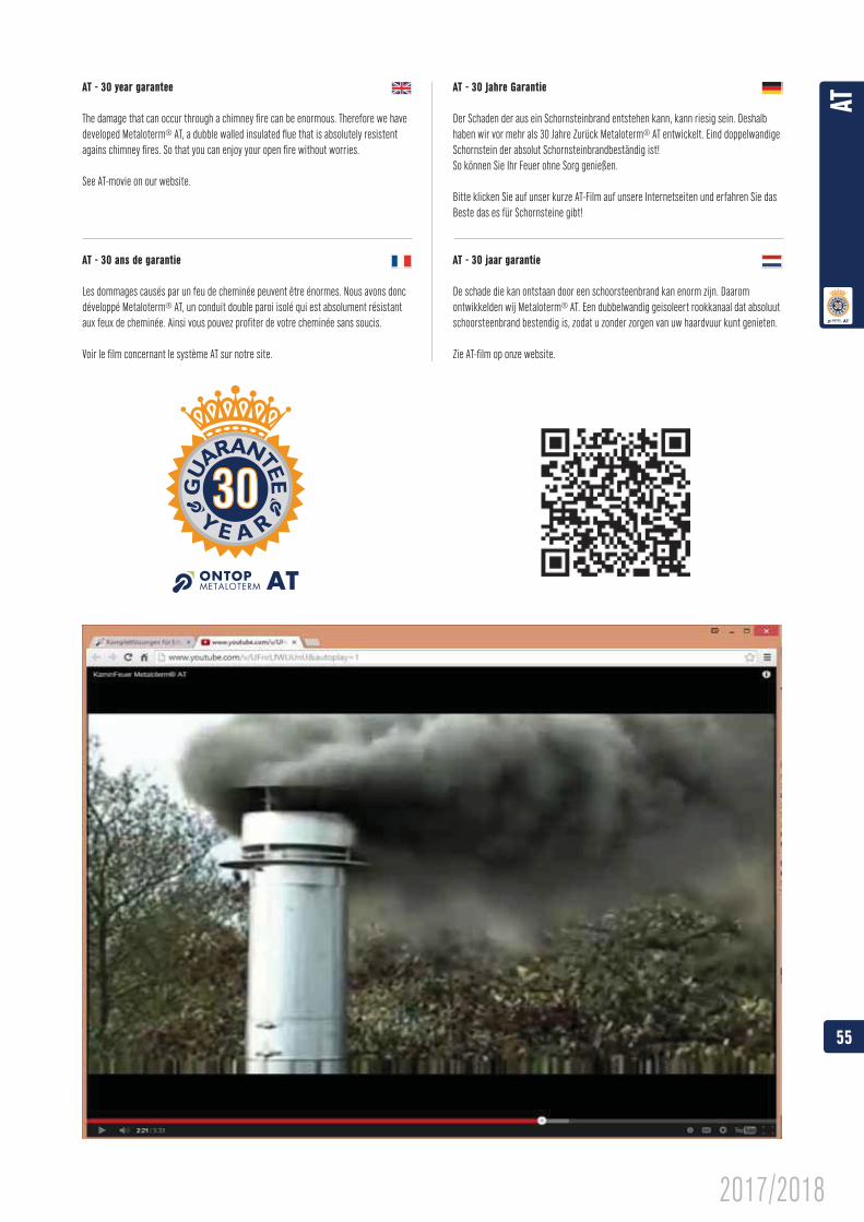
The damage that can occur through a chimney fire can be enormous. Therefore we have developed Metaloterm® AT, a dubble walled insulated flue that is absolutely resistent agains chimney fires. So that you can enjoy your open fire without worries.
See AT-movie on our website.
Der Schaden der aus ein Schornsteinbrand entstehen kann, kann riesig sein. Deshalb haben wir vor mehr als 30 Jahre Zurück Metaloterm® AT entwickelt. Eind doppelwandige Schornstein der absolut Schornsteinbrandbeständig ist! So können Sie Ihr Feuer ohne Sorg genießen.
Bitte klicken Sie auf unser kurze AT-Film auf unsere Internetseiten und erfahren Sie das Beste das es für Schornsteine gibt!
De schade die kan ontstaan door een schoorsteenbrand kan enorm zijn. Daarom ontwikkelden wij Metaloterm® AT. Een dubbelwandig geisoleert rookkanaal dat absoluut schoorsteenbrand bestendig is, zodat u zonder zorgen van uw haardvuur kunt genieten.
Zie AT-film op onze website.
Les dommages causés par un feu de cheminée peuvent être énormes. Nous avons donc développé Metaloterm® AT, un conduit double paroi isolé qui est absolument résistant aux feux de cheminée. Ainsi vous pouvez profiter de votre cheminée sans soucis.
Voir le film concernant le système AT sur notre site.
55
AT
2017/2018
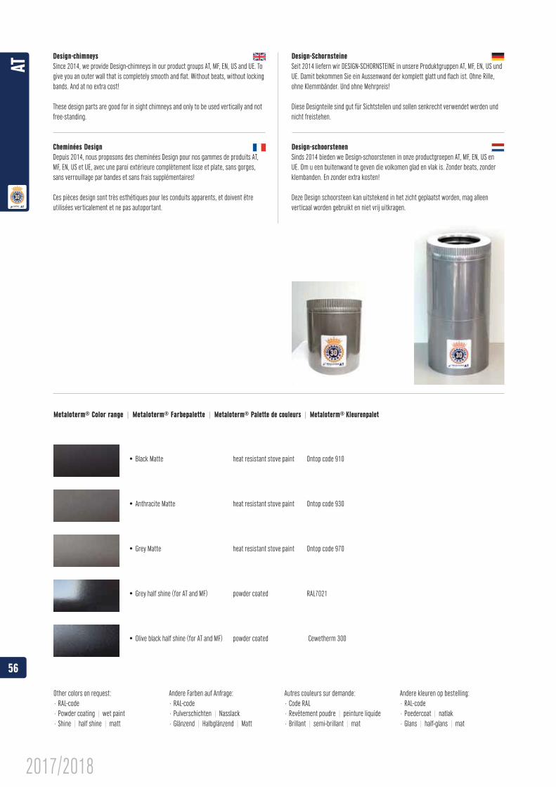
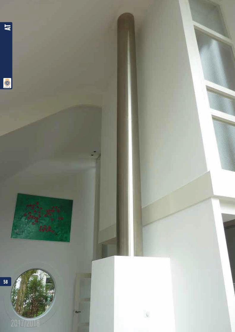
give you an outer wall that is completely smooth and flat. Without beats, without locking bands. And at no extra cost!
These design parts are good for in sight chimneys and only to be used vertically and not free-standing.
Depuis 2014, nous proposons des cheminées Design pour nos gammes de produits AT,
sans verrouillage par bandes et sans frais supplémentaires!
Ces pièces design sont très esthétiques pour les conduits apparents, et doivent être utilisées verticalement et ne pas autoportant.
Diese Designteile sind gut für Sichtstellen und sollen senkrecht verwendet werden und nicht freistehen.
klembanden. En zonder extra kosten!
Deze Design schoorsteen kan uitstekend in het zicht geplaatst worden, mag alleen verticaal worden gebruikt en niet vrij uitkragen.
Metaloterm® Color range | Metaloterm® Farbepalette | Metaloterm® | Metaloterm®
Other colors on request:· RAL-code· Powder coating | wet paint· Shine | half shine | matt
Andere Farben auf Anfrage:· RAL-code· Pulverschichten | Nasslack· Glänzend | Halbglänzend | Matt
Autres couleurs sur demande:· Code RAL· Revêtement poudre | peinture liquide· Brillant | semi-brillant | mat
Andere kleuren op bestelling:· RAL-code· Poedercoat | natlak· Glans | half-glans | mat
56
AT
2017/2018
M e t a l o t e r m® U SMounting instructions / Montageanweisung / Mode de montage / Istruzioni di montaggio / Montagehandleiding
Fig. 1 Top/Oben/Supérieure/Alto/Boven
Fig. 2
Fig. 3
EN
Regulation
Specific instructions
Installation
CE
DE
Baurecht
Gerätespezifische Vorschriften
Montage
CE
1. Unique identification code of the product-type:Twin walled stainless steel system with insulation - Metaloterm® AD according to EN 1856-1:2009
2. Type, batch or serial number or any other element allowing identification of the construction product as required under Article 11(4):
Model 1 DN (ø130–300) EN 1856-1 T600 H1 D V2 L50050 O50 Model 1 DN (ø350–450) EN 1856-1 T600 H1 D V2 L50060 O75 Model 1 DN (ø500–600) EN 1856-1 T600 H1 D V2 L50060 O100 Model 1 DN ( > ø600) EN 1856-1 T600 H1 D V2 L50060 O200
Model 2 DN (ø130–300) EN 1856-1 T600 N1 D V2 L50040 G50 Model 2 DN (ø350–450) EN 1856-1 T600 N1 D V2 L50060 G75 Model 2 DN (ø500–600) EN 1856-1 T600 N1 D V2 L50060 G100 Model 2 DN ( > ø600) EN 1856-1 T600 N1 D V2 L50060 G200
3. Intended use or uses of the construction product, in accordance with the applicable harmonised technical specification, as foreseen by the manufacturer:Convey the products of combustion from heating appliances to the outside atmosphere
4. Name, registered trade name or registered trade mark and contact address of the manufacturer as required under Article 11(5):Ontop B.V.
Postbus 135, 4330 AC MiddelburgOude Veerseweg 23, 4332 SH Middelburg
The NetherlandsT: +31 (0)118 68 99 00F: +31 (0)118 68 99 99E: [email protected]
5. Where applicable, name and contact address of the authorised representative whose mandate covers the tasks specified in Article 12(2):Not applicable
6. System or systems of assessment and verification of constancy of performance of the construction product as set out in CPR, Annex V:System 2+ and System 4
Marsbruchstraße 186D-44287 Dortmund
(Kenn-Nr. 0432)
7. Notified factory production control certification body No. 0432 performed the initial inspection of the manufacturing plant and of factory production control and the continuous surveillance, assessment and evaluation of factory production control and issued the certificate of conformity 0432-CPR-21999130 of the factory production control.
AD_DoP_21999130_EN1856-1_EN_ENo. 21999130ENDeclaration of Performance Metaloterm® AD
WE CARE
1/3
The Building Blocks are created in AutoCad 2012.
® Building Blocks Manual
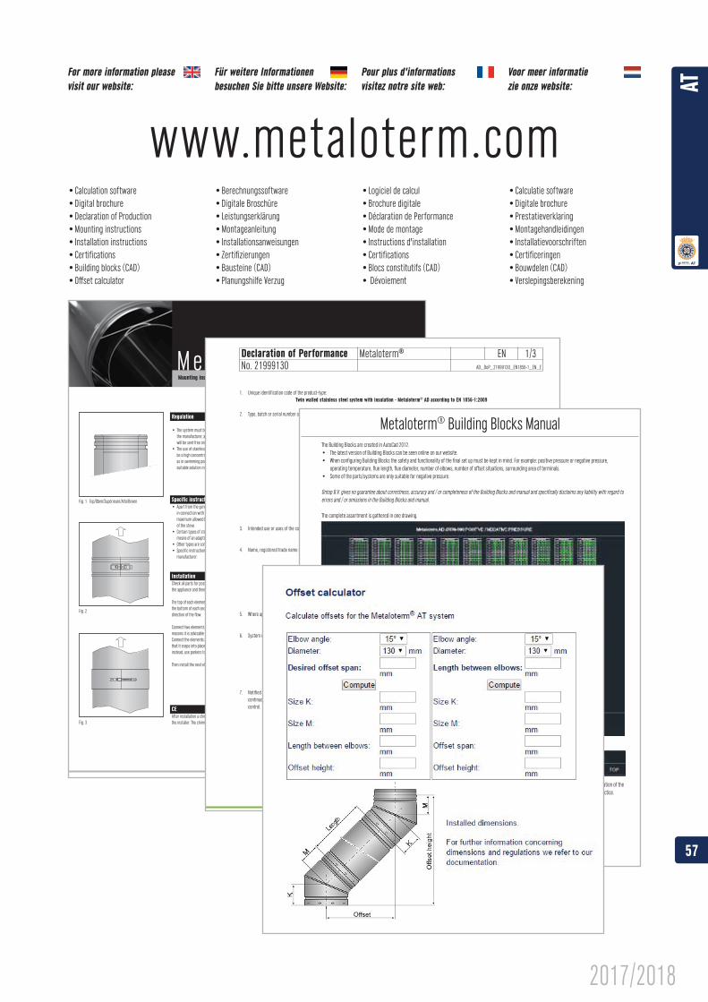
For more information please visit our website: besuchen Sie bitte unsere Website: visitez notre site web:
Voor meer informatie zie onze website:
www.metaloterm.com
57
AT
2017/2018
58
AT
2017/2018
280
D1
D
50
965
Ø
50
D
D1
280
960
Ø
Ø
960
00 cm Design
Ø
A
7226
7
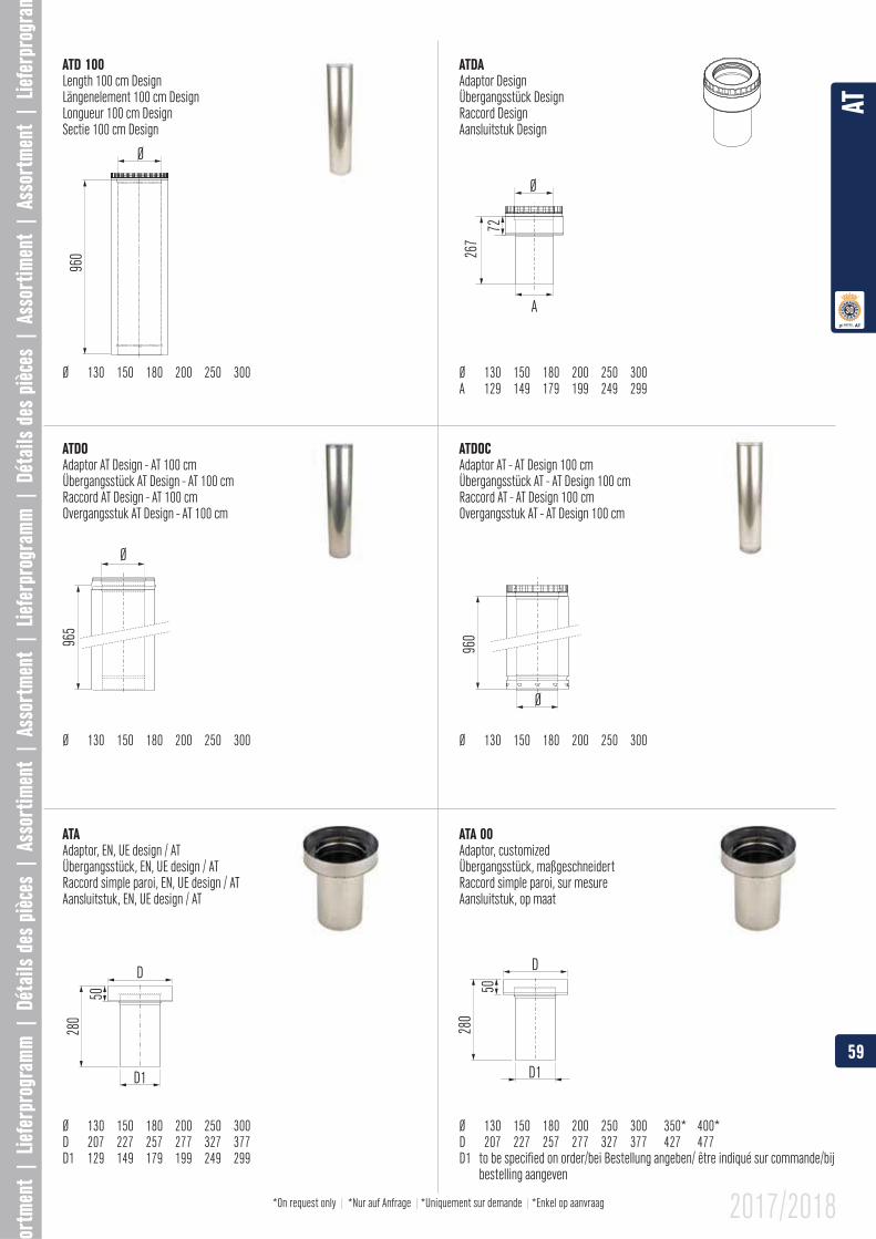
ATA
Ø 130 150 180 200 250 300D 207 227 257 277 327 377
ATA 00Adaptor, customizedÜbergangsstück, maßgeschneidertRaccord simple paroi, sur mesureAansluitstuk, op maat
Ø 130 150 180 200 250 300 350* 400*D 207 227 257 277 327 377 427 477D1 to be specified on order/bei Bestellung angeben/ être indiqué sur commande/bij
bestelling aangeven
ATD 100Length 100 cm DesignLängenelement 100 cm DesignLongueur 100 cm DesignSectie 100 cm Design
Ø 130 150 180 200 250 300
ATDAAdaptor DesignÜbergangsstück DesignRaccord DesignAansluitstuk Design
Ø 130 150 180 200 250 300
ATDOAdaptor AT Design - AT 100 cmÜbergangsstück AT Design - AT 100 cmRaccord AT Design - AT 100 cmOvergangsstuk AT Design - AT 100 cm
Ø 130 150 180 200 250 300
ATDOCAdaptor AT - AT Design 100 cmÜbergangsstück AT - AT Design 100 cmRaccord AT - AT Design 100 cmOvergangsstuk AT - AT Design 100 cm
Ø 130 150 180 200 250 300
*On request only | *Nur auf Anfrage | |*Enkel op aanvraag
59
AT
2017/2018
DD1
Ø
65100
5010
5
H
D
Ø
65100
180H
Ø6510
0
D
Ø
D
H55
D1D2
Ø
965
280
D
ØA
65
315
1515
Ø 10 200
200
240
10
25x25x1
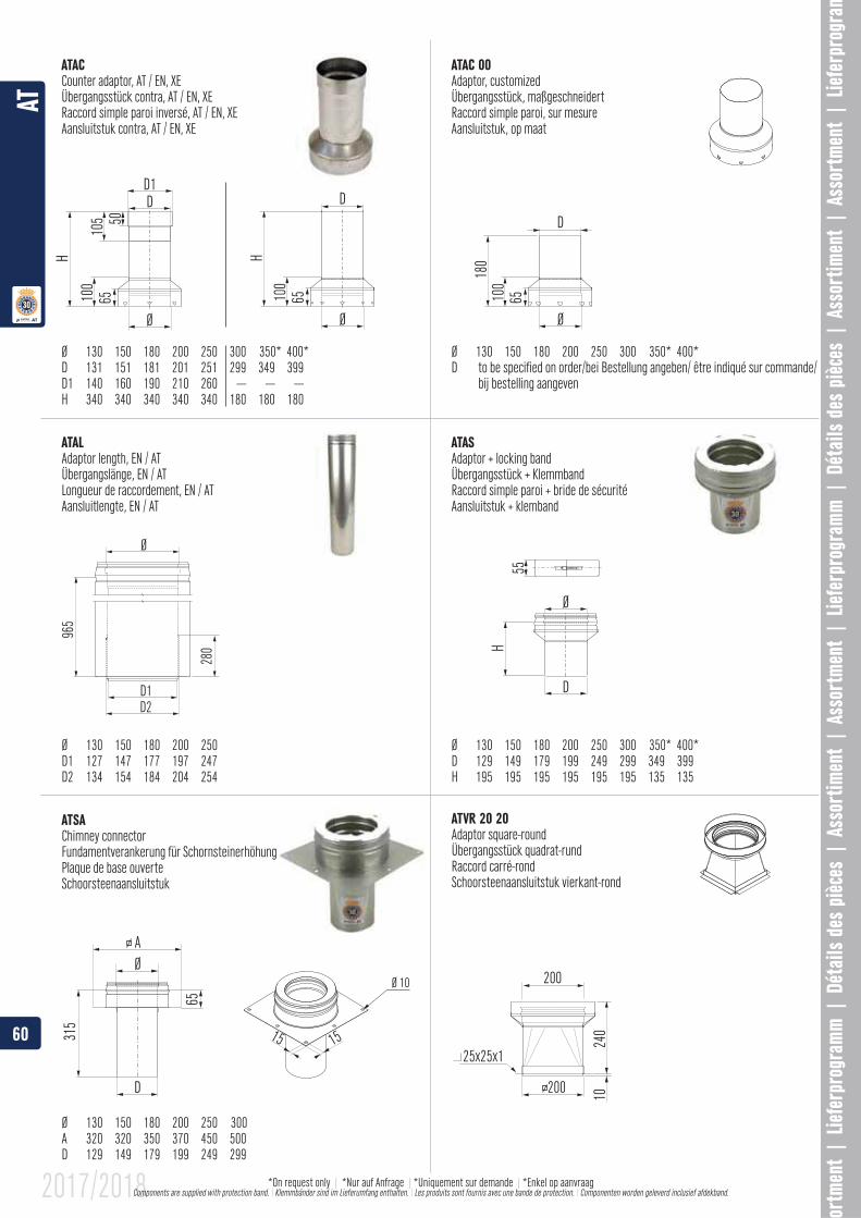
ATAC
Ø 130 150 180 200 250 300 350* 400*
H 340 340 340 340 340 180 180 180
ATAC 00Adaptor, customizedÜbergangsstück, maßgeschneidertRaccord simple paroi, sur mesureAansluitstuk, op maat
Ø 130 150 180 200 250 300 350* 400*D to be specified on order/bei Bestellung angeben/ être indiqué sur commande/
bij bestelling aangeven
ATASAdaptor + locking bandÜbergangsstück + KlemmbandRaccord simple paroi + bride de sécuritéAansluitstuk + klemband
Ø 130 150 180 200 250 300 350* 400*
ATALAdaptor length, EN / ATÜbergangslänge, EN / ATLongueur de raccordement, EN / ATAansluitlengte, EN / AT
Ø 130 150 180 200 250
D2 134 154 184 204 254
ATSAChimney connectorFundamentverankerung für SchornsteinerhöhungPlaque de base ouverteSchoorsteenaansluitstuk
Ø 130 150 180 200 250 300A 320 320 350 370 450 500
ATVR 20 20Adaptor square-roundÜbergangsstück quadrat-rundRaccord carré-rondSchoorsteenaansluitstuk vierkant-rond
60
AT
2017/2018 *On request only | *Nur auf Anfrage | |*Enkel op aanvraag Components are supplied with protection band. \ Klemmbänder sind im Lieferumfang enthalten. \ Les produits sont fournis avec une bande de protection. \ Componenten worden geleverd inclusief afdekband.
k
Ø
45º
mx
y
H
Ø
y
H1
y2
x
45°
45
15º
k
Ø
m
x
y
30º
k
Ø
m
x
y
60
H
Ø
y
x
90°
k 90
1"
Ø
H55
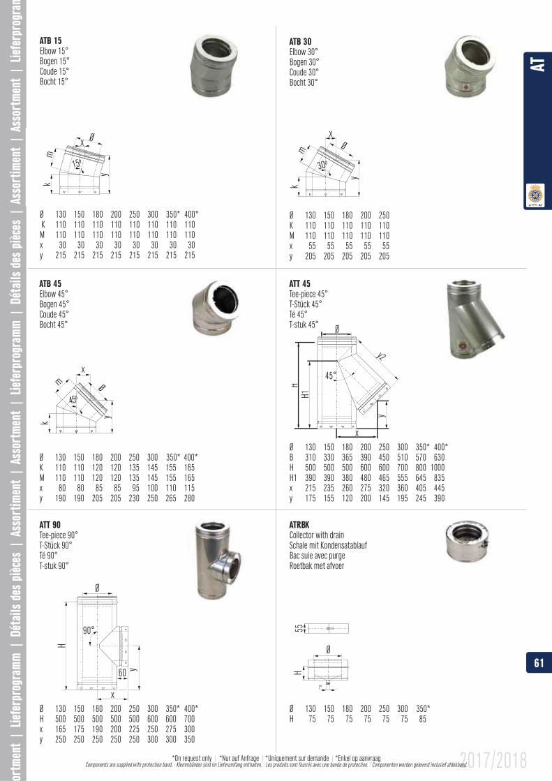
ATB 15Elbow 15°Bogen 15°Coude 15°Bocht 15°
Ø 130 150 180 200 250 300 350* 400* K 110 110 110 110 110 110 110 110M 110 110 110 110 110 110 110 110x 30 30 30 30 30 30 30 30y 215 215 215 215 215 215 215 215
ATB 45Elbow 45°Bogen 45°Coude 45°Bocht 45°
Ø 130 150 180 200 250 300 350* 400*K 110 110 120 120 135 145 155 165M 110 110 120 120 135 145 155 165
ATT 45Tee-piece 45°T-Stück 45°Té 45°T-stuk 45°
Ø 130 150 180 200 250 300 350* 400*
H 500 500 500 600 600 700 800 1000
x 215 235 260 275 320 360 405 445
ATB 30Elbow 30°Bogen 30°Coude 30°Bocht 30°
Ø 130 150 180 200 250K 110 110 110 110 110M 110 110 110 110 110x 55 55 55 55 55y 205 205 205 205 205
Collector with drainSchale mit KondensatablaufBac suie avec purgeRoetbak met afvoer
Ø 130 150 180 200 250 300 350* H 75 75 75 75 75 75 85
ATT 90
Ø 130 150 180 200 250 300 350* 400*H 500 500 500 500 500 600 600 700
y 250 250 250 250 250 300 300 350
61
AT
2017/2018*On request only | *Nur auf Anfrage | |*Enkel op aanvraag Components are supplied with protection band. \ Klemmbänder sind im Lieferumfang enthalten. \ Les produits sont fournis avec une bande de protection. \ Componenten worden geleverd inclusief afdekband.
Ø
L max
L min
H
H1-H
2-H3
-H4-
H5
Ø
Ø
150
Min.1
50 M
ax.30
0
D1D2
180
R
Ø 6,5
Ø
290
500 18
0120
Ø
85
1”
200
ATE
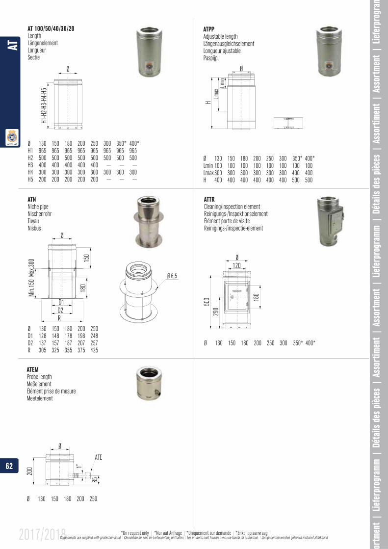
Adjustable lengthLängenausgleichselementLongueur ajustablePaspijp
Ø 130 150 180 200 250 300 350* 400*Lmin 100 100 100 100 100 100 100 100Lmax 300 300 300 300 300 300 400 400H 400 400 400 400 400 400 500 500
AT 100/50/40/30/20LengthLängenelementLongueurSectie
Ø 130 150 180 200 250 300 350* 400*
H2 500 500 500 500 500 500 500 500H3 400 400 400 400 400 --- --- ---H4 300 300 300 300 300 300 300 300H5 200 200 200 200 200 --- --- ---
ATNNiche pipeNischenrohrTuyauNisbus
Ø 130 150 180 200 250
D2 137 157 187 207 257R 305 325 355 375 425
ATTRCleaning/inspection elementReinigungs-/InspektionselementÉlément porte de visiteReinigings-/inspectie-element
Ø 130 150 180 200 250 300 350* 400*
ATEMProbe lengthMeßelementÉlément prise de mesureMeetelement
Ø 130 150 180 200 250
62
AT
2017/2018 *On request only | *Nur auf Anfrage | |*Enkel op aanvraag Components are supplied with protection band. \ Klemmbänder sind im Lieferumfang enthalten. \ Les produits sont fournis avec une bande de protection. \ Componenten worden geleverd inclusief afdekband.
Ø
H1 - H
2
D
5412
560
A
Ø
Ø 11
B
18
A
105
Ø
1”
1818
Ø 11
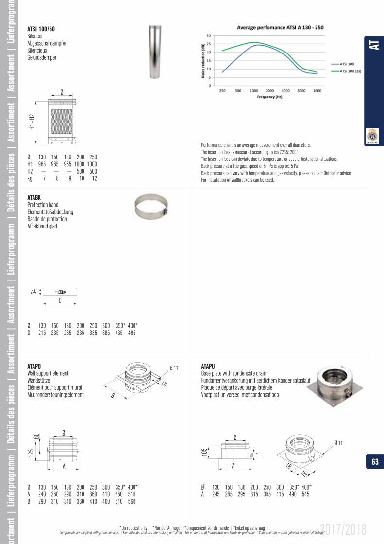
ATSI 100/50SilencerAbgasschalldämpferSilencieuxGeluidsdemper
Ø 130 150 180 200 250
H2 --- --- --- 500 500
Wall support elementWandstützeElément pour support mural Muurondersteuningselement
Ø 130 150 180 200 250 300 350* 400*
Base plate with condensate drainFundamentverankerung mit seitlichem KondensatablaufPlaque de départ avec purge latéraleVoetplaat universeel met condensafloop
Ø 130 150 180 200 250 300 350* 400*
Protection bandElementstoßabdeckungBande de protectionAfdekband glad
Ø 130 150 180 200 250 300 350* 400*D 215 235 265 285 335 385 435 485
Performance chart is an average measurement over all diameters.The insertion loss is measured according to iso 7235: 2003The insertion loss can deviate due to temperature or special installation situations.Back pressure at a flue gass speed of 5 m/s is approx. 5 PaBack pressure can vary with temperature and gas velocity, please contact Ontop for adviceFor installation AT wallbrackets can be used.
63
AT
2017/2018*On request only | *Nur auf Anfrage | |*Enkel op aanvraag Components are supplied with protection band. \ Klemmbänder sind im Lieferumfang enthalten. \ Les produits sont fournis avec une bande de protection. \ Componenten worden geleverd inclusief afdekband.
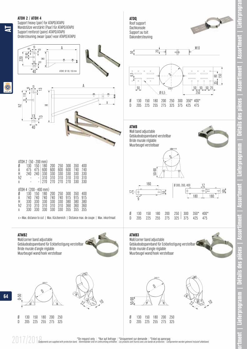
40ATOH 2 (50 - 200 mm)Ø 130 150 180 200 250 300 350 400 A 475 475 600 600 600 600 740 740 H 240 240 330 330 330 330 330 330 h2 - - 310 310 310 310 310 310x - - 270 270 270 270 330 330
ATOH 4 (200 - 400 mm)Ø 130 150 180 200 250 300 350 400 A 740 740 740 740 740 915 915 915 H 330 330 330 330 330 380 380 380 h2 310 310 310 310 310 360 360 360 x 330 330 330 330 330 355 355 355
x = Max. distance to cut | Max. Kürzbereich | Distance max. de coupe | Max. inkortmaat
ATOH2: Ø 130, 150 m
H
HA
A
x
1313
13
40 13
13
13
13
13
19
19
13
220
80
110
h2
13
HA
13
13
1319
13
220
80
13
40 ATOH2: Ø 130, 150 mm
150
3580
50 50 25250
50Ø 6,5
50
D6,550 20
M10
50-9
0D
55
160 12Ø 300, 350, 400
180 180
11 6012
9
50-9
0
D
1022
0-50
D
1022
ATOH 2 / ATOH 4Roof supportDachkonsoleSupport au toitDakondersteuning
Ø 130 150 180 200 250 300 350* 400*D 205 225 255 275 325 375 425 475
ATMBWall band adjustableGebäudeabspannband verstellbarBride murale réglableMuurbeugel verstelbaar
Ø 130 150 180 200 250 300 350* 400*D 205 225 255 275 325 375 425 475
ATMB3Wall/corner band adjustableGebäudeabspannband für Eckbefestigung verstellbarBride murale d’angle réglableMuurbeugel wand/hoek verstelbaar
Ø 130 150 180 200 250D 205 225 255 275 325
ATMB2Wall/corner band adjustableGebäudeabspannband für Eckbefestigung verstellbarBride murale d’angle réglableMuurbeugel wand/hoek verstelbaar
Ø 130 150 180 200 250D 205 225 255 275 325
64
AT
2017/2018 *On request only | *Nur auf Anfrage | |*Enkel op aanvraag Components are supplied with protection band. \ Klemmbänder sind im Lieferumfang enthalten. \ Les produits sont fournis avec une bande de protection. \ Componenten worden geleverd inclusief afdekband.

300-310
40-7
090
-160
1124255-400
75-1
7512
5-26
5
1124
465-755
175-
345
225-
435
1124A
ATMB
V2 9
0 - 20
0AT
MBV3
190
- 300
ATMB
V4 2
90 - 4
00
D
75
Ø 11
D
85
M10 3013
23
11
40
13
35
H
CB
A
ATMBAH1 99Distance block for ATMB 13-25
Contre-attache d’extension pour ATMB 13-25Afstandhouder verstelbaar voor ATMB 13-25
ATMBAH2 99Distance block for ATMB 13-25
Contre-attache d’extension pour ATMB 13-25Afstandhouder verstelbaar voor ATMB 13-25
ATMBAH3 99Distance block for ATMB 13-25
Contre-attache d’extension pour ATMB 13-25Afstandhouder verstelbaar voor ATMB 13-25
ATMBV2, ATMBV3, ATMBV4Wall band adjustableGebäudeabspannband verstellbarBride murale réglableMuurbeugel verstelbaar
Ø 130 150 180 200 250 300 350* 400*D 205 225 255 275 325 375 425 475A 235 255 285 305 355 405 455 505
ATMOBand for wall supportStutzband zu WandstützeBride pour support muralBand voor muurondersteuning
Ø 130 150 180 200 250D 205 225 255 275 325
ATOL 1 / ATOL 2Support light (pair) for ATMOWandstütze (Paar) für ATMOSupport léger (paire) ATMOOndersteuning licht (paar) voor ATMO
Ø 130 150 180 200 250A 285 285 285 285 285B 255 255 255 255 255C 130 130 130 130 130H 230 230 230 230 230
Ø 130 150 180 200 250
B 305 315 340 340 365C 180 200 215 215 240H 275 285 305 305 325
65
AT
2017/2018*On request only | *Nur auf Anfrage | |*Enkel op aanvraag Components are supplied with protection band. \ Klemmbänder sind im Lieferumfang enthalten. \ Les produits sont fournis avec une bande de protection. \ Componenten worden geleverd inclusief afdekband.
D
M6
D
150
150
340
A
H
DØ 6,5
30�-40�
745
A
ATIBS
ATIBVR
ATIBMT
ATIB 70
ATIBLS
ATIBMH
ATIBBH
ATIBAPH
ATIBMR
ATIBMD
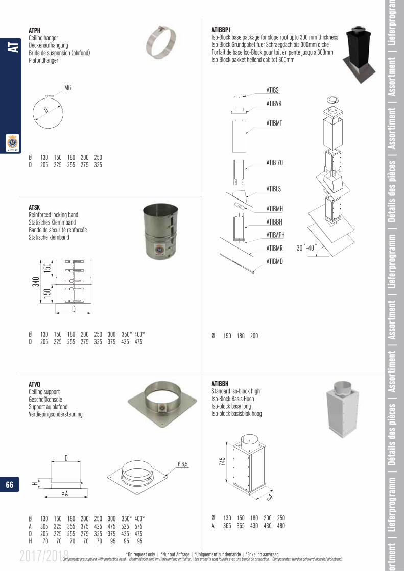
Ceiling hangerDeckenaufhängungBride de suspension (plafond)Plafondhanger
Ø 130 150 180 200 250D 205 225 255 275 325
Reinforced locking bandStatisches KlemmbandBande de sécurité renforcéeStatische klemband
Ø 130 150 180 200 250 300 350* 400*D 205 225 255 275 325 375 425 475
Ceiling supportGeschoßkonsoleSupport au plafondVerdiepingsondersteuning
Ø 130 150 180 200 250 300 350* 400*A 305 325 355 375 425 475 525 575D 205 225 255 275 325 375 425 475
Iso-Block base package for slope roof upto 300 mm thicknessIso-Block Grundpaket fuer Schraegdach bis 300mm dickeForfait de base Iso-Block pour toit en pente jusqu a 300mmIso-Block pakket hellend dak tot 300mm
Ø 150 180 200
ATIBBHStandard Iso-block highIso-Block Basis HochIso-block base longIso-block basisblok hoog
Ø 130 150 180 200 250A 365 365 430 430 480
66
AT
2017/2018 *On request only | *Nur auf Anfrage | |*Enkel op aanvraag Components are supplied with protection band. \ Klemmbänder sind im Lieferumfang enthalten. \ Les produits sont fournis avec une bande de protection. \ Componenten worden geleverd inclusief afdekband.
40�-50�
ATIBS
ATIBVR
ATIBMT
ATIBP10
ATIBBH
ATIBMH
ATIBAPH
ATIBMR
ATIBMD
A
390
300/
500/
700
A
ATIBS
ATIBVR
ATIBMT
ATIB 70
ATIBLE
ATIB 50
ATIBBH
ATIBMH
ATIBAPH
ATIBMR
ATIBMD
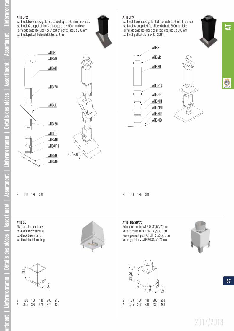
Iso-Block base package for slope roof upto 500 mm thicknessIso-Block Grundpaket fuer Schraegdach bis 500mm dickeForfait de base Iso-Block pour toit en pente jusqu a 500mmIso-Block pakket hellend dak tot 500mm
Ø 150 180 200
Iso-Block base package for flat roof upto 300 mm thicknessIso-Block Grundpaket fuer Flachdach bis 300mm dickeForfait de base Iso-Block pour toit plat jusqu a 300mmIso-Block pakket plat dak tot 300mm
Ø 150 180 200
ATIBBLStandard Iso-block lowIso-Block Basis NiedrigIso-block base courtIso-block basisblok laag
Ø 130 150 180 200 250A 325 325 375 375 430
ATIB 30/50/70Extension set for ATIBBH 30/50/70 cmVerlängerung für ATIBBH 30/50/70 cmProlongement pour ATIBBH 30/50/70 cmVerlengset t.b.v. ATIBBH 30/50/70 cm
Ø 130 150 180 200 250A 365 365 430 430 480
67
AT
2017/2018
1000
A
ABD
DA
B
A
10001215
Ø
50
325100
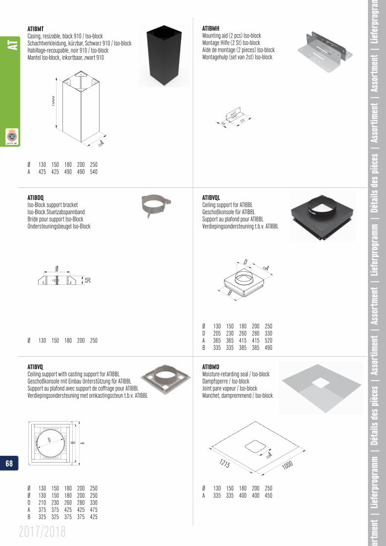
ATIBMT
Ø 130 150 180 200 250
ATIBMHMounting aid (2 pcs) Iso-blockMontage Hilfe (2 St) Iso-blockAide de montage (2 pieces) Iso-blockMontagehulp (set van 2st) Iso-block
Ceiling support for ATIBBLGeschoßkonsole für ATIBBLSupport au plafond pour ATIBBLVerdiepingsondersteuning t.b.v. ATIBBL
Ø 130 150 180 200 250D 205 230 260 280 330A 365 365 415 415 520
ATIBMDMoisture-retarding seal / Iso-blockDampfsperre / Iso-blockJoint pare vapeur / Iso-blockManchet, dampremmend / Iso-block
Ø 130 150 180 200 250A 335 335 400 400 450
Iso-Block support bracketIso-Block StuetzabspannbandBride pour support Iso-BlockOndersteuningsbeugel Iso-Block
Ø 130 150 180 200 250
Ceiling support with casting support for ATIBBL
Support au plafond avec support de coffrage pour ATIBBLVerdiepingsondersteuning met omkastingssteun t.b.v. ATIBBL
Ø 130 150 180 200 250Ø 130 150 180 200 250D 210 230 260 280 330A 375 375 425 425 475B 325 325 375 375 425
68
AT
2017/2018
A
D
B
D
A
A
1000 1215
D
A
B
D
A
B
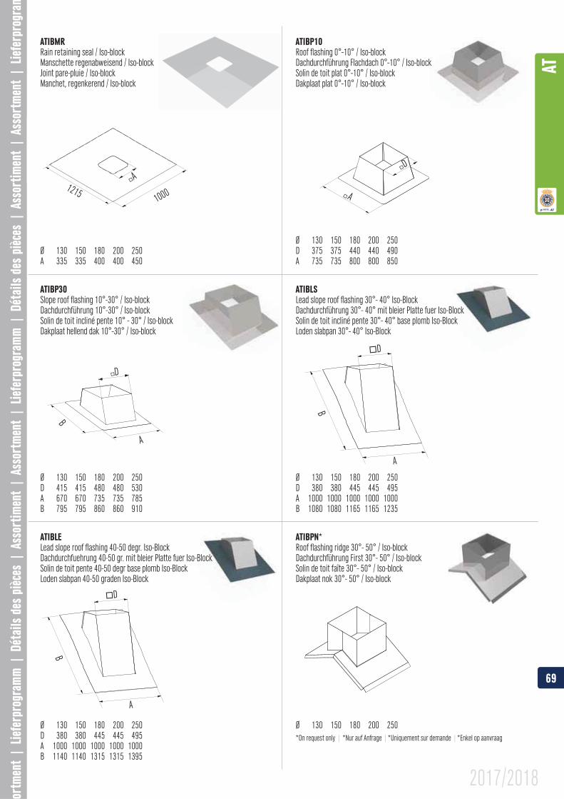
ATIBMRRain retaining seal / Iso-blockManschette regenabweisend / Iso-blockJoint pare-pluie / Iso-blockManchet, regenkerend / Iso-block
Ø 130 150 180 200 250A 335 335 400 400 450
Roof flashing 0°-10° / Iso-blockDachdurchführung Flachdach 0°-10° / Iso-blockSolin de toit plat 0°-10° / Iso-blockDakplaat plat 0°-10° / Iso-block
Ø 130 150 180 200 250
A 735 735 800 800 850
Slope roof flashing 10°-30° / Iso-blockDachdurchführung 10°-30° / Iso-blockSolin de toit incliné pente 10° - 30° / Iso-blockDakplaat hellend dak 10°-30° / Iso-block
Ø 130 150 180 200 250D 415 415 480 480 530A 670 670 735 735 785
ATIBLELead slope roof flashing 40-50 degr. Iso-BlockDachdurchfuehrung 40-50 gr. mit bleier Platte fuer Iso-BlockSolin de toit pente 40-50 degr base plomb Iso-BlockLoden slabpan 40-50 graden Iso-Block
Ø 130 150 180 200 250
A 1000 1000 1000 1000 1000
ATIBLSLead slope roof flashing 30°- 40° Iso-BlockDachdurchführung 30°- 40° mit bleier Platte fuer Iso-BlockSolin de toit incliné pente 30°- 40° base plomb Iso-BlockLoden slabpan 30°- 40° Iso-Block
Ø 130 150 180 200 250
A 1000 1000 1000 1000 1000B 1080 1080 1165 1165 1235
Roof flashing ridge 30°- 50° / Iso-blockDachdurchführung First 30°- 50° / Iso-blockSolin de toit faîte 30°- 50° / Iso-blockDakplaat nok 30°- 50° / Iso-block
Ø 130 150 180 200 250*On request only | *Nur auf Anfrage | |*Enkel op aanvraag
69
AT
2017/2018
A
A A
ø 8
D
D
Ø 8
D1 D2
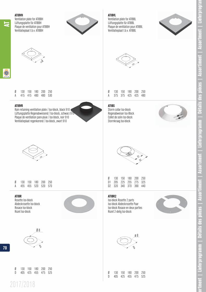
ATIBVR
Ø 130 150 180 200 250A 455 455 520 520 570
ATIBVLVentilation plate for ATIBBLLüftungsplatte für ATIBBLPlaque de ventilation pour ATIBBLVentilatieplaat t.b.v. ATIBBL
Ø 130 150 180 200 250A 375 375 425 425 480
ATIBVHVentilation plate for ATIBBHLüftungsplatte für ATIBBHPlaque de ventilation pour ATIBBHVentilatieplaat t.b.v. ATIBBH
Ø 130 150 180 200 250A 415 415 480 480 530
ATIBR2Iso-block Rosette 2 partsIso-block Abdeckrosette PaarIso-block Rosace en deux partiesRozet 2-delig Iso-block
Ø 130 150 180 200 250D 405 425 455 475 525
ATIBRRosette Iso-blockAbdeckrosette Iso-blockRosace Iso-blockRozet Iso-block
Ø 130 150 180 200 250D 405 425 455 475 525
ATIBSStorm collar Iso-blockRegenabweiser Iso-BlockCollet de solin Iso-blockStormkraag Iso-block
Ø 130 150 180 200 250D1 205 225 255 275 325
70
AT
2017/2018
ø 8
� A
ø 8
� A
D
120
20°-
A x B
H
D
A x B 5°- 30°
200
A x B
45°- 60°
D
A
D
B
315
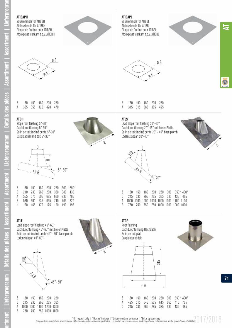
Square finish for ATIBBLAbdeckbende für ATIBBLPlaque de finition pour ATIBBLAfdekplaat vierkant t.b.v. ATIBBL
Ø 130 150 180 200 250A 315 315 365 365 425
Square finish for ATIBBHAbdeckbende für ATIBBHPlaque de finition pour ATIBBHAfdekplaat vierkant t.b.v. ATIBBH
Ø 130 150 180 200 250A 355 355 420 420 470
ATLSLead slope roof flashing 20°-45°Dachdurchführung 20°-45° mit bleier PlatteSolin de toit incliné pente 20° - 45° base plombLoden slabpan 20°-45°
Ø 130 150 180 200 250 300 350* 400*D 215 235 265 285 335 385 435 485 A 1000 1000 1000 1000 1000 1000 1100 1100B 750 750 750 750 1000 1000 1000 1000
ATDHSlope roof flashing 5°-30°Dachdurchführung 5°-30°Solin de toit incliné pente 5°-30°Dakplaat hellend dak 5°-30°
Ø 130 150 180 200 250 300 350*D 210 230 260 280 330 380 430A 555 575 605 625 680 730 785B 580 600 635 635 710 765 820
BB
ATLELead slope roof flashing 45°-60°Dachdurchführung 45°-60° mit bleier PlatteSolin de toit incliné pente 45° - 60° base plombLoden slabpan 45°-60°
Ø 130 150 180 200 250D 215 235 265 285 335A 1000 1000 1100 1200 1300 B 750 750 750 1000 1000
B
Roof flashingDachdurchführung FlachdachSolin de toit platDakplaat plat dak
Ø 130 150 180 200 250 300 350* 400*
D 215 235 265 285 335 385 435 485
71
AT
2017/2018*On request only | *Nur auf Anfrage | |*Enkel op aanvraag Components are supplied with protection band. \ Klemmbänder sind im Lieferumfang enthalten. \ Les produits sont fournis avec une bande de protection. \ Componenten worden geleverd inclusief afdekband.
D70
D
550
450
550450
455
520
555
620
450
130
400
900
0-45°
B
z
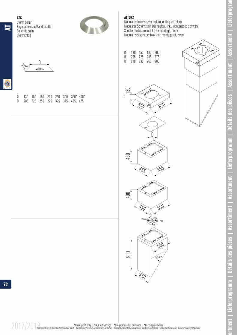
ATSStorm collarRegenabweiser/WandrosetteCollet de solinStormkraag
Ø 130 150 180 200 250 300 350* 400*D 205 225 255 275 325 375 425 475
Modular chimney cover incl. mounting set, blackModularer Schornstein Dachaufbau inkl. Montageset, schwarzSouche modulaire incl. kit de montage, noireModulair schoorsteenblok incl. montageset, zwart
Ø 130 150 180 200B 205 225 255 275D 210 230 260 280
72
AT
2017/2018 *On request only | *Nur auf Anfrage | |*Enkel op aanvraag Components are supplied with protection band. \ Klemmbänder sind im Lieferumfang enthalten. \ Les produits sont fournis avec une bande de protection. \ Componenten worden geleverd inclusief afdekband.
H
Ø
Ø
H
A
H1
Ø
A
H
A
HH1
D
Ø
H
A
Ø
H
AG
Ø
H
A
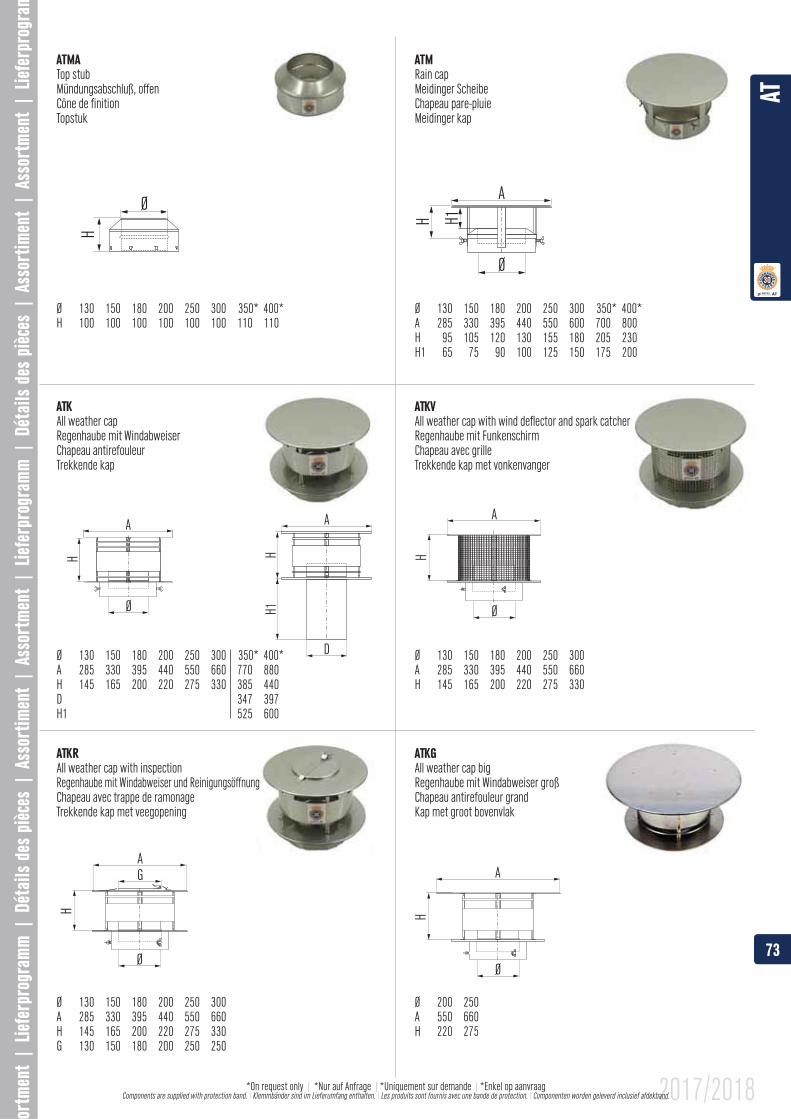
ATMATop stubMündungsabschluß, offenCône de finitionTopstuk
Ø 130 150 180 200 250 300 350* 400*H 100 100 100 100 100 100 110 110
All weather capRegenhaube mit WindabweiserChapeau antirefouleurTrekkende kap
Ø 130 150 180 200 250 300 350* 400*
H 145 165 200 220 275 330 385 440
H1 525 600
All weather cap with wind deflector and spark catcherRegenhaube mit FunkenschirmChapeau avec grilleTrekkende kap met vonkenvanger
Ø 130 150 180 200 250 300
H 145 165 200 220 275 330
ATMRain capMeidinger ScheibeChapeau pare-pluieMeidinger kap
Ø 130 150 180 200 250 300 350* 400*
All weather cap with inspectionRegenhaube mit Windabweiser und ReinigungsöffnungChapeau avec trappe de ramonageTrekkende kap met veegopening
Ø 130 150 180 200 250 300
H 145 165 200 220 275 330G 130 150 180 200 250 250
All weather cap bigRegenhaube mit Windabweiser großChapeau antirefouleur grandKap met groot bovenvlak
Ø 200 250A 550 660H 220 275
73
AT
2017/2018*On request only | *Nur auf Anfrage | |*Enkel op aanvraag Components are supplied with protection band. \ Klemmbänder sind im Lieferumfang enthalten. \ Les produits sont fournis avec une bande de protection. \ Componenten worden geleverd inclusief afdekband.
Ø
H1
H
A
D
100
55
Ø
H
A
Ø
7555
375 375 375
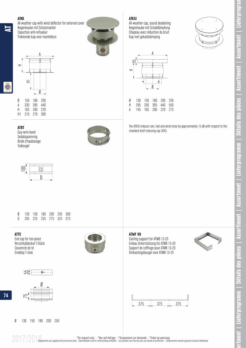
All weather cap with wind deflector for external coverRegenhaube mit SchutzmantelCapuchon anti-refouleurTrekkende kap voor mantelbuis
Ø 150 180 200
H 165 200 220H1 210 270 300
ATBTGuy-wire bandSeilabspannringBride d’haubanageTuibeugel
Ø 130 150 180 200 250 300D 205 225 255 275 325 375
All weather cap, sound deadeningRegenhaube mit SchalldämpfungChapeau avec réduction du bruitKap met geluidsdemping
Ø 130 150 180 200 250
A 145 165 200 220 275
The ATKSI reduces rain, hail and wind noise by approximately 15 dB with respect to the standard draft inducing cap (ATK).
ATTEEnd cap for tee-pieceVerschlußdeckel T-StückCouvercle de téEinddop T-stuk
Ø 130 150 180 200 250
ATMF 99Casting support for ATMB 13-20
Support de coffrage pour ATMB 13-20Omkastingsbeugel voor ATMB 13-20
74
AT
2017/2018 *On request only | *Nur auf Anfrage | |*Enkel op aanvraag Components are supplied with protection band. \ Klemmbänder sind im Lieferumfang enthalten. \ Les produits sont fournis avec une bande de protection. \ Componenten worden geleverd inclusief afdekband.
1”
40
max. 250min. 80
� 78
max
. 155
0m
in. 3
00
� D
EN �AT �
130
D
CA
B
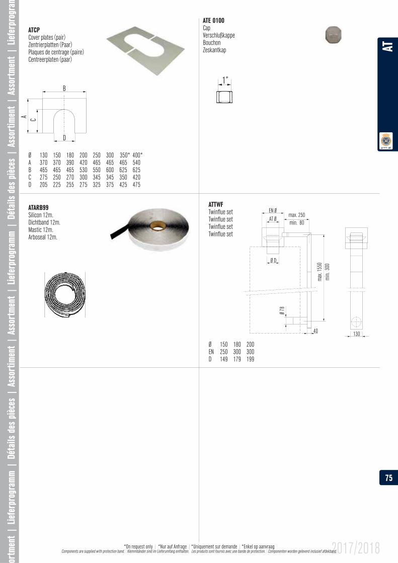
ATE 0100CapVerschlußkappeBouchonZeskantkap
ATARB99Silicon 12m.Dichtband 12m.Mastic 12m.Arboseal 12m.
Cover plates (pair)Zentrierplatten (Paar)Plaques de centrage (paire)Centreerplaten (paar)
Ø 130 150 180 200 250 300 350* 400*
B 465 465 465 530 550 600 625 625C 275 250 270 300 345 345 350 420D 205 225 255 275 325 375 425 475
ATTWFTwinflue setTwinflue setTwinflue setTwinflue set
Ø 150 180 200EN 250 300 300
75
AT
2017/2018*On request only | *Nur auf Anfrage | |*Enkel op aanvraag Components are supplied with protection band. \ Klemmbänder sind im Lieferumfang enthalten. Les produits sont fournis avec une bande de protection. \ Componenten worden geleverd inclusief afdekband.
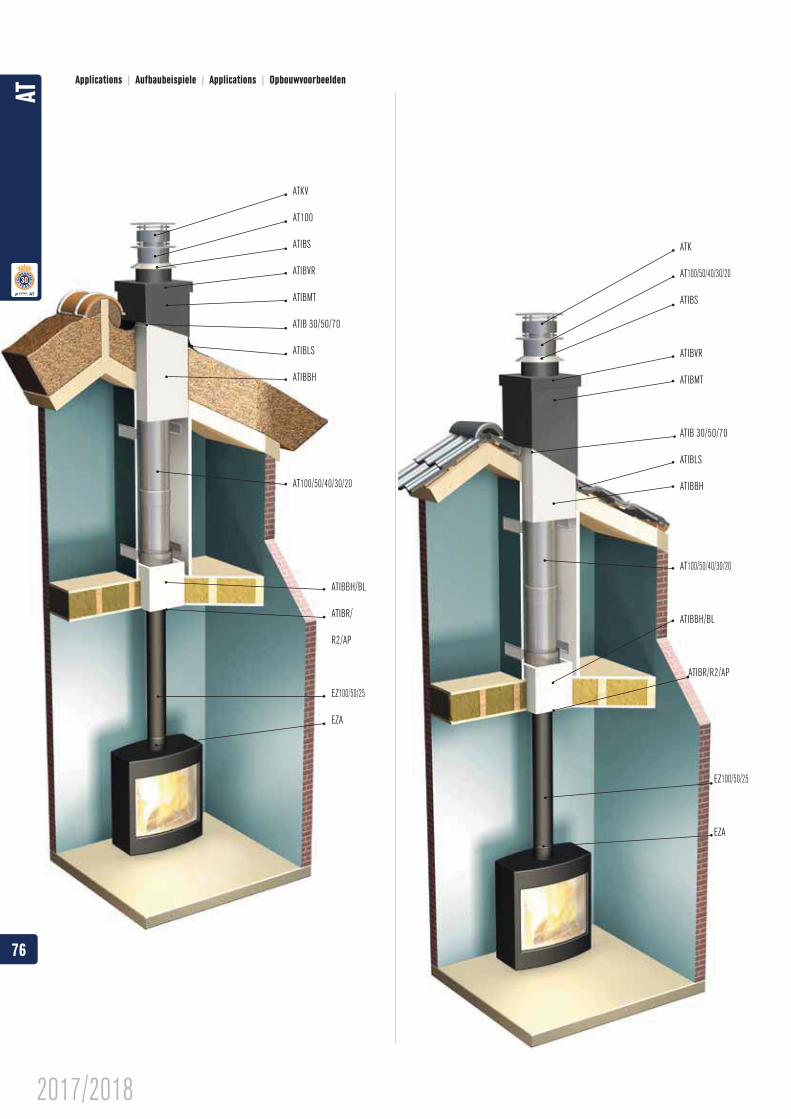
ATKV
AT100
ATIBS
ATIBVR
ATIBMT
ATIB 30/50/70
ATIBLS
ATIBBH
AT100/50/40/30/20
ATK
AT100/50/40/30/20
ATIBS
ATIBVR
ATIBMT
ATIB 30/50/70
ATIBLS
ATIBBH
AT100/50/40/30/20
ATIBBH/BL
ATIBR/R2/AP
ATIBBH/BL
ATIBR/
R2/AP
EZ100/50/25
EZA
EZ100/50/25
EZA
Applications | Aufbaubeispiele | Applications | Opbouwvoorbeelden
76
AT
2017/2018
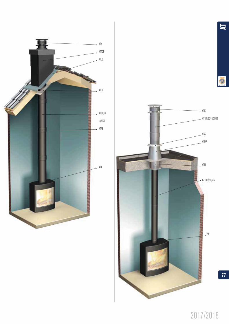
ATK
ATTOP
ATLS
ATCP
AT100/50/
40/30/20
ATAB
ATA
ATK
AT100/50/40/30/20
ATS
ATDP
ATN
EZ100/50/25
EZA
77
AT
2017/2018
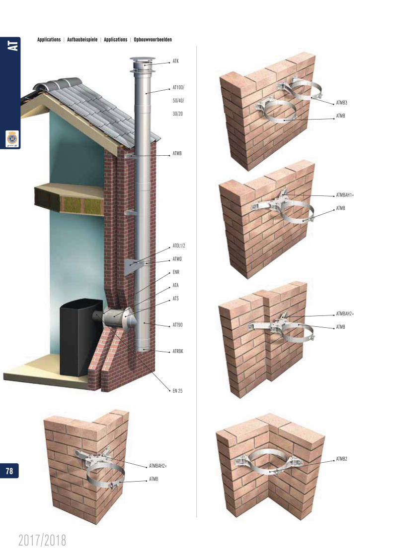
ATK
AT100/
50/40/
30/20
ATMB
ATOL1/2
ATMO
ENR
ATA
ATS
ATRBK
EN 25
ATMB3
ATMB
ATMBAH1+
ATMB
ATMBAH2+
ATMB
ATMB2ATMBAH2+
ATMB
Applications | Aufbaubeispiele | Applications | Opbouwvoorbeelden
78
AT
2017/2018
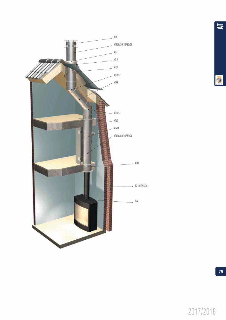
ATK
AT100/50/40/30/20
ATS
ATLS
ATDQ
ATB45
ATPP
ATB45
ATVQ
ATMB
AT100/50/40/30/20
ATN
EZ100/50/25
EZA
79
AT
2017/2018
WE CARE
Ontop B.V.Postbus 135, 4330 AC Middelburg Oude Veerseweg 23, 4332 SH MiddelburgNederland
Ontop Abgastechnik GmbHAlbert-Einstein-Straße 851674 WiehlDeutschland
Metaloterm France S.A.R.L.65, Avenue du Général de Gaulle77420 Champs-sur-MarneFranceT : +33 (0)1 64 62 12 30F : +33 (0)1 64 62 11 08E : [email protected]
ul. Hallera 75
PolskaT : +48 (0)43 676 33 66
AT

![Catalogus - Musées de Marseille...Catalogus. bulletin bibliographique. Le Centre de documentation Ernst Goldschmidt, bibliothèque du [mac] musée d'art contemporain de Marseille,](https://img.pdfslide.fr/doc/110x75/60afb92d91213a1e803bfab1/catalogus-muses-de-marseille-catalogus-bulletin-bibliographique-le-centre.jpg)