Embed Size (px)
Citation preview

C O N T E N T SC O N T E N T S
CATALOGCATALOG
Corporation27, Zusho Baba, Nagaokakyo-shi Kyoto Japan
(Fuji DIC Bldg.) 2-12-2, Taito, Taito-ku, Tokyo
(ITOH bldg.)2-13-22, Iseyama, Naka-ku, Nagoya
(Shinmachi Bldg.) 1-2-13, Shinmachi, Nishi-ku, Osaka
366-1, Hishikawa-cho, Hazukashi, Fushimiku, Kyoto
366-1, Hishikawa-cho, Hazukashi, Fushimiku, Kyoto
Phone:075-955-0071
Phone:03-3833-5330
Phone:052-322-3481
Phone:06-6538-7136
Phone:075-924-3293
Phone:075-931-2731
Fax:075-955-1063
Fax:03-3833-5350
Fax:052-322-3483
Fax:06-6538-7138
Fax:075-924-3290
Fax:075-934-8746
Head Office
Tokyo Branch
Nagoya Branch
Osaka Branch
Kyoto Branch
Fushimi Works
1. NKE's Ideas for Production Systems
2. Product Lineup
3. How to Order
4. Product Introductions
Parts Handling Instruments
Air Grippers
Slide Cylinders
Rotary Actuators
Conveyor Instruments
Conveyors
Stopper and Escapement Units
Wire-Saving Instruments UNILINE
UN Series
H Series and Others
4
9
10
11
22
23
24
25
1
2
3
NKE's Ideas for Production Systems
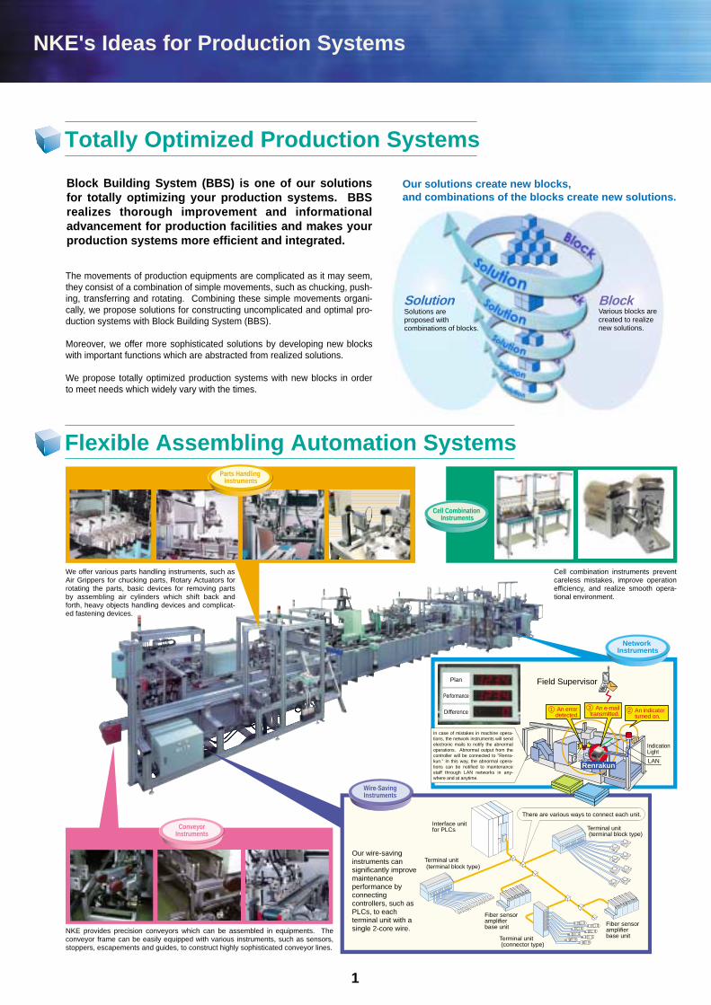
Block Building System (BBS) is one of our solutions for totally optimizing your production systems. BBS realizes thorough improvement and informational advancement for production facilities and makes your production systems more efficient and integrated.
Totally Optimized Production Systems
Flexible Assembling Automation Systems
The movements of production equipments are complicated as it may seem, they consist of a combination of simple movements, such as chucking, push-ing, transferring and rotating. Combining these simple movements organi-cally, we propose solutions for constructing uncomplicated and optimal pro-duction systems with Block Building System (BBS).
Moreover, we offer more sophisticated solutions by developing new blocks with important functions which are abstracted from realized solutions.
We propose totally optimized production systems with new blocks in order to meet needs which widely vary with the times.
Our solutions create new blocks, and combinations of the blocks create new solutions.
Our wire-saving instruments can significantly improve maintenance performance by connecting controllers, such as PLCs, to each terminal unit with a single 2-core wire.
Terminal unit (terminal block type)
Interface unit for PLCs
Terminal unit (terminal block type)
Terminal unit (connector type)
Fiber sensor amplifier base unit
Fiber sensor amplifier base unit
There are various ways to connect each unit.
Solutions are proposed with combinations of blocks.
Various blocks are created to realize new solutions.
Solution Block
An errordetected.
LAN
Indication Light
Field Supervisor
1
We offer various parts handling instruments, such as Air Grippers for chucking parts, Rotary Actuators for rotating the parts, basic devices for removing parts by assembling air cylinders which shift back and forth, heavy objects handling devices and complicat-ed fastening devices.
NKE provides precision conveyors which can be assembled in equipments. The conveyor frame can be easily equipped with various instruments, such as sensors, stoppers, escapements and guides, to construct highly sophisticated conveyor lines.
Cell combination instruments prevent careless mistakes, improve operation efficiency, and realize smooth opera-tional environment.
Wire-SavingInstruments
Cell Combination Instruments
Network Instruments
In case of mistakes in machine opera-tions, the network instruments will send electronic mails to notify the abnormal operations. Abnormal output from the controller will be connected to "Renra-kun." In this way, the abnormal opera-tions can be notified to maintenance staff through LAN networks in any-where and at anytime.
Renrakun
1 23
Parts Handling Instruments
Plan
Performance
Difference
ConveyorInstruments
An e-mailtransmitted.
An indicatorturned on.
Product Lineup
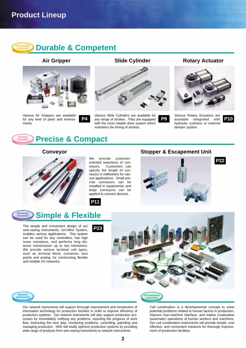
Our network instruments will support thorough improvement and introduction of information technology for production facilities in order to improve efficiency of production systems. Our network instruments will also support production pro-cesses by immediately notifying any problems, reporting the progress of work flow, instructing the next step, monitoring problems, controlling, patrolling and managing production. NKE will totally optimize production systems by providing wide range of products from wire-saving instruments to network instruments.
We provide customer-oriented selections of con-veyors. Customers can specify the length of con-veyors in millimeters for vari-ous applications: Small pre-cise conveyors can be installed in equipments; and large conveyors can be applied to connect devices.
Cell combination is a developmental concept to solve potential problems related to human factors in production, improve man-machine interface, and realize cooperative (automatic) operations of human workers and machines. Our cell combination instruments will provide simple, cost effective, and convenient solutions for thorough improve-ment of production facilities.
Conveyor Stopper & Escapement Unit
Durable & Competent
Precise & Compact
P11
P23
P22
P4 P9 P10
2
Simple & Flexible
Various Air Grippers are available for any kind of parts and environ-ments.
Various Slide Cylinders are available for any range of strokes. They are equipped with the most reliable drive system which maintains the timing of strokes.
Various Rotary Actuators are available integrated with hydraulic cushions or external damper system.
Air Gripper Slide Cylinder Rotary Actuator
The simple and convenient design of our wire-saving instruments, Uni-Wire System, enables various applications. This system can be used for any controllers, has high noise resistance, and performs long dis-tance transmission up to two kilometers. We provide various terminal unit types, such as terminal block, connector, less points and analog, for constructing flexible and reliable I/O networks.
Parts Handling Instruments
ConveyorInstruments
Wire-SavingInstruments
Cell Combination Instruments
Network Instruments
UNILINE
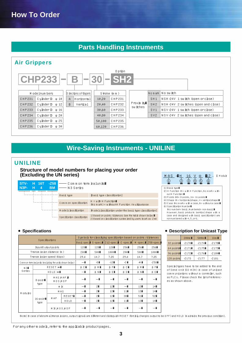
How To Order
3
Parts Handling Instruments
Air Grippers
Model numbers Directions of fingers
Proximity�switches
CHP231 CHP231 SH1
No mark
SH2
SV1
SV2
NSH-24V 1 switch (open or close)
No switch
NSH-24V 2 switches (open and close)
NSV-24V 1 switch (open or close)
NSV-24V 2 switches (open and close)
Stroke (mm)
10,20
CHP232
CHP233
CHP234
CHP235
CHP236
20,40
30,60
40,80
50,100
60,120
A
B
Horizontal
VerticalCHP232
CHP233
CHP234
CHP235
CHP236
Cylinder ID φ10
Cylinder ID φ12
Cylinder ID φ16
Cylinder ID φ20
Cylinder ID φ25
Cylinder ID φ30
Option
B 30 SH2CHP233
UNILINE
MAS -�H 16 V □ �12 … IC Module①� ②� ③� ④� ⑤� ⑥�STV- H 16T -Z58
N3P- H 4 BMCommon terminal units�N3 Series
Basic type
Common specification H = with H Function�(No mark) = without H Function / multipurpose
[Model classification under the basic type classification]
1) Based on points / distances (see the table shown below)�2) Based on classification customized by users (mark as -Z**)
Model classification
Specification classification
[Basic type classification]
Structure of model numbers for placing your order (Excluding the UN series)
Special types have to be added to the end of Send Unit (SD-H2A) in case of unicast communications without a controller, such as PLCs. Please check the list of referenc-es as shown above.
32 points�
64 points�
96 points�
128 points
200m�
-Z170�
-Z171�
-Z172�
-Z173
500m�
-Z174�
-Z175�
-Z176�
-Z177
1km�
-Z178�
-Z179�
-Z180�
-Z181
●Specifications ●Description for Unicast Type
Basic spec.�
128�
200�
29.4
-�
βC�
-�
-�
-�
-�
-�
-�
-�
-S�
βM�
βN�
-�
2�
2�
2�
2�
-�
-12�
βF�
βE�
-�
12�
12�
12�
12�
-�
-Z58�
βF�
βE�
-�
14�
14�
52�
14�
-�
-C�
βC�
βD�
-�
-�
11�
38�
11�
-�
-M�
βM�
βN�
-�
13�
13�
51�
13�
-�
S-spec.�
128�
500�
14.7
Z12-spec.�
128�
1000�
7.35
Symbols for classifying specification based on points / distancesSpecifications
Input/Output points
Transmission distance (m)
Transmission speed (kbps)
Common terminal units (excluding the units shown below)
C-spec.�
256�
200�
29.4
M-spec.�
256�
500�
14.7
Z58-spec.�
256�
1000�
7.35
RESET�
HOLD
RESET *�
HOLD *�N3�Series
Modules
8-point�type
16-point�type
MAS,MAP,�MOS,MOP
MIX,MOS,MOP
MIX
MAS
MAP
(Note) In case of abnormal transmissions, output signals are different and distinguish RESET (forcibly changes output to be OFF) and HOLD (maintains the previous condition).
For any other models, refer to the applicable product pages.
Wire-Saving Instruments - UNILINE
(1) Basic type�(2) H Function (H= with H Function, No mark= with-out H Function)�
(3) Points (08= 8 points, 16= 16 points)�(4) Shape (H= horizontal shape, V= vertical shape)�(5) Case (No mark= with a case, N= without a case)�(6) Specification Number�(No number= basic, Numbered= non-basic)�However, basic products (vertical shape with a case and designed with basic specification) are not numbered with 4, 5, or 6.
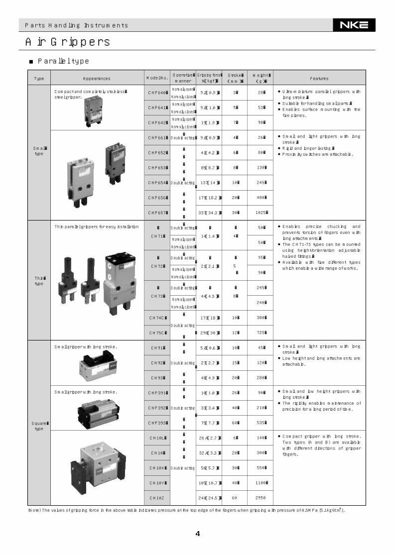
Parts Handling Instruments
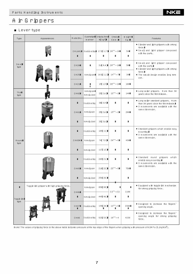
Air Grippers
(Note) The values of gripping force in the above table indicates pressure at the top edge of the fingers when gripping with pressure of 0.5MPa {5.1kgf/c㎡}.
Features
●Ultra-miniature parallel grippers with long stroke.�●Suitable for handling small parts.�●Enables surface mounting with the five planes.
●Small and light grippers with long stroke.�●Rigid and longer lasting.�●Proximity switches are attachable.
●Enables precise chucking and prevents torsion of fingers even with long attachments.�●The CH71-73 types can be mounted using height/orientation adjustable halved fittings.�●Available with five different types which enable a wide range of works.
●Compact gripper with long stroke. Two types (A and B) are available with different directions of gripper fingers.
●Small and low height grippers with long stroke.�●The rigidity enables maintenance of precision for a long period of time.
●Small and light grippers with long stroke.�●Low height and long attachments are attachable.
Appearances Model No. Weight �(g)�Type
Small�type
Square�type
Thin�type
Compact and completely stainless�steel gripper.
CHP640�
CHP641�
CHP642�
CHP661�
CHP652�
CHP653�
CHP654�
CHP656�
CHP657�
�
CH71�
�
CH72�
�
CH73�
CH74C�
CH75C�
CH91�
CH92�
CH93�
CHP391�
CHP392�
CHP393�
CH10L�
CH10�
CH10X�
CH10Y�
CH10Z
Operative�manner
Normally open�
Normally closed�
Normally open�
Normally closed�
Normally open�
Normally closed�
�Double acting�
�
�
�
�
�Double acting
�
�
�
�
�
�Double acting�
Normally open�
Normally closed�
�Double acting
�
Normally open�
Normally closed�
�Double acting�
Normally open�
Normally closed�
�
Double acting
��
�
�
Double acting�
�
�
�
�
Double acting
��
�
�
�
�
�
Double acting
28�
53�
98�
26�
80�
130�
245�
480�
1025�
50�
50�
95�
90�
245�
240�
380�
725�
45�
120�
280�
90�
210�
535�
140�
300�
550�
1100�
2950
Thin parallel grippers for easy installation
Small gripper with long stroke.
Small gripper with long stroke.
Stroke�(mm)�
3�
5�
7�
4�
6�
8�
10�
20�
30�
�
4�
�
5�
�
8�
10�
12�
10�
15�
20�
26�
40�
60�
6�
20�
30�
40�
60
Gripping force�N{kgf}�
9.2{0.9}�
9.8{1.0}�
19{1.9}�
9.8{0.9}�
41{4.2}�
85{8.7}�
137{14}�
179{18.2}�
337{34.3}�
�
14{1.4}�
�
21{2.1}�
�
44{4.5}�
173{18}�
298{30}�
5.8{0.6}�
27{2.7}�
48{4.9}�
10{1.0}�
33{3.4}�
75{7.7}�
26.4{2.7}�
32.4{3.3}�
56{5.7}�
105{10.7}�
240{24.5}�
■Parallel type
Parts Handling Instruments
Air Grippers
10�20�20�40�30�60�40�80�50�100�60�120�30�60�40�80�50�100�60�120�13�26�13�26�
26��30��40��20��20��30��
36���
19���
30��40��60��70��80��15��20��30��35��40
185�200�310�360�500�600�1165�1435�2015�2400�3075�3610�660�820�1020�1330�1750�2450�4140�5670�190�260�130�170�
1090��900��
2100��350��425��750��
1530���850���
1000��
1850��
3950��
6800��
9500��
1000��
1850��
3700��
6800��
9000
27{2.8}�
50{5.1}�
103{10.5}�
138{14}�
242{25}�
390{40}�
99{10}�
161{16}�
291{30}�
672{69}�
125{12.8}�
125{12.8}�
364{37.1}�
53{5.4}�
107{11}�
14{1.4}�
47{4.8}�
70{7.1}�
109{11}�
97{9.9}��
268{27.3}�
432{44}�
917{93.5}�
1121{114.3}�
1488{151.7}�
535{54.6}�
863{88}�
1833{187}�
2242{228.6}�
2975{303.5}�
�
CHP231�
CHP232�
CHP233�
CHP234�
CHP235�
CHP236�
CHP302�
CHP303�
CHP304�
CHP306�
CHP383-AL�
CHP383-PET�
CHP386-AL�
CH13S�
CH14S�
CH11�
CH12L�
CH12�
CH12X�
CH51��
CHP684�
CHP685�
CHP686�
CHP687�
CHP688�
CHP684S�
CHP685S�
CHP686S�
CHP687S�
CHP688S
Double acting
Double acting
Double acting
Double acting
Double acting
Double acting
Double acting
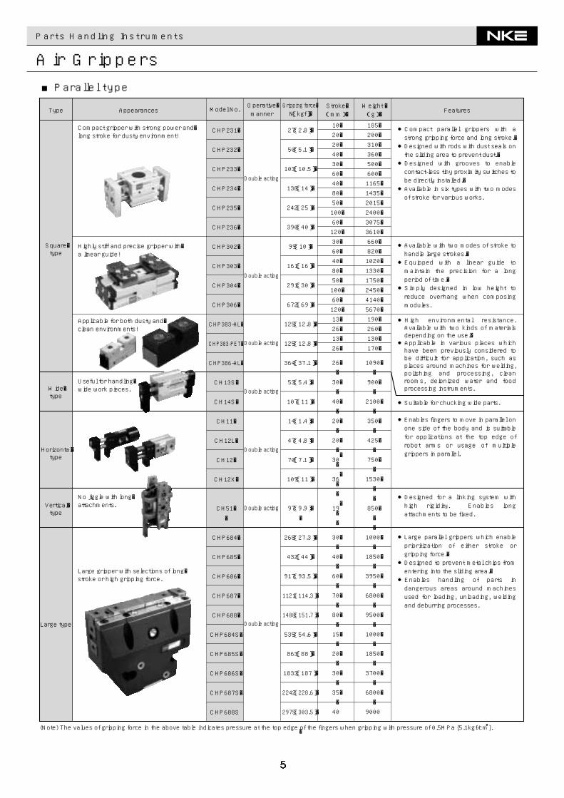
(Note) The values of gripping force in the above table indicates pressure at the top edge of the fingers when gripping with pressure of 0.5MPa {5.1kgf/c㎡}.
Square�type
Horizontal�type
Vertical�type
Large type
Wide�type
Compact gripper with strong power and�long stroke for dusty environment!
Applicable for both dusty and�clean environments!
Highly stiff and precise gripper with�a linear guide!
Useful for handling�wide work pieces.
No jiggle with long�attachments.
Large gripper with selections of long�stroke or high gripping force.
●Compact parallel grippers with a strong gripping force and long stroke.�●Designed with rods with dust seals on the sliding area to prevent dust.�●Designed with grooves to enable contact-less tiny proximity switches to be directly installed.�●Available in six types with two modes of stroke for various works.
●Available with two modes of stroke to handle large strokes.�●Equipped with a linear guide to maintain the precision for a long period of time.�●Simply designed in low height to reduce overhang when composing modules.
●High environmental resistance. Available with two kinds of materials depending on the use.�●Applicable in various places which have been previously considered to be difficult for application, such as places around machines for welding, polishing and processing, clean rooms, deionized water and food processing instruments.
●Suitable for chucking wide parts.
●Enables fingers to move in parallel on one side of the body and is suitable for applications at the top edge of robot arms or usage of multiple grippers in parallel.
●Designed for a linking system with high rigidity. Enables long attachments to be fixed.
●Large parallel grippers which enable prioritization of either stroke or gripping force.�●Designed to prevent metal chips from entering into the sliding area.�●Enables handling of parts in dangerous areas around machines used for loading, unloading, welding and deburring processes.
FeaturesAppearances Model No. Weight �(g)�Type
Operative�manner
Stroke�(mm)�
Gripping force�N{kgf}�
■Parallel type
Parts Handling Instruments
Air Grippers
CHT502�
CHT503�
CHT504�
CHT505�
CHT506�
CHT507�
CHT509�
CHT510�
CH81�
CH82�
CH83�
CHT525�
CHT527�
CHT528�
CHT529�
CHT525S�
CHT527S�
CHT528S�
CHT529S�
CH121�
CH122�
CH123�
CHW231�
CHW232�
CHW233�
CHW234�
CHW235�
CHW236
44{4.5}�
71{7.2}�
95{9.7}�
126{13}�
182{19}�
382{39}�
885{90}�
1575{161}�
82{8.3}�
181{18}�
348{35}�
525{53.6}�
1056{107.7}�
1365{139.2}�
2214{225.8}�
1050{107.1}�
2112{215.4}�
2730{278.5}�
4428{451.6}�
450{46}�
762{78}�
1528{156}�
52{5.3}�
90{9.2}�
194{20}�
263{27}�
414{42}�
696{71}�
4�
5�
6�
8�
10�
12�
20�
25�
6�
8�
10�
30�
40�
60�
70�
15�
20�
30�
35�
20�
30�
40�
10�
20�
30�
40�
50�
60
40�
62�
100�
142�
242�
365�
1030�
1920�
210�
410�
720�
2100�
3150�
6500�
12000�
1850�
2950�
6000�
11500�
2500�
4600�
7900�
370�
620�
1100�
2500�
5160�
7800
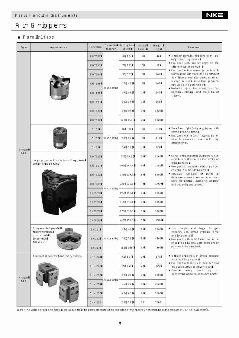
●3-finger parallel grippers with low height and long stroke.�●Equipped with two air ports on the side and top of the body.�●Equipped with a scavenge port which works as an air intake to blow off dust from fingers, and also works as an air suction to inhale dust from grippers. Applicable in clean rooms.�●Detect at up to four areas, such as opening, closing, and chucking of fingers.
●Large 3-finger parallel grippers which enable prioritization of either stroke or gripping force.�●Designed to prevent metal chips from entering into the sliding area.�●Enables handling of parts in dangerous areas around machines used for loading, unloading, welding and deburring processes.
●Small and light 3-finger grippers with strong gripping force.�●Equipped with a long finger guide for smooth movement even with long attachments.
●Low height and large 3-finger grippers with strong gripping force and long stroke.�●Designed with a hollowed center to enable air blowers, work detectors or pushers to be attached.
●4-finger grippers with strong gripping force and long stroke.�●Equipped with rods with dust seals at the sliding areas to prevent dust.�●Enable easy positioning or transferring of round or square parts.
(Note) The values of gripping force in the above table indicates pressure at the top edge of the fingers when gripping with pressure of 0.5MPa {5.1kgf/c㎡}.
3-finger�type
4-finger�type
Large gripper with selection of long stroke�or high gripping force.
Gripper with 3-parallel�fingers for fixing�attachments�longer than�100 mm.
The best gripper for handling cylinders.
FeaturesAppearances Model No. Weight �(g)�Type
Operative�manner
Stroke�(mm)�
Gripping force�N{kgf}�
Double acting
Double acting
Double acting
Double acting
Double acting
■Parallel type
Parts Handling Instruments
Air Grippers
CHL601�
�
CH20�
CH25�
CH21�
CH02�
�
CH01�
�
�
CH03M�
�
�
CH03�
�
CH06�
�
CH07��
CH08
17.5{1.7}�
�
3.8{0.4}�
10.5{1.1}�
19{1.9}�
25{2.6}�
38{3.9}�
25{2.6}�
35{3.6}�
109{11}�
74{7.5}�
117{12}�
209{21}�
218{22}�
254{26}�
858{88}�
449{46}�
199{20}��
523{53}�
20~-10�
�
20~-10�
14~-7�
20~-10�
15~-2�
�
19~-2�
�
�
20~-5�
�
�
25~-5�
�
2.5~-2.5
�
�
13~-5��
18~-4
54�
�
50�
34�
100�
140�
�
200�
�
�
430�
�
�
750�
�
1100
�
�
2300��
4150
Double acting�
�
�
Normally open�
��
Normally open�
Normally closed
●Small and light gripper composed with few parts.�●Slender and light grippers with strong force.�●The simple design enables long term use.
●Long-seller grippers. More than 30 years since the first release.
●Long-seller standard grippers. More than 30 years since the first release.�●3 movements are available with the same dimension.
●Standard grippers which enable easy mounting.�●3 movements are available with the same dimension.
●Standard round grippers which enable easy mounting.�●3 movements are available with the same dimension.
●Slender and light grippers with strong force.�●Small and light gripper composed with few parts.
●Equipped with toggle-link mechanism for strong gripping force.
●Designed to increase the fingers’ opening angle.
●Designed to increase the fingers’ opening angle for strong gripping force.
(Note) The values of gripping force in the above table indicates pressure at the top edge of the fingers when gripping with pressure of 0.5MPa {5.1kgf/c㎡}.
Small�type
Thin�type
Round�type
�
Toggle-link�type
Toggle-link gripper with high gripping force.
FeaturesAppearances Model No. Weight �(g)�Type
Operative�manner
Stroke�(mm)�
Gripping force�N{kgf}�
Double acting
Double acting
Normally closed
Normally open
Normally closed
Normally open
Double acting
Double acting
Double acting
Normally closed
Normally open
Normally closed
Normally open
■Lever type
Parts Handling Instruments
Air Grippers
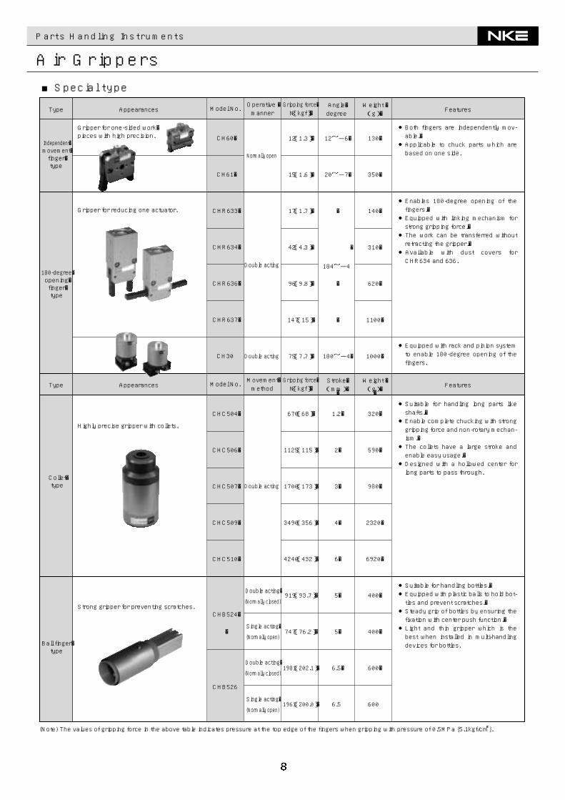
CH60�
CH61�
CHR633�
CHR634�
CHR636�
CHR637�
CH30
12{1.3}�
15{1.6}�
17{1.7}�
42{4.3}�
96{9.8}�
147{15}�
75{7.7}�
12~-6�
20~-7�
�
184~-4
�
�
�
180~-4�
�
130�
350�
140�
310�
620�
1100�
1000�
�
320�
590�
980�
2320�
6920�
400�
400�
600�
600
CHC504�
CHC506�
CHC507�
CHC509�
CHC510�
CHB524�
�
CHB526
670{68}�
1125{115}�
1700{173}�
3490{356}�
4240{432}�
919{93.7}�
747{76.2}�
1981{202.1}�
1961{200.0}�
1.2�
2�
3�
4�
6�
5�
5�
6.5�
6.5
●Both fingers are independently mov-able.�●Applicable to chuck parts which are based on one side.
●Enables 180-degree opening of the fingers.�●Equipped with linking mechanism for strong gripping force.�●The work can be transferred without retracting the gripper.�●Available with dust covers for CHR634 and 636.
●Equipped with rack and pinion system to enable 180-degree opening of the fingers.
●Suitable for handling bottles.�●Equipped with plastic balls to hold bot-tles and prevent scratches.�●Steady grip of bottles by ensuring the fixation with center push function.�●Light and thin gripper which is the best when installed in multi-handling devices for bottles.
●Suitable for handling long parts like shafts.�●Enable complete chucking with strong gripping force and non-rotary mechan-ism.�●The collets have a large stroke and enable easy usage.�●Designed with a hollowed center for long parts to pass through.
(Note) The values of gripping force in the above table indicates pressure at the top edge of the fingers when gripping with pressure of 0.5MPa {5.1kgf/c㎡}.
Independent�movement�finger�type
180-degree�opening�finger�type
Collet�type
Ball finger�type
Gripper for one-sided work�pieces with high precision.
Gripper for reducing one actuator.
Highly precise gripper with collets.
Strong gripper for preventing scratches.
FeaturesAppearances Model No. Weight �(g)�Type
Operative �manner
Angle�degree
Gripping force�N{kgf}�
FeaturesAppearances Model No. Weight �(g)�Type
Movement�method
Stroke�(mm)�
Gripping force�N{kgf}�
Double acting
Double acting
Double acting
Double acting�
(Normally closed)
Double acting�
(Normally closed)
Single acting�
(Normally open)
Single acting�
(Normally open)
Normally open
■Special type
200~1500(Ltype:2000)
200~2000
200~1500
200~2000
200~3000
150(1400 Stroke)
300(1200 Stroke)
─
─
─
SU30
SU40
SU63
SU30-N
SU40-N
SU63-N
30
40
63
30
40
63
159{16}
301{31}
742{76}
159{16}
301{31}
742{76}
200~1000(Ltype:1500)
80(1000 Stroke)
300
─
45(400 Stroke)
NSB30
NSB40
NSB60
NSB30-N
NSB40-N
NSB60-N
SY30
SY40
SY60
NSX40
NSX60
30
40
60
30
40
60
30
40
60
40
60
88{8.9}
179{18}
542{55}
88{8.9}
179{18}
542{55}
61{6.2}
122{12.5}
400{41}
179{18}
542{55}
100~600
100~1000
100~1000
100~600
100~1000
100~1000
200~600
200~1000
200~1000
100~1000
100~1000
150(800 Stroke)
─
─
45(400 Stroke)
150(800 Stroke)
300
150(800 Stroke)
300
Model Shape FeaturesTypeBore diametermm
Pressure strengthN{kgf}
Strokemm
Standardtype
Slide-less type
Type Appearances FeaturesModel No.Bore diametermm
Pressure strengthN{kgf}
Strokemm
Standardtype
Slide-less type
Flattype
Coveredtype
Max. load weight(N)
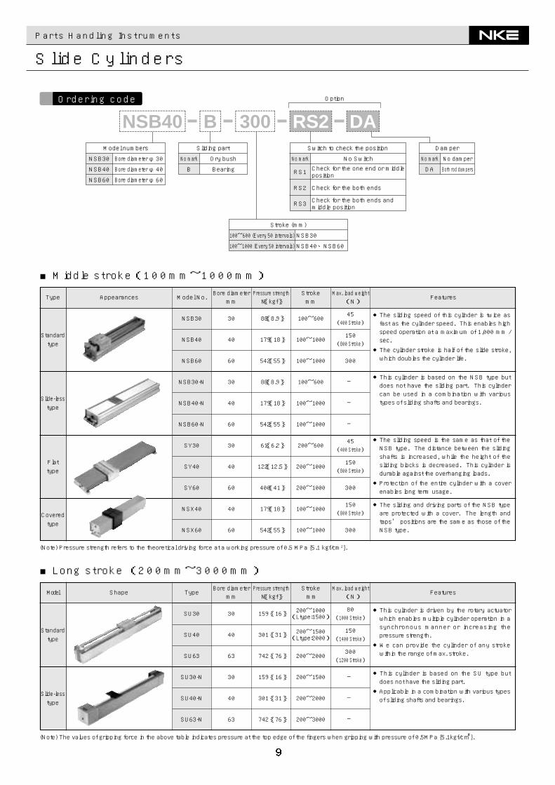
●The sliding speed of this cylinder is twice asfast as the cylinder speed. This enables highspeed operation at a maximum of 1,000 mm /sec.●The cylinder stroke is half of the slide stroke,which doubles the cylinder life.
●This cylinder is based on the NSB type butdoes not have the sliding part. This cylindercan be used in a combination with varioustypes of sliding shafts and bearings.
●The sliding speed is the same as that of theNSB type. The distance between the slidingshafts is increased, while the height of thesliding blocks is decreased. This cylinder isdurable against the overhanging loads.●Protection of the entire cylinder with a coverenables long term usage.
●The sliding and driving parts of the NSB typeare protected with a cover. The length andtaps’ positions are the same as those of theNSB type.
(Note) Pressure strength refers to the theoretical driving force at a working pressure of 0.5 MPa {5.1 kgf/cm2}.
Parts Handling Instruments
Slide Cylinders
■Middle stroke(100mm~1000mm)
Max. load weight(N)
●This cylinder is driven by the rotary actuatorwhich enables multiple cylinder operation in asynchronous manner or increasing thepressure strength.●We can provide the cylinder of any strokewithin the range of max. stroke.
●This cylinder is based on the SU type butdoes not have the sliding part.●Applicable in a combination with various typesof sliding shafts and bearings.
■Long stroke (200mm~3000mm)
(Note) The values of gripping force in the above table indicates pressure at the top edge of the fingers when gripping with pressure of 0.5MPa {5.1kgf/c㎡}.
Ordering code
Sliding part
No mark Dry bush
B Bearing
Switch to check the position
No SwitchCheck for the one end or middleposition
Check for the both ends
Check for the both ends andmiddle position
No mark
RS1
RS2
RS3
Damper
No damper
Both rod dampers
No mark
DA
Stroke (mm)
100~600 (Every 50 intervals)
100~1000 (Every 50 intervals)
NSB30
NSB40、NSB60
Option
B@@@@@@@@e?@@@@@@@@e?@@h?@@h?@@h?@@h?@@h?@@h?
@@@@@@@@e?@@@@@@@@?e@@@@@@@@e?@@@@@@@@?e@@@@@@@@e?@@@@@@@@?e@@@@@@@@e?@@@@@@@@e?@@@@@@@@?e@@@@@@@@e?@@@@@@@@?e@@@@@@@@e?@@@@@@@@?e@@@@@@@@e?
@@@@@@@@@@@@@@@@@@@@@@@@@@@@
@@@@@@@@@@@@@@@@
@@@@@@@@@@@@@@@@
@@@@@@@@@@@@@@@@
@@@@@@@@@@@@@@@@
@@@@@@@@@@@@@@@@
@@@@@@@@@@@@@@@@
@@@@@@@@@@@@@@@@
?@@?@@?@@?@@?@@?@@
?@@@@@@@@?@@@@@@@@
?@@@@@@@@?e@@@@@@@@e?@@@@@@@@?e@@@@@@@@e?@@@@@@@@?e@@@@@@@@e?@@@@@@@@?@@@@@@@@?e@@@@@@@@e?@@@@@@@@?e@@@@@@@@e?@@@@@@@@?e@@@@@@@@e?@@@@@@@@
@@g@@g@@g@@g@@g@@g@@@@@@@@@@@@@@@@
@@@@@@@@@@@@@@@@
@@@@@@@@@@@@@@@@
@@@@@@@@@@@@@@@@
@@@@@@@@@@@@@@@@
@@@@@@@@@@@@@@@@
@@@@@@@@@@@@@@@@
@@@@@@@@@@@@@@@@
300@@@@@@@@e?@@@@@@@@e?@@h?@@h?@@h?@@h?@@h?@@h?
@@@@@@@@e?@@@@@@@@?e@@@@@@@@e?@@@@@@@@?e@@@@@@@@e?@@@@@@@@?e@@@@@@@@e?@@@@@@@@?e@@@@@@@@e?@@@@@@@@?e@@@@@@@@e?@@@@@@@@?e@@@@@@@@e?@@@@@@@@?e@@@@@@@@e?@@@@@@@@?e@@@@@@@@e?@@@@@@@@?e@@@@@@@@e?@@@@@@@@?e@@@@@@@@e?@@@@@@@@?e@@@@@@@@e?@@@@@@@@?e@@@@@@@@e?@@@@@@@@?e@@@@@@@@e?@@@@@@@@?e
@@@@@@@@@@@@@@@@@@@@@@@@@@@@
@@@@@@@@@@@@@@@@
@@@@@@@@@@@@@@@@
@@@@@@@@@@@@@@@@
@@@@@@@@@@@@@@@@
@@@@@@@@@@@@@@@@
@@@@@@@@@@@@@@@@
@@@@@@@@@@@@@@@@
?@@?@@?@@?@@?@@?@@
?@@@@@@@@?@@@@@@@@
?@@@@@@@@?e@@@@@@@@e?@@@@@@@@?e@@@@@@@@e?@@@@@@@@?e@@@@@@@@e?@@@@@@@@?e@@@@@@@@e?@@@@@@@@?e@@@@@@@@e?@@@@@@@@?e@@@@@@@@e?@@@@@@@@?e@@@@@@@@?@@@@@@@@?e@@@@@@@@e?@@@@@@@@?e@@@@@@@@e?@@@@@@@@?e@@@@@@@@e?@@@@@@@@?e@@@@@@@@e?@@@@@@@@?e@@@@@@@@e?@@@@@@@@?e@@@@@@@@e?@@@@@@@@?e@@@@@@@@
@@g@@g@@g@@g@@g@@g@@@@@@@@@@@@@@@@
@@@@@@@@@@@@@@@@
@@@@@@@@@@@@@@@@
@@@@@@@@@@@@@@@@
@@@@@@@@@@@@@@@@
@@@@@@@@@@@@@@@@
@@@@@@@@@@@@@@@@
@@@@@@@@@@@@@@@@
NSB40@@@@@@@@e?@@@@@@@@e?@@h?@@h?@@h?@@h?@@h?@@h?
@@@@@@@@e?@@@@@@@@?e@@@@@@@@e?@@@@@@@@?e@@@@@@@@e?@@@@@@@@?e@@@@@@@@e?@@@@@@@@?e@@@@@@@@e?@@@@@@@@?e@@@@@@@@e?@@@@@@@@?e@@@@@@@@e?@@@@@@@@?e@@@@@@@@e?@@@@@@@@?e@@@@@@@@e?@@@@@@@@?e@@@@@@@@e?@@@@@@@@?e@@@@@@@@e?@@@@@@@@?e@@@@@@@@e?@@@@@@@@?e@@@@@@@@e?@@@@@@@@?e@@@@@@@@e?@@@@@@@@?e@@@@@@@@e?@@@@@@@@?e@@@@@@@@e?@@@@@@@@?e@@@@@@@@e?@@@@@@@@?e@@@@@@@@e?@@@@@@@@?e@@@@@@@@e?@@@@@@@@?e@@@@@@@@e?@@@@@@@@?e@@@@@@@@e?@@@@@@@@?e@@@@@@@@e?@@@@@@@@?e@@@@@@@@e?@@@@@@@@?e@@@@@@@@e?@@@@@@@@?e
@@@@@@@@@@@@@@@@@@@@@@@@@@@@
@@@@@@@@@@@@@@@@
@@@@@@@@@@@@@@@@
@@@@@@@@@@@@@@@@
@@@@@@@@@@@@@@@@
@@@@@@@@@@@@@@@@
@@@@@@@@@@@@@@@@
@@@@@@@@@@@@@@@@
?@@?@@?@@?@@?@@?@@
?@@@@@@@@?@@@@@@@@
?@@@@@@@@?e@@@@@@@@e?@@@@@@@@?e@@@@@@@@e?@@@@@@@@?e@@@@@@@@e?@@@@@@@@?e@@@@@@@@e?@@@@@@@@?e@@@@@@@@e?@@@@@@@@?e@@@@@@@@e?@@@@@@@@?e@@@@@@@@e?@@@@@@@@?e@@@@@@@@e?@@@@@@@@?e@@@@@@@@e?@@@@@@@@?e@@@@@@@@e?@@@@@@@@?e@@@@@@@@e?@@@@@@@@?e@@@@@@@@?@@@@@@@@?e@@@@@@@@e?@@@@@@@@?e@@@@@@@@e?@@@@@@@@?e@@@@@@@@e?@@@@@@@@?e@@@@@@@@e?@@@@@@@@?e@@@@@@@@e?@@@@@@@@?e@@@@@@@@e?@@@@@@@@?e@@@@@@@@e?@@@@@@@@?e@@@@@@@@e?@@@@@@@@?e@@@@@@@@e?@@@@@@@@?e@@@@@@@@e?@@@@@@@@?e@@@@@@@@e?@@@@@@@@?e@@@@@@@@
@@g@@g@@g@@g@@g@@g@@@@@@@@@@@@@@@@
@@@@@@@@@@@@@@@@
@@@@@@@@@@@@@@@@
@@@@@@@@@@@@@@@@
@@@@@@@@@@@@@@@@
@@@@@@@@@@@@@@@@
@@@@@@@@@@@@@@@@
@@@@@@@@@@@@@@@@
RS2@@@@@@@@e?@@@@@@@@e?@@h?@@h?@@h?@@h?@@h?@@h?
@@@@@@@@e?@@@@@@@@?e@@@@@@@@e?@@@@@@@@?e@@@@@@@@e?@@@@@@@@?e@@@@@@@@e?@@@@@@@@?e@@@@@@@@e?@@@@@@@@?e@@@@@@@@e?@@@@@@@@?e@@@@@@@@e?@@@@@@@@?e@@@@@@@@e?@@@@@@@@e?@@@@@@@@?e@@@@@@@@e?@@@@@@@@?e@@@@@@@@e?@@@@@@@@?e@@@@@@@@e?@@@@@@@@?e@@@@@@@@e?@@@@@@@@?e@@@@@@@@e?@@@@@@@@?e@@@@@@@@e?@@@@@@@@?e@@@@@@@@e?
@@@@@@@@@@@@@@@@@@@@@@@@@@@@
@@@@@@@@@@@@@@@@
@@@@@@@@@@@@@@@@
@@@@@@@@@@@@@@@@
@@@@@@@@@@@@@@@@
@@@@@@@@@@@@@@@@
@@@@@@@@@@@@@@@@
@@@@@@@@@@@@@@@@
?@@?@@?@@?@@?@@?@@
?@@@@@@@@?@@@@@@@@
?@@@@@@@@?e@@@@@@@@e?@@@@@@@@?e@@@@@@@@e?@@@@@@@@?e@@@@@@@@e?@@@@@@@@?e@@@@@@@@e?@@@@@@@@?e@@@@@@@@e?@@@@@@@@?e@@@@@@@@e?@@@@@@@@?e@@@@@@@@e?@@@@@@@@?@@@@@@@@?e@@@@@@@@e?@@@@@@@@?e@@@@@@@@e?@@@@@@@@?e@@@@@@@@e?@@@@@@@@?e@@@@@@@@e?@@@@@@@@?e@@@@@@@@e?@@@@@@@@?e@@@@@@@@e?@@@@@@@@?e@@@@@@@@e?@@@@@@@@
@@g@@g@@g@@g@@g@@g@@@@@@@@@@@@@@@@
@@@@@@@@@@@@@@@@
@@@@@@@@@@@@@@@@
@@@@@@@@@@@@@@@@
@@@@@@@@@@@@@@@@
@@@@@@@@@@@@@@@@
@@@@@@@@@@@@@@@@
@@@@@@@@@@@@@@@@
DA@@@@@@@@e?@@@@@@@@e?@@h?@@h?@@h?@@h?@@h?@@h?
@@@@@@@@e?@@@@@@@@?e@@@@@@@@e?@@@@@@@@?e@@@@@@@@e?@@@@@@@@?e@@@@@@@@e?@@@@@@@@?e@@@@@@@@e?@@@@@@@@?e@@@@@@@@e?@@@@@@@@e?@@@@@@@@?e@@@@@@@@e?@@@@@@@@?e@@@@@@@@e?@@@@@@@@?e@@@@@@@@e?@@@@@@@@?e@@@@@@@@e?@@@@@@@@?e@@@@@@@@e?
@@@@@@@@@@@@@@@@@@@@@@@@@@@@
@@@@@@@@@@@@@@@@
@@@@@@@@@@@@@@@@
@@@@@@@@@@@@@@@@
@@@@@@@@@@@@@@@@
@@@@@@@@@@@@@@@@
@@@@@@@@@@@@@@@@
@@@@@@@@@@@@@@@@
?@@?@@?@@?@@?@@?@@
?@@@@@@@@?@@@@@@@@
?@@@@@@@@?e@@@@@@@@e?@@@@@@@@?e@@@@@@@@e?@@@@@@@@?e@@@@@@@@e?@@@@@@@@?e@@@@@@@@e?@@@@@@@@?e@@@@@@@@e?@@@@@@@@?@@@@@@@@?e@@@@@@@@e?@@@@@@@@?e@@@@@@@@e?@@@@@@@@?e@@@@@@@@e?@@@@@@@@?e@@@@@@@@e?@@@@@@@@?e@@@@@@@@e?@@@@@@@@
@@g@@g@@g@@g@@g@@g@@@@@@@@@@@@@@@@
@@@@@@@@@@@@@@@@
@@@@@@@@@@@@@@@@
@@@@@@@@@@@@@@@@
@@@@@@@@@@@@@@@@
@@@@@@@@@@@@@@@@
@@@@@@@@@@@@@@@@
@@@@@@@@@@@@@@@@
Model numbers
NSB30
NSB40
NSB60
Bore diameter φ30
Bore diameter φ40
Bore diameter φ60
94
184
96
186
95
191
286
94
186
90
180
90
180
90
180
90
180
0.2~5.0
0.3~7.0
0.5~2.5
0.7~3.0
0.5~2.5
0.7~3.0
0.7~3.5
1.0~4.0
1.5~4.0
2.0~5.0
2.5{26} 0.15{1.5}
5.4{55} 0.8{8.2}
13{132} 1.0{10.2}
RM405.7{58}(Note)
0.26{2.7}0.5~1.5/180°
RM20 1.0{10.2} 0.07{0.7}
RM15
RT20W
NRU30
NRU40
RU60
RU80
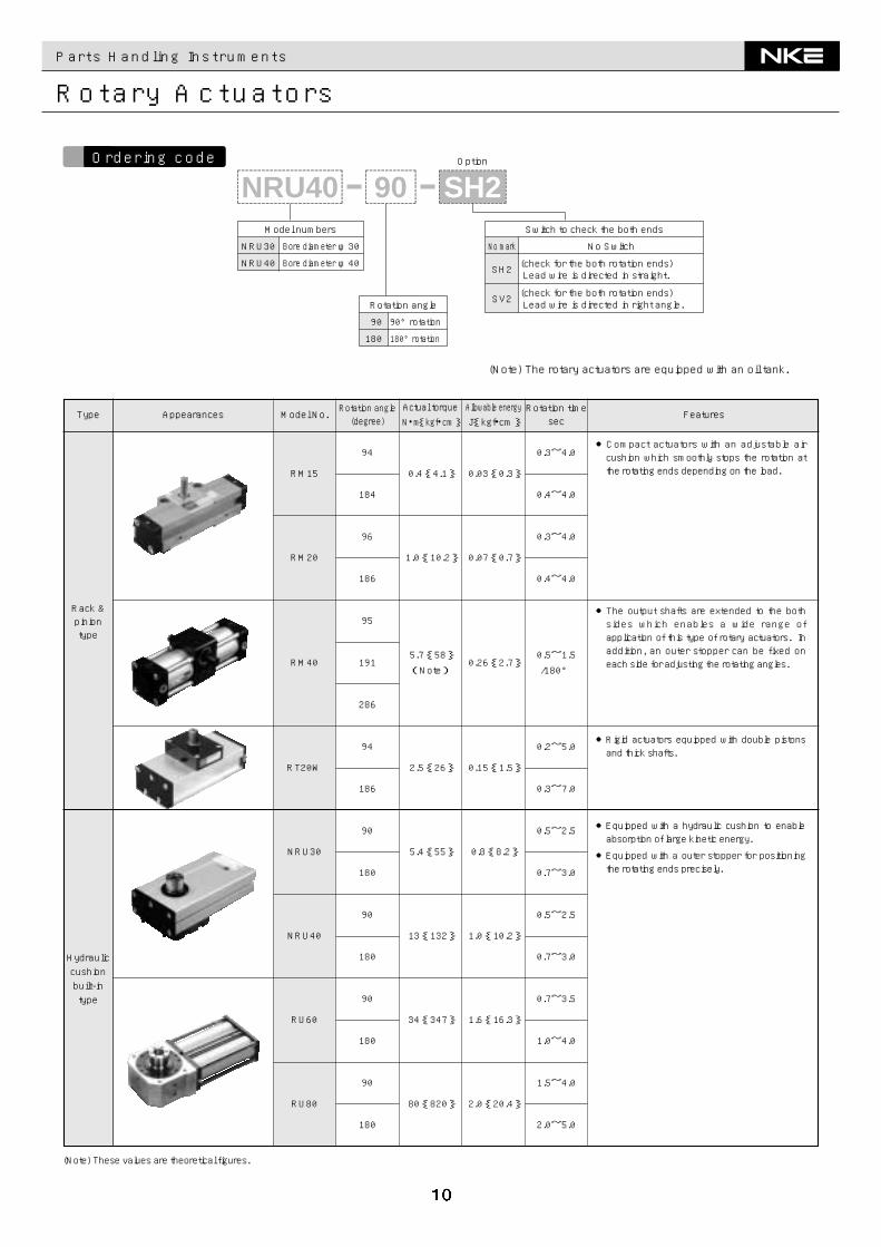
Type Appearances FeaturesModel No.Rotation angle(degree)
Actual torqueN・m{kgf・cm}
Allowable energyJ{kgf・cm}
Rotation timesec
Rack &piniontype
Hydrauliccushionbuilt-intype
0.4{4.1} 0.03{0.3}
34{347} 1.6{16.3}
80{820} 2.0{20.4}
0.3~4.0
0.4~4.0
0.3~4.0
0.4~4.0
●Compact actuators with an adjustable aircushion which smoothly stops the rotation atthe rotating ends depending on the load.
●The output shafts are extended to the bothsides which enables a wide range ofapplication of this type of rotary actuators. Inaddition, an outer stopper can be fixed oneach side for adjusting the rotating angles.
●Rigid actuators equipped with double pistonsand thick shafts.
●Equipped with a hydraulic cushion to enableabsorption of large kinetic energy.
●Equipped with a outer stopper for positioningthe rotating ends precisely.
(Note) These values are theoretical figures.
Parts Handling Instruments
Rotary Actuators
Option
90@@@@@@@@e?@@@@@@@@e?@@h?@@h?@@h?@@h?@@h?@@h?
@@@@@@@@e?@@@@@@@@?e@@@@@@@@e?@@@@@@@@?e@@@@@@@@e?@@@@@@@@?e@@@@@@@@e?@@@@@@@@?e@@@@@@@@e?@@@@@@@@?e@@@@@@@@e?@@@@@@@@e?@@@@@@@@?e@@@@@@@@e?@@@@@@@@?e@@@@@@@@e?@@@@@@@@?e@@@@@@@@e?@@@@@@@@?e@@@@@@@@e?@@@@@@@@?e@@@@@@@@e?
@@@@@@@@@@@@@@@@@@@@@@@@@@@@
@@@@@@@@@@@@@@@@
@@@@@@@@@@@@@@@@
@@@@@@@@@@@@@@@@
@@@@@@@@@@@@@@@@
@@@@@@@@@@@@@@@@
@@@@@@@@@@@@@@@@
@@@@@@@@@@@@@@@@
?@@?@@?@@?@@?@@?@@
?@@@@@@@@?@@@@@@@@
?@@@@@@@@?e@@@@@@@@e?@@@@@@@@?e@@@@@@@@e?@@@@@@@@?e@@@@@@@@e?@@@@@@@@?e@@@@@@@@e?@@@@@@@@?e@@@@@@@@e?@@@@@@@@?@@@@@@@@?e@@@@@@@@e?@@@@@@@@?e@@@@@@@@e?@@@@@@@@?e@@@@@@@@e?@@@@@@@@?e@@@@@@@@e?@@@@@@@@?e@@@@@@@@e?@@@@@@@@
@@g@@g@@g@@g@@g@@g@@@@@@@@@@@@@@@@
@@@@@@@@@@@@@@@@
@@@@@@@@@@@@@@@@
@@@@@@@@@@@@@@@@
@@@@@@@@@@@@@@@@
@@@@@@@@@@@@@@@@
@@@@@@@@@@@@@@@@
@@@@@@@@@@@@@@@@
NRU40@@@@@@@@e?@@@@@@@@e?@@h?@@h?@@h?@@h?@@h?@@h?
@@@@@@@@e?@@@@@@@@?e@@@@@@@@e?@@@@@@@@?e@@@@@@@@e?@@@@@@@@?e@@@@@@@@e?@@@@@@@@?e@@@@@@@@e?@@@@@@@@?e@@@@@@@@e?@@@@@@@@?e@@@@@@@@e?@@@@@@@@?e@@@@@@@@e?@@@@@@@@?e@@@@@@@@e?@@@@@@@@?e@@@@@@@@e?@@@@@@@@?e@@@@@@@@e?@@@@@@@@?e@@@@@@@@e?@@@@@@@@?e@@@@@@@@e?@@@@@@@@?e@@@@@@@@e?@@@@@@@@?e@@@@@@@@e?@@@@@@@@?e@@@@@@@@e?@@@@@@@@?e@@@@@@@@e?@@@@@@@@?e@@@@@@@@e?@@@@@@@@?e@@@@@@@@e?@@@@@@@@?e@@@@@@@@e?@@@@@@@@?e@@@@@@@@e?@@@@@@@@?e@@@@@@@@e?@@@@@@@@?e@@@@@@@@e?@@@@@@@@?e@@@@@@@@e?@@@@@@@@?e
@@@@@@@@@@@@@@@@@@@@@@@@@@@@
@@@@@@@@@@@@@@@@
@@@@@@@@@@@@@@@@
@@@@@@@@@@@@@@@@
@@@@@@@@@@@@@@@@
@@@@@@@@@@@@@@@@
@@@@@@@@@@@@@@@@
@@@@@@@@@@@@@@@@
?@@?@@?@@?@@?@@?@@
?@@@@@@@@?@@@@@@@@
?@@@@@@@@?e@@@@@@@@e?@@@@@@@@?e@@@@@@@@e?@@@@@@@@?e@@@@@@@@e?@@@@@@@@?e@@@@@@@@e?@@@@@@@@?e@@@@@@@@e?@@@@@@@@?e@@@@@@@@e?@@@@@@@@?e@@@@@@@@e?@@@@@@@@?e@@@@@@@@e?@@@@@@@@?e@@@@@@@@e?@@@@@@@@?e@@@@@@@@e?@@@@@@@@?e@@@@@@@@e?@@@@@@@@?e@@@@@@@@?@@@@@@@@?e@@@@@@@@e?@@@@@@@@?e@@@@@@@@e?@@@@@@@@?e@@@@@@@@e?@@@@@@@@?e@@@@@@@@e?@@@@@@@@?e@@@@@@@@e?@@@@@@@@?e@@@@@@@@e?@@@@@@@@?e@@@@@@@@e?@@@@@@@@?e@@@@@@@@e?@@@@@@@@?e@@@@@@@@e?@@@@@@@@?e@@@@@@@@e?@@@@@@@@?e@@@@@@@@e?@@@@@@@@?e@@@@@@@@
@@g@@g@@g@@g@@g@@g@@@@@@@@@@@@@@@@
@@@@@@@@@@@@@@@@
@@@@@@@@@@@@@@@@
@@@@@@@@@@@@@@@@
@@@@@@@@@@@@@@@@
@@@@@@@@@@@@@@@@
@@@@@@@@@@@@@@@@
@@@@@@@@@@@@@@@@
SH2@@@@@@@@e?@@@@@@@@e?@@h?@@h?@@h?@@h?@@h?@@h?
@@@@@@@@e?@@@@@@@@?e@@@@@@@@e?@@@@@@@@?e@@@@@@@@e?@@@@@@@@?e@@@@@@@@e?@@@@@@@@?e@@@@@@@@e?@@@@@@@@?e@@@@@@@@e?@@@@@@@@?e@@@@@@@@e?@@@@@@@@?e@@@@@@@@e?@@@@@@@@e?@@@@@@@@?e@@@@@@@@e?@@@@@@@@?e@@@@@@@@e?@@@@@@@@?e@@@@@@@@e?@@@@@@@@?e@@@@@@@@e?@@@@@@@@?e@@@@@@@@e?@@@@@@@@?e@@@@@@@@e?@@@@@@@@?e@@@@@@@@e?
@@@@@@@@@@@@@@@@@@@@@@@@@@@@
@@@@@@@@@@@@@@@@
@@@@@@@@@@@@@@@@
@@@@@@@@@@@@@@@@
@@@@@@@@@@@@@@@@
@@@@@@@@@@@@@@@@
@@@@@@@@@@@@@@@@
@@@@@@@@@@@@@@@@
?@@?@@?@@?@@?@@?@@
?@@@@@@@@?@@@@@@@@
?@@@@@@@@?e@@@@@@@@e?@@@@@@@@?e@@@@@@@@e?@@@@@@@@?e@@@@@@@@e?@@@@@@@@?e@@@@@@@@e?@@@@@@@@?e@@@@@@@@e?@@@@@@@@?e@@@@@@@@e?@@@@@@@@?e@@@@@@@@e?@@@@@@@@?@@@@@@@@?e@@@@@@@@e?@@@@@@@@?e@@@@@@@@e?@@@@@@@@?e@@@@@@@@e?@@@@@@@@?e@@@@@@@@e?@@@@@@@@?e@@@@@@@@e?@@@@@@@@?e@@@@@@@@e?@@@@@@@@?e@@@@@@@@e?@@@@@@@@
@@g@@g@@g@@g@@g@@g@@@@@@@@@@@@@@@@
@@@@@@@@@@@@@@@@
@@@@@@@@@@@@@@@@
@@@@@@@@@@@@@@@@
@@@@@@@@@@@@@@@@
@@@@@@@@@@@@@@@@
@@@@@@@@@@@@@@@@
@@@@@@@@@@@@@@@@
Model numbers
NRU30
NRU40
Bore diameter φ30
Bore diameter φ40
Rotation angle
90 90°rotation
180 180°rotation
Switch to check the both ends
No Switch
(check for the both rotation ends)Lead wire is directed in straight.
No mark
SH2
SV2 (check for the both rotation ends)Lead wire is directed in right angle.
(Note) The rotary actuators are equipped with an oil tank.
Ordering code
Conveyors ■Micro Conveyor CS20Conveyor Instruments
12�
50
132~500�
2.0�
2.9
501~750�
2.2�
3.4
751~1000�
2.5�
3.9
Distance between pulleys (mm)
(kg)
Belt width�(mm)
The above table indicates the maximum value for each distance between pulleys.
Temperature
Static electricity
Friction efficiency
Sanitary
Material
Color
Thickness
Manufacturer's model number
Oil
Polyurethane impregnation
Green
○�
-30~80℃�
○�
○�
0.5~0.9
0.7mm
Mitsuboshi belt co.,itd NS41UN0/2G
Conveying capacity(N)�
Belt speed (m/sec)
5
10
15
20
25
30
35
40
45
50
0
0
0.01
0.02
0.03
0.04
0.05
0.06
0.07
0.08
0.09 0.1
0.13
0.14
0.15
0.16
0.18 0.2
6W(Belt width 50)�
6W(Belt width 12)�750g
125g
The graph shown above indicates total the total conveying capacity without accumulation of the work on the conveyor.�In case of accumulation of work, the capacity is generally assumed to be decreased by more than half of the above values.�(Note) 1N≒0.102 kgf
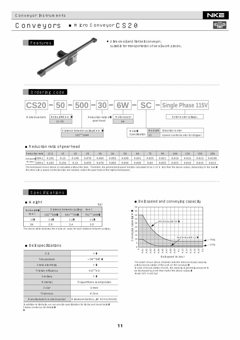
In addition to flat belts, we can provide specifications for timing and round belts.�Please contact us for details.��
●Ultra-small and flat belt conveyor,suitable for transportation of small work pieces.
Motor�Specification
No mark
SC
Induction motor
Speed control motor (Unit type)
Belt width(mm)�
12、50
Motor power
6W
Enter motor voltage.
Distance between pulleys(mm)�
132~1000
Model numbers Reduction ratio of�gear head
CS20 3050050 6W SC Single Phase 115V
Belt speed�(m/sec)
The belt speed shown above is calculated without the load. Therefore, the general belt speed shall be calculated to be 2-15 % less than the above values, depending on the load.�If motors with a speed control function are needed, select the gear head at the highest belt speed.
Reduction ratio
50Hz
60Hz
180
0.0108
0.013
150
0.013
0.015
120
0.016
0.018
100
0.018
0.023
90
0.021
0.025
75
0.025
0.03
60
0.031
0.038
50
0.038
0.046
36
0.053
0.065
30
0.065
0.078
25
0.078
0.093
18
0.108
0.13
15
0.13
0.156
12.5
0.156
0.183
■Weight
■Reduction ratio of gear head
■Belt speed and conveying capacity
■Belt specifications
Ordering code
Features
Specifications
Conveyor Instruments
Conveyors ■Belt Conveyor CSJ30-A
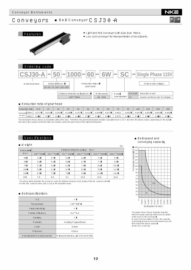
●Light and thin conveyor with aluminum frame.●Low cost conveyor for transportation of small parts.
Reduction ratio of�gear head
Belt width(mm)�
30、50、75、100、150、200
Distance between pulleys(mm)�
180~3000
Model numbers
CSJ30-A 60100050 6W SC
Motor power
6W、25W
Enter motor voltage.
Single Phase 115V
Motor�Specification
No mark
SC
Induction motor
Speed control motor (Unit type)
0
0.033
0.067
0.100
0.133
0.167
0.200
0.233
0.267
0.300
0.333
Conveying capacity(N)�
Belt speed (m/sec)
6W
25W
10
20
30
40
50
60
70
80
90
100
110
120
130
140
150
160
The graph shown above indicates total the total conveying capacity without accumulation of the work on the conveyor.�In case of accumulation of work, the capacity is generally assumed to be decreased by more than half of the above values.�(Note) 1N≒0.102 kgf
30�
50�
75�
100�
150�
200
180~500�
4.3�
4.6�
5.1�
5.5�
6.5�
7.5
501~750�
4.7�
5.1�
5.6�
6.1�
7.3�
8.3
751~1000�
5.2�
5.6�
6.2�
6.7�
7.8�
9.1
1001~1500�
6.2�
6.7�
7.4�
8.1�
9.6�
10.9
1501~2000�
7.1�
7.7�
8.6�
9.2�
11.0�
12.6
2001~3000�
9.2�
9.9�
10.9�
11.9�
14.1�
16.0
Distance between pulleys (mm)
(kg)
Belt width�(mm)
The above table indicates the maximum value for distance between each pulley of the 6W output motors.�For the 25W output motors, add 1.3 kg to the indicated value.
Holding Polyurethane
Green
○�
-30~80℃�
○�
○�
0.2~0.3
0.5mm
Mitsuboshi belt co.,itd NS41UM0/0G
Belt speed�(m/sec)
The belt speed shown above is calculated without the load. Therefore, the general belt speed shall be calculated to be 2-15 % less than the above values, depending on the load.�If motors with a speed control function are needed, select the gear head at the highest belt speed.
Reduction ratio
50Hz
60Hz
180
0.026�
�0.031
150
0.031�
�0.038
120
0.039�
�0.047
100
0.047�
�0.057
90
0.052�
�0.063
75
0.063
0.075
60
0.079�
�0.094
50
0.094�
�0.113
36
0.131�
�0.157
30
0.157�
�0.188
25
0.188�
�0.226
18
0.262�
�0.314
15
0.314�
�0.377
12.5
0.377�
�0.452
Temperature
Static electricity
Friction efficiency
Sanitary
Material
Color
Thickness
Manufacturer's model number
Oil
■Reduction ratio of gear head
■Weight
■Belt speed andconveying capacity
■Belt specifications
Ordering code
Features
Specifications
Conveyor Instruments
Conveyors ■Belt Conveyor CSJ30 Series
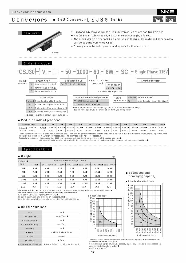
●Light and thin conveyors with aluminum frames, which are easily maintained.●Available with roller-knife edge which ensures conveying of parts.●The middle driving motor enables alternative positioning of the motor and its orientationcan be selected from three types.●Conveyors can be set in parallel and operated with one motor.
CSJ30-V
*The minimum distance between pulleys are: 142 mm for V type driving motor,� 122 mm for H type driving motor and 61 mm for T type driving motor.
※Roller knife edge : 25W
Distance between pulleys(mm)�
~4000(Round pulley)�
~2000(Roller knife edge)
Reduction ratio of�gear head
Belt width(mm)�
30, 50, 75,100, 150, 200 Motor power
6W、15W、25W
Model�numbers
CSJ30 60100050V 20 6W SCDriving motor
V
H
T
Motor mounted in vertical
Motor mounted in parallel
Motor mounted directly
*In case of roller-knife edge, motor output is 25W.
Pulley shape
No mark
RK
RF
Round pulley at both ends
Roller knife edge at both ends
Roller knife edge at downstream end
RB Roller knife edge at upstream end
�50Hz�60Hz
12.5�0.313�―�
15�0.262�0.313
18�0.218�0.262
25�0.157�0.188
30�0.132�0.157
36�0.108�0.132
50�0.078�0.095
60�0.065�0.078
75�0.052�0.063
90�0.043�0.052
100�0.040�0.047
120�0.033�0.040
150�0.027�0.032
180�0.022�0.027
Reduction ratio
Belt speed�(m/sec)
The belt speed shown above is calculated without the load. Therefore, the general belt speed shall be calculated to be 2-15 % less than the above values, depending on the load.�If motors with a speed control function are needed, select the gear head at the highest belt speed.�(Precautions before use) Gear is used for CSJ30 conveyors, and V/H type driving motors. In case of high speed operation,� driving motor noise becomes slightly louder, but it does not effect on the quality. We deliver conveyors which meet our standards.��
Motor�Specification
No mark
SC
Induction motor
Speed control motor (Unit type)
Enter motor voltage.
Single Phase 115V
30�
50�
75�
100�
150�
200
~500�
4.4�
5.9�
6.2�
6.5�
7.5�
8.2
501~750�
4.6�
6.2�
6.5�
7.1�
8.2�
9.1
751~1000�
5.1�
6.8�
7.2�
7.7�
9.0�
10.0
1001~1500�
5.8�
7.6�
8.2�
8.8�
10.5�
11.7
1501~2000�
6.5�
8.4�
9.2�
9.9�
12.0�
13.5
2001~3000�
8.3�
10.4�
11.4�
12.3�
14.8�
16.8
3001~4000�
10.0�
12.3�
13.5�
14.6�
17.6�
20.1
Distance between pulleys (mm)
(kg)
Belt width�(mm)
The above table indicates the maximum weight of V type with 6W output motors and round pulleys at both ends.�The value needs to be modified based on the following specifications:�(1) H type: Plus 0.3 kg, T type: Subtract 0.7 kg.�(2) 15W motor: Plus 0.6 kg, 25W motor: Subtract 1.2 kg�(3) Knife-edge type: Subtract 0.4-1 kg per on edge (Belt width: 30-200 mm)
The graph shown above indicates total the total conveying capacity without accumula-tion of the work on the conveyor.�In case of accumulation of work, the capacity is generally assumed to be decreased by more than half of the above values.�(Note) 1N≒0.102 kgf
00.033
0.067
0.100
0.133
0.167
0.200
0.233
0.267
0.300
0.333
Conveying capacity(N)�
Belt speed (m/sec)
6W
15W
25W
102030405060708090100110120130140150160
■Round pulley at both ends
Conveying capacity(N)�
00.033
0.067
0.100
0.133
0.167
0.200
0.233
0.267
0.3000.333
Belt speed (m/sec)
25W102030405060708090100110
■Roller knife edge
Holding Polyurethane
Green
○�
-30~80℃�
○�
○�
0.2~0.3
0.5mm
Mitsuboshi belt co.,itd NS41UN0/2G
Temperature
Static electricity
Friction efficiency
Sanitary
Material
Color
Thickness
Manufacturer's model number
Oil
■Reduction ratio of gear head
■Weight
■Belt speed andconveying capacity
■Belt specifications
Ordering code
Features
Specifications
Conveyor Instruments
Conveyors ■Belt Conveyor CSSK50 Series
※200V : 6W,25W,40W
Distance between pulleys(mm)�(Please refer to the related� table shown below.)
Reduction ratio of gear head
Belt width(mm)�
CSSK50
CSSK50M
40、50、75、100、150、200、300、400、500
40、50、75、100、150、200、300
Motor power
6W、15W�25W、40W
CSSK50 60100050 6W SCModel numbers
CSSK50
CSSK50M
Head driving
Middle driving
The belt speed shown above is calculated without the load. Therefore, the general belt speed shall be calculated to be 2-15 % less than the above values, depending on the load.�If motors with a speed control function are needed, select the gear head at the highest belt speed.
�
50Hz�
60Hz
12.5�
0.313�
―�
Reduction ratio 15�
0.262�
0.313
18�
0.218�
0.262
25�
0.157�
0.188
30�
0.132�
0.157
36�
0.108�
0.132
50�
0.078�
0.095
60�
0.065�
0.078
75�
0.052�
0.063
90�
0.043�
0.052
100�
0.040�
0.047
120�
0.033�
0.040
150�
0.027�
0.032
180�
0.022�
0.027Belt speed�(m/sec)
Motor�Specification
No mark
SC
Induction motor
Speed control motor (Unit type)
Enter motor voltage.
Single Phase 115V
Conveying capacity(N)�
Belt speed (m/sec)
6W
15W
25W
40W
10
20
30
40
50
60
70
80
90
100
110
120
130
140
150
160
0.0330
0.067
0.100
0.133
0.167
0.200
0.233
0.267
0.300
0.333
Type
CSSK50
Belt width (mm)
40 , 50 , 75�100 , 150 , 200�300 , 400 , 500
40 , 50 , 75�100 , 150�200 , 300
Distance between pulleys(mm)
192~4000 (6W)�197~4000 (15W)�219~4000(25W)�223~4000(40W)�308~4000(6W)�320~4000 (15W)�335~4000 (25W)�341~4000(40W)�
CSSK50M
The graph shown above indicates total the total conveying capacity without accumulation of the work on the conveyor.�In case of accumulation of work, the capacity is generally assumed to be decreased by more than half of the above values.�(Note) 1N≒0.102 kgf
40�50�75�100�150�200�300
6.2�6.4�7.1�7.7�9.3�11.1�15.1
7.4�7.7�8.4�9�10.6�12.4�16.2
8.6�8.9�9.6�10.2�11.8�13.6�17.3
10.5�10.8�11.5�12.1�14.3�16.6�20.3
12.1�12.5�13.9�14.6�16.8�19.1�23.3
16.1�16.5�17.9�19.1�21.8�24.6�29.3
20.1�20.5�21.9�23.6�26.8�30.1�35.2
40�50�75�100�150�200�300�400�500
180~500�4.6�4.7�5.1�5.5�6.6�7.8�―�―�―�
501~750�
5.8�6�6.4�6.8�7.9�9.1�―�―�―�
751~1000�7�7.2�7.6�8�9.1�10.3�13�15.3�18
1001~1500�8.9�9.1�9.5�9.9�11.6�13.3�16�18.8�21.5
1501~2000�10.5�10.8�11.9�12.4�14.1�15.8�19�22.3�25
2001~3000�14.5�14.8�15.9�16.9�19.1�21.3�25�29.3�32
3001~4000�18.5�18.8�19.9�21.4�24.1�26.8�30.9�36.2�38.9
Distance between pulleys (mm)
(kg)
Belt width�(mm)
Type
The above table shows the maximum value of each distance between pulleys of 6W motors.�For 15W motor, add 0.5 kg. For 25W motor, add 1.0 kg. For 40W motor, add 3.5 kg.
CSSK50
CSSK50M
○�
-30~80℃�
○�
○�
0.2~0.3
0.5mm
Mitsuboshi belt co.,itd �NS41UM0/0G
(Note 1) This table shows distance between pulleys depending on motor output. In case of wide belt, the minimum distance between pulleys becomes more than double the length of the belt’s width.�
(Note 2) If you need more than 4000 mm between pulleys, please contact us for details.
Temperature
Static electricity
Friction efficiency
Sanitary
Oil Material
Color
Thickness
Manufacturer's model number
Holding Polyurethane
Green
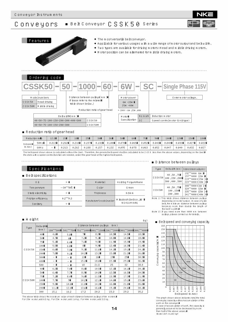
●The most versatile belt conveyor.●Applicable for various usages with a wide range of motor output and belt width.●Two types are available for driving motors: Head and middle driving motors.●Motor position can be alternated for middle driving motors.
■Reduction ratio of gear head
■Weight
■Distance between pulleys
■Belt speed and conveying capacity
■Belt specifications
Ordering code
Features
Specifications
Conveyor Instruments
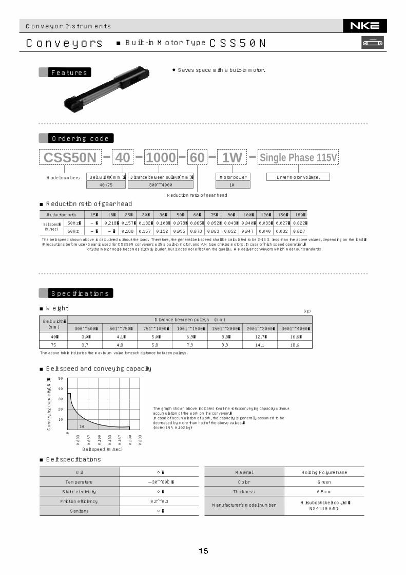
Conveyors ■Built-in Motor Type CSS50N
Belt width(mm)�
40、75
Motor power
1W
Distance between pulleys(mm)�
300~4000Model numbers
Reduction ratio of gear head
CSS50N 60100040 1WEnter motor voltage.
Single Phase 115V
0
0.033
0.067
0.100
0.133
0.167
0.200
0.233
Conveying capacity(N)�
Belt speed (m/sec)
10
20
30
40
50
1W
The graph shown above indicates total the total conveying capacity without accumulation of the work on the conveyor.�In case of accumulation of work, the capacity is generally assumed to be decreased by more than half of the above values.�(Note) 1N≒0.102 kgf
40�
75
300~500�
3.0�
3.7
501~750�
4.1�
4.8
751~1000�
5.0�
5.8
1001~1500�
6.9�
7.9
1501~2000�
8.8�
9.9
2001~3000�
12.7�
14.1
3001~4000�
16.6�
18.6
Distance between pulleys (mm)
(kg)
Belt width�(mm)
The above table indicates the maximum value for each distance between pulleys.
○�
-30~80℃�
○�
○�
0.2~0.3
Holding Polyurethane
Green
0.5mm
Mitsuboshi belt co.,itd �NS41UM0/0G
Temperature
Static electricity
Friction efficiency
Sanitary
Oil Material
Color
Thickness
Manufacturer's model number
The belt speed shown above is calculated without the load. Therefore, the general belt speed shall be calculated to be 2-15 % less than the above values, depending on the load.�(Precautions before use) Gear is used for CSS50N conveyors with a built-in motor, and V/H type driving motors. In case of high speed operation,� driving motor noise becomes slightly louder, but it does not effect on the quality. We deliver conveyors which meet our standards.
Reduction ratio 15�
―�
―�
18�
0.218�
―�
25�
0.157�
0.188
30�
0.132�
0.157
36�
0.108�
0.132
50�
0.078�
0.095
60�
0.065�
0.078
75�
0.052�
0.063
90�
0.043�
0.052
100�
0.040�
0.047
120�
0.033�
0.040
150�
0.027�
0.032
180�
0.022�
0.027
50Hz�
60HzBelt speed�(m/sec)
●Saves space with a built-in motor.
■Reduction ratio of gear head
■Weight
■Belt specifications
■Belt speed and conveying capacity
Ordering code
Features
Specifications
Conveyor Instruments
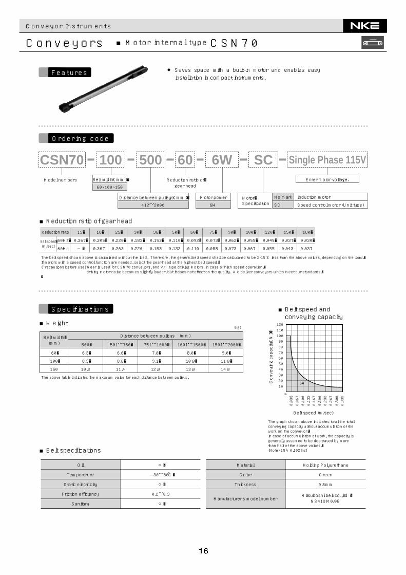
Conveyors ■Motor internal type CSN70
Belt width(mm)�
60、100、150
Motor power
6W
Model numbers Reduction ratio of�gear head
CSN70 60500100 6W SC
Distance between pulleys(mm)�
412~2000Motor�Specification
No mark
SC
Induction motor
Speed control motor (Unit type)
Enter motor voltage.
Single Phase 115V
60�
100�
150
500�
6.3�
8.3�
10.8
501~750�
6.6�
8.6�
11.4
751~1000�
7.0�
9.1�
12.0
1001~1500�
8.0�
10.0�
13.0
1501~2000�
9.0�
11.0�
14.0
Distance between pulleys (mm)
(kg)
Belt width�(mm)
The above table indicates the maximum value for each distance between pulleys.
00.033
0.067
0.100
0.133
0.167
0.200
0.233
0.267
0.300
0.333
Conveying capacity(N)�
Belt speed (m/sec)
6W102030405060708090100110120
The graph shown above indicates total the total conveying capacity without accumulation of the work on the conveyor.�In case of accumulation of work, the capacity is generally assumed to be decreased by more than half of the above values.�(Note) 1N≒0.102 kgf
○�
-30~80℃�
○�
○�
0.2~0.3
Holding Polyurethane
Green
0.5mm
Mitsuboshi belt co.,itd �NS41UM0/0G
Temperature
Static electricity
Friction efficiency
Sanitary
Oil Material
Color
Thickness
Manufacturer's model number
The belt speed shown above is calculated without the load. Therefore, the general belt speed shall be calculated to be 2-15 % less than the above values, depending on the load.�If motors with a speed control function are needed, select the gear head at the highest belt speed.�(Precautions before use) Gear is used for CSN70 conveyors, and V/H type driving motors. In case of high speed operation,� driving motor noise becomes slightly louder, but it does not effect on the quality. We deliver conveyors which meet our standards.��
Reduction ratio 15�
0.367�
―�
18�
0.305�
0.367
25�
0.220�
0.263
30�
0.183�
0.220
36�
0.153�
0.183
50�
0.110�
0.132
60�
0.092�
0.110
75�
0.073�
0.088
90�
0.062�
0.073
100�
0.055�
0.067
120�
0.045�
0.055
150�
0.037�
0.043
180�
0.030�
0.037
50Hz�
60Hz
Belt speed�(m/sec)
● Saves space with a built-in motor and enables easyinstallation in compact instruments.
■Reduction ratio of gear head
■Weight
■Belt specifications
■Belt speed andconveying capacity
Ordering code
Features
Specifications
Conveyor Instruments
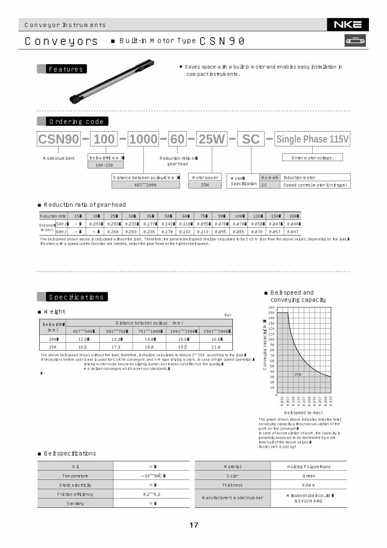
Conveyors ■Built-in Motor Type CSN90
Motor power
25W
Model numbers Reduction ratio of�gear head
CSN90 60100 25W SC1000
Motor�Specification
No mark
SC
Induction motor
Speed control motor (Unit type)
Distance between pulleys(mm)�
487~2000
Belt width(mm)�
100、150
Enter motor voltage.
Single Phase 115V
100�
150
487~500�
12.5�
16.5
501~750�
13.3�
17.3
751~1000�
14.0�
18.0
1001~1500�
15.5�
19.5
1501~2000�
16.5�
21.0
Distance between pulleys (mm)
(kg)
Belt width�(mm)
The above belt speed shows without the load, therefore, it shall be calculated to reduce 2~15% according to the load.�(Precautions before use) Gear is used for CSN90 conveyors, and V/H type driving motors. In case of high speed operation,� driving motor noise becomes slightly louder, but it does not effect on the quality.� We deliver conveyors which meet our standards.��
00.033
0.067
0.100
0.133
0.167
0.200
0.233
0.267
0.300
0.333
Conveying capacity(N)�
Belt speed (m/sec)
25W
102030405060708090100110120130140150160
The graph shown above indicates total the total conveying capacity without accumulation of the work on the conveyor.�In case of accumulation of work, the capacity is generally assumed to be decreased by more than half of the above values.�(Note) 1N≒0.102 kgf
○�
-30~80℃�
○�
○�
0.2~0.3
Holding Polyurethane
Green
0.5mm
Mitsuboshi belt co.,itd �NS41UM0/0G
Material
Color
Thickness
Manufacturer's model number
Temperature
Static electricity
Friction efficiency
Sanitary
Oil
The belt speed shown above is calculated without the load. Therefore, the general belt speed shall be calculated to be 2-15 % less than the above values, depending on the load.�If motors with a speed control function are needed, select the gear head at the highest belt speed.
Reduction ratio 15�
―�
―�
18�
0.393�
―�
25�
0.283�
0.340
30�
0.235�
0.283
36�
0.197�
0.235
50�
0.142�
0.170
60�
0.118�
0.142
75�
0.095�
0.113
90�
0.078�
0.095
100�
0.070�
0.085
120�
0.058�
0.070
150�
0.047�
0.057
180�
0.040�
0.047
50Hz�
60HzBelt speed�(m/sec)
●Saves space with a built-in motor and enables easy installation incompact instruments.
■Reduction ratio of gear head
■Weight
■Belt specifications
■Belt speed andconveying capacity
Ordering code
Features
Specifications
Conveyor Instruments
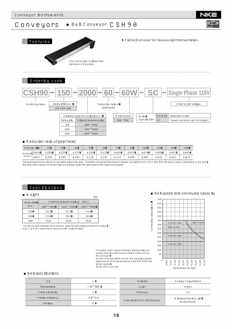
Conveyors ■Belt Conveyor CSH90
Belt width(mm)�
150、200、300
Motor power
60W、90W
Model numbers Reduction ratio of�gear head
CSH90 60150 60W SC2000
Distance between pulleys(mm)�
Belt width Distance between pulley
150 300~3000
200 400~3000
300 600~3000
Motor�Specification
No mark
SC
Induction motor
Speed control motor (Unit type)
Enter motor voltage.
Single Phase 115V
The graph shown above indicates total the total con-veying capacity without accumulation of the work on the conveyor.�In case of accumulation of work, the capacity is gener-ally assumed to be decreased by more than half of the above values.�(Note) 1N≒0.102 kgf
Conveying capacity(N)�
Belt speed (m/sec)
0
0.033
0.067
0.100
0.133
0.167
0.200
0.233
0.267
0.300
0.333
60W Motor
90W MotorCSH90ー300
CSH90ー200
CSH90ー150
100
50
150
200
250
300
350
400
450
500
550
600
650
700
150�
200�
300
300~1000�
22.5�
24.8�
29.4
1001~2000�
31.7�
35.2�
42.0
2001~3000�
41.4�
46.0�
55.0
Distance between pulleys (mm)
(kg)
Belt width�(mm)
The above table indicates the maximum value for each distance between pulleys.�Add 1 kg to the value shown above for 90W output motors.
○�
-30~80℃�
○�
○�
0.5~0.9
1.3
Mitsuboshi belt co.,itd �NS82UN0/2G
Temperature
Static electricity
Friction efficiency
Sanitary
Oil Material
Color
Thickness
Manufacturer's model number
Holding Polyurethane
Green
The belt speed shown above is calculated without the load. Therefore, the general belt speed shall be calculated to be 2-15 % less than the above values, depending on the load.�If motors with a speed control function are needed, select the gear head at the highest belt speed.
�
50Hz�
60Hz
Reduction ratio 25�
0.283�
0.340
30�
0.235�
0.283
36�
0.197�
0.235
50�
0.142�
0.170
60�
0.118�
0.142
75�
0.095�
0.113
90�
0.078�
0.095
100�
0.070�
0.085
120�
0.058�
0.070
150�
0.047�
0.057
180�
0.040�
0.047Belt speed�(m/sec)
●Flat belt conveyor for heavy-weight transportation.
The motor position is different fromthat shown in this picture.
■Reduction ratio of gear head
■Weight
■Belt specifications
■Belt speed and conveying capacity
Ordering code
Features
Specifications
Conveyor Instruments
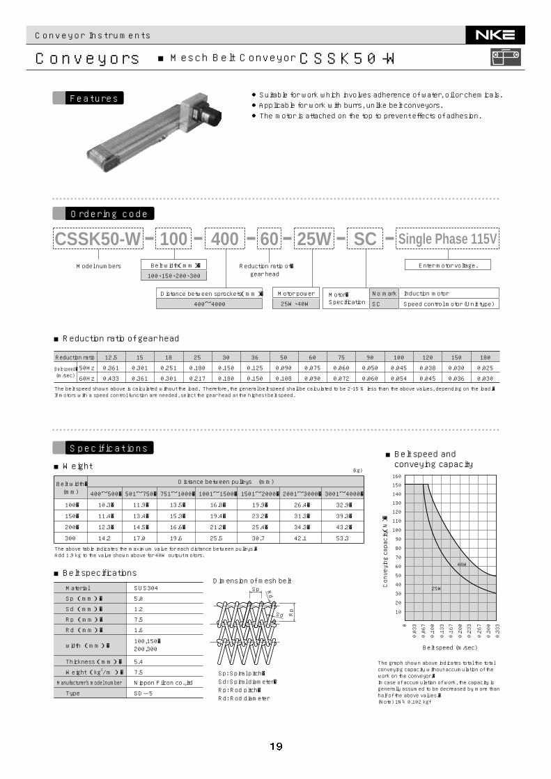
Conveyors ■Mesch Belt Conveyor CSSK50-W
Belt width(mm)�
100、150、200、300
Motor power
25W、40W
Model numbers Reduction ratio of�gear head
CSSK50-W 60100 25W SC400
Distance between sprockets(mm)�
400~4000Motor�Specification
No mark
SC
Induction motor
Speed control motor (Unit type)
Enter motor voltage.
Single Phase 115V
Sp: Spiral pitch�Sd: Spiral diameter�Rp: Rod pitch�Rd: Rod diameter
Rp
Sp
Sd
Rd
Dimension of mesh belt
Conveying capacity(N)�
Belt speed (m/sec)
25W
40W
10
20
30
40
50
60
70
80
90
100
110
120
130
140
150
160
0.0330
0.067
0.100
0.133
0.167
0.200
0.233
0.267
0.300
0.333
The belt speed shown above is calculated without the load. Therefore, the general belt speed shall be calculated to be 2-15 % less than the above values, depending on the load.�If motors with a speed control function are needed, select the gear head at the highest belt speed.
Material SUS304
Sp (mm)�
Sd (mm)�
Rp (mm)� 7.5
Rd (mm)�
Weight (kg / m )�
width (mm)�100,150�200,300
Thickness(mm)� 5.4
Manufacturer's model number Nippon Filcon co.,itd
Type
Reduction ratio
50Hz
60Hz
180
0.025
0.030
150
0.030
0.036
120
0.038
0.045
100
0.045
0.054
90
0.050
0.060
75
0.060
0.072
60
0.075
0.090
50
0.090
0.108
36
0.125
0.150
30
0.150
0.180
25
0.180
0.217
18
0.251
0.301
15
0.301
0.361
12.5
0.361
0.433
SD-5
Belt speed�(m/sec)
5.0
1.2
1.6
7.52
The graph shown above indicates total the total conveying capacity without accumulation of the work on the conveyor.�In case of accumulation of work, the capacity is generally assumed to be decreased by more than half of the above values.�(Note) 1N≒0.102 kgf
100�
150�
200�
300
400~500�
10.3�
11.4�
12.3�
14.2
501~750�
11.9�
13.4�
14.5�
17.0
751~1000�
13.5�
15.3�
16.6�
19.6
1001~1500�
16.8�
19.4�
21.2�
25.5
1501~2000�
19.9�
23.2�
25.4�
30.7
2001~3000�
26.4�
31.3�
34.3�
42.1
3001~4000�
32.9�
39.3�
43.2�
53.3
Distance between pulleys (mm)
(kg)
Belt width�(mm)
The above table indicates the maximum value for each distance between pulleys.�Add 1.9 kg to the value shown above for 40W output motors.
●Suitable for work which involves adherence of water, oil or chemicals.●Applicable for work with burrs, unlike belt conveyors.●The motor is attached on the top to prevent effects of adhesion.
■Reduction ratio of gear head
■Weight
■Belt specifications
■Belt speed andconveying capacity
Ordering code
Features
Specifications
Conveyor Instruments
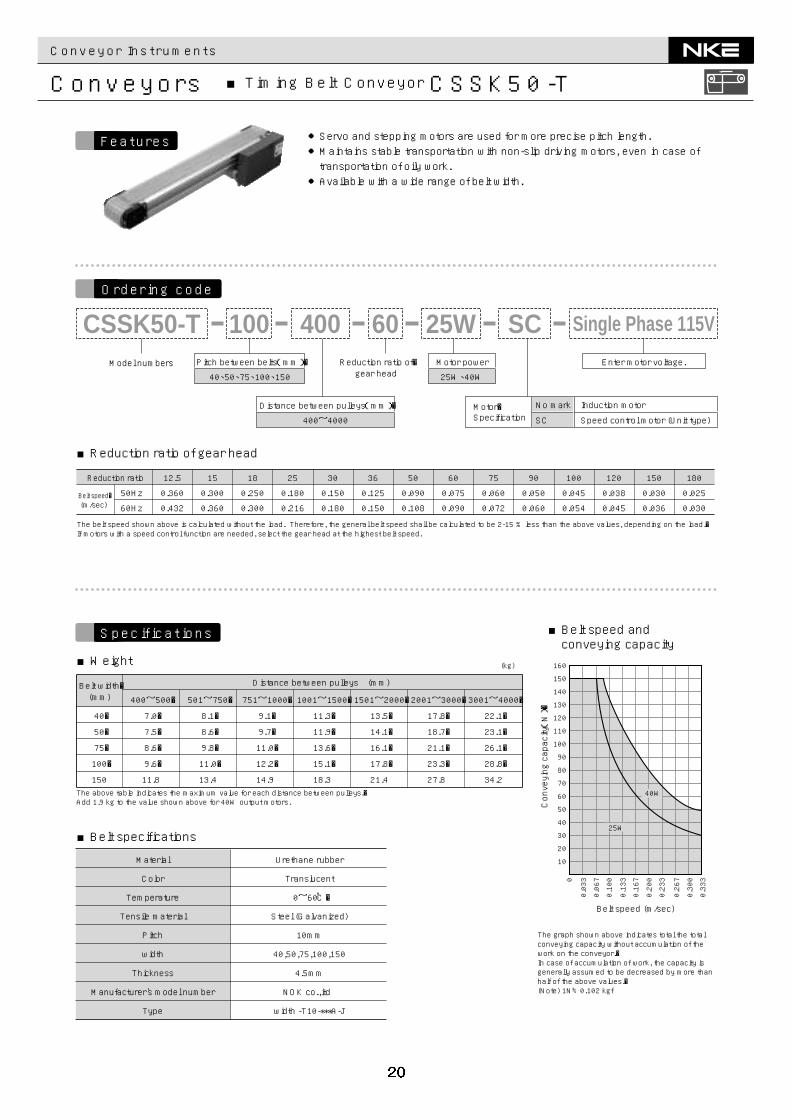
Conveyors ■Timing Belt Conveyor CSSK50-T
Reduction ratio of�gear head
Pitch between belts(mm)�
40、50、75、100、150
Distance between pulleys(mm)�
400~4000
Motor power
25W、40WModel numbers
CSSK50-T 60400100 25W SC
Motor�Specification
No mark
SC
Induction motor
Speed control motor (Unit type)
Enter motor voltage.
Single Phase 115V
●Servo and stepping motors are used for more precise pitch length.●Maintains stable transportation with non-slip driving motors, even in case oftransportation of oily work.●Available with a wide range of belt width.
Conveying capacity(N)�
Belt speed (m/sec)
10
20
30
40
50
60
70
80
90
100
110
120
130
140
150
160
0.0330
0.067
0.100
0.133
0.167
0.200
0.233
0.267
0.300
0.333
The graph shown above indicates total the total conveying capacity without accumulation of the work on the conveyor.�In case of accumulation of work, the capacity is generally assumed to be decreased by more than half of the above values.�(Note) 1N≒0.102 kgf
40�
50�
75�
100�
150
400~500�
7.0�
7.5�
8.6�
9.6�
11.8
501~750�
8.1�
8.6�
9.8�
11.0�
13.4
751~1000�
9.1�
9.7�
11.0�
12.2�
14.9
1001~1500�
11.3�
11.9�
13.6�
15.1�
18.3
1501~2000�
13.5�
14.1�
16.1�
17.8�
21.4
2001~3000�
17.8�
18.7�
21.1�
23.3�
27.8
3001~4000�
22.1�
23.1�
26.1�
28.8�
34.2
Distance between pulleys (mm)
(kg)
Belt width�(mm)
The above table indicates the maximum value for each distance between pulleys.�Add 1.9 kg to the value shown above for 40W output motors.
40W
25W
Temperature
Tensile material
Pitch
Urethane rubber
Translucent
0~60℃�
10mm
width 40,50,75,100,150
Thickness 4.5mm
Manufacturer's model number NOK co.,itd
Type width -T10-***A-J
Steel (Galvanized)
Material
Color
Reduction ratio
50Hz
60Hz
180
0.025
0.030
150
0.030
0.036
120
0.038
0.045
100
0.045
0.054
90
0.050
0.060
75
0.060
0.072
60
0.075
0.090
50
0.090
0.108
36
0.125
0.150
30
0.150
0.180
25
0.180
0.216
18
0.250
0.300
15
0.300
0.360
12.5
0.360
0.432Belt speed�(m/sec)
The belt speed shown above is calculated without the load. Therefore, the general belt speed shall be calculated to be 2-15 % less than the above values, depending on the load.�If motors with a speed control function are needed, select the gear head at the highest belt speed.
■Reduction ratio of gear head
■Weight
■Belt speed andconveying capacity
■Belt specifications
Ordering code
Features
Specifications
Conveyor Instruments
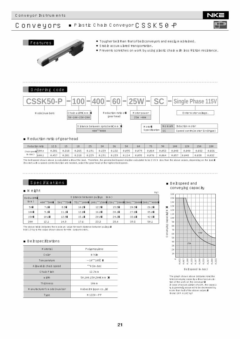
Conveyors ■Plastic Chain Conveyor CSSK50-P
Distance between sprockets(mm)�
400~4000
Model numbers
CSSK50-P 400100Reduction ratio of�gear head
Motor power
25W、40W
60 25W SCChain width(mm)�
50、100、150、200
Motor�Specification
No mark
SC
Induction motor
Speed control motor (Unit type)
Enter motor voltage.
Single Phase 115V
●Tougher belt than that of belt conveyors and easily maintained.●Stable accumulated transportation.●Prevents scratches on work by using plastic chain with less friction resistance.
Conveying capacity(N)�
Belt speed (m/sec)
10
20
30
40
50
60
70
80
90
100
110
120
130
140
150
160
0.0330
0.067
0.100
0.133
0.167
0.200
0.233
0.267
0.300
0.333
50�
100�
150�
200
400~500�
7.6�
9.1�
10.6�
12.1
501~750�
8.9�
11.1�
12.9�
14.9
751~1000�
10.2�
12.8�
15.1�
17.6
1001~1500�
12.9�
16.8�
20.0�
23.3
1501~2000�
15.5�
20.1�
24.2�
28.4
2001~3000�
20.9�
27.8�
33.6�
39.5
3001~4000�
26.3�
35.0�
42.5�
50.1
Distance between pulleys (mm)
(kg)
Belt width�(mm)
The above table indicates the maximum value for each distance between pulleys.�Add 1.9 kg to the value shown above for 40W output motors.
The graph shown above indicates total the total conveying capacity without accumula-tion of the work on the conveyor.�In case of accumulation of work, the capaci-ty is generally assumed to be decreased by more than half of the above values.�(Note) 1N≒0.102 kgf
40W
25W
Color
Temperature
Allowable chain speed
Chain Pitch
Material Polypropylene
White
-10~105℃�
12.7mm
width 50,100,150,200(mm)�
Thickness 10mm
Manufacturer's model number Habasit Nippon co.,itd
Type M1220-PP
~0.5m/sec
Reduction ratio
50Hz
60Hz
180
0.026
0.032
150
0.032
0.038
120
0.040
0.048
100
0.048
0.057
90
0.053
0.064
75
0.064
0.076
60
0.079
0.095
50
Chain speed�(m/sec)
0.095
0.114
36
0.132
0.159
30
0.159
0.191
25
0.191
0.229
18
0.265
0.318
15
0.318
0.381
12.5
0.381
0.457
The belt speed shown above is calculated without the load. Therefore, the general belt speed shall be calculated to be 2-15 % less than the above values, depending on the load.�If motors with a speed control function are needed, select the gear head at the highest belt speed.
■Reduction ratio of gear head
■Weight
■Belt speed andconveying capacity
■Belt specifications
Ordering code
Features
Specifications
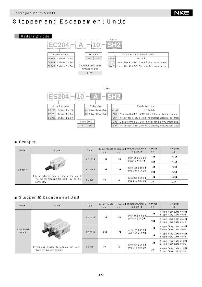
Proximity switch
2 sets of the NSH-24V (Check for the forwarding end)
4 sets of the NSH-24V (Check for the forwarding and backwarding ends)
2 sets of the NSV-24V (Check for the forwarding end)
4 sets of the NSV-24V (Check for the forwarding and backwarding ends)
No Switch
2 sets of the NSV-24V (Check for the forwarding end)
Switch to check the both ends
2 sets of the NSH-24V (Check for the forwarding end)
No Switch
Conveyor Instruments
Stopper and Escapement Units
■Stopper
■Stopper & Escapement Unit
Shape
●An attachment can be fixed on the top of the rod for stopping the work flow on the conveyor.
Stopper
Model
EC203�
EC204�
EC206
15�
20�
30
9�
12�
15
push 85{8.6}�pull 55{5.6}�
10�
20�
10�
20�
10�
20
0.11�
0.16�
0.22�
0.35�
0.29�
0.42
push 155{15}�pull 100{10}�
push 350{35}�pull 265{27}�
Weight�kg
Stroke�mm
Theoretical force� N{kgf}�
Rod diameter�mm
Cylinder bore�mm
Type
Shape
●This unit is used to separate the work flowing in jam one by one.
Stopper &�Escape
ES203�
ES204�
ES206
15�
20�
30
9�
12�
15
push 85{8.6}�pull 55{5.6}�
A-type fixing plate:0.30�B-type fixing plate:0.33
A-type fixing plate:0.40�B-type fixing plate:0.43
A-type fixing plate:0.55�B-type fixing plate:0.61
A-type fixing plate:0.81�B-type fixing plate:0.87
A-type fixing plate:0.83�B-type fixing plate:0.95
A-type fixing plate:1.07�B-type fixing plate:1.21
10�
20�
10�
20�
10�
20
push 155{15}�pull 100{10}�
push 350{35}�pull 265{27}�
ModelWeight�kg
Stroke�mm
Theoretical force� N{kgf}�
Rod diameter�mm
Cylinder bore�mm
Type
Model numbers
EC203 Cylinder IDφ15
EC204 Cylinder IDφ20
EC206 Cylinder IDφ30
Stroke (mm)
10 20
SH2
No mark
SV2Orientation of the planefor fixing the load
A~D
Option
A@@@@@@@@e?@@@@@@@@e?@@h?@@h?@@h?@@h?@@h?@@h?
@@@@@@@@e?@@@@@@@@?e@@@@@@@@e?@@@@@@@@?e@@@@@@@@e?@@@@@@@@?e@@@@@@@@e?@@@@@@@@?e@@@@@@@@e?@@@@@@@@?e@@@@@@@@e?@@@@@@@@?e@@@@@@@@e?@@@@@@@@?e@@@@@@@@e?@@@@@@@@?e@@@@@@@@e?@@@@@@@@?e@@@@@@@@e?@@@@@@@@?e
@@@@@@@@@@@@@@@@@@@@@@@@@@@@
@@@@@@@@@@@@@@@@
@@@@@@@@@@@@@@@@
@@@@@@@@@@@@@@@@
@@@@@@@@@@@@@@@@
@@@@@@@@@@@@@@@@
@@@@@@@@@@@@@@@@
@@@@@@@@@@@@@@@@
?@@?@@?@@?@@?@@?@@
?@@@@@@@@?@@@@@@@@
?@@@@@@@@?e@@@@@@@@e?@@@@@@@@?e@@@@@@@@e?@@@@@@@@?e@@@@@@@@e?@@@@@@@@?e@@@@@@@@e?@@@@@@@@?e@@@@@@@@?@@@@@@@@?e@@@@@@@@e?@@@@@@@@?e@@@@@@@@e?@@@@@@@@?e@@@@@@@@e?@@@@@@@@?e@@@@@@@@e?@@@@@@@@?e@@@@@@@@
@@g@@g@@g@@g@@g@@g@@@@@@@@@@@@@@@@
@@@@@@@@@@@@@@@@
@@@@@@@@@@@@@@@@
@@@@@@@@@@@@@@@@
@@@@@@@@@@@@@@@@
@@@@@@@@@@@@@@@@
@@@@@@@@@@@@@@@@
@@@@@@@@@@@@@@@@
10@@@@@@@@e?@@@@@@@@e?@@h?@@h?@@h?@@h?@@h?@@h?
@@@@@@@@e?@@@@@@@@?e@@@@@@@@e?@@@@@@@@?e@@@@@@@@e?@@@@@@@@?e@@@@@@@@e?@@@@@@@@?e@@@@@@@@e?@@@@@@@@e?@@@@@@@@?e@@@@@@@@e?@@@@@@@@?e@@@@@@@@e?@@@@@@@@?e@@@@@@@@e?@@@@@@@@?e@@@@@@@@e?
@@@@@@@@@@@@@@@@@@@@@@@@@@@@
@@@@@@@@@@@@@@@@
@@@@@@@@@@@@@@@@
@@@@@@@@@@@@@@@@
@@@@@@@@@@@@@@@@
@@@@@@@@@@@@@@@@
@@@@@@@@@@@@@@@@
@@@@@@@@@@@@@@@@
?@@?@@?@@?@@?@@?@@
?@@@@@@@@?@@@@@@@@
?@@@@@@@@?e@@@@@@@@e?@@@@@@@@?e@@@@@@@@e?@@@@@@@@?e@@@@@@@@e?@@@@@@@@?e@@@@@@@@e?@@@@@@@@?@@@@@@@@?e@@@@@@@@e?@@@@@@@@?e@@@@@@@@e?@@@@@@@@?e@@@@@@@@e?@@@@@@@@?e@@@@@@@@e?@@@@@@@@
@@g@@g@@g@@g@@g@@g@@@@@@@@@@@@@@@@
@@@@@@@@@@@@@@@@
@@@@@@@@@@@@@@@@
@@@@@@@@@@@@@@@@
@@@@@@@@@@@@@@@@
@@@@@@@@@@@@@@@@
@@@@@@@@@@@@@@@@
@@@@@@@@@@@@@@@@
EC204@@@@@@@@e?@@@@@@@@e?@@h?@@h?@@h?@@h?@@h?@@h?
@@@@@@@@e?@@@@@@@@?e@@@@@@@@e?@@@@@@@@?e@@@@@@@@e?@@@@@@@@?e@@@@@@@@e?@@@@@@@@?e@@@@@@@@e?@@@@@@@@?e@@@@@@@@e?@@@@@@@@?e@@@@@@@@e?@@@@@@@@?e@@@@@@@@e?@@@@@@@@?e@@@@@@@@e?@@@@@@@@?e@@@@@@@@e?@@@@@@@@?e@@@@@@@@e?@@@@@@@@?e@@@@@@@@e?@@@@@@@@e?@@@@@@@@?e@@@@@@@@e?@@@@@@@@?e@@@@@@@@e?@@@@@@@@?e@@@@@@@@e?@@@@@@@@?e@@@@@@@@e?@@@@@@@@?e@@@@@@@@e?@@@@@@@@?e@@@@@@@@e?@@@@@@@@?e@@@@@@@@e?@@@@@@@@?e@@@@@@@@e?@@@@@@@@?e@@@@@@@@e?@@@@@@@@?e@@@@@@@@e?@@@@@@@@?e@@@@@@@@e?
@@@@@@@@@@@@@@@@@@@@@@@@@@@@
@@@@@@@@@@@@@@@@
@@@@@@@@@@@@@@@@
@@@@@@@@@@@@@@@@
@@@@@@@@@@@@@@@@
@@@@@@@@@@@@@@@@
@@@@@@@@@@@@@@@@
@@@@@@@@@@@@@@@@
?@@?@@?@@?@@?@@?@@
?@@@@@@@@?@@@@@@@@
?@@@@@@@@?e@@@@@@@@e?@@@@@@@@?e@@@@@@@@e?@@@@@@@@?e@@@@@@@@e?@@@@@@@@?e@@@@@@@@e?@@@@@@@@?e@@@@@@@@e?@@@@@@@@?e@@@@@@@@e?@@@@@@@@?e@@@@@@@@e?@@@@@@@@?e@@@@@@@@e?@@@@@@@@?e@@@@@@@@e?@@@@@@@@?e@@@@@@@@e?@@@@@@@@?e@@@@@@@@e?@@@@@@@@?@@@@@@@@?e@@@@@@@@e?@@@@@@@@?e@@@@@@@@e?@@@@@@@@?e@@@@@@@@e?@@@@@@@@?e@@@@@@@@e?@@@@@@@@?e@@@@@@@@e?@@@@@@@@?e@@@@@@@@e?@@@@@@@@?e@@@@@@@@e?@@@@@@@@?e@@@@@@@@e?@@@@@@@@?e@@@@@@@@e?@@@@@@@@?e@@@@@@@@e?@@@@@@@@?e@@@@@@@@e?@@@@@@@@
@@g@@g@@g@@g@@g@@g@@@@@@@@@@@@@@@@
@@@@@@@@@@@@@@@@
@@@@@@@@@@@@@@@@
@@@@@@@@@@@@@@@@
@@@@@@@@@@@@@@@@
@@@@@@@@@@@@@@@@
@@@@@@@@@@@@@@@@
@@@@@@@@@@@@@@@@
SH2@@@@@@@@e?@@@@@@@@e?@@h?@@h?@@h?@@h?@@h?@@h?
@@@@@@@@e?@@@@@@@@?e@@@@@@@@e?@@@@@@@@?e@@@@@@@@e?@@@@@@@@?e@@@@@@@@e?@@@@@@@@?e@@@@@@@@e?@@@@@@@@?e@@@@@@@@e?@@@@@@@@?e@@@@@@@@e?@@@@@@@@?e@@@@@@@@e?@@@@@@@@e?@@@@@@@@?e@@@@@@@@e?@@@@@@@@?e@@@@@@@@e?@@@@@@@@?e@@@@@@@@e?@@@@@@@@?e@@@@@@@@e?@@@@@@@@?e@@@@@@@@e?@@@@@@@@?e@@@@@@@@e?@@@@@@@@?e@@@@@@@@e?
@@@@@@@@@@@@@@@@@@@@@@@@@@@@
@@@@@@@@@@@@@@@@
@@@@@@@@@@@@@@@@
@@@@@@@@@@@@@@@@
@@@@@@@@@@@@@@@@
@@@@@@@@@@@@@@@@
@@@@@@@@@@@@@@@@
@@@@@@@@@@@@@@@@
?@@?@@?@@?@@?@@?@@
?@@@@@@@@?@@@@@@@@
?@@@@@@@@?e@@@@@@@@e?@@@@@@@@?e@@@@@@@@e?@@@@@@@@?e@@@@@@@@e?@@@@@@@@?e@@@@@@@@e?@@@@@@@@?e@@@@@@@@e?@@@@@@@@?e@@@@@@@@e?@@@@@@@@?e@@@@@@@@e?@@@@@@@@?@@@@@@@@?e@@@@@@@@e?@@@@@@@@?e@@@@@@@@e?@@@@@@@@?e@@@@@@@@e?@@@@@@@@?e@@@@@@@@e?@@@@@@@@?e@@@@@@@@e?@@@@@@@@?e@@@@@@@@e?@@@@@@@@?e@@@@@@@@e?@@@@@@@@
@@g@@g@@g@@g@@g@@g@@@@@@@@@@@@@@@@
@@@@@@@@@@@@@@@@
@@@@@@@@@@@@@@@@
@@@@@@@@@@@@@@@@
@@@@@@@@@@@@@@@@
@@@@@@@@@@@@@@@@
@@@@@@@@@@@@@@@@
@@@@@@@@@@@@@@@@
Model numbers
ES203 Cylinder IDφ15
ES204 Cylinder IDφ20
ES206 Cylinder IDφ30
Stroke (mm)
10 20
Fixing plate
A A-type fixing plate
B B-type fixing plate SH2
No mark
SH4
SV2
SV4
10@@@@@@@@e?@@@@@@@@e?@@h?@@h?@@h?@@h?@@h?@@h?
@@@@@@@@e?@@@@@@@@?e@@@@@@@@e?@@@@@@@@?e@@@@@@@@e?@@@@@@@@?e@@@@@@@@e?@@@@@@@@?e@@@@@@@@e?@@@@@@@@e?@@@@@@@@?e@@@@@@@@e?@@@@@@@@?e@@@@@@@@e?@@@@@@@@?e@@@@@@@@e?@@@@@@@@?e@@@@@@@@e?
@@@@@@@@@@@@@@@@@@@@@@@@@@@@
@@@@@@@@@@@@@@@@
@@@@@@@@@@@@@@@@
@@@@@@@@@@@@@@@@
@@@@@@@@@@@@@@@@
@@@@@@@@@@@@@@@@
@@@@@@@@@@@@@@@@
@@@@@@@@@@@@@@@@
?@@?@@?@@?@@?@@?@@
?@@@@@@@@?@@@@@@@@
?@@@@@@@@?e@@@@@@@@e?@@@@@@@@?e@@@@@@@@e?@@@@@@@@?e@@@@@@@@e?@@@@@@@@?e@@@@@@@@e?@@@@@@@@?@@@@@@@@?e@@@@@@@@e?@@@@@@@@?e@@@@@@@@e?@@@@@@@@?e@@@@@@@@e?@@@@@@@@?e@@@@@@@@e?@@@@@@@@
@@g@@g@@g@@g@@g@@g@@@@@@@@@@@@@@@@
@@@@@@@@@@@@@@@@
@@@@@@@@@@@@@@@@
@@@@@@@@@@@@@@@@
@@@@@@@@@@@@@@@@
@@@@@@@@@@@@@@@@
@@@@@@@@@@@@@@@@
@@@@@@@@@@@@@@@@
ES204@@@@@@@@e?@@@@@@@@e?@@h?@@h?@@h?@@h?@@h?@@h?
@@@@@@@@e?@@@@@@@@?e@@@@@@@@e?@@@@@@@@?e@@@@@@@@e?@@@@@@@@?e@@@@@@@@e?@@@@@@@@?e@@@@@@@@e?@@@@@@@@?e@@@@@@@@e?@@@@@@@@?e@@@@@@@@e?@@@@@@@@?e@@@@@@@@e?@@@@@@@@?e@@@@@@@@e?@@@@@@@@?e@@@@@@@@e?@@@@@@@@?e@@@@@@@@e?@@@@@@@@?e@@@@@@@@e?@@@@@@@@e?@@@@@@@@?e@@@@@@@@e?@@@@@@@@?e@@@@@@@@e?@@@@@@@@?e@@@@@@@@e?@@@@@@@@?e@@@@@@@@e?@@@@@@@@?e@@@@@@@@e?@@@@@@@@?e@@@@@@@@e?@@@@@@@@?e@@@@@@@@e?@@@@@@@@?e@@@@@@@@e?@@@@@@@@?e@@@@@@@@e?@@@@@@@@?e@@@@@@@@e?@@@@@@@@?e@@@@@@@@e?
@@@@@@@@@@@@@@@@@@@@@@@@@@@@
@@@@@@@@@@@@@@@@
@@@@@@@@@@@@@@@@
@@@@@@@@@@@@@@@@
@@@@@@@@@@@@@@@@
@@@@@@@@@@@@@@@@
@@@@@@@@@@@@@@@@
@@@@@@@@@@@@@@@@
?@@?@@?@@?@@?@@?@@
?@@@@@@@@?@@@@@@@@
?@@@@@@@@?e@@@@@@@@e?@@@@@@@@?e@@@@@@@@e?@@@@@@@@?e@@@@@@@@e?@@@@@@@@?e@@@@@@@@e?@@@@@@@@?e@@@@@@@@e?@@@@@@@@?e@@@@@@@@e?@@@@@@@@?e@@@@@@@@e?@@@@@@@@?e@@@@@@@@e?@@@@@@@@?e@@@@@@@@e?@@@@@@@@?e@@@@@@@@e?@@@@@@@@?e@@@@@@@@e?@@@@@@@@?@@@@@@@@?e@@@@@@@@e?@@@@@@@@?e@@@@@@@@e?@@@@@@@@?e@@@@@@@@e?@@@@@@@@?e@@@@@@@@e?@@@@@@@@?e@@@@@@@@e?@@@@@@@@?e@@@@@@@@e?@@@@@@@@?e@@@@@@@@e?@@@@@@@@?e@@@@@@@@e?@@@@@@@@?e@@@@@@@@e?@@@@@@@@?e@@@@@@@@e?@@@@@@@@?e@@@@@@@@e?@@@@@@@@
@@g@@g@@g@@g@@g@@g@@@@@@@@@@@@@@@@
@@@@@@@@@@@@@@@@
@@@@@@@@@@@@@@@@
@@@@@@@@@@@@@@@@
@@@@@@@@@@@@@@@@
@@@@@@@@@@@@@@@@
@@@@@@@@@@@@@@@@
@@@@@@@@@@@@@@@@
Option
A@@@@@@@@e?@@@@@@@@e?@@h?@@h?@@h?@@h?@@h?@@h?
@@@@@@@@e?@@@@@@@@?e@@@@@@@@e?@@@@@@@@?e@@@@@@@@e?@@@@@@@@?e@@@@@@@@e?@@@@@@@@?e@@@@@@@@e?@@@@@@@@?e@@@@@@@@e?@@@@@@@@?e@@@@@@@@e?@@@@@@@@?e@@@@@@@@e?@@@@@@@@?e@@@@@@@@e?@@@@@@@@?e@@@@@@@@e?@@@@@@@@?e
@@@@@@@@@@@@@@@@@@@@@@@@@@@@
@@@@@@@@@@@@@@@@
@@@@@@@@@@@@@@@@
@@@@@@@@@@@@@@@@
@@@@@@@@@@@@@@@@
@@@@@@@@@@@@@@@@
@@@@@@@@@@@@@@@@
@@@@@@@@@@@@@@@@
?@@?@@?@@?@@?@@?@@
?@@@@@@@@?@@@@@@@@
?@@@@@@@@?e@@@@@@@@e?@@@@@@@@?e@@@@@@@@e?@@@@@@@@?e@@@@@@@@e?@@@@@@@@?e@@@@@@@@e?@@@@@@@@?e@@@@@@@@?@@@@@@@@?e@@@@@@@@e?@@@@@@@@?e@@@@@@@@e?@@@@@@@@?e@@@@@@@@e?@@@@@@@@?e@@@@@@@@e?@@@@@@@@?e@@@@@@@@
@@g@@g@@g@@g@@g@@g@@@@@@@@@@@@@@@@
@@@@@@@@@@@@@@@@
@@@@@@@@@@@@@@@@
@@@@@@@@@@@@@@@@
@@@@@@@@@@@@@@@@
@@@@@@@@@@@@@@@@
@@@@@@@@@@@@@@@@
@@@@@@@@@@@@@@@@
SH2@@@@@@@@e?@@@@@@@@e?@@h?@@h?@@h?@@h?@@h?@@h?
@@@@@@@@e?@@@@@@@@?e@@@@@@@@e?@@@@@@@@?e@@@@@@@@e?@@@@@@@@?e@@@@@@@@e?@@@@@@@@?e@@@@@@@@e?@@@@@@@@?e@@@@@@@@e?@@@@@@@@?e@@@@@@@@e?@@@@@@@@?e@@@@@@@@e?@@@@@@@@e?@@@@@@@@?e@@@@@@@@e?@@@@@@@@?e@@@@@@@@e?@@@@@@@@?e@@@@@@@@e?@@@@@@@@?e@@@@@@@@e?@@@@@@@@?e@@@@@@@@e?@@@@@@@@?e@@@@@@@@e?@@@@@@@@?e@@@@@@@@e?
@@@@@@@@@@@@@@@@@@@@@@@@@@@@
@@@@@@@@@@@@@@@@
@@@@@@@@@@@@@@@@
@@@@@@@@@@@@@@@@
@@@@@@@@@@@@@@@@
@@@@@@@@@@@@@@@@
@@@@@@@@@@@@@@@@
@@@@@@@@@@@@@@@@
?@@?@@?@@?@@?@@?@@
?@@@@@@@@?@@@@@@@@
?@@@@@@@@?e@@@@@@@@e?@@@@@@@@?e@@@@@@@@e?@@@@@@@@?e@@@@@@@@e?@@@@@@@@?e@@@@@@@@e?@@@@@@@@?e@@@@@@@@e?@@@@@@@@?e@@@@@@@@e?@@@@@@@@?e@@@@@@@@e?@@@@@@@@?@@@@@@@@?e@@@@@@@@e?@@@@@@@@?e@@@@@@@@e?@@@@@@@@?e@@@@@@@@e?@@@@@@@@?e@@@@@@@@e?@@@@@@@@?e@@@@@@@@e?@@@@@@@@?e@@@@@@@@e?@@@@@@@@?e@@@@@@@@e?@@@@@@@@
@@g@@g@@g@@g@@g@@g@@@@@@@@@@@@@@@@
@@@@@@@@@@@@@@@@
@@@@@@@@@@@@@@@@
@@@@@@@@@@@@@@@@
@@@@@@@@@@@@@@@@
@@@@@@@@@@@@@@@@
@@@@@@@@@@@@@@@@
@@@@@@@@@@@@@@@@
Ordering code
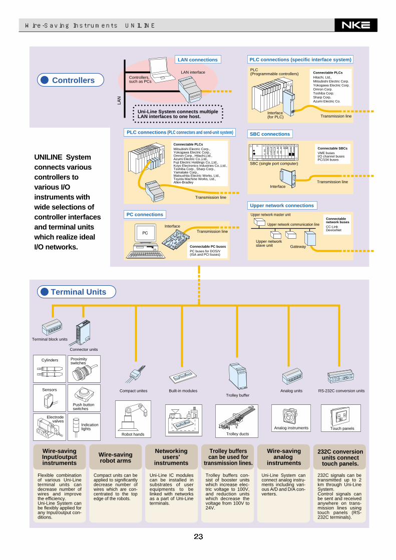
Wire-Saving Instruments UNILINE
Connectable PLCsHitachi, Ltd.,Mitsubishi Electric Corp.Yokogawa Electric Corp.Omron Corp.Toshiba Corp.Sharp Corp.Azumi Electric Co.
Connectable PLCsMitsubishi Electric Corp.,Yokogawa Electric Corp.,Omron Corp., Hitachi,Ltd.,Azumi Electric Co.,Ltd.,Fuji Electric Holdings Co.,Ltd.,Koyo Electronics Industries Co.,Ltd.,Toshiba Corp., Sharp Corp.,Yamatake Corp.,Matsushita Electric Works, Ltd.,Toyota Machine Works, Ltd.,Allen-Bradley
UNILINE System connects various controllers to various I/O instruments with wide selections of controller interfaces and terminal units which realize ideal I/O networks.
232C signals can be transmitted up to 2 km through Uni-Line System.Control signals can be sent and received anywhere on trans-mission lines using touch panels (RS-232C terminals).
Uni-Line System can connect analog instru-ments including vari-ous A/D and D/A con-verters.
Trolley buffers con-sist of booster units which increase elec-tric voltage to 100V, and reduction units which decrease the voltage from 100V to 24V.
Uni-Line IC modules can be installed in substrates of user equipments to be linked with networks as a part of Uni-Line terminals.
Compact units can be applied to significantly decrease number of wires which are con-centrated to the top edge of the robots.
Flexible combination of various Uni-Line terminal units can decrease number of wires and improve the efficiency.Uni-Line System can be flexibly applied for any Input/output con-ditions.
Controllers Controllers, such as PCs
LAN interfacePLC(Programmable controllers)
Interface(for PLC)
SBC (single port computer)
Interface
Upper network master unit
Upper networkslave unit Gateway
Transmission line
Transmission line
Transmission line
Transmission lineInterface
Terminal block units
Wire-savingInput/outputinstruments
Wire-savingrobot arms
Networkingusers'
instruments
Trolley bufferscan be used for
transmission lines.
Wire-savinganalog
instruments
232C conversionunits connecttouch panels.
Cylinders
Sensors
Electrodevalves
Proximityswitches
Push buttonswitches
Indicationlights
Connector units
Compact unites
Robot hands
Built-in modulesTrolley buffer
Analog units RS-232C conversion units
Touch panelsAnalog instruments
Trolley ducts
Uni-Line System connects multipleLAN interfaces to one host.
PLC connections (PLC connectors and send-unit system)
PLC connections (specific interface system)
SBC connections
Upper network connections
LAN connections
PC connections
Terminal Units
Connectable SBCsVME busesI/O channel busesPC/104 buses
Connectablenetwork busesCC-LinkDeviceNet
Connectable PC busesPC buses for DOS/V(ISA and PCI buses)
Upper network communication line
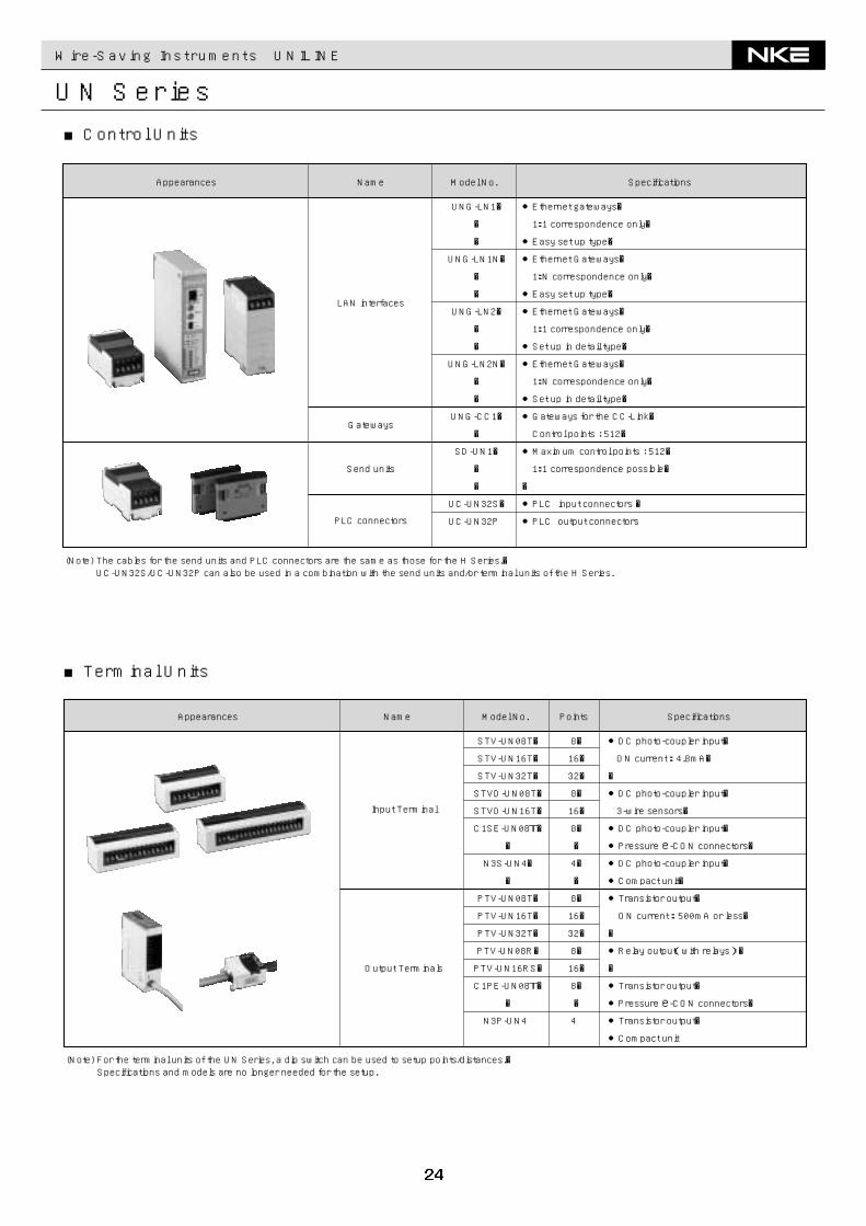
Appearances SpecificationsModel No.
●Ethernet gateways�
1:1 correspondence only�
●Easy set up type�
●Ethernet Gateways�
1:N correspondence only�
●Easy set up type�
●Ethernet Gateways�
1:1 correspondence only�
●Set up in detail type�
●Ethernet Gateways�
1:N correspondence only�
●Set up in detail type�
●Gateways for the CC-Link�
Control points : 512�
●Maximum control points : 512�
1:1 correspondence possible�
�
●PLC input connectors �
●PLC output connectors
UNG-LN1�
�
�
UNG-LN1N�
�
�
UNG-LN2�
�
�
UNG-LN2N�
�
�
UNG-CC1�
�
SD-UN1�
�
�
UC-UN32S�
UC-UN32P
(Note) The cables for the send units and PLC connectors are the same as those for the H Series.� UC-UN32S/UC-UN32P can also be used in a combination with the send units and/or terminal units of the H Series.
Name
LAN interfaces
Send units
Gateways
PLC connectors
●DC photo-coupler input�
ON current : 4.8mA�
�
●DC photo-coupler input�
3-wire sensors�
●DC photo-coupler input�
●Pressure e-CON connectors�●DC photo-coupler input�
●Compact unit�
●Transistor output�
ON current : 500mA or less�
�
●Relay output(with relays) �
�
●Transistor output�
●Pressure e-CON connectors�●Transistor output�
●Compact unit
STV-UN08T�
STV-UN16T�
STV-UN32T�
STVD-UN08T�
STVD-UN16T�
C1SE-UN08T�
�
N3S-UN4�
�
PTV-UN08T�
PTV-UN16T�
PTV-UN32T�
PTV-UN08R�
PTV-UN16RS�
C1PE-UN08T�
�
N3P-UN4
Points
8�
16�
32�
8�
16�
8�
�
4�
�
8�
16�
32�
8�
16�
8�
�
4
(Note) For the terminal units of the UN Series, a dip switch can be used to setup points/distances.� Specifications and models are no longer needed for the setup.
Output Terminals
Input Terminal
Appearances SpecificationsModel No.Name
Wire-Saving Instruments UNILINE
UN Series■Control Units
■Terminal Units
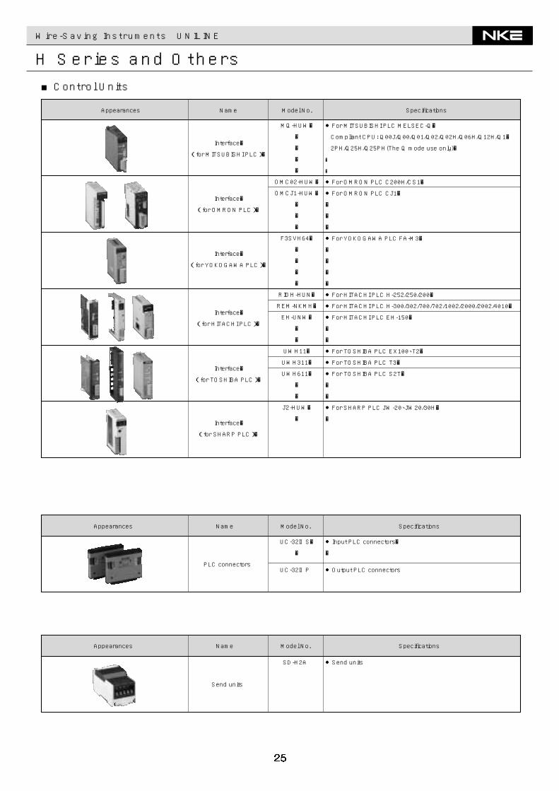
●Input PLC connectors�
�
●Output PLC connectors
UC-32ⅡS�
�
UC-32ⅡP
●Send unitsSD-H2A
PLC connectors
Send units
Appearances SpecificationsModel No.Name
Appearances SpecificationsModel No.Name
●For MITSUBISHI PLC MELSEC-Q�
Compliant CPU: Q00J/Q00/Q01/Q02/Q02H/Q06H/Q12H/Q1�
2PH/Q25H/Q25PH(The Q mode use only)�
�
�
●For OMRON PLC C200H/CS1�
●For OMRON PLC CJ1�
�
�
�
●For YOKOGAWA PLC FA-M3�
�
�
�
�
●For HITACHI PLC H-252/250/200�
●For HITACHI PLC H-300/302/700/702/1002/2000/2002/4010�
●For HITACHI PLC EH-150�
�
�
●For TOSHIBA PLC EX100、T2�
●For TOSHIBA PLC T3�
●For TOSHIBA PLC S2T�
�
�
●For SHARP PLC JW-20、JW20/30H�
�
MQ-HUW�
�
�
�
�
OMC02-HUW�
OMCJ1-HUW�
�
�
�
F3SVH64�
�
�
�
�
RIOH-HUN�
REM-NKMH�
EH-UNW�
�
�
UWH11�
UWH311�
UWH611�
�
�
J2-HUW�
�
Interface�
(for HITACHI PLC)�
Interface�
(for MITSUBISHI PLC)�
Interface�
(for OMRON PLC)�
Interface�
(for YOKOGAWA PLC)�
Interface�
(for TOSHIBA PLC)�
Interface�
(for SHARP PLC)�
Appearances SpecificationsModel No.Name
Wire-Saving Instruments UNILINE
H Series and Others■Control Units
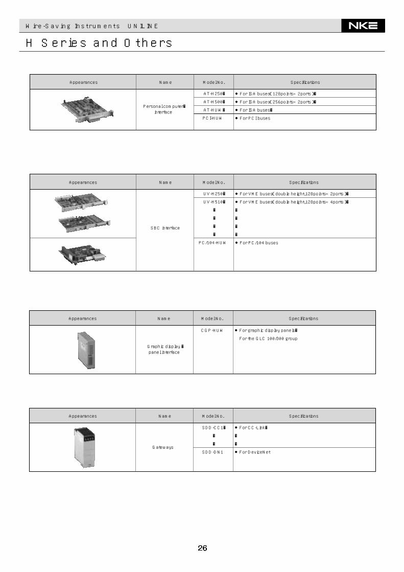
Wire-Saving Instruments UNILINE
H Series and Others
●For ISA buses(128points×2ports)�
●For ISA buses(256points×2ports)�
●For ISA buses�
●For PCI buses
AT-H250�
AT-H500�
AT-HUW�
PCI-HUW
Personal computer�interface
Appearances SpecificationsModel No.Name
●For VME buses(double height,128points×2ports)�
●For VME buses(double height,128points×4ports)�
�
�
�
�
●For PC/104 buses
UV-H250�
UV-H510�
�
�
�
�
PC/104-HUW
SBC interface
Appearances SpecificationsModel No.Name
●For graphic display panels�
For the GLC 100/300 group
CGP-HUW
Graphic display �panel interface
Appearances SpecificationsModel No.Name
●For CC-Link�
�
�
●For DeviceNet
SDD-CC1�
�
�
SDD-DN1Gateways
Appearances SpecificationsModel No.Name
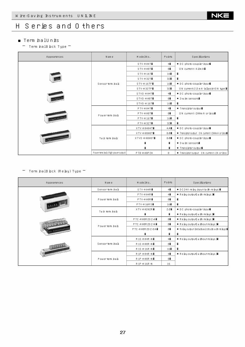
Wire-Saving Instruments UNILINE
H Series and Others
■Terminal Units─ Terminal Block Type ─
─ Terminal Block (Relay) Type ─
●DC photo-coupler input�
ON current : 4.8mA�
�
�
●DC photo-coupler input�
ON current: 2.5 mA (all-point ON type)�
●DC photo-coupler input�
●3-wire sensors�
�
●Transistor output�
ON current : 200mA or less�
�
�
●DC photo-coupler input�
●Transistor output ON current : 200mA or less�
●DC photo-coupler input�
●3-wire sensors�
●Transistor output�
●Transistor output ON current : 2A or less
4�
8�
16�
32�
16�
32�
4�
8�
16�
4�
8�
16�
32�
4/4�
8/8�
8/8�
�
�
8
STV-H04T�
STV-H08T�
STV-H16T�
STV-H32T�
STV-H16TF�
STV-H32TF�
STVD-H04T�
STVD-H08T�
STVD-H16T�
PTV-H04T�
PTV-H08T�
PTV-H16T�
PTV-H32T�
XTV-H0404T�
XTV-H0808T�
XTVD-H0808T�
�
�
PTB-H08P2A
Sensor terminals
Power terminals
Twin terminals
Power terminals (high power output)
Appearances SpecificationsModel No.Name Points
●DC24V relay input (with relays)�
●Relay output(with relays)�
�
�
●DC photo-coupler input�
●Relay output(with relays)�
●Relay output(with relays)�
●Relay output(without relays)�
●Relay output (individual circuits with relays)�
�
●Relay output(without relays)�
�
�
●Relay output(without relays)�
4�
4�
8�
16�
2/2�
�
8�
8�
8�
�
4�
8�
16�
4�
8�
16
STV-H04R�
PTV-H04R�
PTV-H08R�
PTV-H16RS�
XTV-H0202R�
�
PTC-H08R2D2-A�
PTC-H08R2D2-N�
PTC-H08R2D2-SA�
�
R1S-H04R-N�
R1S-H08R-N�
R1S-H16R-N�
R1P-H04R-N�
R1P-H08R-N�
R1P-H16R-N
Sensor terminals
Power terminals
Twin terminals
Power terminals
Sensor terminals
Power terminals
Appearances SpecificationsModel No.Name Points
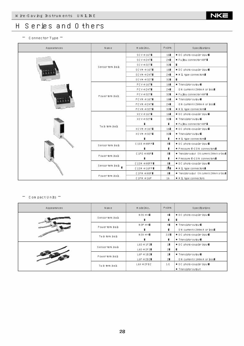
Wire-Saving Instruments UNILINE
H Series and Others─ Connector Type ─
─ Compact Units ─
●DC photo-coupler input�
●Fujitsu connector 40P�
�
●DC photo-coupler input�
●MIL type connectors�
�
●Transistor output�
ON current : 200mA or less�
●Fujitsu connector 40P�
●Transistor output�
ON current : 200mA or less�
●MIL type connectors�
●DC photo-coupler input�
●Transistor output�
●Fujitsu connector 40P�
●DC photo-coupler input�
●Transistor output�
●MIL type connectors�
●DC photo-coupler input�
●Pressure e-CON connectors�●Transistor output ON current : 200mA or less�
●Pressure e-CON connectors�●DC photo-coupler input�
●MIL type connectors�
●Transistor output ON current : 200mA or less�
●MIL type connectors
16�
24�
32�
16�
24�
32�
16�
24�
32�
16�
24�
32�
16�
32�
�
16�
32�
�
8�
�
8�
�
8�
16�
8�
16
SCV-H16T�
SCV-H24T�
SCV-H32T�
SCVM-H16T�
SCVM-H24T�
SCVM-H32T�
PCV-H16T�
PCV-H24T�
PCV-H32T�
PCVM-H16T�
PCVM-H24T�
PCVM-H32T�
XCV-H16T�
XCV-H32T�
�
XCVM-H16T�
XCVM-H32T�
�
C1SE-H08FP�
�
C1PE-H08P�
�
C1SM-H08FP�
C1SM-H16FP�
C1PM-H08P�
C1PM-H16P
��
Sensor terminals
Power terminals
Twin terminals
Sensor terminals
Power terminals
Sensor terminals
Power terminals
Appearances SpecificationsModel No.Name Points
●DC photo-coupler input�
�
●Transistor output�
ON current : 200mA or less�
●DC photo-coupler input�
●Transistor output�
●DC photo-coupler input�
�
●Transistor output�
ON current : 100mA or less�
●DC photo-coupler input�
●Transistor output
4�
�
4�
�
2/2�
�
1�
2�
1�
2�
1/1
N3S-H4�
�
N3P-H4�
�
N3X-H4�
�
L6S-H1F2�
L6S-H2F2�
L6P-H1B2�
L6P-H2B2�
L6X-H2FB2
Sensor terminals
Power terminals
Twin terminals
Sensor terminals
Power terminals
Twin terminals
Appearances SpecificationsModel No.Name Points
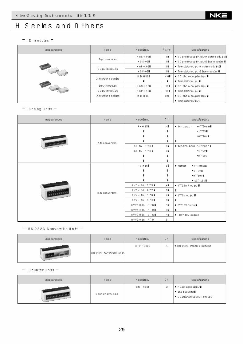
Wire-Saving Instruments UNILINE
H Series and Others
●DC photo-coupler input(Master modules)�
●DC photo-coupler input(Slave modules)�
●Transistor output(Master modules)�
●Transistor output(Slave modules)�
●DC photo-coupler input�
●Transistor output�
●DC photo-coupler input�
●Transistor output�
●DC photo-coupler input�
●Transistor output
8�
8�
8�
8�
4/4�
�
16�
16�
8/8
MAS-H08�
MOS-08�
MAP-H08�
MOP-08�
MIX-H08�
�
MAS-H16�
MAP-H16�
MIX-H16
Input modules
Output modules
In/Output modules
Input modules
Output modules
In/Output modules
Appearances SpecificationsModel No.Name Points
─ IC modules ─
─ Analog Units ─
─RS-232C Conversion Units ─
●4ch input ・4~20mA�
・1~5V�
・0~10V�
�
●4ch/8ch input ・4~20mA�
・1~5V�
・0~10V
4�
�
�
�
4�
8�
�
�
1�
�
�
�
4�
8�
4�
8�
4�
8�
4�
8
AX-H15�
�
�
�
AX-16 E~G�
AX-16 A~D�
�
�
AY-H15�
�
�
�
AYC-H16 E~G�
AYC-H16 A~D�
AYV-H16 E~G�
AYV-H16 A~D�
AYV1-H16 E~G�
AYV1-H16 A~D�
AYV2-H16 E~G�
AYV2-H16 A~D
A/D converters
●output ・4~20mA�
・1~5V�
・0~10V�
・-10~10V�
●4~20mA output�
�
●1~5V output�
�
●0~10V output�
�
●-10~10V output
D/A converters
Appearances SpecificationsModel No.Name Ch
●RS-232C transmit / receive1XTV-H232C
RS-232C conversion units
Appearances SpecificationsModel No.Name Ch
─ Counter Units ─
●Pulse signal input�
●16bit counter�
●Calculation speed : 500cps
2CNT-H02F
Counter terminals
Appearances SpecificationsModel No.Name Ch
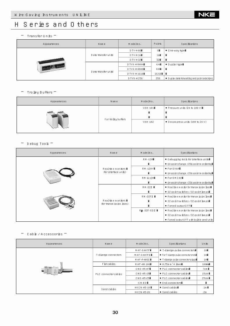
Wire-Saving Instruments UNILINE
H Series and Others─ Transfer Units ─
─ Trolley Buffers ─
─ Debug Tools ─
●One-way type�
�
�
●Duplex type�
�
�
●Duplex data forwarding and point selections
8�
16�
32�
4/4�
8/8�
16/16�
256
DTV-H08�
DTV-H16�
DTV-H32�
DTVX-H0404�
DTVX-H0808�
DTVX-H1616�
DTVX-H256
Data transfer units
Data transfer units
Appearances SpecificationsModel No.Name Points
●Pressure units (24 to 100 V)�
�
�
●Decompress units (100 to 24 V)
VAH-101�
�
�
VAH-102
Appearances SpecificationsModel No.Name
For trolley buffers
●Debugging tools for interface units�
●64-point change / 256-point monitoring�
●For SV64�
●64-point change / 256-point monitoring�
●For OMC02�
●64-point change / 256-point monitoring�
●Real time monitor for transmission lines�
●32-point switches / 32-point lamps�
●Real time monitor for transmission lines�
●32-point switches / 32-point lamps�
●Forced output OFF�
●Real time monitor for transmission lines�
●32-point switches / 32-point lamps�
●Forced output OFF with built-in send units
RM-120�
�
RM-120Y�
�
RM-Q120�
�
RM-32Ⅱ�
�
RM-32FⅡ�
�
�
RM-32F-SDⅡ��
Real time monitors �(for interface units)
Real time monitors �(for transmission lines)
Appearances SpecificationsModel No.Name
─ Cable / Accessories ─
●T-diverge pulse connectors�
●For T-diverge pulse connector ends�
●T-diverge pulse connector plugs�
●0.75mm2 4 lines�
●PLC connector cables�
●PLC connector cables�
●PLC connector cables�
●End connectors�
●Send cables�
●Send cables
10�
10�
10�
100m�
7cm�
15cm�
25cm�
�
1m�
2m
MAF-S407F�
MAF-S407FE�
MAF-P405C�
MAF-4M100�
CND-05-07�
CND-05-15�
CND-05-25�
CN-ED�
HKCN-05-1K�
HKCN-05-2K
T-diverge connectors
Flat cables
Send cables
PLC connector cables
Appearances Specifications UnitsModel No.Name