Embed Size (px)
Citation preview
8 L A H O U I L L E B L A N C H E N" 1 - .TANV.-FÉV. 1956
Dissipation de l'énergie sur les ouvrages hydrauliques de haute chute
par le dissipateur à double effet
Dissipation of energy at high head hydraulic structures by double jet dissipator
H . L . U P P A L
M. Sc., Ph. D., F.N.I.
P A R
E T G A J I N D E E S I N G H
M. Sc.
La dissipation d'énergie à l'aval des ouvrages hydrauliques tels que èvacuateurs, seuils, déversoirs, etc., est en général obtenue par la formation' d'un ressaut. Ceci requiert une profondeur d'eau minimum à l'anal, profondeur qu'il n'est pas possible d'obtenir dans tous les cas. Un nouveau type de dissipateur à double effet a donc été mis au point. C'est un déflecteur crénelé dont les interstices se prolongent vers l'aval afin de former une seconde série de déflecteurs. Il est installé en un point convenable sur le parement d'un êva-cuateur ou d'un seuil. La nappe s'ècoulant le long du parement est fractionnée en un grand nombre de jets qui réagissent les uns sur les autres dans l'air et dissipent de l'énergie. Une caractéristique importante du dissipateur à double effet est qu'il ne présente aucune saillie A l'intérieur du jet à grande vitesse, et qu'il ne provoque aucun changement brusque de direction de l'écoulement.
C'est sur les modèles existants de l'évacuateur de. crue du barrage de Bhakra que furent mises au point diverses dispositions du dissipateur d'énergie, tels que espacement des redans, position et ouverture du secon'd déflecteur, évase-ment des interstices, etc., etc. Un projet bien au point a ainsi pu être élaboré. Dans certains cas la profondeur des affonillements a été réduite de plus de 90 %.
Energy dissipation below hydraulic structures such as spillways, falls, weirs, etc., is generally brought about by the formation of a hydraulic, jump. This requires a certain minimum depth of water at the downstream end. This may not be obtainable in all cases. A new type of dissipator known as Double Jet Dissipator has been developed. It is a corrugated deflector with the troughs extended further downstream of the crests to form a second series of deflectors. It is constructed at a suitable point on the slope of a spillway or a fall. Flow takin'g place down the glacis is split up into a number of jets which interact with each other in the air and dissipate energy. An important feature of the Double Jet Dissipator is that it has neither any pail projecting into the high velocity jet nor does it in'volve any sudden change in the. direction of flow. Different aspects of the energy dissipator such as the spacing of the crests and troughs, position and angle of the second deflector, flare of the extensions, etc., were investigated on the existing hydraulic models of Bhakra Dam over-flow spillway. A suitable design' has been evolved. Che experiments have shown this to be very efficient. The depth of scour in some cases has been reduced by over 90 %.
I N T R O D U C T I O N
L a m a î t r i s e des effets des n a p p e s déversan tes et, p a r conséquen t , de l 'érosion des fonds à l 'aval des ouvrages h y d r a u l i q u e s est u n p rob lème d 'une i m p o r t a n c e cons idérab le p o u r l ' ingén ieur d ' i r r i ga t ion . D a n s ce r ta ins cas, il se fo rme à l 'ext rc-
I N T R O D U C T I O N
T h e p r o b l e m of con t ro l l ing t h e ac t ion of fa l l ing w a t e r a n d c o n s e q u e n t l y the bed scour below h y d r a u l i c s t r u c t u r e s is of p a r a m o u n t i m p o r t a n c e to a n I r r i ga t i on Eng inee r . In ce r ta in cases deep scour holes form at the d o w n s t r e a m end of the
Article published by SHF and available at http://www.shf-lhb.org or http://dx.doi.org/10.1051/lhb/1956017
JANV.-FÉV. 1 9 5 6 - N ° 1 L A H O U I L L E B L A N C H E 9
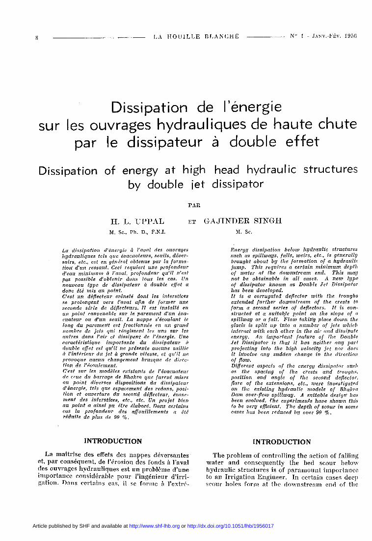
mile aval des ouvrages de p ro fondes fosses d'af-fouil leinent . De tel les fosses n ' a p p a r a i s s e n t p a s s eu lemen t d a n s des fonds a l luv iaux , m a i s on t éga lement été r e n c o n t r é e s effect ivement d a n s le cas de fonds r o c h e u x (fig. 1). Des frais considérab les son t engagés p o u r la r emi se en é ta t f réquente ou l ' en t re t i en de tels ouvrages .
w o r k s . T h e s e scour holes do no t occur below w o r k s on a l luv ia l beds only b u t a r e expe r i enced even in r o c k y beds (fig. 1) . L a r g e s u m s of m o n e y a r e spen t on f r e q u e n t r e p a i r s a n d m a i n t e n a n c e of s u c h w o r k s .
F o r low h e a d d a m s , we i r s , b a r r a g e s , falls and
FIG. 1. — Scour hole in rocky bed.
Affolliliements dans un lit rocheux.
P o u r les ouv rages de basse c h u t e (ba r rages d é v e r s a n t s ; seu i l s ; b a r r a g e s mob i l e s ; ouvrages de c h u t e ) , on a m i s au p o i n t et on ut i l i se cour a m m e n t c o m m e d i s s i p a t e u r s des éc rans en m a çonner i e c o n t i n u s [1] ou d i s con t i nus [ 2 ] , des den t s Rehbock [ 3 ] , des blocs en ch icanes [ 4 ] , etc . R é c e m m e n t , N A R A S I M H A M [5] a éga l emen t réa l i sé u n déflecteur noyé en fo rme de cui l ler qu i , const ru i t à l ' ex t r émi té d u r a d i e r aval , p rovoque u n e in t e rac t ion des j e t s et u n e r ed i s t r i bu t i on des filets à v i tesse é levée; il en r é s u l t e u n e d i m i n u tion de la p r o f o n d e u r des affoui l lements . H A M I D
et M U S H Ï A Q A H M E D [6] on t mis au po in t u n « aé ro d i s s i pa t eu r ». Ils on t r e c o m m a n d é son usage s u r les r a d i e r s en p e n t e d a n s la zone d u j e t à g r a n d e vi tesse . I l r é d u i t l ' ac t ion de l 'eau d a n s la cuve t te , et p a r c o n s é q u e n t la p r o f o n d e u r des af foui l lements à l 'aval . Cependan t , p a r m i tous ces d isposi t i fs , le p l u s efficace et le p l u s la r gemen t r é p a n d u est celui q u i c o m p o r t e des r e d a n s en ch icane . I ls son t d i sposés au débu t et à la fin du r a d i e r ho r i zon ta l . Au cours des qu inze der n iè res a n n é e s , ces r e d a n s équ ipa i en t p r a t i q u e m e n t tous les ouvrages de l ' Inde. Ils sont m a i n -
level c ross ings e n e r g y d i s s i p a t i n g devices s u c h as baffle wa l l s [ 1 ] , baffle p i e r s [ 2 ] , Rhebock d e n t a t e d cill [ 3 ] , s t aggered b locks [ 4 ] , e tc . h a v e been evolved a n d a r e be ing used . Recen t ly N A R A S I M H A M [5 ] a lso developed a c u p - s h a p e s u b m e r g e d deflector w h i c h w h e n c o n s t r u c t e d a t t h e toe of s lope o n t h e D o w n s t r e a m a p r o n , c aused t h e i n t e r - ac t i on of j e t s a n d r e d i s t r i b u t i o n of h i g h veloci ty f i l amen t s ; w h i c h r e s u l t e d in t h e r e d u c t ion of d e p t h of bed scour . H A M I D a n d M U S H T A Q
A H M E D [6] h a v e developed an Aero Deflector. T h e y h a v e advoca ted i ts use on t h e s lop ing glacis i n t h e h i g h veloci ty je t . T h i s d i m i n i s h e s t h e ac t ion of t h e w a t e r in t h e b u c k e t a n d cons e q u e n t l y r e d u c e s t h e d e p t h of s cour d o w n s t r e a m .
However , of all t hese devices , t h e m o s t efficient a n d w i d e l y used is t h e s t aggered b locks . T h e s e a r e c o n s t r u c t e d a t t h e b e g i n n i n g a n d end of t h e ho r i zon t a l a p r o n . F o r t h e las t 15 y e a r s , t h e s taggered b locks h a v e been cons t ruc t ed p r a c t ical ly on all w o r k s in Ind ia . T h e s e have n o w
1 0 LA H O U T L L E B L A N C H E № 1 - JANV.-FÉV. 1 9 5 6
t e n a n t p r é v u s d a n s les p ro j e t s et en cons t i t uen t u n e p a r t i e i n t é g r a n t e .
D a n s le cas des ouvrages h y d r a u l i q u e s de h a u t e chu te , en r a i son de la va l eu r élevée des vi tesses en cause , le p rob l ème de la d i s s ipa t ion d 'énerg ie devient t r ès difficile. Les disposi t i fs convenables mis au po in t j u s q u ' à p r é s e n t sont assez r a r e s . R O B E R T S [7] t e n t a d 'y p a r v e n i r en f r a c t i o n n a n t les j e t s à g r a n d e vi tesse à l 'aide de blocs de f ract i o n n e m e n t cons t ru i t s su r le p a r e m e n t du ba r rage . Ce disposi t i f fut m i s au po in t p o u r le ba r rage Loksop en Afr ique du Sud. Sur les ba r rages de h a u t e chu te , p o u r t a n t , l 'act ion de ces blocs ne s 'avère p a s sa t i s fa i san te ca r les je ts seconda i res qu ' i l s e n g e n d r e n t p r o v o q u e n t d a n s le lit de la r iv ière d ' i m p o r t a n t s af foui l lements .
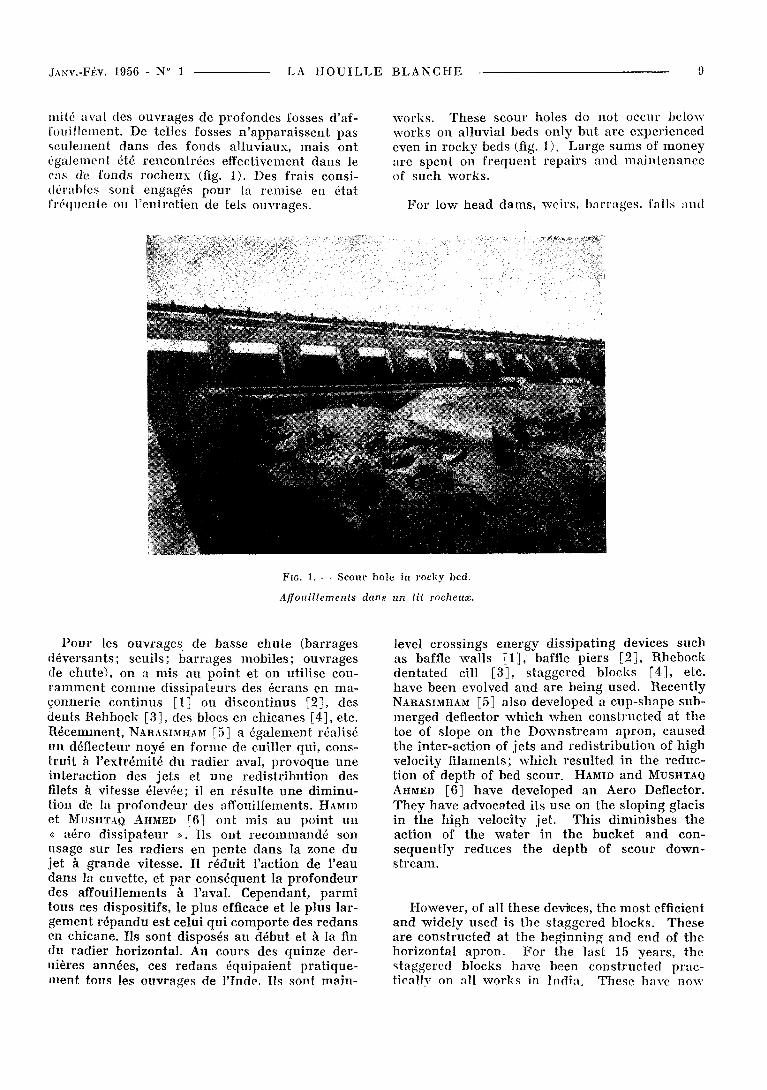
L a d i ss ipa t ion de l ' énergie au pied des ba r rages élevés est g é n é r a l e m e n t o b t e n u e grâce à u n r e s sau t , ou grâce à une cuvet te d ' a m o r t i s s e m e n t noyée du genre de celle du G r a n d Coulée. Enfin, u n e cuvet te n o n noyée, calée a u - d e s s u s du n iveau des p lus h a u t e s eaux, est par fo is adoptée (fig. 2) . Cette d i spos i t ion s'est avérée p ré fé ra -
been i nco rpo ra t ed on t h e des ign of w o r k s , as a n essent ia l pa r t .
In the case of h igh head h y d r a u l i c s t r u c t u r e s , on accoun t of t h e h igh velocit ies involved, t h e p rob l em of energy d i s s ipa t ion becomes ve ry difficult. Only a few su i tab le devices have been developed so far. R O B E R T S [7] m a d e an a t t e m p t to achieve it by sp l i t t ing u p the h igh veloci ty j e t s w i t h the he lp of " sp l i t t e r s " c o n s t r u c t e d on the face of d a m . T h e s e were developed for the Loksop D a m in Sou th Africa. On h igh d a m s , however , these sp l i t t e r s do not w o r k successfu l ly as t h e secondary fall c rea ted by the sp l i t t e r s i nduces deep scour holes in t h e r iver bed.
Diss ipa t ion of ene rgy below h igh D a m s is usua l ly b r o u g h t abou t wi th t h e help of H y d r a u l i c J u m p Apron or a s u b m e r g e d b u c k e t of G r a n d Coulee type ap ron . Besides, a free d i s c h a r g e bucke t F ig . 2, located above the h ighes t w a t e r level, is some t imes adop ted . It h a s been p re fe r red a t ce r t a in places, since it does no t fo rm a n y scour j u s t at t he toe of the d a m , a n d also m a k e s space avai lable for t h e cons t ruc t ion of p o w e r
R. l .1700 0 r
R . L . 1 6 0 0 0
R.L. 1500 0 -
Line profile of overflow spillway a free discharge bucket.
Profil d'un barrage déversant avec jet libre.
1 0 0 0 5 0 0 0 cotet du lit de la rivière_ r i v e r b e d "R'.'L. 11400
6 0 0 0
ble d a n s ce r t a ins cas , du fait qu 'e l le évite tou t affouil lement au pied m ê m e du ba r r age , et réserve a ins i , en dessous , u n e m p l a c e m e n t p o u r la cons t ruc t ion de la cen t ra le . Cependan t , s'il ne se p r o d u i t p a s d 'affoui l lements i m p o r t a n t s au p ied du b a r r a g e , il s 'en fo rme de t r è s p ro fonds u n peu p l u s loin à l 'aval, ce qu i s 'avère égalem e n t indés i rab le . P o u r t a n t , si l 'on pa rv i en t à r édu i r e sens ib lement la p r o f o n d e u r de ces affouill emen t s , ce type de seui ls dénoyés p e u t ê t re adop té d a n s u n ce r ta in n o m b r e de cas . C'est avec
houses u n d e r n e a t h . A l t h o u g h n o deep scour occurs j u s t at" t h e toe of the d a m , ve ry deep scour holes f o r m at some d i s t ance d o w n s t r e a m , w h i c h is cons idered equa l ly u n d e s i r a b l e . If, however , t he dep th of th is deep bed scour could be subs t an t i a l l y reduced , t h e free d i s c h a r g e b u c ke t could be adop ted in va r i e ty of cases . W i t h th i s object in view, a ser ies of i nves t iga t ions w a s ca r r i ed ou t bo th on smal l a n d large scale mode l s , a n d a n e w type of ene rgy d i s s ipa to r s k n o w n as double Je t Diss ipa tor , w h i c h w o u l d e l imina t e
JANV.-FIÏV. 1 9 5 6 - N" 1 L A H O U I L L E B L A N C H E 11
cel objectif en vue q u e fut m e n é e à b ien u n e série d 'essa is su r modè le à pe t i te et à g r a n d e échelle, et que fut é laboré un n o u v e a u type de d i s s ipa teur , appe lé d i s s i pa t eu r à doub le effet, qui s u p p r i m e cet i nconvén ien t du seuil dénoyé . L 'emplo i de ce disposi t i f p e u t d ' a i l l eurs h e u r e u sement s ' é t endre au cas du r a d i e r avec r e s sau t et au seuil du type noyé .
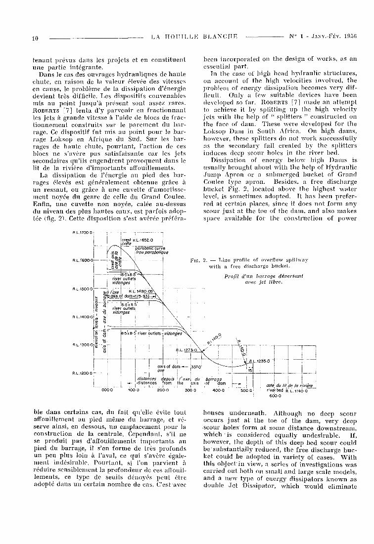
L E D I S S I P A T E U R A D O U B L E E F F E T
Le déflecteur d ' u n seuil à je t l ibre es t c rénelé . Les in te r s t i ces rése rvés en t r e les r e d a n s se p r o -
th i s h a r m f u l effect of t h e F r e e - d i s c h a r g e bucke t , w a s evolved. Besides i ts use i n t h e free d i s c h a r g e bucke t , it could also be successful ly adop ted on the H y d r a u l i c J u m p A p r o n as well as the s u b m e r g e d b u c k e t t ype a p r o n s .
T H E D O U B L E J E T D I S S I P A T O R
T h e deflector of a free d i s c h a r g e b u c k e t a t i ts free end is c o r r u g a t e d in to c res t s a n d t r o u g h s . T h e t r o u g h s be tween the c res t s a r e ex tended f u r t h e r d o w n s t r e a m to fo rm a n o the r ser ies of deflectors. W h i l e t h e spaces ex tend d o w n s t r e a m
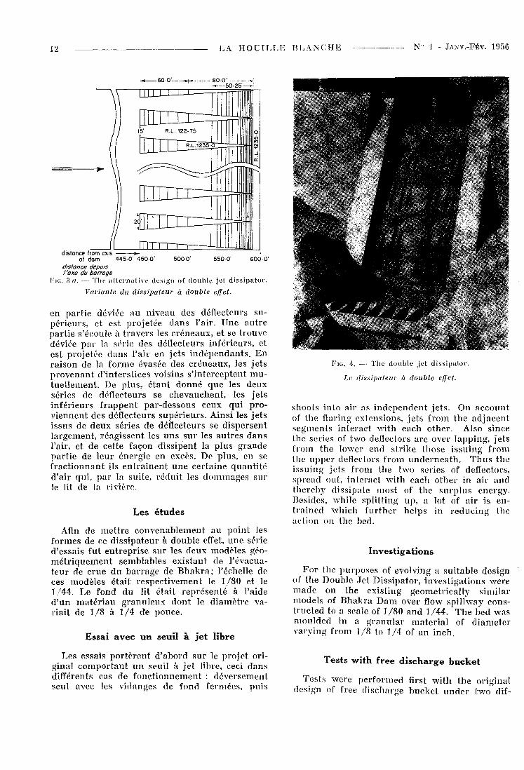
4Ö0' 450 ' 500' 550' 600 '
Fit.. 3. — Details of double jet dissipato!'.
Détails du dissipateur à double effet.
longent vers l 'aval de façon à fo rmer u n e n o u velle sér ie de déf lecteurs . T a n d i s que les in te r valles s ' é t enden t à l 'aval , ils von t en s ' é la rg i s san t de c h a q u e côté en e m p i é t a n t de p l u s en p l u s su r les crê tes con t iguës du déflecteur s u p é r i e u r (fig. 3 , ' 3 a et 4 ) . '
L o r s q u e la n a p p e d 'eau à g r a n d e vi tesse s 'écoule le long du p a r e m e n t en pen le , elle est
they flare out on e i the r s ide to cover t h e ad jo in ing c res t s of the u p p e r deflector (Fig. 3, 3 a a n d 4 ) .
As t h e fas t m o v i n g shee t of w a t e r flows d o w n Ibe s lop ing glacis , a p a r t of it gets deflected a t t he ser ies of u p p e r deflectors a n d shoo t s in to the air . A p a r t flows t h r o u g h the t r o u g h s , and gets deflected at ser ies of lower deflectors a n d
12 L A H O U I L L E B L A N C H E N " 1 - JANV. -FÉV. 195C
- * 6 0 0 ' »t— 8 0 0 ' v i
5 0 - 2 5 ' —
d i s t a n c e f r o m oxis
Of d a m 4 4 5 0 ' 4 5 0 0 ' 5 0 0 0 ' 5 5 0 0 ' 6 0 0 0 ' distance depuis l'axe du barrage
F i e 3 a. — The al ternat ive design of double jet dissipator.
Variante, du dissipateur à double effet.
en par t i e déviée au n iveau des déflecteurs supé r i eu r s , et est p ro je tée dans l 'air . Une a u t r e pa r t i e s 'écoule à t r a v e r s les c r éneaux , et se t rouve déviée p a r la sér ie des déflecteurs in fé r i eu r s , et est p ro je tée d a n s l 'a i r en j e t s i n d é p e n d a n t s . E n r a i son de la f o r m e évasée des c r éneaux , les j e t s p r o v e n a n t d ' in te r s t i ces vois ins s ' i n te rcep ten t m u tue l l emen t . De p lus , é t an t d o n n é q u e les deux séries de déf lecteurs se chevauchen t , les j e t s in fé r i eurs f r appen t p a r - d e s s o u s ceux qu i p r o v iennen t des déf lecteurs s u p é r i e u r s . Ainsi les j e t s i ssus de deux séries de déflecteurs se d i spe r sen t l a rgement , r éag i s sen t les u n s s u r les a u t r e s d a n s l 'air, et de cet te façon d i s s ipen t la p l u s g rande pa r t i e de leur énergie en excès. De p lus , en se f r ac t i onnan t ils e n t r a î n e n t u n e ce r t a ine q u a n t i t é d 'a i r qui , p a r la sui te , r é d u i t les d o m m a g e s su r le lit de la r ivière .
Les é t u d e s
Afin de m e t t r e c o n v e n a b l e m e n t au po in t les formes de ce d i s s ipa t eu r à double effet, u n e série d 'essa is fut e n t r e p r i s e su r les deux modè les géom é t r i q u e m e n t semblab les ex i s tan t de l ' évacua-t e u r de c rue d u b a r r a g e de B h a k r a ; l 'échelle de ces modèles é ta i t r e spec t ivemen t le 1/80 et le 1/44. Le fond du lit é ta i t r e p r é s e n t é à l 'aide d ' u n m a t é r i a u g r a n u l e u x don t le d i a m è t r e var ia i t de 1/8 à 1/4 de pouce .
Essai a v e c u n seui l à j e t l ibre
Les essais p o r t è r e n t d ' abord sur le p ro je t or i g inal c o m p o r t a n t u n seuil à je t l ibre, ceci d a n s différents cas de f o n c t i o n n e m e n t : déve r semen t seul avec les v idanges de fond fe rmées , pu i s
FIG. 4. — The double jet dissipator.
Le dissipateur à double effet.
shoots in to air as i n d e p e n d e n t j e t s . On a c c o u n t of the flaring ex tens ions , j e t s f rom t h e a d j a c e n t s egmen t s i n t e r ac t wi th each o ther . Also s ince the ser ies of two deflectors a r e over l app ing , j e t s f rom t h e lower end s t r ike those i s su ing f rom the u p p e r deflectors f rom u n d e r n e a t h . T h u s t h e i s su ing j e t s f rom the two series of deflectors, sp read out , i n t e r ac t w i t h each o t h e r in a i r and the reby d i ss ipa te most of t h e s u r p l u s energy . Besides, whi le sp l i t t ing up , a lot of a i r is ent r a ined w h i c h fu r the r he lps in r e d u c i n g the act ion on the bed.
Inves t i ga t ions
F o r the p u r p o s e s of evolving a su i t ab le des ign of t h e Double Je t Diss ipa tor , i nves t iga t ions were m a d e on the exis t ing geomet r i ca l ly s imi la r models of B h a k r a D a m over flow sp i l lway const ruc ted to a scale of 1/80 a n d 1/44. T h e bed was mou lded in a g r a n u l a r m a t e r i a l of d i a m e t e r v a r y i n g f rom 1/8 to 1/4 of a n i nch .
Tes t s w i t h f ree d i s c h a r g e b u c k e t
Tes t s w e r e pe r fo rmed first w i t h t h e or ig ina l des ign of free d i scharge b u c k e t u n d e r two dif-
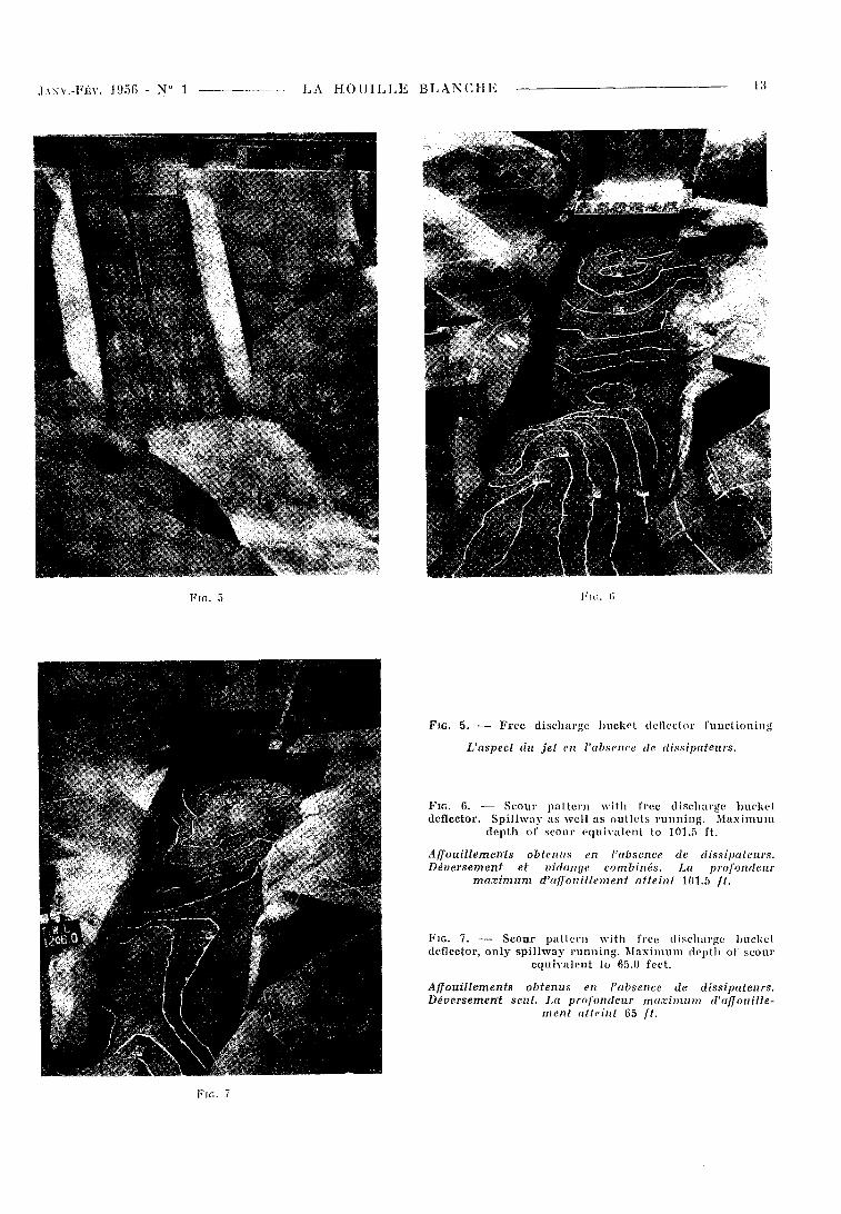
FIG. 5. — Free discharge bucket deflector functioning.
L'aspect du jet en l'absence de dissipateurs.
Fie. 6. — Scour pattern with free discharge bucket deflector. Spillway as well as outlets running. Maximum
depth of scour equivalent to 101.5 ft.
Affouillements obtenus en l'absence de dissipateurs. Déversement et vidange combinés. La profondeur
maximum d'affouillement atteint 101,5 / / .
Fie. 7. — Scour pattern with free discharge bucket deflector, only spillway running. Maximum depth of scour
equivalent to 65.0 feet.
Affouillements obtenus en l'absence de dissipateurs. Déversement seul. IM profondeur maximum d'affouille
ment atteint 65 / / .
FIG. 7
JAXV.-FÉV. 1 9 5 6 - № 1 L A H O U I L L E B L A N C H E
FIG. 5 Fie. (i
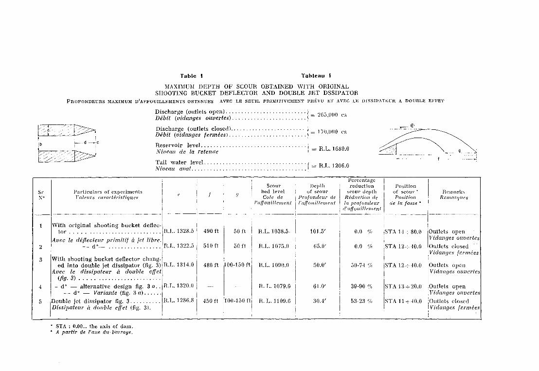
Table Tableau I
M A X I M U M D E P T H O F S C O U R O B T A I N E D W I T H O R I G I N A L S H O O T I N G B U C K E T D E F L E C T O R A N D D O U B L E J E T D S S I P A T O R
P R O F O N D E U R S MAXIMUM D'AFFOUILLEMENTS OBTENUES AVEC LE SEUIL PRIMITIVEMENT PRÉVU ET AVEC LE DISSIPATEUR A DOUBLE EFFET
Discharge (outlets open) . . . Débit (vidanges ouvertes).
Discharge (outlets closed). Débit (vidanges fermées). .
Reservoir level Niveau de la retenue
Tail water level Niveau aval
=. 21)5,000 es
= 170,000 es
= R.L. 1680.0
R.L. 1206.0
Sirs»
2
3
4
5
Part iculars of experiments Valeurs caractéristiques
With original shooting bucket deflector
Avec le déflecteur primitif à jet libre. — d ° —
With shooting bucket deflector changed into double jet dissipator (fig. 3)
Avec le dissipateur à double effet (flg.3)
— d° — alternative design fig. 3 a . . — d" — Variante (fig. 3 a)
Double jet dissipator fig. 3 Dissipateur à double effet (fig. 3).
R.L. 1328.5
R.L. 1322.5
R.L. 1314.0
R.L. 1320.0
R.L. 1286.8
/ I
490 ft
510 ft
480 ft
450 l't
50 ft
50 ft
Scoui-bed level Cote de
V aff ouillement
R.L. 1038.5
R.L. 1075.0
100-150 ft R.L. 1090.0
R. L. 1079.0
100-150 fli R.L. 1109.6
Depth of scour
Profondeur de ì'affouillement
101.5'
65.0'
50.0'
61.0'
30.4'
Percentage reduction
scour depth Réduction de la profondeur
(raff ouillement
0.0 "lo
0.0 %
50-74 %
39-90 %
53-23 %
Position of scour * Position
de la fosse *
S T A 14-1-80.0
S T A 12 -^40 . 0
S T A 12H-40 .0
S T A 13 -^20.0
S T A l l -T -40 . 0
Remarks Remarques
Outlets open Vidanges ouvertes
Outlets closed Vidanges fermées
Outlets open Vidanges ouvertes
Outlets open Vidanges ouvertes
Outlets closed Vidanges fermées
* STA : 0.00... the axis of dam. " A partir de l'axe du- barrage.
JANV.-FÉV. 1 9 5 « - № 1 l\A H O U I L L E B L A N C H E 15
déve r semen t combiné avec l ' é cou lemen t des vidanges de fond (fig. 5) .
D a n s le cas des v idanges de fond ouver tes , la p ro fondeu r m a x i m u m d 'affoui l lement ob tenue étai t de 101,5 p i e d s ; l o r sque les v idanges de fond é ta ien t fe rmées , ce t te p r o f o n d e u r a t t e igna i t 65 pieds (fig. 6, fig. 7) .
i 'erent cond i t ions of flow viz., only overflow spi l l w a y r u n n i n g ou t l e t s c losed a n d overflow sp i l lway as wel l as ou t l e t s r u n n i n g s (Fig. 5) .
M a x i m u m d e p t h of scour ob t a ined w i t h ou t l e t s open a n d w i t h ou t l e t s closed w e r e 101.5 feet a n d 65.0 feet respec t ive ly (Figs . 6 a n d 7) .
Le d i s s ipa teur à d o u b l e effet
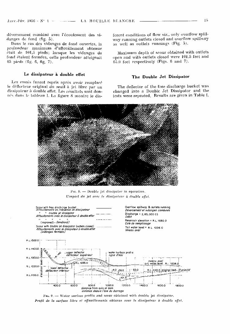
Les essais fu ren t r ep r i s a p r è s avoir r e m p l a c é le déflecteur or ig ina l du seuil à j e t libre p a r u n d i s s ipa teu r à double effet. Les r é s u l t a t s sont donnés d a n s le lableau I. La figure 8 m o n t r e le d is -
T h e D o u b l e J e t D i s s i p a t o r
T h e deflector of t h e free d i s c h a r g e b u c k e t w a s c h a n g e d i n t o a Doub le J e t D i s s i p a t o r a n d t h e t e s t s w e r e r epea ted . R e s u l t s a r e given in T a b l e I.
FIG. 8. — Double jet dissipator in operat ion.
L'aspect da jet avec le dissipateur à double effet.
Scour with free discharge bucket Overflow spillway 8 outlets running
Affouillemenls en l'absence de dissipateur Déversement et vidanges combinés
» " double jet dissipator Discharge = 2 , 6 5 , 0 0 0 es
Affouillements avec le dissipateur a double effet Z?e2v'/ , ... . , Reservoir elevation = R . L . 1 6 8 0 . 0 ( improved) - (améliore) C o t e d e r e m p l i s s a g e
Scour with double jet dissipator (outlets closed) T o i | W Q t e r | e v e , Affouillements avec le dissipateur a double effet Niveau aval
(vidanges fermées)
R L . 1 4 0 0 0 ; i <
R. L. 1200.0 F c
,p J-upper deflector K 'déflecteur supérieur
I—water surface profile ligne d'eau
niveau aval J ! D/S water level R . L . 1 2 0 6 . 0
~r.__J _{4.0 :j26.0 : f • 50.0 ; R. L J140.0 j ) r i q i n o l btà-Jit primitif
6 0 0 . 0 8 0 0 . 0 1000 .0 distance from axis of dam distance depuis l'axe du barrage
1 8 0 0 0
FIG. 9 . — Water surface profile and scour obtained with double jet dissipator .
Profil de la surface libre et affouillements obtenus avec le dissipateur à double effet.
l u L A H O U I L L E B L A N C H E N" 1 - JANV.-FÉV . 19f)(i
positif en cours de f o n c t i o n n e m e n t . A la su i te du f r a c t i o n n e m e n t des j e t s et de l ' i n te rac t ion p r o voquée p a r le d i s s ipa teur , on p u t observer ce qui su i t :
Une p a r t i m p o r t a n t e de l 'énergie en excès se t rouva i t d iss ipée . E n conséquence , le n iveau a t t e in t p a r le j e t s ' aba issa de la cote 1328 à la cote 1314; l ' é t a lement du j e t p a s s a de 50 à 100 ou 150 p i e d s ; le j e t qu i f r appa i t le lit de la r i vière su r u n e l o n g u e u r de 50 p ieds s'y é ta la i t m a i n t e n a n t su r u n e l o n g u e u r de 100 ou 150 p ieds . Ainsi avec cet te nouvel le d i spos i t ion l 'énergie é ta i t r é p a r t i e su r u n e sur face p l u s g r a n d e que d a n s le p r e m i e r cas et, p a r conséquen t , la p r o fondeur des affoui l lements s ' aba issa i t de 101 pieds à env i ron 50 p ieds (fig. 9 ) .
D e u x p ro je t s différents de d i s s i p a t e u r co r re s p o n d a n t a u x figures 3 et 3 a on t été e x a m i n é s . L a différence en t r e ces d e u x p ro j e t s es t q u e d a n s le p r e m i e r les c r é n e a u x s ' évasa ien t à p a r t i r de l ' ex t rémi té des déf lecteurs s u p é r i e u r s , a lo r s que d a n s le second cas ils c o m m e n ç a i e n t à s 'évaser dès l 'or igine de ces déf lecteurs . De ces deux p r o je t s celui qu i est p r é sen t é su r la figure 3 s 'avéra le mei l l eur . L ' a u t r e v a r i a n t e fut donc aban donnée .
Les c a r a c t é r i s t i q u e s d u d i s s ipateur à d o u b l e effet
Un cer ta in n o m b r e d 'essa is c o m p l é m e n t a i r e s furent en t r ep r i s afin de d é t e r m i n e r :
T h e func t ion ing of d i s s ipa to r is s h o w n in F ig . 8. As a r e su l t of t h e sp l i t t i ng u p a n d i n t e r a c t i o n of t h e j e t s b r o u g h t abou t by t h e d i s s ipa to r , it w a s observed t h a t :
A m a j o r p a r t of t h e s u r p l u s e n e r g y w a s dest royed. Subsequen t l y t h e r i se of t h e j e t dec reas ed f rom R.L.1328.0" to R.L.1314.0, t h e sp read ou t of the j e t i nc reased f rom 50 feet to 100 feet-150 feet; t h e j e t w h i c h used to s t r i ke t h e r iver bed in a l eng th of 50 feet, n o w m e t it in a l eng th of 100 feet to 150 feet. T h u s t h e e n e r g y w a s now d i s t r ibu ted over a far g rea t e r an a r e a t h a n in the p rev ious case a n d c o n s e q u e n t l y t h e d e p t h of scour decreased f rom 101 feet to a b o u t 50 feel. (Fig. 9) .
T w o different des igns of t h e d i s s ipa to r s (Figs . 3 a n d 3 a) we re e x a m i n e d . T h e difference in the two w a s t ha t , i n the first one t h e t h r o u g h s flare out f rom t h e end w h e r e as in t h e second case they s t a r t f lar ing ou t f rom t h e b e g i n n i n g of t h e u p p e r deflectors. Ou t of these two, t h e one s h o w n in F ig . 3 w o r k e d be t te r . T h e a l t e rna t ive design Avas t h u s a b a n d o n e d .
E l e m e n t s of t h e D o u b l e J e t D i s s i p a t o r
F u r t h e r tes t s w e r e ca r r i ed ou t to d e t e r m i n e :
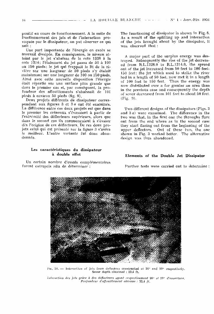
FIG. 10 . — Interaction of jets from deflectors constructed at 2 6 ° and 2 9 ° respectively. Scour depth obtained : 2 2 . 4 ft.
Interaction des jets grâce à des déflecteurs ayant respectivement 2 6 ° et 2 9 ° d'ouverture. Profondeur d'a/fonillement obtenue : 2 2 , 4 ft.
JANV.-FÉV . 1956 - № 1 LA H O U I L L E B L A N C H E 17
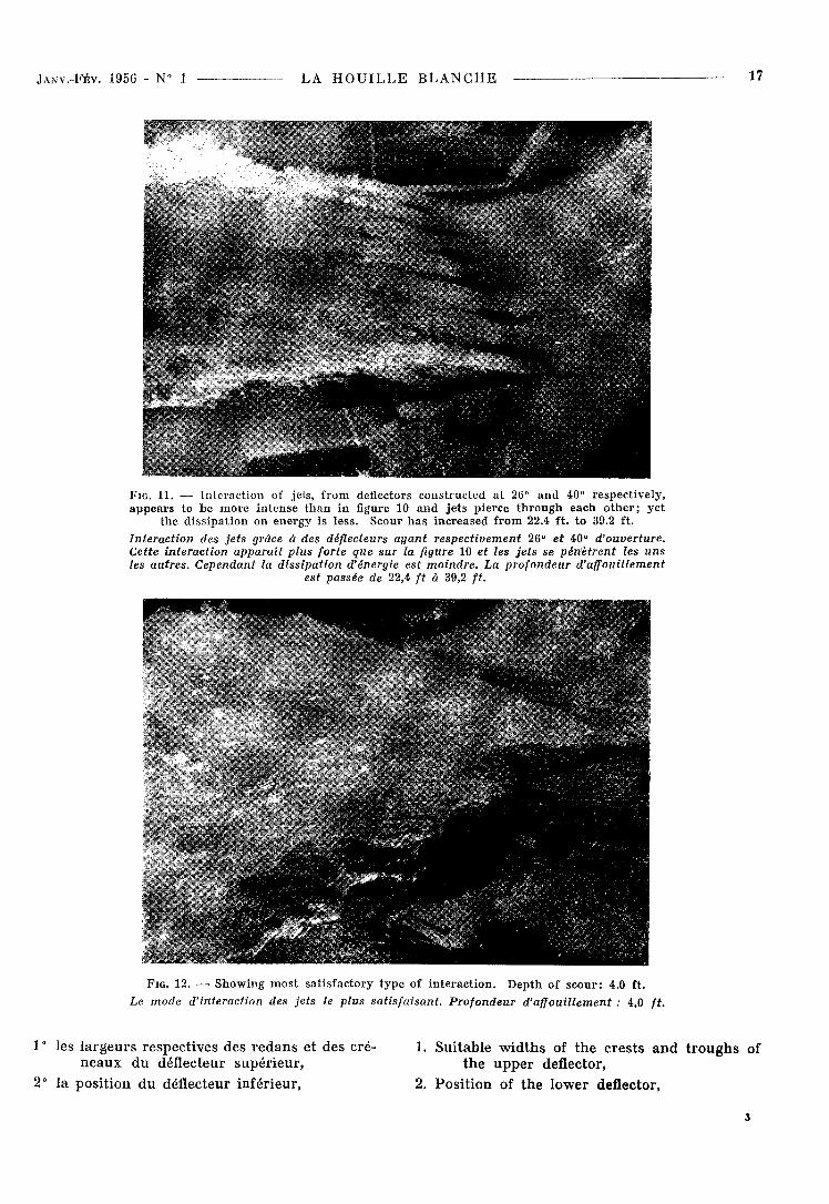
FIG. 1 1 . — Interaction of jets, from deflectors constructed at 2 6 ° and 4 0 ° respectively, appears to be more intense than in figure 1 0 and je t s pierce through each o the r ; yet
the dissipat ion on energy is less. Scour has increased from 2 2 . 4 ft. to 3 9 . 2 ft. Interaction des jets grâce à des déflecteurs ayant respectivement 2 6 ° et 4 0 ° d'ouverture. Cette interaction apparaît plus forte que sur la figure 1 0 et les jets se pénètrent les uns les autres. Cependant la dissipation d'énergie est moindre. La profondeur d'affouillement
est passée de 2 2 , 4 ft à 3 9 , 2 ft.
FIG. 1 2 . —• Showing most satisfactory type of interact ion. Depth of scour: 4 .0 ft.
Le mode d'interaction des jets le plus satisfaisant. Profondeur d'affouillement : 4 ,0 ft.
1° les l a r g e u r s respec t ives des r e d a n s e t des cré- 1. Su i tab le w i d t h s of t h e c re s t s a n d t r o u g h s of n e a u x d u déflecteur supé r i eu r , t h e u p p e r deflector,
2° la pos i t ion d u déflecteur infér ieur , 2. Pos i t i on of t h e lower deflector,
i
Table II Tableau II
M A X I M U M D E P T H O F S C O U R O B T A I N E D W I T H D I F F E R E N T C O M B I N A T I O N S O F T R O U G H S A N D C R E S T S O F U P P E R D E F L E C T O R
A N D W I T H T H E L O W E R D E F L E C T O R A T D I F F E R E N T P O S I T I O N S
P R O F O N D E U R S MAXIMUMS D'AFFOUILLEMENTS OBTENUES AVEC DIFFÉRENTES COMBINAISONS D E CREUX ET D E CRÊTES DU DÉFLECTEUR S U P É R I E U R
ET DIFFÉRENTES POSITIONS DU DÉFLECTEUR I N F É R I E U R
Discharge (outlets o p e n ) . . Débit (vidanges ouvertes).
U / S Reservoir level Niveau de la retenue . . . .
= 265,000 es
Tail water level. Niveau aval
I = R . L . 1680.0
! = R . L . 1206.0
Sr №
Par t iculars of experiments Valeurs caractéristiques e / il
Scour bed level Cote de
l'affouillement
Depth of scour
Profondeur de l'affouillement
Percentage reduction
scour depth Réduction de la profondeur d'affouillement
Posit ion of scour * Position
de la fosse * a b c d
Scour bed level Cote de
l'affouillement
Depth of scour
Profondeur de l'affouillement
Percentage reduction
scour depth Réduction de la profondeur d'affouillement
Posit ion of scour * Position
de la fosse *
1 26.5' 26.5' 53.0' 80.0' R . L . 1314.0 480.0' 150.0' R . L . 1090.4 49.6' 51.23 % STA 12^40.0
2 20.0' 15.0' 35.0' d ° R . L . 1310.0 425.0' 200' R . L . 1102.0 38.0' 62.56 % STA 11-^16.0
3 26.5' 26.5' 53.0' 45.0' R . L . 1316.0 — — R . L . 1086.8 53.2' 47.60 % STA 12-^40.0
4 26.5' 26.5' 53.0' 60.0' R. L . 1322.0 — — R . L . 1081.2 58.8' 42.07 % STA
5 15.0' 9.0' 24.0' 80.0' — - — R . L . 1076.8 63.2' 37.73 % STA 12^50.0
6 As i n i t e m n ° 4 a n d t r i a n g u l a r p i e r s at t h e c e n t r e of l o w e r def lec tor .
Comme au n°k, mais avec des piliers au centre du déflecteur inférieur.
— — R . L . 1080.0 60.0' 40.39 % STA 13-r 20.0
* Due to splashing of water , it is not qui te possible to determine wi th precision the edges of jets . Therefore, values of the r ise spread out of the je ts given in the table are approximate values . * Par suite des rejaillissements, il n'est guère possible de relever avec précision les limites des jets. Aussi les valeurs concernant l'étalement des jets sont-elles seulement approximatives.
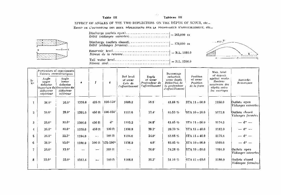
Table III Tableau III
E F F E C T O F A N G L E S O F T H E T W O D E F L E C T O R S O N T H E D E P T H O F S C O U R , etc...
E F F E T D E L'OUVERTURE DES DEUX DÉFLECTEURS S U R LA P R O F O N D E U R D'AFFOUILLEMENT , e t c . .
Discharge (outlets o p e n ) . . . Débit (vidanges ouvertes).
Discharge (outlets closed). Débit (vidanges fermées)..
Reservoir level Niveau de la retenue.
Tail water level. Niveau aval
= 265,000 es
= 170,000 es
= R.L. 1680.0
= R.L. 1206.0
Part iculars of experiments Max. level of deposit
against works Hauteur
maximum des depdts entre les ouvrages
Valeurs caractéristiques Bed level of scour Cote de
I'affouillement
Depth of scour
Profondeur de I'affouillement
Percentage reduction
scour depth Réduction de la profondeur d'affouillement
Posit ion of scour Position
de la fosse
Max. level of deposit
against works Hauteur
maximum des depdts entre les ouvrages
Sr №
Angle upper
deflector Ouverture du
déflecteur supérieur
Angle lower
deflector Ouverture du
déflecteur inférieur
e / 9
Bed level of scour Cote de
I'affouillement
Depth of scour
Profondeur de I'affouillement
Percentage reduction
scour depth Réduction de la profondeur d'affouillement
Posit ion of scour Position
de la fosse
Max. level of deposit
against works Hauteur
maximum des depdts entre les ouvrages
Remarks Remarques
1 26.0° 26.0° 1316.0 435 ft 100-150' 1080.2 59.8' 41.08 % STA 11 -4-60.0 1158.0 Outlets open Vidanges ouvertes
2 26.0° 29.0° 1291.0 450 ft 100-150' 1117.6 22.4' 65.53 % STA 10-T-20.0 1172.8 Outlets closed Vidanges fermées
3 26.0° 33.0° 1306.0 450 ft d° 1115.2 24.8' 61.85 % STA 11-4-60.0 1174.0 _ d" —
4 26.0° 40.0° 1320.0 450 ft 100ft 1100.8 39.2' 39.70 % STA ll-j-40.0 1182.0 — d° —
5 26.0" 22.5" 1294.0 — 100 ft 1116.0 24.0' 63.08 % STA 11 -4-40.0 1175.6 — d° —-
6 26.0° 13.0° 1280.0 500 ft 175-200« 1136.0 4.C 93.85 % STA 10-4-00.0 1160.0 — d« —
7 26.0° 13.0° — — 160 ft — 26.0' 74.38 % STA 10 + 60.0 1164.0 Outlets open Vidanges ouvertes
8 22.0° 33.0° 1312.4 — 100ft 1108.8 31.2' 51.10 % STA 11+60.0 1180.0 Outlets closed Vidanges fermées
2 0 L A H O U I L L E B L A N C H E N " 1 - JANV.-FÉV. 1 9 5 0
3° les ang les à d o n n e r a u x déf lecteurs s u p é r i e u r et. i n fé r i eu r .
Un g r a n d n o m b r e de c o m b i n a i s o n s différentes de l a r g e u r de c r é n e a u x et de r e d a n s fut e x a m i n é . On e s saya éga l emen t d iverses pos i t ions d u déflecteur in fé r i eu r . Le t ab l eau II d o n n e les r é s u l t a t s .
E n l i s an t a t t e n t i v e m e n t le t ab l eau II , on voit que le d i s s i p a t e u r f o n c t i o n n a n t de façon la p l u s sa t i s f a i san te c o m p r e n d u n déflecteur in fé r i eu r réal isé à u n e d i s t ance de 80 p i eds à l 'aval , e t u n déflecteur s u p é r i e u r a y a n t p o u r l a rgeu r de r e d a n s 20 p ieds , et p o u r l a r g e u r de c r é n e a u x 15 p i eds .
D ' a u t r e s essa is fu r en t e n t r e p r i s avec d ivers a n gles de déf lecteurs . On obse rva la façon d o n t les j e t s r éag i s sa i en t les u n s s u r les a u t r e s , et les p r o f o n d e u r s d 'af foui l lement ob t enues . L e t a b leau I I I d o n n e les r é s u l t a t s o b t e n u s . Les figure s 10, 11 , 12 m o n t r e n t les cond i t ions d 'écoulem e n t d a n s t ro i s cas c a r a c t é r i s t i q u e s .
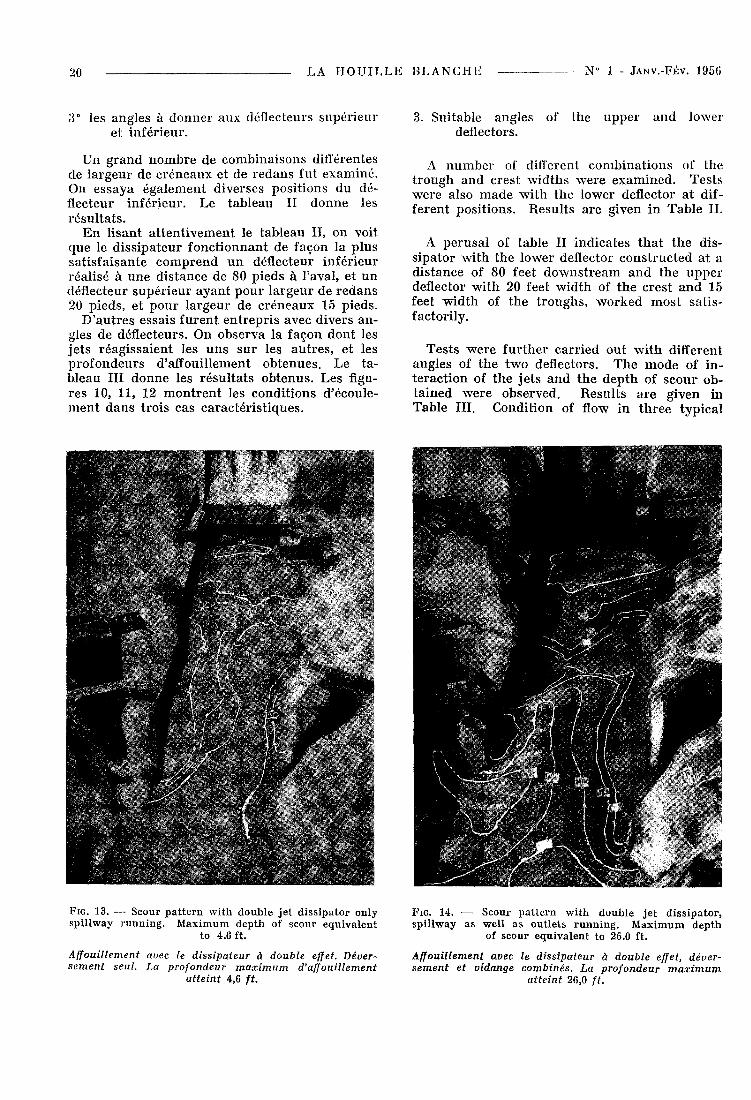
FIG . 13. — Scour pat tern wi th double j e t dissipator only spillway running. Maximum depth of scour equivalent
to 4.6 ft.
Affouillement avec le dissipateur à double effet. Déversement seul. La profondeur maximum d'affouillement
atteint 4,6 ft.
3. Sui tab le ang les of the u p p e r a n d lower deflectors.
A n u m b e r of different c o m b i n a t i o n s of the t r o u g h a n d cres t w i d t h s w e r e e x a m i n e d . Tes t s w e r e also m a d e w i t h t h e lower deflector a t diffe ren t pos i t ions . R e s u l t s a r e given in T a b l e I I .
A p e r u s a l of t ab le II i nd i ca t e s t h a t t h e d i s s ipa to r w i t h t h e lower deflector c o n s t r u c t e d a t a d i s t ance of 80 feet d o w n s t r e a m a n d t h e u p p e r deflector w i t h 20 feet w i d t h of t h e c res t a n d 15 feet w i d t h of t h e t r o u g h s , w o r k e d m o s t sa t i s factor i ly .
T e s t s w rere f u r t h e r c a r r i ed o u t w i t h different ang les of t h e t w o deflectors. T h e m o d e of in t e r a c t i o n of t h e j e t s a n d t h e d e p t h of s c o u r ob t a i n e d w e r e observed . R e s u l t s a r e g iven in Tab le I I I . Condi t ion of flow i n t h r e e typ ica l
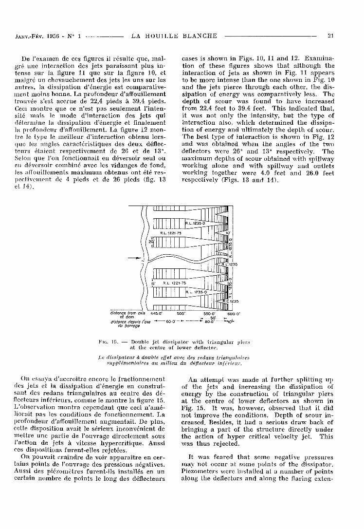
FIG. 14. — Scour pat tern wi th double je t dissipator , spil lway as well as outlets runn ing . Maximum depth
of scour equivalent to 26.0 ft.
Affouillement avec le dissipateur à double effet, déversement et vidange combinés. La profondeur maximum
atteint 26,0 ft.
JANV.-FÉV. 1 9 5 6 - № 1 LA H O U I L L E B L A N C H E 2 1
De l ' examen de ces f igures il r é su l t e que , m a l gré u n e i n t e r ac t i on des j e t s p a r a i s s a n t p l u s in t ense su r la f igure 11 que s u r la f igure 10, et m a l g r é u n c h e v a u c h e m e n t des j e t s les u n s s u r les au t r e s , la d i s s ipa t ion d ' éne rg ie es t c o m p a r a t i v e m e n t m o i n s b o n n e . L a p r o f o n d e u r d 'a f foui l lement t rouvée s'est acc rue de 22,4 p ieds à 39,4 p i eds . Ceci m o n t r e q u e ce n ' e s t p a s s e u l e m e n t l ' i n tensité m a i s le m o d e d ' i n t e r a c t i o n des j e t s q u i d é t e r m i n e la d i s s ipa t ion d 'énerg ie et f ina lement la p ro fondeu r d 'affoui l lement . L a figure 12 m o n tre le t y p e le me i l l eu r d ' i n t e r ac t i on ob t enu lo r s que les ang les c a r a c t é r i s t i q u e s des d e u x déflect eu r s é t a i en t r e s p e c t i v e m e n t de 26 et d e 13°. Selon que l 'on fonc t ionna i t en déverso i r seu l ou en déverso i r c o m b i n é avec les v idanges de fond, les a f îoui l lemenls m a x i m u m o b t e n u s on t été r e s pec t ivemen t de 4 p ieds et de 26 p ieds (fig. 13 et 14).
cases is s h o w n in F i g s . 10, 11 a n d 12. E x a m i n a t ion of t h e s e f igures show's t h a t a l t h o u g h t h e i n t e r a c t i o n of j e t s as s h o w n i n F ig . 11 a p p e a r s to be m o r e i n t e n s e t h a n t h e one s h o w n in F ig . 10 a n d t h e j e t s p i e rce t h r o u g h each o the r , t h e d i s s ipa t ion of e n e r g y w a s c o m p a r a t i v e l y less . T h e d e p t h of s cour w a s f o u n d t o h a v e i n c r e a s e d f rom 22.4 feet to 39.4 feet. T h i s i n d i c a t e d t h a t , it w a s n o t on ly t h e i n t ens i t y , b u t t h e t y p e of i n t e r a c t i o n also, w h i c h d e t e r m i n e d t h e d i s s ipa t ion of e n e r g y a n d u l t i m a t e l y t h e d e p t h of scour . T h e bes t t y p e of i n t e r a c t i o n is s h o w n in F ig . 12 a n d w a s o b t a i n e d w h e n t h e ang le s of t h e t w o deflectors w e r e 26° a n d 13° respec t ive ly . T h e m a x i m u m d e p t h s of s cour o b t a i n e d w i t h sp i l lway w o r k i n g a lone a n d w i t h sp i l lway a n d ou t l e t s w o r k i n g t o g e t h e r w e r e 4.0 feet a n d 26.0 feet respec t ive ly (Figs . 13 a n d 14).
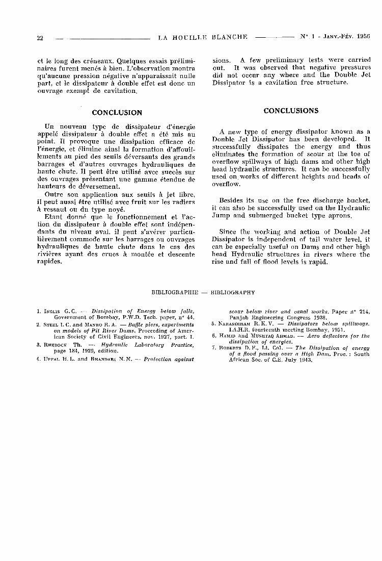
FIG. 1 5 . —• Double je t diss ipalor wi th t r i angu la r piers at the centre of lower deflector.
Le dissipateur à double effet avec des redans triangulaires supplémentaires au milieu du déflecteur inférieur.
On essaya d ' acc ro î t r e enco re le f r a c t i o n n e m e n t des j e t s et la d i s s ipa t ion d 'énerg ie en c o n s t r u i s an t des r e d a n s t r i a n g u l a i r e s a u c e n t r e des dé flecteurs in fé r i eu r s , c o m m e le m o n t r e la figure 1 5 . L'obse rva t ion m o n t r a c e p e n d a n t q u e ceci n ' a m é l iorai t p a s les cond i t ions de f o n c t i o n n e m e n t . L a p r o f o n d e u r d 'af foui l lement a u g m e n t a i t . De p lus , cette d i spos i t ion ava i t le sé r i eux i nconvén i en t de m e t t r e u n e p a r t i e de l ' ouvrage d i r e c t e m e n t sous l 'act ion de j e t s à v i tesse h y p e r c r i t i q u e . Auss i ces d i spos i t ions furent -e l les re je tées .
On pouva i t c r a i n d r e de voi r a p p a r a î t r e en cert a ins po in t s de l ' ouvrage des p r e s s ions néga t ives . Auss i des p i ézomè t re s fu ren t - i l s ins ta l l é s en u n ce r t a in n o m b r e de po in t s le long des déf lecteurs
An a t t e m p t w a s m a d e a t f u r t h e r sp l i t t i ng u p of t h e j e t s a n d i n c r e a s i n g t h e d i s s i p a t i o n of e n e r g y b y t h e c o n s t r u c t i o n of t r i a n g u l a r p i e r s a t t h e c e n t r e of lower deflectors a s s h o w n i n F ig . 15. I t w a s , however , obse rved t h a t i t d id no t i m p r o v e t h e cond i t i ons . D e p t h of s cour i n c reased . Bes ides , i t h a d a se r ious d r a w b a c k of b r i n g i n g a p a r t of t h e s t r u c t u r e d i r ec t ly u n d e r t h e ac t ion of h y p e r c r i t ica l ve loc i ty j e t . T h i s w ras t h u s re jec ted .
It w a s fea red t h a t s o m e nega t ive p r e s s u r e s m a y no t o c c u r a t s o m e p o i n t s of t h e d i s s ipa to r . P i e z o m e t e r s w e r e in s t a l l ed a t a n u m b e r of p o i n t s a long t h e deflectors a n d a long t h e flaring ex ten-
22 L A H O U I L L E B L A N C H E № . 1 - JANV.-FÉV. 1 9 5 6
et le long des c r é n e a u x . Q u e l q u e s essais p ré l imi na i r e s fu r en t m e n é s à b ien . L 'obse rva t ion m o n t r a q u ' a u c u n e p r e s s ion néga t ive n ' a p p a r a i s s a i t nu l le pa r t , et le d i s s i p a t e u r à doub le effet est donc u n ouvrage e x e m p t de cav i ta t ion .
C O N C L U S I O N
U n n o u v e a u type de d i s s i pa t eu r d ' énerg ie appe lé d i s s i pa t eu r à doub le effet a été m i s a u po in t . Il p r o v o q u e u n e d i s s ipa t ion efficace de l 'énergie , et é l imine a ins i la f o r m a t i o n d'affouil-l emen t s a u p ied des seui ls d é v e r s a n t s des g r a n d s b a r r a g e s et d ' a u t r e s ouvrages h y d r a u l i q u e s de h a u t e chu te . Il p e u t ê t r e u t i l i sé avec succès suides ouv rages p r é s e n t a n t u n e g a m m e é t endue de h a u t e u r s de d é v e r s e m e n t .
O u t r e son app l i ca t ion a u x seui ls à j e t l ibre, il p e u t auss i ê t re u t i l i sé avec f ru i t s u r les r a d i e r s à r e s s a u t ou d u t y p e noyé .
E t a n t d o n n é que le f o n c t i o n n e m e n t et l 'act ion du d i s s i p a t e u r à doub le effet sont i n d ép en d a n t s du n iveau aval , il p e u t s ' avérer p a r t i c u l i è remen t c o m m o d e s u r les b a r r a g e s ou ouvrages h y d r a u l i q u e s de h a u t e chu te d a n s le cas des r iv ières a y a n t des c rues à m o n t é e et descen te r a p i d e s .
BIBLIOGRAPHIE
1. INGLIS G. C. — Dissipation of Energy below falls, Government of Bombay, P.W.D. Tech. paper, n° 44.
2. STEEL I. C. and MANHO R. A. —• Baffle piers, experiments on models of Pit River Dams. Proceeding of American Society of Civil Engineers, nov. 1927, par t . I.
3. RHEBOCK Th. — Hydraulic Laboratory Practice, page 184, 1929, edit ion.
4. UPPAL H. L. and BHANDARI N. N. — Protection against
s ions . A few p r e l i m i n a r y tes ts w e r e ca r r i ed out . I t w a s observed t h a t nega t ive p r e s s u r e s d id n o t occur a n y w h e r e a n d t h e Doub le J e t D i s s ipa to r is a cav i t a t ion free s t r u c t u r e .
C O N C L U S I O N S
A n e w type of e n e r g y d i s s i p a t o r k n o w n as a Double Je t D i s s ipa to r h a s been developed . I t successful ly d i s s ipa t e s t h e e n e r g y a n d t h u s e l imina te s t h e f o r m a t i o n of s c o u r a t t h e toe of overflow sp i l lways of h igh d a m s a n d o t h e r h i g h h e a d h y d r a u l i c s t r u c t u r e s . I t c a n be successfu l ly u s e d on w o r k s of different h e i g h t s a n d h e a d s of overflow.
Besides i ts u s e on t h e free d i s c h a r g e bucke t , it can also be successfu l ly used on t h e H y d r a u l i c J u m p a n d s u b m e r g e d b u c k e t t ype a p r o n s .
Since t h e w o r k i n g a n d ac t ion of Doub le J e t D i s s ipa to r is i n d e p e n d e n t of ta i l w a t e r level, i t can be especial ly usefu l on D a m s a n d o t h e r h i g h h e a d H y d r a u l i c s t r u c t u r e s in r ive r s w h e r e t h e r i se a n d fall of flood levels is r a p i d .
BIBLIOGRAPHY
scour below river and canal works. Paper n° 214, Pan jab Engineering Congress 1938.
5. NABASIMHAM R. K. V. •—• Dissipators below spillways. I.A.H.R. fourteenth meeting Bombay, 1951.
6. HAMID and MUSHTAQ AHMAD. — Aero deflectors for the dissipation of energies.
7. ROBERTS D. F., Lt. Col. —• The Dissipation of energy of a flood passing over a High Dam. Proc. : South African Soc. of C.E. July 1943.