Embed Size (px)
Citation preview
PROPERTY OF
ididiT, inc
PROPERTY OF
ididiT, inc
PROPERTY OF
ididiT, inc
PROPERTY OF
ididiT, inc
PROPERTY OF
ididiT, inc
PROPERTY OF
ididiT, incididit inc. 610 S. Maumee St. 49286 Tecumseh, MI PH: 517-424-0577 FAX: 517-424-7293
S I N C E 1 9 8 6
www.ididitinc.com
Horn Kit w/Ring Installation Instructions for Most GM Steering WheelsFor Part Number’s 2612100040, 2612100240
Instruction #: 8000010052 REV 02/15
Figure 1
Figure 3
Figure 5
Figure 2
Figure 4
Figure 6
Figure 7 Figure 8
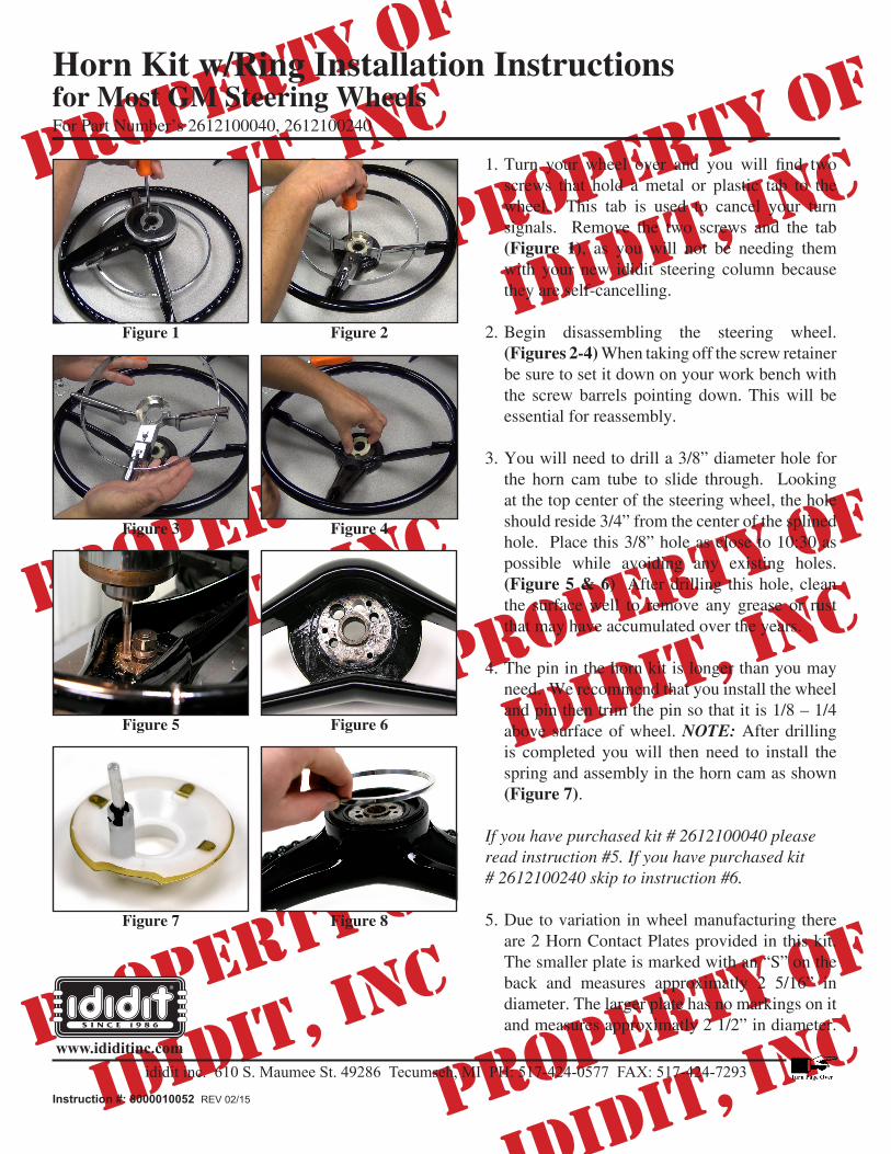
1.Turn your wheel over and you will find twoscrews that hold a metal or plastic tab to the wheel. This tab is used to cancel your turn signals. Remove the two screws and the tab (Figure 1), as you will not be needing them with your new ididit steering column because they are self-cancelling.
2. Begin disassembling the steering wheel. (Figures 2-4) When taking off the screw retainer be sure to set it down on your work bench with the screw barrels pointing down. This will be essential for reassembly.
3. You will need to drill a 3/8” diameter hole for the horn cam tube to slide through. Looking at the top center of the steering wheel, the hole should reside 3/4” from the center of the splined hole. Place this 3/8” hole as close to 10:30 as possible while avoiding any existing holes. (Figure 5 & 6) After drilling this hole, clean the surface well to remove any grease or rust that may have accumulated over the years.
4. The pin in the horn kit is longer than you may need. We recommend that you install the wheel and pin then trim the pin so that it is 1/8 – 1/4 above surface of wheel. NOTE: After drilling is completed you will then need to install the spring and assembly in the horn cam as shown (Figure 7).
If you have purchased kit # 2612100040 please read instruction #5. If you have purchased kit # 2612100240 skip to instruction #6.
5. Due to variation in wheel manufacturing there are 2 Horn Contact Plates provided in this kit. The smaller plate is marked with an “S” on the back and measures approximatly 2 5/16” in diameter. The larger plate has no markings on it and measures approximatly 2 1/2” in diameter.
PROPERTY OF
ididiT, inc
PROPERTY OF
ididiT, inc
PROPERTY OF
ididiT, inc
PROPERTY OF
ididiT, inc
PROPERTY OF
ididiT, inc
PROPERTY OF
ididiT, incididit inc. 610 S. Maumee St. 49286 Tecumseh, MI PH: 517-424-0577 FAX: 517-424-7293
S I N C E 1 9 8 6
www.ididitinc.com
Horn Kit w/Ring Installation Instructions for Most GM Steering WheelsFor Part Number’s 2612100040, 2612100240
Instruction #: 8000010052 REV 02/15
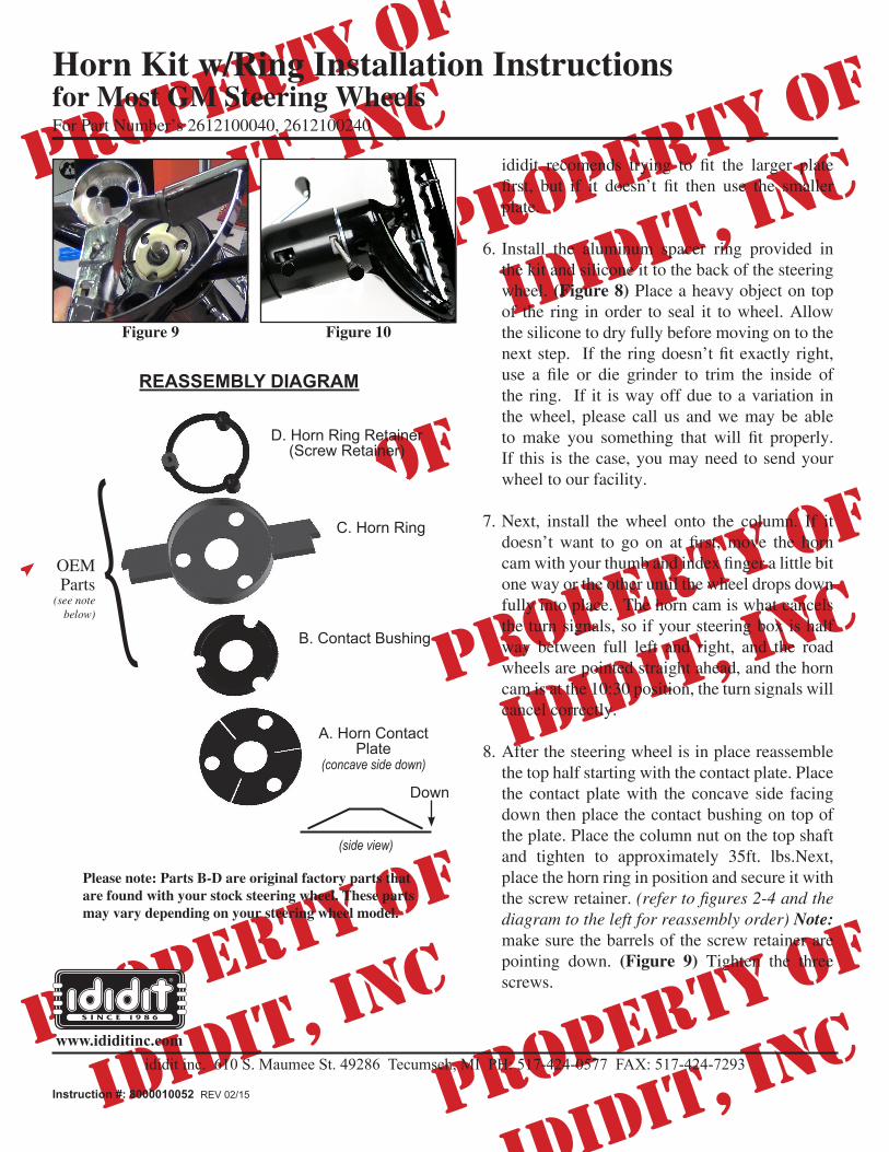
Figure 9 Figure 10
ididit recomends trying to fit the larger platefirst, but if it doesn’t fit then use the smallerplate.
6. Install the aluminum spacer ring provided in the kit and silicone it to the back of the steering wheel. (Figure 8) Place a heavy object on top of the ring in order to seal it to wheel. Allow the silicone to dry fully before moving on to the nextstep. If theringdoesn’tfitexactlyright,use a file or die grinder to trim the inside ofthe ring. If it is way off due to a variation in the wheel, please call us and we may be able tomake you something that will fit properly.If this is the case, you may need to send your wheel to our facility.
7. Next, install the wheel onto the column. If it doesn’twant to go on at first,move the horncamwithyourthumbandindexfingeralittlebitone way or the other until the wheel drops down fully into place. The horn cam is what cancels the turn signals, so if your steering box is half way between full left and right, and the road wheels are pointed straight ahead, and the horn cam is at the 10:30 position, the turn signals will cancel correctly.
8. After the steering wheel is in place reassemble the top half starting with the contact plate. Place the contact plate with the concave side facing down then place the contact bushing on top of the plate. Place the column nut on the top shaft and tighten to approximately 35ft. lbs.Next, place the horn ring in position and secure it with the screw retainer. (refer to figures 2-4 and the diagram to the left for reassembly order) Note: make sure the barrels of the screw retainer are pointing down. (Figure 9) Tighten the three screws.
REASSEMBLY DIAGRAM
D. Horn Ring Retainer (Screw Retainer)
C. Horn Ring
B. Contact Bushing
A. Horn Contact Plate
(concave side down)
Down
(side view)
Please note: Parts B-D are original factory parts that are found with your stock steering wheel. These parts may vary depending on your steering wheel model.
{OEM Parts
(see note below)