Embed Size (px)
Citation preview
Les documents de présession du Comité exécutif du Fonds multilatéral aux fins d’application du Protocole de Montréal sont présentés sous réserve des décisions pouvant être prises par le Comité exécutif après leur publication.
NATIONS UNIES EP
Programme des Nations Unies pour l'environnement
Distr. GENERALE UNEP/OzL.Pro/ExCom/65/53 18 octobre 2011 FRANÇAIS ORIGINAL : ANGLAIS
COMITE EXECUTIF DU FONDS MULTILATERAL AUX FINS D’APPLICATION DU PROTOCOLE DE MONTREAL Soixante-cinquième réunion Bali, Indonésie, 13 – 17 novembre 2011
COUTS DIFFERENTIELS DE LA MODERNISATION DE L’EQUIPEMENT NECESSAIRE A LA FABRICATION DES ECHANGEURS DE CHALEUR
(DECISIONS 61/45 ET 62/61)
UNEP/OzL.Pro/ExCom/65/53
2
1. Lors de la préparation de la 59e réunion du Comité exécutif, le Secrétariat avait soulevé la question des coûts de la reconversion de la fabrication des composants par rapport aux coûts différentiels d’exploitation. Par sa décision 59/14, le Comité exécutif avait décidé de renvoyer l'examen de cette question à sa 60e réunion, puis à sa 61e réunion par sa décision 60/45. À la 61e réunion, les questions soulevées dans le document correspondant UNEP/OzL.Pro/ExCom/61/51 ont été examinées et résolues, à l’exception de la question du financement de la conversion de la fabrication des échangeurs de chaleur.
2. Le Comité exécutif a pris la décision 61/45(c) demandant au Secrétariat de préparer un document sur le niveau des coûts différentiels liés à la reconversion de la fabrication des échangeurs à tube à ailettes en vue de son examen par le Comité exécutif à la 62e réunion. Le Secrétariat a préparé le document UNEP/OzL.Pro/ExCom/62/55 qui figure à l’annexe I au présent document. Au cours des délibérations du Comité exécutif, la qualité du document a été mise en doute car, de l’opinion d’un délégué, il ne tenait pas suffisamment compte des questions très techniques qui sont en jeu. Le Comité exécutif a pris la décision 62/61 pour demander au Secrétariat du fonds de préparer un nouveau document sur les coûts différentiels de la reconversion de la fabrication des échangeurs de chaleur afin d’aider aux délibérations du Comité, en y intégrant tout point de vue qu’il pourrait recevoir de la part d’experts, d’agences d’exécution et de membres du Comité exécutif. Le présent document fait suite à la décision 62/61 et tient compte des questions très techniques soulevées.
Approche 3. Le Secrétariat a analysé les délibérations lors de la 62e réunion et transcrit les portions d’une intervention d’un membre du Comité exécutif qui se rapportaient aux questions techniques, fournissant des précisions pour une recherche sur des sujets particuliers. Le Secrétariat a également reçu une lettre du département de la recherche et du développement de Petra Engineering Industries Co., (Jordanie), qui bénéficie d’un projet de démonstration de conversion de la fabrication de climatiseurs à la technologie HFC-410A, pour lequel une décision de financement de la conversion des échangeurs de chaleur est en souffrance. Les informations correspondantes figurent dans les pièces jointes I et II, respectivement. Le Secrétariat à également examiné avec les agences d’exécution cette même question, en particulier avec le PNUD, lors de l’examen des projets de conversion dans le cadre du PGEH de l’Indonésie. Le Secrétariat a analysé les contributions correspondantes, il a préparé une liste des questions techniques à examiner et il est arrivé à la conclusion que les travaux s’y rapportant doivent être menés par un expert externe. Le Secrétariat a sélectionné un expert qui convenait et l’a recruté pour effectuer une étude. L’expert, qui avait pris sa retraite plus tôt cette année, est membre du Comité des choix techniques pour la réfrigération et avait été auparavant le responsable technique du développement des refroidisseurs et le chef de la technologie et du développement des compresseurs dans une grande compagnie de fabrication d’équipement de climatisation. L’étude figure dans la pièce jointe I du présent document.
4. L’étude technique est axée sur la pratique dans l’industrie de fabrication de climatiseurs durant la conversion du HCFC-22 au HFC-410A. Certains aspects méritent d’être soulignés ici :
(a) L’expert indique que la pression du système et l’augmentation nécessaire de l’épaisseur des parois des tubes sont liées aux températures potentiellement élevées, à la pression correspondante ressentie pendant le transport, c’est-à-dire indépendamment du climat sur le site d’utilisation du produit, et à une pression plus élevée que celle ressentie pendant le fonctionnement;
(b) L’expert fait également valoir que la résistance à la pression est en tout état de cause un multiple de la pression probable la plus élevée, définie en fonction des températures décrites à l’alinéa a);
UNEP/OzL.Pro/ExCom/65/53
3
(c) Il précise également que face aux défis de la conversion du HCFC-22 au HFC-410A, l’industrie a modifié la procédure afin d’assurer une résistance à la pression, passant d’une approche statique qui prévoit cinq fois la pression maximum, à une approche dynamique plus complexe, plus proche de la réalité, où les essais de pression sont limités à trois fois la pression probable la plus élevée, mais le système devra résister d’abord aux 200 000 cycles de la pression probable la plus élevée appliquée puis relâchée de nouveau. L’expert explique que ce processus exerce une pression supplémentaire importante sur l’équipement, ce qui fait ressortir des faiblesses qui n’étaient pas visibles avec les épreuves statiques, bien que la pression la plus élevée de l’épreuve dynamique soit inférieure à celle de l’épreuve statique; et
(d) En conséquence, les climatiseurs en général, et les échangeurs de chaleur en particulier, possèdent des caractéristiques au moins aussi bonnes, et peut-être même meilleures, ce qui implique des modifications mineures dans la conception, mais aucune une modification importante dans la conversion.
5. Le consultant a également quantifié les coûts possibles liés aux épreuves dynamiques ainsi que les outils supplémentaires nécessaires pour assurer la qualité suffisante du produit. L’étude explique aussi en détail un certain nombre de changements types dans la conception, explications qui reposent sur des expériences pratiques durement acquises et qui pourraient donc guider les agences d’exécution et les entreprises en matière de reconception, lorsqu’une conversion a lieu. Le Secrétariat estime que l’étude, directement ou indirectement, a couvert toutes les questions techniques soulevées dans les délibérations du Comité exécutif ou avec le Secrétariat.
6. Le Tableau 1 ci-dessous montre les coûts différentiels estimés pour la conversion des échangeurs de chaleur.
Tableau 1 : Coûts de la conversion des échangeurs de chaleur
Élément du coût Coût pour les compagnies
moyennes ($ US) Coût pour les grandes
compagnies ($ US)
Outils 15 000 15 000
Outillage d’épreuve 100 000 Dépend du cas particulier
Contingence 11 500 Dépend du cas particulier
Total (par compagnie) 126 500 ≥15 000 7. Le Secrétariat a examiné avec le consultant les conclusions possibles que l’on pouvait tirer de l’étude pour ce qui était de l’appui nécessaire aux fabricants dans les pays visés par l’article 5. Il en est ressorti que les conversions au HFC-410A exigent généralement de l'ingénierie, non pas en raison de besoin de la conversion de la fabrication, mais pour adopter de petites modifications de conception afin de permettre les différents comportements dynamiques du réfrigérant dans le cycle; ne pas introduire ces modifications semble être souvent la cause de vibrations conduisant à la rupture des joints, etc. Comme les joints ne sont pas particulièrement nombreux dans les échangeurs de chaleur et leur environnement, l’épreuve dynamique garantit la résistance des échangeurs de chaleur ainsi que la qualité d’ensemble de la fabrication.
8. Le consultant était d’avis que les fabricants de taille moyenne, comme Petra Engineering Industries Co., pouvaient procéder eux-mêmes aux épreuves dynamiques. Ces fabricants de taille moyenne sont ceux qui ont une consommation dépassant les 100 tonnes métriques de HCFC-22 et des groupes distincts de certification interne et de contrôle de la qualité. Pour les petits fabricants, il serait plus avisé de créer un centre de compétences dans le pays et de permettre aux compagnies d’accéder au savoir-faire de ce centre et pour y réaliser les épreuves. Le consultant a considéré que cette approche
UNEP/OzL.Pro/ExCom/65/53
4
centralisée était plus efficace en raison des compétences nécessaires à la conduite des épreuves. Les petits fabricants n’ont tout simplement pas besoin d’effectuer toutes les épreuves pour justifier d’un équipement spécialisé ou de réaliser suffisamment d’épreuves pour développer leur propre savoir-faire. Le consultant recommandait donc, dans les cas où les fabricants produisaient leurs propres échangeurs de chaleur, d’appuyer les grands fabricants et les fabricants de taille moyenne avec de l’outillage d’épreuve et un financement limité pour améliorer les outils de fabrication. Les pays ayant un grand nombre de petites compagnies recevront un financement pour mettre sur pied un centre spécialisé d’épreuves ainsi qu’un appui en matière d’outillage pour les petits fabricants, et les petites compagnies sans accès à un centre spécialisé d’épreuves, bénéficieraient d’un financement pour acheter de petits appareils d’épreuves pour tester l’équipement au mieux de leurs compétences.
9. Le consultant a souligné que la fabrication d’un volume élevé d’un seul modèle d’échangeur de chaleur pourrait avoir différents besoins en matière d’outillage, selon la souplesse exacte, ou le manque de souplesse, de l’outillage utilisé dans le processus. Cela n’a pas pu être évalué dans l’étude, étant donné que cela dépend beaucoup de l’installation donnée. Cependant, il semble que le seul cas où le volume élevé de fabrication pourrait poser un problème en matière d’installations qui ne soit pas la propriété de multinationales serait celui de quelques fabricants en Chine, pour lesquels le niveau de financement jusqu’en 2015 a déjà été approuvé. En conséquence, il n’y a pas de besoin immédiat sur cette question particulière.
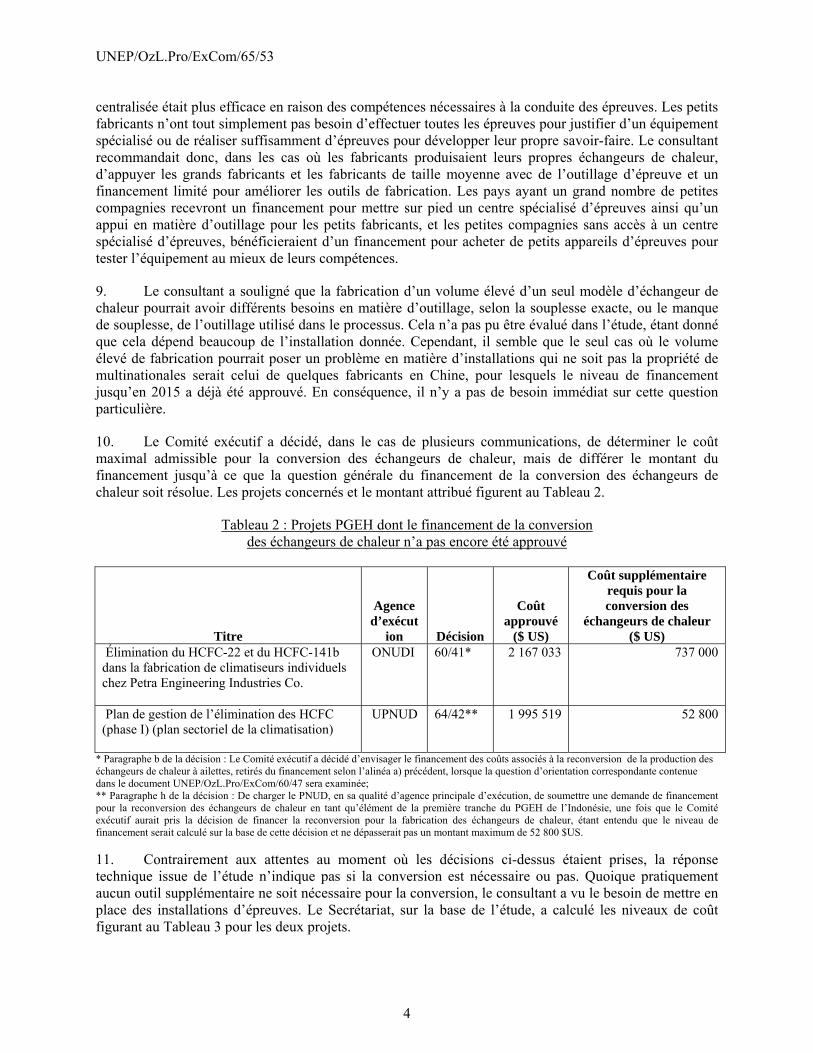
10. Le Comité exécutif a décidé, dans le cas de plusieurs communications, de déterminer le coût maximal admissible pour la conversion des échangeurs de chaleur, mais de différer le montant du financement jusqu’à ce que la question générale du financement de la conversion des échangeurs de chaleur soit résolue. Les projets concernés et le montant attribué figurent au Tableau 2.
Tableau 2 : Projets PGEH dont le financement de la conversion des échangeurs de chaleur n’a pas encore été approuvé
Titre
Agence d’exécut
ion Décision
Coût approuvé
($ US)
Coût supplémentaire requis pour la conversion des
échangeurs de chaleur ($ US)
Élimination du HCFC-22 et du HCFC-141b dans la fabrication de climatiseurs individuels chez Petra Engineering Industries Co.
ONUDI 60/41* 2 167 033 737 000
Plan de gestion de l’élimination des HCFC (phase I) (plan sectoriel de la climatisation)
UPNUD 64/42** 1 995 519 52 800
* Paragraphe b de la décision : Le Comité exécutif a décidé d’envisager le financement des coûts associés à la reconversion de la production des échangeurs de chaleur à ailettes, retirés du financement selon l’alinéa a) précédent, lorsque la question d’orientation correspondante contenue dans le document UNEP/OzL.Pro/ExCom/60/47 sera examinée; ** Paragraphe h de la décision : De charger le PNUD, en sa qualité d’agence principale d’exécution, de soumettre une demande de financement pour la reconversion des échangeurs de chaleur en tant qu’élément de la première tranche du PGEH de l’Indonésie, une fois que le Comité exécutif aurait pris la décision de financer la reconversion pour la fabrication des échangeurs de chaleur, étant entendu que le niveau de financement serait calculé sur la base de cette décision et ne dépasserait pas un montant maximum de 52 800 $US.
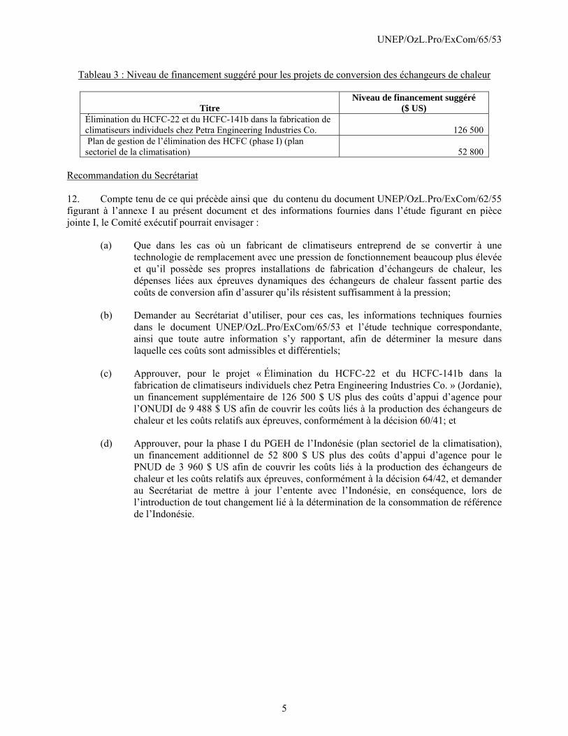
11. Contrairement aux attentes au moment où les décisions ci-dessus étaient prises, la réponse technique issue de l’étude n’indique pas si la conversion est nécessaire ou pas. Quoique pratiquement aucun outil supplémentaire ne soit nécessaire pour la conversion, le consultant a vu le besoin de mettre en place des installations d’épreuves. Le Secrétariat, sur la base de l’étude, a calculé les niveaux de coût figurant au Tableau 3 pour les deux projets.
UNEP/OzL.Pro/ExCom/65/53
5
Tableau 3 : Niveau de financement suggéré pour les projets de conversion des échangeurs de chaleur
Titre Niveau de financement suggéré
($ US) Élimination du HCFC-22 et du HCFC-141b dans la fabrication de climatiseurs individuels chez Petra Engineering Industries Co. 126 500 Plan de gestion de l’élimination des HCFC (phase I) (plan sectoriel de la climatisation) 52 800
Recommandation du Secrétariat 12. Compte tenu de ce qui précède ainsi que du contenu du document UNEP/OzL.Pro/ExCom/62/55 figurant à l’annexe I au présent document et des informations fournies dans l’étude figurant en pièce jointe I, le Comité exécutif pourrait envisager :
(a) Que dans les cas où un fabricant de climatiseurs entreprend de se convertir à une technologie de remplacement avec une pression de fonctionnement beaucoup plus élevée et qu’il possède ses propres installations de fabrication d’échangeurs de chaleur, les dépenses liées aux épreuves dynamiques des échangeurs de chaleur fassent partie des coûts de conversion afin d’assurer qu’ils résistent suffisamment à la pression;
(b) Demander au Secrétariat d’utiliser, pour ces cas, les informations techniques fournies dans le document UNEP/OzL.Pro/ExCom/65/53 et l’étude technique correspondante, ainsi que toute autre information s’y rapportant, afin de déterminer la mesure dans laquelle ces coûts sont admissibles et différentiels;
(c) Approuver, pour le projet « Élimination du HCFC-22 et du HCFC-141b dans la fabrication de climatiseurs individuels chez Petra Engineering Industries Co. » (Jordanie), un financement supplémentaire de 126 500 $ US plus des coûts d’appui d’agence pour l’ONUDI de 9 488 $ US afin de couvrir les coûts liés à la production des échangeurs de chaleur et les coûts relatifs aux épreuves, conformément à la décision 60/41; et
(d) Approuver, pour la phase I du PGEH de l’Indonésie (plan sectoriel de la climatisation), un financement additionnel de 52 800 $ US plus des coûts d’appui d’agence pour le PNUD de 3 960 $ US afin de couvrir les coûts liés à la production des échangeurs de chaleur et les coûts relatifs aux épreuves, conformément à la décision 64/42, et demander au Secrétariat de mettre à jour l’entente avec l’Indonésie, en conséquence, lors de l’introduction de tout changement lié à la détermination de la consommation de référence de l’Indonésie.
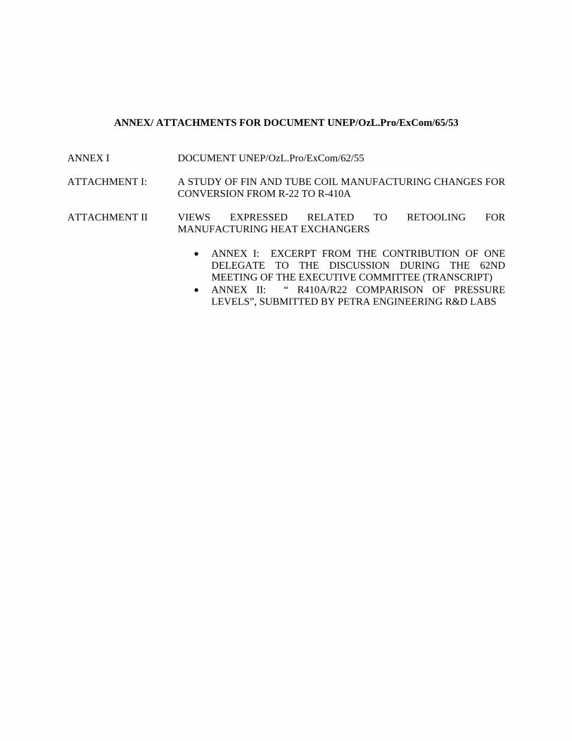
ANNEX/ ATTACHMENTS FOR DOCUMENT UNEP/OzL.Pro/ExCom/65/53 ANNEX I DOCUMENT UNEP/OzL.Pro/ExCom/62/55
ATTACHMENT I: A STUDY OF FIN AND TUBE COIL MANUFACTURING CHANGES FOR
CONVERSION FROM R-22 TO R-410A
ATTACHMENT II VIEWS EXPRESSED RELATED TO RETOOLING FOR MANUFACTURING HEAT EXCHANGERS
• ANNEX I: EXCERPT FROM THE CONTRIBUTION OF ONE DELEGATE TO THE DISCUSSION DURING THE 62ND MEETING OF THE EXECUTIVE COMMITTEE (TRANSCRIPT)
• ANNEX II: “ R410A/R22 COMPARISON OF PRESSURE LEVELS”, SUBMITTED BY PETRA ENGINEERING R&D LABS
Les documents de présession du Comité exécutif du Fonds multilatéral aux fins d’application du Protocole de
Montréal sont présentés sous réserve des décisions pouvant être prises par le Comité exécutif après leur publication.
NATIONS UNIES EP
Programme des Nations Unies pour l'environnement
Distr.
GENERALE
UNEP/OzL.Pro/ExCom/62/55
29 octobre 2010
FRANÇAIS
ORIGINAL : ANGLAIS
COMITE EXECUTIF
DU FONDS MULTILATERAL AUX FINS
D’APPLICATION DU PROTOCOLE DE MONTREAL
Soixante-deuxième réunion
Montréal, 29 novembre – 3 décembre 2010
SURCOÛTS LIÉS À LA RECONVERSION DE LA FABRICATION
D’ÉCHANGEURS DE CHALEUR (DÉCISION 61/45)
UNEP/OzL.Pro/ExCom/62/55
2
1. Lors de la préparation de la 59e réunion du Comité exécutif, le Secrétariat avait soulevé la
question des coûts de la reconversion de la fabrication des composants par rapport aux coûts différentiels
d’exploitation. Par sa décision 59/14, le Comité exécutif avait décidé de renvoyer l'examen de cette
question à sa 60e réunion, puis à sa 61
e réunion par sa décision 60/45.
2. À la 61e réunion, les questions soulevées dans le document UNEP/OzL.Pro/ExCom/61/51 ont été
examinées et résolues, à l’exception de la question du financement de la reconversion de la fabrication
d’échangeurs de chaleur. Le Comité exécutif a donc décidé, dans sa décision 61/45 c), de demander au
Secrétariat de s’inspirer des sections pertinentes du document UNEP/OzL.Pro/ExCom/61/51 pour
préparer à son intention un document sur le niveau des surcoûts liés à la reconversion de la fabrication
d’échangeurs de chaleur à tubes à ailettes, qu’il examinera à sa 62e réunion.
Surcoûts des échangeurs de chaleur
3. Durant son examen des projets soumis, le Secrétariat a dégagé la question de savoir s’il convenait
de considérer la reconversion de la production d’échangeurs de chaleur comme un surcoût. Les
paragraphes qui suivent tenteront d’expliquer les aspects extrêmement techniques de la question, afin de
permettre au Comité exécutif de prendre une décision éclairée en la matière.
4. La production d’échangeurs de chaleur mentionnée dans le présent document est liée à la
production d’échangeurs de chaleur frigorigène-air. Ces dispositifs comprennent normalement des tubes
de cuivre portant des ailettes perpendiculaires en aluminium.
5. Les ailettes sont fabriquées au moyen de matrices complexes dans lesquelles elles sont perforées
et formées par passages multiples. Le diamètre extérieur des tubes est légèrement inférieur au diamètre
des perforations des ailettes, ce qui en facilite l’alignement sur l’ensemble de tubes. Normalement, les
tubes sont dégauchis d’avance et recourbés en u (en « épingle à cheveux »), de façon que chaque tube
traverse deux fois l’échangeur de chaleur, un échangeur pouvant recevoir plusieurs tubes. Les tubes sont
enchevêtrés dans un ensemble d’ailettes (jusqu’à plusieurs centaines) sur une table horizontale. Une fois
ces tubes courbés placés dans la pile d’ailettes, une tige comportant une tête de précision aux dimensions
légèrement supérieures au diamètre intérieur des tubes est poussée dans chaque tube, l’élargissant de
l’intérieur et agrandissant ainsi son diamètre extérieur, pour permettre l’enchâssement des ailettes. En
production à haute vitesse, tous les tubes sont expansés simultanément. En production à très faible
volume, les tubes sont parfois expansés individuellement. Ces échangeurs de chaleur sont appelés des
échangeurs de chaleur à tubes à ailettes.
6. Dans les systèmes de réfrigération et de climatisation, les échangeurs de chaleur frigorigène-air
sont très communs, notamment dans les systèmes produits à grande échelle. Dans les cas de production
de masse, les échangeurs de chaleur sont soit optimisés pour chaque modèle et achetés d’un fournisseur
extérieur, ou, plus fréquemment, optimisés pour une série de modèles du manufacturier et fabriqués sur
place. Normalement, les unités présentant une vaste gamme de capacités sont dotées de tubes au même
diamètre extérieur. Ces échangeurs de chaleur ne diffèrent pas énormément dans leur dessin ou leurs
matériaux, qu’ils relèvent de la technologie HCFC-22 ou de diverses autres technologies HCFC-22 de
rechange disponibles (sauf pour l’ammoniac et le CO2).
7. D’après les experts techniques que le Secrétariat a consultés, il n’est pas nécessaire, du point de
vue des performances du système, de réduire le diamètre des tubes lorsque l’on passe du HCFC-22 au
HFC-410A ou au HFC-32; il en est de même pour la transition au HFC-407C et aux hydrocarbures
HC-290 et HC-1270. Par contre, un léger ajustement dans l’épaisseur des parois des tubes est requis pour
UNEP/OzL.Pro/ExCom/62/55
3
en renforcer la résistance aux pressions plus élevées de l’utilisation du HFC-410A ou du HFC-32. Cette
méthode nécessite beaucoup moins de dépenses d’investissement en équipement, ce qui en fait le premier
choix des manufacturiers pour la reconversion initiale. Une autre solution consiste à utiliser des types
particuliers de cuivre, plus coûteux, qui sont plus résistants à la pression pour des tubes de mêmes
dimensions, ou encore une combinaison des deux méthodes. Une réduction du diamètre extérieur des
tubes, demandée dans certaines propositions de projets, permet de tirer parti de certains avantages offerts
par les propriétés du HFC-410A par rapport au HCFC-22, et résulte dans la miniaturisation des systèmes
et la réduction des poids et des coûts. Les économies de coût sont tellement importantes que même des
échangeurs de chaleur de qualité supérieure peuvent être produits à des coûts d’exploitation sensiblement
inférieurs. Certaines propositions de projets soumises au Secrétariat indiquent des économies
différentielles de plus de 2 USD par kg de HCFC-22.
8. Par contre, comme l’indiquent d’autres propositions de projets, le coût de la reconversion à des
tubes de diamètre extérieur plus faible est très élevé. Les échangeurs de chaleur des systèmes à base de
CO2 doivent normalement utiliser des tubes à faible diamètre en raison des pressions opérationnelles très
élevées des systèmes à CO2 et des différentes capacités par volume. Les systèmes à base de frigorigènes
inflammables (hydrocarbures et, dans une moindre mesure, HFC-152a et HFC-32) peuvent utiliser des
charges de frigorigènes beaucoup plus réduites grâce à des tubes de diamètre inférieur et peuvent donc
être adaptés à l’emploi de frigorigène inflammable sans nécessiter l’addition de nombreuses mesures de
sécurité, comparé aux systèmes à base de HCFC actuels.
9. Les machines de production d’échangeurs de chaleur sont en quelque sorte faites sur mesure,
notamment en ce qui concerne le diamètre extérieur des tubes. Toute modification de ce diamètre
nécessitera le remplacement des équipements, en particulier les matrices des ailettes, les machines à
courber les tubes de cuivre, les machines à braser automatiques et les machines d’expansion des tubes.
Pour la production de produits de consommation (climatiseurs de pièce, etc.), tout cet équipement est
constitué normalement de machines de précision entièrement automatiques, dont les coûts de
modification ou de remplacement sont relativement élevés. Les produits commerciaux ou industriels sont
souvent fabriqués avec un degré d’automatisation moindre, pour permettre des adaptations précises sur
mesure. Le matériel dans ce cas est néanmoins composé de machines de haute précision.
10. Les entreprises tendent actuellement à fabriquer leurs propres échangeurs de chaleur à l’interne,
ce qui leur offre plus de flexibilité dans la conception et la fabrication des systèmes de climatisation de
grandes dimensions, selon les spécifications des clients, et par la même occasion de réaliser des
économies dans les coûts d’exploitation. Dans presque tous les cas soumis à l’attention du Secrétariat, les
fabricants de systèmes de réfrigération et de climatisation produisent leurs propres échangeurs de chaleur
à l’interne.
11. À la suite de la 61e réunion, le Secrétariat a poursuivi ses entretiens avec les agences d’exécution,
ainsi qu’avec les représentants de l’industrie, dans le cadre d’une mission en Chine. Le concept présenté
dans la note du Secrétariat a été expliqué à plusieurs reprises. Une agence en particulier a mentionné la
possibilité d’améliorer le rendement énergétique des climatiseurs en en révisant les dessins et en
optimisant les échangeurs de chaleur. Des représentants de l’industrie ont cité des exemples d’entreprises
homologues qui ont effectué des reconversions, notamment au HFC-410A, en modifiant les échangeurs
de chaleur et qui considéraient la reconversion de la production d’échangeurs de chaleur comme
intrinsèquement liée à la reconversion de la chaîne de production.
12. Durant ces entretiens, le Secrétariat a cité en particulier la décision 61/44 du Comité exécutif, qui
demandait au Secrétariat de maintenir la pratique établie lorsqu’il évalue les mesures d’amélioration des
composants dans les projets de reconversion au HCFC dans les secteurs de la réfrigération et de la
climatisation, de manière qu’après la reconversion, les caractéristiques déterminantes des composants
UNEP/OzL.Pro/ExCom/62/55
4
restent plus ou moins inchangées ou, s’il n’ya pas de composants similaires, que les composants en place
ne soient améliorés que dans la mesure nécessaire pour permettre la reconversion. Le Secrétariat ne s’est
pas demandé si la reconversion de la production d’échangeurs de chaleur serait intrinsèquement liée à la
reconversion au frigorigène, mais il a plutôt mis en doute la nécessité pour le Fonds multilatéral
d’appuyer financièrement la reconversion, étant donné l’absence de besoin technique et la possibilité
d’avantages opérationnels additionnels. Le Secrétariat n’a pas contesté la teneur technique des arguments
présentés par une agence d’exécution concernant le rendement énergétique, et il a simplement souligné
que les activités dont le seul objet est d’améliorer le rendement énergétique ne sont pas admissibles au
titre du Fonds multilatéral. Une entreprise bénéficiaire qui voudrait reconvertir l’usine pour avoir un
meilleur rendement énergétique devra trouver un financement de contrepartie ou un cofinancement.
13. Il a été proposé à tous les acteurs intéressés qui ont entamé des débats sur ce point avec le
Secrétariat de soumettre par écrit toute raison technique justifiant la modification du diamètre extérieur
des tubes, à l’exception des raisons liées à l’amélioration du rendement énergétique ou des coûts. Malgré
des dates limites clairement indiquées et, dans un cas, l’envoi d’un rappel, le Secrétariat n’a reçu aucune
contribution sur ce point.
Recommandation du Secrétariat
14. Compte tenu des discussions dont il est rendu compte précédemment, et de la décision 61/45, le
Secrétariat propose au Comité exécutif la même recommandation que celle qui a été présentée à la
61e réunion dans le document UNEP/OzL.Pro/ExCom/61/51, à savoir que le Comité exécutif est invité,
dans le cas d’une reconversion de systèmes de réfrigération ou de climatisation des HCFC à des HFC non
inflammables, à ne pas traiter comme des surcoûts les coûts en capital liés à la reconversion en vue d’un
changement du diamètre des tubes dans les échangeurs de chaleur à tubes à ailettes, puisqu’un tel
changement est considéré comme une mise à niveau technologique non nécessaire.
_ _ _ _
ATTACHMENT I
A STUDY OF FIN AND TUBE COIL MANUFACTURING CHANGES FOR CONVERSION FROM R-22 TO R-410A
A STUDY OF FIN AND TUBE COIL MANUFACTURING CHANGES FOR CONVERSION FROM R-22 TO R-410A
Dennis Dorman
10/14/2011
Contract No: 1602 October 14, 2011
A STUDY OF FIN AND TUBE COIL MANUFACTURING CHANGES FOR
CONVERSION FROM R-22 TO R-410A
Summary
The Multilateral Fund for the Implementation of the Montreal Protocol (MLF) supports the conversion of manufacturing facilities in developing countries that use ozone‐depleting substances. A study was performed to determine the potential manufacturing cost changes for conversion from refrigerant R‐22 to R‐410A for fin and tube coils used in residential and unitary air conditioning products. Fin and tube coils are the dominant type of air‐to‐refrigerant heat exchanger used for evaporators and condensers of air conditioning equipment. R‐22 was the refrigerant of choice for residential and small unitary air conditioning systems before its phase out in developed countries in 2010. R‐410a is the current refrigerant of choice therefore a good candidate for conversion of products manufactured in developing countries. Since R‐410A has different thermodynamic and physical properties, one might expect significant changes in heat transfer performance and the ability to retain pressure, especially in hot climates. It follows that coil design changes would be necessary and be accompanied by changes in manufacturing processes, capital equipment and tooling. However, the experience of major manufacturers in the period leading up to the 2010 phase out of R‐22 is quite the opposite. The evaporator and condenser coils change very little and then only in regards to smaller features necessary to accommodate fatigue strength considerations. Therefore, major capital equipment purchase should be unnecessary. Some tooling cost may be necessary to manufacture the feature changes resulting from fatigue considerations while insuring robust manufacturing processes, but this should be small. Of special note is the need for manufacturers of coils to be able to rapidly run fatigue tests on coil features. A fatigue test facility is a non‐trivial capital expense that must be borne by the manufacturer, or provided by an institution or private service provider that could provide the fatigue test service economically to several manufacturers on demand.
1. Introduction
The Multilateral Fund for the Implementation of the Montreal Protocol (MLF) supports the conversion of manufacturing facilities in developing countries that use ozone‐depleting substances. The MLF has asked for a study of the manufacturing cost changes that are necessary to change from R‐22 to R‐410A for fin and tube coils that are used in smaller air conditioning products, namely 2 to 5 kW residential room air conditioners (mini‐splits) and 30 to 1000 kW unitary products. In order to determine the design changes associated with a refrigerant conversion, the refrigerant properties differences must first be considered.
Since R‐22 and R‐410A have significantly different thermodynamic and physical properties, one might expect significant changes in coil design. It follows that manufacturing processes, capital equipment and tooling may need to be replaced or changed. This study will examine the two basic aspects of the design
Contract No: 1602 October 14, 2011
problem, namely heat transfer and the ability to retain pressure especially under the extreme conditions that are prevalent in hot, arid climates. Manufacturing changes will be noted and their costs estimated.
2. Baseline Coil Information
The following represent the typical base line coils or design standard that were used in products before conversion to R‐410A. The term “design standard” means that most manufacturers would use coil design that are very similar though not identical. For example, the actual configuration of the aluminum fin may be different between manufacturers. The standards described below have been the used for more than 20 years. Enhancements to standard design occur as engineering and manufacturing technologies improve. Enhancements are usually aimed at improving performance and decreasing size and cost. These design standards are key to hitting ever increasing energy standards, maintaining a physically small product, and removing material cost – in other words, being competitive in the market place. The design standard is supported by raw material suppliers of fin stock, coil tubing, U‐bends, etc., and are widely available from multiple suppliers. Companies that currently do not follow these design standards will be uncompetitive. Coil designs in developing countries may or may not be similar those described notably in the tube diameter which essentially changes all manufacturing tooling. In low volumes, the investment to upgrade typically is a barrier. These manufacturers would require a substantially larger upgrade of their manufacturing facilities than described in this report, leading to substantially higher conversion cost. While this would result in the ability to use R‐410A and have competitive costs, it also represents an opportunity to increase product quality. Further discussion of such an upgrade is beyond the scope of this report
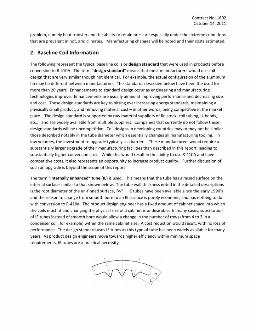
The term “internally enhanced” tube (IE) is used. This means that the tube has a raised surface on the internal surface similar to that shown below. The tube wall thickness noted in the detailed descriptions is the root diameter of the un‐finned surface, “w” . IE tubes have been available since the early 1990’s and the reason to change from smooth bore to an IE surface is purely economic, and has nothing to do with conversion to R‐410a. The product design engineer has a fixed amount of cabinet space into which the coils must fit and changing the physical size of a cabinet is undesirable. In many cases, substitution of IE tubes instead of smooth bore would allow a change in the number of rows (from 4 to 3 in a condenser coil, for example) within the same cabinet size. A cost reduction would result, with no loss of performance. The design standard uses IE tubes as this type of tube has been widely available for many years. As product design engineers move towards higher efficiency within minimum space requirements, IE tubes are a practical necessity.
Contract No: 1602 October 14, 2011
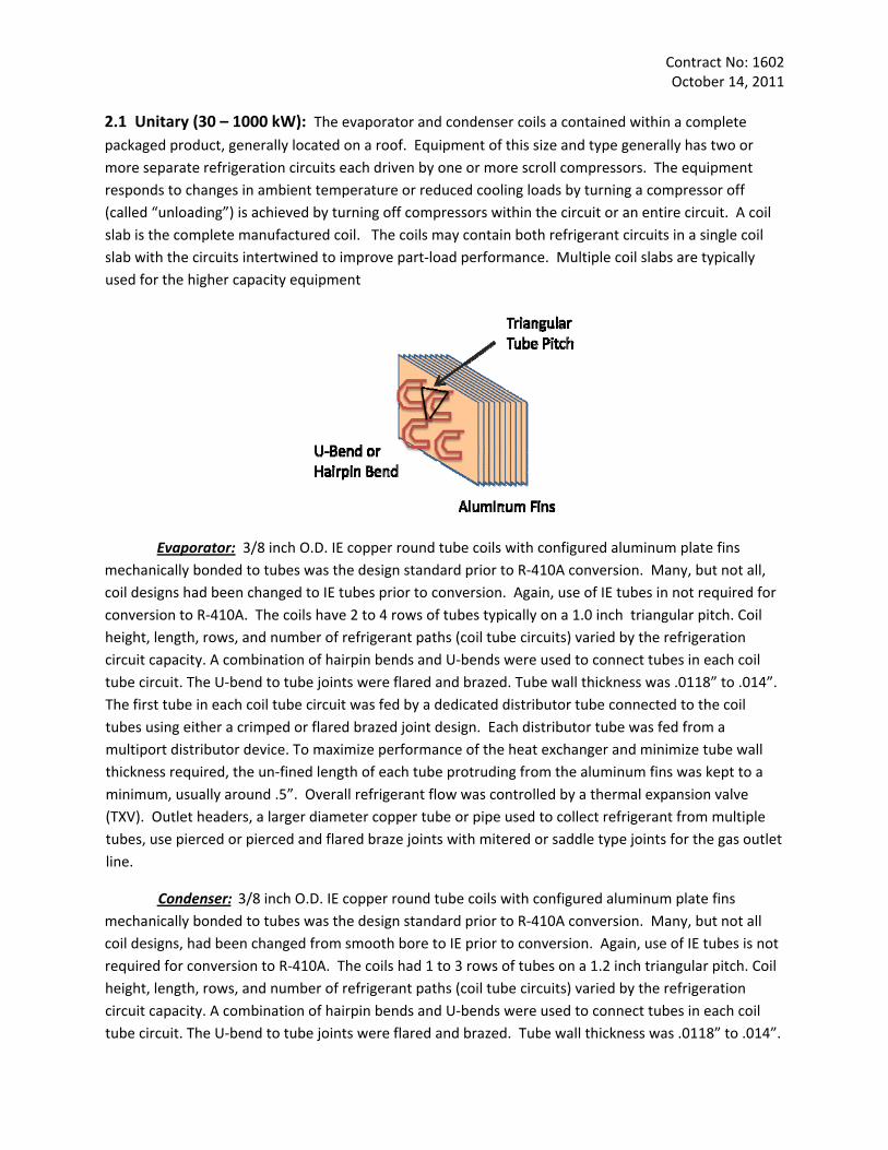
2.1 Unitary (30 – 1000 kW): The evaporator and condenser coils a contained within a complete
packaged product, generally located on a roof. Equipment of this size and type generally has two or more separate refrigeration circuits each driven by one or more scroll compressors. The equipment responds to changes in ambient temperature or reduced cooling loads by turning a compressor off (called “unloading”) is achieved by turning off compressors within the circuit or an entire circuit. A coil slab is the complete manufactured coil. The coils may contain both refrigerant circuits in a single coil slab with the circuits intertwined to improve part‐load performance. Multiple coil slabs are typically used for the higher capacity equipment
Evaporator: 3/8 inch O.D. IE copper round tube coils with configured aluminum plate fins mechanically bonded to tubes was the design standard prior to R‐410A conversion. Many, but not all, coil designs had been changed to IE tubes prior to conversion. Again, use of IE tubes in not required for conversion to R‐410A. The coils have 2 to 4 rows of tubes typically on a 1.0 inch triangular pitch. Coil height, length, rows, and number of refrigerant paths (coil tube circuits) varied by the refrigeration circuit capacity. A combination of hairpin bends and U‐bends were used to connect tubes in each coil tube circuit. The U‐bend to tube joints were flared and brazed. Tube wall thickness was .0118” to .014”. The first tube in each coil tube circuit was fed by a dedicated distributor tube connected to the coil tubes using either a crimped or flared brazed joint design. Each distributor tube was fed from a multiport distributor device. To maximize performance of the heat exchanger and minimize tube wall thickness required, the un‐fined length of each tube protruding from the aluminum fins was kept to a minimum, usually around .5”. Overall refrigerant flow was controlled by a thermal expansion valve (TXV). Outlet headers, a larger diameter copper tube or pipe used to collect refrigerant from multiple tubes, use pierced or pierced and flared braze joints with mitered or saddle type joints for the gas outlet line.
Condenser: 3/8 inch O.D. IE copper round tube coils with configured aluminum plate fins mechanically bonded to tubes was the design standard prior to R‐410A conversion. Many, but not all coil designs, had been changed from smooth bore to IE prior to conversion. Again, use of IE tubes is not required for conversion to R‐410A. The coils had 1 to 3 rows of tubes on a 1.2 inch triangular pitch. Coil height, length, rows, and number of refrigerant paths (coil tube circuits) varied by the refrigeration circuit capacity. A combination of hairpin bends and U‐bends were used to connect tubes in each coil tube circuit. The U‐bend to tube joints were flared and brazed. Tube wall thickness was .0118” to .014”.
Contract No: 1602 October 14, 2011
The first tube in each coil tube circuit was fed from a cylindrical header, and the last tube in each coil circuit was connected to a cylindrical outlet header all made from copper. The diameter of these headers varied by overall refrigeration circuit capacity with the largest outside diameter about 1.625” . To maximize performance of the heat exchanger and minimize tube wall thickness required, the un‐fined length of each tube protruding from the aluminum fins was kept to a minimum, usually around .5”. Both inlet and outlet headers use pierced or pierced and flared braze joints with mitered or saddle type joints for the gas inlet and liquid outlet lines
2.2 Residential (2‐5 kW): Equipment of this size and type generally has a single refrigeration circuit
driven by one non‐unloading (no capacity control) rotary compressor. The evaporator coil is contained with a wall mounted cassette mounted in the air conditioned space, while the condenser coil is located outdoors.
Both the evaporator and condenser coils use 7 mm. O.D. IE copper round tube coils . Fins are highly configured aluminum plate fins mechanically bonded to tubes. The wall thickness is 0.25 mm. Though not the design standard, some manufacturers may have already switched to lower cost aluminum tube or smaller diameter (5 mm. or 6 mm.) before R‐410A conversion. Small product typically has single row coils, whereas larger product uses two row coils. Both evaporator and condenser coils are made using hairpin bend and brazed U bends. In the case of evaporators, a short orifice is used to feed the circuits. Headers are made from small diameter copper tube. All connections are brazed.
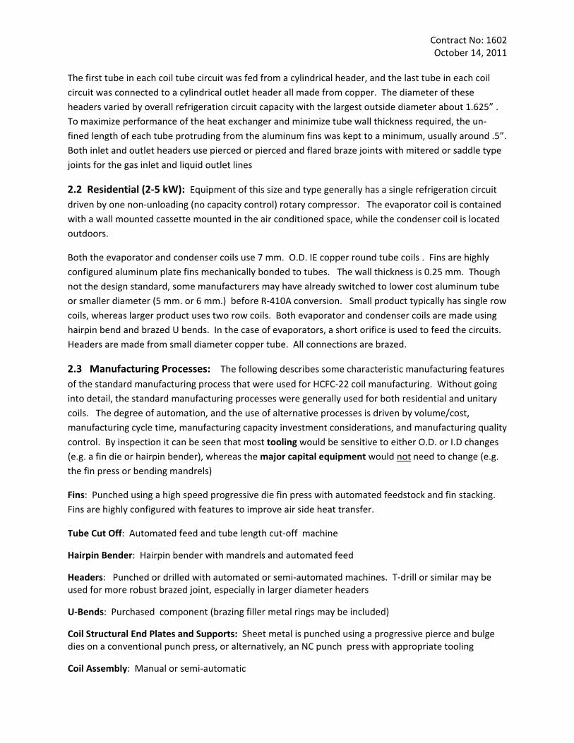
2.3 Manufacturing Processes: The following describes some characteristic manufacturing features
of the standard manufacturing process that were used for HCFC‐22 coil manufacturing. Without going into detail, the standard manufacturing processes were generally used for both residential and unitary coils. The degree of automation, and the use of alternative processes is driven by volume/cost, manufacturing cycle time, manufacturing capacity investment considerations, and manufacturing quality control. By inspection it can be seen that most tooling would be sensitive to either O.D. or I.D changes (e.g. a fin die or hairpin bender), whereas the major capital equipment would not need to change (e.g. the fin press or bending mandrels)
Fins: Punched using a high speed progressive die fin press with automated feedstock and fin stacking. Fins are highly configured with features to improve air side heat transfer.
Tube Cut Off: Automated feed and tube length cut‐off machine
Hairpin Bender: Hairpin bender with mandrels and automated feed
Headers: Punched or drilled with automated or semi‐automated machines. T‐drill or similar may be used for more robust brazed joint, especially in larger diameter headers
U‐Bends: Purchased component (brazing filler metal rings may be included)
Coil Structural End Plates and Supports: Sheet metal is punched using a progressive pierce and bulge dies on a conventional punch press, or alternatively, an NC punch press with appropriate tooling
Coil Assembly: Manual or semi‐automatic
Contract No: 1602 October 14, 2011
Tube Expansion: Ball end multi‐rod expanders or ball expanders driven with hydraulics for low volume coils
Headers, U‐bend or Distributor Tubes: The coil tube is crimped to form a brazing joint for the distributor tube. Brazing is done with a dry nitrogen purge. Single and multi‐tip torches are used.
Pressure and Leak Test: Air under Water immersion in water tank with safety cover
Final Product Pressure and Leak Test: Dry air plus halogen leak detector
Process Fluids: All process fluids used during manufacture and testing of the heat exchangers are selected to be compatible with R‐22 and the refrigeration mineral oil
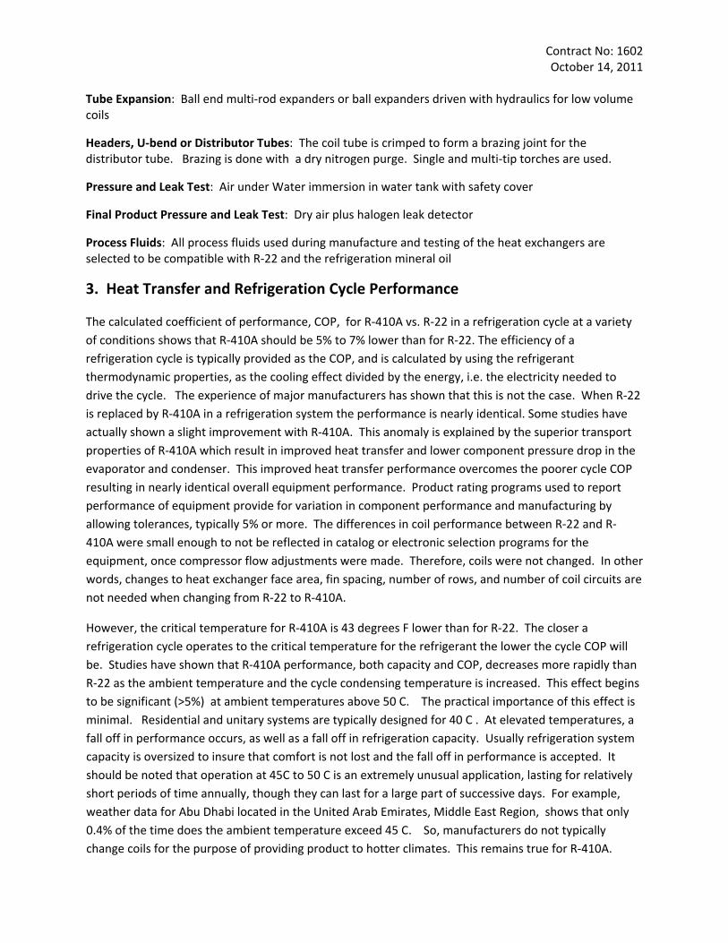
3. Heat Transfer and Refrigeration Cycle Performance
The calculated coefficient of performance, COP, for R‐410A vs. R‐22 in a refrigeration cycle at a variety of conditions shows that R‐410A should be 5% to 7% lower than for R‐22. The efficiency of a refrigeration cycle is typically provided as the COP, and is calculated by using the refrigerant thermodynamic properties, as the cooling effect divided by the energy, i.e. the electricity needed to drive the cycle. The experience of major manufacturers has shown that this is not the case. When R‐22 is replaced by R‐410A in a refrigeration system the performance is nearly identical. Some studies have actually shown a slight improvement with R‐410A. This anomaly is explained by the superior transport properties of R‐410A which result in improved heat transfer and lower component pressure drop in the evaporator and condenser. This improved heat transfer performance overcomes the poorer cycle COP resulting in nearly identical overall equipment performance. Product rating programs used to report performance of equipment provide for variation in component performance and manufacturing by allowing tolerances, typically 5% or more. The differences in coil performance between R‐22 and R‐410A were small enough to not be reflected in catalog or electronic selection programs for the equipment, once compressor flow adjustments were made. Therefore, coils were not changed. In other words, changes to heat exchanger face area, fin spacing, number of rows, and number of coil circuits are not needed when changing from R‐22 to R‐410A.
However, the critical temperature for R‐410A is 43 degrees F lower than for R‐22. The closer a refrigeration cycle operates to the critical temperature for the refrigerant the lower the cycle COP will be. Studies have shown that R‐410A performance, both capacity and COP, decreases more rapidly than R‐22 as the ambient temperature and the cycle condensing temperature is increased. This effect begins to be significant (>5%) at ambient temperatures above 50 C. The practical importance of this effect is minimal. Residential and unitary systems are typically designed for 40 C . At elevated temperatures, a fall off in performance occurs, as well as a fall off in refrigeration capacity. Usually refrigeration system capacity is oversized to insure that comfort is not lost and the fall off in performance is accepted. It should be noted that operation at 45C to 50 C is an extremely unusual application, lasting for relatively short periods of time annually, though they can last for a large part of successive days. For example, weather data for Abu Dhabi located in the United Arab Emirates, Middle East Region, shows that only 0.4% of the time does the ambient temperature exceed 45 C. So, manufacturers do not typically change coils for the purpose of providing product to hotter climates. This remains true for R‐410A.
Contract No: 1602 October 14, 2011
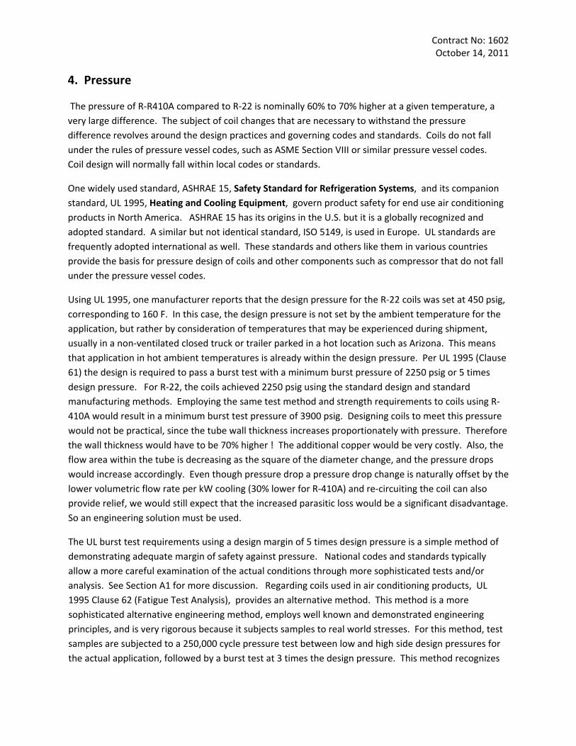
4. Pressure
The pressure of R‐R410A compared to R‐22 is nominally 60% to 70% higher at a given temperature, a very large difference. The subject of coil changes that are necessary to withstand the pressure difference revolves around the design practices and governing codes and standards. Coils do not fall under the rules of pressure vessel codes, such as ASME Section VIII or similar pressure vessel codes. Coil design will normally fall within local codes or standards.
One widely used standard, ASHRAE 15, Safety Standard for Refrigeration Systems, and its companion standard, UL 1995, Heating and Cooling Equipment, govern product safety for end use air conditioning products in North America. ASHRAE 15 has its origins in the U.S. but it is a globally recognized and adopted standard. A similar but not identical standard, ISO 5149, is used in Europe. UL standards are frequently adopted international as well. These standards and others like them in various countries provide the basis for pressure design of coils and other components such as compressor that do not fall under the pressure vessel codes.
Using UL 1995, one manufacturer reports that the design pressure for the R‐22 coils was set at 450 psig, corresponding to 160 F. In this case, the design pressure is not set by the ambient temperature for the application, but rather by consideration of temperatures that may be experienced during shipment, usually in a non‐ventilated closed truck or trailer parked in a hot location such as Arizona. This means that application in hot ambient temperatures is already within the design pressure. Per UL 1995 (Clause 61) the design is required to pass a burst test with a minimum burst pressure of 2250 psig or 5 times design pressure. For R‐22, the coils achieved 2250 psig using the standard design and standard manufacturing methods. Employing the same test method and strength requirements to coils using R‐410A would result in a minimum burst test pressure of 3900 psig. Designing coils to meet this pressure would not be practical, since the tube wall thickness increases proportionately with pressure. Therefore the wall thickness would have to be 70% higher ! The additional copper would be very costly. Also, the flow area within the tube is decreasing as the square of the diameter change, and the pressure drops would increase accordingly. Even though pressure drop a pressure drop change is naturally offset by the lower volumetric flow rate per kW cooling (30% lower for R‐410A) and re‐circuiting the coil can also provide relief, we would still expect that the increased parasitic loss would be a significant disadvantage. So an engineering solution must be used.
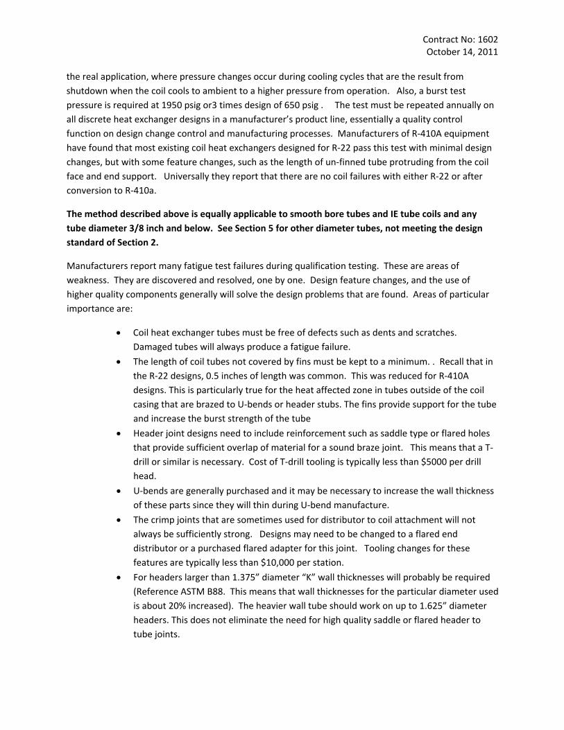
The UL burst test requirements using a design margin of 5 times design pressure is a simple method of demonstrating adequate margin of safety against pressure. National codes and standards typically allow a more careful examination of the actual conditions through more sophisticated tests and/or analysis. See Section A1 for more discussion. Regarding coils used in air conditioning products, UL 1995 Clause 62 (Fatigue Test Analysis), provides an alternative method. This method is a more sophisticated alternative engineering method, employs well known and demonstrated engineering principles, and is very rigorous because it subjects samples to real world stresses. For this method, test samples are subjected to a 250,000 cycle pressure test between low and high side design pressures for the actual application, followed by a burst test at 3 times the design pressure. This method recognizes
Contract No: 1602 October 14, 2011
the real application, where pressure changes occur during cooling cycles that are the result from shutdown when the coil cools to ambient to a higher pressure from operation. Also, a burst test pressure is required at 1950 psig or3 times design of 650 psig . The test must be repeated annually on all discrete heat exchanger designs in a manufacturer’s product line, essentially a quality control function on design change control and manufacturing processes. Manufacturers of R‐410A equipment have found that most existing coil heat exchangers designed for R‐22 pass this test with minimal design changes, but with some feature changes, such as the length of un‐finned tube protruding from the coil face and end support. Universally they report that there are no coil failures with either R‐22 or after conversion to R‐410a.
The method described above is equally applicable to smooth bore tubes and IE tube coils and any tube diameter 3/8 inch and below. See Section 5 for other diameter tubes, not meeting the design standard of Section 2.
Manufacturers report many fatigue test failures during qualification testing. These are areas of weakness. They are discovered and resolved, one by one. Design feature changes, and the use of higher quality components generally will solve the design problems that are found. Areas of particular importance are:
• Coil heat exchanger tubes must be free of defects such as dents and scratches. Damaged tubes will always produce a fatigue failure.
• The length of coil tubes not covered by fins must be kept to a minimum. . Recall that in the R‐22 designs, 0.5 inches of length was common. This was reduced for R‐410A designs. This is particularly true for the heat affected zone in tubes outside of the coil casing that are brazed to U‐bends or header stubs. The fins provide support for the tube and increase the burst strength of the tube
• Header joint designs need to include reinforcement such as saddle type or flared holes that provide sufficient overlap of material for a sound braze joint. This means that a T‐drill or similar is necessary. Cost of T‐drill tooling is typically less than $5000 per drill head.
• U‐bends are generally purchased and it may be necessary to increase the wall thickness of these parts since they will thin during U‐bend manufacture.
• The crimp joints that are sometimes used for distributor to coil attachment will not always be sufficiently strong. Designs may need to be changed to a flared end distributor or a purchased flared adapter for this joint. Tooling changes for these features are typically less than $10,000 per station.
• For headers larger than 1.375” diameter “K” wall thicknesses will probably be required (Reference ASTM B88. This means that wall thicknesses for the particular diameter used is about 20% increased). The heavier wall tube should work on up to 1.625” diameter headers. This does not eliminate the need for high quality saddle or flared header to tube joints.
Contract No: 1602 October 14, 2011
• Brazing quality must be carefully controlled. Especially important are standard brazing
procedures and qualification of the manufacturing technician, use of a nitrogen purge during brazing and routine inspection to insure quality. Nitrogen purge is used to insure cleanliness inside the refrigeration system and pressure integrity of the joint. Nitrogen is typically provided in bottle form at the brazing station. Bulk tanks and piping could be used for very high volume production. Careless brazing is the largest single source of leaks, which is the largest single warranty expense for manufacturers, and is especially problematic with higher pressure R‐410A.
Purchase or lease of fatigue test equipment that can induce rapid pressure cycles using hydraulic fluids will be a direct cost associated with the changeover to R‐410A. This cost will vary depending on the size and number of testers required to support a particular facility. One manufacturer of unitary equipment reports a capital cost of $100 K for a fatigue test facility for a multi‐port tester, so the capital cost in not trivial. This facility tests multiple large coils at once, and was booked solid during the years of engineering work leading to R‐410A conversion. A single port tester designed for smaller residential coils is estimated to cost $30,000. All facilities are automated to rapidly run the fatigue test in a reasonable period of time. Facility cost is more a function of the number of ports than the physical size of the tester.
An institution or private service provider could purchase and install the necessary facilities for use for a group of manufacturers. In this case the service is provided as an expense, rather than a capital acquisition or lease. One manufacturer reports that the cost of a single test at an agency is approximately $4000. Multiple tests of a typical design would be normal to pass the fatigue requirements. Then the design features would be used over an entire product family. However, since coil features do change over a product line (additional rows and differences in headers for example), it would be prudent that the final designs of each coil be final tested wherever any design feature is different. In doing so it would not be unusual to have a finding or two. The total expense can be estimated and compared with investing in a test facility. For purposes of the exercise assume 5 sizes of product within a family are manufactured, each with slightly different features that affect pressure integrity. Further assume that a small single port tester costing $30,000 could serve the need for qualification testing.
Basic design qualification = 4 tests @ $4000 = $16,000
Final check of each size, with 2 retests due to test findings = (5 + 2) @ $4000 = $28,000
Total Expense = $44,000
Cost of a Test Facility = $30,000 + labor to run the tests + incidentals (energy, spare parts, maintenance)
The above represents a realistic number of tests for the given scenario. Obviously the number of coil variations is driving a large part of the expense. In this case, depending on financing available to a particular company, a rational choice can be made between expense or capital investment. Since there are ongoing expenses to run a test facility, the capital investment choice is typically more attractive if
Contract No: 1602 October 14, 2011
there is already a permanent lab facility that is engaged in various testing activities as product designs continue to evolve.
As previously noted in the R‐22 baseline discussion, process fluids and mineral oils are carefully chosen and qualified to insure compatibility with R‐22. Systems using R‐410A employ synthetic POE oils, or PVE oils, so different process fluids that do not cause chemical interaction must be used. This is essential engineering work and failure to pay attention to these details will result in breakdown of the oil, and ultimately lead to very expensive compressor failures.
Most manufacturers using round tube heat exchangers for R‐410A continue to use 3/8 inch tubes for all circuit sizes. The lower volume flow rates of R‐410A allow coils tubes to drop to 5/16” diameter (unitary) or 5 mm. or 6 mm. tubes (residential). Residential product will likely see more pressure to use all aluminum coils. All of these are driven by lower cost and will happen over time. These are not related to a R‐22 to R410a conversion per se, although the high density R‐410a makes a change to smaller diameter tube attractive, since pressure drop, a parasitic loss, will not be excessive.
Finally there needs to be a remark about maintaining performance. Maintaining performance during an R‐410A conversion is non‐trivial manufacturing engineering and quality control work. Some areas to pay close attention are:
• Coil Circuiting: Since the volumetric flow rates (or CFM/ton) are different, it follows that coil circuiting will likely change such that the tube surfaces are fed as nearly uniformly as possible. In doing so, performance is maintained or in some case increased. Coil circuit changes generally do not involve tooling changes, just assembly change.
• State of Coil Tooling: The tooling used in manufacturing simply wears out or need maintenance from time to time. A good example is a fin die. Worn dies lead to cracked collars, the main bonding area between the tube and the fin. A poor bond due to a cracked collar will degrade coil performance significantly. No conversion program should be undertaken without an examination of the state of the tooling.
• Brazing: It seems that the universal experience among manufacturers is the inability to maintain high brazing quality. Leaks and other failures within the coil or product assembly, usually found in the field, are very expensive. The higher pressures of R‐410A make this problem especially noteworthy.
• Coil damage during assembly, test, packaging and shipment: Experiences is that R‐410A coils are much more sensitive to leak or failure than R‐22 as a result of manufacturing or shipping damage to coils.
5. Coil Designs not meeting the Design Standard
As discussed in Section 2, prevailing design standards and the use of the methods describe in Section 4 yield a successful conversion from R‐22 to R‐410A. Essentially, any tube diameter 3/8 inch and below can be successfully converted without major cost penalty or investment. It is logical to ask, what happens if the design does not meet the design standard, notably in the area of tube diameter?
Contract No: 1602 October 14, 2011
Reaching back in time, coils were made with 5/8 inch (usually used with R‐12, a lower pressure refrigerant) and ½ inch tubes. So it is possible that an older legacy design is currently manufactured for R‐22 coils.
As discussed earlier, the tube wall thickness increases linearly with pressure. It also increases linearly with tube diameter. So a ½ inch tube, for example, would have a tube wall thickness two times that needed for R‐22 (70% for pressure, 30% for diameter). This is twice the amount of copper and an enormous cost penalty. So, increasing the tube wall thickness, either on the I.D. or O.D. would not be an attractive solution. Assuming that the alternative fatigue method could be employed is a reasonable assumption, but there is really no experience among major manufacturers that would validate it. One other potential solution is a change in the tube alloy for increase strength. But then, special alloys are not cost free, since there is little supply base for this type of coil tube. One must assume that the solution is some combination of the potential changes – thicker walls, different alloys, and use of the fatigue method – but the exact solution will depend on the singular case.
6. Summary of Manufacturing Costs for Conversion
In Section 2, a summary was given of the primary manufacturing processes and tooling. Given below is a summary of the manufacturing tooling changes that might be expected for a typical conversion. There is no major capital cost for conversion.
Fins: NO TOOLING COST
Tube Cut Off: NO TOOLING COST
Hairpin Bender: NO TOOLING COST
Headers: T‐drill or similar must be used. T‐drill is a trade name and other alternatives exist to raise a more robust brazing collar on the header. T‐drill heads cost approximately $5000 per drill head and can be used with the either manual or automated drilling equipment. The basic drilling equipment itself does not change. The number of drilling machines and type is widely variable depending on production volumes.
U‐Bends: NO TOOLING COST
Coil Structural End Plates and Supports: NO TOOLING COST
Coil Assembly: NO TOOLING COST
Tube Expansion: NO TOOLING COST
Headers, U‐bend or Distributor Tubes: Crimping of distributor tube to coil tube estimated to cost less than $10,000 per station. A station is the production facility where the work is performed, usually one per production line.
Pressure and Leak Test: NO TOOLING COST
Final Product Pressure and Leak Test: NO TOOLING COST
Contract No: 1602 October 14, 2011
Process Fluids: Process fluids must be carefully examined for compatibility with R‐410A and POE oil. It should be noted that PVE oil is also used with R‐410A. This is engineering work, but not a manufacturing cost.
Though not a manufacturing tooling cost, a Fatigue Test Facility cost is approximately $100,000 for a large, multiport tester but could range down to $30,000 for a small single port tester.
In cases where current coil designs at a manufacturer do not meet the design standard and it were possible to create an engineering solution as discussed in Section 5, the same capital cost requirements shown above may be assumed. The number of tests needed to qualify a larger diameter tube may be higher than that experienced on small diameter tubes (3/8 inch and below). Also, such manufacturers are also likely to incur significantly increased per‐unit costs through the increased use of copper and/or more pressure resistant alloys, whichever may be applicable.
7. Conclusion
The work done in the period leading up to the 2010 phase out of R‐22 by major manufacturers indicates that R‐410A coils do not require major design changes. Essentially an R‐22 design standard coil will yield the same or better heat transfer and handle the higher pressures. Neither the tube O.D. the I.D, nor the standard materials of construction needed to change. Coil circuiting changes are common to optimize performance within the design space. Regarding pressure, including but not limited to the higher temperatures of the places like the Middle East, coils cannot withstand the typical burst test pressures used to qualify R‐22 coils, and an alternative method to insure safety must be used for R‐410A. Engineering work must focus on fatigue strength rather than simple burst test limits. The broad experience is that a good analytical and test program likely produce a successful design without major change, but small feature changes (such as unsupported tube length). Therefore, the capital equipment to manufacturer R‐410A coils is essentially unchanged. Small tooling changes may very well be necessary, but these are low in cost. For example, a T‐Drill head used on a manual or NC drill press is less than $5000. Of special note is the need for manufacturers to be able to rapidly run fatigue tests on coil features. A common experience was to try a variety of design features in areas of fatigue failure. A facility large enough to handle the largest unitary coils cost approximately $100,000. A fatigue test facility is a non‐trivial capital cost that must be borne by the manufacturer, or provided by an institution or private company that could provide the service economically to several manufacturers on demand. Finally, attention to details, such as process fluids changes, the state of manufacturing tooling, and quality brazing are among the items that cannot be overlooked for a successful conversion. This is engineering work, not generally related to capital or tooling costs.
Contract No: 1602 October 14, 2011
Annex A
Annex A is reserved for more detail on certain subjects or to answer several additional questions that were posed in the inquiry that have not been addressed, but are not central to the issue of manufacturing conversion costs when changing to R410A.
A1. Pressure Design
The subject of pressure design is somewhat complex. Two basic philosophies exist within the global community of codes and standards.
1. Simplified design by rules 2. Sophisticated design by analysis / test
For example, ASME Pressure Vessel Code, Section VIII Div. 1 for the design of unfired pressure vessels gives a thorough, albeit simple and conservative, set of design rules for safe design of pressure vessels. Alternatively, for unusual designs or in cases where there is unusual manufacturing or costs implications a alternative method is given in Div 2. Both methods produce safe design for pressure containment but the Div. 2 is much more sophisticated and demanding.
Pressure vessel codes do not exist for coil designs and other components such as compressors. In these cases, other standards can be found within the international community. For example, in North America, ASHRAE and UL standards are used. In Europe, ISO 5149 and IEC PED are parallel standards that are used. For automotive applications, SAE J 6.9 is widely used throughout the world. All such standards follow a similar pattern to that describe above. These standards usually allow a simple method, or alternative methods using more sophisticated tests and/or analysis.
Regarding fatigue testing, well know engineering methods are applied, but also proven before the standard is adopted. In the case of UL 5149, in the mid‐1990’s work was done within UL and with several manufacturers to demonstrate safety and equivalency of the alternative methods. In doing so, a realistic assessment of the real loading and stresses is necessary. UL reports that over 300 independent tests were done by them, independent of hundred of tests done by various manufacturers to demonstrate that the alternative method that UL finally adopted was indeed safe and equivalent or superior to a simple one‐ time pressure test. ISO 5149 contains a similar method.
A2. Alternative Refrigerants
While this study is not intended to discuss alternative refrigerant choices in great detail, discussion of conversion to a number of alternative refrigerants was requested. R‐410A is the current refrigerant of choice for developed countries for unitary and residential air conditioning systems and therefore a good choice for developing countries. However, any refrigerant choice is ultimately a trade‐off between ODP, GWP , safety and performance as well as wide commercial availability for service. See table below for a comparison of select refrigerants that are suitable for smaller residential and unitary air
Contract No: 1602 October 14, 2011
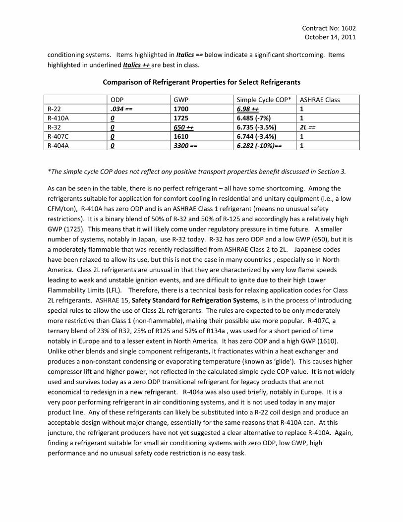
conditioning systems. Items highlighted in Italics == below indicate a significant shortcoming. Items highlighted in underlined Italics ++ are best in class.
Comparison of Refrigerant Properties for Select Refrigerants
ODP GWP Simple Cycle COP* ASHRAE Class R‐22 .034 == 1700 6.98 ++ 1 R‐410A 0 1725 6.485 (‐7%) 1 R‐32 0 650 ++ 6.735 (‐3.5%) 2L == R‐407C 0 1610 6.744 (‐3.4%) 1 R‐404A 0 3300 == 6.282 (‐10%)== 1
*The simple cycle COP does not reflect any positive transport properties benefit discussed in Section 3.
As can be seen in the table, there is no perfect refrigerant – all have some shortcoming. Among the refrigerants suitable for application for comfort cooling in residential and unitary equipment (i.e., a low CFM/ton), R‐410A has zero ODP and is an ASHRAE Class 1 refrigerant (means no unusual safety restrictions). It is a binary blend of 50% of R‐32 and 50% of R‐125 and accordingly has a relatively high GWP (1725). This means that it will likely come under regulatory pressure in time future. A smaller number of systems, notably in Japan, use R‐32 today. R‐32 has zero ODP and a low GWP (650), but it is a moderately flammable that was recently reclassified from ASHRAE Class 2 to 2L. Japanese codes have been relaxed to allow its use, but this is not the case in many countries , especially so in North America. Class 2L refrigerants are unusual in that they are characterized by very low flame speeds leading to weak and unstable ignition events, and are difficult to ignite due to their high Lower Flammability Limits (LFL). Therefore, there is a technical basis for relaxing application codes for Class 2L refrigerants. ASHRAE 15, Safety Standard for Refrigeration Systems, is in the process of introducing special rules to allow the use of Class 2L refrigerants. The rules are expected to be only moderately more restrictive than Class 1 (non‐flammable), making their possible use more popular. R‐407C, a ternary blend of 23% of R32, 25% of R125 and 52% of R134a , was used for a short period of time notably in Europe and to a lesser extent in North America. It has zero ODP and a high GWP (1610). Unlike other blends and single component refrigerants, it fractionates within a heat exchanger and produces a non‐constant condensing or evaporating temperature (known as ‘glide’). This causes higher compressor lift and higher power, not reflected in the calculated simple cycle COP value. It is not widely used and survives today as a zero ODP transitional refrigerant for legacy products that are not economical to redesign in a new refrigerant. R‐404a was also used briefly, notably in Europe. It is a very poor performing refrigerant in air conditioning systems, and it is not used today in any major product line. Any of these refrigerants can likely be substituted into a R‐22 coil design and produce an acceptable design without major change, essentially for the same reasons that R‐410A can. At this juncture, the refrigerant producers have not yet suggested a clear alternative to replace R‐410A. Again, finding a refrigerant suitable for small air conditioning systems with zero ODP, low GWP, high performance and no unusual safety code restriction is no easy task.
Contract No: 1602 October 14, 2011
Conversion to R‐410A in many developed countries was accompanied by performance increases that are required by governments or national codes or standards. It is becoming more understood that the major component of global warming is the power consumption of the air conditioning product during its lifetime of use, not the direct GWP effect of refrigerant leaks. Refrigerant leaks are insignificant in smaller air conditioning systems but not without engineering effort and attention to quality details in manufacturing.
A3. Coil Efficiency
Two inter‐related questions concerning coil efficiency were posed in the inquiry.
1. What is the effect of an increase in the air side surface of 10%, 20% and 50%. This question is essentially the same as a second question in the inquiry relating to the effect of a change in evaporating and condensing temperature.
2. Comment as to the built‐up of dust or dirt at the heat exchanger during regular operation, assuming rare cleaning, and how common these conditions are.
The power consumption of the end use product is the usual performance metric expressed as COP or EER at a set of standard temperatures, or Seasonal Energy Efficiency Rating (e.g. SEER) which represents a mix of temperatures encountered during a typical cooling season.
The difference between the saturated evaporating temperature and the saturated condensing temperature is the pressure difference or ‘lift’ that the compressor must work against. The smaller the difference is, the lower the power consumption.
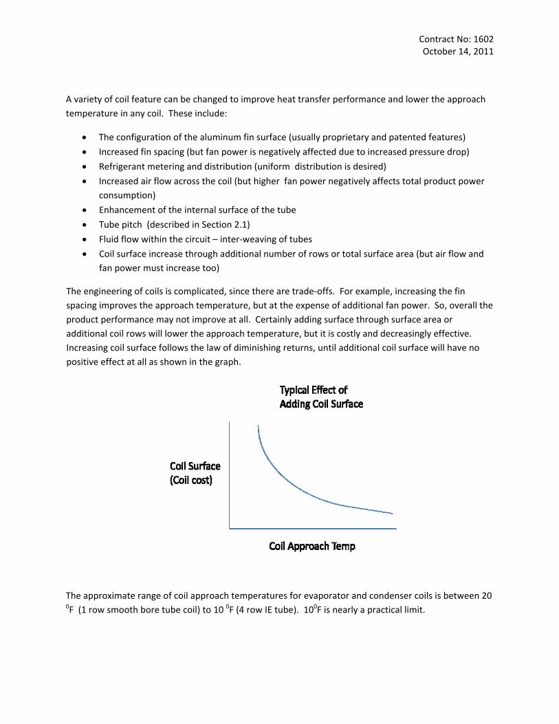
The difference between the ambient temperature and the saturated evaporating or condensing temperature is known as the ‘approach’. The approach temperature is one measure of coil performance. The lower the approach temperature, the lower the lift, and therefore the lower the total power consumed by the compressor (offset by any increase in fan power). A picture may help .
Contract No: 1602 October 14, 2011
A variety of coil feature can be changed to improve heat transfer performance and lower the approach temperature in any coil. These include:
• The configuration of the aluminum fin surface (usually proprietary and patented features)
• Increased fin spacing (but fan power is negatively affected due to increased pressure drop)
• Refrigerant metering and distribution (uniform distribution is desired)
• Increased air flow across the coil (but higher fan power negatively affects total product power consumption)
• Enhancement of the internal surface of the tube
• Tube pitch (described in Section 2.1)
• Fluid flow within the circuit – inter‐weaving of tubes
• Coil surface increase through additional number of rows or total surface area (but air flow and fan power must increase too)
The engineering of coils is complicated, since there are trade‐offs. For example, increasing the fin spacing improves the approach temperature, but at the expense of additional fan power. So, overall the product performance may not improve at all. Certainly adding surface through surface area or additional coil rows will lower the approach temperature, but it is costly and decreasingly effective. Increasing coil surface follows the law of diminishing returns, until additional coil surface will have no positive effect at all as shown in the graph.
The approximate range of coil approach temperatures for evaporator and condenser coils is between 20 0F (1 row smooth bore tube coil) to 10 0F (4 row IE tube). 100F is nearly a practical limit.
Contract No: 1602 October 14, 2011
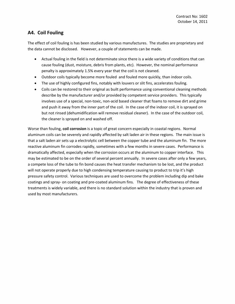
A4. Coil Fouling
The effect of coil fouling is has been studied by various manufactures. The studies are proprietary and the data cannot be disclosed. However, a couple of statements can be made.
• Actual fouling in the field is not determinate since there is a wide variety of conditions that can cause fouling (dust, moisture, debris from plants, etc). However, the nominal performance penalty is approximately 1.5% every year that the coil is not cleaned.
• Outdoor coils typically become more fouled and fouled more quickly, than indoor coils.
• The use of highly configured fins, notably with louvers or slit fins, accelerates fouling.
• Coils can be restored to their original as built performance using conventional cleaning methods describe by the manufacturer and/or provided by competent service providers. This typically involves use of a special, non‐toxic, non‐acid based cleaner that foams to remove dirt and grime and push it away from the inner part of the coil. In the case of the indoor coil, it is sprayed on but not rinsed (dehumidification will remove residual cleaner). In the case of the outdoor coil, the cleaner is sprayed on and washed off.
Worse than fouling, coil corrosion is a topic of great concern especially in coastal regions. Normal aluminum coils can be severely and rapidly affected by salt laden air in these regions. The main issue is that a salt laden air sets up a electrolytic cell between the copper tube and the aluminum fin. The more reactive aluminum fin corrodes rapidly, sometimes with a few months in severe cases. Performance is dramatically affected, especially when the corrosion occurs at the aluminum to copper interface. This may be estimated to be on the order of several percent annually. In severe cases after only a few years, a compete loss of the tube to fin bond causes the heat transfer mechanism to be lost, and the product will not operate properly due to high condensing temperature causing to product to trip it’s high pressure safety control. Various techniques are used to overcome the problem including dip and bake coatings and spray‐ on coating and pre‐coated aluminum fins. The degree of effectiveness of these treatments is widely variable, and there is no standard solution within the industry that is proven and used by most manufacturers.
1
ATTACHMENT II
VIEWS EXPRESSED RELATED TO RETOOLING FOR MANUFACTURING HEAT EXCHANGERS
2
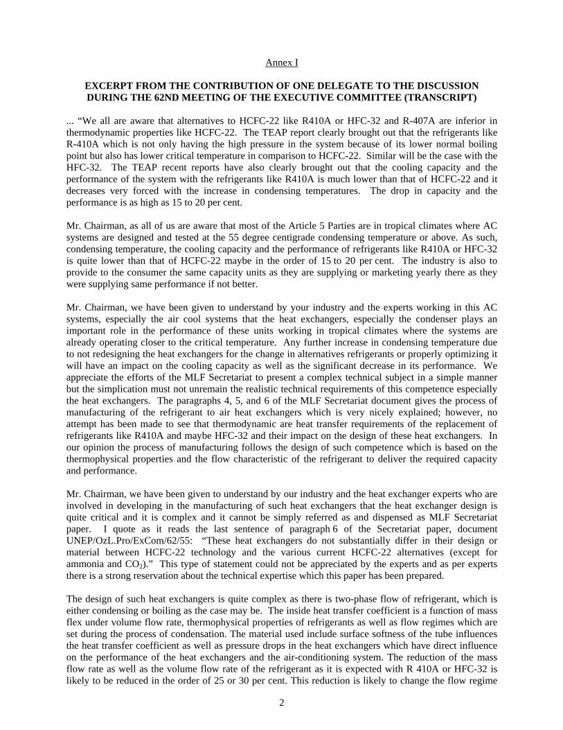
Annex I
EXCERPT FROM THE CONTRIBUTION OF ONE DELEGATE TO THE DISCUSSION DURING THE 62ND MEETING OF THE EXECUTIVE COMMITTEE (TRANSCRIPT)
... “We all are aware that alternatives to HCFC-22 like R410A or HFC-32 and R-407A are inferior in thermodynamic properties like HCFC-22. The TEAP report clearly brought out that the refrigerants like R-410A which is not only having the high pressure in the system because of its lower normal boiling point but also has lower critical temperature in comparison to HCFC-22. Similar will be the case with the HFC-32. The TEAP recent reports have also clearly brought out that the cooling capacity and the performance of the system with the refrigerants like R410A is much lower than that of HCFC-22 and it decreases very forced with the increase in condensing temperatures. The drop in capacity and the performance is as high as 15 to 20 per cent. Mr. Chairman, as all of us are aware that most of the Article 5 Parties are in tropical climates where AC systems are designed and tested at the 55 degree centigrade condensing temperature or above. As such, condensing temperature, the cooling capacity and the performance of refrigerants like R410A or HFC-32 is quite lower than that of HCFC-22 maybe in the order of 15 to 20 per cent. The industry is also to provide to the consumer the same capacity units as they are supplying or marketing yearly there as they were supplying same performance if not better. Mr. Chairman, we have been given to understand by your industry and the experts working in this AC systems, especially the air cool systems that the heat exchangers, especially the condenser plays an important role in the performance of these units working in tropical climates where the systems are already operating closer to the critical temperature. Any further increase in condensing temperature due to not redesigning the heat exchangers for the change in alternatives refrigerants or properly optimizing it will have an impact on the cooling capacity as well as the significant decrease in its performance. We appreciate the efforts of the MLF Secretariat to present a complex technical subject in a simple manner but the simplication must not unremain the realistic technical requirements of this competence especially the heat exchangers. The paragraphs 4, 5, and 6 of the MLF Secretariat document gives the process of manufacturing of the refrigerant to air heat exchangers which is very nicely explained; however, no attempt has been made to see that thermodynamic are heat transfer requirements of the replacement of refrigerants like R410A and maybe HFC-32 and their impact on the design of these heat exchangers. In our opinion the process of manufacturing follows the design of such competence which is based on the thermophysical properties and the flow characteristic of the refrigerant to deliver the required capacity and performance. Mr. Chairman, we have been given to understand by our industry and the heat exchanger experts who are involved in developing in the manufacturing of such heat exchangers that the heat exchanger design is quite critical and it is complex and it cannot be simply referred as and dispensed as MLF Secretariat paper. I quote as it reads the last sentence of paragraph 6 of the Secretariat paper, document UNEP/OzL.Pro/ExCom/62/55: “These heat exchangers do not substantially differ in their design or material between HCFC-22 technology and the various current HCFC-22 alternatives (except for ammonia and CO2).” This type of statement could not be appreciated by the experts and as per experts there is a strong reservation about the technical expertise which this paper has been prepared. The design of such heat exchangers is quite complex as there is two-phase flow of refrigerant, which is either condensing or boiling as the case may be. The inside heat transfer coefficient is a function of mass flex under volume flow rate, thermophysical properties of refrigerants as well as flow regimes which are set during the process of condensation. The material used include surface softness of the tube influences the heat transfer coefficient as well as pressure drops in the heat exchangers which have direct influence on the performance of the heat exchangers and the air-conditioning system. The reduction of the mass flow rate as well as the volume flow rate of the refrigerant as it is expected with R 410A or HFC-32 is likely to be reduced in the order of 25 or 30 per cent. This reduction is likely to change the flow regime
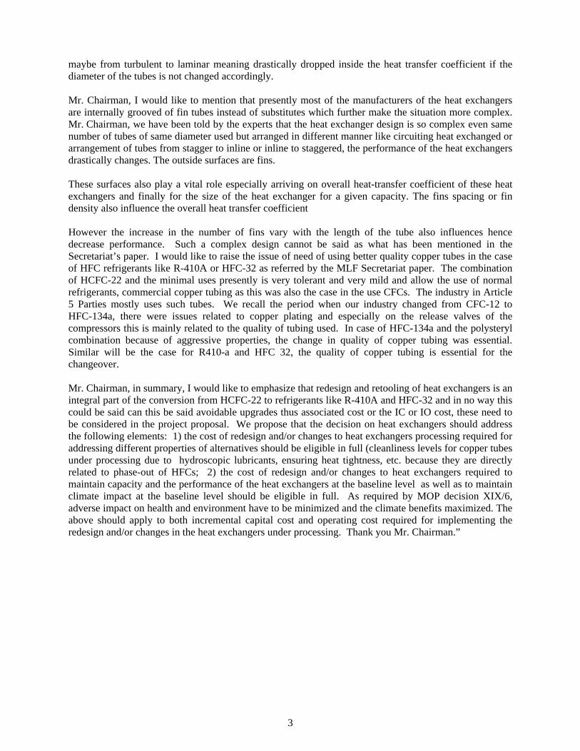
3
maybe from turbulent to laminar meaning drastically dropped inside the heat transfer coefficient if the diameter of the tubes is not changed accordingly. Mr. Chairman, I would like to mention that presently most of the manufacturers of the heat exchangers are internally grooved of fin tubes instead of substitutes which further make the situation more complex. Mr. Chairman, we have been told by the experts that the heat exchanger design is so complex even same number of tubes of same diameter used but arranged in different manner like circuiting heat exchanged or arrangement of tubes from stagger to inline or inline to staggered, the performance of the heat exchangers drastically changes. The outside surfaces are fins. These surfaces also play a vital role especially arriving on overall heat-transfer coefficient of these heat exchangers and finally for the size of the heat exchanger for a given capacity. The fins spacing or fin density also influence the overall heat transfer coefficient However the increase in the number of fins vary with the length of the tube also influences hence decrease performance. Such a complex design cannot be said as what has been mentioned in the Secretariat’s paper. I would like to raise the issue of need of using better quality copper tubes in the case of HFC refrigerants like R-410A or HFC-32 as referred by the MLF Secretariat paper. The combination of HCFC-22 and the minimal uses presently is very tolerant and very mild and allow the use of normal refrigerants, commercial copper tubing as this was also the case in the use CFCs. The industry in Article 5 Parties mostly uses such tubes. We recall the period when our industry changed from CFC-12 to HFC-134a, there were issues related to copper plating and especially on the release valves of the compressors this is mainly related to the quality of tubing used. In case of HFC-134a and the polysteryl combination because of aggressive properties, the change in quality of copper tubing was essential. Similar will be the case for R410-a and HFC 32, the quality of copper tubing is essential for the changeover. Mr. Chairman, in summary, I would like to emphasize that redesign and retooling of heat exchangers is an integral part of the conversion from HCFC-22 to refrigerants like R-410A and HFC-32 and in no way this could be said can this be said avoidable upgrades thus associated cost or the IC or IO cost, these need to be considered in the project proposal. We propose that the decision on heat exchangers should address the following elements: 1) the cost of redesign and/or changes to heat exchangers processing required for addressing different properties of alternatives should be eligible in full (cleanliness levels for copper tubes under processing due to hydroscopic lubricants, ensuring heat tightness, etc. because they are directly related to phase-out of HFCs; 2) the cost of redesign and/or changes to heat exchangers required to maintain capacity and the performance of the heat exchangers at the baseline level as well as to maintain climate impact at the baseline level should be eligible in full. As required by MOP decision XIX/6, adverse impact on health and environment have to be minimized and the climate benefits maximized. The above should apply to both incremental capital cost and operating cost required for implementing the redesign and/or changes in the heat exchangers under processing. Thank you Mr. Chairman.”

Annex II
“ R410A/R22 COMPARISON OF PRESSURE LEVELS”, SUBMITTED BY PETRA ENGINEERING R&D LABS
R410A/R22 Comparison of Pressure levels
R410A refrigerant is a near azeotropic blend. It is widely used in air conditioning applications.
At high ambient temperatures, energy consumption/COP initially seems to be less favorable than with R22. This is mainly due to the thermodynamic properties of this refrigerant. On the other hand, very high isentropic efficiencies are achievable (with reciprocating and scroll compressor), whereby the differences are lower in reality.
The material compatibility is comparable to the previously discussed blends and the same applies for the lubricants. However, the pressure levels and the higher specific loads on the system components need to be taken into account.
The fundamental criteria for HFC blends also apply to the system technology with R410A, however the extreme high pressure levels have to be considered (42 bar at 55°C Ambient temperature).
Compressors and other system components of “Standard Design” have substantial limitations for the application of this refrigerant. However, due to the favorable properties of R410A considerable effort is taken for the development of suitable products.
When considering to cover usual R22 application ranges, the significant differences in the thermodynamic properties (e.g. pressure levels mass and volume flow, vapor density) must be evaluated.
This also requires considerable constructional changes to compressors, heat exchangers, and controls, as well as measures of tuning vibrations.
In addition, safety requirements are concerned also affecting the quality and dimensions of piping and flexible tube elements (for ambient temperatures of approx. 55°C/42 bar).
Another criterion is the relatively low critical temperature of 73°C. Irrespective of the design of components on the high pressure side, the condensing temperature is thus limited.
Page 1 of 2
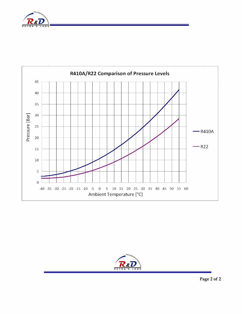
Page 2 of 2
Clarification why changes in the production lines in PETRA company is required for changing from R22 to R410A and why to consider this incremental operating cost of the heat exchanger of PETRA project?
*Changing the toolings and the heat exchanger production machines in Petra production facility is a mandatory to accomplish the demonstration project for the below reasons:
a‐ most of the company current production is for ARTICLE 5 countries(84%) and most of these
production percentage is for the gulf area which has high ambient conditions as the design ambient for this countries is about 46 c and a lot of designer consider it 50 c and if we compare the R410 a refrigerant pressure at this high ambient conditions and the r22 refrigerant we find that the pressure of r410a at this condition is about 550 psig while it is 320 psig using r22 refrigerant ( so the pressure difference is about 230 psig, R410 a is much higher pressure than r22 specially at this high ambient conditions )and the current tube thickness for the heat exchanger coils produced in petra company cannot be used in this case as it is unsafe to use it in this high pressure levels in this article 5 countries and specifically in these high ambient markets which is the major markets for Petra So changing the tube thickness and outside diameter is not a luxury issue it is a mandatory issue to produce these kind of heat exchanger which is suitable for this R410 a refrigerant as it will be unsafe at all to use the current heat exchangers in this application and we see that this change is a vital change required to implement this demonstration project in the right and schedule time as agreed between all concerned parties
b‐ The R410A is a high pressure refrigerant and it is also high GWP refrigerant And the requirement for supplying mechanically and electrically safe units is a major item which all the standards and specifications ask for, keeping the heat exchanger facility as is without changing the tooling will limit the use of this refrigerant (R410a) in the developing countries because simply it is not comply with pressure safety requirements and will lead the consultants and the certification bodies refuse to use this type of refrigerant in the A/C applications and they will prefer to use the r22 refrigerant is it is more safe if we keep the same tube thickness and OD in PETRA facility.
So Petra is recommending now to have a new machine (fin press + hairpin bender + tube benders +pipe
cutting machines ) which can handle the production requirements for ¼ inch OD finned and tube
heat exchanger as Petra have only machines which can produce 3/8 inch OD WITH 0.3
MM TUBE THICKNESS).
c‐ As per UL 1995 American standard which is used in many article 5 countries and as per attached table the minimum tube thickness is 0.6 mm for 3/8 copper pipes and the tubes in the heat exchanger coil must be capable to withstand a pressure of 5 times the normal
working pressure of the r410 a refrigerant at high ambient conditions in the most of article 5 countries while The heat exchanger tube thickness used in petra is about 0.3 mm thick with 3/8 inch OD this tube thickness is cannot withstand this test pressure as per UL1995 STD requirements so using higher thickness is a mandatory for refrigerants (R410A) Please see the attached documents from UL 1995 std which clarify the safety requirements for the minimum tube thickness and pressure tests requirements in this regards.
Recommendations:
We recommend to consider adopting new machines for heat exchanger production line and to consider this incremental operating cost for Petra project AND to adopt this decision in the 63 meeting
as this demonstration project cannot be completed 100% without adopting such changes in the heat exchanger production line of petra engineering ind.