Embed Size (px)
DESCRIPTION
Nr467
Citation preview

Marine Division92571 Neuilly-sur-Seine Cedex- France
Tel: + 33 (0)1 55 24 70 00 - Fax: + 33 (0)1 55 24 70 25Marine Website: http://www.veristar.comEmail: [email protected]
© 2011 Bureau Veritas - All rights reserved
PART A – Classification and Surveys
Chapters 1 – 2 – 3 – 4 – 5 – 6
NR 467.A1 DT R10 E July 2011
Rules for the Classification ofSteel Ships

ARTICLE 1
1.1. - BUREAU VERITAS is a Society the purpose of whose Marine Division (the "Society") is the classi-fication (" Classification ") of any ship or vessel or structure of any type or part of it or system therein col-lectively hereinafter referred to as a "Unit" whether linked to shore, river bed or sea bed or not, whetheroperated or located at sea or in inland waters or partly on land, including submarines, hovercrafts, drillingrigs, offshore installations of any type and of any purpose, their related and ancillary equipment, subseaor not, such as well head and pipelines, mooring legs and mooring points or otherwise as decided by theSociety.
The Society:• prepares and publishes Rules for classification, Guidance Notes and other documents (“Rules”);• issues Certificates, Attestations and Reports following its interventions (“Certificates”);• publishes Registers.
1.2. - The Society also participates in the application of National and International Regulations or Stand-ards, in particular by delegation from different Governments. Those activities are hereafter collectively re-ferred to as " Certification ".1.3. - The Society can also provide services related to Classification and Certification such as ship andcompany safety management certification; ship and port security certification, training activities; all activi-ties and duties incidental thereto such as documentation on any supporting means, software, instrumen-tation, measurements, tests and trials on board.
1.4. - The interventions mentioned in 1.1., 1.2. and 1.3. are referred to as " Services ". The party and/or itsrepresentative requesting the services is hereinafter referred to as the " Client ". The Services are pre-pared and carried out on the assumption that the Clients are aware of the International Maritimeand/or Offshore Industry (the "Industry") practices.1.5. - The Society is neither and may not be considered as an Underwriter, Broker in ship's sale or char-tering, Expert in Unit's valuation, Consulting Engineer, Controller, Naval Architect, Manufacturer, Ship-builder, Repair yard, Charterer or Shipowner who are not relieved of any of their expressed or impliedobligations by the interventions of the Society.
ARTICLE 22.1. - Classification is the appraisement given by the Society for its Client, at a certain date, following sur-veys by its Surveyors along the lines specified in Articles 3 and 4 hereafter on the level of compliance ofa Unit to its Rules or part of them. This appraisement is represented by a class entered on the Certificatesand periodically transcribed in the Society's Register.
2.2. - Certification is carried out by the Society along the same lines as set out in Articles 3 and 4 hereafterand with reference to the applicable National and International Regulations or Standards.
2.3. - It is incumbent upon the Client to maintain the condition of the Unit after surveys, to presentthe Unit for surveys and to inform the Society without delay of circumstances which may affect thegiven appraisement or cause to modify its scope.2.4. - The Client is to give to the Society all access and information necessary for the safe and efficientperformance of the requested Services. The Client is the sole responsible for the conditions of presenta-tion of the Unit for tests, trials and surveys and the conditions under which tests and trials are carried out.
ARTICLE 33.1. - The Rules, procedures and instructions of the Society take into account at the date of theirpreparation the state of currently available and proven technical knowledge of the Industry. Theyare not a standard or a code of construction neither a guide for maintenance, a safety handbookor a guide of professional practices, all of which are assumed to be known in detail and carefullyfollowed at all times by the Client.Committees consisting of personalities from the Industry contribute to the development of those docu-ments.3.2. - The Society only is qualified to apply its Rules and to interpret them. Any reference to themhas no effect unless it involves the Society's intervention.3.3. - The Services of the Society are carried out by professional Surveyors according to the applicableRules and to the Code of Ethics of the Society. Surveyors have authority to decide locally on matters re-lated to classification and certification of the Units, unless the Rules provide otherwise.
3.4. - The operations of the Society in providing its Services are exclusively conducted by way ofrandom inspections and do not in any circumstances involve monitoring or exhaustive verifica-tion.
ARTICLE 4
4.1. - The Society, acting by reference to its Rules:• reviews the construction arrangements of the Units as shown on the documents presented by the Cli-
ent;• conducts surveys at the place of their construction;• classes Units and enters their class in its Register;• surveys periodically the Units in service to note that the requirements for the maintenance of class are
met.
The Client is to inform the Society without delay of circumstances which may cause the date or theextent of the surveys to be changed.
ARTICLE 55.1. - The Society acts as a provider of services. This cannot be construed as an obligation bearingon the Society to obtain a result or as a warranty.5.2. - The certificates issued by the Society pursuant to 5.1. here above are a statement on the levelof compliance of the Unit to its Rules or to the documents of reference for the Services providedfor.In particular, the Society does not engage in any work relating to the design, building, productionor repair checks, neither in the operation of the Units or in their trade, neither in any advisory serv-ices, and cannot be held liable on those accounts. Its certificates cannot be construed as an im-plied or express warranty of safety, fitness for the purpose, seaworthiness of the Unit or of its valuefor sale, insurance or chartering.5.3. - The Society does not declare the acceptance or commissioning of a Unit, nor of its construc-tion in conformity with its design, that being the exclusive responsibility of its owner or builder,respectively.
5.4. - The Services of the Society cannot create any obligation bearing on the Society or constitute anywarranty of proper operation, beyond any representation set forth in the Rules, of any Unit, equipment ormachinery, computer software of any sort or other comparable concepts that has been subject to any sur-vey by the Society.
ARTICLE 66.1. - The Society accepts no responsibility for the use of information related to its Services which was notprovided for the purpose by the Society or with its assistance.
6.2. - If the Services of the Society cause to the Client a damage which is proved to be the directand reasonably foreseeable consequence of an error or omission of the Society, its liability to-wards the Client is limited to ten times the amount of fee paid for the Service having caused thedamage, provided however that this limit shall be subject to a minimum of eight thousand (8,000)Euro, and to a maximum which is the greater of eight hundred thousand (800,000) Euro and oneand a half times the above mentioned fee.The Society bears no liability for indirect or consequential loss such as e.g. loss of revenue, lossof profit, loss of production, loss relative to other contracts and indemnities for termination of oth-er agreements.6.3. - All claims are to be presented to the Society in writing within three months of the date when the Serv-ices were supplied or (if later) the date when the events which are relied on of were first known to the Client,and any claim which is not so presented shall be deemed waived and absolutely barred. Time is to be in-terrupted thereafter with the same periodicity.
ARTICLE 77.1. - Requests for Services are to be in writing.
7.2. - Either the Client or the Society can terminate as of right the requested Services after givingthe other party thirty days' written notice, for convenience, and without prejudice to the provisionsin Article 8 hereunder. 7.3. - The class granted to the concerned Units and the previously issued certificates remain valid until thedate of effect of the notice issued according to 7.2. here above subject to compliance with 2.3. here aboveand Article 8 hereunder.
7.4. - The contract for classification and/or certification of a Unit cannot be transferred neither assigned.
ARTICLE 88.1. - The Services of the Society, whether completed or not, involve, for the part carried out, the paymentof fee upon receipt of the invoice and the reimbursement of the expenses incurred.
8.2. Overdue amounts are increased as of right by interest in accordance with the applicable leg-islation.8.3. - The class of a Unit may be suspended in the event of non-payment of fee after a first unfruitfulnotification to pay.
ARTICLE 9
9.1. - The documents and data provided to or prepared by the Society for its Services, and the informationavailable to the Society, are treated as confidential. However:• clients have access to the data they have provided to the Society and, during the period of classifica-
tion of the Unit for them, to the classification file consisting of survey reports and certificates whichhave been prepared at any time by the Society for the classification of the Unit;
• copy of the documents made available for the classification of the Unit and of available survey reportscan be handed over to another Classification Society, where appropriate, in case of the Unit's transferof class;
• the data relative to the evolution of the Register, to the class suspension and to the survey status of theUnits, as well as general technical information related to hull and equipment damages, are passed onto IACS (International Association of Classification Societies) according to the association workingrules;
• the certificates, documents and information relative to the Units classed with the Society may bereviewed during certificating bodies audits and are disclosed upon order of the concerned governmen-tal or inter-governmental authorities or of a Court having jurisdiction.
The documents and data are subject to a file management plan.
ARTICLE 1010.1. - Any delay or shortcoming in the performance of its Services by the Society arising from an eventnot reasonably foreseeable by or beyond the control of the Society shall be deemed not to be a breach ofcontract.
ARTICLE 1111.1. - In case of diverging opinions during surveys between the Client and the Society's surveyor, the So-ciety may designate another of its surveyors at the request of the Client.
11.2. - Disagreements of a technical nature between the Client and the Society can be submitted by theSociety to the advice of its Marine Advisory Committee.
ARTICLE 1212.1. - Disputes over the Services carried out by delegation of Governments are assessed within theframework of the applicable agreements with the States, international Conventions and national rules.
12.2. - Disputes arising out of the payment of the Society's invoices by the Client are submitted to the Courtof Nanterre, France.
12.3. - Other disputes over the present General Conditions or over the Services of the Society areexclusively submitted to arbitration, by three arbitrators, in London according to the ArbitrationAct 1996 or any statutory modification or re-enactment thereof. The contract between the Societyand the Client shall be governed by English law.
ARTICLE 1313.1. - These General Conditions constitute the sole contractual obligations binding together theSociety and the Client, to the exclusion of all other representation, statements, terms, conditionswhether express or implied. They may be varied in writing by mutual agreement.13.2. - The invalidity of one or more stipulations of the present General Conditions does not affect the va-lidity of the remaining provisions.
13.3. - The definitions herein take precedence over any definitions serving the same purpose which mayappear in other documents issued by the Society.
BV Mod. Ad. ME 545 k - 17 December 2008
MARINE DIVISION
GENERAL CONDITIONS
RULES FOR THE CLASSIFICATION OF SHIPS
Part AClassification and Surveys
Chapters 1 2 3 4 5 6
Chapter 1 PRINCIPLES OF CLASSIFICATION AND CLASS NOTATIONS
Chapter 2 ASSIGNMENT, MAINTENANCE, SUSPENSION AND WITHDRAWAL OF CLASS
Chapter 3 SCOPE OF SURVEYS (All Ships)
Chapter 4 SCOPE OF SURVEYS IN RESPECT OF THE DIFFERENT SERVICES OF SHIPS
Chapter 5 SCOPE OF SURVEYS RELATED TO ADDITIONAL CLASS NOTATIONS
Chapter 6 RETROACTIVE REQUIREMENTS FOR EXISTING SHIPS
July 2011

The English wording of these rules take precedence over editions in other languages.
Unless otherwise specified, these rules apply on July 1st, 2011. The Society may refer to the contents hereof before July 1st, 2011, as and when deemed necessary or appropriate.
2 Bureau Veritas July 2011
CHAPTER 1PRINCIPLES OF CLASSIFICATION
AND CLASS NOTATIONS
Section 1 General Principles of Classification
1 Principles of classification 27
1.1 Purpose of the Rules1.2 General definitions1.3 Meaning of classification, scope and limits1.4 Request for services1.5 Register of ships
2 Rules 28
2.1 Effective date2.2 Equivalence2.3 Novel features2.4 Disagreement and appeal
3 Duties of the Interested Parties 29
3.1 International and national regulations3.2 Surveyor’s intervention3.3 Operation and maintenance of ships3.4 Flag and Port State Control inspections3.5 Use of measuring equipment and of service suppliers3.6 Spare parts
4 Application of statutory requirements by the Society 30
4.1 International and national regulations
Section 2 Classification Notations
1 General 31
1.1 Purpose of the classification notations1.2 Types of notations assigned
2 Class symbol 31
2.1 General
3 Construction marks 31
3.1 General3.2 List of construction marks
4 Service notations and corresponding additional service features 32
4.1 General4.2 Cargo ships4.3 Bulk, ore and combination carriers4.4 Ships carrying liquid cargo in bulk4.5 Ships carrying passengers4.6 Ships for dredging activities4.7 Working ships4.8 Non-propelled units, units with sail propulsion and other units
July 2011 Bureau Veritas 3
4.9 Fishing vessels4.10 High Speed Crafts (HSC)4.11 Miscellaneous units4.12 Ships with gas fuelled propulsion4.13 Icebreaker ships
5 Navigation and operating area notations 43
5.1 Navigation notations5.2 List of navigation notations5.3 Operating area notations
6 Additional class notations 44
6.1 General6.2 VeriSTAR and STAR notations6.3 Availability of machinery (AVM)6.4 Automated machinery systems (AUT)6.5 Integrated ship systems (SYS)6.6 Monitoring equipment (MON)6.7 Comfort on board ships (COMF)6.8 Pollution prevention6.9 Refrigerating installations6.10 Navigation in ice6.11 Navigation in polar waters 6.12 Lifting appliances6.13 Emergency Response Service (ERS)6.14 Other additional class notations6.15 System fitted but not required by the Rules
7 Other notations 55
7.1
Appendix 1 Notations Assigned According to Editions of the Rules Former to June 2000 Edition
1 Application for surveys and correspondence with current notations 56
1.1 General1.2 Phasing out from former to current notations1.3 Application of scope of surveys1.4 Correspondence between former and current notations
4 Bureau Veritas July 2011

CHAPTER 2ASSIGNMENT, MAINTENANCE, SUSPENSION AND WITHDRAWAL OF CLASS
Section 1 Assignment of Class
1 General 63
1.1
2 New building procedure 63
2.1 Ships surveyed by the Society during construction2.2 Other cases2.3 Documentation
3 Ships classed after construction 64
3.1 General3.2 Ships classed with an IACS Society3.3 Ships not classed with an IACS Society
4 Date of initial classification 66
4.1 Definitions
5 Reassignment of class 66
5.1
Section 2 Maintenance of Class
1 General principles of surveys 67
1.1 Survey types1.2 Change of periodicity, postponement or advance of surveys1.3 Extension of scope of survey1.4 General procedure of survey1.5 Appointment of another Surveyor
2 Definitions and procedures related to surveys 68
2.1 General2.2 Terminology related to hull survey2.3 Procedures for thickness measurements2.4 Agreement of firms for in-water survey2.5 Preparations and conditions for surveys2.6 Access to structures2.7 Equipment for surveys2.8 Surveys at sea and anchorage2.9 Repairs and maintenance during voyage2.10 Repairs
3 Certificate of Classification: issue, validity, endorsement and renewal 73
3.1 Issue of Certificate of Classification3.2 Validity of Certificate of Classification, maintenance of class3.3 Endorsement of Certificate of Classification3.4 Status of surveys and recommendations
July 2011 Bureau Veritas 5
4 Class renewal survey 74
4.1 General principles4.2 Normal survey system (SS)4.3 Continuous survey system (CS)4.4 Planned maintenance survey system for machinery (PMS)
5 Other periodical surveys 75
5.1 General5.2 Annual surveys5.3 Intermediate surveys5.4 Bottom survey5.5 Tailshaft survey5.6 Boiler survey5.7 Links between anniversary dates and annual surveys, intermediate surveys and
class renewal surveys
6 Occasional surveys 78
6.1 General6.2 Damage and repair surveys6.3 Port State Control survey6.4 Conversions, alterations and repairs6.5 Quality System audits
7 Change of ownership 79
7.1
8 Lay-up and re-commissioning 79
8.1 General principles
9 Safety Management System 80
9.1
Section 3 Suspension and Withdrawal of Class
1 General 81
1.1 Discontinuance of class1.2 Suspension of class1.3 Withdrawal of class1.4 Suspension / withdrawal of additional class notations
Appendix 1 Planned Maintenance Survey System
1 General 83
1.1
2 Conditions and procedures for the approval of the system 83
2.1 General2.2 Documentation2.3 Information on board2.4 List of items
3 Implementation of the system 84
3.1
6 Bureau Veritas July 2011
4 Retention and withdrawal of the system 84
4.1
5 Surveys 84
5.1 Implementation survey5.2 Annual audit and confirmatory surveys5.3 Damage and repairs
6 Machinery items surveyed on the basis of condition monitoring 85
6.1
Appendix 2 CSM and PMS Systems: Surveys Carried out by the Chief Engineer
1 Conditions 87
1.1
2 Limits of the interventions 87
2.1
3 Procedure for carrying out surveys 87
3.1 General3.2 Main diesel engines3.3 Auxiliary diesel engines3.4 Reciprocating compressors3.5 Coolers, condensers, heaters3.6 Electrical switchboard3.7 a.c. and d.c. generators3.8 Other items (pumps, electric motors, etc.)
4 Records of surveys carried out 88
4.1
5 Confirmatory survey 88
5.1
6 Suspension of the Chief Engineer’s authorization 89
6.1
Appendix 3 Thickness Measurements: Extent, Determination of Locations, Acceptance Criteria
1 General 90
1.1 Aim of the Appendix1.2 Scope of the Appendix
2 Rule requirements for the extent of measurements 90
2.1 General2.2 Class renewal survey: all ships except those submitted to ESP or equivalent2.3 Class renewal survey: ships submitted to ESP or equivalent
3 Number and locations of measurements 92
3.1 General3.2 Locations of points
July 2011 Bureau Veritas 7

4 Acceptance criteria for thickness measurements 94
4.1 General4.2 Criteria4.3 Local and global strength criteria4.4 Buckling strength criterion4.5 Pitting4.6 Hull supporting structure of shipboard fittings associated with towing and
mooring4.7 Ice strengthened structures for ships assigned with additional class notation for
navigation in polar waters
8 Bureau Veritas July 2011

CHAPTER 3SCOPE OF SURVEYS (ALL SHIPS)
Section 1 Annual Survey
1 General 113
1.1
2 Hull 113
2.1 Hull and hull equipment2.2 Hatch covers and coamings
3 Machinery and systems 114
3.1 General machinery installations3.2 Boilers3.3 Electrical machinery and equipment3.4 Fire protection, detection and extinction3.5 General emergency alarm system
Section 2 Intermediate Survey
1 General 117
1.1
2 Hull 117
2.1
Section 3 Class Renewal Survey
1 General 118
1.1
2 Hull and hull equipment 118
2.1 Bottom survey in dry condition2.2 Decks, hatch covers and equipment2.3 Holds and other dry compartments2.4 Tanks2.5 Thickness measurements
3 Machinery and systems 122
3.1 General3.2 Main and auxiliary engines and turbines3.3 Reduction gears, main thrust and intermediate shaft(s)3.4 Pumps and other machinery items 3.5 Systems in machinery spaces3.6 Electrical equipment and installations3.7 Controls3.8 Fire protection, detection and extinction3.9 Hold, ballast and dry spaces water level detectors3.10 Availability of pumping systems
July 2011 Bureau Veritas 9

Section 4 Bottom Survey
1 General 126
1.1
2 Bottom survey in dry condition 126
2.1 General requirements2.2 Bottom survey held within the scope of class renewal survey
3 Bottom in-water survey 126
3.1 General
Section 5 Tailshaft Survey
1 Survey of tailshafts 128
1.1 General1.2 Complete survey1.3 Modified survey
2 Periodical survey of other propulsion systems 128
2.1 Rotating and azimuth thrusters2.2 Vertical axis propellers2.3 Pump jet systems2.4 Pod propulsion systems
Section 6 Boiler Survey
1 Steam boilers 130
1.1
2 Thermal oil heaters 130
2.1
Section 7 Hull Survey for New Construction
1 General 131
1.1
2 Documentation to be available for the Surveyor during construction 131
2.1
3 Ship construction file 131
3.1
4 Newbuilding survey planning 132
4.1
5 Examination and test plan for newbuilding activities 132
5.1
10 Bureau Veritas July 2011

Appendix 1 Class Requirements and Surveys of Laid-up Ships
1 General 133
1.1
2 Safety conditions 133
2.1
3 Preservation measures for lay-up and maintenance 133
3.1 General3.2 Exposed parts of the hull3.3 Internal spaces3.4 Deck fittings3.5 Machinery3.6 Electrical installations3.7 Steering gear3.8 Boilers3.9 Automated installation
4 Lay-up site and mooring arrangements 136
4.1 General4.2 Recommendations for the lay-up site4.3 Recommendations for the mooring arrangements4.4 Review of the mooring arrangements
5 Surveys 137
5.1 Laying-up survey5.2 Annual lay-up condition survey5.3 Re-commissioning survey
July 2011 Bureau Veritas 11

CHAPTER 4SCOPE OF SURVEYS IN RESPECT OF THE DIFFERENT SERVICES OF SHIPS
Section 1 General
1 General 141
1.1
2 Service notations subject to additional surveys 141
2.1
Section 2 Single Skin and Double Skin Bulk Carriers
1 General 143
1.1 Application1.2 Documentation on board1.3 Reporting and evaluation of surveys1.4 Conditions for survey1.5 Access to structures
2 Annual survey 145
2.1 Hatch covers and coamings, weather decks2.2 Cargo holds2.3 Ballast tanks
3 Intermediate survey 147
3.1 Ships 10 years of age or less3.2 Ships between 10 and 15 years of age3.3 Ships over 15 years of age
4 Class renewal survey 148
4.1 Survey programme and preparation for survey4.2 Survey planning meeting4.3 Scope of survey4.4 Hatch covers and coamings4.5 Overall and close-up surveys4.6 Thickness measurements4.7 Tank testing
Section 3 Oil Tankers and Combination Carriers
1 General 161
1.1 Application1.2 Documentation on board1.3 Reporting and evaluation of surveys1.4 Conditions for survey1.5 Access to structures
12 Bureau Veritas July 2011

2 Annual survey - Hull items 162
2.1 Weather decks2.2 Cargo pump rooms and pipe tunnels2.3 Ballast tanks2.4 Emergency towing arrangement2.5 Safe access to tanker bows
3 Annual survey - Cargo machinery items 163
3.1 Cargo area and cargo pump rooms3.2 Instrumentation and safety devices3.3 Fire-fighting systems in cargo area3.4 Inert gas system
4 Intermediate survey - Hull items 164
4.1 General4.2 Ships between 5 and 10 years of age4.3 Ships between 10 and 15 years of age4.4 Ships over 15 years of age
5 Intermediate survey - Cargo machinery items 164
5.1 Cargo area and cargo pump rooms5.2 Inert gas system
6 Class renewal survey - Hull items 165
6.1 Survey programme and preparation for hull survey6.2 Survey planning meeting6.3 Scope of survey6.4 Overall and close-up surveys6.5 Thickness measurements6.6 Tank testing6.7 Cargo piping, area and pump rooms6.8 Emergency towing arrangement
7 Class renewal survey - Cargo machinery items 174
7.1 Cargo area and cargo pump rooms7.2 Fire-fighting systems in cargo area7.3 Inert gas system
Section 4 Chemical Tankers
1 General 176
1.1 Application1.2 Documentation on board1.3 Reporting and evaluation of surveys1.4 Conditions for survey1.5 Access to structures
2 Annual survey - Hull items 177
2.1 Weather decks2.2 Cargo pump rooms and pipe tunnels2.3 Ballast tanks2.4 Emergency towing arrangement
3 Annual survey - Cargo machinery items 177
3.1 Cargo area and cargo pump rooms3.2 Instrumentation and safety devices3.3 Fire-fighting systems in cargo area3.4 Inert gas system and inert/padding/ drying gas
July 2011 Bureau Veritas 13
4 Intermediate survey - Hull items 178
4.1 General4.2 Ships between 5 and 10 years of age4.3 Ships between 10 and 15 years of age4.4 Ships over 15 years of age
5 Intermediate survey - Cargo machinery items 179
5.1 Cargo area and cargo pump rooms5.2 Inert gas system5.3 Personnel protection
6 Class renewal survey - Hull items 180
6.1 Survey program and preparation for survey6.2 Survey planning meeting6.3 Scope of survey6.4 Overall and close-up surveys6.5 Thickness measurements6.6 Tank testing6.7 Cargo piping, cargo pump rooms and cargo tanks6.8 Emergency towing arrangement
7 Class renewal survey - Cargo machinery items 186
7.1 Cargo area and cargo pump rooms7.2 Fire-fighting systems in cargo area7.3 Inert gas system7.4 Personnel protection
Section 5 Liquefied Gas Carriers
1 General 187
1.1 Application
2 Annual survey - Hull items 187
2.1 General2.2 Weather decks and suspect areas2.3 Cargo handling rooms and piping2.4 Other arrangements or devices2.5 Ballast tanks2.6 Emergency towing arrangement
3 Annual survey - Cargo machinery items 188
3.1 Cargo area and cargo pump rooms3.2 Instrumentation and safety devices3.3 Fire-fighting systems in cargo area3.4 Environmental control for cargo containment systems
4 Intermediate survey - Hull items 189
4.1 General4.2 Weather decks, cargo handling rooms and piping4.3 Salt water ballast tanks
5 Intermediate survey - Cargo machinery items 189
5.1 General5.2 Cargo area and cargo pump rooms5.3 Instrumentation and safety devices5.4 Inert gas system5.5 Personnel protection
14 Bureau Veritas July 2011

6 Class renewal survey - Hull items 191
6.1 Preparation for survey6.2 Survey programme6.3 Scope of survey6.4 Overall and close-up surveys6.5 Thickness measurements6.6 Tank testing6.7 Cargo tank structure6.8 Weather decks, cargo handling rooms and piping6.9 Emergency towing arrangement
7 Class renewal survey - Cargo machinery items 195
7.1 Cargo area, cargo pump rooms, cargo compressor rooms7.2 Fire-fighting systems in cargo area7.3 Inert gas system7.4 Personnel protection
8 First loaded voyage of ships carrying liquefied natural gases (LNG) in bulk 196
8.1
9 Revaporisation installation 196
9.1 Application9.2 Annual survey9.3 Intermediate survey9.4 Class renewal survey
10 STL-SPM 198
10.1 Application10.2 Annual survey10.3 Intermediate survey10.4 Class renewal survey10.5 Bottom survey
Section 6 Ro-ro Cargo Ships, Passenger Ships, Ro-ro Passenger Ships
1 General 200
1.1
2 Ro-ro cargo ships - Annual survey 200
2.1 Shell and inner doors 2.2 Internal platforms and ramps2.3 Fire protection, detection and extinction
3 Ro-ro cargo ships - Class renewal survey 201
3.1 Shell and inner doors 3.2 Internal platforms and ramps3.3 Fire protection, detection and extinction
4 Passenger ships - Annual survey 201
4.1 Watertight bulkheads4.2 Openings in shell plating4.3 Miscellaneous
5 Passenger ships - Class renewal survey 202
5.1
July 2011 Bureau Veritas 15
6 Ro-ro passenger ships - Annual and class renewal surveys 202
6.1
Section 7 General Cargo Ships
1 General 203
1.1 Application1.2 Reporting and evaluation of surveys
2 Annual survey 203
2.1 General2.2 Hatch covers and coamings2.3 Cargo holds2.4 Ballast tanks
3 Intermediate survey 204
3.1 General3.2 Ships 15 years of age or less3.3 Ships over 15 years of age
4 Class renewal survey 205
4.1 Preparation for survey4.2 Scope of survey4.3 Hatch covers and coamings4.4 Overall and close-up surveys4.5 Thickness measurements4.6 Tank testing
Section 8 Other Service Notations
1 General 210
1.1
2 Container ship or ship equipped for the carriage of containers 210
2.1 Annual survey2.2 Class renewal survey
3 Livestock carrier 210
3.1 Annual survey3.2 Class renewal survey
4 FLS tanker 210
4.1 Annual survey - Hull items4.2 Annual survey - Cargo machinery items4.3 Intermediate survey - Hull items4.4 Intermediate survey - Cargo machinery items4.5 Class renewal survey - Hull items4.6 Class renewal survey - Cargo machinery items
5 Dredging units 212
5.1 Annual survey5.2 Class renewal survey
16 Bureau Veritas July 2011

6 Tug, salvage tug, escort tug 213
6.1 Annual survey6.2 Class renewal survey
7 Supply vessel-oil product or supply vessel-chemical product 213
7.1 General7.2 Annual survey - Hull items7.3 Annual survey - Cargo machinery items7.4 Intermediate survey - Hull items7.5 Intermediate survey - Cargo machinery items7.6 Class renewal survey - Hull items7.7 Class renewal survey - Cargo machinery items
8 Fire-fighting ship 215
8.1 Annual survey8.2 Class renewal survey
9 Oil recovery ship 216
9.1 Annual survey9.2 Class renewal survey
10 Cable laying ship 216
10.1 Annual survey10.2 Class renewal survey
11 Fishing vessel 217
11.1 Annual survey11.2 Class renewal survey
12 Special service - standby rescue vessel 217
12.1 Annual survey - Rescue arrangement, survivors accommodation and safety equipment
12.2 Annual survey - Towing arrangements12.3 Class renewal survey - Rescue arrangement, survivors accommodation and
safety equipment12.4 Class renewal survey - Towing arrangements
13 Yachts and charter yachts 217
13.1 Intermediate survey - Hull and hull equipment13.2 Intermediate survey - Machinery and systems
Appendix 1 Oil Tanker Longitudinal Strength Assessment
1 General 218
1.1
2 Evaluation of longitudinal strength 218
2.1 Transverse sectional areas2.2 Transverse section modulus2.3 Calculation criteria of section modulus
3 Sampling method of thickness measurements 218
3.1 Extent of evaluation3.2 Sampling method of thickness measurements3.3 Additional measurements3.4 Repair methods
July 2011 Bureau Veritas 17
CHAPTER 5SCOPE OF SURVEYS RELATED TO
ADDITIONAL CLASS NOTATIONS
Section 1 General
1 General 223
1.1
2 Additional class notations subject to additional surveys 223
2.1
Section 2 VeriSTAR and STAR Notations
1 General 225
1.1 Application
2 VeriSTAR-HULL SIS 225
2.1 General2.2 Class renewal survey
3 STAR-HULL 225
3.1 General3.2 Class renewal survey3.3 Suspension and withdrawal of the notation
4 STAR-MACH SIS 227
4.1 General4.2 Annual audit and confirmatory surveys4.3 Risk analysis update
Section 3 Availability of Machinery
1 General 229
1.1
2 Annual survey 229
2.1
3 Class renewal survey 229
3.1
Section 4 Automated Machinery Systems
1 General 230
1.1
2 Annual survey 230
2.1
18 Bureau Veritas July 2011

3 Class renewal survey 230
3.1
Section 5 Integrated Ship Systems
1 General 231
1.1
2 Annual survey 231
2.1 All notations2.2 Notations SYS-NEQ and SYS-NEQ-12.3 Notation SYS-COM2.4 Notations SYS-IBS and SYS-IBS-1
3 Class renewal survey 232
3.1 All notations
Section 6 Monitoring Equipment
1 General 233
1.1 Application
2 MON-HULL 233
2.1 Annual and class renewal survey
3 MON-SHAFT 233
3.1 Tailshaft survey
Section 7 Pollution Prevention
1 General 234
1.1 Application
2 Prevention of sea pollution 234
2.1 First annual survey2.2 Annual survey2.3 Class renewal survey
3 Prevention of air pollution 235
3.1 Annual survey3.2 Class renewal survey
Section 8 Refrigerating Installations
1 General 236
1.1
2 Annual survey 236
2.1 General2.2 Refrigerating plant
July 2011 Bureau Veritas 19

2.3 Refrigerated spaces2.4 Instrumentation and safety devices2.5 Notation -AIRCONT
3 Class renewal survey 237
3.1 General 3.2 Refrigerating plant3.3 Refrigerated spaces3.4 Instrumentation and safety devices3.5 Notation -AIRCONT
Section 9 Arrangements for Navigation in Ice
1 General 238
1.1
2 Class renewal survey 238
2.1 Thickness measurements2.2 Sea chests
Section 10 Other Notations
1 General 239
1.1
2 STRENGTHBOTTOM 239
2.1 Dry-docking survey
3 GRABLOADING and GRAB[X] 239
3.1 Class renewal survey
4 SPM 239
4.1 Annual survey4.2 Class renewal survey
5 DYNAPOS 239
5.1 Annual survey5.2 Class renewal survey
6 VCS 240
6.1 Annual survey6.2 Class renewal survey
7 COVENT 240
7.1 Annual survey7.2 Class renewal survey
8 CARGOCONTROL 240
8.1 Annual survey8.2 Class renewal survey
9 COLD (H tDH, E tDE) 241
9.1 General9.2 Annual survey9.3 Class renewal survey
20 Bureau Veritas July 2011

10 COMF-NOISE, COMF-VIB, COMF+, COMF-NOISE-Pax, COMF-NOISE-Crew, COMF-VIB-Pax, COMF-VIB-Crew 242
10.1 General10.2 Annual survey10.3 Class renewal survey
July 2011 Bureau Veritas 21
CHAPTER 6RETROACTIVE REQUIREMENTS
FOR EXISTING SHIPS
Section 1 General
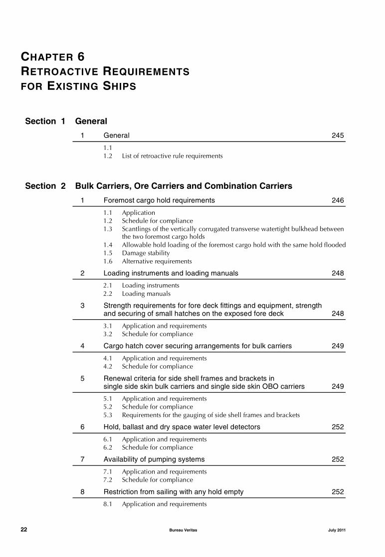
1 General 245
1.1 1.2 List of retroactive rule requirements
Section 2 Bulk Carriers, Ore Carriers and Combination Carriers
1 Foremost cargo hold requirements 246
1.1 Application1.2 Schedule for compliance1.3 Scantlings of the vertically corrugated transverse watertight bulkhead between
the two foremost cargo holds1.4 Allowable hold loading of the foremost cargo hold with the same hold flooded1.5 Damage stability1.6 Alternative requirements
2 Loading instruments and loading manuals 248
2.1 Loading instruments2.2 Loading manuals
3 Strength requirements for fore deck fittings and equipment, strength and securing of small hatches on the exposed fore deck 248
3.1 Application and requirements3.2 Schedule for compliance
4 Cargo hatch cover securing arrangements for bulk carriers 249
4.1 Application and requirements4.2 Schedule for compliance
5 Renewal criteria for side shell frames and brackets in single side skin bulk carriers and single side skin OBO carriers 249
5.1 Application and requirements5.2 Schedule for compliance5.3 Requirements for the gauging of side shell frames and brackets
6 Hold, ballast and dry space water level detectors 252
6.1 Application and requirements6.2 Schedule for compliance
7 Availability of pumping systems 252
7.1 Application and requirements7.2 Schedule for compliance
8 Restriction from sailing with any hold empty 252
8.1 Application and requirements
22 Bureau Veritas July 2011
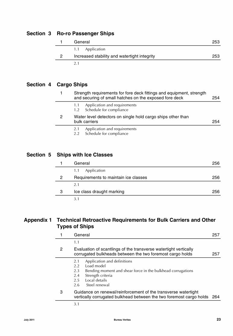
Section 3 Ro-ro Passenger Ships
1 General 253
1.1 Application
2 Increased stability and watertight integrity 253
2.1
Section 4 Cargo Ships
1 Strength requirements for fore deck fittings and equipment, strength and securing of small hatches on the exposed fore deck 254
1.1 Application and requirements1.2 Schedule for compliance
2 Water level detectors on single hold cargo ships other than bulk carriers 254
2.1 Application and requirements2.2 Schedule for compliance
Section 5 Ships with Ice Classes
1 General 256
1.1 Application
2 Requirements to maintain ice classes 256
2.1
3 Ice class draught marking 256
3.1
Appendix 1 Technical Retroactive Requirements for Bulk Carriers and Other Types of Ships
1 General 257
1.1
2 Evaluation of scantlings of the transverse watertight vertically corrugated bulkheads between the two foremost cargo holds 257
2.1 Application and definitions2.2 Load model2.3 Bending moment and shear force in the bulkhead corrugations2.4 Strength criteria2.5 Local details2.6 Steel renewal
3 Guidance on renewal/reinforcement of the transverse watertight vertically corrugated bulkhead between the two foremost cargo holds 264
3.1
July 2011 Bureau Veritas 23
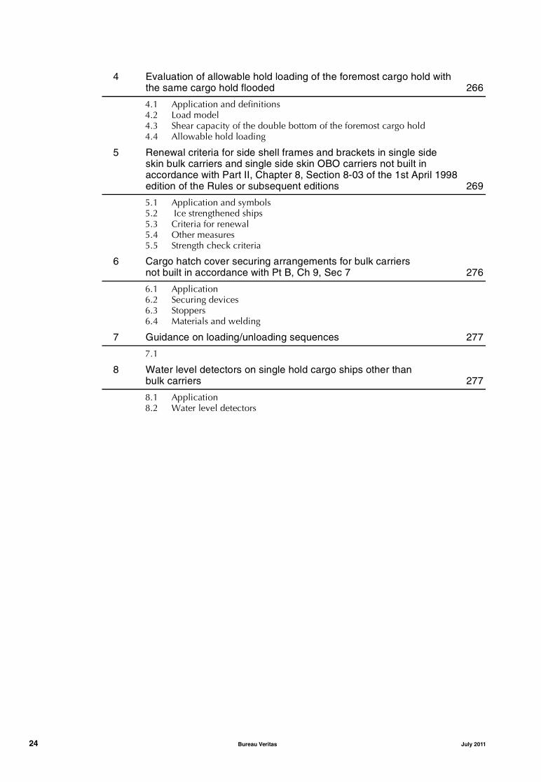
4 Evaluation of allowable hold loading of the foremost cargo hold with the same cargo hold flooded 266
4.1 Application and definitions4.2 Load model4.3 Shear capacity of the double bottom of the foremost cargo hold4.4 Allowable hold loading
5 Renewal criteria for side shell frames and brackets in single side skin bulk carriers and single side skin OBO carriers not built in accordance with Part II, Chapter 8, Section 8-03 of the 1st April 1998 edition of the Rules or subsequent editions 269
5.1 Application and symbols5.2 Ice strengthened ships5.3 Criteria for renewal5.4 Other measures5.5 Strength check criteria
6 Cargo hatch cover securing arrangements for bulk carriers not built in accordance with Pt B, Ch 9, Sec 7 276
6.1 Application6.2 Securing devices6.3 Stoppers6.4 Materials and welding
7 Guidance on loading/unloading sequences 277
7.1
8 Water level detectors on single hold cargo ships other than bulk carriers 277
8.1 Application8.2 Water level detectors
24 Bureau Veritas July 2011

Part AClassification and Surveys
Chapter 1
PRINCIPLES OF CLASSIFICATIONAND CLASS NOTATIONS
SECTION 1 GENERAL PRINCIPLES OF CLASSIFICATION
SECTION 2 CLASSIFICATION NOTATIONS
APPENDIX 1 NOTATIONS ASSIGNED ACCORDING TO EDITIONS OF THE RULES FORMER TO JUNE 2000 EDITION
July 2011 Bureau Veritas 25

26 Bureau Veritas July 2011

Pt A, Ch 1, Sec 1
SECTION 1 GENERAL PRINCIPLES OF CLASSIFICATION
1 Principles of classification
1.1 Purpose of the Rules
1.1.1 The Rules published by the Society give the require-ments for the assignment and the maintenance of classifica-tion for seagoing ships.
Note 1: The general conditions of classification are laid down inthe Marine Division General Conditions.
1.1.2 The application criteria of the different parts of thepresent Rules are the following:
• Part A - Classification and Surveys applies to all ships.
• Part B - Hull and Stability, Part C - Machinery and Sys-tems, Part D - Service Notations apply to seagoing shipswhose hull is of welded steel construction. Where nec-essary, the extent of application is more preciselydefined in each chapter of these parts of the Rules.
• Part E - Additional Class Notations applies, at therequest of the Interested Party, to all ships.
The classification of ships other than those dealt with in theabove-mentioned Parts B, C, D and E is covered by specificRules published by the Society.
1.2 General definitions
1.2.1 The following general definitions are used in theseRules :
• Society means the Classification Society with which theship is classed
• Rules means these Rules for the Classification of Shipsand documents issued by the Society serving the samepurpose
• Surveyor means technical staff acting on behalf of theSociety to perform tasks in relation to classification andsurvey duties
• Survey means an intervention by the Surveyor forassignment or maintenance of class as defined in Part A,Chapter 2, or interventions by the Surveyor within thelimits of the tasks delegated by the Administrations
• Administration means the Government of the Statewhose flag the ship is entitled to fly or the State underwhose authority the ship is operating in the specific case
• Interested Party means a party, other than the Society,having responsibility for the classification of the ship,such as the Owners of a ship and his representatives, orthe Shipbuilder, or the Engine Builder, or the Supplier ofparts to be tested
• Owner means the Registered Owner or the DisponentOwner or the Manager or any other party having theresponsibility to keep the ship seaworthy, having partic-ular regard to the provisions relating to the maintenanceof class laid down in Part A, Chapter 2
• Approval means the review by the Society of documents,procedures or other items related to classification, verify-ing solely their compliance with the relevant Rulesrequirements, or other referentials where requested
• Type approval means an approval process for verifyingcompliance with the Rules of a product, a group ofproducts or a system, and considered by the Society asrepresentative of continuous production
• Essential service is intended to mean a service necessaryfor a ship to proceed at sea, be steered or manoeuvred,or undertake activities connected with its operation, andfor the safety of life, as far as class is concerned.
1.2.2 Definition of date of “contract for construction”:
The date of “contract for construction” of a ship is the dateon which the contract to build the ship is signed betweenthe Owner and the Shipbuilder. This date is normally to bedeclared to the Society by the Interested Party applying forthe assignment of class to a new ship. For ships “contractedfor construction” on or after 1st April 2006, this date and theconstruction numbers (i.e. hull numbers) of all the shipsincluded in the contract, are to be declared to the Societyby the Interested Party applying for the assignment of classto a new ship.
The date of “contract of construction” of a series of ships,including specified optional ships for which the option isultimately exercised, is the date on which the contract tobuild the series is signed between the Owner and the Ship-builder.
For the purpose of this definition, ships built under a singlecontract for construction are considered a “series of ships”if they are built to the same approved plans for classificationpurposes. However, ships within a series may have designalterations from the original design provided:
• Such alterations do not affect matters related to classifi-cation, or
• If the alterations are subject to classification require-ments, these alterations are to comply with the classifi-cation requirements in effect on the date on which thealterations are contracted between the prospectiveOwner and the Shipbuilder or, in the absence of thealteration contract, comply with the classificationrequirements in effect on the date on which the altera-tions are submitted to the Society for approval.
July 2011 Bureau Veritas 27

Pt A, Ch 1, Sec 1
The optional ships will be considered part of the sameseries of ships if the option is exercised not later than 1 yearafter the contract to build the series was signed.
If a contract for construction is later amended to includeadditional ships or additional options, the date of “contractfor construction” for such ships is the date on which theamendment to the contract is signed between the Ownerand the Shipbuilder. The amendment to the contract is to beconsidered as a “new contract” to which the above applies.
If a contract for construction is amended to change the shiptype, the date of “contract for construction” of this modifiedship or ships, is the date on which the revised contract ornew contract is signed between the Owner, or Owners, andthe shipbuilder.
1.3 Meaning of classification, scope and limits
1.3.1 The classification process consists of:
• the development of Rules, guidance notes and otherdocuments relevant to the ship, structure, material,equipment, machinery and other items covered by suchdocuments
• the review of plans and calculations and the surveys,checks and tests intended to demonstrate that the shipmeets the Rules (refer to Ch 2, Sec 1)
• the assignment of class (see Ch 2, Sec 1) and issue of aCertificate of Classification, where compliance with theabove Rules is found
• the periodical, occasional and class renewal surveysperformed to record that the ship in service meets theconditions for maintenance of class (see Ch 2, Sec 2).
1.3.2 The Rules, surveys performed, reports, certificatesand other documents issued by the Society, are in no wayintended to replace or alleviate the duties and responsibili-ties of other parties such as Administrations, Designers,Shipbuilders, Manufacturers, Repairers, Suppliers, Contrac-tors or Sub-contractors, actual or prospective Owners orOperators, Charterers, Brokers, Cargo-owners and Under-writers.
The activities of such parties which fall outside the scope ofthe classification as set out in the Rules, such as design,engineering, manufacturing, operating alternatives, choiceof type and power of machinery and equipment, numberand qualification of crew or operating personnel, lines ofthe ship, trim, hull vibrations, spare parts including theirnumber, location and fastening arrangements, life-savingappliances, and maintenance equipment, remain thereforethe responsibility of those parties, even if these matters maybe given consideration for classification according to thetype of ship or additional class notation assigned.
1.3.3 Unless otherwise specified, the Rules do not dealwith structures, pressure vessels, machinery and equipmentwhich are not permanently installed and used solely foroperational activities such as dredging or heavy load lifting,workshops or welding equipment, except for their effect onthe classification-related matters, as declared by the Inter-ested Party, such as fire protection and ship’s generalstrength.
During periods of construction, modification or repair, theunit is solely under the responsibility of the builder or therepair yard. As an example, the builder or repair yard is toensure that the construction, modification or repair activi-ties are compatible with the design strength of the ship andthat no permanent deformations are sustained.
Note 1: Refer to [3.3] as regards the Owner’s responsibility formaintenance and operation of the ship in relation to the mainte-nance of class.
1.3.4 The class assigned to a ship by the Society followingits interventions is embodied in a Certificate of Classifica-tion and noted in the Register of ships.
At a certain date the class of a ship is maintained or regularwhen no surveys are overdue, when the conditions for sus-pension of class are not met and when the class is not with-drawn nor suspended. Otherwise the class is irregular.Attention is drawn on the fact that a ship holding a validCertificate of Classification may be in an irregular classposition.
1.4 Request for services
1.4.1 Requests for interventions by the Society, such as sur-veys during construction, surveys of ships in service, tests,etc., are in principle to be submitted in writing and signedby the Interested Party. Such request implies that the appli-cant will abide by all the relevant requirements of the Rules,including the Marine Division General Conditions.
The Society reserves the right to refuse or withdraw the classof any ship for which any applicable requirement of theRules is not complied with.
1.5 Register of ships
1.5.1 A Register of Ships is published periodically by theSociety. This publication, which is updated by the Society,contains the names of ships which have received the Certif-icate of Classification, as well as particulars of the classassigned and information concerning each ship.
2 Rules
2.1 Effective date
2.1.1 The effective date of entry into force of any amend-ments to the Rules is indicated on the inside front page ofthe Rules or in the relevant Section.
2.1.2 In principle, the applicable Rules for assignment ofclass to a new ship are those in force at the date of contractfor construction.
28 Bureau Veritas July 2011

Pt A, Ch 1, Sec 1
2.1.3 Special consideration may be given to applying newor modified rule requirements which entered into force sub-sequent to the date of contract for construction, at the dis-cretion of the Society and in the following cases:
• when a justified written request is received from theparty applying for classification
• when the keel is not yet laid and more than one year haselapsed since the contract for construction was signed
• where it is intended to use existing previously approvedplans for a new contract.
2.1.4 The above procedures for application of the Rulesare, in principle, also applicable to existing ships in the caseof major conversions and, in the case of alterations, to thealtered parts of the ship.
2.1.5 The rule requirements related to assignment, mainte-nance and withdrawal of the class of ships already in opera-tion, as detailed in Part A, Chapter 2 to Part A, Chapter 5,are applicable from the date of their entry into force.
2.2 Equivalence
2.2.1 The Society may consider the acceptance of alterna-tives to these Rules, provided that they are deemed to beequivalent to the Rules to the satisfaction to the Society.
2.3 Novel features
2.3.1 The Society may consider the classification of shipsbased on or applying novel design principles or features, towhich the Rules are not directly applicable, on the basis ofexperiments, calculations or other supporting informationprovided to the Society. Specific limitations may then beindicated on the Certificate of Classification.
2.4 Disagreement and appeal
2.4.1 Any technical disagreement with the Surveyor in con-nection with the performance of his duties should be raisedby the Interested Party as soon as possible.
The Interested Party may appeal in writing to the Society,which will subsequently consider the matter and announceits decision according to its established procedure.
3 Duties of the Interested Parties
3.1 International and national regulations
3.1.1 The classification of a ship does not relieve the Inter-ested Party from compliance with any requirements issuedby Administrations.
Note 1: Attention is drawn on the prohibition of asbestos on-boardships (new ships, modified parts of existing ships) and otherNational Regulations, as applicable.
3.2 Surveyor’s intervention
3.2.1 Surveyors are to be given free access at all times toships which are classed or being classed, shipyards andworks, to carry out their interventions within the scope ofassignment or maintenance of class, or within the scope ofinterventions carried out on behalf of Administrations,when so delegated.
Free access is also to be given to auditors accompanying theSurveyors of the Society within the scope of the audits asrequired in pursuance of the Society’s internal Quality Sys-tem or as required by external organizations.
3.2.2 Interested Parties are to take the necessary measuresfor the Surveyors’ inspections and testing to be carried outsafely. Interested Parties - irrespective of the nature of theservice provided by the Surveyors of the Society or othersacting on its behalf - assume with respect to such Surveyorsall the responsibility of an employer for his workforce suchas to meet the provisions of applicable legislation. As a rule,the Surveyor is to be constantly accompanied during sur-veys by personnel of the Interested Party.
Interested Parties are to inform promptly the Surveyor ofdefects or problems in relation to class.
Refer also to Ch 2, Sec 2, [2.5] to Ch 2, Sec 2, [2.8].
3.2.3 The Certificate of Classification and/or other docu-ments issued by the Society remain the property of the Soci-ety. All certificates and documents necessary to theSurveyor’s interventions are to be made available by theInterested Party to the Surveyor on request.
3.2.4 During the phases of ship design and construction,due consideration should be given to rule requirements inrespect of all necessary arrangements for access to spacesand structures with a view to carrying out class surveys.Arrangements of a special nature are to be brought to theattention of the Society.
3.3 Operation and maintenance of ships
3.3.1 The classification of a ship is based on the under-standing that the ship is loaded and operated in a propermanner by competent and qualified crew or operating per-sonnel according to the environmental, loading, operatingand other criteria on which classification is based.
In particular, it will be assumed that the draught of the shipin operating conditions will not exceed that correspondingto the freeboard assigned or the maximum approved for theclassification, that the ship will be properly loaded takinginto account both its stability and the stresses imposed onits structures and that cargoes will be properly stowed andsuitably secured and that the speed and course of the shipare adapted to the prevailing sea and weather conditionsaccording to the normal prudent seamanship.
3.3.2 Ships are to be maintained at all times, at the dili-gence of the Owners, in proper condition complying withinternational safety and pollution prevention regulations.
July 2011 Bureau Veritas 29

Pt A, Ch 1, Sec 1
3.3.3 Any document issued by the Society in relation to itsinterventions reflects the condition of the ship as found atthe time and within the scope of the survey. It is the Inter-ested Party’s responsibility to ensure proper maintenance ofthe ship until the next survey required by the Rules. It is theduty of the Interested Party to inform the Surveyor when heboards the ship of any events or circumstances affecting theclass.
3.4 Flag and Port State Control inspections
3.4.1 Where defects are found further to an inspection byan Administration in pursuance of Port State Control or sim-ilar programmes, Owners are to:• immediately report the outcome of this inspection to the
Society, and• ask the Society to perform an occasional survey in order
to verify that the deficiencies, when related to the classof the ship or to the statutory certificates issued by theSociety on behalf of the flag Administration, are recti-fied and/or the necessary repair work is carried outwithin the due time.
3.5 Use of measuring equipment and of service suppliers
3.5.1 GeneralFirms providing services on behalf of the Interested Party,such as measurements, tests and servicing of safety systemsand equipment, the results of which may form the basis forthe Surveyor’s decisions, are subject to the acceptance ofthe Society, as deemed necessary.
The equipment used during tests and inspections in work-shops, shipyards and on board ships, the results of whichmay form the basis for the Surveyor’s decisions, is to be cus-tomary for the checks to be performed. Firms are to individ-ually identify and calibrate to a national or internationalstandard each piece of such equipment.Note 1: Refer to Rule Note NR 533 Approval of Service Suppliers.
3.5.2 Simple measuring equipmentThe Surveyor may accept simple measuring equipment (e.g.rulers, tape measures, weld gauges, micrometers) withoutindividual identification or confirmation of calibration, pro-vided it is of standard commercial design, properly main-tained and periodically compared with other similarequipment or test pieces.
3.5.3 Shipboard measuring equipmentThe Surveyor may accept measuring equipment fitted onboard a ship (e.g. pressure, temperature or rpm gauges andmeters) and used in examination of shipboard machineryand/or equipment based either on calibration records orcomparison of readings with multiple instruments.
3.6 Spare parts
3.6.1 It is the Owner’s responsibility to decide whether andwhich spare parts are to be carried on board.
3.6.2 As spare parts are outside the scope of classification,the Surveyor will not check that they are kept on board,maintained in a satisfactory condition, or suitably protectedand lashed.
However, in the case of repairs or replacement, the spareparts used are to meet the requirements of the Rules as faras practicable; refer to Ch 2, Sec 2, [6.4.2].
4 Application of statutory requirements by the Society
4.1 International and national regulations
4.1.1 Where requirements of International Conventions,such as SOLAS, ILLC, MARPOL, ILO or of IMO AssemblyResolutions, are quoted as excerpts, they are printed initalic type replacing the word “Administration” with “Soci-ety”.
These requirements are quoted for ease of reference.
4.1.2 When authorised by the Administration concerned,the Society will act on its behalf within the limits of suchauthorisation. In this respect, the Society will take intoaccount the relevant national requirements, survey the ship,report and issue or contribute to the issue of the corre-sponding certificates.
The above surveys do not fall within the scope of the classi-fication of ships, even though their scope may overlap inpart and may be carried out concurrently with surveys forassignment or maintenance of class.
4.1.3 In the case of a discrepancy between the provisionsof the applicable international and national regulations andthose of the Rules, normally, the former take precedence.However, the Society reserves the right to call for the neces-sary adaptation to preserve the intention of the Rules or toapply the provisions of [1.4.1].
4.1.4 In statutory matters, when authorized by the Adminis-tration concerned and acting on its behalf, the Societyapplies the available IACS Unified Interpretations (UIs),unless the Administration provides another interpretation ordecides otherwise.
30 Bureau Veritas July 2011

Pt A, Ch 1, Sec 2
SECTION 2 CLASSIFICATION NOTATIONS
1 General
1.1 Purpose of the classification notations
1.1.1 The classification notations give the scope accordingto which the class of the ship has been based and refer to thespecific rule requirements which are to be complied with fortheir assignment. In particular, the classification notations areassigned according to the type, service and navigation of theship and other criteria which have been provided by theInterested Party, when applying for classification.The Society may change the classification notations at anytime, when the information available shows that therequested or already assigned notations are not suitable forthe intended service, navigation and any other criteria takeninto account for classification.Note 1: Reference should be made to Ch 1, Sec 1, [1.3] on the lim-its of classification and its meaning.
1.1.2 The classification notations assigned to a ship areindicated on the Certificate of Classification, as well as inthe Register of Ships published by the Society.
1.1.3 The classification notations assigned to ships andunits, other than those covered in Parts B, C, D and E, whichare to comply with specific Rules published by the Societyare given in Ch 1, App 1.
1.1.4 The classification notations applicable to existingships conform to the Rules of the Society in force at the dateof assignment of class, as indicated in Ch 2, Sec 1. How-ever, the classification notations of existing ships may beupdated according to the current Rules, as far as applicable.
1.2 Types of notations assigned
1.2.1 The types of classification notations assigned to aship are the following:
a) class symbol
b) construction marks
c) service notations with additional service features, asapplicable
d) navigation notations
e) operating area notations (optional)
f) additional class notations (optional)The different classification notations and their conditions ofassignment are listed in [2] to [6], according to their types.
1.2.2 As an example, the classification notations assignedto a ship may be as follows (the kind of notation shown inbrackets does not form part of the classification notationindicated in the Register of Ships and on the Certificate ofClassification):
I { HULL [ MACH
(class symbol, construction marks)
Oil tanker-Chemical tanker-ESP-Flash point > 60°C
(service notation and additional service features)
Unrestricted navigation
(navigation notation)
{ SYS-IBS-1
(additional class notation).
2 Class symbol
2.1 General
2.1.1 The class symbol expresses the degree of complianceof the ship with the rule requirements as regards its con-struction and maintenance. There is one class symbol,which is compulsory for every classed ship.
2.1.2 The class symbol I is assigned to ships built inaccordance with the requirements of the Rules or otherrules recognised as equivalent, and maintained in a condi-tion considered satisfactory by the Society.
The period of class (or interval between class renewal sur-veys) assigned to class symbol I ships is maximum 5 years,see Ch 2, Sec 2, [4].
Note 1: The class symbol I is to be understood as being the highestclass granted by the Society.
2.1.3 The class symbol II is assigned to ships which do notmeet all requirements for class symbol I, but are deemedacceptable to be entered into the Register of Ships.
The period of class assigned to class symbol II ships is max-imum 3 years, see Ch 2, Sec 2, [4].
2.1.4 Except for special cases, class is assigned to a shiponly when the hull, propulsion and auxiliary machineryinstallations, and equipment providing essential serviceshave all been reviewed in relation to the requirements ofthe Rules.
3 Construction marks
3.1 General
3.1.1 The construction mark identifies the procedure underwhich the ship and its main equipment or arrangementshave been surveyed for initial assignment of the class. Theprocedures under which the ship is assigned one of the con-struction marks are detailed in Ch 2, Sec 1.
July 2011 Bureau Veritas 31

Pt A, Ch 1, Sec 2
3.1.2 One of the construction marks defined below isassigned separately to the hull of the ship and its append-ages, to the machinery installation, and to some installa-tions for which an additional classification notation (see [6]below) is assigned.The construction mark is placed before the symbol HULLfor the hull, before the symbol MACH for the machineryinstallations, and before the additional class notationgranted, when such a notation is eligible for a constructionmark.
If the ship has no machinery installations covered by classi-fication, the symbol MACH is not granted and the construc-tion mark will be only placed before the symbol HULL.Note 1: Ships assigned with the service notation yacht or charteryacht according to the requirements of [4.11.3] and having a lengthless than 24 m may be assigned the construction mark only placedbefore the symbol HULL when the machinery installations are notsurveyed for classification. No symbol MACH is granted in this case.
3.1.3 The construction marks refer to the original conditionof the ship. However, the Society may change the construc-tion mark where the ship is subjected to repairs, conversionor alterations.
3.2 List of construction marks
3.2.1 The mark { is assigned to the relevant part of theship, when it has been surveyed by the Society during itsconstruction in compliance with the new building proce-dure detailed in Ch 2, Sec 1, [2.1], or when it is changing
class from an IACS Society at ship's delivery or when classis being added to an IACS Society's class at ship's deliveryin accordance with specific procedures.
3.2.2 The mark [ is assigned to the relevant part of theship, when the latter is classed after construction in compli-ance with the procedure detailed in Ch 2, Sec 1, [3.2] and itis changing class from an IACS Society at the time of theadmission to class.
3.2.3 The mark µ is assigned to the relevant part of the ship,where the procedure for the assignment of classification isother than those detailed in [3.2.1] and [3.2.2], but how-ever deemed acceptable.
4 Service notations and corresponding additional service features
4.1 General
4.1.1 The service notations define the type and/or serviceof the ship which have been considered for its classifica-tion, according to the request for classification signed bythe Interested Party. At least one service notation is to beassigned to every classed ship.Note 1: The service notations applicable to existing ships conformto the Rules of the Society in force at the date of assignment ofclass. However, the service notations of existing ships may beupdated according to the current Rules, as far as applicable, at therequest of the Interested Party.
Table 1 : List of service notations and additional service features
Service notation [ref. in Part A] Reference Corresponding type of ship according toConventions and/or CodesAdditional service feature Reference
Asphalt carrier [4.4.3] Part D, Chapter 7
Barge [4.8.1] Part D, Chapter 19
tug combined Pt D, Ch 14, Sec 3
type of cargo (1) −Bulk carrier [4.3] − Cargo ship (SOLAS, Reg I/2(g))
Bulk carrier (SOLAS, Reg XII/1)ESP Part D, Chapter 4SOLAS, Reg IX/1.6SOLAS, Reg XI-1/2
BC-A or BC-B or BC-C (2) Part D, Chapter 4
heavycargo [AREA1, X1 kN/m2 - …] Pt B, Ch 5, Sec 6
nonhomload (3) −CSR Rule Note NR 522
GRAB [X] (4) NR 522, Ch 12, Sec 1
CPS(WBT) (5) Rule Note NR 530
Cable laying ship [4.7.6] Part D, Chapter 18 Cargo ship (SOLAS, Reg I/2(g))
Chemical tanker [4.4.4] Part D, Chapter 8 Chemical tanker (SOLAS, Reg.II-2/3.11, Reg.VII /8.2)Chemical tanker (MARPOL Annex II, Reg 1/16.1) whennoxious liquid substances are loaded
ESP
type of cargo (1)
Combination carrier/OBO ESP [4.3.4] Part D, Chapter 6 Combination carrier (SOLAS, Reg II-2/3.14)Tanker (SOLAS, Reg I/2(h))Bulk carrier (SOLAS, Reg IX/1.6, Reg XII/1)Oil tanker - Combination carrier (MARPOL Annex I, Reg I/1.8)
32 Bureau Veritas July 2011
Pt A, Ch 1, Sec 2
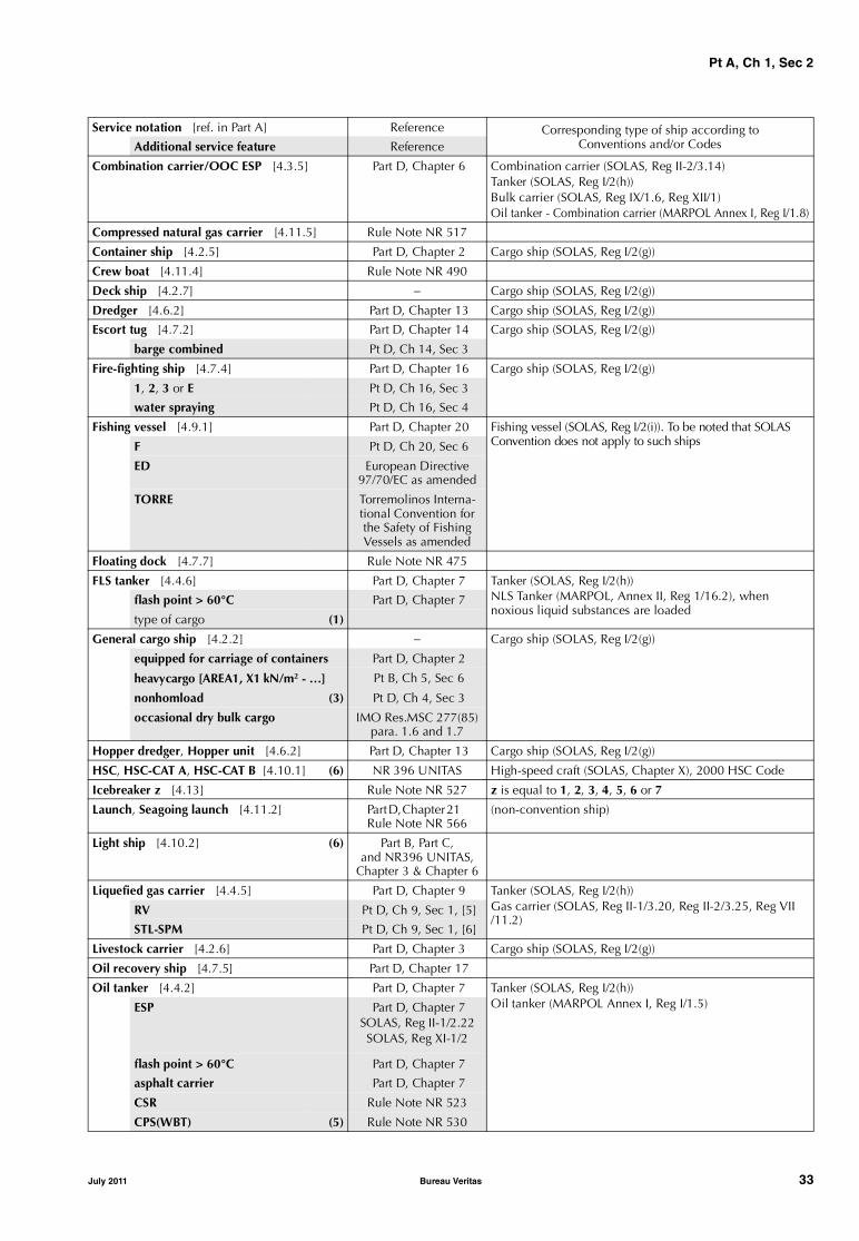
Combination carrier/OOC ESP [4.3.5] Part D, Chapter 6 Combination carrier (SOLAS, Reg II-2/3.14)Tanker (SOLAS, Reg I/2(h))Bulk carrier (SOLAS, Reg IX/1.6, Reg XII/1)Oil tanker - Combination carrier (MARPOL Annex I, Reg I/1.8)
Compressed natural gas carrier [4.11.5] Rule Note NR 517
Container ship [4.2.5] Part D, Chapter 2 Cargo ship (SOLAS, Reg I/2(g))
Crew boat [4.11.4] Rule Note NR 490
Deck ship [4.2.7] − Cargo ship (SOLAS, Reg I/2(g))
Dredger [4.6.2] Part D, Chapter 13 Cargo ship (SOLAS, Reg I/2(g))
Escort tug [4.7.2] Part D, Chapter 14 Cargo ship (SOLAS, Reg I/2(g))
barge combined Pt D, Ch 14, Sec 3
Fire-fighting ship [4.7.4] Part D, Chapter 16 Cargo ship (SOLAS, Reg I/2(g))
1, 2, 3 or E Pt D, Ch 16, Sec 3
water spraying Pt D, Ch 16, Sec 4
Fishing vessel [4.9.1] Part D, Chapter 20 Fishing vessel (SOLAS, Reg I/2(i)). To be noted that SOLAS Convention does not apply to such shipsF Pt D, Ch 20, Sec 6
ED European Directive 97/70/EC as amended
TORRE Torremolinos Interna-tional Convention for the Safety of FishingVessels as amended
Floating dock [4.7.7] Rule Note NR 475
FLS tanker [4.4.6] Part D, Chapter 7 Tanker (SOLAS, Reg I/2(h)) NLS Tanker (MARPOL, Annex II, Reg 1/16.2), whennoxious liquid substances are loaded
flash point > 60°C Part D, Chapter 7
type of cargo (1)
General cargo ship [4.2.2] − Cargo ship (SOLAS, Reg I/2(g))
equipped for carriage of containers Part D, Chapter 2
heavycargo [AREA1, X1 kN/m2 - …] Pt B, Ch 5, Sec 6
nonhomload (3) Pt D, Ch 4, Sec 3
occasional dry bulk cargo IMO Res.MSC 277(85) para. 1.6 and 1.7
Hopper dredger, Hopper unit [4.6.2] Part D, Chapter 13 Cargo ship (SOLAS, Reg I/2(g))
HSC, HSC-CAT A, HSC-CAT B [4.10.1] (6) NR 396 UNITAS High-speed craft (SOLAS, Chapter X), 2000 HSC Code
Icebreaker z [4.13] Rule Note NR 527 z is equal to 1, 2, 3, 4, 5, 6 or 7
Launch, Seagoing launch [4.11.2] Part D, Chapter 21 Rule Note NR 566
(non-convention ship)
Light ship [4.10.2] (6) Part B, Part C,and NR396 UNITAS,
Chapter 3 & Chapter 6
Liquefied gas carrier [4.4.5] Part D, Chapter 9 Tanker (SOLAS, Reg I/2(h))Gas carrier (SOLAS, Reg II-1/3.20, Reg II-2/3.25, Reg VII /11.2)
RV Pt D, Ch 9, Sec 1, [5]
STL-SPM Pt D, Ch 9, Sec 1, [6]
Livestock carrier [4.2.6] Part D, Chapter 3 Cargo ship (SOLAS, Reg I/2(g))
Oil recovery ship [4.7.5] Part D, Chapter 17
Oil tanker [4.4.2] Part D, Chapter 7 Tanker (SOLAS, Reg I/2(h))Oil tanker (MARPOL Annex I, Reg I/1.5)ESP Part D, Chapter 7
SOLAS, Reg II-1/2.22SOLAS, Reg XI-1/2
flash point > 60°C Part D, Chapter 7
asphalt carrier Part D, Chapter 7
CSR Rule Note NR 523
CPS(WBT) (5) Rule Note NR 530
Service notation [ref. in Part A] Reference Corresponding type of ship according toConventions and/or CodesAdditional service feature Reference
July 2011 Bureau Veritas 33

Pt A, Ch 1, Sec 2
Ore carrier ESP [4.3.3] Part D, Chapter 5 Cargo ship (SOLAS, Reg I/2(g))Bulk carrier (SOLAS, Reg IX/1.6, Reg XII/1)
Passenger ship [4.5.2] Part D, Chapter 11 Passenger ship (SOLAS, Reg. I/2(f))
≤ 36 passengers
Pontoon, Pontoon - crane [4.8.2] Part D, Chapter 19
Refrigerated cargo ship [4.2.4] (7) Cargo ship (SOLAS, Reg I/2(g))
equipped for carriage of containers Part D, Chapter 2
Ro-ro cargo ship [4.2.3] Part D, Chapter 1 Cargo ship (SOLAS, Reg I/2(g))
equipped for carriage of containers Part D, Chapter 2
Ro-ro passenger ship [4.5.3] Part D, Chapter 12 Passenger ship (SOLAS, Reg. I/2(f))Ro-ro passenger ship (SOLAS, Reg II-2/3.42) ≤ 36 passengers
Salvage tug [4.7.2] Part D, Chapter 14 Cargo ship (SOLAS, Reg I/2(g))
barge combined Pt D, Ch 14, Sec 3
Special service [4.11.1] a) (6) (8)
Special service-standby rescue vessel [4.11.1] b)
Rule Note NR 482
number of survivors Rule Note NR 482
ship operation area Rule Note NR 482
Split hopper dredger, Split hopper unit [4.6.2] Part D, Chapter 13 Cargo ship (SOLAS, Reg I/2(g))
Supply vessel [4.7.3] Part D, Chapter 15 Cargo ship (SOLAS, Reg I/2(g))
oil product Part D, Chapter 15
LHNS Part D, Chapter 15
WS Part D, Chapter 15
Tanker [4.4.7] (1) Part D, Chapter 10 Cargo ship (SOLAS, Reg I/2(g))
type of cargo
Tug [4.7.2] Part D, Chapter 14 Cargo ship (SOLAS, Reg I/2(g))
barge combined Pt D, Ch 14, Sec 3
Yacht, Charter yacht [4.11.3] Rule Note NR 500
motor or sailing NR 500, Pt A, Ch 1 Sec 2, [1.5.1]
S (9) NR 500, Pt A, Ch 1 Sec 2, [1.5.1]
OTHER ADDITIONAL SERVICE FEATURES Remarks
no propulsion [4.8.3] Part D, Chapter 19 Any non-propelled units other than barge or pontoon
assisted propulsion [4.8.4] −WAP or EAWP [4.8.5] Rule Note NR 206
dualfuel or gasfuel [4.12.1] Rule Note NR 529
(1) For ships intended to carry only one type of cargo.(2) Additional indications: for BC-A: (holds a, b, .., ... may be empty); for BC-A or BC-B and if x.y is less than 3 t/m3: (maximum
cargo density x.y t/m3); for BC-A, BC-B or BC-C: (no MP) if applicable. (3) Completed with indication of the different maximum loads allowed in each hold and which holds may be empty, if appropriate.(4) Mandatory as an additional service feature for bulk carriers CSR BC-A or CSR BC-B.(5) Mandatory for ships assigned with additional service feature CSR and contracted for construction on or after 8 December 2006.(6) The type of service may be specified after the notation.(7) No additional requirements are specified in Part D for this service notation; however requirements of Part E, Chapter 7 for the
assignment of the additional class notation REF-CARGO are to be applied.(8) These ships are considered on a case by case basis by the Society according to their type of service.(9) Corresponding to hull made of steel material as per these Rules (NR 467).
Service notation [ref. in Part A] Reference Corresponding type of ship according toConventions and/or CodesAdditional service feature Reference
34 Bureau Veritas July 2011

Pt A, Ch 1, Sec 2
4.1.2 The assignment of any service notation to a new shipis subject to compliance with general rule requirements laiddown in Part B and Part C of the Rules and in NR216 Mate-rials and Welding, and, for some service notations, theadditional requirements laid down in Part D.
Note 1: For ships less than 500 GT:
• The assignment of any service notation to a new ship is subjectto compliance with the set of Rules indicated in the corre-sponding Chapter of Part D
• In case of service notation general cargo ship, deck ship, lightship, refrigerated cargo ship, launch or sea going launch, theassignment of the notation is subject to compliance with therequirements of:
- Pt D, Ch 21, Sec 1 for hull structure, and
- NR566 Hull Arrangement, Stability and Systems for Shipsless than 500 GT, for general arrangement, stability, machin-ery, electricity, automation and safety.
4.1.3 A ship may be assigned several different service nota-tions. In such case, the specific rule requirements applica-ble to each service notation are to be complied with.However, if there is any conflict in the application of therequirements applicable to different service notations, theSociety reserves the right to apply the most appropriaterequirements or to refuse the assignment of one of therequested service notations.
4.1.4 A service notation may be completed by one or moreadditional service features, giving further precision regard-ing the type of service of the ship, for which specific rulerequirements are applied.
4.1.5 The different service notations which may beassigned to a ship are listed in [4.2] to [4.11], according tothe category to which they belong. These service notationsare also listed in alphabetical order in Tab 1, where the cor-respondence between the service notation assigned by theSociety and the type of ship defined by the InternationalConventions is also given for information.
As a rule, all notations in [4.2], [4.3], [4.4] and [4.5] areonly to be assigned to self-propelled units.
4.2 Cargo ships
4.2.1 The service notations related to self-propelled shipsintended for the carriage of cargo are listed in [4.2.2] to[4.2.6].
4.2.2 General cargo ship, for ships intended to carry gen-eral cargo.
The service notation may be completed by the followingadditional service feature, as applicable:
• equipped for carriage of containers, where the ship’sfixed arrangements comply with the applicable rulerequirements in Part D, Chapter 2
• heavycargo [AREA1, X1 kN/m2 - AREA2, X2 kN/m2 - ...],when the double bottom and/or hatch covers and/orother cargo areas designed to support heavy cargoes fulfil
the appropriate rule requirements. The values Xi indicatethe maximum allowable local pressures on the variouszones AREAi where the cargo is intended to be stowed.The requirements for the assignment of this additionalservice feature are given in Pt B, Ch 5, Sec 6, [4.1.2]
• nonhomload, when the ship has been designed in sucha way that the cargo spaces may be loaded non-homo-geneously, including cases where some holds may beempty, at a draught up to the scantling draught and fulfilthe appropriate rule requirements for general strength,and when the corresponding loading conditions arelisted in the reviewed loading manual. This notationmay be completed with the indication of the differentmaximum loads allowed in each hold and which holdsmay be empty, if appropriate.
• occasional dry bulk cargo, for ships the keels of whichare laid or which are at a similar stage of constructionon or after the 1st July 2010, and which occasionallycarry dry cargoes in bulk, as described in IMO Res.MSC277(85), paragraphs 1.6 and 1.7.
4.2.3 Ro-ro cargo ship, for ships specially intended to carryvehicles, trains or loads on wheeled beds. The additionalrequirements of Part D, Chapter 1 are applicable to theseships. The service notation may be completed by the addi-tional service feature equipped for carriage of containers,where the ship’s fixed arrangements comply with the appli-cable rule requirements in Part D, Chapter 2.
4.2.4 Refrigerated cargo ship, for ships specially intendedto carry refrigerated cargo. No additional requirements arespecified in Part D for this service notation; however, therequirements of Part E, Chapter 7 for the assignment of theadditional class notation REF-CARGO are to be applied.The service notation may be completed by the additionalservice feature equipped for carriage of containers, wherethe ship’s fixed arrangements comply with the applicablerule requirements in Part D, Chapter 2.
4.2.5 Container ship, for ships specially intended to carrycontainers in holds or on decks. The additional require-ments of Part D, Chapter 2 are applicable to these ships.
4.2.6 Livestock carrier, for ships specially intended to carrylivestock. The additional requirements of Part D, Chapter 3are applicable to these ships.
4.2.7 Deck ship, for ships specially intended to carry cargoexclusively on the deck.
Note 1: A ship with service notation deck ship is usually but not nec-essarily a self-propelled unit intended for unrestricted navigation.
4.3 Bulk, ore and combination carriers
4.3.1 The service notations related to self-propelled shipsspecially intended for the carriage of dry cargo in bulk arethose listed in [4.3.2] to [4.3.5] or bulk carrier when theship does not meet the forthcoming conditions.
July 2011 Bureau Veritas 35

Pt A, Ch 1, Sec 2
The service notations described in [4.3.2] to [4.3.5] arealways completed by the additional service feature ESP,which means that these ships are submitted to the EnhancedSurvey Program as laid down in Ch 4, Sec 2.
Example: ore carrier ESP.
Note 1: Self-propelled ships are ships with mechanical means ofpropulsion not requiring assistance from another ship during nor-mal operation.
4.3.2 Bulk carrier ESP, for sea going self-propelled shipswhich are constructed generally with single deck, doublebottom, hopper side tanks and topside tanks and with singleor double side skin construction in cargo length area andintended primarily to carry dry cargoes in bulk. Typicalmidship sections are illustrated in Fig 1, or a midship sec-tion deemed equivalent by the Society. The additionalrequirements of Part D, Chapter 4 are applicable to theseships.
The service notation bulk carrier ESP is always completedby one of the following additional service features, for bulkcarriers of length greater than or equal to 150 m contractedfor new construction on or after 1 July 2003:
• BC-A, for bulk carriers designed to carry dry bulk cargoesof density 1.0 t/m3 and above with specified holds emptyat maximum draught in addition to BC-B conditions
• BC-B, for bulk carriers designed to carry dry bulk car-goes of density 1.0 t/m3 and above with all cargo holdsloaded in addition to BC-C conditions
• BC-C, for bulk carriers designed to carry dry bulk car-goes of density less than 1.0 t/m3.
The additional service feature BC-A is completed with theindication of the allowed combination of specified emptyholds, as follows: (holds a, b, .., ... may be empty).
If limitations are to be observed during operation:
• the additional service features BC-A and BC-B are com-pleted, when the maximum cargo density is less than3.0 t/m3, with the indication of the maximum density ofcargo that the ship is allowed to carry, as follows:(maximum cargo density x.y t/m3)
• the additional service features BC-A, BC-B and BC-C arecompleted by the following indication when the vesselhas not been designed for loading and unloading inmultiple ports: (no MP).
Figure 1 : Typical midship sections of shipswith service notation bulk carrier ESP
Left: Single side skin constructionRight: Double side skin construction.
Examples:
Bulk carrier BC-A (maximum cargo density 2.5 t/m3; holds 2, 4, 6 may be empty) ESPBulk carrier BC-B (maximum cargo density 2.5 t/m3; no MP) ESPBulk carrier BC-C (no MP) ESP
For ships contracted for new construction before 1 July 2003or for ships contracted for new construction on or after 1 July2003 but less than 150 m in length, the service notation bulkcarrier ESP may be completed by the additional service fea-tures heavycargo or nonhomload defined under [4.2.2].
The service notation bulk carrier ESP is always completedby the additional service feature CSR for bulk carriers oflength greater than or equal to 90 m contracted for newconstruction on or after 1 April 2006.
Bulk carriers assigned with the additional service featureCSR are to comply with the requirements of the CommonStructural Rules for Bulk Carriers (Rule Note NR522). Theelements not dealt with in NR522 are to comply with therequirements of Part B, Part C and Part D of the Rules for theClassification of Steel Ships.Note 1: Hybrid bulk carriers, where at least one cargo hold is con-structed with hopper tank and topside tank, are covered by NR522.The structural strength of members in holds constructed withouthopper tank and/or topside tank is to comply with the strength cri-teria defined in NR522.
Bulk carriers assigned with the additional service featureCSR and with holds designed for loading/unloading bygrabs having a maximum specific weight up to [x] tons areassigned the notation GRAB [X] according to NR522 (Com-mon Structural Rules for Bulk Carriers), Ch 1, Sec 1, [3.2.1].The requirements for GRAB [X] notation are given inNR522, Ch 12, Sec 1.
For bulk carriers assigned with the additional service featureCSR, and one of the additional service features BC-A or BC-B,these additional service features are always completed by theadditional service feature GRAB [X]. For these ships, therequirements for the GRAB [X] notation are to be compliedwith for an unladen grab weight X equal to or greater than20 tons.
For bulk carriers assigned with the additional service featureCSR others than above, the additional class notationGRAB [X] may be assigned on a voluntary basis (refer to[6.13.2], item a)).
Bulk carriers assigned with the additional service featureCSR are to comply with the requirements for maintenanceof class, thickness measurements and acceptance criteriagiven in NR522, Chapter 13.
For bulk carriers assigned with the additional service featureCSR and contracted for construction on or after 8 Decem-ber 2006, this additional service feature is always com-pleted by the additional service feature CPS(WBT) forwhich the rule requirements of NR530 Coating PerformanceStandard, applicable to ships complying with the require-ments of the Common Structural Rules for Bulk Carriers orthe Common Structural Rules for Double Hull Oil Tankersand related to protective coatings in dedicated seawaterballast tanks of ships of not less than 500 gross tonnage anddouble-side skin spaces arranged in bulk carriers of lengthgreater than or equal to 150 m, are applied.
36 Bureau Veritas July 2011

Pt A, Ch 1, Sec 2
Example:
Bulk carrier CSR CPS(WBT) BC-A (maximum cargo density2.5 t/m3; holds 2, 4, 6 may be empty) ESP GRAB [20]
Note 2: Attention is drawn on the coating condition which is sur-veyed as per the requirements of Ch 4, Sec 2 for ships in service.
4.3.3 Ore carrier ESP, for sea going self-propelled shipswhich are constructed generally with single deck, two lon-gitudinal bulkheads and a double bottom throughout thecargo length area and intended primarily to carry ore car-goes in the centre holds only. Typical midship sections areillustrated in Fig 2, or a midship section deemed equivalentby the Society. The additional requirements of Part D, Chap-ter 5 are applicable to these ships.
Figure 2 : Typical midship sections of shipwith service notation ore carrier ESP
4.3.4 Combination carrier/OBO ESP, for sea going self-propelled ships which are constructed generally with singledeck, double bottom, hopper side tanks and topside tanksand with single or double side skin construction in thecargo length area, and intended primarily to carry oil or drycargoes, including ore, in bulk. Typical midship sections areillustrated in Fig 3, or a midship section deemed equivalentby the Society. The additional requirements of Part D, Chap-ter 6 are applicable to these ships.
Figure 3 : Typical midship sections of shipwith service notation combination carrier/OBO ESP
Left: Single side skin construction
Right: Double side skin construction.
4.3.5 Combination carrier/OOC ESP, for sea going self-propelled ships which are constructed generally with singledeck, two longitudinal bulkheads and a double bottomthroughout the cargo length area and intended primarily tocarry ore cargoes in the centre holds or oil cargoes in centreholds and wing tanks. Typical midship sections are illus-trated in Fig 4, or a midship section deemed equivalent bythe Society. The additional requirements of Part D, Chapter6 are applicable to these ships.Note 1: “combination carrier” is a general term applied to shipsintended for the carriage of both oil and dry cargoes in bulk; thesecargoes are not carried simultaneously, with the exception of oilymixture retained in slop tanks.
Figure 4 : Typical midship sections of shipswith service notation combination carrier/OOC ESP
4.4 Ships carrying liquid cargo in bulk
4.4.1 The service notations related to self-propelled shipsintended for the carriage of liquid cargo in bulk are listed in[4.4.2] to [4.4.8].
4.4.2 Oil tanker, for sea going self-propelled ships whichare constructed generally with integral tanks and intendedprimarily to carry in bulk crude oil, other oil products, oroil-like substances having any flash point, or liquid atatmospheric pressure and ambient temperature (or thusmaintained by heating). This notation may be assigned totankers of both single and double hull construction, as wellas tankers with alternative structural arrangements, e.g.mid-deck designs.The service notation may be completed by the additionalservice feature flash point > 60°C, as applicable, where theship is intended to carry only such type of products, undercertain conditions.
The service notation may be completed by the additionalservice feature asphalt carrier, where the ship is intended tocarry such type of products, under certain conditions. Themaximum cargo temperature is to be indicated on the Cer-tificate of Classification.
The additional requirements of Part D, Chapter 7 are appli-cable to these ships.For ships with integral cargo tanks, the service notation oiltanker is always completed by the additional service featureESP (i.e. oil tanker ESP), which means that these ships aresubmitted to the Enhanced Survey Program as laid down inCh 4, Sec 3. Typical midship sections are illustrated in Fig 5.
July 2011 Bureau Veritas 37
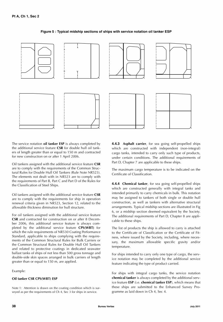
Pt A, Ch 1, Sec 2
Figure 5 : Typical midship sections of ships with service notation oil tanker ESP
The service notation oil tanker ESP is always completed bythe additional service feature CSR for double hull oil tank-ers of length greater than or equal to 150 m and contractedfor new construction on or after 1 April 2006.
Oil tankers assigned with the additional service feature CSRare to comply with the requirements of the Common Struc-tural Rules for Double Hull Oil Tankers (Rule Note NR523).The elements not dealt with in NR523 are to comply withthe requirements of Part B, Part C and Part D of the Rules forthe Classification of Steel Ships.
Oil tankers assigned with the additional service feature CSRare to comply with the requirements for ship in operationrenewal criteria given in NR523, Section 12, related to theallowable thickness diminution for hull structure.
For oil tankers assigned with the additional service featureCSR and contracted for construction on or after 8 Decem-ber 2006, this additional service feature is always com-pleted by the additional service feature CPS(WBT) forwhich the rule requirements of NR530 Coating PerformanceStandard, applicable to ships complying with the require-ments of the Common Structural Rules for Bulk Carriers orthe Common Structural Rules for Double Hull Oil Tankersand related to protective coatings in dedicated seawaterballast tanks of ships of not less than 500 gross tonnage anddouble-side skin spaces arranged in bulk carriers of lengthgreater than or equal to 150 m, are applied.
Example:
Oil tanker CSR CPS(WBT) ESP
Note 1: Attention is drawn on the coating condition which is sur-veyed as per the requirements of Ch 4, Sec 3 for ships in service.
4.4.3 Asphalt carrier, for sea going self-propelled shipswhich are constructed with independent (non-integral)cargo tanks, intended to carry only such type of products,under certain conditions. The additional requirements ofPart D, Chapter 7 are applicable to these ships.
The maximum cargo temperature is to be indicated on theCertificate of Classification.
4.4.4 Chemical tanker, for sea going self-propelled shipswhich are constructed generally with integral tanks andintended primarily to carry chemicals in bulk. This notationmay be assigned to tankers of both single or double hullconstruction, as well as tankers with alternative structuralarrangements. Typical midship sections are illustrated in Fig6, or a midship section deemed equivalent by the Society.The additional requirements of Part D, Chapter 8 are appli-cable to these ships.
The list of products the ship is allowed to carry is attachedto the Certificate of Classification or the Certificate of Fit-ness, where issued by the Society, including, where neces-sary, the maximum allowable specific gravity and/ortemperature.
For ships intended to carry only one type of cargo, the serv-ice notation may be completed by the additional servicefeature indicating the type of product carried.
For ships with integral cargo tanks, the service notationchemical tanker is always completed by the additional serv-ice feature ESP (i.e. chemical tanker ESP), which means thatthese ships are submitted to the Enhanced Survey Pro-gramme as laid down in Ch 4, Sec 4.
38 Bureau Veritas July 2011
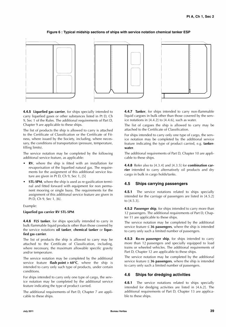
Pt A, Ch 1, Sec 2
Figure 6 : Typical midship sections of ships with service notation chemical tanker ESP
4.4.5 Liquefied gas carrier, for ships specially intended tocarry liquefied gases or other substances listed in Pt D, Ch9, Sec 1 of the Rules. The additional requirements of Part D,Chapter 9 are applicable to these ships.
The list of products the ship is allowed to carry is attachedto the Certificate of Classification or the Certificate of Fit-ness, where issued by the Society, including, where neces-sary, the conditions of transportation (pressure, temperature,filling limits).
The service notation may be completed by the followingadditional service feature, as applicable:
• RV, where the ship is fitted with an installation forrevaporisation of the liquefied natural gas. The require-ments for the assignment of this additional service fea-ture are given in Pt D, Ch 9, Sec 1, [5]
• STL-SPM, where the ship is used as re-gasification termi-nal and fitted forward with equipment for non perma-nent mooring or single buoy. The requirements for theassignment of this additional service feature are given inPt D, Ch 9, Sec 1, [6].
Example:
Liquefied gas carrier RV STL-SPM
4.4.6 FLS tanker, for ships specially intended to carry inbulk flammable liquid products other than those covered bythe service notations oil tanker, chemical tanker or lique-fied gas carrier.
The list of products the ship is allowed to carry may beattached to the Certificate of Classification, including,where necessary, the maximum allowable specific gravityand/or temperature.
The service notation may be completed by the additionalservice feature flash point > 60°C, where the ship isintended to carry only such type of products, under certainconditions.
For ships intended to carry only one type of cargo, the serv-ice notation may be completed by the additional servicefeature indicating the type of product carried.
The additional requirements of Part D, Chapter 7 are appli-cable to these ships.
4.4.7 Tanker, for ships intended to carry non-flammableliquid cargoes in bulk other than those covered by the serv-ice notations in [4.4.2] to [4.4.6], such as water.The list of cargoes the ship is allowed to carry may beattached to the Certificate of Classification.
For ships intended to carry only one type of cargo, the serv-ice notation may be completed by the additional servicefeature indicating the type of product carried, e.g. tanker-water.
The additional requirements of Part D, Chapter 10 are appli-cable to these ships.
4.4.8 Refer also to [4.3.4] and [4.3.5] for combination car-rier intended to carry alternatively oil products and drycargo in bulk in cargo holds/tanks.
4.5 Ships carrying passengers
4.5.1 The service notations related to ships speciallyintended for the carriage of passengers are listed in [4.5.2]to [4.5.3].
4.5.2 Passenger ship, for ships intended to carry more than12 passengers. The additional requirements of Part D, Chap-ter 11 are applicable to these ships.The service notation may be completed by the additionalservice feature ≤ 36 passengers, where the ship is intendedto carry only such a limited number of passengers.
4.5.3 Ro-ro passenger ship, for ships intended to carrymore than 12 passengers and specially equipped to loadtrains or wheeled vehicles. The additional requirements ofPart D, Chapter 12 are applicable to these ships.The service notation may be completed by the additionalservice feature ≤ 36 passengers, where the ship is intendedto carry only such a limited number of passengers.
4.6 Ships for dredging activities
4.6.1 The service notations related to ships speciallyintended for dredging activities are listed in [4.6.2]. Theadditional requirements of Part D, Chapter 13 are applica-ble to these ships.
July 2011 Bureau Veritas 39
Pt A, Ch 1, Sec 2
4.6.2 The following notations are provided:
a) Dredger, for ships specially equipped only for dredgingactivities (excluding carrying dredged material)
b) Hopper dredger, for ships specially equipped for dredg-ing activities and carrying spoils or dredged material
c) Hopper unit, for ships specially equipped for carryingspoils or dredged material
d) Split hopper unit, for ships specially equipped for carry-ing spoils or dredged material and which open longitu-dinally, around hinges
e) Split hopper dredger, for ships specially equipped fordredging and for carrying spoils or dredged material andwhich open longitudinally, around hinges.
4.6.3 These ships which are likely to operate at sea withinspecific limits may, under certain conditions, be granted anoperating area notation. For the definition of operating areanotation, reference should be made to [5.3].
4.7 Working ships
4.7.1 The service notations related to ships speciallyintended for different working services are listed in [4.7.2]to [4.7.6].
4.7.2 The service notations for ships intended to tow and/orpush other ships or units are:
a) Tug, for ships specially equipped for towing and/orpushing
b) Salvage tug, for ships specially equipped for towingand/or pushing having specific equipment for salvage
c) Escort tug, for ships specially equipped for towingand/or pushing having specific equipment for escortingships or units during navigation.
The additional requirements of Part D, Chapter 14 are appli-cable to these ships.
These service notations may be completed by the additionalservice feature barge combined, when units are designed tobe connected with barges and comply with the relevantrequirements of Pt D, Ch 14, Sec 3. The barges to which thetug can be connected are specified in an annex to the Cer-tificate of Classification.
4.7.3 The service notation supply vessel is assigned to shipsspecially intended for the carriage and/or storage of specialmaterial and equipment and/or which are used to providefacilities and assistance for the performance of specifiedactivities, such as offshore, research and underwater activi-ties.
The service notation is to be completed by the additionalservice feature oil product, when the ship is also speciallyintended to carry oil products having any flash point andhaving a specified maximum cargo tank capacity.
The service notation is to be completed by the additionalservice feature LHNS, for ships, other than well stimulationvessels, carrying amounts of hazardous and noxious liquidsubstances in bulk not exceeding a specified maximumvalue.
The service notation is to be completed by the additionalservice feature WS for well stimulation vessels.
The additional requirements of Part D, Chapter 15 are appli-cable to these ships.
4.7.4 The service notation fire-fighting ship is assigned toships specially intended and equipped for fighting fire. Theadditional requirements of Part D, Chapter 16 are applica-ble to these ships.
The service notation may be completed by the followingadditional service features, as applicable:
• 1 or 2 or 3, when the ship complies with the applicablerequirements of Pt D, Ch 16, Sec 3
• E, when the characteristics of the water fire-fighting sys-tem are not those required for the assignment of theadditional service features 1, 2 or 3, and when the sys-tem is specially considered by the Society
• water spraying, when the ship is fitted with a water-spraying system complying with the applicable require-ments of Pt D, Ch 16, Sec 4, [3].
4.7.5 The service notation oil recovery ship is assigned toships specially equipped with fixed installations and/ormobile equipment for the removal of oil from the sea sur-face and its retention on board, carriage and subsequentunloading. The additional requirements of Part D, Chapter17 are applicable to these ships.
4.7.6 The service notation cable laying ship is assigned toships specially equipped for the carriage and/or laying,hauling and repair of submarine cables. The additionalrequirements of Part D, Chapter 18 are applicable to theseships.
4.7.7 The service notation floating dock is assigned to float-ing docks meeting the requirements of Rule Note NR475.
Note 1: The navigation notation sheltered area is assigned to theseunits. When the dock is intended to be towed, the navigation nota-tion temporary unrestricted navigation is also to be assigned.
4.8 Non-propelled units, units with sail propulsion and other units
4.8.1 Barge
The service notation barge is assigned to non-propelledunits intended to carry (dry or liquid) cargo inside holds ortanks. The additional requirements of Part D, Chapter 19 areapplicable to these ships.
For ships intended to carry only one type of cargo, the serv-ice notation may be completed by an additional service fea-ture indicating the type of product carried e.g. barge - oil,barge - general cargo.
This service notation may be completed by the additionalservice feature tug combined when units are designed to beconnected with tugs, and comply with the relevant require-ments of Pt D, Ch 14, Sec 3. The tugs to which the bargecan be connected are specified in an annex to the Certifi-cate of Classification.
40 Bureau Veritas July 2011
Pt A, Ch 1, Sec 2
4.8.2 PontoonThe service notation pontoon is assigned to non-propelledunits intended to carry cargo and/or equipment on deckonly. When a crane is permanently fitted on board, thecrane is to be certified and the service notation pontoon -crane is granted. The additional requirements of Part D,Chapter 19 are applicable to these ships.
4.8.3 Other unitsAny non-propelled units other than those covered by theservice notations listed above will be assigned the addi-tional service feature no propulsion, to be added to theirown service notation, e.g. dredger - no propulsion.
4.8.4 Assisted propulsion unitsAny units having a propulsion system not enabling them toproceed at a speed greater than 7 knots, used for short tran-sit voyages, will be assigned the additional service featureassisted propulsion to be added to their own service nota-tion, e.g. dredger - assisted propulsion.
4.8.5 Units with a sail propulsionShips fitted with a wind propulsion plant meeting the require-ments of the Rule Note Classification of wind propulsionplants onboard ships (NR206) may have their service notationcompleted by the following additional service feature:
• WAP for an auxiliary wind propulsion
• EAWP for a wind propulsion assisted by auxiliaryengine propulsion.
4.9 Fishing vessels
4.9.1 The service notation fishing vessel is assigned to shipsspecially equipped for catching and storing fish or other liv-ing resources of the sea. The additional requirements of PartD, Chapter 20 are applicable to these ships.
The service notation may be completed by the followingadditional service feature, as applicable:
• F, when the ship complies with the requirements of PtD, Ch 20, Sec 6 related to fire prevention, ventilationsystems and means of escape
• TORRE, when the Society has verified the compliancewith the requirements for construction and equipmentof fishing vessels of the Torremolinos International Con-vention for the Safety of Fishing Vessels, as amended
• ED, when the Society has verified the compliance withthe requirements for construction and equipment offishing vessels of the European Directive 97/70/EC, asamended.
Note 1: Units solely dedicated to service in a fishing flotilla bymeans of cold storage and/or transformation of fish are not coveredby the service notation fishing vessel. They will be considered withthe service notation special service.
4.10 High Speed Crafts (HSC)
4.10.1 The high speed crafts meeting the requirements ofthe Rules for the Construction and the Classification of HighSpeed Craft (NR396 UNITAS) are assigned the followingservice notations:
• HSC-CAT A (or high speed craft-CAT A) for passengerships defined as ‘’Category A craft’’ in respect of theIMO International Code of Safety for High Speed Craft
• HSC-CAT B (or high speed craft-CAT B) for passengerships defined as ‘’Category B craft’’ in respect of theIMO International Code of Safety for High Speed Craft
• HSC (or high speed craft) for ships other than the above;in this case, the type of service may be specified afterthe notation, i.e. HSC/passenger carrier.
4.10.2 The service notation light ship is assigned to shipsmeeting the requirements of the Rules for the Constructionand the Classification of High Speed Craft (NR396 UNITAS)for the hull requirements (Chapters 3 and 6) and therequirements of the present Rules for the stability ( Part B)and for the machinery installation ( Part C).
The type of service may be specified after the notation, i.e.light ship/fast passenger vessel, light ship/fast cargo vessel.
4.11 Miscellaneous units
4.11.1 Special service
a) General
The service notation special service is assigned to shipswhich, due to the peculiar characteristics of their activ-ity, are not covered by any of the notations mentionedabove. The classification requirements of such units areconsidered by the Society on a case by case basis.
This service notation may apply, for instance, to shipsengaged in research, expeditions and survey, ships fortraining of marine personnel, whale and fish factoryships not engaged in catching, ships processing otherliving resources of the sea, and other ships with designfeatures and modes of operation which may be referredto the same group of ships.
An additional service feature may be specified after thenotation (e.g. special service-training, special service-fish factory, special service-standby rescue vessel) toidentify the particular service in which the ship isintended to trade. The scope and criteria of classifica-tion of such units are indicated in an annex to the Certif-icate of Classification.
b) Special service - standby rescue vessel
Ships complying with the requirements of Rule NoteNR482 are eligible for the assignment of the servicenotation special service - standby rescue vessel.
This service notation may be completed by the numberof survivors that the vessel is intended to carry. Depend-ing on the vessel operation area, the Society may adaptthe requirements regarding the survivors accommoda-tion and/or the safety equipment. In such a case, thisservice notation is to be completed by the number ofsurvivors that the vessel is intended to carry and by thevessel operation area, as for example: special service -standby rescue vessel (150 survivors, Guinea Gulf).
July 2011 Bureau Veritas 41

Pt A, Ch 1, Sec 2
4.11.2 Launch
The launches or motorboats with a length not exceeding24m and meeting the requirements of Part D, Chapter 21are assigned the following service notations:
• seagoing launch, for units intended for seagoing service,limited at a wind force not exceeding 6 Beaufort scale
• launch, for units intended for operation in ports, road-steads, bays and generally calm stretches of water, lim-ited at a wind force not exceeding 4 Beaufort scale.
Note 1: Ships that are assigned the service notation launch or sea-going launch are not assigned a navigation notation.
4.11.3 Yacht and charter yacht
The service notation charter yacht is assigned to shipsintended for pleasure cruising, engaged in commercial sail-ing and complying with the applicable requirements of RuleNote NR500.
The service notation yacht is assigned to ships intended forpleasure cruising other than charter yacht and complyingwith the applicable requirements of Rule Note NR500.Ships assigned with the service notation yacht and having alength less than 24 m are not submitted to annual surveysfor hull and machinery.
The service notation yacht or charter yacht is always com-pleted by one of the following additional service features, asapplicable:
• motor for units propelled by propulsion engine
• sailing for units with a sail propulsion, including thoseassisted by auxiliary propulsion engine.
Examples:
yacht-motor
yacht-sailing
charter yacht-motor
charter yacht-sailing
The service notation yacht or charter yacht is completed bythe additional service feature S when the hull is made ofsteel material.
Example:
yacht-motor-S
When the hull is made of other material, additional servicefeatures are to be assigned in accordance with the require-ments of Rule Note NR500.
Ships with service notation yacht or charter yacht areassigned a navigation notation as listed in [5.2], except forthe navigation notations summer zone and tropical zonewhich are not assigned.
For high speed motor yachts meeting the requirements ofRule Note NR500, Pt B, Ch 5, Sec 1, [2], the followingapplies:
• As a rule, the navigation notation assigned to such unitis corresponding to sea areas where the significant waveheight H.S. is not to exceed for more than 10 per cent ofthe year the following values:
- sheltered area: 0,5 m
- coastal area: 2,5 m
- unrestricted navigation: no limitation.
• The table of the speed relative to the sea states, charac-terised by their significant wave height, is annexed tothe Certificate of Classification.
4.11.4 Crew boats
The service notation crew boat is assigned to ships less than500 GT, of length not greater than 45 m, dedicated to trans-port of offshore personnel from harbours to moored offshoreinstallations or ships and meeting the requirements of RuleNote NR490.
Note 1: Ships which do not fulfil the minimum speed criteria inSection 1, [1.1.1] of NR490 will not be assigned the above servicenotation.
4.11.5 Compressed natural gas carrier
The service notation compressed natural gas carrier isassigned to ships intended to carry compressed natural gas(CNG) meeting the requirements of NR517 Classification ofCompressed Natural Gas Carriers.
4.11.6 Other units
For ships or other floating units intended to be classed withother service notations, reference is to be made to the spe-cific Rules of the Society, and in particular:
• Rules and Regulations for the Construction and Classifi-cation of Wooden Fishing Vessels (NR219)
• Rules for the Classification of Offshore Units (NR445)
• Rules and Regulations for the Classification of Submers-ibles (NR316).
4.11.7 Inland navigation vessels
For ships and units intended for navigation in inland waters,reference is to be made to the Rules and Regulations for theConstruction and Classification of Inland Navigation Ves-sels (NR217).
4.12 Ships with gas fuelled propulsion
4.12.1 The service notation is completed by one of the fol-lowing additional service features, when the ship complieswith the requirements of NR529 Safety Rules for Gas-Fuelled Engine Installations in Ships, for internal combus-tion engines using gas as fuel, as applicable:
• dualfuel for engines using both gas and fuel oil as fuel
• gasfuel for engines using only gas as fuel.
The gas may be either compressed natural gas or liquefiednatural gas.
42 Bureau Veritas July 2011
Pt A, Ch 1, Sec 2
4.13 Icebreaker ships
4.13.1 The service notation Icebreaker is assigned to shipshaving an operational profile that includes escort or icemanagement functions, having powering and dimensionsthat allow them to undertake independent operations in icecovered waters.
The service notations dealt with under [4.13.2] are relevantto ships intended for navigation in ice-infested polar waters.
The requirements for the assignment of these service nota-tions are given in Rule Note NR527 Rules for the Classifica-tion of POLAR CLASS and ICEBREAKER Ships.
Ships complying with the requirements of Rule Note NR527and assigned with one of the additional service notationsIcebreaker are also to comply with the requirements for theassignment of the additional class notation defined in[6.14.12]: COLD (H tDH , E tDE).
4.13.2 The following service notations are assigned:
• Icebreaker 1 for summer/autumn operations withoutrestrictions and for winter/spring operations in multi-year ice with 3,0 m max ice thickness
• Icebreaker 2 for summer/autumn operations in multi-year ice with 3,0 m max ice thickness and for win-ter/spring operations in second-year ice with 2,5 m maxice thickness.
• Icebreaker 3 for summer/autumn operations in second-year ice with 2,5 m max ice thickness and for win-ter/spring operations in thick first-year ice with 1,8 mmax ice thickness
• Icebreaker 4 for summer/autumn operations in thickfirst-year ice with 1,8 m max ice thickness and for win-ter/spring operations in medium first-year ice with 1,2 mmax ice thickness
• Icebreaker 5 for summer/autumn operations in mediumfirst-year ice with 1,2 m max ice thickness and for win-ter/spring operations in medium first-year ice with 1,0 mmax ice thickness
• Icebreaker 6 for summer/autumn operations in mediumfirst-year ice with 1,0 m max ice thickness and for win-ter/spring operations in medium first-year ice with 0,8 mmax ice thickness
• Icebreaker 7 for summer/autumn operations in mediumfirst-year ice with 0,8 m max ice thickness and for win-ter/spring operations in thin first-year ice with 0,6 mmax ice thickness.
5 Navigation and operating area notations
5.1 Navigation notations
5.1.1 Every classed ship is to be assigned one navigationnotation as listed in [5.2], except those with the servicenotations launch or seagoing launch.
5.1.2 The assignment of a navigation notation, includingthe reduction of scantlings or specific arrangements forrestricted navigation notations, is subject to compliancewith the requirements laid down in Part B, Part C and Part Dof the Rules and in NR216 Materials and Welding.
5.1.3 The assignment of a navigation notation does notabsolve the Interested Party from compliance with any inter-national and national regulations established by the Admin-istrations for a ship operating in national waters, or aspecific area, or a navigation zone. Neither does it waivethe requirements in Ch 1, Sec 1, [3.3.1].
5.2 List of navigation notations
5.2.1 The navigation notation unrestricted navigation isassigned to a ship intended to operate in any area and anyperiod of the year.
5.2.2 The navigation notation summer zone is assigned toships intended to operate only within the geographical lim-its as defined in ILLC 1966 for the Summer zones.
5.2.3 The navigation notation tropical zone is assigned toships intended to operate only within the geographical lim-its as defined in ILLC 1966 for the Tropical zones.
5.2.4 The navigation notation coastal area is assigned toships intended to operate only within 20 nautical milesfrom the shore and with a maximum sailing time of sixhours from a port of refuge or safe sheltered anchorage.
5.2.5 The navigation notation sheltered area is assigned toships intended to operate in sheltered waters, i.e. harbours,estuaries, roadsteads, bays, lagoons and generally calmstretches of water and when the wind force does not exceed6 Beaufort scale.
5.2.6 In specific cases, the designation of the geographicalarea and/or the most unfavourable sea conditions consid-ered may be added to the navigation notation.
5.2.7 The navigation notation temporary unrestricted navi-gation may be assigned, in addition to the navigation nota-tions defined in [5.2.2], [5.2.3], [5.2.4] or [5.2.5] to serviceships for which the period of unrestricted navigation may bechosen to satisfy the conditions defined in an annex to theCertificate of Classification.
When a favourable weather situation is included amongstthese conditions, the voyages are to be such as the ship canbe put in a port or a sheltered anchorage in about 12 hoursfrom any point of its route.
Note 1: Before any voyage covered by the navigation notation tem-porary unrestricted navigation, the ship is to be submitted to anoccasional survey, during which the Surveyor checks that theintended voyage and the ship’s specific condition, if any, complywith the conditions defined in the annex to the Certificate of Classi-fication.
July 2011 Bureau Veritas 43
Pt A, Ch 1, Sec 2
5.2.8 For ships assigned with the service notation:• HSC-CAT A, HSC-CAT B, or HSC as defined in [4.10.1],• light ship, as defined in [4.10.2], or• crew boat, as defined in [4.11.4],
as a rule, one of the following navigation notations is to beassigned to such units and is corresponding to sea areaswhere the significant wave height H.S. is not to exceed formore than 10 per cent of the year the following values:• sea area 1: 0,5 m• sea area 2: 2,5 m• sea area 3: 4,0 m• sea area 4: no limitation.
The shipyard’s table of the maximum allowed ship speedrelative to the sea states, characterised by their significantwave height, is annexed to the Certificate of Classification.
5.3 Operating area notations
5.3.1 The operating area notation expresses the specifiedarea where some service units are likely to operate at seawithin specific restrictions which are different from normalnavigation conditions. The operating area notation is, in principle, solely grantedto ships for dredging activities.
This operating area notation is indicated after the navigationnotation.
Example: unrestricted navigation - “operating area notation”
5.3.2 The following operating area notations may beassigned:• dredging within 8 miles from shore,• dredging within 15 miles from shore or within 20 miles
from port,• dredging over 15 miles from shore.
The operating area of the first two categories as specified in[4.6] may be extended respectively over 8 or 15 miles. Inthat case, the operating area notation is completed by themaximum significant wave height during service, as follows:
dredging over 8 (or 15) miles from shore with H.S. ≤ ... m.
For ships being assigned the service notation split hopperunit or split hopper dredger, the operating area notationmay be completed by the maximum allowable significantheight of waves during the service, being indicated betweenparenthesis, i.e. (H.S. ≤ ... m).
6 Additional class notations
6.1 General
6.1.1 An additional class notation expresses the classifica-tion of additional equipment or specific arrangement,which has been requested by the Interested Party.
6.1.2 The assignment of such an additional class notation issubject to the compliance with additional rule require-ments, which are detailed in Part E of the Rules.
6.1.3 Some additional class notations are assigned a con-struction mark, according to the principles given in [3.1.2].This is indicated in the definition of the relevant additionalclass notations.
6.1.4 The different additional class notations which may beassigned to a ship are listed in [6.2] to [6.15], according tothe category to which they belong. These additional classnotations are also listed in alphabetical order in Tab 2.
6.2 VeriSTAR and STAR notations
6.2.1 GeneralVeriSTAR and STAR notations integrate rational analysis atdesign stage or after construction and possibly with dataand records from ships-in-service concerning plannedinspection and ship maintenance.
In compliance with [6.1.3], these notations are assigned aconstruction mark, as defined in [3].
The requirements for the assignment of these notations aregiven in Part E, Chapter 1.
Table 2 : List of additional class notations
Additional class notation Definition in Reference in NR 467 or to other Rule Notes Remarks
ALPALMALS(ALP)(ALM)(ALS)
(1) (1) (1) (1) (1) (1)
[6.12] Rule Note NR 526 for derricks including heavy derricks and derricks inunion purchase, see Rule Note NR 184
AUT-CCS (1) [6.4.3] Pt E, Ch 3, Sec 2
AUT-IMS (1) [6.4.5] Pt E, Ch 3, Sec 4
AUT-PORT (1) [6.4.4] Pt E, Ch 3, Sec 3
AUT-UMS (1) [6.4.2] Pt E, Ch 3, Sec 1
AVM-APS (1) [6.3.2] Pt E, Ch 2, Sec 1 AVM-DPS and AVM-IPS may be completed by theadditional suffix /NSAVM-DPS (1) [6.3.3] Pt E, Ch 2, Sec 2
AVM-IPS (1) [6.3.4] Pt E, Ch 2, Sec 3
44 Bureau Veritas July 2011

Pt A, Ch 1, Sec 2
AWT [6.8.4] Part E, Chapter 9
BWE [6.8.5] Part E, Chapter 9
BWT [6.8.6] Part E, Chapter 9
CARGOCONTROL [6.14.9] Pt E, Ch 10, Sec 9
CLEANSHIP [6.8.2] Part E, Chapter 9
CLEANSHIP SUPER ( ) [6.8.3] between brackets, at least 3 eligible notations are to be assigned among the following ones: AWT, BWT, GWT, HVSC, NDO -x days, NOX-x%, OWS-x ppm, SOX-x%
COLD (H tDH, E tDE) [6.14.12] Pt E, Ch 10, Sec 11
COMF+ [6.7.4] Part E, Chapter 6 COMF+ is to be completed by the selected perform-ance indexes (Sound insulation index/ Impact index/Emergence/ Intermittent noise/ Intelligibility)grade y is equal to 1, 2, or 3grade y’ is equal to 1, 2, 3, 1PK, 2PK or 3PK
COMF-NOISE y [6.7.2]
COMF-VIB y’ [6.7.3]
COMF-NOISE-Crew yCOMF-NOISE-Pax yCOMF-VIB-Crew y’COMF-VIB-Pax y’
[6.7.5]
COVENT [6.14.8] Pt E, Ch 10, Sec 8
CPS(WBT) [6.15.4] Rule Note NR 530 on a voluntary basis for ships other than bulk carriersCSR or oil tankers CSR contracted for constructionon or after 8 December 2006
DYNAPOS SAMDYNAPOS AMDYNAPOS ATDYNAPOS AM/AT
(1) (1) (1) (1)
[6.14.6] Pt E, Ch 10, Sec 6 DYNAPOS AM and DYNAPOS AT may be com-pleted by R or RS DYNAPOS AM/AT may be completed by R or RS or(xx ; xx) (corresponding to the two-number vectorfor the Environmental Station Keeping Index ESKI)
EFP-AEFP-MEFP-CEFP-AMC
[6.14.17] Pt E, Ch 10, Sec 15
ERS-HERS-MERS-S
[6.13.2] Rule Note NR 556
ETA [6.15.3] Pt B, Ch 10, Sec 4, [4]
EWCT [6.14.14] Pt E, Ch 10, Sec 12
Fatigue PLUSFatigue PLUS DFL xxFatigue PLUS spectral ( )Fatigue PLUS spectral ( ) DFL xx
[6.14.18] Rule Note NR 552 xx is given in years, with xx > 25between brackets: short description of the route orareas encountered by the ship during its service life
FORS [6.14.19] Rule Note NR 553 this notation may be completed by the notation -NS
GRAB [X] [6.14.2] Rule Note NR 522, Ch 12 on a voluntary basis for bulk carriers other than CSRBC-A or CSR BC-B
GRABLOADING [6.14.2] b) Pt E, Ch 10, Sec 2
GREEN PASSPORT [6.14.13] Rule Note NR 528
GWT [6.8.7] Part E, Chapter 9
HVSC [6.14.20] Rule Note NR 557
IATP [6.14.16] Pt E, Ch 10, Sec 14
Additional class notation Definition in Reference in NR 467 or to other Rule Notes Remarks
July 2011 Bureau Veritas 45

Pt A, Ch 1, Sec 2
ICE [6.10.4] Part E, Chapter 8
ICE CLASS IA SUPERICE CLASS IAICE CLASS IBICE CLASS IC
[6.10.2]
ICE CLASS ID [6.10.3]
IG [6.15.2] Pt D, Ch 7, Sec 6 and Pt D, Ch 8, Sec 9
INWATERSURVEY [6.14.3] Pt E, Ch 10, Sec 3
LASHING [6.14.5] Pt E, Ch 10, Sec 5
MANOVR [6.14.10] Pt E, Ch 10, Sec 10 IMO Resolution MSC 137(76)
MON-HULL [6.6.2] Pt E, Ch 5, Sec 1
MON-SHAFT [6.6.3] Pt E, Ch 5, Sec 2
NDO-x days [6.8.8] Part E, Chapter 9
NOX-x% [6.8.9] Part E, Chapter 9
OWS-x ppm [6.8.10] Part E, Chapter 9
POLAR CLASS z [6.11] Rule Note NR 527 z is equal to 1, 2, 3, 4, 5, 6 or 7
PROTECTED FO TANK [6.14.15] Pt E, Ch 10, Sec 13
REF-CARGO (1) [6.9.2] Pt E, Ch 7, Sec 2 this notation may be completed by the specific nota-tions -AIRCONT, -PRECOOLING and/or -QUICK-FREEZE
REF-CONT (A)REF-CONT (E)
(1) [6.9.3] Pt E, Ch 7, Sec 3 these notations may be completed by the specificnotations -PRECOOLING and/or -QUICKFREEZEREF-CONT (A) may be completed by the specificnotation -AIRCONT
REF-STORE (1) [6.9.4] Pt E, Ch 7, Sec 4 this notation may be completed by the specific nota-tions -PRECOOLING and/or -QUICKFREEZE
SDS [6.14.11] Pt B, Ch 3, Sec 3
SINGLEPASSLOADING [6.14.21] Pt E, Ch 10, Sec 16 this additional class notation may be completed bythe design loading rate in tons per hour, for example:SINGLEPASSLOADING [xxxxx t/h]
SOX-x% [6.8.11] Part E, Chapter 9 as an alternative, equivalent arrangements (e.g. exhaust gas cleaning systems) may be accepted
SPM [6.14.4] Pt E, Ch 10, Sec 4
STAR SIS (1) [6.2.7] the cumulative notation STAR SIS supersedes thenotations STAR-HULL and STAR-MACH SISSTAR-HULL (1) [6.2.4] Pt E, Ch 1, Sec 2
STAR-MACH (1) [6.2.6] Pt E, Ch 1, Sec 3
STAR-MACH SIS (1) [6.2.5]
STRENGTHBOTTOM [6.14.1] Pt E, Ch 10, Sec 1
SYS-COM (1) [6.5.4] Pt E, Ch 4, Sec 3 SYS-COM can only be assigned to ships which arealso assigned the notation AUT-IMSSYS-IBS can only be assigned to ships which are also assigned the notation SYS-NEQSYS-IBS-1 can only be assigned to ships which arealso assigned the notations SYS-NEQ-1 and AUT-UMS
SYS-IBS
SYS-IBS-1
(1) [6.5.3] Pt E, Ch 4, Sec 2
SYS-NEQSYS-NEQ-1
(1) [6.5.2] Pt E, Ch 4, Sec 1
VCS [6.14.7] Pt E, Ch 10, Sec 7 this notation may be completed by the specific nota-tion -TRANSFER (see [6.14.7])
VeriSTAR-HULL (1) [6.2.2] Pt E, Ch 1, Sec 1 these notations may be completed by DFL xx years,with 25 ≤ xx ≤ 40VeriSTAR-HULL SIS (1) [6.2.3]
(1) A construction mark is added to this notation.
Additional class notation Definition in Reference in NR 467 or to other Rule Notes Remarks
46 Bureau Veritas July 2011

Pt A, Ch 1, Sec 2
6.2.2 VeriSTAR-HULL
The additional class notation VeriSTAR-HULL is assigned toships the structural condition of which is checked with 3DFEM calculation programme at design stage or after con-struction, according to the requirements of the Society.
VeriSTAR-HULL encompass the fatigue assessment carriedout on selected structural details as per the requirements ofPart B.
The requirements for the assignment of this notation aregiven in Pt E, Ch 1, Sec 1.
The additional class notation VeriSTAR-HULL may be com-pleted by DFL xx years, with xx having values between 25and 40, when a fatigue assessment has been carried out onselected structural details showing that their evaluateddesign fatigue life is not less than xx years.
The requirements for the assignment of DFL xx years aregiven in Pt E, Ch 1, Sec 1 and Pt B, Ch 7, Sec 4, as relevant.
The additional class notations VeriSTAR-HULL and VeriS-TAR-HULL DFL xx years may be assigned to ships of lessthan 170 m in length, subject to special consideration bythe Society.
6.2.3 VeriSTAR-HULL SIS
The additional class notation VeriSTAR-HULL may be com-pleted by SIS for ships the structural condition of which isreassessed using survey data.
The requirements for the assignment and maintenance ofthis notation are given respectively in Pt E, Ch 1, Sec 1 andin Ch 5, Sec 2.
This notation is not applicable to ships assigned with theadditional service feature CSR.
This notation may be completed by DFL xx years as detailedin [6.2.2].
6.2.4 STAR-HULL
The additional class notation STAR-HULL is assigned toships for which, in addition to the requirements for assign-ment of the additional class notation VeriSTAR-HULL SIS,an Inspection and Maintenance Plan for the hull is imple-mented by the Owner.
This notation is not applicable to ships assigned with theadditional service feature CSR.
The requirements for the assignment and maintenance ofthis notation are given respectively in Pt E, Ch 1, Sec 2 andin Ch 5, Sec 2.
6.2.5 STAR-MACH SIS
The additional class notation STAR-MACH SIS is assigned toships on which a Planned Maintenance Survey System formachinery (PMS) is implemented as per the requirements ofCh 2, Sec 2, [4.4]. In addition, the notation STAR-MACHSIS includes a risk analysis update of the ship's machineryand other equipment (navigation instrumentation, anchor-ing and mooring arrangements, ...).
The requirements for the assignment and maintenance ofthis notation are given respectively in Pt E, Ch 1, Sec 3 andin Ch 5, Sec 2.
6.2.6 STAR-MACH
The additional class notation STAR-MACH is assigned toships subject to compliance with the requirements for theassignment of the notation and for which the requirementsfor maintenance of the notation given in Ch 5, Sec 2 are notapplied.
The requirements for the assignment of this notation aregiven in Pt E, Ch 1, Sec 3.
6.2.7 STAR SIS
When ships are assigned the notations STAR-HULL andSTAR-MACH SIS, the two separate notations are supersededby the cumulative additional class notation STAR SIS.
6.3 Availability of machinery (AVM)
6.3.1 General
The notations dealt with under this heading are relevant tosystems and/or arrangements enabling the ship to carry onlimited operations when single failure affects propulsion orauxiliary machinery or when an external event such as fireor flooding involving machinery spaces affects the availabil-ity of the machinery.
In compliance with [6.1.3], these notations are assigned aconstruction mark, as defined in [3].
The requirements for the assignment of these notations aregiven in Part E, Chapter 2.
6.3.2 Alternative propulsion system (AVM-APS)
The additional class notation AVM-APS is assigned to shipswhich are fitted with systems and/or arrangements enablingthem to maintain operating conditions with some limitationsin speed, range and comfort, in the case of single failure ofitems relative to the propulsion or power generating system.
The limitations in operation and the types of single failurecovered by this notation are specified in Pt E, Ch 2, Sec 1,[1.2].
6.3.3 Duplicated propulsion system (AVM-DPS)
The additional class notation AVM-DPS is assigned to shipswhich are fitted with a duplicated propulsion system ena-bling them to maintain operating conditions with some lim-itations in power (but 50% of the main power is to bemaintained), speed, range and comfort, in the case of singlefailure of items relative to the propulsion or power generat-ing system.
The limitations in operation and the types of failure whichare covered by this notation are specified in Pt E, Ch 2, Sec2, [1.2].
The additional suffix NS may be added to the notation whenthe ship is intended for normal operation with one propul-sion system out of service in accordance with the provisionsof Pt E, Ch 2, Sec 2, [4].
Note 1: The loss of one compartment due to fire or flooding is notconsidered as a single failure case.
July 2011 Bureau Veritas 47
Pt A, Ch 1, Sec 2
6.3.4 Independent propulsion system (AVM-IPS)
The additional class notation AVM-IPS is assigned to shipswhich are fitted with an independent propulsion systemenabling them to maintain operating conditions with somelimitations in power (but 50% of the main power is to bemaintained), speed, range and comfort, in the case of singlefailure of items relative to the propulsion or power generat-ing system.
The limitations in operation and the types of failure whichare covered by this notation are specified in Pt E, Ch 2, Sec3, [1.2].
The additional suffix NS may be added to the notation whenthe ship is intended for normal operation with one propul-sion system out of service in accordance with the provisionsof Pt E, Ch 2, Sec 3, [4].
Note 1: The loss of one compartment due to fire or flooding is con-sidered as a single failure case.
6.4 Automated machinery systems (AUT)
6.4.1 General
The notations dealt with under this heading are relevant toautomated machinery systems installed on board ships.
In compliance with [6.1.3], these notations are assigned aconstruction mark, as defined in [3].
The requirements for the assignment of these notations aregiven in Part E, Chapter 3.
6.4.2 Unattended machinery space (AUT-UMS)
The additional class notation AUT-UMS is assigned to shipswhich are fitted with automated installations enablingmachinery spaces to remain periodically unattended in allsailing conditions including manoeuvring.
6.4.3 Centralised control station (AUT-CCS)
The additional class notation AUT-CCS is assigned to shipswhich are fitted with machinery installations operated andmonitored from a centralised control station.
6.4.4 Automated operation in port (AUT-PORT)
The additional class notation AUT-PORT is assigned to shipswhich are fitted with automated installations enabling theship’s operation in port or at anchor without personnel spe-cially assigned for the watch-keeping of the machinery inservice.
6.4.5 Integrated machinery system (AUT-IMS)
The additional class notation AUT-IMS is assigned to shipswhich are fitted with automated installations enablingmachinery spaces to remain periodically unattended in allsailing conditions including manoeuvring, and additionallyprovided with integrated systems enabling to handle con-trol, safety and monitoring of machinery.
6.5 Integrated ship systems (SYS)
6.5.1 General
The notations dealt with under this heading are relevant tooperation of integrated systems regarding navigation,machinery, communication and specific cargo, as applica-ble.
In compliance with [6.1.3], these notations are assigned aconstruction mark, as defined in [3].
The requirements for the assignment of these notations aregiven in Part E, Chapter 4.
6.5.2 Centralised navigation equipment (SYS-NEQ and SYS-NEQ-1)
The additional class notation SYS-NEQ is assigned to shipswhich are fitted with a centralised navigation control systemso laid out and arranged that it enables normal navigationand manoeuvring operation of the ship by two persons incooperation.
The additional class notation SYS-NEQ-1 is assigned when,in addition to the above, the installation is so arranged thatthe navigation and manoeuvring of the ship can be operatedunder normal conditions by one person, for periodical oneman watch. This notation includes specific requirements forprevention of accidents caused by the operator’s unfitness.
6.5.3 Integrated bridge system (SYS-IBS andSYS-IBS-1)
The additional class notation SYS-IBS is assigned to shipsfitted with an integrated bridge system which allows simpli-fied and centralised bridge operation of the main functionsof navigation, manoeuvring and communication, as well asmonitoring from bridge of other functions related to passageexecution, route control and monitoring and control andmonitoring of machinery installation according to Part C,Chapter 3.
The notation SYS-IBS is assigned only to ships which arealso assigned the additional class notation SYS-NEQ.
The additional class notation SYS-IBS-1 is assigned to shipsfitted with an integrated bridge system which allows simpli-fied and centralised bridge operation of the main functionsof navigation, manoeuvring and communication, as well asmonitoring from bridge of other functions related to passageexecution, route control and monitoring and control andmonitoring of machinery installation according to Part C,Chapter 3 and Pt E, Ch 3, Sec 1 (AUT-UMS notation).
In addition, the following functions may be part of the nota-tion SYS-IBS-1:
• external / internal communication system
• monitoring of specific cargo operations
• pollution monitoring
• monitoring of heating, ventilation and air conditioningfor passenger ships.
The notation SYS -IBS-1 is assigned only to ships which arealso assigned the additional class notation SYS-NEQ-1.
48 Bureau Veritas July 2011
Pt A, Ch 1, Sec 2
6.5.4 Communication system (SYS-COM)
The additional class notation SYS-COM is assigned to shipswhich are fitted with a local area network including thealarm, monitoring and control systems and computers usedfor management operations and external communicationdevices for reporting ashore navigation, maintenance andoperational information.
The notation SYS-COM is assigned only to ships which arealso assigned the additional class notation AUT-IMS.
6.6 Monitoring equipment (MON)
6.6.1 General
The notations dealt with under this heading are relevant tohull and tailshaft monitoring equipment installed on boardships.
The requirements for the assignment of these notations aregiven in Part E, Chapter 5.
6.6.2 Hull stress monitoring (MON-HULL)
The additional class notation MON-HULL is assigned toships which are fitted with equipment continuously moni-toring ship’s dynamic loads through measurements ofmotions in waves and stresses/deformations in the hullstructure.
6.6.3 Tailshaft monitoring system (MON-SHAFT)
The additional class notation MON-SHAFT is assigned toships which are fitted with a temperature monitoring systemfor the tailshaft sterntube aft bearing. The assignment of thisnotation allows the ship to be granted a reduced scope forcomplete tailshaft surveys, see Ch 2, Sec 2, [5.5.4].
6.7 Comfort on board ships (COMF)
6.7.1 General
The notations dealt with under this heading are relevant tothe assessment of comfort on board ships with regard to thenoise and/or vibration.
The parameters which are taken into consideration for theevaluation of the comfort such as the level of noise, thelevel of vibration will be indicated in the relevant annex tothe Certificate of Classification.
The requirements for the assignment of these notations aregiven in Part E, Chapter 6.
6.7.2 Comfort with regard to noise (COMF-NOISE)
The additional class notation COMF-NOISE is assigned toships satisfying levels of noise defined in Part E, Chapter 6.The assessment of noise levels is carried out through meas-urements during harbour and sea trials.
The notation is completed by a grade 1, 2 or 3 which repre-sents the comfort level achieved for the assignment of thenotation. The lower grade (1) corresponds to the higherclass of comfort.
Example:
COMF-NOISE 2
6.7.3 Comfort with regard to vibration (COMF-VIB)
The additional class notation COMF-VIB is assigned toships satisfying levels of vibration defined in Part E, Chapter6. The assessment of vibration is carried out through meas-urements during harbour and sea trials.
The notation is completed by a grade:
• 1, 2 or 3 for an evaluation based on overall frequencycriteria, or
• 1PK, 2PK or 3PK for an evaluation based on singleamplitude peak criteria.
The grade represents the comfort level achieved for theassignment of the notation. The lower grade (1 or 1PK) cor-responds to the higher class of comfort.
Example:
COMF-VIB 1PK
6.7.4 High comfort level with regard to noise (COMF+)
The additional class notation COMF+ is assigned to yachtssatisfying levels of noise defined in Pt E, Ch 6, Sec 5.
The requirements of notations COMF-NOISE have to be ful-filled prior to assigning the notation COMF+.
This notation COMF+ deals with additional criteria in viewto evaluate higher standard comfort level than COMF-NOISE. These additional criteria are to be selected amongthe following performance indexes:
• Sound insulation index
• Impact index
• Emergence
• Intermittent noise
• Intelligibility.
The additional class notation COMF+ is to be completed bythe selected performance indexes.
Example:
COMF + /Impact index /Intermittent noise /Intelligibility
This notation is assigned only to ships having the servicenotation yacht or charter yacht.
Note 1: The additional class notation COMF+ may also be appliedto ships assigned with the service notation Passenger ship after spe-cial consideration.
6.7.5 Comfort for passenger and crew areas
The additional class notations COMF-NOISE-Pax, COMF-NOISE-Crew, followed by grade 1, 2 or 3 and COMF-VIB-Pax and COMF-VIB-Crew, followed by grade 1, 2 or 3 or1PK, 2PK or 3PK are assigned to ships satisfying levels ofnoise / vibration defined in Part E, Chapter 6, for passengeror crew area, as applicable.
Example:
COMF-VIB-Crew 3
July 2011 Bureau Veritas 49

Pt A, Ch 1, Sec 2
6.8 Pollution prevention
6.8.1 GeneralThe notations dealt with under this heading are assigned toships fitted with equipment and arrangements enablingthem to control and limit the emission of polluting sub-stances in the sea and the air.
The requirements for the assignment of these notations aregiven in Part E, Chapter 9.
6.8.2 Pollution prevention (CLEANSHIP)The additional class notation CLEANSHIP is assigned toships so designed and equipped as to control and limit theemission of polluting substances in the sea and the air inaccordance with the provisions of Pt E, Ch 9, Sec 1 and PtE, Ch 9, Sec 2.
6.8.3 Pollution prevention (CLEANSHIP SUPER)The additional class notation CLEANSHIP SUPER isassigned to ships so designed and equipped as to controland limit the emission of polluting substances in the sea andthe air in accordance with the provisions of Pt E, Ch 9, Sec1 and Pt E, Ch 9, Sec 2.Note 1: At least 3 eligible notations are to be assigned among thefollowing ones:
AWT, BWT, GWT, HVSC, NDO-x days, NOX-x%, OWS-x ppm,SOX-x%.
Example:
CLEANSHIP SUPER (AWT, NOX-80%, SOX-60%)
6.8.4 Advanced Wastewater Treatment (AWT)The additional class notations AWT is assigned to ships fit-ted with an Advanced Wastewater Treatment plant inaccordance with the provisions of Pt E, Ch 9, Sec 1 and PtE, Ch 9, Sec 3.
6.8.5 Ballast Water Exchange (BWE)The additional class notation BWE is assigned to shipsdesigned for ballast water exchange complying with therequirements of BWM convention (2004) and in accord-ance with the provisions of Pt E, Ch 9, Sec 1 and Pt E, Ch 9,Sec 3.
6.8.6 Ballast Water Treatment (BWT)The additional class notation BWT is assigned to ships fittedwith a Ballast Water Treatment plant in accordance with theprovisions of Pt E, Ch 9, Sec 1 and Pt E, Ch 9, Sec 3.
6.8.7 Grey Water Treatment (GWT)The additional class notation GWT is assigned to ships fittedwith a treatment installation for grey waters in accordancewith the provisions of Pt E, Ch 9, Sec 1 and Pt E, Ch 9, Sec 3.
6.8.8 No Discharge Operation (NDO-x days)The additional class notation NDO-x days is assigned toships designed for no discharge operation during x days, inaccordance with the provisions of Pt E, Ch 9, Sec 1 and PtE, Ch 9, Sec 3. Note 1: x days is the number of consecutive days the ship is able tooperate with the full complement of on-board people, includingcrew and passengers, without the need for discharging any sub-stances into the sea. This number cannot be less than one day
(24 hours).
6.8.9 NOx emissions control (NOX-x%)The additional class notation NOX-x% is assigned to shipsfor which the average NOx emissions of engines are not toexceed x% of IMO Tier II limit in accordance with the pro-visions of Pt E, Ch 9, Sec 1 and Pt E, Ch 9, Sec 3.
6.8.10 High-performance Oily Water Separator (OWS-x ppm)
The additional class notation OWS-x ppm is assigned toships fitted with an oily water separator producing effluentshaving a hydrocarbon content not exceeding x ppm (partsper million) in accordance with the provisions of Pt E, Ch 9,Sec 1 and Pt E, Ch 9, Sec 3.
6.8.11 SOx emissions control (SOX-x%)The additional class notation SOX-x% is assigned to shipsfor which the oil fuels used within and outside SECAs havea sulphur content not exceeding x% of the relevant IMOlimit in accordance with the provisions of Pt E, Ch 9, Sec 1and Pt E, Ch 9, Sec 3.
Note 1: As an alternative, equivalent arrangements (e.g. exhaustgas cleaning systems) may be accepted.
6.9 Refrigerating installations
6.9.1 GeneralThe notations dealt with under this heading are relevant torefrigerating installations fitted on board ships, includingmachinery and storing equipment or arrangements.
In compliance with [6.1.3], these notations are assigned aconstruction mark, as defined in [3].
The requirements for the assignment of these notations aregiven in Part E, Chapter 7.
6.9.2 Refrigerating installations for cargo(REF-CARGO)
The additional class notation REF-CARGO is assigned toships fitted with refrigerating plants and holds intended tocarry cargoes, with the condition that the number and thepower of the refrigerating units are such that the specifiedtemperatures can be maintained with one unit on standby.
The notation -AIRCONT is added when the refrigeratingplant is equipped with controlled atmosphere installations.
6.9.3 Refrigerating installations for insulated containers (REF-CONT)
The additional class notation REF-CONT is assigned toships fitted with refrigerating plants for insulated containerscarried in holds of container ships.
The additional class notation REF-CONT is followed by asuffix:
• (A) where the containers are cooled by a permanentlyinstalled refrigerating plant designed to supply refriger-ated air to insulated containers carried in holds of con-tainer ships, with the condition that the number and thepower of the refrigerating units are such that the speci-fied temperatures can be maintained with one unit onstandby
• (E) where the ship is intended only to supply electricalpower to self-refrigerated containers.
50 Bureau Veritas July 2011
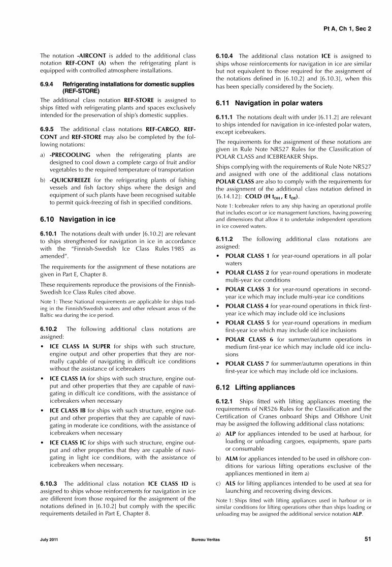
Pt A, Ch 1, Sec 2
The notation -AIRCONT is added to the additional classnotation REF-CONT (A) when the refrigerating plant isequipped with controlled atmosphere installations.
6.9.4 Refrigerating installations for domestic supplies (REF-STORE)
The additional class notation REF-STORE is assigned toships fitted with refrigerating plants and spaces exclusivelyintended for the preservation of ship’s domestic supplies.
6.9.5 The additional class notations REF-CARGO, REF-CONT and REF-STORE may also be completed by the fol-lowing notations:
a) -PRECOOLING when the refrigerating plants aredesigned to cool down a complete cargo of fruit and/orvegetables to the required temperature of transportation
b) -QUICKFREEZE for the refrigerating plants of fishingvessels and fish factory ships where the design andequipment of such plants have been recognised suitableto permit quick-freezing of fish in specified conditions.
6.10 Navigation in ice
6.10.1 The notations dealt with under [6.10.2] are relevantto ships strengthened for navigation in ice in accordancewith the “Finnish-Swedish Ice Class Rules 1985 asamended”.
The requirements for the assignment of these notations aregiven in Part E, Chapter 8.
These requirements reproduce the provisions of the Finnish-Swedish Ice Class Rules cited above.
Note 1: These National requirements are applicable for ships trad-ing in the Finnish/Swedish waters and other relevant areas of theBaltic sea during the ice period.
6.10.2 The following additional class notations areassigned:
• ICE CLASS IA SUPER for ships with such structure,engine output and other properties that they are nor-mally capable of navigating in difficult ice conditionswithout the assistance of icebreakers
• ICE CLASS IA for ships with such structure, engine out-put and other properties that they are capable of navi-gating in difficult ice conditions, with the assistance oficebreakers when necessary
• ICE CLASS IB for ships with such structure, engine out-put and other properties that they are capable of navi-gating in moderate ice conditions, with the assistance oficebreakers when necessary
• ICE CLASS IC for ships with such structure, engine out-put and other properties that they are capable of navi-gating in light ice conditions, with the assistance oficebreakers when necessary.
6.10.3 The additional class notation ICE CLASS ID isassigned to ships whose reinforcements for navigation in iceare different from those required for the assignment of thenotations defined in [6.10.2] but comply with the specificrequirements detailed in Part E, Chapter 8.
6.10.4 The additional class notation ICE is assigned toships whose reinforcements for navigation in ice are similarbut not equivalent to those required for the assignment ofthe notations defined in [6.10.2] and [6.10.3], when thishas been specially considered by the Society.
6.11 Navigation in polar waters
6.11.1 The notations dealt with under [6.11.2] are relevantto ships intended for navigation in ice-infested polar waters,except icebreakers.
The requirements for the assignment of these notations aregiven in Rule Note NR527 Rules for the Classification ofPOLAR CLASS and ICEBREAKER Ships.
Ships complying with the requirements of Rule Note NR527and assigned with one of the additional class notationsPOLAR CLASS are also to comply with the requirements forthe assignment of the additional class notation defined in[6.14.12]: COLD (H tDH , E tDE).
Note 1: Icebreaker refers to any ship having an operational profilethat includes escort or ice management functions, having poweringand dimensions that allow it to undertake independent operationsin ice covered waters.
6.11.2 The following additional class notations areassigned:
• POLAR CLASS 1 for year-round operations in all polarwaters
• POLAR CLASS 2 for year-round operations in moderatemulti-year ice conditions
• POLAR CLASS 3 for year-round operations in second-year ice which may include multi-year ice conditions
• POLAR CLASS 4 for year-round operations in thick first-year ice which may include old ice inclusions
• POLAR CLASS 5 for year-round operations in mediumfirst-year ice which may include old ice inclusions
• POLAR CLASS 6 for summer/autumn operations inmedium first-year ice which may include old ice inclu-sions
• POLAR CLASS 7 for summer/autumn operations in thinfirst-year ice which may include old ice inclusions.
6.12 Lifting appliances
6.12.1 Ships fitted with lifting appliances meeting therequirements of NR526 Rules for the Classification and theCertification of Cranes onboard Ships and Offshore Unitmay be assigned the following additional class notations:
a) ALP for appliances intended to be used at harbour, forloading or unloading cargoes, equipments, spare partsor consumable
b) ALM for appliances intended to be used in offshore con-ditions for various lifting operations exclusive of theappliances mentioned in item a)
c) ALS for lifting appliances intended to be used at sea forlaunching and recovering diving devices.
Note 1: Ships fitted with lifting appliances used in harbour or insimilar conditions for lifting operations other than ships loading orunloading may be assigned the additional service notation ALP.
July 2011 Bureau Veritas 51

Pt A, Ch 1, Sec 2
6.12.2 The additional class notations (ALP), (ALM), (ALS)may be assigned by the Society in lieu of the notations ALP,ALM, ALS respectively, when the corresponding liftingappliances meet the requirements of specific National Reg-ulations under the conditions defined in NR526.
6.12.3 The additional class notations ALP, ALM, ALS,(ALP), (ALM) or (ALS) are optional. However, the Societymay require the compliance of lifting appliances with theassigning conditions of one of the above mentioned addi-tional class notations for the classification of ships, whenone or several lifting appliances are of a primary impor-tance for their operation, or when such appliances signifi-cantly influence their structure. As a rule, such is the casefor the shear leg pontoons, crane pontoons, crane vessels,supporting ships for diving devices and when the liftingappliances concerned have special high capacities, forexample in case of ships specially equipped for handlingvery heavy loads.
6.12.4 In compliance with [6.1.3], these notations areassigned a construction mark as defined in [3].
Note 1: Rules for the Classification and Certification of LiftingAppliances of ships and offshore units (NR184) are applicable toderricks including heavy derricks and derricks in union purchase.
6.13 Emergency Response Service (ERS)
6.13.1 General
The notations dealt with under this Article are related to theprovision of technical assistance in case of a maritime acci-dent at sea by providing information on their remainingstrength and stability in the resulting damaged condition.
The requirements for the assignment and maintenance ofthese notations are given in NR556 (Emergency ResponseService).
6.13.2 ERS-S (Strength), ERS-H (Hydrodynamic) and ERS-M (Mooring) services
ERS-S corresponds to damage longitudinal strength anddamage stability analyses. It aims at providing informationon the remaining hull strength and stability after the acci-dent.
ERS-H aims at providing limits of navigation, based on Ver-tical Wave Bending Moment and Vertical Wave Shear Forcedirect calculations for the accidental site sea-states, insteadof empirical Rules formulae. It is only applied in comple-ment to ERS-S. It aims at providing maximum environmen-tal conditions (Hs), heading restriction, or speed limit.These limits of navigation are given for hull girder strengthonly.
ERS-M corresponds to damaged mooring analyses for per-manently moored units. It aims at providing information onthe remaining capacities of the mooring system after thefailure of one or several mooring lines and the potential fail-ure of an additional mooring line.
6.14 Other additional class notations
6.14.1 Strengthened bottom
The additional class notation STRENGTHBOTTOM may beassigned to ships built with specially strengthened bottomstructures so as to be able to be loaded and/or unloadedwhen properly stranded.
The requirements for the assignment of this notation aregiven in Pt E, Ch 10, Sec 1.
6.14.2 Loading by grabs
a) Loading by grabs for bulk carriers subject to NR522Common Structural Rules for Bulk Carriers
The additional class notation GRAB [X] is assigned toships with holds designed for loading/unloading bygrabs having a maximum specific weight up to [X] tons.
The requirements for the assignment of this notation aregiven in NR522 Common Structural Rules for Bulk Car-riers.
Note 1: It is reminded that for bulk carriers assigned with the addi-tional service feature CSR, and one of the additional servicefeatures BC-A or BC-B, GRAB [X] is assigned as a mandatoryadditional service feature.
For bulk carriers assigned with the additional service featureCSR others than above, GRAB [X] may be assigned on a volun-tary basis as an additional class notation.
It is to be noted that this additional class notation doesnot negate the use of heavier grabs, but the owner andoperators are to be made aware of the increased risk oflocal damage and possible early renewal of inner bot-tom plating if heavier grabs are used regularly or occa-sionally to discharge cargo.
b) Loading by grabs for ships other than those subject toNR522 Common Structural Rules for Bulk Carriers
The additional class notation GRABLOADING may beassigned to ships with hold tank tops specially rein-forced for loading/unloading cargoes by means of grabsor buckets.
The requirements for the assignment of this notation aregiven in Pt E, Ch 10, Sec 2.
Note 2: This additional class notation may only be assigned toships with the service notation general cargo ship (intended tocarry dry bulk cargoes), ore carrier, combination car-rier/OBO, combination carrier/OOC or bulk carrier notassigned with the additional service feature CSR.
However, this does not preclude ships not assigned withthis notation from being loaded/unloaded with grabs.
6.14.3 In-water survey
The additional class notation INWATERSURVEY may beassigned to ships provided with suitable arrangements tofacilitate the in-water surveys as provided in Ch 2, Sec 2,[5.4.5].
The requirements for the assignment of this notation aregiven in Pt E, Ch 10, Sec 3.
52 Bureau Veritas July 2011

Pt A, Ch 1, Sec 2
6.14.4 Single point mooring
The additional class notation SPM (Single Point Mooring)may be assigned to ships fitted with a specific mooringinstallation.
The requirements for the assignment of this notation aregiven in Pt E, Ch 10, Sec 4.
These requirements reproduce the provisions of “Recom-mendations for Equipment Employed in the Mooring ofShips at Single Point Mooring” (3rd edition 1993), issued byOCIMF (Oil Companies International Marine Forum).
6.14.5 Container lashing equipment
The additional class notation LASHING may be assigned toships initially fitted with mobile container lashing equip-ment which has been documented, tested and checked.
This notation is assigned only to ships having the servicenotation container ship or the additional service featureequipped for carriage of containers.
The requirements for the assignment of this notation aregiven in Pt E, Ch 10, Sec 5.
This equipment, however, will not be verified any longer atthe periodical class surveys to which the ship is submitted.
6.14.6 Dynamic positioning
The additional class notation DYNAPOS may be assigned toships equipped with a dynamic positioning system.
In compliance with [6.1.3], this notation is assigned a con-struction mark, as defined in [3].
The scope of the notation, including the additional keys forthe description of capability of the installation and therequirements for assignment, are given in Pt E, Ch 10, Sec 6.
6.14.7 Vapour control system
The additional class notation VCS (Vapour Control System)may be assigned to ships equipped with cargo vapour con-trol systems. The notation -TRANSFER is added to the nota-tion where, in addition, the ship is fitted with specificarrangements for transferring cargo vapours to another ship.
This notation is assigned only to ships having the servicenotation oil tanker, combination carrier/OBO ESP, combi-nation carrier/OOC ESP, liquefied gas carrier, chemicaltanker or FLS tanker.
The requirements for the assignment of this notation aregiven in Pt E, Ch 10, Sec 7.
6.14.8 Cofferdam ventilation
The additional class notation COVENT may be assigned toships having cofferdams in the cargo area which can beused as ballast tanks and which may be ventilated through afixed ventilation system.
This notation is assigned only to ships having the servicenotation bulk carrier, ore carrier, oil tanker, combinationcarrier/OBO, combination carrier/OOC, liquefied gas car-rier, chemical tanker or FLS tanker.
The requirements for the assignment of this notation aregiven in Pt E, Ch 10, Sec 8.
6.14.9 Centralised cargo controlThe additional class notation CARGOCONTROL may beassigned to ships (carrying liquid cargo in bulk) equippedwith a centralised system for handling cargo and ballast liq-uids.
In principle, this notation is assigned only to ships havingthe service notation oil tanker, combination carrier/OBO,combination carrier/OOC, chemical tanker or FLS tanker.
The requirements for the assignment of this notation aregiven in Pt E, Ch 10, Sec 9.
6.14.10 Ship manoeuvrabilityThe additional class notation MANOVR may be assigned toships complying with the requirements related to manoeu-vring capability defined in Pt E, Ch 10, Sec 10.Note 1: According to Resolution MSC.137(76), these provisions areto be applied to ships of all rudder and propulsion types, of 100 min length and over, and to chemical tankers and gas carriers regard-less of the length, which were constructed on or after 1 January2004.
6.14.11 Ship subdivision and damage stabilityThe additional class notation SDS may be assigned to shipsfor which a damage buoyancy, subdivision and stability filehas been examined and found to satisfy the requirementsgiven in Pt B, Ch 3, Sec 3.
An attestation of compliance may be issued to the InterestedParty, specifying the rules and criteria considered for theexamination of the file.Note 1: As a rule, class assigned to a ship does not cover require-ments applicable to the assignment of the notation SDS.
6.14.12 Ships operating in cold weather conditionsThe additional class notation COLD (H tDH , E tDE) may beassigned to ships intended to operate in cold weather con-ditions and fitted with arrangements for de-icing.
The requirements for the assignment of this notation aregiven in Pt E, Ch 10, Sec 11, where tDH and tDE are defined,respectively for hull and equipment, by:tDH : Design temperature, in °C, to be considered for
the hull, provided by the ship designertDE : Design temperature, in ° C, to be considered for
the equipment, provided by the ship designer.
6.14.13 Green passport for ship recyclingThe additional class notation GREEN PASSPORT may beassigned to ships for which requirements intended to facili-tate ship recycling have been applied, encompassing theidentification, quantification and localization of materialswhich may cause harm to the environment and peoplewhen the fittings or equipment containing such materialsare removed, or when the ship is recycled.
The requirements for the assignment and maintenance ofthis notation are given in NR528 Green passport.
6.14.14 Efficient washing of cargo tanksThe additional class notation EWCT may be assigned toships fitted with washing arrangements complying with therequirements given in Pt E, Ch 10, Sec 12.
This notation may only be assigned to ships having the serv-ice notation oil tanker, FLS tanker, or chemical tanker.
July 2011 Bureau Veritas 53

Pt A, Ch 1, Sec 2
6.14.15 Protected FO tank
The additional class notation PROTECTED FO TANK maybe assigned to ships with an aggregate oil fuel capacity ofless than 600 m3, fitted with oil fuel tanks complying withthe requirements given in Pt E, Ch 10, Sec 13.
6.14.16 Sealed liquefied natural gas carrier
The additional class notation IATP (increased admissiblecargo tank pressure) may only be assigned to ships havingthe service notation liquefied gas carrier and intended tocarry methane (LNG) whose maximum cargo tank designpressure does not exceed 70 kPa and that are designed andbuilt so as to allow the pressure in the tanks to increaseabove 25 kPa.
The requirements for the assignment of this notation aregiven in Pt E, Ch 10, Sec 14.
6.14.17 Enhanced fire protection for cargo ships and tankers (EFP-AMC)
The additional class notation EFP-A or EFP-M or EFP-C orEFP-AMC may be assigned to ships fitted with enhanced firesafety protection in, respectively, accommodation spaces ormachinery spaces or cargo areas or all these spaces andareas.
This notation is assigned only to ships having the servicenotations as per [4.2] (Cargo ships), or [4.3] (Bulk, ore andcombination carriers), or [4.4] (Ships carrying liquid cargoin bulk).
The requirements for the assignment of these notations aregiven in Pt E, Ch 10, Sec 15.
6.14.18 Design fatigue life for oil tankers subject to NR523 Common Structural Rules for Double Hull Oil tankers
The additional class notations:
• Fatigue PLUS
• Fatigue PLUS DFL xx
• Fatigue PLUS spectral ( ), and
• Fatigue PLUS spectral ( ) DFL xx,
may be assigned to ships for which the Society proposes anextended scope of critical details in addition to the detailsrequired to be checked by NR523 Common Structural Rulesfor Double Hull Oil Tankers.
The requirements for the assignment of these notations aregiven in NR552 Additional Class Notations Fatigue PLUSfor Oil Tanker CSR.
Note 1: The additional class notations Fatigue PLUS, Fatigue PLUSDFL xx, Fatigue PLUS spectral ( ) and Fatigue PLUS spectral ( )DFL xx may be assigned only to ships with the service notation oiltanker ESP CSR.
The additional class notation Fatigue PLUS is assigned if allanalysed details comply with a design fatigue life equal to25 years.
The additional class notation Fatigue PLUS DFL xx corre-sponds to the notation Fatigue PLUS with an extendeddesign fatigue life of xx years, with xx above 25.
The additional class notations Fatigue PLUS spectral ( ) andFatigue PLUS spectral ( ) DFL xx are introduced to considerwave environment areas encountered during trading otherthan that considered in NR523 Common Structural Rulesfor Double Hull Oil Tankers (i.e. North Atlantic). The infor-mation between brackets is a short description of the routeor areas encountered by the ship during its service life.
The additional class notation Fatigue PLUS spectral ( ) isassigned if all analysed details comply with a design fatiguelife equal to 25 years.
The additional class notation Fatigue PLUS spectral ( ) DFL xxis assigned if all analysed details comply with a design fatiguelife of xx years, with xx above 25.
6.14.19 Fast Oil Recovery System (FORS)
The additional class notation FORS may be assigned toships with oil fuel tanks and cargo tanks, as applicable, fit-ted with two (or more) connectors allowing the recovery ofthe tank contents as follows:
• by injecting sea water through one connector, the tankcontents being recovered through the other one, and
• by introducing a submersible pump in the tank throughone of the connectors.
The requirements for the assignment of this notation aregiven in NR553 Fast Oil Recovery System.
The additional class notation FORS may be completed bythe notation -NS when the connectors are intended to beused during the normal service of the ship and, for that pur-pose, comply with the additional requirements given inArticle [3] of NR553 Fast Oil Recovery System.
For ships not assigned with the notation -NS, the connectorsmay be used only to facilitate the recovery of the tank con-tents when the ship is damaged or wrecked.
6.14.20 High-Voltage Shore Connection Systems (HVSC)
The additional class notation HVSC may be assigned toships fitted with electrical and control engineering arrange-ments allowing operation of services by connection to anexternal high-voltage electrical power supply in port.
The requirements for the assignment of this notation aregiven in NR557 High-Voltage Shore Connection Systems.
6.14.21 SINGLEPASSLOADING
The additional class notation SINGLEPASSLOADING maybe assigned to ships having the service notation ore carrierwhich are specially designed for single pass loading.
Note 1: This additional class notation may be completed by thedesign loading rate, in tons per hour, for example:
SINGLEPASSLOADING [xxxxx t/h]
The additional class notation SINGLEPASSLOADING onlycovers the loading sequences provided to the Society, asreferred to in Pt E, Ch 10, Sec 16.
The requirements for the assignment of this notation aregiven in Pt E, Ch 10, Sec 16.
54 Bureau Veritas July 2011
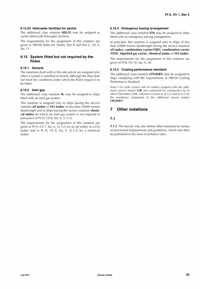
Pt A, Ch 1, Sec 2
6.14.22 Helicopter facilities for yachtsThe additional class notation HEL(Y) may be assigned toyachts fitted with helicopter facilities.
The requirements for the assignment of this notation aregiven in NR500 Rules for Yachts, Part B and Part C, Ch 4,Sec 11.
6.15 System fitted but not required by the Rules
6.15.1 GeneralThe notations dealt with in this sub-article are assigned onlywhen a system is installed on board, although the ship doesnot meet the conditions under which the Rules request it tobe fitted.
6.15.2 Inert gasThe additional class notation IG may be assigned to shipsfitted with an inert gas system.
This notation is assigned only to ships having the servicenotation oil tanker or FLS tanker of less than 20000 tonnesdeadweight and to ships having the service notation chemi-cal tanker for which an inert gas system is not required inpursuance of Pt D, Ch 8, Sec 9, [1.3.1].
The requirements for the assignment of this notation aregiven in Pt D, Ch 7, Sec 6, [5.1.2] for an oil tanker or a FLStanker and in Pt D, Ch 8, Sec 9, [2.5.3] for a chemicaltanker.
6.15.3 Emergency towing arrangementThe additional class notation ETA may be assigned to shipsfitted with an emergency towing arrangement.
In principle, this notation is assigned only to ships of lessthan 20000 tonnes deadweight having the service notationoil tanker, combination carrier/OBO, combination carrier/OOC, liquefied gas carrier, chemical tanker or FLS tanker.
The requirements for the assignment of this notation aregiven in Pt B, Ch 10, Sec 4, [4].
6.15.4 Coating performance standardThe additional class notation CPS(WBT) may be assigned toships complying with the requirements of NR530 CoatingPerformance Standard.
Note 1: For bulk carriers and oil tankers assigned with the addi-tional service feature CSR and contracted for construction on orafter 8 December 2006, reference is made to [4.3.2] and [4.4.2] forthe mandatory assignment of the additional service featureCPS(WBT).
7 Other notations
7.1
7.1.1 The Society may also define other notations by meansof provisional requirements and guidelines, which may thenbe published in the form of tentative rules.
July 2011 Bureau Veritas 55
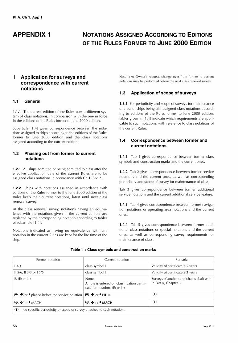
Pt A, Ch 1, App 1
APPENDIX 1 NOTATIONS ASSIGNED ACCORDING TO EDITIONS OF THE RULES FORMER TO JUNE 2000 EDITION
1 Application for surveys and correspondence with current notations
1.1 General
1.1.1 The current edition of the Rules uses a different sys-tem of class notations, in comparison with the one in forcein the editions of the Rules former to June 2000 edition.
Subarticle [1.4] gives correspondence between the nota-tions assigned to ships according to the editions of the Rulesformer to June 2000 edition and the class notationsassigned according to the current edition.
1.2 Phasing out from former to current notations
1.2.1 All ships admitted or being admitted to class after theeffective application date of the current Rules are to beassigned class notations in accordance with Ch 1, Sec 2.
1.2.2 Ships with notations assigned in accordance witheditions of the Rules former to the June 2000 edition of theRules keep their current notations, latest until next classrenewal survey.
At the class renewal survey, notations having an equiva-lence with the notations given in the current edition, arereplaced by the corresponding notation according to tablesof subarticle [1.4].
Notations indicated as having no equivalence with anynotation in the current Rules are kept for the life time of theship.
Note 1: At Owner’s request, change over from former to currentnotations may be performed before the next class renewal survey.
1.3 Application of scope of surveys
1.3.1 For periodicity and scope of surveys for maintenanceof class of ships being still assigned class notations accord-ing to editions of the Rules former to June 2000 edition,tables given in [1.4] indicate which requirements are appli-cable to such notations, with reference to class notations ofthe current Rules.
1.4 Correspondence between former and current notations
1.4.1 Tab 1 gives correspondence between former classsymbols and construction marks and the current ones.
1.4.2 Tab 2 gives correspondence between former servicenotations and the current ones, as well as correspondingperiodicity and scope of survey for maintenance of class.
Tab 3 gives correspondence between former additionalservice notations and the current additional service feature.
1.4.3 Tab 4 gives correspondence between former naviga-tion notations or operating area notations and the currentones.
1.4.4 Tab 5 gives correspondence between former addi-tional class notations or special notations and the currentones, as well as corresponding survey requirements formaintenance of class.
Table 1 : Class symbols and construction marks
Former notation Current notation Remarks
I 3/3 class symbol I Validity of certificate ≤ 5 years
II 5/6, II 3/3 or I 5/6 class symbol II Validity of certificate ≤ 3 years
E, (E) or (−) None.A note is entered on classification certifi-cate for notations (E) or (−)
Surveys of anchors and chains dealt with in Part A, Chapter 3
{, [ or µ placed before the service notation {, [ or µ HULL (1)
{, [ or µ MACH {, [ or µ MACH (1)
(1) No specific periodicity or scope of survey attached to such notation.
56 Bureau Veritas July 2011

Pt A, Ch 1, App 1
Table 2 : Service notations
Former notation Current notation Periodicity and scope of surveys
bulk carrier bulk carrier bulk carrier ESP or general cargo ship,as applicable
bulk carrier - oil tanker combination carrier/OBO combination carrier/OBO
cargoship general cargo ship general cargo ship
chemical tanker chemical tanker chemical tanker
containership container ship container ship
deck ship deck ship all ships
dredger dredger dredger
fire fighting ship 1, 2, 3, - or water spray fire fighting ship 1, 2, 3, E or water spraying fire fighting ship 1, 2, 3, E or water spraying
fishing vessel fishing vessel fishing vessel
floating dock floating dock floating dock
hopper barge hopper unit hopper unit
hopper dredger hopper dredger hopper dredger
HSC (CAT A or CAT B) HSC (-CAT A or -CAT B) HSC (CAT A or CAT B)
launch, seagoing launch launch, seagoing launch all ships
light ship light ship light ship
liquefied gas carrier liquefied gas carrier liquefied gas carrier
livestock carrier livestock carrier livestock carrier
oil recovery ship oil recovery ship oil recovery ship
oil tanker oil tanker oil tanker
ore carrier ore carrier ore carrier
ore carrier - oil tanker combination carrier/OOC combination carrier/OOC
passenger ferry ro-ro passenger ship ro-ro passenger ship
passenger ship passenger ship passenger ship
pontoon pontoon pontoon
pontoon/crane or pontoon/derrick pontoon - crane pontoon - crane
product tanker FLS tanker FLS tanker
pusher tug tug
refrigerated carrier refrigerated cargo ship refrigerated cargo ship
roll on - roll off ro-ro cargo ship ro-ro cargo ship
special service / ... special service - ... (1) special service - ... (1)
split hopper barge split hopper unit split hopper unit
split hopper dredger split hopper dredger split hopper dredger
supply vessel supply vessel supply vessel
tanker tanker tanker
tug tug tug
yacht yacht -motor-S or yacht -sailing-S (2) yacht
(1) Unless a new service notation corresponds to the specified service, such as cable laying ship.(2) Ships assigned with the service notation charter yacht according to the Rule Note NR381 keep their service notation latest until
next class renewal survey. At the next class renewal survey, or before it at Owner's request, the service notation is replaced bythe current service notation as per Rule Note NR500 (charter yacht-motor-S or charter yacht-sailing-S).
July 2011 Bureau Veritas 57
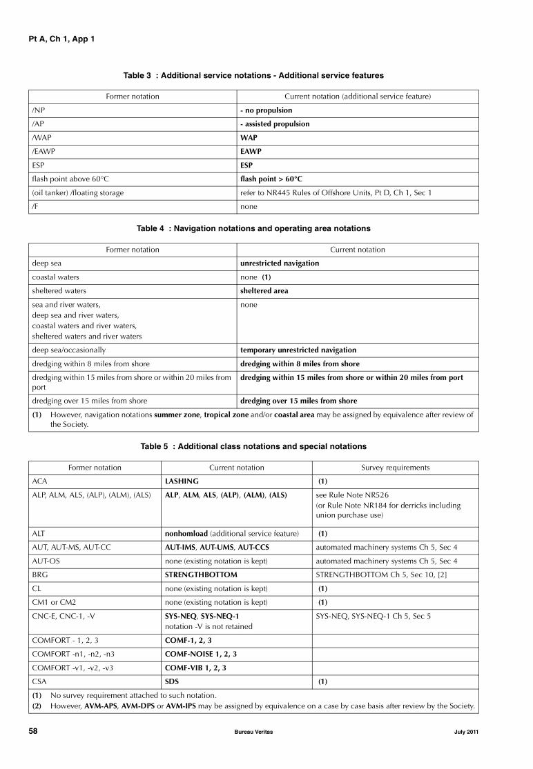
Pt A, Ch 1, App 1
Table 3 : Additional service notations - Additional service features
Table 4 : Navigation notations and operating area notations
Table 5 : Additional class notations and special notations
Former notation Current notation (additional service feature)
/NP - no propulsion
/AP - assisted propulsion
/WAP WAP
/EAWP EAWP
ESP ESP
flash point above 60°C flash point > 60°C
(oil tanker) /floating storage refer to NR445 Rules of Offshore Units, Pt D, Ch 1, Sec 1
/F none
Former notation Current notation
deep sea unrestricted navigation
coastal waters none (1)
sheltered waters sheltered area
sea and river waters,deep sea and river waters,coastal waters and river waters,sheltered waters and river waters
none
deep sea/occasionally temporary unrestricted navigation
dredging within 8 miles from shore dredging within 8 miles from shore
dredging within 15 miles from shore or within 20 miles from port
dredging within 15 miles from shore or within 20 miles from port
dredging over 15 miles from shore dredging over 15 miles from shore
(1) However, navigation notations summer zone, tropical zone and/or coastal area may be assigned by equivalence after review of the Society.
Former notation Current notation Survey requirements
ACA LASHING (1)
ALP, ALM, ALS, (ALP), (ALM), (ALS) ALP, ALM, ALS, (ALP), (ALM), (ALS) see Rule Note NR526 (or Rule Note NR184 for derricks including union purchase use)
ALT nonhomload (additional service feature) (1)
AUT, AUT-MS, AUT-CC AUT-IMS, AUT-UMS, AUT-CCS automated machinery systems Ch 5, Sec 4
AUT-OS none (existing notation is kept) automated machinery systems Ch 5, Sec 4
BRG STRENGTHBOTTOM STRENGTHBOTTOM Ch 5, Sec 10, [2]
CL none (existing notation is kept) (1)
CM1 or CM2 none (existing notation is kept) (1)
CNC-E, CNC-1, -V SYS-NEQ, SYS-NEQ-1notation -V is not retained
SYS-NEQ, SYS-NEQ-1 Ch 5, Sec 5
COMFORT - 1, 2, 3 COMF-1, 2, 3
COMFORT -n1, -n2, -n3 COMF-NOISE 1, 2, 3
COMFORT -v1, -v2, -v3 COMF-VIB 1, 2, 3
CSA SDS (1)
(1) No survey requirement attached to such notation.(2) However, AVM-APS, AVM-DPS or AVM-IPS may be assigned by equivalence on a case by case basis after review by the Society.
58 Bureau Veritas July 2011

Pt A, Ch 1, App 1
DEP none (existing notation is kept) (2) availability of machinery Ch 5, Sec 3
ETA ETAShips of 20000 tdw and above: existingnotation is kept only until next classrenewal survey and will be dropped after
see survey of emergency towing arrangement as per relevant service notation
F none (existing notation is kept) (1)
Heavy cargo heavy cargo (additional service feature) (1)
Heavy parcels on deck heavy cargo (additional service feature) (1)
Ice I super, Ice I, Ice II, Ice III none (existing notation is kept) arrangements for navigation in ice Ch 5, Sec 9
Ice Class IA Super, Ice Class IA,Ice Class IB, Ice Class IC
ICE CLASS IA SUPER, ICE CLASS IA,ICE CLASS IB, ICE CLASS IC
arrangements for navigation in ice Ch 5, Sec 9
Ice, Ice Class ID ICE, ICE CLASS ID arrangements for navigation in ice Ch 5, Sec 9
IG IGFor chemical tankers and oil tankers/FLStankers for which an inert gas system isrequired by the Rules, the existing notationis kept only until next class renewal surveyand will be dropped after
see survey of inert gas installation as per rele-vant service notation assigned
INT none (existing notation is kept) (1)
OIL POL-ENG, OIL POL-CARG,NLS-POL
none (existing notation is kept only untilnext class renewal survey and will bedropped after)
(1)
PDY DYNAPOS DYNAPOS Ch 5, Sec 10, [5]
PFA none (existing notation is kept only untilnext class renewal survey and will bedropped after)
see survey of internal platforms and ramps inCh 4, Sec 6
PORT AUT-PORT automated machinery systems Ch 5, Sec 4
PST, LCDT none (existing notation is kept) (1)
PTR none (existing notation is kept) survey of thruster installation (all ships)
(RMC) -A none (existing notation is kept) (1)
(RMC) /precooling, /quick freezing plant, /CA
-PRECOOLING, -QUICKFREEZE,-AIRCONT
refrigerating installations Ch 5, Sec 8
RMC, RMC-C, RMC-V REF-CARGO, REF-CONT, REF-STORE refrigerating installations Ch 5, Sec 8
RMC-S none (existing notation is kept) refrigerating installations Ch 5, Sec 8
SPM SPM SPM Ch 5, Sec 10, [4]
TOR, TOR-F none (existing notation is kept) (1)
Veristar notations hull and machinery VeriSTAR-HULL, VeriSTAR-HULL SIS, STAR-MACH, STAR-MACH SIS, STAR SIS
VeriSTAR system Ch 5, Sec 2
Former notation Current notation Survey requirements
(1) No survey requirement attached to such notation.(2) However, AVM-APS, AVM-DPS or AVM-IPS may be assigned by equivalence on a case by case basis after review by the Society.
July 2011 Bureau Veritas 59

Pt A, Ch 1, App 1
60 Bureau Veritas July 2011
Part AClassification and Surveys
Chapter 2
ASSIGNMENT, MAINTENANCE, SUSPENSION ANDWITHDRAWAL OF CLASS
SECTION 1 ASSIGNMENT OF CLASS
SECTION 2 MAINTENANCE OF CLASS
SECTION 3 SUSPENSION AND WITHDRAWAL OF CLASS
APPENDIX 1 PLANNED MAINTENANCE SURVEY SYSTEM
APPENDIX 2 CSM AND PMS SYSTEMS: SURVEYS CARRIED OUT BY THE CHIEF ENGINEER
APPENDIX 3 THICKNESS MEASUREMENTS: EXTENT, DETERMINATION OF LOCATIONS, ACCEPTANCE CRITERIA
July 2011 Bureau Veritas 61

62 Bureau Veritas July 2011
Pt A, Ch 2, Sec 1
SECTION 1 ASSIGNMENT OF CLASS
1 General
1.1
1.1.1 Class is assigned to a ship upon a survey, with theassociated operations, which is held in order to verifywhether it is eligible to be classed on the basis of the Rulesof the Society (see Ch 1, Sec 1, [1.3.2]). This may beachieved through:
• the completion of the new building, during which a sur-vey has been performed,
• a survey carried out according to the agreement devel-oped by the IACS Member Societies when ships changeclass between members, or
• a specific admission to class survey, in cases where aship is classed with a non-IACS Society or is not classedat all.
2 New building procedure
2.1 Ships surveyed by the Society during construction
2.1.1 When a ship is surveyed by the Society during con-struction, it is to comply with those requirements of theRules which are in force and applicable depending on theclass of the ship, taking into account the provisions of Ch 1,Sec 1, [2.1] and Ch 1, Sec 1, [2.2].
The hull surveys for new constructions are to be carried outin accordance with the requirements of Ch 3, Sec 7.
2.1.2 The Society:
• approves the plans and documentation submitted asrequired by the Rules
• proceeds, if required, with the appraisal of the design ofmaterials and equipment used in the construction of theship and their inspection at works
• carries out surveys, attends tests and trials provided forin the Rules, or obtains appropriate evidence to satisfyitself that the scantlings and construction meet the rulerequirements in relation to the approved drawings
• assigns the construction mark {; refer to Ch 1, Sec 2,[3.2.1].
2.1.3 The Society defines in specific Rules which materialsand equipment used for the construction of ships builtunder survey are, as a rule, subject to appraisal of theirdesign and to inspection at works, and according to whichparticulars.
2.1.4 As part of his interventions during the ship’s construc-tion and subject to the provisions of [2.1.2], the Surveyorwill:
• conduct an overall examination of the parts of the shipcovered by the Rules
• examine the construction methods and procedureswhen required by the Rules
• check selected items covered by the rule requirements
• attend tests and trials where applicable and deemednecessary.
2.1.5 Use of materials, machinery, appliances and items
As a general rule, all materials, machinery, boilers, auxiliaryinstallations, equipment, items etc. (generally referred to as"products") which are covered by the class and used or fit-ted on board ships surveyed by the Society during construc-tion are to be new and, where intended for essentialservices as defined in Ch 1, Sec 1, [1.2.1], tested by theSociety.
Second hand materials, machinery, appliances and itemsmay be used subject to the specific agreement of the Soci-ety and the Owner.
The requirements for the selection of materials to be used inthe construction of the various parts of a ship, the character-istics of products to be used for such parts and the checksrequired for their acceptance are to be as stated in Part C ofthe Rules and in NR 216 Materials, as applicable, or inother Parts of the Rules or as specified on approved plans. Inparticular, the testing of products manufactured accordingto quality assurance procedures approved by the Societyand the approval of such procedures are governed by therequirements of NR 216 Materials, Ch 1, Sec 1, [3].
2.1.6 Defects or deficiencies and their repair
The Society may, at any time, reject items found to bedefective or contrary to rule requirements or require supple-mentary inspections and tests and/or modifications, not-withstanding any previous certificates issued.
All repairs are subject to the preliminary agreement of theSociety. When the limits of tolerance for defects are speci-fied in the Rules concerned or by the Manufacturer, they areto be taken into account for repairs.
It is incumbent upon the Interested Party to notify the Soci-ety of any defects noted during the construction of the shipand/or of any item not complying with the applicablerequirements or in any case unsatisfactory. Proposalsregarding remedial actions intended to be adopted to elimi-nate such defects or unsatisfactory items are to be submittedto the Society and, if accepted, carried out to the Surveyor’ssatisfaction.
July 2011 Bureau Veritas 63
Pt A, Ch 2, Sec 1
2.1.7 Equivalence of Rule testing under certain conditions
Notwithstanding the provisions of [2.1.4], the Society may,at its discretion and subject to conditions and checksdeemed appropriate, accept certain materials, appliances ormachinery which have not been subjected to rule testing.
2.2 Other cases
2.2.1 When the procedure adopted does not comply withthat detailed in [2.1] but the Society deems that it is accept-able for the assignment of class, the construction mark µ isassigned in accordance with Ch 1, Sec 2, [3.2.3].
2.3 Documentation
2.3.1 Documentation relevant to the class applied for is tobe submitted for the approval of the Society.
2.3.2 The design data, calculations and plans to be submit-ted are listed in the relevant chapters of the Rules.The Society may also call for additional information accord-ing to the specific nature of the ship to be classed.
2.3.3 The documentation submitted to the Society is exam-ined in relation to the class applied for in the request forclassification. Note 1: Should the Interested Party subsequently wish to have theclass, in particular the service notation or navigation notation,granted to the ship modified, plans and drawings are generally tobe re-examined.
2.3.4 A copy of the submitted plans will be returned dulystamped, with remarks related to the compliance with therule requirements should the need arise.
2.3.5 As a rule, modifications of the approved plans regard-ing items covered by classification are to be submitted.
2.3.6 Design data to be submitted to the Society are toincorporate all information necessary for the assessment ofthe design of the ship for the purpose of assignment of class.It is the responsibility of the Interested Party to ascertain thatthe design data are correct, complete and compatible withthe use of the ship.
2.3.7 Design calculations are to be provided, when calledfor, as supporting documents to the submitted plans.
2.3.8 Design data and calculations are to be adequatelyreferenced. It is the duty of the Interested Party to ascertainthat the references used are correct, complete and applica-ble to the design of the ship.
2.3.9 The submitted plans are to contain all necessaryinformation for checking the compliance with the require-ments of the Rules.
2.3.10 In the case of conflicting information, submitteddocumentation will be considered in the following order ofprecedence: design data, plans, design calculations.
2.3.11 It is the responsibility of the Interested Party to ascer-tain that drawings used for the procurement, constructionand other works are in accordance with the approved plans.
3 Ships classed after construction
3.1 General
3.1.1 When an Owner applies to the Society for a shipalready in service to be admitted to class, the applicationwill be processed differently depending on whether the shipis:
• classed with an IACS Society, or
• not classed with an IACS Society.
3.2 Ships classed with an IACS Society
3.2.1 In this case, ships will be admitted to the Society’sclass upon satisfactory surveys and verification of documen-tation. For the extent and scope of the surveys to be carriedout and the list of documentation to be submitted by theInterested Party, reference is to be made to [3.2.2] and[3.2.3].
Note 1: For transfer of class at ship’s delivery, specific proceduresapply.
3.2.2 Surveys
Surveys to be carried out are based on the age of the shipand the updated current class status as provided by the pre-vious IACS Member Society. The extent of these surveys isto be at least the following.
a) Surveys of hull, ships without notation ESP:
• for ships of age less than 5 years, the survey is tohave the scope of an annual survey
• for ships which are 5 years of age and above but lessthan 10 years of age, in addition, the survey is toinclude the inspection of a representative number ofballast spaces
• for ships which are 10 years of age and above butless than 20 years of age, in addition, the survey is toinclude the inspection of a representative number ofcargo holds and/or cargo tanks, as applicable
• for ships which are 20 years of age and above, aclass renewal survey is to be carried out (thisrequirement is also applicable to ships having theirhull under continuous survey)
• in the latter case, if a bottom survey in dry conditionis not due at the time of transfer, consideration canbe given to carrying out a bottom in-water survey inlieu of bottom survey in dry condition.
b) Surveys of hull, ships with notation ESP:
• for ships of age less than 5 years, the survey is tohave the scope of an annual survey
• for ships between 5 and 10 years of age, in addition,the survey is to include the inspection of a represent-ative number of ballast spaces
• for ships which are 10 years of age and above butless than 15 years of age, in addition, the survey is toinclude the inspection of a representative number ofcargo holds and/or cargo tanks, as applicable
64 Bureau Veritas July 2011
Pt A, Ch 2, Sec 1
• for ships which are 15 years of age and above, butless than 20 years of age, the survey is to have thescope of a class renewal survey or of an intermedi-ate survey, whichever is due next
• for ships which are 20 years of age and above, thesurvey is to have the scope of a class renewal survey
• in the two latter cases, if a bottom survey in dry con-dition is not due at the time of transfer, considerationcan be given to carrying out a bottom in-water sur-vey in lieu of bottom survey in dry condition.
c) Survey of machinery. A general examination of allessential machinery is to be held including at least thefollowing:
• Examination under working condition of oil fuelburning equipment, boilers, economizers andsteam/steam generators. The adjustment of safetyvalves of this equipment is to be verified by check-ing the records on board ship
• All pressure vessels are to be examined
• Insulation resistance, generator circuit breakers,preference tripping relays and generator primemover governors are to be tested and paralleling andload sharing to be proved
• In all cases, navigating lights and indicators are to beexamined and their working and alternative sourcesof power verified
• Bilge pumps, emergency fire pumps and remotecontrols for oil valves, oil fuel pumps, lubricating oilpumps and forced draught fans are to be examinedunder working condition
• Recirculating and ice clearing arrangements, if any
• The main and all auxiliary machinery necessary foroperation of the ship at sea together with essentialcontrols and steering gear is to be tested underworking conditions. Alternative means of steeringare to be tested
• A short sea trial is to be held, at the Surveyor’s dis-cretion, if the ship has been laid up for a long period
• Initial start arrangements are to be verified
• In the case of oil tankers, the cargo oil system andelectrical installations in way of hazardous spacesare to be checked for compliance with rule require-ments. Where intrinsically safe equipment isinstalled, the Surveyors are to satisfy themselves thatsuch equipment has been approved by a recognisedauthority. The safety devices, alarms and essentialinstruments of the inert gas system are to be verifiedand the plant generally examined to ensure that itdoes not constitute a hazard to the ship.
3.2.3 DocumentationAs a rule, the documentation to be supplied is the follow-ing.
a) Main plans:
• General arrangement
• Capacity plan
• Hydrostatic curves
• Loading manual, where required.
b) Hull structure plans:
• Midship section
• Scantling plan
• Decks
• Shell expansion
• Transverse bulkheads
• Rudder and rudder stock
• Hatch covers.
c) Machinery plans:
• Machinery arrangement
• Intermediate, thrust and screw shafts
• Propeller
• Main engines, propulsion gears and clutch systems(or Manufacturer’s make, model and rating informa-tion)
• For steam turbine ships, main boilers, superheatersand economisers (or Manufacturer’s make, modeland rating information) and steam piping
• Bilge and ballast piping diagram
• Wiring diagram
• Steering gear system piping and arrangements andsteering gear Manufacturer’s make and model infor-mation
• Torsion vibration calculations, for ships less thantwo years old
• Plans for flexible couplings and/or torque limitingshafting devices in the propulsion line shafting (orManufacturer’s make, model and rating informa-tion), for ships assigned with one of the ice classadditional class notations described in Ch 1, Sec 2,[6.10.2]
• Pumping arrangements at the forward and afterends, drainage of cofferdams and pump rooms andgeneral arrangements of cargo piping in tanks andon decks, for oil tankers.
d) Plans required for ships assigned one of the additionalclass notations for Automated Machinery Systems:
• Instrument list
• Fire alarm system
• Plans for systematic maintenance and functioningtests.
Alternative technical data may be accepted by the Societyin lieu of specific items of the listed documentation notavailable at the time of the transfer of class.
3.2.4 For ships of less than 100 gross tonnage, special con-sideration will be given to the scope of surveys and docu-mentation to be supplied.
3.3 Ships not classed with an IACS Society
3.3.1 In this case, the class of the ship will be assignedupon a preliminary review of the documentation listed in[3.3.3] and subsequent satisfactory completion of the sur-veys, the extent and scope of which are given below.
July 2011 Bureau Veritas 65

Pt A, Ch 2, Sec 1
3.3.2 Surveys
The extent and scope of the admission to class survey are tobe not less than those required at the class renewal surveyof a ship of the same age and type; in addition all otherperiodical surveys should be performed together with thoseinspections which are linked to specific service notationsand/or additional class notations and/or special installationsthe ship is provided with.
3.3.3 Documentation
As a general rule, the documentation to be supplied to theSociety is not to be less than the following.
a) Main plans:
• General arrangement
• Capacity plan
• Loading cases, calculations of still water bendingmoments, and relevant documents, particulars ofloading calculator and instruction booklet as perSociety's requirements, according to the case
• Stability documents, if applicable (refer to Part B,Chapter 3).
b) Hull structure plans:
• Midship section
• Profile and deck plan
• Watertight bulkheads
• Rudder and rudder stock
• Shell expansion
• Hatch covers.
c) Machinery plans:
• Engine room general arrangement
• Diagram of fuel- (transfer, service), bilge-, ballast-,lubricating oil-, cooling-, steam- and feed-, generalservice and starting compressed air piping
• Diagram of fire-fighting systems
• Drawings of boilers and air receivers
• Drawings of shaft line, reduction gear and propeller
• Drawings of steering gear
• Torsion vibration calculations as per conditions laiddown in Pt C, Ch 1, Sec 9. Such documents arerequired only for ships less than 2 years old or forolder ships the propelling system of which has beenmodified during the two years preceding the classifi-cation.
d) Electrical installation plans:
• Master plan of power distribution, lighting andemergency power circuits
• Single line diagram of networks and switchboards
• Location and arrangement of electrical equipment inhazardous areas.
Alternative technical data may be accepted by the Societyin lieu of specific items of the listed documentation notavailable at the time of the transfer of class.
3.3.4 Where appropriate within reasonable limits, a provenservice record of satisfactory performance during a periodof adequate length may be used as a criterion of equiva-lence. Special consideration will be given to ships of recentconstruction.
3.3.5 For installations or equipment covered by additionalservice and/or class notations, the Society will determinethe documentation to be submitted.
3.3.6 In addition, the Society may base its judgement upondocumentation such as certificates issued or accepted bythe former Classification Society, if any, and statutory certifi-cates issued by the flag Administration or by a recognisedorganisation on its behalf; moreover, other documentsand/or plans may be specifically required to be supplied tothe Society in individual cases.
4 Date of initial classification
4.1 Definitions
4.1.1 Date of build
For a new building the date of build is the year and monthat which the new construction survey process is completed.Where there is a substantial delay between the completionof the construction survey process and the ship commenc-ing active service, the date of commissioning may be alsospecified.
If modifications are carried out, the date of build remainsassigned to the ship. Where a complete replacement oraddition of a major portion of the ship (e.g. forward section,after section, main cargo section) is involved, the followingapplies:
• the date of build associated with each major portion ofthe ship is indicated on the Classification Certificate
• survey requirements are based on the date of build asso-ciated with each major portion of the ship.
4.1.2 Date of initial classification for new buildings
As a general rule, for new buildings the date of initial classi-fication coincides with the date of build.
4.1.3 Date of initial classification for existing ships
In principle, for existing ships the date of initial classifica-tion is the date of completion of the admission to class sur-vey.
5 Reassignment of class
5.1
5.1.1 At the request of the Owner, a ship which was previ-ously classed with the Society, subsequently withdrawnfrom class and has not been classed since may have theclass reassigned subject to an admission to class survey. Ifapplicable and appropriate, account may be taken of anyperiodical surveys held in the former period of class withthe Society.
66 Bureau Veritas July 2011

Pt A, Ch 2, Sec 2
SECTION 2 MAINTENANCE OF CLASS
1 General principles of surveys
1.1 Survey types
1.1.1 Classed ships are submitted to surveys for the mainte-nance of class. These surveys include the class renewal sur-vey, intermediate and annual survey, bottom survey (eithersurvey in dry condition or in-water survey), tailshaft survey,boiler survey, and surveys for the maintenance of additionalclass notations, where applicable. Such surveys are carriedout at the intervals and under the conditions laid down inthis Section. In addition to the above periodical surveys,ships are to be submitted to occasional surveys wheneverthe circumstances so require; refer to [6], also when theowner requires a specific survey in case of sales; refer to [7]
1.1.2 The different types of periodical surveys are summa-rised in Tab 1. The intervals at which the periodical surveysare carried out are given in the items referred to in the sec-ond column of Tab 1. The relevant extent and scope aregiven in Part A, Chapter 3 and Part A, Chapter 4 for all shipsand for service notations, respectively, while surveys relatedto additional class notations are given in Part A, Chapter 5.Where there are no specific survey requirements for addi-tional class notations assigned to a ship, equipment and/orarrangements related to these additional class notations areto be examined, as applicable, to the Surveyor’s satisfactionat each class renewal survey for the class.
The surveys are to be carried out in accordance with the rel-evant requirements in order to confirm that the hull,machinery, equipment and appliances comply with the
applicable Rules and will remain in satisfactory conditionbased on the understanding and assumptions mentioned inCh 1, Sec 1, [3.3].
Where the conditions for the maintenance of the class, serv-ice notations and additional class notations are not com-plied with, the class and/or the service notation and/or theadditional class notations as appropriate will be suspendedand/or withdrawn in accordance with the applicable Rulesgiven in Ch 2, Sec 3.
Note 1: It is understood that requirements for surveys apply tothose items that are required according to the Rules or, even if notrequired, are fitted on board.
1.1.3 Unless specified otherwise, any survey other thanbottom survey and tailshaft survey may be effected by carry-ing out partial surveys at different times to be agreed uponwith the Society, provided that each partial survey is ade-quately extensive. The splitting of a survey into partial sur-veys is to be such as not to impair its effectiveness.
1.1.4 Special consideration may be given in application ofCh 3, Sec 1 to Ch 3, Sec 6 to commercial ships owned orchartered by Administrations, which are utilized in supportof military operations or service.
1.2 Change of periodicity, postponement or advance of surveys
1.2.1 The Society reserves the right, after due considera-tion, to change the periodicity, postpone or advance sur-veys, taking into account particular circumstances.
Table 1 : List of periodical surveys
Type of survey Reference in this Section Reference to scope of survey
Class renewal - hull [4] Ch 3, Sec 3 and Part A, Chapter 4 (1)
Class renewal - machinery [4] Ch 3, Sec 3 and Part A, Chapter 4 (1)
Class renewal - additional class notations [1.1] Part A, Chapter 5 (2)
Annual - hull [5.2] Ch 3, Sec 1 and Part A, Chapter 4 (1)
Annual - machinery [5.2] Ch 3, Sec 1 and Part A, Chapter 4 (1)
Annual - additional class notations [1.1] Part A, Chapter 5 (2)
Intermediate - hull [5.3] Ch 3, Sec 2 and Part A, Chapter 4 (1)
Intermediate - machinery [5.3] Ch 3, Sec 2 and Part A, Chapter 4 (1)
Bottom - dry condition [5.4] Ch 3, Sec 4
Bottom - in water [5.4] Ch 3, Sec 4
Tailshaft - complete [5.5] Ch 3, Sec 5
Tailshaft - modified [5.5] Ch 3, Sec 5
Boiler - complete [5.6] Ch 3, Sec 6
(1) As applicable, according to the service notation assigned to the ship.(2) As applicable, according to the additional class notations assigned to the ship.
July 2011 Bureau Veritas 67

Pt A, Ch 2, Sec 2
1.2.2 When a survey becomes overdue during a voyage,the following applies:
a) In the case of a class renewal survey, the Society maygrant an extension to allow for completion of the classrenewal survey, provided there is documented agree-ment to such an extension prior to the expiry date of theCertificate of Classification, adequate arrangementshave been made for attendance of the Surveyor at thefirst port of call and the Society is satisfied that there istechnical justification for such an extension. Such anextension will be granted only until arrival at the firstport of call after the expiry date of the Certificate ofClassification.
However, if owing to “exceptional circumstances” asdefined in [2.1.7], the class renewal survey cannot becompleted at the first port of call, the Society may grantan extension according to [4.1.1], but the total period ofextension shall in no case be longer than three monthsafter the original limit date of the class renewal survey.
b) In the case of annual and intermediate surveys, no post-ponement is granted. Such surveys are to be completedwithin their prescribed windows; see [2.1.3].
c) In the case of all other periodical surveys and recom-mendations, extension of class may be granted until thearrival of the ship at the port of destination.
1.3 Extension of scope of survey
1.3.1 The Society and/or its Surveyors may extend thescope of the provisions in Part A, Chapter 3 to Part A, Chap-ter 5, which set forth the technical requirements for surveys,whenever and so far as considered necessary, or modifythem in the case of special ships or systems.
1.3.2 The extent of any survey also depends upon the con-dition of the ship and its equipment. Should the Surveyorhave any doubt as to the maintenance or condition of theship or its equipment, or be advised of any deficiency ordamage which may affect the class, then further examina-tion and testing may be conducted as considered necessary.
1.4 General procedure of survey
1.4.1 The general procedure of survey consists in:
• an overall examination of the parts of the ship coveredby the rule requirements
• checking selected items covered by the rule require-ments
• attending tests and trials where applicable and deemednecessary by the Surveyor.
1.4.2 When a survey results in the identification of signifi-cant corrosion, structural defects or damage to hull,machinery and/or any piece of its equipment which, in theopinion of the Surveyor, affect the ship’s class, remedialmeasures are to be implemented before the ship continuesin service (see also [2.10]).
Note 1: The Society's survey requirements cannot be considered asa substitute for specification and acceptance of repairs and mainte-nance, which remain the responsibility of the Owner.
Note 2: In accordance with the provisions of Ch 1, Sec 1, [4.1.3],the Society will, at the request of the Owner, apply the regulationsof Administrations concerning the scope and periodicity of surveyswhen they differ from those laid down in [4] and [5].
Note 3: During the surveys, the Surveyor does not check that thespare parts are kept on board, maintained in working order andsuitably protected and lashed.
1.5 Appointment of another Surveyor
1.5.1 In compliance with the provisions of Ch 1, Sec 1,[2.4.1], should a disagreement arise between the Ownerand the Surveyor during a survey, the Society may, at therequest of the Owner, designate another Surveyor.
2 Definitions and procedures related to surveys
2.1 General
2.1.1 Period of class
Period of class means the period starting either from the dateof the initial classification, see Ch 2, Sec 1, [4], or from thecredited date of the last class renewal survey, and expiring atthe limit date assigned for the next class renewal survey.
2.1.2 Anniversary date
Anniversary date means the day of the month of each yearin the period of class which corresponds to the expiry dateof the period of class.
2.1.3 Survey time window
Survey time window, or more simply window, mean thefixed period during which annual and intermediate surveysare to be carried out.
2.1.4 Overdue surveys
Each periodical survey is assigned a limit date specified bythe relevant requirements of the Rules (end of survey inter-val or end date of window) by which it is to be completed.
A survey becomes overdue when it has not been completedby its limit date.
Examples:
• Anniversary date: 15th April
The 2000 annual survey can be validly carried out from16th January 2000 to 15th July 2000. If not completed by15th July 2000, the annual survey becomes overdue.
• Last bottom survey 20th October 2000:
If not completed by 20th October 2003 or end of theclass period, whichever comes first, the bottom surveybecomes overdue.
2.1.5 Recommendations
Any defect and/or deficiency affecting the class and to bedealt with within a specific period of time is indicated as arecommendation. A recommendation is pending until it iscleared. Where it is not cleared by its limit date, the recom-mendation is overdue.
68 Bureau Veritas July 2011
Pt A, Ch 2, Sec 2
2.1.6 MemorandaThose defects and/or deficiencies which do not affect themaintenance of class and which may therefore be cleared atthe Owner’s convenience and any other informationdeemed noteworthy for the Society’s convenience are indi-cated as memoranda. Memoranda are not to be regarded asrecommendations.
2.1.7 Exceptional circumstances“Exceptional circumstances” means:
• unavailability of dry-docking facilities, or
• unavailability of repair facilities, or
• unavailability of essential materials, equipment or spareparts, or
• delays incurred by action taken to avoid severe weatherconditions.
2.2 Terminology related to hull survey
2.2.1 Ballast tankA ballast tank is a tank that is being used primarily for saltwater ballast.
For single skin and double skin bulk carriers subject to therequirements of Ch 4, Sec 2, a ballast tank is a tank which isused solely for salt water ballast, or, where applicable, aspace which is used for both cargo and salt water ballastwill be treated as a ballast tank when substantial corrosionhas been found in that space, see [2.2.7]. For double skinbulk carriers, a double side tank is to be considered as aseparate tank even if it is in connection to either the topsidetank or the hopper side tank.
For oil tankers subject to the requirements of Ch 4, Sec 3and chemical tankers subject to the requirements of Ch 4,Sec 4, a ballast tank is a tank which is used solely for thecarriage of salt water ballast. A combined cargo/ballast tankis a tank which is used for the carriage of cargo or ballastwater as a routine part of the vessel’s operation and will betreated as a ballast tank. Cargo tanks in which water ballastmight be carried only in exceptional cases per MARPOLI/18(3) are to be treated as cargo tanks.
For liquefied gas carriers subject to the requirements of Ch4, Sec 5, a ballast tank is a tank which is used solely for thecarriage of salt water ballast.
2.2.2 SpacesSpaces are separate compartments including holds andtanks.
For ships subject to Ch 4, Sec 2, spaces are separate com-partments including holds, tanks, cofferdams and voidspaces bounding cargo holds, decks and the outer hull.
2.2.3 Overall surveyAn overall survey is a survey intended to report on the over-all condition of the hull structure and determine the extentof additional close-up surveys.
2.2.4 Close-up surveyA close-up survey is a survey where the details of structuralcomponents are within the close visual inspection range ofthe Surveyor, i.e. normally within reach of hand.
2.2.5 Transverse sectionA transverse section includes all longitudinal members con-tributing to longitudinal hull girder strength, such as plating,longitudinals and girders at the deck, sides, bottom, innerbottom, longitudinal bulkheads and, as applicable for thedifferent ship types, relevant longitudinals, hopper sides,bottom in top wing tanks, inner sides. For a transverselyframed ship, a transverse section includes adjacent framesand their end connections in way of transverse sections.
2.2.6 Representative tanks or spacesRepresentative tanks or spaces are those which areexpected to reflect the condition of other tanks or spaces ofsimilar type and service and with similar corrosion preven-tion systems. When selecting representative tanks or spaces,account is to be taken of the service and repair history onboard and identifiable critical structural areas and/or sus-pect areas.
2.2.7 Substantial corrosionSubstantial corrosion is an extent of corrosion such thatassessment of the corrosion pattern indicates a wastage inexcess of 75% of allowable margins, but within acceptablelimits.
For ships built under the Common Structural Rules for BulkCarriers (NR522) or the Common Structural Rules for Dou-ble Hull Oil Tankers (NR523), substantial corrosion is anextent of corrosion such that the assessment of the corro-sion pattern indicates a gauged (or measured) thicknessbetween (trenewal + 0,5 mm) and trenewal.Note 1: trenewal is the minimum allowable thickness, in mm, belowwhich renewal of structural members is to be carried out.
2.2.8 Suspect areasSuspect areas are locations showing substantial corrosionand/or considered by the Surveyor to be prone to rapidwastage.
2.2.9 Critical structural areasCritical structural areas are locations which have been iden-tified from calculations to require monitoring or from theservice history of the subject ship or from similar ships orsister ships (if available), to be sensitive to cracking, buck-ling or corrosion which would impair the structural integrityof the ship.
2.2.10 Corrosion prevention systemA corrosion prevention system is normally considered a fullhard protective coating.
Hard protective coating is usually to be epoxy coating orequivalent. Other coating systems, which are neither softnor semi-hard coatings, may be considered acceptable asalternatives, provided that they are applied and maintainedin compliance with the Manufacturer's specifications.
2.2.11 Coating conditionCoating condition is defined as follows:• good: condition with only minor spot rusting• fair: condition with local breakdown at edges of stiffen-
ers and weld connections and/or light rusting over 20%or more of areas under consideration, but less than asdefined for poor condition
July 2011 Bureau Veritas 69
Pt A, Ch 2, Sec 2
• poor: condition with general breakdown of coating over20% or more or hard scale at 10% or more, of areasunder consideration.
2.2.12 Cargo area (ships carrying liquid cargo in bulk)The cargo area is that part of the ship which contains cargotanks, slop tanks and cargo/ballast pump rooms, compres-sor rooms, cofferdams, ballast tanks and void spaces adja-cent to cargo tanks and also deck areas throughout theentire length and breadth of the part of the ship over theabove-mentioned spaces.
2.2.13 Cargo length area (dry cargo ships)The cargo length area is that part of the ship which includescargo holds and adjacent areas including fuel tanks, coffer-dams, ballast tanks and void spaces.
2.2.14 Prompt and thorough repairA “Prompt and thorough repair” is a permanent repair com-pleted at the time of survey to the satisfaction of the Sur-veyor, therein removing the need for the imposition of anyassociated recommendation. See also [2.10].
2.2.15 Special considerationSpecial consideration or specially considered (in connec-tion with close-up surveys and thickness measurements)means sufficient close-up inspection and thickness meas-urements are to be taken to confirm the actual average con-dition of the structure under the coating.
2.2.16 Air pipe headAir pipe heads installed on the exposed decks are thoseextending above the freeboard deck or superstructure decks.
2.3 Procedures for thickness measurements
2.3.1 When required as per the scope of surveys definedbelow, thickness measurements are normally to be carriedout under the responsibility of the Owner, and in the pres-ence of the Surveyor, by a service supplier independentfrom the Owner.
2.3.2 For all ships, the following applies:• thickness measurements required in the context of sur-
veys of hull structure is to be witnessed by a Surveyor.This requires the Surveyor to be on board while thegaugings are taken, enabling him at any time to inter-vene and to control the process.
• prior to commencement of the intermediate or classrenewal survey, a meeting is to be held between theattending Surveyor(s), the master of the ship or anappropriately qualified representative appointed by themaster or Company, the Owner’s representative(s) inattendance and the thickness measurement firm’s repre-sentative(s) so as to ensure the safe and efficient execu-tion of the surveys and thickness measurements to becarried out onboard.
2.3.3 In any kind of survey, i.e. class renewal, intermediate,annual or other surveys having the same scope, thicknessmeasurements of structures in areas where close-up surveysare required, are to be carried out simultaneously withclose-up surveys.
2.3.4 Thickness measurement is normally to be carried outby means of ultrasonic test equipment. The accuracy of theequipment is to be proven to the Surveyor as required. Thethickness measurements are to be carried out by a companyauthorised by the Society.
The Society reserves the right to limit the scope of authorisa-tion of the Company.
Note 1: Rule Note NR533 Approval of Service Suppliers givesdetails about the authorisation.
2.3.5 A thickness measurement report is to be prepared.The report is to give the location of measurements, thethickness measured and the corresponding original thick-ness. Furthermore, the report is to include the date whenthe measurements were carried out, the type of measuringequipment, the names and the qualification of the operatorsand their signatures.
The Surveyor is to review the final thickness measurementreport and countersign the cover page.
2.3.6 For acceptance criteria applicable to structural corro-sion diminution levels, reference is to be made to Ch 2, App3.
2.4 Agreement of firms for in-water survey
2.4.1 The in-water surveys referred to in the Rules are to becarried out by a certified company accepted by the Society.
Note 1: Rule Note NR533 Approval of Service Suppliers givesdetails about the certification.
2.5 Preparations and conditions for surveys
2.5.1 The Owner is to provide the necessary facilities for thesafe execution of the surveys, as per Ch 1, Sec 1, [3.2.2].
2.5.2 Cargo holds, tanks and spaces are to be safe foraccess. Cargo holds, tanks and spaces are to be gas free andproperly ventilated. Prior to entering a tank, void orenclosed space, it is to be verified that the atmosphere inthe tank or space is free from hazardous gas and containssufficient oxygen.
In preparation for survey and thickness measurements andto allow for a thorough examination, all spaces are to becleaned including removal from surfaces of all loose accu-mulated corrosion scale. Spaces are to be sufficiently cleanand free from water, scale, dirt, oil residues, etc. to revealcorrosion, deformation, fractures, damages or other struc-tural deterioration as well as the condition of the coating.However, those areas of structure whose renewal hasalready been decided by the Owner need only be cleanedand descaled to the extent necessary to determine the limitsof the areas to be renewed.
Sufficient illumination is to be provided to reveal corrosion,deformation, fractures, damages or other structural deterio-ration as well as condition of the coating.
70 Bureau Veritas July 2011
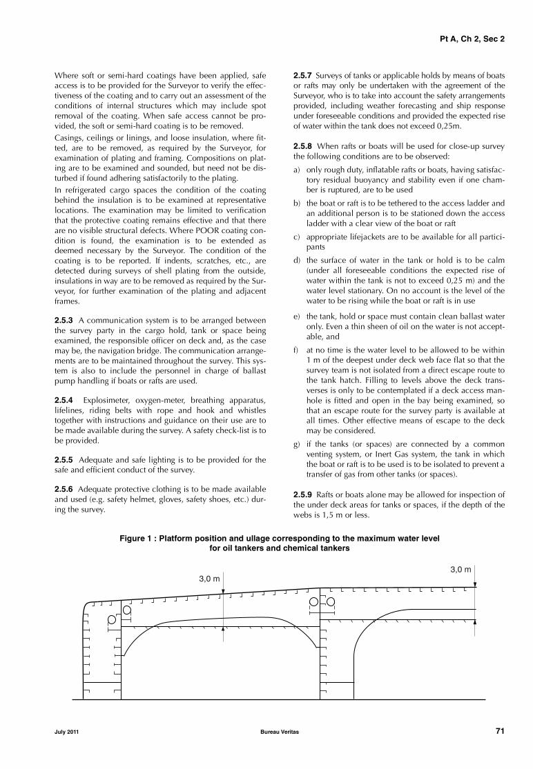
Pt A, Ch 2, Sec 2
Where soft or semi-hard coatings have been applied, safeaccess is to be provided for the Surveyor to verify the effec-tiveness of the coating and to carry out an assessment of theconditions of internal structures which may include spotremoval of the coating. When safe access cannot be pro-vided, the soft or semi-hard coating is to be removed.Casings, ceilings or linings, and loose insulation, where fit-ted, are to be removed, as required by the Surveyor, forexamination of plating and framing. Compositions on plat-ing are to be examined and sounded, but need not be dis-turbed if found adhering satisfactorily to the plating.In refrigerated cargo spaces the condition of the coatingbehind the insulation is to be examined at representativelocations. The examination may be limited to verificationthat the protective coating remains effective and that thereare no visible structural defects. Where POOR coating con-dition is found, the examination is to be extended asdeemed necessary by the Surveyor. The condition of thecoating is to be reported. If indents, scratches, etc., aredetected during surveys of shell plating from the outside,insulations in way are to be removed as required by the Sur-veyor, for further examination of the plating and adjacentframes.
2.5.3 A communication system is to be arranged betweenthe survey party in the cargo hold, tank or space beingexamined, the responsible officer on deck and, as the casemay be, the navigation bridge. The communication arrange-ments are to be maintained throughout the survey. This sys-tem is also to include the personnel in charge of ballastpump handling if boats or rafts are used.
2.5.4 Explosimeter, oxygen-meter, breathing apparatus,lifelines, riding belts with rope and hook and whistlestogether with instructions and guidance on their use are tobe made available during the survey. A safety check-list is tobe provided.
2.5.5 Adequate and safe lighting is to be provided for thesafe and efficient conduct of the survey.
2.5.6 Adequate protective clothing is to be made availableand used (e.g. safety helmet, gloves, safety shoes, etc.) dur-ing the survey.
2.5.7 Surveys of tanks or applicable holds by means of boatsor rafts may only be undertaken with the agreement of theSurveyor, who is to take into account the safety arrangementsprovided, including weather forecasting and ship responseunder foreseeable conditions and provided the expected riseof water within the tank does not exceed 0,25m.
2.5.8 When rafts or boats will be used for close-up surveythe following conditions are to be observed:
a) only rough duty, inflatable rafts or boats, having satisfac-tory residual buoyancy and stability even if one cham-ber is ruptured, are to be used
b) the boat or raft is to be tethered to the access ladder andan additional person is to be stationed down the accessladder with a clear view of the boat or raft
c) appropriate lifejackets are to be available for all partici-pants
d) the surface of water in the tank or hold is to be calm(under all foreseeable conditions the expected rise ofwater within the tank is not to exceed 0,25 m) and thewater level stationary. On no account is the level of thewater to be rising while the boat or raft is in use
e) the tank, hold or space must contain clean ballast wateronly. Even a thin sheen of oil on the water is not accept-able, and
f) at no time is the water level to be allowed to be within1 m of the deepest under deck web face flat so that thesurvey team is not isolated from a direct escape route tothe tank hatch. Filling to levels above the deck trans-verses is only to be contemplated if a deck access man-hole is fitted and open in the bay being examined, sothat an escape route for the survey party is available atall times. Other effective means of escape to the deckmay be considered.
g) if the tanks (or spaces) are connected by a commonventing system, or Inert Gas system, the tank in whichthe boat or raft is to be used is to be isolated to prevent atransfer of gas from other tanks (or spaces).
2.5.9 Rafts or boats alone may be allowed for inspection ofthe under deck areas for tanks or spaces, if the depth of thewebs is 1,5 m or less.
Figure 1 : Platform position and ullage corresponding to the maximum water levelfor oil tankers and chemical tankers
��� �
��� �
July 2011 Bureau Veritas 71

Pt A, Ch 2, Sec 2
If the depth of the webs is more than 1,5 m, rafts or boatsalone may be allowed only:
• when the coating of the under deck structure is inGOOD condition and there is no evidence of wastage;or
• if a permanent means of access is provided in each bayto allow safe entry and exit. This means:
- access direct from the deck via a vertical ladder anda small platform fitted approximately 2 m below thedeck in each bay; or
- access to deck from a longitudinal permanent plat-form having ladders to deck in each end of the tank.The platform shall, for the full length of the tank, bearranged in level with, or above, the maximumwater level needed for rafting of under deck struc-ture. For this purpose, the ullage corresponding tothe maximum water level is to be assumed not morethan 3 m from the deck plate measured at the mid-span of deck transverses and in the middle length ofthe tank (see Fig 1).
If neither of the above conditions are met, then staging or another equivalent means is to be provided for the survey ofthe under deck areas.
The use of rafts or boats as mentioned above does not pre-clude the use of boats or rafts to move about within a tankduring a survey.
2.5.10 When examination of associated structure isrequired, the following applies:
• ceilings in holds and floors in the engine room are to belifted to the necessary extent for examination of thestructure
• cement or other protective sheathing is to be removedwhen there is any doubt as to the condition of the plat-ing underneath or when adherence to plating is not tight
• in the case of solid ballast spaces, the solid ballast is tobe partially removed for examination of the condition ofthe structure in way. Should doubts arise, the Surveyormay require more extensive removal of the solid ballast
• insulation of compartments intended for refrigeratedcargoes is to be removed over the necessary extent forexamination by the Surveyor of the condition of thestructure, unless constructional arrangements makesuch inspections possible without removing the insula-tion.
2.6 Access to structures
2.6.1 For overall survey, means are to be provided to ena-ble the Surveyor to examine the hull structure in a safe andpractical way.
2.6.2 For close-up survey, one or more of the followingmeans for access, acceptable to the Surveyor, is to be pro-vided:
• permanent staging and passages through structures
• temporary staging and passages through structures
• lifts and movable platforms
• boats or rafts
• other equivalent means.
2.7 Equipment for surveys
2.7.1 One or more of the following fracture detection pro-cedures may be required if deemed necessary by the Sur-veyor:
• radiographic equipment
• ultrasonic equipment
• magnetic particle equipment
• dye penetrant.
2.8 Surveys at sea and anchorage
2.8.1 Surveys at sea or at anchorage may be accepted pro-vided the Surveyor is given the necessary assistance by thepersonnel on board. Precautions and procedures for carry-ing out the survey are to be in accordance with [2.5], [2.6]and [2.7].
2.9 Repairs and maintenance during voyage
2.9.1 Where repairs to hull, machinery or other equipment,which affect or may affect the class, are to be carried out bya riding crew during a voyage, they are to be planned inadvance. A complete repair procedure including the extentof proposed repair and the need for the Surveyor's attend-ance during the voyage is to be submitted to the Society forapproval sufficiently in advance. Failure to notify the Soci-ety in advance of the repairs may result in the suspension ofclass of the ship.
Where in any emergency circumstance, emergency repairsare to be effected immediately, the repairs should be docu-mented in the ship’s log and submitted thereafter to theSociety for use in determining further survey requirements.
2.9.2 The above is not intended to include maintenance toand overhaul of the hull, machinery and equipment inaccordance with the Manufacturer’s recommended proce-dures and established marine practice, which does notrequire the Society's agreement. However, any repair result-ing from such maintenance and overhauls which affects ormay affect the class is to be noted in the ship's log and sub-mitted to the attending Surveyor for use in determining fur-ther survey requirements.
2.10 Repairs
2.10.1 Any damage in association with wastage over theallowable limits (including buckling, grooving, detachmentor fracture), or extensive areas of wastage over the allowa-ble limits, which affects or, in the opinion of the Surveyor,will affect the ship’s structural, watertight or weathertightintegrity, is to be promptly and thoroughly (see [2.2.14])repaired.
72 Bureau Veritas July 2011

Pt A, Ch 2, Sec 2
Areas to be considered include, as applicable for the differ-ent ship types:
• side structure and side plating; side shell frames, theirend attachments and adjacent shell plating; inner sidestructure and inner side plating
• deck structure and deck plating
• bottom structure and bottom plating; inner bottomstructure and inner bottom plating
• longitudinal bulkheads structure and longitudinal bulk-heads plating, where fitted
• watertight or oiltight bulkheads structure and plating
• hatch covers or hatch coamings, where fitted
• weld connection between air pipes and deck plating
• air pipe heads installed on the exposed decks
• ventilators, including closing devices, if any; bunkerand vent piping systems.
2.10.2 For locations where adequate repair facilities arenot available, consideration may be given to allow the shipto proceed directly to a repair facility. This may require dis-charging the cargo and/or temporary repairs for theintended voyage.
2.10.3 Additionally, when a survey results in the identifica-tion of structural defects or corrosion, either of which, in theopinion of the Surveyor, will impair the vessel’s fitness forcontinued service, remedial measures are to be imple-mented before the ship continues in service.
3 Certificate of Classification: issue, validity, endorsement and renewal
3.1 Issue of Certificate of Classification
3.1.1 A Certificate of Classification, bearing the class nota-tions assigned to the ship and an expiry date, is issued toany classed ship. This certificate is also provided withannexes supplying information necessary for the manage-ment of the certificate and for carrying out the class surveys.
3.1.2 A Provisional Certificate of Classification may serveas a Certificate of Classification in some cases, such as afteran admission to class survey, after a class renewal survey, orwhen the Society deems it necessary.
3.1.3 The Certificate of Classification and relevant annexesare to be made available to the Society’s Surveyors uponrequest.
3.2 Validity of Certificate of Classification, maintenance of class
3.2.1 According to Ch 1, Sec 1, [2.4], the Society alone isqualified to confirm the class of the ship and the validity ofits Certificate of Classification.
3.2.2 During the class period, a Certificate of Classificationis valid when it is not expired.
The class is maintained during a certain period or at a givendate, when during the said period or at such date the condi-tions for suspension or withdrawal of class are not met.
Refer also to Ch 1, Sec 1, [1.3.4].
3.2.3 At the request of the Owner, a statement confirmingthe maintenance of class may be issued by the Societybased on the information in its records for that ship at thetime.
This statement is issued on the assumption that the Ownerhas complied with the Rules, in particular with [6].
Should any information which would have prevented theSociety from issuing the statement and which was not avail-able at the time subsequently come to light, the statementmay be cancelled.
Attention is drawn to Ch 2, Sec 3, [1.2], whereby the Soci-ety, upon becoming aware of a breach of the Rules, isempowered to suspend class from the date of the breach,which may be prior to the date of the statement.
3.2.4 According to the same conditions as in [3.2.3], astatement declaring that the class is maintained “clean andfree from recommendation’’ may be issued by the Societywhen there is no pending recommendation at that date.
3.2.5 Classification-related documents and information areliable to be invalidated by the Society whenever their objectis found to differ from that on which they were based or tobe contrary to the applicable requirements. The Owner isliable for any damage which may be caused to any thirdparty from improper use of such documents and informa-tion.
3.3 Endorsement of Certificate of Classification
3.3.1 Text of endorsement
When surveys are satisfactorily carried out, the Certificateof Classification is generally endorsed accordingly, with therelevant entries in the appropriate annexes.
Each endorsement normally consists of sections for thedescription of:
• the surveys held
• the imposed, deleted and postponed recommendations(including the assigned limit date as applicable)
• the unchanged existing recommendations (given forinformation only).
Where applicable, memoranda are also endorsed in theappropriate annex.
3.3.2 Possible modifications to endorsements
The Society reserves the right to modify the endorsementsmade by Surveyors.
July 2011 Bureau Veritas 73
Pt A, Ch 2, Sec 2
3.4 Status of surveys and recommendations
3.4.1 Information given in the Certificate of Classification,associated endorsements, Rules and specific documentsenables the Owner to identify the status of surveys and rec-ommendations.
3.4.2 The omission of such information does not absolvethe Owner from ensuring that surveys are held by the limitdates and pending recommendations are cleared to avoidany inconvenience which is liable to result from the suspen-sion or withdrawal of class; see Ch 2, Sec 3.
4 Class renewal survey
4.1 General principles
4.1.1 Class renewal surveys are to be carried out at five-year (class symbol I) or three-year (class symbol II) intervals.However, consideration may be given by the Society togranting an extension for a maximum of three months afterthe limit date, in exceptional circumstances. In such casesthe next period of class will start from the limit date for theprevious class renewal survey before the extension wasgranted.
4.1.2 For surveys completed within three months beforethe limit date of the class renewal survey, the next period ofclass will start from this limit date. For surveys completedmore than three months before the limit date, the period ofclass will start from the survey completion date.
4.1.3 A new period of class is assigned to the ship after thesatisfactory completion of the class renewal survey, and anew Certificate of Classification with relevant annexes isissued for the new period of class.
4.1.4 Concurrent crediting to both Intermediate Survey andClass Renewal Survey for surveys and thickness measure-ments of spaces are not acceptable.
4.2 Normal survey system (SS)
4.2.1 When the normal survey system is applied to shipswith a 5 years period of class, the class renewal survey maybe commenced at the fourth annual survey and continuedduring the following year with a view to completion by itsdue date. In this case the survey may be carried out by par-tial surveys at different times. The number of checks to beperformed at each partial survey and the interval betweenpartial surveys are to be agreed by the Society.
4.2.2 A class renewal survey may be commenced beforethe fourth annual survey at the request of the Owner. In thiscase, the survey is to be completed within fifteen months.The conditions for the execution of partial surveys are thesame as those referred to in [4.2.1].
4.3 Continuous survey system (CS)
4.3.1 The request by the Owner for admission to the con-tinuous survey system will be considered by the Society andagreement depends on the type and age of hull andmachinery. This system may apply to the class renewal sur-vey of hull (CSH), machinery (CSM) or other installationssuch as refrigerating installations (CSR) covered by an addi-tional class notation.
4.3.2 The continuous survey system is not applicable to theclass renewal survey of the hull of those ships subject to theEnhanced Survey Program (ESP), i.e. ships with the servicenotation oil tanker, combination carrier, bulk carrier, orecarrier or chemical tanker, nor to ships subject to therequirements of Ch 4, Sec 7, nor to ships with the class sym-bol II.
For ships subject to the requirements of Ch 4, Sec 7, thechangeover from the continuous survey system to the normalsurvey system is to be carried out not later than the due dateof the next intermediate survey or the due date of the end ofthe class period, whichever comes first after 1 July 2005.
In this connection:
• all items credited for continuous survey within the 15months prior to the date of changeover may be acceptedwithout further survey unless considered necessary bythe Surveyor
• all other items are to be surveyed and credited at thedate of changeover.
4.3.3 For ships other than those referred to in [4.3.2], thecontinuous survey system is not applicable to the classrenewal survey of the hull of ships over 20 years old. How-ever, consideration may be given, at the discretion of theSociety, to the applicability of the continuous survey systemto the class renewal survey of the hull of ships over 20 yearsold.
4.3.4 When the continuous survey system is applied, this isindicated in the Certificate of Classification and appropriatenotations as indicated in [4.3.1] are entered in the Registerof Ships.
4.3.5 Ships subject to the continuous survey system areprovided with lists of items to be surveyed under this sys-tem; these lists are attached to the Certificate of Classifica-tion.
4.3.6 For items surveyed under the continuous survey sys-tem, the following requirements generally apply:
a) the interval between two consecutive surveys of eachitem is not to exceed five years
b) the items are to be surveyed in rotation, so far as practi-cable ensuring that approximately equivalent portionsare examined each year
c) the Society may credit for continuous survey results ofsurveys carried out before the admission to the continu-ous survey scheme
d) each item is to be surveyed at one time, as far as practi-cable; the Society may, however, allow possible repairwork to be carried out within a certain period.
74 Bureau Veritas July 2011
Pt A, Ch 2, Sec 2
4.3.7 For ships more than ten years of age, the ballast tanksare to be internally examined twice in each five-year classperiod, i.e. once within the scope of the intermediate sur-vey and once within the scope of the continuous survey sys-tem for the class renewal survey.
4.3.8 For ships under continuous survey, items notincluded in the continuous survey cycle are to be inspectedaccording to the provisions given in [4.2]. Bottom surveysare to be carried out according to the requirements of [5.4].In addition, the bottom survey which is to be carried out inconjunction with the end of class period is to be performedwithin 15 months before the end of this class period.
4.3.9 Upon application by the Owner, the Society mayagree, subject to certain conditions, that some items ofmachinery which are included in the continuous surveycycle are examined by the Chief Engineer where the Societyis not represented. The Chief Engineer’s inspection is to befollowed by a confirmatory survey carried out by a Sur-veyor. The conditions for the application of this procedureare given in Ch 2, App 2.
4.3.10 The continuous survey system does not supersedethe annual surveys and other periodical and occasional sur-veys.
4.3.11 A general examination of the ship, as detailed in Ch3, Sec 1 for annual surveys, is to be carried out at the end ofthe period of class.
4.3.12 For laid-up ships, specific requirements given in[8.1] apply.
4.3.13 The continuous survey system may be discontinuedat any time at the discretion of the Society, or at the requestof the Owner, and a specific arrangement devised.
4.4 Planned maintenance survey system for machinery (PMS)
4.4.1 A planned maintenance survey system may be con-sidered as an alternative to the continuous survey system formachinery and is limited to components and systems cov-ered by it. When such a system approved by the Society isimplemented, a survey system other than those normallyadopted and with intervals different from those of the con-tinuous survey system as detailed in [4.3] may be accepted.
4.4.2 The conditions for approval of the planned mainte-nance survey system, the determination of survey itemintervals and the general scope of surveys are detailed in Ch2, App 1.
4.4.3 When the planned maintenance survey system isapplied, this is indicated in the Certificate of Classificationand notation PMS is entered in the Register of Ships.
4.4.4 The conditions related to Chief Engineer’s inspectionswithin the scope of PMS are given in Ch 2, App 2.
4.4.5 The planned maintenance survey system does notsupersede the annual surveys and other periodical andoccasional surveys.
4.4.6 A general examination of the machinery, as detailedin Ch 3, Sec 1 for annual surveys, is to be carried out at theend of the period of class.
4.4.7 The planned maintenance survey system may be dis-continued at any time at the discretion of the Society, or atthe request of the Owner, and a specific arrangementdevised.
5 Other periodical surveys
5.1 General
5.1.1 The different types of periodical surveys are summa-rised in Tab 1.
5.2 Annual surveys
5.2.1 Annual surveys are to be carried out within threemonths before or after each anniversary date.
5.3 Intermediate surveys
5.3.1 An intermediate survey, where applicable, is to becarried out within the window from three months before thesecond to three months after the third anniversary date.
5.3.2 The intermediate survey is applicable at any period ofclass to ships with the service notations oil tanker, chemicaltanker, FLS tanker, liquefied gas carrier, combination car-rier/OBO, combination carrier/OOC or to ships with theservice notation yacht of less than 24 meters in length.
5.3.3 The intermediate survey is applicable at any period ofclass to ships other than those indicated in [5.3.2] whichare five years old and over.
5.3.4 The intermediate survey is not applicable to shipswith class symbol II.
5.3.5 Concurrent crediting to both Intermediate Survey andClass Renewal Survey for surveys and thickness measure-ments of spaces are not acceptable.
5.4 Bottom survey
5.4.1 Bottom survey means the examination of the outsideof the ship’s bottom and related items. This examinationmay be carried out with the ship either in dry dock (or on aslipway) or afloat: in the former case the survey will bereferred to as dry-docking survey, while in the latter case asin-water survey.
5.4.2 The Owner is to notify the Society whenever the out-side of the ship’s bottom and related items can be examinedin dry dock or on a slipway.
July 2011 Bureau Veritas 75

Pt A, Ch 2, Sec 2
5.4.3 For ships classed with the class symbol I, there are tobe two examinations of the outside of the ship’s bottom andrelated items in each period of class of five years
In all cases, the interval between any two such examina-tions is not to exceed 36 months.
Note 1: Compliance with the above does not absolve the Ownerfrom compliance with the requirements of SOLAS as amended,especially when shorter intervals between examination of the ship’sbottom for certain types of ships are required. Attention is alsodrawn to the relevant requirements of Ch 1, Sec 1, [3.1], concern-ing application of national and international regulations.
An extension of examination of the ship's bottom of threemonths beyond the due date can be granted in exceptionalcircumstances, as defined in [2.1.7].
5.4.4 For ships under the normal survey system (SS), one ofthe bottom surveys to be performed in each period of classis to be carried out in conjunction with the class renewalsurvey and is to be a dry-docking survey.
The Society may allow the bottom survey carried outbetween class renewal surveys to be replaced by an in-water survey, subject to the provisions of Ch 3, Sec 4. Spe-cial consideration is to be given to ships of 15 years of ageand over before being permitted to have such in-waterexaminations.
For ships with additional service feature ESP and over 15years of age, it is however reminded that a bottom survey indry dock is to be carried out concurrently with the interme-diate survey.
5.4.5 For ships under the continuous survey system of hull(CSH), one of the bottom surveys to be performed in eachperiod of class is to be carried out in conjunction with theend of class period.
This bottom survey may be an in-water survey, subject tothe provisions of Ch 3, Sec 4 and provided that the previousbottom survey performed in the period of class was a dry-docking survey. Special consideration is to be given to shipsof 15 years of age and over before being permitted to havesuch in-water examinations.
5.4.6 Ships with service notation HSC, HSC-CAT A, HSC-CAT B or light ship are to be submitted to a bottom surveyin dry condition at each annual survey and class renewalsurvey.
5.4.7 The interval between examinations of the outside ofthe ship's bottom and related items for ships operating infresh water and for certain harbour or non-self-propelledcraft may be greater than that given above, as approved bythe Society.
5.5 Tailshaft survey
5.5.1 Definition
Tailshaft survey means survey of propeller shafts and tubeshafts (hereafter referred to as tailshafts) as well as survey ofother propulsion systems.
5.5.2 Tailshaft complete survey
Tailshafts are to be submitted to complete examination atthe periodicity specified below and summarised in Fig 2,based on the type of shaft and its design.
a) Where the tailshaft is fitted with continuous liners, orapproved oil sealing glands, or made of corrosion-resist-ant material, the periodicity of complete surveys is:
• 3 years for single shafting arrangements
• 4 years for multi-shafting arrangements.
b) These periodicities may be increased to 5 years in thefollowing cases:
• where the propeller is fitted keyless to the shafttaper, the shaft is protected from sea water, thedesign details are approved, and a non-destructiveexamination of the forward part of the aft shaft taperis performed at each survey by an approved crack-detection method
• where the propeller is fitted to a keyed shaft taperthe design details of which comply with the applica-ble requirements in Pt C, Ch 1, Sec 7, and a non-destructive examination of the after end of the cylin-drical part of the shaft (from the after end of the liner,if any), and of about one third of the length of thetaper from the large end is performed at each surveyby an approved crack-detection method
• where the propeller is fitted to a solid flange cou-pling at the aft end of the shaft, the shaft and its fit-tings are not exposed to corrosion, the design detailsare approved. Non-destructive examination of thefillet radius of the aft propeller shaft flange may berequired if the visual examination of the area is notsatisfactory.
c) In all other cases the periodicity of complete surveys istwo years and six months (2,5 years).
5.5.3 Tailshaft modified survey
A modified survey of the tailshaft is an alternate way ofexamination whose scope is given in Ch 3, Sec 5. It may beaccepted for tailshafts described in [5.5.2] provided that:
• they are fitted with oil lubricated bearings and approvedoil sealing glands
• the shaft and its fittings are not exposed to corrosion
• the design details are approved
• the clearances of the aft bearing are found to be in order
• the oil and the oil sealing arrangements prove effective
• lubricating oil analyses are carried out regularly at inter-vals not exceeding six months and oil consumption isrecorded at the same intervals.
The modified survey is to be carried out five years from thelast complete survey with a window period of plus or minussix months.
The next complete survey is to be carried out ten years fromthe last complete survey.
76 Bureau Veritas July 2011

Pt A, Ch 2, Sec 2
Figure 2 : Periodicity of complete survey of tailshaft
(a) : with shaft withdrawn, subject to modified survey at 5 years plus or minus 6 months(b) : with shaft in place, subject to modified survey at 5 years plus or minus 6 months
Note 1 : Shafts protected against corrosion are those:• made of corrosion resistant material, or• fitted with continuous liners or systems considered as equivalent, or• fitted with oil lubricated bearings and oil sealing glands.Note 2 : Suitable sealing glands are glands which are type approved by the Society with regard to protection of the sterntube against ingress ofwater.
5.5.4 Tailshaft Monitoring System (MON-SHAFT)
Where, in addition to the conditions stated in [5.5.3] formodified survey, the additional class notation MON-SHAFTis assigned, the tailshaft need not be withdrawn at both thecomplete and modified surveys provided that all conditionmonitoring data is found to be within permissible limits andthe remaining requirements for the respective surveys arecomplied with.
5.5.5 Other propulsion systems
Driving components serving the same purpose as thetailshaft in other propulsion systems, such as directionalpropellers, vertical axis propellers, water jet units, dynamicpositioning systems and thruster assisted mooring systems,are to be submitted to periodical surveys at intervals notexceeding five years.
5.5.6 Pod propulsion systemsShafting system (including tightness system and connectionof the propeller to the shaft) of pod propulsion systems areto be submitted to complete or modified surveys, the perio-dicity of which is determined in the same principle as fortailshafts described in [5.5.2], [5.5.3] and Fig 2.
Propulsion motors, orientating devices and other arrange-ment, are to be surveyed at each class renewal survey, seeCh 3, Sec 3, [3.2.7].
5.6 Boiler survey
5.6.1 There are to be two internal examinations of boilersand thermal oil heaters in each period of class of five years.
In all cases, the interval between any two such examina-tions is not to exceed 36 months.
����� ������ � ����������� �� �� ��
���
������� � ������ ����� ����� � �� ������ ��� �� ���� ���� ������ � �� ����� ����� � ����� ����
���
����� ����� ���� �� �������������� � ��� ������� ����� ���� �� �� �
�� �������� ��� ������!���� ����� ���������� �� !� ���� "!���� ��� �����������
�!������ � ���� ��� �������� !������������ #$���%&'( ���� ���
���
���
���
���
�$
�$
�$
�$
�$
��� � �����
����� !�� � )*+ �������� ������ �� ����� ���� �������� ������ ����!� ������� �� ,�������
�* ���� ���
���
�$
�* ���� ���
- ����
+ ����
) ����
�- ����
�$
July 2011 Bureau Veritas 77

Pt A, Ch 2, Sec 2
5.6.2 An extension of the internal examination of the boilerup to three months beyond the due date can be granted inexceptional circumstances, as defined in [2.1.7]. The exten-sion may be granted by the Society after the following is sat-isfactorily carried out:
• external examination of the boiler
• examination and operational test of boiler safety valverelieving gear (easing gear)
• operational test of boiler protective devices
• review of the following records since the last boiler sur-vey: operation, maintenance, repair history, feedwaterchemistry.
5.6.3 Boilers are also submitted to an external examinationas a part of the annual survey of machinery.
5.7 Links between anniversary dates and annual surveys, intermediate surveys and class renewal surveys
5.7.1 The link between the anniversary dates, the classrenewal survey (when carried out according to the normalsystem), and the annual and intermediate surveys is given inFig 3.
6 Occasional surveys
6.1 General
6.1.1 An occasional survey is any survey which is not aperiodical survey. The survey may be defined as an occa-sional survey of hull, machinery, boilers, refrigeratingplants, etc., depending on the part of the ship concerned.
Where defects are found, the Surveyor may extend thescope of the survey as deemed necessary.
6.1.2 Occasional surveys are carried out at the time of, forexample:• updating of classification documents (e.g. change of the
Owner, name of the ship, flag)• damage or suspected damage• repair or renewal work• Port State Control inspections• alterations or conversion• quality system audits• postponement of surveys or recommendations.
6.2 Damage and repair surveys
6.2.1 In the event of damage which affects or may affectthe class of the ship, the Owner is to apply to the Society fora survey. Such application is to be made as soon as possibleto enable the Surveyor to ascertain the extent of the damageand necessary repairs, if any.Note 1: Whenever a ship is fitted with an helicopter platformwhich is made in aluminium or other low melting metal construc-tion which is not made equivalent to steel, and a fire occurred onthe said platform or in close proximity, the platform is to be subjectto a structural survey to determine its suitability for further use.
6.2.2 If, after sustaining damage, the ship calls at a portwhere the Society is not represented, the Owner is to notifythe Society forthwith, supply all available informationregarding the damage and make arrangements for the shipto be surveyed in the nearest port where the Society is rep-resented.
6.2.3 All repairs to hull, machinery and equipment whichmay be required in order for a ship to retain its class are tobe to the satisfaction of the Surveyor.During repairs or maintenance work, the Owner is toarrange so that any damage, defects or non-compliancewith the rule requirements are reported to the Surveyor dur-ing his survey.
6.2.4 Damages and partial or temporary repairs consideredacceptable by the Surveyor for a limited period of time arethe subject of an appropriate recommendation.
Figure 3 : Links between anniversary dates and annual, intermediate and class renewal surveys
Start of classperiod
years 0
Annual survey
1 2 2.5 3 4
End of classperiod
5
-,+ 3 m -,+ 3 m-,+ 3 m-,+ 3 m
-,+ 9 m
-15 m
Intermediate survey
Class renewal survey (normal system)
78 Bureau Veritas July 2011

Pt A, Ch 2, Sec 2
6.2.5 Damages or repairs required by the Surveyor to be re-examined after a certain period of time are the subject of anappropriate recommendation.
6.3 Port State Control survey
6.3.1 An occasional survey is to be requested by theOwner wherever deficiencies are found as a result of a PortState Control inspection, as described in Ch 1, Sec 1, [3.4].
6.4 Conversions, alterations and repairs
6.4.1 Conversions, alterations or repairs of/to structuresand arrangements affecting the class are to be carried out inaccordance with the requirements of the Society and to itssatisfaction. Where necessary, documentation is to be sub-mitted to the Society and/or made available to the attendingSurveyor.
6.4.2 Materials and equipment used for conversions, alter-ations or repairs are generally to meet the requirements ofthe Rules for new ships built under survey; see Ch 2, Sec 1,[2.1.5].
6.5 Quality System audits
6.5.1 The Society reserves the right to carry out occasionalsurveys in order to conduct audits either as deemed neces-sary in pursuance of its internal Quality System or asrequired by external organisations (e.g. IACS, flag Adminis-trations).
6.5.2 These surveys may also be attended by auditors exter-nal to the Society.
6.5.3 The scope of these surveys is determined by the Soci-ety.
7 Change of ownership
7.1
7.1.1 In the case of change of ownership, the ship retainsits current class with the Society provided that:
• the Society is informed of the change sufficiently inadvance to carry out any specific survey required by theowner in view of the sale; refer to [1.1.1] and
• the new Owner signs the appropriate request, involvingacceptance of the Society’s general conditions andRules. This request covers inter alia the condition of theship when changing ownership.
Note 1: The ship’s class is maintained without prejudice to thoseprovisions in the Rules which are to be enforced in cases likely tocause suspension or withdrawal of the class such as particular dam-ages or repairs to the ship of which the Society has not beenadvised by the former or, as the case may be, new Owner.
Note 2: No information whatsoever related to the class of the shipwill be provided or confirmed to any third party, unless the appro-priate request for information is duly completed and signed by theparty making the request and the authorisation of the currentOwner is obtained.
8 Lay-up and re-commissioning
8.1 General principles
8.1.1 A ship put out of commission may be subject to spe-cific requirements for maintenance of class, as specifiedbelow, provided that the Owner notifies the Society of thefact.
If the Owner does not notify the Society of the laying-up ofthe ship or does not implement the lay-up maintenance pro-gram, the ship’s class may be suspended and/or withdrawnwhen the due surveys are not carried out by their limit datesin accordance with the applicable requirements given in Ch2, Sec 3.
8.1.2 The lay-up maintenance program provides for a “lay-ing-up survey” to be performed at the beginning of lay-upand subsequent “annual lay-up condition surveys” to beperformed in lieu of the normal annual surveys which areno longer required to be carried out as long as the shipremains laid-up. The minimum content of the lay-up main-tenance program as well as the scope of these surveys aregiven in Ch 3, App 1. The other periodical surveys whichbecome overdue during the lay-up period may be post-poned until the re-commissioning of the ship.
8.1.3 Where the ship has an approved lay-up maintenanceprogram and its period of class expires, the period of class isextended until it is re-commissioned, subject to the satisfac-tory completion of the annual lay-up condition surveys asdescribed in [8.1.2].
8.1.4 The periodical surveys carried out during the lay-upperiod may be credited, either wholly or in part, at the dis-cretion of the Society, having particular regard to theirextent and dates. These surveys will be taken into accountfor the determination of the extent of surveys required forthe re-commissioning of the ship and/or the expiry dates ofthe next periodical surveys of the same type.
8.1.5 When a ship is re-commissioned, the Owner is tonotify the Society and make provisions for the ship to besubmitted to the following surveys:
• an occasional survey prior to re-commissioning, thescope of which depends on the duration of the lay-upperiod
• all periodical surveys which have been postponed inaccordance with [8.1.2], taking into account the provi-sions of [8.1.4].
8.1.6 Where the previous period of class expired before there-commissioning and was extended as stated in [8.1.3], inaddition to the provisions of [8.1.5] a complete classrenewal survey is to be carried out prior to re-commission-ing. Those items which have been surveyed in compliancewith the class renewal survey requirements during the 15months preceding the re-commissioning may be credited. Anew period of class is assigned from the completion of thisclass renewal survey.
July 2011 Bureau Veritas 79
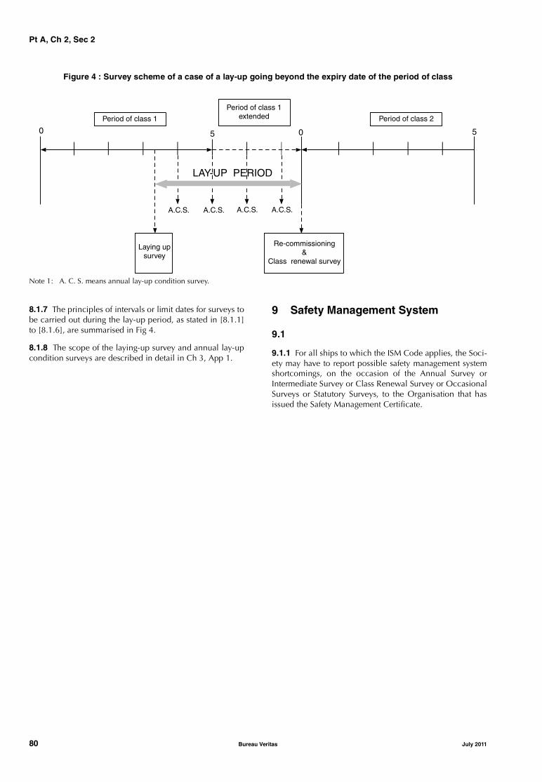
Pt A, Ch 2, Sec 2
Figure 4 : Survey scheme of a case of a lay-up going beyond the expiry date of the period of class
Note 1: A. C. S. means annual lay-up condition survey.
8.1.7 The principles of intervals or limit dates for surveys tobe carried out during the lay-up period, as stated in [8.1.1]to [8.1.6], are summarised in Fig 4.
8.1.8 The scope of the laying-up survey and annual lay-upcondition surveys are described in detail in Ch 3, App 1.
9 Safety Management System
9.1
9.1.1 For all ships to which the ISM Code applies, the Soci-ety may have to report possible safety management systemshortcomings, on the occasion of the Annual Survey orIntermediate Survey or Class Renewal Survey or OccasionalSurveys or Statutory Surveys, to the Organisation that hasissued the Safety Management Certificate.
Period of class 1
Period of class 1extended
0 05
A.C.S. A.C.S. A.C.S. A.C.S.
LAY-UP PERIOD
Laying upsurvey
Re-commissioning&
Class renewal survey
Period of class 2
5
80 Bureau Veritas July 2011
Pt A, Ch 2, Sec 3
SECTION 3 SUSPENSION AND WITHDRAWAL OF CLASS
1 General
1.1 Discontinuance of class
1.1.1 The class may be discontinued either temporarily orpermanently. In the former case it is referred to as “suspen-sion” of class, in the latter case as “withdrawal” of class. Inboth these cases, the class is invalidated in all respects. Inthe case of withdrawal, the name of the ship is deleted fromthe Register of Ships. The current version of the Register canbe consulted on the Society website.
1.2 Suspension of class
1.2.1 The class may be suspended either automatically orfollowing the decision of the Society. In any event, the shipwill be considered as not retaining its class from the date ofsuspension until the date when class is reinstated.
1.2.2 The class may be automatically suspended when oneor more of the following circumstances occur:
• when a ship is not operated in compliance with the rulerequirements, such as in cases of services or conditionsnot covered by the service notation, or trade outside thenavigation restrictions for which the class was assigned
• when a ship proceeds to sea with less freeboard thanthat assigned, or has the freeboard marks placed on thesides in a position higher than that assigned, or, in casesof ships where freeboards are not assigned, the draughtis greater than that assigned
• when the Owner fails to inform the Society in order tosubmit the ship to a survey after defects or damagesaffecting the class have been detected
• when repairs, alterations or conversions affecting theclass are carried out either without requesting theattendance of the Society or not to the satisfaction of theSurveyor. For voyage repairs, reference is to be made toCh 2, Sec 2, [2.9].
Suspension of class with respect to the above cases willremain in effect until such time as the cause giving rise tosuspension has been removed. Moreover, the Society mayrequire any additional surveys deemed necessary takinginto account the condition of the ship and the cause of thesuspension.
1.2.3 In addition, the class is automatically suspended:
• when the class renewal survey has not been completedby its limit date or within the time granted for the com-pletion of the survey, unless the ship is under attendanceby the Society’s Surveyors with a view to completionprior to resuming trading
• when the annual or intermediate surveys have not beencompleted by the end of the corresponding survey timewindow (see Ch 2, Sec 2, [2.1.3]) unless the ship isunder attendance for completion of the survey.
Continuous survey item(s) due or overdue at the time ofannual surveys is (are) to be dealt with. The ship's classwill be subject to a suspension procedure if the item(s)is (are) not surveyed or postponed by agreement withthe Society.
Suspension of class with respect to the above cases willremain in effect until such time as the class is reinstatedonce the due items and/or surveys have been dealt with.
1.2.4 In addition to the circumstances for which automaticsuspension may apply, the class of a ship may also be sus-pended following the decision of the Society:
• when a recommendation is not dealt with within thetime limit specified, unless it is postponed before thelimit date by agreement with the Society
• when one or more surveys are not held by their limitdates (see Ch 2, Sec 2, [2.1.4]) or the dates stipulated bythe Society also taking into account any extensionsgranted in accordance with the provisions of Part A
• when, due to reported defects, the Society considersthat a ship is not entitled to retain its class even on atemporary basis (pending necessary repairs or renewals,etc.)
• when the ship has not been maintained in proper condi-tion, as set forth in Ch 1, Sec 1, [3.3.2]
• in other circumstances which the Society will consideron their merits (e.g. in the event of non-payment of feesor where the Owner fails to render the ship available forthe occasional surveys as listed in Ch 2, Sec 2, [6.1.2].
Suspension of class decided by the Society takes effect fromthe date when the conditions for suspension of class are metand will remain in effect until such time as the class is rein-stated once the due items and/or surveys have been dealtwith.
1.3 Withdrawal of class
1.3.1 The Society will withdraw the class of a ship in thefollowing cases:
• at the request of the Owner
• as a rule, when the causes that have given rise to a sus-pension currently in effect have not been removedwithin six months after due notification of suspension tothe Owner
• when the ship is reported as a constructive total loss
• when the ship is lost
• when the ship is reported scrapped.
July 2011 Bureau Veritas 81
Pt A, Ch 2, Sec 3
Withdrawal of class may take effect from the date on whichthe circumstances causing such withdrawal occur.
The contract for the classification of the ship is terminatedas of right in the above cases.
The class is also withdrawn according to the provisions ofarticle 7 of the Marine Division General Conditions in caseof contract termination.
1.3.2 When the withdrawal of class of a ship comes intoeffect, the Society will:• forward the Owner written notice• delete the ship from the Register of Ships• notify the flag Administration
• make the information available to the Underwriters, attheir request.
1.4 Suspension / withdrawal of additional class notations
1.4.1 If the survey requirements related to maintenance ofadditional class notations are not complied with, the sus-pension or withdrawal may be limited to the notations con-cerned.
The same procedure may apply to service notations of shipswhich are assigned with more than one service notation.
1.4.2 The suspension or withdrawal of an additional classnotation or a service notation (where a ship is assigned withmore than one service notation) generally does not affectthe class.
82 Bureau Veritas July 2011
Pt A, Ch 2, App 1
APPENDIX 1 PLANNED MAINTENANCE SURVEY SYSTEM
1 General
1.1
1.1.1 A Planned Maintenance Survey system (hereafterreferred to as PMS) is a survey system for machinery itemswhich may be considered as an alternative to the Continu-ous Survey for Machinery system (hereafter referred to asCSM), as described in Ch 2, Sec 2, [4.4].
1.1.2 This survey scheme is to be approved by the Societybefore being implemented. When the PMS system isapplied, the scope and periodicity of the class renewal sur-vey are tailored for each individual item of machinery anddetermined on the basis of recommended overhauls stipu-lated by the manufacturers, documented experience of theoperators and, where applicable and fitted, condition moni-toring. For instance, within the scope of a PMS system thefollowing cases may occur:
• switchboard A is surveyed based on the regular expirydate of the class renewal survey
• lubricating oil pump B is surveyed based on CSM scopeand periodicity
• diesel engine C is surveyed based on running hours
• turbo pump D is surveyed based on condition monitor-ing.
1.1.3 In general, the survey intervals for items surveyedunder the PMS system should not exceed those specified forthe CSM. However, for components where the maintenanceis based on running hours, longer intervals may be acceptedas long as the intervals are based on the manufacturer’s rec-ommendations. If an approved condition monitoring systemis in effect, the machinery survey intervals based on theCSM system may also be extended.
1.1.4 The Chief Engineer shall be the responsible person onboard in charge of the PMS.
The conditions related to Chief Engineer's inspectionswithin the scope of PMS are given in Ch 2, App 2.
Items surveyed by this authorised Chief Engineer will besubject to the confirmatory survey as detailed in Ch 2, App2.
Documentation on overhauls of items covered by the PMSare to be reported and signed by the Chief Engineer.
1.1.5 The conditions and procedures for the approval of aPMS are indicated in [2].
2 Conditions and procedures for the approval of the system
2.1 General
2.1.1 The PMS is to be approved by the Society. To this endthe Owner is to make a formal request to the Society andprovide the documentation and information specified in[2.2], combined in a manual describing the proposedscheme and including sample copies of the different docu-ments to be used during the implementation of the scheme.The PMS is to be programmed and maintained by a compu-terized system. However, this may not be applied to the cur-rent already approved schemes.
2.1.2 When using computerised systems, access for updat-ing of the maintenance documentation and the mainte-nance programmes is only granted to the personresponsible for the PMS or another person authorised byhim.
The computerised systems are to include a back-up proce-dure, which is to be activated at regular intervals.
The functional application of these systems is to beapproved by the Society.
2.2 Documentation
2.2.1 The documentation to be submitted is the manualmentioned above, which is to include:
a) a description of the scheme and its application on boardas well as the proposed organisation chart identifyingthe areas of responsibility and the people responsiblefor the PMS on board
b) the list of items of machinery and components to beconsidered for classification in the PMS, distinguishingfor each the principle of survey periodicity used as indi-cated in [1.1.2]
c) the procedure for the identification of the items listed inb), which is to be compatible with the identification sys-tem adopted by the Society
d) the scope and time schedule of the maintenance proce-dures for each item listed in b), including acceptablelimit conditions of the parameters to be monitoredbased on the manufacturers’ recommendations or rec-ognised standards and laid down in appropriate preven-tive maintenance sheets
e) the original reference data, monitored on board, formachinery undergoing maintenance based on conditionmonitoring
July 2011 Bureau Veritas 83

Pt A, Ch 2, App 1
f) the list and specifications of the condition monitoringequipment, including the maintenance and conditionmonitoring methods to be used, the time intervals formaintenance and monitoring of each item and accepta-ble limit conditions
g) the document flow and pertinent filing procedure.
2.3 Information on board
2.3.1 The following information is to be available on board:
a) all the documentation listed in [2.2], duly updated
b) the maintenance instructions including routine tests andinspections for each item of machinery, as applicable(supplied by the manufacturer or by the shipyard)
c) the condition monitoring data of the machinery, includ-ing all data since the last dismantling and the originalreference data
d) reference documentation (trend investigation proce-dures etc.)
e) the records of maintenance performed, including condi-tions found, repairs carried out, spare parts fitted
f) the list of personnel on board in charge of the PMS man-agement.
2.4 List of items
2.4.1 Ships subject to the planned maintenance survey sys-tem are provided with lists of items to be surveyed underthis system, as indicated in [5.2.10].
3 Implementation of the system
3.1
3.1.1 When the documentation submitted has beenapproved and the PMS system has been implemented onboard and used for a sufficient period (which is not toexceed one year) so that all personnel become familiar withit, a survey is to be carried out in order to start the systemand make it officially operational. The scope of this survey,referred to as Implementation Survey, is given in [5.1.1].
3.1.2 Upon the successful outcome of the ImplementationSurvey, the PMS is considered approved. The relevantannex to the Certificate of Classification of the ship isupdated and the survey notation PMS is entered in the Reg-ister of Ships.
4 Retention and withdrawal of the system
4.1
4.1.1 The PMS system is retained throughout the classperiod provided that:
• an annual report covering the year’s service is suppliedto the Society in accordance with [5.2.9]
• an annual audit in accordance with [5.2] is satisfactorilycompleted
• any change to the approved PMS is submitted to theSociety for agreement and approval.
4.1.2 The survey arrangement for machinery according tothe PMS may be withdrawn by the Society if the PMS is notsatisfactorily operated on account of either the maintenancerecords or the general condition of the machinery or thefailure to observe the agreed intervals between overhauls.
4.1.3 The Owner may discontinue the PMS at any time byinforming the Society in writing. In this case, the itemswhich have been inspected under the PMS since the lastannual audit will be credited for class at the discretion ofthe attending Surveyor.
4.1.4 In the case of sale or change of management of theship or classification after construction, the approval of thePMS will be reconsidered.
5 Surveys
5.1 Implementation survey
5.1.1 The implementation survey is to be carried out by aSurveyor of the Society, as stated in [3.1.1], within one yearfrom the date of the documentation approval.
5.1.2 The scope of this survey is to verify that:
• the PMS is implemented in accordance with theapproved documentation and is suitable for the typeand complexity of the components and systems onboard
• the documentation required for the annual audit is pro-duced by the PMS
• the requirements of surveys and testing for retention ofclass are complied with
• the shipboard personnel are familiar with the PMS pro-cedures.
Upon the successful outcome of the survey confirming theproper implementation of the PMS, the system is consideredoperational subject to the submission to the Society of areport describing the system.
5.2 Annual audit and confirmatory surveys
5.2.1 Once the PMS system is implemented, the continuedcompliance with the requirements for checks, overhaulsand repairs, where needed, indicated in [2] is to be verifiedby means of annual audits and confirmatory surveys inorder to confirm the validity of the approved survey schemesystem.
5.2.2 The annual audit and confirmatory surveys are to becarried out in conjunction with the annual class surveys.
5.2.3 The purpose of this audit is to verify that the schemeis being correctly operated, in particular that all items (to besurveyed in the relevant period) have actually been sur-veyed in due time. A general examination of the items con-cerned is carried out.
84 Bureau Veritas July 2011

Pt A, Ch 2, App 1
5.2.4 The maintenance and performance records are exam-ined to verify that the machinery has been functioning satis-factorily since the previous survey or audit or, if necessary,that the necessary measures have been taken in response tomachinery operating parameters exceeding acceptable tol-erances, and that the overhaul intervals have beenobserved.
5.2.5 Written reports of breakdown or malfunction are tobe made available.
5.2.6 The description of the repairs, if any, carried out is tobe examined. Any machinery part or component which hasbeen replaced by a spare due to damage is to be retainedon board, where possible. On this occasion such replacedparts are to be submitted to the examination of the Sur-veyor.
5.2.7 Where condition monitoring equipment is in use,functions tests, confirmatory surveys and random checkreadings are to be carried out as far as practicable and rea-sonable, at the discretion of the Surveyor.
5.2.8 The Surveyor also checks that the personnel on boardin charge of the PMS have the appropriate authorisation(see Ch 2, App 2).
5.2.9 An annual report covering the year’s service is to besupplied to the Society. It is to include the following infor-mation:
• the list of items of machinery and components (item b)in [2.2.1]) and the procedures for their identification
• the preventive maintenance sheets
• the condition monitoring data, including all data sincethe last dismantling and the original reference data ofthe machinery checked trough condition monitoring
• any changes to the other documentation in [2.2.1]
• full trend analysis (including spectrum analysis forvibrations) of machinery displaying operating parame-ters exceeding acceptable tolerances.
The Surveyor is to review this annual report or verify that ithas been reviewed by the Society.
5.2.10 The Surveyor carries out a confirmatory survey ofthe items which have been surveyed by the Chief Engineerand decides which items can be credited for maintenanceof machinery items classification, on the PMS list of items.
5.2.11 Upon the satisfactory outcome of this audit, the Sur-veyor confirms the validity of the PMS by endorsing the Cer-tificate of Classification in accordance with Ch 2, Sec 2,[3.3].
5.3 Damage and repairs
5.3.1 Damage to components or items of machinery cov-ered by the PMS which may affect the class is to be reportedto the Society. Where applicable, a Surveyor will attend onboard, survey the damaged items and, on the basis of thesurvey results, decide whether recommendations are to beimposed.
5.3.2 All parts of machinery or components which need toundergo substantial repairs are to be surveyed before, dur-ing and after the repairs, as deemed appropriate by the Sur-veyor. Any repair and corrective action regardingmachinery under PMS system shall be recorded in the PMSlogbook.
5.3.3 In the case of overdue recommendations or recordsof unrepaired damage which may affect the PMS, the rele-vant items are to be taken out of the PMS until the recom-mendations have been fulfilled or the repairs carried out.
6 Machinery items surveyed on the basis of condition monitoring
6.1
6.1.1 The extent of condition-based maintenance and asso-ciated monitoring equipment to be included in the mainte-nance scheme is decided by the Owner. The minimumparameters to be checked in order to monitor the conditionof the various machinery for which this type of maintenanceis accepted are indicated in [6.1.2] to [6.1.6].
6.1.2 For electric propulsion motor the parameters to bechecked are the following, as applicable:
• vibrations and noise of electric motor where applicable
• temperature of windings
• temperature of built-in coolers
• temperature of bearings
• temperature of cooling air
• insulation measurement
• winding resistance
• speed of electric motor
• current of electric motor
• voltage of electric motor in each phase
• current on field windings if applicable.
6.1.3 For the main diesel engine the parameters to bechecked are the following:
• power output
• rotational speed
• indicator diagram (where possible)
• fuel oil temperature and/or viscosity
• charge air pressure
• exhaust gas temperature for each cylinder
• exhaust gas temperature before and after the turbo-chargers
• temperatures and pressure of engine cooling systems
• temperatures and pressure of engine lubricating oil sys-tem
• rotational speed of turbochargers
• vibrations of turbochargers
• results of lubricating oil analysis
• crankshaft deflection readings
• temperature of main bearings.
July 2011 Bureau Veritas 85

Pt A, Ch 2, App 1
6.1.4 For the main and auxiliary steam turbines the param-eters to be checked are the following:
• turbine bearing vibrations
• power output• rotational speed
• plant performance data, i.e. steam conditions at theinlet and outlet of each turbine, saturated, superheatedand desuperheated steam conditions at the outlet ofboilers, condenser vacuum, sea temperature.
6.1.5 For the auxiliary diesel engines the parameters to bechecked are the following:• exhaust gas temperature before and after the turbo-
chargers
• temperatures and pressure of engine cooling systems
• temperatures and pressure of engine lubricating oil sys-tem
• rotational speed of turbochargers
• crankshaft deflection readings.
6.1.6 For other auxiliary machinery the parameters to bechecked are the following, as applicable:
• inlet and outlet temperatures of cooling systems
• inlet and outlet temperatures of heating systems
• vibrations and performance data of pumps and fans
• differential pressure at filters.
86 Bureau Veritas July 2011
Pt A, Ch 2, App 2
APPENDIX 2 CSM AND PMS SYSTEMS: SURVEYS CARRIED OUT BY THE CHIEF ENGINEER
1 Conditions
1.1
1.1.1 The basic conditions for the acknowledgment of sur-veys carried out by Chief Engineers are specified hereafter.Consideration may be given to other conditions on a caseby case basis.
1.1.2 An Owner's attestation, confirming that the ChiefEngineer is duly qualified to carry out the inspection of themachinery items when the CSM system or PMS system, asapplicable, is implemented on-board ships in accordancewith the requirements in [2.1.1] and [2.1.2], is to be madeavailable to the Surveyor on-board.
2 Limits of the interventions
2.1
2.1.1 For ships where the CSM system is implemented, thefollowing items of the class renewal survey for machinerycannot be inspected by the Chief Engineer:
• pressure vessels
• main and auxiliary turbines
• main reduction gears
• crankshafts, with associated main bearings and bottomend connecting rod bearings, of main propulsion inter-nal combustion engines. However, bottom end connect-ing rod bearings of diesel engines having trunk pistonsmay be inspected by the Chief Engineer when the com-plete associated cylinder is inspected in the course ofthe engine maintenance program
• turbochargers of main propulsion internal combustionengines
• intermediate shafting and associated bearings.
Generally, within a 10-year cycle comprising two consecu-tive class cycles, all the items surveyed under CSM are to beinspected once by the Society’s Surveyors.
2.1.2 For ships where the PMS system is implemented, allitems covered by the system can be surveyed by the ChiefEngineer, with the exception of pressure vessels.
2.1.3 In no case may the surveys of tailshafts and boilers,which are items not included in the scope of the classrenewal survey, be carried out by the Chief Engineer.
3 Procedure for carrying out surveys
3.1 General
3.1.1 As regards the procedure for carrying out surveys, theOwner is to inform the Chief Engineer that surveys are to beconducted in accordance with the Rules of the Society and,specifically, the requirements for class renewal surveysrelated to machinery and systems contained in Ch 3, Sec 3,[3].
It is the responsibility of the ship’s Captain and Chief Engi-neer to decide the date and place for the survey of eachcomponent in order to avoid possible accidents (fireincluded) in the event of damage to the unit(s) remaining inservice.
Some guidelines for the Chief Engineer relevant to the dis-mantling and inspections of main components of themachinery installation are given below.
The items and/or machinery which, as a result of the sur-veys, are replaced due to wear, damage or defects, are to bekept on board until they are inspected by a Surveyor of theSociety.
3.2 Main diesel engines
3.2.1 The following items are to be surveyed as indicated:
• the top and bottom halves of the main bearings are to beremoved and inspected, and the clearances are to betaken, recorded and compared with the limits recom-mended by the engine builder
• the top and bottom halves of crankpin bearings are to beexamined, and the clearances are to be taken, recordedand compared with the limits recommended by theengine builder
• crankpins, journals and webs are to be examined forcrack detection, mainly at the fillets and in the vicinityof the lubricating oil holes
• crankshaft deflections are to be taken and recorded atregulars intervals, enabling verification of the trendwhen they are taken in the presence of the Society’s Sur-veyor. This operation is to be effected bearing in mindthat during the readings the journals are to be steady ontheir bearings
• other parts exposed to wear or operating incidents are tobe carefully examined and the results recorded. In par-ticular, the wear of liners is to be measured andrecorded.
July 2011 Bureau Veritas 87
Pt A, Ch 2, App 2
3.3 Auxiliary diesel engines
3.3.1 The survey generally consists of the complete dis-mantling of the engine and a careful examination of thoseitems most liable to be exposed to wear or operating inci-dents. In particular:
• crankshaft deflections and wear of cylinder liners are tobe measured
• the crankshaft is to be checked by means of dye pene-trant in way of fillets and lubricating oil holes
• all top halves of the main bearings together with at leasttwo bottom halves are to be dismantled
• crankcase explosion relief valves, if fitted, are to bechecked.
3.4 Reciprocating compressors
3.4.1 The survey is to include:
• the dismantling of pistons and valves for inspection
• the examination and testing of the nest of cooler tubes
• the verification of safety relief valves after reassembling.
3.5 Coolers, condensers, heaters
3.5.1 The survey is to include:
• the dismantling of the covers
• the examination of the nest of tubes
• the testing of the nest of tubes, if necessary.
3.6 Electrical switchboard
3.6.1 The survey is to include:
• the cleaning of the switchboard
• the verification of the connection assemblies, lockingdevice tightening and busbar tightening
• the examination of the condition of the circuit-breakers,switches and fuses
• the verification of the contacts and screens
• the checking of the measuring instruments, which are tobe re-calibrated or replaced, if inaccurate
• the insulation resistance test.
3.7 a.c. and d.c. generators
3.7.1 The survey is to include:
• the removal of protection plates and brush carriers
• the cleaning of field coils and armature windings
• the verification of proper contact of brushes, which areto be renewed if excessively worn
• the verification of commutators and sliprings
• the measurement of air gap clearances
• the checking of journals and bearings
• the insulation resistance test.
3.8 Other items (pumps, electric motors, etc.)
3.8.1 The survey is generally to include the complete dis-mantling for inspection of the main parts exposed to wearor operating incidents, such as bearings, casings, impellersand rotors.
4 Records of surveys carried out
4.1
4.1.1 The surveys carried out by the Chief Engineer are tobe recorded in the engine/machinery log-book and a surveyreport is to be prepared for each item surveyed.
The report is generally to be drawn up in English; however,for ships trading in specific restricted areas the use of thelanguage of the country concerned will be accepted.
The report may be provided in hard copy or using a compu-terised recording system.
4.1.2 The report is to indicate the following information:
• identification data:
- name of ship and register number
- name of Chief Engineer and Owner’s attestation
- date and place (port or voyage leg) of the survey
- reference of the item in the CSM or PMS list, anddescription of the item
• inspection conducted:
- the type of inspection carried out: visual externalexamination, internal examination after dismantling,overhaul
- readings performed, when applicable: clearances,measurements, working pressure, or other workingparameters of the equipment
- inspection findings: corrosion, fractures, pieces ofequipment worn out, broken or missing
• maintenance and repairs carried out and parts replaced
• results of tests performed after the inspection, such asworking test, pressure test.
For sake of completeness, other documentation such assketches, photos, measurement reports may be attached tothe report.
The report is to be signed by the Chief Engineer.
5 Confirmatory survey
5.1
5.1.1 A confirmatory survey, to be carried out by a Sur-veyor of the Society, is to be requested according to the fol-lowing principle:
• for ships under the CSM system, within a reasonablyshort time from the date of the surveys carried out by theChief Engineer, and, in any case, in the first port whichis under the jurisdiction of an Office of the Society
• for ships under the PMS system, at the next annual audit(see Ch 2, App 1, [5.2]).
88 Bureau Veritas July 2011

Pt A, Ch 2, App 2
5.1.2 The Surveyor is to be supplied with a copy of this sur-vey report and also shown the engine log-book.
5.1.3 The Surveyor carries out an external examination ofthe relevant items and parts replaced and, if applicable,attends running tests. If doubts arise, the Surveyor mayrequest dismantling as deemed necessary.
5.1.4 If the persons on board are authorized to survey themain engine crankshaft and bearings (see [2.1.2]), the Sur-veyor performs the following:• check of condition monitoring records (see Ch 2, App 1,
[6.1.3])• check of crankshaft deflection readings• check of bearing clearances (where possible)• checks for signs of wiped or broken white metal in the
crankcase or filters• check of the witness marks of shrink fits of crankshafts• check of the bedplate structure (inside and outside)• check that the condition of crankpins, journals and
associated bearings is duly recorded.
5.1.5 Where the confirmatory survey is performed with anabnormal delay, the inspection is to be more extensive and,if necessary, the due surveys are to be completely repeated.
5.1.6 The date of the execution of the surveys will beassumed to be the date of the confirmatory survey.
6 Suspension of the Chief Engineer’s authorization
6.1
6.1.1 Where the condition of the items surveyed by theChief Engineer as specified in his or her reports does notcorrespond to the findings of the attending Surveyor, theSociety may suspend the Chief Engineer’s authorization.
6.1.2 The Society may also suspend the Chief Engineer’sauthorization in case of doubt on the general maintenanceof the machinery installation.
July 2011 Bureau Veritas 89
Pt A, Ch 2, App 3
APPENDIX 3 THICKNESS MEASUREMENTS: EXTENT, DETERMINATION OF LOCATIONS, ACCEPTANCE CRITERIA
1 General
1.1 Aim of the Appendix
1.1.1 Thickness measurements are a major part of surveys tobe carried out for the maintenance of class, and the analysis ofthese measurements is a prominent factor in the determinationand extent of the repairs and renewals of the ship’s structure.
1.1.2 The Appendix is intended to provide Owners, compa-nies performing thickness measurements and the Society’sSurveyors with a uniform means with a view to fulfillingRule requirements for thickness measurements. In particular,it will enable all the above-mentioned parties to carry out:• the planning and preparation• the determination of extent and location, and• the analysis
of the thickness measurements in cooperation.
1.1.3 It is to be noted that this Appendix also takes intoaccount specific requirements for thickness measurementsrelevant to close-up surveys of ships which are subject tothe Enhanced Survey Program (ESP).
1.1.4 This Appendix is also to be used for the thicknessmeasurements of ships assigned the notation VerisSTAR-HULL SIS (see Ch 5, Sec 2 and Part E, Chapter 1). However,the acceptance criteria for thickness measurements specificto this notation are given in Pt E, Ch 1, Sec 1 which refers toCh 2, App 3 or Pt E, Ch 1, App 2 for items as deemedappropriate by the Society.
1.2 Scope of the Appendix
1.2.1 Separate Articles below provide the following infor-mation:• references to rule requirements and some additional
information on the extent of the thickness measure-ments to be performed during surveys according totypes of ships and related surveys (see [2])
• locations of the measurements for the main parts of theship (see [3])
• how to analyse the results of thickness measurements(see [4]).
Tables and sketches are also given to detail the above pointsaccording to the types of ships.
2 Rule requirements for the extent of measurements
2.1 General
2.1.1 For the maintenance of class, thickness measure-ments may be required during annual, intermediate andclass renewal surveys.
Tab 1 gives the references to the requirements for minimumthickness measurements indicated in Part A, Chapter 3 andPart A, Chapter 4 for each service notation and related tothe different types of surveys.
Some additional explanations are also given about thewording used in the Rules as well as the general principlesof the required thickness measurements during classrenewal surveys.
2.2 Class renewal survey: all ships except those submitted to ESP or equivalent
2.2.1 The thickness measurements required by the Rulesconsist of:
• systematic thickness measurements, i.e. measurementsof different parts of the structure, in order to assess theoverall and local strength of the ship
• measurements of suspect areas as defined in Ch 2, Sec2, [2.2.8]
• additional measurements on areas determined as affectedby substantial corrosion as defined in Ch 2, Sec 2,[2.2.7].
Table 1 : References to rule requirements related to thickness measurements
SERVICENOTATION
TYPE OF SURVEY
CLASS RENEWAL INTERMEDIATE ANNUAL
allservice notations
except thosein other rows
Ch 3, Sec 3, [2.5] and Ch 3, Sec 3,Tab 3: systematic measurementsand suspect areasWhere substantial corrosion isfound, the extent of thicknessmeasurements may be increasedto the Surveyor’s satisfaction, usingCh 3, Sec 3, Tab 4 as guidance
Ch 3, Sec 2, Tab 1: thickness meas-urements to be taken if deemed nec-essary by the SurveyorWhere substantial corrosion isfound, the extent of thickness meas-urements may be increased to theSurveyor’s satisfaction, using Ch 3,Sec 3, Tab 4 as guidance
Ch 3, Sec 1, [2.1.2]: areas of sub-stantial corrosion identified at pre-vious surveysWhere substantial corrosion isfound, the extent of thicknessmeasurements may be increased tothe Surveyor’s satisfaction, usingCh 3, Sec 3, Tab 4 as guidance
90 Bureau Veritas July 2011

Pt A, Ch 2, App 3
bulk carrier ESPbulk carrier BC-A ESPbulk carrier BC-B ESPbulk carrier BC-C ESPore carrier ESPcombination carrier/ OBO ESPcombination carrier/ OOC ESP
Ch 4, Sec 2, [4.1] and Ch 4, Sec 2,[4.6]: planning and generalrequirementsCh 4, Sec 2, Tab 8 and Ch 4, Sec 2,Tab 9: measurements of elementssubjected to close-up surveyCh 4, Sec 2, Tab 11: extent of sys-tematic thickness measurementsCh 4, Sec 2, Tab 12 to Ch 4, Sec 2,Tab 20, according to the differentlocations, where substantial corro-sion is found
• Ships 10 years of age or less:Ch 4, Sec 2, Tab 3 and Ch 4, Sec2, Tab 5 for cargo holdsCh 4, Sec 2, Tab 4 and Ch 4, Sec2, Tab 6 for salt water ballasttanksCh 4, Sec 2, Tab 12 to Ch 4, Sec2, Tab 20, according to the dif-ferent locations, where substan-tial corrosion is found
• Ships over 10 years of age:see references given for classrenewal survey
Ch 4, Sec 2, Tab 1 and Ch 4, Sec2, Tab 2 for cargo holds and whendeemed necessary by the Surveyor Ch 4, Sec 2, [2.3] for salt ballasttanks and when deemed neces-sary by the SurveyorCh 4, Sec 2, Tab 12 to Ch 4, Sec 2,Tab 20, according to the differentlocations, where substantial corro-sion is found
oil tanker ESPcombination carrier/ OBO ESPcombination carrier/ OOC ESP
Ch 4, Sec 3, [6.1] and Ch 4, Sec 3,[6.5]: planning and generalrequirementsCh 4, Sec 3, Tab 1 and Ch 4, Sec 3,Tab 2: measurements of elementssubjected to close-up surveyCh 4, Sec 3, Tab 3: extent of sys-tematic thickness measurementsCh 4, Sec 3, Tab 2 and Ch 4, Sec 3,Tab 5, according to the differentlocations, where substantial corro-sion is found
• Ships 10 years of age or less: Ch 4, Sec 3, [4.2] for salt ballasttanksCh 4, Sec 3, Tab 4 and Ch 4, Sec3, Tab 5, according to the differ-ent locations, where substantialcorrosion is found
• Ships over 10 years of age:see references given for classrenewal survey
Ch 4, Sec 3, [2.3] limited to saltballast tanks and when deemednecessary by the SurveyorCh 4, Sec 3, Tab 4 and Ch 4, Sec3, Tab 5, according to the differentlocations, where substantial corro-sion is found
chemical tanker ESP Ch 4, Sec 4, [6.1] and Ch 4, Sec 4,[6.5]: planning and generalrequirementsCh 4, Sec 4, Tab 1: measurementsof elements subjected to close-upsurveyCh 4, Sec 4, Tab 2: extent of sys-tematic thickness measurementsCh 4, Sec 4, Tab 3: according tothe different locations, where sub-stantial corrosion is found
• Ships 10 years of age or less: Ch 4, Sec 4, [4.2] for salt ballasttanksCh 4, Sec 4, Tab 3: according tothe different locations, wheresubstantial corrosion is found
• Ships over 10 years of age:see references given for classrenewal survey
Ch 4, Sec 4, [2.3] limited to saltballast tanks and when deemednecessary by the SurveyorCh 4, Sec 4, Tab 3: according tothe different locations, where sub-stantial corrosion is found
liquefied gas carrier Ch 4, Sec 5, [6.2], Ch 4, Sec 5,[6.3.2] and Ch 4, Sec 5, [6.5]:planning and general requirementsCh 4, Sec 5, Tab 2: measurementsof elements subjected to close-upsurveyCh 4, Sec 5, Tab 3: extent of sys-tematic thickness measurementsWhere substantial corrosion isfound, the extent of thicknessmeasurements may be increasedto the Surveyor’s satisfaction, usingCh 3, Sec 3, Tab 4 as guidance
Ch 4, Sec 5, Tab 1: thickness meas-urements to be taken if deemed nec-essary by the SurveyorWhere substantial corrosion isfound, the extent of thickness meas-urements may be increased to theSurveyor’s satisfaction, using Ch 3,Sec 3, Tab 4 as guidance
Ch 4, Sec 5, [2.5.2] limited to saltballast tanks and when deemednecessary by the SurveyorWhere substantial corrosion isfound, the extent of thicknessmeasurements may be increasedto the Surveyor’s satisfaction,using Ch 3, Sec 3, Tab 4 as guid-ance
general cargo ship Ch 4, Sec 7, [4.1], Ch 4, Sec 7,[4.2] and Ch 4, Sec 7, [4.5]: plan-ning and general requirementsCh 4, Sec 7, Tab 4: measurementsof elements subjected to close-upsurveyCh 4, Sec 7, Tab 5: extent of sys-tematic thickness measurementsWhere substantial corrosion isfound, the extent of thicknessmeasurements may be increasedto the Surveyor’s satisfaction, usingCh 4, Sec 7, Tab 6 as guidance
• Ships 15 years of age or less:Ch 4, Sec 7, Tab 2 for cargoholdsCh 4, Sec 7, Tab 3 for salt waterballast spacesCh 4, Sec 7, Tab 6, where sub-stantial corrosion is found
• Ships over 15 years of age:see references given for classrenewal survey
Ch 4, Sec 7, Tab 1 for cargo holdswhen deemed necessary by theSurveyor or where extensive cor-rosion exists Ch 4, Sec 7, [2.4] for ballast tankswhen deemed necessary by theSurveyor or where extensive cor-rosion existsCh 4, Sec 7, Tab 6 where substan-tial corrosion is found
SERVICENOTATION
TYPE OF SURVEY
CLASS RENEWAL INTERMEDIATE ANNUAL
July 2011 Bureau Veritas 91
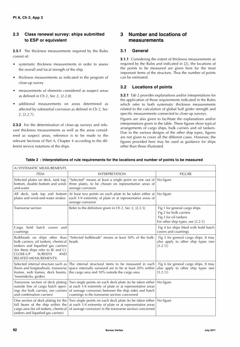
Pt A, Ch 2, App 3
2.3 Class renewal survey: ships submitted to ESP or equivalent
2.3.1 The thickness measurements required by the Rulesconsist of:
• systematic thickness measurements in order to assessthe overall and local strength of the ship
• thickness measurements as indicated in the program ofclose-up survey
• measurements of elements considered as suspect areasas defined in Ch 2, Sec 2, [2.2.8]
• additional measurements on areas determined asaffected by substantial corrosion as defined in Ch 2, Sec2, [2.2.7].
2.3.2 For the determination of close-up surveys and rele-vant thickness measurements as well as the areas consid-ered as suspect areas, reference is to be made to therelevant Sections of Part A, Chapter 4 according to the dif-ferent service notations of the ships.
3 Number and locations of measurements
3.1 General
3.1.1 Considering the extent of thickness measurements asrequired by the Rules and indicated in [2], the locations ofthe points to be measured are given here for the mostimportant items of the structure. Thus the number of pointscan be estimated.
3.2 Locations of points
3.2.1 Tab 2 provides explanations and/or interpretations forthe application of those requirements indicated in the Ruleswhich refer to both systematic thickness measurementsrelated to the calculation of global hull girder strength andspecific measurements connected to close-up surveys.Figures are also given to facilitate the explanations and/orinterpretations given in the table. These figures show typicalarrangements of cargo ships, bulk carriers and oil tankers.Due to the various designs of the other ship types, figuresare not given to cover all the different cases. However, thefigures provided here may be used as guidance for shipsother than those illustrated.
Table 2 : Interpretations of rule requirements for the locations and number of points to be measured
A) SYSTEMATIC MEASUREMENTS
ITEM INTERPRETATION FIGURE
Selected plates on deck, tank top,bottom, double bottom and wind-and-water
“Selected” means at least a single point on one out ofthree plates, to be chosen on representative areas ofaverage corrosion
No figure
All deck, tank top and bottomplates and wind-and-water strakes
At least two points on each plate to be taken either ateach 1/4 extremity of plate or at representative areas ofaverage corrosion
No figure
Transverse section Refer to the definition given in Ch 2, Sec 2, [2.2.5] Fig 1 for general cargo ships Fig 2 for bulk carriers Fig 3 for oil tankersFor other ship types, see [3.2.1]
Cargo hold hatch covers andcoamings
Fig 4 for ships fitted with hold hatchcovers and coamings
Bulkheads on ships other thanbulk carriers, oil tankers, chemicaltankers and liquefied gas carriers(for these ships refer to B) and C):CLOSE-UP SURVEYS ANDRELATED MEASUREMENTS)
“Selected bulkheads” means at least 50% of the bulk-heads
Fig 5 for general cargo ships. It mayalso apply to other ship types (see[3.2.1])
Selected internal structure such asfloors and longitudinals, transverseframes, web frames, deck beams,‘tweendecks, girders
The internal structural items to be measured in eachspace internally surveyed are to be at least 20% withinthe cargo area and 10% outside the cargo area
Fig 6 for general cargo ships. It mayalso apply to other ship types (see[3.2.1])
Transverse section of deck platingoutside line of cargo hatch open-ings (for bulk carriers, ore carriersand combination carriers)
Two single points on each deck plate (to be taken eitherat each 1/4 extremity of plate or at representative areasof average corrosion) between the ship sides and hatchcoamings in the transverse section concerned
No figure
One section of deck plating for thefull beam of the ship within thecargo area (for oil tankers, chemicaltankers and liquefied gas carriers)
Two single points on each deck plate (to be taken eitherat each 1/4 extremity of plate or at representative areasof average corrosion) in the transverse section concerned
No figure
92 Bureau Veritas July 2011

Pt A, Ch 2, App 3
B) CLOSE-UP SURVEYS AND RELATED MEASUREMENTS (for oil tankers, chemical tankers, gas carriers and combination carriers)
ITEM INTERPRETATION FIGURE
Web frame ring(for oil tankers and combinationcarriers)
Refer to the definition given in Ch 4, Sec 3, Tab 1.“Adjacent structural members” means plating and stiff-eners of deck, bottom, double bottom, sides and longitu-dinal bulkheads in the vicinity of the web frame ring
Extent of areas is shown as � in Ch 4,Sec 3, Fig 1Locations of points are given in Fig 10
Transverse section(for chemical tankers and liquefiedgas carriers)
Refer to the definitions given in Ch 4, Sec 4, Tab 1 andCh 4, Sec 5, Tab 2.“Adjacent structural members” means plating and stiff-eners of deck, bottom, double bottom, sides and longitu-dinal bulkheads in the vicinity of the web frame ring
No figure
Deck transverse This is the upper part of the web frame ring including theadjacent structural members (see meaning given above).For chemical tankers it may be fitted on deck, i.e. outsidethe tank
Extent of areas is shown as � in Ch 4,Sec 3, Fig 1Locations of points are given in Fig 10
Deck and bottom transverses(for oil tankers)
Refer to the definition given in Ch 4, Sec 3, Tab 1 Extent of areas is shown as � and �in Ch 4, Sec 3, Fig 1Locations of points are given in Fig 10
Transverse bulkhead “Complete” means the whole bulkhead including string-ers and stiffeners and adjacent structural members asdefined above
Extent of areas is shown as � in Ch 4,Sec 3, Fig 1Locations of points are given in Fig 11
“Lower part” means lower part of bulkhead up to 1/4 ofship’s depth or 2 metres above the lower stringer, which-ever is the greater (stringers, stiffeners and adjacentstructural members included)
Extent of areas is shown as � in Ch 4,Sec 3, Fig 1Locations of points are given in Fig 11
All plating and internal structures(for chemical tankers and liquefiedgas carriers)
Refer to the definitions given in Ch 4, Sec 4, Tab 1 andCh 4, Sec 5, Tab 2
No figure
C) CLOSE-UP SURVEYS AND RELATED MEASUREMENTS (for bulk and ore carriers)
ITEM INTERPRETATION FIGURE
Frames in cargo holds 25% of frames: one out of four frames should preferablybe chosen throughout the cargo hold length on each side“Selected frames” means at least 3 frames on each sideof cargo holds
Extent of areas is shown as � in Ch 4,Sec 2, Fig 1Locations of points are given in Fig 7
Transverse bulkheads in cargoholds
Refer to the definition given in Ch 4, Sec 2, Tab 8Two selected bulkheads: one is to be the bulkheadbetween the two foremost cargo holds and the secondmay be chosen in other positions
Areas of measurements are shown inCh 4, Sec 2, Fig 1Locations of points are given in Fig 8
One transverse bulkhead in eachcargo hold
This means that the close-up survey and related thick-ness measurements are to be performed on one side ofthe bulkhead; the side is to be chosen based on the out-come of the overall survey of both sides. In the event ofdoubt, the Surveyor may also require (possibly partial)close-up survey on the other side
Areas of measurements are shown inCh 4, Sec 2, Fig 1Locations of points are given in Fig 8
Transverse bulkheads in onetopside/side ballast tank
The ballast tank is to be chosen based on the history ofballasting among those prone to have the most severeconditions
Locations of points are given in Fig 9
Transverse webs in ballast tanks Either of the representative tanks of each type (i.e. topsideor hopper or side tank) is to be chosen in the forward part“Associated plating and longitudinals” means adjacentplating and longitudinals of deck, bottom, side shell,slope, hopper and longitudinal bulkhead, as applicable
Extent of areas is shown as � in Ch 4,Sec 2, Fig 1Locations of points are given in Fig 7
Areas of deck plating inside line ofhatch openings
“Selected” means at least a single point on one out ofthree plates, to be chosen on representative areas ofaverage corrosion“All deck plating” means at least two points on eachplate to be taken either at each 1/4 extremity of plate orat representative areas of average corrosion
Extent of areas is shown as � in Ch 4,Sec 2, Fig 1
July 2011 Bureau Veritas 93

Pt A, Ch 2, App 3
4 Acceptance criteria for thickness measurements
4.1 General
4.1.1 Acceptance criteria stipulate limits of wastage whichare to be taken into account for reinforcements, repairs orrenewals of steel structure. These limits are generallyexpressed for each structural item as a maximum percent-age of acceptable wastage (W). When the maximum per-centage of wastage is indicated, the minimum acceptablethickness (tmin) is that resulting from applying this percent-age to the rule thickness (trule), according to the followingformula:
However, when the rule thickness is not available, the as-built thickness can be used.
Only for criteria related to an item (see [4.3.4] b), the Soci-ety may establish a list of renewal thicknesses tailored to thedifferent structural items. In such a case these thicknessesare used in lieu of the minimum thicknesses calculatedfrom the percentage of wastage.
Note 1: In any case, at the request of the Owner, the Society mayperform a direct calculation based on the current measurements.
4.1.2 In cases where the ship has some structural elementswith reduced wear margins (e.g. due to ship conversion,increase of draught), the minimum acceptable thickness forthese elements is to be calculated with reference to the rulescantlings without taking account of any reduction origi-nally agreed.
4.1.3 Decisions on steel renewals are taken by the attend-ing Surveyor applying the criteria given in this Article andbased on his judgment and the actual condition of the ship.Should advice be needed to support his decision, the Sur-veyor may refer to the relevant technical office of the Soci-ety.
4.2 Criteria
4.2.1 The acceptance criteria for the minimum thicknessesare divided into:
• criteria on local and global strength, given in [4.3]
• criteria on buckling strength, given in [4.4]
• criteria on pitting, given in [4.5].
4.2.2 Each measured structural item is to be checkedagainst these four criteria, as far as applicable. When thecriteria are not met, reinforcements, repairs and renewalsare to be carried out as appropriate.
Figure 1 : Transverse section of a general cargo ship
Measurements are to be taken on both port and starboard sides of the selected transverse section
tmin 1 W100----------–
⎝ ⎠⎛ ⎞ trule=
$$$
$$
$$
$ $ $
$$
$
$ $
$ $
$
$
$
$
$ $
$
$
$ $
$
30 mm
94 Bureau Veritas July 2011

Pt A, Ch 2, App 3
Figure 2 : Transverse section of bulk carriers
Measurements are to be taken on both port and starboard sides of the selected transverse section
����
���� ��� �� �������
��� ��� �� �������
����
July 2011 Bureau Veritas 95

Pt A, Ch 2, App 3
Figure 3 : Transverse section of an oil tanker
Measurements are to be taken on both port and starboard sides of the selected transverse section
Figure 4 : Locations of measurements on hatch covers and coamings(valid for all ships fitted with hatch covers and coamings)
(1) Three sections at L/4, L/2, 3L/4 of hatch cover length, including:
• one measurement of each hatch cover plate and skirt plate
• measurements of adjacent beams and stiffeners
• one measurement of coaming plates and coaming flange, each side
(2) Measurements of both ends of hatch cover skirt plate, coaming plate and coaming flange
(3) One measurement of one out of three hatch coaming brackets and bars, on both sides and both ends
30 mm
1 1 1
L/4 L/2 3L/4
2
2
2
2
3
1
2 3
50 mm
$ $ $ $
96 Bureau Veritas July 2011

Pt A, Ch 2, App 3
Figure 5 : Locations of measurements on bulkheads of general cargo ships
Cargo hold bulkhead/watertight floor plating to be measured as per main view
One stiffener out of three to be measured as per view A - A
Figure 6 : Locations of measurements on selected internal structural elements of general cargo ships
30 m
m30
mm
30 mmA
A A - A
30 m
m
30 mm
30 m
m
30 mm
30 m
m
30 m
m
July 2011 Bureau Veritas 97

Pt A, Ch 2, App 3
Figure 7 : Locations of measurements on structural members in cargo holds and ballast tanks of bulk carriers
Figure 8 : Locations of measurements on cargo hold transverse bulkheads of bulk carriers
Measurements to be taken in each shaded area as per views A - A and B - B
30 mm
30 mm
A - A
xxx
xx
xx
xx
x
x
xx
x
x
x
x
xx
x
x
xx
xxx
x
x
x x
x
x
x
x
x
x
x
x
x
x
x
x
x
x
x
AA
Case without stoolsCase with stools
BB
A - A
B - B
A
A
98 Bureau Veritas July 2011

Pt A, Ch 2, App 3
4.3 Local and global strength criteria
4.3.1 Local and global strength criteria are given for the fol-lowing ship types:
• general cargo ships
• bulk carriers
• oil tankers.
These criteria may also be used for other ship types takinginto consideration the equivalence or similarity of structuralelements and their contribution to local and/or globalstrength.
4.3.2 For the evaluation of the ship longitudinal strength, itis a prerequisite that fillet welding between longitudinalmembers and deck, side and bottom plating is maintainedeffective so as to keep continuity of hull structures.
4.3.3 Each structural item to be assessed is illustrated in atypical transverse section (see Fig 13 for general cargoships, Fig 14 for bulk carriers, Fig 15 for oil tankers).
These structural items are also listed in a table (Tab 5 forgeneral cargo ships, Tab 6 for bulk carriers, Tab 7 for oiltankers) grouped according to their position and contribu-tion to the local or global strength of the ship.
4.3.4 Each structural item is to be assessed according tofour different criteria which vary with regard to the domainunder which it is considered, namely:
a) an isolated area, which is meant as a part of a singlestructural item. This criterion takes into considerationvery local aspects such as grooving of a plate or web, orlocal severe corrosion; however, it is not to be used forpitting for which separate criteria are considered (see[4.5])
b) an item, which is meant as an individual element suchas a plate, a stiffener, a web, etc. This criterion takes intoconsideration the average condition of the item, whichis assessed by determining its average thickness usingthe various measurements taken on the same item
Figure 9 : Locations of measurements on transverse bulkheads oftopside, hopper and double bottom tanks of bulk carriers
Measurements to be taken in each vertical section as per view A - A
���������
�� ��� ����� ��
���������� ��
�
�
���������
�� ��� ����� ��
���������� ��
�
�
������ � � �
July 2011 Bureau Veritas 99
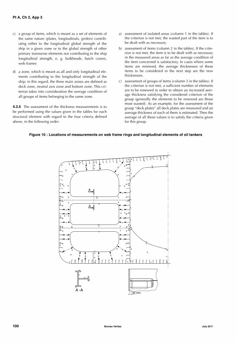
Pt A, Ch 2, App 3
c) a group of items, which is meant as a set of elements ofthe same nature (plates, longitudinals, girders) contrib-uting either to the longitudinal global strength of theship in a given zone or to the global strength of otherprimary transverse elements not contributing to the shiplongitudinal strength, e. g. bulkheads, hatch covers,web frames
d) a zone, which is meant as all and only longitudinal ele-ments contributing to the longitudinal strength of theship; in this regard, the three main zones are defined asdeck zone, neutral axis zone and bottom zone. This cri-terion takes into consideration the average condition ofall groups of items belonging to the same zone.
4.3.5 The assessment of the thickness measurements is tobe performed using the values given in the tables for eachstructural element with regard to the four criteria definedabove, in the following order:
a) assessment of isolated areas (column 1 in the tables). Ifthe criterion is not met, the wasted part of the item is tobe dealt with as necessary.
b) assessment of items (column 2 in the tables). If the crite-rion is not met, the item is to be dealt with as necessaryin the measured areas as far as the average condition ofthe item concerned is satisfactory. In cases where someitems are renewed, the average thicknesses of theseitems to be considered in the next step are the newthicknesses.
c) assessment of groups of items (column 3 in the tables). Ifthe criterion is not met, a sufficient number of elementsare to be renewed in order to obtain an increased aver-age thickness satisfying the considered criterion of thegroup (generally the elements to be renewed are thosemost wasted). As an example, for the assessment of thegroup “deck plates” all deck plates are measured and anaverage thickness of each of them is estimated. Then theaverage of all these values is to satisfy the criteria givenfor this group.
Figure 10 : Locations of measurements on web frame rings and longitudinal elements of oil tankers
A -A30 mm
A
A
100 Bureau Veritas July 2011
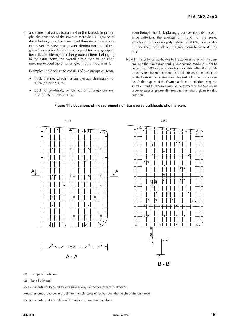
Pt A, Ch 2, App 3
d) assessment of zones (column 4 in the tables). In princi-ple, the criterion of the zone is met when all groups ofitems belonging to the zone meet their own criteria (seec) above). However, a greater diminution than thosegiven in column 3 may be accepted for one group ofitems if, considering the other groups of items belongingto the same zone, the overall diminution of the zonedoes not exceed the criterion given for it in column 4.
Example: The deck zone consists of two groups of items:
• deck plating, which has an average diminution of12% (criterion 10%)
• deck longitudinals, which has an average diminu-tion of 4% (criterion 10%).
Even though the deck plating group exceeds its accept-ance criterion, the average diminution of the zone,which can be very roughly estimated at 8%, is accepta-ble and thus the deck plating group can be accepted asit is.
Note 1: This criterion applicable to the zones is based on the gen-eral rule that the current hull girder section modulus is not tobe less than 90% of the rule section modulus within 0,4L amid-ships. When the zone criterion is used, the assessment is madeon the basis of the original modulus instead of the rule modu-lus. At the request of the Owner, a direct calculation using theship’s current thicknesses may be performed by the Society inorder to accept greater diminutions than those given for thiscriterion.
Figure 11 : Locations of measurements on transverse bulkheads of oil tankers
(1) : Corrugated bulkhead
(2) : Plane bulkhead
Measurements are to be taken in a similar way on the centre tank bulkheads
Measurements are to cover the different thicknesses of strakes over the height of the bulkhead
Measurements are to be taken of the adjacent structural members
A - AB - B
30 m
m
B
( 1 ) ( 2 )
A A
B
July 2011 Bureau Veritas 101
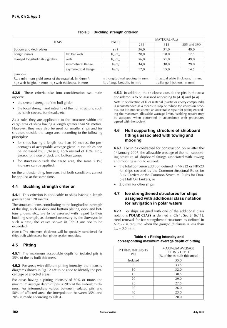
Pt A, Ch 2, App 3
Table 3 : Buckling strength criterion
4.3.6 These criteria take into consideration two mainaspects:
• the overall strength of the hull girder
• the local strength and integrity of the hull structure, suchas hatch covers, bulkheads, etc.
As a rule, they are applicable to the structure within thecargo area of ships having a length greater than 90 metres.However, they may also be used for smaller ships and forstructure outside the cargo area according to the followingprinciples:
• for ships having a length less than 90 metres, the per-centages of acceptable wastage given in the tables canbe increased by 5 (%) (e.g. 15% instead of 10%, etc.),except for those of deck and bottom zones
• for structure outside the cargo area, the same 5 (%)increase can be applied,
on the understanding, however, that both conditions cannotbe applied at the same time.
4.4 Buckling strength criterion
4.4.1 This criterion is applicable to ships having a lengthgreater than 120 metres.
The structural items contributing to the longitudinal strengthof the ship, such as deck and bottom plating, deck and bot-tom girders, etc., are to be assessed with regard to theirbuckling strength, as deemed necessary by the Surveyor. Insuch a case, the values shown in Tab 3 are not to beexceeded.
Note 1: The minimum thickness will be specially considered forships built with excess hull girder section modulus.
4.5 Pitting
4.5.1 The maximum acceptable depth for isolated pits is35% of the as-built thickness.
4.5.2 For areas with different pitting intensity, the intensitydiagrams shown in Fig 12 are to be used to identify the per-centage of affected areas.
For areas having a pitting intensity of 50% or more, themaximum average depth of pits is 20% of the as-built thick-ness. For intermediate values between isolated pits and50% of affected area, the interpolation between 35% and20% is made according to Tab 4.
4.5.3 In addition, the thickness outside the pits in the areaconsidered is to be assessed according to [4.3] and [4.4].Note 1: Application of filler material (plastic or epoxy compounds)is recommended as a means to stop or reduce the corrosion proc-ess, but it is not considered an acceptable repair for pitting exceed-ing the maximum allowable wastage limits. Welding repairs maybe accepted when performed in accordance with proceduresagreed with the society.
4.6 Hull supporting structure of shipboard fittings associated with towing and mooring
4.6.1 For ships contracted for construction on or after the1st January 2007, the allowable wastage of the hull support-ing structure of shipboard fittings associated with towingand mooring is not to exceed:• the total corrosion addition defined in NR522 or NR523
for ships covered by the Common Structural Rules forBulk Carriers or the Common Structural Rules for Dou-ble Hull Oil Tankers, or
• 2,0 mm for other ships.
4.7 Ice strengthened structures for ships assigned with additional class notation for navigation in polar waters
4.7.1 For ships assigned with one of the additional classnotations POLAR CLASS as defined in Ch 1, Sec 2, [6.11],steel renewal for ice strengthened structures as defined inNR527 is required when the gauged thickness is less thantnet + 0,5 mm.
Table 4 : Pitting intensity andcorresponding maximum average depth of pitting
ITEMS RATIOMATERIAL (ReH)
235 315 355 and 390Bottom and deck plates s / t 56,0 51,0 49,0Longitudinals flat bar web hw / tw 20,0 18,0 17,5
Flanged longitudinals / girders web hw / tw 56,0 51,0 49,0
symmetrical flange bf / tf 34,0 30,0 29,0
asymmetrical flange bf / tf 17,0 15,0 14,5
Symbols:ReH : minimum yield stress of the material, in N/mm2; hw : web height, in mm; tw : web thickness, in mm;
s : longitudinal spacing, in mm; bf : flange breadth, in mm;
t : actual plate thickness, in mm;tf : flange thickness, in mm;
PITTING INTENSITY(%)
MAXIMUM AVERAGEPITTING DEPTH
(% of the as-built thickness)Isolated 35,0
5 33,510 32,015 30,520 29,025 27,530 26,040 23,050 20,0
102 Bureau Veritas July 2011
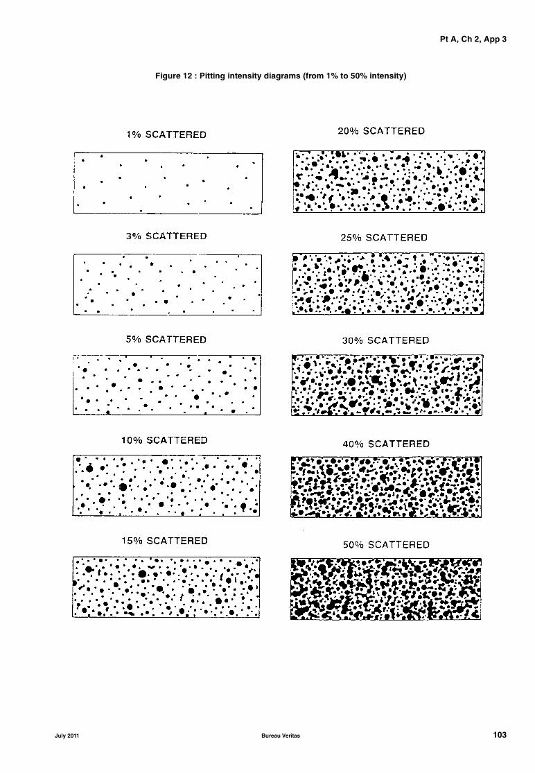
Pt A, Ch 2, App 3
Figure 12 : Pitting intensity diagrams (from 1% to 50% intensity)
July 2011 Bureau Veritas 103

Pt A, Ch 2, App 3
Figure 13 : General cargo ship: layout of items to be assessed
Table 5 : Local and global acceptance criteria for general cargo ships (given in % of wastage)
Group of items
Description of items1
Isolated area2
Item3
Group4
Zone
ITEMS CONTRIBUTING TO THE LONGITUDINAL STRENGTH (TRANSVERSE SECTION)
DECK ZONE (1) − − − 10
1 Hatch coamingunderdeck girder webunderdeck girder flange
−2520
−2015
10−−
−−−
2 Upperdeck plating, deck stringer plates and sheer strakes 30 20 10 −
3 Deck longitudinalswebflange
−3025
−2015
10−−
−−−
NEUTRAL AXIS ZONE (1) − − − 15
4 Side shell plating 25 20 15 −
5 ‘Tweendeck hatch girderwebflange
−2520
−2015
15−−
−−−
6 ‘Tweendeck plating 30 20 15 -
7 ‘Tweendeck longitudinalswebflange
−3025
−2015
15−−
−−−
4
520
19 21 11 129
18
10 8
14 16 13 15 1 2
17
2019
7
3
6
DECKZONE
NEUTRALAXISZONE
BOTTOMZONE
104 Bureau Veritas July 2011

Pt A, Ch 2, App 3
BOTTOM ZONE (1) − − − 10
8 Bilge and bottom strakes and keel plate 25 20 10 −
9 Bottom girders 25 20 10 −
10 Bilge and bottom longitudinalswebflange
−3025
−2015
10−−
−−−
11 Inner bottom plating 30 20 10 −
12 Inner bottom longitudinalswebflange
−3025
−2015
10−−
−−−
OTHER ITEMS
13 Hatch coaming plating (2) 25 20 − −
14 Hatch coaming brackets 30 25 − −
15 Hatch cover top plating (4) 25 20 15 −
16 Hatch cover skirt plating (4) 30 20 − −
17 Hatch cover stiffeners (4) 30 20 − −
18 Transverse bulkheads (3)platingstringer webstringer flangestiffener webstiffener flangebrackets
303025302530
202015201520
15−−−−−
−−−−−−
19 Side frameswebflangebrackets
302530
201520
−−−
−−−
20 Deck/’tweendeck beamswebflange
3025
2015
−−
−−
21 Floorsplating 30 20 − −
22 Forward and aft peak bulkheadsplatingstiffener webstiffener flange
303025
202015
15−−
−−−
(1) Each zone is to be evaluated separately.(2) If continuous, to be included in item 1.(3) For deep tank bulkheads, the values “average of item” and “average of group” are to be increased by 5 (%).(4) For cargo ships constructed (i.e. keel laid) from 1st January 2005:
• for single skin hatch covers and for the plating of double skin hatch covers, steel renewal is required where the gaugedthickness is less than (tnet + 0,5) mm. Where the gauged thickness is within the range (tnet + 0,5) mm and (tnet + 1) mm, coat-ing (applied in accordance with the coating manufacturer's requirements) or annual gauging may be adopted as an alterna-tive to steel renewal. Coating is to be maintained in good condition. If t net is not available, the as-built thickness minus thetotal corrosion addition can be used.
• for the internal structures of double skin hatch covers, thickness gauging is required when plating renewal is to be carriedout or when this is deemed necessary, at the discretion of the Society's Surveyor, on the basis of the plating corrosion ordeformation condition. In these cases, steel renewal for the internal structures is required when the gauged thickness is lessthan tnet. If tnet is not available, the as-built thickness minus the total corrosion addition can be used.
• for hatch covers in way of cellular cargo holds intended for containers (plating, stiffeners and internals), steel renewal isrequired where the gauged thickness is less than tnet. Where the gauged thickness is within the range tnet and (tnet + 0,5) mm,coating (applied in accordance with the coating manufacturer's requirements) or annual gauging may be adopted as analternative to steel renewal. Coating is to be maintained in good condition. If tnet is not available, the as-built thicknessminus the total corrosion addition can be used.
Group of items
Description of items1
Isolated area2
Item3
Group4
Zone
July 2011 Bureau Veritas 105

Pt A, Ch 2, App 3
106
Figure 14 : Bulk carrier: layout of items to be assessed
Table 6 : Local and global acceptance criteria for bulk carriers (given in % of wastage)
Group of items Description of items 1
Isolated area2
Item3
Group4
ZoneITEMS CONTRIBUTING TO THE LONGITUDINAL STRENGTH (TRANSVERSE SECTION)
DECK ZONE (1) − − − 101 Strength deck plating, deck stringer, sheer strake and part of
side shell plating in way of top side tanks25 20 10 −
2 Deck longitudinalswebflange
−2520
−2015
10−−
−−−
3 Side shell longitudinals in way of top side tankswebflange
−2520
−2015
10−−
−−−
4 Top side tank sloped plating, including horizontal and verti-cal strakes
25 20 10 −
5 Longitudinals connected to top side tank sloped platingwebflange
−2520
−2015
10−−
−−−
NEUTRAL AXIS ZONE (1) − − − 156 Side shell plating 25 20 15 −
BOTTOM ZONE (1) − − − 107 Bilge and bottom plating and keel plate 25 20 10 −8 Bilge and bottom longitudinals
webflange
−2520
−2015
10−−
−−−
9 Bottom girders 25 15 10 −10 Inner bottom plating and hopper tank sloped plating 25 20 10 −11 Longitudinals connected to inner bottom and hopper tank
sloped platingwebflange
−
2520
−
2015
10
−−
−
−−
DECKZONE
NEUTRAL AXIS ZONE
BOTTOM ZONE
6
7
4
17
9
8
1110
20
195
18
1
3
212161413 15
Bureau Veritas July 2011
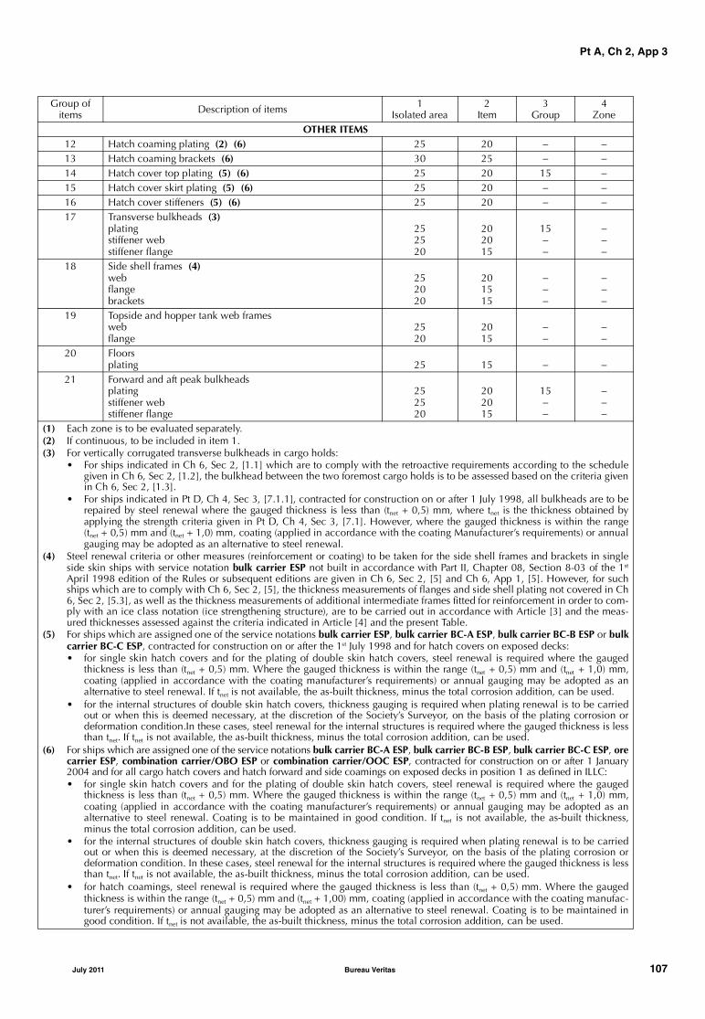
Pt A, Ch 2, App 3
OTHER ITEMS12 Hatch coaming plating (2) (6) 25 20 − −13 Hatch coaming brackets (6) 30 25 − −14 Hatch cover top plating (5) (6) 25 20 15 −15 Hatch cover skirt plating (5) (6) 25 20 − −16 Hatch cover stiffeners (5) (6) 25 20 − −17 Transverse bulkheads (3)
platingstiffener webstiffener flange
252520
202015
15−−
−−−
18 Side shell frames (4)webflangebrackets
252020
201515
−−−
−−−
19 Topside and hopper tank web frameswebflange
2520
2015
−−
−−
20 Floorsplating 25 15 − −
21 Forward and aft peak bulkheadsplatingstiffener webstiffener flange
252520
202015
15−−
−−−
(1) Each zone is to be evaluated separately.(2) If continuous, to be included in item 1.(3) For vertically corrugated transverse bulkheads in cargo holds:
• For ships indicated in Ch 6, Sec 2, [1.1] which are to comply with the retroactive requirements according to the schedulegiven in Ch 6, Sec 2, [1.2], the bulkhead between the two foremost cargo holds is to be assessed based on the criteria givenin Ch 6, Sec 2, [1.3].
• For ships indicated in Pt D, Ch 4, Sec 3, [7.1.1], contracted for construction on or after 1 July 1998, all bulkheads are to berepaired by steel renewal where the gauged thickness is less than (tnet + 0,5) mm, where tnet is the thickness obtained byapplying the strength criteria given in Pt D, Ch 4, Sec 3, [7.1]. However, where the gauged thickness is within the range(tnet + 0,5) mm and (tnet + 1,0) mm, coating (applied in accordance with the coating Manufacturer’s requirements) or annualgauging may be adopted as an alternative to steel renewal.
(4) Steel renewal criteria or other measures (reinforcement or coating) to be taken for the side shell frames and brackets in singleside skin ships with service notation bulk carrier ESP not built in accordance with Part II, Chapter 08, Section 8-03 of the 1st
April 1998 edition of the Rules or subsequent editions are given in Ch 6, Sec 2, [5] and Ch 6, App 1, [5]. However, for suchships which are to comply with Ch 6, Sec 2, [5], the thickness measurements of flanges and side shell plating not covered in Ch6, Sec 2, [5.3], as well as the thickness measurements of additional intermediate frames fitted for reinforcement in order to com-ply with an ice class notation (ice strengthening structure), are to be carried out in accordance with Article [3] and the meas-ured thicknesses assessed against the criteria indicated in Article [4] and the present Table.
(5) For ships which are assigned one of the service notations bulk carrier ESP, bulk carrier BC-A ESP, bulk carrier BC-B ESP or bulkcarrier BC-C ESP, contracted for construction on or after the 1st July 1998 and for hatch covers on exposed decks:• for single skin hatch covers and for the plating of double skin hatch covers, steel renewal is required where the gauged
thickness is less than (tnet + 0,5) mm. Where the gauged thickness is within the range (tnet + 0,5) mm and (tnet + 1,0) mm,coating (applied in accordance with the coating manufacturer’s requirements) or annual gauging may be adopted as analternative to steel renewal. If tnet is not available, the as-built thickness, minus the total corrosion addition, can be used.
• for the internal structures of double skin hatch covers, thickness gauging is required when plating renewal is to be carriedout or when this is deemed necessary, at the discretion of the Society’s Surveyor, on the basis of the plating corrosion ordeformation condition.In these cases, steel renewal for the internal structures is required where the gauged thickness is lessthan tnet. If tnet is not available, the as-built thickness, minus the total corrosion addition, can be used.
(6) For ships which are assigned one of the service notations bulk carrier BC-A ESP, bulk carrier BC-B ESP, bulk carrier BC-C ESP, orecarrier ESP, combination carrier/OBO ESP or combination carrier/OOC ESP, contracted for construction on or after 1 January2004 and for all cargo hatch covers and hatch forward and side coamings on exposed decks in position 1 as defined in ILLC:• for single skin hatch covers and for the plating of double skin hatch covers, steel renewal is required where the gauged
thickness is less than (tnet + 0,5) mm. Where the gauged thickness is within the range (tnet + 0,5) mm and (tnet + 1,0) mm,coating (applied in accordance with the coating manufacturer’s requirements) or annual gauging may be adopted as analternative to steel renewal. Coating is to be maintained in good condition. If tnet is not available, the as-built thickness,minus the total corrosion addition, can be used.
• for the internal structures of double skin hatch covers, thickness gauging is required when plating renewal is to be carriedout or when this is deemed necessary, at the discretion of the Society’s Surveyor, on the basis of the plating corrosion ordeformation condition. In these cases, steel renewal for the internal structures is required where the gauged thickness is lessthan tnet. If tnet is not available, the as-built thickness, minus the total corrosion addition, can be used.
• for hatch coamings, steel renewal is required where the gauged thickness is less than (tnet + 0,5) mm. Where the gaugedthickness is within the range (tnet + 0,5) mm and (tnet + 1,00) mm, coating (applied in accordance with the coating manufac-turer’s requirements) or annual gauging may be adopted as an alternative to steel renewal. Coating is to be maintained ingood condition. If tnet is not available, the as-built thickness, minus the total corrosion addition, can be used.
Group of items Description of items 1
Isolated area2
Item3
Group4
Zone
July 2011 Bureau Veritas 107

Pt A, Ch 2, App 3
Figure 15 : Oil tanker: layout of items to be assessed
Table 7 : Local and global acceptance criteria for oil tankers (given in % of wastage)
Group of items
Description of items1
Isolated area2
Item3
Group4
Zone
ITEMS CONTRIBUTING TO THE LONGITUDINAL STRENGTH (TRANSVERSE SECTION)
DECK ZONE (1) − − − 10
1 Deck plating, deck stringer, sheer strake and longitudinal bulkhead upper strake (2)
25 20 10 −
2 Deck and sheer strake longitudinalswebflange
−2520
−2015
10−−
−−−
3 Deck longitudinal girderswebflange
−2520
−2015
10−−
−−−
4 Longitudinals connected to long. bulkhead upper strake (2)webflange
−2520
−2015
10−−
−−−
NEUTRAL AXIS ZONE (1) − − − 15
5 Side shell plating (2) 25 20 15 −
6 Side shell longitudinals and stringers (2)webflange
−2520
−2015
15−−
−−−
7 Longitudinal bulkhead plating 25 20 15 −
8 Longitudinal bulkhead longitudinals and stringerswebflange
−2520
−2015
15−−
−−−
ZONE
BOTTOM ZONE
NEUTRAL AXIS
DECK ZONE
23
11
5
9
86
14
12 10
718
16
17
15
14
13
108 Bureau Veritas July 2011
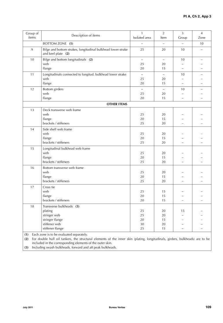
Pt A, Ch 2, App 3
BOTTOM ZONE (1) − − − 10
9 Bilge and bottom strakes, longitudinal bulkhead lower strake and keel plate (2)
25 20 10 −
10 Bilge and bottom longitudinals (2)webflange
−2520
−2015
10−−
−−−
11 Longitudinals connected to longitud. bulkhead lower strakewebflange
−2520
−2015
10−−
−−−
12 Bottom girderswebflange
−2520
−2015
10−−
−−−
OTHER ITEMS
13 Deck transverse web framewebflangebrackets / stiffeners
252025
201520
−−−
−−−
14 Side shell web framewebflangebrackets / stiffeners
252025
201520
−−−
−−−
15 Longitudinal bulkhead web framewebflangebrackets / stiffeners
252025
201520
−−−
−−−
16 Bottom transverse web framewebflangebrackets / stiffeners
252025
201520
−−−
−−−
17 Cross tiewebflangebrackets / stiffeners
252020
151515
−−−
−−−
18 Transverse bulkheads (3)platingstringer webstringer flangestiffener webstiffener flange
2525203025
2020152015
15−−−−
−−−−−
(1) Each zone is to be evaluated separately.(2) For double hull oil tankers, the structural elements of the inner skin (plating, longitudinals, girders, bulkheads) are to be
included in the corresponding elements of the outer skin. (3) Including swash bulkheads, forward and aft peak bulkheads.
Group of items
Description of items1
Isolated area2
Item3
Group4
Zone
July 2011 Bureau Veritas 109

Pt A, Ch 2, App 3
110 Bureau Veritas July 2011
Part AClassification and Surveys
Chapter 3
SCOPE OF SURVEYS (ALL SHIPS)
SECTION 1 ANNUAL SURVEY
SECTION 2 INTERMEDIATE SURVEY
SECTION 3 CLASS RENEWAL SURVEY
SECTION 4 BOTTOM SURVEY
SECTION 5 TAILSHAFT SURVEY
SECTION 6 BOILER SURVEY
SECTION 7 HULL SURVEY FOR NEW CONSTRUCTION
APPENDIX 1 CLASS REQUIREMENTS AND SURVEYS OF LAID-UP SHIPS
July 2011 Bureau Veritas 111

112 Bureau Veritas July 2011
Pt A, Ch 3, Sec 1
SECTION 1 ANNUAL SURVEY
1 General
1.1
1.1.1 The requirements of this Section apply to annual sur-veys of all ships. The specific requirements for annual sur-veys related to service notations and additional classnotations assigned to ships are addressed in Part A, Chapter4 and Part A, Chapter 5, respectively.
Note 1: Ships assigned with the service notation yacht and havinga length less than 24 m are not submitted to annual surveys for hulland machinery.
1.1.2 At the time of annual surveys, the ship is to be gener-ally examined. The survey is to include a visual inspectionof the hull, equipment and machinery of the ship and sometests thereof, so far as necessary and practicable in order toverify that the ship is in a acceptable general condition andis properly maintained.
1.1.3 Owners are reminded that, in compliance with therequirements in Ch 2, Sec 2, [6.4], any modification to theship’s hull, equipment and machinery affecting its classifi-cation is to be made known to the Society.
2 Hull
2.1 Hull and hull equipment
2.1.1 The survey is to include a general external examina-tion and testing, where appropriate, of the following items,as applicable:
• outer shell plating above the waterline, relevant shelldoors and accessible parts of the rudder(s)
• plating of freeboard deck and exposed decks, super-structures, with their openings and means of closure
• cargo hatchways and other openings on exposed decks,with their coamings and their means of closure andsecuring arrangements (for details see [2.2])
• sidescuttles and deadlights, chutes and other openingswith their means of closure
• bulwarks, guard rails, freeing ports, gangways and life-lines, ladders
• scuppers and sanitary discharges, valves on dischargelines and their controls
• ventilators, air pipes, overflow pipes and gas vent pipes,with their means of closure and flame screens, whererequired
• flame screens on vents to all bunker tanks
• all air pipe heads installed on the exposed decks (i.e.those extending above the freeboard deck or superstruc-ture decks)
• weld connection between air pipes and deck plating
• fittings and appliances for timber deck cargoes, whereapplicable
• freeboard marks on the ship’s sides
• deck equipment such as lifeboat davit foundations, bol-lards, fairleads, hawse pipes, etc., masts and associatedrigging, including lightning conductors
• windlass and equipment of chain cables or wire ropesfor anchors
• watertight bulkheads, their watertight doors and associ-ated local and remote controls, and their watertight pen-etrations
• main and auxiliary steering arrangements, includingtheir associated equipment and control systems, andmanoeuvring gear
• fire divisions and fire doors, dampers in ventilationducts, means of closure of skylights and other openings
• confirmation that emergency escape routes fromaccommodation and service spaces are satisfactory
• accessible cargo holds, in particular in areas likely to bedamaged by cargo handling
• confirmation that the drainage from enclosed cargospaces situated on the freeboard deck is satisfactory
• engine room
• where fitted, helicopter deck and its supporting structure,safety net and arrangements for the prevention of sliding
• availability of loading manual
• availability of electronic loading instrument, whererequired, and verification with standard test
• availability of approved stability documentation.
Note 1: Due attention is also to be given to fuel oil piping passingthrough ballast tanks, which is to be pressure tested where doubtsarise.
2.1.2 Suspect areas identified at previous surveys are to beexamined. Thickness measurements are to be taken of theareas of substantial corrosion and the extent of thicknessmeasurements is to be increased to determine areas of sub-stantial corrosion, in accordance with the requirements ofCh 3, Sec 3, Tab 4. These extended thickness measurementsare to be carried out before the annual survey is credited ascompleted.
Note 1: These requirements are not applicable to cargo tanks of oiltankers, chemical tankers and double hull oil tankers surveyed inaccordance with the requirements of Ch 4, Sec 3 and Ch 4, Sec 4.
July 2011 Bureau Veritas 113

Pt A, Ch 3, Sec 1
2.1.3 Examination of ballast tanks when required as a con-sequence of the results of the class renewal survey andintermediate survey is to be carried out. When considerednecessary by the Surveyor, or where extensive corrosionexists, thickness measurement is to be carried out. If theresults of these thickness measurements indicate that Sub-stantial Corrosion is found, then the extent of thicknessmeasurements is to be increased to determine areas of sub-stantial corrosion, in accordance with the requirements ofCh 3, Sec 3, Tab 4. These extended thickness measurementsare to be carried out before the annual survey is credited ascompleted.
2.2 Hatch covers and coamings
2.2.1 The Owner or his representative is to declare to theattending Surveyor that no significant changes have beenmade to the hatch covers, hatch coamings and their securingand sealing devices without prior approval of the Society.
The survey of hatch covers and coamings is to include:
a) when fitted with portable covers, or wooden or steelpontoons, checking of the satisfactory condition, whereapplicable, of:
• wooden covers and portable beams, carriers orsockets for the portable beams, and their securingdevices
• steel pontoons
• tarpaulins
• cleats, battens and wedges
• hatch securing bars and their securing devices
• loading pads/bars and the side plate edge
• guide plates and chocks
• compression bars, drainage channels and drainpipes (if any)
b) when fitted with mechanically operated steel covers,checking of the satisfactory condition, as applicable, of:
• hatch covers
• tightness devices of longitudinal, transverse andintermediate cross junctions (gaskets, gasket lips,compression bars, drainage channels and, if any,drain pipes)
• clamping devices, retaining bars, cleating
• chain or rope pulleys
• guides
• guide rails and track wheels
• stoppers, etc.
• wires, chains, gypsies, tensioning devices
• hydraulic system essential to closing and securing
• safety locks and retaining devices
• the operation of hatch covers, by means of randomexamination: stowage and securing in open condi-tion, proper fit, locking and efficiency of sealing inclosed position, operational testing of hydraulic andpower components, wires, chains and link drives
c) checking of the satisfactory condition of hatch coamingplating and its stiffeners, where applicable.
3 Machinery and systems
3.1 General machinery installations
3.1.1 The survey of general machinery installations is tocover the following items:
• general examination of machinery and boiler spaceswith particular attention to the fire and explosion haz-ards; confirmation that emergency escape routes arepracticable and not blocked
• general examination of the machinery, steam, hydraulic,pneumatic and other systems and their associated fit-tings, for confirmation of their proper maintenance
• testing of the means of communication and order trans-mission between the navigating bridge and the machin-ery control positions and other control stations
• confirmation that the rudder angle indicator on thebridge is in working order
• examination, as far as practicable, of the bilge pumpingsystems and bilge wells, including operation of thepumps, remote reach rods and level alarms, where fitted
• visual examination of the condition of any expansionjoints in sea water systems
• external examination of pressure vessels other than boil-ers and their appurtenances, including safety devices,foundations, controls, relieving gear, high pressure pip-ing, insulation and gauges.
3.1.2 When the ship is equipped with a refrigerating plant(whether or not covered by an additional class notation),the annual survey is to include the external examination of:
• pressure vessels of the installation to the same extent asindicated in [3.1.1]
• refrigerant piping, as far as practicable
• for refrigerating machinery spaces using ammonia asrefrigerant:
- ventilation system including functional test
- water-spraying fire-extinguishing system; see [3.4.2]item d)
- bilge system including functional test
- electrical equipment, confirming its proper mainte-nance
- gas detection system
- breathing apparatus and protective clothing.
3.1.3 When the ship is equipped with thruster installations,the annual survey is to include:
• an external examination of the machinery installation
• an operating test of the complete installation.
3.1.4 For ships subject to compliance with the require-ments laid down in Ch 6, Sec 2, [6], or in Ch 6, Sec 4, [2],or in Pt B, Ch 2, Sec 1, [1.2.1] or in Pt B, Ch 2, Sec 1,[1.2.2], the annual survey is to include an examination anda test of the water ingress detection systems and of theiralarms at random.
114 Bureau Veritas July 2011

Pt A, Ch 3, Sec 1
3.1.5 For ships subject to compliance with the require-ments laid down in Ch 6, Sec 2, [7], or in Pt C, Ch 1, Sec10, [6.6.3], item e), the annual survey is to include anexamination and a test of the means for draining and pump-ing ballast tanks forward of the collision bulkhead andbilges of dry spaces any part of which extends forward ofthe foremost cargo hold, and of their controls.
3.2 Boilers
3.2.1 For main and auxiliary steam boilers, the annual sur-vey consists of an external examination of boilers and theirappurtenances, including safety devices, foundations, con-trols, relieving, high pressure and steam escape piping,insulation and gauges.
The annual survey is to include test of safety and protectivedevices and test of safety valve using its relieving gear.
For exhaust gas heated economizers, the safety valves are tobe tested by the Chief Engineer at sea within the annual sur-vey window. This test is to be recorded in the log book forreview by the attending Surveyor prior to crediting theAnnual Survey of Machinery.
3.2.2 For thermal oil heaters, a functional test while inoperation is to be carried out, during which the followingitems are checked:
• the heater for detection of leakages
• the condition of the insulation
• the operation of indication, control and safety devices
• the condition of remote controls for shut-off and dis-charge valves.
A satisfactory analysis of the quality of oil is to be madeavailable to the Surveyor.
3.2.3 For exhaust gas thermal oil heaters, in addition to therequirements of [3.2.2], a visual examination and a tight-ness testing to the working pressure of the heater tubes areto be carried out.
3.3 Electrical machinery and equipment
3.3.1 The survey of electrical machinery and equipment isto cover the following items:
• general examination, visually and in operation, as feasi-ble, of the electrical installations for power and lighting,in particular main and emergency generators, electricmotors, switchboards, switchgears, cables and circuitprotective devices, indicators of electrical insulationand automatic starting, where provided, of emergencysources of power
• checking, as far as practicable, the operation of emer-gency sources of power and, where they are automatic,also including the automatic mode.
3.3.2 The survey is also to cover the bridge control of pro-pulsion machinery, and related arrangements (alarms andsafety devices), when fitted.
The survey of an automated installation covered by an addi-tional class notation is detailed in Part A, Chapter 5.
3.4 Fire protection, detection and extinction
3.4.1 The survey of fire prevention and other generalarrangements is to cover the following items:
• checking that fire control plans are properly posted
• examination and testing, as feasible, of the operation ofmanual and/or automatic fire doors, where fitted
• checking, as far as practicable, that the remote controlsfor stopping fans and machinery and shutting off fuelsupplies in machinery spaces and, where fitted, theremote controls for stopping fans in accommodationspaces and the means of cutting off power to the galleyare in working order
• examination and testing of the closing arrangements ofventilators, funnel annular spaces, skylights, doorwaysand tunnel, where applicable
• examination, as far as practicable, and testing, as feasi-ble and at random, of the fire and/or smoke detectionsystems.
3.4.2 The operational readiness and maintenance of fire-fighting systems is to be checked. The survey requirementsfor all types of fire-fighting systems that are usually found onboard ships related either to machinery spaces or cargospaces or vehicle spaces or special category spaces or ro-rospaces or accommodation spaces, irrespective of the serv-ice notation assigned, are the following:
a) water fire system
• examination of the fire main system and confirma-tion that each fire pump including the emergencyfire pump can be operated separately so that the tworequired powerful jets of water can be producedsimultaneously from different hydrants, at any part ofthe ship whilst the required pressure is maintainedin the fire main
• checking that fire hoses, nozzles, applicators, span-ners and international shore connection (where fit-ted) are in satisfactory working condition andsituated at their respective locations
b) fixed gas fire-extinguishing system
• external examination of receivers of CO2 (or othergas) fixed fire-extinguishing systems and their acces-sories, including the removal of insulation for insu-lated low pressure CO2 containers
• examination of fixed fire-fighting system controls,piping, instructions and marking; checking for evi-dence of proper maintenance and servicing, includ-ing date of last system tests
• test of the alarm triggered before the CO2 is released
c) sprinkler system
• examination of the system, including piping, valves,sprinklers and header tank
• test of the automatic starting of the pump activatedby a pressure drop
• check of the alarm system while the above test iscarried out
July 2011 Bureau Veritas 115
Pt A, Ch 3, Sec 1
d) water-spraying system
• examination of the system, including piping, noz-zles, distribution valves and header tank
• test of the starting of the pump activated by a pres-sure drop (applicable only for machinery spaces)
e) fixed foam systems (low or high expansion)
• examination of the foam system
• test to confirm that the minimum number of jets ofwater at the required pressure in the fire main isobtained when the system is in operation
• checking the supplies of foam concentrate andreceiving confirmation that it is periodically tested(not later than three years after manufacture andannually thereafter) by the manufacturer or an agent
f) dry powder system
• examination of the dry powder system, including thepowder release control devices
• checking the supplies of powder contained in thereceivers and that it has maintained its originalsmoothness
• checking that the pressure of propelling inert gascontained in the relevant bottles is satisfactory.
3.4.3 As far as other fire-fighting equipment is concerned, itis to be checked that:
• semi-portable and portable fire extinguishers and foamapplicators are in their stowed positions, with evidenceof proper maintenance and servicing, and detection ofany discharged containers
• firemen's outfits and emergency escape breathingdevices (EEBDs) are complete and in satisfactory condi-tion and the cylinders of any required self-containedbreathing apparatus are suitably charged.
3.4.4 The fire-extinguishing systems for spaces containingpaint and/or flammable liquids and deep-fat cooking equip-ment in accommodation and service spaces are to be exam-ined.
3.4.5 Where a helideck is fitted, the helicopter facilities areto be checked, as far as appropriate:• drainage arrangements around the landing area• fire fighting appliances and arrangements (to be sur-
veyed as per [3.4.2], according to the equipmentinstalled
• overall examination of refuelling systems and hangarfacilities for cleanliness and absence of leaks, conditionof gutters and drainage arrangement.
3.5 General emergency alarm system
3.5.1 The general emergency alarm system is to be exam-ined and tested.
116 Bureau Veritas July 2011

Pt A, Ch 3, Sec 2
July 2011 Bureau Veritas 117
SECTION 2 INTERMEDIATE SURVEY
1 General
1.1
1.1.1 The requirements of this Section apply to intermedi-ate surveys of all ships. The specific requirements for inter-mediate surveys related to service notations and additionalclass notations assigned to ships are addressed in Part A,Chapter 4 and Part A, Chapter 5, respectively.
1.1.2 A survey planning meeting is to be held prior to thecommencement of the survey.
1.1.3 Concurrent crediting to both Intermediate Survey andClass Renewal Survey for surveys and thickness measure-ments of spaces are not acceptable.
1.1.4 The intermediate survey is to include examinationand checks on a sufficiently extensive part of the structureto show that the structures of the ship are in satisfactorycondition so that the ship is expected to operate until theend of the current period of class, provided that the ship isproperly maintained and other surveys for maintenance ofclass are duly carried out during this period.
2 Hull
2.1
2.1.1 The requirements given in Tab 1 for the survey andtesting of salt water ballast spaces, cargo holds (for drycargo ships to which the additional requirements in Ch 4,Sec 2 and Ch 4, Sec 7 do not apply) and cargo tanks (fornon-ESP tankers) are to be complied with.
Table 1 : Intermediate survey of hull (all ships)
ITEMAge of ship (in years at time of intermediate survey)
5 < age ≤ 10 10 < age ≤ 15 age > 15
SALT WATER BALLAST SPACES Representative ballast tanksinternally examinedThickness measurements, ifconsidered necessary by theSurveyor
All spaces internally examinedThickness measurements, ifconsidered necessary by theSurveyor
All spaces internally examinedThickness measurements, if con-sidered necessary by the SurveyorTightness of inner bottom platingof cargo holds in way of doublebottom salt water ballast tankschecked, if considered necessaryby the Surveyor
See (1) (2) (3) See (1) (3) See (1) (3)
CARGO HOLDS (dry cargoships, to which the additionalrequirements in Ch 4, Sec 2 andCh 4, Sec 7 do not apply)
Selected cargo holds internallyexamined
CARGO TANKS(non-ESP tankers)
Selected cargo tanks internallyexamined
Selected cargo tanks internallyexamined
(1) If such examinations reveal no visible structural defects, the examination may be limited to a verification that the corrosion pre-vention system remains effective.
(2) If there is no hard protective coating, soft or semi-hard coating or poor coating condition, the examination is to be extended toother ballast spaces of the same type.
(3) For ballast tanks, excluding double bottom ballast tanks, if there is no hard protective coating, soft or semi-hard coating or poorcoating condition and it is not renewed, the spaces in question are to be internally examined at annual intervals. When such conditions are found in water ballast double bottom tanks, the spaces in question may be examined at annual inter-vals.
Note 1: Due attention is also to be given to fuel oil piping passing through ballast tanks, which is to be pressure tested should doubtsarise.

Pt A, Ch 3, Sec 3
SECTION 3 CLASS RENEWAL SURVEY
1 General
1.1
1.1.1 The requirements of this Section apply to classrenewal surveys of all ships. The specific requirements forclass renewal surveys related to service notations and addi-tional class notations assigned to ships are addressed in PartA, Chapter 4 and Part A, Chapter 5, respectively.
1.1.2 A survey planning meeting is to be held prior to thecommencement of the survey.
1.1.3 Concurrent crediting to both Intermediate Survey andClass Renewal Survey for surveys and thickness measure-ments of spaces are not acceptable.
1.1.4 The class renewal survey is to include sufficientlyextensive examination and checks to show that the struc-tures, main and auxiliary machinery, systems, equipmentand various arrangements of the ship are in satisfactory con-dition or restored to such condition as to allow the ship tooperate for the new period of class of five years to beassigned, provided that the ship is properly maintained andoperated and other surveys for maintenance of class areduly carried out during this period.
The examinations of the hull are to be supplemented bythickness measurements and testing as required in [2.4] and[2.5], to ensure that the structural integrity remains effec-tive. The aim of the examination is to discover substantialcorrosion, significant deformation, fractures, damages orother structural deformation that may be present.
1.1.5 The Owner is to provide the necessary facilities toenable this class renewal survey. The conditions for surveyas detailed in Ch 2, Sec 2, [2.5] to Ch 2, Sec 2, [2.7] are tobe met.
1.1.6 When the ship is under the continuous survey systemfor hull or machinery, the scope of the class renewal surveyas described in this Section is carried out on a continuousbasis over the period of class according to the procedurelaid down in Ch 2, Sec 2, [4.3].
When the machinery installation is surveyed under thePlanned Maintenance System, a specific program of surveyreplaces the scope of the class renewal survey of machineryand systems as laid down in [3], according to the procedurelaid down in Ch 2, Sec 2, [4.4].
1.1.7 Upon completion of the class renewal survey, or atthe end of the period of class (if the relevant part of the shipis surveyed under the continuous survey system), a generalexamination of the ship having the same scope as that of anannual survey, as detailed in Ch 3, Sec 1, is to be carriedout for class renewal.
2 Hull and hull equipment
2.1 Bottom survey in dry condition
2.1.1 A bottom survey in dry condition is to be carried out,as detailed in Ch 3, Sec 4, [2], and in addition the require-ments given in [2.1.3] to [2.1.5] are to be complied with.
2.1.2 For ships of unusual characteristics or engaged onspecial services, means of underwater inspection equivalentto the bottom survey in dry condition may be considered asan alternative by the Society, particularly when a suitablehigh resistance paint is applied to the underwater portion ofthe hull or an approved system of impressed current forexternal cathodic protection is fitted.
2.1.3 Anchors, windlass(es) and chain cables are to beranged and examined, and the required complement andcondition are to be checked. When the ship is more than 5years old, chain cables are to be gauged.
Any length of chain cable which is found to be damaged orexcessively worn is to be renewed.
2.1.4 Sea valves and cocks are to be opened up for internalexamination.
2.1.5 Thickness measurements of the outer shell plating, asand if required within the scope of the related class renewalsurvey, are to be carried out (refer to [2.5]), if not alreadydone within 15 months before the end of class period.
2.2 Decks, hatch covers and equipment
2.2.1 Decks are to be examined, particular attention beinggiven to the areas where stress concentration or increasedcorrosion are likely to develop, such as hatch corners andother discontinuities of structure.
Deck erections such as hatch coamings, deckhouses andsuperstructures are to be examined.
The sheathing of wood-sheathed steel decks may beremoved, at the Surveyor’s discretion, in the case of doubtas to the condition of plating underneath.
Due attention is to be given to the examination in way ofend and side openings and related shell and inner doors.
2.2.2 The hatch covers and coamings are to be surveyed asfollows:
• a thorough survey of the items listed in Ch 3, Sec 1,[2.2] including close-up survey of hatch cover platingand hatch coaming plating, is to be carried out
118 Bureau Veritas July 2011
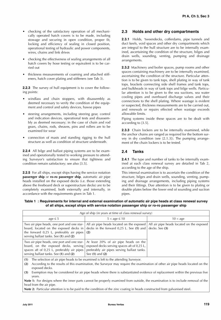
Pt A, Ch 3, Sec 3
• checking of the satisfactory operation of all mechani-cally operated hatch covers is to be made, includingstowage and securing in open condition, proper fit,locking and efficiency of sealing in closed position,operational testing of hydraulic and power components,wires, chains and link drives
• checking the effectiveness of sealing arrangements of allhatch covers by hose testing or equivalent is to be car-ried out
• thickness measurements of coaming and attached stiff-eners, hatch cover plating and stiffeners (see Tab 3).
2.2.3 The survey of hull equipment is to cover the follow-ing points:
• windlass and chain stoppers, with disassembly asdeemed necessary to verify the condition of the equip-ment and control and safety devices, hawse pipes
• steering arrangements, including steering gear, controland indication devices, operational tests and disassem-bly as deemed necessary; in the case of chain and rodgears, chains, rods, sheaves, pins and rollers are to beexamined for wear
• connection of masts and standing rigging to the hullstructure as well as condition of structure underneath.
2.2.4 All bilge and ballast piping systems are to be exam-ined and operationally tested to working pressure to attend-ing Surveyor’s satisfaction to ensure that tightness andcondition remain satisfactory; see also [3.5].
2.2.5 For all ships, except ships having the service notationpassenger ship or ro-ro passenger ship, automatic air pipeheads installed on the exposed decks (i.e. those extendingabove the freeboard deck or superstructure decks) are to becompletely examined, both externally and internally, inaccordance with the requirements given in Tab 1.
2.3 Holds and other dry compartments
2.3.1 Holds, ‘tweendecks, cofferdams, pipe tunnels andduct keels, void spaces and other dry compartments whichare integral to the hull structure are to be internally exam-ined, ascertaining the condition of the structure, bilges anddrain wells, sounding, venting, pumping and drainagearrangements.
2.3.2 Machinery and boiler spaces, pump rooms and otherspaces containing machinery are to be internally examined,ascertaining the condition of the structure. Particular atten-tion is to be given to tank tops, shell plating in way of tanktops, brackets connecting side shell frames and tank tops,and bulkheads in way of tank tops and bilge wells. Particu-lar attention is to be given to the sea suctions, sea watercooling pipes and overboard discharge valves and theirconnections to the shell plating. Where wastage is evidentor suspected, thickness measurements are to be carried out,and renewals or repairs effected when wastage exceedsallowable limits.Piping systems inside these spaces are to be dealt withaccording to [3.5].
2.3.3 Chain lockers are to be internally examined, whilethe anchor chains are ranged as required for the bottom sur-vey in dry condition (see [2.1.3]). The pumping arrange-ment of the chain lockers is to be tested.
2.4 Tanks
2.4.1 The type and number of tanks to be internally exam-ined at each class renewal survey are detailed in Tab 2,according to the age of the ship.This internal examination is to ascertain the condition of thestructure, bilges and drain wells, sounding, venting, pump-ing and drainage arrangements, including piping systemsand their fittings. Due attention is to be given to plating ordouble plates below the lower end of sounding and suctionpipes.
Table 1 : Requirements for internal and external examination of automatic air pipe heads at class renewal surveyof all ships, except ships with service notation passenger ship or ro-ro passenger ship
Age of ship (in years at time of class renewal survey)
age ≤ 5 5 < age ≤ 10 10 < age
Two air pipe heads, one port and one star-board, located on the exposed decks inthe forward 0,25 L, preferably air pipesserving ballast tanks. See (1) and (2)
All air pipe heads located on the exposeddecks in the forward 0,25 L. See (1) and(2)
All air pipe heads located on the exposeddecks. See (3)
Two air pipe heads, one port and one star-board, on the exposed decks, servingspaces aft of 0,25 L, preferably air pipesserving ballast tanks. See (1) and (2)
At least 20% of air pipe heads on theexposed decks serving spaces aft of 0,25 L,preferably air pipes serving ballast tanks.See (1) and (2)
(1) The selection of air pipe heads to be examined is left to the attending Surveyor.(2) According to the results of this examination, the Surveyor may require the examination of other air pipe heads located on the
exposed decks.(3) Exemption may be considered for air pipe heads where there is substantiated evidence of replacement within the previous five
years.Note 1: For designs where the inner parts cannot be properly examined from outside, the examination is to include removal of thehead from the air pipe.Note 2: Particular attention is to be paid to the condition of the zinc coating in heads constructed from galvanised steel.
July 2011 Bureau Veritas 119
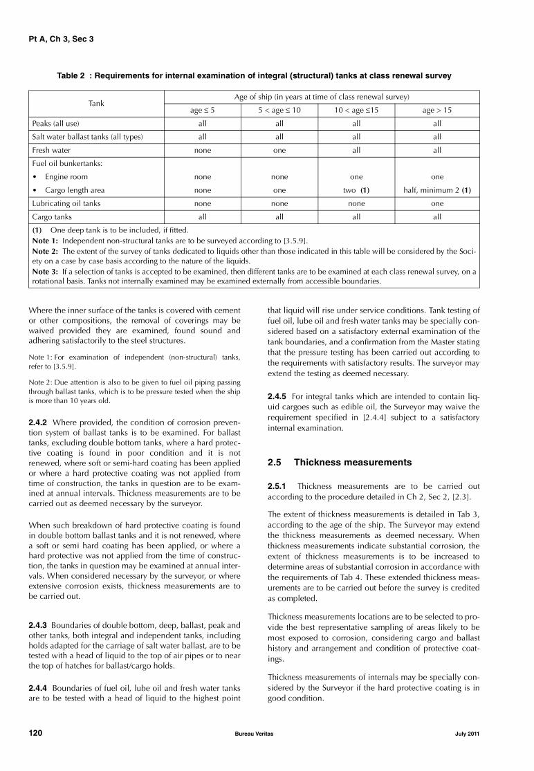
Pt A, Ch 3, Sec 3
Table 2 : Requirements for internal examination of integral (structural) tanks at class renewal survey
Where the inner surface of the tanks is covered with cementor other compositions, the removal of coverings may bewaived provided they are examined, found sound andadhering satisfactorily to the steel structures.
Note 1: For examination of independent (non-structural) tanks,refer to [3.5.9].
Note 2: Due attention is also to be given to fuel oil piping passingthrough ballast tanks, which is to be pressure tested when the shipis more than 10 years old.
2.4.2 Where provided, the condition of corrosion preven-tion system of ballast tanks is to be examined. For ballasttanks, excluding double bottom tanks, where a hard protec-tive coating is found in poor condition and it is notrenewed, where soft or semi-hard coating has been appliedor where a hard protective coating was not applied fromtime of construction, the tanks in question are to be exam-ined at annual intervals. Thickness measurements are to becarried out as deemed necessary by the surveyor.
When such breakdown of hard protective coating is foundin double bottom ballast tanks and it is not renewed, wherea soft or semi hard coating has been applied, or where ahard protective was not applied from the time of construc-tion, the tanks in question may be examined at annual inter-vals. When considered necessary by the surveyor, or whereextensive corrosion exists, thickness measurements are tobe carried out.
2.4.3 Boundaries of double bottom, deep, ballast, peak andother tanks, both integral and independent tanks, includingholds adapted for the carriage of salt water ballast, are to betested with a head of liquid to the top of air pipes or to nearthe top of hatches for ballast/cargo holds.
2.4.4 Boundaries of fuel oil, lube oil and fresh water tanksare to be tested with a head of liquid to the highest point
that liquid will rise under service conditions. Tank testing offuel oil, lube oil and fresh water tanks may be specially con-sidered based on a satisfactory external examination of thetank boundaries, and a confirmation from the Master statingthat the pressure testing has been carried out according tothe requirements with satisfactory results. The surveyor mayextend the testing as deemed necessary.
2.4.5 For integral tanks which are intended to contain liq-uid cargoes such as edible oil, the Surveyor may waive therequirement specified in [2.4.4] subject to a satisfactoryinternal examination.
2.5 Thickness measurements
2.5.1 Thickness measurements are to be carried outaccording to the procedure detailed in Ch 2, Sec 2, [2.3].
The extent of thickness measurements is detailed in Tab 3,according to the age of the ship. The Surveyor may extendthe thickness measurements as deemed necessary. Whenthickness measurements indicate substantial corrosion, theextent of thickness measurements is to be increased todetermine areas of substantial corrosion in accordance withthe requirements of Tab 4. These extended thickness meas-urements are to be carried out before the survey is creditedas completed.
Thickness measurements locations are to be selected to pro-vide the best representative sampling of areas likely to bemost exposed to corrosion, considering cargo and ballasthistory and arrangement and condition of protective coat-ings.
Thickness measurements of internals may be specially con-sidered by the Surveyor if the hard protective coating is ingood condition.
TankAge of ship (in years at time of class renewal survey)
age ≤ 5 5 < age ≤ 10 10 < age ≤15 age > 15
Peaks (all use) all all all all
Salt water ballast tanks (all types) all all all all
Fresh water none one all all
Fuel oil bunkertanks:
• Engine room none none one one
• Cargo length area none one two (1) half, minimum 2 (1)
Lubricating oil tanks none none none one
Cargo tanks all all all all
(1) One deep tank is to be included, if fitted.Note 1: Independent non-structural tanks are to be surveyed according to [3.5.9].Note 2: The extent of the survey of tanks dedicated to liquids other than those indicated in this table will be considered by the Soci-ety on a case by case basis according to the nature of the liquids. Note 3: If a selection of tanks is accepted to be examined, then different tanks are to be examined at each class renewal survey, on arotational basis. Tanks not internally examined may be examined externally from accessible boundaries.
120 Bureau Veritas July 2011
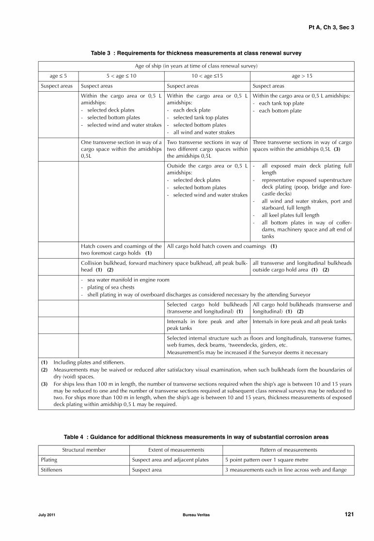
Pt A, Ch 3, Sec 3
Table 3 : Requirements for thickness measurements at class renewal survey
Table 4 : Guidance for additional thickness measurements in way of substantial corrosion areas
Age of ship (in years at time of class renewal survey)
age ≤ 5 5 < age ≤ 10 10 < age ≤15 age > 15
Suspect areas Suspect areas Suspect areas Suspect areas
Within the cargo area or 0,5 Lamidships:- selected deck plates- selected bottom plates- selected wind and water strakes
Within the cargo area or 0,5 Lamidships:- each deck plate- selected tank top plates- selected bottom plates- all wind and water strakes
Within the cargo area or 0,5 L amidships:- each tank top plate- each bottom plate
One transverse section in way of acargo space within the amidships0,5L
Two transverse sections in way oftwo different cargo spaces withinthe amidships 0,5L
Three transverse sections in way of cargospaces within the amidships 0,5L (3)
Outside the cargo area or 0,5 Lamidships: - selected deck plates- selected bottom plates- selected wind and water strakes
- all exposed main deck plating fulllength
- representative exposed superstructuredeck plating (poop, bridge and fore-castle decks)
- all wind and water strakes, port andstarboard, full length
- all keel plates full length- all bottom plates in way of coffer-
dams, machinery space and aft end oftanks
Hatch covers and coamings of thetwo foremost cargo holds (1)
All cargo hold hatch covers and coamings (1)
Collision bulkhead, forward machinery space bulkhead, aft peak bulk-head (1) (2)
all transverse and longitudinal bulkheadsoutside cargo hold area (1) (2)
- sea water manifold in engine room- plating of sea chests- shell plating in way of overboard discharges as considered necessary by the attending Surveyor
Selected cargo hold bulkheads(transverse and longitudinal) (1)
All cargo hold bulkheads (transverse andlongitudinal) (1) (2)
Internals in fore peak and afterpeak tanks
Internals in fore peak and aft peak tanks
Selected internal structure such as floors and longitudinals, transverse frames,web frames, deck beams, ‘tweendecks, girders, etc.Measurement5s may be increased if the Surveyor deems it necessary
(1) Including plates and stiffeners.(2) Measurements may be waived or reduced after satisfactory visual examination, when such bulkheads form the boundaries of
dry (void) spaces.(3) For ships less than 100 m in length, the number of transverse sections required when the ship’s age is between 10 and 15 years
may be reduced to one and the number of transverse sections required at subsequent class renewal surveys may be reduced totwo. For ships more than 100 m in length, when the ship’s age is between 10 and 15 years, thickness measurements of exposeddeck plating within amidship 0,5 L may be required.
Structural member Extent of measurements Pattern of measurements
Plating Suspect area and adjacent plates 5 point pattern over 1 square metre
Stiffeners Suspect area 3 measurements each in line across web and flange
July 2011 Bureau Veritas 121
Pt A, Ch 3, Sec 3
3 Machinery and systems
3.1 General
3.1.1 The survey items listed below are to be covered to thesatisfaction of the Surveyor. However, other survey alterna-tives deemed equivalent by the Surveyor in relation to thecharacteristics and general condition of the ship concernedmay also be accepted.
Note 1: Attention is drawn to the requirement Ch 2, Sec 2, [2.5.1]regarding safe execution of surveys, in particular as regards healthhazards related to asbestos.
3.2 Main and auxiliary engines and turbines
3.2.1 General
Depending on the type of machinery, the following partsare to be opened up as necessary for inspection. Parts andcomponents are to be pressure tested as appropriate or asdeemed necessary by the Surveyor. A working test is also tobe carried out, including testing of alarms and safetydevices.
3.2.2 Internal combustion engines
a) Columns and entablature
b) Cylinders with their liners, cylinder covers (togetherwith valves and valve gear), pistons with their rods,crossheads, slippers and guides (or gudgeon pins), con-necting rods (with their top and bottom end bearings),control gear, driven scavenge pumps, driven air com-pressors, driven fuel pumps, supercharging blowers, fuelinjection pumps, turning gear, etc.
c) Crankshafts (together with their main bearings)
d) Reverse gear, reduction gear and clutches, if fitted.
3.2.3 Steam turbines
a) Condensers and their cooling water and condensateextraction pumps
b) Casings and rotors (including their blading), impulsewheels (including guide blading and diaphragms), noz-zles and nozzle boxes, journals and bearings, dummypistons, labyrinths, external glands, etc.
c) Shafts, including their flexible couplings.
Where the propulsion steam turbines are of a well-knowntype, and fitted with rotor position indicators and vibrationindicators of an approved type, as well as measuring equip-ment of steam pressure at proper locations along the steamflow, and the arrangements for change-over in the event ofemergency operation of the plant are readily operable, thefirst class renewal survey may be limited to the examinationof rotor bearings, thrust bearings and flexible couplings,provided the Surveyor is satisfied from operation servicerecords and power trials subsequent to the survey, that theturbine plant is in good working condition.
3.2.4 Gas turbines
a) Casings, rotors and disks, impellers and blading of allturbines and compressors, combustion chambers, burn-ers, heat exchangers, gas piping, compressed air pipingwith fittings, starting and reverse arrangements
b) Shafts and their flexible couplings.
3.2.5 Electric propulsion
Where the propulsion machinery consists of an electricalsystem, the propulsion motors, generators, cables and allancillary electrical gear, exciters and ventilating plant(including coolers) associated therewith are to be examinedand the insulation resistance to earth tested. Due attentionis to be given to windings, commutations and sliprings. Theoperation of protective gear and alarm devices is to bechecked, as far as practicable. Interlocks intended to pre-vent unsafe operations or unauthorised access are to bechecked to verify that they are functioning correctly.
3.2.6 Thruster installations
When the ship is equipped with thruster installations, theclass renewal survey is also to include:
• an examination of the machinery and electrical installa-tion, as applicable
• an external examination of the propulsive part of theinstallation to be carried out at the dry dock survey dueas part of the class renewal survey. During this examina-tion other checks such as clearance readings, tightnessof hub and blade sealing for controllable pitch propel-lers are to be verified. Locking arrangements for bolts, iffitted, are to be checked. Results of lubricating oil analy-sis to detect possible deterioration of internal gears andbearings or the presence of water are to be confirmed asacceptable. The Manufacturer’s requirements may betaken into account. Dismantling of the assembly for theexamination of internal parts may be required if theforegoing checks are not satisfactory
• a running test of the system under operating conditions.
3.2.7 Pod propulsion systems
When the ship is equipped with pod propulsion systems,the class renewal survey is to include the examination of:
• electric propulsion motors and associated equipment,see [3.2.5]
• pod orientation device (gears and wheels, hydraulic/electric system, sealing arrangements)
• oil lubricating system of shaft bearings
• bilge system inside pod
• ventilation and cooling system
• rotating commutator
• alarm system.
122 Bureau Veritas July 2011
Pt A, Ch 3, Sec 3
3.3 Reduction gears, main thrust and intermediate shaft(s)
3.3.1 Reduction gears complete with all wheels, pinions,shafts, couplings, bearings and gear teeth, including incor-porated clutch arrangements, are to be opened up, asdeemed necessary by the Surveyor, for visual inspection.For complicated assemblies, gears and roller bearings maybe surveyed without dismantling.
3.3.2 All shafts, thrust blocks and bearings are to be exam-ined.
3.4 Pumps and other machinery items
3.4.1 GeneralThe items listed in [3.4.2] are to be opened up, as deemednecessary by the Surveyor, for visual inspection. Their partsand components are to be pressure tested as appropriateand considered necessary by the Surveyor. A working test isalso to be carried out, including testing of alarms and safetydevices if deemed necessary by the Surveyor.
3.4.2 Items to be surveyed
a) Air compressors with their intercoolers, filters and/or oilseparators and safety devices
b) Heat exchangers, ventilation fans for boilers and otherequipment used for essential services
c) Piston pumps and centrifugal pumps for sea water, bilgeand salt water ballast
d) Screw pumps, gear pumps and centrifugal pumps otherthan those listed in c) above (opening up is not required).
3.5 Systems in machinery spaces
3.5.1 Valves, cocks and strainers of the bilge and ballastsystems are to be opened up, as deemed necessary by theSurveyor, for visual inspection, and, together with the pip-ing and safety devices, examined and tested under workingconditions.
3.5.2 The fuel oil, lubricating oil, hydraulic oil, thermal oil,and feed and cooling water systems, together with pressurefilters, heaters and coolers used for essential services, are tobe opened up and examined or tested, as considered neces-sary by the Surveyor. Safety devices for the foregoing itemsare to be examined.
3.5.3 The compressed air system together with its valves,fittings and safety devices is to be examined, as considerednecessary by the Surveyor.
3.5.4 Compressed air receivers and other pressure vessels foressential services are to be cleaned internally and examinedinternally and externally. Their fittings, valves and safetydevices are to be opened up, as deemed necessary by the Sur-veyor, for visual inspection and pressure tested as appropriate.
3.5.5 Steel pipes for superheated steam having a tempera-ture of the steam at the superheater outlet exceeding 450°Care to be examined and tested in accordance with [3.5.7] to[3.5.8] at each class renewal survey.
3.5.6 Steel pipes for saturated steam or superheated steamhaving a temperature of the steam at the superheater outletnot exceeding 450°C are to be examined and tested inaccordance with [3.5.7] to [3.5.8] at each class renewalsurvey for ships over 5 years of age. When the ship is5 years of age or less, the inspection may be limited to acheck of the satisfactory general condition of pipes.
3.5.7 The examination and hydrostatic test of steel pipes formain steam machinery, and steel pipes for auxiliary steammachinery having internal diameter 75 mm and over, are tobe carried out on a number of pipes selected by the Sur-veyor after the lagging in way is removed.
3.5.8 Representative pipe lengths connected with boltedflanges are to be internally and externally examined, andhydrostatically tested to 1,1 times the working pressure atambient temperature. Bolts and butt-welded joints betweenflanges and pipes are to be submitted to a non-destructivetest for crack detection.
3.5.9 Non-structural tanks located in machinery spaces areto be externally examined; the relevant fittings, with partic-ular regard to the remote control shut-off valves underhydrostatic head, are to be externally examined to checkthe efficiency of manoeuvres and the absence of cracks orleakage.
3.5.10 When the ship is equipped with a refrigerating plant(whether or not covered by an additional class notation),the class renewal survey is to include:
• examination and test at the design pressure of the partsof the plant under pressure
• for refrigerating machinery spaces using ammonia asrefrigerant:
- examination and test of the water-spraying fire-extin-guishing system to the same extent as indicated in[3.8.3], item d)
- examination of valves and pumps of the bilge sys-tem to the same extent as indicated in [3.4]
- examination and test of the electrical equipment tothe same extent as indicated in [3.6.11]
- test of the gas detection system.
3.6 Electrical equipment and installations
3.6.1 An electrical insulation resistance test is to be per-formed on the electrical equipment and cables. If needed,for the purpose of this test, the installation may be subdi-vided or equipment which may be damaged disconnected.
3.6.2 The following minimum values, when performing theinsulation test, are to be considered:
• for main and emergency switchboards, feeder circuitbreakers being open, busbar circuit closed, measuringand monitoring instruments disconnected, the resist-ance of insulation measured across each insulated bus-bar and the hull, and across insulated busbars, shouldnot be less than 1 megohm
July 2011 Bureau Veritas 123

Pt A, Ch 3, Sec 3
• for generators, the equipment and circuits normallyconnected between the generator and the first circuitbreaker being connected, the resistance of insulation(preferably at working temperature whenever possible),in ohms, is to be greater than 1 000 times the rated volt-age, in volts. If appropriate, the Surveyor checks alsothat the insulation resistance of generators separateexciter gear is not less than 1 megohm
• the insulation resistance of the entire electrical system isto be checked with all circuit breakers and protectivedevices closed, except for generators; in general, theresistance should not be less than 100 000 ohms. How-ever, the variation of the resistance with time is to bechecked, comparing the current figure with previousreadings. If the insulation resistance was to drop sud-denly or be insufficient, the defective circuits are to betraced, disconnecting the circuits as much as necessary.
3.6.3 The prime movers of generators are to be surveyed inaccordance with [3.2] and their governors tested. All gener-ators are to be presented for inspection, clean and with cov-ers opened and examined under working conditions.
3.6.4 Main and emergency switchboards, section boardsand distribution boards are to be cleaned and doors or cov-ers opened for examination of their fittings. The condition ofovercurrent protective devices and fuses is to be checked.Circuit-breakers of generators are to be tested, as far aspracticable, to verify that protective devices including pref-erence tripping relays, if fitted, operate satisfactorily. It is tobe verified that there are no loose connections on busbar.
3.6.5 Electrical cables and cable runs are to be examinedat random, in particular in places where deterioration islikely to occur; terminal boxes of essential services are alsoto be subjected to a random check.
3.6.6 The motors and starters concerning essential servicestogether with associated control and switchgear are to beexamined and, if considered necessary by the Surveyor,checked, as far as practicable, under working conditions.
3.6.7 Navigation light indicators are to be tested underworking conditions, and correct operation on the failure ofsupply or failure of navigation lights verified.
3.6.8 The emergency sources of electrical power, theirautomatic arrangements and associated circuits are to betested.
3.6.9 Emergency lighting, transitional emergency lighting,supplementary emergency lighting, general emergencyalarm and public address systems are to be tested as far aspracticable.
3.6.10 The visible condition of electrical equipment andinstallations is also to be checked as regards precautionsagainst shock, fire and other hazards of electrical origin.
3.6.11 A general examination of the electrical equipmentin areas where there may be flammable gas or vapourand/or combustible dust is to be carried out to ensure thatthe integrity of the electrical equipment of a safety type hasnot been impaired owing to corrosion, missing bolts, etc.,and that there is not an excessive build-up of dust on or indust-protected electrical equipment. Cable runs are to beexamined for sheath and armouring defects, where practi-cable, and to ensure that the means of supporting the cablesare in satisfactory condition. The proper condition of bond-ing straps for the control of static electricity is to bechecked. Alarms and interlocks associated with pressurisedequipment or spaces are to be tested for correct operation.
Note 1: Owners are reminded that maintenance, repairs or renewalof certified electrical equipment of a safe type remains their respon-sibility or that of their representatives.
3.7 Controls
3.7.1 Where remote and/or automatic controls, not cov-ered by an additional class notation related to automatedinstallation, are fitted for essential machinery, they are to betested to demonstrate that they are in satisfactory condition.
3.8 Fire protection, detection and extinction
3.8.1 The Owner or his representative is to declare to theattending Surveyor that no significant changes have beenmade to the arrangement of structural fire protection.
Note 1: Attention is drawn to the provisions of Ch 1, Sec 1, [3.1.1]regarding compliance with any additional and/or more stringentrequirements issued by the Administration of the State whose flagthe ship is entitled to fly.
3.8.2 The class renewal survey of fire prevention arrange-ments is to cover the following items.
a) Visible parts of items forming part of structural fire pro-tection arrangements in accommodation spaces and inmachinery spaces such as bulkheads, decks, doors,stairways, crew and service lift trunks, and light and airtrunks are to be examined, due attention being given totheir integrity and that of the insulating material.
b) The operation of manual/automatic fire doors, where fit-ted, is to be checked.
c) Remote controls for stopping fans and machinery andshutting off fuel supplies in machinery spaces and,where fitted, remote controls for stopping fans inaccommodation spaces and means of automaticallyshutting off the electrical power of the deep-fat cookingequipment upon activation of the fire-extinguishing sys-tem are to be tested.
d) Closing arrangements of ventilators, funnel annularspaces, skylights, doorways and tunnels, where applica-ble, are to be tested.
e) Fire and/or smoke detection and alarm systems are to betested.
124 Bureau Veritas July 2011
Pt A, Ch 3, Sec 3
3.8.3 The survey requirements for all types of fire-fightingsystems that are usually found on board ships related eitherto machinery spaces or to cargo areas and/or spaces or toaccommodation spaces, irrespective of the service notationassigned, are the following:
a) water fire system
• the associated pumps are to be opened up andexamined at the Surveyor’s discretion
• the fire main is to be hydrostatically tested to theworking pressure at the Surveyor’s discretion
b) fixed gas fire-extinguishing system
Receivers of CO2 (or other gas) fixed fire-extinguishingsystems are to be externally examined together with allstationary fittings and devices. In addition, the followingapplies:
• the total loss of CO2 is not to exceed 10% of theinstalled quantity (5% for Halon)
• after being repaired or discharged, containers are tobe subjected to a hydrostatic test
• hydrostatic testing of high pressure CO2 containers isto be carried out at intervals not exceeding 10 years;the number of the tested containers is to be not lessthan 10% of the total number
• low pressure CO2 containers are to be internally sur-veyed if the content has been released and the con-tainer is older than five years; depending upon theresult of the internal examination, the Surveyor mayrequire the container to be hydrostatically tested.
It is to be checked that the distribution pipework isproved clear.
c) sprinkler system
• the associated pumps are to be opened up andexamined at the Surveyor’s discretion
d) water spraying system
• the associated pumps are to be opened up andexamined at the Surveyor’s discretion
• a working test is to be carried out as far as reasona-ble and appropriate
e) fixed foam systems (low or high expansion)
• the associated pumps are to be opened up andexamined at the Surveyor’s discretion
f) dry powder system• it is to be verified that the propelling inert gas bottles
have been hydrostatically tested. The same appliesto bottles disembarked for refilling or embarked forreplacement.
3.8.4 As far as other fire-fighting equipment is concerned,the following items are to be hydrostatically tested, at inter-vals not exceeding 10 years:• any CO2 bottles of extinguishers
• shells of foam extinguishers• shells of powder extinguishers• air or gas bottles associated with fire extinguishers
whose shells are not kept under pressure (if internallyexamined, the test need not be performed).
3.8.5 Where a helideck is fitted, the following is to bechecked, as far as appropriate:• drainage arrangements around the landing area• fire fighting appliances and arrangements (to be sur-
veyed as per [3.8.3] and [3.8.4], according to the equip-ment installed)
• other arrangements for helicopter refuelling and hangarfacilities (fuel system, ventilation, fire protection anddetection).
3.9 Hold, ballast and dry spaces water level detectors
3.9.1 For ships subject to compliance with the require-ments laid down in Ch 6, Sec 2, [6], or in Ch 6, Sec 4, [2],or in Pt B, Ch 2, Sec 1, [1.2.1] or in Pt B, Ch 2, Sec 1,[1.2.2], the class renewal survey is to include an examina-tion and a test of the water ingress detection systems and oftheir alarms.
3.10 Availability of pumping systems
3.10.1 For ships subject to compliance with the require-ments laid down in Ch 6, Sec 2, [7], or in Pt C, Ch 1, Sec10, [6.6.3], item e), the class renewal survey is to include anexamination and a test of the means for draining and pump-ing ballast tanks forward of the collision bulkhead andbilges of dry spaces any part of which extends forward ofthe foremost cargo hold, and of their controls.
July 2011 Bureau Veritas 125
Pt A, Ch 3, Sec 4
SECTION 4 BOTTOM SURVEY
1 General
1.1
1.1.1 Examinations of the outside of ship’s bottom andrelated items of ships is normally to be carried out with theship in dry-dock or on a slipway. However, considerationmay be given to alternate examination while the ship isafloat as an in-water survey, subject to provisions of Ch 2,Sec 2, [5.4] and [3] of this Section.
2 Bottom survey in dry condition
2.1 General requirements
2.1.1 When a ship is in dry-dock or on a slipway, it is to beplaced on blocks of sufficient height and with the necessarystaging to permit the examination of elements such as shellplating including bottom and bow plating, stern frame andrudder, sea chests and valves, propeller.
2.1.2 The shell plating is to be examined for excessive cor-rosion, or deterioration due to chafing or contact with theground or for any undue unfairness or buckling. Specialattention is to be paid to the connection between the bilgestrakes and the bilge keels and to the plating of end struc-tures (stem and sternframes). Important plate unfairness orother deterioration which do not necessitate immediaterepairs are to be recorded.
2.1.3 Sea chests and their gratings, sea connections andoverboard discharge valves and cocks and their fasteningsto the hull or sea chests are to be examined. Sea valves andcocks need not be opened up more than once in a classrenewal survey period unless considered necessary by theSurveyor.
2.1.4 Visible parts of the propeller(s), stern bush(es), pro-peller shaft boss, brackets and tightness system(s) are to beexamined. The clearances of the propeller shaft(s) (or weardown gauge) are to be checked and recorded. For controlla-ble pitch propellers, the Surveyor is to be satisfied with thefastenings and tightness of hub and blade sealing.
Visible parts of other propulsion systems and propellers forsteering purposes are also to be examined.
Dismantling is to be carried out, if considered necessary,notably where leakages are detected.
2.1.5 Visible parts of the rudder(s), rudder pintles, rudderstock and couplings as well as the sternframe are to beexamined. If considered necessary by the Surveyor, the rud-der(s) is (are) to be lifted or the inspection plates removedfor the examination of pintles.
The clearances in the rudder bearings and the rudder lower-ing are to be checked and recorded.
Where applicable, pressure test of the rudder may berequired as deemed necessary by the Surveyor.
2.2 Bottom survey held within the scope of class renewal survey
2.2.1 The examination and checks detailed in Ch 3, Sec 3,[2.1] are to be carried out as part of the class renewal sur-vey. They are usually carried out during the bottom surveyheld concurrently with the class renewal survey.
3 Bottom in-water survey
3.1 General
3.1.1 An in-water survey may normally be carried out if theship has been granted the additional class notation INWA-TERSURVEY as defined in Ch 1, Sec 2, [6.14.3]. Uponapplication by the Owner and in special circumstances, theSociety may also authorise such bottom in-water survey forships not assigned with the additional class notation INWA-TERSURVEY.
3.1.2 In principle, no outstanding recommendations are toexist requiring repair work to be carried out to the underwa-ter part of the shell plating, the rudder, the propeller or thepropeller shaft, unless the Society is satisfied that suchrepairs may be carried out while the ship is afloat.
3.1.3 Proposals for in-water survey are to be submitted inadvance of the survey by the Owner so that satisfactoryarrangements can be agreed with the Society.
The in-water survey is to be carried out with the ship at asuitable draught in sheltered water and preferably withweak tidal streams and currents. The in-water visibility is tobe good and the hull below waterline is to be sufficientlyclean to permit meaningful examination.
The equipment, procedure for observing and reporting thesurvey are to be discussed with the parties involved prior tothe in-water survey, and suitable time is to be allowed topermit the diving company to test all equipment before-hand.
126 Bureau Veritas July 2011

Pt A, Ch 3, Sec 4
3.1.4 The in-water survey is to be carried out by one ormore qualified divers under surveillance of a Surveyor. Thediver(s) is (are) to be employed by a firm approved as serv-ice supplier by the Society according to Ch 2, Sec 2, [2.4].
The Surveyor is to be satisfied with the methods of localisa-tion of the diver(s) on the plating, which should make usewhere necessary of permanent markings on the plating atselected points and with the method of pictorial representa-tion. An efficient two-way communication between the Sur-veyor and the diver(s) is to be provided.
3.1.5 The in-water survey is to provide the information nor-mally obtained from a bottom survey in dry condition. Spe-cial consideration shall be given to ascertaining rudder
bearing clearances and stern bush clearances of oil sternbearings based on a review of the operating history, onboard testing and stern oil sample reports. These considera-tions are to be included in the proposals for in-water surveyas required in [3.1.3].
Upon completion of the survey, the approved diving firm isto submit to the attending Society Surveyor a detailed reportincluding video tapes, as well as a photographic documen-tation of the main parts inspected.
3.1.6 If the in-water survey reveals damage or deteriorationthat requires immediate attention, the Surveyor may requirethat the ship be drydocked in order that a detailed surveycan be undertaken and the necessary repairs carried out.
July 2011 Bureau Veritas 127

Pt A, Ch 3, Sec 5
SECTION 5 TAILSHAFT SURVEY
1 Survey of tailshafts
1.1 General
1.1.1 The different types of surveys to which tailshafts maybe subjected and the intervals at which they are to be car-ried out are given in Ch 2, Sec 2, [5.5]. These surveys are:
• complete survey
• modified survey.
The requirements to be complied with at each survey arelisted in [1.2] and [1.3].
1.2 Complete survey
1.2.1 The complete survey of tailshafts consists of the fol-lowing, as applicable:
a) removal of propeller and key, where fitted, and theirexamination
b) complete withdrawal of shaft to permit the examinationof sterntube bearings (outboard or inboard dependingon the type of shaft)
c) examination by an appropriate crack detection methodof the after end of the cylindrical part of the shaft andforward one third of shaft cone, or the fillet of the flangein the case of a flanged coupling
Note 1: Refer also to Ch 2, Sec 2, [5.5.2], item b) where the crackdetection test of the aft flange fillet area may be dispensed withfor the solid flange couplings fitted at the end of the shaft.
d) examination of shaft bearing surfaces, liners, joints,threaded end and nut
e) examination of oil sealing glands with the necessary dis-mantling
f) measurements of clearances and/or weardown (prior toand after the survey) and their recording
g) opening-up of controllable pitch propellers and exami-nation of their working parts and control gear, if consid-ered necessary.
1.2.2 Where the notation MON-SHAFT has been assignedas specified in Ch 2, Sec 2, [5.5.4], the tailshaft need not bewithdrawn at the complete survey and items b) and d) of[1.2.1] need not be covered provided that all conditionmonitoring data (Aft bearing temperature, consumption andanalysis of lubricating oil) is found to be within permissiblelimits and the remaining requirements for the complete sur-vey are complied with.
Where the Surveyor considers that the data presented is notentirely to his satisfaction, the shaft is to be withdrawn.
1.3 Modified survey
1.3.1 A modified survey may be carried out for thosetailshafts which fulfil the conditions described in Ch 2, Sec2, [5.5.3], where the periodicity of this type of survey is alsoshown.
1.3.2 The modified survey for all types of shafts consists ofthe following:
• check of oil sealing glands in place
• measurements of weardown and their recording
• examination of the results of sterntube lubricating oilanalyses, to confirm they have been regularly performedand the recorded parameters are within acceptable lim-its
• check of the records of lubricating oil consumption, toconfirm it is within permissible limits.
In addition, for the different types of shafts, the following isrequired:
a) for shafts with keyed propeller coupling:
• removal of propeller and key, and their examinationin way of the connection area
• examination by an appropriate crack detectionmethod of the after end of the cylindrical part ofshaft and forward one third of shaft cone
b) for shafts with keyless type propeller coupling:
• check of the tightness of the propeller hub (propellerhood, fore gland)
c) for shafts with a solid flange coupling at the aft end andvariable pitch propeller:
• check of tightness in way of blade glands and distri-bution box
• check of analysis of hydraulic oil
• working test, as far as practicable, of the blademanoeuvring.
1.3.3 Where the Surveyor considers that the data presentedis not entirely to his satisfaction, further dismantling may berequired, including withdrawal of the tailshaft.
2 Periodical survey of other propulsion systems
2.1 Rotating and azimuth thrusters
2.1.1 The periodical survey of rotating and azimuth thrust-ers consists of:
128 Bureau Veritas July 2011

Pt A, Ch 3, Sec 5
a) removing the propeller(s) in order to examine the fol-lowing items, as applicable:
• exposed parts
• cone and keyway to be checked by an appropriatecrack detection method
• sealing glands
• threaded end and nut
b) examining the results of a lubricating oil analysis (watercontent and presence of material particles) to detectpossible deterioration of internal gears and bearings
c) examining the orientation device.
If the foregoing checks are not satisfactory, dismantling ofthe internal parts may be required.
2.2 Vertical axis propellers
2.2.1 The periodical survey of vertical axis propeller sys-tems consists of:
• checking the tightness of the oil glands and the backlashof the gears from outside by action on the blades
• checking the condition of gears and couplings frominside the ship
• examining the results of a lubricating oil analysis (watercontent and presence of material particles) to detectpossible deterioration of internal gears and bearings.
If the foregoing checks are not satisfactory, dismantling ofthe internal parts may be required.
2.3 Pump jet systems
2.3.1 The periodical survey of pump jet systems consists ofexamining the following parts: • impeller, shaft and clearances of bearings • tightness of gland • water duct • steering nozzle• reversing arrangements and control gear.
If the foregoing checks are not satisfactory, further disman-tling may be required.
2.4 Pod propulsion systems
2.4.1 The scope of complete and - where applicable- mod-ified survey of the pod propulsion system shafting arrange-ment is the one detailed in [1.2] and [1.3] for tailshafts.
2.4.2 Where the system is fitted with:• a vibration monitoring of roll bearings• a temperature monitoring of bearings, and• a monitoring of automatic bilge pumping system,
the shaft need not be withdrawn at the complete survey anditems b) and d) of [1.2.1] need not be covered provided thatall condition monitoring data (vibrations and temperaturesin way of bearings, consumption and analysis of lubricatingoil, running rate of bilge system) are found to be within per-missible limits and the remaining requirements for the com-plete survey are complied with.
Where the Surveyor considers that the data presented is notto his satisfaction, further dismantling are to be required.
July 2011 Bureau Veritas 129
Pt A, Ch 3, Sec 6
130 Bureau Veritas July 2011
SECTION 6 BOILER SURVEY
1 Steam boilers
1.1
1.1.1 Steam boilers, superheaters and economisers are tobe examined internally on water-steam side and fire sideand externally with the periodicity given in Ch 2, Sec 2,[5.6]. To this end, boilers are to be emptied and suitablyprepared for the examination, and the water-steam side andfire side are to be cleaned and cleared of soot. Where nec-essary, the external surfaces are to be made accessible forinspection by removal of insulation and lining.
1.1.2 Subject to the results of this visual examination, theSurveyor may require:
• non-destructive tests for detection of possible defects incritical areas of plating and shells, pipes and stays
• thickness measurements of plating and shells, furnaces,pipes and stays.
If appropriate, a new working pressure may be fixed by theSociety.
When situated inside boiler combustion chambers, steampipes of cylindrical boilers are to be examined at their ends,and if deemed necessary by the Surveyor, a sample pipe isto be removed for examination.
1.1.3 If the internal examination is not carried out for prac-ticable reasons, the parts subject to pressure are to be sub-mitted to a hydraulic test.
1.1.4 Boiler supports and securing arrangements (fixed andsliding seating, chocks, rolling stays, if any, etc.) are to beexamined.
Boiler accessories and mountings (such as valves and studs,water level indicators, safety valves) are to be examined ateach survey and opened out as considered necessary by theSociety.
Forced circulation pumps of fired steam generators are,wherever possible, to be opened up.
Fuel supply pipes between pumps and burners, fuel tankvalves, pipes and deck control gear are to be examined.
1.1.5 Upon completion of the internal survey, the boiler isto be examined under steam and fuel oil burners and safetydevices checked under working conditions.
The adjustment of the safety valves is to be verified duringeach boiler internal examination.
Boiler safety valve and its relieving gear are to be examinedand tested to verify satisfactory operation.
However, for exhaust gas heated economizers, if steam can-not be raised at port, it is the Chief Engineer’s responsibilityto set the safety valves at sea and the results are to berecorded in the log book for review by the Society.
1.1.6 Review of the following records since the last boilersurvey is to be carried out as part of the survey:
• operation
• maintenance
• repair history
• feedwater chemistry.
1.1.7 In addition to the above requirements, in exhaust gasheated economizers of the shell type, accessible weldedjoints are to be subjected to a visual examination for crack-ing. Non-destructive testing may be required for this purpose.
2 Thermal oil heaters
2.1
2.1.1 Thermal oil heaters are to be internally and externallyexamined. The heater tubes are to be visually examined,and the tightness of the installation (including flange con-nections, valves and pumps) is to be checked through a testat the working pressure.
2.1.2 Thermal oil heater supports and securing arrange-ments are to be examined.
Heater accessories and mountings are to be externally and(as needed) internally examined.
Forced circulation pumps are, wherever possible, to beopened up.
Fuel supply pipes between pumps and burners, fuel tankvalves, pipes and deck control gear are to be examined.
2.1.3 The following safety devices and instrumentation areto be examined and tested:
• thermal fluid temperature safety device and control
• thermal fluid flow meter
• device for low thermal fluid level in the expansion tank
• other regulation and safety systems.
2.1.4 Where repairs and/or renewal of componentsexposed to pressure are performed, a pressure test is to becarried out to 1,5 times the working pressure.
2.1.5 Upon completion of the survey, the thermal oil heateris to be examined under working conditions, with particularattention to safety devices and controls of the plant.
Pt A, Ch 3, Sec 7
SECTION 7 HULL SURVEY FOR NEW CONSTRUCTION
1 General
1.1
1.1.1 In this Section, the Shipbuilder is understood as act-ing directly or on behalf of the Party requesting classifica-tion.
1.1.2 When a hull construction is surveyed by the Societythe Shipbuilder is to provide all appropriate evidencerequired by the Society that the hull is built in compliancewith the rules and regulations, taking account of the rele-vant approved drawings.
2 Documentation to be available for the Surveyor during construction
2.1
2.1.1 During the construction, the Shipbuilder is to providethe Surveyors access to documentation required by theSociety; this includes documentation retained by the Ship-builder or other third parties.
2.1.2 The list of documents approved or reviewed by theSociety for the specific new construction are to be madeavailable by the Shipbuilder in due time for the Society dur-ing the construction as follows:
a) plans and supporting documents required in Ch 2, Sec1, [2.3]
b) examination and testing plans
c) NDE plans
d) welding consumable details
e) welding procedures specifications & welding proce-dures qualification records
f) welding plan or details
g) welder’s qualification records
h) NDE operators qualification records.
2.1.3 As required, evidence of compliance with Ch 2, Sec1, [2.1.5] is also to be made available by the Shipbuilder tothe Surveyor whilst the construction process proceeds toprove that the material and equipment supplied to the shiphas been built or manufactured under survey relevant to theclassification rules and delegated statutory requirements.
3 Ship construction file
3.1
3.1.1 The Shipbuilder is to deliver documents for the ShipConstruction File. In the event that items have been pro-vided by another Party such as the Shipowner and whereseparate arrangement have been made for document deliv-ery which excludes the Shipbuilder, that Party has theresponsibility.
The Ship Construction File shall be reviewed for content inaccordance with the requirements of [3.1.3].
3.1.2 The Ship Construction File is to be placed on boardthe ship by the Shipbuilder to facilitate operation, mainte-nance, survey and repair.
3.1.3 The Ship Construction File is to include but not lim-ited to:
• as-built structural drawings including scantling details,material details, and, as applicable, wastage allow-ances, location of butts and seams, cross section detailsand locations of all partial and full penetration welds,areas identified for close attention and rudders (Refer toPart A, Chapter 3 and Part A, Chapter 4)
• manuals required for classification and statutoryrequirements, e.g. loading and stability, bow doors andinner doors and side shell doors and stern doors – oper-ations and maintenance manuals (Refer to Pt B, Ch 9,Sec 5, [8] and Pt B, Ch 9, Sec 6, [7]
• ship structure access manual, as applicable
• copies of certificates of forgings and castings weldedinto the hull (Refer to NR 216 Materials and Welding)
• details of equipment forming part of the watertight andweather tight integrity of the ship
• tank testing plan including details of the test require-ments (Refer to Pt B, Ch 12, Sec 3)
• corrosion protection specifications (Refer to Ch 4, Sec 2,Pt B, Ch 11, Sec 1 and Pt D, Ch 4, Sec 3)
• details for the in-water survey, if applicable, informationfor divers, clearances measurements instructions etc.,tank and compartment boundaries
• docking plan and details of all penetrations normallyexamined at drydocking
• Coating Technical File, for ships subject to compliancewith the IMO Performance Standard for Protective Coat-ings (PSPC) and for ships assigned with the additionalservice feature/additional class notation CPS(WBT).
July 2011 Bureau Veritas 131
Pt A, Ch 3, Sec 7
4 Newbuilding survey planning
4.1
4.1.1 Prior to commencement of surveys for any newbuild-ing project, the Shipbuilder is to discuss with the Society ata kick-off meeting the items of specific activities which arerelevant to the shipbuilding functions listed in the kick-offmeeting templates given in NR540 “Kick-off Meeting Tem-plates for Newbuilding”. The purpose of the meeting is toagree how the listed items are to be addressed. The meetingis to take into account the Shipbuilder construction facilitiesand ship type including the list of proposed subcontractors.This list is not exhaustive and can be modified to reflect theconstruction facilities or specific ship type. A record of themeeting is normally to be prepared and updated by theShipbuilder, based upon the content of the kick-off meetingtemplates. The Shipbuilder is to agree to undertake ad hocinvestigations during construction where areas of concernarise and to keep the Society advised of the progress of anyinvestigation. Whenever an investigation is undertaken, theShipbuilder is, in principle, to agree to suspend relevantconstruction activities if warranted by the severity of theproblem.
4.1.2 The shipyard shall be requested to advise of anychanges to the activities agreed at the kick off meeting andthese are to be documented. E.g. if the Shipbuilder choosesto use or change sub-contractors, or to incorporate anymodification necessitated by changes in production orinspection methods, rules and regulations, structural modi-fications, or in the event where increased inspectionrequirements are deemed necessary as a result of a substan-tial non-conformance or otherwise.
4.1.3 Shipbuilding quality standards for hull structure dur-ing new construction are to be reviewed and agreed duringthe kick-off meeting. Structural fabrication is to be carriedout in accordance with IACS Recommendation 47, “Ship-building and Repair Quality Standard”, or a recognized fab-rication standard which has been accepted by the Societyprior to the commencement of fabrication/construction(Refer to Pt B, Ch 12, Sec 1, [1.1.4]). The work is to be car-ried out in accordance with these Rules and under survey ofthe Society.
5 Examination and test plan for newbuilding activities
5.1
5.1.1 The Shipbuilder is to provide to the Surveyor plans ofthe items which are intended to be examined and tested.These plans need not be submitted for approval and exami-nation at the time of the kick-off meeting. They are toinclude:• proposal for the examination of completed steelwork
generally referred to as the block plan and are toinclude details of joining blocks together at the pre-erection and erection stages or at other relevant stages
• proposal for fit up examinations where necessary• proposal for testing of the structure (leak and hydro-
static) as well as for all watertight and weathertight clos-ing appliances
• proposal for non-destructive examination• any other proposal specific to the ship type or to the del-
egated statutory requirements.
5.1.2 The plans and any modification to them are to besubmitted to the Surveyors in sufficient time to allow reviewbefore the relevant survey activity commences.
132 Bureau Veritas July 2011

Pt A, Ch 3, App 1
APPENDIX 1 CLASS REQUIREMENTS AND SURVEYS OF LAID-UP SHIPS
1 General
1.1
1.1.1 In order to maintain its class during a normal opera-tion period, a ship is to be submitted to the surveysdescribed in Ch 2, Sec 2 at their due dates and to the satis-faction of the Society, and is to be free of overdue surveysand conditions of class during the considered period.
1.1.2 When a ship stops trading and is put out of commis-sion for a certain period, i.e. is laid-up, the normal surveyrequirements may no longer apply provided that the Ownernotifies the Society of this fact. The Owner is also to submita lay-up maintenance program to the Society for approval.
1.1.3 The lay-up maintenance program includes:
• the safety conditions to be kept throughout the lay-upperiod
• the measures taken to preserve the maintenance of theship throughout the lay-up period
• the survey requirements to be complied with for lay-up,maintenance of class in lay-up and re-commissioning.
2 Safety conditions
2.1
2.1.1 Power supplyAdequate power supply is to be supplied, or readily availa-ble, all around the clock, either from independent meanson board the ship or from shore.
The following safety conditions are to be kept throughoutthe lay-up period.
2.1.2 ManningWatch personnel are to be provided. The number of thewatch personnel will depend on the size of the ship, thelay-up site and mooring arrangements, the shore assistanceavailable in case of fire, leakage or flooding, the mainte-nance required to provide adequate preservation. A perma-nent shore communication installation (radio, telephone) isalso to be available.
2.1.3 Fire protection and fire fightingThe following is to be complied with:
• automatic fire alarm systems, where provided, are to bein working order and in operation
• fire-fighting installations are to be tested regularly andreadily available
• the fire main is to be readily available and periodicallytested under pressure
• ventilation trunks, air inlets and watertight doors are tobe kept closed.
2.1.4 Protection against explosion
Cargo spaces and piping systems are to be cleaned and ven-tilated to prevent gas from forming any pockets.
An inert gas system in operation is recommended for thecargo spaces of oil and chemical tankers.
All flammable materials, sludge, etc. are to be removedfrom the ship’s bilge, tank tops, double bottom tanks,engine room, pump rooms and similar spaces.
Hot work is not be carried out during lay-up, unless specialprecautionary measures are taken.
2.1.5 Safety equipment
All the equipment usually recommended for the safety ofthe watch personnel is to be provided, kept in workingorder and tested regularly.
The usual life-saving equipment such as liferafts, life-buoys,breathing apparatus, oxygen masks and distress signals is tobe provided and made accessible.
The requirements of the flag Administration and of the localport authorities of the lay-up site are usually to be applied.
2.1.6 Emergency power
The emergency source of power, emergency generatorand/or emergency air compressor are to be kept in workingorder and tested weekly.
3 Preservation measures for lay-up and maintenance
3.1 General
3.1.1 A lay-up log-book is to be kept on board, in whichthe maintenance work and tests carried out during the lay-up period are to be entered with the corresponding dates.The nature and frequency of the maintenance, inspectionsand tests are also to be defined in the lay-up log book.
3.1.2 The following measures for preservation and mainte-nance during the lay-up period are to be taken by Ownersaccording to the type of ship, hull equipment, machineryinstallations and the specific cases of lay-up conditions.
July 2011 Bureau Veritas 133
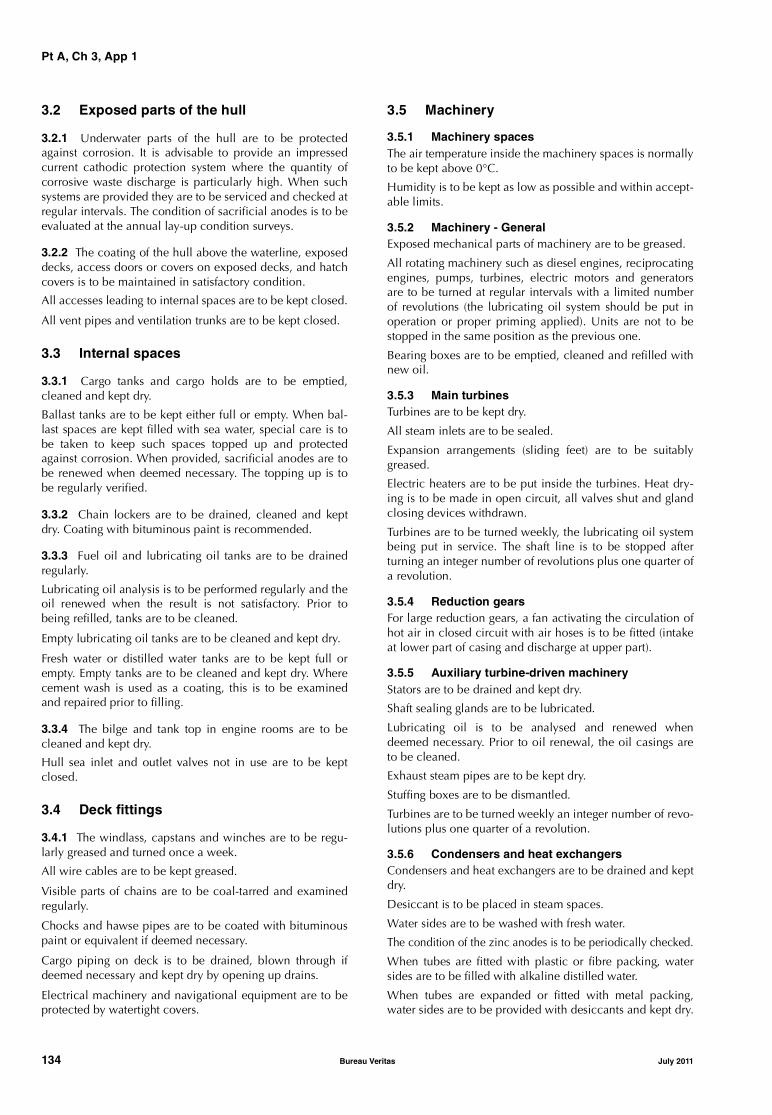
Pt A, Ch 3, App 1
3.2 Exposed parts of the hull
3.2.1 Underwater parts of the hull are to be protectedagainst corrosion. It is advisable to provide an impressedcurrent cathodic protection system where the quantity ofcorrosive waste discharge is particularly high. When suchsystems are provided they are to be serviced and checked atregular intervals. The condition of sacrificial anodes is to beevaluated at the annual lay-up condition surveys.
3.2.2 The coating of the hull above the waterline, exposeddecks, access doors or covers on exposed decks, and hatchcovers is to be maintained in satisfactory condition.
All accesses leading to internal spaces are to be kept closed.
All vent pipes and ventilation trunks are to be kept closed.
3.3 Internal spaces
3.3.1 Cargo tanks and cargo holds are to be emptied,cleaned and kept dry.
Ballast tanks are to be kept either full or empty. When bal-last spaces are kept filled with sea water, special care is tobe taken to keep such spaces topped up and protectedagainst corrosion. When provided, sacrificial anodes are tobe renewed when deemed necessary. The topping up is tobe regularly verified.
3.3.2 Chain lockers are to be drained, cleaned and keptdry. Coating with bituminous paint is recommended.
3.3.3 Fuel oil and lubricating oil tanks are to be drainedregularly.
Lubricating oil analysis is to be performed regularly and theoil renewed when the result is not satisfactory. Prior tobeing refilled, tanks are to be cleaned.
Empty lubricating oil tanks are to be cleaned and kept dry.
Fresh water or distilled water tanks are to be kept full orempty. Empty tanks are to be cleaned and kept dry. Wherecement wash is used as a coating, this is to be examinedand repaired prior to filling.
3.3.4 The bilge and tank top in engine rooms are to becleaned and kept dry.
Hull sea inlet and outlet valves not in use are to be keptclosed.
3.4 Deck fittings
3.4.1 The windlass, capstans and winches are to be regu-larly greased and turned once a week.
All wire cables are to be kept greased.
Visible parts of chains are to be coal-tarred and examinedregularly.
Chocks and hawse pipes are to be coated with bituminouspaint or equivalent if deemed necessary.
Cargo piping on deck is to be drained, blown through ifdeemed necessary and kept dry by opening up drains.
Electrical machinery and navigational equipment are to beprotected by watertight covers.
3.5 Machinery
3.5.1 Machinery spacesThe air temperature inside the machinery spaces is normallyto be kept above 0°C.
Humidity is to be kept as low as possible and within accept-able limits.
3.5.2 Machinery - GeneralExposed mechanical parts of machinery are to be greased.
All rotating machinery such as diesel engines, reciprocatingengines, pumps, turbines, electric motors and generatorsare to be turned at regular intervals with a limited numberof revolutions (the lubricating oil system should be put inoperation or proper priming applied). Units are not to bestopped in the same position as the previous one.
Bearing boxes are to be emptied, cleaned and refilled withnew oil.
3.5.3 Main turbinesTurbines are to be kept dry.
All steam inlets are to be sealed.
Expansion arrangements (sliding feet) are to be suitablygreased.
Electric heaters are to be put inside the turbines. Heat dry-ing is to be made in open circuit, all valves shut and glandclosing devices withdrawn.
Turbines are to be turned weekly, the lubricating oil systembeing put in service. The shaft line is to be stopped afterturning an integer number of revolutions plus one quarter ofa revolution.
3.5.4 Reduction gearsFor large reduction gears, a fan activating the circulation ofhot air in closed circuit with air hoses is to be fitted (intakeat lower part of casing and discharge at upper part).
3.5.5 Auxiliary turbine-driven machineryStators are to be drained and kept dry.
Shaft sealing glands are to be lubricated.
Lubricating oil is to be analysed and renewed whendeemed necessary. Prior to oil renewal, the oil casings areto be cleaned.
Exhaust steam pipes are to be kept dry.
Stuffing boxes are to be dismantled.
Turbines are to be turned weekly an integer number of revo-lutions plus one quarter of a revolution.
3.5.6 Condensers and heat exchangersCondensers and heat exchangers are to be drained and keptdry.
Desiccant is to be placed in steam spaces.
Water sides are to be washed with fresh water.
The condition of the zinc anodes is to be periodically checked.
When tubes are fitted with plastic or fibre packing, watersides are to be filled with alkaline distilled water.
When tubes are expanded or fitted with metal packing,water sides are to be provided with desiccants and kept dry.
134 Bureau Veritas July 2011

Pt A, Ch 3, App 1
3.5.7 Auxiliary machinery
Air receivers are to be drained, opened up and cleaned.Pressure relief valves are to be cleaned and slightly lubri-cated.
Air compressor crankcases are to be drained, cleaned andrefilled with clean oil. Cylinders and valves are to be lubri-cated. Coolers are to be drained and dried. Air drains are tobe opened and the system dried.
Air start lines are to be drained and dried.
Hot-wells/return tanks are to be drained and dried.
De-aerators are to be drained and dried.
Feed pumps and extraction pumps are to be drained anddried.
Air ejectors are to be drained and dried.
Main circulation pumps are to be drained and dried.
Evaporators are to be drained, cleaned and dried.
3.5.8 Piping
Pipes not in use are to be drained and kept dry.
3.5.9 Diesel engines
Daily tank fuel oil outlet pipes and all injection equipmentare to be filled with filtered gas oil.
Fresh water circuits are to be filled with water mixed withrust inhibitors. Fresh water pH is to be checked monthly.
Oil of hydraulic regulators is to be replaced.
Sea water cooling pipes are to be drained.
Crankcases are to be provided with desiccant.
Starting valves are to be lubricated (internally and exter-nally).
Motor oil is to be sprayed in cylinders and on all externalparts liable to corrosion.
Cams and cylinders are to be motor oil sprayed monthly.
Turbo-compressor/charger ball bearings are to be oilsprayed and rotated for an integer number of revolutionsplus one quarter of a revolution.
Engine air inlets and exhaust gas pipes are to be sealed.
Scavenge spaces are to be cleaned
Engines are to be turned weekly.
3.5.10 Shaft lines
Shaft lines are to be coated with grease.
Shaft bearing cooling pipes are to be drained.
For sea water lubricated propeller shafts, the packing glandof the engine room stuffing box is to be tightened.
For oil lubricated sterntubes, lubricating oil is to be ana-lysed and renewed if not satisfactory. The oil level in thetank is to be verified regularly.
Propeller shaft lines are to be rotated an integer number ofrevolutions plus one quarter of a revolution.
3.6 Electrical installations
3.6.1 Main and secondary switchboards, sub-feeder pan-els, fuse panels and starters are to be made tight. Desiccantis to be provided.
Contacts of relays, breakers and switch-breakers are to becoated with neutral vaseline.
Bearings of generators are to be cleaned of old grease andprotected with new oil or grease.
Carbon brushes are to be lifted off their commutations.
3.6.2 Electrical insulation of each item is to be kept at aminimum 200,000 Ohms and general insulation is to be notless than 50,000 Ohms. Local electric heating may be nec-essary to improve the level of insulation, particularly in thegenerators/alternators and large motors.
A insulation resistance test is to be performed regularly.
3.7 Steering gear
3.7.1 Exposed mechanical parts are to be greased or oilsprayed.
For electrical parts the same preservation measures given in[3.6] are to be taken.
It is recommended that the steering gear should be operatedmonthly.
3.8 Boilers
3.8.1 Smoke sides of boilers are to be swept, washed cleanwith basic hot water and hot air dried.
3.8.2 Water and steam sides should preferably be pre-served using the dry method, keeping the moisture at thelowest possible level, the ideal level being between 30%and 35%. It is advisable to ensure that no residual waterremains to cause rapid corrosion. Drum doors are to bekept closed.
In other cases, it is advisable to keep the boilers, superheat-ers and economisers filled with water having a pH around10,5. Hydrazine hydrate treatment of the water is preferableto reduce risks of corrosion caused by dissolved oxygen.The water is to be regularly analysed.
3.8.3 Air heaters are to be cleaned and kept dry.
Uptake, shell and fan outlets are to be cleaned and keptclosed with watertight hoods.
Burners are to be dismantled, and atomisers greased.
Desiccant is to be provided in furnaces where deemed nec-essary.
Expansion arrangements (sliding feet) are to be suitablygreased.
The internal condition of boilers is to be checked everythree months.
July 2011 Bureau Veritas 135

Pt A, Ch 3, App 1
3.8.4 Boilers may also be preserved sealed with inert gas(nitrogen), provided that cocks and valves are tight and theinstallation allows an internal pressure of at least 0,05 bar tobe maintained to prevent air penetration. Regular checks ofthe overpressure are to be carried out and results recordedin the log-book.
3.9 Automated installation
3.9.1 Recommendations for electronic components are thesame as those given for electrical installations.For pneumatic parts the manufacturers’ recommendationsare to be followed and the system is to be checked regu-larly.
Pressure, temperature or level sensors are generally notaffected by damage when not used. However, when availa-ble, the manufacturers’ recommendations are to be followed.
4 Lay-up site and mooring arrangements
4.1 General
4.1.1 The choice and suitability of the lay-up site, as wellas the type of mooring conditions, the mooring arrange-ments and their efficiency during the lay-up period remainthe responsibility of the Owner.
However, at the Owner’s request, the mooring arrangementmay be reviewed by the Society.
4.2 Recommendations for the lay-up site
4.2.1 The following recommendations are to be consideredby Owners regarding the choice and suitability of the lay-upsite.
The site should be:• sheltered from open sea, strong currents and waves• not exposed to whirling winds or turbulent tidal waves• not exposed to moving ice
• clear of corrosive waste waters• provided with adequate ship/shore communications.
4.3 Recommendations for the mooring arrangements
4.3.1 The following recommendations are to be consideredby Owners with respect to the mooring arrangements:• ground holding should be adequate• vessels laid-up to buoys or anchored should be moored
in such a way as to be prevented from swinging withnormal wind and tidal changes
• chain cables should not be subject to cross-contact ortwisting and stern anchorage should generally be pro-vided
• laid-up ships should be in ballast condition in order toreduce the effects of wind. Due consideration should begiven to the still water bending moment. For guidance,normal ballast draft should be roughly between 30%and 50% of the maximum draft.
4.3.2 Ships should normally be moored singly. However,when several ships are moored together, the following pro-visions are to be made:
• ships are to be moored bow to stern
• ships are to be of approximately the same size
• the number of ships moored together is, in principle, notto exceed six
• breast-lines are to be of similar elasticity
• fenders are to be provided.
4.4 Review of the mooring arrangements
4.4.1 As indicated in [4.1.1], at the Owners’ request, themooring arrangements may be reviewed by the Society.
4.4.2 The proposal for the mooring arrangements is in suchcase to be submitted by the Owner and is to include the fol-lowing information.
a) Mooring site:
• geographical area (to be specified on a map)
• characteristics of the sea bottom
• water depth
• preferential angular sectors (effects of wind / tide /current) indicated according to statistical studies
• wave characteristics (amplitude, periods)
b) Geometry of mooring arrangements:
• ship’s position and direction
• shore anchorage
• diagram showing mooring equipment (fore and aft)
• angle between chain cables and ship’s centreline
c) Characteristics of mooring equipment:
• maximum holding strength of each anchor
• type of mooring lines (chains, cables, sinkers, etc.)
• length of each section
• weight of each section
• mechanical characteristics of each section (breakingload)
• weight of sinkers.
4.4.3 On completion of the installation, the mooringarrangements are to be surveyed by the Society. When theship is anchored, the underwater installation is to beinspected by a diver whose report is to be presented to theSociety.
4.4.4 It is the responsibility of the Owners to ascertain theefficiency of the mooring arrangements during the lay-upperiod. The mooring arrangements are to be re-examined atregular intervals (at least each year when the ship isanchored) and when abnormal weather conditions occur atthe lay-up site.
136 Bureau Veritas July 2011

Pt A, Ch 3, App 1
5 Surveys
5.1 Laying-up survey
5.1.1 At the beginning of the lay-up period a laying-up sur-vey is to be carried out whose scope is to verify that thesafety conditions, preservation measures, lay-up site andmooring arrangements are in accordance with the programagreed by the Society.
5.1.2 Upon satisfactory completion of this survey, anendorsement to confirm that the ship has been placed inlay-up is entered on the Certificate of Classification, whichis subsequently to be kept on board.
5.2 Annual lay-up condition survey
5.2.1 As described in Ch 2, Sec 2, [8], an annual lay-upcondition survey is to be performed in lieu of the normalannual class surveys. The purpose of this survey is to ascer-tain that the lay-up maintenance program implemented iscontinuously complied with.
5.2.2 It is to be checked that the arrangements made for thelay-up are unchanged and that the maintenance work andtests are carried out in accordance with the maintenancemanual and recorded in the lay-up log-book.
5.2.3 Upon satisfactory completion of the survey, the Cer-tificate of Classification is endorsed.
5.3 Re-commissioning survey
5.3.1 Owners are to make the necessary arrangements toremove the temporary lay-up installations provided for pres-ervation measures and the protective materials and coatings(oil, grease, inhibitors, desiccants), before the survey iscommenced.
It is the Owners’ responsibility to verify that the ship partsthat are not covered by class are reactivated in satisfactoryoperational condition.
5.3.2 The scope of the re-commissioning survey is toinclude:
• a general examination of the hull, deck fittings, safetysystems, machinery installations (including boilerswhose survey is not due) and steering gear
• all periodical surveys due at the date of re-commission-ing or which became overdue during the lay-up period
• dealing with the recommendations due at the date of re-commissioning or which became due during the lay-upperiod.
5.3.3 For the hull the following is to be carried out:
• examination of shell plating above the waterline, deckplating, hatch covers and coamings
• examination of load line items
• overall survey of all cargo tanks/holds
• overall survey of representative ballast tanks when thelay-up period does not exceed two years
• overall survey of all ballast tanks when the lay-up periodis two years and over
• function tests of bilge and ballast systems.
5.3.4 For the deck fittings the following is to be carried out:
• examination of the fire main under working pressure
• where possible, examination of deck piping underworking pressure
• function tests of class items
• checking inert gas installation under working conditionafter inspection of water seal and function test of decknon-return valve and pressure/vacuum valves.
5.3.5 For machinery installations the following is to bechecked:
• the analysis of lubricating oil of main engines, auxiliaryengines, reduction gears, main thrust bearings andsterntube
• the general condition of crankcase, crankshaft, pistonrods and connecting rods of diesel engines
• the crankshaft deflections of diesel engines. In additionwhen engines have been laid-up for more than twoyears, one piston is to be disconnected and one liner isto be removed for examination. Dismantling is to beextended if deemed necessary
• the condition of blades of turbines through the inspec-tion doors
• the condition of the water side of condensers and heatexchangers
• the condition of expansion arrangements
• the condition of reduction gears through the inspectiondoors
• the condition after overhauling of pressure relief devices
• the test of bilge level alarms, when fitted.
5.3.6 The main and emergency electrical installations areto be tested. The parallel shedding of main generators andmain switchboard safety devices are to be checked. Aninsulation resistance test of the electrical installation is to beperformed.
5.3.7 For the fire prevention, detection and fire-fighting sys-tems, the following is to be examined and/or tested:
• remote control for quick closing of fuel oil valves, stop-ping of fuel oil pumps and ventilation systems, closingof fire doors and watertight doors
• fire detectors and alarms
• fire-fighting equipment.
July 2011 Bureau Veritas 137

Pt A, Ch 3, App 1
5.3.8 The automated installation is to be checked forproper operation.
5.3.9 When classed, the installations for refrigerated cargoare to be examined under working conditions. Where thelay-up period exceeds two years, representative compo-nents of the installation are to be dismantled.
5.3.10 For cargo installations on liquefied gas carriers, thefollowing is to be carried out:
• inspection of the primary barrier in tanks
• for membrane tanks, a global gas test of tanks whoseresults are to be compared with those obtained at ship’sdelivery
• testing of gas piping at working pressure using inert gas.
A Surveyor of the Society is to attend the first cooling downand loading of the ship.
5.3.11 For other specific classed installations, the Ownersare to submit a survey program to the Society.
5.3.12 On completion of the above surveys, sea trials are tobe performed in the presence of a Surveyor of the Society.The sea trials are to include:• verification of the satisfactory performance of the deck
installations, main propulsion system and essential aux-iliaries, including a test of the safety devices
• an anchoring test• complete tests of steering gear• full head and full astern tests• tests of automated machinery systems, where applica-
ble.
5.3.13 Upon satisfactory completion of the surveys, anendorsement to confirm the carrying out of all relevant sur-veys and the re-commissioning of the ship is entered on theCertificate of Classification.
138 Bureau Veritas July 2011

Part AClassification and Surveys
Chapter 4
SCOPE OF SURVEYS IN RESPECT OFTHE DIFFERENT SERVICES OF SHIPS
SECTION 1 GENERAL
SECTION 2 SINGLE SKIN AND DOUBLE SKIN BULK CARRIERS
SECTION 3 OIL TANKERS AND COMBINATION CARRIERS
SECTION 4 CHEMICAL TANKERS
SECTION 5 LIQUEFIED GAS CARRIERS
SECTION 6 RO-RO CARGO SHIPS, PASSENGER SHIPS, RO-RO PASSENGER SHIPS
SECTION 7 GENERAL CARGO SHIPS
SECTION 8 OTHER SERVICE NOTATIONS
APPENDIX 1 OIL TANKER LONGITUDINAL STRENGTH ASSESSMENT
July 2011 Bureau Veritas 139

140 Bureau Veritas July 2011

Pt A, Ch 4, Sec 1
SECTION 1 GENERAL
1 General
1.1
1.1.1 The purpose of this Chapter is to give details on thescope of surveys of certain ships which, due to the servicenotation assigned and related equipment, need specificrequirements to be verified for the maintenance of theirclass.
1.1.2 These specific requirements either are additional toor supersede those stipulated in Part A, Chapter 3, whichgives general requirements for surveys applicable to alltypes of ships: this is indicated in each Section of this Chap-ter. These surveys are to be carried out at intervals asdescribed in Ch 2, Sec 2, concurrently with the surveys ofthe same type, i.e. annual, intermediate or class renewalsurveys, detailed in Part A, Chapter 3.
1.1.3 Owners are reminded that a general examination ofthe ship having the same scope of an annual survey is to becarried out at the completion of the class renewal survey,
see Ch 3, Sec 3, [1.1.7]. Where specific requirements aregiven in this Chapter for the class renewal survey, they areadditional to the applicable requirements for the annualsurvey.
2 Service notations subject to additional surveys
2.1
2.1.1 The specific requirements detailed in this Chapter arelinked to the service notation(s) assigned to the ship at therequest of the Owner. Where a ship has more than oneservice notation, the specific requirements linked to eachone are applicable, insofar as they are not contradictory (insuch case, the most stringent requirement will be applied).
2.1.2 Tab 1 indicates which service notations are subject tospecific requirements, and in which Section or Article theyare specified.
Table 1 : Service notations for which specific requirements are applicable
Service notation assignedSection or Article applicable
in this ChapterType of surveys affected by these specific requirements
Remarks
bulk carrier ESPbulk carrier BC-A ESPbulk carrier BC-B ESPbulk carrier BC-C ESPore carrier ESPcombination carrier/OBO ESPcombination carrier/OOC ESP
Ch 4, Sec 2 annual surveyintermediate surveyclass renewal survey
subject to enhanced survey program
oil tanker ESPcombination carrier/OBO ESPcombination carrier/OOC ESP
Ch 4, Sec 3 annual surveyintermediate surveyclass renewal survey
subject to enhanced survey program
chemical tanker ESP Ch 4, Sec 4 annual surveyintermediate surveyclass renewal survey
subject to enhanced survey program
liquefied gas carrier Ch 4, Sec 5 annual surveyintermediate surveyclass renewal survey
ro-ro cargo shippassenger shipro-ro passenger ship
Ch 4, Sec 6 annual surveyclass renewal survey
survey of shell and inner doors is included
general cargo ship Ch 4, Sec 7 annual surveyintermediate surveyclass renewal survey
container ship or ship equipped for carriage of containers
Ch 4, Sec 8, [2] annual surveyclass renewal survey
July 2011 Bureau Veritas 141
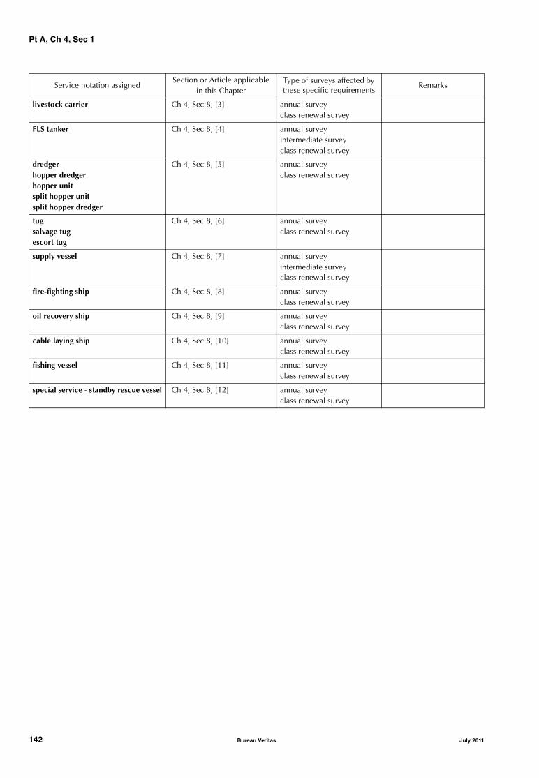
Pt A, Ch 4, Sec 1
livestock carrier Ch 4, Sec 8, [3] annual surveyclass renewal survey
FLS tanker Ch 4, Sec 8, [4] annual surveyintermediate surveyclass renewal survey
dredgerhopper dredgerhopper unitsplit hopper unitsplit hopper dredger
Ch 4, Sec 8, [5] annual surveyclass renewal survey
tugsalvage tugescort tug
Ch 4, Sec 8, [6] annual surveyclass renewal survey
supply vessel Ch 4, Sec 8, [7] annual surveyintermediate surveyclass renewal survey
fire-fighting ship Ch 4, Sec 8, [8] annual surveyclass renewal survey
oil recovery ship Ch 4, Sec 8, [9] annual surveyclass renewal survey
cable laying ship Ch 4, Sec 8, [10] annual surveyclass renewal survey
fishing vessel Ch 4, Sec 8, [11] annual surveyclass renewal survey
special service - standby rescue vessel Ch 4, Sec 8, [12] annual surveyclass renewal survey
Service notation assignedSection or Article applicable
in this ChapterType of surveys affected by these specific requirements
Remarks
142 Bureau Veritas July 2011

Pt A, Ch 4, Sec 2
SECTION 2 SINGLE SKIN AND DOUBLE SKIN BULK CARRIERS
1 General
1.1 Application
1.1.1 The requirements of this Section apply to all self-pro-pelled ships which have been assigned one of the followingservice notations:
• bulk carrier ESP (whether of single or double skin con-struction)
• bulk carrier BC-A ESP (whether of single or double skinconstruction)
• bulk carrier BC-B ESP (whether of single or double skinconstruction)
• bulk carrier BC-C ESP (whether of single or double skinconstruction)
• ore carrier ESP
• combination carrier/OBO ESP
• combination carrier/OOC ESP.
Note 1: A double skin bulk carrier is a ship which is constructedgenerally with single deck, topside tanks and hopper side tanks incargo spaces, and is intended primarily to carry dry cargo in bulk,including such types as ore carriers and combination carriers, inwhich all cargo holds are bounded by a double-side skin (regard-less of the width of the wing space).
Note 2: For bulk carriers with hybrid cargo hold arrangements, e.g.with some cargo holds of single side skin and others of double sideskin, the requirements of single side skin bulk carriers are to applyto cargo holds of single side skin and the requirements of doubleskin bulk carriers are to apply to cargo holds of double side skinand associated wing spaces.
Note 3: For combination carriers, additional requirements are spec-ified in Ch 4, Sec 3, as applicable.
1.1.2 The requirements apply to the surveys of the hullstructure and piping systems in way of cargo holds, coffer-dams, pipe tunnels, void spaces, fuel oil tanks within thecargo length area and all ballast tanks. They are additionalto the requirements applicable to the remainder of the ship,given in Part A, Chapter 3 according to the relevant surveys.
1.1.3 The requirements contain the minimum extent ofexamination, thickness measurements and tank testing.When substantial corrosion, as defined in Ch 2, Sec 2,[2.2.7], and/or structural defects are found, the survey is tobe extended and is to include additional close-up surveyswhen necessary.
1.1.4 Thickness measurements of structures in areas whereclose-up surveys are required, shall be carried out simulta-neously with close-up surveys.
1.1.5 In all cases the extent of thickness measurements is tobe sufficient as to represent the actual average condition.
1.1.6 When, in any survey, thickness measurements arerequired:
• the procedure detailed in Ch 2, Sec 2, [2.3] is to beapplied
• the thickness measurement operator is to attend the sur-vey planning meeting held prior to commencing thesurvey.
1.1.7 Special consideration may be given to the extent ofclose-up surveys and/or thickness measurements in cargoholds as required below for class renewal, intermediate orannual surveys, when all internal and external surfaces ofhatch coamings and hatch covers, and all internal surfacesof the cargo holds, excluding the flat tank top areas and thehopper tank sloped plating approximately 300 mm belowthe side shell frame end brackets, have protective coating ingood condition.
The above special consideration may also be given to exist-ing bulk carriers, where Owners elect to coat or recoatcargo holds, in accordance with the Manufacturers’ recom-mendations. However, prior to re-coating the cargo holds,scantlings are to be assessed in the presence of a Surveyorof the Society.
Note 1: Special consideration (or specially considered) as used inthis Section is intended to mean as a minimum, that sufficientclose-up inspection and thickness measurements are taken to con-firm the actual average condition of the structure under the coating.
1.1.8 Ships which are required to comply with Ch 6, Sec 2,[1.3] are subject to the additional thickness measurementscontained in Ch 6, Sec 2, [1.3.4] and Ch 6, Sec 2, [1.3.5]with respect to the vertically corrugated transverse water-tight bulkhead between cargo holds Nos. 1 and 2 for pur-poses of determining compliance with Ch 6, Sec 2, [1.3]prior to the relevant compliance deadline stipulated in Ch6, Sec 2, [1.2.1] and at subsequent intermediate surveys (forships over 10 years of age) and class renewal surveys forpurposes of verifying continuing compliance with Ch 6, Sec2, [1.3].
1.1.9 Ships which are required to comply with Ch 6, Sec 2,[5] are subject to the additional thickness measurementscontained in Ch 6, Sec 2, [5.3] with respect to the side shellframes and brackets for the purposes of determining compli-ance with Ch 6, Sec 2, [5] prior to the relevant compliancedeadline stipulated in Ch 6, Sec 2, [5.2] and at subsequentintermediate and class renewal surveys for purposes of veri-fying continuing compliance with Ch 6, Sec 2, [5].
July 2011 Bureau Veritas 143
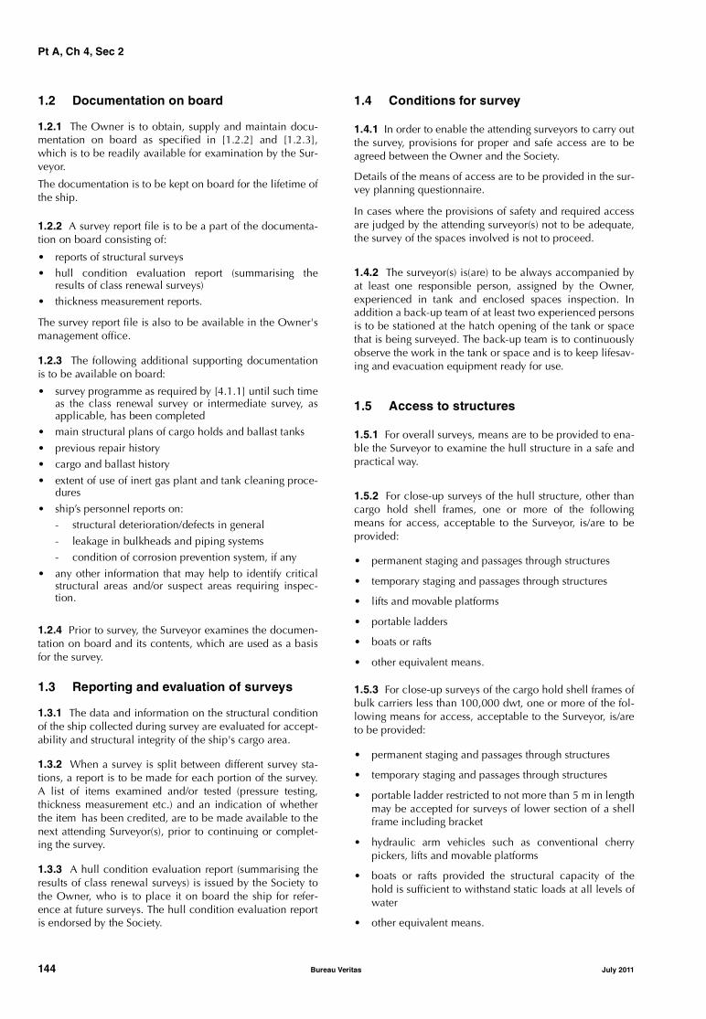
Pt A, Ch 4, Sec 2
1.2 Documentation on board
1.2.1 The Owner is to obtain, supply and maintain docu-mentation on board as specified in [1.2.2] and [1.2.3],which is to be readily available for examination by the Sur-veyor.
The documentation is to be kept on board for the lifetime ofthe ship.
1.2.2 A survey report file is to be a part of the documenta-tion on board consisting of:
• reports of structural surveys• hull condition evaluation report (summarising the
results of class renewal surveys)• thickness measurement reports.
The survey report file is also to be available in the Owner'smanagement office.
1.2.3 The following additional supporting documentationis to be available on board:
• survey programme as required by [4.1.1] until such timeas the class renewal survey or intermediate survey, asapplicable, has been completed
• main structural plans of cargo holds and ballast tanks
• previous repair history• cargo and ballast history
• extent of use of inert gas plant and tank cleaning proce-dures
• ship’s personnel reports on: - structural deterioration/defects in general
- leakage in bulkheads and piping systems- condition of corrosion prevention system, if any
• any other information that may help to identify criticalstructural areas and/or suspect areas requiring inspec-tion.
1.2.4 Prior to survey, the Surveyor examines the documen-tation on board and its contents, which are used as a basisfor the survey.
1.3 Reporting and evaluation of surveys
1.3.1 The data and information on the structural conditionof the ship collected during survey are evaluated for accept-ability and structural integrity of the ship's cargo area.
1.3.2 When a survey is split between different survey sta-tions, a report is to be made for each portion of the survey.A list of items examined and/or tested (pressure testing,thickness measurement etc.) and an indication of whetherthe item has been credited, are to be made available to thenext attending Surveyor(s), prior to continuing or complet-ing the survey.
1.3.3 A hull condition evaluation report (summarising theresults of class renewal surveys) is issued by the Society tothe Owner, who is to place it on board the ship for refer-ence at future surveys. The hull condition evaluation reportis endorsed by the Society.
1.4 Conditions for survey
1.4.1 In order to enable the attending surveyors to carry outthe survey, provisions for proper and safe access are to beagreed between the Owner and the Society.
Details of the means of access are to be provided in the sur-vey planning questionnaire.
In cases where the provisions of safety and required accessare judged by the attending surveyor(s) not to be adequate,the survey of the spaces involved is not to proceed.
1.4.2 The surveyor(s) is(are) to be always accompanied byat least one responsible person, assigned by the Owner,experienced in tank and enclosed spaces inspection. Inaddition a back-up team of at least two experienced personsis to be stationed at the hatch opening of the tank or spacethat is being surveyed. The back-up team is to continuouslyobserve the work in the tank or space and is to keep lifesav-ing and evacuation equipment ready for use.
1.5 Access to structures
1.5.1 For overall surveys, means are to be provided to ena-ble the Surveyor to examine the hull structure in a safe andpractical way.
1.5.2 For close-up surveys of the hull structure, other thancargo hold shell frames, one or more of the followingmeans for access, acceptable to the Surveyor, is/are to beprovided:
• permanent staging and passages through structures
• temporary staging and passages through structures
• lifts and movable platforms
• portable ladders
• boats or rafts
• other equivalent means.
1.5.3 For close-up surveys of the cargo hold shell frames ofbulk carriers less than 100,000 dwt, one or more of the fol-lowing means for access, acceptable to the Surveyor, is/areto be provided:
• permanent staging and passages through structures
• temporary staging and passages through structures
• portable ladder restricted to not more than 5 m in lengthmay be accepted for surveys of lower section of a shellframe including bracket
• hydraulic arm vehicles such as conventional cherrypickers, lifts and movable platforms
• boats or rafts provided the structural capacity of thehold is sufficient to withstand static loads at all levels ofwater
• other equivalent means.
144 Bureau Veritas July 2011

Pt A, Ch 4, Sec 2
1.5.4 For close-up surveys of the cargo hold shell frames ofbulk carriers 100,000 dwt and above, the use of portable lad-ders is not accepted, and one or more of the following meansfor access, acceptable to the Surveyor, is/are to be provided:
a) Annual surveys, intermediate surveys for ships less thanten years of age and class renewal surveys for ships fiveyears of age or less:
• permanent staging and passages through structures
• temporary staging and passages through structures
• hydraulic arm vehicles such as conventional cherrypickers, lifts and movable platforms
• boats or rafts provided the structural capacity of thehold is sufficient to withstand static loads at all lev-els of water
• other equivalent means.
b) Subsequent intermediate surveys and class renewal sur-veys:
• either permanent or temporary staging and passagesthrough structures for close-up survey of at least theupper part of hold frames
• hydraulic arm vehicles such as conventional cherrypickers for surveys of lower and middle part of shellframes as alternative to staging
• lifts and movable platforms
• boats or rafts provided the structural capacity of thehold is sufficient to withstand static loads at all lev-els of water
• other equivalent means.
Notwithstanding the above requirements, the use of a porta-ble ladder fitted with a mechanical device to secure theupper end of the ladder is acceptable for the:
• close-up survey of sufficient extent, minimum 25% offrames, to establish the condition of the lower region ofthe shell frames including approximately the lower onethird length of side frame at side shell and side frameend attachment and the adjacent shell plating in the for-ward cargo hold at annual survey of cargo holds for sin-gle skin bulk carriers between 10 and 15 years
• close-up survey of sufficient extent, minimum 25% offrames, to establish the condition of the lower region ofthe shell frames including approximately the lower onethird length of side frame at side shell and side frameend attachment and the adjacent shell plating in the for-ward cargo hold and one other selected cargo hold atannual survey of cargo holds for single skin bulk carriersover 15 years.
2 Annual survey
2.1 Hatch covers and coamings, weather decks
2.1.1 Confirmation is to be obtained that no unapprovedchanges have been made to the hatch covers, hatch coamingsand their securing and sealing devices since the last survey.
2.1.2 A thorough survey of cargo hatch covers and coam-ings is only possible by examination in the open as well asclosed positions and is to include verification of properopening and closing operation. As a result, the hatch coversets within the forward 25% of the ship's length and at leastone additional set, such that all sets on the ship are assessedat least once in every five year period, are to be surveyedopen, closed and in operation to the full extent on eachdirection, including:
a) stowage and securing in open condition
b) proper fit and efficiency of sealing in closed condition,and
c) operational testing of hydraulic and power components,wires, chains, and link drives.
The closing of the covers is to include the fastening of allperipheral, and cross joint cleats or other securing devices.Particular attention is to be paid to the condition of thehatch covers in the forward 25% of the ship's length, wheresea loads are normally greatest.
2.1.3 If there are indications of difficulty in operating andsecuring hatch covers, additional sets above those requiredby [2.1.2], at the discretion of the Surveyor, are to be testedin operation.
2.1.4 Where the cargo hatch securing system does notfunction properly, repairs are to be carried out under thesupervision of the Society.
2.1.5 For each cargo hatch cover set, the following itemsare to be surveyed:
a) cover panels, including side plates, and stiffener attach-ments that may be accessible in the open position byclose-up survey (for corrosion, cracks, deformation)
b) sealing arrangements of perimeter and cross joints (gas-kets for condition and permanent deformation, flexibleseals on combination carriers, gasket lips, compressionbars, drainage channels and non return valves)
c) clamping devices, retaining bars, cleating (for wastage,adjustment, and condition of rubber components)
d) closed cover locating devices (for distortion and attach-ment)
e) chain or rope pulleys
f) guides
g) guide rails and track wheels
h) stoppers
i) wires, chains, tensioners, and gypsies
j) hydraulic system, electrical safety devices and inter-locks, and
k) end and interpanel hinges, pins and stools where fitted.
2.1.6 At each hatchway, the coamings, with panel stiffenersand brackets, are to be checked for corrosion, cracks anddeformation, especially of the coaming tops, includingclose-up survey.
July 2011 Bureau Veritas 145
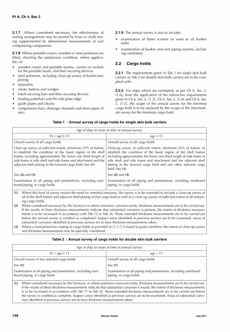
Pt A, Ch 4, Sec 2
2.1.7 Where considered necessary, the effectiveness ofsealing arrangements may be proved by hose or chalk test-ing supplemented by dimensional measurements of sealcompressing components.
2.1.8 Where portable covers, wooden or steel pontoons arefitted, checking the satisfactory condition, where applica-ble, of:• wooden covers and portable beams, carriers or sockets
for the portable beam, and their securing devices• steel pontoons, including close-up survey of hatchcover
plating• tarpaulins• cleats, battens and wedges• hatch securing bars and their securing devices• loading pads/bars and the side plate edge• guide plates and chocks• compression bars, drainage channels and drain pipes (if
any).
2.1.9 The annual survey is also to include:
• examination of flame screens on vents to all bunkertanks
• examination of bunker and vent piping systems, includ-ing ventilators.
2.2 Cargo holds
2.2.1 The requirements given in Tab 1 for single skin bulkcarriers or Tab 2 for double skin bulk carriers are to be com-plied with.
2.2.2 For ships which are exempted, as per Ch 6, Sec 2,[1.6], from the application of the retroactive requirementsgiven in Ch 6, Sec 2, [1.3], Ch 6, Sec 2, [1.4] and Ch 6, Sec2, [1.5], the scope of the annual survey for the foremostcargo hold is to be replaced by the scope of the intermedi-ate survey for the foremost cargo hold.
Table 1 : Annual survey of cargo holds for single skin bulk carriers
Table 2 : Annual survey of cargo holds for double skin bulk carriers
Age of ship (in years at time of annual survey)
10 < age ≤ 15 age > 15
Overall survey of all cargo holds Overall survey of all cargo holds
Close-up survey of sufficient extent, minimum 25% of frames,to establish the condition of the lower region of the shellframes including approximately the lower one third length ofside frame at side shell and side frame end attachment and theadjacent shell plating in the forward cargo hold. See (1)
Close-up survey of sufficient extent, minimum 25% of frames, toestablish the condition of the lower region of the shell framesincluding approximately the lower one third length of side frame atside shell and side frame end attachment and the adjacent shellplating in the forward cargo hold and one other selected cargohold. See (1)
See (2) and (3) See (2) and (3)
Examination of all piping and penetrations, including over-board piping, in cargo holds
Examination of all piping and penetrations, including overboardpiping, in cargo holds
(1) Where this level of survey reveals the need for remedial measures, the survey is to be extended to include a close-up survey ofall of the shell frames and adjacent shell plating of that cargo hold as well as a close-up survey of sufficient extent of all remain-ing cargo holds.
(2) When considered necessary by the Surveyor or where extensive corrosion exists, thickness measurements are to be carried out.If the results of these thickness measurements indicate that substantial corrosion is present, the extent of thickness measure-ments is to be increased in accordance with Tab 12 to Tab 16. These extended thickness measurements are to be carried outbefore the annual survey is credited as completed. Suspect areas identified at previous surveys are to be examined. Areas ofsubstantial corrosion identified at previous surveys are to have thickness measurements taken.
(3) Where a hard protective coating in cargo holds as provided in [1.1.7] is found in good condition, the extent of close-up surveyand thickness measurements may be specially considered.
Age of ship (in years at time of annual survey)
10 < age ≤ 15 age > 15
Overall survey of two selected cargo holds Overall survey of all cargo holds
See (1) See (1)
Examination of all piping and penetrations, including over-board piping, in cargo holds
Examination of all piping and penetrations, including overboard piping, in cargo holds
(1) When considered necessary by the Surveyor, or where extensive corrosion exists, thickness measurements are to be carried out.If the results of these thickness measurements indicate that substantial corrosion is found, the extent of thickness measurementsis to be increased in accordance with Tab 17 to Tab 20. These extended thickness measurements are to be carried out beforethe survey is credited as complete. Suspect areas identified at previous surveys are to be examined. Areas of substantial corro-sion identified at previous surveys are to have thickness measurements taken.
146 Bureau Veritas July 2011

Pt A, Ch 4, Sec 2
2.3 Ballast tanks
2.3.1 Ballast tanks are to be internally examined whenrequired as a consequence of the results of the classrenewal survey or the intermediate survey; see [4.3.6] andfootnote (3) of Tab 4 for single skin bulk carriers or footnote(3) of Tab 6 for double skin bulk carriers.
2.3.2 When considered necessary by the Surveyor orwhere extensive corrosion exists, thickness measurementsare to be carried out. If the results of these thickness meas-urements indicate that substantial corrosion is found, theextent of thickness measurements is to be increased inaccordance with Tab 12 to Tab 16 for single skin bulk carri-ers or Tab 17 to Tab 20 for double skin bulk carriers. Theseextended thickness measurements are to be carried outbefore the survey is credited as completed.
Suspect areas identified at previous surveys are to be exam-ined.
Areas of substantial corrosion identified at previous surveysare to have thickness measurements taken.
3 Intermediate survey
3.1 Ships 10 years of age or less
3.1.1 The requirements for survey of cargo holds given inTab 3 for single skin bulk carriers or Tab 5 for double skinbulk carriers are to be complied with.
3.1.2 The requirements for survey of salt water ballast tanksgiven in Tab 4 for single skin bulk carriers or Tab 6 for dou-ble skin bulk carriers are to be complied with.
3.2 Ships between 10 and 15 years of age
3.2.1 The scope of intermediate survey of ships between 10and 15 years of age is the scope of the preceding classrenewal survey of hull, as detailed in [4] with bottom surveyin dry condition or bottom in water survey as applicable.However, internal examination of fuel oil tanks and pres-sure testing of all tanks are not required unless deemed nec-essary by the attending Surveyor.
3.3 Ships over 15 years of age
3.3.1 The scope of intermediate survey of ships over 15years of age is the scope of the preceding class renewal sur-vey of hull, as detailed in [4] with bottom survey in dry con-dition. However, internal examination of fuel oil tanks andpressure testing of all tanks are not required unless deemednecessary by the attending Surveyor.
The overall and close-up surveys and thickness measure-ments, as applicable, of the lower portions of the cargoholds and water ballast tanks are to be carried out duringthe bottom survey in accordance with the applicablerequirements for intermediate surveys, if not already per-formed.
Lower portions of the cargo holds and ballast tanks are con-sidered to be the parts below light ballast water line.
Table 3 : Intermediate survey of cargo holds for single skin bulk carriers Ships 10 years of age or less at time of the intermediate survey
Overall survey of all cargo holds. See (1)
Close-up survey in the forward cargo hold and one other selected cargo hold, to establish the condition of:• at least 25% of the side shell frames including their upper and lower end attachments, and adjacent shell plating• the transverse bulkheadsExamination of suspect areas identified at previous surveys
See (1)
Thickness measurements to an extent sufficient to determine both general and local corrosion levels in areas subject to close-up sur-vey. The minimum requirements for thickness measurements are areas found to be suspect areas at the previous surveys. See (2), (3)and (4)
(1) Where considered necessary by the Surveyor as a result of the overall and close-up surveys, the survey is to be extended toinclude a close-up survey of all the shell frames and adjacent shell plating of that cargo hold as well as a close-up survey of suf-ficient extent of all remaining cargo holds.
(2) Where the hard protective coating in cargo holds as provided in [1.1.7] is found to be in good condition, the extent of close-upsurvey and thickness measurements may be specially considered.
(3) The extent of thickness measurements may be specially considered provided the Surveyor is satisfied by the close-up survey,that there is no structural diminution and the hard protective coatings are found to be in a good condition.
(4) Where substantial corrosion is found, the extent of thickness measurements is to be increased in accordance with the require-ments of Tab 12 to Tab 16. These extended thickness measurements are to be carried out before the survey is credited as com-pleted. Suspect areas identified at previous surveys are to be examined. Areas of substantial corrosion identified at previoussurveys are to have thickness measurements taken.
Note 1: For existing bulk carriers, where Owners may elect to coat or recoat cargo holds as noted above, consideration may begiven to the extent of the close-up and thickness measurement surveys. Prior to the coating of cargo holds of existing ships, scantlingsare to be ascertained in the presence of a Surveyor.
July 2011 Bureau Veritas 147

Pt A, Ch 4, Sec 2
Table 4 : Intermediate survey of salt water ballast spaces for single skin bulk carriers Ships 10 years of age or less at time of the intermediate survey
Table 5 : Intermediate survey of cargo holds for double skin bulk carriersShips 10 years of age or less at time of the intermediate survey
4 Class renewal survey
4.1 Survey programme and preparation for survey
4.1.1 The Owner in cooperation with the Society is to workout a specific Survey Programme prior to the commence-ment of any part of:
• the class renewal survey
• the intermediate survey for bulk carriers over 10 years ofage.
The survey programme is to be in a written format. The sur-vey is not to commence until the Survey Programme hasbeen agreed.
Prior to the development of the Survey Programme, the sur-vey planning questionnaire is to be completed by theOwner and forwarded to the Society.
The survey programme at intermediate survey may consistof the survey programme at the previous class renewal sur-vey supplemented by the hull condition evaluation report ofthat class renewal survey and later relevant survey reports.
The survey programme is to be worked out taking intoaccount any amendments to the survey requirements afterthe last class renewal survey carried out.
Overall survey of representative water ballast spaces selected by the Surveyor. The selection is to include fore and aft peak tanks anda number of other tanks, taking into account the total number and type of ballast tanks. See (1), (2) and (3)
Overall and close-up survey of suspect areas identified at previous surveys
The minimum requirements for thickness measurements are areas found to be suspect areas at previous surveys. See (4) and (5)
(1) If such overall survey reveals no visible structural defects, the examination may be limited to verification that the corrosion pre-vention system remains efficient.
(2) Where poor coating condition, corrosion or other defects are found in water ballast tanks or where a hard protective coatingwas not applied from the time of construction, the examination is to be extended to other ballast tanks of the same type.
(3) For ballast tanks other than double bottom tanks, where a hard protective coating is found in poor condition, and it is notrenewed, or where soft or semi-hard coating has been applied or where a hard protective coating was not applied from the timeof construction, the tanks in question are to be internally examined and thickness measurement carried out as considered nec-essary at annual surveys.When such breakdown of hard protective coating is found in ballast double bottom tanks or where a soft or semi-hard coatinghas been applied or where a hard protective coating has not been applied, the tanks in question may be internally examined atannual surveys. When considered necessary by the Surveyor, or where extensive corrosion exists, thickness measurements areto be carried out.
(4) The extent of thickness measurements may be specially considered provided the Surveyor is satisfied by the close-up survey,that there is no structural diminution and the hard protective coatings are found to be in a good condition.
(5) Where substantial corrosion is found, the extent of thickness measurements is to be increased in accordance with the require-ments of Tab 12 to Tab 16. These extended thickness measurements are to be carried out before the survey is credited as com-pleted. Suspect areas identified at previous surveys are to be examined. Areas of substantial corrosion identified at previoussurveys are to have thickness measurements taken.
Overall survey of all cargo holds. See (1)
Thickness measurements to an extent sufficient to determine both general and local corrosion levels at areas subject to close-up sur-vey. See (2), (3) and (4)
(1) Where considered necessary by the Surveyor as a result of the overall survey, the survey is to be extended to include a close-upsurvey of those areas of structure in the cargo holds selected by the Surveyor.
(2) The extent of thickness measurements may be specially considered provided the Surveyor is satisfied by the close-up survey thatthere is no structural diminution and the hard protective coatings are found to be in a good condition.
(3) Where substantial corrosion is found, the extent of thickness measurements is to be increased in accordance with Tab 17 to Tab20. These extended thickness measurements are to be carried out before the survey is credited as completed. Suspect areasidentified at previous surveys are to be examined. Areas of substantial corrosion identified at previous surveys are to have thick-ness measurements taken.
(4) Where a hard protective coating in cargo holds as provided in [1.1.7] is found in good condition, the extent of close-up surveyand thickness measurements may be specially considered.
Note 1: For existing bulk carriers, where Owners may elect to coat or recoat cargo holds as noted above, consideration may begiven to the extent of the close-up and thickness measurement surveys. Prior to the coating of cargo holds of existing ships, scantlingsare to be ascertained in the presence of a Surveyor.
148 Bureau Veritas July 2011
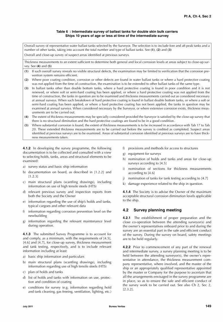
Pt A, Ch 4, Sec 2
Table 6 : Intermediate survey of ballast tanks for double skin bulk carriersShips 10 years of age or less at time of the intermediate survey
4.1.2 In developing the survey programme, the followingdocumentation is to be collected and consulted with a viewto selecting holds, tanks, areas and structural elements to beexamined:
a) survey status and basic ship information
b) documentation on board, as described in [1.2.2] and[1.2.3]
c) main structural plans (scantling drawings), includinginformation on use of high tensile steels (HTS)
d) relevant previous survey and inspection reports fromboth the Society and the Owner
e) information regarding the use of ship’s holds and tanks,typical cargoes and other relevant data
f) information regarding corrosion prevention level on thenewbuilding
g) information regarding the relevant maintenance levelduring operation.
4.1.3 The submitted Survey Programme is to account forand comply, as a minimum, with the requirements of [4.5],[4.6] and [4.7], for close-up survey, thickness measurementand tank testing, respectively, and is to include relevantinformation including at least:
a) basic ship information and particulars
b) main structural plans (scantling drawings), includinginformation regarding use of high tensile steels (HTS)
c) plan of holds and tanks
d) list of holds and tanks with information on use, protec-tion and condition of coating
e) conditions for survey (e.g. information regarding holdand tank cleaning, gas freeing, ventilation, lighting, etc.)
f) provisions and methods for access to structures
g) equipment for surveys
h) nomination of holds and tanks and areas for close-upsurveys according to [4.5]
i) nomination of sections for thickness measurementsaccording to [4.6]
j) nomination of tanks for tank testing according to [4.7]
k) damage experience related to the ship in question.
4.1.4 The Society is to advise the Owner of the maximumacceptable structural corrosion diminution levels applicableto the ship.
4.2 Survey planning meeting
4.2.1 The establishment of proper preparation and theclose co-operation between the attending surveyor(s) andthe owner's representatives onboard prior to and during thesurvey are an essential part in the safe and efficient conductof the survey. During the survey on board, safety meetingsare to be held regularly.
4.2.2 Prior to commencement of any part of the renewaland intermediate survey, a survey planning meeting is to beheld between the attending surveyor(s), the owner's repre-sentative in attendance, the thickness measurement com-pany representative, where involved, and the master of theship or an appropriately qualified representative appointedby the master or Company for the purpose to ascertain thatall the arrangements envisaged in the survey programme arein place, so as to ensure the safe and efficient conduct ofthe survey work to be carried out. See also Ch 2, Sec 2,[2.3.2].
Overall survey of representative water ballast tanks selected by the Surveyor. The selection is to include fore and aft peak tanks and anumber of other tanks, taking into account the total number and type of ballast tanks. See (1), (2) and (3)
Overall and close-up survey of suspect areas identified at previous surveys.
Thickness measurements to an extent sufficient to determine both general and local corrosion levels at areas subject to close-up sur-vey. See (4) and (5)
(1) If such overall survey reveals no visible structural defects, the examination may be limited to verification that the corrosion pre-vention system remains efficient.
(2) Where poor coating condition, corrosion or other defects are found in water ballast tanks or where a hard protective coatingwas not applied from the time of construction, the examination is to be extended to other ballast tanks of the same type.
(3) In ballast tanks other than double bottom tanks, where a hard protective coating is found in poor condition and it is notrenewed, or where soft or semi-hard coating has been applied, or where a hard protective coating was not applied from thetime of construction, the tanks in question are to be examined and thickness measurements carried out as considered necessaryat annual surveys. When such breakdown of hard protective coating is found in ballast double bottom tanks, or where a soft orsemi-hard coating has been applied, or where a hard protective coating has not been applied, the tanks in question may beexamined at annual surveys. When considered necessary by the Surveyor, or where extensive corrosion exists, thickness meas-urements are to be carried out.
(4) The extent of thickness measurements may be specially considered provided the Surveyor is satisfied by the close-up survey thatthere is no structural diminution and the hard protective coatings are found to be in a good condition.
(5) Where substantial corrosion is found, the extent of thickness measurements is to be increased in accordance with Tab 17 to Tab20. These extended thickness measurements are to be carried out before the survey is credited as completed. Suspect areasidentified at previous surveys are to be examined. Areas of substantial corrosion identified at previous surveys are to have thick-ness measurements taken.
July 2011 Bureau Veritas 149
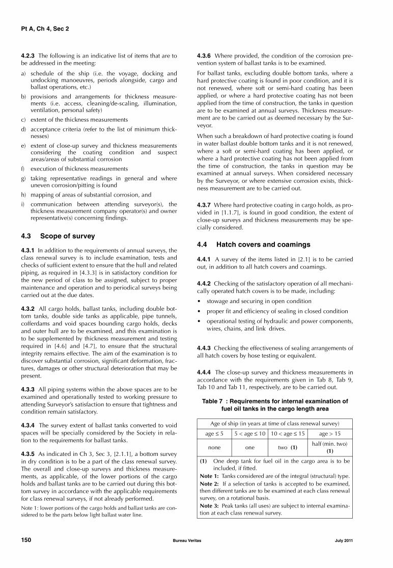
Pt A, Ch 4, Sec 2
4.2.3 The following is an indicative list of items that are tobe addressed in the meeting:
a) schedule of the ship (i.e. the voyage, docking andundocking manoeuvres, periods alongside, cargo andballast operations, etc.)
b) provisions and arrangements for thickness measure-ments (i.e. access, cleaning/de-scaling, illumination,ventilation, personal safety)
c) extent of the thickness measurements
d) acceptance criteria (refer to the list of minimum thick-nesses)
e) extent of close-up survey and thickness measurementsconsidering the coating condition and suspectareas/areas of substantial corrosion
f) execution of thickness measurements
g) taking representative readings in general and whereuneven corrosion/pitting is found
h) mapping of areas of substantial corrosion, and
i) communication between attending surveyor(s), thethickness measurement company operator(s) and ownerrepresentative(s) concerning findings.
4.3 Scope of survey
4.3.1 In addition to the requirements of annual surveys, theclass renewal survey is to include examination, tests andchecks of sufficient extent to ensure that the hull and relatedpiping, as required in [4.3.3] is in satisfactory condition forthe new period of class to be assigned, subject to propermaintenance and operation and to periodical surveys beingcarried out at the due dates.
4.3.2 All cargo holds, ballast tanks, including double bot-tom tanks, double side tanks as applicable, pipe tunnels,cofferdams and void spaces bounding cargo holds, decksand outer hull are to be examined, and this examination isto be supplemented by thickness measurement and testingrequired in [4.6] and [4.7], to ensure that the structuralintegrity remains effective. The aim of the examination is todiscover substantial corrosion, significant deformation, frac-tures, damages or other structural deterioration that may bepresent.
4.3.3 All piping systems within the above spaces are to beexamined and operationally tested to working pressure toattending Surveyor’s satisfaction to ensure that tightness andcondition remain satisfactory.
4.3.4 The survey extent of ballast tanks converted to voidspaces will be specially considered by the Society in rela-tion to the requirements for ballast tanks.
4.3.5 As indicated in Ch 3, Sec 3, [2.1.1], a bottom surveyin dry condition is to be a part of the class renewal survey.The overall and close-up surveys and thickness measure-ments, as applicable, of the lower portions of the cargoholds and ballast tanks are to be carried out during this bot-tom survey in accordance with the applicable requirementsfor class renewal surveys, if not already performed.
Note 1: lower portions of the cargo holds and ballast tanks are con-sidered to be the parts below light ballast water line.
4.3.6 Where provided, the condition of the corrosion pre-vention system of ballast tanks is to be examined.
For ballast tanks, excluding double bottom tanks, where ahard protective coating is found in poor condition, and it isnot renewed, where soft or semi-hard coating has beenapplied, or where a hard protective coating has not beenapplied from the time of construction, the tanks in questionare to be examined at annual surveys. Thickness measure-ment are to be carried out as deemed necessary by the Sur-veyor.
When such a breakdown of hard protective coating is foundin water ballast double bottom tanks and it is not renewed,where a soft or semi-hard coating has been applied, orwhere a hard protective coating has not been applied fromthe time of construction, the tanks in question may beexamined at annual surveys. When considered necessaryby the Surveyor, or where extensive corrosion exists, thick-ness measurement are to be carried out.
4.3.7 Where hard protective coating in cargo holds, as pro-vided in [1.1.7], is found in good condition, the extent ofclose-up surveys and thickness measurements may be spe-cially considered.
4.4 Hatch covers and coamings
4.4.1 A survey of the items listed in [2.1] is to be carriedout, in addition to all hatch covers and coamings.
4.4.2 Checking of the satisfactory operation of all mechani-cally operated hatch covers is to be made, including:
• stowage and securing in open condition
• proper fit and efficiency of sealing in closed condition
• operational testing of hydraulic and power components,wires, chains, and link drives.
4.4.3 Checking the effectiveness of sealing arrangements ofall hatch covers by hose testing or equivalent.
4.4.4 The close-up survey and thickness measurements inaccordance with the requirements given in Tab 8, Tab 9,Tab 10 and Tab 11, respectively, are to be carried out.
Table 7 : Requirements for internal examination offuel oil tanks in the cargo length area
Age of ship (in years at time of class renewal survey)
age ≤ 5 5 < age ≤ 10 10 < age ≤ 15 age > 15
none one two (1)half (min. two)
(1)
(1) One deep tank for fuel oil in the cargo area is to beincluded, if fitted.
Note 1: Tanks considered are of the integral (structural) type.Note 2: If a selection of tanks is accepted to be examined,then different tanks are to be examined at each class renewalsurvey, on a rotational basis.Note 3: Peak tanks (all uses) are subject to internal examina-tion at each class renewal survey.
150 Bureau Veritas July 2011
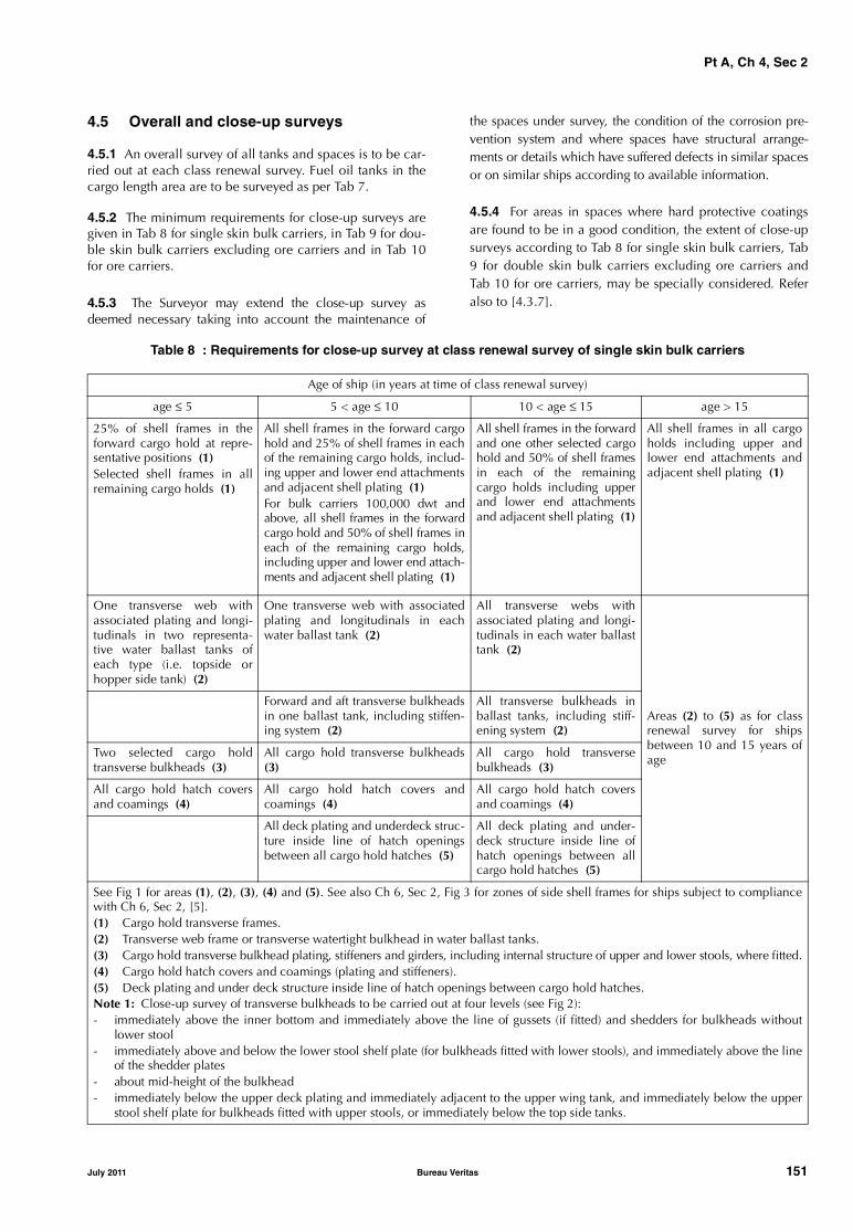
Pt A, Ch 4, Sec 2
4.5 Overall and close-up surveys
4.5.1 An overall survey of all tanks and spaces is to be car-ried out at each class renewal survey. Fuel oil tanks in thecargo length area are to be surveyed as per Tab 7.
4.5.2 The minimum requirements for close-up surveys aregiven in Tab 8 for single skin bulk carriers, in Tab 9 for dou-ble skin bulk carriers excluding ore carriers and in Tab 10for ore carriers.
4.5.3 The Surveyor may extend the close-up survey asdeemed necessary taking into account the maintenance of
the spaces under survey, the condition of the corrosion pre-vention system and where spaces have structural arrange-ments or details which have suffered defects in similar spacesor on similar ships according to available information.
4.5.4 For areas in spaces where hard protective coatingsare found to be in a good condition, the extent of close-upsurveys according to Tab 8 for single skin bulk carriers, Tab9 for double skin bulk carriers excluding ore carriers andTab 10 for ore carriers, may be specially considered. Referalso to [4.3.7].
Table 8 : Requirements for close-up survey at class renewal survey of single skin bulk carriers
Age of ship (in years at time of class renewal survey)
age ≤ 5 5 < age ≤ 10 10 < age ≤ 15 age > 15
25% of shell frames in theforward cargo hold at repre-sentative positions (1)Selected shell frames in allremaining cargo holds (1)
All shell frames in the forward cargohold and 25% of shell frames in eachof the remaining cargo holds, includ-ing upper and lower end attachmentsand adjacent shell plating (1)For bulk carriers 100,000 dwt andabove, all shell frames in the forwardcargo hold and 50% of shell frames ineach of the remaining cargo holds,including upper and lower end attach-ments and adjacent shell plating (1)
All shell frames in the forwardand one other selected cargohold and 50% of shell framesin each of the remainingcargo holds including upperand lower end attachmentsand adjacent shell plating (1)
All shell frames in all cargoholds including upper andlower end attachments andadjacent shell plating (1)
One transverse web withassociated plating and longi-tudinals in two representa-tive water ballast tanks ofeach type (i.e. topside orhopper side tank) (2)
One transverse web with associatedplating and longitudinals in eachwater ballast tank (2)
All transverse webs withassociated plating and longi-tudinals in each water ballasttank (2)
Areas (2) to (5) as for classrenewal survey for shipsbetween 10 and 15 years ofage
Forward and aft transverse bulkheadsin one ballast tank, including stiffen-ing system (2)
All transverse bulkheads inballast tanks, including stiff-ening system (2)
Two selected cargo holdtransverse bulkheads (3)
All cargo hold transverse bulkheads(3)
All cargo hold transversebulkheads (3)
All cargo hold hatch coversand coamings (4)
All cargo hold hatch covers andcoamings (4)
All cargo hold hatch coversand coamings (4)
All deck plating and underdeck struc-ture inside line of hatch openingsbetween all cargo hold hatches (5)
All deck plating and under-deck structure inside line ofhatch openings between allcargo hold hatches (5)
See Fig 1 for areas (1), (2), (3), (4) and (5). See also Ch 6, Sec 2, Fig 3 for zones of side shell frames for ships subject to compliancewith Ch 6, Sec 2, [5].(1) Cargo hold transverse frames.(2) Transverse web frame or transverse watertight bulkhead in water ballast tanks.(3) Cargo hold transverse bulkhead plating, stiffeners and girders, including internal structure of upper and lower stools, where fitted.(4) Cargo hold hatch covers and coamings (plating and stiffeners).(5) Deck plating and under deck structure inside line of hatch openings between cargo hold hatches.Note 1: Close-up survey of transverse bulkheads to be carried out at four levels (see Fig 2):- immediately above the inner bottom and immediately above the line of gussets (if fitted) and shedders for bulkheads without
lower stool- immediately above and below the lower stool shelf plate (for bulkheads fitted with lower stools), and immediately above the line
of the shedder plates- about mid-height of the bulkhead- immediately below the upper deck plating and immediately adjacent to the upper wing tank, and immediately below the upper
stool shelf plate for bulkheads fitted with upper stools, or immediately below the top side tanks.
July 2011 Bureau Veritas 151
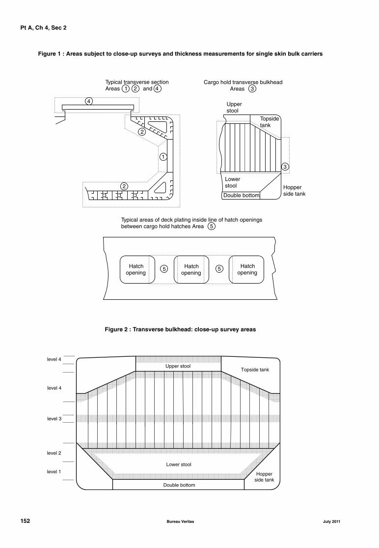
Pt A, Ch 4, Sec 2
Figure 1 : Areas subject to close-up surveys and thickness measurements for single skin bulk carriers
Figure 2 : Transverse bulkhead: close-up survey areas
Typical transverse sectionAreas 1 2 and 4
4
2
1
2
Cargo hold transverse bulkhead Areas 3
Upperstool
Topsidetank
3
Lowerstool Hopper
side tankDouble bottom
Typical areas of deck plating inside line of hatch openingsbetween cargo hold hatches Area 5
5 5 Hatchopening
Hatchopening
Hatchopening
level 4
level 4
level 3
level 2
level 1
Upper stool
Lower stool
Double bottom
Topside tank
Hopperside tank
152 Bureau Veritas July 2011

Pt A, Ch 4, Sec 2
Table 9 : Requirements for close-up survey at class renewal survey of double skin bulk carriers, excluding ore carriers
Age of ship (in years at time of class renewal survey)
age ≤ 5 5 < age ≤ 10 10 < age ≤ 15 age > 15
One transverse web with asso-ciated plating and longitudinalsin two representative water bal-last tanks of each type (this is toinclude the foremost topsideand double side water ballasttanks on either side) (1)
One transverse web with asso-ciated plating and longitudinalsas applicable in each waterballast tank (1)
All transverse webs with asso-ciated plating and longitudinalsas applicable in each waterballast tank (1)
All transverse webs with asso-ciated plating and longitudinalsas applicable in each waterballast tank (1)
Forward and aft transversebulkheads including stiffeningsystem in a transverse sectionincluding topside, hopper sideand double side ballast tanks(1)
All transverse bulkheadsincluding stiffening system ineach water ballast tank (1)
All transverse bulkheadsincluding stiffening system ineach water ballast tank (1)
25% of ordinary transverseweb frames in the foremostdouble side tanks (2)
25% of ordinary transverseweb frames in all double sidetanks (2)
All ordinary transverse webframes in all double side tanks(2)
Areas (3) to (5) as for classrenewal survey for shipsbetween 10 and 15 years ofage
Two selected cargo hold trans-verse bulkheads, includinginternal structure of upper andlower stools, where fitted (3)
One transverse bulkhead ineach cargo hold, includinginternal structure of upper andlower stools, where fitted (3)
All cargo hold transverse bulk-heads, including internal struc-ture of upper and lower stools,where fitted (3)
All cargo hold hatch coversand coamings (platings andstiffeners) (4)
All cargo hold hatch coversand coamings (platings andstiffeners) (4)
All cargo hold hatch coversand coamings (platings andstiffeners) (4)
All deck plating and underdeckstructure inside line of hatchopenings between all cargohold hatches (5)
All deck plating and underdeckstructure inside line of hatchopenings between all cargohold hatches (5)
(1) Transverse web frame or watertight transverse bulkhead in topside, hopper side and double side ballast tanks. In fore and aftpeak tanks, transverse web frame means a complete transverse web frame ring including adjacent structural members.
(2) Ordinary transverse frame in double side tanks.(3) Cargo hold transverse bulkheads plating, stiffeners and girders.(4) Cargo hold hatch covers and coamings.(5) Deck plating and underdeck structure inside line of hatch openings between cargo hold hatches. Note 1: See Fig 3 and Fig 4 for areas (1), (2), (3), (4) and (5).Note 2: Close-up survey of transverse bulkheads to be carried out at four levels (see Fig 2):- immediately above the inner bottom and immediately above the line of gussets (if fitted) and shedders for ships without lower
tool- immediately above and below the lower stool shelf plate (for those ships fitted with lower stools), and immediately above the line
of the shedder plates- about mid-height of the bulkhead- immediately below the upper deck plating and immediately adjacent to the upper wing tank, and immediately below the upper
stool shelf plate (for those ships fitted with upper stools), or immediately below the topside tanks.
July 2011 Bureau Veritas 153

Pt A, Ch 4, Sec 2
Table 10 : Requirements for close-up survey at class renewal survey of ore carriers
Age of ship (in years at time of class renewal survey)
age ≤ 5 5 < age ≤ 10 10 < age ≤ 15 age > 15
One web frame ring complete,including adjacent structuralmembers, in a ballast wingtank (1)
All web frame rings complete,including adjacent structuralmembers, in a ballast wingtank (1)
All web frame rings complete,including adjacent structuralmembers, in each ballast tank(1)
As for class renewal survey forships between 10 and 15 yearsof age
One transverse bulkhead lowerpart, including girder systemand adjacent structural mem-bers, in a ballast tank (1)
One deck transverse, includ-ing adjacent deck structuralmembers, in each remainingballast tank (1)
All transverse bulkheads com-plete, including girder systemand adjacent structural mem-bers, in each ballast tank (1)
Forward and aft transversebulkheads complete, includinggirder system and adjacentstructural members, in a ballastwing tank (1)
One web frame ring complete,including adjacent structuralmembers, in each wing voidspace (1)
One transverse bulkhead lowerpart, including girder systemand adjacent structural mem-bers, in each remaining ballasttank (1)
Additional web frame rings invoid spaces, as deemed neces-sary by the Society (1)
Two selected cargo hold trans-verse bulkheads, includinginternal structure of upper andlower stools, where fitted (3)
One transverse bulkhead ineach cargo hold, includinginternal structure of upper andlower stools, where fitted (3)
All cargo hold transverse bulk-heads, including internal struc-ture of upper and lower stools,where fitted (3)
Areas (3) to (5) as for classrenewal survey for shipsbetween 10 and 15 years ofage
All cargo hold hatch coversand coamings (platings andstiffeners) (4)
All cargo hold hatch coversand coamings (platings andstiffeners) (4)
All cargo hold hatch coversand coamings (platings andstiffeners) (4)
All deck plating and underdeckstructure inside line of hatchopenings between all cargohold hatches (5)
All deck plating and underdeckstructure inside line of hatchopenings between all cargohold hatches (5)
(1) Transverse web frame or watertight transverse bulkhead in ballast wing tanks and void spaces. In fore and aft peak tanks, trans-verse web frame means a complete transverse web frame ring including adjacent structural members.
(2) (not used in this Table).(3) Cargo hold transverse bulkheads plating, stiffeners and girders.(4) Cargo hold hatch covers and coamings.(5) Deck plating and underdeck structure inside line of hatch openings between cargo hold hatches. Note 1: See Fig 3 and Fig 4 for areas (1), (3), (4) and (5) (area (2) not used).Note 2: Close-up survey of transverse bulkheads to be carried out at four levels (see Fig 2):Level 1 : Immediately above the inner bottom and immediately above the line of gussets (if fitted) and shedders for ships without
lower stool.Level 2 : Immediately above and below the lower stool shelf plate (for those ships fitted with lower stools), and immediately
above the line of the shedder plates.Level 3 : About mid-height of the bulkhead.Level 4 : Immediately below the upper deck plating and immediately adjacent to the upper wing tank, and immediately below
the upper stool shelf plate (for those ships fitted with upper stools), or immediately below the topside tanks.
154 Bureau Veritas July 2011

Pt A, Ch 4, Sec 2
Figure 3 : Areas subject to close-up surveys and thickness measurements for double skin bulk carriers
Typical transverse sectionAreas 1 and 4
4
1
1
Cargo hold transverse bulkhead Area 3
Upper stoolTopside tank
3
Lower stool
Hopperside tankDouble bottom tank
Typical areas of deck plating and underdeck structure inside lineof hatch openings between cargo hold hatches - Area 5
5 5 Hatchopening
Hatchopening
Hatchopening
Ordinary transverse framein double skin tank
Area 2
July 2011 Bureau Veritas 155
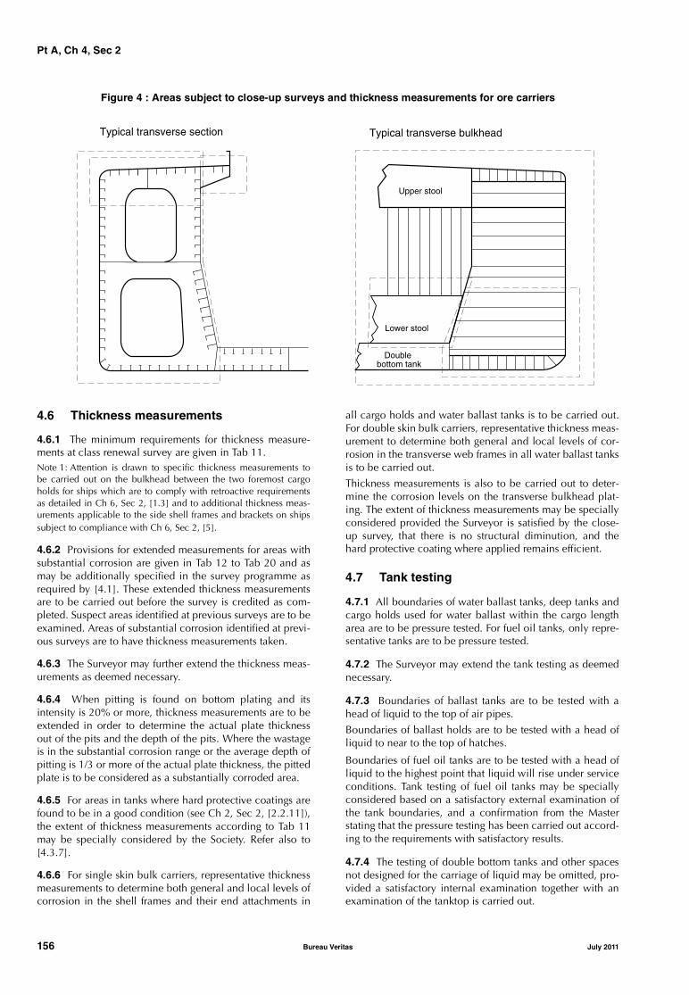
Pt A, Ch 4, Sec 2
Figure 4 : Areas subject to close-up surveys and thickness measurements for ore carriers
4.6 Thickness measurements
4.6.1 The minimum requirements for thickness measure-ments at class renewal survey are given in Tab 11.Note 1: Attention is drawn to specific thickness measurements tobe carried out on the bulkhead between the two foremost cargoholds for ships which are to comply with retroactive requirementsas detailed in Ch 6, Sec 2, [1.3] and to additional thickness meas-urements applicable to the side shell frames and brackets on shipssubject to compliance with Ch 6, Sec 2, [5].
4.6.2 Provisions for extended measurements for areas withsubstantial corrosion are given in Tab 12 to Tab 20 and asmay be additionally specified in the survey programme asrequired by [4.1]. These extended thickness measurementsare to be carried out before the survey is credited as com-pleted. Suspect areas identified at previous surveys are to beexamined. Areas of substantial corrosion identified at previ-ous surveys are to have thickness measurements taken.
4.6.3 The Surveyor may further extend the thickness meas-urements as deemed necessary.
4.6.4 When pitting is found on bottom plating and itsintensity is 20% or more, thickness measurements are to beextended in order to determine the actual plate thicknessout of the pits and the depth of the pits. Where the wastageis in the substantial corrosion range or the average depth ofpitting is 1/3 or more of the actual plate thickness, the pittedplate is to be considered as a substantially corroded area.
4.6.5 For areas in tanks where hard protective coatings arefound to be in a good condition (see Ch 2, Sec 2, [2.2.11]),the extent of thickness measurements according to Tab 11may be specially considered by the Society. Refer also to[4.3.7].
4.6.6 For single skin bulk carriers, representative thicknessmeasurements to determine both general and local levels ofcorrosion in the shell frames and their end attachments in
all cargo holds and water ballast tanks is to be carried out.For double skin bulk carriers, representative thickness meas-urement to determine both general and local levels of cor-rosion in the transverse web frames in all water ballast tanksis to be carried out.
Thickness measurements is also to be carried out to deter-mine the corrosion levels on the transverse bulkhead plat-ing. The extent of thickness measurements may be speciallyconsidered provided the Surveyor is satisfied by the close-up survey, that there is no structural diminution, and thehard protective coating where applied remains efficient.
4.7 Tank testing
4.7.1 All boundaries of water ballast tanks, deep tanks andcargo holds used for water ballast within the cargo lengtharea are to be pressure tested. For fuel oil tanks, only repre-sentative tanks are to be pressure tested.
4.7.2 The Surveyor may extend the tank testing as deemednecessary.
4.7.3 Boundaries of ballast tanks are to be tested with ahead of liquid to the top of air pipes.
Boundaries of ballast holds are to be tested with a head ofliquid to near to the top of hatches.
Boundaries of fuel oil tanks are to be tested with a head ofliquid to the highest point that liquid will rise under serviceconditions. Tank testing of fuel oil tanks may be speciallyconsidered based on a satisfactory external examination ofthe tank boundaries, and a confirmation from the Masterstating that the pressure testing has been carried out accord-ing to the requirements with satisfactory results.
4.7.4 The testing of double bottom tanks and other spacesnot designed for the carriage of liquid may be omitted, pro-vided a satisfactory internal examination together with anexamination of the tanktop is carried out.
Lower stool
Double bottom tank
Upper stool
Typical transverse section Typical transverse bulkhead
156 Bureau Veritas July 2011
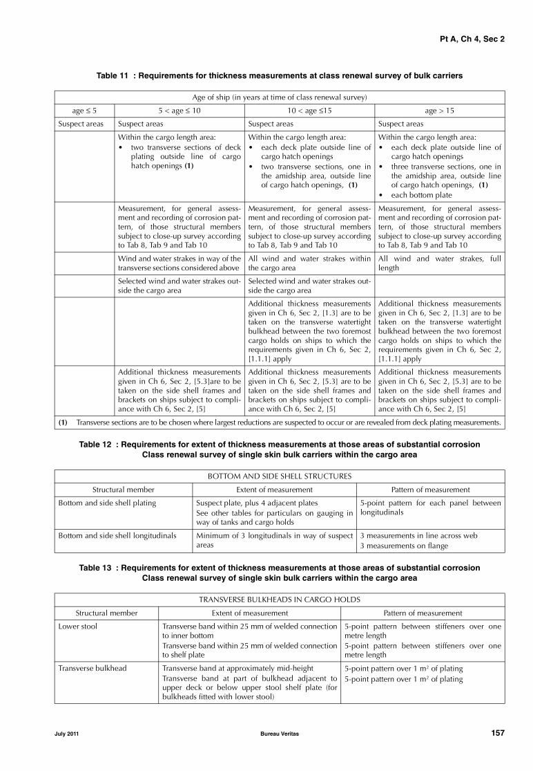
Pt A, Ch 4, Sec 2
Table 11 : Requirements for thickness measurements at class renewal survey of bulk carriers
Table 12 : Requirements for extent of thickness measurements at those areas of substantial corrosionClass renewal survey of single skin bulk carriers within the cargo area
Table 13 : Requirements for extent of thickness measurements at those areas of substantial corrosionClass renewal survey of single skin bulk carriers within the cargo area
Age of ship (in years at time of class renewal survey)
age ≤ 5 5 < age ≤ 10 10 < age ≤15 age > 15
Suspect areas Suspect areas Suspect areas Suspect areas
Within the cargo length area: • two transverse sections of deck
plating outside line of cargohatch openings (1)
Within the cargo length area:• each deck plate outside line of
cargo hatch openings• two transverse sections, one in
the amidship area, outside lineof cargo hatch openings, (1)
Within the cargo length area: • each deck plate outside line of
cargo hatch openings• three transverse sections, one in
the amidship area, outside lineof cargo hatch openings, (1)
• each bottom plate
Measurement, for general assess-ment and recording of corrosion pat-tern, of those structural memberssubject to close-up survey accordingto Tab 8, Tab 9 and Tab 10
Measurement, for general assess-ment and recording of corrosion pat-tern, of those structural memberssubject to close-up survey accordingto Tab 8, Tab 9 and Tab 10
Measurement, for general assess-ment and recording of corrosion pat-tern, of those structural memberssubject to close-up survey accordingto Tab 8, Tab 9 and Tab 10
Wind and water strakes in way of thetransverse sections considered above
All wind and water strakes withinthe cargo area
All wind and water strakes, fulllength
Selected wind and water strakes out-side the cargo area
Selected wind and water strakes out-side the cargo area
Additional thickness measurementsgiven in Ch 6, Sec 2, [1.3] are to betaken on the transverse watertightbulkhead between the two foremostcargo holds on ships to which therequirements given in Ch 6, Sec 2,[1.1.1] apply
Additional thickness measurementsgiven in Ch 6, Sec 2, [1.3] are to betaken on the transverse watertightbulkhead between the two foremostcargo holds on ships to which therequirements given in Ch 6, Sec 2,[1.1.1] apply
Additional thickness measurementsgiven in Ch 6, Sec 2, [5.3]are to betaken on the side shell frames andbrackets on ships subject to compli-ance with Ch 6, Sec 2, [5]
Additional thickness measurementsgiven in Ch 6, Sec 2, [5.3] are to betaken on the side shell frames andbrackets on ships subject to compli-ance with Ch 6, Sec 2, [5]
Additional thickness measurementsgiven in Ch 6, Sec 2, [5.3] are to betaken on the side shell frames andbrackets on ships subject to compli-ance with Ch 6, Sec 2, [5]
(1) Transverse sections are to be chosen where largest reductions are suspected to occur or are revealed from deck plating measurements.
BOTTOM AND SIDE SHELL STRUCTURES
Structural member Extent of measurement Pattern of measurement
Bottom and side shell plating Suspect plate, plus 4 adjacent platesSee other tables for particulars on gauging inway of tanks and cargo holds
5-point pattern for each panel betweenlongitudinals
Bottom and side shell longitudinals Minimum of 3 longitudinals in way of suspectareas
3 measurements in line across web3 measurements on flange
TRANSVERSE BULKHEADS IN CARGO HOLDS
Structural member Extent of measurement Pattern of measurement
Lower stool Transverse band within 25 mm of welded connectionto inner bottomTransverse band within 25 mm of welded connectionto shelf plate
5-point pattern between stiffeners over onemetre length5-point pattern between stiffeners over onemetre length
Transverse bulkhead Transverse band at approximately mid-heightTransverse band at part of bulkhead adjacent toupper deck or below upper stool shelf plate (forbulkheads fitted with lower stool)
5-point pattern over 1 m2 of plating5-point pattern over 1 m2 of plating
July 2011 Bureau Veritas 157

Pt A, Ch 4, Sec 2
Table 14 : Requirements for extent of thickness measurements at those areas of substantial corrosionClass renewal survey of single skin bulk carriers within the cargo area
Table 15 : Requirements for extent of thickness measurements at those areas of substantial corrosionClass renewal survey of single skin bulk carriers within the cargo area
Table 16 : Requirements for extent of thickness measurements at those areas of substantial corrosionClass renewal survey of single skin bulk carriers within the cargo area
DECK STRUCTURE AND HATCH COVERS
Structural member Extent of measurement Pattern of measurement
Cross deck strip plating Suspect cross deck strip plating 5-point pattern between underdeck stiffeners overone metre length
Underdeck stiffeners Transverse members 5-point pattern at each end and mid-span
Longitudinal members 5-point pattern on both web and flange
Hatch covers Skirt: 3 locations on each side and each end 5-point pattern at each location
3 longitudinal bands, outboard strakes (2) and centreline strake (1)
5-point measurement each band
Hatch coamings Both sides and ends of coaming: one band lower 1/3 and one band upper 2/3 of coaming
5-point measurement each band
Topside water ballast tanks Transverse watertight bulkhead:
(a) lower 1/3 of bulkhead (a) 5-point pattern over 1 m2 of plating
(b) upper 2/3 of bulkhead (b) 5-point pattern over 1 m2 of plating
(c) stiffeners (c) 5-point pattern over 1 m length
Two representative transverse wash bulkheads:
(a) lower 1/3 of bulkhead (a) 5-point pattern over 1 m2 of plating
(b) upper 2/3 of bulkhead (b) 5-point pattern over 1 m2 of plating
(c) stiffeners (c) 5-point pattern over 1 m length
Three representative bays of sloped plating:
(a) lower 1/3 of tank (a) 5-point pattern over 1 m2 of plating
(b) upper 2/3 of tank (b) 5-point pattern over 1 m2 of plating
Longitudinals: suspect and adjacent 5-point pattern both web and flange over 1 m length
Main deck plating Suspect plates and adjacent 5-point pattern over 1 m2 of plating
Main deck longitudinals Minimum of 3 longitudinals where plating measured
5-point pattern both web and flange over 1 m length
Web frames/transverses Suspect plates 5-point pattern over 1 m2 of plating
DOUBLE BOTTOM AND HOPPER STRUCTURE
Structural member Extent of measurement Pattern of measurement
Inner bottom plating Suspect plate plus all adjacent plates 5-point pattern for each panel between longitudinalsover one metre length
Inner bottom longitudinals Three longitudinals where plates measured 3 measurements in line across and 3 measurements onflange
Longitudinal girders and transverse floors
Suspect plates 5-point pattern over approximately 1 m2 of plating
Watertight bulkheads(floors and girders)
(a) lower 1/3 of tank (a) 5-point pattern over 1 m2 of plating
(b) upper 2/3 of tank (b) 5-point pattern alternate plates over 1 m2 of plating
Transverse web frames Suspect plate 5-point pattern over 1 m2 of plating
CARGO HOLDS
Structural member Extent of measurement Pattern of measurement
Side shell frames Suspect frame and each adjacent (a) At each end and mid-span: 5-point pattern of both weband flange
(b) 5-point pattern within 25 mm of welded attachment toboth shell and lower sloped plate
158 Bureau Veritas July 2011

Pt A, Ch 4, Sec 2
Table 17 : Requirements for extent of thickness measurements at those areas of substantial corrosionClass renewal survey of double skin bulk carriers within the cargo length area
Table 18 : Requirements for extent of thickness measurements at those areas of substantial corrosionClass renewal survey of double skin bulk carriers within the cargo length area
BOTTOM, INNER BOTTOM AND HOPPER STRUCTURE
Structural member Extent of measurement Pattern of measurement
Bottom, inner bottom and hopper structure plating
Minimum of 3 bays across double bottomtank, including aft bayMeasurements around and under all suctionbell mouths
5-point pattern for each panel between longitudinalsand floors
Bottom, inner bottom and hopper structure longitudinals
Minimum of 3 longitudinals in each baywhere bottom plating measured
3 measurements in line across flange and 3 measure-ments on the vertical web
Bottom girders, including the watertight ones
At fore and aft watertight floors and in centreof tanks
Vertical line of single measurements on girder platingwith 1 measurement between each panel stiffener, ora minimum of 3 measurements
Bottom floors, including the watertight ones
3 floors in the bays where bottom platingmeasured, with measurements at both endsand middle
5-point pattern over 2 square metre area
Hopper structure web frame ring
3 floors in the bays where bottom platingmeasured
5-point pattern over 1 square metre of platingSingle measurements on flange
Hopper structure transverse watertight bulkhead or swash bulkhead
• lower 1/3 of bulkhead • 5-point pattern over 1 square metre of plating
• upper 2/3 of bulkhead • 5-point pattern over 2 square metre of plating
• stiffeners (minimum of 3) • for web, 5-point pattern over span (2 measure-ments across web at each end and one at centreof span). For flange, single measurements at eachend and centre of span
Panel stiffening Where applicable Single measurements
DECK STRUCTURE INCLUDING CROSS STRIPS, MAIN CARGO HATCHWAYS,HATCH COVERS, COAMINGS AND TOPSIDE TANKS
Structural member Extent of measurement Pattern of measurement
Cross deck strip plating Suspect cross deck strip plating 5-point pattern between underdeck stiffeners over 1 metre length
Underdeck stiffeners Transverse members 5-point pattern at each end and mid span
Longitudinal members 5-point pattern on both web and flange
Hatch covers Side and end skirts, each 3 locations 5-point pattern at each location
3 longitudinal bands: 2 outboard strakes and 1 centreline strake
5-point measurement each band
Hatch coamings Each side and end of coaming, one band lower 1/3, one band upper 2/3 of coaming
5-point measurement each band i.e. end or side coaming
Topside ballast tanks a) Watertight transverse bulkheads:
• lower 1/3 of bulkhead 5-point pattern over 1 square metre of plating
• upper 2/3 of bulkhead 5-point pattern over 1 square metre of plating
• stiffeners 5-point pattern over 1 metre length
Topside ballast tanks b) Two representative swash transverse bulkheads:
• lower 1/3 of bulkhead 5-point pattern over 1 square metre of plating
• upper 2/3 of bulkhead 5-point pattern over 1 square metre of plating
• stiffeners 5-point pattern over 1 metre length
Topside ballast tanks c) Three representative bays of slope plating:
• lower 1/3 of tank 5-point pattern over 1 square metre of plating
• upper 2/3 of tank 5-point pattern over 1 square metre of plating
Topside ballast tanks d) Longitudinals, suspect and adjacent 5-point pattern on both web and flange over 1 metre length
Main deck plating Suspect plates and adjacent (4) 5-point pattern over 1 square metre of plating
Main deck longitudinals Suspect plates 5-point pattern on both web and flange over 1 metre length
Web frames / Transverses Suspect plates 5-point pattern over 1 square metre
July 2011 Bureau Veritas 159
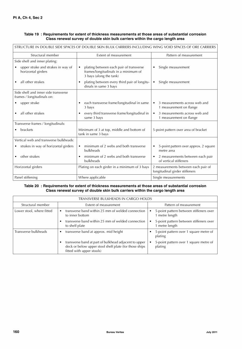
Pt A, Ch 4, Sec 2
Table 19 : Requirements for extent of thickness measurements at those areas of substantial corrosionClass renewal survey of double skin bulk carriers within the cargo length area
Table 20 : Requirements for extent of thickness measurements at those areas of substantial corrosionClass renewal survey of double skin bulk carriers within the cargo length area
STRUCTURE IN DOUBLE SIDE SPACES OF DOUBLE SKIN BULK CARRIERS INCLUDING WING VOID SPACES OF ORE CARRIERS
Structural member Extent of measurement Pattern of measurement
Side shell and inner plating:
• upper strake and strakes in way of horizontal girders
• plating between each pair of transverse frames/longitudinals in a minimum of 3 bays (along the tank)
• Single measurement
• all other strakes • plating between every third pair of longitu-dinals in same 3 bays
• Single measurement
Side shell and inner side transverse frames / longitudinals on:
• upper strake • each transverse frame/longitudinal in same 3 bays
• 3 measurements across web and 1 measurement on flange
• all other strakes • every third transverse frame/longitudinal in same 3 bays
• 3 measurements across web and 1 measurement on flange
Transverse frames / longitudinals:
• brackets Minimum of 3 at top, middle and bottom of tank in same 3 bays
5-point pattern over area of bracket
Vertical web and transverse bulkheads:
• strakes in way of horizontal girders • minimum of 2 webs and both transverse bulkheads
• 5-point pattern over approx. 2 square metre area
• other strakes • minimum of 2 webs and both transverse bulkheads
• 2 measurements between each pair of vertical stiffeners
Horizontal girders Plating on each girder in a minimum of 3 bays 2 measurements between each pair of longitudinal girder stiffeners
Panel stiffening Where applicable Single measurements
TRANSVERSE BULKHEADS IN CARGO HOLDS
Structural member Extent of measurement Pattern of measurement
Lower stool, where fitted • transverse band within 25 mm of welded connection to inner bottom
• 5-point pattern between stiffeners over 1 metre length
• transverse band within 25 mm of welded connection to shelf plate
• 5-point pattern between stiffeners over 1 metre length
Transverse bulkheads • transverse band at approx. mid height • 5-point pattern over 1 square metre of plating
• transverse band at part of bulkhead adjacent to upper deck or below upper stool shelf plate (for those ships fitted with upper stools)
• 5-point pattern over 1 square metre of plating
160 Bureau Veritas July 2011
Pt A, Ch 4, Sec 3
SECTION 3 OIL TANKERS AND COMBINATION CARRIERS
1 General
1.1 Application
1.1.1 The requirements of this Section apply to all self-pro-pelled ships which have been assigned one of the followingservice notations:• oil tanker ESP (whether of single or double hull con-
struction)• combination carrier/OBO ESP
• combination carrier/OOC ESP.
Note 1: A double hull oil tanker is a ship which is constructed pri-marily for the carriage of oil (MARPOL Annex I cargoes) in bulk,which have the cargo tanks protected by a double hull whichextends for the entire length of the cargo area, consisting of doublesides and double bottom spaces for the carriage of water ballast orvoid spaces. The requirements of this Section for double hull tank-ers are also applicable to existing double hull tankers not comply-ing with MARPOL Regulation 13F, but having a U-shaped midshipsection.
1.1.2 The requirements for hull surveys apply to the surveysof the hull structure and piping systems in way of cargotanks, pump rooms, cofferdams, pipe tunnels and voidspaces within the cargo area and all ballast tanks. They areadditional to the requirements applicable to the remainderof the ship, given in Part A, Chapter 3 according to the rele-vant surveys.
1.1.3 The requirements contain the minimum extent ofexamination, thickness measurements and tank testing.When substantial corrosion, as defined in Ch 2, Sec 2,[2.2.7], and/or structural defects are found, the survey is tobe extended and is to include additional close-up surveyswhen necessary.
1.1.4 Thickness measurements of structures in areas whereclose-up surveys are required are to be carried out simulta-neously with close-up surveys.
1.1.5 In all cases the extent of thickness measurements is tobe sufficient as to represent the actual average condition.
1.1.6 When, in any survey, thickness measurements arerequired:
• the procedure detailed in Ch 2, Sec 2, [2.3] is to beapplied
• the thickness measurement operator is to attend the sur-vey planning meeting held prior to commencing thesurvey.
1.1.7 The requirements for machinery surveys apply to sur-veys of the machinery and equipment in the cargo area ordedicated to cargo service systems and are additional tothose given in Part A, Chapter 3 for all ships.
1.2 Documentation on board
1.2.1 The Owner is to obtain, supply and maintain docu-mentation on board as specified in [1.2.2] and [1.2.3],which is to be readily available for examination by the Sur-veyor. The documentation is to be kept on board for the life-time of the ship.
1.2.2 A survey report file is to be a part of the documenta-tion on board consisting of:
• reports of structural surveys
• hull condition evaluation report (summarising theresults of class renewal surveys)
• thickness measurement reports.
The survey report file is also to be available in the Owner'smanagement office.
1.2.3 The following additional supporting documentationis to be available on board:
• main structural plans of cargo tanks and ballast tanks
• previous repair history
• cargo and ballast history
• extent of use of inert gas system and tank cleaning pro-cedures
• ship’s personnel reports on:
- structural deterioration/defects in general
- leakage in bulkheads and piping systems
- condition of coatings or corrosion prevention sys-tems, if any
• survey program, as required in [6.1], until such time asthe class renewal survey or intermediate survey, asapplicable, has been completed
• any other information that may help to identify criticalstructural areas and/or suspect areas requiring inspec-tion.
1.2.4 Prior to survey, the Surveyor examines the documen-tation on board and its contents, which are used as a basisfor the survey.
1.3 Reporting and evaluation of surveys
1.3.1 The data and information on the structural conditionof the ship collected during survey are evaluated for accept-ability and structural integrity of the ship's cargo area.
1.3.2 In case of oil tankers of 130 m in length and upwards(as defined in the International Convention on Load Lines inforce), the ship's longitudinal strength is to be evaluated byusing the thickness of structural members measured,renewed and reinforced, as appropriate, during the class
July 2011 Bureau Veritas 161
Pt A, Ch 4, Sec 3
renewal survey carried out after the ship reached 10 yearsof age in accordance with the criteria for longitudinalstrength of the ship's hull girder for oil tankers specified inCh 4, App 1.
The final result of evaluation of the ship's longitudinalstrength, after renewal or reinforcement work of structuralmembers, if carried out as a result of initial evaluation, is tobe reported as a part of the hull condition evaluation report.
1.3.3 When a survey is split between different survey sta-tions, a report is to be made for each portion of the survey.A list of items examined and/or tested (pressure testing,thickness measurements etc.) and an indication of whetherthe item has been credited, are to be made available to thenext attending Surveyor(s), prior to continuing or complet-ing the survey.
1.3.4 A hull condition evaluation report (summarizing theresults of class renewal surveys) is issued by the Society tothe Owner, who is to place it on board the ship for refer-ence at future surveys. The hull condition evaluation reportis endorsed by the Society.
1.4 Conditions for survey
1.4.1 In order to enable the attending surveyor(s) to carryout the survey, provisions for proper and safe access are tobe agreed between the Owner and the Society.
Details of the means of access are to be provided in the sur-vey planning questionnaire.
In cases where the provisions of safety and required accessare judged by the attending surveyor(s) not to be adequate,the survey of the spaces involved is not to proceed.
1.4.2 The surveyor(s) are to always be accompanied by atleast one responsible person, assigned by the Owner, expe-rienced in tank and enclosed spaces inspection. In additiona back-up team of at least two experienced persons is to bestationed at the hatch opening of the tank or space that isbeing surveyed. The back-up team is to continuouslyobserve the work in the tank or space and is to keep lifesav-ing and evacuation equipment ready for use.
1.5 Access to structures
1.5.1 For overall survey, means are to be provided to ena-ble the surveyor(s) to examine the hull structure in a safeand practical way.
1.5.2 For close-up survey, one or more of the followingmeans for access, acceptable to the Surveyor, is to be pro-vided:
• permanent staging and passages through structures
• temporary staging and passages through structures
• lifts and movable platforms
• boats or rafts
• portable ladders
• other equivalent means.
2 Annual survey - Hull items
2.1 Weather decks
2.1.1 The survey is to include:
• examination of cargo tank openings, including gaskets,covers, coamings and screens
• examination of cargo tank pressure/vacuum valves andflame screens
• examination of flame screens on vents to all bunker,oily-ballast and oily slop tanks and void spaces
• examination of cargo, crude oil washing, bunker, ballastand vent piping systems, including remote controlvalves, safety valves and various safety devices, as wellas vent masts and headers
• confirmation that wheelhouse doors and windows, side-scuttles and windows in superstructure and deckhouseends facing the cargo area are in satisfactory condition.
2.2 Cargo pump rooms and pipe tunnels
2.2.1 The survey is to include:
• examination of all pump room bulkheads and pipe tun-nels (if any) for signs of oil leakage or fractures and, inparticular, the sealing arrangements of penetrations inthese bulkheads
• examination of the condition of all piping systems, incargo pump rooms and pipe tunnels (if any)
• examination of the bilge and ballast arrangements.
2.3 Ballast tanks
2.3.1 Ballast tanks are to be internally examined whenrequired as a consequence of the results of the classrenewal survey or the intermediate survey.
2.3.2 When considered necessary by the Surveyor, or whenextensive corrosion exists, thickness measurements are tobe carried out and if the results of these thickness measure-ments indicate that substantial corrosion is found, the extentof thickness measurements is to be increased in accordancewith the requirements of Tab 4 or Tab 5. These extendedthickness measurements are to be carried out before thesurvey is credited as completed. Suspect areas identified atprevious surveys are to be examined. Areas of substantialcorrosion identified at previous surveys are to have thick-ness measurements taken.
2.4 Emergency towing arrangement
2.4.1 The Owner or his representative is to declare to theattending Surveyor that no significant alterations have beenmade, without prior approval from the Society, to the equip-ment and arrangements fitted on board in accordance withthe provisions given in Pt B, Ch 10, Sec 4, [4].
162 Bureau Veritas July 2011

Pt A, Ch 4, Sec 3
2.4.2 The survey is to include:
• an examination, as far as practicable, of the emergencytowing arrangement
• confirmation that the aft towing arrangement is pre-rigged and forward chafing gear is secured to the strong-point
• confirmation of the proper functioning of the light,where it is provided, on the pick-up gear marker buoy.
2.5 Safe access to tanker bows
2.5.1 The access to bow arrangement is to be examined, asapplicable.
3 Annual survey - Cargo machinery items
3.1 Cargo area and cargo pump rooms
3.1.1 The Owner or his representative is to declare to theattending Surveyor that no modifications or alterationswhich might impair safety have been made to the variousinstallations in dangerous zones without prior approvalfrom the Society.
The survey is to include:
• check of the protection of cargo pump room, as applica-ble, and in particular, check of:
- temperature sensing devices for bulkheads glandsand alarms
- interlock between lighting and ventilation
- gas detection system
- bilge level monitoring devices and alarms
• examination of the emergency lighting in cargo pumprooms of ships constructed after 1st July 2002
• confirmation that potential sources of ignition in or nearthe cargo pump rooms, such as loose gear, excessiveproduct in bilge, excessive vapours, combustible mate-rials, etc., are eliminated and that access ladders are insatisfactory condition
• examination, as far as practicable, of cargo, bilge, bal-last and stripping pumps for excessive gland seal leak-age, verification of proper operation of electrical andmechanical remote operating and shutdown devicesand operation of the pump room bilge system, andchecking that pump foundations are intact
• confirmation that the ventilation system, including port-able equipment, if any, of all spaces in the cargo area(including cargo pump rooms) is operational, ducting isintact, dampers are operational and screens are clean
• confirmation that electrical equipment in dangerouszones, cargo pump rooms and other spaces is in satis-factory condition and has been properly maintained
• confirmation that the remote operation of the cargopump room bilge system is satisfactory
• examination of the cargo heating system, as appropriate
• examination of the cargo-transfer arrangement and con-firmation that the ship's cargo hoses are suitable fortheir intended purpose and in satisfactory condition
• confirmation that any special arrangement made forbow or stern loading/unloading is in satisfactory condi-tion and test of the means of communication andremote shutdown of the cargo pumps.
3.2 Instrumentation and safety devices
3.2.1 The survey is to include:• examination of cargo tank gauging devices, high level
alarms and valves associated with overflow control• verification that installed pressure gauges on cargo dis-
charge lines are properly operational• confirmation that the required gas detection instruments
are on board and satisfactory arrangements have beenmade for the supply of any required vapour detectiontubes
• confirmation that devices provided for measuring thetemperature of the cargo, if any, operate satisfactorily.
3.3 Fire-fighting systems in cargo area
3.3.1 The survey is to include:• external examination of piping and cut-out valves of
fixed fire-fighting systems related to cargo tanks andcargo pump rooms
• confirmation, as far as practicable and when appropri-ate, that the remote means for closing the various open-ings are operable
• examination of the appropriate portable fire-extinguish-ing equipment for the cargoes to be carried in accord-ance with the relevant requirements given in Ch 3, Sec1, [3.4.3]
• examination of fire-fighting systems of any type fitted onboard such as deck foam, water-spraying, etc., as appli-cable in accordance with the relevant requirementsgiven in Ch 3, Sec 1, [3.4].
3.4 Inert gas system
3.4.1 The survey is to include:• external examination of the whole system, to check the
condition of all piping, including vent piping above theupper deck in the cargo tank area and overboard dis-charges through the shell so far as practicable, and asso-ciated components to verify, in particular, the absenceof signs of corrosion and leakage of gas, water or otherliquid from inert gas and water piping systems or fromthe pressure/vacuum breaking device
• check of proper operation of both inert gas blowers• check of proper operation of ventilation system required
for scrubber room (if any)• check of deck water seal for automatic water filling and
draining• check of absence of water carry over in the inert gas
from the deck water seal and check of the condition ofthe non-return valve
• check of proper operation of all remotely operated orautomatically controlled valves and, in particular, of theflue gas isolating valve located on the inert gas supplymain after the blowers
July 2011 Bureau Veritas 163
Pt A, Ch 4, Sec 3
• check of proper operation of the interlocking feature fit-ted to prevent soot blowers from operating when theinert gas system is working
• check that the gas pressure regulating valve automati-cally closes when gas blowers are stopped
• check, as far as practicable and using simulated condi-tions where necessary, of the following alarms andsafety devices of the inert gas system:- high oxygen content of gas in the inert gas main- low gas pressure in the inert gas main- low pressure in the supply to the deck water seal- high temperature of gas in the inert gas main,
including automatic shutdown devices- low water pressure to the scrubber, including auto-
matic shutdown devices- accuracy of portable and fixed oxygen measuring
equipment by means of calibration gases- high water level in the scrubber, including auto-
matic shutdown devices- failure of the inert gas blowers- failure of the power supply to the automatic control
system for the gas regulating valve and to the instru-mentation for continuous indication and permanentrecording of pressure and oxygen content in theinert gas main
- high pressure of gas in the inert gas main• check, when practicable, of the proper operation of the
inert gas system on completion of the checks listedabove.
4 Intermediate survey - Hull items
4.1 General
4.1.1 The survey of weather decks is to include:• examination, as far as applicable, of cargo, crude oil
washing, bunker, ballast, steam and vent piping systemsas well as vent masts and headers. If upon examinationthere is any doubt as to the condition of the piping, thepiping may be required to be pressure tested, thicknessmeasured or both
• confirmation, if applicable, that cargo pipes are electri-cally bonded to the hull
• examination of vent line drainage arrangements.
4.2 Ships between 5 and 10 years of age
4.2.1 For single hull oil tankers and combination carriers,all ballast tanks are to be examined.When considered necessary by the Surveyor, thicknessmeasurements and testing are to be carried out to ensurethat the structural integrity remains effective.
4.2.2 For double hull oil tankers, an overall survey of repre-sentative salt water ballast tanks selected by the Surveyor isto be carried out.If such overall survey reveals no visible structural defects,the examination may be limited to a verification that thehard protective coating remains in good condition.
4.2.3 A ballast tank is to be examined at subsequent annualsurveys where:
• a hard protective coating has not been applied from thetime of construction, or
• a soft or semi-hard coating has been applied, or
• substantial corrosion is found within the tank, or
• the hard protective coating is found to be in less thangood condition and the hard protective coating is notrepaired to the satisfaction of the Surveyor.
Thickness measurement is to be carried out as deemed nec-essary by the Surveyor.
4.2.4 In addition to the requirements above, suspect areasidentified at previous surveys are to be examined.
4.3 Ships between 10 and 15 years of age
4.3.1 The scope of intermediate survey of ships between 10and 15 years of age is the scope of the preceding classrenewal survey of hull, as detailed in [6] with bottom surveyin dry condition or bottom in water survey as applicable.However, pressure testing of all cargo and ballast tanks andthe requirements for longitudinal strength evaluation of hullgirder as required in [6.5.5] are not required unless deemednecessary by the attending Surveyor.
4.4 Ships over 15 years of age
4.4.1 The scope of intermediate survey of ships over 15years of age is the scope of the preceding class renewal sur-vey of hull, as detailed in [6] with bottom survey in dry con-dition, except that pressure testing of ballast and cargotanks and the requirements for longitudinal strength evalua-tion of hull girder as required in [6.5.5] is not requiredunless deemed necessary by the Surveyor.
The overall and close-up surveys and thickness measure-ments, as applicable, of the lower portions of the cargotanks and water ballast tanks are to be carried out duringthe bottom survey in accordance with the applicablerequirements for intermediate surveys, if not already per-formed.
Lower portions of the cargo and ballast tanks are consid-ered to be the parts below light ballast water line.
The requirements of [6.8] are not applicable.
5 Intermediate survey - Cargo machinery items
5.1 Cargo area and cargo pump rooms
5.1.1 A general examination of the electrical equipmentand cables in dangerous zones such as cargo pump roomsand areas adjacent to cargo tanks is to be carried out fordefective and non-certified safe type electrical equipmentand fixtures, non-approved lighting and fixtures, andimproperly installed or defective or dead-end wiring.
164 Bureau Veritas July 2011

Pt A, Ch 4, Sec 3
5.1.2 The electrical insulation resistance of the electricalequipment and circuits terminating in or passing throughthe dangerous zones is to be tested; however, in caseswhere a proper record of testing is maintained, considera-tion may be given to accepting recent test readings effectedby the ship’s personnel.
5.1.3 The satisfactory condition of the cargo heating systemis to be verified.
5.2 Inert gas system
5.2.1 The following is to be carried out:
• main parts such as the scrubber, washing machines,blowers, deck water seal and non-return valve are to beopened out as considered necessary and examined
• gas distribution lines and shut-off valves, including sootblower interlocking devices, are to be examined asdeemed necessary
• all automatic shutdown devices and alarms are to beexamined and tested.
6 Class renewal survey - Hull items
6.1 Survey programme and preparation for hull survey
6.1.1 The Owner in cooperation with the Society is to workout a specific Survey Programme prior to the commence-ment of any part of:
• the class renewal survey
• the intermediate survey for oil tankers over 10 years ofage.
The survey programme is to be in a written format. The sur-vey is not to commence until the Survey Programme hasbeen agreed.
Prior to the development of the Survey Programme, the sur-vey planning questionnaire is to be completed by theOwner and forwarded to the Society.
The survey programme at intermediate survey may consistof the survey programme at the previous class renewal sur-vey supplemented by the hull condition evaluation report ofthat class renewal survey and later relevant survey reports.
The survey programme is to be worked out taking intoaccount any amendments to the survey requirements afterthe last class renewal survey carried out.
6.1.2 In developing the survey programme, the followingdocumentation is to be collected and consulted with a viewto selecting tanks, areas and structural elements to be exam-ined:
a) survey status and basic ship information
b) documentation on board, as described in [1.2.2] and[1.2.3]
c) main structural plans of cargo and ballast tanks (scant-lings drawings), including information regarding use ofhigh-tensile steels (HTS)
d) Hull Condition Evaluation Report
e) relevant previous damage and repair history
f) relevant previous survey and inspection reports fromboth the Society and the Owner
g) cargo and ballast history for the last 3 years, includingcarriage of cargo under heated conditions
h) details of the inert gas plant and tank cleaning proce-dures
i) information and other relevant data regarding conver-sion or modification of the ship’s cargo and ballast tankssince the time of construction
j) description and history of the coating and corrosionprotection system (including previous class notations), ifany
k) inspections by the Owner’s personnel during the last 3years with reference to structural deterioration in gen-eral, leakages in tank boundaries and piping and condi-tion of the coating and corrosion protection system ifany
l) information regarding the relevant maintenance levelduring operation including port state control reports ofinspection containing hull related deficiencies, SafetyManagement System non-conformities relating to hullmaintenance, including the associated correctiveaction(s), and
m) any other information that will help identify suspectareas and critical structural areas.
6.1.3 The submitted survey programme is to account forand comply, as a minimum, with the requirements of Tab 1or Tab 2, Tab 3 and Tab 6, for close-up survey, thicknessmeasurements and tank testing, respectively, and is toinclude relevant information including at least:
a) basic ship information and particulars
b) main structural plans of cargo and ballast tanks (scant-ling drawings), including information regarding use ofhigh tensile steels (HTS)
c) arrangement of tanks
d) list of tanks with information on their use, extent ofcoatings and corrosion protection systems
e) conditions for survey (e.g., information regarding tankcleaning, gas freeing, ventilation, lighting, etc.)
f) provisions and methods for access to structures
g) equipment for surveys
h) identification of tanks and areas for close-up survey (see[6.4])
i) identification of areas and sections for thickness meas-urement (see [6.5])
j) identification of tanks for tank testing (see [6.6])
k) identification of the thickness measurement company
l) damage experience related to the ship in question, and
m) critical structural areas and suspect areas, where rele-vant.
6.1.4 The Society is to advise the Owner of the maximumacceptable structural corrosion diminution levels applicableto the ship.
July 2011 Bureau Veritas 165

Pt A, Ch 4, Sec 3
6.2 Survey planning meeting
6.2.1 The establishment of proper preparation and theclose co-operation between the attending surveyor(s) andthe owner's representatives onboard prior to and during thesurvey are an essential part in the safe and efficient conductof the survey. During the survey on board, safety meetingsare to be held regularly.
6.2.2 Prior to commencement of any part of the renewaland intermediate survey, a survey planning meeting is to beheld between the attending surveyor(s), the owner's repre-sentative in attendance, the thickness measurement com-pany representative, where involved, and the master of theship or an appropriately qualified representative appointedby the master or Company for the purpose to ascertain thatall the arrangements envisaged in the survey programme arein place, so as to ensure the safe and efficient conduct ofthe survey work to be carried out. See also [1.1.6].
6.2.3 The following is an indicative list of items that are tobe addressed in the meeting:
a) schedule of the ship (i.e. the voyage, docking andundocking manoeuvres, periods alongside, cargo andballast operations, etc.)
b) provisions and arrangements for thickness measure-ments (i.e. access, cleaning/de-scaling, illumination,ventilation, personal safety)
c) extent of the thickness measurements
d) acceptance criteria (refer to the list of minimum thick-nesses)
e) extent of close-up survey and thickness measurementsconsidering the coating condition and suspectareas/areas of substantial corrosion
f) execution of thickness measurements
g) taking representative readings in general and whereuneven corrosion/pitting is found
h) mapping of areas of substantial corrosion, and
i) communication between attending surveyor(s), thethickness measurement company operator(s) and ownerrepresentative(s) concerning findings.
6.3 Scope of survey
6.3.1 In addition to the requirements of annual surveys, theclass renewal survey is to include examination, tests andchecks of sufficient extent to ensure that the hull and relatedpiping are in satisfactory condition for the new period ofclass to be assigned, subject to proper maintenance andoperation and to periodical surveys being carried out at thedue dates.
6.3.2 All cargo tanks, ballast tanks, including double bot-tom tanks, pump rooms, pipe tunnels, cofferdams and voidspaces bounding cargo tanks, decks and outer hull are to beexamined, and this examination is to be supplemented bythickness measurement and testing as required in [6.5] and[6.6], to ensure that the structural integrity remains effec-tive. The aim of the examination is to discover substantialcorrosion, significant deformation, fractures, damages orother structural deterioration, that may be present.
6.3.3 As indicated in Ch 3, Sec 3, [2.1.1], a bottom surveyin dry condition is to be a part of the class renewal survey.The overall and close-up surveys and thickness measure-ments, as applicable, of the lower portions of the cargotanks and ballast tanks are to be carried out during this bot-tom survey in accordance with the applicable requirementsfor class renewal surveys, if not already performed.Lower portions of the cargo and ballast tanks are consid-ered to be the parts below light ballast water line.
6.3.4 Where provided, the condition of the corrosion pre-vention system of cargo tanks is to be examined.A ballast tank is to be examined at subsequent annual sur-veys where:• a hard protective coating has not been applied from the
time of construction, or• a soft or semi-hard coating has been applied, or• substantial corrosion is found within the tank, or • the hard protective coating is found to be in less than
good condition and the hard protective coating is notrepaired to the satisfaction of the Surveyor.
Thickness measurement is to be carried out as deemed nec-essary by the Surveyor.
Figure 1 : Areas subject to close-up surveys and thickness measurements - Single hull oil tanker
5
22
1 4
3
Girder
Girder
Girder
3
4
Typical transverse section Typical transverse bulkhead
166 Bureau Veritas July 2011

Pt A, Ch 4, Sec 3
Table 1 : Close-up survey at class renewal survey of single hull oil tankers and combination carriers
6.4 Overall and close-up surveys
6.4.1 Each class renewal survey is to include an overall sur-vey of all tanks and spaces.
6.4.2 The minimum requirements for close-up surveys aregiven in Tab 1 for single hull oil tankers and combinationcarriers or Tab 2 for double hull oil tankers.
6.4.3 The Surveyor may extend the close-up survey asdeemed necessary, taking into account the maintenance of
the tanks under survey, the condition of the corrosion pre-vention system and also in the following cases:
• where tanks have structural arrangements or detailswhich have suffered defects in similar tanks or on simi-lar ships according to available information
• where tanks have structures approved with reducedscantlings.
6.4.4 For areas in tanks where hard protective coatings arefound to be in good condition, as defined in Ch 2, Sec 2,[2.2.11], the extent of close-up surveys required accordingto Tab 1 or Tab 2 may be specially considered.
Age of ship (in years at time of class renewal survey)
age ≤ 5 5 < age ≤ 10 10 < age ≤ 15 age > 15
One web frame ring �:- in a ballast wing tank, if any,
or- in a cargo wing tank used pri-
marily for water ballast
All web frame rings �:- in a ballast wing tank, if any,
or- in a cargo wing tank used pri-
marily for water ballast
All web frame rings � in all bal-last tanksAll web frame rings � in a cargowing tankA minimum of 30% (1) of all webframe rings � in each remainingcargo wing tank
As class renewal surveyfor ships between 10 and15 years of age
One deck transverse � in a cargotank
One deck transverse �: - in each remaining ballast
tank, if any- in a cargo wing tank- in two cargo centre tanks
Additional transverseareas as deemed neces-sary by the Society
Both transverse bulkheads �:- in a wing ballast tank, if any,
or- in a cargo wing tank used pri-
marily for water ballast
All transverse bulkheads (area �)in all cargo and ballast tanks
One transverse bulkhead � in aballast tankOne transverse bulkhead � in acargo wing tankOne transverse bulkhead � in acargo centre tank
One transverse bulkhead � ineach remaining ballast tankOne transverse bulkhead � in acargo wing tankOne transverse bulkhead � intwo cargo centre tanks
A minimum of 30% (1) of deckand bottom transverses � in eachcargo centre tank
Additional web frame ring(s) �,as considered necessary by theSurveyor
(1) The 30% is to be rounded up to the next whole integer.Note 1: See Fig 1 or Fig 2 for areas �, �, �, � and �.� : Complete transverse web frame ring including adjacent structural member.� : Deck transverse including adjacent deck structural members.� : Transverse bulkhead complete, including girder system and adjacent structural members.� : Transverse bulkhead lower part, including girder system and adjacent structural members.� : Deck and bottom transverse, including adjacent structural members.
July 2011 Bureau Veritas 167

Pt A, Ch 4, Sec 3
Figure 2 : Areas subject to close-up surveys and thickness measurements - Combination carrier / OOC
Table 2 : Close-up survey at class renewal survey of double hull oil tankers
Age of ship (in years at time of class renewal survey)
age ≤ 5 5 < age ≤ 10 10 < age ≤ 15 age > 15
One web frame � in a bal-last tank (1)
All web frames � in a ballast tank (1)The knuckle area � and the upper part(5 meters approximately) of one webframe in each remaining ballast tank
All web frames � in all ballasttanks
As class renewal surveyfor ships between 10and 15 years of age
One deck transverse � in acargo tank
One deck transverse � in two cargotanks
All web frames � including decktransverse and cross ties, if fitted,in a cargo tankOne web frame � including decktransverse and cross ties, if fitted,in each remaining cargo tank
Additional transverseareas as deemed neces-sary by the Society
One transverse bulkhead �in a ballast tank (1)
One transverse bulkhead � in eachballast tank (1)
All transverse bulkheads in allcargo � and ballast tanks �
One transverse bulkhead �in a cargo wing tank (2)
One transverse bulkhead � in a cargowing tank (2)
One transverse bulkhead �in a cargo centre tank
One transverse bulkhead � in twocargo centre tanks
(1) Ballast tank means double bottom tank plus double side tank plus double deck tank, as applicable, even if these tanks are sep-arate.
(2) Where no centre cargo tank is fitted (as in the case of centre longitudinal bulkhead), transverse bulkheads in wing tanks are tobe surveyed.
Note 1: �, �, �, �, �, � and � are areas to be subjected to close-up surveys and thickness measurements (see Fig 3).� : Web frame in a ballast tank means vertical web in side tank, hopper web in hopper tank, floor in double bottom tank
and deck transverse in double deck tank (where fitted), including adjacent structural members. In fore and aft peaktank, web frame means a complete transverse web frame ring including adjacent structural members.
� : Deck transverse including adjacent deck structural members (or external structure on deck in way of the tank, whereapplicable).
� : Transverse bulkhead complete in cargo tanks, including girder system adjacent structural members (such as longitu-dinal bulkheads) and internal structure of lower and upper stools, where fitted.
� : Transverse bulkhead complete in ballast tanks, including girder system and adjacent structural members, such aslongitudinal bulkheads, girders in double bottom tanks, inner bottom plating, hopper side, inner hull longitudinalbulkhead, connecting brackets.
� : Transverse bulkhead lower part in cargo tank, including girder system, adjacent structural members (such as longitu-dinal bulkheads) and internal structure of lower stool where fitted.
� : Knuckle area is the area of the web frame around the connections of the slope hopper plating to the inner hull bulk-head and the inner bottom plating, up to 2 meters from the corners both on the bulkhead and the double bottom.
� : Web frame in a cargo tank means deck transverse, longitudinal bulkhead vertical girder and cross ties, where fitted,including adjacent structural members.
2
2 and 5
1
3
4
4
Lower stool
Double bottom tank
Upper stool
Typical transverse section Typical transverse bulkhead
168 Bureau Veritas July 2011

Pt A, Ch 4, Sec 3
Figure 3 : Areas subject to close-up surveys and thickness measurements - Double hull oil tanker
6.5 Thickness measurements
6.5.1 The minimum requirements for thickness measure-ments at class renewal survey are given in Tab 3.
6.5.2 Provisions for extended measurements for areas withsubstantial corrosion are given in Tab 4 for single hull oiltankers and combination carriers or Tab 5 for double hulloil tankers and as may be additionally specified in the sur-vey program as required in [6.1]. These extended thicknessmeasurements are to be carried out before the survey iscredited as completed.
Suspect areas identified at previous surveys are to be exam-ined.
Areas of substantial corrosion identified at previous surveysare to have thickness measurements taken.
The Surveyor may further extend the thickness measure-ments as deemed necessary.
6.5.3 When pitting is found on bottom plating and itsintensity is 20% or more, thickness measurements are to beextended in order to determine the actual plate thicknessout of the pits and the depth of the pits. Where the wastageis in the substantial corrosion range or the average depth ofpitting is 1/3 or more of the actual plate thickness, the pittedplate is to be considered as a substantially corroded area.
6.5.4 For areas in tanks where hard protective coatings arefound to be in good condition as defined in Ch 2, Sec 2,[2.2.11], the extent of thickness measurements according toTab 3 may be specially considered.
6.5.5 On oil tankers of 130 m in length and upwards (asdefined in the International Convention on Load Lines inforce) and more than 10 years of age, the longitudinalstrength of the ship's hull girder is to be evaluated in com-pliance with the requirements of Ch 4, App 1 on the basis ofthe thickness of the structures measured, renewed or rein-forced, as appropriate, during the class renewal survey.
6.6 Tank testing
6.6.1 The requirements for tank testing at class renewal sur-vey are given in Tab 6.
6.6.2 The Surveyor may extend the tank testing as deemednecessary.
6.6.3 Boundaries of ballast tanks are to be tested with ahead of liquid to the top of air pipes.Boundaries of cargo tanks are to be tested to the highestpoint that liquid will rise under service conditions
For double hull oil tankers, the testing of double bottomtanks and other spaces not designed for the carriage of liq-uid may be omitted, provided a satisfactory internal exami-nation together with an examination of the tanktop iscarried out.
2
2
1
7
6
67
4
3 3
5 5
July 2011 Bureau Veritas 169

Pt A, Ch 4, Sec 3
Table 3 : Thickness measurements at class renewal survey of oil tankers and combination carriers
Table 4 : Extended thickness measurements at those areas of substantial corrosionSingle hull oil tankers and combination carriers
Age of ship (in years at time of class renewal survey)
age ≤ 5 5 < age ≤ 10 10 < age ≤ 15 age > 15
Suspect areas Suspect areas Suspect areas Suspect areas
One section of deck plating forthe full beam of the ship withinthe cargo area (in way of a bal-last tank, if any, or a cargo tankused primarily for water bal-last)
Within the cargo area: • each deck plate (1)• 1 transverse section (2)
Within the cargo area:• each deck plate (1) • 2 transverse sections (2) (3) • all wind and water strakes
Within the cargo area: • each deck plate (1) • 3 transverse sections (2) (3) • each bottom plate
Measurements, for generalassessment and recording ofcorrosion pattern, of thosestructural members subject toclose-up survey according toTab 1 and Tab 2
Measurements, for generalassessment and recording ofcorrosion pattern, of thosestructural members subject toclose-up survey according toTab 1 and Tab 2
Measurements, for generalassessment and recording ofcorrosion pattern, of thosestructural members subject toclose-up survey according toTab 1 and Tab 2
Measurements, for generalassessment and recording ofcorrosion pattern, of thosestructural members subject toclose-up survey according toTab 1 and Tab 2
Selected wind and waterstrakes outside the cargo area
Selected wind and waterstrakes outside the cargo area
All wind and water strakes, fulllength
(1) For combination carriers only the deck plating outside line of cargo hold hatch openings is to be measured.(2) Transverse sections are to be chosen where the largest reductions are likely to occur or as revealed by deck plating measurements.(3) At least one section is to be within 0,5 L amidships and, where applicable, in way of a ballast tank.
BOTTOM STRUCTURE
Structural member Extent of measurement Pattern of measurement
Bottom plating Minimum of 3 bays across tank, including aft bayMeasurements around and under all suctionbell mouths
5-point pattern for each panel between longi-tudinals and webs
Bottom longitudinals Minimum of 3 longitudinals in each bay wherebottom plating measured
3 measurements in line across flange and3 measurements on vertical web
Bottom girders and brackets At fore and aft transverse bulkhead, brackettoes and in centre of tanks
Vertical line of single measurements on webplating with one measurement between eachpanel stiffener, or a minimum of 3 measure-ments.2 measurements across face flat.5-point pattern on girder/bulkhead brackets.
Bottom transverse webs 3 webs in bays where bottom plating meas-ured, with measurements at both ends andmiddle
5-point pattern over 2 square metre area.Single measurements on face flat.
Panel stiffening Where provided Single measurements
DECK STRUCTURE
Structural member Extent of measurement Pattern of measurement
Deck plating 2 bands across tank Minimum of 3 measurements per plate perband
Deck longitudinals Minimum of 3 longitudinals in each of 2 bays 3 measurements in line vertically on webs and2 measurements on flange (if fitted)
Deck girders and brackets At fore and aft transverse bulkhead, brackettoes and in centre of tanks
Vertical line of single measurements on webplating with one measurement between eachpanel stiffener, or a minimum of 3 measure-ments.2 measurements across face flat.5-point pattern on girder/bulkhead brackets.
Deck transverse webs Minimum of 2 webs, with measurements atboth ends and middle of span
5-point pattern over 2 square metre area.Single measurements on face flat.
Panel stiffening Where provided Single measurements
170 Bureau Veritas July 2011

Pt A, Ch 4, Sec 3
6.7 Cargo piping, area and pump rooms
6.7.1 Cargo and crude oil washing piping on deck andcargo and ballast piping systems within the cargo area areto be examined and operationally tested to working pres-sure to the attending Surveyor’s satisfaction to ensure thattheir tightness and condition remain satisfactory. Specialattention is to be given to any ballast piping in cargo tanksand cargo piping in ballast tanks and void spaces. Surveyorsare to be advised on all occasions when this piping, includ-ing valves and fittings, is opened during repair periods andcan be examined internally.
The surveyor may require dismantling and/or thicknessmeasurements of piping. A hydraulic test is to be carried outin the event of repair or dismantling or cargo, crude oilwashing, or ballast piping, or where doubts arise.
6.7.2 All safety valves on cargo piping and of cargo tanksare to be dismantled for examination, adjusted and, asapplicable, resealed.
6.7.3 All cargo pump room boundaries are to be generallyexamined. All gas-tight shaft sealing devices are to be exam-ined. The bottom of cargo pump rooms is to be presentedclean for the examination of stripping devices and gutters.
6.8 Emergency towing arrangement
6.8.1 The survey is to include:• an examination of the emergency towing arrangement• confirmation that the arrangement is readily available
with aft towing arrangement pre-rigged and forwardchafing gear secured to the strong-point
• an examination of the pick-up gear, towing pennant andchafing gear over the full length for possible deteriora-tion. Where the pennant line is stored in a watertightcondition and can be confirmed as being maintained,consideration may be given to waiving the requirementto examine the pennant line over the full length
• an examination of the strong-points, fairleads and pedestalroller together with their attachments to the hull structure.
SIDE SHELL AND LONGITUDINAL BULKHEADS
Structural member Extent of measurement Pattern of measurement
Deckhead and bottom strakes and strakes in way of stringer platforms
Plating between each pair of longitudinals in aminimum of 3 bays
Single measurement
All other strakes Plating between every third pair of longitudi-nals in same 3 bays
Single measurement
Longitudinals on deckhead and bottom strakes
Each longitudinal in same 3 bays 3 measurements across web and 1 measure-ment on flange
All other longitudinals Every third longitudinal in same 3 bays 3 measurements across web and 1 measure-ment on flange
Longitudinal brackets Minimum of 3 at top, middle and bottom oftank in same 3 bays
5-point pattern over area of bracket
Web frames and cross ties 3 webs with minimum of 3 locations on eachweb, including in way of cross tie connections
5-point pattern over approximately 2 squaremetre area, plus single measurements on webframe and cross tie face flats
TRANSVERSE BULKHEADS AND SWASH BULKHEADS
Structural member Extent of measurement Pattern of measurement
Deckhead and bottom strakes, and strakes in way of stringer plat-forms
Plating between pair of stiffeners at 3 loca-tions: approximately 1/4, 1/2 and 3/4 width oftank
5-point pattern between stiffeners over 1 metrelength
All other strakes Plating between pair of stiffeners at middlelocation
Single measurement
Strakes in corrugated bulkheads Plating for each change of scantling at centreof panel and at flange of fabricated connection
5-point pattern over about 1 square metre ofplating
Stiffeners Minimum of 3 typical stiffeners For web, 5-point pattern over span betweenbracket connections (2 measurements acrossweb at each bracket connection and one atcentre of span). For flange, single measure-ments at each bracket toe and at centre of span
Brackets Minimum of 3 at top, middle and bottom of tank 5-point pattern over area of bracket
Deep webs and girders Measurements at toe of bracket and at centreof span
For web, 5-point pattern over about 1 squaremetre3 measurements across face flat
Stringer platforms All stringers with measurements at both endsand middle
5-point pattern over 1 square metre of areaplus single measurements near bracket toesand on face flats
July 2011 Bureau Veritas 171
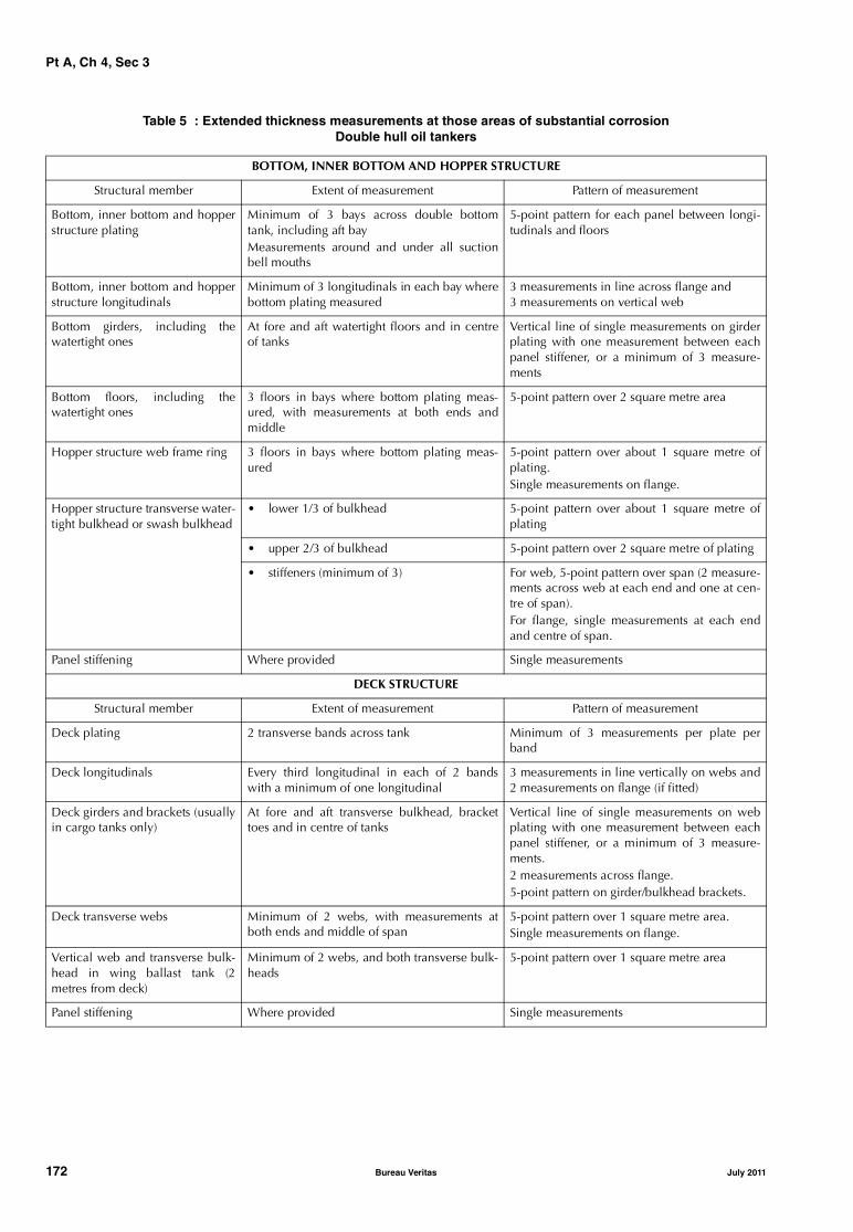
Pt A, Ch 4, Sec 3
Table 5 : Extended thickness measurements at those areas of substantial corrosionDouble hull oil tankers
BOTTOM, INNER BOTTOM AND HOPPER STRUCTURE
Structural member Extent of measurement Pattern of measurement
Bottom, inner bottom and hopperstructure plating
Minimum of 3 bays across double bottomtank, including aft bayMeasurements around and under all suctionbell mouths
5-point pattern for each panel between longi-tudinals and floors
Bottom, inner bottom and hopperstructure longitudinals
Minimum of 3 longitudinals in each bay wherebottom plating measured
3 measurements in line across flange and3 measurements on vertical web
Bottom girders, including thewatertight ones
At fore and aft watertight floors and in centreof tanks
Vertical line of single measurements on girderplating with one measurement between eachpanel stiffener, or a minimum of 3 measure-ments
Bottom floors, including thewatertight ones
3 floors in bays where bottom plating meas-ured, with measurements at both ends andmiddle
5-point pattern over 2 square metre area
Hopper structure web frame ring 3 floors in bays where bottom plating meas-ured
5-point pattern over about 1 square metre ofplating.Single measurements on flange.
Hopper structure transverse water-tight bulkhead or swash bulkhead
• lower 1/3 of bulkhead 5-point pattern over about 1 square metre ofplating
• upper 2/3 of bulkhead 5-point pattern over 2 square metre of plating
• stiffeners (minimum of 3) For web, 5-point pattern over span (2 measure-ments across web at each end and one at cen-tre of span).For flange, single measurements at each endand centre of span.
Panel stiffening Where provided Single measurements
DECK STRUCTURE
Structural member Extent of measurement Pattern of measurement
Deck plating 2 transverse bands across tank Minimum of 3 measurements per plate perband
Deck longitudinals Every third longitudinal in each of 2 bandswith a minimum of one longitudinal
3 measurements in line vertically on webs and2 measurements on flange (if fitted)
Deck girders and brackets (usuallyin cargo tanks only)
At fore and aft transverse bulkhead, brackettoes and in centre of tanks
Vertical line of single measurements on webplating with one measurement between eachpanel stiffener, or a minimum of 3 measure-ments.2 measurements across flange.5-point pattern on girder/bulkhead brackets.
Deck transverse webs Minimum of 2 webs, with measurements atboth ends and middle of span
5-point pattern over 1 square metre area.Single measurements on flange.
Vertical web and transverse bulk-head in wing ballast tank (2metres from deck)
Minimum of 2 webs, and both transverse bulk-heads
5-point pattern over 1 square metre area
Panel stiffening Where provided Single measurements
172 Bureau Veritas July 2011
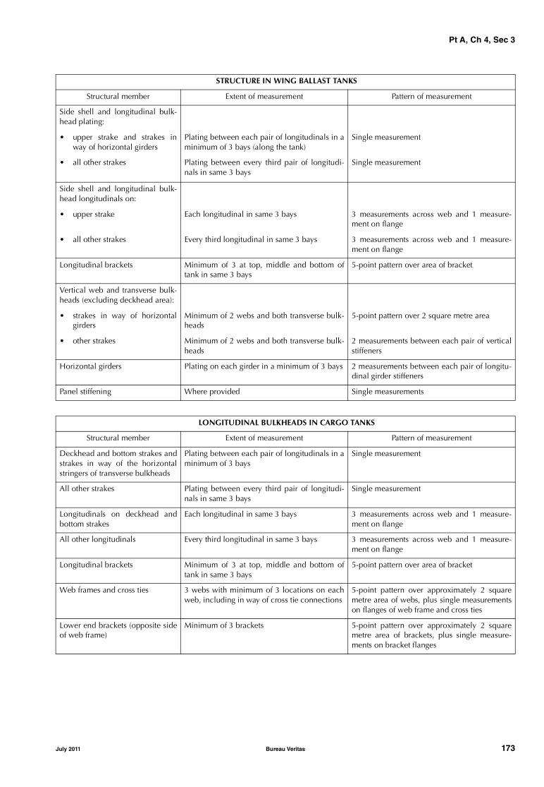
Pt A, Ch 4, Sec 3
STRUCTURE IN WING BALLAST TANKS
Structural member Extent of measurement Pattern of measurement
Side shell and longitudinal bulk-head plating:
• upper strake and strakes inway of horizontal girders
Plating between each pair of longitudinals in aminimum of 3 bays (along the tank)
Single measurement
• all other strakes Plating between every third pair of longitudi-nals in same 3 bays
Single measurement
Side shell and longitudinal bulk-head longitudinals on:
• upper strake Each longitudinal in same 3 bays 3 measurements across web and 1 measure-ment on flange
• all other strakes Every third longitudinal in same 3 bays 3 measurements across web and 1 measure-ment on flange
Longitudinal brackets Minimum of 3 at top, middle and bottom oftank in same 3 bays
5-point pattern over area of bracket
Vertical web and transverse bulk-heads (excluding deckhead area):
• strakes in way of horizontalgirders
Minimum of 2 webs and both transverse bulk-heads
5-point pattern over 2 square metre area
• other strakes Minimum of 2 webs and both transverse bulk-heads
2 measurements between each pair of verticalstiffeners
Horizontal girders Plating on each girder in a minimum of 3 bays 2 measurements between each pair of longitu-dinal girder stiffeners
Panel stiffening Where provided Single measurements
LONGITUDINAL BULKHEADS IN CARGO TANKS
Structural member Extent of measurement Pattern of measurement
Deckhead and bottom strakes andstrakes in way of the horizontalstringers of transverse bulkheads
Plating between each pair of longitudinals in aminimum of 3 bays
Single measurement
All other strakes Plating between every third pair of longitudi-nals in same 3 bays
Single measurement
Longitudinals on deckhead andbottom strakes
Each longitudinal in same 3 bays 3 measurements across web and 1 measure-ment on flange
All other longitudinals Every third longitudinal in same 3 bays 3 measurements across web and 1 measure-ment on flange
Longitudinal brackets Minimum of 3 at top, middle and bottom oftank in same 3 bays
5-point pattern over area of bracket
Web frames and cross ties 3 webs with minimum of 3 locations on eachweb, including in way of cross tie connections
5-point pattern over approximately 2 squaremetre area of webs, plus single measurementson flanges of web frame and cross ties
Lower end brackets (opposite sideof web frame)
Minimum of 3 brackets 5-point pattern over approximately 2 squaremetre area of brackets, plus single measure-ments on bracket flanges
July 2011 Bureau Veritas 173
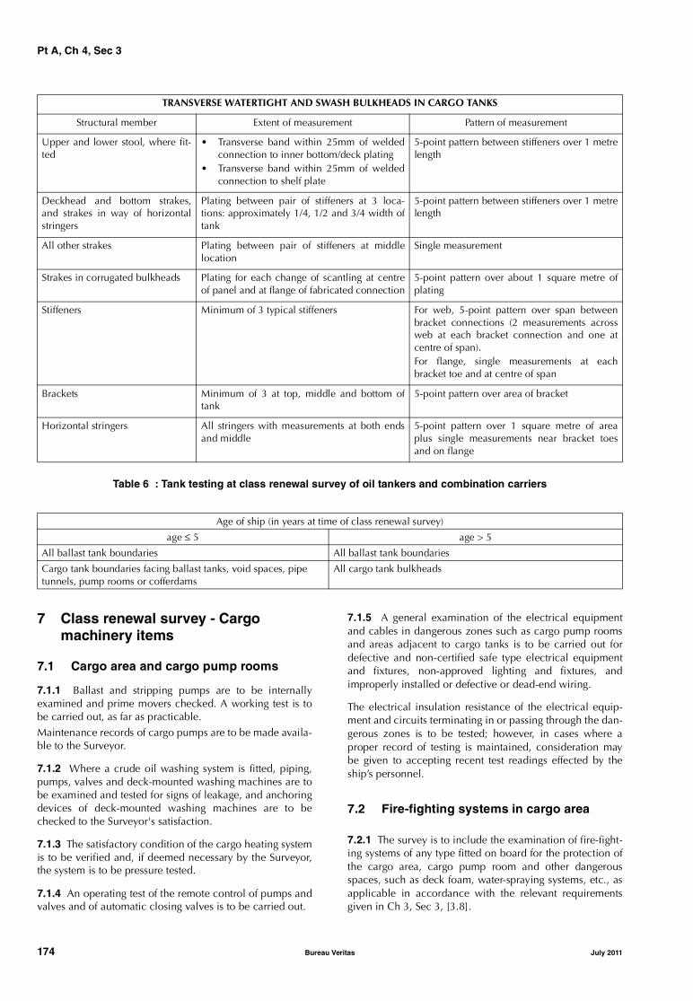
Pt A, Ch 4, Sec 3
Table 6 : Tank testing at class renewal survey of oil tankers and combination carriers
7 Class renewal survey - Cargo machinery items
7.1 Cargo area and cargo pump rooms
7.1.1 Ballast and stripping pumps are to be internallyexamined and prime movers checked. A working test is tobe carried out, as far as practicable.Maintenance records of cargo pumps are to be made availa-ble to the Surveyor.
7.1.2 Where a crude oil washing system is fitted, piping,pumps, valves and deck-mounted washing machines are tobe examined and tested for signs of leakage, and anchoringdevices of deck-mounted washing machines are to bechecked to the Surveyor's satisfaction.
7.1.3 The satisfactory condition of the cargo heating systemis to be verified and, if deemed necessary by the Surveyor,the system is to be pressure tested.
7.1.4 An operating test of the remote control of pumps andvalves and of automatic closing valves is to be carried out.
7.1.5 A general examination of the electrical equipmentand cables in dangerous zones such as cargo pump roomsand areas adjacent to cargo tanks is to be carried out fordefective and non-certified safe type electrical equipmentand fixtures, non-approved lighting and fixtures, andimproperly installed or defective or dead-end wiring.
The electrical insulation resistance of the electrical equip-ment and circuits terminating in or passing through the dan-gerous zones is to be tested; however, in cases where aproper record of testing is maintained, consideration maybe given to accepting recent test readings effected by theship’s personnel.
7.2 Fire-fighting systems in cargo area
7.2.1 The survey is to include the examination of fire-fight-ing systems of any type fitted on board for the protection ofthe cargo area, cargo pump room and other dangerousspaces, such as deck foam, water-spraying systems, etc., asapplicable in accordance with the relevant requirementsgiven in Ch 3, Sec 3, [3.8].
TRANSVERSE WATERTIGHT AND SWASH BULKHEADS IN CARGO TANKS
Structural member Extent of measurement Pattern of measurement
Upper and lower stool, where fit-ted
• Transverse band within 25mm of weldedconnection to inner bottom/deck plating
• Transverse band within 25mm of weldedconnection to shelf plate
5-point pattern between stiffeners over 1 metrelength
Deckhead and bottom strakes,and strakes in way of horizontalstringers
Plating between pair of stiffeners at 3 loca-tions: approximately 1/4, 1/2 and 3/4 width oftank
5-point pattern between stiffeners over 1 metrelength
All other strakes Plating between pair of stiffeners at middlelocation
Single measurement
Strakes in corrugated bulkheads Plating for each change of scantling at centreof panel and at flange of fabricated connection
5-point pattern over about 1 square metre ofplating
Stiffeners Minimum of 3 typical stiffeners For web, 5-point pattern over span betweenbracket connections (2 measurements acrossweb at each bracket connection and one atcentre of span).For flange, single measurements at eachbracket toe and at centre of span
Brackets Minimum of 3 at top, middle and bottom oftank
5-point pattern over area of bracket
Horizontal stringers All stringers with measurements at both endsand middle
5-point pattern over 1 square metre of areaplus single measurements near bracket toesand on flange
Age of ship (in years at time of class renewal survey)
age ≤ 5 age > 5
All ballast tank boundaries All ballast tank boundaries
Cargo tank boundaries facing ballast tanks, void spaces, pipe tunnels, pump rooms or cofferdams
All cargo tank bulkheads
174 Bureau Veritas July 2011

Pt A, Ch 4, Sec 3
7.3 Inert gas system
7.3.1 In addition to the inspections required at the interme-diate survey, the following is to be carried out:
a) an internal examination of:
• the inert gas generator, where fitted
• the scrubber
• the deck water seal including the non-return valve• the pressure/vacuum breaking device• the cooling water systems including overboard dis-
charge from the scrubber• all valves
b) a test to verify the proper operation of the system uponcompletion of all survey checks.
July 2011 Bureau Veritas 175

Pt A, Ch 4, Sec 4
SECTION 4 CHEMICAL TANKERS
1 General
1.1 Application
1.1.1 The requirements of this Section apply to all self-pro-pelled ships which have been assigned the service notationchemical tanker ESP. If such a ship is constructed with bothintegral and independent tanks, these requirements areapplicable only to that portion of the cargo length contain-ing integral tanks. Combined gas carriers/chemical tankerswith independent tanks within the hull are to be surveyedas gas carriers.
1.1.2 The requirements apply to the surveys of the hullstructure and piping systems in way of cargo tanks, pumprooms, cofferdams, pipe tunnels and void spaces within thecargo area and all ballast tanks. These requirements, how-ever, do not apply to independent tanks on deck. They areadditional to the requirements applicable to the remainderof the ship, given in Part A, Chapter 3 according to the rele-vant surveys.
1.1.3 The requirements contain the minimum extent ofexamination, thickness measurements and tank testing.When substantial corrosion and/or structural defects arefound, the survey is to be extended and is to include addi-tional close-up surveys when necessary.
1.1.4 Thickness measurements of structures in areas whereclose-up surveys are required are to be carried out simulta-neously with close-up surveys.
1.1.5 In all cases the extent of the thickness measurementsare to be sufficient as to represent the actual average condi-tion.
1.1.6 When, in any survey, thickness measurements arerequired:• the procedure detailed in Ch 2, Sec 2, [2.3] is to be
applied• the thickness measurement operator is to attend the sur-
vey planning meeting held prior to commencing thesurvey.
1.1.7 The requirements for machinery surveys apply to sur-veys of the machinery and equipment in the cargo area ordedicated to cargo service systems and are additional tothose given in Part A, Chapter 3 for all ships.
1.2 Documentation on board
1.2.1 The Owner is to obtain, supply and maintain docu-mentation on board as specified in [1.2.2] and [1.2.3],which is to be readily available for examination by the Sur-veyor. The documentation is to be kept on board for the life-time of the ship.
1.2.2 A survey report file is to be a part of the documenta-tion on board consisting of:
• reports of structural surveys
• hull condition evaluation report (summarising theresults of class renewal surveys)
• thickness measurement reports.
The survey report file is also to be available in the Owner'smanagement office.
1.2.3 The following additional supporting documentationis to be available on board:
• survey program, as required in [6.1], until such time asthe class renewal survey or intermediate survey, asapplicable, has been completed
• main structural plans of cargo and ballast tanks
• previous repair history
• cargo and ballast history
• extent of use of inert gas system and tank cleaning pro-cedures
• ship’s personnel reports on:
- structural deterioration/defects in general
- leakage in bulkheads and piping systems
- condition of coatings or corrosion prevention sys-tems, if any
• any other information that may help identify criticalstructural areas and/or suspect areas requiring inspec-tion.
1.2.4 Prior to survey, the Surveyor examines the documen-tation on board and its contents, which are used as a basisfor the survey.
1.3 Reporting and evaluation of surveys
1.3.1 The data and information on the structural conditionof the ship collected during survey are evaluated for accept-ability and structural integrity of the ship's cargo area.
1.3.2 A hull condition evaluation report (summarising theresults of class renewal surveys) is issued by the Society tothe Owner, who is to place it on board the ship for refer-ence at future surveys. The hull condition evaluation reportis endorsed by the Society.
1.3.3 When a survey is split between different survey sta-tions, a report is to be made for each portion of the survey.A list of items examined and/or tested (pressure testing,thickness measurements, etc.) and an indication of whetherthe item has been credited, are to be made available to thenext attending Surveyor(s), prior to continuing or complet-ing the survey.
176 Bureau Veritas July 2011

Pt A, Ch 4, Sec 4
1.4 Conditions for survey
1.4.1 In order to enable the attending surveyors to carry outthe survey, provisions for proper and safe access are to beagreed between the Owner and the Society.
Details of the means of access are to be provided in the sur-vey planning questionnaire.
In cases where the provisions of safety and required accessare judged by the attending surveyors not to be adequate,the survey of the spaces involved is to not proceed.
1.4.2 The surveyor(s) are to always be accompanied by atleast one responsible person, assigned by the Owner, expe-rienced in tank and enclosed spaces inspection. In additiona back-up team of at least two experienced persons is to bestationed at the hatch opening of the tank or space that isbeing surveyed. The back-up team is to continuouslyobserve the work in the tank or space and is to keep lifesav-ing and evacuation equipment ready for use.
1.5 Access to structures
1.5.1 For overall survey, means are to be provided to ena-ble the surveyor to examine the hull structure in a safe andpractical way.
1.5.2 For close-up survey, one or more of the followingmeans for access, acceptable to the Surveyor, is to be pro-vided:
• permanent staging and passages through structures
• temporary staging and passages through structures
• lifts and movable platforms
• boats or rafts
• portable ladders
• other equivalent means.
2 Annual survey - Hull items
2.1 Weather decks
2.1.1 The survey is to include:
• examination of cargo tank openings, including gaskets,covers, coamings and flame screens
• examination of cargo tank vent system, including thepressure/vacuum valves and secondary means to pre-vent over- or under-pressure and devices to prevent thepassage of flames
• examination of flame screens on vents to all bunkertanks
• examination of cargo, bunker, ballast and vent pipingsystems, including remote control valves, safety valvesand various safety devices, as well as vent masts andheaders
• confirmation that wheelhouse doors and windows, side-scuttles and windows in superstructure and deckhouseends facing the cargo area are in satisfactory condition
• confirmation that pumps, valves and pipelines are iden-tified and distinctively marked.
2.2 Cargo pump rooms and pipe tunnels
2.2.1 The survey is to include:
• examination of all pump room bulkheads and pipe tun-nels (if any) for signs of chemical cargo leakage or frac-tures and, in particular, the sealing arrangements ofpenetrations in pump room bulkheads
• examination of the condition of all piping systems, incargo pump rooms and pipe tunnels (if any)
• examination of the bilge and ballast arrangements andconfirmation that pumps and pipelines are identified.
2.3 Ballast tanks
2.3.1 Ballast tanks are to be internally examined whenrequired as a consequence of the results of the classrenewal survey or the intermediate survey; see [6.3.4] and[4.2.2], respectively.
2.3.2 When considered necessary by the Surveyor or whenextensive corrosion exists, thickness measurements are tobe carried out and if the results of these thickness measure-ments indicate that substantial corrosion is found, the extentof thickness measurements is to be increased in accordancewith Tab 3. These extended thickness measurements are tobe carried out before the survey is credited as completed.
Suspect areas identified at previous surveys are to be exam-ined.
Areas of substantial corrosion identified at previous surveysare to have thickness measurements taken.
2.4 Emergency towing arrangement
2.4.1 The Owner or his representative is to declare to theattending Surveyor that no significant alterations have beenmade, without prior approval from the Society, to the equip-ment and arrangements fitted on board in accordance withthe provisions given in Pt B, Ch 10, Sec 4, [4].
2.4.2 The survey is to include:
• an examination, as far as practicable, of the emergencytowing arrangement
• confirmation that the aft towing arrangement is pre-rigged and forward chafing gear is secured to the strong-point
• confirmation of the proper functioning of the light,where it is provided, on the pick-up gear marker buoy.
3 Annual survey - Cargo machinery items
3.1 Cargo area and cargo pump rooms
3.1.1 The Owner or his representative is to declare to theattending Surveyor that no modifications or alterationswhich might impair safety have been made to the variousinstallations in dangerous zones without prior approvalfrom the Society.
July 2011 Bureau Veritas 177

Pt A, Ch 4, Sec 4
The survey is to include:
• confirmation that potential sources of ignition in or nearthe cargo pump rooms, such as loose gear, excessiveproduct in bilge, excessive vapours, combustible mate-rials, etc., are eliminated and that access ladders are insatisfactory condition
• examination, as far as practicable, of cargo, bilge, bal-last and stripping pumps for excessive gland seal leak-age, verification of proper operation of electrical andmechanical remote operating and shutdown devicesand operation of the pump room bilge system, andchecking that pump foundations are intact
• confirmation that the ventilation system, including port-able equipment, if any, of all spaces in the cargo area(including cargo pump rooms) is operational, ducting isintact, dampers are operational and screens are clean
• confirmation that electrical equipment in dangerouszones, cargo pump rooms and other spaces is in satis-factory condition and has been properly maintained
• confirmation that the remote operation of the cargopump room bilge system is satisfactory
• confirmation that cargo pump room rescue arrange-ments are in order
• confirmation that removable pipe lengths or otherapproved equipment necessary for cargo separation areavailable and in satisfactory condition
• examination of the cargo heating/cooling system andsampling arrangements where required
• examination of the cargo-transfer arrangement and con-firmation that the ship's cargo hoses are suitable fortheir intended purpose and in satisfactory conditionand, where appropriate, type approved or marked withdate of testing
• confirmation that any special arrangement made forbow or stern loading/unloading is in satisfactory condi-tion and test of the means of communications and theremote shutdown for the cargo pumps
• confirmation that, if applicable, the provisions made forchemical products which have special requirements asper Pt D, Ch 8, Sec 15 are satisfactory.
3.2 Instrumentation and safety devices
3.2.1 The survey is to include the following items, as far asrequired or fitted:
• confirmation that installed pressure gauges on cargo dis-charge lines are properly operational
• examination of gauging devices, high level alarms andvalves associated with overflow control
• confirmation that devices provided for measuring thetemperature of the cargo and associated alarms operatesatisfactorily
• confirmation that the required gas detection instrumentsare on board and satisfactory arrangements have beenmade for the supply of any required vapour detectiontubes.
3.3 Fire-fighting systems in cargo area
3.3.1 The survey is to include:
• external examination of piping and cut-out valves offixed fire-fighting systems related to cargo tanks andcargo pump rooms
• confirmation, as far as practicable and when appropri-ate, that the remote means for closing the various open-ings are operable
• examination of the appropriate portable fire-extinguish-ing equipment for the chemical cargoes to be carried inaccordance with the relevant requirements given in Ch3, Sec 1, [3.4.3]
• examination of fire-fighting systems of any type fitted onboard such as deck foam, water-spraying, etc. as appli-cable in accordance with the relevant requirementsgiven in Ch 3, Sec 1, [3.4.2].
3.4 Inert gas system and inert/padding/ drying gas
3.4.1 If an inert gas system such as that installed on boardoil tankers is fitted, the requirements given in Ch 4, Sec 3,[3.4] are to be complied with.
3.4.2 If an inert gas system consisting of a gas containerpackage is fitted, arrangements are to be made for sufficientinert or padding gas to be carried to compensate for normallosses and means are to be provided for monitoring ofullage spaces.
3.4.3 If drying gas is necessary to supply the cargo spaces,arrangements are to be made for sufficient drying gas to becarried to compensate for normal losses and means are tobe provided for monitoring of ullage spaces.
3.4.4 When drying agents are used on air inlets to cargotanks, it is to be verified that arrangements are made for suf-ficient medium to be carried.
4 Intermediate survey - Hull items
4.1 General
4.1.1 For weather decks, an examination as far as applica-ble of cargo, bunker, ballast, steam and vent piping systemsas well as vent masts and headers is to be carried out. Ifupon examination, there is any doubt as to the condition ofthe piping, the piping may be required to be pressure tested,thickness measured or both.
The survey is also to include:
• confirmation that the pipelines and independent cargotanks where applicable, are electrically bonded to thehull
• examination of vent line drainage arrangements.
178 Bureau Veritas July 2011
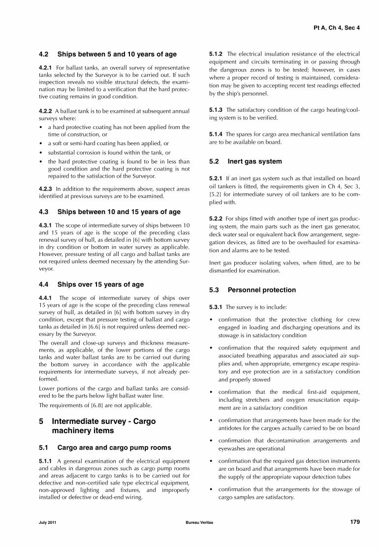
Pt A, Ch 4, Sec 4
4.2 Ships between 5 and 10 years of age
4.2.1 For ballast tanks, an overall survey of representativetanks selected by the Surveyor is to be carried out. If suchinspection reveals no visible structural defects, the exami-nation may be limited to a verification that the hard protec-tive coating remains in good condition.
4.2.2 A ballast tank is to be examined at subsequent annualsurveys where:
• a hard protective coating has not been applied from thetime of construction, or
• a soft or semi-hard coating has been applied, or
• substantial corrosion is found within the tank, or
• the hard protective coating is found to be in less thangood condition and the hard protective coating is notrepaired to the satisfaction of the Surveyor.
4.2.3 In addition to the requirements above, suspect areasidentified at previous surveys are to be examined.
4.3 Ships between 10 and 15 years of age
4.3.1 The scope of intermediate survey of ships between 10and 15 years of age is the scope of the preceding classrenewal survey of hull, as detailed in [6] with bottom surveyin dry condition or bottom in water survey as applicable.However, pressure testing of all cargo and ballast tanks arenot required unless deemed necessary by the attending Sur-veyor.
4.4 Ships over 15 years of age
4.4.1 The scope of intermediate survey of ships over15 years of age is the scope of the preceding class renewalsurvey of hull, as detailed in [6] with bottom survey in drycondition, except that pressure testing of ballast and cargotanks as detailed in [6.6] is not required unless deemed nec-essary by the Surveyor.
The overall and close-up surveys and thickness measure-ments, as applicable, of the lower portions of the cargotanks and water ballast tanks are to be carried out duringthe bottom survey in accordance with the applicablerequirements for intermediate surveys, if not already per-formed.
Lower portions of the cargo and ballast tanks are consid-ered to be the parts below light ballast water line.
The requirements of [6.8] are not applicable.
5 Intermediate survey - Cargo machinery items
5.1 Cargo area and cargo pump rooms
5.1.1 A general examination of the electrical equipmentand cables in dangerous zones such as cargo pump roomsand areas adjacent to cargo tanks is to be carried out fordefective and non-certified safe type electrical equipment,non-approved lighting and fixtures, and improperlyinstalled or defective or dead-end wiring.
5.1.2 The electrical insulation resistance of the electricalequipment and circuits terminating in or passing throughthe dangerous zones is to be tested; however, in caseswhere a proper record of testing is maintained, considera-tion may be given to accepting recent test readings effectedby the ship’s personnel.
5.1.3 The satisfactory condition of the cargo heating/cool-ing system is to be verified.
5.1.4 The spares for cargo area mechanical ventilation fansare to be available on board.
5.2 Inert gas system
5.2.1 If an inert gas system such as that installed on boardoil tankers is fitted, the requirements given in Ch 4, Sec 3,[5.2] for intermediate survey of oil tankers are to be com-plied with.
5.2.2 For ships fitted with another type of inert gas produc-ing system, the main parts such as the inert gas generator,deck water seal or equivalent back flow arrangement, segre-gation devices, as fitted are to be overhauled for examina-tion and alarms are to be tested.
Inert gas producer isolating valves, when fitted, are to bedismantled for examination.
5.3 Personnel protection
5.3.1 The survey is to include:
• confirmation that the protective clothing for crewengaged in loading and discharging operations and itsstowage is in satisfactory condition
• confirmation that the required safety equipment andassociated breathing apparatus and associated air sup-plies and, when appropriate, emergency escape respira-tory and eye protection are in a satisfactory conditionand properly stowed
• confirmation that the medical first-aid equipment,including stretchers and oxygen resuscitation equip-ment are in a satisfactory condition
• confirmation that arrangements have been made for theantidotes for the cargoes actually carried to be on board
• confirmation that decontamination arrangements andeyewashes are operational
• confirmation that the required gas detection instrumentsare on board and that arrangements have been made forthe supply of the appropriate vapour detection tubes
• confirmation that the arrangements for the stowage ofcargo samples are satisfactory.
July 2011 Bureau Veritas 179

Pt A, Ch 4, Sec 4
6 Class renewal survey - Hull items
6.1 Survey program and preparation for survey
6.1.1 The Owner in cooperation with Society is to work outa specific Survey Programme prior to the commencement ofany part of:• the class renewal survey• the intermediate survey for chemical tankers over
10 years of age.
The survey programme is to be in a written format.
Prior to the development of the survey programme, the sur-vey planning questionnaire is to be completed by theOwner, and forwarded to the Society.
The survey programme at intermediate survey may consistof the survey programme at the previous class renewal sur-vey supplemented by the hull condition evaluation report ofthat class renewal survey and later relevant survey reports.
The survey program is to be worked out taking into accountany amendments to the survey requirements after the lastclass renewal survey carried out.
6.1.2 In developing the Survey Programme, the followingdocumentation is to be collected and consulted with a viewto selecting tanks, areas, and structural elements to beexamined:
a) survey status and basic ship information
b) documentation on board, as described in [1.2.2] and[1.2.3]
c) main structural plans of cargo and ballast tanks (scant-ling drawings), including information on use of high ten-sile steels (HTS), clad steel and stainless steel
d) hull condition evaluation report
e) relevant previous damage and repair history
f) relevant previous survey and inspection reports fromboth the Society and the Owner
g) information regarding the use of the ship's tanks, typicalcargoes and other relevant data
h) details of the inert gas plant and tank cleaning proce-dures
i) information and other relevant data regarding conver-sion or modification of the ship's cargo and ballast tankssince the time of construction
j) description and history of the coating and the corrosionprevention system (previous class notations), if any
k) inspections by the Owner's personnel during the lastthree years with reference to structural deterioration ingeneral, leakages in tank boundaries and piping andcondition of the coating and corrosion prevention sys-tem, if any
l) information regarding the relevant maintenance levelduring operation including port state control reports ofinspection containing hull related deficiencies, SafetyManagement System non-conformities relating to hullmaintenance, including the associated correctiveaction(s); and
m) any other information that will help identify suspectareas and critical structural areas.
6.1.3 The submitted Survey Programme is to account forand comply, as a minimum, with the requirements forclose-up surveys, thickness measurements, tank testing andpipe testing given in Tab 1, Tab 2, [6.6] and [6.7.3], respec-tively and is to include relevant information including atleast:
a) basic ship information and particulars
b) main structural plans (scantling drawings), includinginformation on the use of high tensile steels (HTS), cladsteel and stainless steel
c) plan of tanks
d) list of tanks with information on their use, corrosion pre-vention and condition of coating
e) conditions for survey (e.g., information regarding tankcleaning, gas freeing, ventilation, lighting, etc.)
f) provisions and methods for access to structures
g) equipment for surveys
h) nomination of tanks and areas for close-up surveysaccording to [6.4]
i) nomination of sections and areas for thickness measure-ments according to [6.5]
j) nomination of tanks for tank testing according to [6.6],and the pipes that are to undergo pipe testing accordingto [6.7.3]
k) identification of the thickness measurement company
l) damage experience related to the ship in question.
m) critical structural areas and suspect areas, where rele-vant.
6.1.4 The survey program is also to include the maximumacceptable structural corrosion diminution levels applicableto the ship. The Society will advise the Owner of this infor-mation.
6.2 Survey planning meeting
6.2.1 Proper preparation and close co-operation betweenthe attending surveyor(s) and the Owner's representativesonboard prior to and during the survey are an essential partin the safe and efficient conduct of the survey. During thesurvey on board safety meetings are to be held regularly.
6.2.2 Prior to the commencement of any part of the ClassRenewal and Intermediate Survey a survey planning meet-ing is to be held between the attending Surveyor(s), theOwner's Representative in attendance and the Thicknessmeasurement company representative, where involved, andthe master of the ship or an appropriately qualified repre-sentative appointed by the master or Company for the pur-pose of ascertaining that all the arrangements envisaged inthe survey programme are in place, so as to ensure the safeand efficient conduct of the survey work to be carried out.See also Ch 2, Sec 2, [2.3.2].
180 Bureau Veritas July 2011
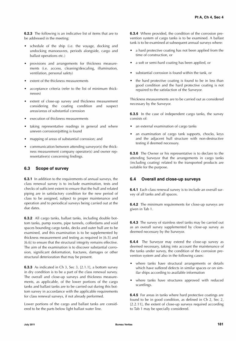
Pt A, Ch 4, Sec 4
6.2.3 The following is an indicative list of items that are tobe addressed in the meeting:
• schedule of the ship (i.e. the voyage, docking andundocking manoeuvres, periods alongside, cargo andballast operations etc.)
• provisions and arrangements for thickness measure-ments (i.e. access, cleaning/descaling, illumination,ventilation, personal safety)
• extent of the thickness measurements
• acceptance criteria (refer to the list of minimum thick-nesses)
• extent of close-up survey and thickness measurementconsidering the coating condition and suspectareas/areas of substantial corrosion
• execution of thickness measurements
• taking representative readings in general and whereuneven corrosion/pitting is found
• mapping of areas of substantial corrosion; and
• communication between attending surveyor(s) the thick-ness measurement company operator(s) and owner rep-resentative(s) concerning findings.
6.3 Scope of survey
6.3.1 In addition to the requirements of annual surveys, theclass renewal survey is to include examination, tests andchecks of sufficient extent to ensure that the hull and relatedpiping are in satisfactory condition for the new period ofclass to be assigned, subject to proper maintenance andoperation and to periodical surveys being carried out at thedue dates.
6.3.2 All cargo tanks, ballast tanks, including double bot-tom tanks, pump rooms, pipe tunnels, cofferdams and voidspaces bounding cargo tanks, decks and outer hull are to beexamined, and this examination is to be supplemented bythickness measurement and testing as required in [6.5] and[6.6] to ensure that the structural integrity remains effective.The aim of the examination is to discover substantial corro-sion, significant deformation, fractures, damages or otherstructural deterioration that may be present.
6.3.3 As indicated in Ch 3, Sec 3, [2.1.1], a bottom surveyin dry condition is to be a part of the class renewal survey.The overall and close-up surveys and thickness measure-ments, as applicable, of the lower portions of the cargotanks and ballast tanks are to be carried out during this bot-tom survey in accordance with the applicable requirementsfor class renewal surveys, if not already performed.
Lower portions of the cargo and ballast tanks are consid-ered to be the parts below light ballast water line.
6.3.4 Where provided, the condition of the corrosion pre-vention system of cargo tanks is to be examined. A ballasttank is to be examined at subsequent annual surveys where:
• a hard protective coating has not been applied from thetime of construction, or
• a soft or semi-hard coating has been applied, or
• substantial corrosion is found within the tank, or
• the hard protective coating is found to be in less thangood condition and the hard protective coating is notrepaired to the satisfaction of the Surveyor.
Thickness measurements are to be carried out as considerednecessary by the Surveyor.
6.3.5 In the case of independent cargo tanks, the surveyconsists of:
• an external examination of cargo tanks
• an examination of cargo tank supports, chocks, keysand the adjacent hull structure with non-destructivetesting if deemed necessary.
6.3.6 The Owner or his representative is to declare to theattending Surveyor that the arrangements in cargo tanks(including coating) related to the transported products aresuitable for the purpose.
6.4 Overall and close-up surveys
6.4.1 Each class renewal survey is to include an overall sur-vey of all tanks and all spaces.
6.4.2 The minimum requirements for close-up surveys aregiven in Tab 1.
6.4.3 The survey of stainless steel tanks may be carried outas an overall survey supplemented by close-up survey asdeemed necessary by the Surveyor.
6.4.4 The Surveyor may extend the close-up survey asdeemed necessary, taking into account the maintenance ofthe tanks under survey, the condition of the corrosion pre-vention system and also in the following cases:
• where tanks have structural arrangements or detailswhich have suffered defects in similar spaces or on sim-ilar ships according to available information
• where tanks have structures approved with reducedscantlings.
6.4.5 For areas in tanks where hard protective coatings arefound to be in good condition, as defined in Ch 2, Sec 2,[2.2.11], the extent of close-up surveys required accordingto Tab 1 may be specially considered.
July 2011 Bureau Veritas 181

Pt A, Ch 4, Sec 4
Table 1 : Requirements for close-up survey at class renewal survey of chemical tankers
6.5 Thickness measurements
6.5.1 The minimum requirements for thickness measure-ments at class renewal survey are given in Tab 2. Thicknessmeasurement of stainless steel hull structure and pipingmay be waived, except for clad steel plating.
6.5.2 Provisions for extended measurements for areas withsubstantial corrosion are given in Tab 3 and as may be addi-tionally specified in the survey program as required in [6.1].These extended thickness measurements are to be carriedout before the survey is credited as completed.
Suspect areas identified at previous class renewal surveysare to be examined.
Areas of substantial corrosion identified at previous surveysare to have thickness measurements taken.
The Surveyor may further extend the thickness measure-ments as deemed necessary.
6.5.3 When pitting is found on bottom plating and itsintensity is 20% or more, thickness measurements are to beextended in order to determine the actual plate thicknessout of the pits and the depth of the pits. Where the wastageis in the substantial corrosion range or the average depth ofpitting is 1/3 or more of the actual plate thickness, the pittedplate is to be considered as a substantially corroded area.
6.5.4 For areas in tanks where hard protective coatings arefound to be in good condition, the extent of thickness meas-urements according to Tab 2 may be specially consideredby the Society.
Age of ship (in years at time of class renewal survey)
age ≤ 5 5 < age ≤ 10 10 < age ≤15 age > 15
One web frame �, in a ballastwing tank (for S.H.) or a ballastdouble hull tank (for D.H.) (1)
All web frames �, in a ballast wingtank or a ballast double hull tank(1)
All web frames �: - in all ballast tanks- in a cargo wing tankOne web frame in eachremaining cargo tank �
As class renewal survey forships between 10 and 15years of age
One deck transverse �, in acargo tank or on deck
One deck transverse �:- in each remaining ballast tank
or on deck (for S.H)- in a cargo wing tank or on deck
(for S.H)- in two cargo centre tanks or on
deck (for S.H.) and one decktransverse in two cargo tanks(for D.H)
The knuckle area and the upper part(3 meters approximately) of oneweb frame in each remaining bal-last tank (for D.H.) �
Additional transverse areasas deemed necessary bythe Society
One transverse bulkhead � in aballast tank (for D.H.)
Both transverse bulkheads � in aballast wing tank (for S.H.) One transverse bulkhead � in eachballast tank (for D.H.) (1)
All transverse bulkheads �, inall cargo and ballast tanks
One transverse bulkhead �:- in a ballast tank (for S.H)- in a cargo wing tank- in a cargo centre tank (2)
One transverse bulkhead �- in each remaining ballast tank
(for S.H)- in a cargo wing tank- in two cargo centre tanks (2)
S.H. means “single hull”; D.H. means “double hull”� : Complete transverse web frame ring including adjacent structural members.� : Deck transverse including adjacent deck structural members.� : Transverse bulkhead complete, including girder system and adjacent structural members.� : Transverse bulkhead lower part, including girder system and adjacent structural members.(1) Double hull tank includes double bottom and side tank even if these tanks are separate.(2) Where no centre cargo tanks are fitted (as in the case of centre longitudinal bulkhead), transverse bulkheads in wing tanks are
to be surveyed.
182 Bureau Veritas July 2011
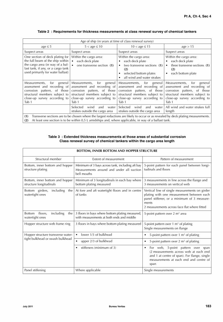
Pt A, Ch 4, Sec 4
Table 2 : Requirements for thickness measurements at class renewal survey of chemical tankers
Table 3 : Extended thickness measurements at those areas of substantial corrosionClass renewal survey of chemical tankers within the cargo area length
Age of ship (in years at time of class renewal survey)
age ≤ 5 5 < age ≤ 10 10 < age ≤ 15 age > 15
Suspect areas Suspect areas Suspect areas Suspect areas
One section of deck plating forthe full beam of the ship withinthe cargo area (in way of a bal-last tank, if any, or a cargo tankused primarily for water ballast)
Within the cargo area: • each deck plate• one transverse section (1)
Within the cargo area:• each deck plate • two transverse sections (1)
(2) • selected bottom plates• all wind and water strakes
Within the cargo area: • each deck plate • three transverse sections (1)
(2)• each bottom plate
Measurements, for generalassessment and recording ofcorrosion pattern, of thosestructural members subject toclose-up survey according toTab 1
Measurements, for generalassessment and recording ofcorrosion pattern, of thosestructural members subject toclose-up survey according toTab 1
Measurements, for generalassessment and recording ofcorrosion pattern, of thosestructural members subject toclose-up survey according toTab 1
Measurements, for generalassessment and recording ofcorrosion pattern, of thosestructural members subject toclose-up survey according toTab 1
Selected wind and waterstrakes outside the cargo area
Selected wind and waterstrakes outside the cargo area
All wind and water strakes fulllength
(1) Transverse sections are to be chosen where the largest reductions are likely to occur or as revealed by deck plating measurements.(2) At least one section is to be within 0,5 L amidships and, where applicable, in way of a ballast tank.
BOTTOM, INNER BOTTOM AND HOPPER STRUCTURE
Structural member Extent of measurement Pattern of measurement
Bottom, inner bottom and hopperstructure plating
Minimum of 3 bays across tank, including aft bayMeasurements around and under all suctionbell mouths
5-point pattern for each panel between longi-tudinals and floors
Bottom, inner bottom and hopperstructure longitudinals
Minimum of 3 longitudinals in each bay wherebottom plating measured
3 measurements in line across the flange and3 measurements on vertical web
Bottom girders, including thewatertight ones
At fore and aft watertight floors and in centreof tanks
Vertical line of single measurements on girderplating with one measurement between eachpanel stiffener, or a minimum of 3 measure-ments2 measurements across face flat where fitted
Bottom floors, including thewatertight ones
3 floors in bays where bottom plating measured,with measurements at both ends and middle
5-point pattern over 2 m2 area
Hopper structure web frame ring 3 floors in bays where bottom plating measured 5-point pattern over 1 m2 of platingSingle measurements on flange
Hopper structure transverse water-tight bulkhead or swash bulkhead
• lower 1/3 of bulkhead • 5-point pattern over 1 m2 of plating
• upper 2/3 of bulkhead • 5-point pattern over 2 m2 of plating
• stiffeners (minimum of 3) • For web, 5-point pattern over span(2 measurements across web at each endand 1 at centre of span). For flange, singlemeasurements at each end and centre ofspan
Panel stiffening Where applicable Single measurements
July 2011 Bureau Veritas 183

Pt A, Ch 4, Sec 4
DECK STRUCTURE
Structural member Extent of measurement Pattern of measurement
Deck plating 2 transverse bands across tank Minimum of 3 measurements per plate per band
Deck longitudinals Every third longitudinal in each of 2 bandswith a minimum of one longitudinal
3 measurements in line vertically on webs and2 measurements on flange (if fitted)
Deck girders and brackets At fore and aft transverse bulkhead, brackettoes and in centre of tanks
Vertical line of single measurements on webplating with one measurement between eachpanel stiffener, or a minimum of 3 measure-ments2 measurements across flange5-point pattern on girder/bulkhead brackets
Deck transverse webs Minimum of 2 webs, with measurements atboth ends and middle of span
5-point pattern over 1 m2 areaSingle measurements on flange
Vertical web and transverse bulk-head in wing ballast tank for doublehull design (2 metres from deck)
Minimum of 2 webs, and both transverse bulk-heads
5-point pattern over 1 m2 area
Panel stiffening Where applicable Single measurements
SIDE SHELL AND LONGITUDINAL BULKHEADS
Structural member Extent of measurement Pattern of measurement
Side shell and longitudinal bulk-head plating:
• deckhead and bottom strakes and strakes in way of the hori-zontal girders
• Plating between each pair of longitudinals in a minimum of 3 bays (along the tank)
Single measurement
• all other strakes • Plating between every third pair of longitu-dinals in same 3 bays
Side shell and longitudinal bulk-head longitudinals on:
• deckhead and bottom strakes • Each longitudinal in same 3 bays 3 measurements across web and 1 measure-ment on flange
• all other strakes • Every third longitudinal in same 3 bays
Longitudinals - brackets Minimum of 3 at top, middle and bottom oftank in same 3 bays
5-point pattern over area of bracket
Vertical web and transverse bulk-heads of double side tanks(excluding deck area):
• strakes in way of horizontalgirders
• Minimum of 2 webs and both transverse bulkheads
• 5-point pattern over approximately 2 m2 area
• other strakes • Minimum of 2 webs and both transverse bulkheads
• 2 measurements between each pair of ver-tical stiffeners
Web frames and cross ties forother tanks than double side tanks
3 webs with minimum of 3 locations on eachweb, including in way of cross tie connectionsand lower end bracket
5-point pattern over approximately 2 m2 areaof webs, plus single measurements on flangesof web frame and cross ties
Horizontal girders Plating on each girder in a minimum of 3 bays 2 measurements between each pair of longitu-dinal girder stiffeners
Panel stiffening Where applicable Single measurements
184 Bureau Veritas July 2011

Pt A, Ch 4, Sec 4
6.6 Tank testing
6.6.1 The requirements for tank testing at class renewal sur-vey are given in Tab 4. Pressure testing of cargo tanks maybe accepted based on confirmation from the Master statingthat the pressure testing has been carried out according tothe requirements with a satisfactory result.
Table 4 : Requirements for tank testingat class renewal survey of chemical tankers
6.6.2 The Surveyor may extend the tank testing as deemednecessary.
6.6.3 Boundaries of ballast tanks are to be tested with ahead of liquid to the top of air pipes.
Boundaries of cargo tanks are to be tested to the highestpoint that liquid will rise under service conditions.
The testing of double bottom tanks and other spaces notdesigned for the carriage of liquid may be omitted, provideda satisfactory internal examination together with an exami-nation of the tank top is carried out.
6.7 Cargo piping, cargo pump rooms and cargo tanks
6.7.1 Cargo piping on deck and cargo and ballast pipingwithin the tanks specified in [6.3.2] are to be examined andoperationally tested to working pressure to attending Sur-veyor’s satisfaction to ensure that tightness and conditionremain satisfactory. Special attention is to be given to anyballast piping in cargo tanks and cargo piping in ballasttanks and void spaces. Surveyors are to be advised on alloccasions when this piping, including valves and fittings, isopened during repair periods and can be examined inter-nally.
The Surveyor may require dismantling and/or thicknessmeasurements of piping. A hydraulic test is to be carried outin the event of repair or dismantling of cargo or ballast pip-ing, or where doubts arise.
Vent line drainage arrangements are to be examined.
6.7.2 It is to be verified that cargo piping and independentcargo tanks, where applicable, are electrically bonded tothe hull.
6.7.3 For ships over 10 years of age, selected steel cargopipes outside cargo tanks, cargo/slop discharge pipes pass-ing through ballast tanks and void spaces and ballast pipespassing through cargo tanks are to be:
• subjected to thickness measurement at random, orselected pipe lengths are to be opened for internalinspection
• pressure tested to the maximum working pressure.
TRANSVERSE WATERTIGHT AND SWASH BULKHEADS
Structural member Extent of measurement Pattern of measurement
Upper and lower stool, where fit-ted
• Transverse band within 25 mm of weldedconnection to inner bottom/deck plating
• Transverse band within 25 mm of weldedconnection to shelf plate
5-point pattern between stiffeners over 1 mlength
Deckhead and bottom strakes, andstrakes in way of horizontal stringers
Plating between pair of stiffeners at 3 locations:approximately 1/4, 1/2 and 3/4 width of tank
5-point pattern between stiffeners over 1 mlength
All other strakes Plating between pair of stiffeners at middlelocation
Single measurement
Strakes in corrugated bulkheads Plating for each change of scantling at centreof panel and at flange of fabricated connection
5-point pattern over about 1 m2 of plating
Stiffeners Minimum of 3 typical stiffeners For web, 5-point pattern over span betweenbracket connections (2 measurements acrossweb at each bracket connection and 1 at cen-tre of span). For flange, single measurements ateach bracket toe and at centre of span
Brackets Minimum of 3 at top, middle and bottom of tank 5-point pattern over area of bracket
Horizontal stringers All stringers with measurements at both endsand middle
5-point pattern over 1 m2 area, plus singlemeasurements near bracket toes and on flanges
Deep webs and girders Measurements at toe of bracket and at centre of span
For web, 5 point pattern over about 1 m2.3 measurements across face flat
Age of ship (in years at time of class renewal survey)
age ≤ 5 age >5
All ballast tank boundaries All ballast tank boundaries
Cargo tank boundaries facingballast tanks, void spaces, pipetunnels, pump rooms or coffer-dams
All cargo tank bulkheads
July 2011 Bureau Veritas 185

Pt A, Ch 4, Sec 4
6.7.4 All safety valves on cargo piping and of cargo tanksare to be dismantled for examination, adjusted and, asapplicable, resealed.
6.7.5 All cargo pump room boundaries are to be generallyexamined. All gas-tight shaft sealing devices are to beexamined. The bottom of cargo pump rooms is to be pre-sented clean for the examination of stripping devices andgutters.
6.8 Emergency towing arrangement
6.8.1 The survey is to include:• an examination of the emergency towing arrangement• confirmation that the arrangement is readily available
with aft towing arrangement pre-rigged and forwardchafing gear secured to the strong-point
• an examination of the pick-up gear, towing pennant andchafing gear over the full length for possible deteriora-tion. Where the pennant line is stored in a watertightcondition and can be confirmed as being maintained,consideration may be given to waiving the requirementto examine the pennant line over the full length
• an examination of the strong-points, fairleads and ped-estal roller together with their attachments to the hullstructure.
7 Class renewal survey - Cargo machinery items
7.1 Cargo area and cargo pump rooms
7.1.1 Ballast and stripping pumps are to be internallyexamined and prime movers checked. A working test is tobe carried out.Maintenance records of cargo pumps are to be made availa-ble to the Surveyor.
7.1.2 Where a washing system is fitted, piping, pumps,valves and deck-mounted washing machines are to beexamined and tested for signs of leakage, and anchoringdevices of deck-mounted washing machines are to bechecked to the Surveyor's satisfaction.
7.1.3 The satisfactory condition of the cargo heating/cool-ing system is to be verified and, if deemed necessary by theSurveyor, the system is to be pressure tested.
7.1.4 Spares for cargo area mechanical ventilation fans areto be available on board.
7.1.5 Heat exchangers and anti-sparking fans are to beexamined.
7.1.6 An operating test of the remote control of pumps andvalves and of automatic closing valves is to be carried out.
7.1.7 A general examination of the electrical equipmentand cables in dangerous zones such as cargo pump roomsand areas adjacent to cargo tanks is to be carried out fordefective and non-certified safe type electrical equipment,non-approved lighting and fixtures, and improperlyinstalled or defective or dead-end wiring.
The electrical insulation resistance of the electrical equip-ment and circuits terminating in or passing through the dan-gerous zones is to be tested; however, in cases where aproper record of testing is maintained, consideration maybe given to accepting recent test readings effected by theship’s personnel.
7.2 Fire-fighting systems in cargo area
7.2.1 The survey is to include the examination of fire-fight-ing systems of any type fitted on board for the protection ofthe cargo area, cargo pump room and other dangerousspaces, such as deck foam, water-spraying and dry powdersystems, as applicable in accordance with the relevantrequirements given in Ch 3, Sec 3, [3.8].
7.3 Inert gas system
7.3.1 The requirements given in [5.2] for intermediate sur-vey are to be complied with.
7.3.2 If an inert gas system such as that installed on boardoil tankers is fitted, the requirements given in Ch 4, Sec 3,[7.3] for class renewal survey of oil tankers are to be com-plied with.
7.4 Personnel protection
7.4.1 The requirements given in [5.3] are to be compliedwith.
186 Bureau Veritas July 2011
Pt A, Ch 4, Sec 5
SECTION 5 LIQUEFIED GAS CARRIERS
1 General
1.1 Application
1.1.1 The requirements of this Section apply after construc-tion to all self-propelled ships which have been assignedone of the following service notations:
• liquefied gas carrier
• liquefied gas carrier RV
• liquefied gas carrier RV STL-SPM.
1.1.2 The requirements apply to:
• the surveys of installations and equipments related tothe carriage and handling of liquefied and revaporisedgas when applicable, and
• the surveys of hull structure and related piping systemsin way of cargo tanks, pump rooms, compressor rooms,cofferdams, pipe tunnels, void spaces and fuel oil tankswithin the cargo area, and
• the surveys of all ballast tanks, and
• when fitted: revaporisation area and area of equipmentfor non permanent mooring, and for unloading to singlebuoy.
They are additional to the requirements applicable to theremainder of the ship, given in Part A, Chapter 3, accordingto the relevant surveys.
1.1.3 The requirements contain the minimum extent ofexamination, thickness measurements and tank testing.When substantial corrosion, as defined in Ch 2, Sec 2,[2.2.7], and/or structural defects are found, the survey is tobe extended and is to include additional close-up surveyswhen necessary.
1.1.4 Thickness measurements of structures in areas whereclose-up surveys are required are to be carried out simulta-neously with close-up surveys.
1.1.5 When, in any survey, thickness measurements arerequired:
• the procedure detailed in Ch 2, Sec 2, [2.3] is to beapplied
• the thickness measurement operator is to attend the sur-vey planning meeting held prior to commencing thesurvey.
2 Annual survey - Hull items
2.1 General
2.1.1 The annual survey of cargo containment and cargohandling systems is preferably carried out during loading orunloading operations. Access to cargo tanks and/or inertedhold spaces is normally not required.
2.1.2 Gas plant operational record (log) entries since thelast survey are to be examined in order to check the pastperformance of the system and to establish whether certainparts have shown any irregularities in operation. The boil-off rate, the hours per day of the reliquefaction plants andthe inert gas consumption are also to be considered.
2.1.3 The relevant instruction and information materialsuch as cargo handling plans, filling limit information, cool-ing down procedures, are to be verified as being onboard.
2.1.4 Examination of the condition of all piping systems,except those covered by [2.3].Note 1: For survey of air pipes, flame screens on vents and ventila-tors, refer to Ch 3, Sec 1, [2.1.1].
2.2 Weather decks and suspect areas
2.2.1 Examination of flame screens on vents to all bunkertanks.
2.2.2 Examination of bunker and vent piping systems.
2.2.3 Suspect areas identified at previous surveys are to beexamined. Thickness measurements are to be taken of theareas of substantial corrosion and the extent of thicknessmeasurements is to be increased to determine the extent ofareas of substantial corrosion, as per the requirements ofTab 4. These extended thickness measurements are to be carriedout before the annual survey is credited as completed.
2.3 Cargo handling rooms and piping
2.3.1 The survey is to include:• examination of cargo pump rooms, compressor rooms
and cargo control rooms and, as far as practicable, pipetunnels if fitted
• examination of all pump room and compressor roombulkheads for signs of leakage or fractures and, in par-ticular, the sealing arrangements of all penetrations ofpump room and compressor room bulkheads
• examination of all accessible gas-tight bulkhead pene-trations including gas-tight shaft sealings
• examination of the sealing arrangements for tanks ortank domes penetrating decks or tank covers
July 2011 Bureau Veritas 187
Pt A, Ch 4, Sec 5
• examination of the means for accomplishing gas tight-ness of the wheelhouse doors and windows. All win-dows and sidescuttles within the area required to be ofthe fixed type (non-opening) are to be examined for gastightness. The closing devices for all air intakes andopenings into accommodation spaces, service spaces,machinery spaces, control stations and approved open-ings in superstructures and deckhouses facing the cargoarea or bow and stern loading/unloading arrangements,are to be examined
• examination of cargo and process piping, including theexpansion arrangements, insulation from the hull struc-ture, pressure relief and drainage arrangements
• examination of venting systems, including vent mastsand protective screens, for cargo tanks, interbarrierspaces, hold spaces, fuel tanks and ballast tanks
• examination of cargo tank and interbarrier space reliefvalves and associated safety systems and alarms
• confirmation that the certificate for the relief valveopening/closing pressures is on board and that the cargotank relief valves are sealed
• examination of drip trays or insulation for deck protec-tion against cargo leakage
• confirmation of proper maintenance of arrangements forthe airlocks
• confirmation that all accessible cargo piping systems areelectrically bonded to the hull
• visual examination of arrangements for burning meth-ane boil-off as far as practicable.
2.4 Other arrangements or devices
2.4.1 The survey is to include:
• confirmation that any liquid and vapour hoses are suita-ble for their intended purpose and in satisfactory condi-tion and, where appropriate, type-approved or markedwith date of testing
• confirmation that any special arrangement made forbow or stern loading/unloading is satisfactory
• confirmation that, if applicable, the provisions made forproducts which have special arrangements as per Pt D,Ch 9, Sec 17 are satisfactory.
2.5 Ballast tanks
2.5.1 Ballast tanks are to be internally examined whenrequired as a consequence of the results of the classrenewal survey or the intermediate survey; see [6.3.7] andfootnote (3) of Tab 1, respectively.
2.5.2 When considered necessary by the Surveyor, orwhere extensive corrosion exists, thickness measurement isto be carried out. If the results of these thickness measure-ments indicate that substantial corrosion is found, then theextent of thickness measurements are to be increased todetermine the extent of areas of substantial corrosion inaccordance with the requirements given in Tab 4. Theseextended thickness measurements are to be carried outbefore the annual survey is credited as completed.
2.6 Emergency towing arrangement
2.6.1 The Owner or his representative is to declare to theattending Surveyor that no significant alterations have beenmade, without prior approval from the Society, to the equip-ment and arrangements fitted on board in accordance withthe provisions given in Pt B, Ch 10, Sec 4, [4].
2.6.2 The survey is to include:
• an examination, as far as practicable, of the emergencytowing arrangement
• confirmation that the aft towing arrangement is pre-rigged and forward chafing gear is secured to the strong-point
• confirmation of the proper functioning of the light,where it is provided, on the pick-up gear marker buoy.
3 Annual survey - Cargo machinery items
3.1 Cargo area and cargo pump rooms
3.1.1 The survey is to include:
• examination of mechanical ventilation fans in gas-dan-gerous spaces and zones
• examination and confirmation of the satisfactory opera-tion of mechanical ventilation of spaces normallyentered during operation
• examination, as far as possible during operation, ofcargo heat exchangers, vaporisers, pumps, compressorsand hoses
• confirmation that fixed and/or portable ventilationarrangements provided for spaces not normally enteredare satisfactory
• examination of the gas detection safety arrangements forcargo control rooms and of the measures taken toexclude ignition sources when such spaces are not gas-safe
• examination of cargo (if accessible), bilge, ballast andstripping pumps for excessive gland seal leakage
• confirmation that electrical equipment in gas-dangerousspaces and zones is in satisfactory condition and hasbeen properly maintained
• examination, as far as possible, of arrangements for theuse of cargo as fuel, and associated instrumentation andsafety devices.
• confirmation that, if fitted, cargo reliquefaction or refrig-eration equipment is in satisfactory condition
• confirmation that relevant instruction and informationmaterial such as cargo handling plans, filling limit infor-mation, cooling down procedures, etc., is available onboard.
188 Bureau Veritas July 2011
Pt A, Ch 4, Sec 5
3.2 Instrumentation and safety devices
3.2.1 The survey is to include:
• confirmation that installed pressure gauges on cargo dis-charge lines are operational (see [3.2.1], Note 1)
• confirmation that cargo tank liquid level gauges areoperational and that high level alarms as well as auto-matic shut-off systems are satisfactory (see [3.2.1], Note1)
• confirmation that the temperature indicating equipmentof the cargo containment system and associated alarmsare satisfactory (see [3.2.1], Note 1)
• examination of the logbooks for confirmation that theemergency shutdown system has been tested
• confirmation that cargo tank, hold and insulation spacepressure gauging systems and associated alarms are sat-isfactory (see [3.2.1], Note 1)
• examination, and testing as appropriate, of fixed gasdetection equipment
• confirmation of the availability and suitability of theportable gas detection equipment and instruments formeasuring oxygen levels
Note 1: Verification of these devices is to be done by one or moreof the following methods:
• visual external examination
• comparing of read outs from different indicators
• consideration of read outs with regard to the actual cargo and/or actual conditions
• examination of maintenance records with reference to cargoplant instrumentation maintenance manual
• verification of calibration status of the measuring instruments.
3.3 Fire-fighting systems in cargo area
3.3.1 The survey is to include the examination of fire-fight-ing systems of any type fitted on board for the protection ofthe cargo area, cargo pump room, cargo compressor roomand other dangerous spaces, such as deck foam, water-spraying and dry powder systems, as applicable in accord-ance with the relevant requirements given in Ch 3, Sec 1,[3.4].
3.4 Environmental control for cargo containment systems
3.4.1 The survey is to include:
• the examinations and tests as provided for the annualsurvey of inert gas systems of oil tankers, given in Ch 4,Sec 3, [3.4]
• confirmation that arrangements are made for sufficientinert gas to be carried to compensate for normal lossesand that means are provided for monitoring the spaces
• confirmation that the means for prevention of backflowof cargo vapour to gas-safe spaces are in satisfactoryoperating condition
• confirmation that any air drying system and any inter-barrier and hold space purging inert gas system are sat-isfactory
• for membrane containment systems normal operation ofthe nitrogen control system for insulation and interbar-rier spaces shall be confirmed to the Surveyor by theMaster.
4 Intermediate survey - Hull items
4.1 General
4.1.1 A survey planning meeting is to be held prior to thecommencement of the survey.
4.2 Weather decks, cargo handling rooms and piping
4.2.1 The survey is to include:
• examination, as far as applicable, of cargo and process,liquid nitrogen (if any), ballast, stripping and vent pipingsystems as well as vent masts and headers. If uponexamination there is any doubt as to the condition ofthe piping, pressure testing, thickness measurement orboth may be required
• examination of vent line drainage arrangements
• confirmation that cargo pipes and independent cargotanks, where applicable, are electrically bonded to thehull.
4.3 Salt water ballast tanks
4.3.1 The requirements for survey of salt water ballast tanksgiven in Tab 1 are to be complied with.
4.3.2 For ships having independent tanks of type C, with amidship section similar to that of a general cargo ship, theextent of close-up surveys may be specially considered bythe Society.
5 Intermediate survey - Cargo machinery items
5.1 General
5.1.1 The aim of the intermediate survey is to supplementthe annual survey by testing cargo handling installationswith related automatic control, alarm and safety systems forcorrect functioning.
5.1.2 The intermediate survey is preferably to be carriedout with the ship in a gas-free condition. In fact, the extentof the testing required for the intermediate survey will nor-mally be such that the survey cannot be carried out during aloading or discharging operation.
July 2011 Bureau Veritas 189

Pt A, Ch 4, Sec 5
Table 1 : Intermediate survey of salt water ballast tanks for liquefied gas carriers
5.2 Cargo area and cargo pump rooms
5.2.1 Electrical equipment and cables in dangerous zonessuch as cargo pump rooms, cargo compressor rooms andspaces adjacent to and areas above cargo tanks are to beexamined as far as practicable and tested with particularregard to:
• protective earthing (spot check)
• integrity of enclosures
• damage of outer sheath of cables
• function test of pressurised equipment and associatedalarms
• test of systems for de-energising non-certified safe elec-trical equipment located in spaces protected by air-locks, such as electric motor rooms, cargo controlrooms, etc.
5.2.2 The electrical insulation resistance of the electricalequipment and circuits in dangerous zones is to be meas-ured. These measurements are only to be effected when theship is in a gas-free or inerted condition. Where a properrecord of testing is maintained, consideration may be givento accepting recent readings by the ship’s personnel.
5.2.3 In addition to the requirements of [5.2.1] and [5.2.2],the survey also consists of:• confirmation that the cargo heating/cooling system is in
satisfactory condition• confirmation that spares are provided for cargo area
mechanical ventilation fans• confirmation that the heating system of the hull struc-
ture is in satisfactory working condition• general examination and test of leakage detection sys-
tems in interbarrier and hold spaces.
5.3 Instrumentation and safety devices
5.3.1 The survey is to include:• examination of the installed pressure gauging systems
on cargo discharge lines, cargo tanks, holds and insula-tion spaces and associated alarms
• examination of the cargo tank liquid level gauges andhigh level alarms as well as automatic shut-off systems
• examination of the temperature indicating equipment ofthe cargo containment system and associated alarms
• test of the above-mentioned instrumentation by chang-ing pressure, level and temperature as applicable andcomparing with test instruments. Simulated tests may beaccepted for sensors which are not accessible or locatedwithin cargo tanks or inerted hold spaces. The test is toinclude alarm and safety functions
Age of ship (in years at time of intermediate survey)
5 < age ≤ 10 10 < age ≤ 15 age > 15
Overall survey of representative saltwater ballast tanks, selected by theattending SurveyorSee (1), (2) and (3)
Overall survey of all salt water ballast tanks
See (1) and (3)
Overall survey of all salt water ballasttanks
See (1) and (3)
Close-up survey of:- all web frames and both transverse bulkheads
in a representative salt water ballast tank (4)and (5)
- the upper part of one web frame in anotherrepresentative salt water ballast tank
- one transverse bulkhead in another represent-ative salt water ballast tank (5)
Close-up survey of all web frames andboth transverse bulkheads in two repre-sentative salt water ballast tanks (4) and(5)
See (6), (7) and (8) See (6), (7) and (8)
(1) If such surveys reveal no visible structural defects, the examination may be limited to a verification that the corrosion preven-tion system remains efficient.
(2) If there is no hard protective coating, soft or semi-hard coating or poor coating condition, the examination is to be extended toother ballast tanks of the same type.
(3) For ballast tanks, excluding double bottom tanks, if there is no hard protective coating, soft or semi-hard coating, or poor coat-ing condition and it is not renewed, the tanks in question are to be internally examined at annual intervals.When such conditions are found in double bottom ballast tanks, the tanks in question may be internally examined at annualintervals.
(4) Complete transverse web frame including adjacent structural members.(5) Transverse bulkhead complete, including girder system and adjacent members, and adjacent longitudinal bulkhead structure.(6) The extent of close-up surveys may be extended in accordance with the requirements of [6.4.3].(7) For areas in salt water ballast tanks where protective coating is found to be in good condition, as defined in Ch 2, Sec 2,
[2.2.11], the extent of close-up survey may be specially considered.(8) Ballast tanks include topside, double hull side, double bottom, hopper side, or any combined arrangement of the aforemen-
tioned, and peak tanks where fitted.
190 Bureau Veritas July 2011

Pt A, Ch 4, Sec 5
• examination, as far as practicable, of the piping of thegas detection system for corrosion and damage. Theintegrity of the suction lines between suction points andanalysing units is to be verified as far as possible
• calibration of gas detectors or verification thereof withsample gases
• confirmation that two sets of portable gas detectionequipment suitable for the cargoes to be carried and asuitable instrument for measuring oxygen levels are pro-vided
• test of the manually operated emergency shutdown sys-tem (without flow in the pipelines) to verify that the sys-tem will cause the cargo pumps and compressors tostop.
5.3.2 The arrangements for the use of cargo as fuel are tobe examined, when applicable. It is to be tested, as far aspracticable, that the gas supply to the machinery space iscut-off should the exhaust ventilation not be functioningcorrectly and that master gas fuel valve may be remotelyclosed from within the machinery space.
The instrumentation and safety systems for burning cargo asfuel are to be examined in accordance with [5.3.1].
5.4 Inert gas system
5.4.1 If an inert gas system such as that installed on boardoil tankers is fitted, the requirements given in Ch 4, Sec 3,[5.2] for intermediate survey of oil tankers are to be com-plied with.
5.4.2 In the case of low temperature liquid nitrogen stor-age, the plant and its associated arrangements for protectingthe hull structure against liquid nitrogen leakage are to beexamined.
5.5 Personnel protection
5.5.1 The survey is to include:
• confirmation that two complete sets of safety equipmenteach permitting personnel to enter and work in a gas-filled space are provided and properly stowed
• confirmation that the requisite supply of compressed airis provided and examination, when applicable, of thearrangements for any special air compressor and low-pressure air line system
• confirmation that the medical first-aid equipment,including stretchers and oxygen resuscitation equip-ment and antidotes, when available, for the products tobe carried are provided
• confirmation that respiratory and eye protection suitablefor emergency escape purposes are provided
• confirmation that decontamination arrangements andeyewashes are operational
• examination, when applicable, of the arrangements toprotect personnel against the effects of a major cargorelease by a special suitably designed and equippedspace within the accommodation spaces.
6 Class renewal survey - Hull items
6.1 Preparation for survey
6.1.1 The Owner is to provide the necessary facilities for asafe and practical execution of the surveys, including themeans of providing access to structures for close-up survey,thickness measurements and tank testing. All other provi-sions described in Ch 2, Sec 2, [2.3], Ch 2, Sec 2, [2.5], Ch2, Sec 2, [2.6], Ch 2, Sec 2, [2.7] and Ch 2, Sec 2, [2.8]regarding procedures for thickness measurements, condi-tions for survey, access to structures, equipment for surveyand survey at sea or at anchorage, respectively, are also tobe complied with.
6.2 Survey programme
6.2.1 A specific survey programme should be worked outin advance of the class renewal survey by the Owner incooperation with the Society.
6.2.2 The survey programme is to include conditions forsurvey, access to structures and equipment for surveys, tak-ing into account the minimum requirements of Tab 2 andTab 3 for close-up survey and thickness measurements, and[6.6] for tank testing.
6.3 Scope of survey
6.3.1 A survey planning meeting is to be held prior to thecommencement of the survey.
6.3.2 In addition to the requirements of annual surveys, theclass renewal survey is to include examination, tests andchecks of sufficient extent to ensure that the hull and relatedpiping, as required in [6.3.4], are in satisfactory conditionand fit for the intended purpose for the new period of classto be assigned, subject to proper maintenance and opera-tion and to periodical surveys being carried out at the duedates.
6.3.3 Ballast tanks, including double bottom tanks, pumprooms, compressor rooms, pipe tunnels, cofferdams andvoid spaces bounding cargo tanks, decks and outer hull areto be examined, and this examination is to be supple-mented by thickness measurement and testing as requiredin [6.5] and [6.6], to ensure that the structural integrityremains effective. The aim of the examination is to discoversubstantial corrosion, significant deformation, fractures,damages or other structural deterioration that may bepresent.
6.3.4 All piping systems within the above spaces, are to beexamined and operationally tested to working pressure toattending Surveyor's satisfaction to ensure that tightness andcondition remain satisfactory.
6.3.5 The survey extent of ballast tanks converted to voidspaces is to be specially considered in relation to therequirements for ballast tanks.Note 1: For survey of automatic air pipe heads, refer to Ch 3, Sec 3,Tab 1.
July 2011 Bureau Veritas 191
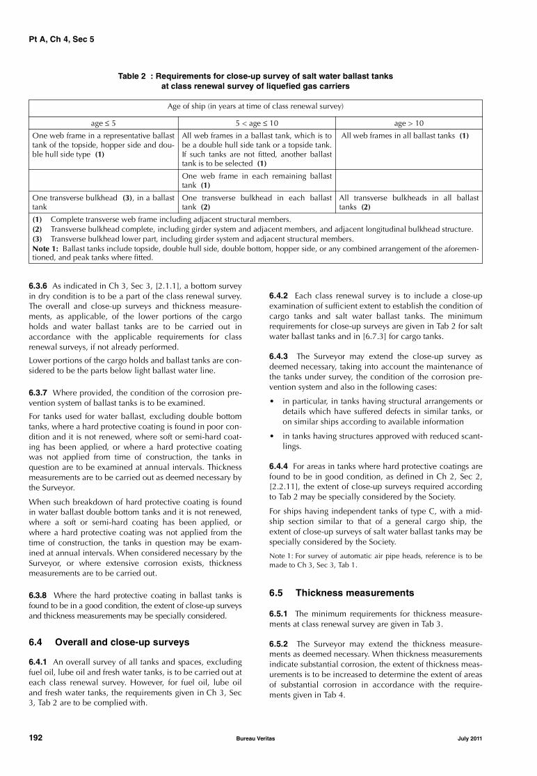
Pt A, Ch 4, Sec 5
Table 2 : Requirements for close-up survey of salt water ballast tanksat class renewal survey of liquefied gas carriers
6.3.6 As indicated in Ch 3, Sec 3, [2.1.1], a bottom surveyin dry condition is to be a part of the class renewal survey.The overall and close-up surveys and thickness measure-ments, as applicable, of the lower portions of the cargoholds and water ballast tanks are to be carried out inaccordance with the applicable requirements for classrenewal surveys, if not already performed.
Lower portions of the cargo holds and ballast tanks are con-sidered to be the parts below light ballast water line.
6.3.7 Where provided, the condition of the corrosion pre-vention system of ballast tanks is to be examined.
For tanks used for water ballast, excluding double bottomtanks, where a hard protective coating is found in poor con-dition and it is not renewed, where soft or semi-hard coat-ing has been applied, or where a hard protective coatingwas not applied from time of construction, the tanks inquestion are to be examined at annual intervals. Thicknessmeasurements are to be carried out as deemed necessary bythe Surveyor.
When such breakdown of hard protective coating is foundin water ballast double bottom tanks and it is not renewed,where a soft or semi-hard coating has been applied, orwhere a hard protective coating was not applied from thetime of construction, the tanks in question may be exam-ined at annual intervals. When considered necessary by theSurveyor, or where extensive corrosion exists, thicknessmeasurements are to be carried out.
6.3.8 Where the hard protective coating in ballast tanks isfound to be in a good condition, the extent of close-up surveysand thickness measurements may be specially considered.
6.4 Overall and close-up surveys
6.4.1 An overall survey of all tanks and spaces, excludingfuel oil, lube oil and fresh water tanks, is to be carried out ateach class renewal survey. However, for fuel oil, lube oiland fresh water tanks, the requirements given in Ch 3, Sec3, Tab 2 are to be complied with.
6.4.2 Each class renewal survey is to include a close-upexamination of sufficient extent to establish the condition ofcargo tanks and salt water ballast tanks. The minimumrequirements for close-up surveys are given in Tab 2 for saltwater ballast tanks and in [6.7.3] for cargo tanks.
6.4.3 The Surveyor may extend the close-up survey asdeemed necessary, taking into account the maintenance ofthe tanks under survey, the condition of the corrosion pre-vention system and also in the following cases:
• in particular, in tanks having structural arrangements ordetails which have suffered defects in similar tanks, oron similar ships according to available information
• in tanks having structures approved with reduced scant-lings.
6.4.4 For areas in tanks where hard protective coatings arefound to be in good condition, as defined in Ch 2, Sec 2,[2.2.11], the extent of close-up surveys required accordingto Tab 2 may be specially considered by the Society.
For ships having independent tanks of type C, with a mid-ship section similar to that of a general cargo ship, theextent of close-up surveys of salt water ballast tanks may bespecially considered by the Society.
Note 1: For survey of automatic air pipe heads, reference is to bemade to Ch 3, Sec 3, Tab 1.
6.5 Thickness measurements
6.5.1 The minimum requirements for thickness measure-ments at class renewal survey are given in Tab 3.
6.5.2 The Surveyor may extend the thickness measure-ments as deemed necessary. When thickness measurementsindicate substantial corrosion, the extent of thickness meas-urements is to be increased to determine the extent of areasof substantial corrosion in accordance with the require-ments given in Tab 4.
Age of ship (in years at time of class renewal survey)
age ≤ 5 5 < age ≤ 10 age > 10
One web frame in a representative ballasttank of the topside, hopper side and dou-ble hull side type (1)
All web frames in a ballast tank, which is tobe a double hull side tank or a topside tank.If such tanks are not fitted, another ballasttank is to be selected (1)
All web frames in all ballast tanks (1)
One web frame in each remaining ballasttank (1)
One transverse bulkhead (3), in a ballasttank
One transverse bulkhead in each ballasttank (2)
All transverse bulkheads in all ballasttanks (2)
(1) Complete transverse web frame including adjacent structural members.(2) Transverse bulkhead complete, including girder system and adjacent members, and adjacent longitudinal bulkhead structure.(3) Transverse bulkhead lower part, including girder system and adjacent structural members.Note 1: Ballast tanks include topside, double hull side, double bottom, hopper side, or any combined arrangement of the aforemen-tioned, and peak tanks where fitted.
192 Bureau Veritas July 2011

Pt A, Ch 4, Sec 5
Table 3 : Requirements for thickness measurements at class renewal survey of liquefied gas carriers
Table 4 : Requirements for extent of thickness measurements at those areas of substantial corrosion
6.5.3 For areas in tanks where hard protective coatings arefound to be in good condition as defined in Ch 2, Sec 2,[2.2.11], the extent of thickness measurements according toTab 3 may be specially considered by the Society.
6.5.4 For ships having independent tanks of type C, with amidship section similar to that of a general cargo ship, theextent of thickness measurements may be increased to thetank top plating to the satisfaction of the Surveyor.
6.5.5 Transverse sections are to be chosen where the larg-est reductions are suspected to occur or are revealed fromdeck plating measurements.
6.6 Tank testing
6.6.1 All boundaries of water ballast tanks and deep tanksused for water ballast within the cargo area are to be pres-sure tested. For fuel oil tanks, the representative tanks are tobe pressure tested.
6.6.2 The Surveyor may extend the tank testing as deemednecessary.
6.6.3 Tank testing of fuel oil tanks is to be carried out with ahead of liquid to the highest point that liquid will rise underservice conditions. Tank testing of fuel oil tanks may be spe-cially considered based on a satisfactory external examina-tion of the tank boundaries, and a confirmation from theMaster stating that the pressure testing has been carried outaccording to the requirements with satisfactory results.
6.7 Cargo tank structure
6.7.1 All cargo tanks are to be cleaned and examined inter-nally.
6.7.2 When accessible, the outer surface of uninsulatedcargo tanks or the outer surface of cargo tank insulationtogether with any vapour or protective barrier is to be exam-ined. Special attention is to be given to the tank and insula-tion in way of chocks, supports and keys. Removal ofinsulation, in part or entirely, may be required in order toverify the condition of the tank or the insulation itself ifdeemed necessary by the Surveyor.
Where the arrangement is such that the insulation cannotbe examined entirely, the surrounding structures of wingtanks, double bottom tanks and cofferdams are to be exam-ined for cold spots when the cargo tanks are in the coldcondition, unless voyage records together with the instru-mentation give sufficient evidence of the integrity of theinsulation system.
6.7.3 Thickness measurements may be required if deemednecessary by the Surveyor.
Close-up surveys are to be carried out in independent cargotanks of type B and C at those areas where corrosion maydevelop.
Age of ship (in years at time of class renewal survey)
age ≤ 5 5 < age ≤ 10 10 < age ≤ 15 age > 15
Suspect areas Suspect areas Suspect areas Suspect areas
One section of deck plating forthe full beam of the ship within0,5 L amidships in way of aballast tank, if any
Within the cargo area: • each deck plate• one transverse section
within 0,5 L amidships inway of a ballast tank, if any
Within the cargo area:• each deck plate • two transverse sections (1)• all wind and water strakes
Within the cargo area: • each deck plate • three transverse sections (1)• each bottom plate • duct keel plating and inter-
nals
Measurements, for generalassessment and recording ofcorrosion pattern, of those struc-tural members subject to close-up survey according to Tab 2
Measurements, for generalassessment and recording ofcorrosion pattern, of those struc-tural members subject to close-up survey according to Tab 2
Measurements, for generalassessment and recording ofcorrosion pattern, of those struc-tural members subject to close-up survey according to Tab 2
Measurements, for generalassessment and recording ofcorrosion pattern, of those struc-tural members subject to close-up survey according to Tab 2
Selected wind and waterstrakes outside the cargo area
Selected wind and waterstrakes outside the cargo area
All wind and water strakes fulllength
(1) at least one section is to include a ballast tank within 0,5 L amidships, if any.
Structural member Extent of measurement Pattern of measurement
Plating Suspect area and adjacent plates 5-point pattern over 1 m2 of plating
Stiffeners Suspect area 3 measurements each in line across web and flange
July 2011 Bureau Veritas 193
Pt A, Ch 4, Sec 5
6.7.4 Non-destructive testing is to supplement cargo tankinspection with special attention to be given to the integrityof the main structural members, tank shell and highlystressed parts, including welded connections as deemednecessary by the Surveyor.
However, for type C tanks, this does not mean that non-destructive testing can be dispensed with totally
The following items are, inter alia, considered highlystressed areas:
• cargo tank supports and anti-rolling or anti-pitchingdevices
• web frames or stiffening rings
• Y-connection of shell plates and longitudinal bulkheadof bilobe tanks
• swash bulkhead boundaries
• dome and stump connections to the shell plating
• foundations for pumps, towers, ladders, etc.
• pipe connections.
6.7.5 For independent tanks of type B, the extent of non-destructive testing is to be as given in a program speciallyprepared for the cargo tank design.
6.7.6 The tightness of all cargo tanks is to be verified by anappropriate procedure. Provided that the effectiveness ofthe ship's gas detection equipment has been confirmed, itwill be acceptable to utilise this equipment for the tightnesstest of independent tanks below deck.
6.7.7 Where the results of the examinations dealt with in[6.7.1] to [6.7.6] or the examination of the voyage recordsraise doubts as to the structural integrity of a cargo tank, ahydraulic or hydropneumatic test is to be carried out.
For integral tanks and for independent tanks of type A andB, the test pressure is not to be less than the MARVS.
For independent tanks of type C, the test pressure is not tobe less than 1,25 times the MARVS.
6.7.8 When the ship is 10 years old, at every alternate classrenewal survey, independent cargo tanks of type C are to beeither:
• hydraulically or hydro-pneumatically tested to1,25 times the MARVS, and thereafter non-destructivelytested in accordance with [6.7.4], or
• subjected to thorough non-destructive testing in accord-ance with a program specially prepared for the tankdesign submitted by the Owner to the Society foracceptance. If a special program of non-destructive test-ing does not exist, special attention is to be given to thedetection of surface cracks in welded connections inhighly stressed areas as listed in [6.7.4]. At least 10% ofthe length of the welded connections in each of theabove-mentioned areas is to be tested. This testing is tobe carried out internally and externally, as applicable.Insulation is to be removed as necessary for the requirednon-destructive testing.
Where hold space atmosphere control is permanently main-tained, the scope of external examination of the tanks andtheir supports may be reduced at the Surveyor's discretion.
6.7.9 As far as accessible, hold spaces and hull insulation(if provided), secondary barriers and tank supporting struc-tures are to be visually examined. The secondary barrier oftanks is to be checked for its effectiveness by means of apressure/vacuum test, a visual examination or any otheracceptable method.
6.7.10 For membrane, semi-membrane and internal insula-tion tank systems, inspection and testing are to be carriedout in accordance with programmes specially prepared inaccordance with an approved method for the actual tanksystem.
For membrane containment systems a tightness test of thesecondary barrier is to be carried out in accordance withthe system designers procedures as approved by the Society.
For membrane containment systems with glued secondarybarriers the values obtained are to be compared with previ-ous results or results obtained at newbuilding stage. If sig-nificant differences are observed for each tank or betweentanks, the Surveyor is to require an evaluation and addi-tional testing as necessary.
6.7.11 All gas-tight bulkheads are to be examined and theeffectiveness of gas-tight shaft sealing is to be verified.
6.7.12 It is to be verified that independent cargo tanks areelectrically bonded to the hull.
6.7.13 The pressure relief valves for the cargo tanks are to beopened for examination, adjusted, function tested andsealed. If the cargo tanks are equipped with relief valves withnon-metallic membranes in the main or pilot valves, thesenon-metallic membranes are to be replaced. Where a properrecord of continuous overhaul and re-testing of individuallyidentifiable relief valves is maintained, consideration may begiven to acceptance on the basis of opening, internal exami-nation and testing of a representative sample of valves,including each size and type of liquefied gas or vapour reliefvalves in use, provided there is evidence in the log-book thatthe remaining valves have been overhauled and tested sincecrediting of the previous class renewal survey.
6.8 Weather decks, cargo handling rooms and piping
6.8.1 Piping for cargo and process, liquid nitrogen (if any),ballast, stripping and venting systems is to be examined tothe Surveyor's satisfaction and opened as deemed neces-sary. Insulation is to be removed as deemed necessary toascertain the condition of the pipes. If the visual examina-tion raises doubts as to the integrity of the pipelines, a pres-sure test at 1,25 times the MARVS for the pipeline is to becarried out. After reassembly the complete piping systemsare to be tested for leaks.
It is to be verified that cargo piping systems are electricallybonded to the hull.
6.8.2 The pressure relief valves on cargo piping are to befunction tested. A random selection of valves is to beopened for examination and adjusted.
194 Bureau Veritas July 2011
Pt A, Ch 4, Sec 5
6.8.3 All cargo pump room, compressor room and controlroom boundaries are to be generally examined. Gas-tightshaft sealing devices are to be examined. The bottom ofcargo pump rooms and cargo compressor rooms is to bepresented clean for the examination of stripping devicesand gutters.
6.8.4 Pressure/vacuum relief valves, rupture discs and otherpressure relief devices for interbarrier spaces and/or holdspaces are to be examined and, if necessary, opened andtested in accordance with their design.
Vent line drainage arrangements are to be examined.
6.9 Emergency towing arrangement
6.9.1 The survey is to include:
• an examination of the emergency towing arrangement
• confirmation that the arrangement is readily availablewith aft towing arrangement pre-rigged and forwardchafing gear secured to the strong-point
• an examination of the pick-up gear, towing pennant andchafing gear over the full length for possible deteriora-tion. Where the pennant line is stored in a watertightcondition and can be confirmed as being maintained,consideration may be given to waiving the requirementto examine the pennant line over the full length
• an examination of the strong-points, fairleads and ped-estal roller together with their attachments to the hullstructure.
7 Class renewal survey - Cargo machinery items
7.1 Cargo area, cargo pump rooms, cargo compressor rooms
7.1.1 Ballast and stripping pumps are to be internallyexamined and prime movers checked. A working test is tobe carried out.
Maintenance records of cargo pumps are to be made availa-ble to the Surveyor.
7.1.2 Electrical equipment and cables in dangerous zonessuch as cargo pump rooms, cargo compressor rooms andspaces adjacent to and areas above cargo tanks are to beexamined as far as practicable and tested with particularregard to:
• protecting earthing (spot check)
• integrity of enclosures
• damage of outer sheath of cables
• function testing of pressurised equipment and associ-ated alarms
• testing of systems for de-energising non-certified safeelectrical equipment located in spaces protected by air-locks, such as electric motor rooms, cargo controlrooms, etc.
7.1.3 The electrical insulation resistance of the electricalequipment and circuits in dangerous zones is to be meas-ured. These measurements are only to be effected when theship is in a gas-free or inerted condition. Where a properrecord of testing is maintained, consideration may be givento accepting recent readings by the ship’s personnel.
7.1.4 When there is a reliquefaction or refrigeration plant,and/or arrangements for the use of cargo as fuel, the corre-sponding machinery and equipment, such as cargo pumps,compressors, heat exchangers, condensers and processpressure vessels, are to be surveyed to the same extent asrequired for similar equipment on board oil tankers at theclass renewal survey (refer to Ch 4, Sec 3).
7.1.5 In addition to the requirements of [7.1.1] to [7.1.4],the survey also consists of:
• confirmation that spares are provided for cargo areamechanical ventilation fans
• confirmation that the installation for heating the hullstructure is in satisfactory working condition
• general examination and testing of leakage detectionsystems in interbarrier spaces and hold spaces
• examination of gas detection piping system for corro-sion or damage; checking, as far as possible, of theintegrity of suction lines between suction points andanalysing units
• examination and tests of systems for the removal ofwater from interbarrier spaces and hold spaces
• examination of portable equipment, such as hoses andspool pieces used for segregation of piping systems forcargo, inert gas and bilge pumping.
7.1.6 Cargo pumps, compressors, process pressure vessels,liquid nitrogen tanks, heat exchangers and other compo-nents, including prime movers, used in connection withcargo handling and methane boil-off burning are to be sur-veyed according to the requirements of Part A, Chapter 3.
7.2 Fire-fighting systems in cargo area
7.2.1 The survey is to include the examination of fire-fight-ing systems of any type fitted on board for the protection ofthe cargo area, cargo pump room, cargo compressor roomand other dangerous spaces, such as deck foam, water-spraying, dry powder systems etc., as applicable in accord-ance with the relevant requirements given in Ch 3, Sec 3,[3.8].
7.3 Inert gas system
7.3.1 If an inert gas system such as that installed on boardoil tankers is fitted, the requirements given in Ch 4, Sec 3,[7.3] are to be complied with.
7.3.2 In the case of low temperature liquid nitrogen stor-age, the plant and its associated arrangements for protectingthe hull structure against liquid nitrogen leakage are to beexamined.
July 2011 Bureau Veritas 195
Pt A, Ch 4, Sec 5
7.4 Personnel protection
7.4.1 The requirements given in [5.5] are to be compliedwith.
8 First loaded voyage of ships carrying liquefied natural gases (LNG) in bulk
8.1
8.1.1 The survey requirements for the examination beforeand after the first loaded voyage for ships assigned with theservice notation liquefied gas carrier, carrying liquefiednatural gases (LNG) in bulk are to be carried out in accord-ance with Pt D, Ch 9, Sec 1, [4.2.4].
9 Revaporisation installation
9.1 Application
9.1.1 The requirements of this Article are applicable to self-propelled ships which have been assigned the notations:
• liquefied gas carrier RV, or
• liquefied gas carrier RV STL-SPM
These requirements apply to the revaporisation installationand to the area in way of this installation.
Reference is also made to other Articles of this Section foritems dedicated to the revaporisation installation such ascargo tanks or control stations.
9.2 Annual survey
9.2.1 General
The annual survey of the revaporisation installation is pref-erably carried out during unloading operations with thisinstallation in operation.
Revaporisation installation operational record entries(Bridge and Cargo logbooks) since the last survey are to beexamined in order to check the past performance of the sys-tem and to establish whether certain parts have shown anyirregularities in operation.
9.2.2 Equipment in contact with gas or in gas dangerous areas
The survey is to include:
a) examination of the cargo suction drum(s) and their seal-ing arrangements if applicable
b) examination of the areas dedicated to revaporisationequipments
c) examination of closing devices of air intakes and open-ings into dedicated spaces for revaporisation if applica-ble
d) examination of cargo and process piping, including theexpansion arrangements, insulation from the hull struc-ture, pressure control valves, inlet/outlet valves, drain-age arrangements and high pressure manifolds
e) examination of the relief valves, their sealing and asso-ciated safety systems and alarms
f) confirmation that the certificate for the relief valvesopening/closing pressures is on board
g) examination of high pressure pumps as far as practica-ble (including gland leakage and vibration indications)
h) external examination of vaporisers and their fittings
i) external examination of heat exchangers
j) examination of drip trays or insulation for deck protec-tion and recesses against cargo leakage in revaporisa-tion area
k) confirmation that all accessible cargo piping systemsand components (cargo suction drum(s), vaporisers,high pressure pumps) are electrically bonded to thehull.
9.2.3 Instrumentation and safety devicesThe survey is to include examination of pressure gauges,control valves, metering unit, temperature and vibrationindicating equipments. Particular attention is to be given tohigh pressure pumps instrumentation and safety devices
Confirmation that the instrumentation fitted on revaporisa-tion equipment and in contact with gas and associatedalarms are satisfactory.
Examination and testing as appropriate, of fixed gas detec-tion equipment.
Examination of the logbooks for confirmation that the auto-matic emergency shut-down system has been tested. Confir-mation that the automatic shut-down system is satisfactory.
9.2.4 Other arrangements or devicesThe survey is to include confirmation that:
• relevant shipboard instructions and procedures of therevaporisation installation are available
• the revaporisation control station is in satisfactory work-ing condition.
Water spraying system against gas leakage is to be surveyedin accordance with the relevant requirements given in Ch 3,Sec 1, [3.4].
Water deluge system is to be examined, including pipingnozzles if fitted, and distribution valves. The starting of thepump is to be tested.
9.3 Intermediate survey
9.3.1 GeneralThe aim of the intermediate survey is to supplement theannual survey by testing the revaporisation installation withrelated automatic control, alarm and safety systems for cor-rect functioning.
9.3.2 Equipment in contact with gas or in gas dangerous areas
The maintenance records of vaporisers are to be reviewed.If deemed necessary by the Surveyor, thickness measure-ments, pressure test and/or opening-up and internal exami-nation as far as practicable may be required. Particularattention is to be given to rupture device if fitted.
196 Bureau Veritas July 2011

Pt A, Ch 4, Sec 5
The survey is also to include:
a) examination, as far as applicable, of stripping and ventpiping systems and high pressure manifolds of cargoand process. If upon examination there is any doubt asto the condition of the piping, pressure testing, thicknessmeasurement or both may be required
b) examination of vent line drainage arrangements
c) confirmation that cargo pipes and revaporisation com-ponents are electrically bonded to the hull
d) random test of high pressure pumps lifting device
e) thickness measurements of cargo suction drum(s) ifdeemed necessary by the Surveyor
f) examination of electrical equipment according to [5.2].
9.3.3 Instrumentation and safety devices
The survey is to include examination of pressure gauges,control valves, metering unit, liquid level gauges, tempera-ture and vibration indicating equipments, and associatedalarms. Particular attention is to be given to high pressurepumps instrumentation and safety devices.
The above mentioned instrumentation is to be tested bychanging pressure, level and temperature as far as practica-ble and comparing with test instruments. Simulated testsmay be accepted for sensors which are not accessible. Thetest is to include alarms and safety functions.
The manually operated emergency shut-down system is tobe operationally tested to verify that the system will causethe revaporisation installation to stop.
9.3.4 Other arrangements or devices
Water deluge system is to be tested as deemed necessary bythe Surveyor.
9.4 Class renewal survey
9.4.1 General
In addition to the requirements of annual surveys, the classrenewal survey is to include examination, tests and checksof sufficient extent to ensure that the revaporisation installa-tion is in satisfactory condition for the new period of classto be assigned, subject to proper maintenance and opera-tion and to periodical surveys being carried out at the duedates.
9.4.2 Cargo suction drum
The following requirements apply:
a) Cargo suction drum(s) is (are) to be presented clean andexamined internally.
b) When accessible, the outer surface of uninsulated cargosuction drum(s) or the outer surface of unit insulationtogether with any vapour or protective barrier is to beexamined. Particular attention is to be given to the stock-ing unit and insulation in way of supports. Removal ofinsulation, in part or entirely, may be required in order toverify the condition of the unit or the insulation itself ifdeemed necessary by the Surveyor.
c) Thickness measurements or non-destructive testing maybe required if deemed necessary by the Surveyor.
d) The tightness of cargo suction drums is to be verified byan appropriate procedure.
e) Where the results of the examinations in items a) to e) orthe examination of the operational records raise doubtsas to the structural integrity of the unit, a hydraulic orhydro pneumatic test is to be carried out. The test pres-sure is not to be less than 1,25 times the MARVS.
f) When the ship is 10 years old, at every alternate classrenewal survey, cargo suction drum(s) is (are) to beeither: hydraulically tested and thereafter non-destruc-tively tested or subjected to thorough non-destructivetesting as per [6.7.8].
g) As far as accessible, the cargo suction drum(s) support-ing structures are to be visually examined.
h) Their fittings, valves and safety devices are to be openedup, as deemed necessary by the Surveyor, for visualexamination and pressure tested as appropriate.
9.4.3 Equipment in contact with gas or in gas dangerous areas
Piping for cargo and process, stripping, venting systemshigh pressure manifolds are to be examined to the Sur-veyor's satisfaction. Insulation is to be removed as deemednecessary to ascertain the condition of the pipes. If the vis-ual examination raises doubts as to the integrity of the pipe-lines, a pressure test at 1,25 times the MARVS for thepipeline is to be carried out. After reassembly the completepiping systems are to be tested for leaks.
Maintenance records and log books of high pressure pumpsincluding starting pumps are to be made available to theSurveyor. As deemed necessary by the Surveyor, the highpressure pumps are to be opened up for visual examinationand their parts and components pressure tested. The liftingdevice is to be tested.
The bottom of the high pressure pump recess and vaporiserspaces are to be presented clean for the examination of gut-ters and stripping devices.
The pressure relief valves are to be opened for examination,adjusted, function tested and sealed. The valves includinginlet/outlet valves, pressure control valves and dischargevalves are to be tested for proper operation.
The maintenance records of vaporisers are to be reviewed.The Surveyor may require as considered necessary:
• external and internal examination of vaporisers whichare to be presented clean
• opening up of their fittings, valves and safety devices forvisual examination and pressure tests
• thickness measurements and/or pressure test.
• confirmation that cargo pipes and revaporisation com-ponents are electrically bonded to the hull
Particular attention is to be taken in way of the vaporiserrupture device if fitted.
July 2011 Bureau Veritas 197
Pt A, Ch 4, Sec 5
As deemed necessary by the Surveyor, the vaporisers heatexchangers
• are to be opened up for visual examination
• their parts and components are to be pressure tested asappropriate
• A working test is also to be carried out, including testingof alarms and safety devices.
The electrical equipment are to be surveyed according to[7.1.2] and [7.1.3].
9.4.4 Instrumentation and safety devices
The survey is to include examination of pressure gauges,control valves, metering unit, liquid level gauges, tempera-ture and vibration indicating equipments, and associatedalarms. Particular attention is to be given to high pressurepumps instrumentation and safety devices.
The above mentioned instrumentation is to be tested bychanging pressure, level and temperature as applicable andcomparing with test instruments. Simulated tests may beaccepted for sensors which are not accessible. The test is toinclude alarms and safety functions.
The emergency shut-down system is to be tested.
9.4.5 Other arrangements or devices
Water spraying system against gas leakage, when fitted, areto be surveyed in accordance with the relevant require-ments given in Ch 3, Sec 3, [3.8].
For water deluge system:
• the associated pumps are to be opened up and exam-ined at the Surveyor's discretion
• a working test is to be carried out.
10 STL-SPM
10.1 Application
10.1.1 The requirements of this Article apply to self-pro-pelled ships which have been assigned the notations lique-fied gas carrier RV STL-SPM. These requirements apply tothe installation for non permanent mooring or for connec-tion to single buoy and for cargo unloading and to the areain way of this installation.
Reference is also made to above Articles of this Section foritems dedicated to the STL-SPM installation such as ventila-tion or fire fighting.
10.2 Annual survey
10.2.1 General
The Owner or his representative is to declare to the attend-ing Surveyor that no significant alterations have been madewithout the prior approval of the Society.
Operational record (log) entries since the last survey are tobe examined in order to check the past performance of theinstallation and to establish whether certain parts haveshown any irregularities in operation.
10.2.2 Piping and flexible riserThe survey is to include:
• external examination of readily accessible parts includ-ing the outer sheath and the end fittings
• examination of pipes and their connections, of accesso-ries including gas vent systems, bending restrictors,clamps and supports. Confirmation that there is noloose holding or connection
• examination of gas vent valves.
10.2.3 STL-SPM compartment, handling and connecting systems
The annual survey is to include:
• a general examination of components of the installationincluding winches, heave compensator and sheaves,rope guides, capstans, rope, hatch system, lockingmechanism, quick release unit, sealing devices, chainstoppers, fairleads, pedestal roller and covers to verifytheir satisfactory condition.
• an examination of the hull structures supporting andadjacent to the installation, to verify that no deforma-tions or fractures have developed. Particular attention isto be given to the lower part of the trunk, intermittentlyin contact with sea water.
• confirmation that emergency escape route is practicableand not blocked
• a visual examination of the lower hatch covers, the seal-ing arrangements as far as practicable, the supportingand locking devices.
10.2.4 Swivel systemThe survey is to include:
a) external examination of gas, electrical or/and hydraulicswivels with instrumentation and safety devices
b) examination of piping systems including leak drainagesystem
c) examination of connectors
d) examination of handling arm when fitted
e) tests of protective devices
f) examination of support structure.
10.2.5 OthersThe survey is to include:
a) examination of pressure gauges, control valves, temper-ature and vibration indicating equipments
b) confirmation that the instrumentation dedicated to STL-SPM and associated alarms are satisfactory
c) examination and testing as appropriate, of fixed gasdetection equipment
d) examination of the vent line drainage arrangements andthe trunk structure
e) examination of blast relief panels and verification thatthey are kept clear
f) examination of the logbooks for confirmation that theemergency and automatic shutdown systems have beentested and confirmation that they are satisfactory
198 Bureau Veritas July 2011

Pt A, Ch 4, Sec 5
10.3 Intermediate survey
10.3.1 Cargo tanks requirements originated from STL-SPM
The review of logbooks is to be carried out with particularattention to control and surveillance data such as tempera-ture, pressure, gas leakage detection.
Cargo tank(s) may be internally examined if deemed neces-sary by the Surveyor.
10.3.2 Instrumentation, safety device and others
The survey is to include examination of pressure gauges,control valves, liquid level gauges, temperature and vibra-tion indicating equipments, and associated alarms.
The above mentioned instrumentation is to be tested bychanging pressure, level and temperature as far as practica-ble and comparing with test instruments. Simulated testsmay be accepted for sensors which are not accessible. Thetest is to include alarms and safety functions.
The emergency shutdown system is to be tested accordingto standard procedures (dry test).
If applicable, a test of quick disconnection (without flow inthe pipelines) is to be carried out as far as practicable.
The drain pumps, including emergency pump are to beoperationally tested.
10.4 Class renewal survey
10.4.1 General
In addition to the requirements of annual surveys, the classrenewal survey is to include examination, tests and checksof sufficient extent to ensure that the STL-SPM installation isin satisfactory condition for the new period of class to beassigned, subject to proper maintenance and operation andto periodical surveys being carried out at the due dates.
Remote and/or automatic controls, alarms and safetydevices are to be tested to demonstrate that they are in satis-factory condition.
10.4.2 Cargo tanks requirements originated from STL-SPM
The surveys detailed in [6.7] are to be carried out takinginto account possible sloshing at intermediate filling levels(i.e. for independent cargo tank, with particular attention toupper and lower parts of the pump tower and its supports).
10.4.3 Piping and flexible riser
The survey is to include:
• a vacuum testing at vent holes in flexible pipe end fitting
• a pressure test if deemed necessary by the Surveyor
• an examination of the outer sheath. Removal of equip-ment hiding part of the pipe, may be required if deemednecessary by the Surveyor
• an internal examination, as far as practicable
• gas vent valves are to be examined and tested and, ifdeemed necessary by the Surveyor, opened up for inter-nal examination.
10.4.4 STL-SPM compartment, handling and connecting systems
An examination of components is to be carried out withopening as deemed necessary by the Surveyor to verify theircondition. Control and safety devices are to be tested.Guides and sheaves are to be examined for wear.
Satisfactory operation of the hatch covers is to be checked.
Thickness measurements or other non-destructive tests maybe required by the Surveyor, where deemed necessary.
10.4.5 Swivel systems
The survey is to include:
• an internal examination of swivels
• a pressure test if deemed necessary by the Surveyor
• rotation tests, if deemed necessary, measurement ofstarting and running moments is to be carried out.
10.4.6 Instrumentation and safety devices
The survey is to include examination of pressure gauges,control valves, metering unit, liquid level gauges, tempera-ture and vibration indicating equipments, and associatedalarms.
The above mentioned instrumentation is to be tested bychanging pressure, level and temperature as far as practica-ble and comparing with test instruments. Simulated testsmay be accepted for sensors which are not accessible. Thetest is to include alarms and safety functions.
The emergency shut-down system is to be tested accordingto standard procedures.
A test of quick disconnection (without flow in the pipelines)is to be carried out.
The drain pumps, including emergency pump are to beoperationally tested.
10.5 Bottom survey
10.5.1 The bottom survey is to include, as far as practica-ble:
• a visual examination of the shell plating in the sub-merged buoy recess
• a visual examination and an operational test of thelower hatch, including opening, closing and securing.
July 2011 Bureau Veritas 199

Pt A, Ch 4, Sec 6
SECTION 6 RO-RO CARGO SHIPS, PASSENGER SHIPS, RO-RO PASSENGER SHIPS
1 General
1.1
1.1.1 The requirements of this Section are applicable afterconstruction to all self-propelled ships which have beenassigned one of the following service notations:
• ro-ro cargo ship
• passenger ship
• ro-ro passenger ship.
1.1.2 These requirements are additional to those laid downin Part A, Chapter 3, according to the relevant surveys.
2 Ro-ro cargo ships - Annual survey
2.1 Shell and inner doors
2.1.1 The requirements of this item apply to all shell andinner doors fitted on these ships.
2.1.2 For the scope of survey of shell and inner doors, thefollowing definitions are applicable:
• Securing device: a device used to keep the door closedby preventing it from rotating about its hinges
• Supporting device: a device used to transmit external orinternal loads from the door to a securing device andfrom the securing device to the ship’s structure, or adevice other than a securing device, such as a hinge,stopper or other fixed device, that transmits loads fromthe door to the ship’s structure
• Locking device: a device that locks a securing device inthe closed position.
2.1.3 It is to be checked that the operating procedures forclosing the shell and inner doors are kept on board andposted at appropriate places.
When required, the Operating and Maintenance Manual isalso to be checked for the verification of its approval and ofany modification, reported repairs and proper endorsementby operating personnel.
2.1.4 The structural arrangements as well as welding are tobe examined, including:
• plating, primary structure and secondary stiffeners
• hinging arms, hinges and bearings, thrust bearings
• hull and door side supports of securing, supporting andlocking devices
• shell plating surrounding the openings and the securing,supporting and locking devices.
Hinge, bearing and thrust bearing clearances are to bemeasured when no dismantling is necessary for the meas-urement, or when the function tests detailed below are notsatisfactory.
2.1.5 A close visual inspection of securing, supporting andlocking devices, including their weld connections, is to becarried out and clearances are to be measured as required.
Non-destructive tests and/or thickness measurements maybe required by the Surveyor after visual examination or incases where cracks or deformations have been found.
2.1.6 A close visual inspection of sealing arrangements(packing material, rubber gaskets, packing retaining bars orchannels) is to be carried out. For the tightness hose test,refer to [2.1.8].
2.1.7 The drainage arrangements including bilge wells,drain pipes and non-return valves are to be visually exam-ined. A test of the bilge system between the inner and outerdoors and that of the vehicle deck is to be carried out.
2.1.8 Function tests are to be carried out as follows,according to the required and/or existing equipment onboard:
a) doors are to be examined during a complete openingand closing operation; during this operation, the properworking of hinging arms and hinges, proper engage-ment of the thrust bearings and proper working ofdevices for locking the door in open position are to bechecked
b) securing, supporting and locking devices are to beexamined during a complete opening and closing oper-ation; the following items are to be checked:
• opening/closing system and securing/lockingdevices are interlocked in such a way that they canonly operate in proper sequence
• mechanical lock of the securing devices
• the securing devices remain locked in the event ofloss of hydraulic fluid, if they are of hydraulic type
200 Bureau Veritas July 2011
Pt A, Ch 4, Sec 6
c) indicators of open/closed position of doors and of secur-ing/locking devices at remote control stations are to bechecked; other safety devices such as isolation of secur-ing/locking hydraulic system from other hydraulic sys-tems, access to operating panels, notice plates andwarning indicator lights are to be checked
d) a tightness hose test or equivalent of sealing arrange-ments is to be carried out
e) a working test of the indicator system is to be carriedout, including checking of:
• visual indicators and audible alarms on the naviga-tion bridge and operating panel
• lamp test function, fail safe performance, power sup-ply for indicator system
• proper condition of sensors and their protectionfrom water, ice formation and mechanical damage
f) a working test of the water leakage detection system forinner doors and for the area between the bow door andthe inner door (as applicable) is to be carried out andthe proper function of audible alarms on the navigationbridge and the engine control room panel (as applica-ble) is to be ascertained
g) the television surveillance system is to be verified withproper indication on the navigation bridge and enginecontrol room monitors
h) electrical equipment for opening, closing and securingthe doors is to be examined.
2.2 Internal platforms and ramps
2.2.1 The annual survey of internal movable platforms andramps (excluding those considered as inner doors and cov-ered in [2.1]) and related equipment consists of:
• a general examination of the installation, particularattention being paid to the condition of steel cables
• confirmation of the proper operation of platforms/rampsand of mechanical stops and locks
• checking, as far as practicable, of the alarms and safetydevices.
2.3 Fire protection, detection and extinction
2.3.1 Within the scope of survey of fire protection, detec-tion and extinction arrangements as required for the annualsurvey of all ships in Ch 3, Sec 1, [3.4], attention is to begiven to the particular arrangements related to ro-ro cargospaces, such as:
• fire detection systems and alarms
• fixed fire-extinguishing arrangements (gas, water-spray-ing or foam systems)
• portable fire extinguishers in spaces and at entrances
• ventilation and related safety devices (including remotecontrol on the bridge), and
• electrical equipment of a safe type.
3 Ro-ro cargo ships - Class renewal survey
3.1 Shell and inner doors
3.1.1 A close visual inspection of structural arrangements isto be carried out, supplemented by non-destructive testsand/or thickness measurements, as deemed necessary bythe Surveyor.
3.1.2 The close visual inspection of securing, supportingand locking devices, as required for the annual survey, is tobe supplemented by non-destructive tests and/or thicknessmeasurements.
3.1.3 Clearances of hinges, bearings and thrust bearingsare to be measured. Dismantling may be required asdeemed necessary by the Surveyor.
3.1.4 Non-return valves of drainage arrangements are to bechecked after dismantling.
3.2 Internal platforms and ramps
3.2.1 The condition of pulleys, axles, cables and structureof the platforms and ramps is to be checked. Electric motors and/or hydraulically operated equipmentare to be surveyed according to the scope detailed in Ch 3,Sec 3, [3] for the class renewal survey of machinery installa-tions.
3.3 Fire protection, detection and extinction
3.3.1 Within the scope of survey of fire protection, detec-tion and extinction arrangements as required for the classrenewal survey of all ships in Ch 3, Sec 3, [3.8], attention isto be given to the particular arrangements related to ro-rocargo spaces, such as those indicated in [2.3.1].
4 Passenger ships - Annual survey
4.1 Watertight bulkheads
4.1.1 The survey of watertight bulkheads and arrangementsconsists of:• examination, as far as practicable, of collision and
watertight bulkheads, and confirmation that their water-tight integrity has not been impaired
• checking the diagram provided on the navigation bridgeshowing the location of the watertight doors and relatedindicators for their open/closed position
• testing operation of local and remote control (from thenavigation bridge) of the watertight doors, and in partic-ular, operation from each side of the bulkhead of audi-ble alarms or visual signals and control handles, asrequired or fitted
• confirmation of operation of watertight doors in theevent of failure of main and emergency sources ofpower
• confirmation that notices are affixed at appropriate loca-tions.
July 2011 Bureau Veritas 201
Pt A, Ch 4, Sec 6
4.2 Openings in shell plating
4.2.1 The survey consists of:• examination of the arrangements for closing sidescuttles
and their deadlights, as well as scuppers, sanitary dis-charges and similar openings and other inlets and dis-charges in the shell plating below the margin line
• confirmation that valves for closing the main and auxil-iary sea inlets and discharges in the machinery spacesare readily accessible, and that indicators showing thestatus of the valves are provided, as required or fitted
• confirmation that gangway access and cargo ports fittedbelow the margin line may be effectively closed andthat the inboard ends of any ash or rubbish chutes arefitted with an effective cover.
4.3 Miscellaneous
4.3.1 It is to be verified that the emergency escape routesfrom passenger and crew spaces, including related stair-ways and ladders, are kept clear.
5 Passenger ships - Class renewal survey
5.1
5.1.1 A lightweight survey is to be carried out to verify anychanges in lightship displacement and in the longitudinal
position of the centre of gravity. Where, in comparison withthe approved stability information, a deviation exceeding2% in the lightship displacement or a deviation of the longi-tudinal centre of gravity exceeding 1% of the lengthbetween perpendiculars is found or anticipated, the ship isto be submitted to a new inclining test.
5.1.2 The condition of the Low Location Lighting (LLL) sys-tem, where fitted, and its power source(s) is to be verified.
6 Ro-ro passenger ships - Annual and class renewal surveys
6.1
6.1.1 The scope of the annual survey and class renewalsurvey of ro-ro passenger ship is to include the scope of sur-veys required for the service notations ro-ro cargo ship andpassenger ship, as detailed in [2] and [4] for annual surveyand in [3] and [5] for class renewal survey.
6.1.2 In addition to [6.1.1], for both annual survey andclass renewal survey, the condition of means of escape aswell as of fire protection, detection and extinction in specialcategory spaces is to be checked.
202 Bureau Veritas July 2011

Pt A, Ch 4, Sec 7
SECTION 7 GENERAL CARGO SHIPS
1 General
1.1 Application
1.1.1 The requirements of this Section apply to all self-pro-pelled ships which have been assigned the service notationgeneral cargo ship or bulk carrier (without the ESPadditional service feature) of 500 GT and above carryingsolid cargoes other than dedicated forest product carriers,dedicated wood chip carriers and dedicated cement carriers.Note 1: Dedicated forest product means forest product other thantimber or log.
1.1.2 The requirements apply to surveys of hull structureand piping systems in way of cargo holds, cofferdams, pipetunnels, void spaces and fuel oil tanks within the cargo areaand all ballast tanks. They are additional to the require-ments applicable to the remainder of the ship, given in PartA, Chapter 3 according to the relevant surveys.
1.1.3 The requirements contain the minimum extent ofexamination, thickness measurements and tank testing.
When substantial corrosion, as defined in Ch 2, Sec 2,[2.2.7], and/or structural defects are found, the survey is tobe extended and is to include additional close-up surveyswhen necessary.
1.1.4 Thickness measurements of structures in areas whereclose-up surveys are required are to be carried out simulta-neously with close-up surveys.
1.1.5 When, in any survey, thickness measurements arerequired, the procedure detailed in Ch 2, Sec 2, [2.3] is tobe applied.Note 1: Special consideration or specially considered (in connec-tion with close-up surveys and thickness measurements) means suf-ficient close-up inspection and thickness measurements are to betaken to confirm the actual average condition of the structure underthe coating.
1.2 Reporting and evaluation of surveys
1.2.1 A hull condition evaluation report (summarising theresults of the class renewal surveys) is issued by the Societyto the Owner, who is to place it on board the ship for refer-ence at future surveys. The hull condition evaluation reportis endorsed by the Society.
2 Annual survey
2.1 General
2.1.1 Suspect areas identified at previous surveys are to beexamined. Thickness measurements are to be taken of theareas of substantial corrosion and the extent of thicknessmeasurements is to be increased to determine the extent ofareas of substantial corrosion, as per the requirements of Tab6. These extended thickness measurements are to be carriedout before the annual survey is credited as completed.
2.1.2 For survey of air pipes, flame screens on vents andventilators, refer to Ch 3, Sec 1, [2.1.1].
Table 1 : Annual survey of cargo holds for general cargo ships
Age of ship (in years at time of annual survey)
10 < age ≤ 15 age > 15
Overall survey of one forward and one after cargo hold andtheir associated ‘tweendeck spaces
Overall survey of all cargo holds and ‘tweendeck spaces
Close-up survey of sufficient extent, minimum 25% of frames, toestablish the condition of the lower region of the shell frames includ-ing approximately the lower one third length of side frame at side shelland side frame end attachment and the adjacent shell plating in a for-ward lower cargo hold and one other selected lower cargo hold
Examination of all piping and penetrations, including overboard pip-ing, in all cargo holds
See (2) See (1), (2) and (3)
(1) Where this level of survey reveals the need for remedial measures, the survey is to be extended to include a close-up survey ofall the shell frames and adjacent shell plating of those cargo holds and associated ‘tweendeck spaces (as applicable) as well asa close-up survey of sufficient extent of all remaining cargo holds and ‘tweendeck spaces (as applicable).
(2) When considered necessary by the Surveyor, or where extensive corrosion exists, thickness measurements are to be carried out.If the results of these thickness measurements indicate that substantial corrosion is found, then the extent of thickness measure-ments is to be increased to determine the extent of areas of substantial corrosion, in accordance with Tab 6. These extendedthickness measurements are to be carried out before the annual survey is credited as completed.
(3) Where protective coating in cargo holds, as applicable, is found in good condition, the extent of close-up survey may be spe-cially considered.
July 2011 Bureau Veritas 203
Pt A, Ch 4, Sec 7
2.2 Hatch covers and coamings
2.2.1 The annual survey of hatch covers is to be carried outaccording to the requirements of Ch 3, Sec 1, [2.2].In addition to these requirements, a close-up survey ofhatch cover and hatch coaming plating and its stiffeners isto be carried out.
2.3 Cargo holds
2.3.1 The requirements given in Tab 1 are to be compliedwith.
2.4 Ballast tanks
2.4.1 Ballast tanks are to be internally examined whenrequired as a consequence of the results of the classrenewal survey or the intermediate survey; see [4.2.7] andfootnote (3) of Tab 3.
2.4.2 When considered necessary by the Surveyor, orwhere extensive corrosion exists, thickness measurementsare to be carried out. If the results of these thickness meas-
urements indicate that substantial corrosion is found, thenthe extent of thickness measurements are to be increased todetermine the extent of areas of substantial corrosion, inaccordance with Tab 6. These extended thickness measure-ments are to be carried out before the annual survey is cred-ited as completed.
3 Intermediate survey
3.1 General
3.1.1 A survey planning meeting is to be held prior to thecommencement of the survey.
3.2 Ships 15 years of age or less
3.2.1 The requirements for survey of cargo holds given inTab 2 are to be complied with.
3.2.2 The requirements for survey of salt water ballastspaces given in Tab 3 are to be complied with.
Table 2 : Intermediate survey of cargo holds for general cargo ships
Table 3 : Intermediate survey of salt water ballast spaces for general cargo ships
Age of ship (in years at time of intermediate survey)
5 < age ≤ 10 10 < age ≤ 15
Overall survey of one forward and one after cargo hold and theirassociated ‘tweendeck spaces
Overall survey of all cargo holds and ‘tweendeck spaces
Areas found suspect at the previous surveys are to be surveyed inaccordance with the provisions indicated in [2.1.1]
Areas found suspect at the previous surveys are to be surveyed inaccordance with the provisions indicated in [2.1.1]
See (1)
(1) When considered necessary by the Surveyor, or where extensive corrosion exists, thickness measurements are to be carried out.If the results of these thickness measurements indicate that substantial corrosion is found, then the extent of thickness measure-ments is to be increased to determine the extent of areas of substantial corrosion, in accordance with Tab 6. These extendedthickness measurement are to be carried out before the survey is credited as completed.
Age of ship (in years at time of intermediate survey)
5 < age ≤ 10 10 < age ≤ 15
Overall survey of representative water ballast tanks selected bythe SurveyorSee (1), (2) and (3)
Overall survey of all water ballast tanks
See (1) and (3)
Areas found suspect at the previous surveys are to be surveyed inaccordance with the provisions indicated in [2.1.1]
Areas found suspect at the previous surveys are to be surveyed inaccordance with the provisions indicated in [2.1.1]
(1) If such overall survey reveals no visible structural defects, the examination may be limited to a verification that the corrosionprevention system remains efficient.
(2) Where poor coating condition, soft or semi-hard coating, corrosion or other defects are found in water ballast tanks or where ahard protective coating was not applied from the time of construction, the examination is to be extended to other ballast tanksof the same type.
(3) In water ballast tanks other than double bottom tanks, where a hard protective coating is found in poor condition and it is notrenewed, where a soft or semi-hard coating has been applied or where a hard protective coating was not applied from time ofconstruction, the tanks in question are to be examined and thickness measurements carried out as considered necessary atannual surveys.When such breakdown of hard protective coating is found in water ballast double bottom tanks, where a soft or semi-hard coat-ing has been applied or where a hard protective coating has not been applied, the tanks in question may be examined at annualsurveys. When considered necessary by the Surveyor or where extensive corrosion exists, thickness measurements are to becarried out.
204 Bureau Veritas July 2011

Pt A, Ch 4, Sec 7
3.3 Ships over 15 years of age
3.3.1 The scope of the intermediate survey of ships over 15years of age is the scope of the preceding class renewal sur-vey of hull, as detailed in [4], except for thickness measure-ments of each bottom plate within the cargo length area,and with bottom survey in dry condition or bottom in water-survey as applicable.
However, tank testing specified in [4.6], survey of automaticair pipe heads and internal examination of fuel oil, lube oiland fresh water tanks are not required unless deemed nec-essary by the attending surveyor.
This intermediate survey may be commenced at the secondannual survey of the class period and be progressed duringthe succeeding year with a view to completion at the thirdannual survey.
4 Class renewal survey
4.1 Preparation for survey
4.1.1 The Owner is to provide the necessary facilities for asafe and practical execution of the surveys, including themeans of providing access to structures for close-up survey,thickness measurements and tank testing. All other provi-sions described in Ch 2, Sec 2, [2.3], Ch 2, Sec 2, [2.5], Ch2, Sec 2, [2.6], Ch 2, Sec 2, [2.7] and Ch 2, Sec 2, [2.8]regarding procedures for thickness measurements, condi-tions for survey, access to structures, equipment for surveyand survey at sea or at anchorage, respectively, are also tobe complied with.
4.2 Scope of survey
4.2.1 A survey planning meeting is to be held prior to thecommencement of the survey.
4.2.2 In addition to the requirements of annual surveys, theclass renewal survey is to include examination, tests andchecks of sufficient extent to ensure that the hull and relatedpiping, as required in [4.2.4]are in satisfactory conditionand fit for the intended purpose for the new period of classto be assigned, subject to proper maintenance and opera-tion and to periodical surveys being carried out at the duedates.
4.2.3 All cargo holds, water ballast tanks, including doublebottom tanks, pipe tunnels, cofferdams and void spacesbounding cargo holds, decks and outer hull are to be exam-ined, and this examination is to be supplemented by thick-ness measurement and testing as required in [4.5] and [4.6]to ensure that the structural integrity remains effective. Theaim of the examination is to discover substantial corrosion,significant deformation, fractures, damages or other struc-tural deformation, that may be present.
4.2.4 All piping systems within the above spaces are to beexamined and operationally tested to working pressure toattending Surveyor’s satisfaction to ensure that tightness andcondition remain satisfactory.
4.2.5 The survey extent of ballast tanks converted to voidspaces is to be specially considered by the Society in rela-tion to the requirements for ballast tanks.
Note 1: For survey of automatic air pipe heads, refer to Ch 3, Sec 3,Tab 1.
4.2.6 As indicated in Ch 3, Sec 3, [2.1.1], a bottom surveyin dry condition is to be a part of the class renewal survey.The overall and close-up surveys and thickness measure-ments, as applicable, of the lower portions of the cargoholds and water ballast tanks are to be carried out inaccordance with the applicable requirements for classrenewal surveys, if not already performed.
Lower portions of the cargo holds and ballast tanks are con-sidered to be the parts below light ballast water line.
4.2.7 Where provided, the condition of the corrosion pre-vention system of ballast tanks is to be examined.
For tanks used for water ballast, excluding double bottomtanks, where a hard protective coating is found in poor con-dition and it is not renewed, where soft or semi-hard coat-ing has been applied, or where a hard protective coatingwas not applied from time of construction, the tanks inquestion are to be examined at annual intervals. Thicknessmeasurements are to be carried out as found necessary bythe Surveyor.
When such breakdown of hard protective coating is foundin water ballast double bottom tanks and it is not renewed,where a soft or semi-hard coating has been applied, orwhere a hard protective coating was not applied from thetime of construction, the tanks in question may be exam-ined at annual intervals. When considered necessary by theSurveyor, or where extensive corrosion exists, thicknessmeasurements are to be carried out.
4.2.8 Where the hard protective coating in spaces is foundto be in good condition, the extent of close-up surveys andthickness measurements may be specially considered.
4.3 Hatch covers and coamings
4.3.1 The requirements listed in Ch 3, Sec 3, [2.2.2] for allships are to be complied with.
4.3.2 In addition to [4.3.1], the close-up survey and thick-ness measurements in accordance with the requirementsgiven in Tab 4 and Tab 5, respectively, are to be carried out.
4.4 Overall and close-up surveys
4.4.1 An overall survey of all cargo holds, tanks and spacesis to be carried out at each class renewal survey. However,for fuel oil, lube oil and fresh water tanks, the requirementsgiven in Ch 3, Sec 3, Tab 2 are to be complied with.
4.4.2 The minimum requirements for close-up surveys atclass renewal survey are given in Tab 4.
July 2011 Bureau Veritas 205

Pt A, Ch 4, Sec 7
Figure 1 : Areas subject to close-up surveys and thickness measurements of general cargo shipsSingle deck ship
Figure 2 : Areas subject to close-up surveys and thickness measurements of general cargo ships‘Tweendeck ship
����������
����� �� � ��� ������
�� �� ��������
���� ������ ����
�
�
����� ����
206 Bureau Veritas July 2011
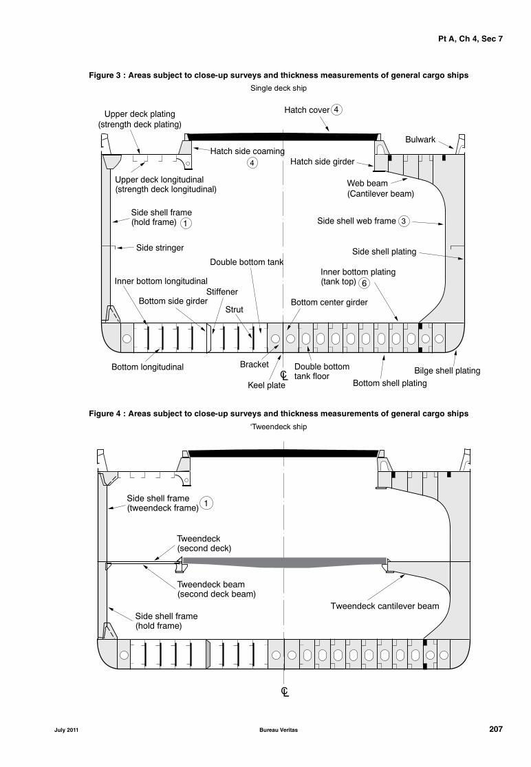
Pt A, Ch 4, Sec 7
Figure 3 : Areas subject to close-up surveys and thickness measurements of general cargo ships
Single deck ship
Figure 4 : Areas subject to close-up surveys and thickness measurements of general cargo ships
‘Tweendeck ship
����� ���� ��� �
����� ��� ���� ��� ��
����� ���� � ������ ����� ��� ���� � ������ �
���� ���� ���
� �� ������ � ������
������ ���� ������
������ � ������
����� ������ � �
������ ��
�����
���� ���� ������
��� ���
�� ������ ����
���� ��� �� ����
���� ��� ��� �
������ �� ��� ������
����� ������� � ����
������ ��� ��� �
���� ��� ��� �
���� ����� !
���� ���� ���� �
!
���� ��� �������� ����� " #
� �� ������ ��� ��� � ���� $
�%
�� ��
������
&�� ���
���� ����� ��� ��������� ����
�
��������� ��������� ����
��
��������� ������ �����
��������� ���� ������ ���� �����
���� ����� ��� ���� ����
July 2011 Bureau Veritas 207
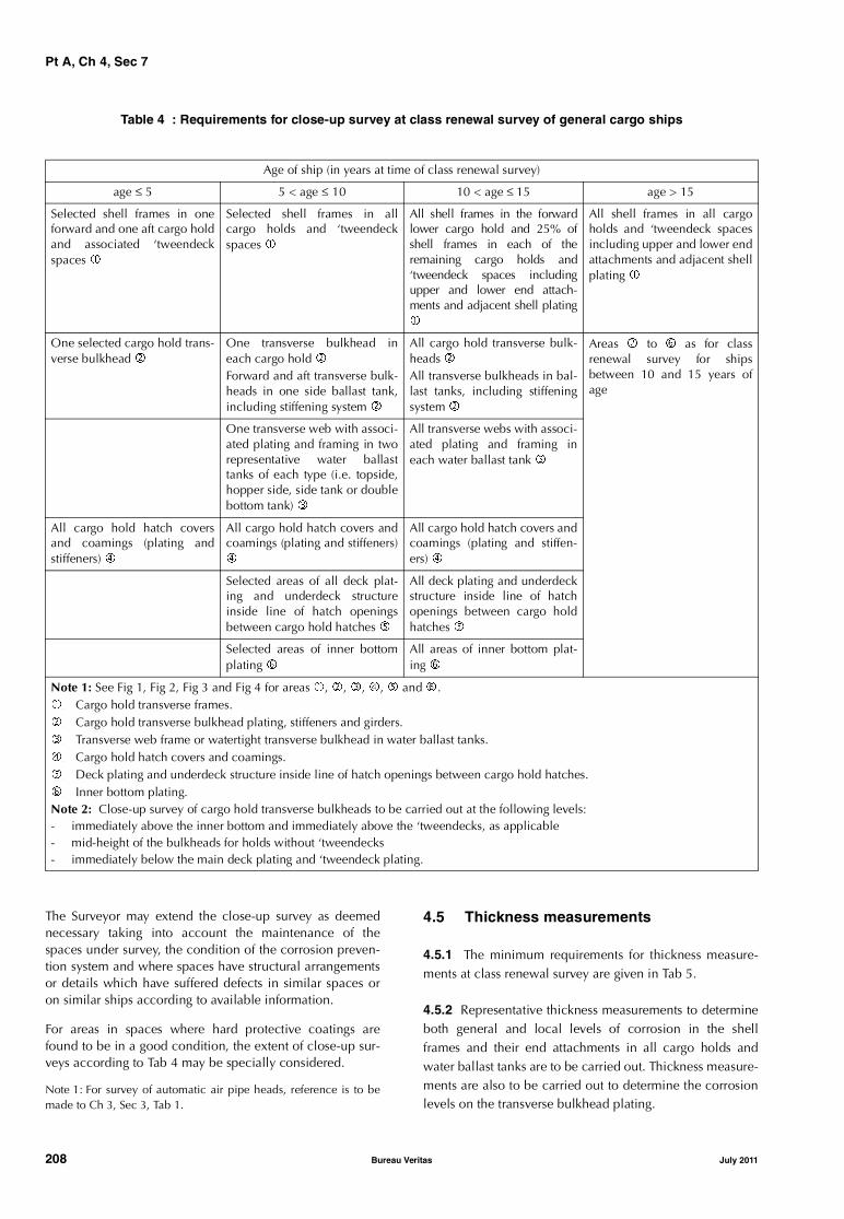
Pt A, Ch 4, Sec 7
Table 4 : Requirements for close-up survey at class renewal survey of general cargo ships
The Surveyor may extend the close-up survey as deemednecessary taking into account the maintenance of thespaces under survey, the condition of the corrosion preven-tion system and where spaces have structural arrangementsor details which have suffered defects in similar spaces oron similar ships according to available information.
For areas in spaces where hard protective coatings arefound to be in a good condition, the extent of close-up sur-veys according to Tab 4 may be specially considered.
Note 1: For survey of automatic air pipe heads, reference is to bemade to Ch 3, Sec 3, Tab 1.
4.5 Thickness measurements
4.5.1 The minimum requirements for thickness measure-ments at class renewal survey are given in Tab 5.
4.5.2 Representative thickness measurements to determineboth general and local levels of corrosion in the shellframes and their end attachments in all cargo holds andwater ballast tanks are to be carried out. Thickness measure-ments are also to be carried out to determine the corrosionlevels on the transverse bulkhead plating.
Age of ship (in years at time of class renewal survey)
age ≤ 5 5 < age ≤ 10 10 < age ≤ 15 age > 15
Selected shell frames in oneforward and one aft cargo holdand associated ‘tweendeckspaces �
Selected shell frames in allcargo holds and ‘tweendeckspaces �
All shell frames in the forwardlower cargo hold and 25% ofshell frames in each of theremaining cargo holds and‘tweendeck spaces includingupper and lower end attach-ments and adjacent shell plating�
All shell frames in all cargoholds and ‘tweendeck spacesincluding upper and lower endattachments and adjacent shellplating �
One selected cargo hold trans-verse bulkhead �
One transverse bulkhead ineach cargo hold � Forward and aft transverse bulk-heads in one side ballast tank,including stiffening system �
All cargo hold transverse bulk-heads � All transverse bulkheads in bal-last tanks, including stiffeningsystem �
Areas � to � as for classrenewal survey for shipsbetween 10 and 15 years ofage
One transverse web with associ-ated plating and framing in tworepresentative water ballasttanks of each type (i.e. topside,hopper side, side tank or doublebottom tank) �
All transverse webs with associ-ated plating and framing ineach water ballast tank �
All cargo hold hatch coversand coamings (plating andstiffeners) �
All cargo hold hatch covers andcoamings (plating and stiffeners)�
All cargo hold hatch covers andcoamings (plating and stiffen-ers) �
Selected areas of all deck plat-ing and underdeck structureinside line of hatch openingsbetween cargo hold hatches �
All deck plating and underdeckstructure inside line of hatchopenings between cargo holdhatches �
Selected areas of inner bottomplating �
All areas of inner bottom plat-ing �
Note 1: See Fig 1, Fig 2, Fig 3 and Fig 4 for areas �, �, �, �, � and �.� Cargo hold transverse frames.� Cargo hold transverse bulkhead plating, stiffeners and girders.� Transverse web frame or watertight transverse bulkhead in water ballast tanks.� Cargo hold hatch covers and coamings.� Deck plating and underdeck structure inside line of hatch openings between cargo hold hatches.� Inner bottom plating.Note 2: Close-up survey of cargo hold transverse bulkheads to be carried out at the following levels:- immediately above the inner bottom and immediately above the ‘tweendecks, as applicable- mid-height of the bulkheads for holds without ‘tweendecks- immediately below the main deck plating and ‘tweendeck plating.
208 Bureau Veritas July 2011

Pt A, Ch 4, Sec 7
Table 5 : Requirements for thickness measurements at class renewal surveys of general cargo ships
4.5.3 The thickness measurements may be dispensed withprovided the Surveyor is satisfied, by the close-up examina-tion, that there is no structural diminution and that the hardprotective coating, where applied, remains efficient.
4.5.4 The Surveyor may extend the thickness measure-ments as deemed necessary. When thickness measurementsindicate substantial corrosion, the extent of thickness meas-urements is to be increased to determine the extent of areasof substantial corrosion in accordance with the require-ments given in Tab 6.
4.5.5 For areas in tanks where hard protective coatings arefound to be in a good condition, the extent of thicknessmeasurements according to Tab 5 may be specially consid-ered.
4.6 Tank testing
4.6.1 All boundaries of water ballast tanks and deep tanksused for water ballast within the cargo length area are to bepressure tested. For fuel oil tanks, the representative tanksare to be pressure tested.
4.6.2 The Surveyor may extend the tank testing as deemednecessary.
4.6.3 Tank testing of fuel oil tanks is to be carried out witha head of liquid to the highest point that liquid will riseunder service conditions. Tank testing of fuel oil tanks maybe specially considered based on a satisfactory externalexamination of the tank boundaries, and a confirmationfrom the Master stating that the pressure testing has beencarried out according to the requirements with satisfactoryresults.
Table 6 : Requirements for extent of thickness measurements at those areas of substantial corrosionClass renewal survey of general cargo ships
Age of ship (in years at time of class renewal survey)
age ≤ 5 5 < age ≤ 10 10 < age ≤15 age > 15
Suspect areas Suspect areas Suspect areas Suspect areas
One transverse section of deck plat-ing in way of a cargo space withinthe amidships 0,5 L (1)
Two transverse sections within theamidships 0,5 L in way of two differ-ent cargo spaces (1)
Within the cargo length area, eachdeck plate outside line of cargohatch openings
Within the cargo length area:• a minimum of three transverse
sections within the amidships0,5 L (1)
• each deck plate outside line ofcargo hatch openings
• each bottom plate, includinglower turn of bilge
• duct keel or pipe tunnel platingand internals
Measurement, for general assess-ment and recording of corrosion pat-tern, of those structural memberssubject to close-up survey accordingto Tab 4
Measurement, for general assess-ment and recording of corrosion pat-tern, of those structural memberssubject to close-up survey accordingto Tab 4
Measurement, for general assess-ment and recording of corrosion pat-tern, of those structural memberssubject to close-up survey accordingto Tab 4
All wind and water strakes withinthe cargo area
All wind and water strakes fulllength
Selected wind and water strakes out-side the cargo area
(1) Transverse sections are to be chosen where the largest reductions are suspected to occur or are revealed from deck platingmeasurements.
Note 1: Thickness measurement locations should be selected to provide the best representative sampling of areas likely to be mostexposed to corrosion, considering cargo and ballast history and arrangement and condition of protective coatings.Note 2: For ships less than 100 metres in length, the number of transverse sections required for ships between 10 and 15 years of agemay be reduced to one and the number of transverse sections for ships over 15 years of age may be reduced to two.
Structural member Extent of measurement Pattern of measurement
Plating Suspect area and adjacent plates 5-point pattern over 1 m2 of plating
Stiffeners Suspect area 3 measurements each in line across web and flange
July 2011 Bureau Veritas 209
Pt A, Ch 4, Sec 8
SECTION 8 OTHER SERVICE NOTATIONS
1 General
1.1
1.1.1 The requirements of this Section are applicable toships to be assigned one of the following service notations,and given in the Articles specified below:
• container ship, or ship equipped for the carriage ofcontainers, in Article [2]
• livestock carrier, in Article [3]
• FLS tanker, in Article [4]
• dredging units, i.e. ships with the service notationsdredger, hopper dredger, hopper unit, split hopperunit, split hopper dredger, in Article [5]
• tug, salvage tug, escort tug, in Article [6]
• supply vessel, in Article [7]
• fire-fighting ship, in Article [8]
• oil recovery ship, in Article [9]
• cable laying ship, in Article [10]
• fishing vessel, in Article [11]
• special service - standby rescue vessel, in Article [12]
• yachts and charter yachts, in Article [13].
1.1.2 These requirements are additional to those given inPart A, Chapter 3, according to the relevant surveys.
2 Container ship or ship equipped for the carriage of containers
2.1 Annual survey
2.1.1 The survey is to include:
• confirmation of the availability of instructions and instru-ments for stowage of containers, as required or fitted
• examination of container supports welded to the ship’sstructure or on to the hatch covers
• examination of cell guides, if fitted.
2.2 Class renewal survey
2.2.1 The renewal is to include:
• examination of container supports welded to the ship’sstructure or on to the hatch covers, checking for possi-ble cracks and deformations
• examination of cell guides and associated elements,checking for possible cracks, deformations or corrosion.
2.2.2 For ships assigned with the service notation containership, examination of the torsion box girder or equivalentstructure at the top sides is carried out. Thickness measure-ments additional to those related to the transverse sectionsmay be required.
3 Livestock carrier
3.1 Annual survey
3.1.1 The survey is to include a general examination of:
• spaces for the livestock and related hatch covers (to besurveyed according to Ch 3, Sec 1, [2])
• ventilation means, including prime movers
• main, emergency and portable lighting systems in live-stock spaces, passageways and access routes
• the drainage system
• fodder and fresh water systems
• fire-fighting appliances, with working test as far as nec-essary and practicable (according to Ch 3, Sec 1, [3.4])
• means of escape, with confirmation they are kept clear.
3.2 Class renewal survey
3.2.1 The equipment related to ventilation, lighting and therelated power supply is to be submitted to a survey to thesame extent as required for similar equipment at the classrenewal survey as indicated in Ch 3, Sec 3.
3.2.2 The drainage, fodder and fresh water systems, includ-ing piping and pumps, are to be surveyed to the same extentas required for similar equipment at the class renewal sur-vey as indicated in Ch 3, Sec 3.
The fresh water tanks are to be internally examined inaccordance with the periodicity given in Ch 3, Sec 3, Tab 2.
3.2.3 The fire-fighting systems are to be thoroughly exam-ined and tested.
4 FLS tanker
4.1 Annual survey - Hull items
4.1.1 Weather decksThe survey is to include:
• examination of cargo tank openings, including gaskets,covers, coamings and screens
• examination of cargo tank pressure/vacuum valves andflame screens
• examination of flame screens on vents to all bunker, oilyballast and oily slop tanks
210 Bureau Veritas July 2011

Pt A, Ch 4, Sec 8
• examination of cargo, bunker, ballast and vent pipingsystems, including remote control valves, safety valvesand various safety devices, as well as vent masts andheaders
• confirmation that wheelhouse doors and windows, side-scuttles and windows in superstructure and deckhouseends facing the cargo area are in satisfactory condition
• confirmation that pumps, valves and pipelines are iden-tified and distinctively marked.
4.1.2 Cargo pump rooms and pipe tunnels
The survey is to include:
• examination of all pump room bulkheads and pipe tun-nels (if any) for signs of chemical cargo leakage or frac-tures and, in particular, the sealing arrangements ofpenetrations in pump room bulkheads
• examination of the condition of all piping systems, incargo pump rooms and pipe tunnels (if any)
• examination of the bilge and ballast arrangements andconfirmation that pumps and pipelines are identified.
4.2 Annual survey - Cargo machinery items
4.2.1 Cargo area and cargo pump rooms
The Owner or his representative is to declare to the attend-ing Surveyor that no modifications or alterations whichmight impair safety have been made to the various installa-tions in dangerous zones without prior approval from theSociety.
The survey is to include:
• confirmation that potential sources of ignition in or nearthe cargo pump rooms, such as loose gear, excessiveproduct in bilge, excessive vapours, combustible mate-rials, are eliminated and that access ladders are in satis-factory condition
• examination, as far as practicable, of cargo, bilge, bal-last and stripping pumps for excessive gland seal leak-age, verification of proper operation of electrical andmechanical remote operating and shutdown devicesand operation of pump room bilge system, and check-ing that pump foundations are intact
• confirmation that the ventilation system, including port-able equipment, if any, of all spaces in the cargo area(including cargo pump room) is operational, ducting isintact, dampers are operational and screens are clean
• confirmation that electrical equipment in dangerouszones, cargo pump rooms and other spaces is in satis-factory condition and has been properly maintained
• confirmation that the remote operation of the cargopump room bilge system is satisfactory
• examination of the cargo heating system
• examination of the cargo-transfer arrangement and con-firmation that the ship's cargo hoses are suitable fortheir intended purpose and in satisfactory condition
• confirmation that any special arrangement made forbow or stern loading/unloading is in satisfactory condi-tion.
4.2.2 Instrumentation and safety devices
The survey is to include the following items, as far asrequired or fitted:
• examination of cargo tank gauging devices, high levelalarms and valves associated with overflow control
• confirmation that installed pressure gauges on cargo dis-charge lines are properly operational
• confirmation that the required gas detection instrumentsare on board and satisfactory arrangements have beenmade for the supply of any required vapour detectiontubes
• confirmation that devices provided for measuring thetemperature of the cargo, if any, operate satisfactorily.
4.2.3 Fire-fighting systems
The survey is to include:
• external examination of piping and cut-out valves offixed fire-fighting systems related to cargo tanks andcargo pump rooms
• confirmation, as far as practicable and when appropri-ate, that the remote means for closing the various open-ings are operable
• examination of the appropriate portable fire-extinguish-ing equipment for the chemical cargoes to be carried inaccordance with the relevant requirements given in Ch3, Sec 1, [3.4.3]
• examination of fire-fighting systems of any type fitted onboard such as deck foam, water-spraying, etc. as appli-cable in accordance with the relevant requirementsgiven in Ch 3, Sec 1, [3.4.2].
4.2.4 Inert gas system
If an inert gas system such as that installed on board oiltankers is fitted, the requirements given in Ch 4, Sec 3, [3.4]are to be complied with.
4.3 Intermediate survey - Hull items
4.3.1 The survey is to include:
• examination, as far as applicable, of cargo, stripping,cargo washing, bunker, ballast, steam and vent pipingsystems as well as vent masts and headers. If uponexamination there is any doubt as to the condition ofthe piping, pressure testing, thickness measurement orboth may be required
• confirmation, if applicable, that cargo pipes are electri-cally bonded to the hull
• examination of vent line drainage arrangements.
July 2011 Bureau Veritas 211
Pt A, Ch 4, Sec 8
4.4 Intermediate survey - Cargo machinery items
4.4.1 Electrical equipment in dangerous zonesA general examination of the electrical equipment andcables in dangerous zones such as cargo pump rooms andareas adjacent to cargo tanks is to be carried out for defec-tive and non-certified safe type electrical equipment, non-approved lighting and fixtures, and improperly installed ordefective or dead-end wiring.
The electrical insulation resistance of the electrical equip-ment and circuits terminating in or passing through the dan-gerous zones is to be tested; however, in cases where aproper record of testing is maintained, consideration maybe given to accepting recent test readings effected by theship’s personnel.
4.4.2 Cargo heating systemThe satisfactory condition of the cargo heating system is tobe verified.
4.4.3 Inert gas systemFor ships over 10 years old at the time of the intermediatesurvey due date, if an inert gas system such as that installedon board oil tankers is fitted, the requirements given in Ch4, Sec 3, [5.2] for intermediate survey of oil tankers are tobe complied with.
4.5 Class renewal survey - Hull items
4.5.1 PipingPiping for cargo, ballast, stripping and venting systems is tobe examined to the Surveyor's satisfaction. Dismantlingand/or thickness measurements of these items may berequired. A hydraulic test is to be carried out in the event ofrepair or dismantling of cargo or ballast piping, or wheredoubts arise.
Vent line drainage arrangements are to be examined.
It is to be verified, when applicable, that cargo piping iselectrically bonded to the hull.
4.5.2 Safety valvesAll safety valves on cargo piping and of cargo tanks are tobe dismantled for examination, adjusted and, as applicable,resealed.
4.5.3 Cargo pump roomsAll cargo pump room boundaries are to be generally exam-ined. All gas-tight shaft sealing devices are to be examined.The bottom of cargo pump rooms is to be presented cleanfor the examination of stripping devices and gutters.
4.6 Class renewal survey - Cargo machinery items
4.6.1 PumpsBallast and stripping pumps are to be internally examinedand prime movers checked. A working test is to be carriedout.
Maintenance records of cargo pumps are to be made availa-ble to the Surveyor.
4.6.2 Washing system
Where a washing system is fitted, piping, pumps, valves anddeck-mounted washing machines are to be examined andtested for signs of leakage, and anchoring devices of deck-mounted washing machines are to be checked to the Sur-veyor's satisfaction.
4.6.3 Cargo heating system
The apparent satisfactory condition of the cargo heating sys-tem such as clamping, external condition of piping is to beverified and, if deemed necessary by the Surveyor, the sys-tem is to be pressure tested.
4.6.4 Remote controls
An operating test of the emergency remote control of pumpsand valves and of automatic closing valves is to be carriedout.
4.6.5 Electrical equipment in dangerous zones
A general examination of the electrical equipment andcables in dangerous zones such as cargo pump rooms andareas adjacent to cargo tanks is to be carried out for defec-tive and non-certified safe type electrical equipment, non-approved lighting and fixtures, and improperly installed ordefective or dead-end wiring.
The electrical insulation resistance of the electrical equip-ment and circuits terminating in or passing through the dan-gerous zones is to be tested; however, in cases where aproper record of testing is maintained, consideration maybe given to accepting recent test readings effected by theship’s personnel.
4.6.6 Fire-fighting systems
The survey is to include the examination of fire-fighting sys-tems of any type fitted on board for the protection of thecargo area, cargo pump room and other dangerous spaces,such as deck foam, water-spraying, etc., as applicable inaccordance with the relevant requirements given in Ch 3,Sec 3, [3.8].
4.6.7 Inert gas system
If an inert gas system such as that installed on board oiltankers is fitted, the requirements given in Ch 4, Sec 3, [5.2]for intermediate survey and in Ch 4, Sec 3, [7.3] for classrenewal survey of oil tankers are to be complied with.
5 Dredging units
5.1 Annual survey
5.1.1 The survey is to include the following items, as far asrequired or fitted, according to the service notation of theship:
• for split hopper unit, split hopper dredger, visual exam-ination, as far as practicable, of superstructure hingesand blocks, deck hinges, hydraulic jacks and associatedpiping systems and alarms
212 Bureau Veritas July 2011

Pt A, Ch 4, Sec 8
• for dredger, hopper dredger, split hopper dredger: - visual examination, as far as practicable, of attach-
ments of suction piping and lifting systems to thestructure and external examination of piping indredging machinery spaces for absence of corrosionand leakage
- checking the condition of the dredging machineryspace and related equipment with regard to electri-cal shocks, protection from rotating machinery, fireand explosion hazards.
5.2 Class renewal survey
5.2.1 The survey is to include the following items, as far asrequired or fitted, according to the service notation of theship: • for hopper dredger, hopper unit, visual examination of
hopper bottom doors or valves and accessories, such ashinges, actuating rods, hydraulic systems, with disman-tling as deemed necessary by the Surveyor
• for split hopper unit, split hopper dredger, visual exam-ination, as far as practicable, of superstructure hingesand blocks, deck hinges, hydraulic jacks and associatedpiping systems and alarms, with dismantling and/or fur-ther checks as deemed necessary by the Surveyor
• for dredger, hopper dredger, split hopper dredger:- visual examination, as far as practicable, of attach-
ments of suction piping and lifting systems to thestructure and external examination of piping indredging machinery spaces for absence of corrosionand leakage
- checking the condition of the dredging machineryspace and related equipment with regard to electri-cal shocks, protection from rotating machinery, fireand explosion hazards.
6 Tug, salvage tug, escort tug
6.1 Annual survey
6.1.1 The survey is to include a general external examina-tion of the towing hook or towing winch, as fitted, andunhooking device, as far as practicable.
6.1.2 In addition to [6.1.1], for salvage tug, the availabilityand satisfactory condition of specific equipment as requiredin Pt D, Ch 14, Sec 2, [3] is to be verified.
6.1.3 For tug-barge combined, an examination of theaccessible parts of the connection system is to be carriedout.
6.2 Class renewal survey
6.2.1 The survey is to include:• checking the condition of the connection of the towing
hook or towing winch to the structure, including relatedreinforcements of the structure
• checking the external condition of the towing hook ortowing winch; when applicable, a no-load test of theunhooking device is to be carried out.
6.2.2 In addition to [6.2.1], for salvage tug, the survey is toinclude:
• a check and working test of specific equipment asrequired in Pt D, Ch 14, Sec 2, [3]
• checking by a specialist of the satisfactory condition ofthe towing line(s). A report is to be presented to the Sur-veyor by the Owner and kept on board.
6.2.3 For tug-barge combined, a visual examination ofcomponents of the connection system is to be carried out,completed by thickness measurements and non-destructivetests as deemed necessary by the Surveyor. A connec-tion/disconnection test is to be carried out, including acheck of related remote control, safety and alarm devices.
7 Supply vessel-oil product or supply vessel-chemical product
7.1 General
7.1.1 The additional survey items for annual survey, inter-mediate survey and class renewal survey are applicableonly to ships having the service notation supply vesselassigned the additional service features oil product, LHNSor WS.
7.2 Annual survey - Hull items
7.2.1 Weather decks
The survey is to include:
• examination of cargo tank openings, including gaskets,covers, coamings and screens
• examination of cargo tank pressure/vacuum valves andflame screens
• examination of flame screens on vents to all bunker, oilyballast and oily slop tanks
• examination of cargo, bunker, ballast and vent pipingsystems, including remote control valves, safety valvesand various safety devices, as well as vent masts andheaders
• confirmation that wheelhouse doors and windows, side-scuttles and windows in superstructure and deckhouseends facing the cargo area are in satisfactory condition
• confirmation that pumps, valves and pipelines are iden-tified and distinctively marked.
7.2.2 Cargo pump rooms and pipe tunnels
The survey is to include:
• examination of all pump room bulkheads and pipe tun-nels (if any) for signs of oil or chemical product leakageor fractures and, in particular, the sealing arrangementsof penetrations in pump room bulkheads
• examination of the condition of all piping systems, incargo pump rooms and pipe tunnels (if any)
• examination of the bilge and ballast arrangements andconfirmation that pumps and pipelines are identified.
July 2011 Bureau Veritas 213

Pt A, Ch 4, Sec 8
7.3 Annual survey - Cargo machinery items
7.3.1 Cargo area and cargo pump roomsThe Owner or his representative is to declare to the attend-ing Surveyor that no modifications or alterations whichmight impair safety have been made to the various installa-tions in dangerous zones without prior approval from theSociety.
The survey is to include:• confirmation that potential sources of ignition in or near
the cargo pump rooms, such as loose gear, excessiveproduct in bilge, excessive vapours, combustible mate-rials, etc., are eliminated and that access ladders are insatisfactory condition
• examination, as far as practicable, of cargo, bilge, bal-last and stripping pumps for excessive gland seal leak-age, verification of proper operation of electrical andmechanical remote operating and shutdown devicesand operation of pump room bilge system, and check-ing that pump foundations are intact
• confirmation that the ventilation system, including port-able equipment, if any, of all spaces in the cargo area(including cargo pump rooms) is operational, ducting isintact, dampers are operational and screens are clean
• confirmation that electrical equipment in dangerouszones, cargo pump rooms and other spaces is in satis-factory condition and has been properly maintained
• confirmation that the remote operation of the cargopump room bilge system, if fitted, is satisfactory
• examination of the cargo heating system• examination of the cargo-transfer arrangement and con-
firmation that the ship's cargo hoses are suitable fortheir intended purpose and in satisfactory condition.
7.3.2 Instrumentation and safety devicesThe survey is to include the following items, as far asrequired or fitted:• examination of cargo tank gauging devices, high level
alarms and valves associated with overflow control• confirmation that installed pressure gauges on cargo dis-
charge lines are properly operational• confirmation that the required gas detection instruments
are on board and satisfactory arrangements have beenmade for the supply of any required vapour detectiontubes
• confirmation that devices provided for measuring thetemperature of the cargo, if any, operate satisfactorily.
7.3.3 Fire-fighting systemsThe survey is to include:• external examination of piping and cut-out valves of
fixed fire-fighting systems related to cargo tanks andcargo pump rooms
• confirmation, as far as practicable and when appropri-ate, that the remote means for closing the various open-ings are operable
• examination of the appropriate portable fire-extinguish-ing equipment for the cargoes to be carried in accord-ance with the relevant requirements given in Ch 3, Sec1, [3.4.3]
• examination of fire-fighting systems of any type fitted onboard such as deck foam, water-spraying etc. as applica-ble in accordance with the relevant requirements givenin Ch 3, Sec 1, [3.4.2].
7.4 Intermediate survey - Hull items
7.4.1 The survey is to include:• examination, as far as applicable, of cargo, stripping,
bunker, ballast, steam and vent piping systems as wellas vent masts and headers. If upon examination there isany doubt as to the condition of the piping, pressuretesting, thickness measurement or both may be required
• confirmation that the pipelines are electrically bondedto the hull
• examination of vent line drainage arrangements.
7.5 Intermediate survey - Cargo machinery items
7.5.1 Electrical equipment in dangerous zonesA general examination of the electrical equipment andcables in dangerous zones such as cargo pump rooms andareas adjacent to cargo tanks is to be carried out for defec-tive and non-certified safe type electrical equipment, non-approved lighting and fixtures, and improperly installed ordefective or dead-end wiring.
The electrical insulation resistance of the electrical equip-ment and circuits terminating in or passing through the dan-gerous zones is to be tested; however, in cases where aproper record of testing is maintained, consideration maybe given to accepting recent test readings effected by theship’s personnel.
7.5.2 Cargo heating systemThe satisfactory condition of the cargo heating system is tobe verified.
7.6 Class renewal survey - Hull items
7.6.1 PipingPiping for cargo, ballast, stripping and venting systems is tobe examined to the Surveyor's satisfaction. Dismantlingand/or thickness measurements of these items may berequired. A hydraulic test is to be carried out in the event ofrepair or dismantling of cargo or ballast piping, or wheredoubts arise.
Vent line drainage arrangements are to be examined.
It is to be verified that cargo piping is electrically bonded tothe hull.
7.6.2 Safety valvesAll safety valves on cargo piping and of cargo tanks are tobe dismantled for examination, adjusted and, as applicable,resealed.
7.6.3 Cargo pump roomsAll cargo pump room boundaries are to be generally exam-ined. All gas-tight shaft sealing devices are to be examined.The bottom of cargo pump rooms is to be presented cleanfor the examination of stripping devices and gutters.
214 Bureau Veritas July 2011
Pt A, Ch 4, Sec 8
7.7 Class renewal survey - Cargo machinery items
7.7.1 Pumps
Ballast and stripping pumps are to be internally examinedand prime movers checked. A working test is to be carriedout.
Maintenance records of cargo pumps are to be made availa-ble to the Surveyor.
7.7.2 Cargo heating system
The apparent satisfactory condition of the cargo heating sys-tem such as clamping, external condition of piping is to beverified and, if deemed necessary by the Surveyor, the sys-tem is to be pressure tested.
7.7.3 Remote controls
An operating test of the emergency remote control of pumpsand valves and of automatic closing valves is to be carriedout.
7.7.4 Electrical equipment in dangerous zones
A general examination of the electrical equipment andcables in dangerous zones such as cargo pump rooms andareas adjacent to cargo tanks is to be carried out for defec-tive and non-certified safe type electrical equipment, non-approved lighting and fixtures, and improperly installed ordefective or dead-end wiring.
The electrical insulation resistance of the electrical equip-ment and circuits terminating in or passing through the dan-gerous zones is to be tested; however, in cases where aproper record of testing is maintained, consideration maybe given to accepting recent test readings effected by theship’s personnel.
7.7.5 Fire-fighting systems
The survey is to include the examination of fire-fighting sys-tems of any type fitted on board for the protection of thecargo area, cargo pump room and other dangerous spaces,such as deck foam, water-spraying, dry powder systems etc.,as applicable in accordance with the relevant requirementsgiven in Ch 3, Sec 3, [3.8].
8 Fire-fighting ship
8.1 Annual survey
8.1.1 Ship’s fire protection
The survey is to include:
• general examination of arrangements for structural fireprotection
• ships equipped with a self-protection water-sprayingsystem: general examination of all parts, as far as practi-cable and visible, of self-protection water-spraying sys-tem, and of scuppers and freeing ports for waterdrainage from deck surfaces
• ships not equipped with a self-protection water-sprayingsystem: general examination of steel deadlights andshutters.
8.1.2 Water monitor system
The survey is to include:
• general examination of all parts of the water monitorsystem (pumps, piping system, valves and other fittings)
• checking for proper operation of the system, includinglocal manual control
• general examination of foundations of water monitorsand check of local manual control.
8.1.3 Fixed and portable foam systems
The survey is to include:
• general examination of the systems
• confirmation that the foam concentrates are periodicallytested, either by the Manufacturer or by an organisationagreed by him
• general examination of foundations of foam monitorsand check of local manual control
• for fixed foam systems, reference is to be made to Ch 3,Sec 1, [3.4.2], item e).
8.1.4 Machinery installations, control room and other devices
The survey is to include:
• general examination of spaces containing auxiliarymachinery for fire-fighting systems, particular attentionbeing paid to arrangements, piping systems and instru-ments; check of tools and of pressure vessels and theirfittings, if any
• general examination of the control station and check ofall communication and remote control means, of venti-lation system
• general examination of sea suctions of fire-fighting sys-tems, of relevant remote and local control and of pipingsystems, including the relevant protection against corro-sion
• general external examination of electrical installationsfor fire-fighting systems, with particular regard to thealarms and searchlights,
• checking of other fire-fighting arrangements
• checking of firemen’s outfits, confirmation that they arestored in the appropriate locations, and checking of aircompressor and other equipment.
8.2 Class renewal survey
8.2.1 The survey is to include:
• complete test of water fire-extinguishing systems,including the internal examination, as required by theSurveyor, of the relevant pumps
• partial test, at the Surveyor's discretion, of fixed foamfire-extinguishing systems
• test of self-protection fixed water-spraying systems,putting into operation the spray nozzles, including theinternal examination, as required by the Surveyor, of therelevant pumps
July 2011 Bureau Veritas 215
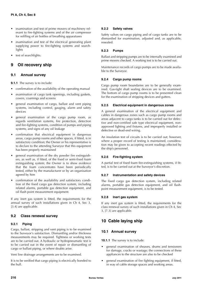
Pt A, Ch 4, Sec 8
• examination and test of prime movers of machinery rel-evant to fire-fighting systems and of the air compressorfor refilling of air bottles of breathing apparatuses
• examination and test of the electrical generating plantsupplying power to fire-fighting systems and search-lights
• test of searchlights.
9 Oil recovery ship
9.1 Annual survey
9.1.1 The survey is to include:
• confirmation of the availability of the operating manual
• examination of cargo tank openings, including gaskets,covers, coamings and screens
• general examination of cargo, ballast and vent pipingsystems, including control, gauging, alarm and safetydevices
• general examination of the cargo pump room, asregards ventilation systems, fire protection, detectionand fire-fighting systems, condition of pumps and pipingsystems, and signs of any oil leakage
• confirmation that electrical equipment in dangerousareas, cargo pump rooms and other spaces, if fitted, is insatisfactory condition; the Owner or his representative isto declare to the attending Surveyor that this equipmenthas been properly maintained
• general examination of the dry powder fire extinguish-ers, as well as, if fitted, of the fixed or semi-fixed foamextinguishing system; the Owner is to show evidencethat the foam concentrates have been periodicallytested, either by the manufacturer or by an organisationagreed by him
• confirmation of the availability and satisfactory condi-tion of the fixed cargo gas detection system, includingrelated alarms, portable gas detection equipment, andoil flash point measurement equipment.
If any inert gas system is fitted, the requirements for theannual survey of such installations given in Ch 4, Sec 3,[3.4] are applicable.
9.2 Class renewal survey
9.2.1 Piping
Cargo, ballast, stripping and vent piping is to be examinedto the Surveyor's satisfaction. Dismantling and/or thicknessmeasurements may be required. Tightness or working testsare to be carried out. A hydraulic or hydropneumatic test isto be carried out in the event of repair or dismantling ofcargo or ballast piping, or where doubts arise.
Vent line drainage arrangements are to be examined.
It is to be verified that cargo piping is electrically bonded tothe hull.
9.2.2 Safety valves
Safety valves on cargo piping and of cargo tanks are to bedismantled for examination, adjusted and, as applicable,resealed.
9.2.3 Pumps
Ballast and stripping pumps are to be internally examined andprime movers checked. A working test is to be carried out.
Maintenance records of cargo pumps are to be made availa-ble to the Surveyor.
9.2.4 Cargo pump rooms
Cargo pump room boundaries are to be generally exam-ined. Gas-tight shaft sealing devices are to be examined.The bottom of cargo pump rooms is to be presented cleanfor the examination of stripping devices and gutters.
9.2.5 Electrical equipment in dangerous zones
A general examination of the electrical equipment andcables in dangerous zones such as cargo pump rooms andareas adjacent to cargo tanks is to be carried out for defec-tive and non-certified safe type electrical equipment, non-approved lighting and fixtures, and improperly installed ordefective or dead-end wiring.
An insulation test of circuits is to be carried out; however,where a proper record of testing is maintained, considera-tion may be given to accepting recent readings effected bythe ship’s personnel.
9.2.6 Fire-fighting system
A partial test of fixed foam fire-extinguishing systems, if fit-ted, is to be carried out at the Surveyor's discretion.
9.2.7 Instrumentation and safety devices
The fixed cargo gas detection system, including relatedalarms, portable gas detection equipment, and oil flash-point measurement equipment, is to be tested.
9.2.8 Inert gas system
If any inert gas system is fitted, the requirements for theclass renewal survey of such installations given in Ch 4, Sec3, [7.3] are applicable.
10 Cable laying ship
10.1 Annual survey
10.1.1 The survey is to include:
• general examination of sheaves, drums and tensionersfor damage, cracks or wastage; the connections of theseappliances to the structure are also to be checked
• general examination of fire fighting equipment, if fitted,in way of cable storage spaces and working areas.
216 Bureau Veritas July 2011

Pt A, Ch 4, Sec 8
10.2 Class renewal survey
10.2.1 The equipment mentioned in [10.1.1] is to be dis-mantled, to the extent deemed necessary by the Surveyor, inorder to check its condition. Clearances of sheaves andcable drum axles are to be ascertained.
10.2.2 Fire-fighting equipment is to be submitted to a sur-vey to the same extent as required for similar equipment atthe class renewal survey for all ships (see Ch 3, Sec 3).
11 Fishing vessel
11.1 Annual survey
11.1.1 The survey is to include:
• general examination of areas subject to damage, corro-sion or wastage, such as the stern ramp, weather deck inway of the working area of the nets, connections to hullstructure of masts, gantries, winches and trawl gallows(for side trawlers)
• general examination of the measures for the protectionof the crew against falling overboard, such as stormrails, means of protection near stern ramp, etc.
11.2 Class renewal survey
11.2.1 For fishing vessels 10 years age and over, the classrenewal survey is to include thickness measurements ofstructural elements prone to rapid wastage, such as the sternramp, weather deck in way of the working area of the nets,connections to hull structure of masts, gantries, winchesand trawl gallows (for side trawlers).
12 Special service - standby rescue vessel
12.1 Annual survey - Rescue arrangement, survivors accommodation and safety equipment
12.1.1 A general examination of rescue equipment andfacilities, survivors spaces, safety equipment, personal careand medical provisions, in accordance with the require-ments given in Rule Note NR482, Section 4, is to be carriedout.
12.2 Annual survey - Towing arrangements
12.2.1 A general external examination of the towing hookor towing winch, as fitted, and unhooking device, as far aspracticable, is to be carried out.
12.3 Class renewal survey - Rescue arrangement, survivors accommodation and safety equipment
12.3.1 A general examination of rescue equipment andfacilities, survivors spaces, safety equipment, personal careand medical provisions, in accordance with the require-ments given in NR482, Section 4, is to be carried out.
Testing of rescue and safety equipment, as applicable, is tobe carried out.
12.4 Class renewal survey - Towing arrangements
12.4.1 The survey is to include:
• checking the condition of the connection of the towinghook or towing winch to the structure, including relatedreinforcements of the structure
• checking the external condition of the towing hook ortowing winch; when applicable, a no-load test of theunhooking device is to be carried out.
13 Yachts and charter yachts
13.1 Intermediate survey - Hull and hull equipment
13.1.1 The survey is to include a general external examina-tion of:
• superstructures, coachroofs, hatches, companionways,ventilator and air pipe coamings, skylights, flush deckscuttles and other openings
• all closing appliances which protect openings in thedeck
• hull side openings with their securing appliances
• freeing port shutters provided in bulwarks
• anchors, chain cables and windlasses
• fastenings, including those through the ballast keel, asfar as possible
• structural reinforcements in way of masts and chainplates
• hull condition in way of openings.
Testing of the above is to be carried out as appropriate.
The steering gear arrangement is to be examined and testedincluding its associated equipment and control systems.
13.2 Intermediate survey - Machinery and systems
13.2.1 Ships assigned with the service notation yacht andhaving a length less than 24 m are submitted to a surveywhich scope is as indicated in Ch 3, Sec 1, [3].
July 2011 Bureau Veritas 217
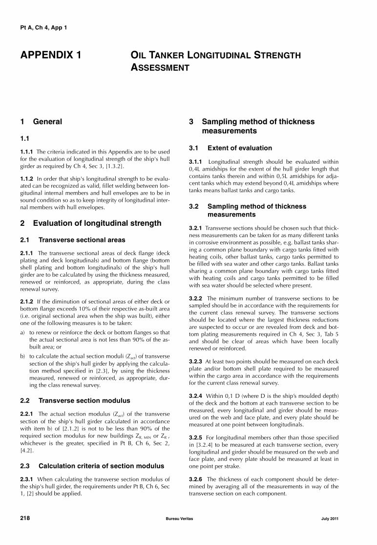
Pt A, Ch 4, App 1
APPENDIX 1 OIL TANKER LONGITUDINAL STRENGTH ASSESSMENT
1 General
1.1
1.1.1 The criteria indicated in this Appendix are to be usedfor the evaluation of longitudinal strength of the ship's hullgirder as required by Ch 4, Sec 3, [1.3.2].
1.1.2 In order that ship's longitudinal strength to be evalu-ated can be recognized as valid, fillet welding between lon-gitudinal internal members and hull envelopes are to be insound condition so as to keep integrity of longitudinal inter-nal members with hull envelopes.
2 Evaluation of longitudinal strength
2.1 Transverse sectional areas
2.1.1 The transverse sectional areas of deck flange (deckplating and deck longitudinals) and bottom flange (bottomshell plating and bottom longitudinals) of the ship's hullgirder are to be calculated by using the thickness measured,renewed or reinforced, as appropriate, during the classrenewal survey.
2.1.2 If the diminution of sectional areas of either deck orbottom flange exceeds 10% of their respective as-built area(i.e. original sectional area when the ship was built), eitherone of the following measures is to be taken:
a) to renew or reinforce the deck or bottom flanges so thatthe actual sectional area is not less than 90% of the as-built area; or
b) to calculate the actual section moduli (Zact) of transversesection of the ship's hull girder by applying the calcula-tion method specified in [2.3], by using the thicknessmeasured, renewed or reinforced, as appropriate, dur-ing the class renewal survey.
2.2 Transverse section modulus
2.2.1 The actual section modulus (Zact) of the transversesection of the ship's hull girder calculated in accordancewith item b) of [2.1.2] is not to be less than 90% of therequired section modulus for new buildings ZR, MIN or ZR ,whichever is the greater, specified in Pt B, Ch 6, Sec 2,[4.2].
2.3 Calculation criteria of section modulus
2.3.1 When calculating the transverse section modulus ofthe ship's hull girder, the requirements under Pt B, Ch 6, Sec1, [2] should be applied.
3 Sampling method of thickness measurements
3.1 Extent of evaluation
3.1.1 Longitudinal strength should be evaluated within0,4L amidships for the extent of the hull girder length thatcontains tanks therein and within 0,5L amidships for adja-cent tanks which may extend beyond 0,4L amidships wheretanks means ballast tanks and cargo tanks.
3.2 Sampling method of thickness measurements
3.2.1 Transverse sections should be chosen such that thick-ness measurements can be taken for as many different tanksin corrosive environment as possible, e.g. ballast tanks shar-ing a common plane boundary with cargo tanks fitted withheating coils, other ballast tanks, cargo tanks permitted tobe filled with sea water and other cargo tanks. Ballast tankssharing a common plane boundary with cargo tanks fittedwith heating coils and cargo tanks permitted to be filledwith sea water should be selected where present.
3.2.2 The minimum number of transverse sections to besampled should be in accordance with the requirements forthe current class renewal survey. The transverse sectionsshould be located where the largest thickness reductionsare suspected to occur or are revealed from deck and bot-tom plating measurements required in Ch 4, Sec 3, Tab 5and should be clear of areas which have been locallyrenewed or reinforced.
3.2.3 At least two points should be measured on each deckplate and/or bottom shell plate required to be measuredwithin the cargo area in accordance with the requirementsfor the current class renewal survey.
3.2.4 Within 0,1 D (where D is the ship’s moulded depth)of the deck and the bottom at each transverse section to bemeasured, every longitudinal and girder should be meas-ured on the web and face plate, and every plate should bemeasured at one point between longitudinals.
3.2.5 For longitudinal members other than those specifiedin [3.2.4] to be measured at each transverse section, everylongitudinal and girder should be measured on the web andface plate, and every plate should be measured at least inone point per strake.
3.2.6 The thickness of each component should be deter-mined by averaging all of the measurements in way of thetransverse section on each component.
218 Bureau Veritas July 2011

Pt A, Ch 4, App 1
3.3 Additional measurements
3.3.1 Where one or more of the transverse sections arefound to be deficient in respect of the longitudinal strengthrequirements given in this Appendix, the number of trans-verse sections for thickness measurements should beincreased such that each tank within the 0,5L amidshipsregion has been sampled. Tank spaces that are partiallywithin, but extend beyond, the 0,5 L region should be sam-pled.
3.3.2 Additional thickness measurements should also beperformed on one transverse section forward and one aft ofeach repaired area to the extent necessary to ensure that theareas bordering the repaired section also comply with therequirements of this Appendix.
3.4 Repair methods
3.4.1 The extent of renewal or reinforcement carried out tocomply with this Appendix should be in accordance with[3.4.2].
3.4.2 The minimum continuous length of a renewed orreinforced structural member should be not less than twicethe spacing of the primary members in way. In addition, thethickness diminution in way of the butt joint of each joiningmember forward and aft of the replaced member (plates,stiffeners, girder webs and flanges, etc.) should not bewithin the substantial corrosion range (75% of the allowa-
ble diminution associated with each particular member).Where differences in thickness at the butt joint exceed 15%of the lower thickness, a transition taper should be pro-vided.
3.4.3 Alternative repair methods involving the fitting ofstraps or structural member modification should be subjectto special consideration. In considering the fitting of straps,it should be limited to the following conditions:• to restore and/or increase longitudinal strength;• the thickness diminution of the deck or bottom plating
to be reinforced should not be within the substantialcorrosion range (75% of the allowable diminution asso-ciated with the deck plating)
• the alignment and arrangement, including the termina-tion of the straps, is in accordance with a standard rec-ognized by the Society
• the straps are continuous over the entire 0,5 L amidshipslength; and
• continuous fillet welding and full penetration welds areused at butt welding and, depending on the width of thestrap, slot welds. The welding procedures applied mustbe acceptable to the Society.
3.4.4 The existing structure adjacent to replacement areasand in conjunction with the fitted straps should be capableof withstanding the applied loads, taking into account thebuckling resistance and the condition of welds between thelongitudinal members and hull envelope plating.
July 2011 Bureau Veritas 219

Pt A, Ch 4, App 1
220 Bureau Veritas July 2011
Part AClassification and Surveys
Chapter 5
SCOPE OF SURVEYS RELATED TOADDITIONAL CLASS NOTATIONS
SECTION 1 GENERAL
SECTION 2 VERISTAR AND STAR NOTATIONS
SECTION 3 AVAILABILITY OF MACHINERY
SECTION 4 AUTOMATED MACHINERY SYSTEMS
SECTION 5 INTEGRATED SHIP SYSTEMS
SECTION 6 MONITORING EQUIPMENT
SECTION 7 POLLUTION PREVENTION
SECTION 8 REFRIGERATING INSTALLATIONS
SECTION 9 ARRANGEMENTS FOR NAVIGATION IN ICE
SECTION 10 OTHER NOTATIONS
July 2011 Bureau Veritas 221

222 Bureau Veritas July 2011

Pt A, Ch 5, Sec 1
SECTION 1 GENERAL
1 General
1.1
1.1.1 The purpose of this Chapter is to give details on thescope of surveys of specific equipment and systems fittedon board the ship, which are covered by an additional classnotation. Unless otherwise specified in Ch 1, Sec 2, [6], thescope of these surveys provides the requirements to becomplied with for the maintenance of the relevant addi-tional class notation.
1.1.2 These specific requirements are additional to thoselaid down in Part A, Chapter 3 and Part A, Chapter 4. Thesesurveys are to be carried out at intervals as described in Ch2, Sec 2, as far as possible concurrently with the surveys ofthe same type, i.e. annual, intermediate or class renewalsurvey.
1.1.3 The equipment and systems are also to be submittedto occasional survey whenever one of the cases indicated inCh 2, Sec 2, [6] occurs.
1.1.4 Where specific requirements are given for the classrenewal survey, they are additional to the requirements for
the annual survey, which, in accordance with Ch 3, Sec 3,[1.1.7], is to be carried out at the completion of the classrenewal survey.
1.1.5 For the assignment of the additional class notations,ships are to be submitted to an admission to class survey asdescribed in Ch 2, Sec 1, [2] and Ch 2, Sec 1, [3] for newand existing installations, respectively, as applicable.
2 Additional class notations subject to additional surveys
2.1
2.1.1 The specific requirements detailed in this Chapter arelinked to the additional class notation(s) assigned to theship. Where a ship has more than one additional class nota-tion, the specific requirements linked to each additionalclass notation are applicable as long as they are not contra-dictory.
2.1.2 Tab 1 indicates which additional class notations aresubject to specific requirements, and in which Sectionand/or Article they are specified.
Table 1 : Additional class notations for which specific survey requirements are applicable
Additional class notationSection or Article
applicable in this ChapterType of surveys affected by these specific requirements
Remarks
STAR-HULLVeriSTAR-HULL SISSTAR-MACH SIS
Ch 5, Sec 2 class renewal surveyannual audits
Availability of machinery:AVM-APSAVM-DPSAVM-IPS
Ch 5, Sec 3 annual surveyclass renewal survey
Automated machinery systems:AUT-UMSAUT-CCSAUT-PORTAUT-IMS
Ch 5, Sec 4 annual surveyclass renewal survey
Integrated ship systems:SYS-NEQSYS-NEQ-1SYS-COMSYS-IBSSYS-IBS-1
Ch 5, Sec 5 annual surveyclass renewal survey
Monitoring equipment:MON-HULLMON-SHAFT
Ch 5, Sec 6 annual surveyclass renewal surveytailshaft survey
July 2011 Bureau Veritas 223
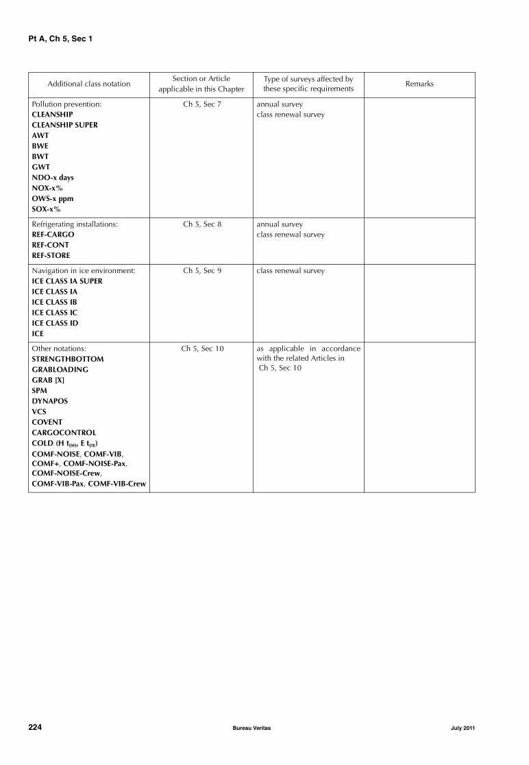
Pt A, Ch 5, Sec 1
Pollution prevention:CLEANSHIPCLEANSHIP SUPERAWTBWEBWTGWTNDO-x daysNOX-x%OWS-x ppmSOX-x%
Ch 5, Sec 7 annual surveyclass renewal survey
Refrigerating installations:REF-CARGOREF-CONTREF-STORE
Ch 5, Sec 8 annual surveyclass renewal survey
Navigation in ice environment:ICE CLASS IA SUPERICE CLASS IAICE CLASS IBICE CLASS ICICE CLASS IDICE
Ch 5, Sec 9 class renewal survey
Other notations:STRENGTHBOTTOMGRABLOADINGGRAB [X]SPMDYNAPOSVCSCOVENTCARGOCONTROLCOLD (H tDH, E tDE)COMF-NOISE, COMF-VIB, COMF+, COMF-NOISE-Pax, COMF-NOISE-Crew, COMF-VIB-Pax, COMF-VIB-Crew
Ch 5, Sec 10 as applicable in accordancewith the related Articles in Ch 5, Sec 10
Additional class notationSection or Article
applicable in this ChapterType of surveys affected by these specific requirements
Remarks
224 Bureau Veritas July 2011

Pt A, Ch 5, Sec 2
SECTION 2 VERISTAR AND STAR NOTATIONS
1 General
1.1 Application
1.1.1 The requirements of this Section apply to ships whichhave been assigned one of the following additional classnotations related to the VeriSTAR system, as described inCh 1, Sec 2, [6.2]:
STAR-HULL
VeriSTAR-HULL SIS
STAR-MACH SIS
2 VeriSTAR-HULL SIS
2.1 General
2.1.1 As indicated in Pt E, Ch 1, Sec 1, the additional classnotation VeriSTAR-HULL SIS is assigned at the design stageor after construction, and maintained during the service life,to ships complying with the requirements of Ch 1, Sec 2,[6.2.2].
2.1.2 The additional class notation VeriSTAR-HULL SIS isassigned to a ship in order to reflect the following:
• a structural tridimensional analysis has been performedfor the hull structures, as defined in Pt B, Ch 7, App 1 orPt B, Ch 7, App 2 or Pt B, Ch 7, App 3, as applicable
• the hull structure condition is periodically assessed,usually at the class renewal survey, using the results ofthe inspections and thickness measurements performedduring the survey. The results of this assessment is madeavailable to the Owner.
2.1.3 The following is to be available on board:
• the class renewal survey report
• the results of the periodical structural reassessmentsdone after each class renewal survey
• the Society’s requirements for structural repairs andrenewals
• the hot spot map of the structure.
2.2 Class renewal survey
2.2.1 The survey for the renewal of the VeriSTAR-HULL SISnotation is to be carried out concurrently with the classrenewal survey.
The documentation to be prepared, the surveys to be car-ried out and the structural reassessment to be done in con-nection with the class renewal survey are summarized inthe flowchart shown in Fig 1.
2.2.2 In addition to the scope of the class renewal survey asrequired for the ship concerned, additional thickness meas-urements and surveys may be required by the Society takinginto account the surveys, thickness measurements and aspecific survey for fatigue fracture detection carried out as aresult of the previous hot spot map.
2.2.3 On the basis of the results of the surveys, thicknessmeasurements and fatigue fracture detection carried out asindicated in [2.2.2], the “as-inspected state” of the ship isestablished. A structural reassessment of the “as-inspectedstate” is performed according to the acceptance criteriabased on Ch 2, App 3 or Pt E, Ch 1, App 2 for items asdeemed appropriate by the Society. This state may be pro-gressively updated based on the results of additional sur-veys and/or thickness measurements required on the basisof the first run of the analysis.
The Owner then defines a program of structural renewalsand repairs using the indications of the final “as-inspectedstate”.
2.2.4 Once repairs and renewals are completed to theSociety satisfaction, a new “as-repaired state” of the ship isobtained, including an updated hot spot map.
3 STAR-HULL
3.1 General
3.1.1 As indicated in Pt E, Ch 1, Sec 2, the additional classnotation STAR-HULL is assigned to a ship in order to reflectthe fact that a procedure including periodical and correc-tive maintenance, as well as periodical and occasionalinspections of hull structures and equipment, (hereafterreferred to as the Inspection and Maintenance Plan - IMP)are dealt with on board by the crew and at the Owner’soffices according to approved procedures.
The assignment of the notation implies that a structural tridi-mensional analysis has been performed for the hull struc-tures, as defined in Pt B, Ch 7, App 1 or Pt B, Ch 7, App 2 orPt B, Ch 7, App 3, as applicable.
The implementation of the Inspection and MaintenancePlan is surveyed by the Society through:
• periodical check of the hull structure, normally at theclass renewal survey, against defined acceptance crite-ria and based on:
- the collected data from actual implementation of theInspection and Maintenance Plan
- the results of the inspections, thickness measure-ments and other checks carried out during the classrenewal survey.
July 2011 Bureau Veritas 225
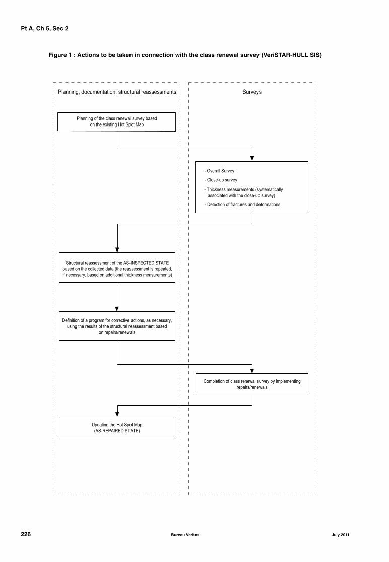
Pt A, Ch 5, Sec 2
Figure 1 : Actions to be taken in connection with the class renewal survey (VeriSTAR-HULL SIS)
�������� � �� ���� ������� ������ �����
�� �� ������� �� ��� ���
� ������� ������
� �������� ������
� ��� ����� ������ ��� !���� �� ����
���� ���� ��� �� ������� ������"
� #�� ��� � �� ���� ��� ���� �����
��� ���� �������� �� � �� $��%&��'��'# ��$�'
����� �� �� ���� �� ��� !�� �������� �� �� �������(
� �� ������( ����� �� ��������� �� ����� ������ ���"
#������� � � ������ �� ���� ��� � ����( �� �� ������(
����� �� ������ � �� ��� ���� �������� �� �����
�� �������)��������
�� ������ � ���� ������� ������ �� � ��� �����
�������)��������
*������ �� �� ��� ���
!$��+'�$%+'# ��$�'"
��������( �� � ������( ��� ���� �������� ��� �������
226 Bureau Veritas July 2011

Pt A, Ch 5, Sec 2
3.2 Class renewal survey
3.2.1 In addition to the scope of the class renewal survey asrequired for the ship concerned (see Fig 2), the following isto be carried out:
• the assessment of the condition of coating and anodes
• additional thickness measurements and surveys may berequired by the Society
• a specific survey for fatigue fracture detection as a resultof the previous hot spot map.
3.2.2 On the basis of the results of the assessment, surveys,thickness measurements and fatigue fracture detection car-ried out as indicated in [3.2.1], the “as-inspected state” ofthe ship is established. A structural reassessment of the “as-inspected state” is performed according to the criteria in Ch2, App 3 Pt E, Ch 1, App 2 for items as deemed appropriateby the Society. This state may be progressively updatedbased on the results of additional surveys and/or thicknessmeasurements required on the basis of the first run of theanalysis.
The Owner then defines a program of:
• structural renewals and repairs
• renewals and repair of coating and anodes,
using the indications of the final “as-inspected state”.
In order to ensure that the ship continues to comply withthe acceptance criteria given in Pt E, Ch 1, Sec 2, [4]. Inaddition, the IMP may be modified if needed.
3.2.3 Once repairs and renewals are completed to theSociety satisfaction, a new “as-repaired state” of the ship isobtained, including an updated hot spot map
3.3 Suspension and withdrawal of the notation
3.3.1 The maintenance of the STAR-HULL notation is sub-ject to the same principles as those for the maintenance ofclass: surveys are to be carried out by their limit dates andpossible recommendations (related to the notation) are tobe dealt with by their limit dates.
The suspension of class automatically causes the suspen-sion of the STAR-HULL notation.
3.3.2 Various events may lead either to imposition of a rec-ommendation related to the STAR-HULL notation or to sus-pension of the notation itself. Some cases are given below.
• The condition of the ship is below the minimum levelrequired for class (e.g. scantling of a hull structurebelow the corrosion margin). The action to be taken iseither the immediate repair or the imposition of a rec-ommendation for the class (if acceptable) and suspen-sion of the STAR-HULL notation. However, in caseswhere the recommendation is of a minor nature, thenotation may not be suspended.
• The condition of the ship is below the minimum levelfor the STAR-HULL notation, but still above the level forthe class (e.g. the scantling of a hull structure is belowthe corrosion margin acceptable for the notation but isstill above the corrosion margin). The action to be taken
is either the immediate repair or the imposition of a rec-ommendation for the STAR-HULL notation (without rec-ommendation for class).
• The Inspection and Maintenance Plan is not compliedwith (e.g. delays in performing the operations pro-grammed according to the plan or the scope of inspec-tion and/or maintenance not completely fulfilled).
The action to be taken is:
- either the immediate compliance with the require-ments or the imposition of a recommendation if thenon-conformity is of a minor nature or is an excep-tional occurrence
- or the suspension of the STAR-HULL notation if thenon-conformity is of a major nature or a recurrence.
• A defect or a deficiency is found in applying the IMP.The actions to be taken are the same as stated both forrepair of structure/coating/equipment (first two casesabove) and for the application of the IMP (third caseabove).
• An unexpected defect or deficiency is found or an acci-dent occurs, i.e. not as a result of lack of maintenanceor failure in the application of the IMP. The actions to betaken are the same as stated for repair of structure/coat-ing/equipment (first two cases above).
3.3.3 The withdrawal of the STAR-HULL notation may bedecided in different cases, such as:
• recurrent suspension of the STAR-HULL notation
• suspension of the STAR-HULL notation for more than agiven period (i.e. 3 months)
• expiry or withdrawal of class.
4 STAR-MACH SIS
4.1 General
4.1.1 The additional class notation STAR-MACH SIS, asdescribed in Ch 1, Sec 2, [6.2.6], is assigned as per therequirements of Pt E, Ch 1, Sec 3. The present Article givesrequirements for the maintenance of this notation.
4.2 Annual audit and confirmatory surveys
4.2.1 The annual shipboard audit and confirmatory surveysare to be carried out in conjunction with the annual surveyand in accordance with the requirements of Ch 2, App 1,[5.2].
The scope of this audit and of the confirmatory surveys is toinclude the ship’s items which are covered by the notation,as per Pt E, Ch 1, Sec 3, [2.1.2], in addition to the PMSmachinery items.
4.3 Risk analysis update
4.3.1 The Owner is to submit the equipment data to theSociety once in each five year class period.
A risk analysis update is to be carried out by the Society onthe basis of the above submitted data.
July 2011 Bureau Veritas 227
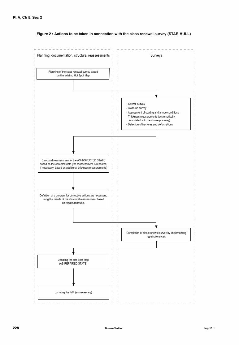
Pt A, Ch 5, Sec 2
Figure 2 : Actions to be taken in connection with the class renewal survey (STAR-HULL)
�������� � �� ���� ������� ������ �����
�� �� ������� �� ��� ���
� ������� ������
� �������� ������
� ��� ����� ������ ��� !���� �� ����
���� ���� ��� �� ������� ������"
� #�� ��� � �� ���� ��� ���� �����
��� ���� �������� �� � �� $��%&��'��'# ��$�'
����� �� �� ���� �� ��� !�� �������� �� �� �������(
� �� ������( ����� �� ��������� �� ����� ������ ���"
#������� � � ������ �� ���� ��� � ����( �� �� ������(
����� �� ������ � �� ��� ���� �������� �� �����
�� �������)��������
�� ������ � ���� ������� ������ �� � ��� �����
�������)��������
*������ �� �� ��� ���
!$��+'�$%+'# ��$�'"
��������( �� � ������( ��� ���� �������� ��� �������
� $����� �� � ����� ��� ����� ��������
*������ �� %�� !�� �� ������"
228 Bureau Veritas July 2011
Pt A, Ch 5, Sec 3
July 2011 Bureau Veritas 229
SECTION 3 AVAILABILITY OF MACHINERY
1 General
1.1
1.1.1 The requirements of this Section apply to ships whichhave been assigned one of the following additional classnotations related to availability of machinery, as describedin Ch 1, Sec 2, [6.3]:AVM-APS
AVM-DPS
AVM-IPS
2 Annual survey
2.1
2.1.1 At each annual survey the Owner or his representa-tive is to declare to the attending Surveyor that no modifica-tions have been made to the systems affecting the notationswithout prior approval by the Society.
3 Class renewal survey
3.1
3.1.1 At each class renewal survey a test is to be conductedin order to ascertain that the systems affecting the notationsoperate satisfactorily. This test is usually to be carried outduring sea trials.

Pt A, Ch 5, Sec 4
230 Bureau Veritas July 2011
SECTION 4 AUTOMATED MACHINERY SYSTEMS
1 General
1.1
1.1.1 The requirements of this Section apply to ships whichhave been assigned one of the following additional classnotations related to automated machinery systems, asdescribed in Ch 1, Sec 2, [6.4]:AUT-UMS
AUT-CCS
AUT-PORT
AUT-IMS
2 Annual survey
2.1
2.1.1 The Owner or his representative is to declare to theattending Surveyor that no significant modifications havebeen made without prior approval by the Society.
2.1.2 The annual survey is to include:• an examination of the engineers’ log-book to verify the
proper operation of automation systems in the periodsubsequent to the last survey and measures taken toavoid repetition of any malfunctions or failures whichhave occurred during the same period
• a general examination of the control systems covered bythe notation, including a random check of the properoperation and calibration of main measuring, monitor-ing, alarm, and automatic shut-off devices
• a check of the fire detectors
• a check of the bilge flooding alarms
• a running test which may be also performed by a spotcheck method.
3 Class renewal survey
3.1
3.1.1 The requirements given in [2] for annual survey are tobe complied with.
An additional program of examinations, checks and tests isto be devised in agreement with the Owner and based onthe operational data and experience of previous surveys.This program is to include verification of the calibration ofinstruments, testing of control and safety functions of themachinery and black-out test. The Owner is to produce evi-dence that all these checks and tests have been carried outand this will be verified by the Surveyor at random.
In addition, the proper operation of the control system ofpropulsion machinery is to be checked during sea trials.
Pt A, Ch 5, Sec 5
SECTION 5 INTEGRATED SHIP SYSTEMS
1 General
1.1
1.1.1 The requirements of this Section apply to ships whichhave been assigned one of the following additional classnotations related to integrated ship systems, as described inCh 1, Sec 2, [6.5]:
SYS-NEQ
SYS-NEQ-1
SYS-COM
SYS-IBS
SYS-IBS-1
2 Annual survey
2.1 All notations
2.1.1 The Owner or his representative is to declare to theattending Surveyor that no significant modifications havebeen made to the relevant installations without the priorapproval by the Society.
An examination of the log-books is to be carried out to ver-ify the proper operation of systems in the period subsequentto the last survey and measures taken to avoid repetition ofany malfunctions or failures which have occurred duringthe same period.
2.2 Notations SYS-NEQ and SYS-NEQ-1
2.2.1 The annual survey is to include:
a) general:
• general examination of the bridge layout, withregard to the field of vision, window wipe and washsystem, wheelhouse lighting and heating/coolingsystems, and arrangements for the safety of naviga-tors
b) propulsion and steering controls:
• test of the steering gear to confirm the proper opera-tion of the various remote controls from the wheel-house
• test, as far as practicable, of the propulsion control,including propeller pitch control, where fitted
• check of the relevant indicators such as rudderangle, ahead/astern position, propeller rpm or pitch
c) navigation aids:
• test of the satisfactory operating condition of radars
• test of the functions available at quay side of theARPA and collision avoidance system
• test of the position fixing system
• test of the gyro compass system
• test of the echo sounding device, using appropriatescale of depth
• test of other available alarms (sounding equipment,self-checking device, etc.), as far as practicable
d) communications:
• test of the whistle control device from the relevantworkstation
• check of the different communication systems (inter-nal communication, VHF radiotelephone installation,NAVTEX)
e) bridge safety and alarm system (notation SYS-NEQ-1)
• test, as far as practicable, of the vigilance system andrelated alarm/warning transfer system.
2.3 Notation SYS-COM
2.3.1 The annual survey is to include a check of the meansof transmission (hardware and software) as follows:
a) compliance of the environmental conditions of use ofthe components (such as temperature, power supply)with those for which they were approved
b) verification of the correct installation on board, includ-ing hardware (cabling, location of aerial, layout of con-sole) and software (such as compatibility of assembledsoftware, man machine interface)
c) verification by means of an appropriate test of theproper function of:
• the internal communication between the differentworkstations, checking at random the availability ofdata
• the external communication with the shore; consid-eration may be given to recent records of such exter-nal communication from ship to shore and fromshore to ship.
July 2011 Bureau Veritas 231

Pt A, Ch 5, Sec 5
2.4 Notations SYS-IBS and SYS-IBS-1
2.4.1 The annual survey is to include a check of the condi-tion of the different workstations that belong to the IBS sys-tem, and a test, as far as practicable, of:
• the main functions of the IBS; in this respect, the exami-nations and tests given in [2.2.1] are to be carried out,where applicable
• the transitional and emergency sources required for thesystem and recovery of systems after restoring power
• the alarm and monitoring system in the wheelhouse, atrandom.
3 Class renewal survey
3.1 All notations
3.1.1 The requirements given in [2] for annual survey are tobe complied with. An additional program of examinations,checks and tests is to be devised in agreement with theOwner and based on the operational data and experience ofprevious surveys. This program is to include verification of thecalibration of instruments and testing of control and safetyfunctions of the installation. An additional program of randomtests of the systems is to be performed during sea trials.The Owner is to confirm that any modification to the hard-ware and software is fully documented and properlyrecorded.
232 Bureau Veritas July 2011
Pt A, Ch 5, Sec 6
July 2011 Bureau Veritas 233
SECTION 6 MONITORING EQUIPMENT
1 General
1.1 Application
1.1.1 The requirements of this Section apply to ships whichhave been assigned one of the following additional classnotations related to hull and tailshaft monitoring equip-ment, as described in Ch 1, Sec 2, [6.6]:MON-HULL
MON-SHAFT
2 MON-HULL
2.1 Annual and class renewal survey
2.1.1 The Owner or his representative is to declare to theattending Surveyor that the hull monitoring equipment hasbeen recently calibrated using a reference loading case.
3 MON-SHAFT
3.1 Tailshaft survey
3.1.1 When the records of the tailshaft bearing temperaturereadings are checked and doubts arise, the Surveyor mayrequire the verification of the accuracy of the gaugingdevices.
Pt A, Ch 5, Sec 7
SECTION 7 POLLUTION PREVENTION
1 General
1.1 Application
1.1.1 The requirements of this Section apply to ships whichhave been assigned one of the following additional classnotations related to pollution prevention systems, asdescribed in Ch 1, Sec 2, [6.8]:
• CLEANSHIP
• CLEANSHIP SUPER
• AWT
• BWE
• BWT
• GWT
• NDO-x days
• NOX-x%
• OWS-x ppm
• SOX-x%
2 Prevention of sea pollution
2.1 First annual survey
2.1.1 Confirmation of no discharge period
During the first annual survey, the Surveyor collects theresults of tests and measurements undertaken by the Ship-owner according to Pt E, Ch 9, Sec 3. These results are usedto confirm or modify the no discharge numeral appended tothe notations NDO-x days.
2.1.2 Audit
An on-board audit of the procedures, as required in Part E,Chapter 9, is done by the Surveyor in order to ascertain thatthe Master and crew are familiar with the ship's on-boardprocedures for preventing pollution and in order to checkthat the discharge records mentioned in Part E, Chapter 9are properly completed.
2.2 Annual survey
2.2.1 General
The survey is to include, as far as practicable:
• confirmation of the installation being in accordancewith the plans. If modifications have been made, check-ing that these modifications are in accordance withapproved documentation (for all additional class nota-tions related to pollution prevention systems)
• confirmation that the IOPP certificate is valid (forCLEANSHIP, CLEANSHIP SUPER and OWS-x ppm)
• general examination of the most important componentsof the sewage treatment plant, the garbage treatmentplant, the oil filtering equipment, the incinerators if fit-ted, the comminuters and grinders, the hazardouswastes recovery unit if fitted (for CLEANSHIP andCLEANSHIP SUPER)
• general examination of the holding tanks, includingexamination of a possible corrosion protection of theinside surfaces of the tanks which are to be in good con-dition (for CLEANSHIP and CLEANSHIP SUPER)
• verification of the satisfactory condition of the standarddischarge connections for oil and wastewater (forCLEANSHIP, CLEANSHIP SUPER, AWT and NDO-xdays)
• external examination and operating tests of the equipementand systems as required in Pt E, Ch 9, Sec 2 and Pt E, Ch9, Sec 3 (for all additional class notations related to pol-lution prevention systems).
• confirmation that the hazardous wastes are properlystowed as specified in the garbage management plan(for CLEANSHIP, CLEANSHIP SUPER and NDO-x days).
For some pollution prevention system of [1.1.1], the surveyis also to include, as far as practicable:
• ascertainment of the correct concentration of the disin-fectant in the effluent (for CLEANSHIP, CLEANSHIPSUPER, AWT and GWT)
• ascertainment of possible concentration of other chemi-cals in the effluent (for CLEANSHIP, CLEANSHIPSUPER, AWT and GWT).
2.2.2 Review of records
The following records for the preceding 12 months are to bereviewed as necessary:
• oil record book (for CLEANSHIP, CLEANSHIP SUPERand OWS-x ppm)
• garbage record book (for CLEANSHIP, CLEANSHIPSUPER and OWS-x ppm)
• records of ballast exchanges after international voyages(for BWE and BWT)
• ballast water record book (for BWE and BWT)
• sewage and grey water discharge book (for CLEANSHIP,CLEANSHIP SUPER, GWT and AWT)
• emissions record (for CLEANSHIP SUPER, NOX-x% andSOX-x%)
• results of the tests on effluents done by the Shipowneraccording to Pt E, Ch 9, Sec 4, [2.3.1] for any pollutionprevention system of [1.1.1] (for AWT).
234 Bureau Veritas July 2011
Pt A, Ch 5, Sec 7
2.3 Class renewal survey
2.3.1 The requirements given in [2.2] for annual surveysare to be complied with. In addition, for all additional classnotations related to pollution prevention systems, the fol-lowing is to be carried out:
• demonstration, under working conditions, of the correctfunctions of the most important components of the sew-age treatment plant or AWT plant if fitted, the garbagetreatment plant, the oil filtering equipment, the incinera-tors if fitted, the comminuters and grinders, the hazard-ous waste recovery unit if fitted
• ascertainment of the correct function of the alarms.
3 Prevention of air pollution
3.1 Annual survey
3.1.1 Ozone depleting substances (CLEANSHIP, CLEANSHIP SUPER)
a) A procedure for annual verification of the system andequipment condition by an authorised organisation is tobe settled. The interval of this verification may beextended in case of predictive maintenance schemeapproved by the Society.
b) A procedure for weekly verification and maintenance isto be settled enabling to:
• check the tightness of the circuits by satisfactorymeans (such as weighing or vessel pressure monitor-ing)
• identify the location of possible leakage
• carry out necessary corrective actions.
Record books tracing all the operations carried out onboard the ship according to the procedures mentionedin the NOx Technical Code are to be kept on-board andupdated after each intervention. They are to include inparticular the following records:
• presence of leak and corrective action
• volume of substance recovered and indication of thestorage location
• volume of substance recharged
• volume of substance consumed
• volume of substance disposed.
The survey is to include the following items:
• verification that the above procedures for annualand weekly checking of systems with ozone deplet-ing substances are available on-board
• confirmation that appropriate entries are beingmade in the record book for ozone depleting sub-stances
• test of the proper operation of the leak detectors andrelated audible and visual alarms
c) Review of ozone - depleting substance record book.
3.1.2 NOx emission (CLEANSHIP SUPER, NOX-x%)
• The procedures for demonstrating compliance withNOx emission limits on board are given in the NOxTechnical Code.
• During the annual survey, it is to be confirmed that theNOx emission control procedure is available on-board
• NOx emission records.
3.1.3 SOx emission (CLEANSHIP, CLEANSHIP SUPER, SOX-x%)
Procedures are to be established to detail the maximum sul-phur content in the fuel oil purchase orders, and to checkthe actual content of sulphur at the delivery of bunker.
In the case the actual sulphur content is checked by sam-pling testing and analysis, procedures are to be carried outin accordance with a recognised standard acceptable to theSociety.
The fuel management procedures are to be established andfollowed as part of the certified ship management system ofthe ship.
Records on purchase orders and on type of checking carriedout, including results, are to be kept on-board.
The survey is to include the following items:
• verification that the above procedures for defining,ordering and checking fuel oils for control of SOx emis-sion are available on-board
• confirmation that fuel oil sulphur content records areavailable on-board
• emission record (when exhaust gas cleaning is provided(EGC)).
3.1.4 Shipboard incineration (CLEANSHIP, CLEANSHIP SUPER)
The annual survey is to include the following items, whenfitted:
• external examination of the incinerators and confirma-tion that such equipment operates satisfactorily
• test of the alarms, exhaust monitoring devices andemergency stop located outside the compartment.
3.2 Class renewal survey
3.2.1 The requirements given in [3.1] for annual surveysare to be complied with. In addition, the following is to becarried out:
• confirmation of the operation and calibration of theemissions analysers if fitted (for CLEANSHIP SUPER,NOX-x% and SOX-x%)
• external examination and operating tests of the equip-ment and systems, as required in Pt E, Ch 9, Sec 2 andPt E, Ch 9, Sec 3 (for all additional class notationsrelated to pollution prevention systems).
July 2011 Bureau Veritas 235
Pt A, Ch 5, Sec 8
SECTION 8 REFRIGERATING INSTALLATIONS
1 General
1.1
1.1.1 The requirements of this Section apply to ships whichhave been assigned one of the following additional classnotations related to refrigerating installations, as describedin Ch 1, Sec 2, [6.9]:
REF-CARGO
REF-CONT
REF-STORE
as well as the following specific notations:
-PRECOOLING
-QUICKFREEZE
-AIRCONT
2 Annual survey
2.1 General
2.1.1 The annual survey of refrigerating installations (plantsand spaces) is to be carried out with the installation in run-ning condition and, whenever possible, during unloadingoperations or without cargo in refrigerated spaces.
2.1.2 The refrigeration installation log-book (or other simi-lar record) is to be made available to the Surveyor for exam-ination of the records since the last survey, and checkingany unusual consumption of refrigerant, breakdown ordefective items.
2.1.3 Decks, bulkheads or ship sides adjacent to refriger-ated spaces are to be checked as far as practicable in orderto verify the absence of cold spots.
2.1.4 The Owner or his representative is to declare to theattending Surveyor that no significant modifications havebeen made to the installations that could affect the classnotations without the prior approval by the Society.
2.2 Refrigerating plant
2.2.1 Refrigerating machines and related accessories,including compressors, condensers, pumps and piping areto be examined externally and in running condition. Insula-tion of insulated parts is to be checked for possible signs ofhumidity or wear. The tightness of the system is to be ascer-tained.
2.2.2 The electrical installation is to be generally exam-ined, and the insulation resistance of the installation is to bechecked as deemed necessary by the Surveyor.
2.2.3 If independent from the electrical installation of theship, the generators supplying electrical power to the refrig-erating installation are to be examined to the same extent asdescribed in Ch 3, Sec 1, [3.3].
2.3 Refrigerated spaces
2.3.1 Refrigerated spaces are to be generally examined toascertain the condition of:
• insulation lining; removable panels or covers may bedismantled for examination of insulation, as deemednecessary by the Surveyor
• hatch covers, doors, access panels (including gasketsand securing devices) and dampers of ventilation ducts
• air coils, coolers, fans, air ducts, brine piping systemsand associated equipment; cleanliness of grids
• bilge wells
• protection of fans and other rotating machinery, battensfor air circulation within the space.
2.4 Instrumentation and safety devices
2.4.1 Thermometers used for measurement of temperaturein refrigerated spaces, air ducts and other elements of theinstallation are to be examined and checked for their accu-racy. The Surveyor may require the calibration of one ormore thermometers and one or more automation devices tobe checked in his presence or, failing this, a certificate ofcalibration is to be presented to him.
2.4.2 The following alarm and safety devices are also to bechecked, as required or fitted:
• alarm and emergency shutdown devices
• CO2 detectors, if any
• refrigerant leakage detectors
• access to spaces, with regard to possibilities of escapeand prevention of personnel being trapped withinspaces.
2.5 Notation -AIRCONT
2.5.1 The requirements of this item apply to installationsassigned the notation -AIRCONT. They are additional to therequirements given in [2.1] to [2.4].
236 Bureau Veritas July 2011
Pt A, Ch 5, Sec 8
2.5.2 The installation is to be visually examined and testedto verify that the controlled atmosphere system remains sat-isfactory. The survey is to include the following items:
• examination of voyage logs, records of controlled atmos-phere zone air-tightness and calibration of instruments
• confirmation that an operating and safety manual isavailable on board, complete and duly endorsed by theofficers responsible
• examination of controlled atmosphere zone sealingarrangements including cleats and hinges, pressure/vac-uum valves, door locks, ventilation of adjacent spaces,warning notices
• test to design pressure of controlled atmosphere zonesfor air-tightness. Tests by ship's staff within one monthprior to the survey may be accepted, based on a writtenreport by the Master subject to visual inspection con-firming the air-tightness.
• operation and performance test of the gas supply equip-ment, including controls, alarms, interlocks and safetydevices
• examination and test of ventilation arrangementsincluding fans as deemed necessary
• examination of electrical supply arrangements
• check of gas analysers, analysing equipment and cali-bration
• check of relative humidity sensors and calibration
• check of permanent and portable gas monitoring, includ-ing calibration, and of personnel safety equipment.
3 Class renewal survey
3.1 General
3.1.1 The installation is to be surveyed out of operation inorder to enable examinations in opened condition of cer-tain items.
3.1.2 After completion of these examinations, the installa-tion is to be checked while cooling down from the ambienttemperature to the lowest design temperature for the refrig-erated spaces. The plant is to be examined for ability tomaintain stable air temperatures and defrosting operation isto be checked.
3.2 Refrigerating plant
3.2.1 The equipment is to be dismantled to a sufficientextent to enable the following examinations:• reciprocating compressors: examination of cylinders,
valves, crankshaft, connecting rods, pistons, bearingsand safety devices
• screw compressors, turbo compressors and pumps:parts subject to wear and tear; the equipment may notneed to be opened up if log-book records and a runningtest show proper functioning.
3.2.2 Prime movers of pumps, compressors and fans are tobe examined to the same extent as required in Ch 3, Sec 3,[3] for similar equipment for the class renewal survey ofmachinery.
3.2.3 Condensers and coolers are to be opened up forexamination of tube plates, tubes and end covers.
Condensers are to be pressure tested to 1,2 times the ratedworking pressure.
3.2.4 Insulation of insulated parts (such as piping and pres-sure vessels) may need to be removed at random, to ascer-tain the condition of such parts and of the insulation itself.
3.2.5 The electrical installation of the plant is to be exam-ined and insulation tests checked.
3.2.6 If independent from the electrical installation of theship, the generators supplying electrical power to the refrig-erating installation are to be examined to the same extent asdescribed in Ch 3, Sec 3, [3.6].
3.2.7 Sea connections to condenser circulating pumps areto be opened up and piping examined.
3.2.8 Other equipment, such as oil separators on refriger-ant systems, filters and dehydrators, are to be examined tothe satisfaction of the Surveyor.
3.3 Refrigerated spaces
3.3.1 The lining and insulation in the refrigerated spacesmay need to be partly removed for examination of its condi-tion. The condition of the hull part under the insulation isthen ascertained, as well as that of girders, meat rails, hooksand coil/cooler supports.
3.3.2 Air coolers and coils are to be examined and pressuretested at the rated working pressure and at 1,2 times suchpressure in the case of hydraulic test after repairs.
3.3.3 Air cooler fans are to be examined and their primemovers are to be checked to the same extent as stated in[3.2.2].
3.3.4 The electrical installation in the refrigerated spaces isto be examined and insulation tests checked.
3.3.5 Defrosting and heating systems are to be examined tothe satisfaction of the Surveyor.
3.4 Instrumentation and safety devices
3.4.1 Pressure relief valves and safety disks are to bechecked. Discharge piping is to be examined with regard tointegrity and non-obstructed flow.
3.5 Notation -AIRCONT
3.5.1 The requirements of this item apply to installationsassigned the notation -AIRCONT. They are additional to therequirements given in [3.1] to [3.4].
3.5.2 Air compressors, pressure vessels and other equip-ment are to be examined to the same extent as required inCh 3, Sec 3, [3] for similar equipment for the class renewalsurvey of machinery.
3.5.3 Each controlled atmosphere zone is to be subjectedto an air-tightness test.
July 2011 Bureau Veritas 237
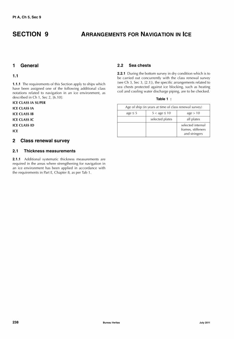
Pt A, Ch 5, Sec 9
238 Bureau Veritas July 2011
SECTION 9 ARRANGEMENTS FOR NAVIGATION IN ICE
1 General
1.1
1.1.1 The requirements of this Section apply to ships whichhave been assigned one of the following additional classnotations related to navigation in an ice environment, asdescribed in Ch 1, Sec 2, [6.10]:ICE CLASS IA SUPER
ICE CLASS IA
ICE CLASS IB
ICE CLASS IC
ICE CLASS ID
ICE
2 Class renewal survey
2.1 Thickness measurements
2.1.1 Additional systematic thickness measurements arerequired in the areas where strengthening for navigation inan ice environment has been applied in accordance withthe requirements in Part E, Chapter 8, as per Tab 1.
2.2 Sea chests
2.2.1 During the bottom survey in dry condition which is tobe carried out concurrently with the class renewal survey(see Ch 3, Sec 3, [2.1]), the specific arrangements related tosea chests protected against ice blocking, such as heatingcoil and cooling water discharge piping, are to be checked.
Table 1 :
Age of ship (in years at time of class renewal survey)
age ≤ 5 5 < age ≤ 10 age > 10
selected plates all plates
selected internal frames, stiffeners
and stringers
Pt A, Ch 5, Sec 10
SECTION 10 OTHER NOTATIONS
1 General
1.1
1.1.1 The requirements of this Section apply to ships whichhave been assigned one of the following additional classnotations described in Ch 1, Sec 2, [6.14]:
STRENGTHBOTTOM
GRABLOADING
GRAB [X]
SPM
DYNAPOS
VCS
COVENT
CARGOCONTROL
COLD (H tDH, E tDE)
COMF-NOISE, COMF-VIB, COMF+, COMF-NOISE-Pax,COMF-NOISE-Crew, COMF-VIB-Pax, COMF-VIB-Crew
2 STRENGTHBOTTOM
2.1 Dry-docking survey
2.1.1 The reinforced area of bottom plating and internalassociated structures are to be visually examined for possi-ble deformations, fractures or other damage. If deemed nec-essary, thickness measurements may be required.
3 GRABLOADING and GRAB[X]
3.1 Class renewal survey
3.1.1 The reinforced area of inner bottom plating, lowerpart of hopper tank sloping plating and transverse lowerstool plating and adjacent associated structures, as applica-ble, are to be visually examined for possible deformations,fractures or other damage. If deemed necessary, thicknessmeasurements may be required.
4 SPM
4.1 Annual survey
4.1.1 The Owner or his representative is to declare to theattending Surveyor that no significant alterations have beenmade without the prior approval of the Society.
4.1.2 The annual survey is to include:
• a general examination of all components of the installa-tion (bow chain stoppers, bow fairleads, pedestal rollerfairleads, winches and capstans) to verify their satisfac-tory condition
• an examination of the hull structures supporting andadjacent to the installation to verify that no deforma-tions or fractures have developed.
4.2 Class renewal survey
4.2.1 The class renewal survey is to include:
• a close-up examination of all components of the instal-lation (bow chain stoppers, bow fairleads, pedestalroller fairleads, winches and capstans) to verify their sat-isfactory condition
• a close-up examination of the hull structures supportingand adjacent to the installation to verify that no defor-mations or fractures have developed.
Where deemed necessary by the Surveyor, non-destructivetests for measuring thickness deterioration or checking forfractures or other defects may be required.
5 DYNAPOS
5.1 Annual survey
5.1.1 The program of the annual survey may be previouslyagreed with the Society.
The Owner or his representative is to declare to the attend-ing Surveyor that no significant alterations have been madewithout the prior approval of the Society.
5.1.2 The annual survey is to include:
• an examination of the log-books to verify the properoperation of systems in the period subsequent to the lastsurvey and measures taken to avoid repetition of anymalfunctions or failures which have occurred during thesame period
• a general examination of visible parts of thrust units,including their prime movers
• a general examination of the electrical power systemand switchboards
• a general examination of control, monitoring and alarmdevices
• a running test of the installation, including random testby simulation of different alarms and relevant backupsystems and switching modes.
July 2011 Bureau Veritas 239
Pt A, Ch 5, Sec 10
5.2 Class renewal survey
5.2.1 In general, the class renewal survey consists of thechecks detailed in [5.2.3] to [5.2.6]. However, a specificprogram of the class renewal survey prepared by the Ownerand taking into account the maintenance procedures of theManufacturers of the system is to be submitted to the Soci-ety prior to the survey.
5.2.2 The Owner is to confirm that any modification to thesoftware is fully documented and properly recorded.
5.2.3 Prime movers of thrust units, electrical installationsand electric power generators are to be surveyed and testedto the same extent as required in Ch 3, Sec 3, [3] for similarequipment for the class renewal survey of machinery.
5.2.4 During the bottom survey in dry condition which is tobe carried out concurrently with the class renewal survey(see Ch 3, Sec 3, [2.1]), the thrust units are to be generallyexamined. Other checks are to be carried out, such as tak-ing clearances, examination of the orientation device orvariable pitch system, if any, verifying tightness devices,examination of results of lube oil analysis for detection ofpossible deterioration of internal gears andbearings. Dismantling of internal parts may be required ifthe above examinations are not satisfactory.
5.2.5 Sensors and position reference systems are to betested to check their accuracy. Failure of sensors is to besimulated in order to check the related alarm system andswitching logic. Switch over to the different reference sys-tems is to be checked.
5.2.6 An operational test of the installation is to be per-formed, including:
• test of each thrust unit at different loads, pitches andspeeds, and check of monitoring devices
• test of the thrust controls in the different availablemodes (automatic, semi-automatic, manual), and theswitch over between the different modes
• test of the different alarms and safety systems, using sim-ulated conditions as necessary
• test of power supply failure and verification of intendedfunctioning in such cases
• final test to verify the capacity of the system to keep theship in the intended position and maintain the heading,with related alarm and monitoring devices. The accu-racy of the system is to be checked and compared withprevious results for evaluation of drift
• test of the power management system.
6 VCS
6.1 Annual survey
6.1.1 The Owner or his representative is to declare to theattending Surveyor that no significant modifications havebeen made without the prior approval of the Society.
6.1.2 The annual survey is to include:
• an examination of the instruction manual to verify thelayout of the complete system and confirm the corre-spondence to the actual system fitted on board
• a general examination of components of the systemsuch as vapour piping (including manifold and hoses),cargo tank gauging equipment, cargo tank level alarms,vapour pressure alarms and vapour balancing, if any, toverify their satisfactory condition.
6.2 Class renewal survey
6.2.1 The requirements given in [6.1] for annual survey areto be complied with. Additionally, the following is to becarried out:
• a pressure test of the vapour piping, including manifoldand hoses
• a check and test of the instrumentation (cargo tankgauging equipment, cargo tank level alarms, vapourpressure alarms)
• an inspection and test of the vapour balancing equip-ment, if any
• a running test of the system.
7 COVENT
7.1 Annual survey
7.1.1 The Owner or his representative is to declare to theattending Surveyor that no significant modifications havebeen made without the prior approval of the Society.
7.1.2 The annual survey is to include a general examina-tion of components of the system such as ventilation pipingand fans.
7.2 Class renewal survey
7.2.1 The requirements given in [7.1] for annual survey areto be complied with. Additionally, the following is to becarried out:
• an inspection of the components of the system to thesame extent as required in Ch 3, Sec 3, [3] for similarequipment for the class renewal survey of machinery
• a running test of the system.
8 CARGOCONTROL
8.1 Annual survey
8.1.1 The Owner or his representative is to declare to theattending Surveyor that no significant modifications havebeen made without the prior approval of the Society.
240 Bureau Veritas July 2011

Pt A, Ch 5, Sec 10
8.1.2 The annual survey is to include:
• a general examination of the items of equipment regard-ing remote control of operations and gauging/alarmsprovided for all those parameters that are required to bekept under control to verify their satisfactory condition
• a running test which may be also performed by a spotcheck method.
8.2 Class renewal survey
8.2.1 The requirements given in [8.1] for annual survey areto be complied with. Additionally, the following is to becarried out:
• a check and test of the instrumentation fitted to the com-ponents of the system
• an overall running test of the system.
9 COLD (H tDH, E tDE)
9.1 General
9.1.1 The requirements of this Article apply to ships whichhave been assigned the following additional class notationdefined in Ch 1, Sec 2, [6.14.12]:
COLD (H tDH, E tDE)
9.2 Annual survey
9.2.1 The annual survey is to include:
a) Documentation:
• verification that a manual with procedures for de-icing is available on-board
• verification that the approved stability manual,including loading conditions with ice accretion, isavailable on-board.
b) Electrical installations:
• general external examination of the arrangementsfor heated bridge windows and heated cargo controlroom windows, the de-icing systems for all escapedoors and all main doors giving access to the deckarea, the heating of bunker lines on deck, the heat-ing of scupper lines, the heating of whistle, the heat-ing of antennas and similar equipment
• general external examination of the socket outletsprovided close to each lifeboat to supply the heatingsystem of lifeboat engine
• test of the de-icing systems including indicationsand alarms, at random
• test, as far as practicable, of the sequence of ventila-tion in loop in the air inlet compartment on airintakes for HVAC, machinery room and emergencygenerator room.
c) Machinery installations:
• general external examination and testing at randomof the ventilation system for the machinery compart-ments
• general external examination of de-icing arrange-ments for sea inlets, overboard discharges (above thewater line and up to 1 m below the ballast waterline), air pipes and their automatic closing deviceswhere fitted, sounding pipes and overflow pipes (forcooling water recirculation tanks and water ballasttanks), air vent heads, piping systems in exposedareas including ro-ro spaces, spray water lines,exposed deck scuppers, washing lines and dischargelines
• general examination, as far as practicable, of the de-icing arrangements provided to the water ballasttanks adjacent to the shell plating and located totallyor partly above the ballast water line
• general examination, as far as practicable of the de-icing arrangements provided to other tanks subjectto freezing (such as fresh water, fuel oil tanks)
• general examination of the specific heating arrange-ments provided for the cargo P/V valves
• test of the de-icing systems including indicationsand alarms, at random.
d) Other equipment:
• general external examination of the de-icing systemon the exposed deck to allow the de-icing of theship areas where the crew may have access duringthe normal operation of the ship (manoeuvring area,loading and unloading area, area around the accessto the deckhouses, passageways, gangways, walk-ways)
• general examination of the specific arrangements forprotection of equipment fitted on deck (foam moni-tors, davits, lifeboats, lifejackets lockers, winches,windlasses, cranes, other deck machinery) and ofhelideck and its access
• general examination of personal protection andevacuation equipment which are to be suitable forthe design temperature
• general examination of specific protection fitted oncargo valves and associated instrumentation, such astarpaulins
• general examination of appropriate gratings andstairs (including escapes, access to lifeboats and towinching areas) for facilitation of circulation onexposed decks and of safety lines where provided
• general examination of heating arrangement forhydraulic oil system of deck machinery, where pro-vided
• general examination of arrangements made toensure 20°C in the accommodation and of arrange-ments made to control humidity, for HVAC plant
• verification that sufficient hand tools or similarequipment for manual de-icing operations are avail-able on-board and stored on the main deck at loca-tions protected from accumulation of ice
• general examination of navigation and communica-tion equipment which are to be suitable for thedesign temperature.
July 2011 Bureau Veritas 241
Pt A, Ch 5, Sec 10
9.3 Class renewal survey
9.3.1 The requirements given in [9.2] for annual survey areto be complied with. In addition, a test of the de-icing sys-tems, including indications and alarms, is to be carried out.
10 COMF-NOISE, COMF-VIB, COMF+, COMF-NOISE-Pax, COMF-NOISE-Crew, COMF-VIB-Pax, COMF-VIB-Crew
10.1 General
10.1.1 The Owner is to inform the Society in order to sub-mit the ship to a survey so as to maintain the additionalclass notations after modifications, alterations or repairswhich could affect the noise and vibration environmenthave occurred.
10.2 Annual survey
10.2.1 The Owner or his representative is to declare to theattending Surveyor that no significant modifications havebeen made without the prior approval of the Society, in par-ticular with respect to: • modifications/repairs carried out in crew or passenger
accommodations• HVAC/duct routing modifications• machinery modifications, main repairs• list of any alterations, repairs or damages.
10.3 Class renewal survey
10.3.1 The general wear of the ship can induce vibrationand noise increase. A survey including noise measurementsin harbour and sea conditions, insulation and impact noisemeasurements has to be carried out.Measurements can be limited to 30% of initial survey meas-uring points.
242 Bureau Veritas July 2011
Part AClassification and Surveys
Chapter 6
RETROACTIVE REQUIREMENTSFOR EXISTING SHIPS
SECTION 1 GENERAL
SECTION 2 BULK CARRIERS, ORE CARRIERS AND COMBINATION CARRIERS
SECTION 3 RO-RO PASSENGER SHIPS
SECTION 4 CARGO SHIPS
SECTION 5 SHIPS WITH ICE CLASSES
APPENDIX 1 TECHNICAL RETROACTIVE REQUIREMENTS FOR BULK CARRIERS AND OTHER TYPES O SHIPS
July 2011 Bureau Veritas 243

244 Bureau Veritas July 2011

Pt A, Ch 6, Sec 1
July 2011 Bureau Veritas 245
SECTION 1 GENERAL
1 General
1.1
1.1.1 The purpose of this Chapter is to deal with the retro-active rule requirements applicable to existing ships whichderive from the implementation of SOLAS regulations, IACSUnified Requirements or specific regulations from anAdministration.
1.1.2 These requirements are relevant to both constructionfeatures and surveyable items. They are laid down in thefollowing Sections according to the service notationsassigned to ships.
This Chapter also contains an Appendix for ready referencereproducing the text of the retroactive IACS UnifiedRequirements relevant to ships assigned the service notationbulk carrier ESP.
As a rule, requirements related to additional service featuresBC-A, BC-B or BC-C are not applicable to ships having theservice notation bulk carrier ESP contracted for construc-tion before 1st July 2003 or contracted for construction on orafter 1st July 2003 but less than 150 m in length.
1.2 List of retroactive rule requirements
1.2.1 Tab 1 summarises these retroactive requirementsindicating the service notations to which they are applica-ble and in which Section they are given.
Table 1 : Summary of retroactive rule requirements
Service notationSection in Chapter 6
Ship’s survey items or features concerned
bulk carrier ESP Ch 6, Sec 2 - Scantlings of transverse bulkhead between the two foremost cargo holds- Allowable hold loading of the foremost cargo hold- Damage stability- Intermediate survey in lieu of annual survey in the foremost cargo hold- Detection of water ingress into cargo holds- Cargo hatch cover securing arrangements- Renewal criteria for side shell frames and brackets- Restriction from sailing with any hold empty
bulk carrier ESPore carrier ESPcombination carrier/OBO ESP combination carrier/OOC ESP
Ch 6, Sec 2 - Loading conditions, loading manuals and loading instruments- Strength and securing of small hatches on the exposed fore deck- Strength requirements for fore deck fittings and equipment- Hold, ballast and dry space water level detectors- Availability of pumping systems
ro-ro passenger ship Ch 6, Sec 3 - Increased stability and watertight integrity
general cargo shipbulk carrier (without ESP)refrigerated cargo shiplivestock carrier
deck ship
Ch 6, Sec 4 - Strength and securing of small hatches on the exposed fore deck- Strength requirements for fore deck fittings and equipment
ships with Ice Classes Ch 6, Sec 5 - Maintenance of additional class notations ICE CLASS IA SUPER,ICE CLASS IA, ICE CLASS IB, ICE CLASS IC
Pt A, Ch 6, Sec 2
SECTION 2 BULK CARRIERS, ORE CARRIERS AND
COMBINATION CARRIERS
1 Foremost cargo hold requirements
1.1 Application
1.1.1 These retroactive rule requirements apply to shipswith service notation bulk carrier ESP:
• of single side skin construction see [1.1.1], Note 1
• of 150 metres in length and above
• intended to carry solid bulk cargoes having a bulk den-sity of 1,78 t/m3 or above
• contracted for construction prior to 1st July 1998, andnot constructed in compliance with the applicablerequirements for new buildings contracted after thatdate, and given in Pt D, Ch 4, Sec 3.
Note 1: Single side skin bulk carriers means, as defined in SOLASconf. 4/25 Res.6, where one or more cargo holds are bound by theside shell only or by two watertight boundaries, one of which is theside shell, which are less than 760 mm apart in bulk carriers con-structed before 1st January 2000, and less than 1000 mm apart inbulk carriers constructed on or after 1st January 2000. The distancebetween the watertight boundaries is to be measured perpendicularto the side shell (ref.: IMO MSC Res.89(71)).
1.1.2 They are related to:
• scantlings of the transverse corrugated cargo hold bulk-head between the two foremost cargo holds, as detailedin [1.3]
• allowable hold loading of the foremost cargo hold withthe same hold flooded, as detailed in [1.4]
• damage stability with the foremost cargo hold flooded,as detailed in [1.5].
1.1.3 In case where such ships cannot comply to therequirements for damage stability due to their design, thenthe requirements of [1.6] are applicable, instead of thoselaid down in [1.3], [1.4] and [1.5].
1.2 Schedule for compliance
1.2.1 These requirements are to be complied with by thefollowing limit dates:
• for ships which were 20 years of age or more on 1st July1998, by the due date of the first intermediate survey orthe due date of the first class renewal survey, to be heldafter 1st July 1998, whichever comes first
• for ships which were 15 years of age or more, but lessthan 20 years on 1st July 1998, by the due date of thefirst class renewal survey to be held after 1st July 1998,but not later than 1st July 2002
• for ships which were 10 years of age or more, but lessthan 15 years on 1st July 1998, by the due date of the nextintermediate survey or class renewal survey after the dateon which the ship reaches 15 years of age, but not laterthan the date on which the ship reaches 17 years of age
• for ships which were 5 years of age or more, but lessthan 10 years on 1st July 1998, by the due date, after1st July 2003, of the next intermediate survey or classrenewal survey after the date on which the ship reaches10 years of age, whichever occurs first
• for ships which were less than 5 years of age on 1st July1998, by the date on which the ship reaches 10 years ofage.
1.2.2 Completion, prior to 1st July 2003, of an intermediateor class renewal survey with a due date after 1st July 2003,cannot be used to postpone compliance.
However, completion prior to 1st July 2003 of an intermedi-ate survey the window for which straddles 1st July 2003 canbe accepted.
1.3 Scantlings of the vertically corrugated transverse watertight bulkhead between the two foremost cargo holds
1.3.1 The net scantlings of the vertically corrugated trans-verse watertight bulkhead between the two foremost cargoholds are to be assessed in accordance with the methodgiven in Ch 6, App 1, [2].In these requirements, homogeneous loading conditionmeans a loading condition in which the ratio between thehighest and the lowest filling ratio, evaluated for the twoforemost cargo holds, does not exceed 1,20, to be correctedfor different cargo densities.
1.3.2 Thickness measurements are necessary to determinethe general condition of the structure and to define the extentof possible repairs and/or reinforcements of the vertically cor-rugated transverse watertight bulkhead for verification of thecompliance with the requirements given in Ch 6, App 1, [2].Thickness measurements and assessment of the scantlingsare to be carried out for the initial evaluation at the limitdate as defined in [1.2.1], and thereafter at each subsequentintermediate survey (for ships over 10 years of age) andeach subsequent class renewal survey for purposes of veri-fying continuing compliance with the above mentionedrequirements.
1.3.3 Taking into account the buckling criteria applied inCh 6, App 1, [2] in the evaluation of strength of the bulk-head, it is essential to determine the thickness diminution atthe critical levels shown in Fig 1 and Fig 2.
246 Bureau Veritas July 2011
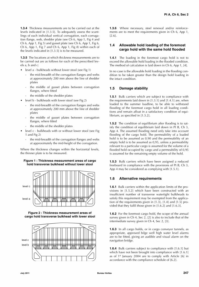
Pt A, Ch 6, Sec 2
1.3.4 Thickness measurements are to be carried out at thelevels indicated in [1.3.5]. To adequately assess the scant-lings of each individual vertical corrugation, each corruga-tion flange, web, shedder plate (see Ch 6, App 1, Fig 4 andCh 6, App 1, Fig 5) and gusset plate (see Ch 6, App 1, Fig 6,Ch 6, App 1, Fig 7 and Ch 6, App 1, Fig 8) within each ofthe levels indicated in [1.3.5] is to be measured.
1.3.5 The locations at which thickness measurements are tobe carried out are as follows for each of the prescribed lev-els a, b and c:
• level a - bulkheads without lower stool (see Fig 1)
- the mid-breadth of the corrugation flanges and websat approximately 200 mm above the line of shedderplates
- the middle of gusset plates between corrugationflanges, where fitted
- the middle of the shedder plates
• level b - bulkheads with lower stool (see Fig 2)
- the mid-breadth of the corrugation flanges and websat approximately 200 mm above the line of shedderplates
- the middle of gusset plates between corrugationflanges, where fitted
- the middle of the shedder plates
• level c - bulkheads with or without lower stool (see Fig1 and Fig 2)
- the mid-breadth of the corrugation flanges and websat approximately the mid-height of the corrugation.
Where the thickness changes within the horizontal levels,the thinner plate is to be measured.
Figure 1 : Thickness measurement areas of cargo hold transverse bulkhead without lower stool
Figure 2 : Thickness measurement areas ofcargo hold transverse bulkhead with lower stool
1.3.6 Where necessary, steel renewal and/or reinforce-ments are to meet the requirements given in Ch 6, App 1,[2.6].
1.4 Allowable hold loading of the foremost cargo hold with the same hold flooded
1.4.1 The loading in the foremost cargo hold is not toexceed the allowable hold loading in the flooded condition.The method of calculation is laid down in Ch 6, App 1, [4].
In no case is the allowable hold loading in the flooding con-dition to be taken greater than the design hold loading inthe intact condition.
1.5 Damage stability
1.5.1 Bulk carriers which are subject to compliance withthe requirements laid down in [1.3.1] and [1.4.1] are, whenloaded to the summer loadline, to be able to withstandflooding of the foremost cargo hold in all loading condi-tions and remain afloat in a satisfactory condition of equi-librium, as specified in [1.5.2].
1.5.2 The condition of equilibrium after flooding is to sat-isfy the condition of equilibrium laid down in Pt B, Ch 3,App 4. The assumed flooding need only take into accountflooding of the cargo hold. The permeability of a loadedhold is to be assumed as 0,90 and the permeability of anempty hold is to be assumed as 0,95, unless a permeabilityrelevant to a particular cargo is assumed for the volume of aflooded hold occupied by cargo and a permeability of 0,95is assumed for the remaining empty volume of the hold.
1.5.3 Bulk carriers which have been assigned a reducedfreeboard in compliance with the provisions of Pt B, Ch 3,App 4 may be considered as complying with [1.5.1].
1.6 Alternative requirements
1.6.1 Bulk carriers within the application limits of the pro-visions in [1.5.2] which have been constructed with aninsufficient number of transverse watertight bulkheads tosatisfy this requirement may be exempted from the applica-tion of the requirements given in [1.3], [1.4] and [1.5] pro-vided that they fulfil those given in [1.6.2] and [1.6.3].
1.6.2 For the foremost cargo hold, the scope of the annualsurvey given in Ch 4, Sec 2, [2] is also to include that of theintermediate survey given in Ch 4, Sec 2, [3].
1.6.3 In all cargo holds, or in cargo conveyor tunnels, asappropriate, approved bilge well high water level alarmsare to be fitted, giving an audible and visual alarm on thenavigation bridge.
1.6.4 Bulk carriers subject to compliance with [1.6.1] butwhich have not been brought into compliance with [1.6.1]as of 1st January 2004 are to comply with Article [6] inaccordance with the compliance schedule of [6.2].
level c
level a
level c
level b
July 2011 Bureau Veritas 247

Pt A, Ch 6, Sec 2
2 Loading instruments and loading manuals
2.1 Loading instruments
2.1.1 Bulk carriers, ore carriers and combination carriers,which are assigned one of the following service notations:
• bulk carrier ESP
• ore carrier ESP
• combination carrier/OBO ESP
• combination carrier/OOC ESP
of 150 m length and above, which were contracted for con-struction before 1st July 1998, are to be provided with anapproved loading instrument of a type to the satisfaction ofthe Society not later than their entry into service or 1st Janu-ary 1999, whichever occurs later.
2.2 Loading manuals
2.2.1 All single side skin bulk carriers which are assignedthe service notation bulk carrier ESP, of 150 m length andabove, which were contracted for construction before1st July 1998 are to be provided before 1st July 1999, or theirentry into service whichever occurs later, with an approvedloading manual with typical loading sequences where theship is loaded from commencement of cargo loading toreaching full deadweight capacity, for homogeneous condi-tions, relevant part load conditions and alternate condi-tions, where applicable. Typical unloading sequences forthese conditions are also to be included.
Guidance for preparation of such loading/unloadingsequences is given in Ch 6, App 1, [7].
3 Strength requirements for fore deck fittings and equipment, strength and securing of small hatches on the exposed fore deck
3.1 Application and requirements
3.1.1 These retroactive rule requirements apply to shipswhich are assigned one of the following service notations:
• bulk carrier ESP
• bulk carrier BC-A ESP
• bulk carrier BC-B ESP
• bulk carrier BC-C ESP
• ore carrier ESP
• combination carrier/OBO ESP
• combination carrier/OOC ESP,
of 100 m in length and above, that are contracted for con-struction prior to 1st January 2004.
3.1.2 These retroactive rule requirements provide strengthrequirements to resist green sea forces for the followingitems located within the forward quarter length: air pipes,ventilator pipes and their closing devices.
They are applicable only for air pipes, ventilator pipes andtheir closing devices on the exposed deck serving spacesforward of the collision bulkhead, and to spaces whichextend over this line aft-wards.
The provisions for compliance with these strength require-ments for fore deck fittings and equipment are given in Pt C,Ch 1, Sec 10, [9.1.9].
These retroactive rule requirements are also applicable forsmall hatches on the exposed deck giving access to spacesforward of the collision bulkhead, and to spaces whichextend over this line aft-wards.
They are related to the strength of, and securing for, suchsmall hatches fitted on the exposed fore deck.
The provisions for compliance with these requirements forstrength and securing of small hatches on the exposed foredeck are given in Pt B, Ch 9, Sec 7, [9].
Note 1:
• small hatches in the context of these retroactive rule require-ments are hatches designed for access to spaces below thedeck and capable to be closed weather-tight or watertight, asapplicable. Their opening is normally 2,5 square meters or less.
• hatches designed for emergency escape need not comply withthe requirements of Pt B, Ch 9, Sec 7, [9.4.1], items a) and b),and of Pt B, Ch 9, Sec 7, [9.4.3] and Pt B, Ch 9, Sec 7, [9.5.1].
Note 2: For ships contracted for construction prior to 1st July 2007,the following is to be carried out:
• securing devices of hatches designed for emergency escape areto be of a quick-acting type (e.g. one action wheel handles areto be provided as central locking devices for latching/unlatchingof hatch cover) operable from both sides of the hatch cover,
by the compliance date specified in [3.2.1] or by the due date of thefirst class renewal survey after 1st July 2007 whichever is later. Com-pletion prior to 1st July 2007 of a class renewal survey with a duedate after 1st July 2007 cannot be used to postpone compliance.
Note 3: These requirements do not apply to the cargo tank ventingsystems and the inert gas systems of tankers.
3.2 Schedule for compliance
3.2.1 Ships referred to in [3.1.1] are to comply with theprovisions of Pt B, Ch 9, Sec 7, [9] and of Pt C, Ch 1, Sec10, [9.1.9] by the following dates:
• for ships which will be 15 years of age or more on1st January 2004, by the due date of the first intermedi-ate or class renewal survey after that date
• for ships which will be 10 years of age or more on1st January 2004, by the due date of the first classrenewal survey after that date
• for ships which will be less than 10 years of age on1st January 2004, by the date on which the ship reaches10 years of age.
3.2.2 Completion, prior to 1st January 2004, of an interme-diate or class renewal survey with a due date after 1st Janu-ary 2004 cannot be used to postpone compliance.However, completion prior to 1st January 2004 of an inter-mediate survey the window for which straddles 1st January2004 can be accepted.
248 Bureau Veritas July 2011

Pt A, Ch 6, Sec 2
4 Cargo hatch cover securing arrangements for bulk carriers
4.1 Application and requirements
4.1.1 These retroactive rule requirements apply to shipswhich are assigned one of the following service notations:
• bulk carrier ESP• bulk carrier BC-A ESP• bulk carrier BC-B ESP• bulk carrier BC-C ESP,
and which were not built in accordance with Pt B, Ch 9,Sec 7, [1] to Pt B, Ch 9, Sec 7, [7] of edition February 2003of the Rules as amended in accordance with November2003 amendments or subsequent editions.
4.1.2 They are related to steel hatch cover securing devicesand stoppers for cargo hold hatchways No 1 and No 2which are wholly or partially within 0,25 L of the fore per-pendicular, except pontoon type hatch cover.
The provisions for compliance with these requirements forcargo hatch cover securing arrangements are given in Ch 6,App 1, [6].
4.2 Schedule for compliance
4.2.1 Ships referred to in [4.1.1] are to comply with theprovisions of Ch 6, App 1, [6] by the following dates:
• for ships which will be 15 years of age or more on1st January 2004, by the due date of the first intermedi-ate or class renewal survey after that date
• for ships which will be 10 years of age or more on1st January 2004, by the due date of the first classrenewal survey after that date
• for ships which will be less than 10 years of age on1st January 2004, by the date on which the ship reaches10 years of age.
4.2.2 Completion, prior to 1st January 2004 of an interme-diate or class renewal survey with a due date after 1st Janu-ary 2004 cannot be used to postpone compliance.However, completion prior to 1st January 2004 of an inter-mediate survey the window for which straddles 1st January2004 can be accepted.
5 Renewal criteria for side shell frames and brackets in single side skin bulk carriers and single side skin OBO carriers
5.1 Application and requirements
5.1.1 These retroactive rule requirements apply to:
• the side shell frames and brackets of cargo holdsbounded by the single side shell of ships with servicenotation bulk carrier ESP constructed with single deck,topside tanks and hopper tanks in cargo spacesintended primarily to carry dry cargo in bulk,
• the side shell frames and brackets of cargo holdsbounded by the single side shell of ships with servicenotation combination carrier/OBO ESP as defined inCh 1, Sec 2, [4.3.4] but of single side skin construction,
which were not built in accordance with the applicablerequirements of Part II, Chapter 8, Section 8-03 of the1st April 1998 edition of the Rules or subsequent editions.
In the case a ship as defined above does not satisfy abovedefinition in one or more holds, the retroactive rule require-ments do not apply to these individual holds.
5.1.2 These requirements define steel renewal criteria orother measures (reinforcement or coating) to be taken forthe webs and flanges of side shell frames and brackets asper the provisions of Ch 6, App 1, [5].
Reinforcing measures of side frames are also defined as perCh 6, App 1, [5.4.2].
Finite element or other numerical analysis or direct calcula-tion procedures cannot be used as an alternative to compli-ance with these requirements, except in cases of unusualside structure arrangements or framing to which theserequirements cannot be directly applied. In such cases, theanalysis criteria and the strength check criteria are to be inaccordance with the Rules of the Society.
5.2 Schedule for compliance
5.2.1 Steel renewal, reinforcement or coating, whererequired in accordance with Ch 6, App 1, [5], is to be car-ried out in accordance with the following schedule and atsubsequent intermediate and class renewal surveys, forships with service notation bulk carrier ESP.
• for ships which will be 15 years of age or more on1st January 2004, by the due date of the first intermedi-ate or class renewal survey after that date
• for ships which will be 10 years of age or more on1st January 2004, by the due date of the first classrenewal survey after that date
• for ships which will be less than 10 years of age on1st January 2004, by the date on which the ship reaches10 years of age.
5.2.2 For ships with service notation bulk carrier ESP, com-pletion, prior to 1st January 2004, of an intermediate or classrenewal survey with a due date after 1st January 2004 can-not be used to postpone compliance. However, completionprior to 1st January 2004 of an intermediate survey the win-dow for which straddles 1st January 2004 can be accepted.
5.2.3 Steel renewal, reinforcement or coating, whererequired in accordance with Ch 6, App 1, [5], is to be car-ried out in accordance with the following schedule and atsubsequent intermediate and class renewal surveys, forships with service notation combination carrier/OBO ESP:
• for ships which will be 15 years of age or more on1st July 2005, by the due date of the first intermediate orclass renewal survey after that date
• for ships which will be 10 years of age or more on1st July 2005, by the due date of the first class renewalsurvey after that date
July 2011 Bureau Veritas 249
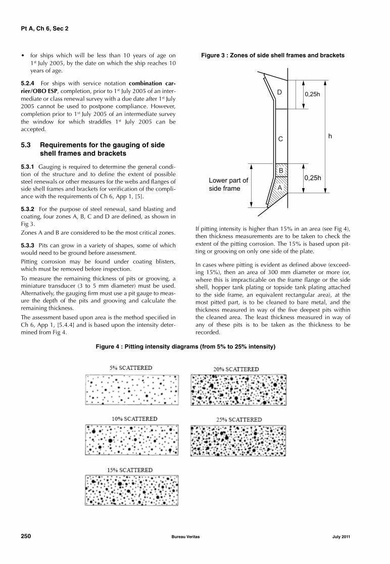
Pt A, Ch 6, Sec 2
• for ships which will be less than 10 years of age on1st July 2005, by the date on which the ship reaches 10years of age.
5.2.4 For ships with service notation combination car-rier/OBO ESP, completion, prior to 1st July 2005 of an inter-mediate or class renewal survey with a due date after 1st July2005 cannot be used to postpone compliance. However,completion prior to 1st July 2005 of an intermediate surveythe window for which straddles 1st July 2005 can beaccepted.
5.3 Requirements for the gauging of side shell frames and brackets
5.3.1 Gauging is required to determine the general condi-tion of the structure and to define the extent of possiblesteel renewals or other measures for the webs and flanges ofside shell frames and brackets for verification of the compli-ance with the requirements of Ch 6, App 1, [5].
5.3.2 For the purpose of steel renewal, sand blasting andcoating, four zones A, B, C and D are defined, as shown inFig 3.Zones A and B are considered to be the most critical zones.
5.3.3 Pits can grow in a variety of shapes, some of whichwould need to be ground before assessment.Pitting corrosion may be found under coating blisters,which must be removed before inspection.
To measure the remaining thickness of pits or grooving, aminiature transducer (3 to 5 mm diameter) must be used.Alternatively, the gauging firm must use a pit gauge to meas-ure the depth of the pits and grooving and calculate theremaining thickness.
The assessment based upon area is the method specified inCh 6, App 1, [5.4.4] and is based upon the intensity deter-mined from Fig 4.
Figure 3 : Zones of side shell frames and brackets
If pitting intensity is higher than 15% in an area (see Fig 4),then thickness measurements are to be taken to check theextent of the pitting corrosion. The 15% is based upon pit-ting or grooving on only one side of the plate.
In cases where pitting is evident as defined above (exceed-ing 15%), then an area of 300 mm diameter or more (or,where this is impracticable on the frame flange or the sideshell, hopper tank plating or topside tank plating attachedto the side frame, an equivalent rectangular area), at themost pitted part, is to be cleaned to bare metal, and thethickness measured in way of the five deepest pits withinthe cleaned area. The least thickness measured in way ofany of these pits is to be taken as the thickness to berecorded.
Figure 4 : Pitting intensity diagrams (from 5% to 25% intensity)
�����
�
�����
�
�
��� ���� �
���� �����
�
�
250 Bureau Veritas July 2011

Pt A, Ch 6, Sec 2
The minimum acceptable remaining thickness in any pit orgroove is equal to:
• 75% of the as-built thickness, for pitting or grooving inthe cargo hold side frame webs and flanges
• 70% of the as-built thickness, for pitting or grooving inthe side shell, hopper tank and topside tank platingattached to the cargo hold side frame, over a width upto 30 mm from each side of it.
5.3.4 Numbers of side frames to be measured are equiva-lent to those of the class renewal survey or intermediate sur-vey corresponding to the ship’s age. Representativethickness measurements are to be taken for each zone asspecified below.
Special consideration to the extent of the thickness meas-urements may be given by the Society, if the structuralmembers show no thickness diminution with respect to theas-built thicknesses and the coating is found in “as-new”condition (i.e without breakdown or rusting).
Where gauging readings close to the criteria are found, thenumber of hold frames to be measured is to be increased.
If renewal or other measures according to the present Arti-cle [5] are to be applied on individual frames in a hold,then all frames in that hold are to be gauged.
There is a variety of construction methods used for sideshell frames in bulk carriers. Some have face plates (T sec-tions) on the side shell frames, some have flanged platesand some have bulb plates. The use of face plates andflanged sections is considered similar for gauging purposesin that both the web and face plate or web and flange plateare to be gauged. If bulb plate has been used, then web ofthe bulb plate is to be gauged in the normal manner and thesectional modulus has to be specially considered ifrequired.
5.3.5 The gauging pattern for web plating for zones A, B andD are to be a five point pattern (see Fig 5). The 5 point pat-tern is to be over the depth of the web and the same area ver-tically. The gauging report is to reflect the average reading.
Figure 5 : Typical 5 point pattern on the web plate
5.3.6 Depending upon the condition of the web in way ofzone C, the web plating for zone C is to be measured bytaking 3 readings over the length of zone C and averagingthem. The average reading is to be compared with theallowable thickness. If the web plating has general corro-sion then this pattern is to be expanded to a five point pat-tern as noted in [5.3.5].
5.3.7 Where the lower bracket length or depth does notmeet the requirements in Pt D, Ch 4, Sec 3, [3.2.6], gaug-ings are to be taken at sections a) and b) to calculate theactual section modulus required in Ch 6, App 1, [5.5.5] (seeFig 6). At least 2 readings on the flange/face plate are to betaken in way of each section. At least one reading of theattached shell plating is to be taken on each side of theframe (i.e. fore and aft) in way of section a) and section b).
Figure 6 : Sections a) and b)
da : Lower bracket web depth for determining tREN, S
db : Frame web depthhB : Lower bracket length.
� ��
� �
� �
�
���
� ��
��� ����
��� �����
�������
������� �
�
�
��
�������
������� �
�
�
��
July 2011 Bureau Veritas 251
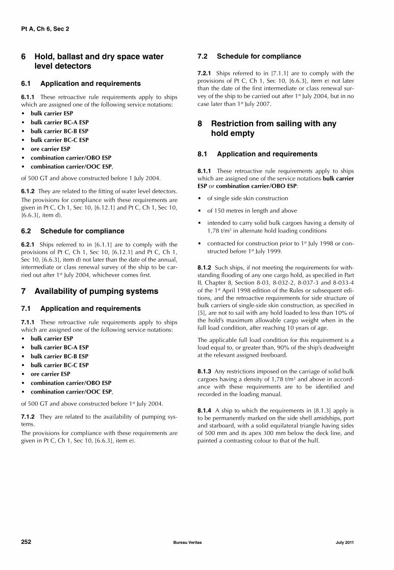
Pt A, Ch 6, Sec 2
6 Hold, ballast and dry space water level detectors
6.1 Application and requirements
6.1.1 These retroactive rule requirements apply to shipswhich are assigned one of the following service notations:• bulk carrier ESP• bulk carrier BC-A ESP• bulk carrier BC-B ESP• bulk carrier BC-C ESP• ore carrier ESP• combination carrier/OBO ESP• combination carrier/OOC ESP,
of 500 GT and above constructed before 1 July 2004.
6.1.2 They are related to the fitting of water level detectors.The provisions for compliance with these requirements aregiven in Pt C, Ch 1, Sec 10, [6.12.1] and Pt C, Ch 1, Sec 10,[6.6.3], item d).
6.2 Schedule for compliance
6.2.1 Ships referred to in [6.1.1] are to comply with theprovisions of Pt C, Ch 1, Sec 10, [6.12.1] and Pt C, Ch 1,Sec 10, [6.6.3], item d) not later than the date of the annual,intermediate or class renewal survey of the ship to be car-ried out after 1st July 2004, whichever comes first.
7 Availability of pumping systems
7.1 Application and requirements
7.1.1 These retroactive rule requirements apply to shipswhich are assigned one of the following service notations:• bulk carrier ESP• bulk carrier BC-A ESP• bulk carrier BC-B ESP• bulk carrier BC-C ESP• ore carrier ESP• combination carrier/OBO ESP• combination carrier/OOC ESP,
of 500 GT and above constructed before 1st July 2004.
7.1.2 They are related to the availability of pumping sys-tems.The provisions for compliance with these requirements aregiven in Pt C, Ch 1, Sec 10, [6.6.3], item e).
7.2 Schedule for compliance
7.2.1 Ships referred to in [7.1.1] are to comply with theprovisions of Pt C, Ch 1, Sec 10, [6.6.3], item e) not laterthan the date of the first intermediate or class renewal sur-vey of the ship to be carried out after 1st July 2004, but in nocase later than 1st July 2007.
8 Restriction from sailing with any hold empty
8.1 Application and requirements
8.1.1 These retroactive rule requirements apply to shipswhich are assigned one of the service notations bulk carrierESP or combination carrier/OBO ESP:
• of single side skin construction
• of 150 metres in length and above
• intended to carry solid bulk cargoes having a density of1,78 t/m3 in alternate hold loading conditions
• contracted for construction prior to 1st July 1998 or con-structed before 1st July 1999.
8.1.2 Such ships, if not meeting the requirements for with-standing flooding of any one cargo hold, as specified in PartII, Chapter 8, Section 8-03, 8-032-2, 8-037-3 and 8-033-4of the 1st April 1998 edition of the Rules or subsequent edi-tions, and the retroactive requirements for side structure ofbulk carriers of single-side skin construction, as specified in[5], are not to sail with any hold loaded to less than 10% ofthe hold’s maximum allowable cargo weight when in thefull load condition, after reaching 10 years of age.
The applicable full load condition for this requirement is aload equal to, or greater than, 90% of the ship’s deadweightat the relevant assigned freeboard.
8.1.3 Any restrictions imposed on the carriage of solid bulkcargoes having a density of 1,78 t/m3 and above in accord-ance with these requirements are to be identified andrecorded in the loading manual.
8.1.4 A ship to which the requirements in [8.1.3] apply isto be permanently marked on the side shell amidships, portand starboard, with a solid equilateral triangle having sidesof 500 mm and its apex 300 mm below the deck line, andpainted a contrasting colour to that of the hull.
252 Bureau Veritas July 2011

Pt A, Ch 6, Sec 3
July 2011 Bureau Veritas 253
SECTION 3 RO-RO PASSENGER SHIPS
1 General
1.1 Application
1.1.1 Ships which have been assigned the service notationro-ro passenger ship constructed before 1st July 1997 are tocomply with all the requirements indicated in [2].
2 Increased stability and watertight integrity
2.1
2.1.1 Ships referred to in [1.1.1] are to comply with theprovisions of Pt D, Ch 12, Sec 3, [1.3] not later than the firstclass renewal survey after the prescribed date of compli-ance given in Tab 1, according to the value of A/Amax asdefined in the annex of the Calculation Procedure to assessthe survivability characteristics of existing ro-ro passengerships when using a simplified method based upon resolu-tion A.265(VIII), developed by the Maritime Safety Commit-tee at its fifty-ninth session in June 1991 (MSC/Circ. 574).
Table 1 : Date of compliance according to A/Amax
2.1.2 Notwithstanding the provisions of [2.1.1], shipsreferred to in [1.1.1] which are certified to carry 400 per-sons or more are to comply with the provisions of Pt D, Ch12, Sec 3, [1.3.12], assuming the damage applied anywherewithin the ship’s length L, not later than the date of the firstclass renewal survey after the prescribed date of compli-ance, which is the one occurring the latest among thosegiven in Tab 2, Tab 3 and item a).
Table 2 : Date of compliance according to A/Amax
Table 3 : Date of compliance according tothe number of persons permitted to be carried
a) when the age of the ship is equal to or greater than 20years, where the age of the ship means the time countedfrom the date on which the keel was laid, or the date onwhich it was at a similar stage of construction, or fromthe date on which the ship was converted to a ro-ro pas-senger ship.
Value of A/Amax Date of compliance
A/Amax < 85% 1st October 1998
85% ≤ A/Amax < 90% 1st October 2000
90% ≤ A/Amax < 95% 1st October 2002
95% ≤ A/Amax < 97,5% 1st October 2004
A/Amax ≥ 97,5% 1st October 2005
Value of A/Amax Date of compliance
A/Amax < 85% 1st October 1998
85% ≤ A/Amax < 90% 1st October 2000
90% ≤ A/Amax < 95% 1st October 2002
95% ≤ A/Amax < 97,5% 1st October 2004
A/Amax ≥ 97,5% 1st October 2010
Number of persons (N.) Date of compliance
N. ≥ 1500 1st October 2002
1000 ≤ N. < 1500 1st October 2006
600 ≤ N. < 1000 1st October 2008
400 ≤ N. < 600 1st October 2010

Pt A, Ch 6, Sec 4
SECTION 4 CARGO SHIPS
1 Strength requirements for fore deck fittings and equipment, strength and securing of small hatches on the exposed fore deck
1.1 Application and requirements
1.1.1 These retroactive rule requirements apply to shipswhich are assigned one of the following service notations:
• general cargo ship
• bulk carrier (without ESP additional service feature)
• refrigerated cargo ship
• livestock carrier
• deck ship,
of 100 m in length and above, that are contracted for con-struction prior to 1st January 2004.
Note 1: The requirements also apply to dedicated forest product car-riers (other than woodchip carriers) and to dedicated cement carriers.
1.1.2 These retroactive rule requirements provide strengthrequirements to resist green sea forces for the followingitems located within the forward quarter length: air pipes,ventilator pipes and their closing devices.
They are applicable only for air pipes, ventilator pipes andtheir closing devices on the exposed deck serving spacesforward of the collision bulkhead, and to spaces whichextend over this line aft-wards.
The provisions for compliance with these strength require-ments for fore deck fittings and equipment are given in Pt C,Ch 1, Sec 10, [9.1.9].
These retroactive rule requirements are also applicable forsmall hatches on the exposed deck giving access to spacesforward of the collision bulkhead, and to spaces whichextend over this line aft-wards.
They are related to the strength of, and securing for, suchsmall hatches fitted on the exposed fore deck.
The provisions for compliance with these requirements forstrength and securing of small hatches on the exposed foredeck are given in Pt B, Ch 9, Sec 7, [9].
Note 1:
• Small hatches in the context of these retroactive rule require-ments are hatches designed for access to spaces below thedeck and capable to be closed weathertight or watertight, asapplicable. Their opening is normally 2,5 square meters or less.
• Hatches designed for emergency escape need not comply withthe requirements of Pt B, Ch 9, Sec 7, [9.4.1], items a) and b),and of Pt B, Ch 9, Sec 7, [9.4.3] and Pt B, Ch 9, Sec 7, [9.5.1].
Note 2: For ships contracted for construction prior to 1st July 2007,the following is to be carried out:
• securing devices of hatches designed for emergency escape areto be of a quick-acting type (e.g. one action wheel handles areto be provided as central locking devices for latching/unlatch-ing of hatch cover) operable from both sides of the hatch cover,
by the compliance date specified in [1.2.1] or by the due date of thefirst class renewal survey after 1st July 2007 whichever is later. Com-pletion prior to 1st July 2007 of a class renewal survey with a duedate after 1st July 2007 cannot be used to postpone compliance.
Note 3: These requirements do not apply to the cargo tank ventingsystems and the inert gas systems of tankers.
1.2 Schedule for compliance
1.2.1 Ships referred to in [1.1.1] are to comply with theprovisions of Pt B, Ch 9, Sec 7, [9] and of Pt C, Ch 1, Sec10, [9.1.9] by the following dates:• for ships which will be 15 years of age or more on
1st January 2004, by the due date of the first intermedi-ate or class renewal survey after that date
• for ships which will be 10 years of age or more on1st January 2004, by the due date of the first classrenewal survey after that date
• for ships which will be less than 10 years of age on1st January 2004, by the date on which the ship reaches10 years of age.
1.2.2 Completion, prior to 1st January 2004, of an interme-diate or class renewal survey with a due date after 1st Janu-ary 2004 cannot be used to postpone compliance.However, completion prior to 1st January 2004 of an inter-mediate survey the window for which straddles 1st January2004 can be accepted.
2 Water level detectors on single hold cargo ships other than bulk carriers
2.1 Application and requirements
2.1.1 These retroactive rule requirements normally apply toships which are assigned one of the following service nota-tions:• general cargo ship (see [2.1.1], Note 1 hereafter)• bulk carrier (without ESP additional service feature)• refrigerated cargo ship• container ship,• ro-ro cargo ship (see [2.1.1], Note 2 hereafter)• livestock carrier• deck ship (see [2.1.1], Note 2 hereafter)• liquefied gas carrier (of LPG type) (see [2.1.1], Note 2
hereafter)• supply vessel (see [2.1.1], Note 2 hereafter)
254 Bureau Veritas July 2011

Pt A, Ch 6, Sec 4
and
• of gross tonnage equal or above 500 ums, and
• constructed before 1st January 2007 with length of lessthan 80 m, or 100 m if constructed before 1st July 1998,and
• with a single cargo hold below the freeboard deck orcargo holds below the freeboard deck which are notseparated by at least one bulkhead made watertight upto that deck.
Note 1: The requirements also apply to dedicated cement carriers,dedicated forest product carriers, dedicated woodchip carriers, tim-ber and log carriers with the same conditions.
Note 2: The scope of application for these type of ships is subjectto special consideration.
2.1.2 They are related to the fitting of water level detectorsin such space or spaces.
2.1.3 The water level detectors required by the present Arti-cle need not be fitted in ships complying with Ch 6, Sec 2,[6], or in ships having watertight side compartments eachside of the cargo hold length extending vertically at leastfrom inner bottom to freeboard deck.
2.2 Schedule for compliance
2.2.1 Ships referred to in [2.1.1] are to comply with theprovisions of Ch 6, App 1, [8] not later than 31st December2009.
July 2011 Bureau Veritas 255

Pt A, Ch 6, Sec 5
256 Bureau Veritas July 2011
SECTION 5 SHIPS WITH ICE CLASSES
1 General
1.1 Application
1.1.1 Ships which have been assigned the additional classnotations ICE CLASS IB or ICE CLASS IC, the keel of whichhas been laid or which has been at a similar stage of con-struction on 1st November 1986 or thereafter, but before1st September 2003, are to comply with the requirementsindicated in [2.1.1].
1.1.2 Ships which have been assigned the additional classnotations ICE CLASS IA SUPER or ICE CLASS IA, the keel ofwhich has been laid or which has been at a similar stage ofconstruction before 1st September 2003, are to comply withthe requirements indicated in [2.1.2].
1.1.3 Ships which have been assigned one of the additionalclass notations ICE CLASS IA SUPER or ICE CLASS IA orICE CLASS IB or ICE CLASS IC built before 1st July 2007 areto comply with the requirements indicated in [3].
2 Requirements to maintain ice classes
2.1
2.1.1 Ships referred to in [1.1.1] are to comply with theprovisions of Pt F, Ch 8, Sec 1, [3.1] of the June 2000 edi-tion of the Rules, in order to maintain their additional classnotations ICE CLASS IB or ICE CLASS IC.
Note 1: In the formula of the BV Rules June 2000 edition, Pt F, Ch8, Sec 1, [3.1], the displacement restriction is applied only to thepart in the formula which is in parenthesis, and not to form factorF3. The full displacement of the ship is to be used in factor F3.
2.1.2 Ships referred to in [1.1.2] are to comply with theprovisions of Pt E, Ch 8, Sec 1, [3.1.3], in order to maintaintheir additional class notations ICE CLASS IA SUPER or ICECLASS IA, at the following dates:
• 1st January 2005 or
• 1st January in the year when 20 years has elapsed sincethe year the ship was delivered,
whichever occurs the latest.
When, for an existing ship, values for some of the hull formparameters required for the calculation method in Pt E, Ch8, Sec 1, [3.1.3] are difficult to obtain, the following alter-native formulae can be used:
• for ICE CLASS IA
C1 and C2 are to be taken as zero.
• for ICE CLASS IA SUPER
Ship without a bulb, C1 and C2 are to be calculated asfollows:
• for ICE CLASS IA SUPER
Ship with a bulb, C1 and C2 are to be calculated as fol-lows:
Values of fi and gi are given in Tab 1.
Table 1 : Values of fi and gi
C3 = 460 kg/(m2⋅s2)
C4 = 18,7 kg/(m2⋅s2)
C5 = 825 kg/s2
3 Ice class draught marking
3.1
3.1.1 Ships referred to in [1.1.3] are to be provided with awarning triangle and with an ice class draught mark at themaximum permissible ice class draught amidships as indi-cated in Pt E, Ch 8, Sec 1, Fig 2, if the UIWL is below thesummer load line, not later than the first scheduled bottomsurvey in dry-dock after the 1st July 2007.
Note 1: The upper ice waterline (UIWL) shall be the envelope ofthe highest points of the waterlines at which the ship is intended tooperate in ice. The line may be a broken line.
RCH C1 C2 C3 HF HM+( )2 B 0 658, HF+( ) C4LHF2 C5
LTB2------
⎝ ⎠⎛ ⎞
3 B4---+ + + +=
with 5 LTB2------
⎝ ⎠⎛ ⎞
3
20≤ ≤
f1 = 10,3 N/m2 g1 = 1530 N
f2 = 45,8 N/m g2 = 170 N/m
f3 = 2,94 N/m g3 = 400 N/m1,5
f4 = 5,8 N/m2
C1 f1BL
2TB--- 1+
----------------- 1 84, f2 B f3L f4BL+ +( )+=
C2 3 52, g1 g2B+( ) g3 1 1 2, TB---+
⎝ ⎠⎛ ⎞ B2
L-------+=
C1 f1BL
2TB--- 1+
----------------- 2 89, f2 B f3L f4BL+ +( )+=
C2 6 67, g1 g2B+( ) g3 1 1 2, TB---+⎝ ⎠
⎛ ⎞ B2
L-------+=

Pt A, Ch 6, App 1
APPENDIX 1 TECHNICAL RETROACTIVE REQUIREMENTS FOR BULK CARRIERS AND OTHER TYPES OF SHIPS
1 General
1.1
1.1.1 The present Appendix contains the technical require-ments applicable retroactively to existing ships listed in Ch6, Sec 2.
2 Evaluation of scantlings of the transverse watertight vertically corrugated bulkheads between the two foremost cargo holds
2.1 Application and definitions
2.1.1 These requirements apply to ships indicated in Ch 6,Sec 2, [1.1.1].
2.1.2 In these requirements, homogeneous loading condi-tion means a loading condition in which the ratio betweenthe highest and the lowest filling ratio, evaluated for the twoforemost cargo holds, does not exceed 1,20, to be correctedfor different cargo densities.
2.1.3 The net scantlings of the transverse bulkheadbetween the two foremost cargo holds are to be calculatedusing the loads given in [2.2], the bending moment andshear force given in [2.3] and the strength criteria given in[2.4].
Where necessary, steel renewal and/or reinforcements arerequired as per [2.6].
2.2 Load model
2.2.1 GeneralThe loads to be considered as acting on the bulkhead arethose given by the combination of the cargo loads withthose induced by the flooding of the foremost cargo hold.
The most severe combinations of cargo induced loads andflooding loads are to be used for the check of the scantlingsof the bulkhead, depending on the loading conditionsincluded in the loading manual:• homogeneous loading conditions• non-homogeneous loading conditions.
Non-homogeneous part loading conditions associated withmultiport loading and unloading operations for homogene-ous loading conditions need not be considered according tothese requirements.
2.2.2 Bulkhead corrugation flooding headThe flooding head hf (see Fig 1) is the distance, in m, meas-ured vertically with the ship in the upright position, fromthe calculation point to a level located at a distance df , inm, from the base line equal to:- D in general- 0,95 D for ships less than 50000 t deadweight with type
B freeboard,
D being the distance, in m, from the base line to the free-board deck at side amidships (see Fig 1).
For ships to be operated at an assigned load line draught Trless than the permissible load line draught T, the floodinghead defined for the two cases above may be reduced by(T − Tr).
Figure 1 : Calculation of pressure on the bulkhead in the flooded cargo hold
V = Volume of cargo
P = Calculation point
D
P
h1
hf
dfV
df
July 2011 Bureau Veritas 257

Pt A, Ch 6, App 1
2.2.3 Pressure in the flooded hold: bulk cargo loaded hold
Two cases are to be considered, depending on the values ofd1 and df , d1 (see Fig 1) being a distance from the base linegiven, in m, by:
where:
Mc : Mass of cargo, in t, in the foremost cargo hold
ρc : Bulk cargo density, in t/m3
lc : Length of the foremost cargo hold, in m
B : Ship’s breadth amidships, in m
vLS : Volume, in m3, of the bottom stool above theinner bottom
hHT : Height of the hopper tanks amidships, in m,from the base line
hDB : Height of the double bottom, in m
bHT : Breadth of the hopper tanks amidships, in m.
a) Case when df ≥ d1
At each point of the bulkhead located at a distancebetween d1 and df from the base line, the pressure pc,f ,in kN/m2, is given by:
pc,f = ρ g hf
where:
ρ : Sea water density, in t/m3
g : Gravity acceleration, equal to 9,81 m/s2
hf : Flooding head as defined in [2.2.2].
At each point of the bulkhead located at a distancelower than d1 from the base line, the pressure pc,f , inkN/m2, is given by:
pc,f = ρ g hf + [ρc − ρ (1 − perm)] g h1 tan2γ
where:
ρ, g, hf : As given above
ρc : Bulk cargo density, in t/m3
perm : Permeability of cargo, to be taken as 0,3 forore (corresponding bulk cargo density foriron ore may generally be taken as 3,0 t/m3)
h1 : Vertical distance, in m, from the calculationpoint to a level located at a distance d1 , asdefined above, from the base line (see Fig 1)
γ : γ = 45° − (φ / 2)
φ : Angle of repose of the cargo, in degrees,and may generally be taken as 35° for ironore.
The force Fc,f , in kN, acting on a corrugation is given by:
where:
s1 : Spacing of corrugations, in m (see Fig 2)
ρ, g, d1 , hDB : As given above
df : As given in [2.2.2]
(pc,f)le : Pressure, in kN/m2, at the lower end of thecorrugation
hLS : Height of the lower stool, in m, from theinner bottom.
b) Case when df < d1
At each point of the bulkhead located at a distancebetween df and d1 from the base line, the pressure pc,f ,in kN/m2, is given by:
pc,f = ρc g h1 tan2γ
where:
ρc, g, h1, γ : As given in a) above
At each point of the bulkhead located at a distancelower than df from the base line, the pressure pc,f , inkN/m2, is given by:
pc,f = ρ g hf + [ρc h1 − ρ (1 − perm) hf] g tan2γ
where:
ρ, g, hf , ρc , h1 , perm, γ : As given in item a) above.
The force Fc,f , in kN, acting on a corrugation is given by:
where:
s1 , ρc , g, γ, (pc,f)le , hLS : As given in a) above
d1 , hDB : As given in [2.2.3]
df : As given in [2.2.2].
2.2.4 Pressure in the flooded hold: empty hold
At each point of the bulkhead, the hydrostatic pressure pf
induced by the flooding head hf is to be considered.
The force Ff , in kN, acting on a corrugation is given by:
where:
s1 , ρ, g, hLS : As given in [2.2.3], item a)
hDB : As given in [2.2.3]
df : As given in [2.2.2].
d1Mc
ρc lcB-------------
vLS
lcB------- hHT hDB–( )bHT
B-------- hDB+ + +=
Fc f, =s1 ρgdf-d1( )2
2--------------------
ρg df-d1( ) pc f,( ) le+2
----------------------------------------------- d1 -hDB-hLS( )+
Fc f, s1 ρcgd1 df–( )2
2----------------------- γtan2=
+s1ρcg d1 df–( ) γtan2 pc f,( )le+
2------------------------------------------------------------------ df hDB– hLS–( )
Ff s1ρgdf hDB– hLS–( )2
2---------------------------------------=
258 Bureau Veritas July 2011
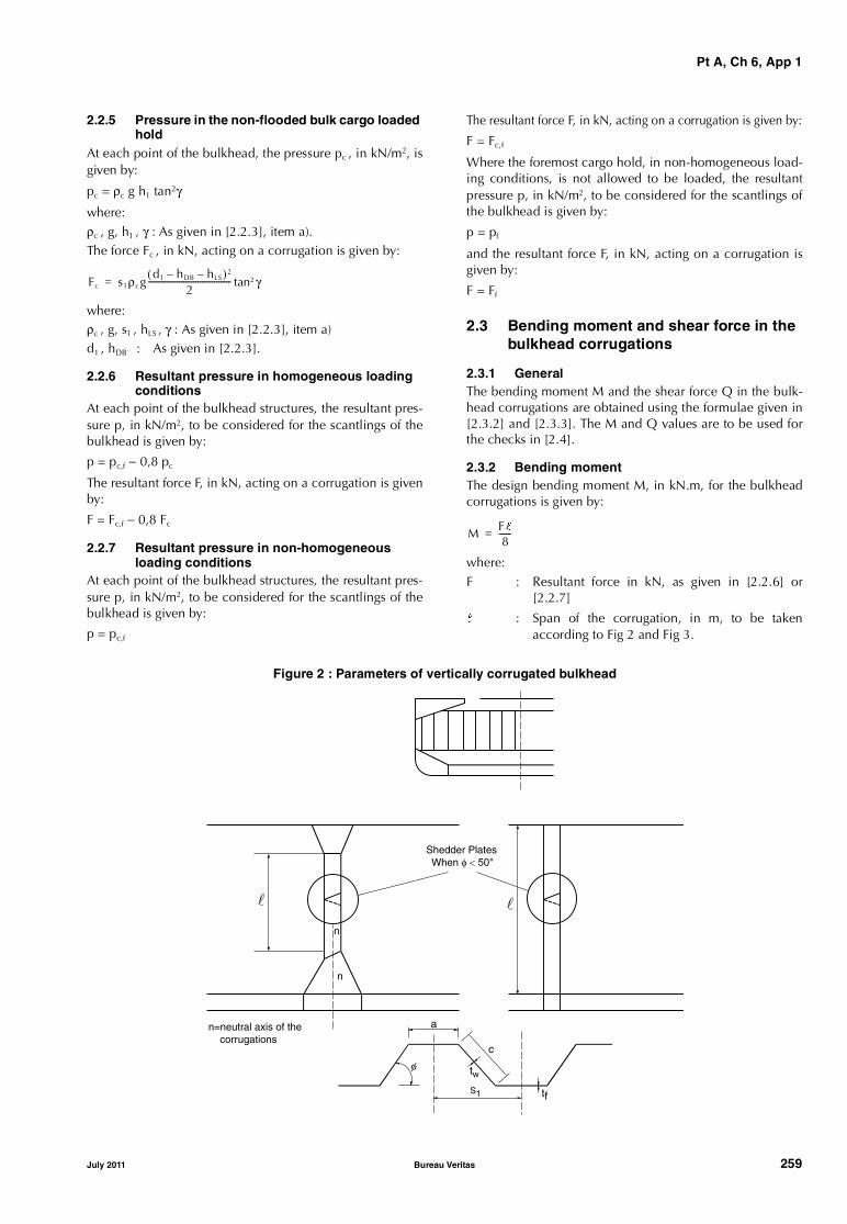
Pt A, Ch 6, App 1
2.2.5 Pressure in the non-flooded bulk cargo loaded hold
At each point of the bulkhead, the pressure pc , in kN/m2, isgiven by:
pc = ρc g h1 tan2γ
where:ρc , g, h1 , γ : As given in [2.2.3], item a).The force Fc , in kN, acting on a corrugation is given by:
where:ρc , g, s1 , hLS , γ : As given in [2.2.3], item a)d1 , hDB : As given in [2.2.3].
2.2.6 Resultant pressure in homogeneous loading conditions
At each point of the bulkhead structures, the resultant pres-sure p, in kN/m2, to be considered for the scantlings of thebulkhead is given by:
p = pc,f − 0,8 pc
The resultant force F, in kN, acting on a corrugation is givenby:
F = Fc,f − 0,8 Fc
2.2.7 Resultant pressure in non-homogeneous loading conditions
At each point of the bulkhead structures, the resultant pres-sure p, in kN/m2, to be considered for the scantlings of thebulkhead is given by:
p = pc,f
The resultant force F, in kN, acting on a corrugation is given by:
F = Fc,f
Where the foremost cargo hold, in non-homogeneous load-ing conditions, is not allowed to be loaded, the resultantpressure p, in kN/m2, to be considered for the scantlings ofthe bulkhead is given by:
p = pf
and the resultant force F, in kN, acting on a corrugation isgiven by:
F = Ff
2.3 Bending moment and shear force in the bulkhead corrugations
2.3.1 GeneralThe bending moment M and the shear force Q in the bulk-head corrugations are obtained using the formulae given in[2.3.2] and [2.3.3]. The M and Q values are to be used forthe checks in [2.4].
2.3.2 Bending momentThe design bending moment M, in kN.m, for the bulkheadcorrugations is given by:
where:F : Resultant force in kN, as given in [2.2.6] or
[2.2.7]
l : Span of the corrugation, in m, to be takenaccording to Fig 2 and Fig 3.
Figure 2 : Parameters of vertically corrugated bulkhead
Fc s1ρcgd1 hDB– hLS–( )2
2---------------------------------------- γtan2=
MFl8
------=
�
n=neutral axis of the corrugations
n
n
Shedder Plates When � � ���
a
c
tw
S1 tf
�
�
July 2011 Bureau Veritas 259

Pt A, Ch 6, App 1
Figure 3 : Definition of the corrugation span
(∗): For the definition of l, the internal end of the upper stool is not to be taken more than a distance from the deck at the centreline equal to:
- three times the depth of corrugations, in general
- twice the depth of corrugations, for rectangular stool.
2.3.3 Shear force
The shear force Q, in kN, at the lower end of the bulkheadcorrugations is given by:
Q = 0,8 F
where:
F : As given in [2.2.6] or [2.2.7].
2.4 Strength criteria
2.4.1 General
The following criteria are applicable to transverse bulk-heads with vertical corrugations (see Fig 2).
Requirements for local net plate thickness are given in [2.4.8].
In addition, the criteria given in [2.4.2] and [2.4.5] are to becomplied with.
Where the corrugation angle φ shown in Fig 2 is less than50°, a horizontal row of staggered shedder plates is to be fit-ted at approximately mid-depth of the corrugations (see Fig2) to help preserve dimensional stability of the bulkheadunder flooding loads. The shedder plates are to be weldedto the corrugations by double continuous welding, but theyare not to be welded to the side shell.
The thicknesses of the lower part of corrugations consideredin the application of [2.4.2] and [2.4.3] are to be main-tained for a distance from the inner bottom (if no lowerstool is fitted) or the top of the lower stool not less than0,15 l.
The thicknesses of the middle part of corrugations consid-ered in the application of [2.4.2] and [2.4.4] are to be main-tained to a distance from the deck (if no upper stool is fitted)or the bottom of the upper stool not greater than 0,3 l.
2.4.2 Bending capacity and shear stress τThe bending capacity is to comply with the following rela-tionship:
where:
M : Bending moment, in kN.m, as given in [2.3.2]
Zle : Section modulus of one half pitch corrugation,in cm3, at the lower end of corrugations, to becalculated according to [2.4.3]
Zm : Section modulus of one half pitch corrugation,in cm3, at the mid-span of corrugations, to becalculated according to [2.4.4]
σa,le : Allowable stress, in N/mm2, as given in [2.4.5],for the lower end of corrugations
σa,m : Allowable stress, in N/mm2, as given in [2.4.5],for the mid-span of corrugations.
In no case is Zm to be taken greater than the lesser of 1,15Zle
and 1,15Z’le for calculation of the bending capacity, Z’lebeing defined below.
Where effective shedders plates are fitted which:
- are not knuckled
- are welded to the corrugations and the top of the lowerstool by one side penetration welds or equivalent
- are fitted with a minimum slope of 45° and their loweredge is in line with the stool side plating,
or effective gusset plates are fitted which:
- are fitted in line with the stool side plating
- have material properties at least equal to those providedfor the flanges,
���� �
(*)
103 M0 5Zleσa le,, Zmσa m,+--------------------------------------------------- 1 0,≤
260 Bureau Veritas July 2011
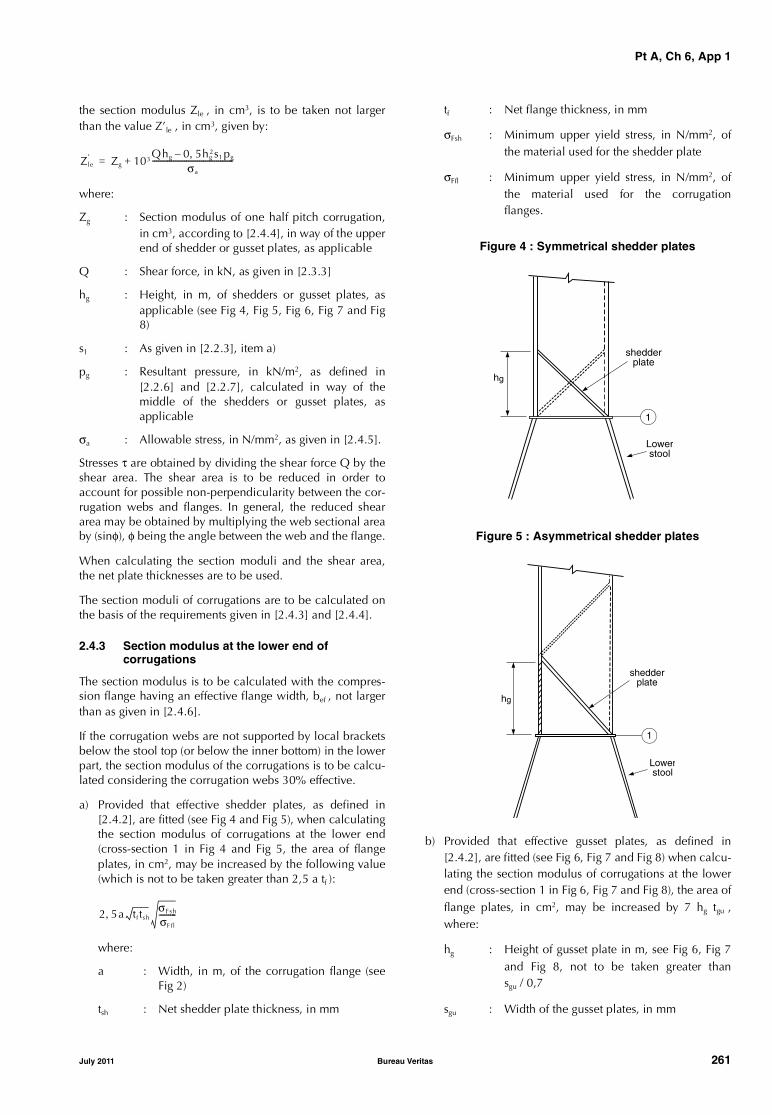
Pt A, Ch 6, App 1
the section modulus Zle , in cm3, is to be taken not largerthan the value Z’le , in cm3, given by:
where:
Zg : Section modulus of one half pitch corrugation,in cm3, according to [2.4.4], in way of the upperend of shedder or gusset plates, as applicable
Q : Shear force, in kN, as given in [2.3.3]
hg : Height, in m, of shedders or gusset plates, asapplicable (see Fig 4, Fig 5, Fig 6, Fig 7 and Fig8)
s1 : As given in [2.2.3], item a)
pg : Resultant pressure, in kN/m2, as defined in[2.2.6] and [2.2.7], calculated in way of themiddle of the shedders or gusset plates, asapplicable
σa : Allowable stress, in N/mm2, as given in [2.4.5].
Stresses τ are obtained by dividing the shear force Q by theshear area. The shear area is to be reduced in order toaccount for possible non-perpendicularity between the cor-rugation webs and flanges. In general, the reduced sheararea may be obtained by multiplying the web sectional areaby (sinφ), φ being the angle between the web and the flange.
When calculating the section moduli and the shear area,the net plate thicknesses are to be used.
The section moduli of corrugations are to be calculated onthe basis of the requirements given in [2.4.3] and [2.4.4].
2.4.3 Section modulus at the lower end of corrugations
The section modulus is to be calculated with the compres-sion flange having an effective flange width, bef , not largerthan as given in [2.4.6].
If the corrugation webs are not supported by local bracketsbelow the stool top (or below the inner bottom) in the lowerpart, the section modulus of the corrugations is to be calcu-lated considering the corrugation webs 30% effective.
a) Provided that effective shedder plates, as defined in[2.4.2], are fitted (see Fig 4 and Fig 5), when calculatingthe section modulus of corrugations at the lower end(cross-section 1 in Fig 4 and Fig 5, the area of flangeplates, in cm2, may be increased by the following value(which is not to be taken greater than 2,5 a tf ):
where:
a : Width, in m, of the corrugation flange (seeFig 2)
tsh : Net shedder plate thickness, in mm
tf : Net flange thickness, in mm
σFsh : Minimum upper yield stress, in N/mm2, ofthe material used for the shedder plate
σFfl : Minimum upper yield stress, in N/mm2, ofthe material used for the corrugationflanges.
Figure 4 : Symmetrical shedder plates
Figure 5 : Asymmetrical shedder plates
b) Provided that effective gusset plates, as defined in[2.4.2], are fitted (see Fig 6, Fig 7 and Fig 8) when calcu-lating the section modulus of corrugations at the lowerend (cross-section 1 in Fig 6, Fig 7 and Fig 8), the area offlange plates, in cm2, may be increased by 7 hg tgu ,where:
hg : Height of gusset plate in m, see Fig 6, Fig 7and Fig 8, not to be taken greater thansgu / 0,7
sgu : Width of the gusset plates, in mm
Zle′ Zg 103
Qhg 0 5hg2s1 pg,–
σa
-------------------------------------------+=
2 5a tf tshσFsh
σFfl
---------,
1
Lowerstool
shedderplate
hg
1
hg
Lowerstool
shedderplate
July 2011 Bureau Veritas 261

Pt A, Ch 6, App 1
tgu : Net gusset plate thickness, in mm, not to betaken greater than tf
tf : Net flange thickness, in mm, based on theas-built condition.
c) If the corrugation webs are welded to a sloping stool topplate, which is at an angle not less than 45° with thehorizontal plane, the section modulus of the corruga-tions may be calculated considering the corrugationwebs fully effective. Where effective gusset plates arefitted, when calculating the section modulus of corruga-tions the area of flange plates may be increased as spec-ified in b) above. No credit can be given to shedderplates only.
For angles less than 45°, the effectiveness of the webmay be obtained by linear interpolation between 30%for 0° and 100% for 45°.
Figure 6 : Symmetrical gusset/shedder plates
Figure 7 : Asymmetrical gusset/shedder plates
Figure 8 : Asymmetrical gusset/shedder platesSloping stool top plate
2.4.4 Section modulus of corrugations at cross-sections other than the lower end
The section modulus is to be calculated with the corruga-tion webs considered effective and the compression flangehaving an effective flange width not larger than as given in[2.4.6].
2.4.5 Allowable stress check
The normal and shear stresses σ and τ are not to exceed theallowable values σa and τa , in N/mm2, given by:
σa = σF
τa = 0,5 σF
where:
σF : Minimum upper yield stress, in N/mm2, of thematerial.
2.4.6 Effective width of the compression flange of corrugations
The effective width bef , in m, of the corrugation flange isgiven by:
bef = Ce a
where:
tf : Net flange thickness, in mm
a : As given in [2.4.2]
σF : Minimum upper yield stress, in N/mm2, of thematerial
E : Modulus of elasticity, in N/mm2, to be assumedequal to 206000 N/mm2 for steel.
1
hg
Lowerstool
gussetplate
hg
1
Lowerstool
gussetplate
gh
=
=
gussetplate
lowerstool
1
Ce2 25,
β------------- 1 25,
β2-------------–= for β 1 25,>
Ce 1= for β 1 25,≤
β 103 atf
--- σF
E-----=
262 Bureau Veritas July 2011

Pt A, Ch 6, App 1
2.4.7 Shear buckling check
The buckling check is to be performed for the web plates atthe corrugation ends.
The shear stress τ is not to exceed the critical value τC , inN/mm2, obtained as follows:
where:
σF : Minimum upper yield stress, in N/mm2, of thematerial
kt = 6,34
E : Modulus of elasticity, in N/mm2, as given in[2.4.6]
t : Net thickness, in mm, of corrugation web
c : Width, in m, of corrugation web (see Fig 2).
2.4.8 Local net plate thickness
The bulkhead local net plate thickness t, in mm, is given by:
where:
sw : Plate width, in m, to be taken equal to the widthof the corrugation flange or web, whichever isthe greater (see Fig 2)
p : Resultant pressure, in kN/m2, as defined in[2.2.6] and [2.2.7], at the bottom of each strakeof plating; in all cases, the net thickness of thelowest strake is to be determined using theresultant pressure at the top of the lower stool orat the inner bottom, if no lower stool is fitted, orat the top of shedders, if shedder or gusset/shed-der plates are fitted
σF : Minimum upper yield stress, in N/mm2, of thematerial.
For built-up corrugation bulkheads, when the thicknesses ofthe flange and web are different, the net thickness of thenarrower plating is to be not less than tn , in mm, given by:
where:
sn : Width, in m, of the narrower plating.
The net thickness of the wider plating, in mm, is not to betaken less than the maximum of the following values:
where:
tnp : Thickness, in mm, less or equal to the actual netthickness of the narrower plating and not to begreater than:
2.5 Local details
2.5.1 General
As applicable, the design of local details is to comply withthe Society’s requirements for the purpose of transferring thecorrugated bulkhead forces and moments to the boundarystructures, especially to the double bottom and cross-deckstructures.
In particular, the thickness and stiffness of gusset and shed-der plates, as defined in [2.4.3], installed for strengtheningpurposes, are to comply with the Society’s requirements onthe basis of the load model in [2.2].
Unless otherwise stated, weld connections and materialsare to be dimensioned and selected in accordance with theSociety’s requirements.
2.6 Steel renewal
2.6.1 General
Renewal/reinforcement is to be carried out in accordancewith the following requirements and the guidelines con-tained in [3].
2.6.2 Steel renewal is required where the gauged thicknessis less than (tnet + 0,5) mm, tnet being the thickness used forthe calculation of bending capacity and shear stresses asgiven in [2.4.2] or the local net plate thickness as given in[2.4.8]. Alternatively, reinforcing doubling strips may beused providing the net thickness is not dictated by shearstrength requirements for web plates (see [2.4.5] and[2.4.7]) or by local pressure requirements for web andflange plates (see [2.4.8]).
Where steel renewal is required, the bulkhead connectionsto the lower stool shelf plate (or inner bottom, if no stool isfitted) are to be made at least by deep penetration welds(see Fig 9).
Where the gauged thickness is within the range (tnet + 0,5)mm and (tnet + 1,0) mm, coating (applied in accordancewith the coating Manufacturer’s specifications) or annualgauging may be adopted as an alternative to steel renewal.
2.6.3 Where steel renewal or reinforcement is required, aminimum thickness of (tnet + 2,5) mm is to be replenishedfor the renewed or reinforced parts.
τC τE= for τEτF
2----≤
τC τF 1τF
4τE
--------–⎝ ⎠⎛ ⎞= for τE
τF
2---->
τFσF
3-------=
τE 0 9ktEt
1000c----------------
⎝ ⎠⎛ ⎞
2
,=
t 14 9swpσF
-----,=
tn 14 9snpσF
-----,=
tw 14 9swpσF
-----,=
tw440sw
2 pσF
------------------- tnp2–=
14 9swpσF
-----,
July 2011 Bureau Veritas 263

Pt A, Ch 6, App 1
Figure 9 : Deep penetration welds of shedder and gusset plates
Root face (f): 3 mm to T/3 mm Groove angle (α): 40° to 60°
2.6.4 Gussets with shedder plates, extending from thelower end of corrugations up to 0,1 l, or reinforcing dou-bling strips (on bulkhead corrugations and stool side plat-ing) are to be fitted when:
where:σFfl : Minimum upper yield stress, in N/mm2, of the
material used for the corrugation flangesσFs : Minimum upper yield stress, in N/mm2, of the
material used for the lower stool side plating (orfloors, if no stool is fitted)
tfl : Flange thickness, in mm, which is found to beacceptable on the basis of the criteria specifiedin [2.6.2] or, when steel renewal is required, thereplenished thickness according to the criteriaspecified in [2.6.3]. The above flange thicknessdictated by local pressure requirements (see[2.4.8]) need not be considered for this purpose
tst : As-built thickness, in mm, of the lower stoolside plating (or floors, if no stool is fitted).
If gusset plates are fitted, their material is to be the same asthat of the corrugation flanges. The gusset plates are to beconnected to the lower stool shelf plate (or inner bottom, ifno lower stool is fitted) by deep penetration welds (see Fig9).
Where gusset plates are to be fitted or renewed, their con-nections with the corrugations and the lower stool shelfplate (or inner bottom, if no stool is fitted) are to be made atleast by deep penetration welds (see Fig 9).
3 Guidance on renewal/reinforcement of the transverse watertight vertically corrugated bulkhead between the two foremost cargo holds
3.1
3.1.1 The need for renewal or reinforcement of the trans-verse watertight vertically corrugated bulkhead between thetwo foremost cargo holds will be determined by the Societyon a case-by-case basis using the criteria given in [2] in asso-ciation with the most recent gaugings and survey findings.
3.1.2 In addition to Rule requirements, the assessment ofthe transverse corrugated bulkhead based on the criteriagiven in [2] will take into account the following:
• scantlings of individual vertical corrugations will beassessed for reinforcement/renewal based on thicknessmeasurements obtained in accordance with Ch 6, Sec2, [1.3] at their lower end, at mid-depth and in way ofplate thickness changes in the lower 70%. These consid-erations will take into account the provision of gussetsand shedder plates and the benefits they offer, providedthat they comply with [2.4.2] and [2.6].
• taking into account the scantlings and arrangements foreach case, permissible levels of diminution will bedetermined and appropriate measures taken in accord-ance with [2.6].
3.1.3 Where renewal is required, its extent is to be shownclearly in plans. The vertical distance of each renewal zoneis to be determined by considering the criteria given in [2]and is generally to be not less than 15% of the vertical dis-tance between the upper and lower end of the corrugationmeasured at the ship’s centreline.
3.1.4 Where the reinforcement is accepted by addingstrips, the length of the reinforcing strips is to be sufficient toextend over the whole depth of the diminished plating. Ingeneral, the width and thickness of strips are to be sufficientto comply with the criteria given in [2]. The material of thestrips is to be the same as that of the corrugation plating.The strips are to be attached to the existing bulkhead platingby continuous fillet welds. The strips are to be suitablytapered or connected at ends in accordance with the usualwelding practice to the Surveyor’s satisfaction.
3.1.5 Where reinforcing strips are connected to the innerbottom or lower stool shelf plates, one side full penetrationwelding is to be used. When reinforcing strips are fitted tothe corrugation flange and are connected to the lower stoolshelf plate, they are normally to be aligned with strips of thesame scantlings welded to the stool side plating and havinga minimum length equal to the breadth of the corrugationflange.
�
�
� �
�
�
�
σFs tst
σFf ltf l
------------ 0 8,≤
264 Bureau Veritas July 2011

Pt A, Ch 6, App 1
Figure 10 : Reinforcement of vertically corrugated bulkhead
����������� ��� � ��� ������� ��� ����� ����
���� �� ����������� ��� � ����� �������������� ��� � ��� ������� ���
����� �������� �����
����� ���
������� ���
��������������
����� �������� �����
����� ��������� ���
����������������
��������������
��� ���� ���� ������������
��������������
����� ����� ���
����� ���
����� ��� � �� � ��������� ����� ��� ��������� �� �����
� �� ��� � ��������� � ����
������ �������������� � � �� ������� ������ � �� ��� �������������� ����� ���
����� ��� � �� ������� ����� ����� �� ���� �������� ����
� �� ��� � ��������� � ����
July 2011 Bureau Veritas 265

Pt A, Ch 6, App 1
3.1.6 Fig 10 gives a general arrangement of structural rein-forcement. When such reinforcement is carried out, the fol-lowing applies:
• square or trapezoidal corrugations are to be reinforcedwith plate strips fitted to each corrugation flange suffi-cient to meet the requirements given in [2]
• the number of strips fitted to each corrugation flange isto be sufficient to meet the requirements given in [2]
• the shedder plate may be fitted in one piece or prefabri-cated with a welded knuckle (gusset plate)
• gusset plates, where fitted, are to be welded to the shelfplate in line with the flange of the corrugation, toreduce the stress concentrations at the corrugation cor-ners. Good alignment is to be ensured between gussetplates, corrugation flanges and lower stool slopingplates. Deep penetration welding is to be used at allconnections. Start and stop of welding are to be as faraway as possible from corners of corrugations
• shedder plates are to be attached by one side full pene-tration welds onto backing bars
• shedder and gusset plates are to have a thickness equalto or greater than the original bulkhead thickness. Gus-set plates are to have a minimum height (on the verticalpart) equal to half of the width of the corrugation flange.Shedders and gussets are to be of the same material asthat of the flange.
4 Evaluation of allowable hold loading of the foremost cargo hold with the same cargo hold flooded
4.1 Application and definitions
4.1.1 These requirements apply to bulk carriers:
• of single side skin construction
• of 150 metres in length and above
• intended to carry solid bulk cargoes having a bulk den-sity of 1,78 t/m3 or above
• contracted for construction prior to 1st July 1998, andnot constructed in compliance with the applicablerequirements for new buildings contracted after thatdate, and given in Pt D, Ch 4, Sec 3.
4.1.2 The loading in the foremost cargo hold is not toexceed the allowable hold loading in the flooded condition,calculated as per [4.4], using the loads given in [4.2] andthe shear capacity of the double bottom given in [4.3].
In no case is the allowable hold loading in flooding condi-tion to be taken greater than the design hold loading inintact condition.
4.2 Load model
4.2.1 GeneralThe loads to be considered as acting on the double bottom ofthe foremost cargo hold are those given by the external seapressures and the combination of the cargo loads with thoseinduced by the flooding of the foremost cargo hold itself.
The most severe combinations of cargo induced loads andflooding loads are to be used, depending on the loadingconditions included in the loading manual:
• homogeneous loading conditions
• non-homogeneous loading conditions
• packed cargo conditions, such as steel mill products.
For each loading condition, the maximum bulk cargo den-sity to be carried is to be considered in calculating theallowable hold limit.
4.2.2 Inner bottom flooding headThe flooding head hf (see Fig 11) is the distance, in m, meas-ured vertically with the ship in the upright position, fromthe inner bottom to a level located at a distance df , in m,from the base line equal to:
- D in general
- 0,95 D for ships less than 50,000 tonnes deadweightwith type B freeboard,
D being the distance, in m, from the base line to the free-board deck at side amidships (see Fig 11).
Figure 11 : Calculation of pressure on the inner bottom in the flooded cargo hold
V = Volume of cargo
Dh1
V
hf
df
266 Bureau Veritas July 2011

Pt A, Ch 6, App 1
4.3 Shear capacity of the double bottom of the foremost cargo hold
4.3.1 General
The shear capacity C of the double bottom of the foremostcargo hold is defined as the sum of the shear strength ateach end of:
• all floors adjacent to both hoppers, less one half of thestrength of the two floors adjacent to each stool, ortransverse bulkhead if no stool is fitted (see Fig 12)
• all double bottom girders adjacent to both stools, ortransverse bulkheads if no stool is fitted.
The strength of girders or floors which run out and are notdirectly attached to the boundary stool or hopper girder isto be evaluated for the one end only.
Note 1: The floors and girders to be considered are those inside thehold boundaries formed by the hoppers and stools (or transversebulkheads if no stool is fitted). The hopper side girders and thefloors directly below the connection of the bulkhead stools (ortransverse bulkheads if no stool is fitted) to the inner bottom are notto be included.
Note 2: When the geometry and/or the structural arrangement ofthe double bottom is such as to make the above assumptions inad-equate, at the Society’s discretion, the shear capacity C of the dou-ble bottom is to be calculated by means of direct calculations to becarried out according to Pt B, Ch 7, App 1, as far as applicable.
In calculating the shear strength, the net thicknesses offloors and girders are to be used. The net thickness tnet , inmm, is given by:
tnet = t − tC
where:
t : As-built thickness, in mm, of floors and girders
tC : Corrosion diminution, equal to 2 mm, in gen-eral; a lower value of tC may be adopted, pro-vided that measures are taken, to the Society’ssatisfaction, to justify the assumption made.
4.3.2 Floor shear strengthThe floor shear strength in way of the floor panel adjacent tohoppers Sf1 , in kN, and the floor shear strength in way ofthe openings in the outermost bay (i.e. that bay which isclosest to the hopper) Sf2 , in kN, are given by the followingexpressions:
where:
Af : Sectional area, in mm2, of the floor panel adja-cent to hoppers
Af,h : Net sectional area, in mm2, of the floor panelsin way of the openings in the outermost bay (i.e.that bay which is closest to the hopper)
τa : Allowable shear stress, in N/mm2, to be takenequal to:
σF : Minimum upper yield stress, in N/mm2, of thematerial
η1 : η1 = 1,10
η2 : η2 = 1,20
η2 may be reduced, at the Society’s discretion,down to 1,10 where appropriate reinforcementsare fitted to the Society’s satisfaction.
Figure 12 : Double bottom structure
Sf1 10 3– Afτa
η1
-----=
Sf2 10 3– Af h,τa
η2
-----=
τaσF
3-------=
Lower stool
Floor adjacentto the stool
Transverse bulkhead
Floor adjacent to thetransverse bulkhead
Girders
Floors
CL
July 2011 Bureau Veritas 267

Pt A, Ch 6, App 1
4.3.3 Girder shear strength
The girder shear strength in way of the girder panel adjacentto stools (or transverse bulkheads, if no stool is fitted) Sg1 , inkN, and the girder shear strength in way of the largest open-ing in the outermost bay (i.e. that bay which is closest to thestool, or transverse bulkhead, if no stool is fitted) Sg2 , in kN,are given by the following expressions:
where:
Ag : Minimum sectional area, in mm2, of the girderpanel adjacent to stools (or transverse bulk-heads if no stools are fitted)
Ag,h : Net sectional area, in mm2, of the girder panelin way of the largest opening in the outermostbay (i.e. that bay which is closest to the stool, ortransverse bulkhead, if no stool is fitted)
τa : Allowable shear stress, in N/mm2, as given in[4.3.2]
η1 : η1 = 1,10
η2 : η2 = 1,15
η2 may be reduced, at the Society’s discretion,down to 1,10 where appropriate reinforcementsare fitted to the Society’s satisfaction.
4.4 Allowable hold loading
4.4.1 The allowable hold loading W, in t, is given by:
where:
F : Equal to 1,05 in general (for steel mild products,F = 1,0)
ρc : Cargo density, in t/m3; for bulk cargoes see[4.2.1]; for steel products, ρc is to be taken asthe density of steel
V : Volume, in m3, occupied by cargo at a level h1
given by:
where:
X : For bulk cargoes, is the lesser of X1 and X2 givenby:
Note 1: For steel products, X may be taken equal to X1, usingperm = 0
ρ : Sea water density, in t/m3
g : 9,81 m/s2, gravity acceleration
E : E = df − 0,1 D
with df and D as given in [4.2.2]
hf : Flooding head, in m, as defined in [4.2.2]
perm : Permeability of cargo, to be taken as 0,3 for ore(corresponding bulk cargo density for iron oremay generally be taken as 3,0 t/m3)
Z : The lesser of Z1 and Z2 given by:
with:
Ch : Shear capacity of the double bottom, in kN, asdefined in [4.3], considering, for each floor, thelesser of the shear strengths Sf1 and Sf2 (see[4.3.2]) and, for each girder, the lesser of theshear strengths Sg1 and Sg2 (see [4.3.3])
Ce : Shear capacity of the double bottom, in kN, asdefined in [4.3], considering, for each floor, theshear strength Sf1 (see [4.3.2]) and, for eachgirder, the lesser of the shear strengths Sg1 andSg2 (see [4.3.3])
ADB,h :
ADB,e :
where:
n : Number of floors between stools (or transversebulkheads, if no stools are fitted)
Si : Space of the ith-floor, in m
BDB,i : • for floors whose shear strength is given bySf1 (see [4.3.2]): BDB,i = BDB − s
• for floors whose shear strength is given bySf2 (see [4.3.2]): BDB,i = BDB,h
where BDB,h is the distance, in m, between thetwo openings considered (see Fig 13)
BDB : Breadth of double bottom, in m, between hop-pers (see Fig 13)
s : Spacing, in m, of double bottom longitudinalsadjacent to hoppers.
Figure 13 : Dimensions BDB and BDB,h
Sg1 10 3– Agτa
η1
-----=
Sg2 10 3– Ag h,τa
η2
-----=
W ρcV1F---=
h1X
ρc g--------=
X1Z ρg E hf–( )+
1 ρρc
----- perm 1–( )+--------------------------------------------=
X2 Z ρg E hfperm–( )+=
Z1Ch
ADB h,-------------=
Z2Ce
ADB e,------------=
ADB h, SiBDB i,
i 1=
i n=
∑=
ADB e, Si BDB s–( )i 1=
i n=
∑=
BDB,h
BDB
268 Bureau Veritas July 2011
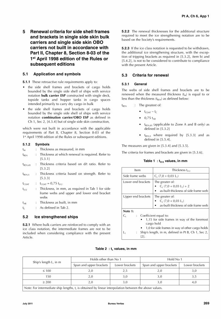
Pt A, Ch 6, App 1
5 Renewal criteria for side shell frames and brackets in single side skin bulk carriers and single side skin OBO carriers not built in accordance with Part II, Chapter 8, Section 8-03 of the 1st April 1998 edition of the Rules or subsequent editions
5.1 Application and symbols
5.1.1 These retroactive rule requirements apply to:
• the side shell frames and brackets of cargo holdsbounded by the single side shell of ships with servicenotation bulk carrier ESP constructed with single deck,topside tanks and hopper tanks in cargo spacesintended primarily to carry dry cargo in bulk
• the side shell frames and brackets of cargo holdsbounded by the single side shell of ships with servicenotation combination carrier/OBO ESP as defined inCh 1, Sec 2, [4.3.4] but of single side skin construction,
which were not built in accordance with the applicablerequirements of Part II, Chapter 8, Section 8-03 of the1st April 1998 edition of the Rules or subsequent editions.
5.1.2 Symbols tM : Thickness as measured, in mm
tREN : Thickness at which renewal is required. Refer to[5.3.1]
tREN,d/t : Thickness criteria based on d/t ratio. Refer to[5.3.2]
tREN,S : Thickness criteria based on strength. Refer to[5.3.3]
tCOAT : tCOAT = 0,75 tS12
tS12 : Thickness, in mm, as required in Tab 1 for sideframe webs and upper and lower end bracketwebs
tAB : Thickness as built, in mm
tC : As defined in Tab 2.
5.2 Ice strengthened ships
5.2.1 Where bulk carriers are reinforced to comply with anice class notation, the intermediate frames are not to beincluded when considering compliance with the presentArticle.
5.2.2 The renewal thicknesses for the additional structurerequired to meet the ice strengthening notation are to bebased on the Society’s requirements.
5.2.3 If the ice class notation is requested to be withdrawn,the additional ice strengthening structure, with the excep-tion of tripping brackets as required in [5.3.2], item b) and[5.4.2], is not to be considered to contribute to compliancewith the present Article.
5.3 Criteria for renewal
5.3.1 General
The webs of side shell frames and brackets are to berenewed when the measured thickness (tM) is equal to orless than the thickness (tREN) as defined below:
tREN : The greatest of:
• tCOAT − tC
• 0,75 tAB
• tREN,d/t (applicable to Zone A and B only) asdefined in [5.3.2]
• tREN,S where required by [5.3.3] and asdefined in [5.5.4].
The measures are given in [5.3.4] and [5.3.5].
The criteria for frames and brackets are given in [5.3.6].
Table 1 : tS12 values, in mm
Table 2 : tc values, in mm
Item Thickness tS12
Side frame webs CL (7,0 + 0,03 L1)
Lower end brackets The greater of:• CL (7,0 + 0,03 L1) + 2• as-built thickness of side frame web
Upper end brackets The greater of:• CL (7,0 + 0,03 L1)• as-built thickness of side frame web
Note 1:CL : Coefficient equal to:
• 1,15 for side frames in way of the foremostcargo hold
• 1,0 for side frames in way of other cargo holdsL1 : Ship’s length, in m, defined in Pt B, Ch 1, Sec 2,
[2].
Ship’s length L, in mHolds other than No 1 Hold No 1
Span and upper brackets Lower brackets Span and upper brackets Lower brackets
≤ 100 2,0 2,5 2,0 3,0
150 2,0 3,0 3,0 3,5
≥ 200 2,0 3,0 3,0 4,0
Note: For intermediate ship lengths, tc is obtained by linear interpolation between the above values.
July 2011 Bureau Veritas 269

Pt A, Ch 6, App 1
5.3.2 Thickness criteria based on d/t ratio
Subject to items b) and c) below tREN,d/t is given by the fol-lowing formula:
where:
d : Web depth, in mm
R : Coefficient given as follows:
• frames:
65 k0,5 for symmetrically flanged frames
55 k0,5 for asymmetrically flanged frames
• lower brackets (see item a) below):
87 k0,5 for symmetrically flanged frames
73 k0,5 for asymmetrically flanged frames
k : Coefficient given in Pt B, Ch 4, Sec 1, [2.3]
k = 1 for ordinary hull structural steel.
In no instance is tREN,d/t for lower integral brackets to betaken as less than tREN,d/t for the frames they support.
a) Lower brackets
Lower brackets are to be flanged or face plate is to befitted. Refer to [5.3.6].
In calculating the web depth of the lower brackets, thefollowing items apply:
- The web depth of lower bracket may be measuredfrom the intersection of the sloped bulkhead of thehopper tank and the side shell plate, perpendicu-larly to the face plate of the lower bracket (refer toFig 14)
- Where stiffeners are fitted on the lower bracketplate, the web depth may be taken as the distancebetween the side shell and the stiffener, between thestiffeners or between the outermost stiffener and theface plate of the brackets, whichever is the greatest.
Figure 14 : Definition of the lower bracket web depth for determining tREN,d/t
b) Tripping bracket alternative
When tM is less than tREN,d/t at section b) of the sideframes, tripping brackets in accordance with [5.4.2]may be fitted as an alternative to the requirements forthe web depth to thickness ratio of side frames, in whichcase tREN,d/t may be disregarded in the determination oftREN in accordance with [5.3.1]. The value of tM is to bebased on zone B according to Fig 15.
Figure 15 : Lower part and zones of side frames
c) Immediately abaft collision bulkhead
For the side frames, including the lower bracket, locatedimmediately abaft the collision bulkhead, whose scant-lings are increased in order that their moment of inertiais such to avoid undesirable flexibility of the side shell,when their web as built thickness tAB is greater than1,65tREN,S the thickness tREN,d/t may be taken as the valuet′REN,d/t obtained from the following formula:
where tREN,S is obtained from [5.5.4].
5.3.3 Thickness criteria based on shear strength check
Where tM in the lower part of side frames, as defined in Fig15, is equal to or less than tCOAT , tREN,S is to be determined inaccordance with [5.5.4].
5.3.4 Thickness of renewed webs of frames and lower brackets
Where steel renewal is required, the renewed webs are tobe of a thickness not less than tAB, 1,2tCOAT or 1,2tREN, which-ever is the greatest.
tREN d t⁄,dR---=
���� ���
���� �� �� �� �����
���
�����
�
�����
�
�
��� ���� �
���� �����
��
�
�
tREN d t⁄,′ t2
REN d t⁄, tREN S,⋅3=
270 Bureau Veritas July 2011
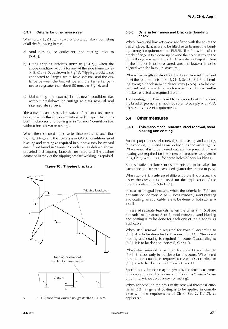
Pt A, Ch 6, App 1
5.3.5 Criteria for other measures
When tREN < tM ≤ tCOAT, measures are to be taken, consistingof all the following items:
a) sand blasting, or equivalent, and coating (refer to[5.4.1])
b) Fitting tripping brackets (refer to [5.4.2]), when theabove condition occurs for any of the side frame zonesA, B, C and D, as shown in Fig 15. Tripping brackets notconnected to flanges are to have soft toe, and the dis-tance between the bracket toe and the frame flange isnot to be greater than about 50 mm, see Fig 16, and
c) Maintaining the coating in “as-new” condition (i.e.without breakdown or rusting) at class renewal andintermediate surveys.
The above measures may be waived if the structural mem-bers show no thickness diminution with respect to the asbuilt thicknesses and coating is in “as-new” condition (i.e.without breakdown or rusting).
When the measured frame webs thickness tM is such thattREN < tM ≤ tCOAT and the coating is in GOOD condition, sandblasting and coating as required in a) above may be waivedeven if not found in “as-new” condition, as defined above,provided that tripping brackets are fitted and the coatingdamaged in way of the tripping bracket welding is repaired.
Figure 16 : Tripping brackets
x : Distance from knuckle not greater than 200 mm.
5.3.6 Criteria for frames and brackets (bending check)
When lower end brackets were not fitted with flanges at thedesign stage, flanges are to be fitted so as to meet the bend-ing strength requirements in [5.5.5]. The full width of thebracket flange is to extend up beyond the point at which theframe flange reaches full width. Adequate back-up structurein the hopper is to be ensured, and the bracket is to bealigned with the back-up structure.
Where the length or depth of the lower bracket does notmeet the requirements in Pt D, Ch 4, Sec 3, [3.2.6], a bend-ing strength check in accordance with [5.5.5] is to be car-ried out and renewals or reinforcements of frames and/orbrackets effected as required therein.
The bending check needs not to be carried out in the casethe bracket geometry is modified so as to comply with Pt D,Ch 4, Sec 3, [3.2.6] requirements.
5.4 Other measures
5.4.1 Thickness measurements, steel renewal, sand blasting and coating
For the purpose of steel renewal, sand blasting and coating,four zones A, B, C and D are defined, as shown in Fig 15.When renewal is to be carried out, surface preparation andcoating are required for the renewed structures as given inPt D, Ch 4, Sec 3, [8.1] for cargo holds of new buildings.
Representative thickness measurements are to be taken foreach zone and are to be assessed against the criteria in [5.3].
When zone B is made up of different plate thicknesses, thelesser thickness is to be used for the application of therequirements in this Article [5].
In case of integral brackets, when the criteria in [5.3] arenot satisfied for zone A or B, steel renewal, sand blastingand coating, as applicable, are to be done for both zones Aand B.
In case of separate brackets, when the criteria in [5.3] arenot satisfied for zone A or B, steel renewal, sand blastingand coating is to be done for each one of these zones, asapplicable.
When steel renewal is required for zone C according to[5.3], it is to be done for both zones B and C. When sandblasting and coating is required for zone C according to[5.3], it is to be done for zones B, C and D.
When steel renewal is required for zone D according to[5.3], it needs only to be done for this zone. When sandblasting and coating is required for zone D according to[5.3], it is to be done for both zones C and D.
Special consideration may be given by the Society to zonespreviously renewed or recoated, if found in “as-new” con-dition (i.e. without breakdown or rusting).
When adopted, on the basis of the renewal thickness crite-ria in [5.3], in general coating is to be applied in compli-ance with the requirements of Ch 4, Sec 2, [1.1.7], asapplicable.
Tripping brackets
x
~50mm
Tripping bracket notwelded to frame flange
July 2011 Bureau Veritas 271
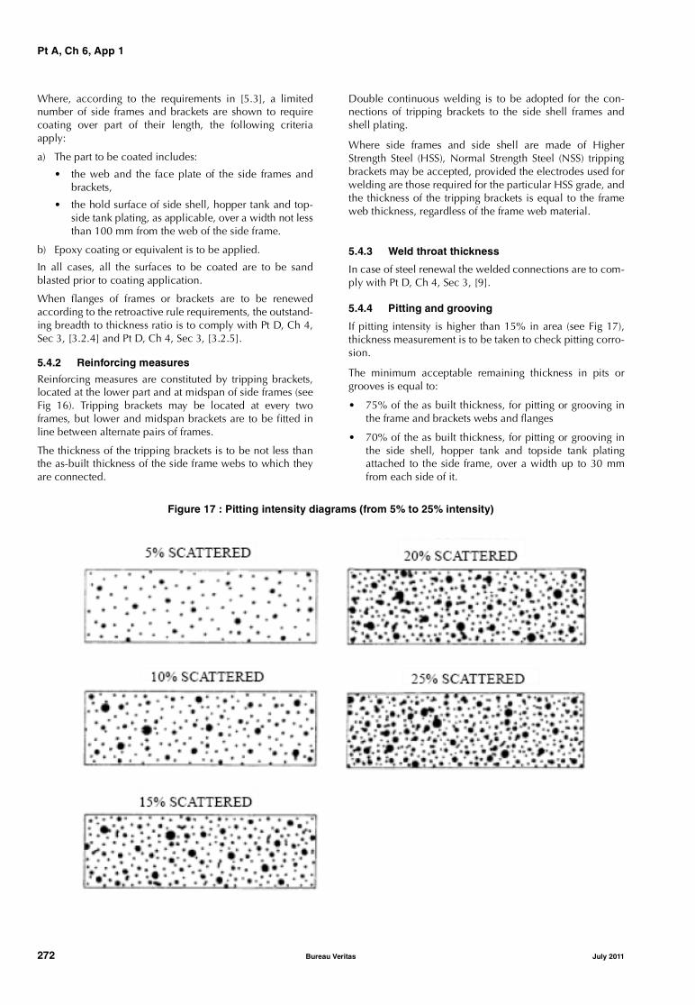
Pt A, Ch 6, App 1
Where, according to the requirements in [5.3], a limitednumber of side frames and brackets are shown to requirecoating over part of their length, the following criteriaapply:
a) The part to be coated includes:
• the web and the face plate of the side frames andbrackets,
• the hold surface of side shell, hopper tank and top-side tank plating, as applicable, over a width not lessthan 100 mm from the web of the side frame.
b) Epoxy coating or equivalent is to be applied.
In all cases, all the surfaces to be coated are to be sandblasted prior to coating application.
When flanges of frames or brackets are to be renewedaccording to the retroactive rule requirements, the outstand-ing breadth to thickness ratio is to comply with Pt D, Ch 4,Sec 3, [3.2.4] and Pt D, Ch 4, Sec 3, [3.2.5].
5.4.2 Reinforcing measures
Reinforcing measures are constituted by tripping brackets,located at the lower part and at midspan of side frames (seeFig 16). Tripping brackets may be located at every twoframes, but lower and midspan brackets are to be fitted inline between alternate pairs of frames.
The thickness of the tripping brackets is to be not less thanthe as-built thickness of the side frame webs to which theyare connected.
Double continuous welding is to be adopted for the con-nections of tripping brackets to the side shell frames andshell plating.
Where side frames and side shell are made of HigherStrength Steel (HSS), Normal Strength Steel (NSS) trippingbrackets may be accepted, provided the electrodes used forwelding are those required for the particular HSS grade, andthe thickness of the tripping brackets is equal to the frameweb thickness, regardless of the frame web material.
5.4.3 Weld throat thickness
In case of steel renewal the welded connections are to com-ply with Pt D, Ch 4, Sec 3, [9].
5.4.4 Pitting and grooving
If pitting intensity is higher than 15% in area (see Fig 17),thickness measurement is to be taken to check pitting corro-sion.
The minimum acceptable remaining thickness in pits orgrooves is equal to:
• 75% of the as built thickness, for pitting or grooving inthe frame and brackets webs and flanges
• 70% of the as built thickness, for pitting or grooving inthe side shell, hopper tank and topside tank platingattached to the side frame, over a width up to 30 mmfrom each side of it.
Figure 17 : Pitting intensity diagrams (from 5% to 25% intensity)
272 Bureau Veritas July 2011

Pt A, Ch 6, App 1
5.4.5 Renewal of all frames in one or more cargo holds
When all frames in one or more holds are required to berenewed according to the retroactive rule requirements, thecompliance with the applicable requirements of Part II,Chapter 8, Section 8-03 of the first April 1998 edition of theRules may be accepted in lieu of the compliance with theretroactive rule requirements, provided that:
• It is applied at least to all the frames of the hold(s)
• The coating requirements for side frames of “new ships”are complied with
• The section modulus of side frames is calculatedaccording to the relevant requirements of the Rules.
5.4.6 Renewal of damaged frames
In case of renewal of a damaged frame already complyingwith this Article [5], the following requirements apply:
• The conditions accepted in compliance with this Articleare to be restored as a minimum.
• For localised damages, the extension of the renewal is tobe carried out according to the standard practice of theSociety.
5.5 Strength check criteria
5.5.1 In general, loads are to be calculated and strengthchecks are to be carried out for the aft, middle and forwardframes of each hold. The scantlings required for frames inintermediate positions are to be obtained by linear interpo-lation between the results obtained for the above frames.
When scantlings of side frames vary within a hold, therequired scantlings are also to be calculated for the midframe of each group of frames having the same scantlings.The scantlings required for frames in intermediate positionsare to be obtained by linear interpolation between theresults obtained for the calculated frames.
5.5.2 Load model
The following loading conditions are to be considered:
• homogeneous heavy cargo (density > 1.78 t/m3)
• homogeneous light cargo (density < 1.78 t/m3)
• non homogeneous heavy cargo, if allowed.
Multi port loading/unloading conditions need not be con-sidered.
a) Forces
The forces Pfr,a and Pfr,b , in kN, to be considered for thestrength checks at sections a) and b) of side frames(shown in Fig 18, in the case of separate lower brackets,section b) is at the top of the lower bracket), are givenby:
Pfr,a = PS + max (P1, P2)
where:
Ps : Still water force, in kN.
When the upper end of the side frame spanh (see Fig 15) is below the load waterline:
When the upper end of the side frame spanh (see Fig 15) is at or above the load water-line:
P1 : Wave force, in kN, in head sea, given by thefollowing formula:
P2 : Wave force, in kN, in beam sea, given bythe following formula:
h : Side frame span, in m, defined in Fig 15
hB : Lower bracket length, in m, defined in Fig 18
h’ : Distance, in m, between the lower end ofside frame span h (see Fig 15) and the loadwaterline
s : Frame spacing, in m
pS,U : Still water pressure, in kN/m2, at the upperend of the side frame span h (see Fig 15)
pS,L : Still water pressure, in kN/m2, at the lowerend of the side frame span h (see Fig 15)
p1,U : Wave pressure, in kN/m2, as defined in itemb) below, for the upper end of the side framespan h and corresponding to force P1
p1,L : Wave pressure, in kN/m2, as defined in itemb) below, for the lower end of the side framespan h and corresponding to force P1
p2,U : Wave pressure, in kN/m2, as defined in itemb) below, for the upper end of the side framespan h and corresponding to force P2
p2,L : Wave pressure, in kN/m2, as defined in itemb) below, for the lower end of the side framespan h and corresponding to force P2.
b) Wave pressures
• Wave pressure p1
The wave pressure p1, in kN/m2, at and below thewaterline is given by:
where:
P11 = 3 ks C + kf
The wave pressure p1, in kN/m2, above the waterlineis given by:
p1 = p1wl − 7,50 (z − T)
Pfr b, Pfr a,h 2hb–
h------------------=
Ps shps u, ps L,+
2-----------------------
⎝ ⎠⎛ ⎞=
Ps sh ′ ps L,
2--------
⎝ ⎠⎛ ⎞=
P1 shp1 u, p1 L,+
2------------------------
⎝ ⎠⎛ ⎞=
P2 shp2 u, p2 L,+
2------------------------
⎝ ⎠⎛ ⎞=
p1 1 50 p11 135B
2 B 75+( )------------------------- 1 2 T z–( ),( )–+,=
July 2011 Bureau Veritas 273

Pt A, Ch 6, App 1
• Wave pressure p2
The wave pressure p2, in kN/m2, at and below thewaterline is given by:
The wave pressure p2, in kN/m2, above the waterlineis given by:
p2 = p2wl − 5,0 (z − T)
where:
p1wl : Wave sea pressure p1 at the waterline
p2wl : Wave sea pressure p2 at the waterline
L : Rule length, in m, as given in Pt B, Ch 1,Sec 2, [3.1]
B : Greatest moulded breadth, in m, asgiven in Pt B, Ch 1, Sec 2, [3.4]
Cb : Block coefficient, as given in Pt B, Ch 1,Sec 2, [2.1]
T : Maximum design draught, in m, as givenin Pt B, Ch 1, Sec 2, [3.7]
C : Coefficient given as follows:• for 90 m ≤ L ≤ 300 m
• for L > 300 mC = 10,75
Cr : Coefficient given by:
k : Coefficient given by:
• for ships without bilge keel
k = 1,2• for ships with bilge keel
k = 1,0
kr : Roll radius of gyration. If the actualvalue is not available, kr is taken equalto:
• for ships with even distribution ofmass in transverse section (e.g. alter-nate heavy cargo loading or homo-geneous light cargo loading):
kr = 0,39 B
• for ships with uneven distribution ofmass in transverse section (e.g.homogeneous heavy cargo distribu-tion):
kr = 0,25 B
GM : If the actual value of GM is not available:
GM = 0,12 B
z : Vertical distance, in m, from the base-line to the load point
ks : Coefficient given as follows:
• at aft end of L:
• between 0,2 L and 0,6 L from aft endof L:
ks = CB
• at forward end of L:
Between the above specified points, ks isto be interpolated linearly
kf : Coefficient given as follows:
kf = 0,8 C
Figure 18 : Sections a) and b)
p2 13 0 0 5B50cr
2 B 75+( )-------------------------, CB
0 5B, kf+14
------------------------ 0 7, 2zT---+
⎝ ⎠⎛ ⎞+,=
C 10 75, 300 L–100
-------------------⎝ ⎠⎛ ⎞
1 5,
–=
Cr 1 25, 0 0252kr
GM--------------,⎝ ⎠
⎛ ⎞–⎝ ⎠⎛ ⎞ k=
ks CB0 83,
CB
-------------+=
ks CB1 33,
CB
-------------+=
�������
������� �
�
�
��
�������
������� �
�
�
��
274 Bureau Veritas July 2011

Pt A, Ch 6, App 1
5.5.3 Allowable stresses
The allowable normal and shear stresses σa and τa, inN/mm2, in the side shell frames and brackets are given by:
σa = 0,90 ReH
τa = 0,40 ReH
where ReH is the minimum yield stress, in N/mm2, of thematerial.
5.5.4 Shear strength check
Where tM in the lower part of side frames, as defined in Fig15, is equal to or less than tCOAT, shear strength check is tobe carried out in accordance with the following.
The thickness tREN,S, in mm, is the greater of the thicknessestREN,Sa and tREN,Sb obtained from the shear strength check atsections a) and b) (see Fig 18 and [5.5.2]) given by the fol-lowing, but need not be taken greater than 0,75 tS12.
• At section a)
• At section b)
where:
kS : Shear force distribution factor, to be taken equalto 0,6
Pfr,a, Pfr,b : Pressure forces defined in [5.5.2], item a)
da : Bracket web depth, in mm, at section a) (see Fig18)
db : Frame web depth, in mm, at section b) (see Fig18). In case of separate brackets, db is to betaken as the minimum web depth deducingpossible scallops
Φ : Angle between frame web and shell plate
τa : Allowable shear stress, in N/mm2, defined in[5.5.3].
5.5.5 Bending strength check
Where the lower bracket length or depth does not meet therequirements in Pt D, Ch 4, Sec 3, [3.2.6], the actual sectionmodulus, in cm3, of the brackets and side frames at sectiona) and b) is to be not less than:
• At section a)
• At section b)
where:
Pfr,a : Pressure force defined in [5.5.2], item a)
h : Side frame span, in m, as defined in Fig 15
σa : Allowable normal stress, in N/mm2, as definedin [5.5.3]
ma, mb : Bending moment coefficients, as defined in Tab3.
The actual section modulus of the brackets and side framesis to be calculated about an axis parallel to the attachedplate, based on the measured thicknesses. For precalcula-tions, alternative thickness values may be used, providedthey are not less than:
• tREN for the web thickness
• the minimum thicknesses allowed by the Societyrenewal criteria for flange and attached plating.
The attached plate breadth is equal to the frame spacing,measured along the shell at midspan of h.
If the actual section moduli at sections a) and b) are lessthan the values Za and Zb , the frames and brackets are to berenewed or reinforced in order to obtain actual sectionmoduli not less than 1,2 Za and 1,2 Zb , respectively.
In such a case, renewal or reinforcements of the flange areto be extended over the lower part of side frames, asdefined in Fig 15.
Table 3 : Bending moment coefficients ma and mb
tREN Sa,1000ksPfr a,
da φsin τa
----------------------------=
tREN Sb,1000ksPfr b,
db φsin τa
----------------------------=
Za1000Pfr a, h
maσa
---------------------------=
Zb1000Pfr a, h
mbσa
---------------------------=
ma
mb
hB ≤ 0,08 h hB = 0,10 h hB ≥ 0,125 h
Empty holds of ships approved to operate in non homogeneous loading conditions
10 17 19 22
Other cases 12 20 22 26
Note 1: Non homogeneous loading condition means a loading condition in which the ratio between the highest and the lowest fill-ing ratio, evaluated for each hold, exceeds 1,20 corrected for different cargo densities.Note 2: For intermediate values of the bracket length hB, the coefficient mb is obtained by linear interpolation between the Table values.
July 2011 Bureau Veritas 275
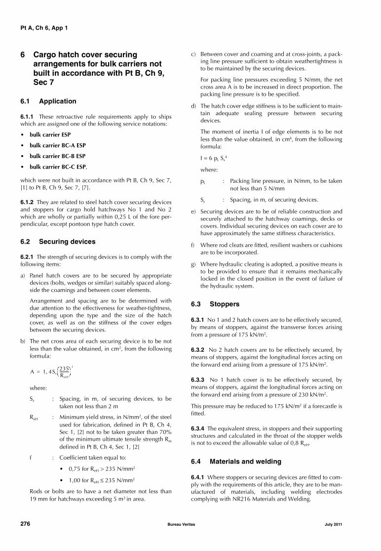
Pt A, Ch 6, App 1
6 Cargo hatch cover securing arrangements for bulk carriers not built in accordance with Pt B, Ch 9, Sec 7
6.1 Application
6.1.1 These retroactive rule requirements apply to shipswhich are assigned one of the following service notations:
• bulk carrier ESP
• bulk carrier BC-A ESP
• bulk carrier BC-B ESP
• bulk carrier BC-C ESP,
which were not built in accordance with Pt B, Ch 9, Sec 7,[1] to Pt B, Ch 9, Sec 7, [7].
6.1.2 They are related to steel hatch cover securing devicesand stoppers for cargo hold hatchways No 1 and No 2which are wholly or partially within 0,25 L of the fore per-pendicular, except pontoon type hatch cover.
6.2 Securing devices
6.2.1 The strength of securing devices is to comply with thefollowing items:
a) Panel hatch covers are to be secured by appropriatedevices (bolts, wedges or similar) suitably spaced along-side the coamings and between cover elements.
Arrangement and spacing are to be determined withdue attention to the effectiveness for weather-tightness,depending upon the type and the size of the hatchcover, as well as on the stiffness of the cover edgesbetween the securing devices.
b) The net cross area of each securing device is to be notless than the value obtained, in cm2, from the followingformula:
where:
Ss : Spacing, in m, of securing devices, to betaken not less than 2 m
ReH : Minimum yield stress, in N/mm2, of the steelused for fabrication, defined in Pt B, Ch 4,Sec 1, [2] not to be taken greater than 70%of the minimum ultimate tensile strength Rm
defined in Pt B, Ch 4, Sec 1, [2]
f : Coefficient taken equal to:
• 0,75 for ReH > 235 N/mm2
• 1,00 for ReH ≤ 235 N/mm2
Rods or bolts are to have a net diameter not less than19 mm for hatchways exceeding 5 m2 in area.
c) Between cover and coaming and at cross-joints, a pack-ing line pressure sufficient to obtain weathertightness isto be maintained by the securing devices.
For packing line pressures exceeding 5 N/mm, the netcross area A is to be increased in direct proportion. Thepacking line pressure is to be specified.
d) The hatch cover edge stiffness is to be sufficient to main-tain adequate sealing pressure between securingdevices.
The moment of inertia I of edge elements is to be notless than the value obtained, in cm4, from the followingformula:
I = 6 pL Ss4
where:
pL : Packing line pressure, in N/mm, to be takennot less than 5 N/mm
Ss : Spacing, in m, of securing devices.
e) Securing devices are to be of reliable construction andsecurely attached to the hatchway coamings, decks orcovers. Individual securing devices on each cover are tohave approximately the same stiffness characteristics.
f) Where rod cleats are fitted, resilient washers or cushionsare to be incorporated.
g) Where hydraulic cleating is adopted, a positive means isto be provided to ensure that it remains mechanicallylocked in the closed position in the event of failure ofthe hydraulic system.
6.3 Stoppers
6.3.1 No 1 and 2 hatch covers are to be effectively secured,by means of stoppers, against the transverse forces arisingfrom a pressure of 175 kN/m2.
6.3.2 No 2 hatch covers are to be effectively secured, bymeans of stoppers, against the longitudinal forces acting onthe forward end arising from a pressure of 175 kN/m2.
6.3.3 No 1 hatch cover is to be effectively secured, bymeans of stoppers, against the longitudinal forces acting onthe forward end arising from a pressure of 230 kN/m2.
This pressure may be reduced to 175 kN/m2 if a forecastle isfitted.
6.3.4 The equivalent stress, in stoppers and their supportingstructures and calculated in the throat of the stopper weldsis not to exceed the allowable value of 0,8 ReH.
6.4 Materials and welding
6.4.1 Where stoppers or securing devices are fitted to com-ply with the requirements of this article, they are to be man-ufactured of materials, including welding electrodescomplying with NR216 Materials and Welding.
A 1 4Ss235ReH
----------⎝ ⎠⎛ ⎞
f
,=
276 Bureau Veritas July 2011

Pt A, Ch 6, App 1
7 Guidance on loading/unloading sequences
7.1
7.1.1 The minimum acceptable number of typicalsequences is:
• one homogeneous full load condition
• one part load condition where relevant, such as blockloading or two port unloading
• one full load alternate hold condition, if the ship isapproved for alternate hold loading.
7.1.2 The shipowner/operator should select actual loading/unloading sequences, where possible, which may be portspecific or typical.
7.1.3 The sequence may be prepared using the onboardloading instrument. The selected loading conditions shouldbe built up step by step from commencement of cargo load-ing to reaching full deadweight capacity. Each time theloading equipment changes position to a new hold definesa step. Each step is to be documented and submitted to theSociety. The printout from the loading instrument is gener-ally acceptable. This allows the actual bending momentsand shear forces to be verified and prevent the permissiblevalues being exceeded. In addition, the local strength ofeach hold may need to be considered during the loading.
7.1.4 For each loading condition a summary of all steps isto be included. This summary is to highlight the essentialinformation for each step such as:
• how much cargo is filled in each hold during the differ-ent steps
• how much ballast is discharged from each ballast tankduring the different steps
• the maximum still water bending moment and shear atthe end of each step
• the ship's trim and draught at the end of each step.
7.1.5 The approved typical loading/unloading sequencesmay be included in the approved loading manual or take theform of an addendum. A copy of the approved typical load-ing/unloading sequences is to be placed onboard the ship.
8 Water level detectors on single hold cargo ships other than bulk carriers
8.1 Application
8.1.1 These retroactive rule requirements apply to shipsindicated in Ch 6, Sec 4, [2.1.1].
8.2 Water level detectors
8.2.1 The water level detectors are to:• give an audible and visual alarm at the navigation
bridge when the water level above the inner bottom inthe cargo hold reaches a height of not less than 0,3 m,and another when such level reaches not more than15% of the mean depth of the cargo hold; and
• be fitted at the aft end of the hold, or above its lowestpart where the inner bottom is not parallel to thedesigned waterline. Where webs or partial watertightbulkheads are fitted above the inner bottom, the Societymay require the fitting of additional detectors.
8.2.2 For ships not provided with double bottom in cargohold, the water level detectors are to:• give an audible and visual alarm at the navigation
bridge when the water level above the bottom in thecargo hold reaches a height of not less than 0,3 m or theheight of the floors at centerline, whichever is the high-est, and another when such level reaches not more than15% of the mean depth of the cargo hold; and
• be fitted at the aft end of the hold, or above its lowestpart where the bottom is not parallel to the designedwaterline. Where webs or partial watertight bulkheadsare fitted above the bottom, the Society may require thefitting of additional detectors.
July 2011 Bureau Veritas 277

Pt A, Ch 6, App 1
278 Bureau Veritas July 2011