Embed Size (px)
Citation preview
European Journal of Engineering Science and Technology
ISSN 2538-9181
______________________________
⁎ Corresponding Author E-Mail Address: [email protected]
2538-9181/ © 2019 EJEST. All rights reserved.
Seismic Behaviour of Point Fixed Glass Façade Systems: State of the
Art Review
Eliana Inca1, Sandra Jordão2, Carlos Rebelo3, Constança Rigueiro4, Rui Simões5
1 E. I. is a PhD Candidate of the ISISE Dep. Eng. Civil, University of Coimbra, Coimbra, Portugal. 2 S. J. is an Assistant Professor of the ISISE Dep. Eng. Civil, University of Coimbra, Coimbra,
Portugal 3 Ca. R. is an Associated Professor of the ISISE Dep. Eng. Civil, University of Coimbra, Coimbra,
Portugal 4 Co. R. is an Adjunct Professor of the Dep. Eng. Civil, Instituto Politécnico Castelo Branco,
Castelo Branco, Portugal 5 R. S. is an Assistant Professor of the ISISE Dep. Eng. Civil, University of Coimbra, Coimbra,
Portugal
ARTICLE INFO ABSTRACT
Keywords:
facade systems, point
fixed glass systems,
structural glass, seismic
action
flat glass has been used for many centuries in wall openings and windows.
It allows light in and broadens the visual horizon, while protecting from the
environmental elements. It also features a good potential for energy savings
during the lifetime of the building. The technological developments it
benefited from, in the last decades, transformed common plate glass into a
stronger material, with safer and more predictable failure and some degree
of post breakage capacity; even pseudo-ductility. For this reason, at present
day, glass is a structural material with established credits. This allows for
new buildings with dematerialized contours: the glass skin buildings; which
are taking over the set in modern cities. There are several types of glass
façade buildings, depending on the system used to fix the glass to the main
structure. Point Fixed Glass Façade Systems (PFGFS) feature an advantage
in terms of architectural expression allowing for greater transparency, since
no mullions and frames are required for additional support, only discrete
point fixing. The design codes for structural glass are still under
development, and one of the aspect that needs further attention is the
behaviour of PFGFS when subjected to seismic action. This aspect is of the
essence in the sense that forensic analysis to past earthquake events showed
that important damage has been observed to GFS due to the in-plane racking
actions. This may have severe costs in terms of human losses and in terms
of economic costs (repair and downtime). The present paper addresses this
theme by presenting an overview of its key aspects, review of past research,
both analytical and experiment for PFGFS under seismic loads, design code
provisions for different countries as well as recommendations for prediction
of racking capacity of Point Fixed Glass Façade Systems. The work
presented in this paper is established in the framework of the ongoing
research project: GF Seismic (FCT POCI-01-0145-FEDER-032539).
European Journal of Engineering Science and Technology, 2 (2):1-15, 2019
1
Introduction
Glass is a sustainable material (basically made from 75% molten sand and 25% chalk soda and
can be 100% recycled [1], it is transparent and slender, and can create the feeling of real contact
with the exterior. Is important to notice that façade systems play an important role in buildings in
order to provide entrance of sun light, air protection, most importantly adequate indoor
environments by controlling comfort and adequate use of energy (both for heating and cooling).
Different materials can be used for façade systems, the selection will depend on the architectural
design of the building, two types of façades can be distinguished [2]: i) Opaque façades,
constructed with layers of solid materials such as masonry, stone, precast concrete panels, metal
(aluminium, stainless steel). ii) Glazed Facades, such as curtain walls or storefront facades,
consisting in translucent glazing material and metal framing as secondary components.
Current tendency for building construction aims to create lighter, bigger and more spacious
facilities, therefore frameless glass façade systems have gained popularity over the past thirty
years, due to their ability to allow high transparency on the building’s façade while using less
elements for the support of the glass panels. The current use of bolted structural glass façades
started with the plate suspended assemblies of the 1960’s and 70’s [3], with the introduction of
Pilkington’s Planar system in 1981 followed by RFR’s La Villete ball-joint systems to nowadays
point fixing techniques. Modern frameless glass façade systems include bolted spider arms
connections, providing a point support on the glass panels usually on the corners of each glass
panel, according to its size intermediate points may be required. Structural supports for these
systems may vary from truss, cable and steel support systems [4]. In general, in a Glass Façade
System (GFS), four basic components may be identified: glazing panels, bolted fixings, glazing
support attachments and the main support structure.
Damage To Glass Façade Systems In Past Earthquakes
Non-structural damage has been constantly reported in past earthquakes [5], investment on non-
structural components in construction (including contents) for a typical office are 82% and for
hospitals up to 92% of total building costs [6], pointing out the great investment there is in non-
structural components and contents rather than structural components and framing. After the San
Fernando earthquake in 1971 (California), where several buildings were reported with glass
damage [7], it became clear that non-structural components can be very vulnerable to strong
shaking, damage to non-structural components not only can be very costly but also can pose real
threat to life safety, therefore reducing damage to those elements has been an important
engineering task for the past decades.
From the 1985 Mexico City strong earthquake some lessons were learned on glass damage,
window glass falling was the second most serious non-structural damage well documented [8]. On
the latest strong earthquake on 19th September 2017 Puebla, Mexico, damage was reported on
medium high buildings (8-12 stories) and mostly due to structural irregularities, important non-
structural damage was observed on in-fill walls (masonry facades of buildings were severely
damaged) and glass window falling according [9].
An important correlation between the inter-storey drift and the glass damage was reported on
several post-earthquake damage assessments [10]. Flexible glass façade systems enclosed by metal
curtain walls and mullions presented less damage in past seismic events [11], mainly due to the
high deformability of silicon allowing for a better accommodation of drift demand during ground
shaking. Further, it is reported that glass damage consistently increases with larger window areas
and irregular plan configurations [12]. Therefore, due to the significant increase of glass usage in
European Journal of Engineering Science and Technology, 2 (2):1-15, 2019
2
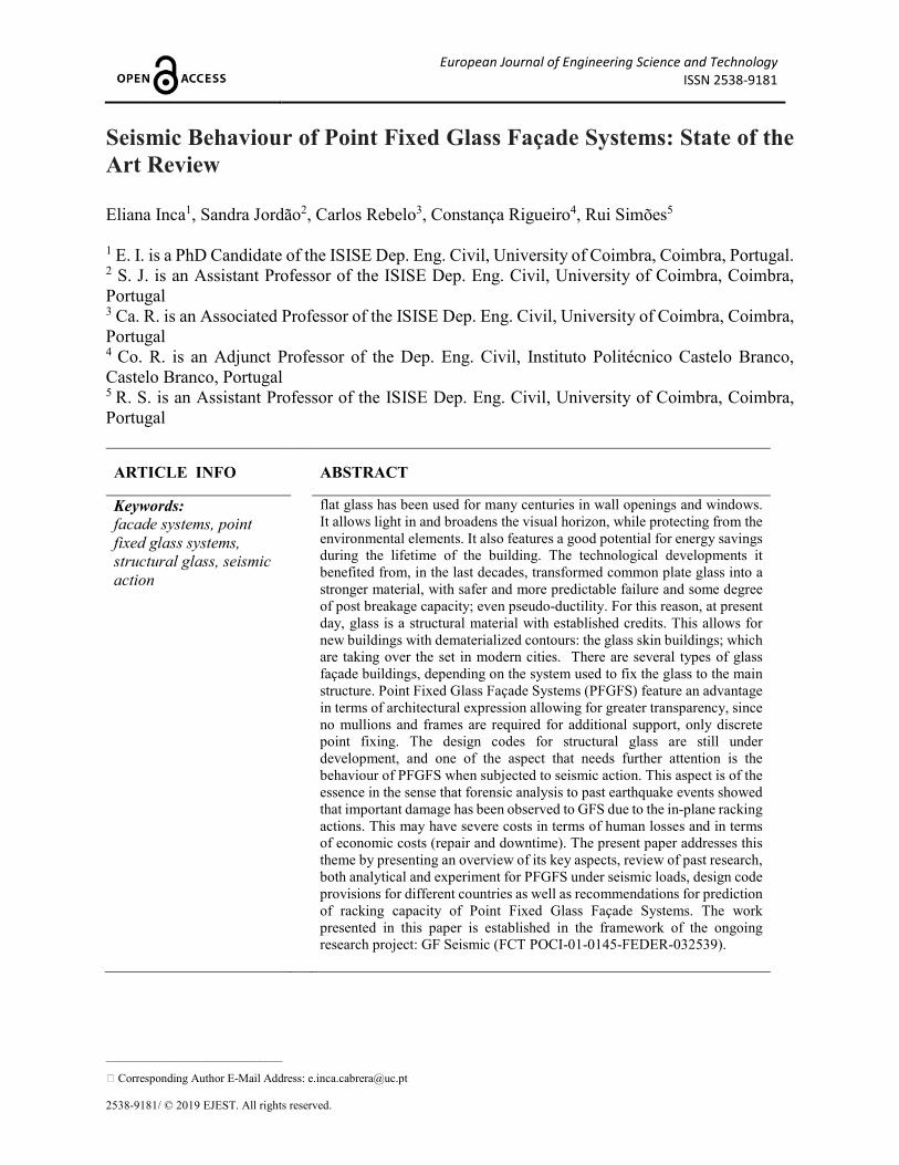
buildings, an increasing interest rise about controlling their possible damage. An example of
curtain glazing falling out is shown in figure 1.
Fig. 1. Kaiser Permanetate Building, Granada Hills, California, cladding offset [6].
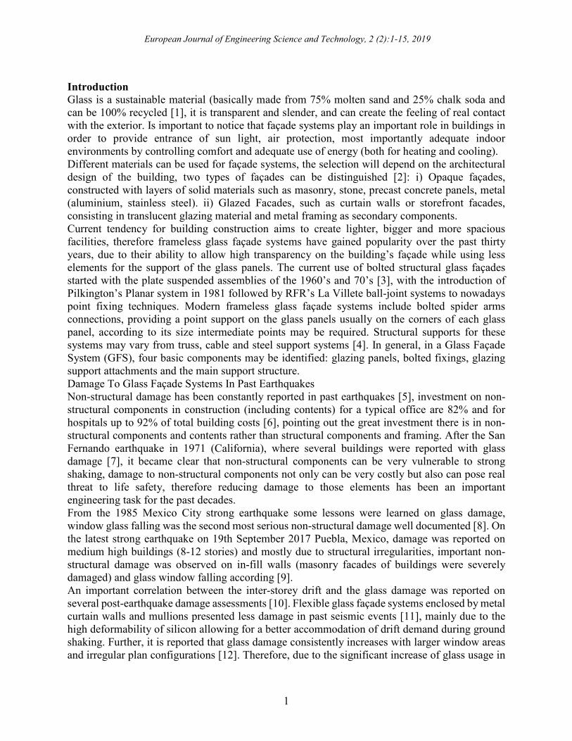
A damage extent report of the Christchurch earthquake in 2011 (New Zeeland,) showed that heavy
damage was observed in spider glazing [10], as can be seen in figure 2, this behaviour was
originated around the “spider” that holds each glass pane, likely a result of the “spider” creating
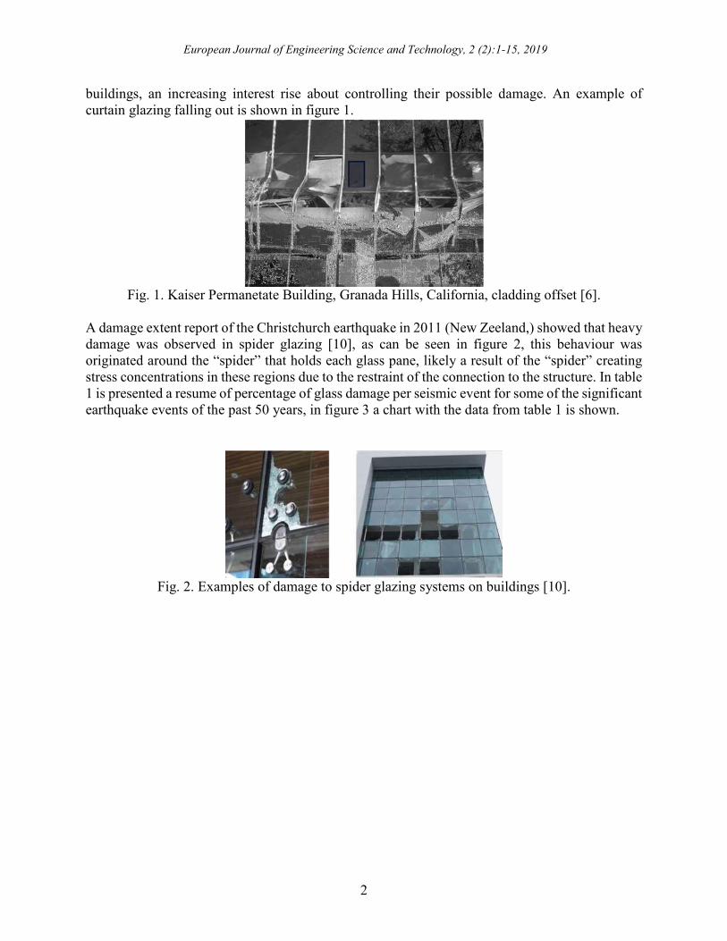
stress concentrations in these regions due to the restraint of the connection to the structure. In table
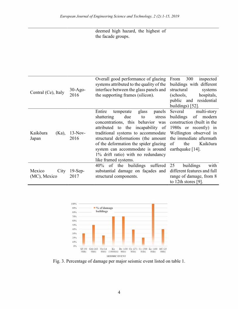
1 is presented a resume of percentage of glass damage per seismic event for some of the significant
earthquake events of the past 50 years, in figure 3 a chart with the data from table 1 is shown.
Fig. 2. Examples of damage to spider glazing systems on buildings [10].
European Journal of Engineering Science and Technology, 2 (2):1-15, 2019
3
TABLE I: DESCRIPTION OF PERCENTAGE OF DAMAGED GLASS FAÇADES ON PAST
EARTHQUAKES.
SEISMIC
EVENT DATE
REPORTED DAMAGE ON
FACADES DATA
San Fernando
(SF), California,
USA
9-Feb-
1971
30 % of building’s façades sustained
broken glass
50 high rise buildings in
locations away from the
epicenter [49; 50].
Guerrero-
Michoacan (GM),
Mexico
19-Sep-
1985
50% of buildings with structural
damage presented glass damage.
25% of buildings presented serious
damage and glass falling.
263 multi-story office
buildings [8; 49].
Northridge (No),
California, USA
17-En-
1994
25% of the storefront windows
presented damage
Over 14 buildings with
limited non-structural
damage and no structural
damage reported in
downtown Bunbank
[49].
CW systems in general performed
well, damage was more frequent for
low-rise storefront windows.
High rise curtain walls
systems.
Kobe (Ko), Japan 17-Jan-95
General glass fracture and
deformation on glazing frames,
differences were observed in façade
orientation, southerly oriented
glazing panels were damage above
70% in comparison to northerly
façades with less than 15% damage.
Several buildings were
asses, low (up to 60 m
height) to height
buildings (above 60m
height) [49].
Tall buildings didn't showed
representative structural damage nor
major glazing damage.
Bam (Ba), Iran 26-Dec-
2003
70 % buildings of the area were
destroyed and buildings with no
significant structural damage
presented important non-structural
damage (glass fallout).
Field investigation in
Bam epicenter town of
several medium to height
buildings [13].
Christchurch (Ch),
New Zeland
22-Feb-
2011
The glass damage was recorded for all
lightweight cladding that contained
glass. Nearly half of all glazed
lightweight claddings had glazing
damage and 39% presented a falling
hazard. Only 60% of infill systems
were deemed either operational or
immediate occupancy. 17% were
371 façade systems on
271 buildings were
surveyed [10].
European Journal of Engineering Science and Technology, 2 (2):1-15, 2019
4
deemed high hazard, the highest of
the facade groups.
Central (Ce), Italy 30-Ago-
2016
Overall good performance of glazing
systems attributed to the quality of the
interface between the glass panels and
the supporting frames (silicon).
From 300 inspected
buildings with different
structural systems
(schools, hospitals,
public and residential
buildings) [52].
Kaikōura (Ka),
Japan
13-Nov-
2016
Entire temperate glass panels
shattering due to stress
concentrations, this behavior was
attributed to the incapability of
traditional systems to accommodate
structural deformations (the amount
of the deformation the spider glazing
system can accommodate is around
1% drift ratio) with no redundancy
like framed systems.
Several multi-story
buildings of modern
construction (built in the
1980s or recently) in
Wellington observed in
the immediate aftermath
of the Kaikōura
earthquake [14].
Mexico City
(MC), Mexico
19-Sep-
2017
40% of the buildings suffered
substantial damage on façades and
structural components.
25 buildings with
different features and full
range of damage, from 8
to 12th stores [9].
Fig. 3. Percentage of damage per major seismic event listed on table 1.
European Journal of Engineering Science and Technology, 2 (2):1-15, 2019
5
Structural Façade Configuration For Point Fixed Glass Façade Systems
Different point fixed glass façade systems (PFGFS) were developed due to architectural
requirements, over time, industry evolved according to market necessities, even though glass
façade systems are not standardized, four basic components can be identified for bolted glazing
systems and are explained below: glazing panels, bolted fixings, glazing support attachments and
main support structure.
Glazing Panels
Usually toughened glass and laminated glass are the most common types of glass panels used for
façades. Toughened glass induces a favourable tension field all over the surface of the glass panels
due to a process of heating the panels at high temperatures (600ºc-650ºC) followed by a rapidly
cooling process, allowing balanced stress condition across the thickness of the glass panel, one
important property of this type of glass panels is the capacity of fragmenting into small particles
after fracture.
Laminated glass, on the other hand, is produced by a process of bonding two or more layers of
glass with an intermediate interlayer. The most popular interlayer is PVB (polyvinyl butyral), other
type of interlayers are: Ethylene Vinyl Acetate EVA or SentryGlass (SG). Commonly known as
safety glass, when subjected to sufficient impact to break the glass, fragments typically remain
intact, firmly adhered to the PVB interlayer [15]. Depending on factors like shape, size of glass,
edge treatment, quality of holes, etc. Resistance of the glass panel will vary, for point fix glass,
stresses near the holes and glass thickness will determine the resistance of the panels and final
design will take into account panel deflection.
Bolted Fixings
Bolted fixings provide point support to the glass panels and transfer the glass self-weight and
lateral loads to the structural support. The bolted fixings are usually located towards the corners of
the glass panels and additionally at intermediate points on long edges. Several types of bolts exist:
enhanced countersunk fixings (allow to transfer out of plane and in plane loads directly through to
the bolt and glass interface), articulated bolts fixings (allow for accommodate rotation of the fixing
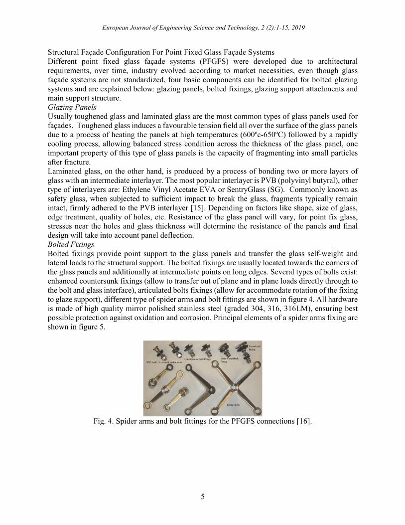
to glaze support), different type of spider arms and bolt fittings are shown in figure 4. All hardware
is made of high quality mirror polished stainless steel (graded 304, 316, 316LM), ensuring best
possible protection against oxidation and corrosion. Principal elements of a spider arms fixing are
shown in figure 5.
Fig. 4. Spider arms and bolt fittings for the PFGFS connections [16].
European Journal of Engineering Science and Technology, 2 (2):1-15, 2019
6
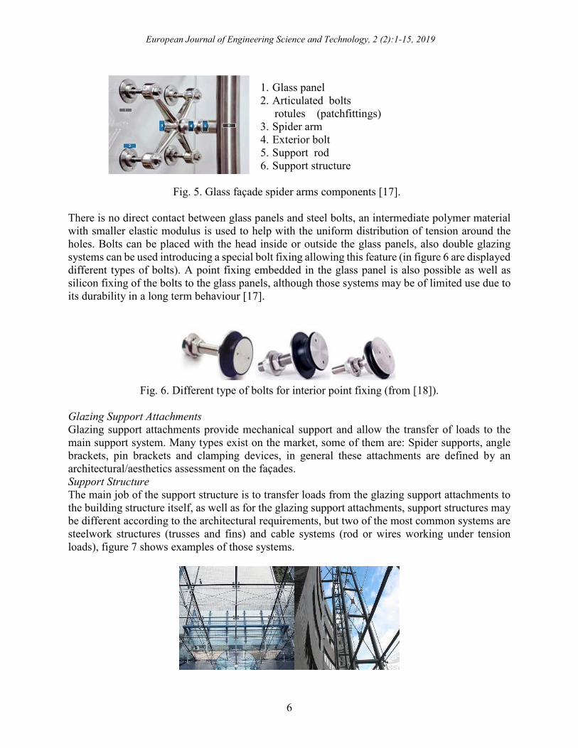
1. Glass panel
2. Articulated bolts
rotules (patchfittings)
3. Spider arm
4. Exterior bolt
5. Support rod
6. Support structure
Fig. 5. Glass façade spider arms components [17].
There is no direct contact between glass panels and steel bolts, an intermediate polymer material
with smaller elastic modulus is used to help with the uniform distribution of tension around the
holes. Bolts can be placed with the head inside or outside the glass panels, also double glazing
systems can be used introducing a special bolt fixing allowing this feature (in figure 6 are displayed
different types of bolts). A point fixing embedded in the glass panel is also possible as well as
silicon fixing of the bolts to the glass panels, although those systems may be of limited use due to
its durability in a long term behaviour [17].
Fig. 6. Different type of bolts for interior point fixing (from [18]).
Glazing Support Attachments
Glazing support attachments provide mechanical support and allow the transfer of loads to the
main support system. Many types exist on the market, some of them are: Spider supports, angle
brackets, pin brackets and clamping devices, in general these attachments are defined by an
architectural/aesthetics assessment on the façades.
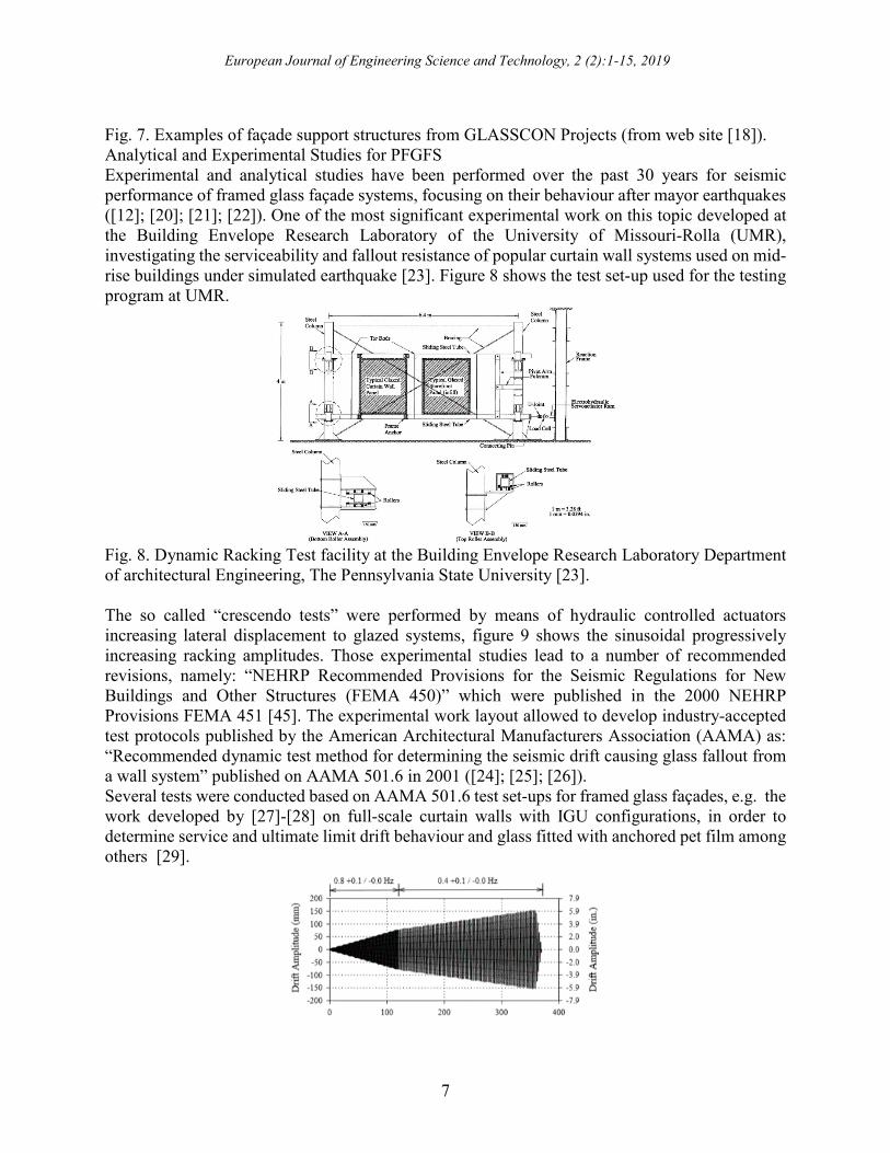
Support Structure
The main job of the support structure is to transfer loads from the glazing support attachments to
the building structure itself, as well as for the glazing support attachments, support structures may
be different according to the architectural requirements, but two of the most common systems are
steelwork structures (trusses and fins) and cable systems (rod or wires working under tension
loads), figure 7 shows examples of those systems.
European Journal of Engineering Science and Technology, 2 (2):1-15, 2019
7
Fig. 7. Examples of façade support structures from GLASSCON Projects (from web site [18]).
Analytical and Experimental Studies for PFGFS
Experimental and analytical studies have been performed over the past 30 years for seismic
performance of framed glass façade systems, focusing on their behaviour after mayor earthquakes
([12]; [20]; [21]; [22]). One of the most significant experimental work on this topic developed at
the Building Envelope Research Laboratory of the University of Missouri-Rolla (UMR),
investigating the serviceability and fallout resistance of popular curtain wall systems used on mid-
rise buildings under simulated earthquake [23]. Figure 8 shows the test set-up used for the testing
program at UMR.
Fig. 8. Dynamic Racking Test facility at the Building Envelope Research Laboratory Department
of architectural Engineering, The Pennsylvania State University [23].
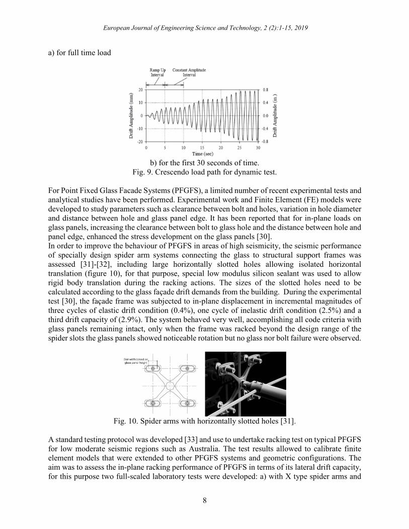
The so called “crescendo tests” were performed by means of hydraulic controlled actuators
increasing lateral displacement to glazed systems, figure 9 shows the sinusoidal progressively
increasing racking amplitudes. Those experimental studies lead to a number of recommended
revisions, namely: “NEHRP Recommended Provisions for the Seismic Regulations for New
Buildings and Other Structures (FEMA 450)” which were published in the 2000 NEHRP
Provisions FEMA 451 [45]. The experimental work layout allowed to develop industry-accepted
test protocols published by the American Architectural Manufacturers Association (AAMA) as:
“Recommended dynamic test method for determining the seismic drift causing glass fallout from
a wall system” published on AAMA 501.6 in 2001 ([24]; [25]; [26]).
Several tests were conducted based on AAMA 501.6 test set-ups for framed glass façades, e.g. the
work developed by [27]-[28] on full-scale curtain walls with IGU configurations, in order to
determine service and ultimate limit drift behaviour and glass fitted with anchored pet film among
others [29].
European Journal of Engineering Science and Technology, 2 (2):1-15, 2019
8
a) for full time load
b) for the first 30 seconds of time.
Fig. 9. Crescendo load path for dynamic test.
For Point Fixed Glass Facade Systems (PFGFS), a limited number of recent experimental tests and
analytical studies have been performed. Experimental work and Finite Element (FE) models were
developed to study parameters such as clearance between bolt and holes, variation in hole diameter
and distance between hole and glass panel edge. It has been reported that for in-plane loads on
glass panels, increasing the clearance between bolt to glass hole and the distance between hole and
panel edge, enhanced the stress development on the glass panels [30].
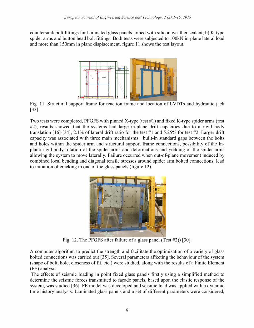
In order to improve the behaviour of PFGFS in areas of high seismicity, the seismic performance
of specially design spider arm systems connecting the glass to structural support frames was
assessed [31]-[32], including large horizontally slotted holes allowing isolated horizontal
translation (figure 10), for that purpose, special low modulus silicon sealant was used to allow
rigid body translation during the racking actions. The sizes of the slotted holes need to be
calculated according to the glass façade drift demands from the building. During the experimental
test [30], the façade frame was subjected to in-plane displacement in incremental magnitudes of
three cycles of elastic drift condition (0.4%), one cycle of inelastic drift condition (2.5%) and a
third drift capacity of (2.9%). The system behaved very well, accomplishing all code criteria with
glass panels remaining intact, only when the frame was racked beyond the design range of the
spider slots the glass panels showed noticeable rotation but no glass nor bolt failure were observed.
Fig. 10. Spider arms with horizontally slotted holes [31].
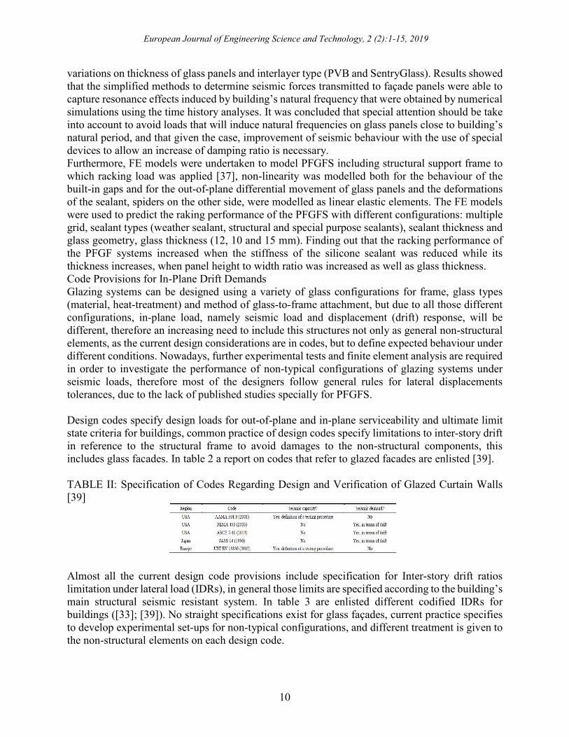
A standard testing protocol was developed [33] and use to undertake racking test on typical PFGFS
for low moderate seismic regions such as Australia. The test results allowed to calibrate finite
element models that were extended to other PFGFS systems and geometric configurations. The
aim was to assess the in-plane racking performance of PFGFS in terms of its lateral drift capacity,
for this purpose two full-scaled laboratory tests were developed: a) with X type spider arms and
European Journal of Engineering Science and Technology, 2 (2):1-15, 2019
9
countersunk bolt fittings for laminated glass panels joined with silicon weather sealant, b) K-type
spider arms and button head bolt fittings. Both tests were subjected to 100kN in-plane lateral load
and more than 150mm in plane displacement, figure 11 shows the test layout.
Fig. 11. Structural support frame for reaction frame and location of LVDTs and hydraulic jack
[33].
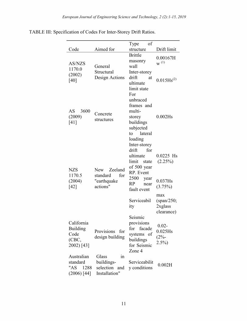
Two tests were completed, PFGFS with pinned X-type (test #1) and fixed K-type spider arms (test
#2), results showed that the systems had large in-plane drift capacities due to a rigid body
translation [16]-[34], 2.1% of lateral drift ratio for the test #1 and 5.25% for test #2. Larger drift
capacity was associated with three main mechanisms: built-in standard gaps between the bolts
and holes within the spider arm and structural support frame connections, possibility of the In-
plane rigid-body rotation of the spider arms and deformations and yielding of the spider arms
allowing the system to move laterally. Failure occurred when out-of-plane movement induced by
combined local bending and diagonal tensile stresses around spider arm bolted connections, lead
to initiation of cracking in one of the glass panels (figure 12).
Fig. 12. The PFGFS after failure of a glass panel (Test #2)) [30].
A computer algorithm to predict the strength and facilitate the optimization of a variety of glass
bolted connections was carried out [35]. Several parameters affecting the behaviour of the system
(shape of bolt, hole, closeness of fit, etc.) were studied, along with the results of a Finite Element
(FE) analysis.
The effects of seismic loading in point fixed glass panels firstly using a simplified method to
determine the seismic forces transmitted to façade panels, based upon the elastic response of the
system, was studied [36]. FE model was developed and seismic load was applied with a dynamic
time history analysis. Laminated glass panels and a set of different parameters were considered,
European Journal of Engineering Science and Technology, 2 (2):1-15, 2019
10
variations on thickness of glass panels and interlayer type (PVB and SentryGlass). Results showed
that the simplified methods to determine seismic forces transmitted to façade panels were able to
capture resonance effects induced by building’s natural frequency that were obtained by numerical
simulations using the time history analyses. It was concluded that special attention should be take
into account to avoid loads that will induce natural frequencies on glass panels close to building’s
natural period, and that given the case, improvement of seismic behaviour with the use of special
devices to allow an increase of damping ratio is necessary.
Furthermore, FE models were undertaken to model PFGFS including structural support frame to
which racking load was applied [37], non-linearity was modelled both for the behaviour of the
built-in gaps and for the out-of-plane differential movement of glass panels and the deformations
of the sealant, spiders on the other side, were modelled as linear elastic elements. The FE models
were used to predict the raking performance of the PFGFS with different configurations: multiple
grid, sealant types (weather sealant, structural and special purpose sealants), sealant thickness and
glass geometry, glass thickness (12, 10 and 15 mm). Finding out that the racking performance of
the PFGF systems increased when the stiffness of the silicone sealant was reduced while its
thickness increases, when panel height to width ratio was increased as well as glass thickness.
Code Provisions for In-Plane Drift Demands
Glazing systems can be designed using a variety of glass configurations for frame, glass types
(material, heat-treatment) and method of glass-to-frame attachment, but due to all those different
configurations, in-plane load, namely seismic load and displacement (drift) response, will be
different, therefore an increasing need to include this structures not only as general non-structural
elements, as the current design considerations are in codes, but to define expected behaviour under
different conditions. Nowadays, further experimental tests and finite element analysis are required
in order to investigate the performance of non-typical configurations of glazing systems under
seismic loads, therefore most of the designers follow general rules for lateral displacements
tolerances, due to the lack of published studies specially for PFGFS.
Design codes specify design loads for out-of-plane and in-plane serviceability and ultimate limit
state criteria for buildings, common practice of design codes specify limitations to inter-story drift
in reference to the structural frame to avoid damages to the non-structural components, this
includes glass facades. In table 2 a report on codes that refer to glazed facades are enlisted [39].
TABLE II: Specification of Codes Regarding Design and Verification of Glazed Curtain Walls
[39]
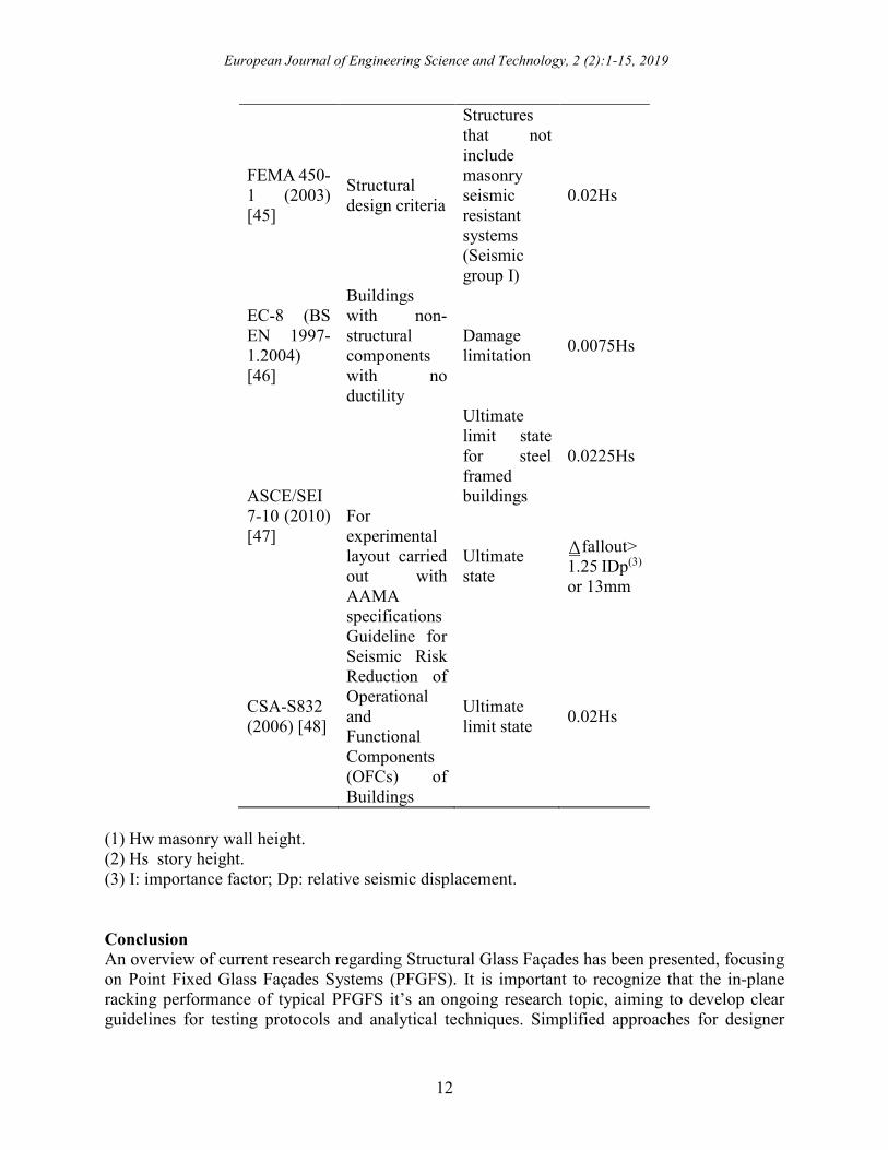
Almost all the current design code provisions include specification for Inter-story drift ratios
limitation under lateral load (IDRs), in general those limits are specified according to the building’s
main structural seismic resistant system. In table 3 are enlisted different codified IDRs for
buildings ([33]; [39]). No straight specifications exist for glass façades, current practice specifies
to develop experimental set-ups for non-typical configurations, and different treatment is given to
the non-structural elements on each design code.
European Journal of Engineering Science and Technology, 2 (2):1-15, 2019
11
TABLE III: Specification of Codes For Inter-Storey Drift Ratios.
Code Aimed for
Type of
structure Drift limit
AS/NZS
1170.0
(2002)
[40]
General
Structural
Design Actions
Brittle
masonry
wall
0.00167H
w (1)
Inter-storey
drift at
ultimate
limit state
0.015Hs(2)
AS 3600
(2009)
[41]
Concrete
structures
For
unbraced
frames and
multi-
storey
buildings
subjected
to lateral
loading
0.002Hs
NZS
1170.5
(2004)
[42]
New Zeeland
standard for
"earthquake
actions"
Inter-storey
drift for
ultimate
limit state
of 500 year
RP. Event
0.0225 Hs
(2.25%)
2500 year
RP near
fault event
0.037Hs
(3.75%)
Serviceabil
ity
max
(span/250;
2xglass
clearance)
California
Building
Code
(CBC,
2002) [43]
Provisions for
design building
Seismic
provisions
for facade
systems of
buildings
for Seismic
Zone 4
0.02-
0.025Hs
(2%-
2.5%)
Australian
standard
"AS 1288
(2006) [44]
Glass in
buildings-
selection and
Installation"
Serviceabilit
y conditions 0.002H
European Journal of Engineering Science and Technology, 2 (2):1-15, 2019
12
FEMA 450-
1 (2003)
[45]
Structural
design criteria
Structures
that not
include
masonry
seismic
resistant
systems
(Seismic
group I)
0.02Hs
EC-8 (BS
EN 1997-
1.2004)
[46]
Buildings
with non-
structural
components
with no
ductility
Damage
limitation 0.0075Hs
ASCE/SEI
7-10 (2010)
[47]
Ultimate
limit state
for steel
framed
buildings
0.0225Hs
For
experimental
layout carried
out with
AAMA
specifications
Ultimate
state
⍙fallout>
1.25 IDp(3)
or 13mm
CSA-S832
(2006) [48]
Guideline for
Seismic Risk
Reduction of
Operational
and
Functional
Components
(OFCs) of
Buildings
Ultimate
limit state 0.02Hs
(1) Hw masonry wall height.
(2) Hs story height.
(3) I: importance factor; Dp: relative seismic displacement.
Conclusion
An overview of current research regarding Structural Glass Façades has been presented, focusing
on Point Fixed Glass Façades Systems (PFGFS). It is important to recognize that the in-plane
racking performance of typical PFGFS it’s an ongoing research topic, aiming to develop clear
guidelines for testing protocols and analytical techniques. Simplified approaches for designer
European Journal of Engineering Science and Technology, 2 (2):1-15, 2019
13
engineers are required to be developed as well as clear code specifications as it has been developed
for Curtain Wall Façades Systems.
Acknowledgment
Financial support from the Portuguese Foundation for Sciences and Technology (Fundação da
Ciência e Tecnologia) under contract grant POCI-01-0145-FEDER-032539 (GF-Seismic |
Structural Glass Facades Subjected to Seismic Load) is gratefully acknowledged.
References
[1] R. Nijsse, “The Future of all glass structures”, In Proceedings of IASS Annual Symposia, pp.
1-7, vol. 2015.
[2] A. Aksamija, “Sustainable Façades: Design Methods for High-Performance Building
Envelopes”, John Wiley and Sons, Hoboken, New Jersey, 2013.
[3] G. Dodd, “Essential elements of bolted structural glass systems”. Proceedings of the
International Conference in Building Envelope Systems and Technology, Centre for Window
& Cladding Technology (ICBEST’97), eds. S. Ledbetter, R. Harris, p. 92, vol. 76, 1997.
[4] P. Ryan, O. Mike and R. G. Ogden. “Steel supported glazing systems”. Steel Construction
Institute, Ascot, UK, 1997.
[5] A.S. Whittaker and T.T. Soong, “An overview of non-structural components research at three
US Earthquake Engineering Center”. Proceedings of ATC-29-2 Seminar on Seismic design,
Performance and Retrofit of Non-Structural components in Critical Facilities, p. 271-280,
Berkeley, CA, 2003.
[6] S. Taghavi and E. Miranda. “Response assessment of nonstructural building elements,” Pacific
Earthquake Engineering Research Center, 2003
[7] P. C. Jennings, “Enduring lessons and opportunities lost from the San Fernando earthquake of
February 9, 1971,” Earthquake spectra, vol. 13, no. 1, pp. 25-44, 1997.
[8] D. Evans, E. Kennett, W. T. Holmes and F. J. L. Ramirez, “Glass damage in the September
19, 1985 Mexico City earthquake”. Rep. Prepared for NSF, CES, 861093, 1988.
[9] S. Roeslin, Q. T. M. Ma and H. Juárez, “Damage Assessment on Buildings following the 19th
September 2017 Puebla, Mexico Earthquake,” Frontiers in Built Environment, vol. 4, p. 72,
2018.
[10] A. Baird, A. Palermo and S. Pampanin, “Facade damage assessment of multi-storey
buildings in the 2011 Christchurch earthquake,” Bulletin of the New Zealand Society for
earthquake engineering, vol. 44, no 4, p. 368-376, 2011.
[11] D. Perrone, P. M. Calvi, R. Nascimbene, E. C. Fischer and G. Magliulo, “Seismic
performance of non-structural elements during the 2016 Central Italy earthquake”, Bulletin of
Earthquake Engineering, 2018, p. 1-23, 2018.
[12] H. Sucuoǧlu and C. G. Vallabhan, “Behaviour of window glass panels during
earthquakes”. Engineering structures, vol. 19, no 8, p. 685-694, 1997.
[13] M. Hosseini, “Behavior of nonstructural elements in the 2003 Bam, Iran, earthquake,”
Earthquake Spectra, vol. 21, no S1, p. 439-453, 2005.
[14] A. Baird, and H. Ferner, “Damage to non‐structural elements in the 2016 Kaikōura
earthquake”. Bull. New Zeal. Soc. Earthq. Eng., no 2, p. 187-193, 2017.
[15] G. James is glass Handbook, G. James Australia Pty Ltd., Australia, 2000.
[16] S. Sivanerupan, J. L. Wilson, E. F. Gad and N. T. K. Lam, “In-plane drift capacity of
contemporary point fixed glass façade systems,” Journal of Architectural Engineering, 2013,
vol. 20, no 1, 2013.
European Journal of Engineering Science and Technology, 2 (2):1-15, 2019
14
[17] C. Silveira, “Controlo da Qualidade de Fachadas em Vidrio Fachadas-Cortina e Fachadas
em Vidrio Exterior Agrafado,” Master dissertation, Dept. Civil. Eng., IST Técnico Lisboa,
Lisboa, Portugal, 2018.
[18] Fitechnic website: https://www.glasscon.com/projects/ceramic-cladding-spider-glass-
curtain-wall-tension-rod.
[19] GLASSCON website: https://www.glasscon.com/projects/ceramic-cladding-spider-glass-
curtain-wall-tension-rod.
[20] I. Sakamoto, “Seismic performance of nonstructural and secondary structural elements,”
University of California, Earthquake Engineering Research Center, Rep. No. EERC-78/10,
1978.
[21] R. A. Behr, A. Belarbi and A. T. Brown, “Seismic performance of architectural glass in a
storefront wall system”. Earthquake Spectra, vol. 11, no 3, p. 367-391, 1995.
[22] K. Y. S. Lim and A. B. King, “The behaviour of external glazing systems under seismic
in-plane racking”. BRANZ, 1991.
[23] R. A. Behr, “Seismic performance of architectural glass in mid-rise curtain wall,” Journal
of Architectural Engineering, vol. 4, no 3, p. 94-98, 1998.
[24] Recommended static test method for evaluating curtain wall and storefront systems
subjected to seismic and wind induced inter-story drifts, Publication No. AAMA 501.4-01-
2001a.
[25] Recommended dynamic test method for determining the seismic drift causing glass fallout
from a wall system, Publication No. AAMA 501.6-01-2001b.
[26] R. A. Behr, “Design of architectural glazing to resist earthquakes,” Journal of architectural
engineering, 2006, vol. 12, no 3, p. 122-128.
[27] A. M. Memari, R. A. Behr, R. A. And P. A. Kremer, “Seismic behaviour of curtain walls
containing insulating glass units,” Journal of architectural engineering, vol. 9, no 2, p. 70-85,
2003.
[28] A. M. Memari, R. A. Behr, R. A. And P. A. Kremer, “Dynamic racking crescendo tests on
architectural glass fitted with anchored pet film,” Journal of Architectural Engineering, vol.
10, no 1, p. 5-14, 2004.
[29] C. Bedon, X. Zhang, F. Santos, D. Honfi, M. Kozłowski, M. Arrigoni and D. Lange,
“Performance of structural glass facades under extreme loads–Design methods, existing
research, current issues and trends,” Construction and Building Materials, vol. 163, p. 921-
937, 2018.
[30] I. Maniatis, “Numerical and experimental investigations on the stress distribution of bolted
glass connections under in-plane loads,” Ph.D. dissertation, Technische Universität München,
2006.
[31] P. Desai, A. Golmohammadi, R. Garlipp and B. Gowda, “New point supported glass
seismic system,” Proceedings of the First International Conference on Advances in
Experimental Structural Engineering (AESE 2005), Nagoya, Japan, 2005.
[32] B. Gowda and N. Heydari, “High displacement glass seismic systems”, Practice Periodical
on Structural Design and Construction, ASCE, Vol. 15, No. 2, pp. 170–176, 2009.
[33] S. Sivanerupan, “In-plane seismic performance of glass facade systems,” Ph.D.
dissertation, University of Technology, Victoria, Australia, 2011.
[34] S. Sivanerupan, J. L. Wilson, E. F. Gad, E. F., and N. T. K. Lam, “Drift performance of
point fixed glass façade systems,” Advances in Structural Engineering, vol. 17, no 10, p.
1481-1495, 2014.
European Journal of Engineering Science and Technology, 2 (2):1-15, 2019
15
[35] M. Overend, “Optimizing connections in structural glass,” In Proceedings of 2nd
International conference on Glass in Buildings, 2005.
[36] L. Martins, R. Delgado, R. Camposinhos, and T. Silva, “Seismic Behaviour of Point
Supported Glass Panels,” Challenging Glass 3: Conference on Architectural and Structural
Applications of Glass, Faculty of Civil Engineering and Geosciences, Delft University of
Technology, p. 281, June, 2012.
[37] S. Sivanerupan, J. L. Wilson, E. F. Gad, E. F., and N. T. K. Lam, “Analytical study of
point fixed glass façade systems under monotonic in-plane loading,” Advances in Structural
Engineering, vol. 19, no 4, p. 611-626, 2016.
[38] N. Caterino, M. Del Zoppo, G. Maddaloni, A. Bonati, G. Cavanna and A. Occhiuzzi,
“Seismic assessment and finite element modelling of glazed curtain walls” Structural
Engineering and Mechanics, vol. 61, no 1, p. 77-90, 2017.
[39] B. Huang, S. Chen, W. Lu and K. M. Mosalam, “Seismic demand and experimental
evaluation of the nonstructural building curtain wall: A review,” Soil Dynamics and
Earthquake Engineering, vol. 100, p. 16-33, 2017.
[40] Structural design actions, Part 0: General principles, Australian/New Zealand Standard -
AS/NZS1170.0-2002.
[41] Concrete structures, Australian Standard - AS3600-2009
[42] Structural design actions, Part 5: Earthquake actions. New Zealand Standard NZS 1170.5-
2004.
[43] California building code: California code of regulations, Title 24, Part 2 (Volume 1), CBC-
2002
[44] Glass in buildings -Selection and installation. Australian Standard AS1288-2006.
[45] NEHRP Recommended Provisions for Seismic Regulations for new Buildings and Other
structures, Part 1: provisions, FEMA 450-2003.
[46] Eurocode 8: design of structures for earthquake resistance- Part 1: general rules, seismic
actions and rules for buildings, BS EN 1998-1-2004.
[47] Minimum design loads for buildings and other structure, ASCE7-10-2010
[48] Guideline for seismic risk reduction of operational and functional components (OFCs) of
buildings, CSA-S832-2006.
[49] R. A. Behr, Architectural glass to resist seismic and extreme climatic events; Cambridge,
U. K.: Woodhead Publishing Limited, 2009, ch. 2, pp. 36-51.
[50] P. C. Jennings, “Enduring Lessons and Opportunities Lost from the San Fernando
Earthquake of February 9, 1971,” Earthquake Spectra vol. 13, no 1, pp. 25-44, 1997.
[51] EEFIT, “The Hyogo-Ken Nanbu (Kobe) Earthquake of 17 January 1995,” Earthquake
Engineering Field Investigation Team pp. 4.1-4.42, March, 1997.
[52] D. Perrone, P. M. Calvi, R. Nascimbene, E. C. Fisher and G. Magliulo “Seismic
Performance of non-structural elements during the 2016 Central Italy earthquake,” Bulletin of
Earthquake Engineering, pp. 1-23, 2018.