Embed Size (px)
Citation preview
1 2 3 4 3
678
10
9
4 5
1. Spolarvätska. Se till att behållaren alltid ärvälfylld. På vintern med frostskydd! Se sidan 142.
2. Servostyrning. Nivån skall ligga mellan MIN- och MAX markeringarna. Se sidan 143.
3. Kylvätskan. Nivån skall ligga mellan MIN- och MAX markeringarna på expansionstanken.Se sidan 142.
4. Oljenivån. Nivån skall ligga mellan marke-garna på mätstickan. Se sidan 141.
5. Bromsvätskenivån. Nivån skall ligga mellan MIN- och MAX markeringarna. Se sidan 141. 1. Blinker H21W (orange)
2. Helljus 55W H7
3. Positions/parkeringsljus W5W
4. Halvljus 55W H7
5. Dimstrålkastare 55W H1
6. Dimljus, bak 21W BA5
7. Backljus 21W BA15
8. Positions/parkeringsljusoch bakljus P21 4W
9. Blinker PY21W (orange)
10. Bromsljus 21W BA15
GlödlamporKontrollera regelbundet
INS
TR
UK
TIO
NS
BO
K V
OL
VO
XC
90
T
P 6
74
9
TP 6749 (Swedish) AT0346 3.300.10.03 Printed in Sweden, TElanders Graphic Systems AB, Göteborg 2003
XC90VOLVO
2004
52930 XC90 Svensk.indd 1 2003-09-12, 07.09.41
WEB EDITION
Volvo ServiceCertain service measures, which affect the car’s electrical system, can only be carried out using electronic equipment specially developed for your car. Always contact your Volvo workshop before beginning or carrying out service work which affects the electrical system.
Installing accessoriesIncorrect connection and installation of accessories can negatively affect the car’s electrical system. Certain acces-sories only function when the appropriate software has been programmed into the car’s electrical system. Always contact your Volvo workshop before installing accessories which are connected to or affect the electrical system.
Recording vehicle dataOne or several of the computers in your Volvo are capable of recording detailed information which may include specific – without being limited to – details regarding; frequency of seat belt use by the driver and passenger, infor-mation on various vehicle system/module functions and information regarding engine, throttle, steering, brakes and other system status.
This information may include details regarding the manner in which the driver operates the vehicle. This type of infor-mation can include specific – without being limited to – details regarding vehicle speed, use of the brakes, accelerator pedal or steering wheel position. This information can be stored while the car is being driven, during a collision or a near-collision.
The stored information may be read and used by:
• Volvo Car Corporation
• Service and repair facilities
• Police and other authorities
• Other interested parties who are entitled – or receive your permission for – access to this information.
52932 XC90 Eng indd 2 2003 09 12 10 01 46
1
Introduction
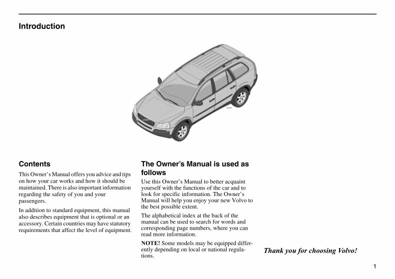
ContentsThis Owner’s Manual offers you advice and tips on how your car works and how it should be maintained. There is also important information regarding the safety of you and your passengers.
In addition to standard equipment, this manual also describes equipment that is optional or an accessory. Certain countries may have statutory requirements that affect the level of equipment.
The Owner’s Manual is used as followsUse this Owner’s Manual to better acquaint yourself with the functions of the car and to look for specific information. The Owner’s Manual will help you enjoy your new Volvo to the best possible extent.
The alphabetical index at the back of the manual can be used to search for words and corresponding page numbers, where you can read more information.
������Some models may be equipped differ-ently depending on local or national regula-tions.
���������������� ����������

2
The specifications, design features and illustra-tions in this Owner’s Manual are not binding. We reserve the right to make modifications without prior notice.
©Volvo Car Corporation
3
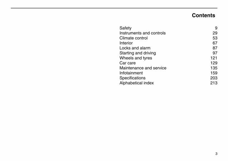
Contents
Safety 9Instruments and controls 29Climate control 53Interior 67Locks and alarm 87Starting and driving 97Wheels and tyres 121Car care 129Maintenance and service 135Infotainment 159Specifications 203Alphabetical index 213
4
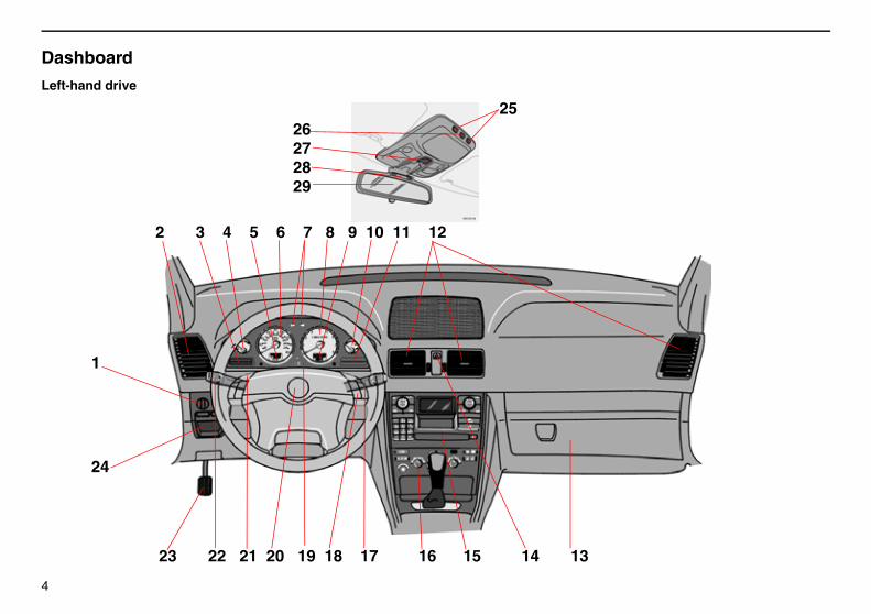
Dashboard
Left-hand drive
2 3 4 5 6 7 8 9 10 11 12
1
24
23 22 21 20 19 18 17 16 15 14 13
26272829
25
5
����1. Lighting panel 382. Air vent 553. Display 354. Temperature gauge 305. Odometer/Trip odometer/
Cruise control 306. Speedometer 307. Direction indicators 308. Tachometer 309. Outside temperature/Clock/
Gear position 3010. Fuel gauge 3011. Indicator and warning
symbols 3112. Air vents 5513. Glovebox 7714. Hazard warning flashers 4215. Audio system 16516. Climate control 56, 6017. Windscreen wipers 4018. Telephone/Audio keypad 16219. Combined instrument panel 3020. Horn 421. Cruise control 4422. Direction indicators/Beam
selection/Read button 39, 3523. Parking brake 45
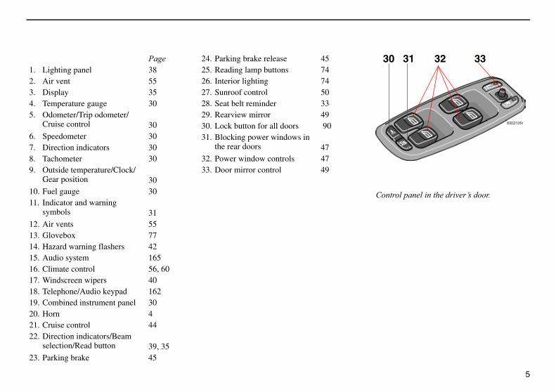
24. Parking brake release 4525. Reading lamp buttons 7426. Interior lighting 7427. Sunroof control 5028. Seat belt reminder 3329. Rearview mirror 4930. Lock button for all doors 9031. Blocking power windows in
the rear doors 4732. Power window controls 4733. Door mirror control 49
30 31 32 33
����������� ������� ���������
6
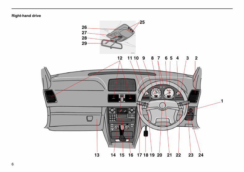
Right-hand drive
1
13 14 15 16 17 18 19 20 21 22 23 24
26272829
25
12 11 10 9 8 7 6 5 4 3 2
7
����1. Lighting panel 382. Air vent 553. Indicator and warning
symbols 314. Fuel gauge 305. Outside temperature/Clock/
Gear position 306. Tachometer 307. Direction indicators 308. Speedometer 309. Odometer/Trip odometer/
Cruise control 3010. Temperature gauge 3011. Display 35 12. Air vents 5513. Glovebox 7714. Hazard warning flashers 4215. Audio system 16516. Climate control 56, 6017. Direction indicators/Beam
selection/Read button 39, 3518. Parking brake 4519. Cruise control 4420. Horn 621. Combined instrument panel 3022. Telephone/Audio keypad 162
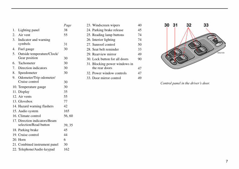
23. Windscreen wipers 4024. Parking brake release 4525. Reading lamp buttons 7426. Interior lighting 7427. Sunroof control 5028. Seat belt reminder 3329. Rearview mirror 4930. Lock button for all doors 9031. Blocking power windows in
the rear doors 4732. Power window controls 4733. Door mirror control 49
����������� ������� ���������
30 31 32 33

8
9
Safety
Seat belts 10
Airbags (SRS) 12
Side airbags (SIPS bag) 15
Roll-Over Protection System (ROPS) 17
Inflatable Curtain (IC) 18
WHIPS 19
When are the safety systems activated? 21
Inspection of airbags, inflatable curtains and seat belt tensioners 22
Child safety 23
10
Safety
Seat belts
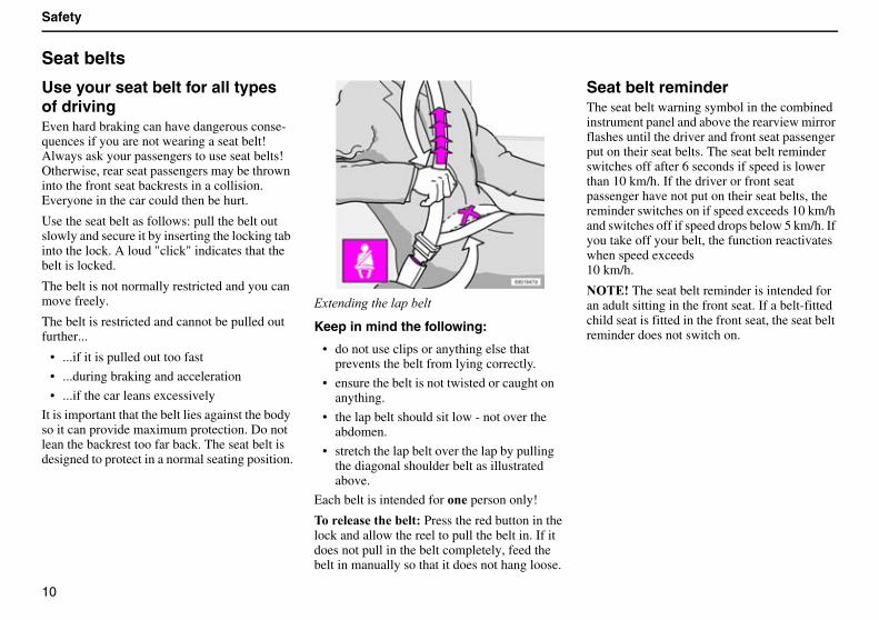
Use your seat belt for all types of drivingEven hard braking can have dangerous conse-quences if you are not wearing a seat belt! Always ask your passengers to use seat belts! Otherwise, rear seat passengers may be thrown into the front seat backrests in a collision. Everyone in the car could then be hurt.
Use the seat belt as follows: pull the belt out slowly and secure it by inserting the locking tab into the lock. A loud "click" indicates that the belt is locked.
The belt is not normally restricted and you can move freely.
The belt is restricted and cannot be pulled out further...
• ...if it is pulled out too fast
• ...during braking and acceleration
• ...if the car leans excessively
It is important that the belt lies against the body so it can provide maximum protection. Do not lean the backrest too far back. The seat belt is designed to protect in a normal seating position.
������ �������������
Keep in mind the following:
• do not use clips or anything else that prevents the belt from lying correctly.
• ensure the belt is not twisted or caught on anything.
• the lap belt should sit low - not over the abdomen.
• stretch the lap belt over the lap by pulling the diagonal shoulder belt as illustrated above.
Each belt is intended for �� person only!
����� �������� Press the red button in the lock and allow the reel to pull the belt in. If it does not pull in the belt completely, feed the belt in manually so that it does not hang loose.
Seat belt reminderThe seat belt warning symbol in the combined instrument panel and above the rearview mirror flashes until the driver and front seat passenger put on their seat belts. The seat belt reminder switches off after 6 seconds if speed is lower than 10 km/h. If the driver or front seat passenger have not put on their seat belts, the reminder switches on if speed exceeds 10 km/h and switches off if speed drops below 5 km/h. If you take off your belt, the function reactivates when speed exceeds10 km/h.
������The seat belt reminder is intended for an adult sitting in the front seat. If a belt-fitted child seat is fitted in the front seat, the seat belt reminder does not switch on.
11
Safety
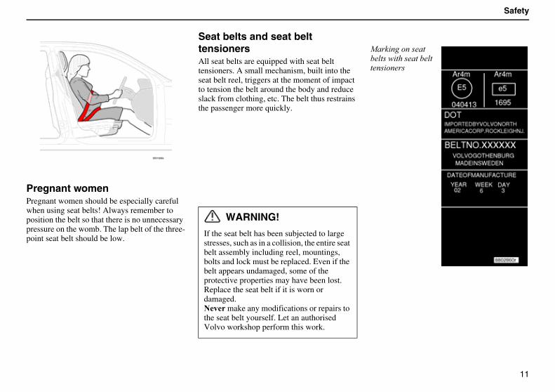
Pregnant womenPregnant women should be especially careful when using seat belts! Always remember to position the belt so that there is no unnecessary pressure on the womb. The lap belt of the three-point seat belt should be low.
Seat belts and seat belt tensionersAll seat belts are equipped with seat belt tensioners. A small mechanism, built into the seat belt reel, triggers at the moment of impact to tension the belt around the body and reduce slack from clothing, etc. The belt thus restrains the passenger more quickly.
��� ����������������� ���������������� ����
WARNING!
If the seat belt has been subjected to large stresses, such as in a collision, the entire seat belt assembly including reel, mountings, bolts and lock must be replaced. Even if the belt appears undamaged, some of the protective properties may have been lost. Replace the seat belt if it is worn or damaged.�� make any modifications or repairs to the seat belt yourself. Let an authorised Volvo workshop perform this work.
12
Safety
Airbags (SRS)
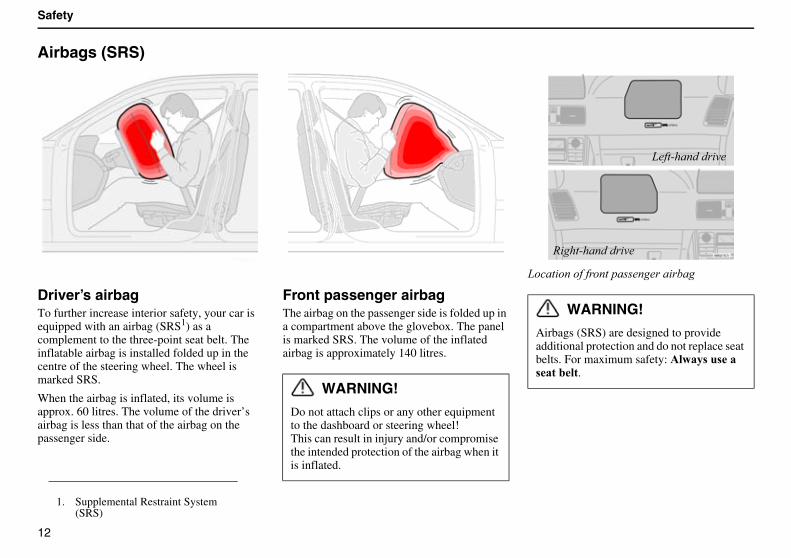
Driver’s airbagTo further increase interior safety, your car is equipped with an airbag (SRS1) as a complement to the three-point seat belt. The inflatable airbag is installed folded up in the centre of the steering wheel. The wheel is marked SRS.
When the airbag is inflated, its volume is approx. 60 litres. The volume of the driver’s airbag is less than that of the airbag on the passenger side.
Front passenger airbag The airbag on the passenger side is folded up in a compartment above the glovebox. The panel is marked SRS. The volume of the inflated airbag is approximately 140 litres.
����� ��������������������� ���
1. Supplemental Restraint System (SRS)
WARNING!
Do not attach clips or any other equipment to the dashboard or steering wheel!This can result in injury and/or compromise the intended protection of the airbag when it is inflated.
WARNING!
Airbags (SRS) are designed to provide additional protection and do not replace seat belts. For maximum safety:������ �� ��� ������.
����������� ��
� ���������� ��
13
Safety
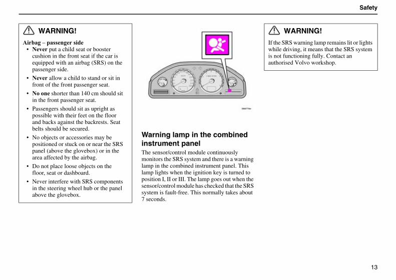
Warning lamp in the combined instrument panelThe sensor/control module continuously monitors the SRS system and there is a warning lamp in the combined instrument panel. This lamp lights when the ignition key is turned to position I, II or III. The lamp goes out when the sensor/control module has checked that the SRS system is fault-free. This normally takes about 7 seconds.
WARNING!
���������� ��� ��• �� put a child seat or booster
cushion in the front seat if the car is equipped with an airbag (SRS) on the passenger side.
• �� allow a child to stand or sit in front of the front passenger seat.
• ����� shorter than 140 cm should sit in the front passenger seat.
• Passengers should sit as upright as possible with their feet on the floor and backs against the backrests. Seat belts should be secured.
• No objects or accessories may be positioned or stuck on or near the SRS panel (above the glovebox) or in the area affected by the airbag.
• Do not place loose objects on the floor, seat or dashboard.
• Never interfere with SRS components in the steering wheel hub or the panel above the glovebox.
WARNING!
If the SRS warning lamp remains lit or lights while driving, it means that the SRS system is not functioning fully. Contact an authorised Volvo workshop.
14
Safety
Airbags (SRS) (Contd)
����� ���!"����������� ��
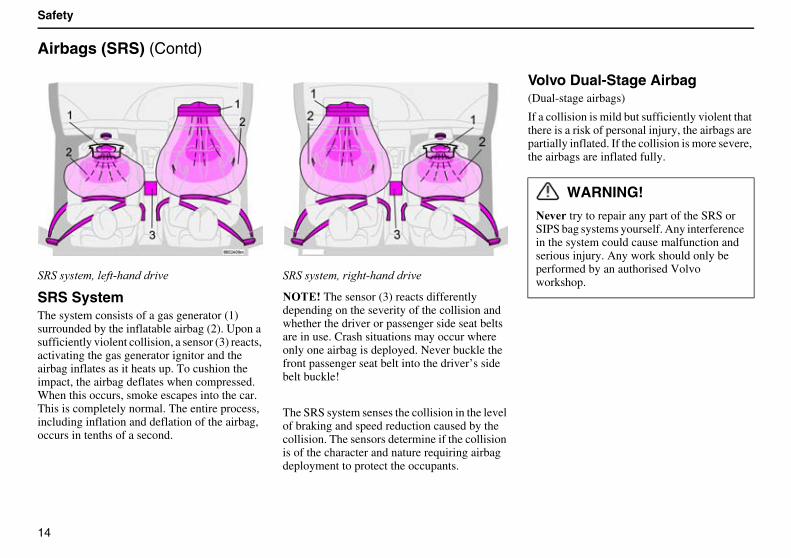
SRS SystemThe system consists of a gas generator (1) surrounded by the inflatable airbag (2). Upon a sufficiently violent collision, a sensor (3) reacts, activating the gas generator ignitor and the airbag inflates as it heats up. To cushion the impact, the airbag deflates when compressed. When this occurs, smoke escapes into the car. This is completely normal. The entire process, including inflation and deflation of the airbag, occurs in tenths of a second.
����� ���!"� ���������� ��
������The sensor (3) reacts differently depending on the severity of the collision and whether the driver or passenger side seat belts are in use. Crash situations may occur where only one airbag is deployed. Never buckle the front passenger seat belt into the driver’s side belt buckle!
The SRS system senses the collision in the level of braking and speed reduction caused by the collision. The sensors determine if the collision is of the character and nature requiring airbag deployment to protect the occupants.
Volvo Dual-Stage Airbag(Dual-stage airbags)
If a collision is mild but sufficiently violent that there is a risk of personal injury, the airbags are partially inflated. If the collision is more severe, the airbags are inflated fully.
WARNING!
�� try to repair any part of the SRS or SIPS bag systems yourself. Any interference in the system could cause malfunction and serious injury. Any work should only be performed by an authorised Volvo workshop.
15
Safety
Side airbags (SIPS bag)
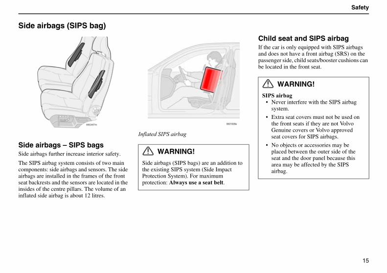
Side airbags – SIPS bagsSide airbags further increase interior safety.
The SIPS airbag system consists of two main components: side airbags and sensors. The side airbags are installed in the frames of the front seat backrests and the sensors are located in the insides of the centre pillars. The volume of an inflated side airbag is about 12 litres.
#��������#���� ���
Child seat and SIPS airbagIf the car is only equipped with SIPS airbags and does not have a front airbag (SRS) on the passenger side, child seats/booster cushions can be located in the front seat.
WARNING!
Side airbags (SIPS bags) are an addition to the existing SIPS system (Side Impact Protection System). For maximum protection:������ �� ��� ������.
WARNING!
����������• Never interfere with the SIPS airbag
system.
• Extra seat covers must not be used on the front seats if they are not Volvo Genuine covers or Volvo approved seat covers for SIPS airbags.
• No objects or accessories may be placed between the outer side of the seat and the door panel because this area may be affected by the SIPS airbag.
16
Safety
Side airbags (SIPS bag) (Contd)
����������� ��
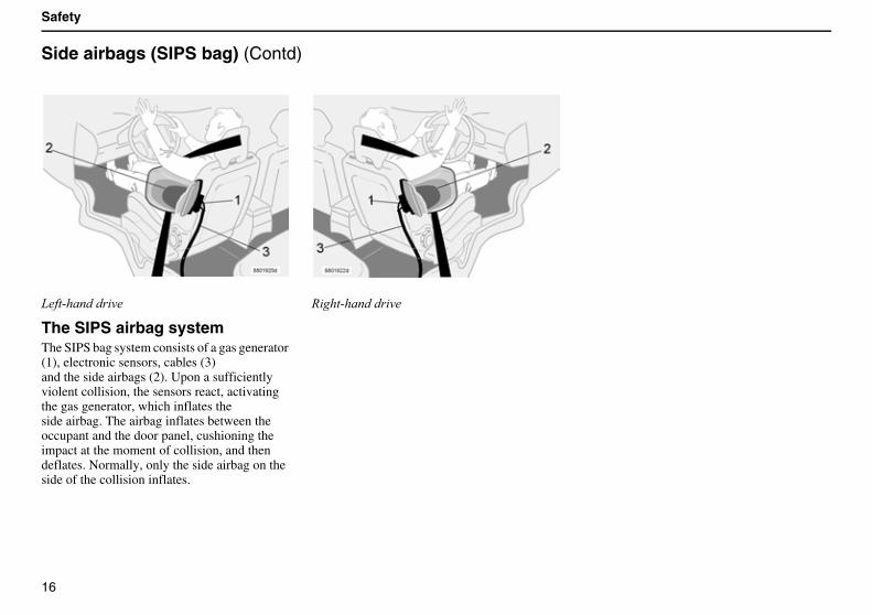
The SIPS airbag systemThe SIPS bag system consists of a gas generator (1), electronic sensors, cables (3)and the side airbags (2). Upon a sufficiently violent collision, the sensors react, activating the gas generator, which inflates theside airbag. The airbag inflates between the occupant and the door panel, cushioning the impact at the moment of collision, and then deflates. Normally, only the side airbag on the side of the collision inflates.
� ���������� ��
17
Safety
Roll-Over Protection System (ROPS)
Volvo’s Roll-Over Protection System has been designed to reduce the risk of the car overturning and to provide the best possible protection in the event of an accident.
The system consists of:
• A stabiliser system, RSC (Roll Stability Control) that minimises the risk of overturning during sudden evasive manoeuvres or the like or if the car skids.
• Increased protection for the driver and passengers through a reinforced body, inflatable curtains and seat belt tensioners in all seats. See page 11 and page 18.
The RSC system uses a gyro sensor which registers changes in the car’s lateral inclination angle. This information is then used to calculate the risk for overturning. If a risk is detected, the DSTC system is engaged, engine speed is reduced and one or more wheels are braked until the car returns to a stable position.
For more information on the DSTC system, see page 34 and page 108.
WARNING!
Under normal driving conditions, the RSC system improves the car’s road safety, but this should not be taken as a reason to increase speed. Always follow the usual precautions for safe driving.
18
Safety
Inflatable Curtain (IC)
Inflatable Curtain (IC)(Inflatable Curtain)
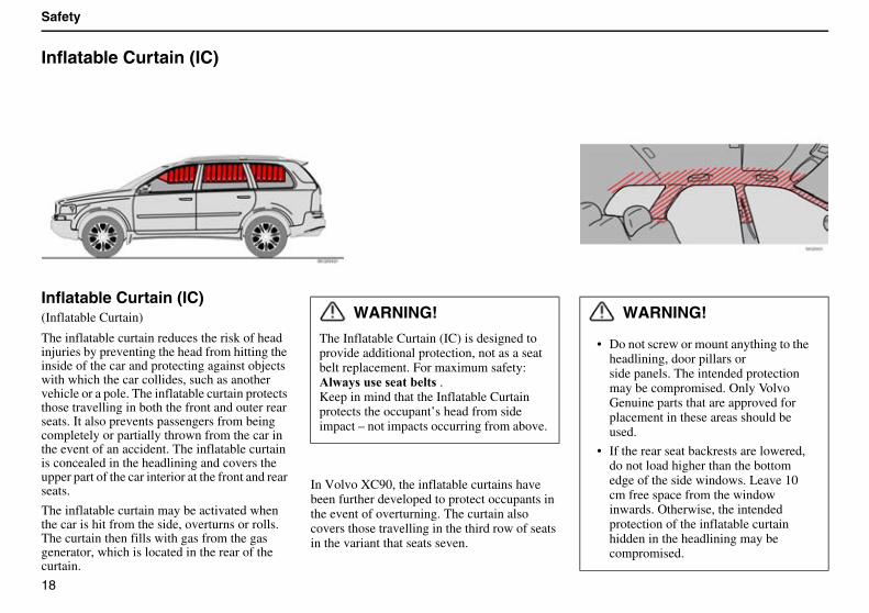
The inflatable curtain reduces the risk of head injuries by preventing the head from hitting the inside of the car and protecting against objects with which the car collides, such as another vehicle or a pole. The inflatable curtain protects those travelling in both the front and outer rear seats. It also prevents passengers from being completely or partially thrown from the car in the event of an accident. The inflatable curtain is concealed in the headlining and covers the upper part of the car interior at the front and rear seats.
The inflatable curtain may be activated when the car is hit from the side, overturns or rolls. The curtain then fills with gas from the gas generator, which is located in the rear of the curtain.
In Volvo XC90, the inflatable curtains have been further developed to protect occupants in the event of overturning. The curtain also covers those travelling in the third row of seats in the variant that seats seven.
WARNING!
The Inflatable Curtain (IC) is designed to provide additional protection, not as a seat belt replacement. For maximum safety:������ �� � ������ �.Keep in mind that the Inflatable Curtain protects the occupant’s head from side impact – not impacts occurring from above.
WARNING!
• Do not screw or mount anything to the headlining, door pillars orside panels. The intended protection may be compromised. Only Volvo Genuine parts that are approved for placement in these areas should be used.
• If the rear seat backrests are lowered, do not load higher than the bottom edge of the side windows. Leave 10 cm free space from the window inwards. Otherwise, the intended protection of the inflatable curtain hidden in the headlining may be compromised.
19
Safety
WHIPS
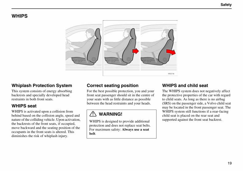
Whiplash Protection SystemThis system consists of energy absorbing backrests and specially developed head restraints in both front seats.
WHIPS seatWHIPS is activated upon a collision from behind based on the collision angle, speed and nature of the colliding vehicle. Upon activation, the backrests of the front seats, if occupied, move backward and the seating position of the occupants in the front seats is altered. This diminishes the risk of whiplash injury.
Correct seating positionFor the best possible protection, you and your front seat passenger should sit in the centre of your seats with as little distance as possible between the head restraints and your heads.
WHIPS and child seatThe WHIPS system does not negatively affect the protective properties of the car with regard to child seats. As long as there is no airbag (SRS) on the passenger side, a Volvo child seat may be located in the front passenger seat. The WHIPS system still functions if a rear-facing child seat is placed on the rear seat and supported against the front seat backrest.
WARNING!
WHIPS is designed to provide additional protection and does not replace seat belts.For maximum safety:������ �� ��� ������.
20
Safety
WHIPS (Contd)
WARNING!
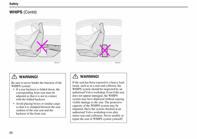
Be sure to never hinder the function of the WHIPS system!
• If a rear backrest is folded down, the corresponding front seat must be adjusted so that it is not in contact with the folded backrest.
• Avoid placing boxes or similar cargo so that it is clamped between the seat cushion of the rear seat and the backrest of the front seat.
WARNING!
If the seat has been exposed to a heavy load strain, such as in a rear-end collision, the WHIPS system should be inspected by an authorised Volvo workshop. Even if the seat does not appear damaged, the WHIPS system may have deployed without causing visible damage to the seat. The protective capacity of the WHIPS system may be impaired. Have the system checked at an authorised Volvo workshop even after minor rear-end collisions. Never modify or repair the seat or WHIPS system yourself!
21
Safety
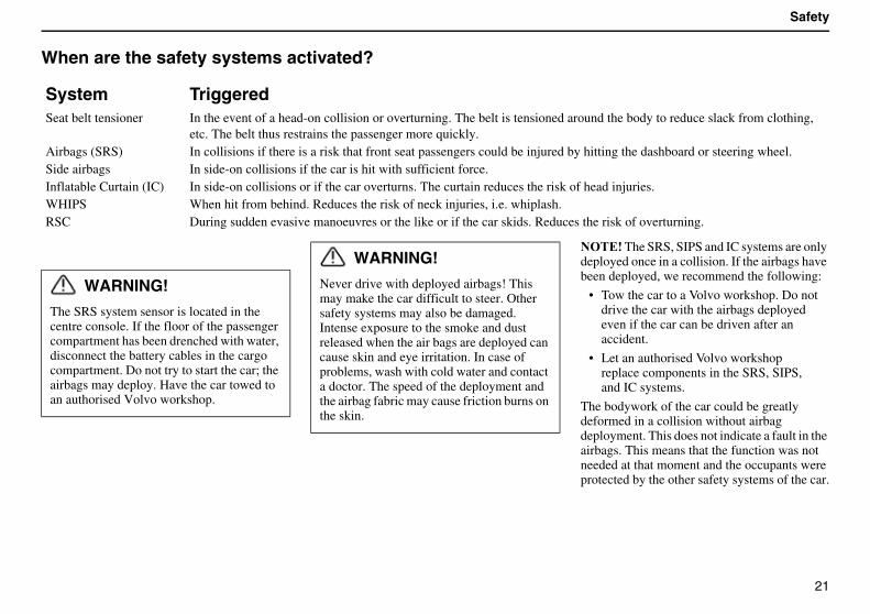
When are the safety systems activated?
������The SRS, SIPS and IC systems are only deployed once in a collision. If the airbags have been deployed, we recommend the following:
• Tow the car to a Volvo workshop. Do not drive the car with the airbags deployed even if the car can be driven after an accident.
• Let an authorised Volvo workshop replace components in the SRS, SIPS, and IC systems.
The bodywork of the car could be greatly deformed in a collision without airbag deployment. This does not indicate a fault in the airbags. This means that the function was not needed at that moment and the occupants were protected by the other safety systems of the car.
System TriggeredSeat belt tensioner In the event of a head-on collision or overturning. The belt is tensioned around the body to reduce slack from clothing,
etc. The belt thus restrains the passenger more quickly.Airbags (SRS) In collisions if there is a risk that front seat passengers could be injured by hitting the dashboard or steering wheel.Side airbags In side-on collisions if the car is hit with sufficient force.Inflatable Curtain (IC) In side-on collisions or if the car overturns. The curtain reduces the risk of head injuries.WHIPS When hit from behind. Reduces the risk of neck injuries, i.e. whiplash.RSC During sudden evasive manoeuvres or the like or if the car skids. Reduces the risk of overturning.
WARNING!
The SRS system sensor is located in the centre console. If the floor of the passenger compartment has been drenched with water, disconnect the battery cables in the cargo compartment. Do not try to start the car; the airbags may deploy. Have the car towed to an authorised Volvo workshop.
WARNING!
Never drive with deployed airbags! This may make the car difficult to steer. Other safety systems may also be damaged. Intense exposure to the smoke and dust released when the air bags are deployed can cause skin and eye irritation. In case of problems, wash with cold water and contact a doctor. The speed of the deployment and the airbag fabric may cause friction burns on the skin.
22
Safety
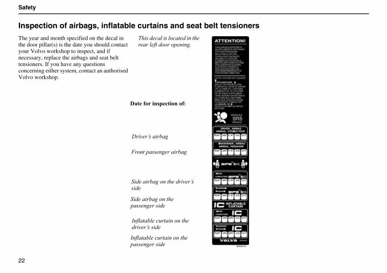
Inspection of airbags, inflatable curtains and seat belt tensioners
The year and month specified on the decal in the door pillar(s) is the date you should contact your Volvo workshop to inspect, and if necessary, replace the airbags and seat belt tensioners. If you have any questions concerning either system, contact an authorised Volvo workshop.
$� ������� ��������� ��������������������� ���
% ������ ���
&�������������� ����
� ���� ������������ ������ ��
� ���� ��������������������� ��
#���������'�� ���������� ������ ��
#���������'�� ������������������� ��
���� ���� �!������ �
23
Safety
Child safety
Children should sit comfortably and safelyRemember that children, regardless of age or size, should always be securely strapped into the car. Never allow a child to sit on the knee of a passenger!
The weight and height of the child must be taken into consideration when selecting equipment and its location. See page 24.
Volvo’s own child safety equipment is designed for your car. If you select Volvo equipment, you can be sure that the mounting points and attach-ments are correctly positioned and sufficiently strong.
Children up to 3 years of age sit safest in a rear-facing child seat.
������Many countries have regulations regarding where children should be located in the car. Find out what laws apply in the countries you will be visiting.
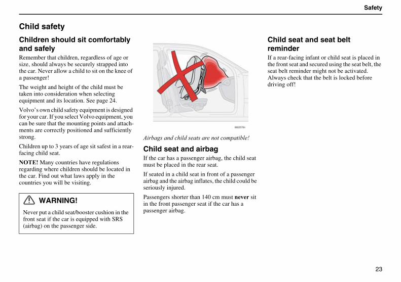
( ����������� �����������������!��� ��)
Child seat and airbagIf the car has a passenger airbag, the child seat must be placed in the rear seat.
If seated in a child seat in front of a passenger airbag and the airbag inflates, the child could be seriously injured.
Passengers shorter than 140 cm must �� sit in the front passenger seat if the car has a passenger airbag.
Child seat and seat belt reminderIf a rear-facing infant or child seat is placed in the front seat and secured using the seat belt, the seat belt reminder might not be activated. Always check that the belt is locked before driving off!
WARNING!
Never put a child seat/booster cushion in the front seat if the car is equipped with SRS (airbag) on the passenger side.
24
Safety
Child safety (Contd)
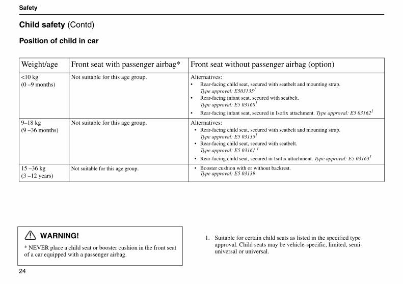
Position of child in car
Weight/age Front seat with passenger airbag* Front seat without passenger airbag (option)
<10 kg(0 –9 months)
Not suitable for this age group. Alternatives:• Rear-facing child seat, secured with seatbelt and mounting strap.
$ ���������*��+,-.-+.
• Rear-facing infant seat, secured with seatbelt.$ ���������*��+�,-./,.
• Rear-facing infant seat, secured in Isofix attachment. $ ���������*��+�,-./0.
9–18 kg(9 –36 months)
Not suitable for this age group. Alternatives:• Rear-facing child seat, secured with seatbelt and mounting strap.
$ ���������*��+�,-.-+.
• Rear-facing child seat, secured with seatbelt.$ ���������*��+�,-./.�.�
• Rear-facing child seat, secured in Isofix attachment. $ ���������*��+�,-./-.
15 –36 kg(3 –12 years)
Not suitable for this age group. • Booster cushion with or without backrest.$ ���������*��+�,-.-1
WARNING!
* NEVER place a child seat or booster cushion in the front seat of a car equipped with a passenger airbag.
1. Suitable for certain child seats as listed in the specified type approval. Child seats may be vehicle-specific, limited, semi-universal or universal.
25
Safety
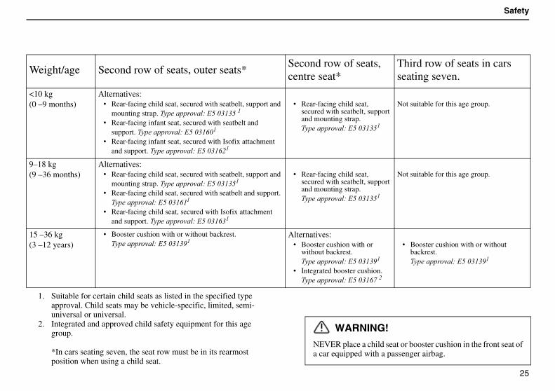
Weight/age Second row of seats, outer seats*Second row of seats, centre seat*
Third row of seats in cars seating seven.
<10 kg(0 –9 months)
Alternatives:• Rear-facing child seat, secured with seatbelt, support and
mounting strap.�$ ���������*��+�,-.-+�.
• Rear-facing infant seat, secured with seatbelt and support. $ ���������*��+�,-./,.
• Rear-facing infant seat, secured with Isofix attachment and support. $ ���������*��+�,-./0.
• Rear-facing child seat, secured with seatbelt, support and mounting strap.$ ���������*��+�,-.-+.
Not suitable for this age group.
9–18 kg(9 –36 months)
Alternatives:• Rear-facing child seat, secured with seatbelt, support and
mounting strap.�$ ���������*��+�,-.-+.
• Rear-facing child seat, secured with seatbelt and support. $ ���������*��+�,-./..
• Rear-facing child seat, secured with Isofix attachment and support. $ ���������*��+�,-./-.
• Rear-facing child seat, secured with seatbelt, support and mounting strap.$ ���������*��+�,-.-+.
Not suitable for this age group.
15 –36 kg(3 –12 years)
• Booster cushion with or without backrest.$ ���������*��+�,-.-1.
Alternatives:• Booster cushion with or
without backrest.$ ���������*��+�,-.-1.
• Integrated booster cushion.$ ���������*��+�,-./2�0�
• Booster cushion with or without backrest.$ ���������*��+�,-.-1.
1. Suitable for certain child seats as listed in the specified type approval. Child seats may be vehicle-specific, limited, semi-universal or universal.
2. Integrated and approved child safety equipment for this age group.
*In cars seating seven, the seat row must be in its rearmost position when using a child seat.
WARNING!
NEVER place a child seat or booster cushion in the front seat of a car equipped with a passenger airbag.
26
Safety
Child safety (Contd)
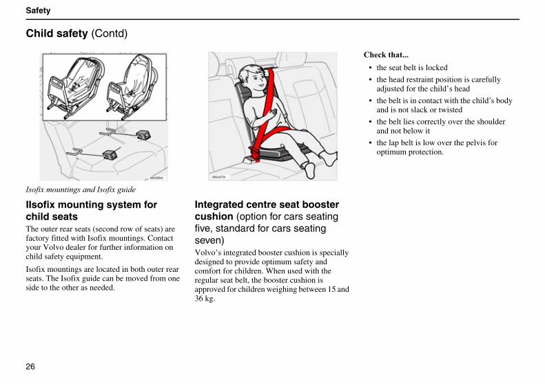
#��� ��!�'�� ��������#��� ���' ��
IIsofix mounting system for child seatsThe outer rear seats (second row of seats) are factory fitted with Isofix mountings. Contact your Volvo dealer for further information on child safety equipment.
Isofix mountings are located in both outer rear seats. The Isofix guide can be moved from one side to the other as needed.
Integrated centre seat booster cushion (option for cars seating five, standard for cars seating seven)Volvo’s integrated booster cushion is specially designed to provide optimum safety and comfort for children. When used with the regular seat belt, the booster cushion is approved for children weighing between 15 and 36 kg.
"�!#�����$$$
• the seat belt is locked
• the head restraint position is carefully adjusted for the child’s head
• the belt is in contact with the child’s body and is not slack or twisted
• the belt lies correctly over the shoulder and not below it
• the lap belt is low over the pelvis for optimum protection.
27
Safety
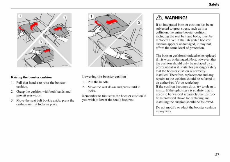
%�� ���������� ��!� ����
1. Pull that handle to raise the booster cushion.
2. Grasp the cushion with both hands and moveit rearwards.
3. Move the seat belt buckle aside; press the cushion until it locks in place.
&������������ ��!� ����
1. Pull the handle.
2. Move the seat down and press until it locks.
Remember to first stow the booster cushion if you wish to lower the seat’s backrest.
WARNING!
If an integrated booster cushion has been subjected to great stress, such as in a collision, the entire booster cushion, including the seat belt and bolts, must be replaced. Even if the integrated booster cushion appears undamaged, it may not afford the same level of protection.
The booster cushion should also be replaced if it is worn or damaged. Note, however, that the cushion should only be replaced by a professional as it is vital for passenger safety that the booster cushion is correctly installed. Therefore, replacement and any repairs to the cushion should be referred to an authorised Volvo workshop.If the cushion becomes dirty, try to clean it in situ. If the upholstery is so dirty that it needs to be washed separately, the instruc-tions provided above for replacing and installing the cushion should be followed.
Do not modify or adapt the booster cushion in any way.
28
Safety
Child safety (Contd)
Important tips!When using other child safety products that are available on the market, it is �'������ to read the installation instructions that accompany the product and follow them carefully. Here are some points you should consider:
• Volvo has child safety products that are designed for and tested by Volvo.
• The child seat must always be placed according to the manufacturer’s direc-tions. See the child seat instruction manual for further installation instruc-tions.
• Do not attach the child seat straps to the horizontal adjustment bar, springs or any of the rails and struts under the seat that may have sharp edges.
• Allow the backrest of the child seat to rest against the dashboard (Applies to cars�������� an airbag (SRS) on the passenger side).
• Never place a child seat in the front seat if the car is equipped with an airbag (SRS) on the passenger side.
������If there are any problems with instal-lation of child safety products, contact the manufacturer for clearer installation instruc-tions.
WARNING!
Support cushions/child seats with steel frames or another design that can lie against the seatbelt release button must not be used because they can cause accidental release of the seat-belt. Do not allow the top of the child seat to rest against the windscreen.
29
Instruments and controls
Combined instrument panel 30
Indicator and warning symbols 31
Switches in the centre console 36
Lighting panel 38
Direction indicator lever 39
Windscreen wipers/washer 40
Hazard warning flashers, rear window and door mirror defrosters, heated front seats 42
Trip computer 43
Cruise control 44
Parking brake, bonnet, electric socket, etc. 45
Power windows 47
Rearview mirror/door mirrors 49
Power sunroof (option) 50
30
Instruments and controls
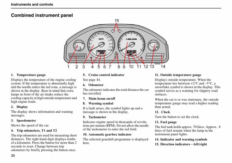
Combined instrument panel
($ �'���������Displays the temperature of the engine cooling system. If the temperature is abnormally high and the needle enters the red zone, a message is shown in the display. Bear in mind that extra lamps in front of the air intake reduce the cooling capacity at high outside temperature and high engine loads.
)$ �� ����The display shows information and warning messages.
*$ ����'�Shows the speed of the car.
+$ �������'� ,��(������)The trip odometers are used for measuring short distances. The right-hand digit displays tenths of a kilometre. Press the button for more than 2 seconds to reset. Change between trip odometers by briefly pressing the button once.
-$ "�� �!����������!���See page 44.
.$ ���'�The odometer indicates the total distance the car has travelled.
/$ 0������'���1� 2$ 3������ �'���If a fault arises, the symbol lights up and a message is shown in the display.
4$ ��!��'�Indicates engine speed in thousands of revolu-tions per minute (RPM). Do not allow the needle of the tachometer to enter the red field.
(5$ ����'���!�����6�����!���The selected gearshift programme is displayed here.
(($ ��� ����'���������Displays outside temperature. When the temperature lies between +2°C and –5°C, a snowflake symbol is shown in the display. This symbol serves as a warning for slippery road surfaces.
When the car is or was stationary, the outside temperature gauge may read a higher reading than actual.
()$ �"��!#Turn the button to set the clock.
(*$ 7�������The fuel tank holds approx. 70 litres. Approx. 8 litres of fuel remain when the lamp in the instrument panel lights.
(+$ ����!��������������� �'��� (-$ ��!���������!��� ���� �1����
31
Instruments and controls
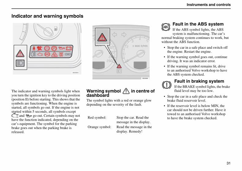
Indicator and warning symbols
The indicator and warning symbols light when you turn the ignition key to the driving position (position II) before starting. This shows that the symbols are functioning. When the engine is started, all symbols go out. If the engine is not started within 5 seconds, all symbols except
and go out. Certain symbols may not have the function indicated, depending on the car’s equipment. The symbol for the parking brake goes out when the parking brake is released.
Warning symbol in centre of dashboardThe symbol lights with a red or orange glow depending on the severity of the fault.
Fault in the ABS systemIf the ABS symbol lights, the ABS system is malfunctioning. The car’s
normal braking system continues to work, but without the ABS function.
• Stop the car in a safe place and switch off the engine. Restart the engine.
• If the warning symbol goes out, continue driving. It was an indicator error.
• If the warning symbol remains lit, drive to an authorised Volvo workshop to have the ABS system checked.
Fault in braking systemIf the BRAKE symbol lights, the brake fluid level may be too low.
• Stop the car in a safe place and check the brake fluid reservoir level.
• If the reservoir level is below MIN, the car should not be driven further. Have it towed to an authorised Volvo workshop to have the brake system checked.Red symbol: Stop the car. Read the
message in the display.Orange symbol: Read the message in the
display. Remedy!
32
Instruments and controls
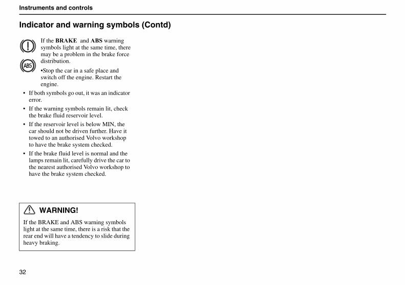
Indicator and warning symbols (Contd)
If the 8%�9�� and �8� warning symbols light at the same time, there may be a problem in the brake force distribution.
•Stop the car in a safe place and switch off the engine. Restart the engine.
• If both symbols go out, it was an indicator error.
• If the warning symbols remain lit, check the brake fluid reservoir level.
• If the reservoir level is below MIN, the car should not be driven further. Have it towed to an authorised Volvo workshop to have the brake system checked.
• If the brake fluid level is normal and the lamps remain lit, carefully drive the car to the nearest authorised Volvo workshop to have the brake system checked.
WARNING!
If the BRAKE and ABS warning symbols light at the same time, there is a risk that the rear end will have a tendency to slide during heavy braking.
33
Instruments and controls
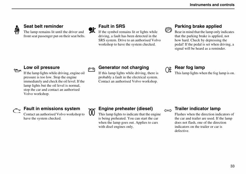
Seat belt reminderThe lamp remains lit until the driver and front seat passenger put on their seat belts.
Fault in SRSIf the symbol remains lit or lights while driving, a fault has been detected in the SRS system. Drive to an authorised Volvo workshop to have the system checked.
Parking brake appliedBear in mind that the lamp only indicates that the parking brake is applied, not how hard. Check by depressing the pedal! If the pedal is set when driving, a signal will be heard as a reminder.
Low oil pressureIf the lamp lights while driving, engine oil pressure is too low. Stop the engine immediately and check the oil level. If the lamp lights but the oil level is normal, stop the car and contact an authorised Volvo workshop.
Generator not chargingIf this lamp lights while driving, there is probably a fault in the electrical system. Contact an authorised Volvo workshop.
Rear fog lampThis lamp lights when the fog lamp is on.
Fault in emissions systemContact an authorised Volvo workshop to have the system checked.
Engine preheater (diesel)This lamp lights to indicate that the engine is being preheated. You can start the car when the lamp goes out. Applies to cars with disel engines only.
Trailer indicator lampFlashes when the direction indicators of the car and trailer are used. If the lamp does not flash, one of the direction indicators on the trailer or car is defective.
34
Instruments and controls
Indicator and warning symbols (Contd)
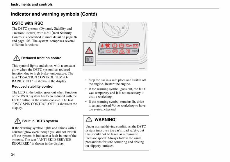
DSTC with RSC The DSTC system (Dynamic Stability and Traction Control) with RSC (Roll Stability Control) is described in more detail on page 36 and page 108. The system comprises several different functions:
Reduced traction control
This symbol lights and shines with a constant glow when the DSTC system has reduced function due to high brake temperature. The text "TRACTION CONTROL TEMPO-RARILY OFF" is shown in the display.
Reduced stability control
The LED in the button goes out when function of the DSTC system has been reduced with the DSTC button in the centre console. The text "DSTC SPIN CONTROL OFF" is shown in the display.
Fault in DSTC system
If the warning symbol lights and shines with a constant glow even though you did not switch off the system, it indicates a fault in one of the systems. The text "ANTI-SKID SERVICE REQUIRED" is shown in the display.
• Stop the car in a safe place and switch off the engine. Restart the engine.
• If the warning symbol goes out, the fault was temporary and it is not necessary to visit a workshop.
• If the warning symbol remains lit, drive to an authorised Volvo workshop to have the system checked.
WARNING!
Under normal driving conditions, the DSTC system improves the car’s road safety, but this should not be taken as a reason to increase speed. Always follow the usual precautions for safe cornering and driving on slippery surfaces.
35
Instruments and controls
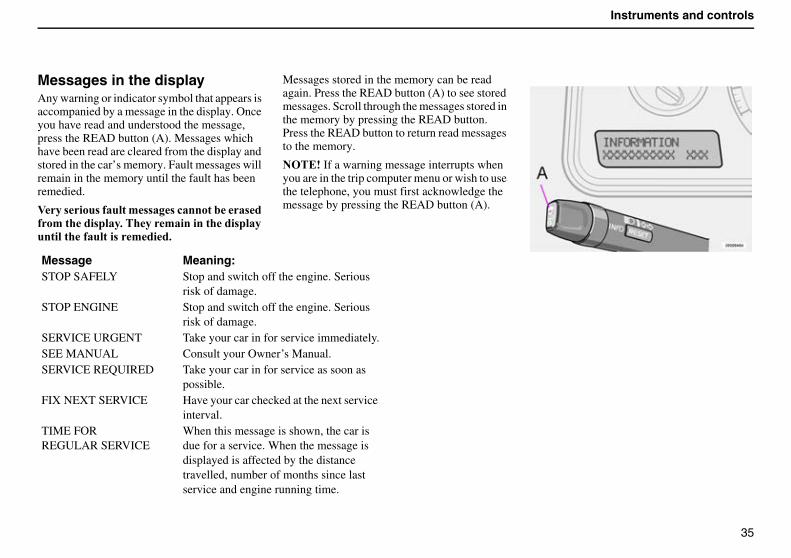
Messages in the displayAny warning or indicator symbol that appears is accompanied by a message in the display. Once you have read and understood the message, press the READ button (A). Messages which have been read are cleared from the display and stored in the car’s memory. Fault messages will remain in the memory until the fault has been remedied.
:�� ��� � �����' �� �!��������� �� �'������ ����$�����'������������ �������������� ������ �'���$
Messages stored in the memory can be read again. Press the READ button (A) to see stored messages. Scroll through the messages stored in the memory by pressing the READ button. Press the READ button to return read messages to the memory.
������If a warning message interrupts when you are in the trip computer menu or wish to use the telephone, you must first acknowledge the message by pressing the READ button (A).
Message Meaning:STOP SAFELY Stop and switch off the engine. Serious
risk of damage.STOP ENGINE Stop and switch off the engine. Serious
risk of damage.SERVICE URGENT Take your car in for service immediately.SEE MANUAL Consult your Owner’s Manual.SERVICE REQUIRED Take your car in for service as soon as
possible.FIX NEXT SERVICE Have your car checked at the next service
interval.TIME FORREGULAR SERVICE
When this message is shown, the car is due for a service. When the message is displayed is affected by the distance travelled, number of months since last service and engine running time.
36
Instruments and controls
Switches in the centre console
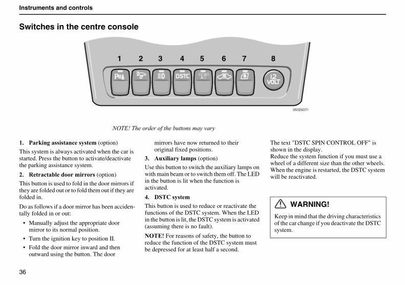
($ ��#����� � ���!� � �' (option)
This system is always activated when the car is started. Press the button to activate/deactivate the parking assistance system.
)$ %��!���������'�� (option)
This button is used to fold in the door mirrors if they are folded out or to fold them out if they are folded in.
Do as follows if a door mirror has been acciden-tally folded in or out:
• Manually adjust the appropriate door mirror to its normal position.
• Turn the ignition key to position II.
• Fold the door mirror inward and then outward using the button. The door
mirrors have now returned to their original fixed positions.
*$ ��6��������'� (option)
Use this button to switch the auxiliary lamps on with main beam or to switch them off. The LED in the button is lit when the function is activated.
+$ ���"� � �'
This button is used to reduce or reactivate the functions of the DSTC system. When the LED in the button is lit, the DSTC system is activated (assuming there is no fault).
������For reasons of safety, the button to reduce the function of the DSTC system must be depressed for at least half a second.
The text "DSTC SPIN CONTROL OFF" is shown in the display.Reduce the system function if you must use a wheel of a different size than the other wheels.When the engine is restarted, the DSTC system will be reactivated.
34$�)�$���������������'������!� ���
1 2 3 4 5 6 7 8
WARNING!
Keep in mind that the driving characteristics of the car change if you deactivate the DSTC system.
37
Instruments and controls
-$ ���!��������������������� ������ ���!�'���'���(option)
Press the button to activate the air conditioning in the rear of the passenger compartment. Rear air conditioning is deactivated when the ignition is completely switched off.
.$ ��!�����������������!#� ��!�����������!��
Use this button if you wish to switch off the deadlock function (deadlock means that the doors cannot be opened from the inside when they are locked). This button is also used to deactivate the movement and tilt detectors in the alarm system. The LED lights when these systems are deactivated.
/$ "����� � �����!# ������������ �(option)
Use this button when you wish to activate or deactivate the electric child safety locks in therear doors. The ignition key must be in position I or II. When the child safety locks are activated, the LED in the button lights. A message is shown in the display when you activate or deactivate the child safety locks.
2$ ��!��!� �!#��(standard)1�"������������(option)
The electric socket can be used for various 12V accessories, such as mobile phones or coolers. The cigarette lighter is activated by pushing in the button . Once the lighter has been heated, the button pops out again. Pull out the lighter
and use the heated coils. For reasons of safety, always keep the cover on the socket when it is not in use. The maximum current is 10A.
38
Instruments and controls
Lighting panel
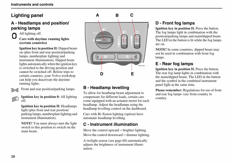
A - Headlamps and position/parking lamps
All lighting off.
"� �����������'������������� �;!�����!����� <
���������#������� ��������� Dipped beam on (plus front and rear position/parking lamps, numberplate lighting and instrument illumination). Dipped beam lights automatically when the ignition key is switched to the driving position and cannot be switched off. Before trips to certain countries, your Volvo workshop can help you deactivate the daytime running lights.
Front and rear position/parking lamps.
���������#������� ������5� All lightingoff.
���������#������� ��������� Headlamps light (plus front and rear position/parking lamps, numberplate lighting and instrument illumination).
������You must always turn the light switch to this position to switch on the main beam.
B - Headlamp levellingTo allow for headlamp beam adjustment to compensate for different loads, certain cars come equipped with an actuator motor for each headlamp. Adjust the headlamps using the headlamp levelling control on the dashboard.
Cars with Bi-Xenon lighting (option) have automatic headlamp levelling.
C - Instrument illuminationMove the control upward � brighter lighting.Move the control downward ��dimmer lighting.
A twilight sensor (see page 60) automatically adjusts the brightness of instrument illumi-nation.
D - Front fog lamps���������#������� ��������$ Press the button. The fog lamps light in combination with the position/parking lamps and main/dipped beam. The LED in the button is lit while the fog lamps are on.
������In some countries, dipped beam may not be used in combination with front fog lamps.
E - Rear fog lamps���������#������� ��������$�Press the button. The rear fog lamp lights in combination with the main/dipped beam. The LED in the button and the symbol in the combined instrument panel light at the same time.
��� �''�� Regulations for use of front and rear fog lamps vary from country to country.
D E
A B C
39
Instruments and controls
Direction indicator lever
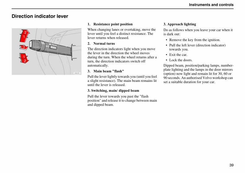
($ % � ���!��������� �����
When changing lanes or overtaking, move the lever until you feel a distinct resistance. The lever returns when released.
)$ ��'������
The direction indicators light when you move the lever in the direction the wheel moves during the turn. When the wheel returns after a turn, the direction indicators switch off automatically.
*$ 0������'�= �� �=
Pull the lever lightly towards you (until you feel a slight resistance). The main beam remains lit until the lever is released.
*$�����!����,�'���1���������'
Pull the lever towards you past the "flash position" and release it to change between main and dipped beam.
*$������!����������
Do as follows when you leave your car when it is dark out:
• Remove the key from the ignition.
• Pull the left lever (direction indicator) towards you.
• Exit the car.
• Lock the doors.
Dipped beam, position/parking lamps, number-plate lighting and the lamps in the door mirrors (option) now light and remain lit for 30, 60 or 90 seconds. An authorised Volvo workshop can set a suitable duration for your car.
40
Instruments and controls
Windscreen wipers/washer
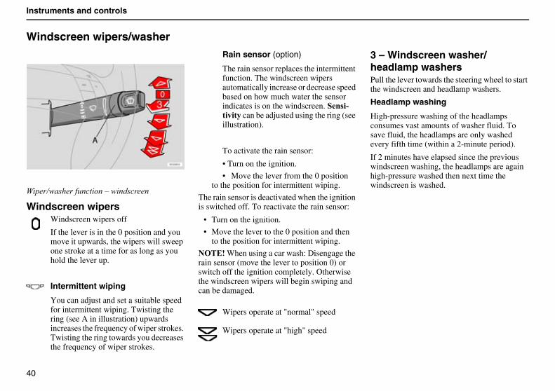
5 ��6�������'��� ���7�� �������
Windscreen wipersWindscreen wipers off
If the lever is in the 0 position and you move it upwards, the wipers will sweep one stroke at a time for as long as you hold the lever up.
Intermittent wiping�
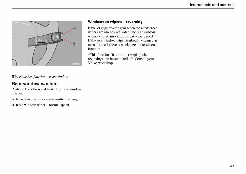
You can adjust and set a suitable speed for intermittent wiping. Twisting the ring (see A in illustration) upwards increases the frequency of wiper strokes. Twisting the ring towards you decreases the frequency of wiper strokes.
Rain sensor (option)
The rain sensor replaces the intermittent function. The windscreen wipers automatically increase or decrease speed based on how much water the sensor indicates is on the windscreen. �� �>������ can be adjusted using the ring (see illustration).
To activate the rain sensor:
• Turn on the ignition.
• Move the lever from the 0 position to the position for intermittent wiping.
The rain sensor is deactivated when the ignition is switched off. To reactivate the rain sensor:
• Turn on the ignition.
• Move the lever to the 0 position and then to the position for intermittent wiping.
������When using a car wash: Disengage the rain sensor (move the lever to position 0) or switch off the ignition completely. Otherwise the windscreen wipers will begin swiping and can be damaged.
Wipers operate at "normal" speed
Wipers operate at "high" speed
3 – Windscreen washer/ headlamp washersPull the lever towards the steering wheel to start the windscreen and headlamp washers.
Headlamp washing
High-pressure washing of the headlamps consumes vast amounts of washer fluid. To save fluid, the headlamps are only washed every fifth time (within a 2-minute period).
If 2 minutes have elapsed since the previous windscreen washing, the headlamps are again high-pressure washed then next time the windscreen is washed.
41
Instruments and controls
5 ��6�������'��� ���7����� ����
Rear window washerPush the lever ���� to start the rear window washer.
A. Rear window wiper – intermittent wiping
B. Rear window wiper – normal speed
Windscreen wipers – reversing
If you engage reverse gear when the windscreen wipers are already activated, the rear window wipers will go into intermittent wiping mode*. If the rear window wiper is already engaged at normal speed, there is no change to the selected function.
*This function (intermittent wiping when reversing) can be switched off. Consult your Volvo workshop.

42
Instruments and controls
Hazard warning flashers, rear window and door mirror defrosters, heated front seats
Hazard warning flashersUse the hazard warning flashers (all direction indicators flash) should you be forced to stop or park where the car constitutes a possible traffic hazard or obstruction.
��� �''�� Regulations for use of hazard warning flashers vary from country to country.
Rear window and door mirror defrostersUse the defroster to remove ice and misting from the rear window and door mirrors. Pressing the switch starts defrosting of the rear window and door mirrors simultaneously. The
LED in the switch lights to indicate this. A built-in timer automatically disconnects the defroster from the door mirrors after about 4 minutes and from the rear window after about 12 minutes.
Heated front seatsSee page 59 or 63 for further information.
43
Instruments and controls
Trip computer
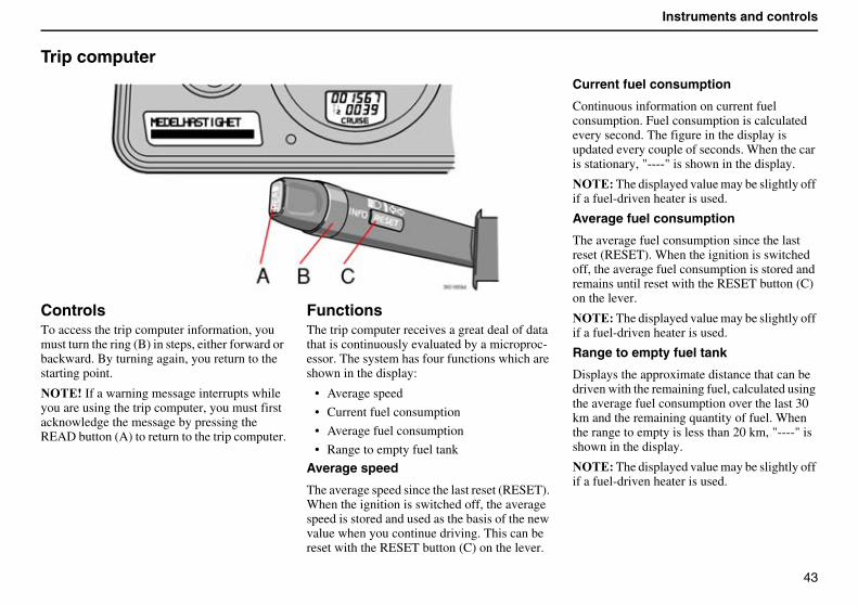
ControlsTo access the trip computer information, you must turn the ring (B) in steps, either forward or backward. By turning again, you return to the starting point.
������If a warning message interrupts while you are using the trip computer, you must first acknowledge the message by pressing the READ button (A) to return to the trip computer.
FunctionsThe trip computer receives a great deal of data that is continuously evaluated by a microproc-essor. The system has four functions which are shown in the display:
• Average speed
• Current fuel consumption
• Average fuel consumption
• Range to empty fuel tank
Average speed
The average speed since the last reset (RESET). When the ignition is switched off, the average speed is stored and used as the basis of the new value when you continue driving. This can be reset with the RESET button (C) on the lever.
Current fuel consumption
Continuous information on current fuel consumption. Fuel consumption is calculated every second. The figure in the display is updated every couple of seconds. When the car is stationary, "----" is shown in the display.
������The displayed value may be slightly off if a fuel-driven heater is used.
Average fuel consumption
The average fuel consumption since the last reset (RESET). When the ignition is switched off, the average fuel consumption is stored and remains until reset with the RESET button (C) on the lever.
������The displayed value may be slightly off if a fuel-driven heater is used.
Range to empty fuel tank
Displays the approximate distance that can be driven with the remaining fuel, calculated using the average fuel consumption over the last 30 km and the remaining quantity of fuel. When the range to empty is less than 20 km, "----" is shown in the display.
������The displayed value may be slightly off if a fuel-driven heater is used.
44
Instruments and controls
Cruise control
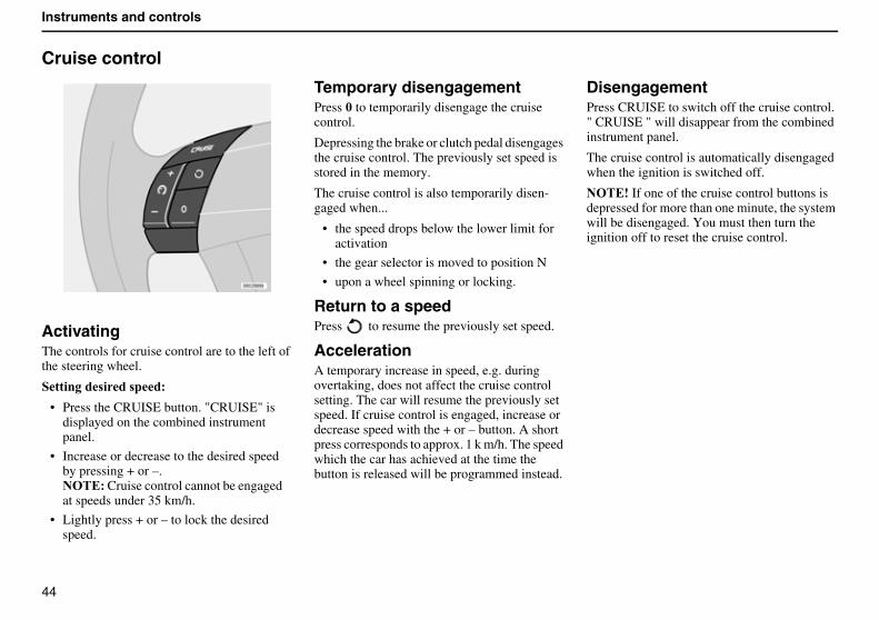
ActivatingThe controls for cruise control are to the left of the steering wheel.
�������� ��� ���
• Press the CRUISE button. "CRUISE" is displayed on the combined instrument panel.
• Increase or decrease to the desired speed by pressing + or –.����� Cruise control cannot be engaged at speeds under 35 km/h.
• Lightly press + or – to lock the desired speed.
Temporary disengagementPress 5 to temporarily disengage the cruise control.
Depressing the brake or clutch pedal disengages the cruise control. The previously set speed is stored in the memory.
The cruise control is also temporarily disen-gaged when...
• the speed drops below the lower limit for activation
• the gear selector is moved to position N
• upon a wheel spinning or locking.
Return to a speedPress to resume the previously set speed.
AccelerationA temporary increase in speed, e.g. during overtaking, does not affect the cruise control setting. The car will resume the previously set speed. If cruise control is engaged, increase or decrease speed with the + or – button. A short press corresponds to approx. 1 k m/h. The speed which the car has achieved at the time the button is released will be programmed instead.
DisengagementPress CRUISE to switch off the cruise control. " CRUISE " will disappear from the combined instrument panel.
The cruise control is automatically disengaged when the ignition is switched off.
������If one of the cruise control buttons is depressed for more than one minute, the system will be disengaged. You must then turn the ignition off to reset the cruise control.
45
Instruments and controls
Parking brake, bonnet, electric socket, etc.
��� �������"��8%���
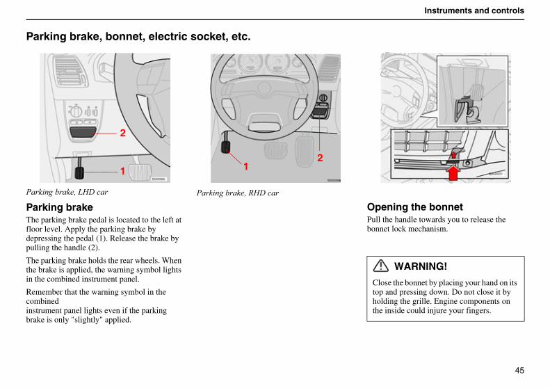
Parking brakeThe parking brake pedal is located to the left at floor level. Apply the parking brake by depressing the pedal (1). Release the brake by pulling the handle (2).
The parking brake holds the rear wheels. When the brake is applied, the warning symbol lights in the combined instrument panel.
Remember that the warning symbol in the combinedinstrument panel lights even if the parking brake is only "slightly" applied.
��� �������"��8%���
Opening the bonnetPull the handle towards you to release the bonnet lock mechanism.
WARNING!
Close the bonnet by placing your hand on its top and pressing down. Do not close it by holding the grille. Engine components on the inside could injure your fingers.
2
1 12
46
Instruments and controls
Parking brake, bonnet, electric socket, etc. (Contd)
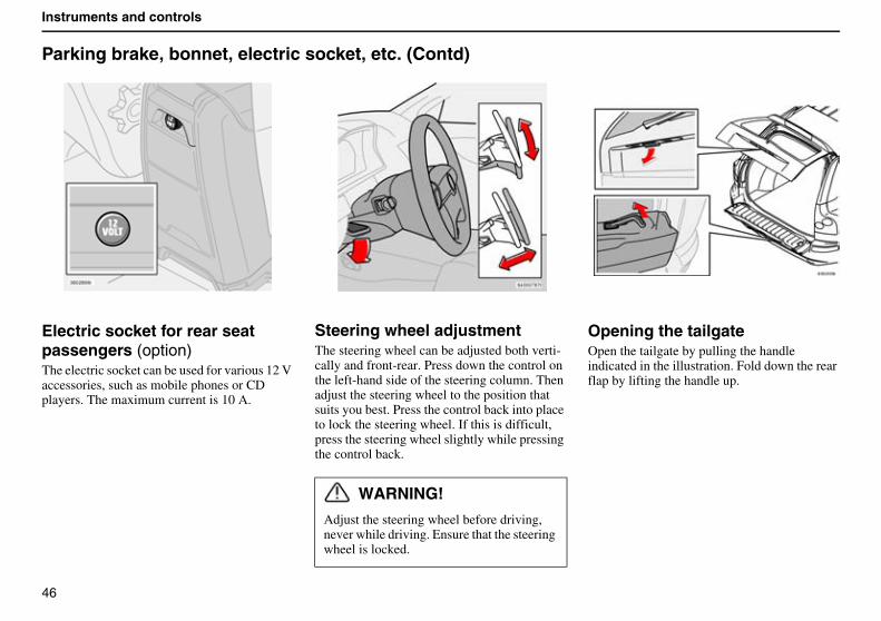
Electric socket for rear seat passengers (option)The electric socket can be used for various 12 V accessories, such as mobile phones or CD players. The maximum current is 10 A.
Steering wheel adjustmentThe steering wheel can be adjusted both verti-cally and front-rear. Press down the control on the left-hand side of the steering column. Then adjust the steering wheel to the position that suits you best. Press the control back into place to lock the steering wheel. If this is difficult, press the steering wheel slightly while pressing the control back.
Opening the tailgateOpen the tailgate by pulling the handle indicated in the illustration. Fold down the rear flap by lifting the handle up.
WARNING!
Adjust the steering wheel before driving, never while driving. Ensure that the steering wheel is locked.
47
Instruments and controls
Power windows
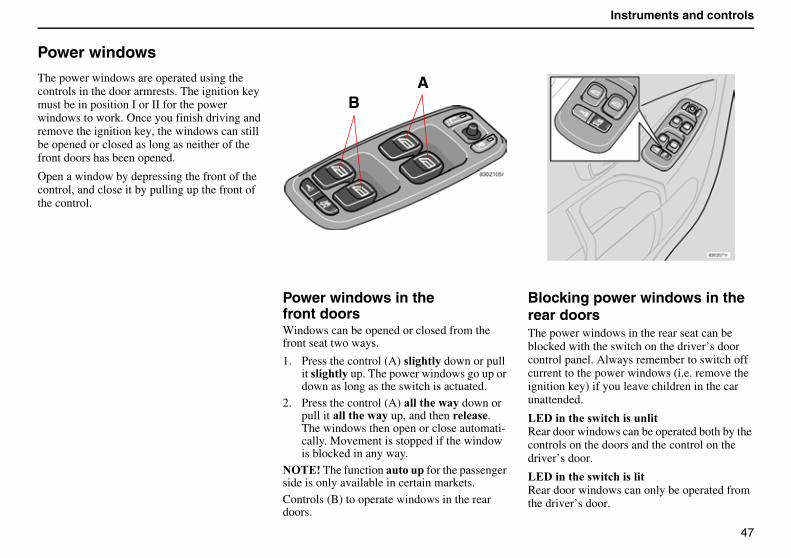
The power windows are operated using the controls in the door armrests. The ignition key must be in position I or II for the power windows to work. Once you finish driving and remove the ignition key, the windows can still be opened or closed as long as neither of the front doors has been opened.
Open a window by depressing the front of the control, and close it by pulling up the front of the control.
Power windows in thefront doorsWindows can be opened or closed from the front seat two ways.
1. Press the control (A) ��������down or pull it� ������� up. The power windows go up or down as long as the switch is actuated.
2. Press the control (A) �����������down or pull it �����������up, and then �� . The windows then open or close automati-cally. Movement is stopped if the window is blocked in any way.
������The function ������� for the passenger side is only available in certain markets.Controls (B) to operate windows in the rear doors.
Blocking power windows in the rear doorsThe power windows in the rear seat can be blocked with the switch on the driver’s door control panel. Always remember to switch off current to the power windows (i.e. remove the ignition key) if you leave children in the car unattended.
&��������� ���!��� �������Rear door windows can be operated both by the controls on the doors and the control on the driver’s door.
&��������� ���!��� �����Rear door windows can only be operated from the driver’s door.
BA
48
Instruments and controls
Power windows (Contd)
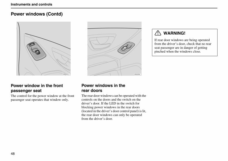
Power window in the frontpassenger seatThe control for the power window at the front passenger seat operates that window only.
Power windows in therear doorsThe rear door windows can be operated with the controls on the doors and the switch on the driver’s door. If the LED in the switch for blocking power windows in the rear doors (located in the driver’s door control panel) is lit, the rear door windows can only be operated from the driver’s door.
WARNING!
If rear door windows are being operated from the driver’s door, check that no rear seat passenger are in danger of getting pinched when the windows close.
49
Instruments and controls
Rearview mirror/door mirrors
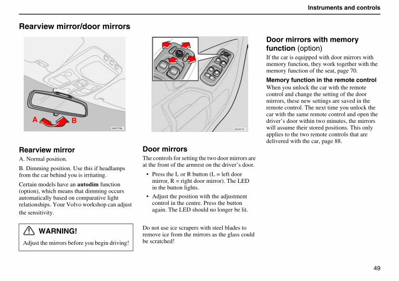
Rearview mirrorA. Normal position.
B. Dimming position. Use this if headlamps from the car behind you is irritating.
Certain models have an ������'�function (option), which means that dimming occurs automatically based on comparative light relationships. Your Volvo workshop can adjust the sensitivity.
Door mirrorsThe controls for setting the two door mirrors are at the front of the armrest on the driver’s door.
• Press the L or R button (L = left door mirror, R = right door mirror). The LED in the button lights.
• Adjust the position with the adjustment control in the centre. Press the button again. The LED should no longer be lit.
Do not use ice scrapers with steel blades to remove ice from the mirrors as the glass could be scratched!
Door mirrors with memory function (option) If the car is equipped with door mirrors with memory function, they work together with the memory function of the seat, page 70.
Memory function in the remote controlWhen you unlock the car with the remote control and change the setting of the door mirrors, these new settings are saved in the remote control. The next time you unlock the car with the same remote control and open the driver’s door within two minutes, the mirrors will assume their stored positions. This only applies to the two remote controls that are delivered with the car, page 88.
WARNING!
Adjust the mirrors before you begin driving!
A B
50
Instruments and controls
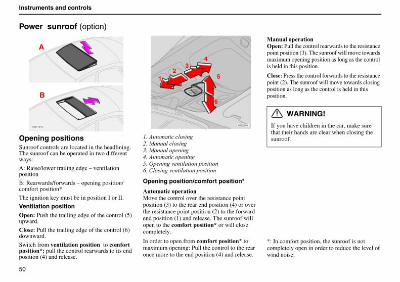
Power sunroof (option)
Opening positionsSunroof controls are located in the headlining. The sunroof can be operated in two different ways:
A: Raise/lower trailing edge – ventilation position
B: Rearwards/forwards – opening position/comfort position*
The ignition key must be in position I or II.
Ventilation position���� Push the trailing edge of the control (5) upward.
"�� ��Pull the trailing edge of the control (6) downward.
Switch from ������������� ������ to !�' ����� �����?� pull the control rearwards to its end position (4) and release.
.��('��!�� ����� ��0�����'����� ��-�����'������ ��9��('��!�� ������ ��+��4��� ������� �� ������ � ��/����� ������� �� ������ � ��
Opening position/comfort position*
����'���!���������Move the control over the resistance point position (3) to the rear end position (4) or over the resistance point position (2) to the forward end position (1) and release. The sunroof will open to the !�' ����� �����? or will close completely.
In order to open from !�' ����� �����? to maximum opening: Pull the control to the rear once more to the end position (4) and release.
0����������������� Pull the control rearwards to the resistance point position (3). The sunroof will move towards maximum opening position as long as the control is held in this position.
"�� � Press the control forwards to the resistance point (2). The sunroof will move towards closing position as long as the control is held in this position.
*: In comfort position, the sunroof is not completely open in order to reduce the level of wind noise.
WARNING!
If you have children in the car, make sure that their hands are clear when closing the sunroof.
A
B
12
34
6
5
51
Instruments and controls
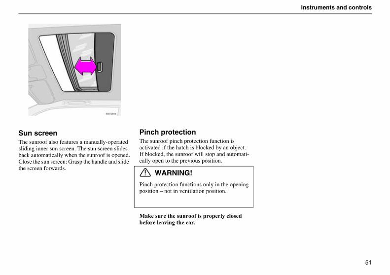
Sun screenThe sunroof also features a manually-operated sliding inner sun screen. The sun screen slides back automatically when the sunroof is opened.Close the sun screen: Grasp the handle and slide the screen forwards.
Pinch protectionThe sunroof pinch protection function is activated if the hatch is blocked by an object.If blocked, the sunroof will stop and automati-cally open to the previous position.
WARNING!
Pinch protection functions only in the opening position – not in ventilation position.
0�#� ����� ���� �� �������!�� ��� ������������!�$�

52
Instruments and controls
53
Climate control
General on climate control 54
Manual climate control with air conditioning, AC 56
Electronic Climate Control (ECC) 60
Parking heater (option) 64
54
Climate control
General on climate control
Misting on window interiorsA good way to reduce the problem of misting on the insides of the windscreen and other windows is to clean them. Use a normal window cleaner.Bear in mind that you must clean them more often if someone smokes in the car.
Particle filterMake sure the particle filter is replaced regularly. Consult your Volvo workshop.
Ice and snowRemove ice and snow from the climate control air intake (the grille between the bonnet and the windscreen).
Fault tracingYour Volvo workshop has the instruments and tools required for any fault tracing or repair of your climate control system. Entrust checks and repairs only to trained personnel.
Environmental careRefrigerant R134a is in the air conditioning system. This contains no chlorine, which means it is harmless to the ozone layer.
Only use R134a when filling/changing refrig-erant. This work should be carried out by an accredited workshop.
Cars with ECCActual temperature – ECCThe temperature you select corresponds to the physical experience with reference to air speed, humidity, exposure to sun, etc. which affect the interior and exterior of the car.
Sensors – ECCThe sun sensor is on the upper portion of the dashboard. Remember not to cover it.Do not cover the passenger compartment temperature sensor on the climate control panel.
Side windows and sunroofTo ensure that the air conditioning works satis-factorily, close all side windows and the sunroof (if fitted).
AccelerationThe air conditioning system switches off temporarily at full acceleration. You may feel a temporary rise in temperature.
Condensation/Drying
In warm weather, condensation from the air conditioning system may drip under the car. This is normal. If necessary, the fan willstart 50 minutes after the ignition switch is turned to position 0 to dry the climate control system for seven minutes. The fan then switches off automatically.
Fuel economy - Electronic climate control ECCWith ECC, the air conditioning system is controlled automatically and is used just enough to cool the passenger compartment and dehumidify the incoming air. This provides better fuel economy compared to conventional systems where the air conditioning cools the air to just above freezing point.
Fan function to reduce risk of battery discharge
When the engine is switched off (even if the ignition key is in position I or II), the fan will be switched off automatically. To activate the fan, turn the knob and set the desired speed. After two minutes, the fan will reduce to a lower speed. This is one way to avoid discharging the battery when the engine is switched off.
55
Climate control
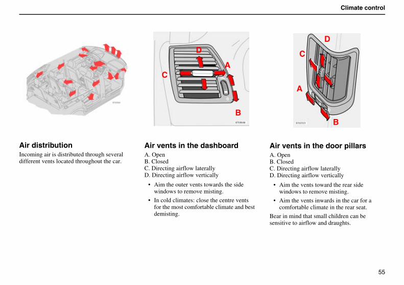
Air distributionIncoming air is distributed through several different vents located throughout the car.
Air vents in the dashboardA. OpenB. ClosedC. Directing airflow laterallyD. Directing airflow vertically
• Aim the outer vents towards the side windows to remove misting.
• In cold climates: close the centre vents for the most comfortable climate and best demisting.
Air vents in the door pillarsA. OpenB. ClosedC. Directing airflow laterallyD. Directing airflow vertically
• Aim the vents toward the rear side windows to remove misting.
• Aim the vents inwards in the car for a comfortable climate in the rear seat.
Bear in mind that small children can be sensitive to airflow and draughts.
A
B
C
D
A
B
C
D
56
Climate control
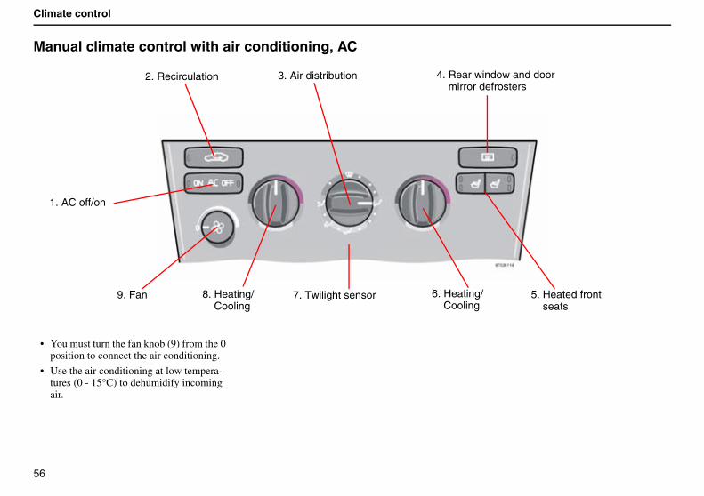
Manual climate control with air conditioning, AC
• You must turn the fan knob (9) from the 0 position to connect the air conditioning.
• Use the air conditioning at low tempera-tures (0 - 15°C) to dehumidify incoming air.
1. AC off/on
2. Recirculation 3. Air distribution 4. Rear window and door mirror defrosters
8. Heating/Cooling
6. Heating/Cooling
9. Fan 5. Heated front seats
7. Twilight sensor
57
Climate control
1. AC - ON/OFFThe air conditioning is connected to the cooling and dehumidification function with the ON LED lights. The air conditioning is discon-nected with the OFF LED lights.
When you select Defroster , the air condi-tioning is connected as long as the fan is not set to position 0.
2. RecirculationRecirculation can be used to shut out bad air, exhaust, etc. from the passenger compartment. The air in the passenger compartment is then recirculated, i.e. no air from outside the car is taken into the car when this function is activated. Recirculation (together with the air conditioning system) cools the passenger compartment more quickly in a warm climate.
If you allow the air in the car to recirculate, there is a risk of icing and misting, especially in winter. The timer function minimises the risk of ice, misting and bad air.
Activate the function as follows:
• Press for more than 3 seconds. The LED flashes for 5 seconds. The air recir-culates in the car for 3-12 minutes depending on the outside temperature.
• The timer function is activated each time you press .
To switch off the timer function:
• Press again for more than 3 seconds. The LED lights for 5 seconds to confirm your selection.
Recirculation is always disconnected when you select Defroster.
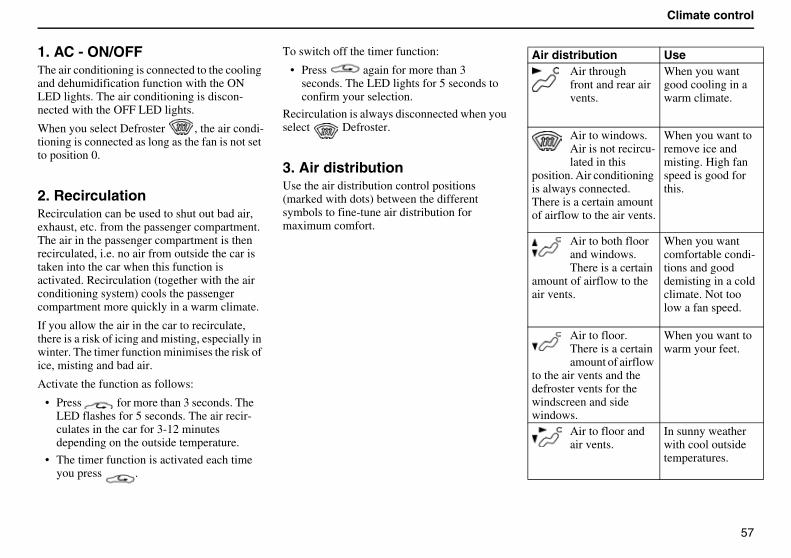
3. Air distributionUse the air distribution control positions (marked with dots) between the different symbols to fine-tune air distribution for maximum comfort.
Air distribution UseAir throughfront and rear air vents.
When you want good cooling in a warm climate.
Air to windows.Air is not recircu-lated in this
position. Air conditioning is always connected. There is a certain amount of airflow to the air vents.
When you want to remove ice and misting. High fan speed is good for this.
Air to both floor and windows. There is a certain
amount of airflow to the air vents.
When you want comfortable condi-tions and good demisting in a cold climate. Not too low a fan speed.
Air to floor. There is a certain amount of airflow
to the air vents and thedefroster vents for the windscreen and side windows.
When you want to warm your feet.
Air to floor and air vents.
In sunny weather with cool outside temperatures.
58
Climate control
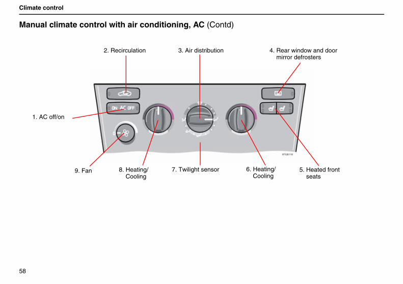
Manual climate control with air conditioning, AC (Contd)
2. Recirculation 3. Air distribution 4. Rear window and door mirror defrosters
8. Heating/Cooling
6. Heating/Cooling
9. Fan 5. Heated front seats
7. Twilight sensor
1. AC off/on
59
Climate control
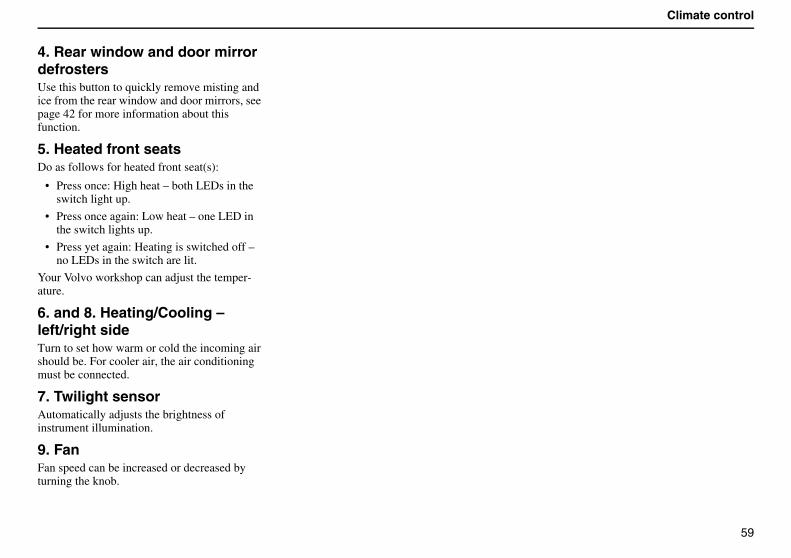
4. Rear window and door mirror defrostersUse this button to quickly remove misting and ice from the rear window and door mirrors, see page 42 for more information about this function.
5. Heated front seatsDo as follows for heated front seat(s):
• Press once: High heat – both LEDs in the switch light up.
• Press once again: Low heat – one LED in the switch lights up.
• Press yet again: Heating is switched off –no LEDs in the switch are lit.
Your Volvo workshop can adjust the temper-ature.
6. and 8. Heating/Cooling –left/right sideTurn to set how warm or cold the incoming air should be. For cooler air, the air conditioning must be connected.
7. Twilight sensorAutomatically adjusts the brightness of instrument illumination.
9. FanFan speed can be increased or decreased by turning the knob.
60
Climate control
Electronic Climate Control (ECC)
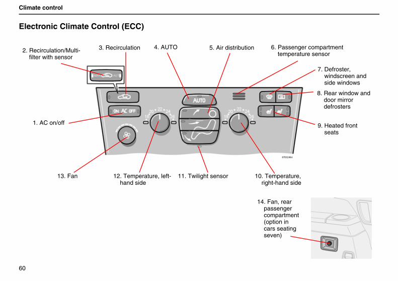
1. AC on/off
2. Recirculation/Multi-filter with sensor
3. Recirculation 4. AUTO 5. Air distribution 6. Passenger compartment temperature sensor
7. Defroster, windscreen and side windows
8. Rear window and door mirror defrosters
9. Heated frontseats
10. Temperature, right-hand side
11. Twilight sensor12. Temperature, left-hand side
13. Fan
14. Fan, rear passenger compartment (option in cars seating seven)
61
Climate control
1. AC – ON/OFFThe air conditioning system is controlled automatically by the system when the ON LED is lit. This way, incoming air is cooled and dehumidified sufficiently. When AC OFF is selected and the OFF LED lights, the air condi-tioning system is disconnected; other functions are still controlled automatically. The air condi-tioning system operates down to approximately 0°C.
When you select Defroster, the air conditioning system is controlled so that air is maximally dehumidified.
2. Air quality sensor with multi-filter (option in certain markets)Certain cars are equipped with a "Multifilter" and air quality sensor. The Multifilter separates gases and particles, thus reducing the volume of odours and pollutants entering the car. The air quality sensor detects increased levels of contaminants in the outside air. When the air quality sensor detects contaminated outside air, the air intake is closed and the air in the compartment is recirculated. The Multifilter also cleans the air recirculating in the compartment.
When the air quality sensor is active, the green AUT LED lights in .
Operation
Press to activate the airquality sensor (normal setting).
Or:
Select one of the following three functions by pressing repeatedly.
• AUT LED lit: The air quality sensor is now activated.
• No LED lit: Recirculation is not activated unless needed to cool in a warm climate.
• MAN LED lit: Recirculation is now activated.
Keep in mind the following:
• Make it a rule to have the air quality sensor activated at all times.
• Recirculation is limited in cold climates to avoid misting.
• If misting occurs, you should deactivate the air quality sensor.
• If misting occurs, you can use the defroster functions for the windscreen, side windows and rear window. See page 63.
• Follow the Volvo Service Programme for the recommended replacement interval of the Multifilter. If the car is used in a severely contaminated environment, it may be necessary to change the Multi-filter more often.
62
Climate control
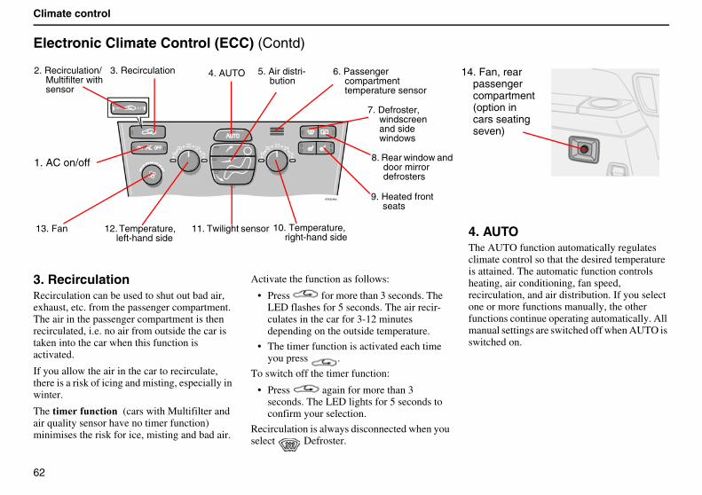
Electronic Climate Control (ECC) (Contd)
3. RecirculationRecirculation can be used to shut out bad air, exhaust, etc. from the passenger compartment. The air in the passenger compartment is then recirculated, i.e. no air from outside the car is taken into the car when this function is activated.
If you allow the air in the car to recirculate, there is a risk of icing and misting, especially in winter.
The ������������ (cars with Multifilter and air quality sensor have no timer function) minimises the risk for ice, misting and bad air.
Activate the function as follows:
• Press for more than 3 seconds. The LED flashes for 5 seconds. The air recir-culates in the car for 3-12 minutes depending on the outside temperature.
• The timer function is activated each time you press .
To switch off the timer function:
• Press again for more than 3 seconds. The LED lights for 5 seconds to confirm your selection.
Recirculation is always disconnected when you select Defroster.
4. AUTO The AUTO function automatically regulates climate control so that the desired temperature is attained. The automatic function controls heating, air conditioning, fan speed,recirculation, and air distribution. If you select one or more functions manually, the other functions continue operating automatically. All manual settings are switched off when AUTO is switched on.
1. AC on/off
2. Recirculation/Multifilter with sensor
3. Recirculation 4. AUTO 5. Air distri-bution
6. Passenger compartment temperature sensor
7. Defroster, windscreen and side windows
8. Rear window and door mirror defrosters
9. Heated front seats
10. Temperature,right-hand side
11. Twilight sensor12. Temperature, left-hand side
13. Fan
14. Fan, rear passenger compartment (option in cars seating seven)
63
Climate control
5. Air distribution• When the top button is depressed, air is
directed to the windows.
• When the centre button is depressed, air is directed to the head and body.
• When the lower button is depressed, air is directed to the legs and feet.
Press AUTO to return to automatic air distri-bution.
6. Passenger compartment temperature sensorThe passenger compartment temperature sensor monitors the temperature inside the car.
7. Defroster – windscreen and side windowsUse this button to quickly remove misting and ice from the windscreen and side windows. The air flows to the windows at high fan speed. The LED in the defroster button lights when this function is activated. The air conditioning system is now controlled so that the air is maximally dehumidified. The air is not recircu-lated.
8. Rear window and door mirror defrostersUse this button to quickly remove misting and ice from the rear window and door mirrors, see page 42 for more information about this function.
9. Heated front seatsDo as follows for heated front seat(s):
• Press once: High heat – both LEDs in the switch light up.
• Press once again: Low heat – one LED in the switch lights up.
• Press yet again: Heating is switched off - no LEDs in the switch are lit.
Your Volvo workshop can adjust the temper-ature.
10 and 12. TemperatureThe two knobs can be used to set the temper-ature for the passenger and driver’s sides of the car. Remember that the car does not heat up or cool down any more quickly even if you select a higher or lower temperature than you want in the passenger compartment.
11. Twilight sensorAutomatically adjusts the brightness of instrument illumination.
13. FanFan speed can be increased or decreased by turning the knob. If AUTO is selected, fan speed is controlled automatically. The previ-ously set fan speed is disconnected.
If the knob for the fan is turned so far to the left that only the left LED above the knob lights with an orange glow, the fan and air condi-tioning are switched off.
14. Fan, rear passenger compartmentFan speed can be increased or decreased by turning the knob. This only applies if AC is selected in both the front (1) and rear; see page 37.
64
Climate control
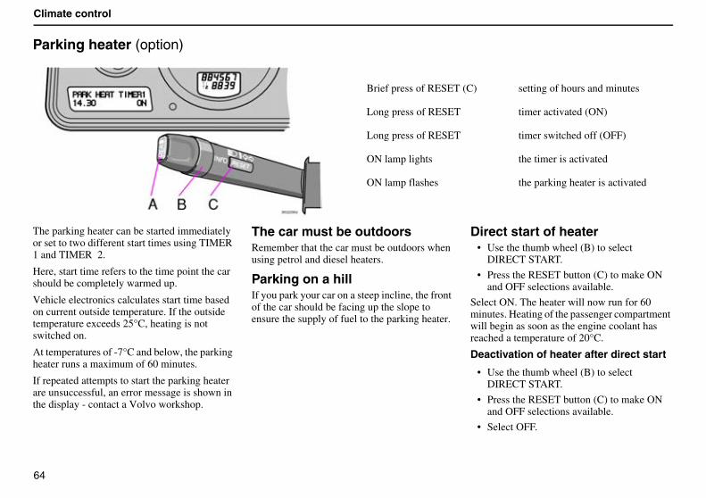
Parking heater (option)
The parking heater can be started immediately or set to two different start times using TIMER 1 and TIMER 2.
Here, start time refers to the time point the car should be completely warmed up.
Vehicle electronics calculates start time based on current outside temperature. If the outside temperature exceeds 25°C, heating is not switched on.
At temperatures of -7°C and below, the parking heater runs a maximum of 60 minutes.
If repeated attempts to start the parking heater are unsuccessful, an error message is shown in the display - contact a Volvo workshop.
The car must be outdoorsRemember that the car must be outdoors when using petrol and diesel heaters.
Parking on a hillIf you park your car on a steep incline, the front of the car should be facing up the slope to ensure the supply of fuel to the parking heater.
Direct start of heater• Use the thumb wheel (B) to select
DIRECT START.
• Press the RESET button (C) to make ON and OFF selections available.
Select ON. The heater will now run for 60 minutes. Heating of the passenger compartment will begin as soon as the engine coolant has reached a temperature of 20°C.
Deactivation of heater after direct start
• Use the thumb wheel (B) to select DIRECT START.
• Press the RESET button (C) to make ON and OFF selections available.
• Select OFF.
Brief press of RESET (C) setting of hours and minutes
Long press of RESET timer activated (ON)
Long press of RESET timer switched off (OFF)
ON lamp lights the timer is activated
ON lamp flashes the parking heater is activated
65
Climate control
Setting TIMER 1 or 2For reasons of safety, you can only programme times for the following 24 hours, not several days in a row.
1. Use the thumb wheel (B) to select TIMER 1.
2. Briefly press the RESET button (C) so that the hours setting starts to flash.
3. Use the thumb wheel to set the desired number of hours.
4. Give the RESET button (C) a short press to come to the flashing minutes setting.
5. Use the thumb wheel to set the desired number of minutes.
6. Give the RESET button (C) a short press to confirm your setting.
7. Press the RESET button (C) to activate the timer.
Once you have set TIMER 1 you can toggle to TIMER 2. Make settings the same way as for TIMER 1.
Deactivation of timer-started heater
Do as follows to manually switch off the heater before the set time has elapsed:
1. Press the READ button (A)
2. Use the thumb wheel (B) to scroll to the text PARK HEAT TIMER 1 or 2. The text ON flashes.
3. Press the RESET button (C). The text OFF is displayed with a steady glow and the heater is switched off.
Messages in the displayOnce TIMER 1, TIMER 2 and Immediate start are activated, the amber symbol in the combined instrument panel lights and explan-atory text is shown in the display.
When you leave the car, you will receive a message regarding the current settings of the system.
Car clock/timerFor reasons of safety, all timer settings will be deactivated if the car clock is reset after timer settings have been made.
Battery and fuelIf the battery is not sufficiently charged or the petrol tank is close to empty, the parking heater will be switched off.
If this is the case, you will receive a message in the display. Confirm the message using the READ button (A).
Important!
Repeated use of the parking heater in combi-nation with short trips can lead to battery discharge and thereby difficulty starting.
If the heater is used regularly, the car should be driven for the same amount of time as the heater was used in order to ensure that the generator is able to produce enough energy to compensate for the amount consumed.

66
Climate control
67
Interior
Front seats 68
Rear seats 72
Interior lighting 74
Storage compartments in the passenger compartment 76
Cargo compartmen 80
cargo compartment 85
Warning triangle (certain countries) 86
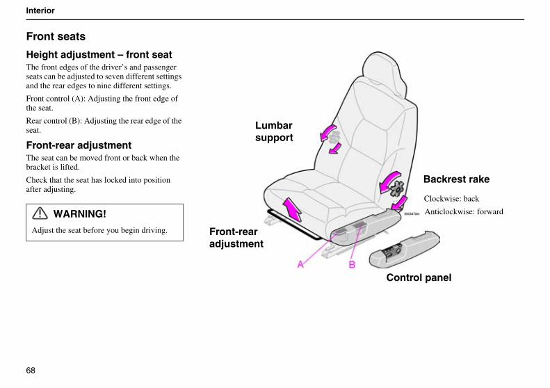
68
Interior
Front seats
Height adjustment – front seatThe front edges of the driver’s and passenger seats can be adjusted to seven different settings and the rear edges to nine different settings.
Front control (A): Adjusting the front edge of the seat.
Rear control (B): Adjusting the rear edge of the seat.
Front-rear adjustmentThe seat can be moved front or back when the bracket is lifted.
Check that the seat has locked into position after adjusting.
WARNING!
Adjust the seat before you begin driving.
Backrest rake
Clockwise: back
Anticlockwise: forward
Lumbar
Front-rear
Control panel
support
adjustment
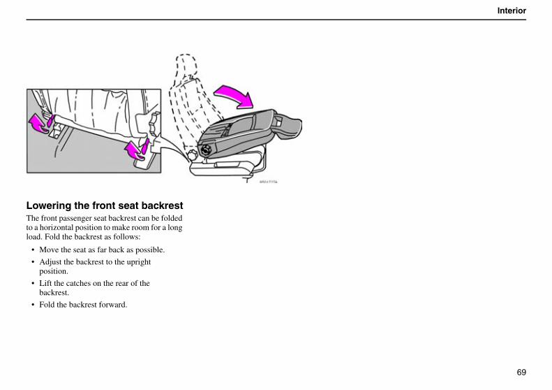
69
Interior
Lowering the front seat backrestThe front passenger seat backrest can be folded to a horizontal position to make room for a long load. Fold the backrest as follows:
• Move the seat as far back as possible.
• Adjust the backrest to the upright position.
• Lift the catches on the rear of the backrest.
• Fold the backrest forward.
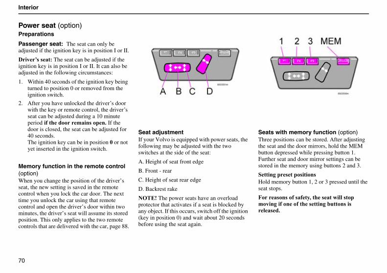
70
Interior
Power seat (option)Preparations
Passenger seat: The seat can only be adjusted if the ignition key is in position I or II.
���@ � ��� The seat can be adjusted if the ignition key is in position I or II. It can also be adjusted in the following circumstances:
1. Within 40 seconds of the ignition key being turned to position 0 or removed from the ignition switch.
2. After you have unlocked the driver’s door with the key or remote control, the driver’s seat can be adjusted during a 10 minute period � ��������'��� ����$ If the door is closed, the seat can be adjusted for 40 seconds.The ignition key can be in position 5 or not yet inserted in the ignition switch.
Memory function in the remote control (option)When you change the position of the driver’s seat, the new setting is saved in the remote control when you lock the car door. The next time you unlock the car using that remote control and open the driver’s door within two minutes, the driver’s seat will assume its stored position. This only applies to the two remote controls that are delivered with the car, page 88.
Seat adjustmentIf your Volvo is equipped with power seats, the following may be adjusted with the two switches at the side of the seat:
A. Height of seat front edge
B. Front - rear
C. Height of seat rear edge
D. Backrest rake
������The power seats have an overload protector that activates if a seat is blocked by any object. If this occurs, switch off the ignition (key in position 0) and wait about 20 seconds before using the seat again.
Seats with memory function (option) Three positions can be stored. After adjusting the seat and the door mirrors, hold the MEM button depressed while pressing button 1. Further seat and door mirror settings can be stored in the memory using buttons 2 and 3.
�������� ���� ����� Hold memory button 1, 2 or 3 pressed until the seat stops.
7��� �� �� � � ��,���� �������� ����'������� ����� ���� ������������ �� ��� �$
71
Interior
Emergency stop
If the seat accidentally begins to move, press one of the buttons to stop the seat.
WARNING!
When adjusting, ensure that there are no objects in front of or behind the seat. Ensure that none of the rear seat passengers will be pinched. To avoid this possibility, ensure that children do not play with the switches.
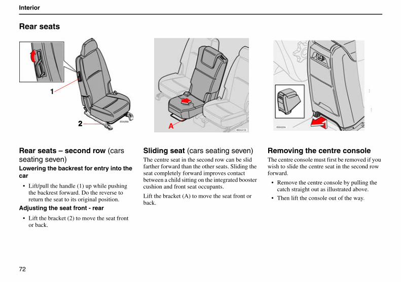
72
Interior
Rear seats
Rear seats – second row (cars seating seven)Lowering the backrest for entry into the car
• Lift/pull the handle (1) up while pushing the backrest forward. Do the reverse to return the seat to its original position.
Adjusting the seat front - rear
• Lift the bracket (2) to move the seat front or back.
Sliding seat (cars seating seven)The centre seat in the second row can be slid farther forward than the other seats. Sliding the seat completely forward improves contact between a child sitting on the integrated booster cushion and front seat occupants.
Lift the bracket (A) to move the seat front or back.
Removing the centre consoleThe centre console must first be removed if you wish to slide the centre seat in the second row forward.
• Remove the centre console by pulling the catch straight out as illustrated above.
• Then lift the console out of the way.
1
22 A
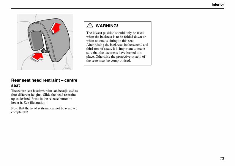
73
Interior
Rear seat head restraint – centre seatThe centre seat head restraint can be adjusted to four different heights. Slide the head restraint up as desired. Press in the release button to lower it. See illustration!
Note that the head restraint cannot be removed completely!
WARNING!
The lowest position should only be used when the backrest is to be folded down or when no one is sitting in this seat.After raising the backrests in the second and third row of seats, it is important to make sure that the backrests have locked into place. Otherwise the protective system of the seats may be compromised.
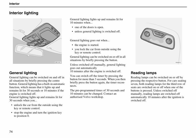
74
Interior
Interior lighting
General lightingGeneral lighting can be switched on and off in all situations by briefly pressing the centre button. General lighting has a built-in automatic function, which means that it lights up and remains lit for 30 seconds or 10 minutes if the engine is switched off.General lighting lights up and remains lit for30 seconds when you...
• unlock the car from the outside using the key or remote control.
• stop the engine and turn the ignition key to position 0.
General lighting lights up and remains lit for10 minutes when...
• one of the doors is open.
• unless general lighting is switched off.
General lighting goes out when...
• the engine is started.
• you lock the car from outside using the key or remote control.
General lighting can be switched on or off in all situations by briefly pressing the button.
Unless switched off manually, general lighting goes out automatically10 minutes after the engine is switched off.
You can switch off the timer by pressing the button for more than 3 seconds. When you then briefly press the button again, the timer recon-nects.
The pre-programmed times of 30 seconds and10 minutes can be changed. Contact an authorised Volvo workshop.
Reading lampsReading lamps can be switched on or off by pressing the respective button. For cars seating seven, both reading lamps for the third row of seats are switched on or off when one of the buttons is pressed. Unless switched off manually, reading lamps are switched off automatically 10 minutes after the ignition is switched off.
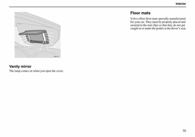
75
Interior
Vanity mirrorThe lamp comes on when you open the cover.
Floor matsVolvo offers floor mats specially manufactured for your car. They must be properly placed and secured in the mat clips so that they do not get caught in or under the pedals at the driver’s seat.
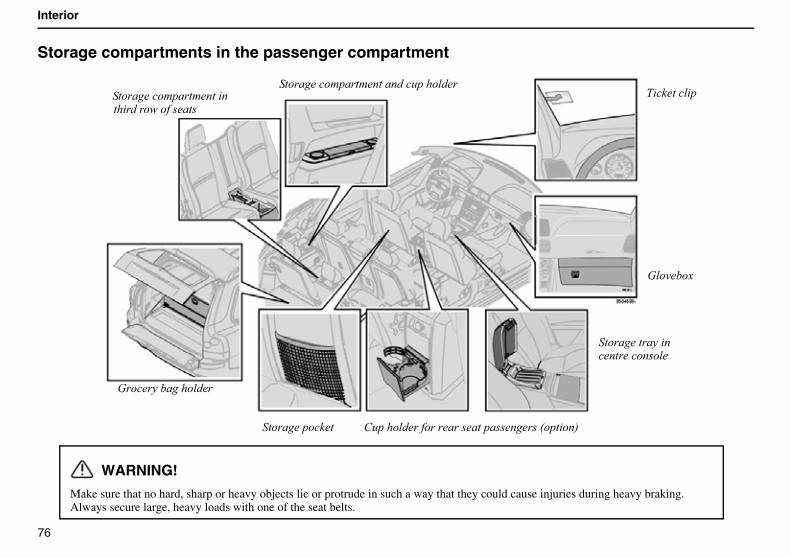
76
Interior
Storage compartments in the passenger compartment
WARNING!
Make sure that no hard, sharp or heavy objects lie or protrude in such a way that they could cause injuries during heavy braking.Always secure large, heavy loads with one of the seat belts.
:��� ���������
$ ������ �
:������
��������� � ��
�'����������������������������;��� ��<�������������
������������
���������!���!���������'���������������!���!���� ���� �������������
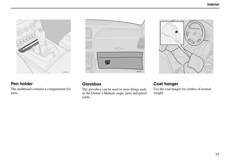
77
Interior
Pen holderThe dashboard contains a compartment for pens.
GloveboxThe glovebox can be used to store things such as the Owner’s Manual, maps, pens and petrol cards.
Coat hangerUse the coat hanger for clothes of normal weight.
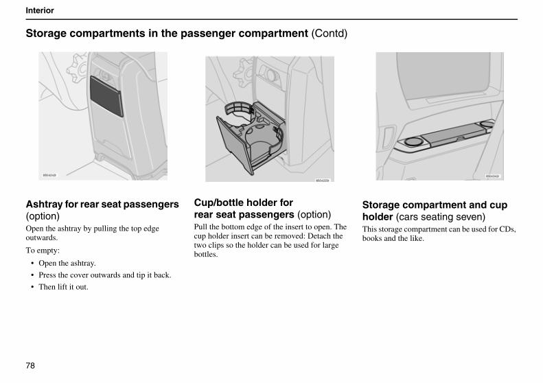
78
Interior
Storage compartments in the passenger compartment (Contd)
Ashtray for rear seat passengers (option)Open the ashtray by pulling the top edge outwards.
To empty:
• Open the ashtray.
• Press the cover outwards and tip it back.
• Then lift it out.
Cup/bottle holder forrear seat passengers (option)Pull the bottom edge of the insert to open. The cup holder insert can be removed: Detach the two clips so the holder can be used for large bottles.
Storage compartment and cup holder (cars seating seven)This storage compartment can be used for CDs, books and the like.
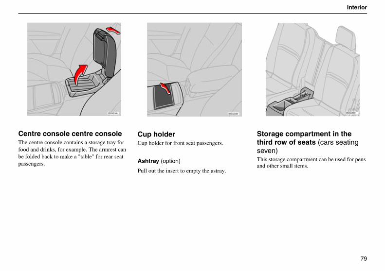
79
Interior
Centre console centre consoleThe centre console contains a storage tray for food and drinks, for example. The armrest can be folded back to make a "table" for rear seat passengers.
Cup holderCup holder for front seat passengers.
Ashtray (option)
Pull out the insert to empty the astray.
Storage compartment in the third row of seats (cars seating seven) This storage compartment can be used for pens and other small items.
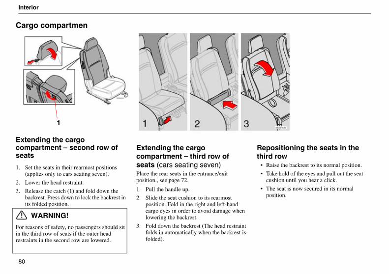
80
Interior
Cargo compartmen
Extending the cargo compartment – second row of seats
1. Set the seats in their rearmost positions (applies only to cars seating seven).
2. Lower the head restraint.
3. Release the catch (1) and fold down the backrest. Press down to lock the backrest in its folded position.
WARNING!
For reasons of safety, no passengers should sit in the third row of seats if the outer head restraints in the second row are lowered.
Extending the cargo compartment – third row of seats (cars seating seven)Place the rear seats in the entrance/exit position., see page 72.
1. Pull the handle up.
2. Slide the seat cushion to its rearmost position. Fold in the right and left-hand cargo eyes in order to avoid damage when lowering the backrest.
3. Fold down the backrest (The head restraint folds in automatically when the backrest is folded).
Repositioning the seats in the third row
• Raise the backrest to its normal position.
• Take hold of the eyes and pull out the seat cushion until you hear a click.
• The seat is now secured in its normal position.
1
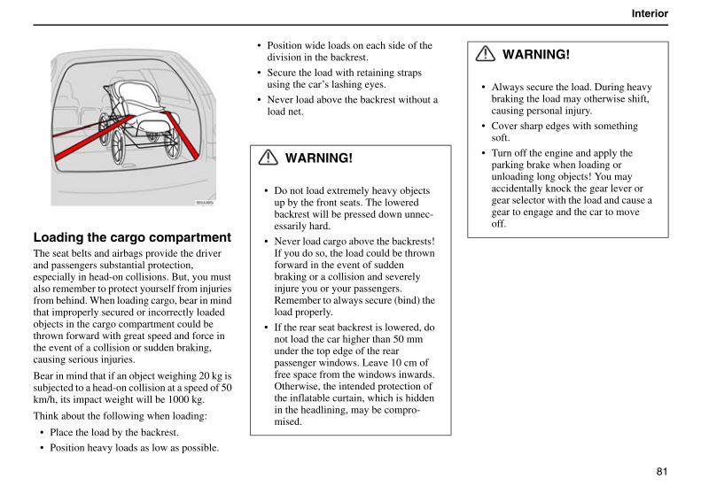
81
Interior
Loading the cargo compartmentThe seat belts and airbags provide the driver and passengers substantial protection, especially in head-on collisions. But, you must also remember to protect yourself from injuries from behind. When loading cargo, bear in mind that improperly secured or incorrectly loaded objects in the cargo compartment could be thrown forward with great speed and force in the event of a collision or sudden braking, causing serious injuries.
Bear in mind that if an object weighing 20 kg is subjected to a head-on collision at a speed of 50 km/h, its impact weight will be 1000 kg.
Think about the following when loading:
• Place the load by the backrest.
• Position heavy loads as low as possible.
• Position wide loads on each side of the division in the backrest.
• Secure the load with retaining straps using the car’s lashing eyes.
• Never load above the backrest without a load net.
WARNING!
• Do not load extremely heavy objects up by the front seats. The lowered backrest will be pressed down unnec-essarily hard.
• Never load cargo above the backrests! If you do so, the load could be thrown forward in the event of sudden braking or a collision and severely injure you or your passengers. Remember to always secure (bind) the load properly.
• If the rear seat backrest is lowered, do not load the car higher than 50 mm under the top edge of the rear passenger windows. Leave 10 cm of free space from the windows inwards. Otherwise, the intended protection of the inflatable curtain, which is hidden in the headlining, may be compro-mised.
WARNING!
• Always secure the load. During heavy braking the load may otherwise shift, causing personal injury.
• Cover sharp edges with something soft.
• Turn off the engine and apply the parking brake when loading or unloading long objects! You may accidentally knock the gear lever or gear selector with the load and cause a gear to engage and the car to move off.

82
Interior
Cargo compartmen (Contd)
Safety netThe safety net prevents luggage and cargo from being thrown forward in the passenger compartment during heavy braking.
The net is made of a strong nylon fabric and can be secured two different ways:
1. Behind the rear seat backrest
2. Behind the front seats if the rear seat is lowered.
Fitting the safety net1. If the car is equipped with a privacy panel,
remove it before fitting the safety net.
2. Hook the upper rod in the front or rear roof mounting.
3. Hook the other end of the rod in the roof mounting on the other side.
4. Secure the safety net anchoring straps in the eyes on the floor if the net is secured in the rear roof mountings.Use the eyes in the seat slide rail if the net is secured in the front roof mountings.
Applies only to cars seating seven:
• Make sure the net lies in front of the side panel armrest when securing.
5. Tension the safety net using the anchoring straps.
Folding up the safety netThe safety net can be folded up and placed in the cargo compartment floor (for cars seating five).
• Press the buttons (1) in the safety net hinges to release the hinges and fold up the net.
WARNING!
• Make sure that the upper mountings of the safety net are correctly fitted and that the anchoring straps are securely fastened.
• Do not use a damaged net.
1
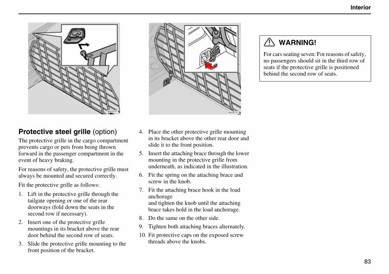
83
Interior
Protective steel grille (option)The protective grille in the cargo compartment prevents cargo or pets from being thrown forward in the passenger compartment in the event of heavy braking.
For reasons of safety, the protective grille must always be mounted and secured correctly.
Fit the protective grille as follows:
1. Lift in the protective grille through the tailgate opening or one of the rear doorways (fold down the seats in the second row if necessary).
2. Insert one of the protective grille mountings in its bracket above the rear door behind the second row of seats.
3. Slide the protective grille mounting to the front position of the bracket.
4. Place the other protective grille mounting in its bracket above the other rear door and slide it to the front position.
5. Insert the attaching brace through the lower mounting in the protective grille from underneath, as indicated in the illustration.
6. Fit the spring on the attaching brace and screw in the knob.
7. Fit the attaching brace hook in the load anchorageand tighten the knob until the attaching brace takes hold in the load anchorage.
8. Do the same on the other side.
9. Tighten both attaching braces alternately.
10. Fit protective caps on the exposed screw threads above the knobs.
WARNING!
For cars seating seven: For reasons of safety, no passengers should sit in the third row of seats if the protective grille is positioned behind the second row of seats.
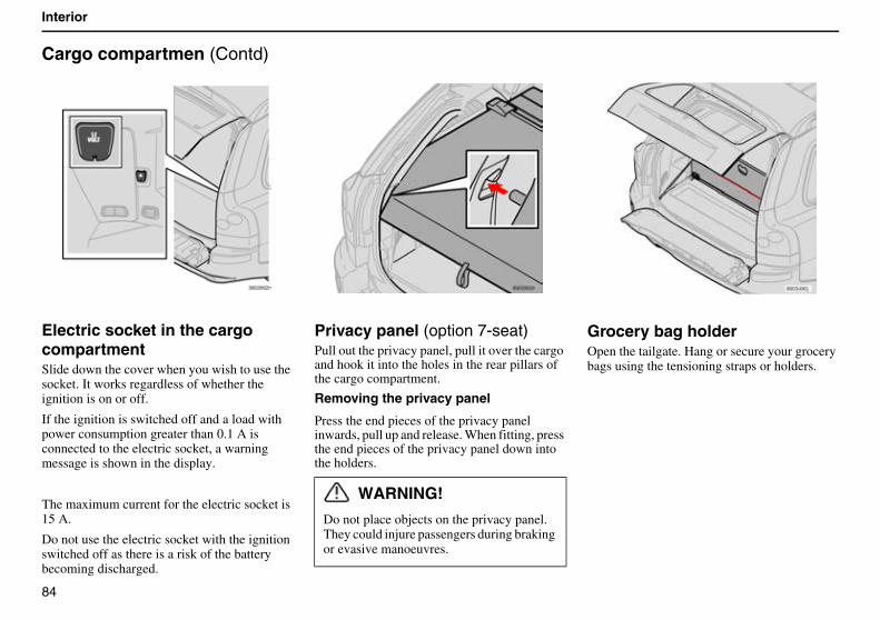
84
Interior
Cargo compartmen (Contd)
Electric socket in the cargo compartmentSlide down the cover when you wish to use the socket. It works regardless of whether the ignition is on or off.
If the ignition is switched off and a load with power consumption greater than 0.1 A is connected to the electric socket, a warning message is shown in the display.
The maximum current for the electric socket is 15 A.
Do not use the electric socket with the ignition switched off as there is a risk of the battery becoming discharged.
Privacy panel (option 7-seat)Pull out the privacy panel, pull it over the cargo and hook it into the holes in the rear pillars of the cargo compartment.
Removing the privacy panel
Press the end pieces of the privacy panel inwards, pull up and release. When fitting, press the end pieces of the privacy panel down into the holders.
Grocery bag holderOpen the tailgate. Hang or secure your grocery bags using the tensioning straps or holders.
WARNING!
Do not place objects on the privacy panel. They could injure passengers during braking or evasive manoeuvres.
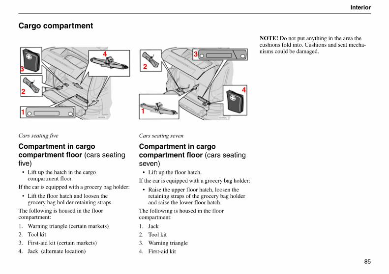
85
Interior
Cargo compartment
�������� ���� ��
Compartment in cargo compartment floor (cars seating five)
• Lift up the hatch in the cargo compartment floor.
If the car is equipped with a grocery bag holder:
• Lift the floor hatch and loosen the grocery bag hol der retaining straps.
The following is housed in the floor compartment:
1. Warning triangle (certain markets)
2. Tool kit
3. First-aid kit (certain markets)
4. Jack (alternate location)
�������� ��������
Compartment in cargo compartment floor (cars seating seven)
• Lift up the floor hatch.
If the car is equipped with a grocery bag holder:
• Raise the upper floor hatch, loosen the retaining straps of the grocery bag holder and raise the lower floor hatch.
The following is housed in the floor compartment:
1. Jack
2. Tool kit
3. Warning triangle
4. First-aid kit
������Do not put anything in the area the cushions fold into. Cushions and seat mecha-nisms could be damaged.
1
2
3
4
1
2
3
4
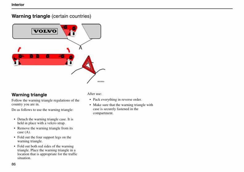
86
Interior
Warning triangle (certain countries)
Warning triangleFollow the warning triangle regulations of the country you are in.
Do as follows to use the warning triangle:
• Detach the warning triangle case. It is held in place with a velcro strap.
• Remove the warning triangle from its case (A).
• Fold out the four support legs on the warning triangle.
• Fold out both red sides of the warning triangle. Place the warning triangle in a location that is appropriate for the traffic situation.
After use:
• Pack everything in reverse order.
• Make sure that the warning triangle with case is securely fastened in the compartment.
87
Locks and alarm
Keys and remote control 88
Locking and unlocking 90
Child safety locks 93
The alarm system 95
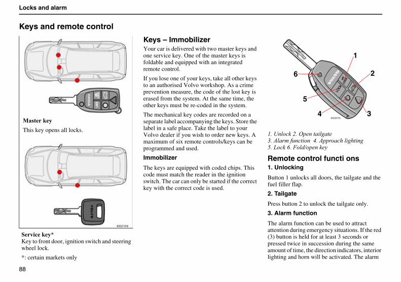
88
Locks and alarm
Keys and remote control
Keys – ImmobilizerYour car is delivered with two master keys and one service key. One of the master keys is foldable and equipped with an integrated remote control.
If you lose one of your keys, take all other keys to an authorised Volvo workshop. As a crime prevention measure, the code of the lost key is erased from the system. At the same time, the other keys must be re-coded in the system.
The mechanical key codes are recorded on a separate label accompanying the keys. Store the label in a safe place. Take the label to your Volvo dealer if you wish to order new keys. A maximum of six remote controls/keys can be programmed and used.
Immobilizer
The keys are equipped with coded chips. This code must match the reader in the ignition switch. The car can only be started if the correct key with the correct code is used.
.��=�����0��4������ �����-��(�!��'��� ����9��(������� ��� ����+�������/��&��6������� �
Remote control functi ons1. Unlocking
Button 1 unlocks all doors, the tailgate and the fuel filler flap.
2. Tailgate
Press button 2 to unlock the tailgate only.
3. Alarm function
The alarm function can be used to attract attention during emergency situations. If the red (3) button is held for at least 3 seconds or pressed twice in succession during the same amount of time, the direction indicators, interior lighting and horn will be activated. The alarm
0� ��#�
This key opens all locks.
���!�#�?�Key to front door, ignition switch and steering wheel lock.
*: certain markets only
1
2
34
5
6
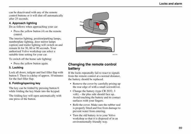
89
Locks and alarm
can be deactivated with any of the remote control buttons or it will shut off automatically after 25 seconds.
4. Approach lightingDo as follows when approaching your car:
• Press the yellow button (4) on the remote control.
The interior lighting, position/parking lamps, numberplate lighting, door mirror lamps (option) and trailer lighting will switch on and remain lit for 30, 60 or 90 seconds. Your authorised Volvo workshop can select a suitable time setting for your car.
To switch off the home safe lighting:
• Press the yellow button again.
5. Locking
Lock all doors, tailgate and fuel filler flap with button 5. There is a delay of approx. 10 minutes for the fuel filler flap.
6. Folding/opening key
The key can be folded by pressing button 6 while folding the key blade into the keypad.
The folding key will open automatically with one press of the button.
Changing the remote control batteryIf the locks repeatedly fail to react to signals from the remote control at a normal distance, the battery should be replaced.
• Remove the cover by carefully prising up the rear edge of with a small screwdriver.
• Change the battery (type CR 2032, 3 volt); – the plus side should face up. Avoid touching the battery and its contact surfaces with your fingers.
• Refit the cover. Make sure the rubber seal is properly fitted and free from damage to prevent water from entering.
• Turn the old battery in to your Volvo workshop so that it is disposed of in an environmentally friendly way.
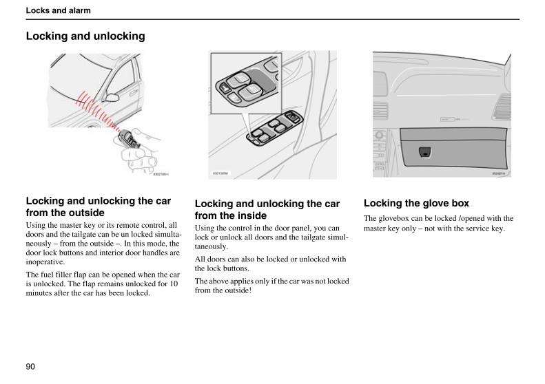
90
Locks and alarm
Locking and unlocking
Locking and unlocking the car from the outsideUsing the master key or its remote control, all doors and the tailgate can be un locked simulta-neously – from the outside –. In this mode, the door lock buttons and interior door handles are inoperative.
The fuel filler flap can be opened when the car is unlocked. The flap remains unlocked for 10 minutes after the car has been locked.
Locking and unlocking the car from the insideUsing the control in the door panel, you can lock or unlock all doors and the tailgate simul-taneously.
All doors can also be locked or unlocked with the lock buttons.
The above applies only if the car was not locked from the outside!
Locking the glove boxThe glovebox can be locked /opened with the master key only – not with the service key.
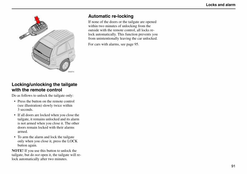
91
Locks and alarm
Locking/unlocking the tailgate with the remote controlDo as follows to unlock the tailgate only:
• Press the button on the remote control (see illustration) slowly twice within3 seconds.
• If all doors are locked when you close the tailgate, it remains unlocked and its alarm is not armed when you close it. The other doors remain locked with their alarms armed.
• To arm the alarm and lock the tailgate only when you close it, press the LOCK button again.
������If you use this button to unlock the tailgate, but do ��� open it, the tailgate will re-lock automatically after two minutes.
Automatic re-lockingIf none of the doors or the tailgate are opened within two minutes of unlocking from the outside with the remote control, all locks re-lock automatically. This function prevents you from unintentionally leaving the car unlocked.
For cars with alarms, see page 95.
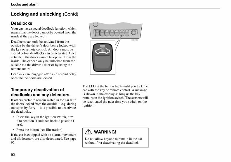
92
Locks and alarm
Locking and unlocking (Contd)
DeadlocksYour car has a special deadlock function, which means that the doors cannot be opened from the inside if they are locked.
Deadlocks can only be activated from the outside by the driver’s door being locked with the key or remote control. All doors must be closed before deadlocks can be activated. Once activated, the doors cannot be opened from the inside. The car can only be unlocked from the outside via the driver’s door or by using the remote control.
Deadlocks are engaged after a 25 second delay once the the doors are locked.
Temporary deactivation of deadlocks and any detectors.If others prefer to remain seated in the car with the doors locked from the outside – e.g. during transport by ferry, – it is possible to deactivate the deadlocks.
• Insert the key in the ignition switch, turn it to position II and then back to position I or 0.
• Press the button (see illustration).
If the car is equipped with an alarm, movement and tilt detectors are also deactivated. See page 96.
The LED in the button lights until you lock the car with the key or remote control. A message is shown in the display as long as the key remains in the ignition switch. The sensors will be reactivated the next time you switch on the ignition.
WARNING!
Do not allow anyone to remain in the car without first deactivating the deadlock.
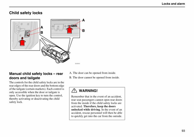
93
Locks and alarm
Child safety locks
Manual child safety locks – rear doors and tailgateThe controls for the child safety locks are in the rear edges of the rear doors and the bottom edge of the tailgate (certain markets). Each control is only accessible when the door or tailgate is open. Use the ignition key to turn the control, thereby activating or deactivating the child safety lock.
A. The door can be opened from inside.
B. The door cannot be opened from inside.
WARNING!
Remember that in the event of an accident, rear seat passengers cannot open rear doors from the inside if the child safety locks are activated. �� �,�#�������� �����!#�������������. In the event of an accident, rescue personnel will then be able to quickly get into the car from the outside.
AB
A
B
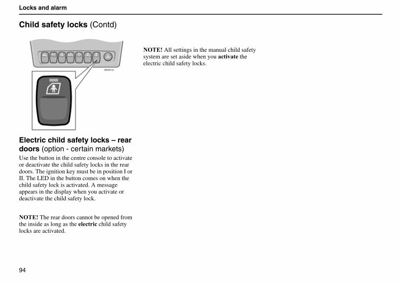
94
Locks and alarm
Child safety locks (Contd)
Electric child safety locks – rear doors (option - certain markets)Use the button in the centre console to activate or deactivate the child safety locks in the rear doors. The ignition key must be in position I or II. The LED in the button comes on when the child safety lock is activated. A message appears in the display when you activate or deactivate the child safety lock.
������The rear doors cannot be opened from the inside as long as the �!��! child safety locks are activated.
������All settings in the manual child safety system are set aside when you �!����� the electric child safety locks.
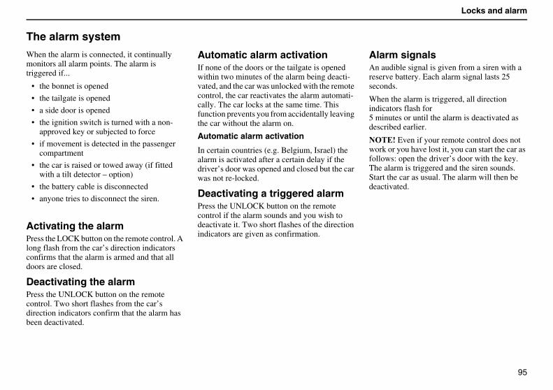
95
Locks and alarm
The alarm system
When the alarm is connected, it continually monitors all alarm points. The alarm is triggered if...
• the bonnet is opened
• the tailgate is opened
• a side door is opened
• the ignition switch is turned with a non-approved key or subjected to force
• if movement is detected in the passenger compartment
• the car is raised or towed away (if fitted with a tilt detector – option)
• the battery cable is disconnected
• anyone tries to disconnect the siren.
Activating the alarmPress the LOCK button on the remote control. A long flash from the car’s direction indicators confirms that the alarm is armed and that all doors are closed.
Deactivating the alarmPress the UNLOCK button on the remote control. Two short flashes from the car’s direction indicators confirm that the alarm has been deactivated.
Automatic alarm activationIf none of the doors or the tailgate is opened within two minutes of the alarm being deacti-vated, and the car was unlocked with the remote control, the car reactivates the alarm automati-cally. The car locks at the same time. This function prevents you from accidentally leaving the car without the alarm on.
Automatic alarm activation
In certain countries (e.g. Belgium, Israel) the alarm is activated after a certain delay if the driver’s door was opened and closed but the car was not re-locked.
Deactivating a triggered alarmPress the UNLOCK button on the remote control if the alarm sounds and you wish to deactivate it. Two short flashes of the direction indicators are given as confirmation.
Alarm signalsAn audible signal is given from a siren with a reserve battery. Each alarm signal lasts 25 seconds.
When the alarm is triggered, all direction indicators flash for5 minutes or until the alarm is deactivated as described earlier.
������Even if your remote control does not work or you have lost it, you can start the car as follows: open the driver’s door with the key. The alarm is triggered and the siren sounds. Start the car as usual. The alarm will then be deactivated.
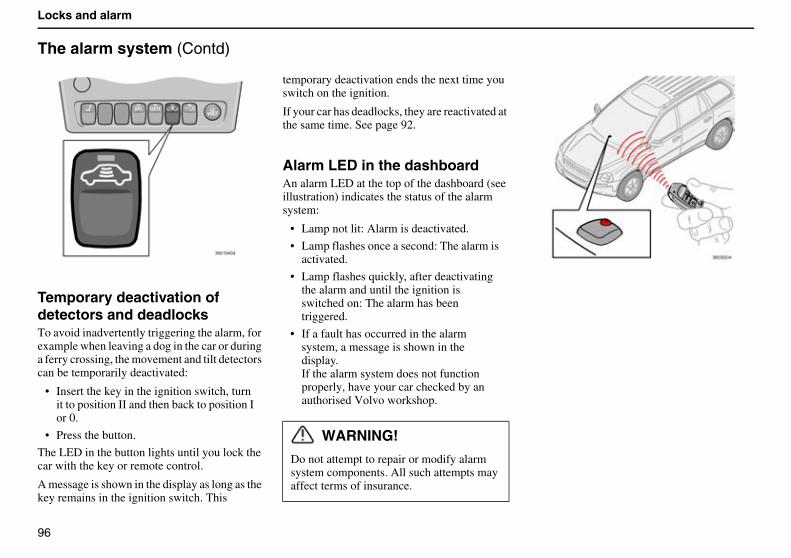
96
Locks and alarm
The alarm system (Contd)
Temporary deactivation of detectors and deadlocksTo avoid inadvertently triggering the alarm, for example when leaving a dog in the car or during a ferry crossing, the movement and tilt detectors can be temporarily deactivated:
• Insert the key in the ignition switch, turn it to position II and then back to position I or 0.
• Press the button.
The LED in the button lights until you lock the car with the key or remote control.
A message is shown in the display as long as the key remains in the ignition switch. This
temporary deactivation ends the next time you switch on the ignition.
If your car has deadlocks, they are reactivated at the same time. See page 92.
Alarm LED in the dashboardAn alarm LED at the top of the dashboard (see illustration) indicates the status of the alarm system:
• Lamp not lit: Alarm is deactivated.
• Lamp flashes once a second: The alarm is activated.
• Lamp flashes quickly, after deactivating the alarm and until the ignition is switched on: The alarm has been triggered.
• If a fault has occurred in the alarm system, a message is shown in the display.If the alarm system does not function properly, have your car checked by an authorised Volvo workshop.
WARNING!
Do not attempt to repair or modify alarm system components. All such attempts may affect terms of insurance.
97
Starting and driving
General 98
Refuelling 100
Starting the car 101
Manual gearbox 102
Automatic gearbox AW5 and GM with Geartronic 103
All-wheel drive 105
Brake system 106
Stability system 108
Parking assistance system (option) 110
Towing 111
Jump starting 112
Driving with a trailer 113
Towing bracket (option) 115
Load on the roof 119
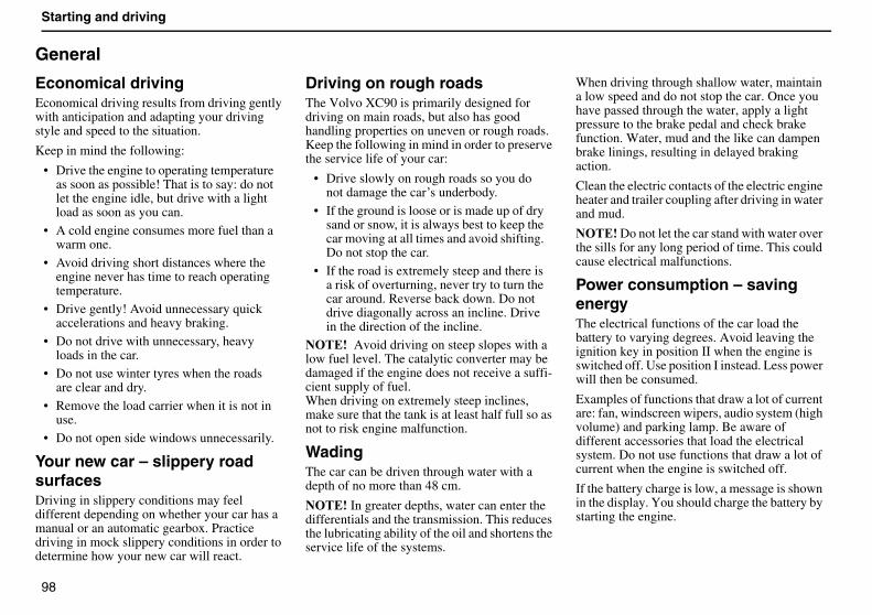
98
Starting and driving
General
Economical drivingEconomical driving results from driving gently with anticipation and adapting your driving style and speed to the situation.
Keep in mind the following:
• Drive the engine to operating temperature as soon as possible! That is to say: do not let the engine idle, but drive with a light load as soon as you can.
• A cold engine consumes more fuel than a warm one.
• Avoid driving short distances where the engine never has time to reach operating temperature.
• Drive gently! Avoid unnecessary quick accelerations and heavy braking.
• Do not drive with unnecessary, heavy loads in the car.
• Do not use winter tyres when the roads are clear and dry.
• Remove the load carrier when it is not in use.
• Do not open side windows unnecessarily.
Your new car – slippery road surfacesDriving in slippery conditions may feel different depending on whether your car has a manual or an automatic gearbox. Practice driving in mock slippery conditions in order to determine how your new car will react.
Driving on rough roadsThe Volvo XC90 is primarily designed for driving on main roads, but also has good handling properties on uneven or rough roads. Keep the following in mind in order to preserve the service life of your car:
• Drive slowly on rough roads so you do not damage the car’s underbody.
• If the ground is loose or is made up of dry sand or snow, it is always best to keep the car moving at all times and avoid shifting. Do not stop the car.
• If the road is extremely steep and there is a risk of overturning, never try to turn the car around. Reverse back down. Do not drive diagonally across an incline. Drive in the direction of the incline.
������ Avoid driving on steep slopes with a low fuel level. The catalytic converter may be damaged if the engine does not receive a suffi-cient supply of fuel.When driving on extremely steep inclines, make sure that the tank is at least half full so as not to risk engine malfunction.
WadingThe car can be driven through water with a depth of no more than 48 cm.
������In greater depths, water can enter the differentials and the transmission. This reduces the lubricating ability of the oil and shortens the service life of the systems.
When driving through shallow water, maintain a low speed and do not stop the car. Once you have passed through the water, apply a light pressure to the brake pedal and check brake function. Water, mud and the like can dampen brake linings, resulting in delayed braking action.
Clean the electric contacts of the electric engine heater and trailer coupling after driving in water and mud.
������Do not let the car stand with water over the sills for any long period of time. This could cause electrical malfunctions.
Power consumption – saving energyThe electrical functions of the car load the battery to varying degrees. Avoid leaving the ignition key in position II when the engine is switched off. Use position I instead. Less power will then be consumed.
Examples of functions that draw a lot of current are: fan, windscreen wipers, audio system (high volume) and parking lamp. Be aware of different accessories that load the electrical system. Do not use functions that draw a lot of current when the engine is switched off.
If the battery charge is low, a message is shown in the display. You should charge the battery by starting the engine.
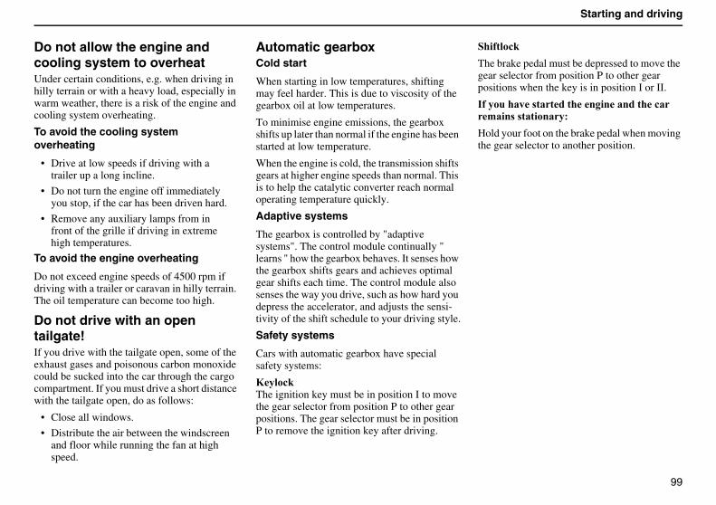
99
Starting and driving
Do not allow the engine andcooling system to overheatUnder certain conditions, e.g. when driving in hilly terrain or with a heavy load, especially in warm weather, there is a risk of the engine and cooling system overheating.
To avoid the cooling system overheating
• Drive at low speeds if driving with a trailer up a long incline.
• Do not turn the engine off immediately you stop, if the car has been driven hard.
• Remove any auxiliary lamps from in front of the grille if driving in extreme high temperatures.
To avoid the engine overheating
Do not exceed engine speeds of 4500 rpm if driving with a trailer or caravan in hilly terrain. The oil temperature can become too high.
Do not drive with an open tailgate!If you drive with the tailgate open, some of the exhaust gases and poisonous carbon monoxide could be sucked into the car through the cargo compartment. If you must drive a short distance with the tailgate open, do as follows:
• Close all windows.
• Distribute the air between the windscreen and floor while running the fan at high speed.
Automatic gearboxCold start
When starting in low temperatures, shifting may feel harder. This is due to viscosity of the gearbox oil at low temperatures.
To minimise engine emissions, the gearbox shifts up later than normal if the engine has been started at low temperature.
When the engine is cold, the transmission shifts gears at higher engine speeds than normal. This is to help the catalytic converter reach normal operating temperature quickly.
Adaptive systems
The gearbox is controlled by "adaptive systems". The control module continually " learns " how the gearbox behaves. It senses how the gearbox shifts gears and achieves optimal gear shifts each time. The control module also senses the way you drive, such as how hard you depress the accelerator, and adjusts the sensi-tivity of the shift schedule to your driving style.
Safety systems
Cars with automatic gearbox have special safety systems:
9���!#��The ignition key must be in position I to move the gear selector from position P to other gear positions. The gear selector must be in position P to remove the ignition key after driving.
��� ���!#��
The brake pedal must be depressed to move the gear selector from position P to other gear positions when the key is in position I or II.
� ��������� ��������������������!��'��� � ���������
Hold your foot on the brake pedal when moving the gear selector to another position.
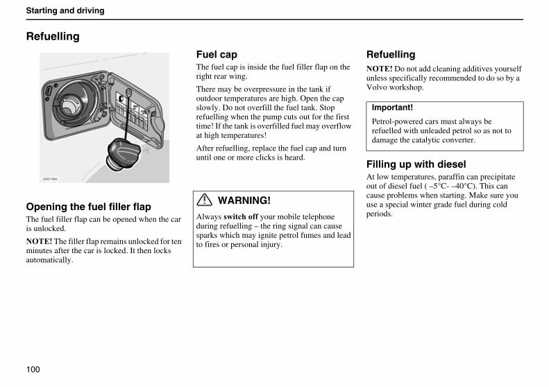
100
Starting and driving
Refuelling
Opening the fuel filler flapThe fuel filler flap can be opened when the car is unlocked.
������The filler flap remains unlocked for ten minutes after the car is locked. It then locks automatically.
Fuel capThe fuel cap is inside the fuel filler flap on the right rear wing.
There may be overpressure in the tank if outdoor temperatures are high. Open the cap slowly. Do not overfill the fuel tank. Stop refuelling when the pump cuts out for the first time! If the tank is overfilled fuel may overflow at high temperatures!
After refuelling, replace the fuel cap and turn until one or more clicks is heard.
WARNING!
Always ���!��� your mobile telephone during refuelling – the ring signal can cause sparks which may ignite petrol fumes and lead to fires or personal injury.
Refuelling������Do not add cleaning additives yourself unless specifically recommended to do so by a Volvo workshop.
Filling up with dieselAt low temperatures, paraffin can precipitate out of diesel fuel ( –5°C- –40°C). This can cause problems when starting. Make sure you use a special winter grade fuel during cold periods.
Important!
Petrol-powered cars must always be refuelled with unleaded petrol so as not to damage the catalytic converter.
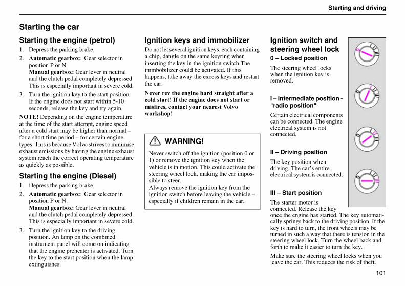
101
Starting and driving
Starting the car
Starting the engine (petrol)1. Depress the parking brake.
2. ����'���!�����6�� Gear selector in position P or N.0����������6��Gear lever in neutral and the clutch pedal completely depressed. This is especially important in severe cold.
3. Turn the ignition key to the start position. If the engine does not start within 5-10 seconds, release the key and try again.
������Depending on the engine temperature at the time of the start attempt, engine speed after a cold start may be higher than normal – for a short time period – for certain engine types. This is because Volvo strives to minimise exhaust emissions by having the engine exhaust system reach the correct operating temperature as quickly as possible.
Starting the engine (Diesel)1. Depress the parking brake.
2. ����'���!�����6�� Gear selector in position P or N.0����������6��Gear lever in neutral and the clutch pedal completely depressed. This is especially important in severe cold.
3. Turn the ignition key to the driving position. An lamp on the combined instrument panel will come on indicating that the engine preheater is activated. Turn the key to the start position when the lamp extinguishes.
Ignition keys and immobilizerDo not let several ignition keys, each containing a chip, dangle on the same keyring when inserting the key in the ignition switch.The immbobilizer could be activated. If this happens, take away the excess keys and restart the car.
����������������� �������� ����!���� ������ ����������� ����� ������'� � ,�!����!�������� ��:�������# ����
Ignition switch and steering wheel lock0 – Locked position
The steering wheel locks when the ignition key is removed.
I – Intermediate position - "radio position"
Certain electrical components can be connected. The engine electrical system is not connected.
II – Driving position
The key position when driving. The car’s entire electrical system is connected.
III – Start position
The starter motor is connected. Release the key once the engine has started. The key automati-cally springs back to the driving position. If the key is hard to turn, the front wheels may be turned in such a way that there is tension in the steering wheel lock. Turn the wheel back and forth to make it easier to turn the key.
Make sure the steering wheel locks when you leave the car. This reduces the risk of theft.
WARNING!
Never switch off the ignition (position 0 or 1) or remove the ignition key when the vehicle is in motion. This could activate the steering wheel lock, making the car impos-sible to steer.Always remove the ignition key from the ignition switch before leaving the vehicle – especially if children remain in the car.
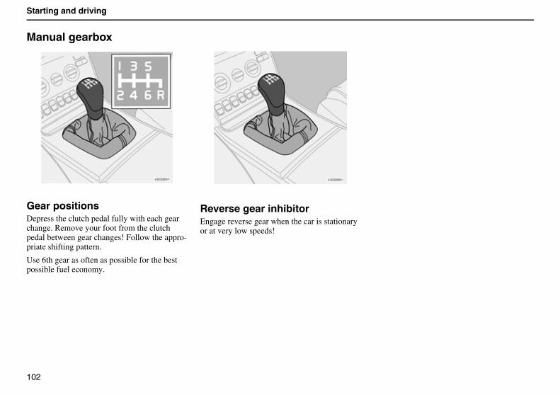
102
Starting and driving
Manual gearbox
Gear positionsDepress the clutch pedal fully with each gear change. Remove your foot from the clutch pedal between gear changes! Follow the appro-priate shifting pattern.
Use 6th gear as often as possible for the best possible fuel economy.
Reverse gear inhibitorEngage reverse gear when the car is stationary or at very low speeds!
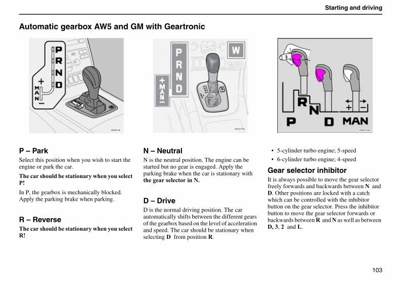
103
Starting and driving
Automatic gearbox AW5 and GM with Geartronic
P – ParkSelect this position when you wish to start the engine or park the car.
���!�� �������� ����������������� �!����
In P, the gearbox is mechanically blocked. Apply the parking brake when parking.
R – Reverse���!�� �������� ����������������� �!��%�
N – NeutralN is the neutral position. The engine can be started but no gear is engaged. Apply the parking brake when the car is stationary with ������ �!�������$�
D – DriveD is the normal driving position. The car automatically shifts between the different gears of the gearbox based on the level of acceleration and speed. The car should be stationary when selecting �� from position %.
• 5-cylinder turbo engine; 5-speed
• 6-cylinder turbo engine; 4-speed
Gear selector inhibitorIt is always possible to move the gear selector freely forwards and backwards between �� and �. Other positions are locked with a catch which can be controlled with the inhibitor button on the gear selector. Press the inhibitor button to move the gear selector forwards or backwards between %� and � as well as between �, *, )� and &.
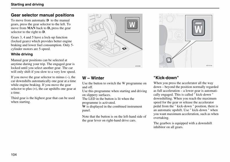
104
Starting and driving
Gear selector manual positionsTo move from automatic �� to the manual gears, press the gear selector to the left. To move from 0�� back to �, press the gear selector to the right to �.
Gears 3, 4 and 5 have a lock-up function (locked gears) which provides better engine braking and lower fuel consumption. Only 5-cylinder motors are 5-speed.
While driving
Manual gear positions can be selected at anytime during your trip. The engaged gear is locked until you select another gear. The car will only shift if you slow to a very low speed.
If you move the gear selector to minus (–), the car downshifts automatically one gear at a time while engine braking. If you move the gear selector to plus (+), the car upshifts one gear at a time.
Third gear is the highest gear that can be used when starting.
W – Winter Use the button to switch the W programme on and off.Use this programme when starting and driving on slippery surfaces.The LED in the button is lit when the programme is activated.3 is displayed in the combined instrument panel.
Note that the button is on the left-hand side of the gear lever on right-hand drive cars.
"Kick-down" When you press the accelerator all the way down – beyond the position normally regarded as full acceleration – a lower gear is automati-cally engaged. This is called " kick-down " downshifting. When you reach the maximum speed for the gear or release the accelerator pedal from the " kick-down " position, there is an automatic upshift. Use " kick-down " when you want maximum acceleration, such as when overtaking.
The gearbox is equipped with a downshift inhibitor on all gears.
105
Starting and driving
All-wheel drive
AWD – All-Wheel DriveThe all-wheel drive system in your Volvo is constantly engaged and meets very high technical requirements. Used correctly, all-wheel drive provides the driver better control on various road surfaces than conventional rear-wheel drive.
All-wheel drive means that all four road wheels are driven at the same time. Power is automati-cally distributed between front and rear wheels. An electronically controlled clutch system distributes the power to the pair ofwheels that grips best. This provides the best traction and prevents wheel spin.
Under normal driving conditions, the majority of power is transmitted to the front wheels.
The greater traction improves driving safety in rain, snow and icy conditions.
Tyre sizes and pressuresVolvo recommends that you only drive with tyres of the same brand, size, specifications, load designation, and speed designation. Tyre sizes and pressures are specified in the table on the inside of the fuel filler flap and in the Owner’s Manual. See page 125.
Snow chainsSnow chains may only be fitted to the front wheels on all-wheel drive cars.
������To avoid damaging wheel housing components, only use chains specially designed and adapted for Volvo XC90.
106
Starting and driving
Brake system
If a brake circuit failsThe brake pedal can be depressed further and feels softer than usual. It also requires more pressure on
the pedal to achieve a normal braking effect.
The brake servo only works when the engine is running.
If the car is rolling or being towed with the engine switched off, you must apply approxi-mately 5 times more pressure on the brake pedal than when the engine is running. �����#������ � �������������$
������When braking with a switched off engine, depress the brake pedal one time hard and distinct – not repeatedly.
Moisture on the brake discs and brake lining alter braking characteristics!
Brake components become wet when the car is driven in heavy rain or through pools of water or when the car is washed. This alters brake pad friction characteristics so that there is a delay before braking effect is noticed. Depress the brake pedal lightly from time to time when driving long distances in rain or slush and before parking your car in such conditions. This helps the brake lining warm up and dry out. You should also do this when driving after washing the car and when starting in damp or cold weather conditions.
If the brakes are heavily loaded
When driving in the Alps or other roads with similar characteristics, the car’s brakes are heavily loaded even if you are not pressing the pedal especially hard. Because speed is often low, the brakes are not cooled as effectively as when driving on flat roads.
In order to prevent abnormal brake stress, shift down and use the same gear uphill and downhill instead of using the brake (manual gearbox). Thus, engine braking works more efficiently and brake use will be necessary during short periods only.
Keep in mind that the brakes are even more heavily loaded when driving with a trailer.
107
Starting and driving
Antilock braking system (ABS)The ABS system (Anti-lock Brake System) is designed so
that the wheels do not lock when braking. This retains the best possible steering response when braking. Thisimproves your ability to swerve to avoid obstacles. The ABS system does not increase your total braking capacity. However, as the driver you have increased ability to steer and thus better control over the car, which in turn increases safety.
After the engine has started and reached a speed of about 20 km/h, a short self-test can be both heard and felt. When the ABS system functions, you can hear and feel pulses in the brake pedal. This is completely normal.
������You must depress the brake pedal fully to take maximum advantage of the ABS system. Do not release the pedal when you hear and feel the ABS pulses. Practice braking with the ABS system in a untrafficked area.
����8�� �'��������� ����� ��� ��������!�� ���������$$$
• for approximately two seconds when you start the car to test the system.
• if the ABS system has shut down due to a fault.
Electronic Brakeforce Distribution (EBD)The Electronic Brakeforce Distribution system (EBD) is an integrated part of the ABS system. The EBD system controls the brake force to the rear wheels so that the best possible braking force is always available. Pulses will be heard and felt through the brake pedal when the system regulates brake force.
If the 8%�9�� and �8� warning
symbols light at the same time, there is a risk that the rear end will have a tendency to slide during heavy braking. If the brake fluid level is normal, carefully drive the car to the nearest authorised Volvo workshop to have the brake system checked.
108
Starting and driving
Stability system
DSTC – Dynamic Stability and Traction Control
The Dynamic Stability and Traction Control system (DSTC) comprises several different functions:
• ��!�����"������;�"<
The Traction Control function transfers power from the spinning drive wheel to the drive wheel which has grip by braking the spinning drive wheel. To increase forward traction in this situation, you may need to depress the accelerator more than usual. A pulsing sound is heard when Traction Control is working. This is completely normal. The TC function is most active at low speeds. It cannot be switched off.
• ����������"������;�"<
The Stability Control function is designed to prevent the drive wheels from slipping during acceleration by lowering engine torque. This improves navigation and road safety on slippery surfaces. Under certain conditions, such as when driving with snow chains or in deep snow or sand, it may be beneficial to switch off
the SC function to increase traction. This is done using the DSTC button.
• �!����A���"������;�A"<
The Active Yaw Control function automatically brakes one or more of the wheels to stabilise the car in the event of a skid. If you were to depress the brake pedal in this situation, it would feel more rigid than usual and a pulsing sound would be heard. For reasons of safety, the AYC function is always active and cannot be switched off.
• %��������������"������;%�"<
The Roll Stability Control function automatically brakes one or more wheels. This stabilises the car laterally so as to minimise the risk of overturning due to a skid or the like. If you were to depress the brake pedal in this situation, it would feel more rigid and a pulsing sound would be heard. For reasons of safety, the RSC function is always active and cannot be switched off.
DSTC button
The DSTC button in the centre console is used to reduce or reactivate the DSTC system.
Reducing the system means that the Stability Control (SC) and Active Yaw Control (AYC) functions are reduced. Other functions are not affected.
When the LED in the button is lit, the DSTC system is activated (assuming there is no fault).
������For reasons of safety, the button must be depressed for at least one half second to reduce the DSTC system function.
������The LED in the button is extinguished and "DSTC SPIN CONTROL OFF" is shown in the display.
The DSTC system is automatically reactivated each time the engine is started.
The warning symbol flashes when...
• The SC function works to keep the car’s drive wheels from slipping.
• The TC function works to improve the car’s traction.
• The AYC function works to keep the car from skidding.
• The RSC function works to prevent the car from overturning.
109
Starting and driving
The warning symbol lights and goes out again after 2 seconds when...
• the car is started. (The lamp lights for a system check.)
The LED in the button goes out and the text "DSTC SPIN CONTROL OFF" is shown in the display when...
• The SC function of the DSTC system has been reduced with the DSTC button.
The warning symbol shines with a steady amber glow and the text "TRACTION CONTROL TEMPORARILY OFF" is shown in the display when...
• the TC function of the brake system has been temporarily reduced due to high brake temperature. The TC function is reactivated automatically when the brake temperature returns to normal levels.
The warning symbol shines with a steady amber glow and the text "ANTI-SKID SERVICE REQUIRED" is shown in the display when...
• The DSTC system has shut down due to a fault.
Emergency Brake Assistance (EBA)The (EBA) function is integrated in the DSTC system and is designed to provide immediate maximum braking force whenever rapid brake application is necessary. The system detects the need for heavier braking by registering how quickly the brake pedal is applied.
The EBA function is active at all speeds. For reasons of safety, it cannot be switched off.
������When the EBA function is activated, the brake pedal sinks while maximum braking force is applied. Continue braking without releasing the brake pedal. The EBA function disengages when the pressure on the brake pedal is released.
WARNING!
Under normal driving conditions, the DSTC system improves the car’s road safety, but this should not be taken as a reason to increase speed. Always follow the usual precautions for safe cornering and driving on slippery surfaces.
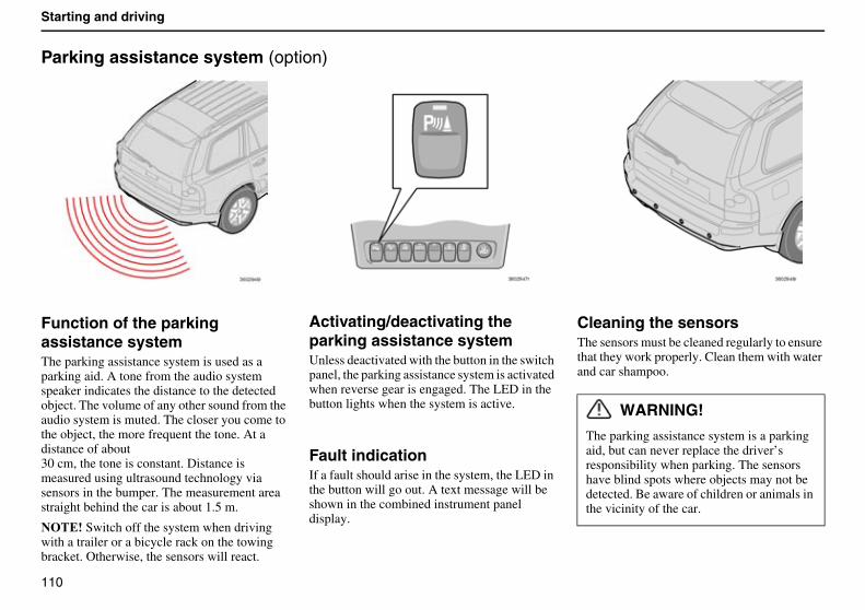
110
Starting and driving
Parking assistance system (option)
Function of the parking assistance systemThe parking assistance system is used as a parking aid. A tone from the audio system speaker indicates the distance to the detected object. The volume of any other sound from the audio system is muted. The closer you come to the object, the more frequent the tone. At a distance of about30 cm, the tone is constant. Distance is measured using ultrasound technology via sensors in the bumper. The measurement area straight behind the car is about 1.5 m.
������Switch off the system when driving with a trailer or a bicycle rack on the towing bracket. Otherwise, the sensors will react.
Activating/deactivating the parking assistance systemUnless deactivated with the button in the switch panel, the parking assistance system is activated when reverse gear is engaged. The LED in the button lights when the system is active.
Fault indicationIf a fault should arise in the system, the LED in the button will go out. A text message will be shown in the combined instrument panel display.
Cleaning the sensorsThe sensors must be cleaned regularly to ensure that they work properly. Clean them with water and car shampoo.
WARNING!
The parking assistance system is a parking aid, but can never replace the driver’s responsibility when parking. The sensors have blind spots where objects may not be detected. Be aware of children or animals in the vicinity of the car.
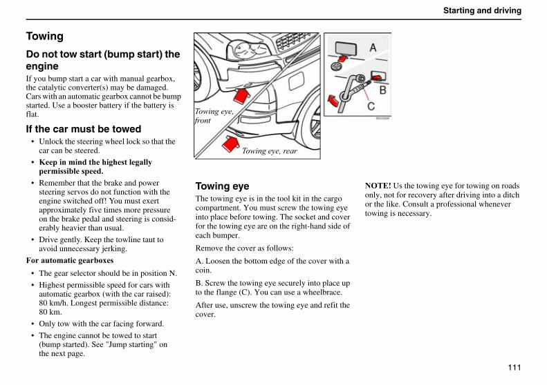
111
Starting and driving
Towing
Do not tow start (bump start) the engineIf you bump start a car with manual gearbox, the catalytic converter(s) may be damaged. Cars with an automatic gearbox cannot be bump started. Use a booster battery if the battery is flat.
If the car must be towed• Unlock the steering wheel lock so that the
car can be steered.
B 9�����'����������� ����������'� ���� ��$
• Remember that the brake and power steering servos do not function with the engine switched off! You must exert approximately five times more pressure on the brake pedal and steering is consid-erably heavier than usual.
• Drive gently. Keep the towline taut to avoid unnecessary jerking.
7������'���!�����6
• The gear selector should be in position N.
• Highest permissible speed for cars with automatic gearbox (with the car raised): 80 km/h. Longest permissible distance: 80 km.
• Only tow with the car facing forward.
• The engine cannot be towed to start (bump started). See "Jump starting" on the next page.
Towing eyeThe towing eye is in the tool kit in the cargo compartment. You must screw the towing eye into place before towing. The socket and cover for the towing eye are on the right-hand side of each bumper.
Remove the cover as follows:
A. Loosen the bottom edge of the cover with a coin.
B. Screw the towing eye securely into place up to the flange (C). You can use a wheelbrace.
After use, unscrew the towing eye and refit the cover.
������Us the towing eye for towing on roads only, not for recovery after driving into a ditch or the like. Consult a professional whenever towing is necessary.
$�� ���� �"���
$�� ���� �"����
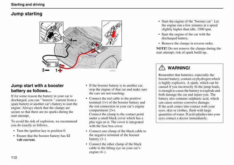
112
Starting and driving
Jump starting
Jump start with a booster battery as follows...If for some reason the battery in your car is discharged, you can " borrow " current from a spare battery or another car’s battery to start the engine. Always check that the clamps are secure so that there are no sparks during the start attempt.
To avoid the risk of explosion, we recommend you do exactly as follows.
• Turn the ignition key to position 0.
• Ensure that the booster battery has ()������!���$
• If the booster battery is in another car, stop the engine of that car and make sure the cars are not touching.
• Connect the red cable to the positive terminal (1+) of the booster battery and the red connection in your car’s engine compartment (2+).Connect the clamp to the contact point under a small black cover which has a plus sign on it. The cover is integrated with the fuse box cover.
• Connect one clamp of the black cable to the negative terminal of the booster battery (3–).
• Connect the other clamp of the black cable to the lifting eye on your car’s engine (4–).
• Start the engine of the "booster car". Let the engine run a few minutes at a speed slightly higher than idle, 1500 rpm.
• Start the engine of the car with the discharged battery.
• Remove the clamps in reverse order.
������Do not remove the clamps during the start attempt; risk of spark build-up.
WARNING!
Remember that batteries, especially the booster battery, contain oxyhydrogen which is highly explosive. A spark, which can be caused if you incorrectly fit the jump leads, is enough to cause the battery to explode and both damage the car and injure you. The battery also contains sulphuric acid, which can cause serious corrosive damage.If the acid comes into contact with your eyes, skin or clothes, flush with large quantities of water. If acid splashes into your eyes contact a doctor immediately.
3 1
24
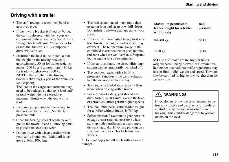
113
Starting and driving
Driving with a trailer
• The car’s towing bracket must be of an approved type.
• If the towing bracket is fitted by Volvo, the car is delivered with the necessary equipment to drive with a trailer. If retro-fitting, check with your Volvo dealer to ensure that the car is fully equipped to drive with a trailer.
• Distribute the load in the trailer so that the weight on the towing bracket is approximately 50 kg for trailer weights under 1200 kg and approximately 90 kg for trailer weights over 1200 kg. ������The weight on the towing bracket (50/90 kg) is part of the vehicle's load capacity.The load in the cargo compartment may need to be reduced so that axle load and/or total weight do not exceed the maximum limits when driving with a trailer.
• Increase tyre pressure to correspond to the pressure for full load. See the tyre pressure table!
• Clean the towing bracket regularly and grease the towball* and all moving parts to prevent unnecessary wear.
• Do not drive with a heavy trailer when your car is brand new! Wait until it hasgone at least 1000 km.
• The brakes are loaded much more than usual on long and steep downhill slopes. Downshift to a lower gear and adjust your speed.
• If the car is driven with a heavy load in a hot climate, the engine and gearbox may overheat. The temperature gauge in the combined instrument panel goes into the red zone when the car overheats. Stop and let the engine idle a few minutes.
• If the car overheats, the air conditioning system can be temporarily switched off.
• The gearbox reacts with a built-in protection function if the car overheats. See the message in the display!
• The engine is loaded more heavily than usual when driving with a trailer.
• For reasons of safety, you should not drive faster than 80 km/h, even if the laws of certain countries permit higher speeds.
• The maximum permissible trailer weight for a trailer without brakes is 750 kg.
• Select position P (automatic gear box) or engage a gear (manual gearbox) when parking with a trailer and always apply the parking brake. If you are parking on a steep incline, place chocks behind the wheels.
* Does not apply to ball hitch with vibration damper.
������The above are the highest trailer weights permitted by Volvo Car Corporation. Remember that national traffic regulations may further limit trailer weight and speed. Towbars may be certified for higher tow weights than the car may tow.
0�6�'�'��'� ��������������� ����������������#
8����� �
0-1200 kg 50 kg
2250 kg 90 kg
WARNING!
If you do not follow the given recommenda-tions, the trailer and car may be difficult to control during evasive manoeuvres and braking. This could be dangerous to you and others on the road.
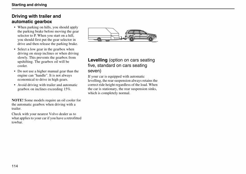
114
Starting and driving
Driving with trailer and automatic gearbox
• When parking on hills, you should apply the parking brake before moving the gear selector to P. When you start on a hill, you should first put the gear selector in drive and then release the parking brake.
• Select a low gear in the gearbox when driving on steep inclines or when driving slowly. This prevents the gearbox from upshifting. The gearbox oil will be cooler.
• Do not use a higher manual gear than the engine can "handle". It is not always economical to drive in high gears.
• Avoid driving with trailer and automatic gearbox on inclines exceeding 15%.
������Some models require an oil cooler for the automatic gearbox when driving with a trailer.
Check with your nearest Volvo dealer as to what applies to your car if you have a retrofitted towbar.
Levelling (option on cars seating five, standard on cars seating seven)If your car is equipped with automaticlevelling, the rear suspension always retains the correct ride height regardless of the load. When the car is stationary, the rear suspension sinks, which is completely normal.
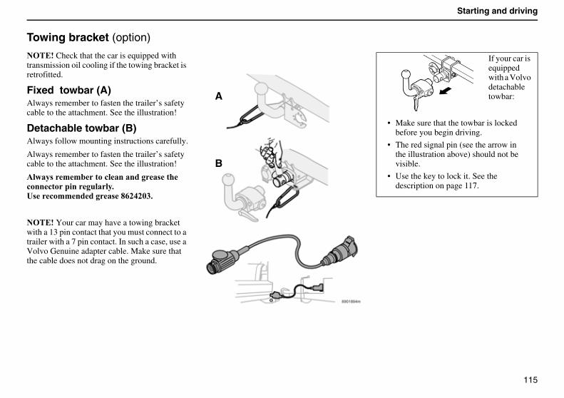
115
Starting and driving
Towing bracket (option)
������Check that the car is equipped with transmission oil cooling if the towing bracket is retrofitted.
Fixed towbar (A)Always remember to fasten the trailer’s safety cable to the attachment. See the illustration!
Detachable towbar (B)Always follow mounting instructions carefully.
Always remember to fasten the trailer’s safety cable to the attachment. See the illustration!
����� �''�����!���������� ����!���!�������������$C �!�''������ �2.)+)5*$
������Your car may have a towing bracket with a 13 pin contact that you must connect to a trailer with a 7 pin contact. In such a case, use a Volvo Genuine adapter cable. Make sure that the cable does not drag on the ground.
A
B
If your car is equipped with a Volvo detachable towbar:
• Make sure that the towbar is locked before you begin driving.
• The red signal pin (see the arrow in the illustration above) should not be visible.
• Use the key to lock it. See the description on page 117.
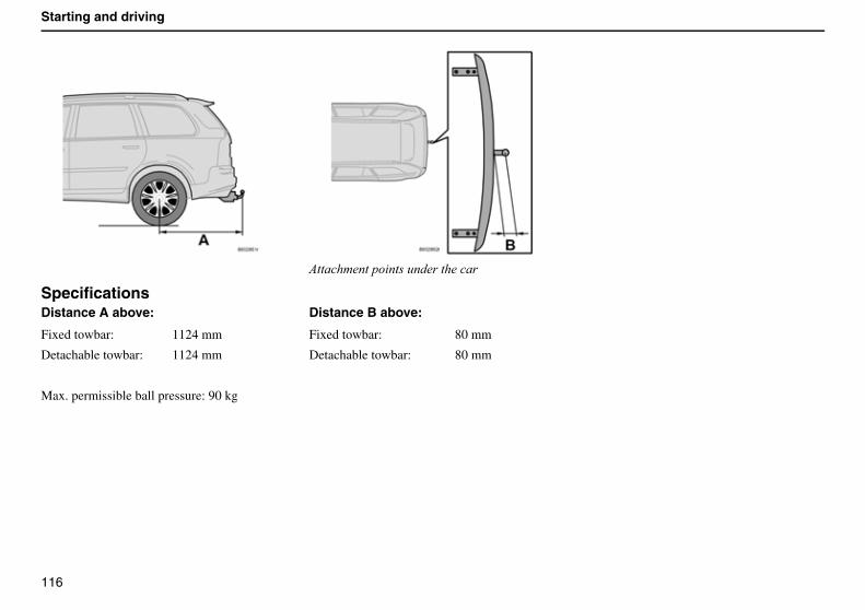
116
Starting and driving
SpecificationsDistance A above:
Fixed towbar: 1124 mm
Detachable towbar: 1124 mm
Max. permissible ball pressure: 90 kg
(�����!������ ����'����������
Distance B above:
Fixed towbar: 80 mm
Detachable towbar: 80 mm
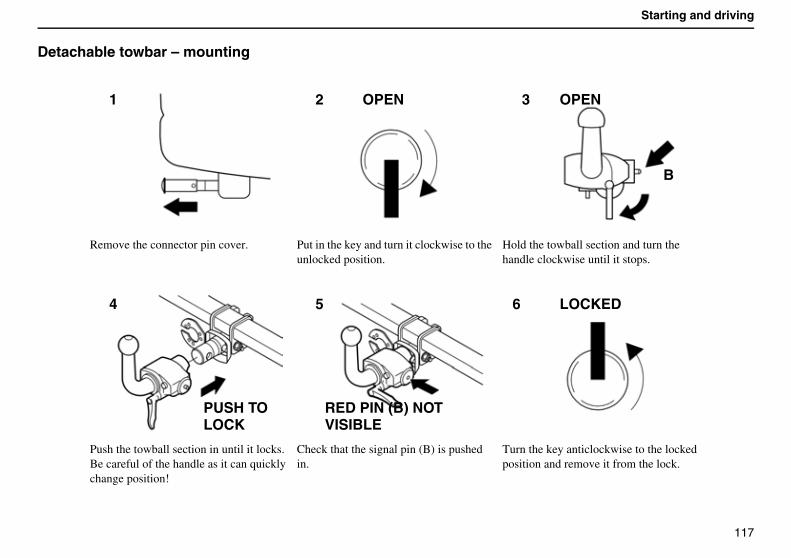
117
Starting and driving
Detachable towbar – mounting�
Remove the connector pin cover. Put in the key and turn it clockwise to the unlocked position.
Hold the towball section and turn the handle clockwise until it stops.
Push the towball section in until it locks. Be careful of the handle as it can quickly change position!
Check that the signal pin (B) is pushed in.
Turn the key anticlockwise to the locked position and remove it from the lock.
1 2 OPEN OPEN
B
3
4
PUSH TOLOCK
5
RED PIN (B) NOTVISIBLE
6 LOCKED
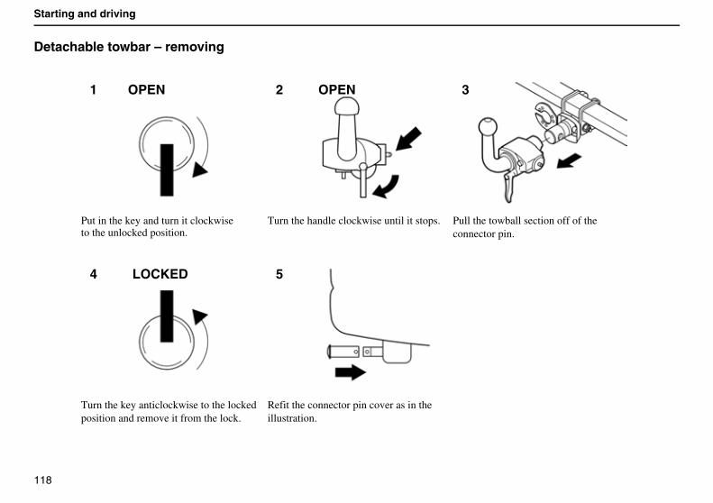
118
Starting and driving
Detachable towbar – removing�
Put in the key and turn it clockwiseto the unlocked position.
Turn the handle clockwise until it stops. Pull the towball section off of the connector pin.
Turn the key anticlockwise to the locked position and remove it from the lock.
Refit the connector pin cover as in the illustration.
OPEN1 OPEN2 3
4 LOCKED 5
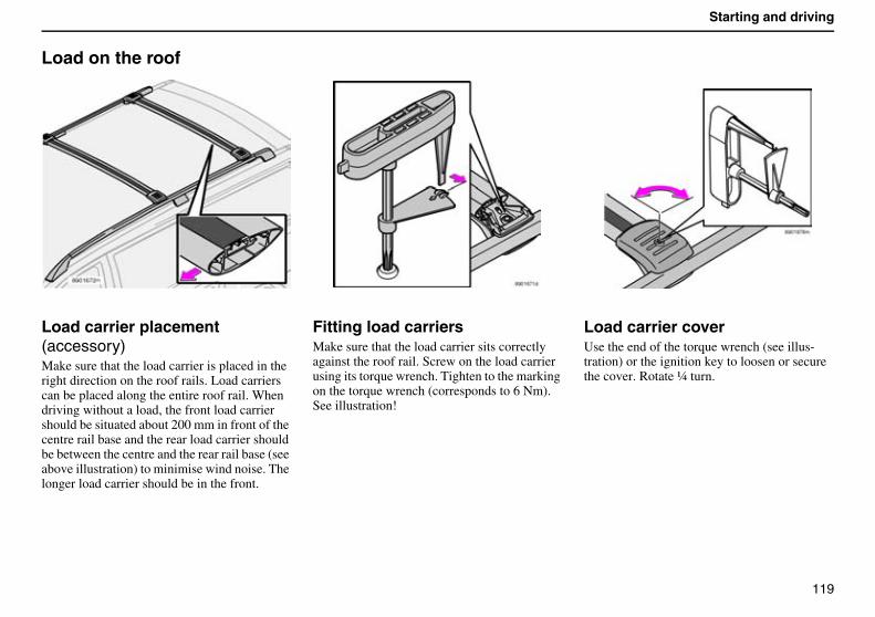
119
Starting and driving
Load on the roof
Load carrier placement (accessory)Make sure that the load carrier is placed in the right direction on the roof rails. Load carriers can be placed along the entire roof rail. When driving without a load, the front load carrier should be situated about 200 mm in front of the centre rail base and the rear load carrier should be between the centre and the rear rail base (see above illustration) to minimise wind noise. The longer load carrier should be in the front.
Fitting load carriersMake sure that the load carrier sits correctly against the roof rail. Screw on the load carrier using its torque wrench. Tighten to the marking on the torque wrench (corresponds to 6 Nm). See illustration!
Load carrier coverUse the end of the torque wrench (see illus-tration) or the ignition key to loosen or secure the cover. Rotate ¼ turn.
120
Starting and driving
Using load carriers• To avoid damaging your car and to
achieve the best level of safety when driving, we recommend that you only use load carriers that Volvo has specially designed for your car.
• Check periodically that the load carriers and load are properly secured. Lash the load securely with retaining straps!
• You can carry a maximum of 100 kg on the roof (including load carriers).
• Distribute the load evenly over the load carriers. Do not load lopsidedly! Place the heaviest items at the bottom.
• Remember that the car’s centre of gravity and driving characteristics change if you have a load on the roof.
• Keep in mind that the car’s wind resistance and fuel consumption increase in proportion to the size of the load.
• Drive gently! Avoid quick accelerations, heavy braking and taking curves hard.
121
Wheels and tyres
General 122
Tyre pressure 125
Changing wheels 126
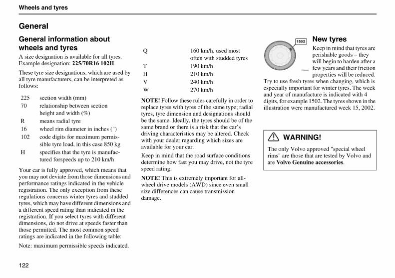
122
Wheels and tyres
General
General information about wheels and tyresA size designation is available for all tyres. Example designation: ))-1/5%(.�(5)D.
These tyre size designations, which are used by all tyre manufacturers, can be interpreted as follows:
Your car is fully approved, which means that you may not deviate from those dimensions and performance ratings indicated in the vehicle registration. The only exception from these regulations concerns winter tyres and studded tyres, which may have different dimensions and a different speed rating than indicated in the registration. If you select tyres with different dimensions, do not drive at speeds faster than those permitted. The most common speed ratings are indicated in the following table:
Note: maximum permissible speeds indicated.
������Follow these rules carefully in order to replace tyres with tyres of the same type; radial tyres, tyre dimension and designations should be the same. Ideally, the tyres should be of the same brand or there is a risk that the car’s driving characteristics may be altered. Check with your dealer regarding which sizes are available for your car.
Keep in mind that the road surface conditions determine how fast you may drive, not the tyre speed rating.
������This is extremely important for all-wheel drive models (AWD) since even small size differences can cause transmission damage.
New tyresKeep in mind that tyres are perishable goods – they will begin to harden after a few years and their friction properties will be reduced.
Try to use fresh tyres when changing, which is especially important for winter tyres. The week and year of manufacture is indicated with 4 digits, for example 1502. The tyres shown in the illustration were manufactured week 15, 2002.
225 section width (mm)70 relationship between section
height and width (%)R means radial tyre16 wheel rim diameter in inches (")102 code digits for maximum permis-
sible tyre load, in this case 850 kgH specifies that the tyre is manufac-
tured forspeeds up to 210 km/h
Q 160 km/h, used most often with studded tyres
T 190 km/hH 210 km/hV 240 km/hW 270 km/h
WARNING!
The only Volvo approved "special wheel rims" are those that are tested by Volvo and are :�����E������!! �� .
123
Wheels and tyres
Winter tyresVolvo recommends winter tyres of size 225/70 R16 for all XC90 cars except those seating seven and those with T6 engines. Size 235/65R17 is recommended for these instead.
Always use winter tyres on all four wheels!
������Consult your Volvo dealer for advice on which rim and tyre type you should use for your car.
Studded tyresStudded winter tyres should be carefully "broken in" over a distance of 500-1000 km so that the studs become properly positioned in the tyre. This will provide both the tyres and studs with a longer service life while contributing to a quieter ride.
Remember that regulations for use of studded tyres vary from country to country.
�����!���� Snow chains may only be used on the front wheels.
������Always use Volvo-approved snow chains only; other snow chains can damage your car.Never drive faster than 50 km/h with snow chains!Do not drive on bare roads unnecessarily as this causes heavy wear on both snow chains and tyres.
������Never use "quick links" because the space between the disc brakes and the wheels is too small.
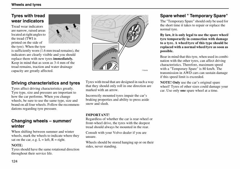
124
Wheels and tyres
Tyres with tread wear indicatorsTread wear indicators are narrow, raised areas located at right angles to the tread (TWI is printed on the side of the tyre). When the tyre is sufficiently worn (1.6 mm tread remains), the indicators are clearly visible and you should replace them with new tyres �''������$ Keep in mind that as soon as 3-4 mm of the tread remains, traction and water drainage capacity are greatly affected.
Driving characteristics and tyresTyres affect driving characteristics greatly. Tyre type, size and pressure are important to how the car performs. When you change wheels, be sure to use the same type, size and brand on all four wheels. Follow the recommen-dations regarding tyre pressure.
Changing wheels – summer/winterWhen shifting between summer and winter wheels, mark the wheels to indicate where they sat on the car, e.g. L = left, R = right.
�����Tyres should have the same rotational direction throughout their service life.
Tyres with tread that are designed in such a way that they should only roll in one direction are marked with an arrow.
Incorrectly mounted tyres impair the car’s braking properties and ability to press aside snow and slush.
�0��%������Regardless of whether the car is rear-wheel or front-wheel drive, the tyres with the deepest tread should always be mounted in the rear.
Consult with your Volvo dealer if you are unsure.
Wheels should be stored hanging up or on their sides, never standing.
Spare wheel " Temporary Spare" The "Temporary Spare" should only be used for the short time it takes to repair or replace the normal tyre.
8�����,����� ��������������� ���� ������1����'����������!���!������������'����������$������1���� ���� ����� �����������!�����������'������1���� � ����� ��� ���$
Bear in mind that this tyre, when used in combi-nation with the other tyres, can affect driving characteristics. Therefore, maximum speed with a "Temporary Spare" is 80 km/h. The transmission in AWD cars can sustain damage if this speed limit is exceeded.
�����������use the car’s original spare wheel! Tyres of other sizes could damage your car. Use only �� spare wheel at a time.
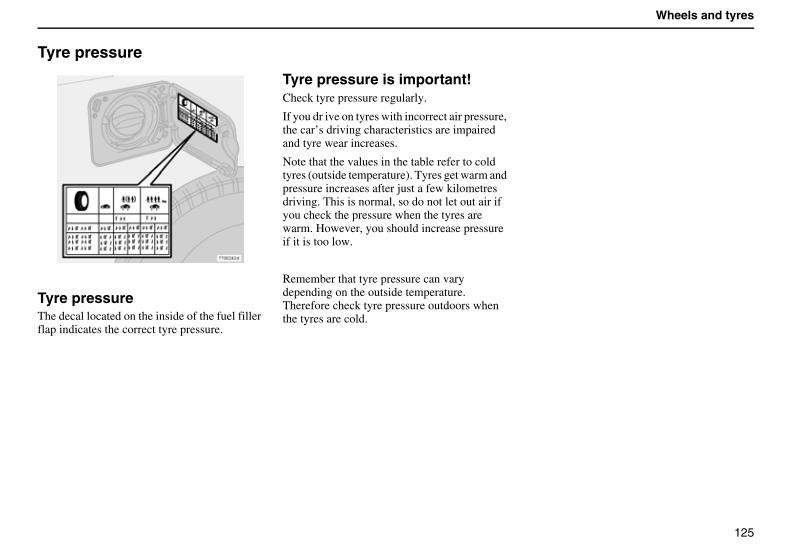
125
Wheels and tyres
Tyre pressure
Tyre pressureThe decal located on the inside of the fuel filler flap indicates the correct tyre pressure.
Tyre pressure is important!Check tyre pressure regularly.
If you dr ive on tyres with incorrect air pressure, the car’s driving characteristics are impaired and tyre wear increases.
Note that the values in the table refer to cold tyres (outside temperature). Tyres get warm and pressure increases after just a few kilometres driving. This is normal, so do not let out air if you check the pressure when the tyres are warm. However, you should increase pressure if it is too low.
Remember that tyre pressure can vary depending on the outside temperature. Therefore check tyre pressure outdoors when the tyres are cold.
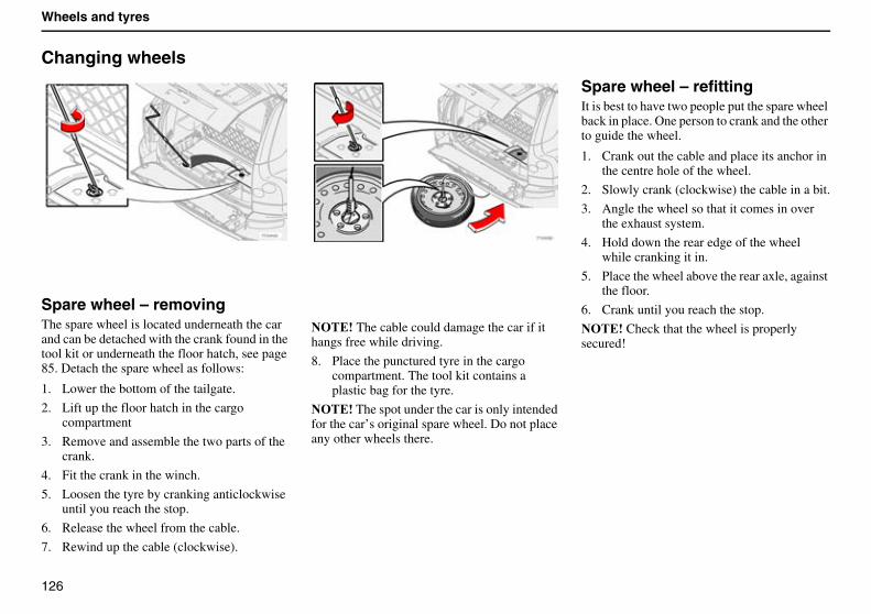
126
Wheels and tyres
Changing wheels
Spare wheel – removingThe spare wheel is located underneath the car and can be detached with the crank found in the tool kit or underneath the floor hatch, see page 85. Detach the spare wheel as follows:
1. Lower the bottom of the tailgate.
2. Lift up the floor hatch in the cargo compartment
3. Remove and assemble the two parts of the crank.
4. Fit the crank in the winch.
5. Loosen the tyre by cranking anticlockwise until you reach the stop.
6. Release the wheel from the cable.
7. Rewind up the cable (clockwise).
������The cable could damage the car if it hangs free while driving.
8. Place the punctured tyre in the cargo compartment. The tool kit contains a plastic bag for the tyre.
������The spot under the car is only intended for the car’s original spare wheel. Do not place any other wheels there.
Spare wheel – refittingIt is best to have two people put the spare wheel back in place. One person to crank and the other to guide the wheel.
1. Crank out the cable and place its anchor in the centre hole of the wheel.
2. Slowly crank (clockwise) the cable in a bit.
3. Angle the wheel so that it comes in over the exhaust system.
4. Hold down the rear edge of the wheel while cranking it in.
5. Place the wheel above the rear axle, against the floor.
6. Crank until you reach the stop.
������Check that the wheel is properly secured!
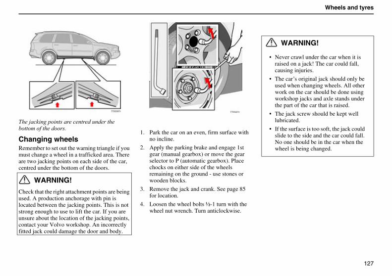
127
Wheels and tyres
$���>��� ����� ��������������'�������������!�������������
Changing wheelsRemember to set out the warning triangle if you must change a wheel in a trafficked area. There are two jacking points on each side of the car, centred under the bottom of the doors.
WARNING!
Check that the right attachment points are being used. A production anchorage with pin is located between the jacking points. This is not strong enough to use to lift the car. If you are unsure about the location of the jacking points, contact your Volvo workshop. An incorrectly fitted jack could damage the door and body.
1. Park the car on an even, firm surface with no incline.
2. Apply the parking brake and engage 1st gear (manual gearbox) or move the gear selector to P (automatic gearbox). Place chocks on either side of the wheels remaining on the ground - use stones or wooden blocks.
3. Remove the jack and crank. See page 85 for location.
4. Loosen the wheel bolts ½-1 turn with the wheel nut wrench. Turn anticlockwise.
WARNING!
• Never crawl under the car when it is raised on a jack! The car could fall, causing injuries.
• The car’s original jack should only be used when changing wheels. All other work on the car should be done using workshop jacks and axle stands under the part of the car that is raised.
• The jack screw should be kept well lubricated.
• If the surface is too soft, the jack could slide to the side and the car could fall. No one should be in the car when the wheel is being changed.
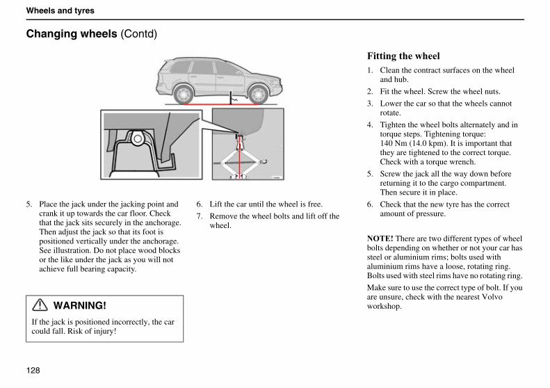
128
Wheels and tyres
Changing wheels (Contd)
5. Place the jack under the jacking point and crank it up towards the car floor. Check that the jack sits securely in the anchorage. Then adjust the jack so that its foot is positioned vertically under the anchorage. See illustration. Do not place wood blocks or the like under the jack as you will not achieve full bearing capacity.
6. Lift the car until the wheel is free.
7. Remove the wheel bolts and lift off the wheel.
7�������������1. Clean the contract surfaces on the wheel
and hub.
2. Fit the wheel. Screw the wheel nuts.
3. Lower the car so that the wheels cannot rotate.
4. Tighten the wheel bolts alternately and in torque steps. Tightening torque:140 Nm (14.0 kpm). It is important that they are tightened to the correct torque. Check with a torque wrench.
5. Screw the jack all the way down before returning it to the cargo compartment. Then secure it in place.
6. Check that the new tyre has the correct amount of pressure.
������There are two different types of wheel bolts depending on whether or not your car has steel or aluminium rims; bolts used with aluminium rims have a loose, rotating ring. Bolts used with steel rims have no rotating ring.
Make sure to use the correct type of bolt. If you are unsure, check with the nearest Volvo workshop. WARNING!
If the jack is positioned incorrectly, the car could fall. Risk of injury!
129
Car care
Cleaning 130
Repairing paintwork damage 132
Rustproofing 133
130
Car care
Cleaning
Wash the car often!Wash the car as soon as it becomes dirty, especially in the winter when road salt and moisture can lead to corrosion.
Wash the car as follows:
• Thoroughly rinse dirt off the underbody of the car.
• Rinse the entire car until the dirt has softened. When using high pressure washer: Make sure nozzle of the high pressure washer does not come closer than 30 cm from the bodywork. Do not spray the locks directly or the fuel filler flap at an angle from behind.
• Wash with a sponge using a lot of water with or without detergent.
• You can use lukewarm (maximum 35°C) but not hot water.
• If the dirt is ingrained, you can wash the car with cold degreasing agent, but then be sure that there is a drain separator where you are washing the car. When using cold degreasing agent, ensure that the car is not in direct sunlight or that the paint is warm from sunlight or a warm engine. Sunlight and heat can cause permanent damage. Consult your Volvo workshop.
• Dry the car with a clean, soft chamois.
• Clean the wiper blades with a lukewarm soap solution.
Suitable detergent
Car shampoo.
Bear in mind:
Always wash ����������� off the paintwork as soon as possible.
Bird droppings contain chemicals that affect and discolour paintwork quickly. The discolor-ation cannot be polished off.
Clean the electric contacts of the electric engine heater and trailer coupling (option).
Automatic car washAn automatic car wash is a simple and quick way of washing the car. Bear in mind, however, that an automatic car wash can never replace a proper handwashing – the brushes of a car wash cannot reach everywhere. During the first months of the car’s life we recommend that you handwash the car.
WARNING!
Do not wash the engine when it is warm. Risk of fire! Allow an authorised Volvo workshop to wash the engine.
WARNING!
� ���� ����������� �� �������# so that moisture and corrosion do not affect the brake lining and impair the brakes! Lightly depress the brake pedal now and then when driving long distances in rain or slush so that the brake lining warms and dries. You should also do this when you begin driving after damp or cold weather.
131
Car care
Cleaning the upholsteryTreating marks on fabric
A special cleaning agent available at your Volvo dealer is recommended when cleaning fabric upholstery. Other chemicals can impair the fire retardant qualities of the upholstery.
Treating marks on vinyl
��� scrape or rub a mark. �� use strong stain remover. Wash with a weak soap solution and lukewarm water.
Treating marks on leather
A special cleaning agent available at your Volvo dealer is recommended when cleaning leather upholstery.
Use the Volvo leather care kit once or twice a year to preserve suppleness and comfort.
�� use strong detergent, petrol, alcohol, white spirit, etc. as such strong substances can damage fabric, vinyl and leather upholstery.
Cleaning seat beltsUse water and synthetic detergent.
Polishing and waxingPolish and wax the car when you feel the paintwork is matte and when you wish to give the paintwork extra protection, such as before winter.
The car does not usually need polishing until after one year. It can be waxed earlier.
Wash and dry the car thoroughly before you begin polishing and/or waxing. Clean off asphalt and tar stains with white spirit. More stubborn marks can be removed with fine rubbing paste designed for paintwork. Polish first with a polish and then wax with liquid or solid wax. Carefully follow the instructions on the package. Many preparations contain both polish and wax.
Do not polish or wax surfaces warmer than 45°C.
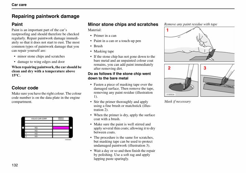
132
Car care
Repairing paintwork damage
PaintPaint is an important part of the car’s rustproofing and should therefore be checked regularly. Repair paintwork damage immedi-ately so that it does not start to rust. The most common types of paintwork damage that you can repair yourself are:
• minor stone chips and scratches
• damage to wing edges and door
3�����������������#,����!�� ��������!�������������������'����������(-F"$
Colour codeMake sure you have the right colour. The colour code number is on the data plate in the engine compartment.
Minor stone chips and scratchesMaterial:
• Primer in a can
• Paint in a can or a touch-up pen
• Brush
• Masking tape
• If the stone chip has not gone down to the bare metal and an unpainted colour coat remains, you can add paint immediately after removing dirt.
Do as follows if the stone chip went down to the bare metal
• Fasten a piece of masking tape over the damaged surface. Then remove the tape, removing any paint residue (illustration 1).
• Stir the primer thoroughly and apply using a fine brush or matchstick (illus-tration 2).
• When the primer is dry, apply the surface coat with a brush.
• Make sure the paint is well stirred and apply several thin coats; allowing it to dry between coats.
• The procedure is the same for scratches, but masking tape can be used to protect undamaged paintwork (illustration 3).
• Wait a day or so and then finish the repair by polishing. Use a soft rag and apply lapping paste sparingly.
��!������ ��� ����� �'��� �������
����� ���������
1
2 3
133
Car care
Rustproofing
Rustproofing – check and repairYour car received a thorough and complete rustproofing at the factory. Parts of the body are made of galvanised sheet metal. The underbody is protected by a wear-resistant anti-corrosion compound. Members, cavities and enclosed sections are sprayed with a thin, penetrating rust inhibitor.
The car’s rustproofing is maintained by doing the following:
• Keep the car clean! Hose down the underbody. When high pressure washing, hold the nozzle at least 30 cm from painted surfaces!
• Regularly check and touch-up the rustproofing treatment as necessary.
The car’s rustproofing does not normally require treatment for approximately 8 years. After that time, it should be treated at three year intervals. If your car requires treatment, consult your Volvo workshop.
RepairIf you want to repair the rustproofing yourself, make sure the area is clean and dry. Hose down, wash and dry the car thoroughly. Use a rustproofing agent in a spray can or one that is intended for brush application.
There are two different types of rustproofing agents:
a) thin (colourless), for visible areas
b) thick, for areas prone to wear on the underbody
Possible repair areas with these agents:
• Visible welds and sheet metal joints; thin fluid
• Underbody; thick fluid
• Door hinges; thin fluid
• Bonnet hinges and catch; thin fluid
Once you have finished treatment, excess rustproofing can be wiped off with a rag dipped in a recommended cleaning agent. Parts of the engine and suspension strut mountings in the engine compartment are treated at the factory with a wax-based, colourless rustproofing. This withstands normal detergents without dissolving and losing its rustproofing ability.
If you wash the engine using aromatic solvents, such as turpentine or white spirit (especially those that do not contain emulsifiers), the protective wax should be renewed after washing. Your Volvo dealer handles such waxes.

134
Car care
135
Maintenance and service
Volvo service 136
Maintenance 137
Bonnet and engine compartment 138
Diesel 139
Oils and fluids 140
Wiper blades 144
Battery 145
Bulbs 147
Replacing bulbs 148
Fuses 155
136
Maintenance and service
Volvo service
Volvo service programmeBefore the car left the factory, it was thoroughly test driven. It was checked again in accordance with Volvo Car Corporation regulations before it was handed over to you.
To keep your Volvo as safe and reliable as possible, follow the Volvo service programme specified in the Service and Warranty Manual. We advise that you always let an authorised Volvo workshop perform service and mainte-nance work. Your Volvo workshop has the personnel, special tools and service literature that guarantee the highest quality of service. Your Volvo workshop always uses Volvo Genuine parts. The Volvo service programme is developed for normal driving conditions.
IMPORTANT�
For the Volvo warranty to apply, check and follow the instructions in the Service and Warranty Manuals.
Adverse driving conditionsChange engine oil and replace air and oil filters more often than recommended in the Service and Warranty manual when driving in adverse conditions.
Adverse driving conditions include:
• Prolonged driving in dusty/sandy condi-tions
• Prolonged driving with caravan and/or trailer
• Prolonged driving in mountainous areas
• Prolonged driving at high speeds
• Prolonged idling and/ordriving at low speeds
• Driving in low temperatures– below 0°C – along shorter distances; less than 10 km.
Environmental careThere are many examples of environmental care within the Volvo field of activity. We use a chlorine-free refrigerant in our climate control systems that is harmless to the ozone layer and contributes very little to the greenhouse effect. Asbestos-free brakes, engines with catalytic converters and biogas operation are other examples of what Volvo Car Corporation is doing for the environment.
Our specific services are also of importance to the environment, such as using Volvo Genuine parts, maintaining ignition and fuel systems, and other measures that directly reduce exhaust emission. We would also like to point out the care taken by our Volvo workshops in regards to handling environmentally dangerous substances.
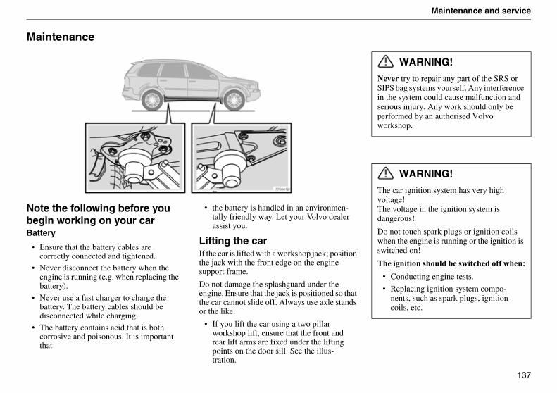
137
Maintenance and service
Maintenance
Note the following before you begin working on your carBattery
• Ensure that the battery cables are correctly connected and tightened.
• Never disconnect the battery when the engine is running (e.g. when replacing the battery).
• Never use a fast charger to charge the battery. The battery cables should be disconnected while charging.
• The battery contains acid that is both corrosive and poisonous. It is important that
• the battery is handled in an environmen-tally friendly way. Let your Volvo dealer assist you.
Lifting the carIf the car is lifted with a workshop jack; position the jack with the front edge on the engine support frame.
Do not damage the splashguard under the engine. Ensure that the jack is positioned so that the car cannot slide off. Always use axle stands or the like.
• If you lift the car using a two pillar workshop lift, ensure that the front and rear lift arms are fixed under the lifting points on the door sill. See the illus-tration.
WARNING!
�� try to repair any part of the SRS or SIPS bag systems yourself. Any interference in the system could cause malfunction and serious injury. Any work should only be performed by an authorised Volvo workshop.
WARNING!
The car ignition system has very high voltage!The voltage in the ignition system is dangerous!
Do not touch spark plugs or ignition coils when the engine is running or the ignition is switched on!
������������ �������� ���!���� �����
• Conducting engine tests.
• Replacing ignition system compo-nents, such as spark plugs, ignition coils, etc.
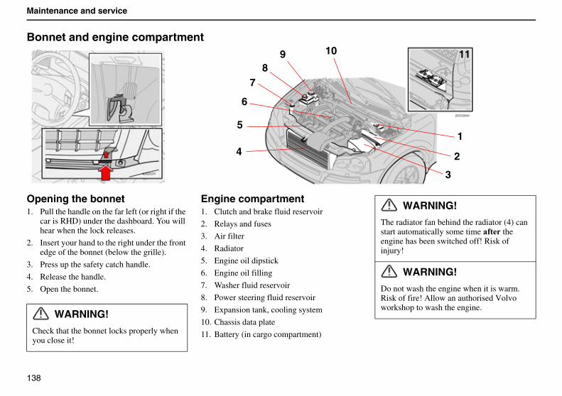
138
Maintenance and service
Bonnet and engine compartment
Opening the bonnet1. Pull the handle on the far left (or right if the
car is RHD) under the dashboard. You will hear when the lock releases.
2. Insert your hand to the right under the front edge of the bonnet (below the grille).
3. Press up the safety catch handle.
4. Release the handle.
5. Open the bonnet.
Engine compartment1. Clutch and brake fluid reservoir
2. Relays and fuses
3. Air filter
4. Radiator
5. Engine oil dipstick
6. Engine oil filling
7. Washer fluid reservoir
8. Power steering fluid reservoir
9. Expansion tank, cooling system
10. Chassis data plate
11. Battery (in cargo compartment)
5
6
1
2
3
4
78
9 10 11
WARNING!
Check that the bonnet locks properly when you close it!
WARNING!
The radiator fan behind the radiator (4) can start automatically some time � � the engine has been switched off! Risk of injury!
WARNING!
Do not wash the engine when it is warm. Risk of fire! Allow an authorised Volvo workshop to wash the engine.
139
Maintenance and service
Diesel
Fuel systemDiesel engines are sensitive to contaminants. Only use diesel from a well-know oil company. Never fill up with diesel if the quality is dubious. Special diesel for winter use is available from the large oil companies. This fuel is less viscous at low temperatures and reduces the risk of wax building up in the fuel system.
The risk of condensation building up in the tank is reduced if the tank is kept well filled. When refuelling, check that the area around the fuel filler pipe is clean.
Avoid spilling onto the paintwork. Wash off any spills with detergent and water.
Empty tankNo special procedures are required if the tank runs dry. The fuel system is bled automatically.
RME (Rape Methyl Ester)• Diesel may be mixed with max. 5%
RME.
������A risk for engine damage occurs if the RME concentration is greater than 5%.
Draining condensation from the fuel filterThe fuel filter removes condensation, which could otherwise affect engine function, from the fuel. The fuel filter should be drained as specified in the Service and Warranty Book, and when you suspect that the car has been filled with contaminated fuel.
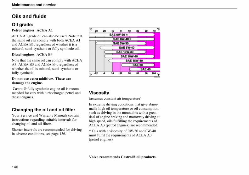
140
Maintenance and service
Oils and fluids
Oil grade:��������� ���"����(
ACEA A3 grade oil can also be used. Note that the same oil can comply with both ACEA A1 and ACEA B1, regardless of whether it is a mineral, semi-synthetic or fully synthetic oil.
�� ������ ���"���8+
Note that the same oil can comply with ACEA A3, ACEA B3 and ACEA B4, regardless of whether the oil is mineral, semi-synthetic or fully synthetic.
�������� �6���������� $��� �!�����'����������$
Castrol® fully synthetic engine oil is recom-mended for cars with turbocharged petrol and diesel engines.
Changing the oil and oil filterYour Service and Warranty Manuals contain instructions regarding suitable intervals for changing oil and oil filters.
Shorter intervals are recommended for driving in adverse conditions, see page 136.
Viscosity(assumes constant air temperature)
In extreme driving conditions that give abnor-mally high oil temperature or oil consumption, such as driving in the mountains with a great deal of engine braking and motorway driving at high speed, oils fulfilling the requirements of ACEA A3 (petrol engines) are recommended.
* Oils with a viscosity of 0W-30 and 0W-40 must fulfil the requirements of ACEA A3 (petrol engines).
:�����!�''�� �"� ���G���������!� $
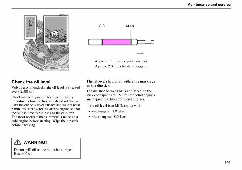
141
Maintenance and service
Check the oil levelVolvo recommends that the oil level is checked every 2500 km.
Checking the engine oil level is especially important before the first scheduled oil change. Park the car on a level surface and wait at least 5 minutes after switching off the engine so that the oil has time to run back to the oil sump.The most accurate measurement is made on a cold engine before starting. Wipe the dipstick before checking.
����������� ������ ��������������'�#��� ���������� ��!#$
The distance between MIN and MAX on the stick corresponds to 1.5 litres for petrol engines and approx. 2.0 litres for diesel engines.
If the oil level is at MIN, top up with:
• cold engine - 1.0 litre
• warm engine - 0.5 litres
WARNING!
Do not spill oil on the hot exhaust pipes. Rise of fire!
MIN MAX
Approx. 1.5 litres for petrol enginesApprox. 2.0 litres for diesel engines
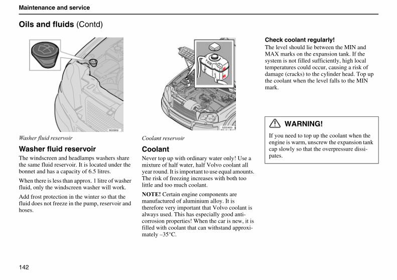
142
Maintenance and service
Oils and fluids (Contd)
5������' �������
Washer fluid reservoirThe windscreen and headlamps washers share the same fluid reservoir. It is located under the bonnet and has a capacity of 6.5 litres.
When there is less than approx. 1 litre of washer fluid, only the windscreen washer will work.
Add frost protection in the winter so that the fluid does not freeze in the pump, reservoir and hoses.
������������
CoolantNever top up with ordinary water only! Use a mixture of half water, half Volvo coolant all year round. It is important to use equal amounts. The risk of freezing increases with both too little and too much coolant.
������Certain engine components are manufactured of aluminium alloy. It is therefore very important that Volvo coolant is always used. This has especially good anti-corrosion properties! When the car is new, it is filled with coolant that can withstand approxi-mately –35°C.
Check coolant regularly!The level should lie between the MIN and MAX marks on the expansion tank. If the system is not filled sufficiently, high local temperatures could occur, causing a risk of damage (cracks) to the cylinder head. Top up the coolant when the level falls to the MIN mark.
WARNING!
If you need to top up the coolant when the engine is warm, unscrew the expansion tank cap slowly so that the overpressure dissi-pates.
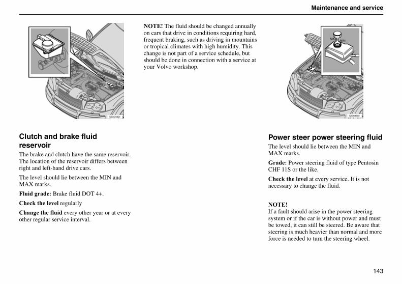
143
Maintenance and service
Clutch and brake fluidreservoirThe brake and clutch have the same reservoir. The location of the reservoir differs between right and left-hand drive cars.
The level should lie between the MIN and MAX marks.
7����������Brake fluid DOT 4+.
"�!#������� regularly
"�������� ���� every other year or at every other regular service interval.
������The fluid should be changed annually on cars that drive in conditions requiring hard, frequent braking, such as driving in mountains or tropical climates with high humidity. This change is not part of a service schedule, but should be done in connection with a service at your Volvo workshop.
Power steer power steering fluidThe level should lie between the MIN and MAX marks.
E����Power steering fluid of type Pentosin CHF 11S or the like.
"�!#��������at every service. It is not necessary to change the fluid.
������If a fault should arise in the power steering system or if the car is without power and must be towed, it can still be steered. Be aware that steering is much heavier than normal and more force is needed to turn the steering wheel.
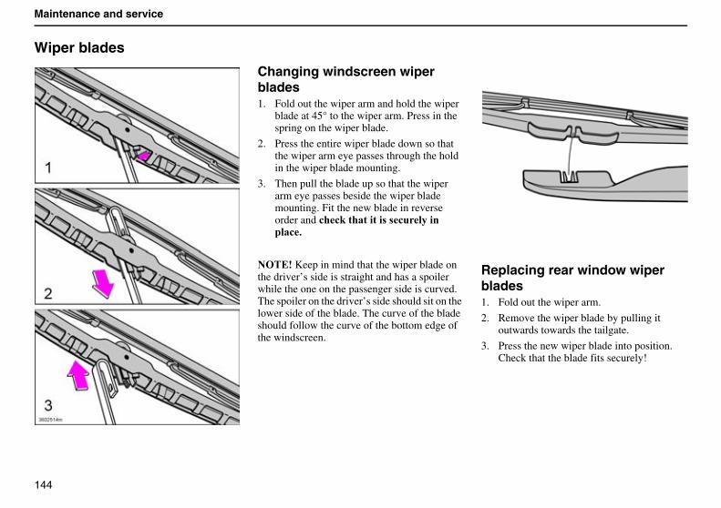
144
Maintenance and service
Wiper blades
Changing windscreen wiper blades1. Fold out the wiper arm and hold the wiper
blade at 45° to the wiper arm. Press in the spring on the wiper blade.
2. Press the entire wiper blade down so that the wiper arm eye passes through the hold in the wiper blade mounting.
3. Then pull the blade up so that the wiper arm eye passes beside the wiper blade mounting. Fit the new blade in reverse order and !�!#���������� � !����������!$
������Keep in mind that the wiper blade on the driver’s side is straight and has a spoiler while the one on the passenger side is curved. The spoiler on the driver’s side should sit on the lower side of the blade. The curve of the blade should follow the curve of the bottom edge of the windscreen.
Replacing rear window wiper blades1. Fold out the wiper arm.
2. Remove the wiper blade by pulling it outwards towards the tailgate.
3. Press the new wiper blade into position.Check that the blade fits securely!
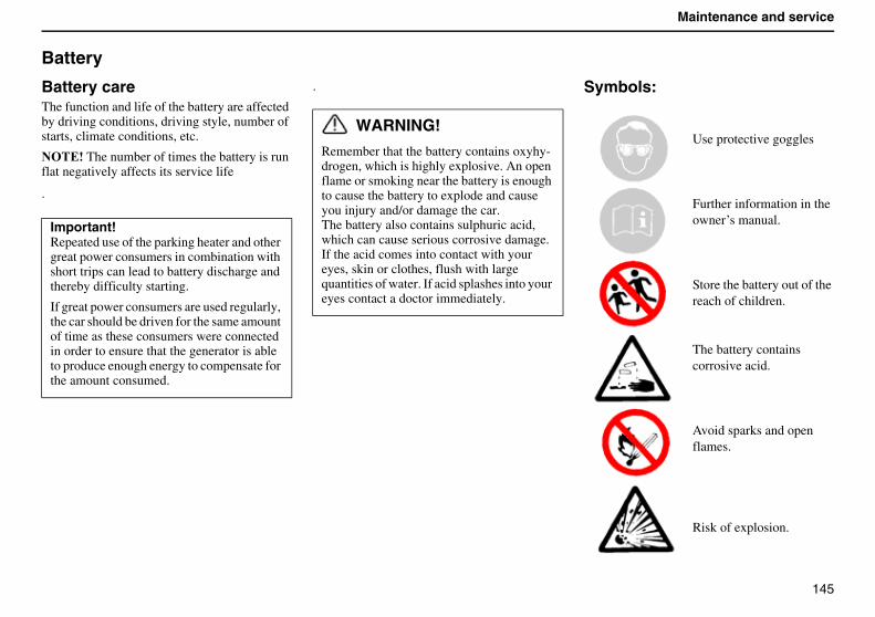
145
Maintenance and service
Battery
Battery careThe function and life of the battery are affected by driving conditions, driving style, number of starts, climate conditions, etc.
������The number of times the battery is run flat negatively affects its service life
.
. Symbols:
Use protective goggles
Further information in the owner’s manual.
Store the battery out of the reach of children.
The battery contains corrosive acid.
Avoid sparks and open flames.
Risk of explosion.
Important!Repeated use of the parking heater and other great power consumers in combination with short trips can lead to battery discharge and thereby difficulty starting.
If great power consumers are used regularly, the car should be driven for the same amount of time as these consumers were connected in order to ensure that the generator is able to produce enough energy to compensate for the amount consumed.
WARNING!
Remember that the battery contains oxyhy-drogen, which is highly explosive. An open flame or smoking near the battery is enough to cause the battery to explode and cause you injury and/or damage the car.The battery also contains sulphuric acid, which can cause serious corrosive damage. If the acid comes into contact with your eyes, skin or clothes, flush with large quantities of water. If acid splashes into your eyes contact a doctor immediately.
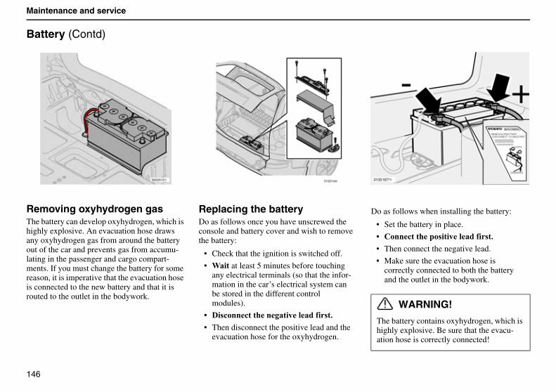
146
Maintenance and service
Battery (Contd)
Removing oxyhydrogen gasThe battery can develop oxyhydrogen, which is highly explosive. An evacuation hose draws any oxyhydrogen gas from around the battery out of the car and prevents gas from accumu-lating in the passenger and cargo compart-ments. If you must change the battery for some reason, it is imperative that the evacuation hose is connected to the new battery and that it is routed to the outlet in the bodywork.
Replacing the battery Do as follows once you have unscrewed the console and battery cover and wish to remove the battery:
• Check that the ignition is switched off.
• 3��� at least 5 minutes before touching any electrical terminals (so that the infor-mation in the car’s electrical system can be stored in the different control modules).
B �� !���!���������������� � �$
• Then disconnect the positive lead and the evacuation hose for the oxyhydrogen.
Do as follows when installing the battery:
• Set the battery in place.
B "���!������� ��������� � �$
• Then connect the negative lead.
• Make sure the evacuation hose is correctly connected to both the battery and the outlet in the bodywork.
WARNING!
The battery contains oxyhydrogen, which is highly explosive. Be sure that the evacu-ation hose is correctly connected!
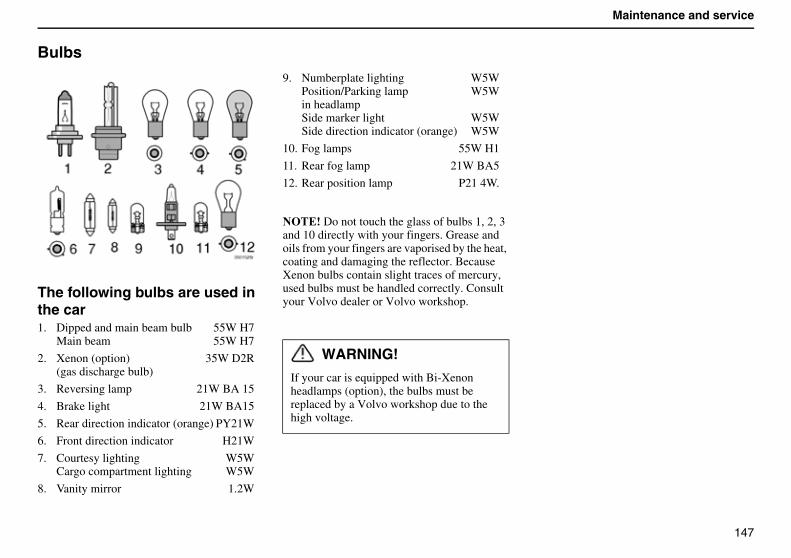
147
Maintenance and service
Bulbs
The following bulbs are used in the car1. Dipped and main beam bulb 55W H7
Main beam 55W H7
2. Xenon (option) 35W D2R(gas discharge bulb)
3. Reversing lamp 21W BA 15
4. Brake light 21W BA15
5. Rear direction indicator (orange) PY21W
6. Front direction indicator H21W
7. Courtesy lighting W5WCargo compartment lighting W5W
8. Vanity mirror 1.2W
9. Numberplate lighting W5WPosition/Parking lamp W5Win headlampSide marker light W5WSide direction indicator (orange) W5W
10. Fog lamps 55W H1
11. Rear fog lamp 21W BA5
12. Rear position lamp P21 4W.
������Do not touch the glass of bulbs 1, 2, 3 and 10 directly with your fingers. Grease and oils from your fingers are vaporised by the heat, coating and damaging the reflector. Because Xenon bulbs contain slight traces of mercury, used bulbs must be handled correctly. Consult your Volvo dealer or Volvo workshop.
WARNING!
If your car is equipped with Bi-Xenonheadlamps (option), the bulbs must be replaced by a Volvo workshop due to the high voltage.
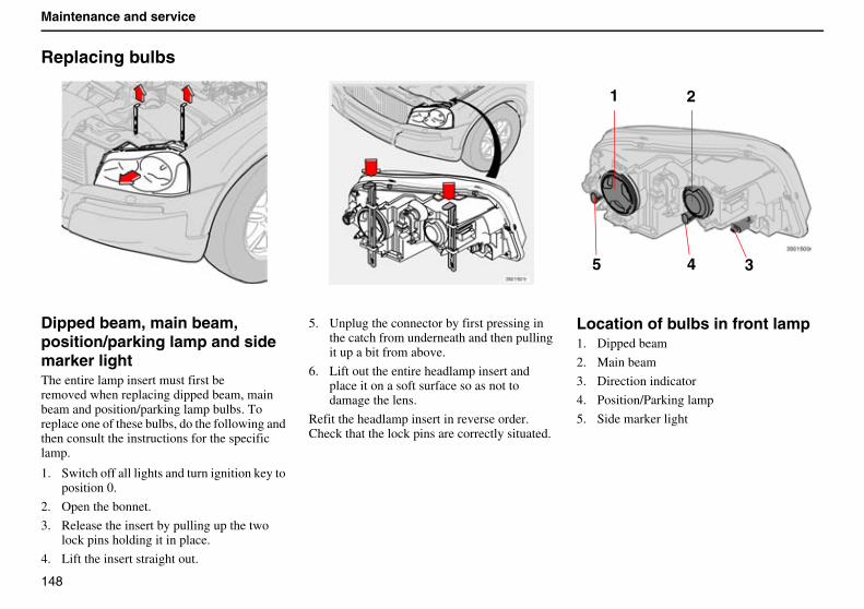
148
Maintenance and service
Replacing bulbs
Dipped beam, main beam, position/parking lamp and side marker lightThe entire lamp insert must first beremoved when replacing dipped beam, main beam and position/parking lamp bulbs. To replace one of these bulbs, do the following and then consult the instructions for the specific lamp.
1. Switch off all lights and turn ignition key to position 0.
2. Open the bonnet.
3. Release the insert by pulling up the two lock pins holding it in place.
4. Lift the insert straight out.
5. Unplug the connector by first pressing in the catch from underneath and then pulling it up a bit from above.
6. Lift out the entire headlamp insert and place it on a soft surface so as not to damage the lens.
Refit the headlamp insert in reverse order. Check that the lock pins are correctly situated.
Location of bulbs in front lamp1. Dipped beam
2. Main beam
3. Direction indicator
4. Position/Parking lamp
5. Side marker light
1 2
35 4
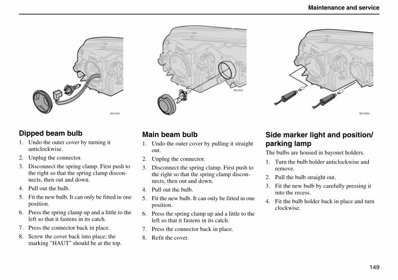
149
Maintenance and service
Dipped beam bulb1. Undo the outer cover by turning it
anticlockwise.
2. Unplug the connector.
3. Disconnect the spring clamp. First push to the right so that the spring clamp discon-nects, then out and down.
4. Pull out the bulb.
5. Fit the new bulb. It can only be fitted in one position.
6. Press the spring clamp up and a little to the left so that it fastens in its catch.
7. Press the connector back in place.
8. Screw the cover back into place; the marking "HAUT" should be at the top.
Main beam bulb�1. Undo the outer cover by pulling it straight
out.
2. Unplug the connector.
3. Disconnect the spring clamp. First push to the right so that the spring clamp discon-nects, then out and down.
4. Pull out the bulb.
5. Fit the new bulb. It can only be fitted in one position.
6. Press the spring clamp up and a little to the left so that it fastens in its catch.
7. Press the connector back in place.
8. Refit the cover.
Side marker light and position/ parking lampThe bulbs are housed in bayonet holders.
1. Turn the bulb holder anticlockwise and remove.
2. Pull the bulb straight out.
3. Fit the new bulb by carefully pressing it into the recess.
4. Fit the bulb holder back in place and turn clockwise.
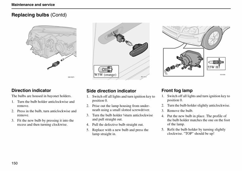
150
Maintenance and service
Replacing bulbs (Contd)
Direction indicatorThe bulbs are housed in bayonet holders.
1. Turn the bulb holder anticlockwise and remove.
2. Press in the bulb, turn anticlockwise and remove.
3. Fit the new bulb by pressing it into the recess and then turning clockwise.
Side direction indicator1. Switch off all lights and turn ignition key to
position 0.
2. Prise out the lamp housing from under-neath using a small slotted screwdriver.
3. Turn the bulb holder ¼turn anticlockwise and pull straight out.
4. Pull the defective bulb straight out.
5. Replace with a new bulb and press the lamp straight in.
Front fog lamp1. Switch off all lights and turn ignition key to
position 0.
2. Turn the bulb holder slightly anticlockwise.
3. Remove the bulb.
4. Put the new bulb in place. The profile of the bulb holder matches the one on the foot of the lamp.
5. Refit the bulb holder by turning slightly clockwise. "TOP" should be up!
W5W (orange)
55W H1
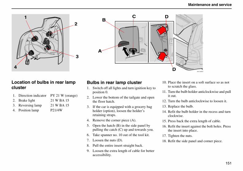
151
Maintenance and service
Location of bulbs in rear lamp cluster
Bulbs in rear lamp cluster1. Switch off all lights and turn ignition key to
position 0.
2. Lower the bottom of the tailgate and open the floor hatch.
3. If the car is equipped with a grocery bag holder (option), loosen the holder’s retaining straps.
4. Remove the corner piece (A).
5. Open the hatch (B) in the side panel by pulling the catch (C) up and towards you.
6. Take spanner no. 10 out of the tool kit.
7. Loosen the nuts (D).
8. Pull the entire insert straight back.
9. Loosen the extra length of cable for better accessibility.
10. Place the insert on a soft surface so as not to scratch the glass.
11. Turn the bulb holder anticlockwise and pull it out.
12. Turn the bulb anticlockwise to loosen it.
13. Replace the bulb.
14. Refit the bulb holder in the recess and turn clockwise.
15. Press back the extra length of cable.
16. Refit the insert against the bolt holes. Press the insert into place.
17. Tighten the nuts.
18. Refit the side panel and corner piece.
1. Direction indicator PY 21 W (orange)2. Brake light 21 W BA 153. Reversing lamp 21 W BA 154. Position lamp P21/4W
3
12
4
A
BC
D
D
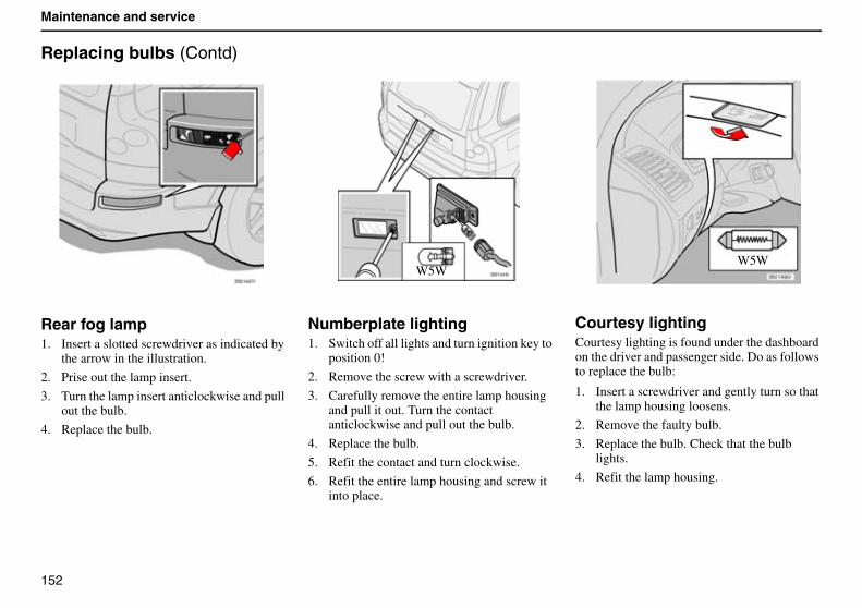
152
Maintenance and service
Replacing bulbs (Contd)
Rear fog lamp1. Insert a slotted screwdriver as indicated by
the arrow in the illustration.
2. Prise out the lamp insert.
3. Turn the lamp insert anticlockwise and pull out the bulb.
4. Replace the bulb.
Numberplate lighting1. Switch off all lights and turn ignition key to
position 0!
2. Remove the screw with a screwdriver.
3. Carefully remove the entire lamp housing and pull it out. Turn the contact anticlockwise and pull out the bulb.
4. Replace the bulb.
5. Refit the contact and turn clockwise.
6. Refit the entire lamp housing and screw it into place.
Courtesy lightingCourtesy lighting is found under the dashboard on the driver and passenger side. Do as follows to replace the bulb:
1. Insert a screwdriver and gently turn so that the lamp housing loosens.
2. Remove the faulty bulb.
3. Replace the bulb. Check that the bulb lights.
4. Refit the lamp housing.
W5WW5W
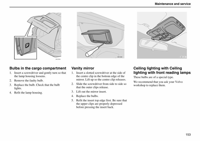
153
Maintenance and service
Bulbs in the cargo compartment1. Insert a screwdriver and gently turn so that
the lamp housing loosens.
2. Remove the faulty bulb.
3. Replace the bulb. Check that the bulb lights.
4. Refit the lamp housing.
Vanity mirror1. Insert a slotted screwdriver at the side of
the centre clip in the bottom edge of the mirror. Lift up so the centre clip releases.
2. Slide the screwdriver from side to side so that the outer clips release.
3. Lift out the mirror insert.
4. Replace the bulbs.
5. Refit the insert top edge first. Be sure that the upper clips are properly depressed before pressing the insert back.
Ceiling lighting with Ceiling lighting with front reading lampsThese bulbs are of a special type.
We recommend that you ask your Volvo workshop to replace them.
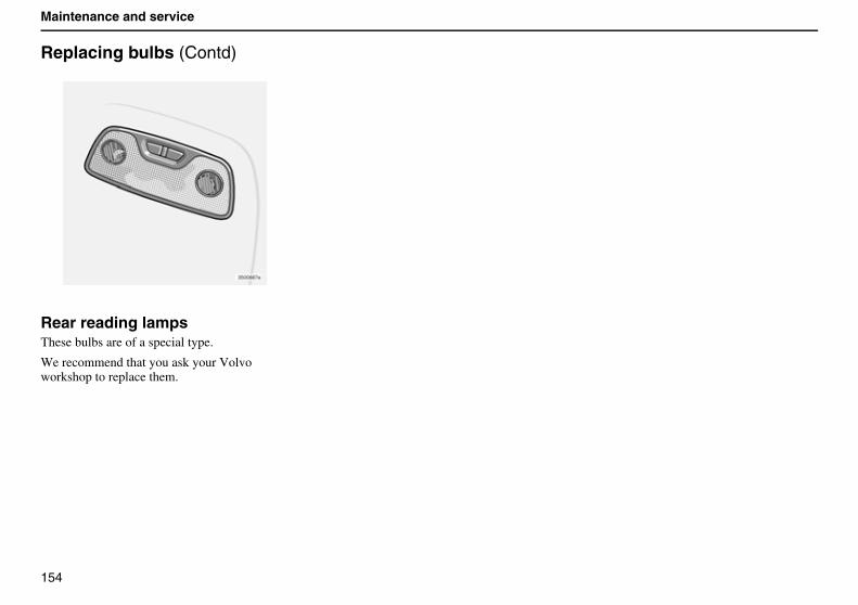
154
Maintenance and service
Replacing bulbs (Contd)
Rear reading lampsThese bulbs are of a special type.
We recommend that you ask your Volvo workshop to replace them.
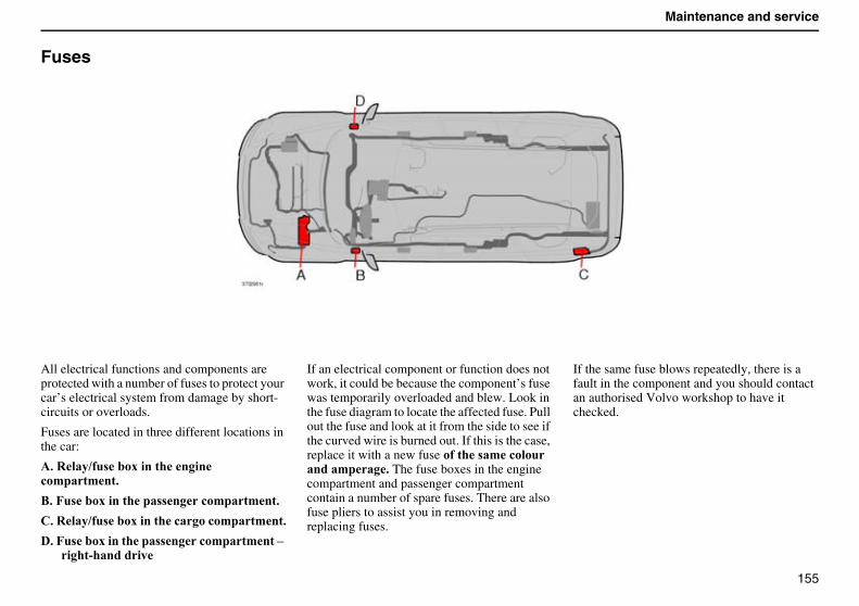
155
Maintenance and service
Fuses
All electrical functions and components are protected with a number of fuses to protect your car’s electrical system from damage by short-circuits or overloads.
Fuses are located in three different locations in the car:
������������ �����������������������������
�������� ��������������������������������
������������ ����������������������������
�������� ������������������������������������������������ �
If an electrical component or function does not work, it could be because the component’s fuse was temporarily overloaded and blew. Look in the fuse diagram to locate the affected fuse. Pull out the fuse and look at it from the side to see if the curved wire is burned out. If this is the case, replace it with a new fuse ������������������������������� The fuse boxes in the engine compartment and passenger compartment contain a number of spare fuses. There are also fuse pliers to assist you in removing and replacing fuses.
If the same fuse blows repeatedly, there is a fault in the component and you should contact an authorised Volvo workshop to have it checked.
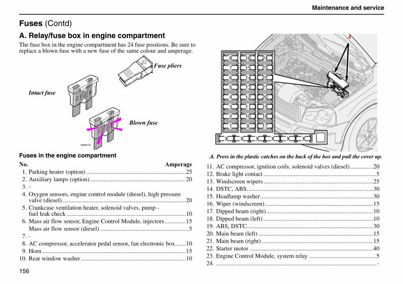
156
Maintenance and service
Fuses (Contd)
A. Relay/fuse box in engine compartmentThe fuse box in the engine compartment has 24 fuse positions. Be sure to replace a blown fuse with a new fuse of the same colour and amperage.
Fuses in the engine compartment��$ �'���1. Parking heater (option) .................................................................252. Auxiliary lamps (option)...............................................................203. -4. Oxygen sensors, engine control module (diesel), high pressure
valve (diesel) .................................................................................205. Crankcase ventilation heater, solenoid valves, pump -
fuel leak check ..............................................................................106. Mass air flow sensor, Engine Control Module, injectors..............15
Mass air flow sensor (diesel) ..........................................................57. -8. AC compressor, accelerator pedal sensor, fan electronic box.......109. Horn ..............................................................................................15
10. Rear window washer.....................................................................10
11. AC compressor, ignition coils, solenoid valves (diesel) ...............2012. Brake light contact ..........................................................................513. Windscreen wipers ........................................................................2514. DSTC, ABS...................................................................................3015. Headlamp washer..........................................................................3016. Wiper (windscreen).......................................................................1517. Dipped beam (right) ......................................................................1018. Dipped beam (left) ........................................................................1019. ABS, DSTC...................................................................................3020. Main beam (left) ...........................................................................1521. Main beam (right) .........................................................................1522. Starter motor .................................................................................4023. Engine Control Module, system relay ............................................524. ......................................................................................................... -
� �������
������ �
������� �
������ ����������� ���������� ������������������������� �����������������
�
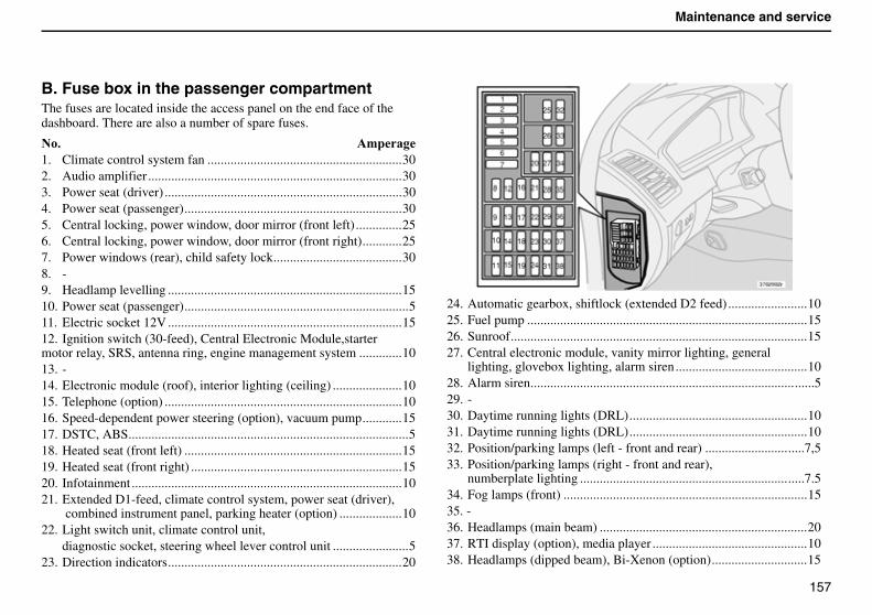
157
Maintenance and service
B. Fuse box in the passenger compartmentThe fuses are located inside the access panel on the end face of the dashboard. There are also a number of spare fuses.
��$ �'���1. Climate control system fan ...........................................................302. Audio amplifier .............................................................................303. Power seat (driver) ........................................................................304. Power seat (passenger)..................................................................305. Central locking, power window, door mirror (front left) ..............256. Central locking, power window, door mirror (front right)............257. Power windows (rear), child safety lock.......................................308. -9. Headlamp levelling .......................................................................1510. Power seat (passenger)....................................................................5 11. Electric socket 12V .......................................................................1512. Ignition switch (30-feed), Central Electronic Module,starter motor relay, SRS, antenna ring, engine management system .............1013. -14. Electronic module (roof), interior lighting (ceiling) .....................1015. Telephone (option) ........................................................................1016. Speed-dependent power steering (option), vacuum pump............1517. DSTC, ABS.....................................................................................518. Heated seat (front left) ..................................................................1519. Heated seat (front right) ................................................................1520. Infotainment ..................................................................................1021. Extended D1-feed, climate control system, power seat (driver),
combined instrument panel, parking heater (option) ...................1022. Light switch unit, climate control unit,
diagnostic socket, steering wheel lever control unit .......................523. Direction indicators.......................................................................20
24. Automatic gearbox, shiftlock (extended D2 feed) ........................1025. Fuel pump .....................................................................................1526. Sunroof..........................................................................................1527. Central electronic module, vanity mirror lighting, general
lighting, glovebox lighting, alarm siren........................................1028. Alarm siren......................................................................................529. -30. Daytime running lights (DRL)......................................................1031. Daytime running lights (DRL)......................................................1032. Position/parking lamps (left - front and rear) ..............................7,533. Position/parking lamps (right - front and rear),
numberplate lighting ....................................................................7.534. Fog lamps (front) ..........................................................................1535. -36. Headlamps (main beam) ...............................................................2037. RTI display (option), media player ...............................................1038. Headlamps (dipped beam), Bi-Xenon (option).............................15
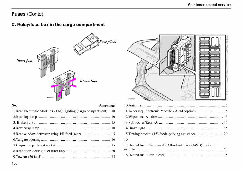
158
Maintenance and service
Fuses (Contd)
C. Relay/fuse box in the cargo compartment
��$ �'���
1.Rear Electronic Module (REM), lighting (cargo compartment) ... 10
2.Rear fog lamp ................................................................................ 10
3. Brake light .................................................................................... 15
4.Reversing lamp.............................................................................. 10
5.Rear window defroster, relay 15I-feed (rear) .................................. 5
6.Tailgate opening ............................................................................ 10
7.Cargo compartment socket............................................................ 15
8.Rear door locking, fuel filler flap.................................................. 20
9.Towbar (30 feed) ........................................................................... 15
10.Antenna ........................................................................................... 5
11.Accessory Electronic Module - AEM (option) ............................. 15
12.Wiper, rear window ....................................................................... 15
13.Subwoofer/Rear AC ...................................................................... 15
14.Brake light .................................................................................... 7.5
15.Towing bracket (15I-feed), parking assistance.............................. 20
16.-
17.Heated fuel filter (diesel), All-wheel drive (AWD) control module............................................................................................... 7.5
18.Heated fuel filter (diesel)............................................................... 15
� �������
������� �
������ �
159
Infotainment
Infotainment 160
Control panels 161
Audio functions 165
Radio functions 170
CD/MD (option) 182
CD changer (option) 184
Menu settings and selections – Audio 187
Telephone system 189
Telephone functions (option) 191
Menu settings and selections – Telephone 199
160
Infotainment
Infotainment
Information – EntertainmentInfotainment is a system with integrated audio and telephone functions.You can easily and conveniently use your Infotainment system using the joint control panel or the steering wheel keypad.The control panel display indicates the current function.
The XC90 is equipped with Dolby Surround Pro Logic II (option) which provides optimum sound experience with an expansive and realistic audio profile.
The system also allows your passengers to use headphones (option) with separate sound sources.
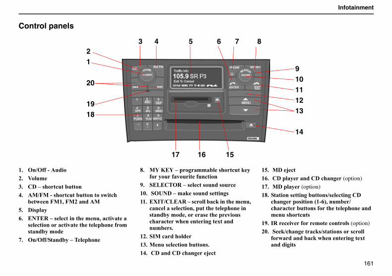
161
Infotainment
Control panels
($ ��1� �>������)$ :���'*$ "���� ���!���������+$ �0170�>� ���!������������� ���!��
�����70(,�70)������0-$ �� ����.$ ����%��� �!��������'��,��!��������
�!��������!���������������� �'� �������'��
/$ ��1� 1����������������
2$ 0A�9�A�������''���� ���!���#�� ������ ������� ��!����
4$ ��&�"��%��� �!�� ����� ��!(5$ ���C�����'�#� ����� ����� (($ �H��1"&��%��� !������!#�������'��,�
!��!���� �!����,������������������ �������'��,���� ��������� �!���!�������������6��������'� $
()$ ��0�!�������(*$ 0��� �!����������� $(+$ �"������"��!�����I!�
(-$ �0��I!�(.$ �"�����������"��!���� (option)
(/$ �0������ (option)
(2$ �������� ������������ 1 �!�����"��!������� ������;(>.<,���'�1!���!�������� � ����������������'��� ���!��
(4$ �%�!��� ��'���!����� (option)
)5$ ��#1!�������!# 1 ������ ��� !���� �����������!#������������6�����������
21
20
1918
3 4 5 6 7 8
910111213
14
17 16 15
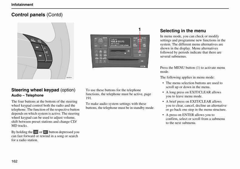
162
Infotainment
Control panels (Contd)
Steering wheel keypad (option)Audio – Telephone
The four buttons at the bottom of the steering wheel keypad control both the radio and the telephone. The function of the respective button depends on which system is active. The steering wheel keypad can be used to adjust volume, shift between preset stations and change CD/MD tracks.
By holding the or button depressed you can fast forward or rewind in a song or search for a radio station.
To use these buttons for the telephone functions, the telephone must be active, page 191.
To make audio system settings with these buttons, the telephone must be in standby mode.
Selecting in the menuIn menu mode, you can check or modify settings and programme new functions in the system. The different menu alternatives are shown in the display. Menu alternatives followed by periods indicate that there are several submenus.
Press the MENU button (1) to activate menu mode.
The following applies in menu mode:
• The menu selection buttons are used to scroll up or down in the menu.
• A long press on EXIT/CLEAR allows you to leave menu mode.
• A brief press on EXIT/CLEAR allows you to clear, cancel, decline an alternativeor go back one step in the menu structure.
• A press on ENTER allows you to confirm, select or scroll from a submenu to the next submenu.
1
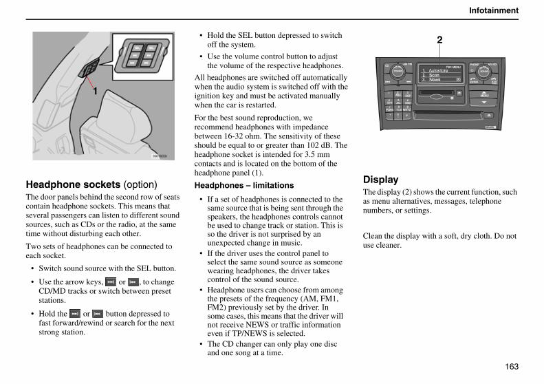
163
Infotainment
Headphone sockets (option)The door panels behind the second row of seats contain headphone sockets. This means that several passengers can listen to different sound sources, such as CDs or the radio, at the same time without disturbing each other.
Two sets of headphones can be connected to each socket.
• Switch sound source with the SEL button.
• Use the arrow keys, or , to change CD/MD tracks or switch between preset stations.
• Hold the or button depressed to fast forward/rewind or search for the next strong station.
• Hold the SEL button depressed to switch off the system.
• Use the volume control button to adjust the volume of the respective headphones.
All headphones are switched off automatically when the audio system is switched off with the ignition key and must be activated manually when the car is restarted.
For the best sound reproduction, we recommend headphones with impedance between 16-32 ohm. The sensitivity of these should be equal to or greater than 102 dB. The headphone socket is intended for 3.5 mm contacts and is located on the bottom of the headphone panel (1).
Headphones – limitations
• If a set of headphones is connected to the same source that is being sent through the speakers, the headphones controls cannot be used to change track or station. This is so the driver is not surprised by an unexpected change in music.
• If the driver uses the control panel to select the same sound source as someone wearing headphones, the driver takes control of the sound source.
• Headphone users can choose from among the presets of the frequency (AM, FM1, FM2) previously set by the driver. In some cases, this means that the driver will not receive NEWS or traffic information even if TP/NEWS is selected.
• The CD changer can only play one disc and one song at a time.
DisplayThe display (2) shows the current function, such as menu alternatives, messages, telephone numbers, or settings.
Clean the display with a soft, dry cloth. Do not use cleaner.
1
2
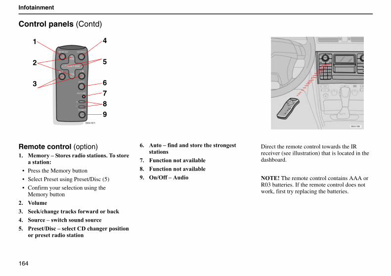
164
Infotainment
Control panels (Contd)
Remote control (option)($ 0'�������� ������ ������ $���� ���
�� �������
• Press the Memory button
• Select Preset using Preset/Disc (5)
• Confirm your selection using the Memory button
)$ :���'
*$ �#1!�������!# � ���������!#
+$ ���!��� ���!�� ����� ��!
-$ � �1�� !��� �!��"��!������� ��������� ������� ������
.$ ������� �������� ������ ���� �� ������
/$ 7��!�����������������
2$ 7��!�����������������
4$ ��1� ��������
Direct the remote control towards the IR receiver (see illustration) that is located in the dashboard.
������The remote control contains AAA or R03 batteries. If the remote control does not work, first try replacing the batteries.
1
2
3
4
5
6789
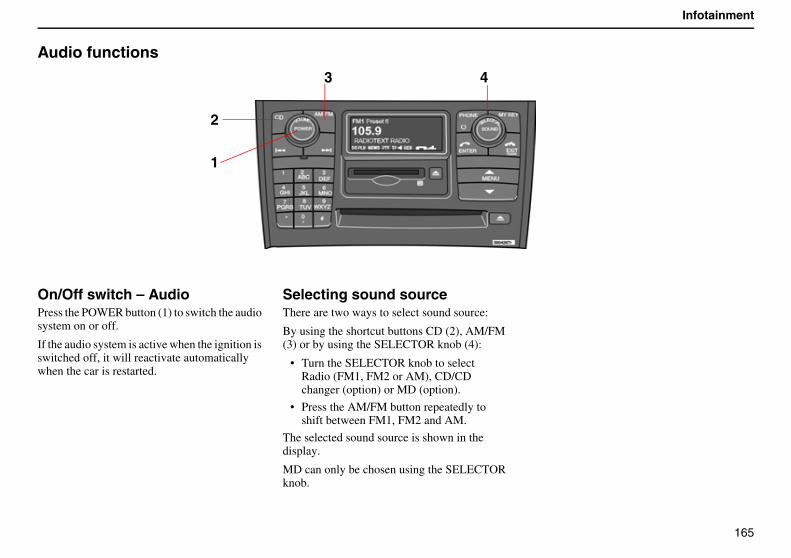
165
Infotainment
Audio functions
On/Off switch – AudioPress the POWER button (1) to switch the audio system on or off.
If the audio system is active when the ignition is switched off, it will reactivate automatically when the car is restarted.
Selecting sound sourceThere are two ways to select sound source:
By using the shortcut buttons CD (2), AM/FM (3) or by using the SELECTOR knob (4):
• Turn the SELECTOR knob to select Radio (FM1, FM2 or AM), CD/CD changer (option) or MD (option).
• Press the AM/FM button repeatedly to shift between FM1, FM2 and AM.
The selected sound source is shown in the display.
MD can only be chosen using the SELECTOR knob.
2
1
3 4
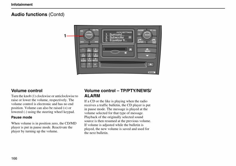
166
Infotainment
Audio functions (Contd)
Volume controlTurn the knob (1) clockwise or anticlockwise to raise or lower the volume, respectively. The volume control is electronic and has no end position. Volume can also be raised (+) or lowered (-) using the steering wheel keypad.
Pause mode
When volume is in position zero, the CD/MD player is put in pause mode. Reactivate the player by turning up the volume.
Volume control – TP/PTY/NEWS/ALARMIf a CD or the like is playing when the radio receives a traffic bulletin, the CD player is put in pause mode. The message is played at the volume selected for that type of message. Playback of the originally selected sound source is then resumed at the previous volume. If volume is adjusted while the bulletin is played, the new volume is saved and used for the next bulletin.
1
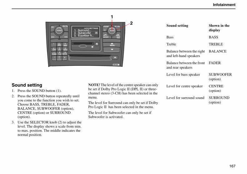
167
Infotainment
Sound setting1. Press the SOUND button (1).
2. Press the SOUND button repeatedly until you come to the function you wish to set. Choose BASS, TREBLE, FADER, BALANCE, SUBWOOFER (option), CENTRE (option) or SURROUND (option).
3. Use the SELECTOR knob (2) to adjust the level. The display shows a scale from min. to max. position. The middle indicates the normal position.
������The level of the centre speaker can only be set if Dolby Pro Logic II (DPL II) or three-channel stereo (3-CH) has been selected in the menu.
The level for Surround can only be set if Dolby Pro Logic II �has been selected in the menu.�
The level for Subwoofer can only be set if Subwoofer is activated.
������ ����� �������������� ����
Bass BASS
Treble TREBLE
Balance between the right and left-hand speakers
BALANCE
Balance between the front and rear speakers
FADER
Level for bass speaker SUBWOOFER(option)
Level for centre speaker CENTRE(option)
Level for surround sound SURROUND(option)
12
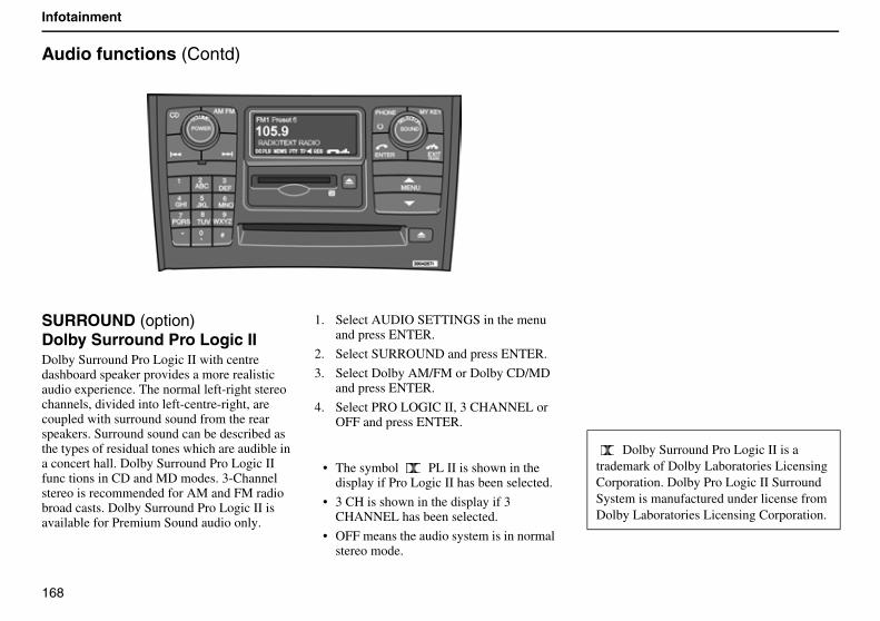
168
Infotainment
Audio functions (Contd)
SURROUND (option) Dolby Surround Pro Logic II Dolby Surround Pro Logic II with centre dashboard speaker provides a more realistic audio experience. The normal left-right stereo channels, divided into left-centre-right, are coupled with surround sound from the rear speakers. Surround sound can be described as the types of residual tones which are audible in a concert hall. Dolby Surround Pro Logic II func tions in CD and MD modes. 3-Channel stereo is recommended for AM and FM radio broad casts. Dolby Surround Pro Logic II is available for Premium Sound audio only.
1. Select AUDIO SETTINGS in the menu and press ENTER.
2. Select SURROUND and press ENTER.
3. Select Dolby AM/FM or Dolby CD/MD and press ENTER.
4. Select PRO LOGIC II, 3 CHANNEL or OFF and press ENTER.
• The symbol PL II is shown in the display if Pro Logic II has been selected.
• 3 CH is shown in the display if 3 CHANNEL has been selected.
• OFF means the audio system is in normal stereo mode.
Dolby Surround Pro Logic II is a trademark of Dolby Laboratories Licensing Corporation. Dolby Pro Logic II Surround System is manufactured under license from Dolby Laboratories Licensing Corporation.
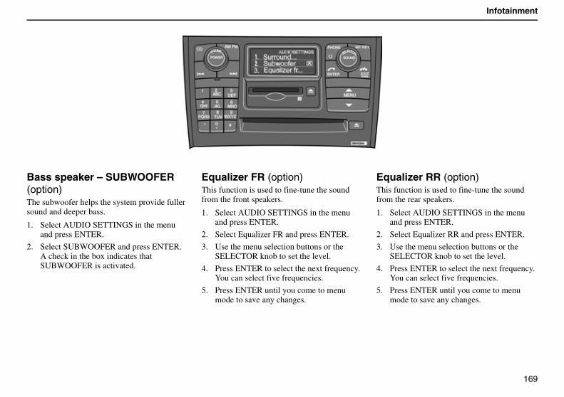
169
Infotainment
Bass speaker – SUBWOOFER (option)The subwoofer helps the system provide fuller sound and deeper bass.
1. Select AUDIO SETTINGS in the menu and press ENTER.
2. Select SUBWOOFER and press ENTER. A check in the box indicates that SUBWOOFER is activated.
Equalizer FR (option)This function is used to fine-tune the sound from the front speakers.
1. Select AUDIO SETTINGS in the menu and press ENTER.
2. Select Equalizer FR and press ENTER.
3. Use the menu selection buttons or the SELECTOR knob to set the level.
4. Press ENTER to select the next frequency. You can select five frequencies.
5. Press ENTER until you come to menu mode to save any changes.
Equalizer RR (option)This function is used to fine-tune the sound from the rear speakers.
1. Select AUDIO SETTINGS in the menu and press ENTER.
2. Select Equalizer RR and press ENTER.
3. Use the menu selection buttons or the SELECTOR knob to set the level.
4. Press ENTER to select the next frequency. You can select five frequencies.
5. Press ENTER until you come to menu mode to save any changes.
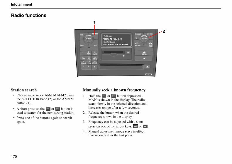
170
Infotainment
Radio functions
�������� �!�• Choose radio mode AM/FM1/FM2 using
the SELECTOR knob (2) or the AM/FM button (1).
• A short press on the or button is used to search for the next strong station.
• Press one of the buttons again to search again.
0�������� #���#����� J��!�1. Hold the or button depressed.
MAN is shown in the display. The radio scans slowly in the selected direction and increases tempo after a few seconds.
2. Release the button when the desired frequency shows in the display.
3. Frequency can be adjusted with a short press on one of the arrow keys, or .
4. Manual adjustment mode stays in effect five seconds after the last press.
1
2
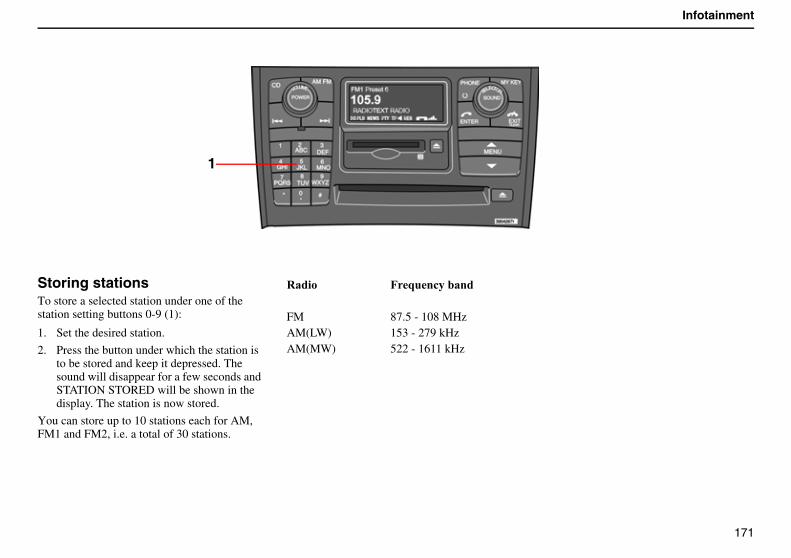
171
Infotainment
Storing stationsTo store a selected station under one of the station setting buttons 0-9 (1):
1. Set the desired station.
2. Press the button under which the station is to be stored and keep it depressed. The sound will disappear for a few seconds and STATION STORED will be shown in the display. The station is now stored.
You can store up to 10 stations each for AM, FM1 and FM2, i.e. a total of 30 stations.
%���� 7J��!������
FM 87.5 - 108 MHzAM(LW) 153 - 279 kHzAM(MW) 522 - 1611 kHz
1
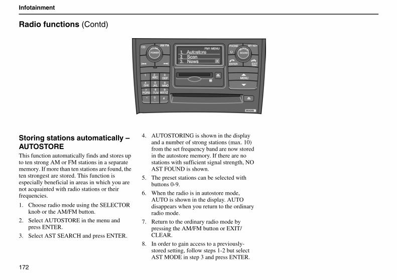
172
Infotainment
Radio functions (Contd)
Storing stations automatically – AUTOSTOREThis function automatically finds and stores up to ten strong AM or FM stations in a separate memory. If more than ten stations are found, the ten strongest are stored. This function is especially beneficial in areas in which you are not acquainted with radio stations or their frequencies.
1. Choose radio mode using the SELECTOR knob or the AM/FM button.
2. Select AUTOSTORE in the menu and press ENTER.
3. Select AST SEARCH and press ENTER.
4. AUTOSTORING is shown in the display and a number of strong stations (max. 10) from the set frequency band are now stored in the autostore memory. If there are no stations with sufficient signal strength, NO AST FOUND is shown.
5. The preset stations can be selected with buttons 0-9.
6. When the radio is in autostore mode, AUTO is shown in the display. AUTO disappears when you return to the ordinary radio mode.
7. Return to the ordinary radio mode by pressing the AM/FM button or EXIT/CLEAR.
8. In order to gain access to a previously-stored setting, follow steps 1-2 but select AST MODE in step 3 and press ENTER.
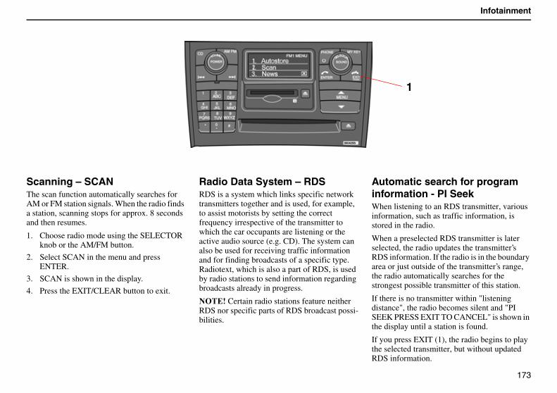
173
Infotainment
Scanning – SCAN The scan function automatically searches for AM or FM station signals. When the radio finds a station, scanning stops for approx. 8 seconds and then resumes.
1. Choose radio mode using the SELECTOR knob or the AM/FM button.
2. Select SCAN in the menu and press ENTER.
3. SCAN is shown in the display.
4. Press the EXIT/CLEAR button to exit.
Radio Data System – RDSRDS is a system which links specific network transmitters together and is used, for example, to assist motorists by setting the correct frequency irrespective of the transmitter to which the car occupants are listening or the active audio source (e.g. CD). The system can also be used for receiving traffic information and for finding broadcasts of a specific type. Radiotext, which is also a part of RDS, is used by radio stations to send information regarding broadcasts already in progress.
������Certain radio stations feature neither RDS nor specific parts of RDS broadcast possi-bilities.
Automatic search for program information - PI SeekWhen listening to an RDS transmitter, various information, such as traffic information, is stored in the radio.
When a preselected RDS transmitter is later selected, the radio updates the transmitter’s RDS information. If the radio is in the boundary area or just outside of the transmitter’s range, the radio automatically searches for the strongest possible transmitter of this station.
If there is no transmitter within "listening distance", the radio becomes silent and "PI SEEK PRESS EXIT TO CANCEL" is shown in the display until a station is found.
If you press EXIT (1), the radio begins to play the selected transmitter, but without updated RDS information.
1
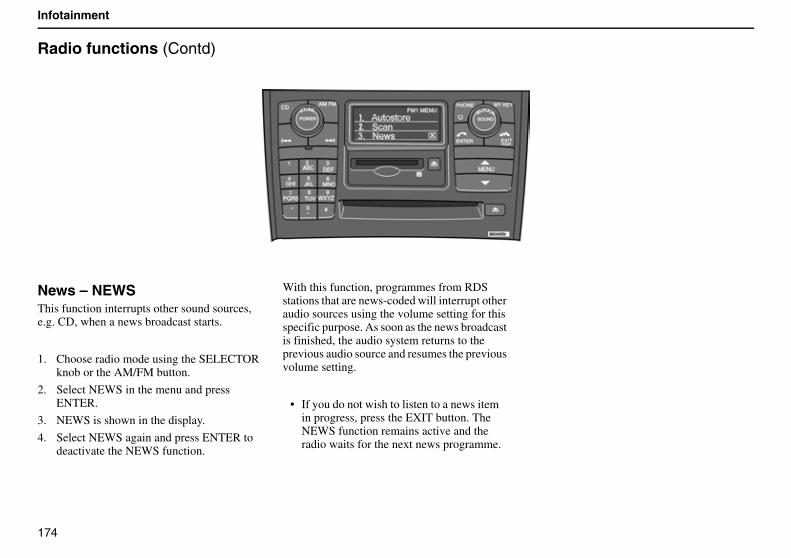
174
Infotainment
Radio functions (Contd)
News – NEWSThis function interrupts other sound sources, e.g. CD, when a news broadcast starts.
1. Choose radio mode using the SELECTOR knob or the AM/FM button.
2. Select NEWS in the menu and press ENTER.
3. NEWS is shown in the display.
4. Select NEWS again and press ENTER to deactivate the NEWS function.
With this function, programmes from RDS stations that are news-coded will interrupt other audio sources using the volume setting for this specific purpose. As soon as the news broadcast is finished, the audio system returns to the previous audio source and resumes the previous volume setting.
• If you do not wish to listen to a news item in progress, press the EXIT button. The NEWS function remains active and the radio waits for the next news programme.
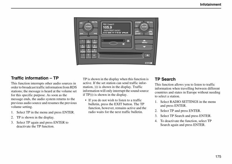
175
Infotainment
Traffic information – TPThis function interrupts other audio sources in order to broadcast traffic information from RDS stations; the message is heard at the volume set for this specific purpose. As soon as the message ends, the audio system returns to the previous audio source and resumes the previous volume setting.
1. Select TP in the menu and press ENTER.
2. TP is shown in the display.
3. Select TP again and press ENTER to deactivate the TP function.
TP is shown in the display when this function is active. If the set station can send traffic infor-mation, ))) is shown in the display. Traffic information will only interrupt the sound source if TP))) is shown in the display.
• If you do not wish to listen to a traffic bulletin, press the EXIT button. The TP function, however, remains active and the radio waits for the next traffic bulletin.
TP SearchThis function allows you to listen to traffic information when travelling between different countries and states in Europe without needing to select a station.
1. Select RADIO SETTINGS in the menu and press ENTER.
2. Select TP and press ENTER.
3. Select TP Search and press ENTER.
4. To deactivate the function, select TP Search again and press ENTER.
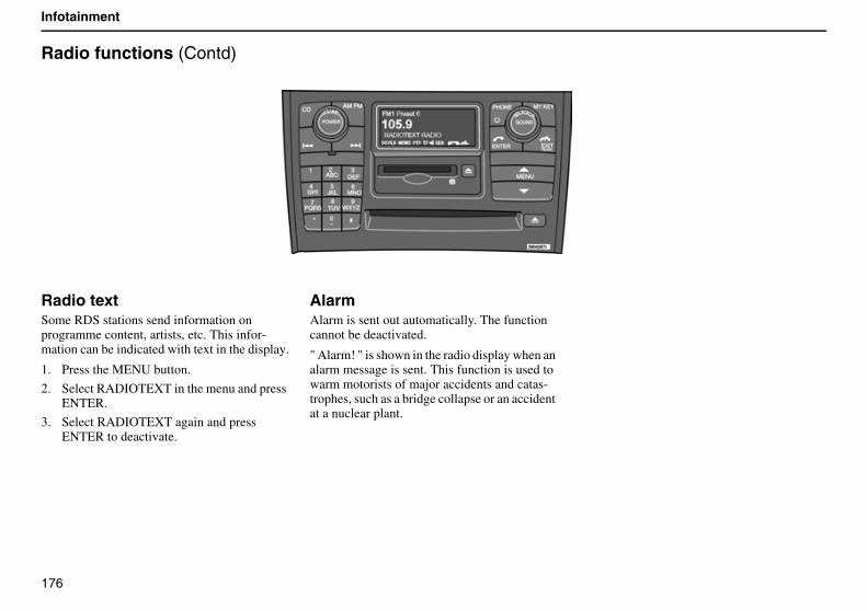
176
Infotainment
Radio functions (Contd)
Radio textSome RDS stations send information on programme content, artists, etc. This infor-mation can be indicated with text in the display.
1. Press the MENU button.
2. Select RADIOTEXT in the menu and press ENTER.
3. Select RADIOTEXT again and press ENTER to deactivate.
AlarmAlarm is sent out automatically. The function cannot be deactivated.
" Alarm! " is shown in the radio display when an alarm message is sent. This function is used to warm motorists of major accidents and catas-trophes, such as a bridge collapse or an accident at a nuclear plant.
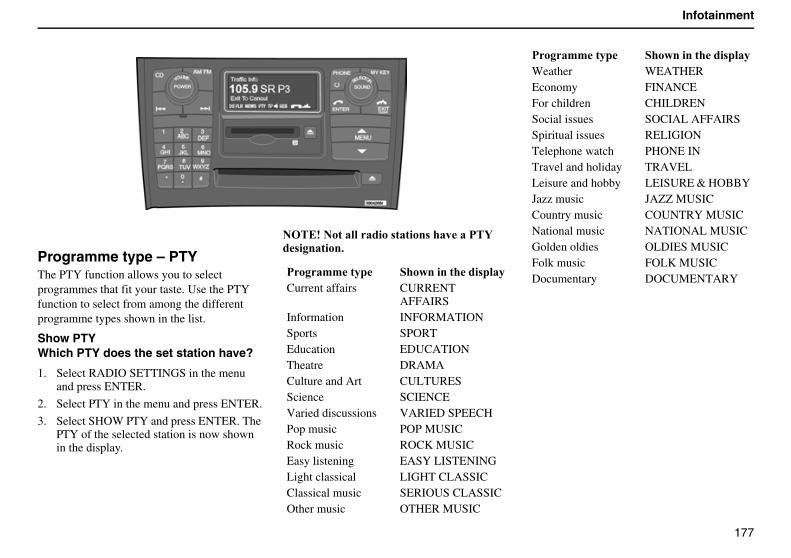
177
Infotainment
Programme type – PTYThe PTY function allows you to select programmes that fit your taste. Use the PTY function to select from among the different programme types shown in the list.
Show PTYWhich PTY does the set station have?
1. Select RADIO SETTINGS in the menu and press ENTER.
2. Select PTY in the menu and press ENTER.
3. Select SHOW PTY and press ENTER. The PTY of the selected station is now shown in the display.
������������������� ������ ���������A�� ��������$
����''���� �������������� ����Current affairs CURRENT
AFFAIRSInformation INFORMATIONSports SPORTEducation EDUCATIONTheatre DRAMACulture and Art CULTURESScience SCIENCEVaried discussions VARIED SPEECHPop music POP MUSICRock music ROCK MUSICEasy listening EASY LISTENINGLight classical LIGHT CLASSICClassical music SERIOUS CLASSICOther music OTHER MUSIC
Weather WEATHEREconomy FINANCEFor children CHILDRENSocial issues SOCIAL AFFAIRSSpiritual issues RELIGIONTelephone watch PHONE INTravel and holiday TRAVELLeisure and hobby LEISURE & HOBBYJazz music JAZZ MUSICCountry music COUNTRY MUSICNational music NATIONAL MUSICGolden oldies OLDIES MUSICFolk music FOLK MUSICDocumentary DOCUMENTARY
����''���� �������������� ����
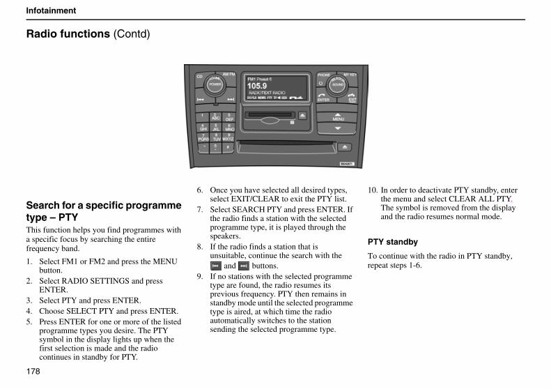
178
Infotainment
Radio functions (Contd)
Search for a specific programme type – PTYThis function helps you find programmes with a specific focus by searching the entire frequency band.
1. Select FM1 or FM2 and press the MENU button.
2. Select RADIO SETTINGS and press ENTER.
3. Select PTY and press ENTER.4. Choose SELECT PTY and press ENTER.5. Press ENTER for one or more of the listed
programme types you desire. The PTY symbol in the display lights up when the first selection is made and the radio continues in standby for PTY.
6. Once you have selected all desired types, select EXIT/CLEAR to exit the PTY list.
7. Select SEARCH PTY and press ENTER. If the radio finds a station with the selected programme type, it is played through the speakers.
8. If the radio finds a station that is unsuitable, continue the search with the
and buttons.9. If no stations with the selected programme
type are found, the radio resumes its previous frequency. PTY then remains in standby mode until the selected programme type is aired, at which time the radio automatically switches to the station sending the selected programme type.
10. In order to deactivate PTY standby, enter the menu and select CLEAR ALL PTY. The symbol is removed from the display and the radio resumes normal mode.
PTY standby
To continue with the radio in PTY standby, repeat steps 1-6.
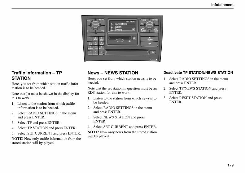
179
Infotainment
Traffic information – TP STATIONHere, you set from which station traffic infor-mation is to be heeded.
Note that ))) must be shown in the display for this to work.
1. Listen to the station from which traffic information is to be heeded.
2. Select RADIO SETTINGS in the menu and press ENTER.
3. Select TP and press ENTER.
4. Select TP STATION and press ENTER.
5. Select SET CURRENT and press ENTER.
������Now only traffic information from the stored station will by played.
News – NEWS STATIONHere, you set from which station news is to be heeded.
Note that the set station in question must be an RDS station for this to work.
1. Listen to the station from which news is to be heeded.
2. Select RADIO SETTINGS in the menu and press ENTER.
3. Select NEWS STATION and press ENTER.
4. Select SET CURRENT and press ENTER.
������Now only news from the stored station will by played.
Deactivate TP STATION/NEWS STATION
1. Select RADIO SETTINGS in the menu and press ENTER.
2. Select TP/NEWS STATION and press ENTER.
3. Select RESET STATION and press ENTER.
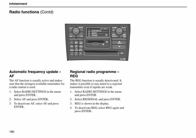
180
Infotainment
Radio functions (Contd)
Automatic frequency update – AFThe AF function is usually active and makes sure that the strongest available transmitter for a radio station is used.
1. Select RADIO SETTINGS in the menu and press ENTER.
2. Select AF and press ENTER.
3. To deactivate AF, select AF and press ENTER.
Regional radio programme – REGThe REG function is usually deactivated. It makes it possible to stay tuned to a regional transmitter even if signals are weak.
1. Select RADIO SETTINGS in the menu and press ENTER.
2. Select REGIONAL and press ENTER.
3. REG is shown in the display.
4. To deactivate REG, select REG again and press ENTER.
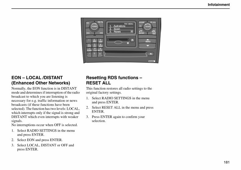
181
Infotainment
EON – LOCAL /DISTANT (Enhanced Other Networks)Normally, the EON function is in DISTANT mode and determines if interruption of the radio broadcast to which you are listening is necessary for e.g. traffic information or news broadcasts (if these functions have been selected). The function has two levels: LOCAL, which interrupts only if the signal is strong and DISTANT which even interrupts with weaker signals.No interruptions occur when OFF is selected.
1. Select RADIO SETTINGS in the menu and press ENTER.
2. Select EON and press ENTER.
3. Select LOCAL, DISTANT or OFF and press ENTER.
Resetting RDS functions – RESET ALLThis function restores all radio settings to the original factory settings.
1. Select RADIO SETTINGS in the menu and press ENTER.
2. Select RESET ALL in the menu and press ENTER.
3. Press ENTER again to confirm your selection.
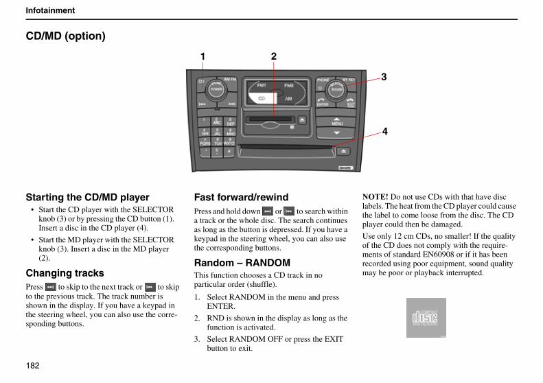
182
Infotainment
CD/MD (option)
Starting the CD/MD player• Start the CD player with the SELECTOR
knob (3) or by pressing the CD button (1). Insert a disc in the CD player (4).
• Start the MD player with the SELECTOR knob (3). Insert a disc in the MD player (2).
Changing tracksPress to skip to the next track or to skip to the previous track. The track number is shown in the display. If you have a keypad in the steering wheel, you can also use the corre-sponding buttons.
Fast forward/rewindPress and hold down or to search within a track or the whole disc. The search continues as long as the button is depressed. If you have a keypad in the steering wheel, you can also use the corresponding buttons.
Random – RANDOMThis function chooses a CD track in no particular order (shuffle).
1. Select RANDOM in the menu and press ENTER.
2. RND is shown in the display as long as the function is activated.
3. Select RANDOM OFF or press the EXIT button to exit.
������Do not use CDs with that have disc labels. The heat from the CD player could cause the label to come loose from the disc. The CD player could then be damaged.
Use only 12 cm CDs, no smaller! If the quality of the CD does not comply with the require-ments of standard EN60908 or if it has been recorded using poor equipment, sound quality may be poor or playback interrupted.
3
1
4
2
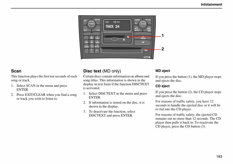
183
Infotainment
ScanThis function plays the first ten seconds of each song or track.
1. Select SCAN in the menu and press ENTER.
2. Press EXIT/CLEAR when you find a song or track you wish to listen to.
Disc text (MD only)Certain discs contain information on album and song titles. This information is shown in the display in text form if the function DISCTEXT is activated.
1. Select DISCTEXT in the menu and press ENTER.
2. If information is stored on the disc, it is shown in the display.
3. To deactivate the function, select DISCTEXT and press ENTER.
MD eject
If you press the button (1), the MD player stops and ejects the disc.
CD eject
If you press the button (2), the CD player stops and ejects the disc.
For reasons of traffic safety, you have 12 seconds to handle the ejected disc or it will be re-fed into the CD player.
For reasons of traffic safety, the ejected CD remains out no more than 12 seconds. The CD player then pulls it back in. To reactivate the CD player, press the CD button (3).
1
2
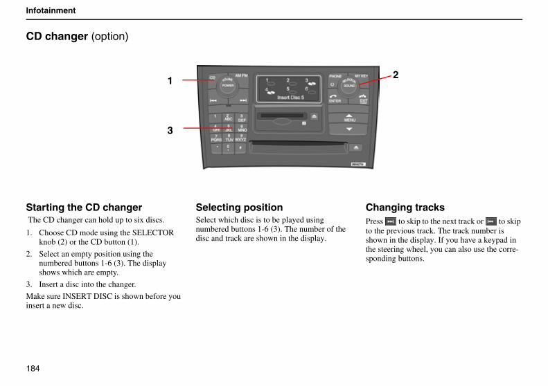
184
Infotainment
CD changer (option)
Starting the CD changer The CD changer can hold up to six discs.
1. Choose CD mode using the SELECTOR knob (2) or the CD button (1).
2. Select an empty position using the numbered buttons 1-6 (3). The display shows which are empty.
3. Insert a disc into the changer.
Make sure INSERT DISC is shown before you insert a new disc.
Selecting positionSelect which disc is to be played using numbered buttons 1-6 (3). The number of the disc and track are shown in the display.
Changing tracksPress to skip to the next track or to skip to the previous track. The track number is shown in the display. If you have a keypad in the steering wheel, you can also use the corre-sponding buttons.
1
3
2
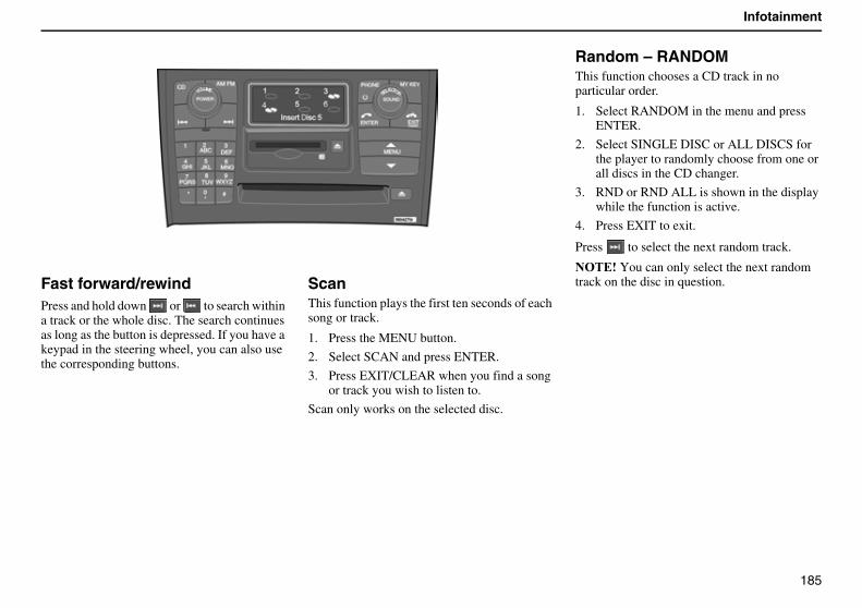
185
Infotainment
Fast forward/rewindPress and hold down or to search within a track or the whole disc. The search continues as long as the button is depressed. If you have a keypad in the steering wheel, you can also use the corresponding buttons.
ScanThis function plays the first ten seconds of each song or track.
1. Press the MENU button.
2. Select SCAN and press ENTER.
3. Press EXIT/CLEAR when you find a song or track you wish to listen to.
Scan only works on the selected disc.
Random – RANDOMThis function chooses a CD track in no particular order.
1. Select RANDOM in the menu and press ENTER.
2. Select SINGLE DISC or ALL DISCS for the player to randomly choose from one or all discs in the CD changer.
3. RND or RND ALL is shown in the display while the function is active.
4. Press EXIT to exit.
Press to select the next random track.
������You can only select the next random track on the disc in question.
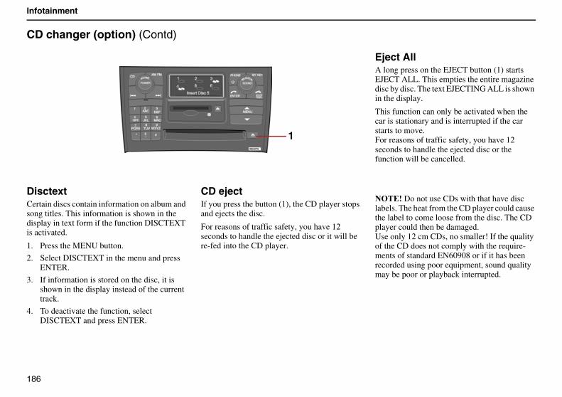
186
Infotainment
CD changer (option) (Contd)
DisctextCertain discs contain information on album and song titles. This information is shown in the display in text form if the function DISCTEXT is activated.
1. Press the MENU button.
2. Select DISCTEXT in the menu and press ENTER.
3. If information is stored on the disc, it is shown in the display instead of the current track.
4. To deactivate the function, select DISCTEXT and press ENTER.
CD ejectIf you press the button (1), the CD player stops and ejects the disc.
For reasons of traffic safety, you have 12 seconds to handle the ejected disc or it will be re-fed into the CD player.
Eject AllA long press on the EJECT button (1) starts EJECT ALL. This empties the entire magazine disc by disc. The text EJECTING ALL is shown in the display.
This function can only be activated when the car is stationary and is interrupted if the car starts to move.For reasons of traffic safety, you have 12 seconds to handle the ejected disc or the function will be cancelled.
������Do not use CDs with that have disc labels. The heat from the CD player could cause the label to come loose from the disc. The CD player could then be damaged.Use only 12 cm CDs, no smaller! If the quality of the CD does not comply with the require-ments of standard EN60908 or if it has been recorded using poor equipment, sound quality may be poor or playback interrupted.
1
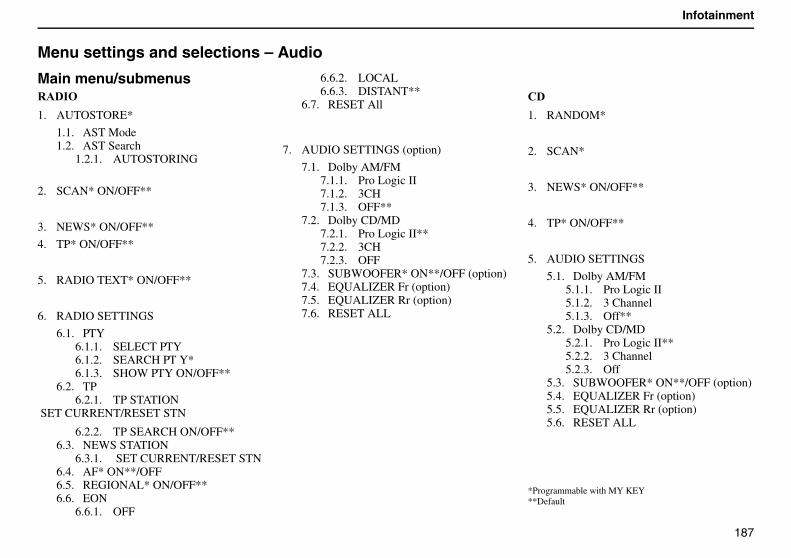
187
Infotainment
Menu settings and selections – Audio
Main menu/submenus%����
1. AUTOSTORE*
1.1. AST Mode1.2. AST Search
1.2.1. AUTOSTORING
2. SCAN* ON/OFF**
3. NEWS* ON/OFF**
4. TP* ON/OFF**
5. RADIO TEXT* ON/OFF**
6. RADIO SETTINGS
6.1. PTY6.1.1. SELECT PTY 6.1.2. SEARCH PT Y*6.1.3. SHOW PTY ON/OFF**
6.2. TP6.2.1. TP STATION
SET CURRENT/RESET STN
6.2.2. TP SEARCH ON/OFF**6.3. NEWS STATION
6.3.1. SET CURRENT/RESET STN6.4. AF* ON**/OFF6.5. REGIONAL* ON/OFF**6.6. EON
6.6.1. OFF
6.6.2. LOCAL6.6.3. DISTANT**
6.7. RESET All
7. AUDIO SETTINGS (option)
7.1. Dolby AM/FM7.1.1. Pro Logic II7.1.2. 3CH7.1.3. OFF**
7.2. Dolby CD/MD7.2.1. Pro Logic II**7.2.2. 3CH7.2.3. OFF
7.3. SUBWOOFER* ON**/OFF (option)7.4. EQUALIZER Fr (option)7.5. EQUALIZER Rr (option)7.6. RESET ALL
"�
1. RANDOM*
2. SCAN*
3. NEWS* ON/OFF**
4. TP* ON/OFF**
5. AUDIO SETTINGS
5.1. Dolby AM/FM5.1.1. Pro Logic II5.1.2. 3 Channel5.1.3. Off**
5.2. Dolby CD/MD5.2.1. Pro Logic II**5.2.2. 3 Channel5.2.3. Off
5.3. SUBWOOFER* ON**/OFF (option)5.4. EQUALIZER Fr (option)5.5. EQUALIZER Rr (option)5.6. RESET ALL
*Programmable with MY KEY**Default
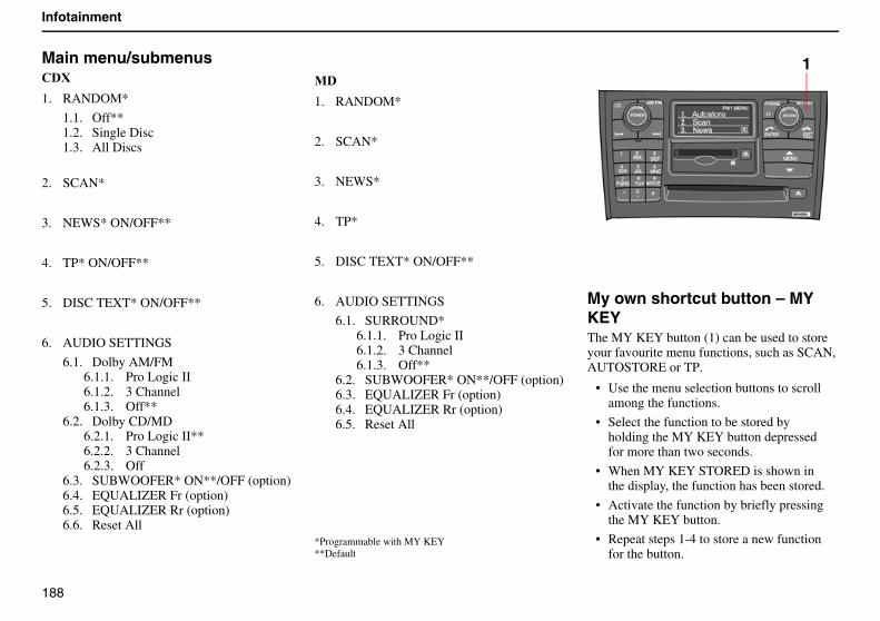
188
Infotainment
Main menu/submenus"�H
1. RANDOM*
1.1. Off**1.2. Single Disc1.3. All Discs
2. SCAN*
3. NEWS* ON/OFF**
4. TP* ON/OFF**
5. DISC TEXT* ON/OFF**
6. AUDIO SETTINGS
6.1. Dolby AM/FM6.1.1. Pro Logic II6.1.2. 3 Channel6.1.3. Off**
6.2. Dolby CD/MD6.2.1. Pro Logic II**6.2.2. 3 Channel6.2.3. Off
6.3. SUBWOOFER* ON**/OFF (option)6.4. EQUALIZER Fr (option)6.5. EQUALIZER Rr (option)6.6. Reset All
0�
1. RANDOM*
2. SCAN*
3. NEWS*
4. TP*
5. DISC TEXT* ON/OFF**
6. AUDIO SETTINGS
6.1. SURROUND*6.1.1. Pro Logic II6.1.2. 3 Channel6.1.3. Off**
6.2. SUBWOOFER* ON**/OFF (option)6.3. EQUALIZER Fr (option)6.4. EQUALIZER Rr (option)6.5. Reset All
*Programmable with MY KEY**Default
My own shortcut button – MY KEYThe MY KEY button (1) can be used to store your favourite menu functions, such as SCAN, AUTOSTORE or TP.
• Use the menu selection buttons to scroll among the functions.
• Select the function to be stored by holding the MY KEY button depressed for more than two seconds.
• When MY KEY STORED is shown in the display, the function has been stored.
• Activate the function by briefly pressing the MY KEY button.
• Repeat steps 1-4 to store a new function for the button.
1
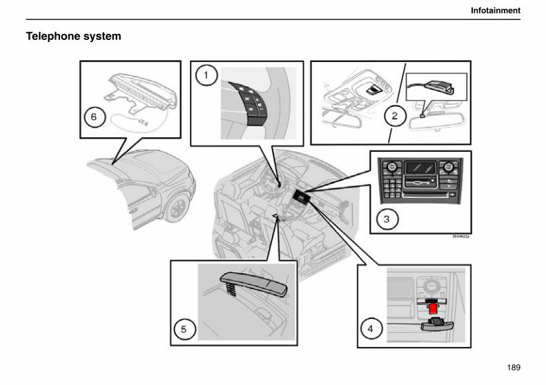
189
Infotainment
Telephone system
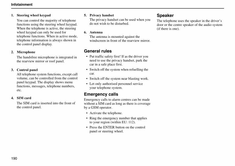
190
Infotainment
($ ����������#����
You can control the majority of telephone functions using the steering wheel keypad.When the telephone is active, the steering wheel keypad can only be used for telephone functions. When in active mode, telephone information is always shown in the control panel display.
)$ 0�!�����
The handsfree microphone is integrated in the rearview mirror or roof panel.
*$ "����������All telephone system functions, except call volume, can be controlled from the control panel keypad. The display shows menu functions, messages, telephone numbers, etc.
+$ ��0�!��
The SIM card is inserted into the front of the control panel.
-$ ����!������ �The privacy handset can be used when you do not wish to be disturbed.
.$ ������The antenna is mounted against the windscreen in front of the rearview mirror.
General rules• Put traffic safety first! If as the driver you
need to use the privacy handset, park the car in a safe place first.
• Switch off the system when refuelling the car.
• Switch off the system near blasting work.
• Let only authorised personnel service your telephone system.
Emergency callsEmergency calls to alarm centres can be made without a SIM card as long as there is coverage by a GSM operator.
• Activate the telephone.
• Ring the emergency number that applies to your region (within EU: 112).
• Press the ENTER button on the control panel or steering wheel.
SpeakerThe telephone uses the speaker in the driver’s door or the centre speaker of the audio system (if there is one).
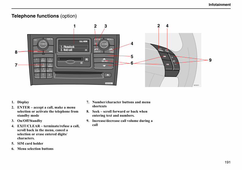
191
Infotainment
Telephone functions (option)
($ �� ����
)$ ����%����!!�����!���,�'�#���'��� �!��������!���������������� �'� �������'��
*$ ��1� 1�������
+$ �H��1"&��%����'����1 � ���!���,� !������!#�������'��,�!��!���� �!�������� ���������� 1!���!� $
-$ ��0�!�������
.$ 0��� �!�����������
/$ ��'�1!���!�������� �����'��� ���!��
2$ �#��� !���� ���������!#������������6��������'� $
4$ ��!� 1�!� �!��������'���������!���
4
56
1 2 3
8
79
2 4
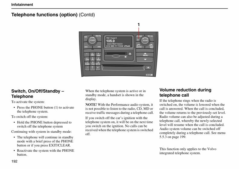
192
Infotainment
Telephone functions (option) (Contd)
Switch, On/Off/Standby – TelephoneTo activate the system:
• Press the PHONE button (1) to activate the telephone system.
To switch off the system:
• Hold the PHONE button depressed to switch off the telephone system
Continuing with system in standby mode:
• The telephone will continue in standby mode with a brief press of the PHONE button or if you press EXIT/CLEAR.
• Reactivate the system with the PHONE button.
When the telephone system is active or in standby mode, a handset is shown in the display.
������With the Performance audio system, it is not possible to listen to the radio, CD, MD or receive traffic messages during a telephone call.
If you switch off the car’s ignition with the telephone system on, it will be on the next time you switch on the ignition. No calls can be received when the telephone system is switched off.
Volume reduction during telephone callIf the telephone rings when the radio is switched on, the volume is lowered when the call is answered. When the call is concluded, the volume returns to the previously-set level. Radio volume can also be adjusted during a telephone call, whereby the newly-selected level will resume when the call is concluded. Audio system volume can be switched off completely during a telephone call. See menu 5.5.3 on page 199.
This function only applies to the Volvo integrated telephone system.
1
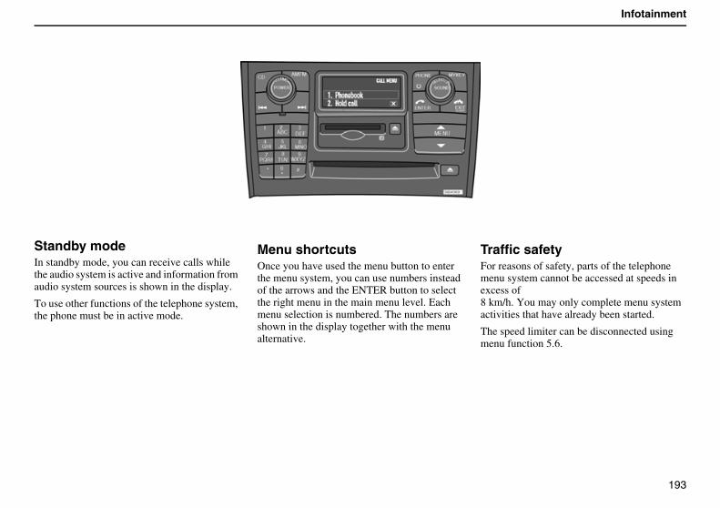
193
Infotainment
Standby modeIn standby mode, you can receive calls while the audio system is active and information from audio system sources is shown in the display.
To use other functions of the telephone system, the phone must be in active mode.
Menu shortcutsOnce you have used the menu button to enter the menu system, you can use numbers instead of the arrows and the ENTER button to select the right menu in the main menu level. Each menu selection is numbered. The numbers are shown in the display together with the menu alternative.
Traffic safetyFor reasons of safety, parts of the telephone menu system cannot be accessed at speeds in excess of8 km/h. You may only complete menu system activities that have already been started.
The speed limiter can be disconnected using menu function 5.6.
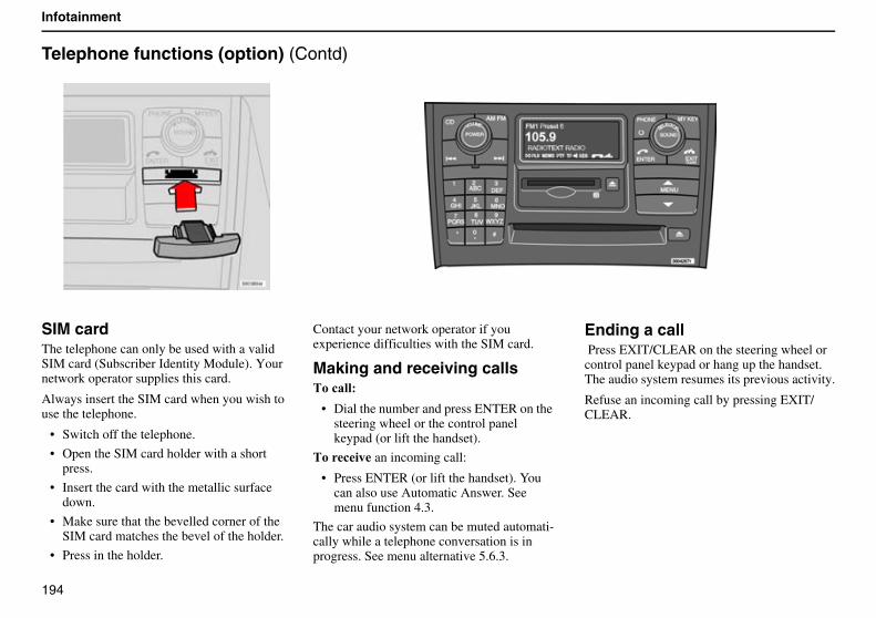
194
Infotainment
Telephone functions (option) (Contd)
SIM cardThe telephone can only be used with a valid SIM card (Subscriber Identity Module). Your network operator supplies this card.
Always insert the SIM card when you wish to use the telephone.
• Switch off the telephone.
• Open the SIM card holder with a short press.
• Insert the card with the metallic surface down.
• Make sure that the bevelled corner of the SIM card matches the bevel of the holder.
• Press in the holder.
Contact your network operator if you experience difficulties with the SIM card.
Making and receiving calls���!����
• Dial the number and press ENTER on the steering wheel or the control panel keypad (or lift the handset).
���!�� an incoming call:
• Press ENTER (or lift the handset). You can also use Automatic Answer. See menu function 4.3.
The car audio system can be muted automati-cally while a telephone conversation is in progress. See menu alternative 5.6.3.
Ending a call Press EXIT/CLEAR on the steering wheel or control panel keypad or hang up the handset. The audio system resumes its previous activity.
Refuse an incoming call by pressing EXIT/CLEAR.
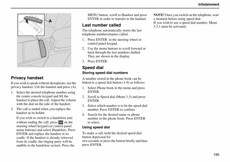
195
Infotainment
Privacy handsetIf you wish to speak without disruptions, use the privacy handset. Lift the handset and press (A).
1. Select the desired telephone number using the centre console keypad and lift the handset to place the call. Adjust the volume with the dial on the side of the handset.
2. The call is ended when you replace the handset in its holder.
If you wish to switch to a handsfree unit without ending the call: press on the steering wheel keypad (or control panel menu buttons) and select Handsfree. Press ENTER and replace the handset in its cradle. If the handset is already removed from its cradle, the ringing party will be audible in the handsfree system. Press the
MENU button, scroll to Handset and press ENTER in order to transfer to the handset.
Last number called The telephone automatically stores the last telephone numbers/names called.
1. Press ENTER in the steering wheel or control panel keypad.
2. Use the menu buttons to scroll forward or back through the last numbers dialled. They are shown in the display.
3. Press ENTER.
Speed dialStoring speed dial numbers
A number stored in the phone book can be linked to a speed dial button (1-9) as follows:
1. Select Phone book in the menu and press ENTER.
2. Scroll to Speed dial (Menu 3.3) and press ENTER.
3. Select which number is to be the speed dial number. Press ENTER to confirm.
4. Search for the desired name or phone number in the phone book. Press ENTER to select.
Using speed dial
To make a call, hold the desired speed dial button depressed fortwo seconds or press the button briefly and then press ENTER.
������Once you switch on the telephone, wait a moment before using speed dial.If you wish to use a speed dial number, Menu 3.3.1 must be activated.
A
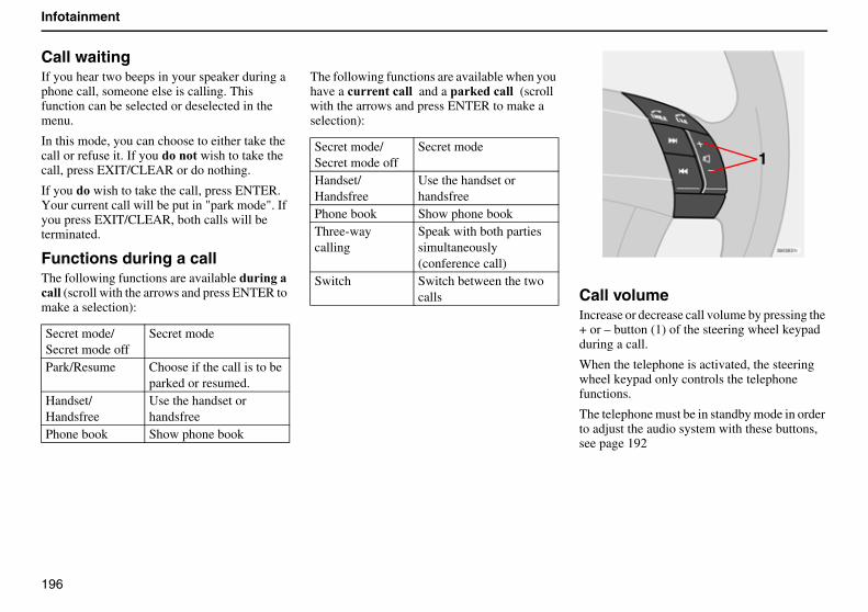
196
Infotainment
Call waitingIf you hear two beeps in your speaker during a phone call, someone else is calling. This function can be selected or deselected in the menu.
In this mode, you can choose to either take the call or refuse it. If you������� wish to take the call, press EXIT/CLEAR or do nothing.
If you �� wish to take the call, press ENTER. Your current call will be put in "park mode". If you press EXIT/CLEAR, both calls will be terminated.
Functions during a callThe following functions are available ��������!��� (scroll with the arrows and press ENTER to make a selection):
The following functions are available when you have a !����!���� and a ��#��!���� (scroll with the arrows and press ENTER to make a selection):
Call volumeIncrease or decrease call volume by pressing the + or – button (1) of the steering wheel keypad during a call.
When the telephone is activated, the steering wheel keypad only controls the telephone functions.
The telephone must be in standby mode in order to adjust the audio system with these buttons, see page 192
Secret mode/Secret mode off
Secret mode
Park/Resume Choose if the call is to be parked or resumed.
Handset/Handsfree
Use the handset or handsfree
Phone book Show phone book
Secret mode/Secret mode off
Secret mode
Handset/Handsfree
Use the handset or handsfree
Phone book Show phone bookThree-way calling
Speak with both parties simultaneously (conference call)
Switch Switch between the two calls
1
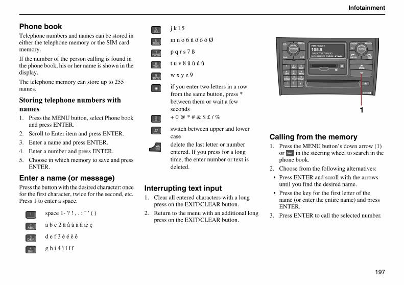
197
Infotainment
Phone bookTelephone numbers and names can be stored in either the telephone memory or the SIM card memory.
If the number of the person calling is found in the phone book, his or her name is shown in the display.
The telephone memory can store up to 255 names.
����������������'� ��������' 1. Press the MENU button, select Phone book
and press ENTER.
2. Scroll to Enter item and press ENTER.
3. Enter a name and press ENTER.
4. Enter a number and press ENTER.
5. Choose in which memory to save and press ENTER.
Enter a name (or message)Press the button with the desired character: once for the first character, twice for the second, etc. Press 1 to enter a space.
Interrupting text input1. Clear all entered characters with a long
press on the EXIT/CLEAR button.
2. Return to the menu with an additional long press on the EXIT/CLEAR button.
Calling from the memory1. Press the MENU button’s down arrow (1)
or in the steering wheel to search in the phone book.
2. Choose from the following alternatives:
• Press ENTER and scroll with the arrows until you find the desired name.
• Press the key for the first letter of the name (or enter the entire name) and press ENTER.
3. Press ENTER to call the selected number.space 1- ? ! , . : " ' ( )
a b c 2 ä å à á â æ ç
d e f 3 è é ë ê
g h i 4 ì í î ï
j k l 5
m n o 6 ñ ö ò ó Ø
p q r s 7 ß
t u v 8 ü ù ú û
w x y z 9
if you enter two letters in a row from the same button, press * between them or wait a few seconds+ 0 @ * # & $ £ / %
switch between upper and lower casedelete the last letter or number entered. If you press for a long time, the enter number or text is deleted.
1
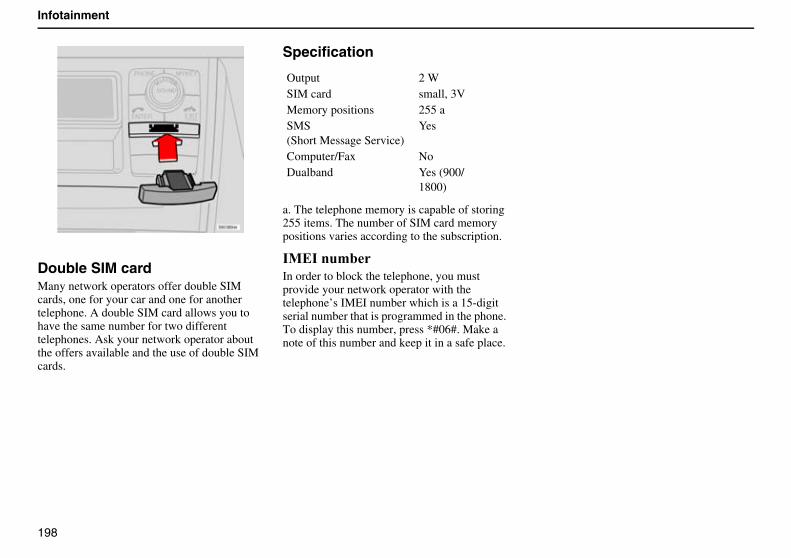
198
Infotainment
Double SIM cardMany network operators offer double SIM cards, one for your car and one for another telephone. A double SIM card allows you to have the same number for two different telephones. Ask your network operator about the offers available and the use of double SIM cards.
Specification
a. The telephone memory is capable of storing 255 items. The number of SIM card memory positions varies according to the subscription.
�0�����'��In order to block the telephone, you must provide your network operator with the telephone’s IMEI number which is a 15-digit serial number that is programmed in the phone. To display this number, press *#06#. Make a note of this number and keep it in a safe place.
Output 2 WSIM card small, 3VMemory positions 255 a SMS(Short Message Service)
Yes
Computer/Fax NoDualband Yes (900/
1800)
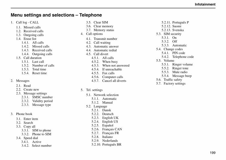
199
Infotainment
Menu settings and selections – Telephone
1. Call log - CALL
1.1. Missed calls1.2. Received calls1.3. Outgoing calls1.4. Erase list
1.4.1. All calls1.4.2. Missed calls1.4.3. Received calls1.4.4. Outgoing calls
1.5. Call duration1.5.1. Last call1.5.2. Number of calls1.5.3. Total time1.5.4. Reset time
2. Messages
2.1. Read2.2. Create new2.3. Message settings
2.3.1. SMSC number2.3.2. Validity period2.3.3. Message type
3. Phone book
3.1. Enter item3.2. Search3.3. Copy all
3.3.1. SIM to phone3.3.2. Phone to SIM
3.4. Speed dial3.4.1. Active3.4.2. Select number
3.5. Clear SIM3.6. Clear memory3.7. Memory status
4. Call options
4.1. Transmit number4.2. Call waiting4.3. Automatic answer4.4. Automatic redial4.5. Call divert
4.5.1. All calls4.5.2. When busy4.5.3. When not answered4.5.4. If unreachable4.5.5. Fax calls4.5.6. Computer calls4.5.7. Cancel all diverts
5. Tel. settings
5.1. Network selection5.1.1. Automatic5.1.2. Manual
5.2. Language5.2.1. Dansk5.2.2. Deutsch5.2.3. English UK5.2.4. English US5.2.5. Español5.2.6. Français CAN5.2.7. Français FR5.2.8. Italiano 5.2.9. Nederlands5.2.10. Português BR
5.2.11. Português P5.2.12. Suomi5.2.13. Svenska
5.3. SIM security5.3.1. On5.3.2. Off5.3.3. Automatic
5.4. Change codes5.4.1. PIN code5.4.2. Telephone code
5.5. Volume5.5.1. Ringer volume5.5.2. Ringer tone5.5.3. Mute radio5.5.4. Message beep
5.6. Traffic safety5.7. Factory settings
200
Infotainment
Menu 1. Call log($($�0� ��!��� A list of missed calls is shown here. You can choose to call, erase or store the number in the phone book.
($)$�%!����!��� A list of received calls is shown here. You can choose to call, erase or store the number in the phone book.
($*$����������!��� A list of dialled numbers is shown here. You can choose to call, erase or store the number in the phone book.
($+$��� ��� �This option can be used to erase the list of menus 1.1, 1.2 and 1.3 as follows.
1.4.1. All1.4.2. Missed1.4.3. Received1.4.4. Outgoing
($-$�"�����������Here you can see the duration of all your calls or the most recent. You can also see the number of calls and clear the call timer.
1.5.1. Last call1.5.2. Number of calls1.5.3. Total time1.5.4. Reset time.
Resetting the call timer requires the telephone code (see Menu 5.5).
Menu 2. Messages)$($�%��Here you can read received text messages. You can then choose to erase the message, forward it, change or save the entire message or parts of it.
)$)$�"�����You can write a text message using the keypad. Then choose to save or send it.
)$*$�0 ��� ����� Enter the number (SMSC number) of the message centre to which you want your messages transferred as well as how long they are to be saved at the message centre.
2.3.1. SMSC number2.3.2. Validity period2.3.3. Message type
Contact your service provider for information on these settings and for an SMSC number. Normally, these settings should not be altered.
Menu 3. Phone book*$($�������'You can store names and telephone numbers in the phone book. See the section on phone book functions for more information.
*$)$���!�
*$*$�"��������Copy SIM telephone numbers and names to the telephone memory.
3.3.1. From SIM to telephone memory3.3.2. From phone to SIM memory
*$+$���������A number stored in the telephone book can be stored as a speed dial number.
*$-$�"�����0The entire memory of the SIM card can be erased.
*$.$�"���''���The entire memory of the phone can be erased.
*$/$�0'��� ���� See how many places in the SIM card or telephone memory are occupied by names and numbers.
201
Infotainment
Menu 4. Call options+$($���� '�����'�Choose whether or not your own number should be displayed to the person you call. Contact your network operator regarding ex-directory numbers.
+$)$�"�����������Choose whether or not you want to be alerted during a phone call that there is another call coming in.
+$*$�����'���!��� �Choose to automatically accept incoming calls.
+$+$�����'���!�����Call a previously-dialled number that was engaged.
+$-$�"���������� ��!Choose when and what type of calls are to be diverted to a specified telephone number.
4.5.1. All calls (this setting only applies during the call in progress).
4.5.2. When busy4.5.3. When not answered4.5.4. If unreachable4.5.5. Fax calls4.5.6. Computer calls4.5.7. Cancel all diverts
Menu 5. Telephone settings-$($�����#� �!����Choose a network automatically or manually. The selected operator is shown in the display in the telephone’s basic mode.
5.1.1. AUTO5.1.2. Manual
-$)$�&������Here you can choose which language the telephone is to display.
5.2.1. Dansk5.2.2. Deutsch5.2.3. English UK5.2.4. English US5.2.5. Español5.2.6. Français CAN5.2.7. Français FR5.2.8. Italiano 5.2.9. Nederlands5.2.10. Portuguës BR5.2.11. Portuguës P5.2.12. Suomi5.2.13. Svenska
-$*$���0� !����Select if the PIN code should be on, off or if the telephone should automatically give the PIN code.
5.3.1. On5.3.2. Off5.3.3. Automatic
-$+$�"�����!�� Change the PIN code or telephone code.
5.4.1. PIN code5.4.2. Telephone code (use 1234 until you
change to your own code). The tele-phone code is used to reset the call timer.
������Make a note of your code as save it in a safe place.
-$-$�:���'5.5.1. Ringer volume: Here you can choose
the volume of the ringer for incom-ing calls.
5.5.2. Ringer tone: There are eight differ-ent ringer tones to choose from.
5.5.3. Mute radio: On/Off5.5.4. Speed volume: Choose whether the
volume should be adjusted according to speed.
5.5.5. Message beep
-$.$��� �!� � ��Here you can choose to disengage the speed limiter, i.e. have access to the entire menu system even while driving.
-$/$�7�!���� �����
Function to return to the system’s factory settings.

202
Infotainment
203
Specifications
Type designations 204
Measurements, weights, capacities 205
Lubricants 206
Cooling system 206
Catalytic converter 207
Petrol 208
Suspension, spring suspension 209
Electrical system 210
Engine specifications 211
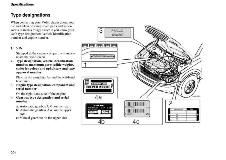
204
Specifications
Type designations
When contacting your Volvo dealer about your car and when ordering spare parts and acces-sories, it makes things easier if you know your car’s type designation, vehicle identification number and engine number.
($ :��
Stamped in the engine compartment under-neath the windscreen.
)$ ����� ��������,����!������� �!��������'�,�'�6�'�'��'� ��������� ,�!�� � ��!�������������� ���������������������'�$
Plate on the wing liner behind the left-hand headlamp.
*$ ����������� ��������,�!�'���������� ������'�
On the right-hand side of the engine+$ E���6������ ������������� ����
��'�
�� Automatic gearbox GM: on the rear���Automatic gearbox AW: on the upper
side!� Manual gearbox: on the upper side
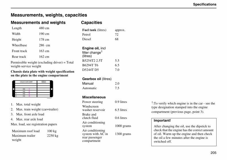
205
Specifications
Measurements, weights, capacities
Measurements and weights
Permissible weight (excluding driver) = Total weight-service weight
"�� � ���������������������� �!� �!����������������������������!�'���'��
1. Max. total weight
2. Max. train weight (car+trailer)
3. Max. front axle load
4. Max. rear axle load
Max. load, see registration papers
Capacities
1:To verify which engine is in the car - see the type designation stamped into the engine compartment (previous page, point 3).
Length 480 cm
Width 190 cm
Height 178 cm
Wheelbase 286 cm
Front track 163 cm
Rear track 162 cm
Maximum roof load 100 kgMaximum trailer weight
2250 kg
7������#�(litres) approx.Petrol 72 Diesel 68
Engine oil, incl filter change1 (litres)B5254T2 2.5T 5.5 B6294T T6 6.5 D5244T D5 7.0
Gearbox oil (litres)Manual 2.0 Automatic 7.5
MiscellaneousPower steering 0.9 litresWindscreenwasher reservoir 6.5 litresBrake andclutch fluid 0.6 litresAir conditioning system 1000 gramsAir conditioning system with AC in rear passenger compartment
1300 grams
Important!
After changing the oil, use the dipstick to check that the engine has the correct amount of oil. Warm up the engine and then check the oil a few minutes after the engine is switched off.
206
Specifications
Lubricants
EnginePetrol engines: ACEA A1
ACEA A3 grade oil can also be used. Note that the same oil can comply with both ACEA A1 and ACEA B1, regardless of whether it is a mineral, semi-synthetic or fully synthetic oil.
Diesel engines: ACEA B4
Note that the same oil can comply with ACEA A3, ACEA B3 and ACEA B4, regardless of whether the oil is mineral, semi-synthetic or fully synthetic.
Volvo fully synthetic engine oil is recom-mended for cars with turbocharged petrol engines and turbo diesel engines.
������������������ � ����������������������������� ���
Viscosity(assumes constant air temperature)
In extreme driving conditions that give abnor-mally high oil temperature or oil consumption, such as driving in the mountains with a great deal of engine braking and motorway driving at high speed, oils fulfilling the requirements of ACEA A3 (petrol engines) are recommended.
������Oils with a viscosity of 0W-30 and 0W-40 must fulfil the requirements of ACEA A3 (petrol engines).
Gearbox� �������
Manual: Volvo synthetic gearbox oil.
Geartronic: GM4T65EVVolvo synthetic gearbox oil (fulfils requirement specifications for Dexron IIIG).
Automatic: AW55-51Only Volvo gearbox oil part no.1161540-8. Do not blend with any other oil!
Power steering����� Power steering fluid of type Pentosin CHF 11S or the like.
������� approx. 0.9 litres
Brake fluid��� ������� Brake fluid DOT 4+
������� approx. 0.6 litres
Cooling system
All systems are closed overpressure systems. The thermostat starts to open at 90ºC.
Important!
If in doubt about the correct oil grade - contact a Volvo workshop
Engine �������(litres)Petrol 5-cyl 2.5T approx. 9.0 Petrol 6-cyl T6 approx. 10.5 Diesel D5 approx. 12.5
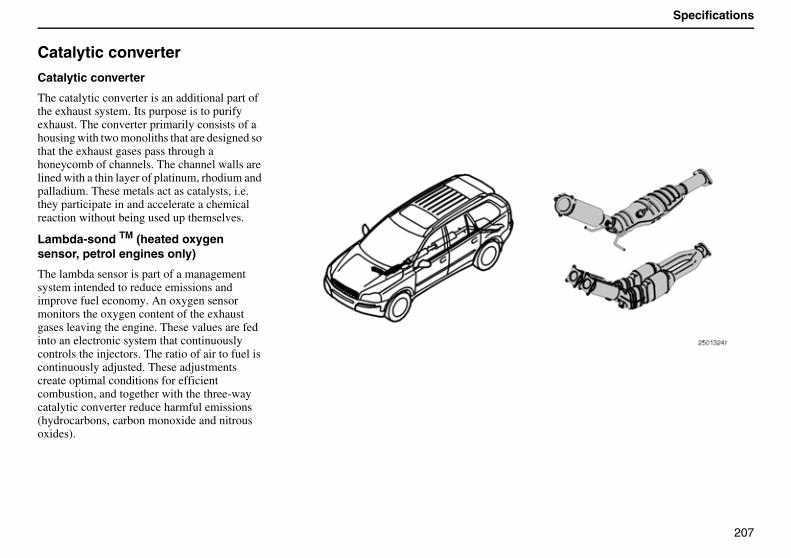
207
Specifications
Catalytic converter
Catalytic converter
The catalytic converter is an additional part of the exhaust system. Its purpose is to purify exhaust. The converter primarily consists of a housing with two monoliths that are designed so that the exhaust gases pass through a honeycomb of channels. The channel walls are lined with a thin layer of platinum, rhodium and palladium. These metals act as catalysts, i.e. they participate in and accelerate a chemical reaction without being used up themselves.
Lambda-sond TM (heated oxygen sensor, petrol engines only)
The lambda sensor is part of a management system intended to reduce emissions and improve fuel economy. An oxygen sensor monitors the oxygen content of the exhaust gases leaving the engine. These values are fed into an electronic system that continuously controls the injectors. The ratio of air to fuel is continuously adjusted. These adjustments create optimal conditions for efficient combustion, and together with the three-way catalytic converter reduce harmful emissions (hydrocarbons, carbon monoxide and nitrous oxides).
208
Specifications
Petrol
Petrol Fuel consumption and carbon dioxideThe engine can be run with octane ratings of 91, 95 and 98 RON.
• 98 RON is recommended for maximum effect and minimum fuel consumption.
• 95 RON can be used for normal driving.
• 91 RON should only be used as an exception. However, the engine will not be damaged by this fuel grade.
Standard DIN 51600
Min. 91 Octane RON Unleaded
DieselStandard EN 590
Engine Gearbox Consumption in litres/100 km
Carbon dioxide emission (CO²) g/km
B5254T2 2.5T ManuelAutomatic
11.1-11.411.8-12.0
266-273282-287
B6294T T6 Automatic 12.7-12.9 304-309
D5244T D5 ManuelAutomatic
8.2 - 8.39.0-9.1
216 - 219239-242
����� The aforementioned engines are not available in all markets.
Official fuel consumption figures are based on a standard driving cycle; EU directive 80/1268 comb.Fuel consumption figures may be altered if the car is equipped with extra options which affect car weight. The manner in which the car is driven and other non-technical factors can affect fuel consumption.
209
Specifications
Suspension, spring suspension
Front endMacPherson-type spring strut. Unitary construction of shock absorbers and spring. Rack and pinion steering. Safety type steering shaft.
Rear suspensionIndependent suspension with individually sprung wheels with shock absorbers. The suspension consists of trailing arms, upper and lower control arms, track rods and anti-roll bar.
210
Specifications
Electrical system
12-volt system with voltage regulated alternating current generator. Single pole system in which the chassis and engine block are used as conductors. The negative pole is connected to the chassis.
Bulbs Output Socket
Main beam 55 W H 7Dipped beam 55 W H 7Bi-Xenon 35 W D2R
8�����If you must replace your battery, be sure to replace it with a battery of the same cold start capacity and reserve capacity as the original (see the decal on the battery).
Fog lamps 55 W H 1Front position/parking lamp W 5 W W 2.1x9.5 dDirection indicator, front H21 W BAY9s
Engine 2.5T T6 D5 Rear direction indicator (orange) PY21 W BA 15Voltage 12 V 12 V 12 V (diesel) Side marker light W 5 W W2.1x9.5dCold start capacity (CCA) 520 A* 600 A* 800 A Brake light 21 W BA 15Reserve capacity (RC) 90 min 115 min 170 min Reversing lamp 21 W BA 15Generator max. current 140 A** 160 A 140 A** Rear fog lamp, rear position/
parking lampP21/4 W BA15
Starter motor, power 1.4 kW 1.7 kW 2.2 kW Numberplate lighting W 5 W W 2.1x9.5 dCourtesy lighting, front W 5 W SV 8.5Cargo compartment W 5 W SV 8.5Glovebox lighting W 3 W BA 9Vanity mirror 1.2 W SV 5.5
*Cars with parking heaters have an 800 A battery.** Cars with AC in the rear passenger compartment have 160 A.
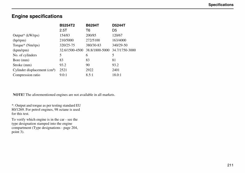
211
Specifications
Engine specifications
*: Output and torque as per testing standard EU 80/1269. For petrol engines, 98 octane is used for this test.
To verify which engine is in the car - see the type designation stamped into the engine compartment (Type designations - page 204, point 3).
B5254T2 B6294T D5244T2.5T T6 D5
Output* (kW/rps) 154/83 200/85 120/67(hp/rpm) 210/5000 272/5100 163/4000Torque* (Nm/rps) 320/25-75 380/30-83 340/29-50(kpm/rpm) 32.6/1500-4500 38.8/1800-5000 34.7/1750-3000No. of cylinders 5 6 5Bore (mm) 83 83 81Stroke (mm) 93.2 90 93.2Cylinder displacement (cm³) 2521 2922 2401Compression ratio 9.0:1 8.5:1 18.0:1
����� The aforementioned engines are not available in all markets.

212
Specifications
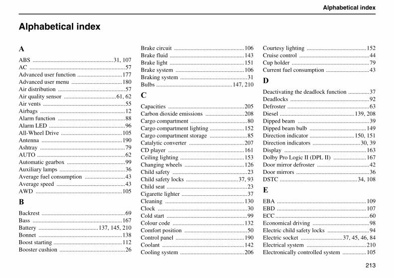
213
Alphabetical index
Alphabetical index
�ABS ......................................................31, 107AC ................................................................57Advanced user function ..............................177Advanced user menu ..................................180Air distribution .............................................57Air quality sensor ...................................61, 62Air vents .......................................................55Airbags .........................................................12Alarm function .............................................88Alarm LED ...................................................96All-Wheel Drive .........................................105Antenna ......................................................190Ashtray .........................................................79AUTO ...........................................................62Automatic gearbox .......................................99Auxiliary lamps ............................................36Average fuel consumption ...........................43Average speed ..............................................43AWD ..........................................................105
8Backrest ........................................................69Bass ............................................................167Battery ........................................137, 145, 210Bonnet ........................................................138Boost starting ..............................................112Booster cushion ............................................26
Brake circuit ...............................................106Brake fluid ..................................................143Brake light ..................................................151Brake system ..............................................106Braking system .............................................31Bulbs ...................................................147, 210
"Capacities ...................................................205Carbon dioxide emissions ..........................208Cargo compartment ......................................80Cargo compartment lighting .......................152Cargo compartment storage .........................85Catalytic converter .....................................207CD player ...................................................161Ceiling lighting ...........................................153Changing wheels ........................................126Child safety ..................................................23Child safety locks ...................................37, 93Child seat ......................................................23Cigarette lighter ............................................37Cleaning .....................................................130Clock ............................................................30Cold start ......................................................99Colour code ................................................132Comfort position ..........................................50Control panel ..............................................190Coolant .......................................................142Cooling system ...........................................206
Courtesy lighting ........................................152Cruise control ...............................................44Cup holder ....................................................79Current fuel consumption .............................43
�Deactivating the deadlock function ..............37Deadlocks .....................................................92Defroster .......................................................63Diesel ..................................................139, 208Dipped beam ................................................39Dipped beam bulb ......................................149Direction indicator ..............................150, 151Direction indicators ................................30, 39Display .......................................................163Dolby Pro Logic II (DPL II) ......................167Door mirror defroster ...................................42Door mirrors .................................................36DSTC ....................................................34, 108
�EBA ............................................................109EBD ............................................................107ECC ...............................................................60Economical driving ......................................98Electric child safety locks ............................94Electric socket ............................37, 45, 46, 84Electrical system ........................................210Electronically controlled system ................105
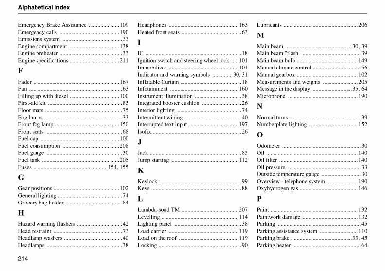
214
Alphabetical index
Emergency Brake Assistance .....................109Emergency calls .........................................190Emissions system .........................................33Engine compartment ..................................138Engine preheater ...........................................33Engine specifications ..................................211
7Fader ...........................................................167Fan ................................................................63Filling up with diesel ..................................100First-aid kit ...................................................85Floor mats .....................................................75Fog lamps .....................................................33Front fog lamp ............................................150Front seats ....................................................68Fuel cap ......................................................100Fuel consumption .......................................208Fuel gauge ....................................................30Fuel tank .....................................................205Fuses ...................................................154, 155
EGear positions .............................................102General lighting ............................................74Grocery bag holder .......................................84
DHazard warning flashers ...............................42Head restraint ...............................................73Headlamp washers ........................................40Headlamps ....................................................38
Headphones ................................................163Heated front seats .........................................63
�IC ..................................................................18Ignition switch and steering wheel lock .....101Immobilizer ................................................101Indicator and warning symbols ..............30, 31Inflatable Curtain ..........................................18Infotainment ...............................................160Instrument illumination ................................38Integrated booster cushion ...........................26Interior lighting ............................................74Intermittent wiping .......................................40Interrupted text input ..................................197Isofix..............................................................26
KJack ...............................................................85Jump starting ..............................................112
9Keylock ........................................................99Keys ..............................................................88
&Lambda-sond TM .......................................207Levelling .....................................................114Lighting panel ..............................................38Load carrier ................................................119Load on the roof .........................................119Locking .........................................................90
Lubricants ...................................................206
0Main beam ..............................................30, 39Main beam "flash" ........................................39Main beam bulb ..........................................149Manual climate control .................................56Manual gearbox ..........................................102Measurements and weights ........................205Message in the display ...........................35, 64Microphone ................................................190
�Normal turns .................................................39Numberplate lighting ..................................152
�Odometer ......................................................30Oil ...............................................................140Oil filter ......................................................140Oil pressure ..................................................33Outside temperature gauge ...........................30Overview - telephone system .....................190Oxyhydrogen gas ........................................146
�Paint ............................................................132Paintwork damage ......................................132Parking .........................................................45Parking assistance system ..........................110Parking brake ..........................................33, 45Parking heater ...............................................64
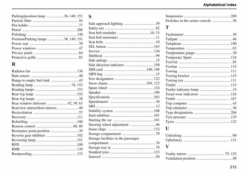
215
Alphabetical index
Parking/position lamp ..................38, 149, 151Particle filter .................................................54Pen holder .....................................................77Petrol ..........................................................208Polishing .....................................................130Position/Parking lamps .................38, 149, 151Power seat ....................................................70Power windows ............................................47Privacy panel ................................................84Protective grille ............................................83
%Radiator fan ................................................138Rain sensor ...................................................40Range to empty fuel tank .............................43Reading lamp ........................................74, 153Reading lamps ............................................153Rear fog lamp .............................................152Rear fog lamps .............................................38Rear window defroster .....................42, 59, 63Rearview mirror/door mirrors ......................49Recirculation ................................................57Recovery .....................................................111Refuelling ...................................................100Remote control .......................................88, 89Resistance point position ..............................39Reverse gear inhibitor ................................102Reversing lamp ...........................................151RFD ............................................................109RME ...........................................................139Rustproofing ...............................................133
�Safe approach lighting ..................................39Safety net ......................................................82Seat belt reminder ...................................10, 33Seat belt tensioners .......................................11Seat belts ......................................................10SEL button ..................................................163Service ........................................................136Shiftlock .......................................................99Side airbags ..................................................15Side direction indicator ..............................150SIM card .............................................190, 198SIPS bag .......................................................15Size designation ..........................................122Snow chains ........................................105, 123Spare wheel ................................................124Speaker .......................................................190Specifications .............................................203Speedometer .................................................30SRS ...............................................................12Stability system ..........................................108Start inhibitor...............................................101Starting the car ...........................................101Steering wheel adjustment ...........................46Stone chips .................................................132Storage compartment ....................................79Storage facilities in the passenger compartment .................................................76Storage tray in ..............................................79Studded tyres ..............................................123Sunroof .........................................................50
Suspension ..................................................209Switches in the centre console .....................36
�Tachometer ...................................................30Tailgate .........................................................46Telephone ....................................................190Temperature .................................................63Temperature gauge .......................................30Temporary Spare ........................................124Tool kit .........................................................85Towbar .......................................................115Towing .......................................................111Towing bracket ...........................................115Towing eye .................................................111Trailer .........................................................113Trailer indicator lamp ...................................33Tread wear indicators .................................124Treble .........................................................167Trip computer ...............................................43Trip odometer ...............................................30Type designations .......................................204Tyre pressure ..............................................125Tyres ...........................................................122
CUnlocking .....................................................90Upholstery ..................................................131
:Vanity mirror ........................................75, 152Ventilation position ......................................50
216
Alphabetical index
Viscosity .....................................................140
3Warning symbol ...........................................31Warning triangle .....................................85, 86Washer fluid reservoir ................................142Washing the car ..........................................130Waxing .......................................................131Wheels ........................................................122WHIPS .........................................................19Windscreen washer ......................................40Windscreen wiper blades ...........................144Windscreen wipers .......................................40Winter tyres ................................................123Wiper blades ...............................................144
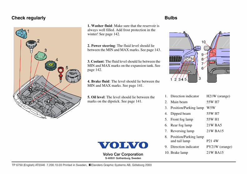
1 2 3 4 3
678
10
9
4 5
�� �������� �: Make sure that the reservoir is always well filled. Add frost protection in the winter! See page 142.
�� ���������� ��: The fluid level should lie between the MIN and MAX marks. See page 143.
�� �������: The fluid level should lie between the MIN and MAX marks on the expansion tank. See page 142.
�� ������� �: The level should lie between the MIN and MAX marks. See page 141.
�� � ������: The level should lie between the marks on the dipstick. See page 141.
1. Direction indicator H21W (orange)
2. Main beam 55W H7
3. Position/Parking lamp W5W
4. Dipped beam 55W H7
5. Front fog lamp 55W H1
6. Rear fog lamp 21W BA5
7. Reversing lamp 21W BA15
8. Position/Parking lampand tail lamp P21 4W
9. Direction indicator PY21W (orange)
10. Brake lamp 21W BA15
BulbsCheck regularly
OW
NE
R’S
MA
NU
AL
VO
LV
O X
C9
0
TP
67
50
TP 6750 (English) AT0346 7.200.10.03 Printed in Sweden, TElanders Graphic Systems AB, Göteborg 2003
XC90VOLVO
2004
52932 XC90 Eng indd 1 2003 09 12 10 01 38