Embed Size (px)
Citation preview
319
30.0 MOTORI ELETTRICIELECTRIC MOTORSELEKTROMOTORENMOTEURS ELECTRIQUES
320
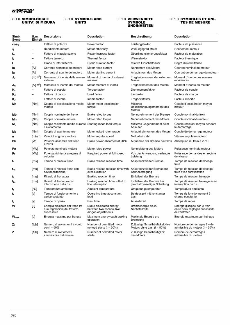
30.1.0 SYMBOLS ANDUNITS
30.1.0 VERWENDETESYMBOLEUNDINHEITEN
30.1.0 SYMBOLES ET UNI-TES DE MESURE
30.1.0 SIMBOLOGIA EUNITA’ DI MISURA
Simb.Symb.
U.m.Einheit
Descrizione Description Beschreibung Description
cos� Fattore di potenza Power factor Leistungsfaktor Facteur de puissance
� – Rendimento motore Motor efficiency Wirkungsgrad Motor Rendement moteur
fm – Fattore di maggiorazione Power increase factor Überdimensionierungsfaktor Facteur de majoration
ft – Fattore termico Thermal factor Wärmefaktor Facteur thermique
I – Grado di intermittenza Cyclic duration factor relative Einschaltdauer Degré d’intermittence
In [A] Corrente nominale del motore Motor rated current Nennstrom des Motors Courant nominal du moteur
Ia [A] Corrente di spunto del motore Motor starting current Anlaufstrom des Motors Courant de démarrage du moteur
Jc [Kgm2] Momento di inerzia delle masseesterne
Moment of inertia of externalmasses
Trägheitsmoment der externenMasse
Moment d’inertie des massesextérieures
Jm [Kgm2] Momento di inerzia del motore Motor moment of inertia Trägheitsmoment des Motors Moment d’inertie du moteur
Kc – Fattore di coppia Torque factor Drehmomentfaktor Facteur de couple
Kd – Fattore di carico Load factor Lastfaktor Facteur de charge
KJ – Fattore di inerzia Inertia factor Trägheitsfaktor Facteur d’inertie
Ma [Nm] Coppia di accelerazione mediamotore
Motor mean accelerationtorque
MittleresBeschleunigungsmoment desMotors
Couple d’accélération moyenmoteur
Mb [Nm] Coppia nominale del freno Brake rated torque Nenndrehmoment der Bremse Couple nominal du frein
Mn [Nm] Coppia nominale motore Motor rated torque Nenndrehmoment des Motors Couple nominal du moteur
ML [Nm] Coppia resistente media durantel’ avviamento
Starting mean load torque Mittleres Gegenmoment beimAnlaufen
Couple résistant moyen pendantle démarrage
Ms [Nm] Coppia di spunto motore Motor locked rotor torque Anlaufdrehmoment des Motors Couple de démarrage moteur
n [min-1] Velocità angolare motore Motor angular speed Motordrehzahl Vitesse angulaire moteur
Pb [W] Potenza assorbita dal frenoa 20°C
Brake power absorbed at 20°C Aufnahme der Bremse bei 20°C Absorption du frein à 20°C
Pn [kW] Potenza nominale motore Motor rated power Nennleistung des Motors Puissance nominale moteur
Pr [kW] Potenza richiesta a regime divelocità
Required power at full speed Von der Anwendung verlangteLeistung
Puissance demandée en régimede vitesse
t1 [ms] Tempo di rilascio freno Brake release reaction time Ansprechzeit der Bremse Temps de réaction déblocagefrein
t1s [ms] Tempo di rilascio freno consovraeccitazione
Brake release reaction time withover-excitation
Ansprechzeit der Bremse mitSchnellerregung
Temps de réaction déblocagefrein avec surexcitation
t2 [ms] Ritardo di frenatura Braking reaction time Einfallzeit der Bremse Temps de réaction freinage
t2c [ms] Ritardo di frenatura coninterruzione della c.c.
Braking reaction time with d.c.line interruption
Einfallzeit der Bremse beigleichstromseitiger Schaltung
Temps de réaction freinage avecinterruption du c.c.
ta [°C] Temperatura ambiente Ambient temperature Umgebungstemperatur Température ambiante
tf [s] Tempo di funzionamento acarico costante
Operating time at constantload
Betriebszeit mit konstanterLast
Temps de fonctionnement àcharge constante
tr [s] Tempo di riposo Rest time Aussetzzeit Temps de repos
W [J] Energia dissipata dal freno tradue regolazioni del traferrosuccessive
Brake dissipated energybetween two consecutiveair-gap adjustments
Bremsenergie bis zuNachstellreife
Energie dissipée par le freinentre deux réglages successifsde l’entrefer
Wmax [J] Energia massima per frenata Maximum energy each brakingoperation
Maximale Energie proBremsung
Energie maximum par freinage
Z0 [1/h] Numero di avviamenti a vuotocon I = 50%
Number of permitted motorno-load starts (I = 50%)
Zulässige Schalthäufigkeit desMotors ohne Last (I = 50%)
Nombre de démarrages à videadmissible du moteur (I = 50%)
Z [1/h] Numero di avviamentiammissibile del motore
Number of permitted motorstarts
Zulässige Schalthäufigkeitdes Motors
Nombre de démarragesadmissible du moteur
321
30.2.0 CARATTERISTICHEGENERALI
30.2.1 Programma diproduzione
I motori elettrici asincroni trifasedel programma di produzione del-la BONFIGLIOLI RIDUTTORIsono previsti nelle forme costrutti-ve base IMB5, IMB14 e loro deri-vate con le seguenti polarità: 4, 6.Nel presente catalogo sono evi-denziate inoltre le caratteristichetecniche dei motori in versione in-tegrata.
30.2.2 Normative
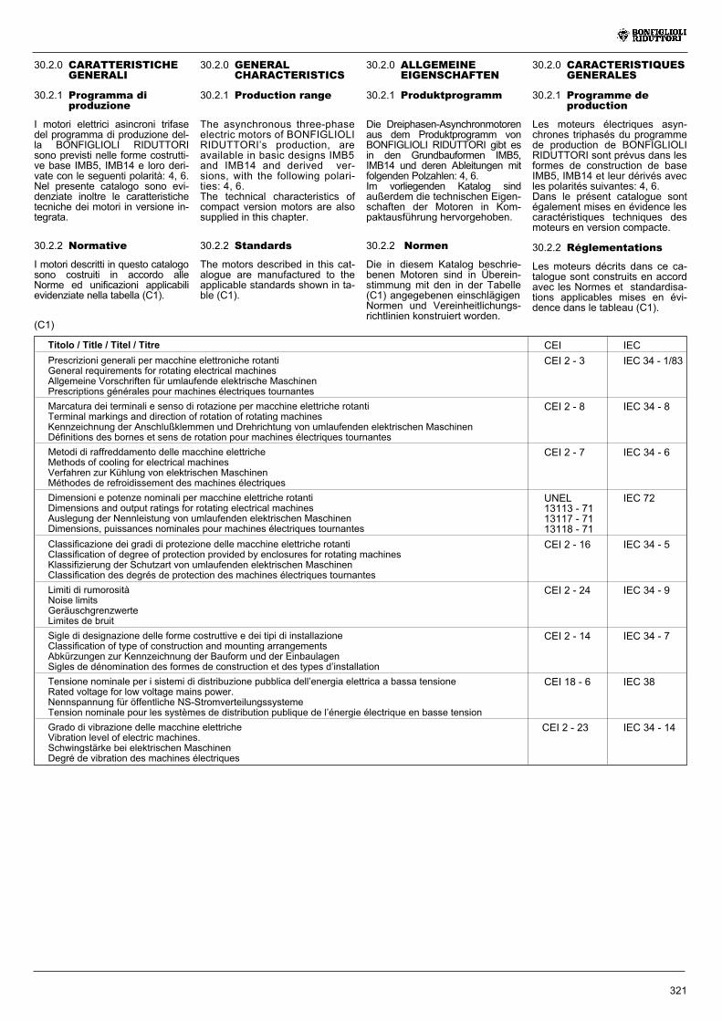
I motori descritti in questo catalogosono costruiti in accordo alleNorme ed unificazioni applicabilievidenziate nella tabella (C1).
(C1)
Titolo / Title / Titel / Titre CEI IEC
Prescrizioni generali per macchine elettroniche rotantiGeneral requirements for rotating electrical machinesAllgemeine Vorschriften für umlaufende elektrische MaschinenPrescriptions générales pour machines électriques tournantes
CEI 2 - 3 IEC 34 - 1/83
Marcatura dei terminali e senso di rotazione per macchine elettriche rotantiTerminal markings and direction of rotation of rotating machinesKennzeichnung der Anschlußklemmen und Drehrichtung von umlaufenden elektrischen MaschinenDéfinitions des bornes et sens de rotation pour machines électriques tournantes
CEI 2 - 8 IEC 34 - 8
Metodi di raffreddamento delle macchine elettricheMethods of cooling for electrical machinesVerfahren zur Kühlung von elektrischen MaschinenMéthodes de refroidissement des machines électriques
CEI 2 - 7 IEC 34 - 6
Dimensioni e potenze nominali per macchine elettriche rotantiDimensions and output ratings for rotating electrical machinesAuslegung der Nennleistung von umlaufenden elektrischen MaschinenDimensions, puissances nominales pour machines électriques tournantes
UNEL13113 - 7113117 - 7113118 - 71
IEC 72
Classificazione dei gradi di protezione delle macchine elettriche rotantiClassification of degree of protection provided by enclosures for rotating machinesKlassifizierung der Schutzart von umlaufenden elektrischen MaschinenClassification des degrés de protection des machines électriques tournantes
CEI 2 - 16 IEC 34 - 5
Limiti di rumorositàNoise limitsGeräuschgrenzwerteLimites de bruit
CEI 2 - 24 IEC 34 - 9
Sigle di designazione delle forme costruttive e dei tipi di installazioneClassification of type of construction and mounting arrangementsAbkürzungen zur Kennzeichnung der Bauform und der EinbaulagenSigles de dénomination des formes de construction et des types d’installation
CEI 2 - 14 IEC 34 - 7
Tensione nominale per i sistemi di distribuzione pubblica dell’energia elettrica a bassa tensioneRated voltage for low voltage mains power.Nennspannung für öffentliche NS-StromverteilungssystemeTension nominale pour les systèmes de distribution publique de l’énergie électrique en basse tension
CEI 18 - 6 IEC 38
Grado di vibrazione delle macchine elettricheVibration level of electric machines.Schwingstärke bei elektrischen MaschinenDegré de vibration des machines électriques
CEI 2 - 23 IEC 34 - 14
30.2.0 ALLGEMEINEEIGENSCHAFTEN
30.2.1 Produktprogramm
Die Dreiphasen-Asynchronmotorenaus dem Produktprogramm vonBONFIGLIOLI RIDUTTORI gibt esin den Grundbauformen IMB5,IMB14 und deren Ableitungen mitfolgenden Polzahlen: 4, 6.Im vorliegenden Katalog sindaußerdem die technischen Eigen-schaften der Motoren in Kom-paktausführung hervorgehoben.
30.2.0 CARACTERISTIQUESGENERALES
30.2.1 Programme deproduction
Les moteurs électriques asyn-chrones triphasés du programmede production de BONFIGLIOLIRIDUTTORI sont prévus dans lesformes de construction de baseIMB5, IMB14 et leur dérivés avecles polarités suivantes: 4, 6.Dans le présent catalogue sontégalement mises en évidence lescaractéristiques techniques desmoteurs en version compacte.
30.2.0 GENERALCHARACTERISTICS
30.2.1 Production range
The asynchronous three-phaseelectric motors of BONFIGLIOLIRIDUTTORI’s production, areavailable in basic designs IMB5and IMB14 and derived ver-sions, with the following polari-ties: 4, 6.The technical characteristics ofcompact version motors are alsosupplied in this chapter.
30.2.2 Normen
Die in diesem Katalog beschrie-benen Motoren sind in Überein-stimmung mit den in der Tabelle(C1) angegebenen einschlägigenNormen und Vereinheitlichungs-richtlinien konstruiert worden.
30.2.2 Réglementations
Les moteurs décrits dans ce ca-talogue sont construits en accordavec les Normes et standardisa-tions applicables mises en évi-dence dans le tableau (C1).
30.2.2 Standards
The motors described in this cat-alogue are manufactured to theapplicable standards shown in ta-ble (C1).
322
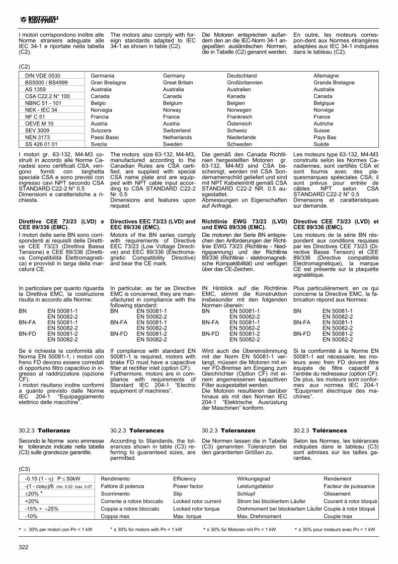
I motori corrispondono inoltre alleNorme straniere adeguate alleIEC 34-1 e riportate nella tabella(C2).
DIN VDE 0530 Germania Germany Deutschland AllemagneBS5000 / BS4999 Gran Bretagna Great Britain Großbritannien Grande BretagneAS 1359 Australia Australia Australien AustralieCSA C22.2 N° 100 Canada Canada Kanada CanadaNBNC 51 - 101 Belgio Belgium Belgien BelgiqueNEK - IEC 34 Norvegia Norway Norwegen NorvègeNF C 51 Francia France Frankreich FranceOEVE M 10 Austria Austria Österreich AutricheSEV 3009 Svizzera Switzerland Schweiz SuisseNEN 3173 Paesi Bassi Netherlands Niederlande Pays BasSS 426 01 01 Svezia Sweden Schweden Suède
(C2)
Die Motoren entsprechen außer-dem den an die IEC-Norm 34-1 an-gepaßten ausländischen Normen,die in Tabelle (C2) genannt werden.
En outre, les moteurs corres-pon-dent aux Normes étrangèresadaptées aux IEC 34-1 indiquéesdans le tableau (C2).
The motors also comply with for-eign standards adapted to IEC34-1 as shown in table (C2).
(C3)
30.2.3 Tolleranze
Secondo le Norme sono ammessele tolleranze indicate nella tabella(C3) sulle grandezze garantite.
-0.15 (1 - �) P � 50kW Rendimento Efficiency Wirkungsgrad Rendement
-(1 - cos�)/6 min. 0.02 max. 0.07 Fattore di potenza Power factor Leistungsfaktor Facteur de puissance
�20% * Scorrimento Slip Schlupf Glissement
+20% Corrente a rotore bloccato Locked rotor current Strom bei blockiertem Läufer Courant à rotor bloqué
-15% ÷ �25% Coppia a rotore bloccato Locked rotor torque Drehmoment bei blockiertem Läufer Couple à rotor bloqué
-10% Coppia max Max. torque Max. Drehmoment Couple max
* � 30% per motori con Pn < 1 kW
30.2.3 Toleranzen
Die Normen lassen die in Tabelle(C3) genannten Toleranzen beiden garantierten Größen zu.
30.2.3 Tolerances
According to Standards, the tol-erances shown in table (C3) re-ferring to guaranteed sizes, arepermitted.
30.2.3 Tolérances
Selon les Normes, les tolérancesindiquées dans le tableau (C3)sont admises sur les tailles ga-ranties.
* ± 30% pour moteurs avec Pn < 1 kW* ± 30% for motors with Pn < 1 kW * ± 30% für Motoren mit Pn < 1 kW
Die gemäß den Canada Richtli-nien hergestellten Motoren gr.63-132, M4-M3 sind CSA be-scheinigt, werden mit CSA Son-dernamenschild geliefert und sindmit NPT Kabeleintritt gemäß CSASTANDARD C22-2 NR. 0.5 au-sgestattet.Abmessungen un Eigenschaftenauf Anfrage.
Les moteurs type 63-132, M4-M3construits selon les Normes Ca-nadiennes, sont certifiés CSA etsont fournis avec des pla-quesmarques spéeciales CSA; ilsont prévus pour entrée decâbles NPT selon CSASTANDARD C22-2 N° 0.5Dimensions et carattéristiquessur demande.
The motors size 63-132, M4-M3,manufactured according to theCanadian Rules are CSA certi-fied, are supplied with specialCSA name plate and are equip-ped with NPT cable input accor-ding to CSA STANDARD C22-2Nr. 0.5Dimensions and features uponrequest.
I motori gr. 63-132, M4-M3 co-struiti in accordo alle Norme Ca-nadesi sono certificati CSA, ven-gono forniti con targhettaspeciale CSA e sono previsti coningresso cavi NPT secondo CSASTANDARD C22-2 N° 0.5Dimensioni e caratteristiche a ri-chiesta.
Direttive CEE 73/23 (LVD) eCEE 89/336 (EMC).I motori delle serie BN sono corri-spondenti ai requisiti delle Diretti-ve CEE 73/23 (Direttiva BassaTensione) e CEE 89/336 (Diretti-va Compatibilità Elettromagneti-ca) e provvisti in targa della mar-catura CE.
In particolare per quanto riguardala Direttiva EMC, la costruzionerisulta in accordo alle Norme:
BN EN 50081-1EN 50082-2
BN-FA EN 50081-1EN 50082-2
BN-FD EN 50081-2EN 50082-2
Se è richiesta la conformità allaNorma EN 50081-1, i motori confreno FD devono essere corredatidi opportuno filtro capacitivo in in-gresso al raddrizzatore (opzioneCF).I motori risultano inoltre conformia quanto previsto dalle NormeIEC 204-1 “Equipaggiamentoelettrico delle macchine”.
Directives EEC 73/23 (LVD) andEEC 89/336 (EMC).Motors of the BN series complywith requirements of DirectiveEEC 73/23 (Low Voltage Directi-ve) and EEC 89/336 (Electroma-gnetic Compatibility Directive)and bear the CE mark.
In particular, as far as DirectiveEMC is concerned, they are man-ufactured in compliance with thefollowing standard:BN EN 50081-1
EN 50082-2BN-FA EN 50081-1
EN 50082-2BN-FD EN 50081-2
EN 50082-2
If compliance with standard EN50081-1 is required, motors withbrake FD must have a capacitivefilter at rectifier inlet (option CF).Furthermore, motors are in com-pliance with requirements ofStandard IEC 204-1 “Electricequipment of machines”.
Richtlinie EWG 73/23 (LVD)und EWG 89/336 (EMC).Die motoren der Serie BN entspre-chen den Anforderungen der Richt-linie EWG 73/23 (Richtlinie - Nied-rigspannung) und der Richtlinie89/336 (Richtlinie - elektromagneti-sche Kompaktibilität) und verfügenüber das CE-Zeichen.
IN Hinblick auf die RichtlinieEMC, stimmt die Konstruktioninsbesonder mit den folgendenNormen überein:BN EN 50081-1
EN 50082-2BN-FA EN 50081-1
EN 50082-2BN-FD EN 50081-2
EN 50082-2
Wird auch die Übereinstimmungmit der Norm EN 50081-1 ver-langt, müssen die Motoren mit ei-ner FD-Bremse am Eingang zumGleichrichter (Option CF) mit ei-nem angemessenen kapazitivenFilter ausgestattet werden.Die Motoren resultieren darüberhinaus als mit den Normen IEC204-1 “Elektrische Ausrüstungder Maschinen” konform.
Directive CEE 73/23 (LVD) etCEE 89/336 (EMC).Les moteurs de la série BN rés-pondent aux conditions requisespar les Directives CEE 73/23 (Di-rective Basse Tension) et CEE89/336 (Directive compatibilitéElectromagnétique), la marqueCE est présente sur la plaquettesignalétique.
Plus particulièrement, en ce quiconcerne la Directive EMC, la fa-brication répond aux Normes:
BN EN 50081-1EN 50082-2
BN-FA EN 50081-1EN 50082-2
BN-FD EN 50081-2EN 50082-2
Si la comformité à la Norme EN50081-1 est nécessaire, les mo-teurs avec frein FD doivent êtreéquipés de filtre capacitif àl’entrée du redresseur (option CF).De plus, les moteurs sont confor-mes aux normes IEC 204-1“Equipment électrique des ma-chines”.
323
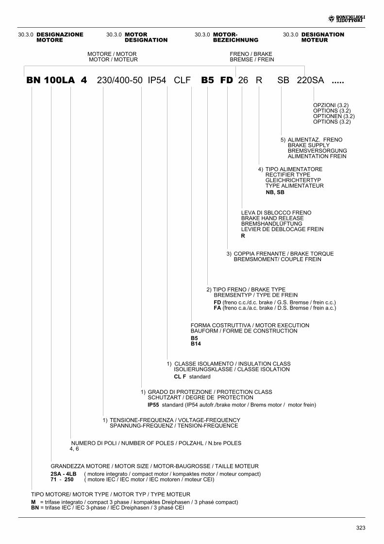
30.3.0 MOTORDESIGNATION
BN 100LA 4 230/400-50 IP54 CLF B5 FD 26 R SB 220SA .....
OPZIONI (3.2)OPTIONS (3.2)OPTIONEN (3.2)OPTIONS (3.2)
5) ALIMENTAZ. FRENOBRAKE SUPPLYBREMSVERSORGUNGALIMENTATION FREIN
4) TIPO ALIMENTATORERECTIFIER TYPEGLEICHRICHTERTYPTYPE ALIMENTATEUR
LEVA DI SBLOCCO FRENOBRAKE HAND RELEASEBREMSHANDLÜFTUNGLEVIER DE DEBLOCAGE FREIN
GRANDEZZA MOTORE / MOTOR SIZE / MOTOR-BAUGROSSE / TAILLE MOTEUR
TIPO MOTORE/ MOTOR TYPE / MOTOR TYP / TYPE MOTEUR
1) GRADO DI PROTEZIONE / PROTECTION CLASSSCHUTZART / DEGRE DE PROTECTION
3) COPPIA FRENANTE / BRAKE TORQUEBREMSMOMENT/ COUPLE FREIN
FORMA COSTRUTTIVA / MOTOR EXECUTIONBAUFORM / FORME DE CONSTRUCTION
1) CLASSE ISOLAMENTO / INSULATION CLASSISOLIERUNGSKLASSE / CLASSE ISOLATION
1) TENSIONE-FREQUENZA / VOLTAGE-FREQUENCYSPANNUNG-FREQUENZ / TENSION-FREQUENCE
NUMERO DI POLI / NUMBER OF POLES / POLZAHL / N.bre POLES4, 6
2) TIPO FRENO / BRAKE TYPEBREMSENTYP / TYPE DE FREIN
MOTORE / MOTORMOTOR / MOTEUR
FRENO / BRAKEBREMSE / FREIN
M = trifase integrato / compact 3 phase / kompaktes Dreiphasen / 3 phasé compact)BN = trifase IEC / IEC 3-phase / IEC Dreiphasen / 3 phasé CEI
CL F standard
IP55 standard (IP54 autofr./brake motor / Brems motor / motor frein)
B5B14
FD (freno c.c./d.c. brake / G.S. Bremse / frein c.c.)FA (freno c.a./a.c. brake / D.S. Bremse / frein a.c.)
R
NB, SB
2SA - 4LB ( motore integrato / compact motor / kompaktes motor / moteur compact)71 - 250 ( motore IEC / IEC motor / IEC motoren / moteur CEI)
30.3.0 MOTOR-BEZEICHNUNG
30.3.0 DESIGNATIONMOTEUR
30.3.0 DESIGNAZIONEMOTORE
324
30.3.1 Note motori
1)- TENSIONE - FREQUENZADa indicare sempre. Tensioni standardcome descritto al par. 30.5.1.
- GRADO DI PROTEZIONEProtezione IP56 (IP55 per autofrenan-ti) a richiesta.
- CLASSE DI ISOLAMENTOClassi di isolamento H a richiesta.
2) TIPO DI FRENODisponibile, a richiesta, freno FA (fre-no c.a.).Se non specificato il freno è omesso.
3) COPPIA FRENANTEValori standard come riportato nelletabelle dati motore.Altre coppie a richiesta (vedi tab. C23- tipo FD, per tipo FA veditab. C27).
4) TIPO DI ALIMENTATOREDa indicare solo per freni FD.A richiesta, per i freni FD02, FD03,FD53, FD04, FD14, FD05, FD15, puòessere fornito il raddrizzatore SB.
5) ALIMENTAZIONE FRENO
Freni tipo FDTensione alimentazione come descrit-to al parag. 6.2.Per alimentazione freno separata indi-care:a) il valore di tensione richiestoseguito da SA ( p.e. 290SA);b) nel caso di alimentazione direttadel freno in c.c. indicare il valore ditensione seguito da SD (p.e. 24SD);in questo caso il raddrizzatore èescluso dalla fornitura.Freni tipo FATensione alimentazione come descrit-to al par. 30.6.3.Per alimentazione freno separata indi-care il valore di tensione seguito daSA (p.e. 290SA).
Se non specificati espressamente, idati previsti nei campi sopra indi-cati saranno assunti corrispondentialla versione standard a catalogo.
30.3.2 Opzioni motori
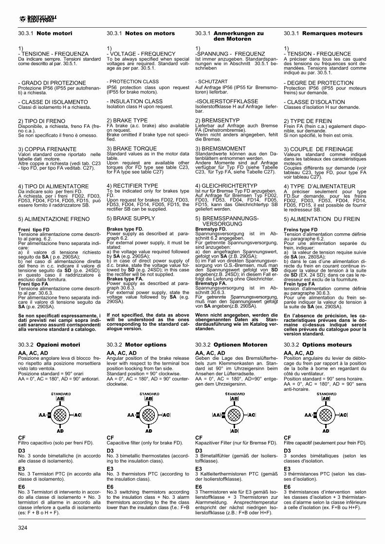
AA, AC, ADPosizione angolare leva di blocco fre-no rispetto alla posizione morsettieravisto lato ventola.Posizione standard = 90° orariAA = 0°, AC = 180°, AD = 90° antiorari.
CFFiltro capacitivo (solo per freni FD).
D3No. 3 sonde bimetalliche (in accordoalle classe di isolamento).
E3No. 3 Termistori PTC (in accordo allaclasse di isolamento).
E6No. 3 Termistori di intervento in accor-do alla classe di isolamento + No. 3termistori di allarme in accordo allaclasse inferiore a quella di isolamento(es: F + B o H + F).
30.3.1 Anmerkungen zuden Motoren
1)-SPANNUNG - FREQUENZIst immer anzugeben. Standardspan-nungen wie in Abschnitt 30.5.1 be-schrieben
- SCHUTZARTAuf Anfrage IP56 (IP55 für Bremsmo-toren) lieferbar.
-ISOLIERSTOFFKLASSEIsolierstoffklasse H auf Anfrage liefer-bar.
2) BREMSENTYPLieferbar auf Anfrage auch BremseFA (Drehstrombremse).Wenn nicht anders angegeben, fehltdie Bremse.
3) BREMSMOMENTStandardwerte können aus den Da-tenblättern entnommen werden.Andere Momente sind auf Anfrageverfügbar für Typ FD (siehe TabelleC23, für Typ FA, siehe Tabelle C27).
4) GLEICHRICHTERTYPIst nur für Bremse Typ FD anzugeben.Auf Anfrage für Bremsen Typ FD02,FD03, FD53, FD04, FD14, FD05,FD15, kann das Gleichrichtertyp SBgeliefert werden.
5) BREMSSPANNUNGS-VERSORGUNG
Bremstyp FD.Spannungsversorgung ist im Ab-schnitt 6.2 angegeben.Für getrennte Spannungsversorgung,sind anzugeben:a) den angefragten Spannungswert,gefolgt von SA (z.B. 290SA);b) im Fall von direkten Spannungsver-sorgung von G.S.-Bremsen, muß manden Spannungswert gefolgt von SDangeben(z.B. 24SD); in diesem Fall er-folgt die Lieferung ohne Gleichrichter.Bremstyp FA.Spannungsversorgung ist im Ab-schnitt 30.6.3.Für getrennte Spannungsversorgung,muß man den Spannungswert gefolgtvon SA angeben(z.B. 290SA).
Wenn nicht angegeben, werden dieobengenannten Daten als Stan-dardausführung wie im Katalog ver-standen.
30.3.1 Remarques moteurs
1)- TENSION - FREQUENCEA préciser dans tous les cas quanddes tensions ou fréquences sont de-mandées. Tensions standard commeindiqué au par. 30.5.1.
- DEGRE DE PROTECTIONProtection IP56 (IP55 pour moteursfreins) sur demande.
- CLASSE D’ISOLATIONClasses d’isolation H sur demande.
2) TYPE DE FREINFrein FA (frein c.a.) egalement dispo-nible, sur demande.Si non spécifié, le frein est omis.
3) COUPLE DE FREINAGEValeurs standard comme indiquédans les tableaux des caractéristiquesmoteurs.Couples différents sur demande (voirtableau C23, type FD, pour type FAvoir tableau C27).
4) TYPE D’ALIMENTATEURA préciser seulement pour typeFD.Sur demande, pour les freinsFD02, FD03, FD53, FD04, FD14,FD05, FD15, il est possible de fournirle redresseur SB.
5) ALIMENTATION DU FREIN
Freins type FDTension d’alimentation comme définieau paragraphe 6.2.Pour une alimentation separée dufrein, indiquer:a) la valeur de tension requise suiviede SA (ex. 280SA);b) dans le cas d’une alimentation di-recte du frein en courant continue in-diquer la valeur de tension à la suitede SD (EX. 24 SD); dans ce cas le re-dresseur est exclu de la fourniture.Frein type FAtension d'alimentation comme définieau paragraphe 30.6.3.Pour une alimentation du frein se-parée indiquer la valeur de tension àla suite de SA (ex. 290SA).
En l’absence de précision, les ca-racteristiques prévues dans le do-maine ci-dessus indiqué serontcelles prévues du catalogue pour laversion standard.
30.3.1 Notes on motors
1)- VOLTAGE - FREQUENCYTo be always specified when specialvoltages are required. Standard volt-age as per par. 30.5.1.
- PROTECTION CLASSIP56 protection class upon request(IP55 for brake motors).
- INSULATION CLASSIsolation class H upon request.
2) BRAKE TYPEFA brake (a.c. brake) also availableon request.Brake omitted if brake type not speci-fied.
3) BRAKE TORQUEStandard values as in the motor datatable.Upon requiest are available othertorques (for FD type see table C23,for FA type see table C27)
4) RECTIFIER TYPETo be indicated only for brakes typeFD.Upon request for brakes FD02, FD03,FD53, FD04, FD14, FD05, FD15, therectifier SB can be supplied.
5) BRAKE SUPPLY
Brakes type FD.Power supply as described at para-graph 6.2.For external power supply, it must bestated:a) the voltage value required followedby SA (e.g. 290SA);b) in case of direct power supply ofd.c. brake, state the voltage value fol-lowed by SD (e.g. 24SD); in this casethe rectifier will be not supplied.Brakes type FA.Power supply as described at para-graph 30.6.3.For external power supply, state thevoltage value followed by SA (e.g.290SA).
If not specified, the data as abovewill be understood as the onescorresponding to the standard cat-alogue version.
30.3.2 Motor options
AA, AC, ADAngular position of the brake releaselever with respect to the terminal boxposition loocking from fan side.Standard position = 90° clockwise.AA = 0°, AC = 180°, AD = 90° counter-clockwise.
CFCapacitive filter (only for brake FD).
D3No. 3 bimetallic thermostates (accord-ing to the insulation class).
E3No. 3 thermistors PTC (according tothe insulation class).
E6No.3 switching thermistors accordingto the insulation class + No. 3 alarmthermistors according to the the classlower than the insulation class (f.e.: F+B
30.3.2 Optionen Motoren
AA, AC, ADGeben die Lage des Bremslüfterhe-bels zum Klemmenkasten an. Stan-dard ist 90° im Uhrzeigersinn beimAnsehen der Lüfterradseite.AA = 0°, AC = 180°, AD=90° entge-gen dem Uhrzeigersinn.
CFKapazitiver Filter (nur für Bremse FD).
D33 Bimetallfühler (gemäß der Isoliers-toffklasse).
E33 Kaltleiterthermistoren PTC (gemäßder Isolierstoffklasse).
E63 Thermistoren wie für E3 gemäß Iso-lierstoffklasse + 3 Thermistoren zurAlarmmeldung. Ansprechtemperaturentspricht der nächst niedrigen Iso-lierstoffklasse (z.B.: F+B oder H+F).
30.3.2 Options moteurs
AA, AC, ADPosition angulaire du levier de déblo-cage du frein par rapport à la positionde la boîte à borne en regardant ducôté du ventilateur.Position standard = 90° sens horaire.AA = 0°, AC = 180°, AD = 90° sensanti-horaire.
CFFiltre capacitif (seulement pour frein FD).
D33 sondes bimétalliques (selon lesclasses d'isolation.
E33 thérmistances PTC (selon les clas-ses d’isolation).
E63 thérmistances d’intervention selonles classes d’isolation + 3 thérmistan-ces d’alarme selon la classe inférieureà celle d’isolation (ex. F+B ou H+F).
325
F1Volano per avviamento progressivo(escluso BN160 - BN280.
H1Riscaldatori anticondensa.Alimentazione standard 230V ± 10%.M3Morsettiera a 9 morsetti(Escluso gr. 71).PNPotenza a 60 Hz corrispondente allapotenza normallizzata a 50 Hz.PSDoppia estremità d’albero (escludeopzione RC e U1).PTMotore standard 220/380 - 50 Hzalimentato a 220/380 - 60 Hz (condeclassamento di coppia ).RCTettuccio parapioggia(esclude opzione PS).RVBilanciamento rotore in grado divibrazione R.TPTropicalizzazione.U1Servoventilazione(esclude opzione PS).
F1Flywheel for soft start (excludingBN160 - BN 280).
H1Anti-condensate heaters.Standard voltage 230V ± 10%.M3Terminal box: 9 terminals.(Sizes 71 excluded).PN60 Hz power corresponding to thenormalised 50 Hz power.PSDouble shaft extension (excluding RCand U1 options).PTStandard motor 220/380V - 50 Hzsupplied at 220/380V - 60 Hz (withtorque derating).RCRain canopy(excluding option PS).RVRotor balancing in vibration class R.
TPTropicalization.U1Servoventilation(excluding option PS).
F1Schwungrad zum sanften Anfahren(schließt BN160 - BN280).
H1Wicklungsheizung.Standardspannung 230 V ± 10%.M3Klemmkasten mit 9 Klemmen. (MitAusnahme von Baugröße 71).PNDie 60 Hz- Leistung wird an 50 HzNormleistung angegliechen.PSZweites Wellenende (schließt dieOptionen RC und U1 aus).PTDer standardmäßig an 220/380V - 50Hz zu betreibenden Motor wird mit derLeistung bei 220/380V- 60 Hz getrieben.RCSchutzdach(schließt Option PS aus).RVLäufer in Vibrationsgrad R aus-gewuchtet.TPTropenfestigkeit.U1Fremdbelüftung(schließt Option PS aus).
F1Volant pour démarrage progressif(exclue BN160 - BN280)
H1Réchauffeurs anticondensation.Alimentation standard 230 V ± 10%.M3Boîte à bornes (9 bornes).(Exclu taille 71).PNPuissance à 60 Hz correspondante àla puissance normalisée à 50 Hz.PSDouble extrémité d’arbre (à l’exclusionde l’option RC et U1).PTMoteur standard 220/380- 50 Hzalimenté à 220/380 - 60 Hz (avecdéclassement de couple ).RCCapot de protection antipluie(exclu option PS).RVEquilibrage rotor avec degré devibration R.TPTropicalisation.U1Servo-ventilateur (option PS exclue).
30.4.0 CARATTERISTICHEMECCANICHE
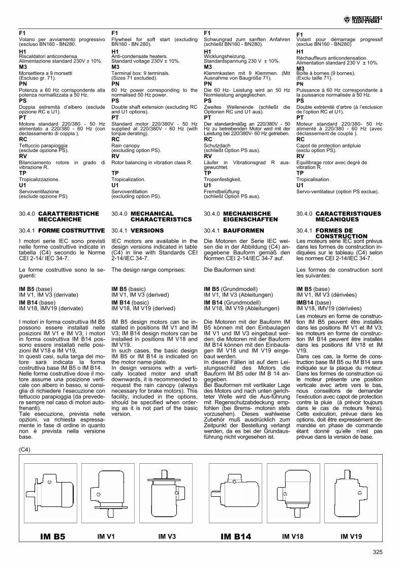
30.4.1 FORME COSTRUTTIVE
I motori serie IEC sono previstinelle forme costruttive indicate intabella (C4) secondo le NormeCEI 2-14/ IEC 34-7.
Le forme costruttive sono le se-guenti:
IM B5 (base)IM V1, IM V3 (derivate)
IM B14 (base)IM V18, IMV19 (derivate)
I motori in forma costruttiva IM B5possono essere installati nelleposizioni IM V1 e IM V3; i motoriin forma costruttiva IM B14 pos-sono essere installati nelle posi-zioni IM V18 e IM V19,In questi casi, sulla targa del mo-tore sarà indicata la formacostruttiva base IM B5 o IM B14.Nelle forme costruttive dove il mo-tore assume una posizione verti-cale con albero in basso, si consi-glia di richiedere l’esecuzione contettuccio parapioggia (da prevede-re sempre nel caso di motori auto-frenanti).Tale esecuzione, prevista nelleopzioni, va richiesta espressa-mente in fase di ordine in quantonon è prevista nella versionebase.
IM V3IM B5 IM B14 IM V18 IM V19IM V1
(C4)
30.4.0 MECHANISCHEEIGENSCHAFTEN
30.4.1 BAUFORMEN
Die Motoren der Serie IEC wei-sen die in der Abbildung (C4) an-gegebene Bauform gemäß denNormen CEI 2-14/IEC 34-7 auf.
Die Bauformen sind:
IM B5 (Grundmodell)IM V1, IM V3 (Ableitungen)
IM B14 (Grundmodell)IM V18, IM V19 (Ableitungen)
Die Motoren mit der Bauform IMB5 können mit den EinbaulagenIM V1 und IM V3 eingebaut wer-den; die Motoren mit der BauformIM B14 können mit den Einbaula-gen IM V18 und IM V19 einge-baut werden.In diesen Fällen ist auf dem Lei-stungsschild des Motors dieBauform IM B5 oder IM B 14 an-gegeben.Bei Bauformen mit vertikaler Lagedes Motors und nach unten gerich-teter Welle wird die Aus-führungmit Regenschutzabdeckung emp-fohlen (bei Brems- motoren stetsvorzusehen). Dieses wahlweiseZubehör muß ausdrücklich zumZeitpunkt der Bestellung verlangtwerden, da es bei der Grundaus-führung nicht vorgesehen ist.
30.4.0 CARACTERISTIQUESMECANIQUES
30.4.1 FORMES DECONSTRUCTION
Les moteurs série IEC sont prévusdans les formes de construction in-diquées sur le tableau (C4) selonles normes CEI 2-14/IEC 34-7.
Les formes de construction sontles suivantes:
IM B5 (base)IM V1, IM V3 (dérivées)
IMB14 (base)IM V18, IMV19 (dérivées)
Les moteurs en forme de construc-tion IM B5 peuvent être installésdans les positions IM V1 et IM V3;les moteurs en forme de construc-tion IM B14 peuvent être installésdans les positions IM V18 et IMV19.Dans ces cas, la forme de cons-truction base IM B5 ou IM B14 seraindiquée sur la plaque du moteur.Dans les formes de construction oùle moteur présente une positionverticale avec arbre vers le bas,nous conseillons de demanderl’exécution avec capot de protectioncontre la pluie (à prévoir toujoursdans le cas de moteurs freins).Cette exécution, prévue dans lesoptions, doit être expressément de-mandée en phase de commandeétant donné qu’elle n’est pasprévue dans la version de base.
30.4.0 MECHANICALCHARACTERISTICS
30.4.1 VERSIONS
IEC motors are available in thedesign versions indicated in table(C4) in line with Standards CEI2-14/IEC 34-7.
The design range comprises:
IM B5 (basic)IM V1, IM V3 (derived)
IM B14 (basic)IM V18, IM V19 (derived)
IM B5 design motors can be in-stalled in positions IM V1 and IMV3; IM B14 design motors can beinstalled in positions IM V18 andIM V19.In such cases, the basic designIM B5 or IM B14 is indicated onthe motor name plate.In design versions with a verti-cally located motor and shaftdownwards, it is recommended torequest the rain canopy (alwaysnecessary for brake motors). Thisfacility, included in the options,should be specified when order-ing as it is not part of the basicversion.
326
30.4.2 Grado di protezione
I motori sono previsti nella solu-zione standard con un grado diprotezione IP55 (IP54 per auto-frenante) in accordo alle NormeCEI 2-16 / IEC 34-5.Su richiesta possono essere forniticon grado di protezione aumenta-to IP56 (IP55 per autofrenante).Per installazione all’aperto i mo-tori debbono essere protettidall’irraggiamento diretto e, nelcaso di montaggio in posizioneverticale con l’albero in basso, ènecessario prevedere il tettucciodi protezione.
30.4.3 Ventilazione
I motori sono raffreddati medianteventilazione esterna (IC 411 se-condo CEI 2-7 / IEC 34-6) e sonoprovvisti di ventola radiale in pla-stica che funziona in entrambi isensi di rotazione.L’installazione deve assicurare unadistanza minima dalla calotta copri-ventola alla parete in modo da nonavere impedimenti all’ingresso ariae permettere la possibilità di ese-guire l’opportuna manutenzione delmotore e, se previsto, del freno.Su richiesta è possibile prevedereuna ventilazione forzata indipen-dente (IC 416). Questa soluzioneconsente di aumentare il fattore diutilizzo del motore nel caso di ali-mentazione da inverter e funziona-mento a giri ridotti (vedi par. 30.7.3per maggiori dettagli).
30.4.4 Senso di rotazione
E’ possibile il funzionamento dientrambi i sensi di rotazione.Con collegamento dei morsettiU1,V1,W1 alle fasi di lineaL1,L2,L3 si ha rotazione oraria vi-sta dal lato accoppiamento, men-tre la marcia antioraria si ottienescambiando fra loro due fasi.
30.4.5 Rumorosità
I valori di rumorosità, rilevati se-condo il metodo previsto dalleNorme ISO 1680, sono contenutientro i livelli massimi previsti dal-le Norme CEI 2-24 / IEC 34-9.
30.4.6 Vibrazioni edequilibratura
Tutti i motori sono equilibrati conmezza linguetta e rientrano nei li-miti di intensità di vibrazione pre-visti dalle Norme CEI 2-23 / IEC34-14.Per particolari esigenze di silen-ziosità potrà essere previsto, a ri-chiesta, un'esecuzione antivi-brante in grado ridotto (R).La tabella (C5) riporta i valoridella velocità efficace di vibrazio-ne per equilibratura normale (N)e ridotta (R).
30.4.2 Schutzart
Die Motoren verfügen in derStandardausführung gemäß denNormen CEI 2-16 und IEC 34-5über die Schutzart IP55 (IP54 beiBremsmotoren).Auf Wunsch können sie auch mitSchutzart IP56 (IP55 fürBrems-motoren) geliefert werden.Bei Installation im Freien müssendie Motoren vor direkter Son-neneinstrahlung geschützt und,wenn bei vertikaler Einbaulageund Welle nach unten, mit einerSchutzabdeckung versehen wer-den.
30.4.3 Lüftung
Die Motoren sind eigenbelüftet(IC 411 gemäß CEI 2-7 / IEC34-6) und verfügen über ein Ra-diallüfterrad aus Kunststoff, dasin beiden Drehrichtungen arbei-ten kann.Bei der Installation muß sicherge-stellt werden, daß die Lüfter-rad-abdeckung soweit von derWand entfernt ist, daß der Luft-eintritt nicht behindert wird, unddaß der Motor und (falls vorhan-den) die Bremse problemlos ge-wartet werden können.Auf Wunsch können die Motorenmit Fremdbelüftung geliefert wer-den (IC 416). Diese Lösung er-möglicht das Motorbetriebsfaktorzu erhöhen, wenn vom Fre-quenzumrichter gesteuert und zuniedrigen Geschwindigkeit betrie-ben (siehe Abschnitt 30.7.3 fürweitere Informationen).
30.4.4 Drehrichtung
Der Betrieb in beiden Drehrichtun-gen ist möglich.Schließt man die Klemmen U1,V1, W1 an die Phasen L1, L2, L3an, dreht sich der Motor im Uhr-zeigersinn (von der Verbindungs-seite her betrachtet); die Drehungim Gegenuhrzeigersinn erhältman, indem man zwei Phasenvertauscht.
30.4.5 Geräuschpegel
Die mit der von der ISO-Norm1680 vorgesehenen Methodengemessenen Lärmstärkewerteliegen innerhalb der gemäß denNormen CEI 2-24 und IEC 34-9zulässigen Höchstgrenzen.
30.4.6 Schwingungen undAusgleich
Alle Rotoren werden durch einenhalben Federkeil ausgeglichenund fallen somit unter die, vonden Normen CEI 2-23 / IEC34-14 vorgesehenen Scwin-gungsgradgrenzen.Bei besonderen Anforderungenan die Laufruhe kann auf Anfra-ge eine schwingungsdämpfendeAusführung in der reduziertenKlasse (R) geliefert werden.Die tabelle (C5) führt die Effek-tivwerte der Schwingungsge-schwindigkeit für einen normalen(N) und reduzierten (R) Aus-gleich auf.
30.4.2 Protection class
Motors are supplied standardwith IP55 protection class (IP54for brake motors) to CEI stan-dards 2-16 / IEC 34-5.On request, motors can be sup-plied with a higher protection classIP56 (IP55 for brake motors).For outdoor installation, motorsmust be protected from directsunlight and if mounted verticallywith shaft downwards, the raincanopy must be provided.
30.4.3 Ventilation
The motors are cooled by exter-nal ventilation (IC 411 to CEI 2-7/ IEC 34-6) and are equipped witha plastic fan working in both di-rections.The motors must be installed al-lowing sufficient space betweenfan cowl and nearest wall to en-sure free air intake and allow ac-cess for maintenance on motorand brake, if supplied.Independent, forced air ventila-tion (IC 416) can be supplied onrequest.This solution enables to increasethe motor duty factor when drivenby an inverter and operating atreduced speed (for further de-tails, refer to paragraph 30.7.3)
30.4.4 Direction of rotation
Rotation is possible in both direc-tions. If terminals U1, V1, and W1are connected to line phases L1,L2and L3, clockwise rotation (lookingfrom drive end) is obtained. Forcounterclockwise rotation, switchtwo phases.
30.4.5 Noise
Noise levels, measured using themethod prescribed by ISO 1680Standards, are within the maxi-mum levels specified by Stan-dards CEI 2-24 / IEC 34-9.
30.4.6 Vibrations andbalancing
All rotors are balanced with halfkey and fall within the vibrationclass N, as specified by StandardCEI 2-23 / IEC 34-14.If a particular low noise level isrequired, upon requeset, a re-duced degree antivibration ver-sion (R) is available.Table (C5) shows the effective vi-bration speed values for standard(N) and reduced (R) balancing.
30.4.2 Degré de protection
Les moteurs sont prévus dans laversion standard avec un degréde protection IP55 (IP54 pourmoteur frein) conformément auxnormes CEI 2-16 / IEC 34-5.Sur demande, ils peuvent êtrefournis avec un degré de protec-tion supérieur IP56 (IP55 pourmoteurs freins). Pour l’installationà ciel ouvert, les moteurs doiventêtre protégés du rayonnement di-rect et dans le cas de montageen position verticale, avec l’arbreen bas, il est nécessaire de pré-voir un capot de protection.
30.4.3 Ventilation
Les moteurs sont refroidis à l’aided’une ventilation extérieure (IC411 selon CEI 2-7, IEC 34-6) etsont dotés d’un ventilateur à ailet-tes en plastique qui fonctionnedans les deux sens de rotation.L’installation doit assurer une dis-tance minimum entre le capot deprotection du ventilateur et la pa-roi afin de permettre une bonnecirculation de l’air et rendre plusaisé l’entretien du moteur et siprévu, du frein.Sur demande, il est possible deprévoir une ventilation forcée in-dépendante (IC 416).Cette solution permet d’augmenterle facteur d’utilisation du moteur encas d’alimentation, via un variateurde fréquence, et pour un fonction-nement à faible vitesse (voir para-graphe 30.7.3 pour plus de dé-tails).
30.4.4 Sens de rotation
Un fonctionnement dans les deuxsens de rotation est possible.Avec raccordement des bornesU1, V1,W1 aux phases de ligneL1, L2,L3, on a la rotation dans lesens des aiguilles d’une montrevue du côté liaison alors que lesens inverse s’obtient en interver-tissant les deux phases entre el-les.
30.4.5 Niveau de bruit
Les valeurs relevées selon la mé-thode prévue par les normes ISO1680 sont situées sous les ni-veaux maximums prévus par lesnormes CEI 2-24 / IEC 34-9.
30.4.6 Vibrations etéquilibrage
Tous les rotors sont équilibrèsavec une demi languette et ren-trent dans les limites d'intensitéde vibration prévues par les Nor-mes CEI 2-23 / IEC 34/14.En cas d'exigences particulièreconcernat le niveau de bruit, surdemande, il est possible de réali-ser une exécution anti-vibrante,de degré réduit (R).
Le tableau (C5) indique lesvaleurs de la vitesse efficace devibration pour un équilibrage nor-mal (N) et rèpduit (R).
327
Tipo / Motor type / Motortyp / Moteur type Avviamento / StartingStart / Démarrage
Numero morsetti / Number of terminalsKlemmenanzahl / Nombre bornes
Filettatura perni di attacco / Terminal threadsGewinde der Verbindungszapfen / Filetage
axe de fixation
BN 71 —
direttodirectdirektdirect
6
M4
BN 80 - 90 M2. M4
BN 100 - 112 M3. M5
BN 132 M4. M5
BN 160 — M6
(C7)
30.4.8 Morsettiera motore
La scatola coprimorsettiera è pre-vista di serie con un bocchettonepressacavo. La morsettiera princi-pale è a sei morsetti per collega-mento con capicorda. All’internodella scatola è previsto un morset-to per il conduttore di protezione.Le dimensioni dei perni di attaccosono riportate nella tabella (C7).Nel caso di motori autofrenanti, ilraddrizzatore per l’alimentazionedel freno è fissato all’interno dellascatola e provvisto di adeguatimorsetti di collegamento.Eseguire i collegamenti secondogli schemi riportati all’interno del-la scatola coprimorsetti o nei ma-nuali d’uso.
Componenti / Components / Komponenten / Composants Dimensioni / DimensionsAbmessungen / Dimensions
Tolleranza / ToleranceToleranz / Tolérance
Estremità albero / Shaft extension / Wellenende / Extrémité arbre D - DA
ø 14 � 28 j6
ø 38 � 48 k6
ø 55 � 100 m6
Linguetta / Key / Federkeil / Clavette F - FA h9
Flangia / Flange / Flansch / Bride N< ø 250 j6
� ø 250 h6
I valori si riferiscono a misure conmotore liberamente sospeso e fun-zionamento a vuoto.
30.4.7 Tolleranzedimensionali
L’estremità d’albero, la linguetta ela flangia hanno dimensioni e tol-leranze secondo CEI-UNEL13502, CEI-UNEL 13501, IEC 72.Le estremità d’albero sono provvi-ste di foro filettato in testa secon-do UNI 3221, DIN 332.I motori vengono forniti con lin-guetta inserita.La tabella (C6) riporta le tolleran-ze relative ai componenti dei mo-tori elettrici BONFIGLIOLI RIDUT-TORI.
30.4.7 Toleranzen
Die Wellenende-,Feder-und Flan-schabmessungen und -toleranzensind gemäß CEI-UNEL 13502,CEI-UNEL 13501, IEC 72.Die Wellenenden sind mit Gewin-debohrung auf den Kopf gemäßUNI 3221, DIN 332 geliefert.Die Motoren werden mit Federkeilgeliefert.Die Tabelle (C6) zeigt die Toleran-zen der Komponenten der Elek-tromotoren von BONFIGLIOLI RI-DUTTORI.
30.4.7 Tolérances
Le bout d’arbre, la clavette et labride ont les dimensions et les to-lérances selon CEI-UNEL 13502,CEI-UNEL 13501, IEC 72.Les bouts d’arbre sont prévusavec trous taraudés selon UNI3221, DIN 332.Les moteurs sont fournis avecclavette montée.Le tableau (C6) présente les tolé-rances relatives aux composantsdes moteurs électriques BONFI-GLIOLI RIDUTTORI.
30.4.7 Tolerances
Dimensions and tolerances ofshaft ends, keys and flanges areaccording to CEI-UNEL 13502,CEI-UNEL 13501, IEC 72.The shaft ends are supplied withtapped hole on the head accord-ing to UNI 3221, DIN 332.The motors are supplied with key.Table (C6) shows tolerances forcomponents of BONFIGLIOLI RI-DUTTORI electric motors.
30.4.8 Motorklemmenkasten
Der Klemmkasten verfügt serien-mäßig über eine Kabeldurch-füh-rung. Die Hauptklemmleiste hat 6Klemmen für den Anschluß mitKabelschuhen. Im Innern desKlemmenkasten befindet sich eineKlemme für den Schutzleiter.Die Abmessungen der Auschüssesind in Tabelle (C7) angegeben.Bei den Bremsmotoren befindetsich auch der mit den erforderli-chen Anschlußklemmen ausge-stattete Gleichrichter für dieStromversorgung der Bremse imKlemmenkasten.Die Anschlüße müssen gemäßden Diagrammen im Klemmkas-ten oder in den Betriebsanwie-sungen durchgeführt werden.
30.4.8 Bornier moteur
Le couvercle du bornier est prévude série avec un presseétoupe defixation du câble. Le bornier princi-pal prevoit six bornes pour raccor-dement avec cosses. Dans le boî-tier se trouve une borne pour leconducteur de protection. Les di-mensions des axes de fixationsont reportées dans le tableau(C7).Dans le cas de moteurs freins, leredresseur pour l’alimentation dufrein est fixé à l’intérieur du boî-tier et est doté de bornes spécia-les de raccordement.Effectuer les connexions selonles schémas indiqués à l’intérieurdu bornier, ou dans les manuelsd’utilisation.
30.4.8 Motor terminal box
The terminal box is provided asstandard with one cable gland.The main terminal board has sixterminals for connection to thelead-in wire.A terminal for the protective con-ductor is provided inside the box.Terminals dimensions are listedin table (C7).For brake motors, the brake recti-fier is fitted inside the box andhas adequate connecting termi-nals.All connections must be carriedout according to the diagrams in-side the terminal box or in the in-struction manuals.
Grado di vibrazioneVibration degree
SchwingungsklasseDegré de vibration
Velocità di rotazione n (min-1)Rotation speed n (min -1)
Drehungsgeschwindigkeit n (min-1)Vitesse de rotation n (min-1)
Limiti della velocità di vibrazione (mm/s)Limits of the vibration velocity (mm/s)
Grenzen der Schwingungsgeschwindigkeit (mm/s)Limites de la vitesse de vibration (mm/s)
71 - 132 160 - 225 250 - 180
N 600 - 1800>1800 - 3600
1.81.8
1.82.8
2.84.5
R 600 - 1800>1800 - 3600
0.711.12
1.121.8
1.82.8
(C5)
(C6)
Les valeurs se référent à des me-sures avec moteur librement sus-pendu et fonctionnement à vide.
Values refer to measures withfreely suspended motor andvoid-operation.
Die Werte beziehen sich auf dieAbmessungen mit stehendemMotor, ohne Getriebe und Leer-lauf.
328
30.4.10 Cuscinetti
I cuscinetti previsti sono del tipo ra-diale a sfere con lubrificazione per-manente precaricati assialmente.I tipi utilizzati sono indicati nelletabella (C9). La durata nominalea fatica L10h dei cuscinetti, in as-senza di carichi esterni applicati èsuperiore a 40.000 ore calcolatasecondo ISO 281.
30.4.10 Lager
Bei den Lagern handelt es sichum Radialkugellager mit Dauer-schmierung.Die verwendeten Typen sind inden Tabelle (C9) und (C10) an-gegeben.Die Lebensdauer der Lager beieiner Beanspruchung L10h ist, so-fern keine externen Kräfte wirken,über 40.000 Stunden (Berechn-ung gemäß ISO 281).
30.4.10 Roulements
Les roulements prévus sont dutype radial à billes avec lubrifica-tion permanente.Les types utilisés sont indiquésdans les tableau (C9) et (C10).La résistance à la déformation L 10hdes roulements en absence decharges extérieures appliquéesest supérieure à 40.000 heurescalculée selon ISO 281.
30.4.10 Bearings
Life lubricated radial ball-bearingsare supplied.The types in use are indicated intable (C9) and (C10).Fatigue life of bearings L10h, inthe absence of external loads, isin excess of 40,000 hours calcu-lated to ISO 281.
Tipo / Motor typeMotortyp / Moteur type
Ingresso cavi / Cable entry / Kabeldurchführung / Entrée câbles
Diam. max. cavo allacciabile [mm]Max.cable diam. allowedMax. zulässiger KabeldurchmesserDiam. maxi. câble
BN 71 M1. 2 x Pg13.5 1 bocchettone + 3 tappi filettati (2 fori per lato)1 cable gland + 3 threaded plugs (2 holes on each side)1 Durchführung + 3 Schraubdeckel (2Bohrung pro Seite)1 presse-étoupe + 3 bouchons filetés (2 trous par côté)
12
BN 80 - 90 M2. 2 x Pg16 1 bocchettone + 1 tappo filettato1 cable gland + 1 threaded plug1 Durchführung + 1 Schraubdeckel1 presse-étoupe + 1 bouchon fileté
15
BN 100 - 112 M3. 4 x Pg16 15
BN 132 M4. 4 x Pg21 19
30.4.9 Ingresso cavi
Nell’esecuzione standard, l’ingressodei cavi è previsto secondo le di-mensioni e le disposizioni indicatenella tabella (C8):
30.4.9 Cable entry
In the standard version, cable en-try is provided according to thedimensions and locations shownin table (C8):
30.4.9 Kabeldurchführung
Bei der Standardausführung istdie Kabeldurchführung wie in Ta-belle (C8) angegeben angeordnetund dimensioniert:
30.4.9 Entrée câbles
Dans l’exécution standard, l’entréedes câbles est prévue selon les di-mensions et les dispositions indi-quées dans le tableau (C8):
Tipo / Motor typeMotortyp / Moteur type
Cuscinetti / Bearings / Lager / Roulements
Lato comando / Shaft outputWellenseite / Sortie arbre
Lato opposto comando / Fan sideLüfterseite / Côté ventilateur
Motore normale / Normal motornormaler Motor / Moteur normal
Motore autofrenante / Brake motorBremsmotor / Moteur frein
M 2 6007 - 2Z - C3 6204 - 2Z - C3 6204 - 2RS - C3
M 3 6207 - 2Z - C3 6206 - 2Z - C3 6206 - 2RS - C3
M 4 6309 - 2Z - C3 6308 - 2Z - C3 6308 - 2RS - C3
(C9)
Tipo / Motor typeMotortyp / Moteur type
Cuscinetti / Bearings / Lager / RoulementsLato comando / Shaft outputWellenseite / Sortie arbre
Lato opposto comando / Fan sideLüfterseite / Côté ventilateur
Motore normale / Normal motornormaler Motor / Moteur normal
Motore autofrenante / Brake motorBremsmotor / Moteur frein
BN 71 6202 - 2Z - C3 6202 - 2Z - C3 6202 - 2RS - C3
BN 80 6204 - 2Z - C3 6204 - 2Z - C3 6204 - 2RS - C3
BN 90 6205 - 2Z - C3 6205 - 2Z - C3 6305 - 2RS - C3
BN 100 6206 - 2Z - C3 6206 - 2Z - C3 6206 - 2RS - C3
BN 112 6306 - 2Z - C3 6306 - 2Z - C3 6306 - 2RS - C3
BN 132 6308 - 2Z - C3 6308 - 2Z - C3 6308 - 2RS - C3
30.5.0 CARATTERISTICHEELETTRICHE
30.5.1 Tensione
I motori a una velocità di grandez-za inferiore a 160 e i motori da M2a M4 sono previsti nell’esecuzionenormale per tensione nominale230V / 400V Y, 50 Hz con tolle-ranza di tensione ± 10% (escluso itipi M3LC4 e M3LC6).Per i tipi 160 - 280 la tensione stan-dard è 400 / 690 Y 50 Hz ± 10%.I motori sono quindi adatti per fun-zionamento sulla rete di distribu-zione europea con tensione in ac-cordo alla pubblicazione IEC 38(Eurotensione).
30.5.0 ELECTRICCHARACTERISTICS
30.5.1 Voltage
Single polarity motors of IEC areprovided in the normal version forvoltage values 230V /400V Y,50 Hz with voltage tolerance of± 10% (not including typesM3LC4 and M3LC6).Standard voltage for types 160 -280 is 400 / 690 Y 50 Hz � 10%.Therefore motors are right to op-erate on the European voltagedistribution net according to IEC38 (Eurovoltage).
30.5.0 ELEKTRISCHEEIGENSCHAFTEN
30.5.1 Spannung
Die eintourigen Motoren müssenin der Standardausführung mit ei-ner Spannung von 230 V / 400V Y, 50 Hz mit einer Toleranz von± 10% gespeist werden (TypeM3LC4 und M3LC6 ausgenom-men).Für die Typen 160 - 280 die Stan-dardspannung folgende 400 /690 Y 50 � 10%.Darüber hinaus sind die Motorengeeignet für Spannungsbereichegemäß IEC38 (Eurospannung) zuarbeiten.
30.5.0 CARACTERISTIQUESELECTRIQUES
30.5.1 Tension
Les moteurs à polarité unique detaille CEI sont prévus dans l’exé-cution normale pour tension 230V / 400V Y, 50 Hz avec tolérancede tension ± 10% (sauf les typesM3CL4 et M3LC6).Pour les types 160 - 280 la ten-sion standard est 400 / 690 Y50 Hz � 10%.Les moteurs sont donc adaptéspour un fonctionnement sur le re-seau électrique Européen avectension en accord aux publicationsCEI 38 (Tension Européenne).
(C8)
329
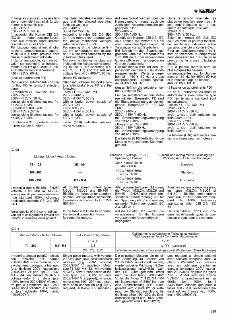
Motore / Motor / Motor / Moteur Poli / Pole / Polig / Pôles Collegamento avvolgimento /Winding connectionWicklungsanschlubß / Connexion du bobinage
71 - 250 M2 - M4
2, 4, 6 / Y2/4 YY (Dahlander)
2/6, 2/8, 2/12 Y/Y(due avvolgimenti / Two windings / zwei Wicklungen / Deux bobinage)
(C11)
I motori a singola polarità richiesticon tensione nel campo200�V�346V sono realizzati conavvolgimento collegato a triangolo(p.e. richiesto 200V, esecuzione200/346Y V); per i tipi 71 - 132,M1 - M4 con tensioni V�346V ilcollegamento è a stella (p.e.400V, fornito 230/400Y V), men-tre per le grandezze 160 - 250,l’esecuzione standard e’ a triango-lo (p.e. richiesto 400V, fornito400/690Y V).
Die einpoligen Motoren, die mit ei-ner Spannung im Bereich von200�V�346V angefordert werden,werden mit einer Wicklung mit Dre-lecksschaltung verwirklicht (wer-den z.B. 200V gefordert, erhäitman die Ausführung 200/346YV); für die Typen 71-132, M1 - M4mit Spannungen V�346V hat maneine Sternschaltung (z.B. 400V,geliefert wird 230/400Y V), wäh-rend die Standardausführung fürdie Baugrößen 160 - 250, die Drei-ecksschaltung ist (z.B. 400V gefor-dert, geliefert wird 400/690Y V).
Les moteurs à simple polaritéavec tension comprise dans laplage 200V-346V sont réalisésavec un bobinage braché entriangle (ex.requis 200V, execu-tion 200/346Y V; pour les types71-132, M1-M4, avec des tensionV�346V le branchement est enétoille (ex. 400V, fourni230/400Y V)tandis que pour latailles 160 - 250, l'exécution stan-dard set en triangle (ex. 400V,fourni 400/690Y V).
Single poles motors, with voltage200�V�346V have delta-connectedwindings (e.g. 200V required,200/346Y V supplied). Motorsize 71-132, M1 - M4 with voltageV�346V have a connection of thestar type (e.g. 400V required,200/346Y V supplied), whereasmotor sizes 160 - 250 has a stan-dard delta connection (e.g. 400Vrequired, 400/690Y V supplied).
In targa sono indicati oltre alla ten-sione nominale i campi di funzio-namento consentiti p.e.:220 - 240V 380 - 415V Y, 50 Hz.In accordo alle Norme CEI 2-3,IEC 34-1 i motori possono funzio-nare alle tensioni sopra indicatecon tolleranza del ± 5%.Per funzionamento ai limiti di tolle-ranza la temperatura può supera-re di 10 K il limite previsto dallaclasse di isolamento adottata.In targa vengono indicati inoltre ivalori corrispondenti al funziona-mento a 60 Hz (p.e. 460Y, 60 Hz)ed il relativo campo di tensione:440 - 480VY, 60 Hz.
(esclusi autofrenanti FD)
Per i motori autofrenanti con fre-no tipo FD le tensioni standardsono:- grandezze 71 - 132, M2 - M4220V - 240V 380V - 415V Y, 50 Hzcon tensione di alimentazione fre-no 230V ± 10%.- grandezze 160 - 280380 - 415V ,50 Hzcon tensione di alimentazione fre-no 400V � 10%.La tabella (C10) riporta le tensio-ni previste per i motori.
The plate indicates the rated volt-age and the allowed operatingfields as well, e.g.:220-240V 380-415V Y/50 Hz.According to rules CEI 2-3, IEC34-1 the motors can operate withthe above mentioned voltageswith tolerances of ± 5%.For running at the tolerance lim-its, the temperature can exceedof 10 K the limit foreseen by theinsulation class used.Moreover on the name plate areindicated the values correspond-ing to the 60 Hz operating (i.e.460 Y, 60 Hz) and the relevantvoltage field, 440 - 480VY, 60 Hz.
(brake FD excluded)
Standard voltages for brake mo-tors with brake type FD are thefollowing:- size 71 - 132, M2 - M4220V - 240V 380V - 415V Y, 50 Hzwith a brake power supply of230V ± 10%.- size 160 - 280380V - 415V ,50 Hzwith a brake power supply of400V � 10%.Table (C10) indicates relevantmotor voltages.
Auf dem Schild werden über dieNennspannung hinaus, auch diezulässigen Ansprechbereiche an-gegeben, z.B.:220-240V 380-415V Y/50 Hz.Gemäß den Normen CEI 2-3, IEC34-1 können die Motoren auf dieoben genannten Spannungen mitToleranzen von ± 5% arbeiten.Bei Betrieb an den Spannungs-grenzen, kann die Temperatur biszum 10K die für die verwendetenIsolierstoffklasse angegebenenGrenze überschreiten.Darüber hinaus wird auf den Ty-pensschild die dem 60 Hz-Betriebentsprechenden Werte angege-ben (d.h. 460 Y, 60 Hz) und dasentsprechende Spannungsfeld,440-480VY, 60 Hz.
(ausschließlich die selbstbremse-den Versionen FD).
Für die selbstbremsenden Moto-ren mit dem Bremsetyp FD sinddie Standardspannungen die fol-gende: - Baugrößen 71 - 132, M2- M4220V - 240V 380V - 415V Y /50 Hzmit Bremsspannungsversorgungvon 230V ± 10%.- Baugrößen 160 - 280380V - 415V Y/50 Hzmit Bremsspannungsversorgungvon 400V ± 10%.
Die tabelle (C10) fürth die für dieMotoren vorgesehenen Spannun-gen auf.
Outre la tension nominale, lesplages de fonctionnement permi-ses sont indiquées sur la pla-quette signalètique, à savoir:220-240V 380-415V Y/50 Hz.Selon les normes CEI 2-3, IEC34-1 les moteurs peuvent fonction-ner aux tension indiquées ci-des-sus avec une tolérance de ± 5%.Pour un fonctionnement à la li-mite de tolérance, la températurepeut dépasser les 10K, la limiteprevue de la classe d’isolationchoisie.Sur la plaque marque sont deplus indiqués les valeurscorrespondantes au fonctionne-ment en 60 Hz (ex.460Y, 60 Hz)et la relative plage de tension:440 - 480VY, 60 Hz.
(à l'exclusion autofreinants FD)
En ce qui concerne les moteursautofreinants avec frein de typeFD, les tensions standard sontles suivantes:- tailles 71 - 132, M2 - M4220V - 240V 380V - 415V Y /50 Hzavec tension d’alimentation dufrein 230V ± 10%.- taille 160 - 280380V - 415V Y /50 Hzavec tension d’alimentation dufrein 400V ± 10%.
La tableau (C10) indique les ten-sions prévues pour les moteurs.
Motore / Motor / Motor / Moteur Tensione / Voltage (� 10%)Spannung / Tension
Esecuzione avvolgimento / Winding typeWicklungsart / Exécution bobinage
71 - 132 M2 - M4 230 / 400Y, 50 Hz.460Y 60Hz Standard
160 -280 — 400 / 690Y 50Hz460 60 Hz Standard
100 - 132 M3 - M 4 400 / 690Y 50Hz460 60 Hz A richiesta
(C10)
I motori a due e BN160 - BN250velocità, i tipi M3LC4, M3LC6,sono previsti per tensione nomi-nale standard 400V; tolleranzeapplicabili secondo CEI 2-3, IEC34-1.
Nella tabella (C11) sono indicati ivari tipi di collegamenti previsti peri motori in funzione della polarità.
All double speed motors typesM3LC4, M3LC6 and BN160 -BN250, are foreseen for standardnominal voltage 400V; applicabletolerances according to CEI 2-3,IEC 34-1.
In the table (C11) are to be foundthe several connection typesforeseen for motors.
Alle polumschaltbaren Motoren,die Typen M3LC4, M3LC6 undBN160 - BN250,sind nicht um-schaltbar, standardmä�ig nur fürein Spannung 400V vorgesehen;geltenden Toleranzen gemä� IEC2-3, CEI 34-1.
Auf die Tabelle (C11) werden dieverschiedenen für die Motorenvorgesehenen Anschlußtypenangegeben.
Tous les moteur à deux vitesses,les types M3LC4, M3LC6 etBN160 - BN250, sont prevuspour une tension nominale stan-dard de 400V; tolérancesapplicables selon CEI 2-3, IEC34-1.
Dans le tableau (C11) sont indi-qués les differents types de con-nexion prevus pour les moteurs.
330
A richiesta, per tensioni V�346V imotori 100 - 132, M3 - M4 posso-no essere forniti con collegamen-to a triangolo; in questo caso do-vrà essere sempre indicato in de-signazione anche il corrisponden-te valore a stella (p.e. richiesto400V , indicare 400/690V).I motori a due velocità 71-90, M2sono disponibili con tensioni com-prese tra 200 - 500V; per le altregrandezze le tensioni previstesono tra 200 - 690V (collegamen-ti come in tab. C11).
I motori grandezza 100 - 250, M3- M4 a due velocità (escluso 2/4poli), a richiesta possono essereforniti con morsettiera a 12 mor-setti; solo in questo caso specifi-care in designazione entrambe letensioni (p.e. richiesto 400V , in-dicare 400/690V).
Per l’alimentazione dell’eventua-le freno fare riferimento al para-grafo 6.2 e 6.3.
Auf Anfrage können SpannungenV�346V die Motoren 100 - 132,M3 - M4 mit einer Dreiecksschal-tung geliefert werden; in diesemFall muß in der Bezeichnung im-mer auch der entsprechendeSternwert ange geben werden(z.B. bei erforderlichen 400V �ist 400/690V angeben).
Die Motoren mit zwei Geschwin-digkeiten 71 - 90, M2 sind mitSpannungen zwischen 200 -500V verfügbar, bei den anderenBau- grö�en sind Spannungenzwischen 200 - 690V vorgesehen(Schaltungen gemä� Tab. C11)Die Motoren mit zwei Geschwin-digkeiten 100 - 250, M3 - M4(ausgenommen 2/4 Pole) könnenauf Anfrage mit einem, mit 12klemmen ausgestatteten Klem-menbrett geliefert werden; nur indiesem Fall müssen in der Be-zeichnung beide Spannungenspezifiziert werden (z.B. 400Vgefordert, ist 400/690V anzuge-ben).
Für die Versorgung der eventuellvorhandenen Bremse, ist Bezugauf den Par. 6.2 und 6.3 zu neh-men.
Sur demande, pour des tensionsV�346V les moteurs 100-132, M3- M4 peuvent être fournis avec unbranchement en triangle; dans cecas, la valeur correspondante enétoile (ex. requis 400V , indiquer400/690V) doit toujours être in-diquée dans la désignation.Les moteurs à deux vitesses 71 -90, M2 sont disponibles avec destensions comprises entre 200 -500V; pour les autres tailles lestensions prevues sont comprisesentre 200 et 690V (branchementsvoir tab. C11.)
Les moteurs taille 100 - 250, M3 -M4 à deux vitasses (sauf 2/4 po-les) peuvent être fournis sur de-mande avec à bornier à 12 bor-nes; uniquemant dans ce cas,spècifier les deux tensions dansla dèsignation (ex. requis 400V ,indiquer 400/690V).
En ce qui concerne l’alimentationde l’éventuel frein, se référer auparagraphe 6.2 et 6.3.
On request for voltages V�346Vmotors 100-132, M3 - M4 can besupplied with delta connection. Inthis case, corresponding starvalue should always be indicatedin the relevant description (e.g.for 400V required� indicate400/690V ).Double polarity motors 71-90, M2are avalaible with voltages within200 - 500V. For other sizes volt-ages are within 200 - 690V (forconnection see table C11).
On request double polarity mo-tors, sizes 100-250, M3 - M4 (2/4poles excluded) can be suppliedwith a 12-terminal terminal box.Only in this case specify bothvoltage in relevant decription(e.g. for 400V required, indicate400/690V).
As for brake power supply, referto paragraph 6.2 and 6.3.
30.5.2 Frequenza
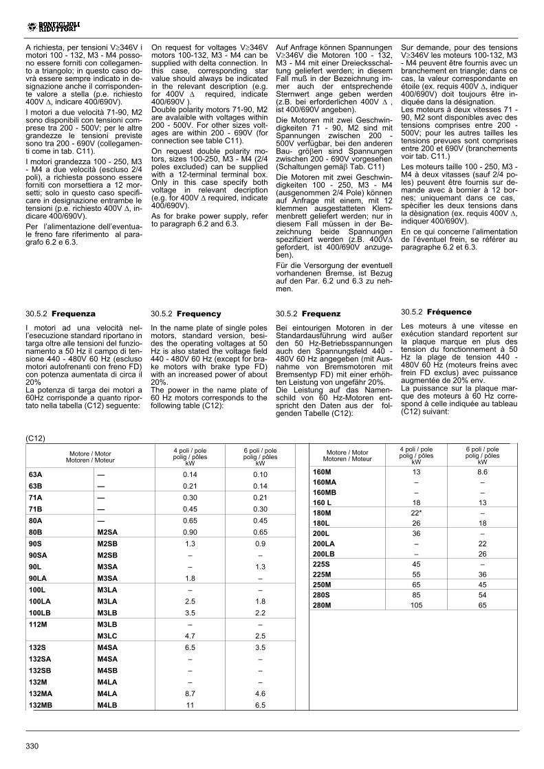
I motori ad una velocità nel-l’esecuzione standard riportano intarga oltre alle tensioni del funzio-namento a 50 Hz il campo di ten-sione 440 - 480V 60 Hz (esclusomotori autofrenanti con freno FD)con potenza aumentata di circa il20%La potenza di targa dei motori a60Hz corrisponde a quanto ripor-tato nella tabella (C12) seguente:
30.5.2 Frequenz
Bei eintourigen Motoren in derStandardausführung wird außerden 50 Hz-Betriebsspannungenauch den Spannungsfeld 440 -480V 60 Hz angegeben (mit Aus-nahme von Bremsmotoren mitBremsentyp FD) mit einer erhöh-ten Leistung von ungefähr 20%.Die Leistung auf das Namen-schild von 60 Hz-Motoren ent-spricht den Daten aus der fol-genden Tabelle (C12):
30.5.2 Fréquence
Les moteurs à une vitesse enexécution standard reportent surla plaque marque en plus destension du fonctionnement à 50Hz la plage de tension 440 -480V 60 Hz (moteurs freins avecfrein FD exclus) avec puissanceaugmentée de 20% env.La puissance sur la plaque mar-que des moteurs à 60 Hz corre-spond à celle indiquée au tableau(C12) suivant:
30.5.2 Frequency
In the name plate of single polesmotors, standard version, besi-des the operating voltages at 50Hz is also stated the voltage field440 - 480V 60 Hz (except for bra-ke motors with brake type FD)with an increased power of about20%.The power in the name plate of60 Hz motors corresponds to thefollowing table (C12):
(C12)
Motore / MotorMotoren / Moteur
4 poli / polepolig / pôles
kW
6 poli / polepolig / pôles
kW
160M 13 8.6
160MA – –
160MB – –
160 L 18 13
180M 22* –
180L 26 18
200L 36 –
200LA – 22
200LB – 26
225S 45 –
225M 55 36
250M 65 45
280S 85 54
280M 105 65
Motore / MotorMotoren / Moteur
4 poli / polepolig / pôles
kW
6 poli / polepolig / pôles
kW
63A — 0.14 0.10
63B — 0.21 0.14
71A — 0.30 0.21
71B — 0.45 0.30
80A — 0.65 0.45
80B M2SA 0.90 0.65
90S M2SB 1.3 0.9
90SA M2SB – –
90L M3SA – 1.3
90LA M3SA 1.8 –
100L M3LA – –
100LA M3LA 2.5 1.8
100LB M3LB 3.5 2.2
112M M3LB – –
M3LC 4.7 2.5
132S M4SA 6.5 3.5
132SA M4SA – –
132SB M4SB – –
132M M4LA – –
132MA M4LA 8.7 4.6
132MB M4LB 11 6.5
331
(C15)
* Escluso motori autofrenanti FA** Escluso motori autofrenanti FD.
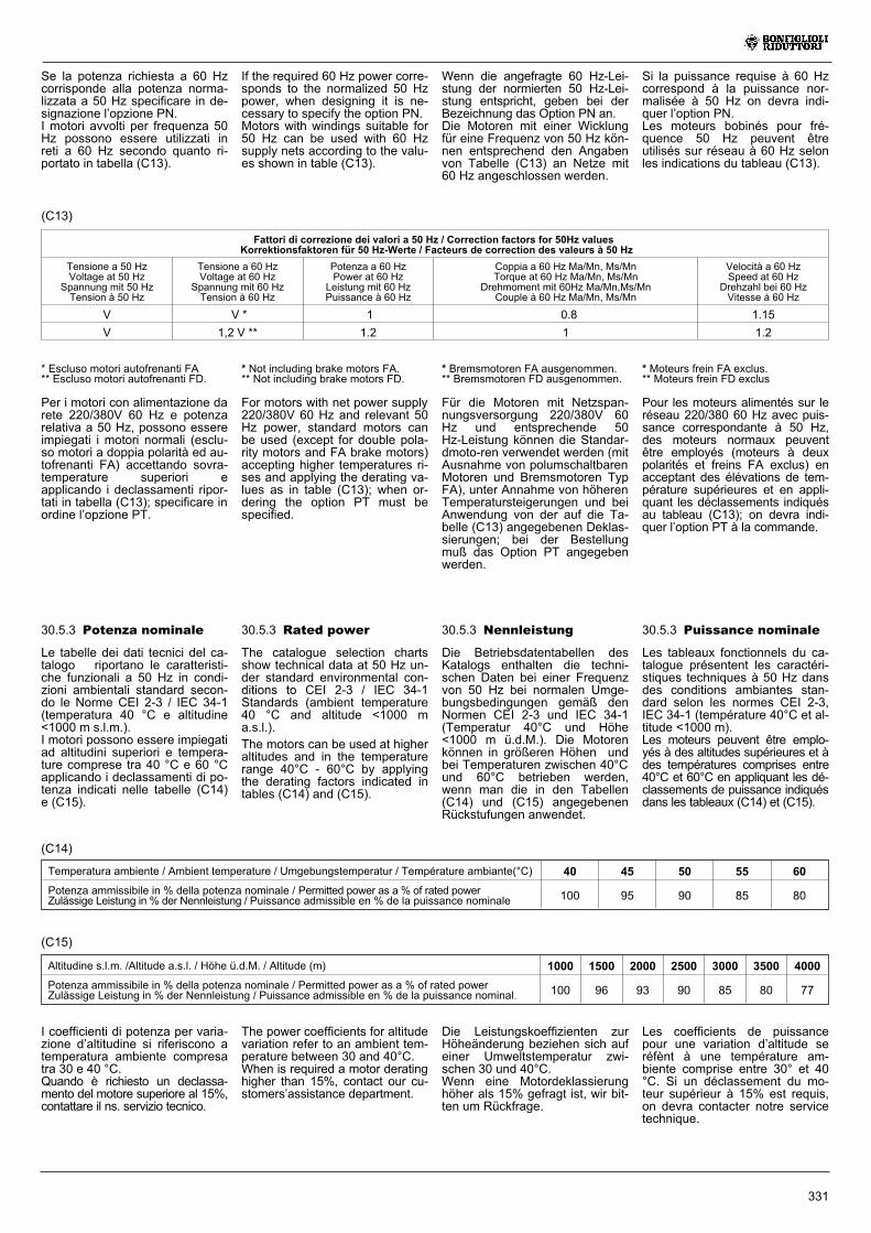
Per i motori con alimentazione darete 220/380V 60 Hz e potenzarelativa a 50 Hz, possono essereimpiegati i motori normali (esclu-so motori a doppia polarità ed au-tofrenanti FA) accettando sovra-temperature superiori eapplicando i declassamenti ripor-tati in tabella (C13); specificare inordine l’opzione PT.
I coefficienti di potenza per varia-zione d’altitudine si riferiscono atemperatura ambiente compresatra 30 e 40 °C.Quando è richiesto un declassa-mento del motore superiore al 15%,contattare il ns. servizio tecnico.
30.5.3 Potenza nominale
Le tabelle dei dati tecnici del ca-talogo riportano le caratteristi-che funzionali a 50 Hz in condi-zioni ambientali standard secon-do le Norme CEI 2-3 / IEC 34-1(temperatura 40 °C e altitudine<1000 m s.l.m.).I motori possono essere impiegatiad altitudini superiori e tempera-ture comprese tra 40 °C e 60 °Capplicando i declassamenti di po-tenza indicati nelle tabelle (C14)e (C15).
Temperatura ambiente / Ambient temperature / Umgebungstemperatur / Température ambiante(°C) 40 45 50 55 60
Potenza ammissibile in % della potenza nominale / Permitted power as a % of rated powerZulässige Leistung in % der Nennleistung / Puissance admissible en % de la puissance nominale 100 95 90 85 80
(C14)
* Bremsmotoren FA ausgenommen.** Bremsmotoren FD ausgenommen.
Für die Motoren mit Netzspan-nungsversorgung 220/380V 60Hz und entsprechende 50Hz-Leistung können die Standar-dmoto-ren verwendet werden (mitAusnahme von polumschaltbarenMotoren und Bremsmotoren TypFA), unter Annahme von höherenTemperatursteigerungen und beiAnwendung von der auf die Ta-belle (C13) angegebenen Deklas-sierungen; bei der Bestellungmuß das Option PT angegebenwerden.
* Moteurs frein FA exclus.** Moteurs frein FD exclus
Pour les moteurs alimentés sur leréseau 220/380 60 Hz avec puis-sance correspondante à 50 Hz,des moteurs normaux peuventêtre employés (moteurs à deuxpolarités et freins FA exclus) enacceptant des élévations de tem-pérature supérieures et en appli-quant les déclassements indiquésau tableau (C13); on devra indi-quer l’option PT à la commande.
* Not including brake motors FA.** Not including brake motors FD.
For motors with net power supply220/380V 60 Hz and relevant 50Hz power, standard motors canbe used (except for double pola-rity motors and FA brake motors)accepting higher temperatures ri-ses and applying the derating va-lues as in table (C13); when or-dering the option PT must bespecified.
30.5.3 Nennleistung
Die Betriebsdatentabellen desKatalogs enthalten die techni-schen Daten bei einer Frequenzvon 50 Hz bei normalen Umge-bungsbedingungen gemäß denNormen CEI 2-3 und IEC 34-1(Temperatur 40°C und Höhe<1000 m ü.d.M.). Die Motorenkönnen in größeren Höhen undbei Temperaturen zwischen 40°Cund 60°C betrieben werden,wenn man die in den Tabellen(C14) und (C15) angegebenenRückstufungen anwendet.
30.5.3 Puissance nominale
Les tableaux fonctionnels du ca-talogue présentent les caractéri-stiques techniques à 50 Hz dansdes conditions ambiantes stan-dard selon les normes CEI 2-3,IEC 34-1 (température 40°C et al-titude <1000 m).Les moteurs peuvent être emplo-yés à des altitudes supérieures et àdes températures comprises entre40°C et 60°C en appliquant les dé-classements de puissance indiquésdans les tableaux (C14) et (C15).
30.5.3 Rated power
The catalogue selection chartsshow technical data at 50 Hz un-der standard environmental con-ditions to CEI 2-3 / IEC 34-1Standards (ambient temperature40 °C and altitude <1000 ma.s.l.).
The motors can be used at higheraltitudes and in the temperaturerange 40°C - 60°C by applyingthe derating factors indicated intables (C14) and (C15).
Altitudine s.l.m. /Altitude a.s.l. / Höhe ü.d.M. / Altitude (m) 1000 1500 2000 2500 3000 3500 4000
Potenza ammissibile in % della potenza nominale / Permitted power as a % of rated powerZulässige Leistung in % der Nennleistung / Puissance admissible en % de la puissance nominal. 100 96 93 90 85 80 77
Se la potenza richiesta a 60 Hzcorrisponde alla potenza norma-lizzata a 50 Hz specificare in de-signazione l’opzione PN.I motori avvolti per frequenza 50Hz possono essere utilizzati inreti a 60 Hz secondo quanto ri-portato in tabella (C13).
(C13)
If the required 60 Hz power corre-sponds to the normalized 50 Hzpower, when designing it is ne-cessary to specify the option PN.Motors with windings suitable for50 Hz can be used with 60 Hzsupply nets according to the valu-es shown in table (C13).
Wenn die angefragte 60 Hz-Lei-stung der normierten 50 Hz-Lei-stung entspricht, geben bei derBezeichnung das Option PN an.Die Motoren mit einer Wicklungfür eine Frequenz von 50 Hz kön-nen entsprechend den Angabenvon Tabelle (C13) an Netze mit60 Hz angeschlossen werden.
Si la puissance requise à 60 Hzcorrespond à la puissance nor-malisée à 50 Hz on devra indi-quer l’option PN.Les moteurs bobinés pour fré-quence 50 Hz peuvent êtreutilisés sur réseau à 60 Hz selonles indications du tableau (C13).
The power coefficients for altitudevariation refer to an ambient tem-perature between 30 and 40°C.When is required a motor deratinghigher than 15%, contact our cu-stomers’assistance department.
Die Leistungskoeffizienten zurHöheänderung beziehen sich aufeiner Umweltstemperatur zwi-schen 30 und 40°C.Wenn eine Motordeklassierunghöher als 15% gefragt ist, wir bit-ten um Rückfrage.
Les coefficients de puissancepour une variation d’altitude seréfènt à une température am-biente comprise entre 30° et 40°C. Si un déclassement du mo-teur supérieur à 15% est requis,on devra contacter notre servicetechnique.
Fattori di correzione dei valori a 50 Hz / Correction factors for 50Hz valuesKorrektionsfaktoren für 50 Hz-Werte / Facteurs de correction des valeurs à 50 Hz
Tensione a 50 HzVoltage at 50 Hz
Spannung mit 50 HzTension à 50 Hz
Tensione a 60 HzVoltage at 60 Hz
Spannung mit 60 HzTension à 60 Hz
Potenza a 60 HzPower at 60 Hz
Leistung mit 60 HzPuissance à 60 Hz
Coppia a 60 Hz Ma/Mn, Ms/MnTorque at 60 Hz Ma/Mn, Ms/Mn
Drehmoment mit 60Hz Ma/Mn,Ms/MnCouple à 60 Hz Ma/Mn, Ms/Mn
Velocità a 60 HzSpeed at 60 Hz
Drehzahl bei 60 HzVitesse à 60 Hz
V V * 1 0.8 1.15
V 1,2 V ** 1.2 1 1.2
332
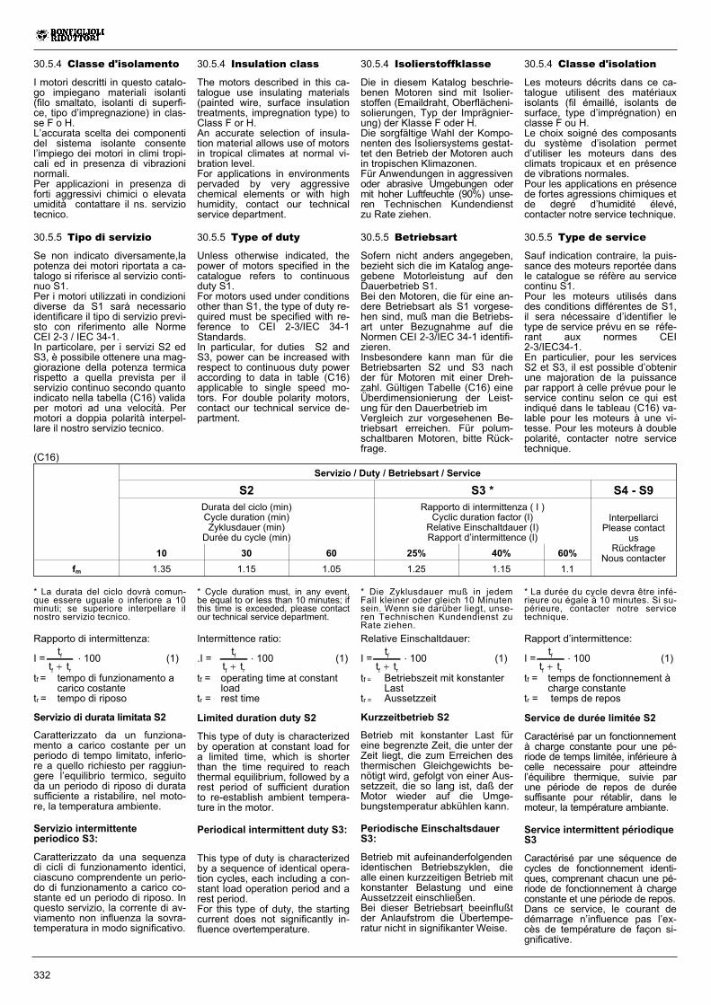
Servizio / Duty / Betriebsart / Service
S2 S3 * S4 - S9Durata del ciclo (min)Cycle duration (min)Zyklusdauer (min)Durée du cycle (min)
Rapporto di intermittenza ( I )Cyclic duration factor (I)Relative Einschaltdauer (I)Rapport d’intermittence (l)
InterpellarciPlease contact
usRückfrage
Nous contacter10 30 60 25% 40% 60%
fm 1.35 1.15 1.05 1.25 1.15 1.1
Rapporto di intermittenza:
I =t
t tf
f r�. 100 (1)
tf = tempo di funzionamento acarico costante
tr = tempo di riposo
Servizio di durata limitata S2
Caratterizzato da un funziona-mento a carico costante per unperiodo di tempo limitato, inferio-re a quello richiesto per raggiun-gere l’equilibrio termico, seguitoda un periodo di riposo di duratasufficiente a ristabilire, nel moto-re, la temperatura ambiente.
Servizio intermittenteperiodico S3:
Caratterizzato da una sequenzadi cicli di funzionamento identici,ciascuno comprendente un perio-do di funzionamento a carico co-stante ed un periodo di riposo. Inquesto servizio, la corrente di av-viamento non influenza la sovra-temperatura in modo significativo.
(C16)
30.5.5 Tipo di servizio
Se non indicato diversamente,lapotenza dei motori riportata a ca-talogo si riferisce al servizio conti-nuo S1.Per i motori utilizzati in condizionidiverse da S1 sarà necessarioidentificare il tipo di servizio previ-sto con riferimento alle NormeCEI 2-3 / IEC 34-1.In particolare, per i servizi S2 edS3, è possibile ottenere una mag-giorazione della potenza termicarispetto a quella prevista per ilservizio continuo secondo quantoindicato nella tabella (C16) validaper motori ad una velocità. Permotori a doppia polarità interpel-lare il nostro servizio tecnico.
* La durata del ciclo dovrà comun-que essere uguale o inferiore a 10minuti; se superiore interpellare ilnostro servizio tecnico.
30.5.5 Betriebsart
Sofern nicht anders angegeben,bezieht sich die im Katalog ange-gebene Motorleistung auf denDauerbetrieb S1.Bei den Motoren, die für eine an-dere Betriebsart als S1 vorgese-hen sind, muß man die Betriebs-art unter Bezugnahme auf dieNormen CEI 2-3/IEC 34-1 identifi-zieren.Insbesondere kann man für dieBetriebsarten S2 und S3 nachder für Motoren mit einer Dreh-zahl. Gültigen Tabelle (C16) eineÜberdimensionierung der Leist-ung für den Dauerbetrieb imVergleich zur vorgesehenen Be-triebsart erreichen. Für polum-schaltbaren Motoren, bitte Rück-frage.
30.5.5 Type de service
Sauf indication contraire, la puis-sance des moteurs reportée dansle catalogue se réfère au servicecontinu S1.Pour les moteurs utilisés dansdes conditions différentes de S1,il sera nécessaire d’identifier letype de service prévu en se réfe-rant aux normes CEI2-3/IEC34-1.En particulier, pour les servicesS2 et S3, il est possible d’obtenirune majoration de la puissancepar rapport à celle prévue pour leservice continu selon ce qui estindiqué dans le tableau (C16) va-lable pour les moteurs à une vi-tesse. Pour les moteurs à doublepolarité, contacter notre servicetechnique.
30.5.5 Type of duty
Unless otherwise indicated, thepower of motors specified in thecatalogue refers to continuousduty S1.For motors used under conditionsother than S1, the type of duty re-quired must be specified with re-ference to CEI 2-3/IEC 34-1Standards.In particular, for duties S2 andS3, power can be increased withrespect to continuous duty poweraccording to data in table (C16)applicable to single speed mo-tors. For double polarity motors,contact our technical service de-partment.
* Die Zyklusdauer muß in jedemFall kleiner oder gleich 10 Minutensein. Wenn sie darüber liegt, unse-ren Technischen Kundendienst zuRate ziehen.
* La durée du cycle devra être infé-rieure ou égale à 10 minutes. Si su-périeure, contacter notre servicetechnique.
* Cycle duration must, in any event,be equal to or less than 10 minutes; ifthis time is exceeded, please contactour technical service department.
Relative Einschaltdauer:
I =t
t tf
f r�. 100 (1)
tf = Betriebszeit mit konstanterLast
tr = Aussetzzeit
Kurzzeitbetrieb S2
Betrieb mit konstanter Last füreine begrenzte Zeit, die unter derZeit liegt, die zum Erreichen desthermischen Gleichgewichts be-nötigt wird, gefolgt von einer Aus-setzzeit, die so lang ist, daß derMotor wieder auf die Umge-bungstemperatur abkühlen kann.
Periodische EinschaltsdauerS3:
Betrieb mit aufeinanderfolgendenidentischen Betriebszyklen, diealle einen kurzzeitigen Betrieb mitkonstanter Belastung und eineAussetzzeit einschließen.Bei dieser Betriebsart beeinflußtder Anlaufstrom die Übertempe-ratur nicht in signifikanter Weise.
Rapport d’intermittence:
I =t
t tf
f r�. 100 (1)
tf = temps de fonctionnement àcharge constante
tr = temps de repos
Service de durée limitée S2
Caractérisé par un fonctionnementà charge constante pour une pé-riode de temps limitée, inférieure àcelle necessaire pour atteindrel’équilibre thermique, suivie parune période de repos de duréesuffisante pour rétablir, dans lemoteur, la température ambiante.
Service intermittent périodiqueS3
Caractérisé par une séquence decycles de fonctionnement identi-ques, comprenant chacun une pé-riode de fonctionnement à chargeconstante et une période de repos.Dans ce service, le courant dedémarrage n’influence pas l’ex-cès de température de façon si-gnificative.
Intermittence ratio:
.I =t
t tf
f r�. 100 (1)
tf = operating time at constantload
tr = rest time
Limited duration duty S2
This type of duty is characterizedby operation at constant load fora limited time, which is shorterthan the time required to reachthermal equilibrium, followed by arest period of sufficient durationto re-establish ambient tempera-ture in the motor.
Periodical intermittent duty S3:
This type of duty is characterizedby a sequence of identical opera-tion cycles, each including a con-stant load operation period and arest period.For this type of duty, the startingcurrent does not significantly in-fluence overtemperature.
30.5.4 Classe d'isolamento
I motori descritti in questo catalo-go impiegano materiali isolanti(filo smaltato, isolanti di superfi-ce, tipo d’impregnazione) in clas-se F o H.L’accurata scelta dei componentidel sistema isolante consentel’impiego dei motori in climi tropi-cali ed in presenza di vibrazioninormali.Per applicazioni in presenza diforti aggressivi chimici o elevataumidità contattare il ns. serviziotecnico.
30.5.4 Isolierstoffklasse
Die in diesem Katalog beschrie-benen Motoren sind mit Isolier-stoffen (Emaildraht, Oberflächeni-solierungen, Typ der Imprägnier-ung) der Klasse F oder H.Die sorgfältige Wahl der Kompo-nenten des Isoliersystems gestat-tet den Betrieb der Motoren auchin tropischen Klimazonen.Für Anwendungen in aggressivenoder abrasive Umgebungen odermit hoher Luftfeuchte (90%) unse-ren Technischen Kundendienstzu Rate ziehen.
30.5.4 Classe d'isolation
Les moteurs décrits dans ce ca-talogue utilisent des matériauxisolants (fil émaillé, isolants desurface, type d’imprégnation) enclasse F ou H.Le choix soigné des composantsdu système d’isolation permetd’utiliser les moteurs dans desclimats tropicaux et en présencede vibrations normales.Pour les applications en présencede fortes agressions chimiques etde degré d’humidité élevé,contacter notre service technique.
30.5.4 Insulation class
The motors described in this ca-talogue use insulating materials(painted wire, surface insulationtreatments, impregnation type) toClass F or H.An accurate selection of insula-tion material allows use of motorsin tropical climates at normal vi-bration level.For applications in environmentspervaded by very aggressivechemical elements or with highhumidity, contact our technicalservice department.
333
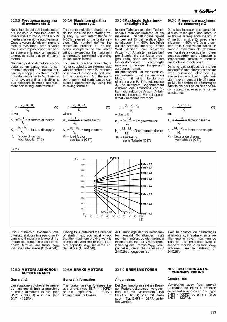
30.5.6 Frequenza massimadi avviamento Z
Nelle tabelle dei dati tecnici moto-ri è indicata la max frequenza diinserzione a vuoto Z0 con I = 50%riferita alla versione autofrenante.Questo valore definisce il numeromax di avviamenti orari a vuotoche il motore può sopportare sen-za superare la max temperaturaammessa dalla classe di isola-mento F.
Nel caso pratico di motore accop-piato ad un carico esterno conpotenza assorbita Pr, massa iner-ziale Jc e coppia resistente mediadurante l’avviamento ML, il nume-ro di avviamenti ammissibile sipuò calcolare in modo approssi-mato con la seguente formula:
Z =Z K K
K0 c d
J
(2)
dove:
K =J +J
JJm c
m
= fattore di inerzia
K =M -M
Mca L
a
= fattore di coppia
Kd � fattore di caricovedi tabella (C17)
Con il numero di avviamenti cosìottenuto si dovrà in seguito verifi-care che il massimo lavoro di fre-natura sia compatibile con la ca-pacità termica del freno Wmaxindicata nelle tabelle (C 24-C28).
(C17)
30.5.6Maximale Schaltung-shäufigkeit Z
In den Tabellen mit den Techni-schen Daten der Motoren ist diemaximale Schaltungshäufigkeitim Leerlauf Z0 bei relativer Ein-schaltdauer I = 50% bezüglichauf die Bremsausführung. DieserWert definiert die maximaleAnzahl von Anfahrten im Leerlaufpro Stunde, die der Motor ertra-gen kann, ohne die durch dieIsolierstoffklasse F festgelegtemaximal zulässige Temperaturzu überschreiten.Im praktischen Fall eines mit ei-ner externen Last verbundenenMotors mit einer Leistungsa-uf-nahme von Pr, TrägheitsmasseJc und mittlerem Gegenmomentwährend des Anfahrens von MLkann die zulässige Anzahl Anfah-rten mit folgender Formel appro-ximativ berechnet werden:
Z =Z K K
K0 c d
J
(2)
wobei gilt:
K =J +J
JJm c
m
= Trägheitsfaktor
K =M -M
Mca L
a
=Drehmomentsfaktor
Kd = Lastfaktorsiehe Tabelle (C17)
30.5.6 Fréquence maximumde démarrage Z
Dans les tableaux des caractéri-stiques techniques des moteursse trouve la fréquence maximumd’insertion à vide Z0 avec inter-mittence I = 50% référée à la ver-sion frein. Cette valeur définit unnombre maximum de démarra-ges horaires à vide que le moteurpeut supporter sans dépasser latempérature maximum admisepar la classe d’isolation F.
Dans le cas pratique de moteuraccouplé à une charge extérieureavec puissance absorbée Pr,masse inertielle Jc et couple rési-stant moyen pendant le démarra-ge ML, le nombre de démarragesadmissible peut se calculer de fa-çon approximative avec la formu-le suivante:
Z =Z K K
K0 c d
J
(2)
où:
K =J +J
JJm c
m
= facteur d’inertie
K =M -M
Mca L
a
= facteur de couple
Kd = facteur de chargevoir tableau (C17)
30.5.6 Maximum startingfrequency Z
The motor selection charts inclu-de the max. no-load starting fre-quency Z0 with intermittence ofI=50% referred to the brake ver-sion. This number defines themaximum number of no-loadstarts acceptable to the motorwithout exceeding the maximumtemperature permitted accordingto insulation class F.
To give a practical example, amotor coupled to an external loadwith absorbed power Pr, momentof inertia of masses Jc and loadtorque during start ML, the num-ber of permitted starts can be cal-culated approximately using thefollowing formula:
Z =Z K K
K0 c d
J
(2)
where:
K =J +J
JJm c
m
=inertia factor
K =M -M
Mca L
a
= torque factor
Kd = load factorsee table (C17)
Auf Grundlage der so berechne-ten Anzahl Schaltungen mußman dann prüfen, ob die maximaleBremsarbeit mit der Wärmegren-zleistung der Bremse Wmax kom-patibel ist, die in die Tabellen (C24-C28) angegeben ist.
Avec le nombre de démarragesainsi obtenu, il faudra ensuite vé-rifier que le travail maximum defreinage soit compatible avec lacapacité thermique du frein Wmaxindiquée dans le tableaux (C24-C28).
Having thus obtained the numberof starts, next you must checkthat the maximum braking work iscompatible with the brake’s ther-mal capacity Wmax indicated un-der tables (C 24-C28).
30.6.0 BRAKE MOTORS
General information
The brake version foresees theuse of d.c. (type BN71 - 160FD)or a.c. (type BN71 - 132FA)spring pressure brakes.
30.6.0 BREMSMOTOREN
Allgemeines
Bei Bremsmotoren sind als Brem-se Federdruckbremse vorgese-hen, die mit Gleichstrom (TypBN71 - 160FD) oder mit Dreh-strom (Typ BN71 - 132FA) gelie-fert werden.
30.6.0 MOTEURS ASYN-CHRONES FREINS
Généralités
L’exécution avec frein prevoitl’utilisation de freins à pressionde ressort alimentés en c.c. (typeBN71 - 160FD) ou en c.a. (typeBN71 - 132FA).
30.6.0 MOTORI ASINCRONIAUTOFRENANTI
Generalità
L’esecuzione autofrenante preve-de l’impiego di freni a pressionedi molle alimentati in c.c. (tipoBN71 - 160FD) o in c.a. (tipoBN71 - 132FA).
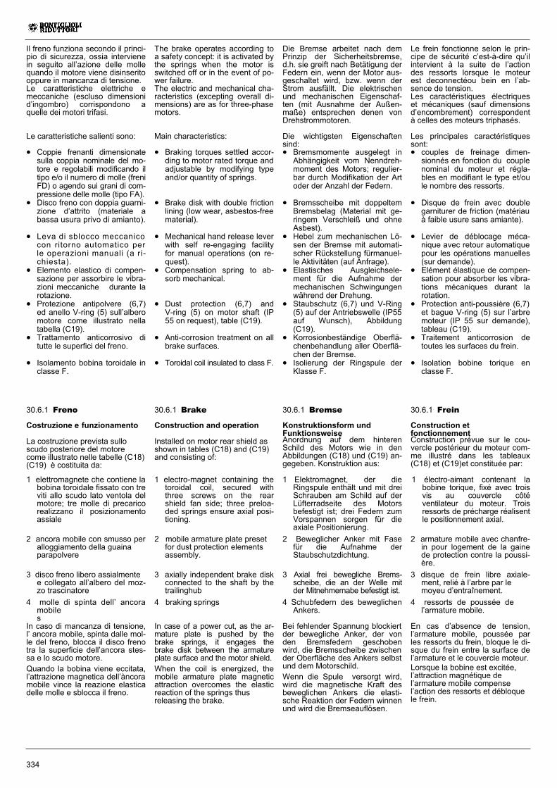
334
Il freno funziona secondo il princi-pio di sicurezza, ossia intervienein seguito all’azione delle mollequando il motore viene disinseritooppure in mancanza di tensione.Le caratteristiche elettriche emeccaniche (escluso dimensionid’ingombro) corrispondono aquelle dei motori trifasi.
Le caratteristiche salienti sono:
� Coppie frenanti dimensionatesulla coppia nominale del mo-tore e regolabili modificando iltipo e/o il numero di molle (freniFD) o agendo sui grani di com-pressione delle molle (tipo FA).
� Disco freno con doppia guarni-zione d’attrito (materiale abassa usura privo di amianto).
� Leva di sblocco meccanicocon ritorno automatico perle operazioni manuali (a ri-chiesta).
� Elemento elastico di compen-sazione per assorbire le vibra-zioni meccaniche durante larotazione.
� Protezione antipolvere (6,7)ed anello V-ring (5) sull’alberomotore come illustrato nellatabella (C19).
� Trattamento anticorrosivo ditutte le superfici del freno.
� Isolamento bobina toroidale inclasse F.
30.6.1 Freno
Costruzione e funzionamento
La costruzione prevista sulloscudo posteriore del motorecome illustrato nelle tabelle (C18)(C19) è costituita da:
1 elettromagnete che contiene labobina toroidale fissato con treviti allo scudo lato ventola delmotore; tre molle di precaricorealizzano il posizionamentoassiale
2 ancora mobile con smusso peralloggiamento della guainaparapolvere
3 disco freno libero assialmentee collegato all’albero del moz-zo trascinatore
4 molle di spinta dell’ ancoramobiles
In caso di mancanza di tensione,l’ ancora mobile, spinta dalle mol-le del freno, blocca il disco frenotra la superficie dell’ancora stes-sa e lo scudo motore.
Quando la bobina viene eccitata,l’attrazione magnetica dell’àncoramobile vince la reazione elasticadelle molle e sblocca il freno.
Die Bremse arbeitet nach demPrinzip der Sicherheitsbremse,d.h. sie greift nach Betätigung derFedern ein, wenn der Motor aus-geschaltet wird, bzw. wenn derStrom ausfällt. Die elektrischenund mechanischen Eigenschaf-ten (mit Ausnahme der Außen-maße) entsprechen denen vonDrehstrommotoren.
Die wichtigsten Eigenschaftensind:� Bremsmomente ausgelegt inAbhängigkeit vom Nenndreh-moment des Motors; regulier-bar durch Modifikation der Artoder der Anzahl der Federn.
� Bremsscheibe mit doppeltemBremsbelag (Material mit ge-ringem Verschleiß und ohneAsbest).
� Hebel zum mechanischen Lö-sen der Bremse mit automati-scher Rückstellung fürmanuel-le Aktivitäten (auf Anfrage).
� Elastisches Ausgleichsele-ment für die Aufnahme dermechanischen Schwingungenwährend der Drehung.
� Staubschutz (6,7) und V-Ring(5) auf der Antriebswelle (IP55auf Wunsch), Abbildung(C19).
� Korrosionbeständige Oberflä-chenbehandlung aller Oberflä-chen der Bremse.
� Isolierung der Ringspule derKlasse F.
Le frein fonctionne selon le prin-cipe de sécurité c’est-à-dire qu’ilintervient à la suite de l’actiondes ressorts lorsque le moteurest deconnectéou bein en l’ab-sence de tension.Les caractéristiques électriqueset mécaniques (sauf dimensionsd’encombrement) correspondentà celles des moteurs triphasés.
Les principales caractéristiquessont:� couples de freinage dimen-sionnés en fonction du couplenominal du moteur et régla-bles en modifiant le type et/oule nombre des ressorts.
� Disque de frein avec doublegarniturer de friction (matériauà faible usure sans amiante).
� Levier de déblocage méca-nique avec retour automatiquepour les opérations manuelles(sur demande).
� Elément élastique de compen-sation pour absorber les vibra-tions mécaniques durant larotation.
� Protection anti-poussière (6,7)et bague V-ring (5) sur l’arbremoteur (IP 55 sur demande),tableau (C19).
� Traitement anticorrosion detoutes les surfaces du frein.
� Isolation bobine torique enclasse F.
The brake operates according toa safety concept: it is activated bythe springs when the motor isswitched off or in the event of po-wer failure.The electric and mechanical cha-racteristics (excepting overall di-mensions) are as for three-phasemotors.
Main characteristics:
� Braking torques settled accor-ding to motor rated torque andadjustable by modifying typeand/or quantity of springs.
� Brake disk with double frictionlining (low wear, asbestos-freematerial).
� Mechanical hand release leverwith self re-engaging facilityfor manual operations (on re-quest).
� Compensation spring to ab-sorb mechanical.
� Dust protection (6,7) andV-ring (5) on motor shaft (IP55 on request), table (C19).
� Anti-corrosion treatment on allbrake surfaces.
� Toroidal coil insulated to class F.
30.6.1 Frein
Construction etfonctionnementConstruction prévue sur le cou-vercle postérieur du moteur com-me illustré dans les tableaux(C18) et (C19)et constituée par:
1 électro-aimant contenant labobine torique, fixé avec troisvis au couvercle côtéventilateur du moteur. Troisressorts de précharge réalisentle positionnement axial.
2 armature mobile avec chanfre-in pour logement de la gainede protection contre la poussi-ère.
3 disque de frein libre axiale-ment, relié à l’arbre par lemoyeu d’entraînement.
4 ressorts de poussée del’armature mobile.
En cas d’absence de tension,l’armature mobile, poussée parles ressorts du frein, bloque le di-sque du frein entre la surface del’armature et le couvercle moteur.Lorsque la bobine est excitée,l’attraction magnétique del’armature mobile compensel’action des ressorts et débloquele frein.
30.6.1 Brake
Construction and operation
Installed on motor rear shield asshown in tables (C18) and (C19)and consisting of:
1 electro-magnet containing thetoroidal coil, secured withthree screws on the rearshield fan side; three preloa-ded springs ensure axial posi-tioning.
2 mobile armature plate presetfor dust protection elementsassembly.
3 axially independent brake diskconnected to the shaft by thetrailinghub
4 braking springs
In case of a power cut, as the ar-mature plate is pushed by thebrake springs, it engages thebrake disk between the armatureplate surface and the motor shield.
When the coil is energized, themobile armature plate magneticattraction overcomes the elasticreaction of the springs thusreleasing the brake.
30.6.1 Bremse
Konstruktionsform undFunktionsweiseAnordnung auf dem hinterenSchild des Motors wie in denAbbildungen (C18) und (C19) an-gegeben. Konstruktion aus:
1 Elektromagnet, der dieRingspule enthält und mit dreiSchrauben am Schild auf derLüfterradseite des Motorsbefestigt ist; drei Federn zumVorspannen sorgen für dieaxiale Positionierung.
2 Beweglicher Anker mit Fasefür die Aufnahme derStaubschutzdichtung.
3 Axial frei bewegliche Brems-scheibe, die an der Welle mitder Mitnehmernabe befestigt ist.
4 Schubfedern des beweglichenAnkers.
Bei fehlender Spannung blockiertder bewegliche Anker, der vonden Bremsfedern geschobenwird, die Bremsscheibe zwischender Oberfläche des Ankers selbstund dem Motorschild.
Wenn die Spule versorgt wird,wird die magnetische Kraft desbeweglichen Ankers die elasti-sche Reaktion der Federn winnenund wird die Bremseauflösen.
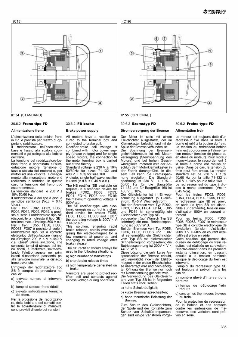
335
30.6.2 Freno tipo FD
Alimentazione freno
L’alimentazione della bobina frenoin c.c. è prevista per mezzo di op-portuno raddrizzatore.Il raddrizzatore nell’esecuzionebase è fissato alla scatola copri-morsetti e già collegato alla bobinadel freno.La tensione del raddrizzatore-bo-bina freno è coordinata all’alim-entazione motore (tensione difase o stellata del motore) e, permotori ad una velocità, il collega-mento alla morsettiera motore èrealizzato in fabbrica. In questocaso la tensione del freno puòessere omessa.La tensione standard è 230 V ±10% 50/60 Hz.Il raddrizzatore è del tipo a diodi asemplice semionda (Vc.c. = 0,45Vc.a.).Per i freni FD02, FD03, FD53,FD04, FD14, FD05, FD15, è previ-sto di serie il raddrizzatore tipo NB(disponibile a richiesta il tipo SB),tensione max. d’impiego 500 V c.a.Per i freni FD55, FD56, FD06,FD06S, FD07 è previsto di serie ilraddrizzatore tipo SB a controlloelettronico dell’eccitazione (tensio-ne d’impiego 200 V < V < 440 Vc.a. Quest’ ultima soluzione, checonsente tempi di sblocco del fre-no ridotti, è realizzata sovraecci-tando l’elettromagnete nei primiistanti d’inserzione passando poialla tensione nominale a distaccofreno avvenuto.
L’impiego del raddrizzatore tipoSB è sempre da prevedere neicasi di:
a) elevato numero di interventiorari
b) tempi di sblocco freno ridotti
c) elevate sollecitazioni termichedel freno.
Per la protezione del raddrizzato-re, della bobina e dei contatti con-tro le sovratensioni di manovra,sono previsti di serie dei varistori.
(C19)(C18)
IP 55 (OPTIONAL )
30.6.2 FD brake
Brake power supply
All motors have a rectifier se-cured to the terminal box andconnected to brake coil.Rectifier-brake coil voltage iscombined with motor power sup-ply (phase voltage) and for singlespeed motors, the connection tothe motor terminal box is carriedout at the factory.Standard voltage is 230 V � 10%50/60Hz for sizes 71-132 and400 V � 10% for size 160.A diode, single half-wave rectifieris used (V.d.c. = 0.45 V.a.c.).
The NB rectifier (SB available onrequest) is a standard device forbrakes FD02, FD03, FD53,FD04, FD14, FD05 and FD15;the maximum operating voltage is500V a.c..The SB rectifier type with elec-tronic energizing control is a stan-dard device for brakes FD55,FD56, FD06, FD06S and FD07;the operating voltage is 200V < V< 440V a.c.This solution, ensuring rapidbrake release, entails over-ener-gizing the electro-magnet for afew moments at power-up, andchanging to rated voltage afterbrake release.
The SB rectifier should always beused in the following situations:
a) high number of starts/stops
b) short brake release times
c) high temperature generated onbrake.
Varistors are used to protect rec-tifier, coil and contacts againstexcess voltage during operation.
30.6.2 Bremstyp FD
Stromversorgung der Bremse
Der Motor ist stets mit einemGleichrichter ausgestattet, der imKlemmkasten befestigt und mit derSpule der Bremse verbunden ist.Die Spannung der Bremsen-gleichrichterspule ist mit Motor-versorgung (Sternspannung desMotors) und bei hohen Gesch-windigkeits motoren wird der An-schluß dem Motorklemmkasten inder Fabrik durchgeführt. In die-sem Fall kann die Bremsspan-nung wegfallen. Die Standard-spannung ist 230 V ± 10% -50/60 Hz für die Baugröße71-132 und für Baugröße 160 ist400 V � 10%.Der Gleichrichter ist in Einweg-schaltung ausgeführt (V Gleich-strom: 0.45 V Wechselstrom).Bei den Bremsen vom Typ FD02,FD03, FD53, FD04, FD14, FD05und FD15 ist serienmäßig einGleichrichter vom Typ NBvorgesehen (auf Wunsch Typ SBlieferbar); die max. Betriebsspan-nung ist 500V W.S.Bei den Bremsen vom Typ FD55,FD56, FD06, FD06S und FD07ist serienmäßig ein Gleichrichtervom Typ SB mit elektronischerSchnellerregung vorgesehen; dieBetriebsspannung ist 200V < V <440V W.S.Diese Lösung, die sehr kurze An-sprechzeiten der Bremse erlaubt,wird verwirklicht, indem der Elektro-magnet in der ersten Einschaltpha-se übererregt wird und nach erfolg-ter Öffnung der Bremse nur nochmit Nennspannung gespeist wird.Die Verwendung des Gleich-rich-ters vom Typ SB ist in folgendenFällen stets vorzusehen:
a) hohe Schalthäufigkeit;
b) kurze Bremsansprechzeiten;
c) hohe thermische Belastung derBremse.
Zum Schutz des Gleichrichters,der Spule und der Kontakte zumSchutz von Schaltüberspannun-gen sind einige Varistoren vorge-
30.6.2 Freins type FD
Alimentation frein
Le moteur est toujours doté d’unredresseur fixé dans la boîte àborne et relié à la bobine du frein.La tension du redresseur-bobinefrein est coordonnée à l’alimenta-tion moteur (tension de phase ouen étoile du moteur). Pour moteurmono-vitesse, le raccordement àla boîte à borne est réalisé enusine. Dans ce cas, la tension dufrein peut être omise. La tensionstandard est de 230 V ± 10%50/60 Hz por la taille 71-132 et400 V � 10% pour la taille 160.Le redresseur est du type à dio-des à mono alternance (Vcc =0.45 Vca).Pour les freins FD02, FD03,FD53, FD04, FD14, FD05, FD15,le redresseur type NB est prévuen série (le type SB est dispo-nible sur demande), tension maxid’utilisation 500V en courant al-ternatif.Pour les freins, FD55, FD56,FD06, FD06S, FD07, le redresseurtype SB à contrôle électronique del’excitation (tension d’utilisation200V < V < 440V en courant alter-natif) est prévu en série.Cette solution, qui permet desdurées de déblocage du frein ré-duites, est réalisée en surexcitantl’électro-aimant dans les premiersinstants d’insertion, en passantensuite à la tension nominalelorsque le déblocage du frein estintervenu.L’emploi du redresseur type SBest toujours à prévoir dans lescas de:
a) nombre élevé d’interventionshoraires
b) temps de déblocage freinréduits
c) contraintes thermiques élevéesdu frein.
Pour la protection du redresseur,de la bobine et des contactscontre les surtensions de ma-noeuvre, des varistors sont pré-vus en série.
IP 54 (STANDARD)
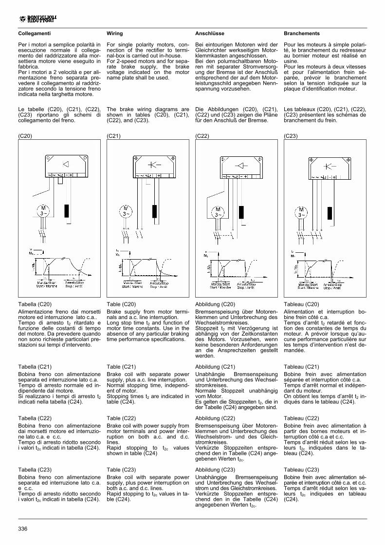
336
(C23)
Wiring
For single polarity motors, con-nection of the rectifier to termi-nal-box is carried out in-house.For 2-speed motors and for sepa-rate brake supply, the brakevoltage indicated on the motorname plate shall be used.
Table (C20)
Brake supply from motor termi-nals and a.c. line interruption.Long stop time t2 and function ofmotor time constants. Use in theabsence of any particular brakingtime performance specifications.
Table (C21)
Brake coil with separate powersupply, plus a.c. line interruption.Normal stopping time, independ-ent of motor.Stopping times t2 are indicated intable (C24).
Table (C22)
Brake coil with power supply frommotor terminals and power inter-ruption on both a.c. and d.c.lines.Rapid stopping to t2c valuesshown in table (C24)
Table (C23)
Brake coil with separate powersupply, plus power interruption onboth a.c. and d.c. lines.Rapid stopping to t2c values in ta-ble (C24).
(C22)(C21)(C20)
The brake wiring diagrams areshown in tables (C20), (C21),(C22), and (C23).
Anschlüsse
Bei eintourigen Motoren wird derGleichrichter werkseitigim Motor-klemmkasten angeschlossen.Bei den polumschaltbaren Moto-ren mit separater Stromversorg-ung der Bremse ist der Anschlußentsprechend der auf dem Motor-leistungsschild angegeben Nenn-spannung vorzusehen.
Branchements
Pour les moteurs à simple polari-té, le branchement du redresseurau bornier moteur est réalisé enusine.Pour les moteurs à deux vitesseset pour l’alimentation frein sé-parée, prévoir le branchementselon la tension indiquée sur laplaque d’identification moteur.
Collegamenti
Per i motori a semplice polarità inesecuzione normale il collega-mento del raddrizzatore alla mor-settiera motore viene eseguito infabbrica.Per i motori a 2 velocità e per ali-mentazione freno separata pre-vedere il collegamento al raddriz-zatore secondo la tensione frenoindicata nella targhetta motore.
Die Abbildungen (C20), (C21),(C22) und (C23) zeigen die Plänefür den Anschluß der Bremse.
Les tableaux (C20), (C21), (C22),(C23) présentent les schémas debranchement du frein.
Le tabelle (C20), (C21), (C22),(C23) riportano gli schemi dicollegamento del freno.
Abbildung (C20)
Bremsenspeisung über Motoren-klemmen und Unterbrechung desWechselstromkreises.Stoppzeit t2 mit Verzögerung istabhängig von der Zeitkonstantendes Motors. Vorzusehen, wennkeine besonderen Anforderungenan die Ansprechzeiten gestelltwerden.
Abbildung (C21)
Unabhängie Bremsenspeisungund Unterbrechung des Wechsel-stromkreises.Normale Stoppzeit unabhängigvom Motor.Es gelten die Stoppzeiten t2, die inder Tabelle (C24) angegeben sind.
Abbildung (C22)
Bremsenspeisung über Motoren-klemmen und Unterbrechung desWechselstrom- und des Gleich-stromkreises.Verkürzte Stoppzeiten entspre-chend den in Tabelle (C24) ange-gebenen Werten t2c.
Abbildung (C23)
Unabhängige Bremsenspeisungund Unterbrechung des Wechsel-strom und des Gleichstromkreises.Verkürzte Stoppzeiten entspre-chend den in die Tabelle (C24)angegebenen Werten t2c.
Tableau (C20)
Alimentation et interruption bo-bine frein côté c.a.Temps d’arrêt t2 retardé et fonc-tion des constantes de temps dumoteur. A prévoir lorsque qu’au-cune performance particulière surles temps d’intervention n’est de-mandée.
Tableau (C21)
Bobine frein avec alimentationséparée et interruption côté c.a.Temps d’arrêt normal et indépen-dant du moteur.On obtient les temps d’arrêt t2 in-diqués dans le tableau (C24).
Tableau (C22)
Bobine frein avec alimentation àpartir des bornes moteurs et in-terruption côté c.a et c.c.Temps d’arrêt réduit selon les va-leurs t2c indiquées dans le ta-bleau (C24).
Tableau (C23)
Bobine frein avec alimentation sé-parée et interruption côté c.a. et c.c.Temps d’arrêt réduit selon les va-leurs t2c indiquées en tableau(C24).
Tabella (C20)
Alimentazione freno dai morsettimotore ed interruzione lato c.a..Tempo di arresto t2 ritardato efunzione delle costanti di tempodel motore. Da prevedere quandonon sono richieste particolari pre-stazioni sui tempi d’intervento.
Tabella (C21)
Bobina freno con alimentazioneseparata ed interruzione lato c.a.Tempo di arresto normale ed in-dipendente dal motore.Si realizzano i tempi di arresto t2indicati nella tabella (C24).
Tabella (C22)
Bobina freno con alimentazionedai morsetti motore ed interruzio-ne lato c.a. e c.c.Tempo di arresto ridotto secondoi valori t2c indicati in tabella (C24).
Tabella (C23)
Bobina freno con alimentazioneseparata ed interruzione lato c.a.e c.c.Tempo di arresto ridotto secondoi valori t2c indicati in tabella (C24).
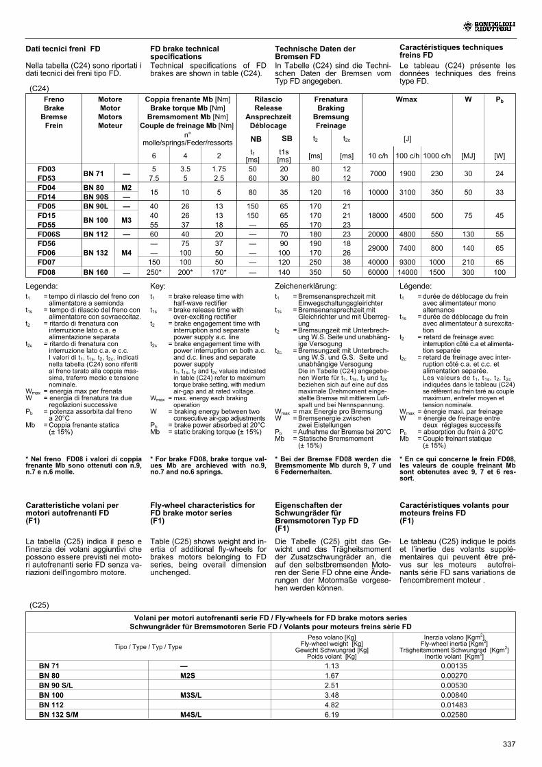
337
Fly-wheel characteristics forFD brake motor series(F1)
(C25)
Volani per motori autofrenanti serie FD / Fly-wheels for FD brake motors seriesSchwungräder für Bremsmotoren Serie FD / Volants pour moteurs freins sèrie FD
Tipo / Type / Typ / Type
Peso volano [Kg]Fly-wheel weight [Kg]
Gewicht Schwungrad [Kg]Poids volant [Kg]
Inerzia volano [Kgm2]Fly-wheel inertia [Kgm2]
Trägheitsmoment Schwungrad [Kgm2]Inertie volant [Kgm2]
BN 71 — 1.13 0.00135
BN 80 M2S 1.67 0.00270
BN 90 S/L 2.51 0.00530
BN 100 M3S/L 3.48 0.00840
BN 112 4.82 0.01483
BN 132 S/M M4S/L 6.19 0.02580
Key:
Technische Daten derBremsen FDIn Tabelle (C24) sind die Techni-schen Daten der Bremsen vomTyp FD angegeben.
(C24)
FD brake technicalspecificationsTechnical specifications of FDbrakes are shown in table (C24).
Caractéristiques techniquesfreins FDLe tableau (C24) présente lesdonnées techniques des freinstype FD.
Dati tecnici freni FD
Nella tabella (C24) sono riportati idati tecnici dei freni tipo FD.
Eigenschaften derSchwungräder fürBremsmotoren Typ FD(F1)
Zeichenerklärung:
Table (C25) shows weight and in-ertia of additional fly-wheels forbrakes motors belonging to FDseries, being overail dimensionunchenged.
Caractéristiques volants pourmoteurs freins FD(F1)
Légende:
Le tableau (C25) indique le poidset l’inertie des volants supplé-mentaires qui peuvent être pré-vus sur les moteurs autofrei-nants série FD sans variations del'encombrement moteur .
Caratteristiche volani permotori autofrenanti FD(F1)
Legenda:
La tabella (C25) indica il peso el’inerzia dei volani aggiuntivi chepossono essere previsti nei moto-ri autofrenanti serie FD senza va-riazioni dell'ingombro motore.
Die Tabelle (C25) gibt das Ge-wicht und das Trägheitsmomentder Zusatzschwungräder an, dieauf den selbstbremsenden Moto-ren der Serie FD ohne eine Ände-rungen der Motormaße vorgese-hen werden können.
t1 = Bremsenansprechzeit mitEinwegschaltungsgleirichter
t1s = Bremsenansprechzeit mitGleichrichter und mit Überreg-ung
t2 = Bremsungzeit mit Unterbrech-ung W.S. Seite und unabhäng-ige Versogung
t2c = Bremsungzeit mit Unterbrech-ung W.S. und G.S. Seite undunabhängige VersogungDie in Tabelle (C24) angegebe-nen Werte für t1, t1s, t2 und t2cbeziehen sich auf eine auf dasmaximale Drehmoment einge-stellte Bremse mit mittlerem Luft-spalt und bei Nennspannung.
Wmax = max Energie pro BremsungW =Bremsenergie zwischen
zwei EistellungenPb =Aufnahme der Bremse bei 20°CMb = Statische Bremsmoment
(± 15%)
t1 = durée de déblocage du freinavec alimentateur monoalternance
t1s = durée de déblocage du freinavec alimentateur à surexcita-tion
t2 = retard de freinage avecinterruption côté c.a et alimenta-tion separée
t2c = retard de freinage avec inter-ruption côté c.a. et c.c. etalimentation separée.Les valeurs de t1, t1s, t2, t2cindiquées dans le tableau (C24)se réfèrent au frein taré au couplemaximum, entrefer moyen ettension nominale.
Wmax = énergie maxi. par freinageW = énergie de freinage entre
deux réglages successifsPb = absorption du frein à 20°CMb =Couple freinant statique
(± 15%)
t1 = brake release time withhalf-wave rectifier
t1s = brake release time withover-exciting rectifier
t2 = brake engagement time withinterruption and separatepower supply a.c. line
t2c = brake engagement time withpower interruption on both a.c.and d.c. lines and separatepower supplyt1, t1s, t2 and t2c values indicatedin table (C24) refer to maximumtorque brake setting, with mediumair-gap and at rated voltage.
Wmax = max. energy each brakingoperation
W = braking energy between twoconsecutive air-gap adjustments
Pb = brake power absorbed at 20°CMb = static braking torque (± 15%)
t1 = tempo di rilascio del freno conalimentatore a semionda
t1s = tempo di rilascio del freno conalimentatore con sovraeccitaz.
t2 = ritardo di frenatura coninterruzione lato c.a. ealimentazione separata
t2c = ritardo di frenatura coninterruzione lato c.a. e c.c.I valori di t1, t1s, t2, t2c, indicatinella tabella (C24) sono riferitial freno tarato alla coppia mas-sima, traferro medio e tensionenominale.
Wmax = energia max per frenataW = energia di frenatura tra due
regolazioni successivePb = potenza assorbita dal freno
a 20°CMb =Coppia frenante statica
(± 15%)
FrenoBrakeBremseFrein
MotoreMotorMotorsMoteur
Coppia frenante Mb [Nm]Brake torque Mb [Nm]Bremsmoment Mb [Nm]
Couple de freinage Mb [Nm]
RilascioRelease
AnsprechzeitDéblocage
FrenaturaBraking
BremsungFreinage
Wmax W Pb
n°molle/springs/Feder/ressorts
t2 t2c [J]
6 4 2 t1[ms]
t1s[ms] [ms] [ms] 10 c/h 100 c/h 1000 c/h [MJ] [W]
FD03BN 71 —
5 3.5 1.75 50 20 80 127000 1900 230 30 24
FD53 7.5 5 2.5 60 30 80 12FD04 BN 80 M2
15 10 5 80 35 120 16 10000 3100 350 50 33FD14 BN 90S —FD05 BN 90L — 40 26 13 150 65 170 21
18000 4500 500 75 45FD15BN 100 M3
40 26 13 150 65 170 21FD55 55 37 18 — 65 170 23FD06S BN 112 — 60 40 20 — 70 180 23 20000 4800 550 130 55FD56
BN 132 M4— 75 37 — 90 190 18
29000 7400 800 140 65FD06 — 100 50 — 100 170 26FD07 150 100 50 — 120 250 38 40000 9300 1000 210 65
FD08 BN 160 — 250* 200* 170* — 140 350 50 60000 14000 1500 300 100
* For brake FD08, brake torque val-ues Mb are archieved with no.9,no.7 and no.6 springs.
* Bei der Bremse FD08 werden dieBremsmomente Mb durch 9, 7 und6 Federnerhalten.
* En ce qui concerne le frein FD08,les valeurs de couple freinant Mbsont obtenutes avec 9, 7 et 6 res-sort.
* Nel freno FD08 i valori di coppiafrenante Mb sono ottenuti con n.9,n.7 e n.6 molle.
NB SB
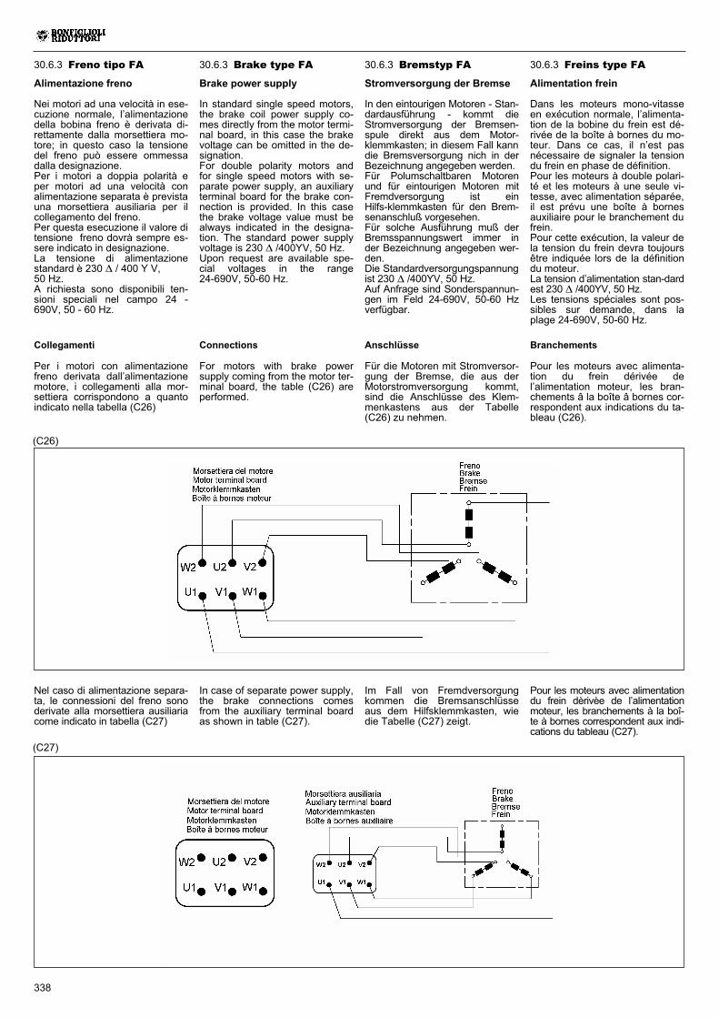
338
Nel caso di alimentazione separa-ta, le connessioni del freno sonoderivate alla morsettiera ausiliariacome indicato in tabella (C27)
(C27)
30.6.3 Brake type FA
Brake power supply
In standard single speed motors,the brake coil power supply co-mes directly from the motor termi-nal board, in this case the brakevoltage can be omitted in the de-signation.For double polarity motors andfor single speed motors with se-parate power supply, an auxiliaryterminal board for the brake con-nection is provided. In this casethe brake voltage value must bealways indicated in the designa-tion. The standard power supplyvoltage is 230 � /400YV, 50 Hz.Upon request are available spe-cial voltages in the range24-690V, 50-60 Hz.
30.6.3 Bremstyp FA
Stromversorgung der Bremse
In den eintourigen Motoren - Stan-dardausführung - kommt dieStromversorgung der Bremsen-spule direkt aus dem Motor-klemmkasten; in diesem Fall kanndie Bremsversorgung nich in derBezeichnung angegeben werden.Für Polumschaltbaren Motorenund für eintourigen Motoren mitFremdversorgung ist einHilfs-klemmkasten für den Brem-senanschluß vorgesehen.Für solche Ausführung muß derBremsspannungswert immer inder Bezeichnung angegeben wer-den.Die Standardversorgungspannungist 230 � /400YV, 50 Hz.Auf Anfrage sind Sonderspannun-gen im Feld 24-690V, 50-60 Hzverfügbar.
30.6.3 Freins type FA
Alimentation frein
Dans les moteurs mono-vitasseen exécution normale, l’alimenta-tion de la bobine du frein est dé-rivée de la boîte à bornes du mo-teur. Dans ce cas, il n’est pasnécessaire de signaler la tensiondu frein en phase de définition.Pour les moteurs à double polari-té et les moteurs à une seule vi-tesse, avec alimentation séparée,il est prévu une boîte à bornesauxiliaire pour le branchement dufrein.Pour cette exécution, la valeur dela tension du frein devra toujoursêtre indiquée lors de la définitiondu moteur.La tension d’alimentation stan-dardest 230 � /400YV, 50 Hz.Les tensions spéciales sont pos-sibles sur demande, dans laplage 24-690V, 50-60 Hz.
30.6.3 Freno tipo FA
Alimentazione freno
Nei motori ad una velocità in ese-cuzione normale, l’alimentazionedella bobina freno è derivata di-rettamente dalla morsettiera mo-tore; in questo caso la tensionedel freno può essere ommessadalla designazione.Per i motori a doppia polarità eper motori ad una velocità conalimentazione separata è previstauna morsettiera ausiliaria per ilcollegamento del freno.Per questa esecuzione il valore ditensione freno dovrà sempre es-sere indicato in designazione.La tensione di alimentazionestandard è 230 � / 400 Y V,50 Hz.A richiesta sono disponibili ten-sioni speciali nel campo 24 -690V, 50 - 60 Hz.
Connections
For motors with brake powersupply coming from the motor ter-minal board, the table (C26) areperformed.
(C26)
Anschlüsse
Für die Motoren mit Stromversor-gung der Bremse, die aus derMotorstromversorgung kommt,sind die Anschlüsse des Klem-menkastens aus der Tabelle(C26) zu nehmen.
Branchements
Pour les moteurs avec alimenta-tion du frein dérivée del’alimentation moteur, les bran-chements â la boîte â bornes cor-respondent aux indications du ta-bleau (C26).
Collegamenti
Per i motori con alimentazionefreno derivata dall’alimentazionemotore, i collegamenti alla mor-settiera corrispondono a quantoindicato nella tabella (C26)
Im Fall von Fremdversorgungkommen die Bremsanschlüsseaus dem Hilfsklemmkasten, wiedie Tabelle (C27) zeigt.
Pour les moteurs avec alimentationdu frein dèrivèe de l’alimentationmoteur, les branchements à la boî-te à bornes correspondent aux indi-cations du tableau (C27).
In case of separate power supply,the brake connections comesfrom the auxiliary terminal boardas shown in table (C27).
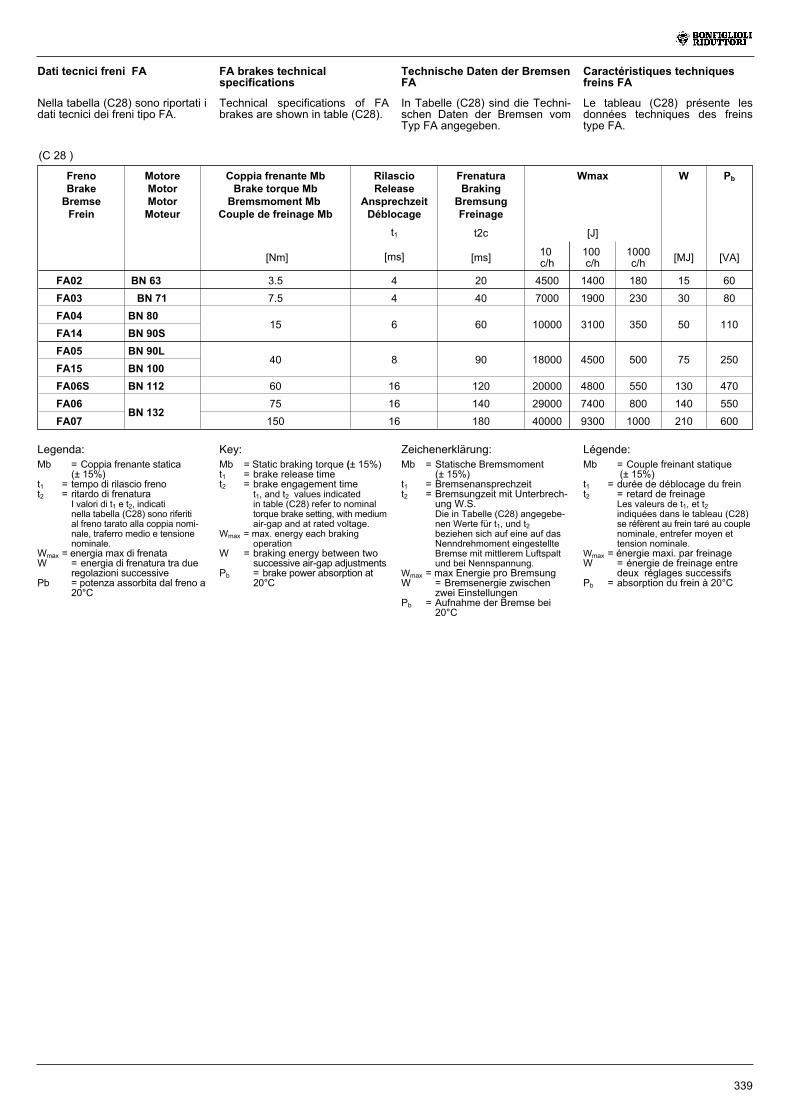
339
FrenoBrakeBremseFrein
MotoreMotorMotorMoteur
Coppia frenante MbBrake torque MbBremsmoment Mb
Couple de freinage Mb
RilascioRelease
AnsprechzeitDéblocage
FrenaturaBraking
BremsungFreinage
Wmax W Pb
t1 t2c [J]
[Nm] [ms] [ms] 10c/h
100c/h
1000c/h [MJ] [VA]
FA02 BN 63 3.5 4 20 4500 1400 180 15 60
FA03 BN 71 7.5 4 40 7000 1900 230 30 80
FA04 BN 8015 6 60 10000 3100 350 50 110
FA14 BN 90S
FA05 BN 90L40 8 90 18000 4500 500 75 250
FA15 BN 100
FA06S BN 112 60 16 120 20000 4800 550 130 470
FA06BN 132
75 16 140 29000 7400 800 140 550
FA07 150 16 180 40000 9300 1000 210 600
Key:
Technische Daten der BremsenFA
In Tabelle (C28) sind die Techni-schen Daten der Bremsen vomTyp FA angegeben.
FA brakes technicalspecifications
Technical specifications of FAbrakes are shown in table (C28).
Caractéristiques techniquesfreins FA
Le tableau (C28) présente lesdonnées techniques des freinstype FA.
Dati tecnici freni FA
Nella tabella (C28) sono riportati idati tecnici dei freni tipo FA.
Zeichenerklärung: Légende:Legenda:
(C 28 )
Mb = Statische Bremsmoment(± 15%)
t1 = Bremsenansprechzeitt2 = Bremsungzeit mit Unterbrech-
ung W.S.Die in Tabelle (C28) angegebe-nen Werte für t1, und t2beziehen sich auf eine auf dasNenndrehmoment eingestellteBremse mit mittlerem Luftspaltund bei Nennspannung.
Wmax = max Energie pro BremsungW = Bremsenergie zwischen
zwei EinstellungenPb = Aufnahme der Bremse bei
20°C
Mb = Couple freinant statique(± 15%)
t1 = durée de déblocage du freint2 = retard de freinage
Les valeurs de t1, et t2indiquées dans le tableau (C28)se réfèrent au frein taré au couplenominale, entrefer moyen ettension nominale.
Wmax = énergie maxi. par freinageW = énergie de freinage entre
deux réglages successifsPb = absorption du frein à 20°C
Mb = Static braking torque (± 15%)t1 = brake release timet2 = brake engagement time
t1, and t2 values indicatedin table (C28) refer to nominaltorque brake setting, with mediumair-gap and at rated voltage.
Wmax = max. energy each brakingoperation
W = braking energy between twosuccessive air-gap adjustments
Pb = brake power absorption at20°C
Mb = Coppia frenante statica(± 15%)
t1 = tempo di rilascio frenot2 = ritardo di frenatura
I valori di t1 e t2, indicatinella tabella (C28) sono riferitial freno tarato alla coppia nomi-nale, traferro medio e tensionenominale.
Wmax = energia max di frenataW = energia di frenatura tra due
regolazioni successivePb = potenza assorbita dal freno a
20°C
340
30.7.0 SPECIALEXECUTIONS
30.7.1 Thermal protectivedevices
In addition to the standard protec-tion provided by the magneto-ther-mal cut-out device, motors can besupplied with built-in thermalprobes to protect windings againstoverheating caused, for example,by inadequate ventilation or by anintermittent duty.This additional protection shouldalways be specified for servo-ven-tilated motors (IC416).
Thermistors(E3, E6)
These are semi-conductors hav-ing rapid resistance variationwhen they are close to the ratedintervention temperature.Variations of the R = f(T) charac-teristic are specified under DIN44081, IEC 34-11 Standards.
These elements have several ad-vantages: compact dimensions,rapid response time and,beingcontact-free, absolutely no wear.Positive temperature coefficientthermistors are normally used(also known as PTC “cold con-ductor resistors”).
Contrary to bimetallic thermostates,they cannot directly intervene oncurrents of energizing coils, andmust therefore be connected to aspecial control unit (triggering appa-ratus) to be interfaced with the ex-ternal connections.Thus protected, three PTCs con-nected in series are installed inthe winding, the terminals ofwhich are located on the auxiliaryterminal-board.
Bimetallic thermostates(D3)
These types of protective de-vices contain a bimetal disk in-side a housing. When the ratedtemperature is reached, the diskswitches the contacts from theirinitial rest position.As temperature falls, the diskand contacts automatically returnto rest position.Three bimetallic thermostatesconnected in series are usuallyemployed, with normally closedcontacts. The terminals are lo-cated on an auxiliaryterminalboard.
30.7.0 SONDERAUSFÜHRUN-GEN
30.7.1 ThermischeSchutzeinrichtungen
Abgesehen von den Motor-schutzschaltern mit thermischemund elektromagnetischem Aus-löser können die Motoren mit inte-grierten Temperaturfühlern zumSchutz der Wicklung vor Überhit-zung z.B. wegen unzureichenderLüftung oder Aussetzbetriebsausgestattet werden.Diese Schutzeinrichtung muß beifremdbelüfteten Motoren stetsvorgesehen werden (IC416).
Temperaturfühler undThermistoren(E3, E6)
Hierbei handelt es sich um Halblei-ter, die eine schnelle Änderung desWiderstands in der Nähe der Nenn-ansprechtemperatur zeigen.Der Verlauf der Kennlinie R = f(T)ist durch die DIN-Normen 44081und IEC 34-11 festgelegt.
Diese Sensoren haben folgendeVorteile: sie weisen geringe Au-ßenmaße und eine äußerst kurzeAnsprechzeit auf und sind voll-kommen verschleißfrei, da sieberührungslos arbeiten.
Im allgemeinen werden Thermis-toren mit positivem Temperatur-koeffizienten verwendet, die auchals “Kaltleiter” (PTC-Widerstän-de) bezeichnet werden.Im Unterschied zu Bimetall-Tem-peraturfühlern können sie nichtdirekt auf die Erregungsströmeder Spulen wirken, sondern müs-sen an eine spezielle Steuerein-heit (Auslösegerät) angeschlos-sen werden, die mit den externenAnschlüssen kompatibel ist.Mit dieser Schutzeinrichtung wer-den drei in Reihe geschaltetePTC-Widerstände in die Wicklungeingesetzt, deren Endanschlüssean einer Zusatzklemmleiste ver-fügbar sind.
Bimetall-Temperaturfühler(D3)
Diese Schutzeinrichtungen beste-hen aus einer Kapsel, in der sicheine Bimetallscheibe befindet, diebei Erreichen der Nennan-sprechtemperatur anspricht.Nach Absenkung der Temperaturgeht der Schaltkontakt auto-matisch in Ruhestellung zurück.Normalerweise werden drei inReihe geschaltete Bimetallfühlermit Öffnern verwendet, derenEndverschlüsse an einer Zu-satzklemmleiste verfügbar sind.
30.7.0 EXECUTIONSSPECIALES
30.7.1 Protectionsthermiques
Outre la protection garantie parl’interrupteur magnétothermique,les moteurs peuvent être équipésde sondes thermiques incorpo-rées pour protéger le bobinagecontre une surchauffe excessivedue par exemple à une ventila-tion insuffisante ou un service in-termittent.Cette protection devrait toujoursêtre prévue pour les moteurs ser-voventilés (IC416).
Sondes thermométriques(E3, E6)
Ce sont des semiconducteurs quiprésentent une variation rapide derésistance à proximité de la tem-pérature nominale d’intervention.L’évolution de la caractéristiqueR = f(T) est défini par les NormesDIN 44081, IEC 34-11.
Ces capteurs présentent l’avan-tage d’avoir des encombrementsréduits, un temps de réponse trèsbref et, du fait que le fonctionne-ment a lieu sans contact, il sontexempts d’usure.
En général, on utilise des ther-mistors à coefficient de tempéra-ture positif dénommés également“résistors à conducteur froid”PTC.Contrairement aux sondes ther-miques bimétalliques, ils ne peu-vent intervenir directement surles courants des bobines d’exci-tation et doivent par conséquentêtre reliés à une unité spéciale decontrôle (appareil de déconnec-tion) à interfacer aux connexionsextérieures.Avec cette protection, trois son-des, reliées en série, sont insé-rées dans le bobinage avec ex-trémités disponibles dans lebornier auxiliaire.
Sondes thermiquesbimétalliques(D3)
Les protecteurs de ce typecontiennent, dans une enveloppeinterne, un disque bimétalliquequi, lorsque la température nomi-nale d’intervention est atteinte,commute les contacts de la posi-tion de repos.Avec la diminution de la tempéra-ture, le disque et les contacts re-prennent automatiquement laposition de repos.Normalement, on utilise trois son-des bimétalliques en série aveccontacts normalement fermés etextrémités disponibles dans unbornier auxiliaire.
30.7.0 ESECUZIONISPECIALI
30.7.1 Protezioni termiche
Oltre alla protezione garantitadall’interruttore magnetotermico, imotori possono essere provvisti disonde termiche incorporate perproteggere l’avvolgimento da ec-cessivo riscaldamento dovuto(p.es.) a scarsa ventilazione o ser-vizio intermittente.Questa protezione dovrebbe sem-pre essere prevista per motori ser-voventilati (IC416).
Sonde termiche a termistori(E3, E6)
Sono dei semiconduttori che pre-sentano una rapida variazione diresistenza in prossimità della tem-peratura nominale di intervento.L’andamento della caratteristicaR= f (T) è normalizzato dalle Nor-me DIN 44081, IEC 34-11.
Questi sensori presentano il van-taggio di avere ingombri ridotti,un tempo di risposta molto conte-nuto e, dato che il funzionamentoavviene senza contatti, sonocompletamente esenti da usura.In genere vengono impiegati ter-mistori a coefficiente di tempera-tura positivo denominati anche“resistori a conduttore freddo”PTC.
A differenza delle sonde termichebimetalliche, non possono interve-nire direttamente sulle correntidelle bobine di eccitazione e de-vono pertanto essere collegati aduna speciale unità di controllo (ap-parecchio di sgancio) da interfac-ciare alle connessioni esterne.Con questa protezione vengonoinseriti tre PTC, collegati in serie,nell’avvolgimento con terminali di-sponibili in morsettiera ausiliaria.
Sonde termiche bimetalliche(D3)
I protettori di questo tipo conten-gono all’interno di un involucro undisco bimetallico che, raggiuntala temperatura nominale di inter-vento, commuta i contatti dallaposizione di riposo.Con la diminuzione della tempe-ratura, il disco e i contatti ripren-dono automaticamente la posizio-ne di riposo.Normalmente si impiegano tresonde bimetalliche in serie concontatti normalmente chiusi e ter-minali disponibili in una morset-tiera ausiliaria.
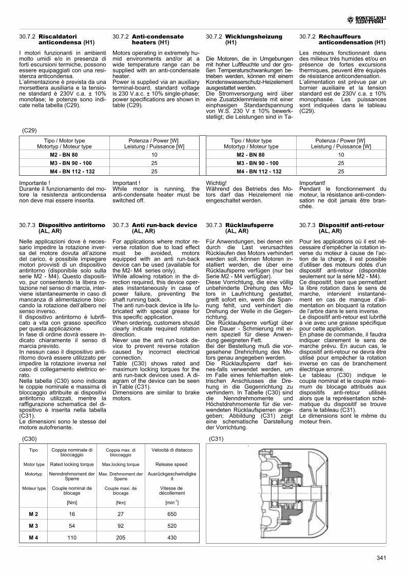
341
Important !While motor is running, theanti-condensate heater must beswitched off.
30.7.2 Anti-condensateheaters (H1)
Motors operating in extremely hu-mid environments and/or at awide temperature range can besupplied with an anti-condensateheater.Power is supplied via an auxiliaryterminal-board, standard voltageis 230 V.a.c. ± 10% single-phase;power specifications are shown intable (C29).
Wichtig!Während des Betriebs des Mo-tors darf das Heizelement nieeingeschaltet werden.
30.7.2 Wicklungsheizung(H1)
Die Motoren, die in Umgebungenmit hoher Luftfeuchte und der gro-ßen Temperaturschwankungen be-trieben werden, können mit einemKondenswasserschutz-Heizelementausgestattet werden.Die Stromversorgung wird übereine Zusatzklemmleiste mit einereinphasigen Standardspannungvon W.S. 230 V ± 10% bewerk-stelligt; die Leistungen sind in Ta-
Important!Pendant le fonctionnement dumoteur, la résistance anti-conden-sation ne doit jamais être bran-chée.
30.7.2 Réchauffeursanticondensation (H1)
Les moteurs fonctionnant dansdes milieux très humides et/ou enprésence de fortes excursionsthermiques, peuvent être équipésde résistance anticondensation.L’alimentation est prévue par unbornier auxiliaire et la tensionstandard est de 230V c.a. ± 10%monophasée. Les puissancessont indiquées dans le tableau(C29).
Importante !Durante il funzionamento del mo-tore la resistenza anticondensanon deve mai essere inserita.
30.7.2 Riscaldatorianticondensa (H1)
I motori funzionanti in ambientimolto umidi e/o in presenza diforti escursioni termiche, possonoessere equipaggiati con una resi-stenza anticondensa.L’alimentazione è prevista da unamorsettiera ausiliaria e la tensio-ne standard è 230V c.a. ± 10%monofase; le potenze sono indi-cate nella tabella (C29).
(C29)
Tipo / Motor typeMotortyp / Moteur type
Potenza / Power [W]Leistung / Puissance [W]
M2 - BN 80 10
M3 - BN 90 - 100 25
M4 - BN 112 - 132 25
(C31)(C30)
Tipo
Motor type
Motortyp
Moteur type
Coppia nominale dibloccaggio
Rated locking torque
Nenndrehmoment derSperre
Couple nominal deblocage
[Nm]
Coppia max. dibloccaggio
Max.locking torque
Max. Drehmoment derSperre
Couple maxi. deblocage
[Nm]
Velocità di distacco
Release speed
Ausrückgeschwindigkeit
Vitesse dedécollement
[min-1]
M 2 16 27 650
M 3 54 92 520
M 4 110 205 430
30.7.3 Anti run-back device(AL, AR)
For applications where motor re-verse rotation due to load effectmust be avoided, motorsequipped with an anti run-backdevice can be used (available forthe M2- M4 series only).While allowing rotation in the di-rection required, this device oper-ates instantaneously in case ofpower failure, preventing theshaft running back.The anti run-back device is life lu-bricated with special grease forthis specific application.When ordering, customers shouldclearly indicate required rotationdirection.Never use the anti run-back de-vice to prevent reverse rotationcaused by incorrect electricalconnection.Table (C30) shows rated andmaximum locking torques for theanti run-back devices used. A di-agram of the device can be seenin Table (C31).Dimensions are similar to brakemotors.
30.7.3 Rücklaufsperre(AL, AR)
Für Anwendungen, bei denen eindurch die Last verursachtesRücklaufen des Motors verhindertwerden soll, können Motoren in-stalliert werden, die über eineRücklaufsperre verfügen (nur beiSerie M2 - M4 verfügbar).Diese Vorrichtung, die eine völligunbehinderte Drehung des Mo-tors in Laufrichtung gestattet,greift sofort ein, wenn die Span-nung fehlt, und verhindert dieDrehung der Welle in die Gegen-richtung.Die Rücklaufsperre verfügt übereine Dauer - Schmierung mit ei-nem speziell für diese Anwen-dung geeigneten Fett.Bei der Bestellung muß die vor-gesehene Drehrichtung des Mo-tors genau angegeben werden.Die Rücklaufsperre darf kei-nes-falls verwendet werden, umim Falle eines fehlerhaften elek-trischen Anschlusses die Dre-hung in die Gegenrichtung zuverhindern. In Tabelle (C30) sinddie Nenndrehmomente undHöchstdrehmomente für die ver-wendeten Rücklaufsperren ange-geben; Abbildung (C31) zeigteine schematische Darstellungder Vorrichtung.
30.7.3 Dispositif anti-retour(AL, AR)
Pour les applications où il est né-cessaire d’empêcher la rotation in-verse du moteur à cause de l’ac-tion de la charge, il est possibled’utiliser des moteurs dotés d’undispositif anti-retour (disponibleseulement sur la série M2 - M4).Ce dispositif, bien que permettantla libre rotation dans le sens demarche, intervient instantané-ment en cas de manque d’ali-mentation en bloquant la rotationde l’arbre dans le sens inverse.Le dispositif anti-retour est lubrifiéà vie avec une graisse spécifiquepour cette application.En phase de commande, il faudraindiquer clairement le sens demarche prévu. En aucun cas, ledispositif anti-retour ne devra êtreutilisé pour empêcher la rotationinverse en cas de branchementélectrique erroné.Le tableau (C30) indique lecouple nominal et le couple maxi-mum de blocage attribués auxdispositifs anti-retour utilisésalors que la représentation sché-matique du dispositif se trouvedans le tableau (C31).Le dimensions sont le même dumoteur frein.
30.7.3 Dispositivo antiritorno(AL, AR)
Nelle applicazioni dove è neces-sario impedire la rotazione inver-sa del motore dovuta all’azionedel carico, è possibile impiegaremotori provvisti di un dispositivoantiritorno (disponibile solo sullaserie M2 - M4). Questo dispositi-vo, pur consentendo la libera ro-tazione nel senso di marcia, inter-viene istantaneamente in caso dimancanza di alimentazione bloc-cando la rotazione dell’albero nelsenso inverso.Il dispositivo antiritorno è lubrifi-cato a vita con grasso specificoper questa applicazione.In fase di ordine dovrà essere in-dicato chiaramente il senso dimarcia previsto.In nessun caso il dispositivo anti-ritorno dovrà essere utilizzato perimpedire la rotazione inversa nelcaso di collegamento elettrico er-rato.Nella tabella (C30) sono indicatele coppie nominale e massima dibloccaggio attribuite ai dispositiviantiritorno utilizzati, mentre laraffigurazione schematica del di-spositivo è inserita nella tabella(C31).Le dimensioni sono le stesse delmotore autofrenante.
Tipo / Motor typeMotortyp / Moteur type
Potenza / Power [W]Leistung / Puissance [W]
M2 - BN 80 10
M3 - BN 90 - 100 25
M4 - BN 112 - 132 25
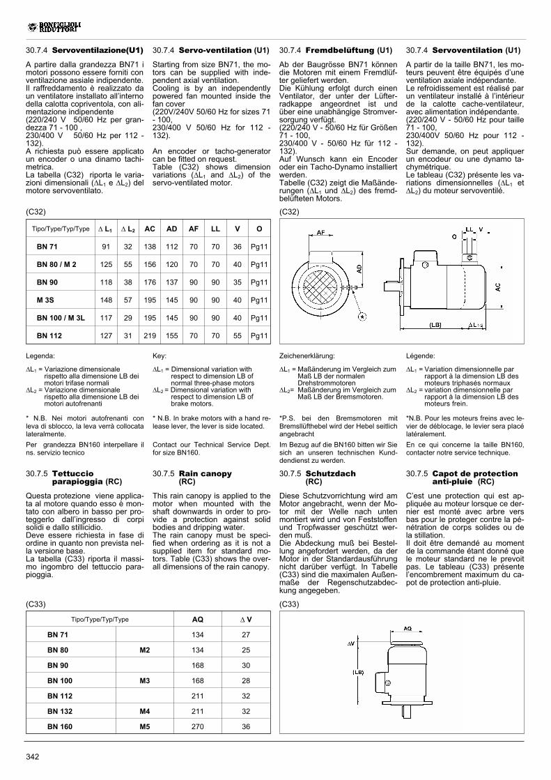
342
30.7.5 Rain canopy(RC)
This rain canopy is applied to themotor when mounted with theshaft downwards in order to pro-vide a protection against solidbodies and dripping water.The rain canopy must be speci-fied when ordering as it is not asupplied item for standard mo-tors. Table (C33) shows the over-all dimensions of the rain canopy.
Tipo/Type/Typ/Type AQ V
BN 71 134 27
BN 80 M2 134 25
BN 90 168 30
BN 100 M3 168 28
BN 112 211 32
BN 132 M4 211 32
BN 160 M5 270 36
30.7.5 Schutzdach(RC)
Diese Schutzvorrichtung wird amMotor angebracht, wenn der Mo-tor mit der Welle nach untenmontiert wird und von Feststoffenund Tropfwasser geschützt wer-den muß.Die Abdeckung muß bei Bestel-lung angefordert werden, da derMotor in der Standardausführungnicht darüber verfügt. In Tabelle(C33) sind die maximalen Außen-maße der Regenschutzabdec-kung angegeben.
30.7.5 Capot de protectionanti-pluie (RC)
C’est une protection qui est ap-pliquée au moteur lorsque ce der-nier est monté avec arbre versbas pour le proteger contre la pé-nétration de corps solides ou dela stillation.Il doit être demandé au momentde la commande étant donné quele moteur standard ne le prevoitpas. Le tableau (C33) présentel’encombrement maximum du ca-pot de protection anti-pluie.
30.7.5 Tettuccioparapioggia (RC)
Questa protezione viene applica-ta al motore quando esso è mon-tato con albero in basso per pro-teggerlo dall’ingresso di corpisolidi e dallo stillicidio.Deve essere richiesta in fase diordine in quanto non prevista nel-la versione base.La tabella (C33) riporta il massi-mo ingombro del tettuccio para-pioggia.
(C33)(C33)
Tipo/Type/Typ/Type L1 L2 AC AD AF LL V O
BN 71 91 32 138 112 70 70 36 Pg11
BN 80 / M 2 125 55 156 120 70 70 40 Pg11
BN 90 118 38 176 137 90 90 35 Pg11
M 3S 148 57 195 145 90 90 40 Pg11
BN 100 / M 3L 117 29 195 145 90 90 40 Pg11
BN 112 127 31 219 155 70 70 55 Pg11
Key:
L1 = Dimensional variation withrespect to dimension LB ofnormal three-phase motors
L2 = Dimensional variation withrespect to dimension LB ofbrake motors.
* N.B. In brake motors with a hand re-lease lever, the lever is side located.
Contact our Technical Service Dept.for size BN160.
30.7.4 Servo-ventilation (U1)
Starting from size BN71, the mo-tors can be supplied with inde-pendent axial ventilation.Cooling is by an independentlypowered fan mounted inside thefan cover(220V/240V 50/60 Hz for sizes 71- 100,230/400 V 50/60 Hz for 112 -132).
An encoder or tacho-generatorcan be fitted on request.Table (C32) shows dimensionvariations (L1 and L2) of theservo-ventilated motor.
(C32)
Zeichenerklärung:
L1 = Maßänderung im Vergleich zumMaß LB der normalenDrehstrommotoren
L2= Maßänderung im Vergleich zumMaß LB der Bremsmotoren.
*P.S. bei den Bremsmotoren mitBremsllüfthebel wird der Hebel seitlichangebracht
Im Bezug auf die BN160 bitten wir Siesich an unseren technischen Kund-dendienst zu werden.
Légende:
L1 = Variation dimensionnelle parrapport à la dimension LB desmoteurs triphasés normaux
L2 = variation dimensionnelle parrapport à la dimension LB desmoteurs frein.
*N.B. Pour les moteurs freins avec le-vier de déblocage, le levier sera placélatéralement.
En ce qui concerne la taille BN160,contacter notre service technique.
Legenda:
L1 = Variazione dimensionalerispetto alla dimensione LB deimotori trifase normali
L2 = Variazione dimensionalerispetto alla dimensione LB deimotori autofrenanti
* N.B. Nei motori autofrenanti conleva di sblocco, la leva verrà collocatalateralmente.
Per grandezza BN160 interpellare ilns. servizio tecnico
30.7.4 Fremdbelüftung (U1)
Ab der Baugrösse BN71 könnendie Motoren mit einem Fremdlüf-ter geliefert werden.Die Kühlung erfolgt durch einenVentilator, der unter der Lüfter-radkappe angeordnet ist undüber eine unabhängige Stromver-sorgung verfügt.(220/240 V - 50/60 Hz für Größen71 - 100,230/400 V - 50/60 Hz für 112 -132).Auf Wunsch kann ein Encoderoder ein Tacho-Dynamo installiertwerden.Tabelle (C32) zeigt die Maßände-rungen (L1 und L2) des fremd-belüfteten Motors.
30.7.4 Servoventilation (U1)
A partir de la taille BN71, les mo-teurs peuvent être équipés d’uneventilation axiale indépendante.Le refroidissement est réalisé parun ventilateur installé à l’intérieurde la calotte cache-ventilateur,avec alimentation indépendante.(220/240 V - 50/60 Hz pour taille71 - 100,230/400V 50/60 Hz pour 112 -132).Sur demande, on peut appliquerun encodeur ou une dynamo ta-chymétrique.Le tableau (C32) présente les va-riations dimensionnelles (L1 etL2) du moteur servoventilé.
30.7.4 Servoventilazione(U1)
A partire dalla grandezza BN71 imotori possono essere forniti conventilazione assiale indipendente.Il raffreddamento è realizzato daun ventilatore installato all’internodella calotta copriventola, con ali-mentazione indipendente(220/240 V 50/60 Hz per gran-dezza 71 - 100 ,230/400 V 50/60 Hz per 112 -132).A richiesta può essere applicatoun encoder o una dinamo tachi-metrica.La tabella (C32) riporta le varia-zioni dimensionali (L1 e L2) delmotore servoventilato.
(C32)
343
30.8.0 TABELLE DEI DATI TECNICI DEI MOTORIMOTOR SELECTION CHARTSMOTORENAUSWAHL TABELLENTABLEAUX CARACTERISTIQUES TECHNIQUES DES MOTEURS
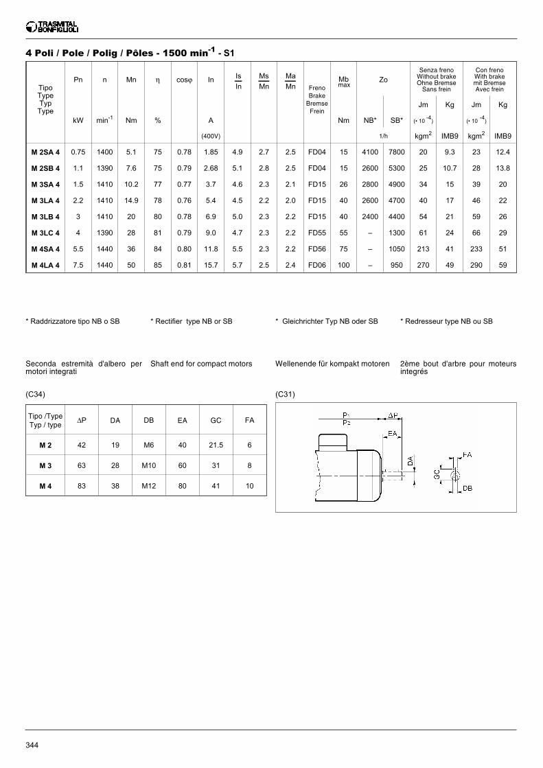
4 Poli / Pole / Polig / Pôles - 1500 min-1 - S1
* Rectifier type NB or SB
TipoTypeTypType
Pn n Mn η cosϕ In Is
In
Ms
Mn
Ma
Mn FrenoBrakeBremseFrein
Mb Zo
Senza frenoWithout brakeOhne BremseSans frein
Con frenoWith brakemit BremseAvec frein
Jm Kg Jm Kg
kW min-1 Nm % A Nm NB* SB* (• 10-4) (• 10
-4)
(400V) 1/h kgm2 IMB9 kgm2 IMB9
M 2SA 4 0.75 1400 5.1 75 0.78 1.85 4.9 2.7 2.5 FD04 15 4100 7800 20 9.3 23 12.4
M 2SB 4 1.1 1390 7.6 75 0.79 2.68 5.1 2.8 2.5 FD04 15 2600 5300 25 10.7 28 13.8
M 3SA 4 1.5 1410 10.2 77 0.77 3.7 4.6 2.3 2.1 FD15 26 2800 4900 34 15 39 20
M 3LA 4 2.2 1410 14.9 78 0.76 5.4 4.5 2.2 2.0 FD15 40 2600 4700 40 17 46 22
M 3LB 4 3 1410 20 80 0.78 6.9 5.0 2.3 2.2 FD15 40 2400 4400 54 21 59 26
M 3LC 4 4 1390 28 81 0.79 9.0 4.7 2.3 2.2 FD55 55 – 1300 61 24 66 29
M 4SA 4 5.5 1440 36 84 0.80 11.8 5.5 2.3 2.2 FD56 75 – 1050 213 41 233 51
M 4LA 4 7.5 1440 50 85 0.81 15.7 5.7 2.5 2.4 FD06 100 – 950 270 49 290 59
max
344
* Gleichrichter Typ NB oder SB * Redresseur type NB ou SB* Raddrizzatore tipo NB o SB
Shaft end for compact motors
(C31)(C34)
Wellenende für kompakt motoren 2ème bout d'arbre pour moteursintegrés
Seconda estremità d'albero permotori integrati
Tipo /TypeTyp / type
∆P DA DB EA GC FA
M 2 42 19 M6 40 21.5 6
M 3 63 28 M10 60 31 8
M 4 83 38 M12 80 41 10
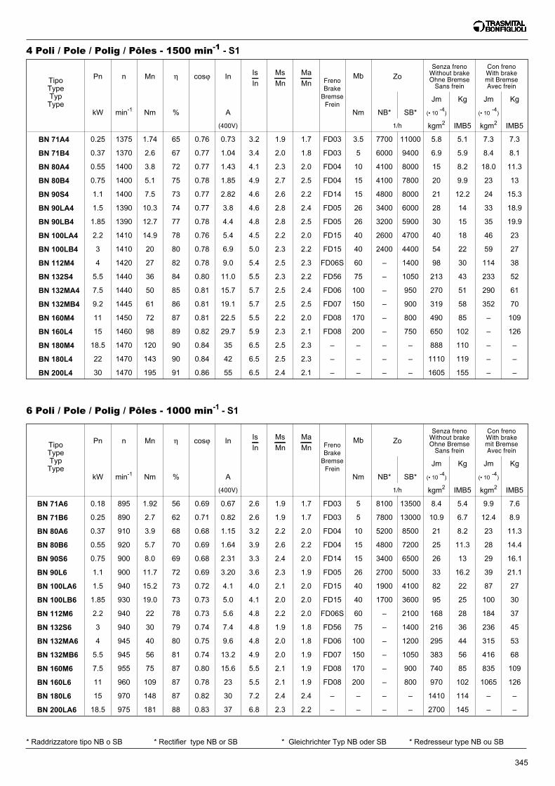
6 Poli / Pole / Polig / Pôles - 1000 min-1 - S1
TipoTypeTypType
Pn n Mn η cosϕ In Is
In
Ms
Mn
Ma
Mn FrenoBrakeBremseFrein
Mb Zo
Senza frenoWithout brakeOhne BremseSans frein
Con frenoWith brakemit BremseAvec frein
Jm Kg Jm Kg
kW min-1 Nm % A Nm NB* SB* (• 10-4) (• 10
-4)
(400V) 1/h kgm2 IMB5 kgm2 IMB5
BN 71A6 0.18 895 1.92 56 0.69 0.67 2.6 1.9 1.7 FD03 5 8100 13500 8.4 5.4 9.9 7.6
BN 71B6 0.25 890 2.7 62 0.71 0.82 2.6 1.9 1.7 FD03 5 7800 13000 10.9 6.7 12.4 8.9
BN 80A6 0.37 910 3.9 68 0.68 1.15 3.2 2.2 2.0 FD04 10 5200 8500 21 8.2 23 11.3
BN 80B6 0.55 920 5.7 70 0.69 1.64 3.9 2.6 2.2 FD04 15 4800 7200 25 11.3 28 14.4
BN 90S6 0.75 900 8.0 69 0.68 2.31 3.3 2.4 2.0 FD14 15 3400 6500 26 13 29 16.1
BN 90L6 1.1 900 11.7 72 0.69 3.20 3.6 2.3 1.9 FD05 26 2700 5000 33 16.2 39 21.1
BN 100LA6 1.5 940 15.2 73 0.72 4.1 4.0 2.1 2.0 FD15 40 1900 4100 82 22 87 27
BN 100LB6 1.85 930 19.0 73 0.73 5.0 4.1 2.0 2.0 FD15 40 1700 3600 95 25 100 30
BN 112M6 2.2 940 22 78 0.73 5.6 4.8 2.2 2.0 FD06S 60 – 2100 168 28 184 37
BN 132S6 3 940 30 79 0.74 7.4 4.8 1.9 1.8 FD56 75 – 1400 216 36 236 45
BN 132MA6 4 945 40 80 0.75 9.6 4.8 2.0 1.8 FD06 100 – 1200 295 44 315 53
BN 132MB6 5.5 945 56 81 0.74 13.2 4.9 2.0 1.9 FD07 150 – 1050 383 56 416 68
BN 160M6 7.5 955 75 87 0.80 15.6 5.5 2.1 1.9 FD08 170 – 900 740 85 835 109
BN 160L6 11 960 109 87 0.78 23 5.5 2.1 1.9 FD08 200 – 800 970 102 1065 126
BN 180L6 15 970 148 87 0.82 30 7.2 2.4 2.4 – – – – 1410 114 – –
BN 200LA6 18.5 975 181 88 0.83 37 6.8 2.3 2.2 – – – – 2700 145 – –
4 Poli / Pole / Polig / Pôles - 1500 min-1 - S1
TipoTypeTypType
Pn n Mn η cosϕ In Is
In
Ms
Mn
Ma
Mn FrenoBrakeBremseFrein
Mb Zo
Senza frenoWithout brakeOhne BremseSans frein
Con frenoWith brakemit BremseAvec frein
Jm Kg Jm Kg
kW min-1 Nm % A Nm NB* SB* (• 10-4) (• 10
-4)
(400V) 1/h kgm2 IMB5 kgm2 IMB5
BN 71A4 0.25 1375 1.74 65 0.76 0.73 3.2 1.9 1.7 FD03 3.5 7700 11000 5.8 5.1 7.3 7.3
BN 71B4 0.37 1370 2.6 67 0.77 1.04 3.4 2.0 1.8 FD03 5 6000 9400 6.9 5.9 8.4 8.1
BN 80A4 0.55 1400 3.8 72 0.77 1.43 4.1 2.3 2.0 FD04 10 4100 8000 15 8.2 18.0 11.3
BN 80B4 0.75 1400 5.1 75 0.78 1.85 4.9 2.7 2.5 FD04 15 4100 7800 20 9.9 23 13
BN 90S4 1.1 1400 7.5 73 0.77 2.82 4.6 2.6 2.2 FD14 15 4800 8000 21 12.2 24 15.3
BN 90LA4 1.5 1390 10.3 74 0.77 3.8 4.6 2.8 2.4 FD05 26 3400 6000 28 14 33 18.9
BN 90LB4 1.85 1390 12.7 77 0.78 4.4 4.8 2.8 2.5 FD05 26 3200 5900 30 15 35 19.9
BN 100LA4 2.2 1410 14.9 78 0.76 5.4 4.5 2.2 2.0 FD15 40 2600 4700 40 18 46 23
BN 100LB4 3 1410 20 80 0.78 6.9 5.0 2.3 2.2 FD15 40 2400 4400 54 22 59 27
BN 112M4 4 1420 27 82 0.78 9.0 5.4 2.5 2.3 FD06S 60 – 1400 98 30 114 38
BN 132S4 5.5 1440 36 84 0.80 11.0 5.5 2.3 2.2 FD56 75 – 1050 213 43 233 52
BN 132MA4 7.5 1440 50 85 0.81 15.7 5.7 2.5 2.4 FD06 100 – 950 270 51 290 61
BN 132MB4 9.2 1445 61 86 0.81 19.1 5.7 2.5 2.5 FD07 150 – 900 319 58 352 70
BN 160M4 11 1450 72 87 0.81 22.5 5.5 2.2 2.0 FD08 170 – 800 490 85 – 109
BN 160L4 15 1460 98 89 0.82 29.7 5.9 2.3 2.1 FD08 200 – 750 650 102 – 126
BN 180M4 18.5 1470 120 90 0.84 35 6.5 2.5 2.3 – – – – 888 110 – –
BN 180L4 22 1470 143 90 0.84 42 6.5 2.5 2.3 – – – – 1110 119 – –
BN 200L4 30 1470 195 91 0.86 55 6.5 2.4 2.1 – – – – 1605 155 – –
345
* Rectifier type NB or SB * Gleichrichter Typ NB oder SB * Redresseur type NB ou SB* Raddrizzatore tipo NB o SB
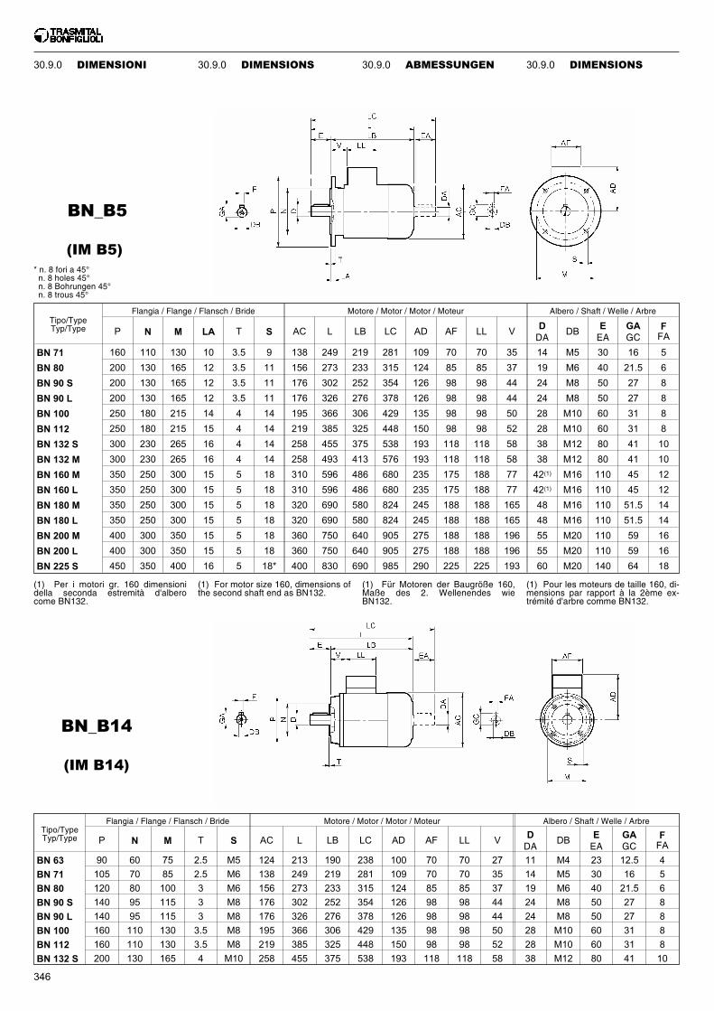
346
Tipo/TypeTyp/Type
Flangia / Flange / Flansch / Bride Motore / Motor / Motor / Moteur Albero / Shaft / Welle / Arbre
P N M T S AC L LB LC AD AF LL VDDA
DBEEA
GAGC
FFA
BN 63 90 60 75 2.5 M5 124 213 190 238 100 70 70 27 11 M4 23 12.5 4
BN 71 105 70 85 2.5 M6 138 249 219 281 109 70 70 35 14 M5 30 16 5
BN 80 120 80 100 3 M6 156 273 233 315 124 85 85 37 19 M6 40 21.5 6
BN 90 S 140 95 115 3 M8 176 302 252 354 126 98 98 44 24 M8 50 27 8
BN 90 L 140 95 115 3 M8 176 326 276 378 126 98 98 44 24 M8 50 27 8
BN 100 160 110 130 3.5 M8 195 366 306 429 135 98 98 50 28 M10 60 31 8
BN 112 160 110 130 3.5 M8 219 385 325 448 150 98 98 52 28 M10 60 31 8
BN 132 S 200 130 165 4 M10 258 455 375 538 193 118 118 58 38 M12 80 41 10
BN_B14
BN_B5
Tipo/TypeTyp/Type
Flangia / Flange / Flansch / Bride Motore / Motor / Motor / Moteur Albero / Shaft / Welle / Arbre
P N M LA T S AC L LB LC AD AF LL VDDA
DBEEA
GAGC
FFA
BN 71 160 110 130 10 3.5 9 138 249 219 281 109 70 70 35 14 M5 30 16 5
BN 80 200 130 165 12 3.5 11 156 273 233 315 124 85 85 37 19 M6 40 21.5 6
BN 90 S 200 130 165 12 3.5 11 176 302 252 354 126 98 98 44 24 M8 50 27 8
BN 90 L 200 130 165 12 3.5 11 176 326 276 378 126 98 98 44 24 M8 50 27 8
BN 100 250 180 215 14 4 14 195 366 306 429 135 98 98 50 28 M10 60 31 8
BN 112 250 180 215 15 4 14 219 385 325 448 150 98 98 52 28 M10 60 31 8
BN 132 S 300 230 265 16 4 14 258 455 375 538 193 118 118 58 38 M12 80 41 10
BN 132 M 300 230 265 16 4 14 258 493 413 576 193 118 118 58 38 M12 80 41 10
BN 160 M 350 250 300 15 5 18 310 596 486 680 235 175 188 77 42(1) M16 110 45 12
BN 160 L 350 250 300 15 5 18 310 596 486 680 235 175 188 77 42(1) M16 110 45 12
BN 180 M 350 250 300 15 5 18 320 690 580 824 245 188 188 165 48 M16 110 51.5 14
BN 180 L 350 250 300 15 5 18 320 690 580 824 245 188 188 165 48 M16 110 51.5 14
BN 200 M 400 300 350 15 5 18 360 750 640 905 275 188 188 196 55 M20 110 59 16
BN 200 L 400 300 350 15 5 18 360 750 640 905 275 188 188 196 55 M20 110 59 16
BN 225 S 450 350 400 16 5 18* 400 830 690 985 290 225 225 193 60 M20 140 64 18
(IM B14)
(IM B5)
* n. 8 fori a 45°n. 8 holes 45°n. 8 Bohrungen 45°n. 8 trous 45°
(1) For motor size 160, dimensions ofthe second shaft end as BN132.
(1) Für Motoren der Baugröße 160,Maße des 2. Wellenendes wieBN132.
(1) Pour les moteurs de taille 160, di-mensions par rapport à la 2ème ex-trémité d'arbre comme BN132.
(1) Per i motori gr. 160 dimensionidella seconda estremità d'alberocome BN132.
30.9.0 DIMENSIONI 30.9.0 ABMESSUNGEN30.9.0 DIMENSIONS 30.9.0 DIMENSIONS
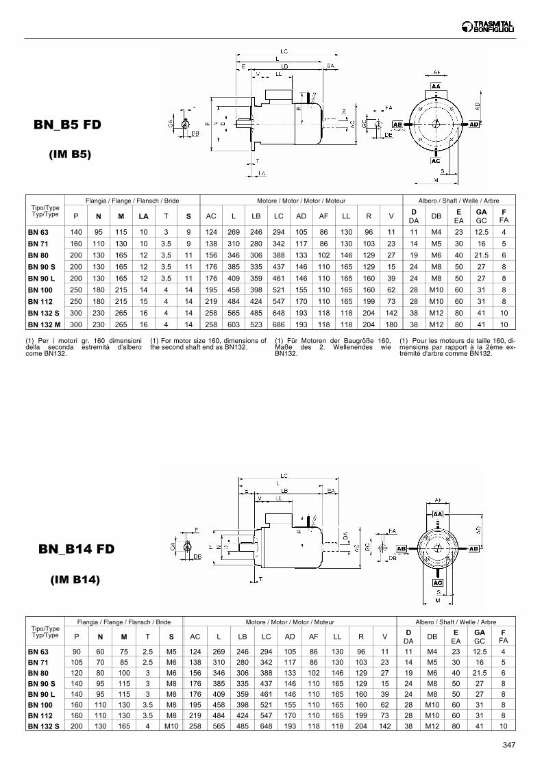
347
BN_B14 FD
BN_B5 FD
Tipo/TypeTyp/Type
Flangia / Flange / Flansch / Bride Motore / Motor / Motor / Moteur Albero / Shaft / Welle / Arbre
P N M LA T S AC L LB LC AD AF LL R VDDA
DBEEA
GAGC
FFA
BN 63 140 95 115 10 3 9 124 269 246 294 105 86 130 96 11 11 M4 23 12.5 4
BN 71 160 110 130 10 3.5 9 138 310 280 342 117 86 130 103 23 14 M5 30 16 5
BN 80 200 130 165 12 3.5 11 156 346 306 388 133 102 146 129 27 19 M6 40 21.5 6
BN 90 S 200 130 165 12 3.5 11 176 385 335 437 146 110 165 129 15 24 M8 50 27 8
BN 90 L 200 130 165 12 3.5 11 176 409 359 461 146 110 165 160 39 24 M8 50 27 8
BN 100 250 180 215 14 4 14 195 458 398 521 155 110 165 160 62 28 M10 60 31 8
BN 112 250 180 215 15 4 14 219 484 424 547 170 110 165 199 73 28 M10 60 31 8
BN 132 S 300 230 265 16 4 14 258 565 485 648 193 118 118 204 142 38 M12 80 41 10
BN 132 M 300 230 265 16 4 14 258 603 523 686 193 118 118 204 180 38 M12 80 41 10
Tipo/TypeTyp/Type
Flangia / Flange / Flansch / Bride Motore / Motor / Motor / Moteur Albero / Shaft / Welle / Arbre
P N M T S AC L LB LC AD AF LL R VDDA
DBEEA
GAGC
FFA
BN 63 90 60 75 2.5 M5 124 269 246 294 105 86 130 96 11 11 M4 23 12.5 4
BN 71 105 70 85 2.5 M6 138 310 280 342 117 86 130 103 23 14 M5 30 16 5
BN 80 120 80 100 3 M6 156 346 306 388 133 102 146 129 27 19 M6 40 21.5 6
BN 90 S 140 95 115 3 M8 176 385 335 437 146 110 165 129 15 24 M8 50 27 8
BN 90 L 140 95 115 3 M8 176 409 359 461 146 110 165 160 39 24 M8 50 27 8
BN 100 160 110 130 3.5 M8 195 458 398 521 155 110 165 160 62 28 M10 60 31 8
BN 112 160 110 130 3.5 M8 219 484 424 547 170 110 165 199 73 28 M10 60 31 8
BN 132 S 200 130 165 4 M10 258 565 485 648 193 118 118 204 142 38 M12 80 41 10
(IM B5)
(IM B14)
(1) For motor size 160, dimensions ofthe second shaft end as BN132.
(1) Für Motoren der Baugröße 160,Maße des 2. Wellenendes wieBN132.
(1) Pour les moteurs de taille 160, di-mensions par rapport à la 2ème ex-trémité d'arbre comme BN132.
(1) Per i motori gr. 160 dimensionidella seconda estremità d'alberocome BN132.
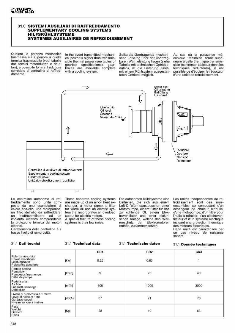
348
31.1 Technical data 31.1 Technische daten 31.1 Donnée techniques31.1 Dati tecnici
Qualora la potenza meccanicatrasmessa sia superiore a quellatermica trasmissibile (vedi tabelledati tecnici motoriduttori e ridut-tori), è possibile fornire il riduttorecorredato di centralina di raffred-damento.
Le centraline autonome di raf-freddamento sono unità com-poste da uno scambiatore dicalore aria-olio, una motopompa,un filtro dell'olio da raffreddare,un elettroventilatore ed unimpianto elettrico comprendentela protezione termica dei motorielettrici.Caratteristica delle centraline è ilbasso livello di rumorosità.
In the event transmitted mechani-cal power is higher than transmis-sible thermal power (see tables ofgearbox specifications), gear-boxes are available completewith a cooling system.
Sollte die übertragende mechani-sche Leistung über der übertrag-baren Wärmeleistung liegen (sieheTabelle mit technischen Getriebe-daten), ist die Lieferung eines,mit einem Kühlsystem ausgestat-teten Getriebe möglich.
Au cas où la puissance mé-canique transmise serait supé-rieure à celle thermique transmis-sible (confronter tableaux donnéestechniques réducteurs), il estpossible de d'équiper le réducteurd'une unité de refroidissement.
These separate cooling systemsare made up of an air-oil heat ex-changer, a motor pump, a filterfor warm oil and an electric sys-tem that incorporates an overloadcutout for electric motors.A special feature of these coolingsystems is their low noise.
Die autonomen Kühlsysteme sindEinheiten, die sich aus einemLuft-Öl-Wärmeaustauscher, einerMotorpumpe, einem Filter für daszu kühlende Öl, einem Elek-troventilator und einer elektri-schen Anlage, welche den Wär-meschutz der Elektromotorenenthält, zusammensetzen.
Les unités indépendantes de re-froidissement sont des sous-ensembles se composant d'unéchangeur de chaleur air/huile,d'une motopompe, d'un filtre pourl'huile à refroidir, d'un électroven-tilateur et d'un système électriqueincluant une protection thermiquedes moteurs électriques.Cette unité est caractérisée parun bas niveau de nuisancesonore.
CR1 CR2 CR3Potenza assorbitaPower absorbtionLeistungsaufnPuissance absorbée
[kW] 0.25 0.63 1
Portata pompaPumpflowPumpeausflussmengeDébit de pompe
[l/min] 9 25 40
Portata ariaAir flowLuftausflussmengeDébit d'air
[m3/h] 600 1000 3000
Livello di rumorosità a 1 metroLevel of noise at 1 mt.GeräuschpegelNiveau sonore à i mètre
[dB(A)] 67 71 76
PesoWeightGewichtPoids
[Kg] 28 40 63
31.0 SISTEMI AUSILIARI DI RAFFREDDAMENTOSUPPLEMENTARY COOLING SYSTEMSHILFSKÜHLSYSTEMESYSTEMES AUXILIAIRES DE REFROIDISSEMENT
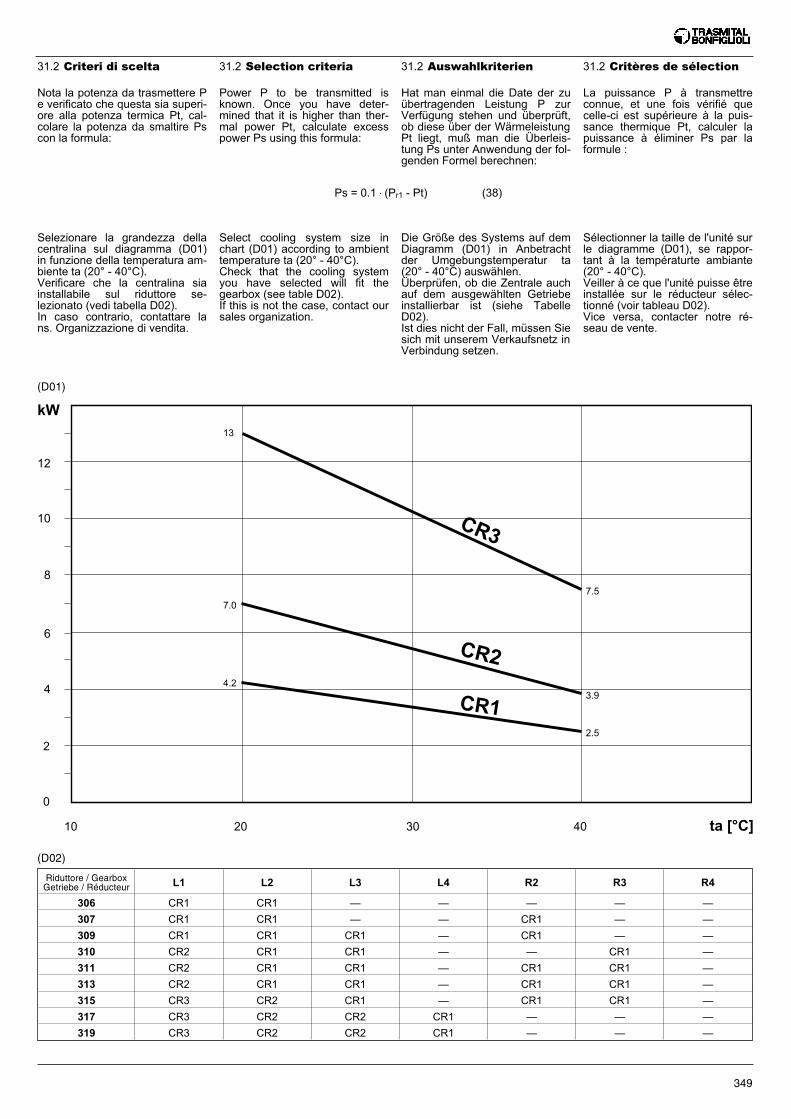
349
Select cooling system size inchart (D01) according to ambienttemperature ta (20° - 40°C).Check that the cooling systemyou have selected will fit thegearbox (see table D02).If this is not the case, contact oursales organization.
Die Größe des Systems auf demDiagramm (D01) in Anbetrachtder Umgebungstemperatur ta(20° - 40°C) auswählen.Überprüfen, ob die Zentrale auchauf dem ausgewählten Getriebeinstallierbar ist (siehe TabelleD02).Ist dies nicht der Fall, müssen Siesich mit unserem Verkaufsnetz inVerbindung setzen.
Sélectionner la taille de l'unité surle diagramme (D01), se rappor-tant à la températurte ambiante(20° - 40°C).Veiller à ce que l'unité puisse êtreinstallée sur le réducteur sélec-tionné (voir tableau D02).Vice versa, contacter notre ré-seau de vente.
31.2 Selection criteria 31.2 Auswahlkriterien 31.2 Critères de sélection31.2 Criteri di scelta
Nota la potenza da trasmettere Pe verificato che questa sia superi-ore alla potenza termica Pt, cal-colare la potenza da smaltire Pscon la formula:
Ps = 0.1 • (Pr1 - Pt) (38)
Power P to be transmitted isknown. Once you have deter-mined that it is higher than ther-mal power Pt, calculate excesspower Ps using this formula:
Hat man einmal die Date der zuübertragenden Leistung P zurVerfügung stehen und überprüft,ob diese über der WärmeleistungPt liegt, muß man die Überleis-tung Ps unter Anwendung der fol-genden Formel berechnen:
La puissance P à transmettreconnue, et une fois vérifié quecelle-ci est supérieure à la puis-sance thermique Pt, calculer lapuissance à éliminer Ps par laformule :
Selezionare la grandezza dellacentralina sul diagramma (D01)in funzione della temperatura am-biente ta (20° - 40°C).Verificare che la centralina siainstallabile sul riduttore se-lezionato (vedi tabella D02).In caso contrario, contattare lans. Organizzazione di vendita.
Riduttore / GearboxGetriebe / Réducteur L1 L2 L3 L4 R2 R3 R4
306 CR1 CR1 — — — — —
307 CR1 CR1 — — CR1 — —
309 CR1 CR1 CR1 — CR1 — —
310 CR2 CR1 CR1 — — CR1 —
311 CR2 CR1 CR1 — CR1 CR1 —
313 CR2 CR1 CR1 — CR1 CR1 —
315 CR3 CR2 CR1 — CR1 CR1 —
317 CR3 CR2 CR2 CR1 — — —
319 CR3 CR2 CR2 CR1 — — —
(D02)
(D01)
12
10
8
6
4
2
0
10 20
13
7.0
4.2
7.5
3.9
2.5
30 40
CR1
CR3
CR2
ta [°C]
kW
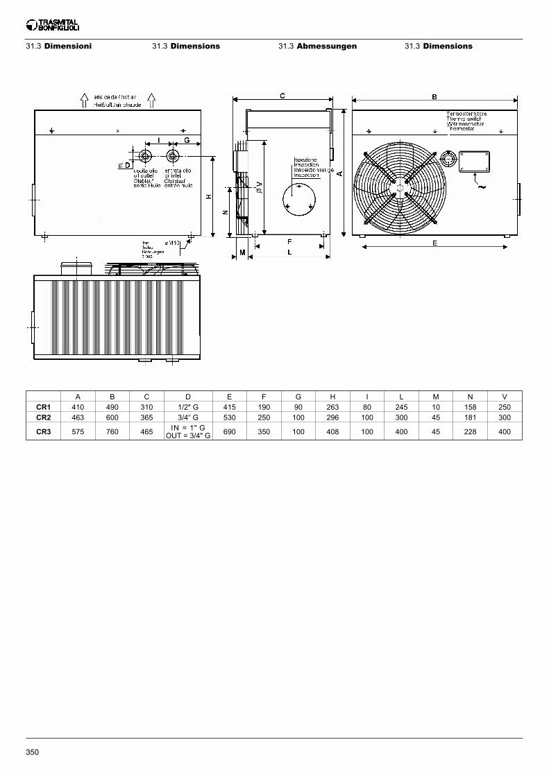
350
A B C D E F G H I L M N V
CR1 410 490 310 1/2" G 415 190 90 263 80 245 10 158 250
CR2 463 600 365 3/4“ G 530 250 100 296 100 300 45 181 300
CR3 575 760 465 IN = 1" GOUT = 3/4" G 690 350 100 408 100 400 45 228 400
31.3 Dimensions 31.3 Abmessungen 31.3 Dimensions31.3 Dimensioni

351
INDICE DELLE REVISIONI (R) INDEX OF REVISIONS (R) INDEX DES RÉVISIONS (R)
Questa pubblicazione annulla e sosti-tuisce ogni precedente edizione o re-visione. Ci riserviamo il diritto diapportare modifiche senza preavviso.E' vietata la riproduzione ancheparziale senza autorizzazione.
This publication cancels and replacesany previous edition and revision. Wereserve the right to implement modifi-cations without notice. This cataloguecannot be reproduced, even partially,without prior consent.
Diese Veröffentlichung annuliert undersetzt jeder hergehende Edition oderRevision. BONFIGLIOLI behält sichdas Recht vor, Änderungen ohne vor-herige Informationen durchzuführen.
Cette publication annule et remplacetoutes les autres précédentes. Nousnous réservons le droit d'apportertoutes modifications à nos produits.La reproduction et la publication par-tielle ou totale de ce catalogue est in-terdite sans notre autorisation.
LISTE DER ÄNDERUNGEN (R)
352
R2
Pag.: 32 - 176 - 206 - 209 - 215 - 217 - 219 - 225 - 244 - 254 - 255 - 264 - 265 - 266 - 268 - 274 - 278 - 279 - 284 - 285 - 288 - 289


![Y # % & Z 6 ( 7 2 g 'h 1 6 ( ) ! L A ( 7 6 ( ) L ... · E # R 7 8 ( ) m ] # 6 2 } F7 % G C 6 ( ) L pppA U % \ ( ) 9 7 = '| l i ( ) > ^ _ 6 ( ) @ A B C $ ( L A C / # ( ) L A _ (](https://img.pdfslide.fr/doc/110x75/5ecc2cebcc1c27130c003746/y-z-6-7-2-g-h-1-6-l-a-7-6-l-e-r-7-8-m-6-2.jpg)


![· 755@6& %& 476 > >@= ='h& ,& m]lqp (#&5"=& ljkm 4 6 7# 4 %z =" 6.>5& _ ;;7=? %& ;=(>&6? ?.76 ( 2)64" c ) '/056) 0..7/ - "6 $6 6 )/)6) - !" -f"/9)40//"."/6](https://img.pdfslide.fr/doc/110x75/5caab7f688c993e6068c00e0/-7556-476-h-mlqp-5-ljkm-4-6-7-4-z-65-7.jpg)