Embed Size (px)
Citation preview
Centre Scientifique et Technique du Bâtiment 84 avenue Jean Jaurès Champs sur Marne F-77447 Marne-la-Vallée Cedex 2 Tél. : (33) 01 64 68 82 82 Fax : (33) 01 60 05 70 37
Autorisé etnotifié conformément à
l’article 10 de la directive89/106/EEC du Conseil, du
21 décembre 1988, relative aurapprochement des dispositions
législatives, réglementaireset administratives des Etats
membres concernantles produits deconstruction.
MEMBRE DE L’EOTA
European Technical Approval ETA-08/0201 (English language translation, the original version is in French language)
Nom commercial : Trade name:
SPIT EPOBAR / EPOMAX
Titulaire : Holder of approval:
Société SPIT Route de Lyon BP 104 F 26501 BOURG-Lès-VALENCE France
Type générique et utilisation prévue du produit de construction :
Scellement d’armatures rapportées, diamètres 8 à 32mm, à l’aide la résine SPIT EPOBAR / EPOMAX
Generic type and use of construction product:
Post installed rebar connections diameter 8 to 32 mm made with SPIT EPOBAR / EPOMAX injection mortar.
Validité du : au : Validity from / to:
17/06/2013 17/06/2018
Usine de fabrication : Manufacturing plant:
Société SPIT Route de Lyon F-26501 BOURG-LES-VALENCE France
Le présent Agrément technique européen contient : This European Technical Approval contains:
22 pages incluant 13 annexes faisant partie intégrante du document. 22 pages including 13 annexes which form an integral part of the document.
This European Technical Approval cancels and replaces ETA-08/0201 with validity from 04/02/2008 to 23/07/2013.
Cet Agrément Technique Européen annule et remplace l’ETA-08/0201 valide du 04/02/2008 au 23/07/2013
Organisation pour l’Agrément Technique Européen
European Organisation for Technical Approvals
Page 2 of European technical approval ETA–08/0201, issued on 17/06/2013 English translation prepared by CSTB
I LEGAL BASES AND GENERAL CONDITIONS
1. This European Technical Approval is issued by the Centre Scientifique et Technique du Bâtiment in accordance with:
Council Directive 89/106/EEC of 21 December 1988 on the approximation of laws, regulations and administrative provisions of Member States relating to construction products1, modified by the Council Directive 93/68/EEC of 22 July 19932 and Regulation (EC) N° 1882/2003 of the European Parliament
and of the Council 3;
Décret n° 92-647 du 8 juillet 19924 concernant l’aptitude à l’usage des produits de construction; Common Procedural Rules for Requesting, Preparing and the Granting of European Technical Approvals set out in the Annex of Commission Decision 94/23/EC5; Guideline for European Technical Approval of « Metal Anchors for use in Concrete » ETAG 001, edition 1997, Part 1 « Anchors in general », Part 5 « Bonded anchors» and Technical Report for Post Installed Rebar Connections TR23.
2. The Centre Scientifique et Technique du Bâtiment is authorised to check whether the provisions of this European Technical Approval are met. Checking may take place in the manufacturing plant (for example concerning the fulfilment of assumptions made in this European Technical Approval with regard to manufacturing). Nevertheless, the responsibility for the conformity of the products with the European Technical Approval and for their fitness for the intended use remains with the holder of the European Technical Approval. 3. This European Technical Approval is not to be transferred to manufacturers or agents of manufacturer other than those indicated on page 1; or manufacturing plants other than those indicated on page 1 of this European Technical Approval. 4. This European Technical Approval may be withdrawn by the Centre Scientifique et Technique du Bâtiment pursuant to Article 5 (1) of the Council Directive 89/106/EEC. 5. Reproduction of this European Technical Approval including transmission by electronic means shall be in full. However, partial reproduction can be made with the written consent of the Centre Scientifique et Technique du Bâtiment. In this case partial reproduction has to be designated as such. Texts and drawings of advertising brochures shall not contradict or misuse the European Technical Approval. 6. The European Technical Approval is issued by the approval body in its official language. This version corresponds to the version circulated within EOTA. Translations into other languages have to be designated as such.
1 Official Journal of the European Communities n° L 40, 11.2.1989, p. 12 2 Official Journal of the European Communities n° L 220, 30.8.1993, p. 1 3 Official Journal of the European Union n° L 284, 31.10.2003, p. 25 4 Journal officiel de la République française du 14 juillet 1992 5 Official Journal of the European Communities n° L 17, 20.1.1994, p. 34
Page 3 of European technical approval ETA–08/0201, issued on 17/06/2013 English translation prepared by CSTB
II SPECIFIC CONDITIONS OF THE EUROPEAN TECHNICAL APPROVAL
1 Definition of product and intended use
1.1. Definition of product
The SPIT EPOBAR / EPOMAX is used for the connection, by anchoring or overlap joint, of reinforcing bars (rebars) in existing structures made of ordinary non-carbonated concrete C12/15 to C50/60. The design of the post-installed rebar connections is done in accordance with EN 1992-1-1 October 2005 (EN 1992-1-1).
Covered are rebar anchoring systems consisting of SPIT EPOBAR / EPOMAX bonding material and an embedded straight deformed reinforcing bar diameter, d, from 8 to 32 mm with properties according to Annex C of EN 1992-1-1 and EN 10080. The classes B and C of the rebar are recommended.
1.2. Intended use
The ETA covers applications in non-carbonated concrete C 12/15 to C 50/60 (EN 206-1) only, which are also allowed with straight deformed cast-in bars according to EN 1992-1-1, e.g. those in the following applications:
an overlapping joint with existing reinforcement in a building component, see Figure 1 and 2 in annex 4.
anchoring of the reinforcement at a slab or beam support; end support/bearing of a slab designed as simply supported as well as its reinforcement for restraint forces, see Figure 3 in annex 4.
anchoring of reinforcement of building components stressed primarily in compression, see Figure 4 in annex 4.
anchoring of reinforcement to cover the line of acting tensile force, see Figure 5 in annex 4.
The SPIT EPOBAR / EPOMAX anchoring systems can be used with the following limitations:
The rebars can be placed in holes made with hammer drilling technique or diamond drilling technique.
The rebars may be used in the following temperature range : -40°C to +80°C (max short term temperature +80°C and max long term temperature +50°C)
According to EN 206-1 the allowable chloride content in concrete is limited to 0.40 % (Cl 0,40) related to cement content.
The rebars may be installed in dry or wet concrete; it must not be in flooded holes. The rebar connections may be used for predominantly static loads
The fire resistance of post-installed rebar connections is not covered by this ETA.
Fatigue, dynamic or seismic loading of post-installed rebar connections are not covered by this ETA.
The provisions made in this European Technical Approval are based on an assumed intended working life of the rebar connections of 50 years. The indications given on the working life cannot be interpreted as a guarantee given by the producer, but are to be regarded only as a means for choosing the right products in relation to the expected economically reasonable working life of the works.
Page 4 of European technical approval ETA–08/0201, issued on 17/06/2013 English translation prepared by CSTB
2 Characteristics of product and methods of verification
2.1. Characteristics of product
The SPIT EPOBAR / EPOMAX injection adhesive corresponds to the drawings and provisions given in annexes 1 to 3.
The SPIT EPOBAR / EPOMAX injection adhesive described in annex 1 to 3 is a two components system. The two components of the injection mortar are delivered in unmixed condition in cartridges of sizes ranging from 345ml to 825ml. Each cartridge is marked with the identifying mark “SPIT EPOBAR”or “SPIT EPOMAX” with the charge code and the storage life.
2.2. Methods of verification
The assessment of fitness of the rebar connection for the intended use in relation to the requirements for mechanical resistance and stability and safety in use in the sense of the Essential Requirements 1 and 4 has been made in accordance with the « Guideline for European Technical Approval of Metal Anchors for use in Concrete », Part 1 « Anchors in general », Part 5 « Bonded anchors » and Technical Report n° 023 “Assessment of post installed rebar connections”.
In addition to the specific clauses relating to dangerous substances contained in this European Technical Approval, there may be other requirements applicable to the products falling within its scope (e.g. transposed European legislation and national laws, regulations and administrative provisions). In order to meet the provisions of the UE Construction Products Directive, these requirements need also to be complied with, when and where they apply.
3 Evaluation of Conformity and CE marking
3.1. Attestation of conformity system
The system of attestation of conformity 2 (i) (referred to as system 1) according to Council Directive 89/106/EEC Annex III laid down by the European Commission provides:
a) tasks for the manufacturer:
1. factory production control,
2. further testing of samples taken at the factory by the manufacturer in accordance with a prescribed test plan.
b) tasks for the approved body:
3. initial type-testing of the product,
4. initial inspection of factory and of factory production control,
5. continuous surveillance, assessment and approval of factory production control.
3.2. Responsibilities
3.2.1. Tasks of the manufacturer
3.2.1.1.Factory production control
The manufacturer shall have a factory production control system in the plant and shall exercise permanent internal control of production. All the elements, requirements and provisions adopted by the manufacturer are documented in a systematic manner in the form of written policies and
Page 5 of European technical approval ETA–08/0201, issued on 17/06/2013 English translation prepared by CSTB
procedures. This production control system ensures that the product is in conformity with the European Technical Approval.
The manufacturer shall only use raw materials supplied with the relevant inspection documents as
laid down in the prescribed test plan6. The incoming raw materials shall be subject to controls and tests by the manufacturer before acceptance. Check of incoming materials shall include control of the inspection documents presented by suppliers.
The frequency of controls and tests conducted during production is laid down in the prescribed test plan taking account of the automated manufacturing process of the product.
The results of factory production control are recorded and evaluated. The records shall be presented to the inspection body during the continuous surveillance. On request, they shall be presented to the Centre Scientifique et Technique du Bâtiment.
Details of the extent, nature and frequency of testing and controls to be performed within the factory production control shall correspond to the prescribed test plan which is part of the technical documentation of this European Technical Approval.
3.2.1.2.Other tasks of the manufacturer
The manufacturer shall, on the basis of a contract, involve a body which is approved for the tasks referred to in section 3.1 in the field of in order to undertake the actions laid down in section 3.2.2. For this purpose, the control plan referred to in sections 3.2.1 and 3.2.2 shall be handed over by the manufacturer to the approved body involved. The manufacturer shall make a declaration of conformity, stating that the construction product is in conformity with the provisions of this European technical approval.
3.2.2. Tasks of approved bodies
3.2.2.1. Initial type-testing of the product
For initial type-testing the results of the tests performed as part of the assessment for the European Technical Approval shall be used unless there are changes in the production line or plant. In such cases the necessary initial type-testing has to be agreed between the Centre Scientifique et Technique du Bâtiment and the approved bodies involved.
3.2.2.2. Initial inspection of factory and of factory production control
The approved body shall ascertain that, in accordance with the prescribed test plan, the factory and the factory production control are suitable to ensure continuous and orderly manufacturing of the anchor according to the specifications mentioned in 2.1. as well as to the Annexes to the European Technical Approval. The approved certification body involved by the manufacturer shall issue an EC certificate of conformity of the product stating the conformity with the provisions of this European technical approval.
3.2.2.3. Continuous surveillance
The approved certification body involved by the manufacturer shall visit the factory at least once a year for regular inspection. It has to be verified that the system of factory production control and the specified automated manufacturing process are maintained taking account of the prescribed test plan.
Continuous surveillance and assessment of factory production control have to be performed according to the prescribed test plan.
6 The prescribed test plan has been deposited at the Centre Scientifique et Technique du Bâtiment and is only made available
to the approved bodies involved in the conformity attestation procedure.

Page 6 of European technical approval ETA–08/0201, issued on 17/06/2013 English translation prepared by CSTB
The results of product certification and continuous surveillance shall be made available on demand by the certification body or inspection body, respectively, to the Centre Scientifique et Technique du Bâtiment. In cases where the provisions of the European Technical Approval and the prescribed test plan are no longer fulfilled the conformity certificate shall be withdrawn.
3.3. CE-Marking
The CE marking shall be affixed on each packaging of anchors. The symbol « CE » shall be accompanied by the following information:
Commercial name;
Name or identifying mark of the producer and manufacturing plant;
Name of approval body and ETA number;
Identification number of the certification body;
Number of the EC certificate of conformity;
Use category (ETAG 001-5);
The last two digits of the year in which the CE-marking was affixed;
Size.
4 Assumptions under which the fitness of the product for the intended use was favourably assessed
4.1. Manufacturing
The resin is manufactured in accordance with the provisions of the European Technical Approval using the automated manufacturing process as identified during inspection of the plant by the Centre Scientifique et Technique du Bâtiment and the approved body and laid down in the technical documentation. Changes to the product or production process, which could result in this deposited data/information being incorrect, should be notified to the Centre Scientifique et Technique du Bâtiment before the changes are introduced. The Centre Scientifique et Technique du Bâtiment will decide whether or not such changes affect the approval and consequently the validity of the CE marking on the basis of the approval and if so whether further assessment or alterations to the approval shall be necessary.
4.2. Drafting
Rebar connection must be designed in keeping with good engineering practice. Allowing for the loads to be anchored, design calculations and design drawings must be produced which can be checked. At least the following must be given in the design drawings:
Concrete strength. Diameter, drilling technique, concrete cover, spacing and anchorage depth of the rebars. Dimension for the depth of adhesive (dispensing amount to be marked on the mixer extension
as per annex 9, Kind of preparation of the joint between building component being connected.
4.3. Rebar connection design as per EN 1992-1-1
4.3.1. General points
The actual position of the reinforcement in the existing building component must be determined on the basis of the construction documentation and allowed for when drafting.
Page 7 of European technical approval ETA–08/0201, issued on 17/06/2013 English translation prepared by CSTB
The transfer of internal section forces in the joint must be verified in accordance to EN 1992-1-1 when a new building component is being connected. The transfer of shear forces between new and old concrete shall be designed according to EN 1992-1-1. The joints for concreting must be roughened to at least such an extent that aggregate protrude.
The design of rebar connections and determination of the internal section forces to be transferred in the construction joint shall be in keeping with the EN 1992-1-1.
Verification of immediate local force transfer to the concrete has been provided.
Verification of the transfer of the loads to be anchored to the building component must be provided.
4.3.2. Determination of anchorage depth.
4.3.2.1.General points
The design anchorage length lbd must be determined according to EN 1992-1-1, section 8.4.3. When the holes are done with diamond core drilling technique, the design values of bond stress for C20/25 shall be used for concrete of grades > C20/25.
The anchorage depths and overlap lengths must not be less than the minimum values given in annex 10. The maximum permissible anchorage depth is given in annex 6.
4.3.2.2.Calculation of the basic anchorage length lb,rqd
The basic anchorage length lb,rqd, for anchoring the force As.fyd in the rebar assuming constant bond stress equal to fbd follows from:
lb,rqd=(/4).(sd/fbd) where:
= diameter of the rebar
sd = calculated stress in the rebar under the design action fbd =design value of the bond strength according to table 4 & 5 in annex 11
4.3.2.3.Calculation of the minimum anchorage length lb,min
Anchoring rebar
In the case of anchoring rebar, the minimum anchorage length lb,min must be determined as follow.
For anchoring rebar in tension:
lb,mi,n = Max (0,3 lb,rqd; 10 ; 100mm) EN 1992-1-1 Equation 8.6
For anchoring rebar in compression:
lb,mi,n = Max (0,6 lb,rqd; 10 ; 100mm) EN 1992-1-1 Equation 8.7
Overlap joint
In the case of overlap joint, the minimum anchorage length l0,min must be determined as follow:
l0,min = Max (0,3.6.lb,rqd; 15 ; 200mm) EN 1992-1-1 Equation 8.11
Where .6.= (1/25)0.5≤ 1.5 1 is the percentage of reinforcement lapped within 0.65 l0 from the centre of the length considered.
4.3.2.4.Calculation of the design anchorage length lbd
Anchoring rebar
In the case of anchoring rebar, the design anchorage length lbd must be determined as follow:
lbd = 1 2 3 4 5 lb,rqd ≥ lb,min
Where 1, 2, 3, 4, 5 determined according to EN 1992-1-1.Table 8.2.
Page 8 of European technical approval ETA–08/0201, issued on 17/06/2013 English translation prepared by CSTB
Overlap joint
In the case of overlap joint, the design lap length l0 must be determined as follow:
l0 = 1 2 3 4 5 6 lb,rqd ≥ l0,min
Where 1, 2, 3, 4, 5, 6 determined according to, EN 1992-1-1.Table 8.2 and 8.3
1 Influence of the shape of the rebar 1=1 for straight rebar
2 Influence of the concrete cover 0.7 ≤��2 ≤ 1.0 calculated according to EN 1992-1-1 Table 8.2
3 Influence of the confinement by transverse reinforcement not welded to main reinforcement
3=1 because no transverse reinforcement
4 Influence of the confinement by welded transverse reinforcement
4=1 because no transverse reinforcement
5 Influence of the confinement by transverse pressure 0.7 ≤��5 ≤ 1.0
6 Influence of the overlapping length 1.0 ≤��6 ≤ 1.5
Nota: Examples of calculations are published in annexes 12 and 13 for concrete C20/25. Other values can be calculated by using the above formulas.
4.3.2.5.Transverse reinforcement
The transverse reinforcement required in the zone of the rebar connection must fulfil the requirement of EN 1992-1-1, section 8.7.4.
4.3.2.6 Connection joint In case of a connection being made between new and existing concrete where the surface layer of the existing concrete is carbonated, the layer should be removed in the area of the new reinforcing bar (with a diameter ds + 60mm) prior to the installation of the new bar. The foregoing may be neglected if building components are new and not carbonated.
4.3.2.7 Additional provisions
The concrete cover required for bonded-in rebars is shown in Annex 7, in relation to the drilling method. Furthermore the minimum concrete cover given in EN 1992-1-1, Section 4.4.1.2 shall be observed.
4.4. Installation
The fitness for use of the rebar connection can only be assumed if the rebar is installed as follows:
The installation of the post installed rebars shall be carried out according to the manufacturer’s installation instructions The installation of post-installed rebars shall be done only by suitable trained installer and under supervision on site. The conditions under which an installer may be considered as suitable trained and the conditions for supervision on site are up to the Member States in which the installation is done. Use of the system only as supplied by the manufacturer without exchanging the components of an system; Checks before placing the rebar to ensure that the strength class of the concrete in which the rebar is to be placed is in the range;
Page 9 of European technical approval ETA–08/0201, issued on 17/06/2013 English translation prepared by CSTB
The surface of the joint between new and existing concrete should be prepared (roughing, keying, according to the envisaged intended use according to EN 1992-1-1; Check of concrete being well compacted, e.g. without significant voids; Keeping the anchorage depth as specified in the design drawings; Keeping of the concrete cover and spacing as specified in the design drawings; The drilling and cleaning of the hole and the installation shall be performed only with the equipment as specified by the manufacturer given in annexes 6 to 9. It shall be ensured that this equipment is available on site and is used; Positioning of the drill holes without damaging the reinforcement; In case of aborted drill hole: the drill hole shall be filled with mortar; The post installed rebar connection must not be installed in flooded holes; Rebar installation ensuring the specified embedment depth, that is the appropriate depth marking of the rebar not exceeding the concrete surface;
4.5. Responsibility of the manufacturer
It is the manufacturer’s responsibility to ensure that the information on the specific conditions according to 1 and 2 including Annexes referred to in § 4.3. is given to those who are concerned. This information may be made by reproduction of the respective parts of the European Technical Approval. In addition all installation data shall be shown clearly on the package and/or on an enclosed instruction sheet, preferably using illustration(s).
The minimum data required are:
drill bit diameter, rebar diameter, admissible service temperature range, curing time of the bonding material depending on the installation temperature, information on the installation procedure, including cleaning of the hole, preferably by means of an illustration, reference to any special installation equipment needed, identification of the manufacturing batch.
All data shall be presented in a clear and explicit form.
5 Recommendations concerning packaging, transport and storage.
Each cartridge of resin is marked with the identifying mark of the producer, the trade name, the charge code, storage life, curing and processing time.
The cartridges of resin shall be protected against sun radiation and shall be stored according to the manufacturer’s installation instructions in dry conditions at temperatures of at least +0°C to not more than +35°C.
Mortar cartridges with expired shelf life must no longer be used.
The original French version is signed by
Le Directeur Technique C. BALOCHE
Page 10 of European technical approval ETA–08/0201, issued on 17/06/2013 English translation prepared by CSTB
Annex 1 of the European Technical Approval
ETA - 08/0201
SPIT EPOBAR / EPOMAX
EPOBAR PRODUCT DESCRIPTION
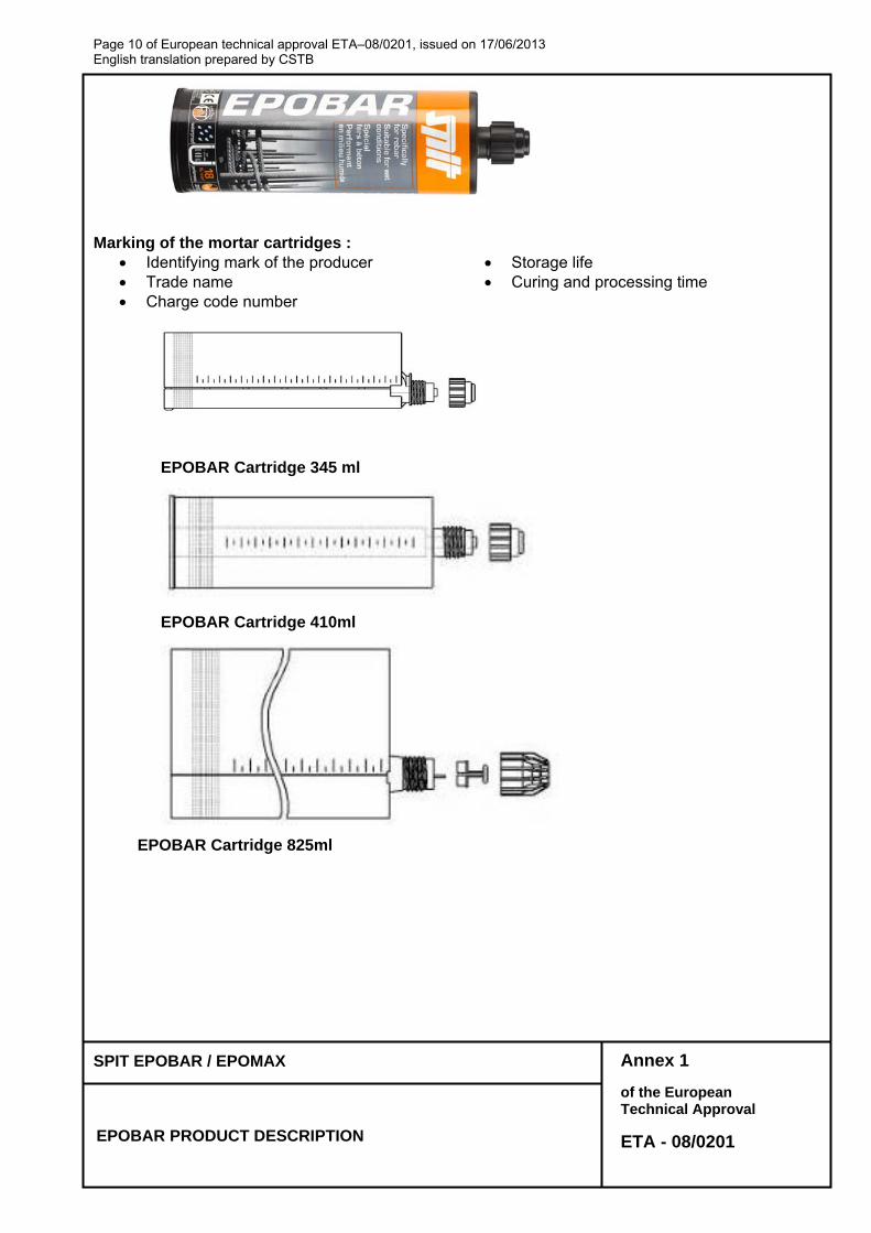
Marking of the mortar cartridges :
Identifying mark of the producer Storage life Trade name Curing and processing time Charge code number
EPOBAR Cartridge 345 ml
EPOBAR Cartridge 410ml
EPOBAR Cartridge 825ml
Page 11 of European technical approval ETA–08/0201, issued on 17/06/2013 English translation prepared by CSTB
Annex 2 of the European Technical Approval
ETA - 08/0201
SPIT EPOBAR / EPOMAX
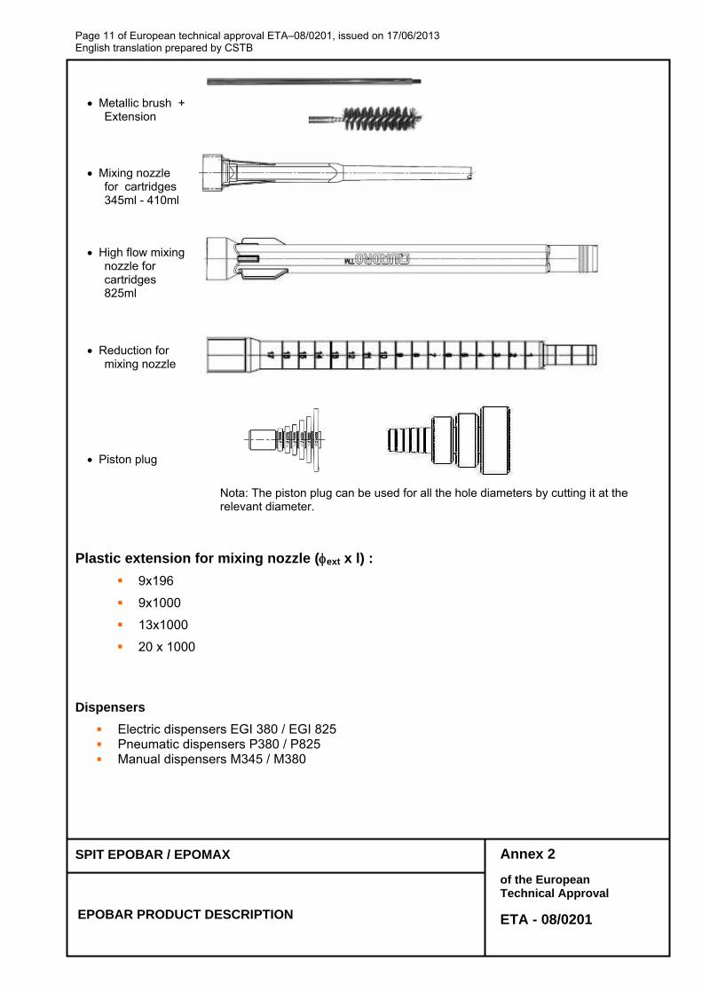
EPOBAR PRODUCT DESCRIPTION
Metallic brush + Extension
Mixing nozzle for cartridges 345ml - 410ml
High flow mixing nozzle for cartridges 825ml
Reduction for mixing nozzle
Piston plug
Nota: The piston plug can be used for all the hole diameters by cutting it at the relevant diameter.
Plastic extension for mixing nozzle (ext x l) :
9x196
9x1000
13x1000
20 x 1000
Dispensers
Electric dispensers EGI 380 / EGI 825 Pneumatic dispensers P380 / P825 Manual dispensers M345 / M380
Page 12 of European technical approval ETA–08/0201, issued on 17/06/2013 English translation prepared by CSTB
Annex 3 of the European Technical Approval
ETA - 08/0201
SPIT EPOBAR / EPOMAX
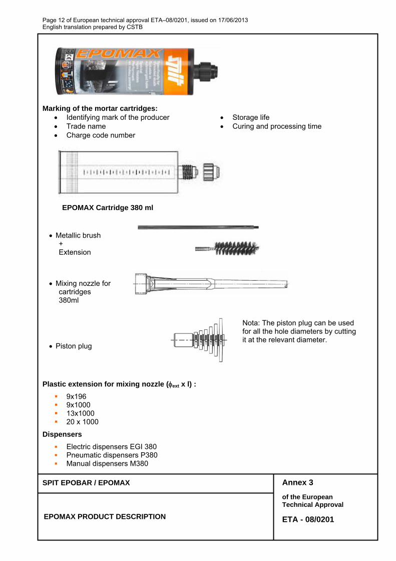
EPOMAX PRODUCT DESCRIPTION
Marking of the mortar cartridges: Identifying mark of the producer Storage life Trade name Curing and processing time Charge code number
EPOMAX Cartridge 380 ml
Metallic brush + Extension
Mixing nozzle for cartridges 380ml
Piston plug
Plastic extension for mixing nozzle (ext x l) :
9x196 9x1000 13x1000 20 x 1000
Dispensers
Electric dispensers EGI 380 Pneumatic dispensers P380 Manual dispensers M380
Nota: The piston plug can be used for all the hole diameters by cutting it at the relevant diameter.
Page 13 of European technical approval ETA–08/0201, issued on 17/06/2013 English translation prepared by CSTB
Annex 4 of the European Technical Approval
ETA - 08/0201
SPIT EPOBAR / EPOMAX
Intended use
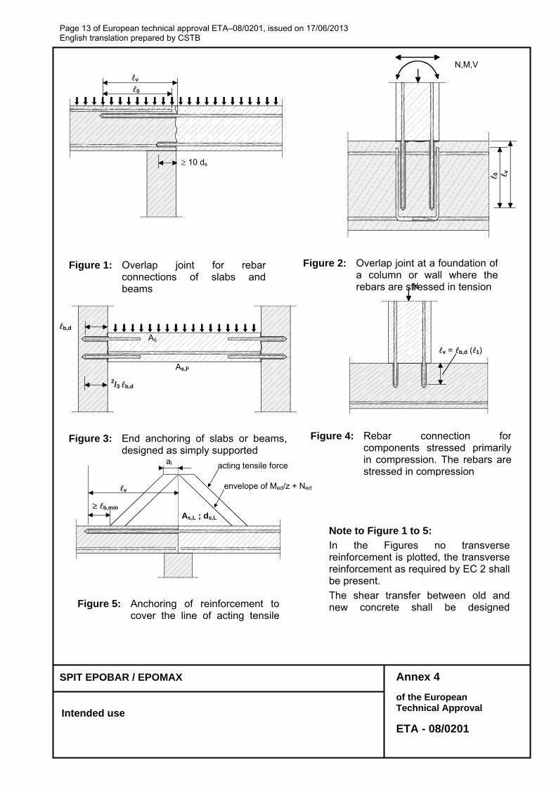
Figure 5: Anchoring of reinforcement tocover the line of acting tensile
Figure 1: Overlap joint for rebarconnections of slabs andbeams
Figure 2: Overlap joint at a foundation of a column or wall where the rebars are stressed in tension
N,M,V
0 v
0 v
10 ds
v = b,d (1)
N
Figure 4: Rebar connection for components stressed primarily in compression. The rebars are stressed in compression
b,d
2/3 b,d
As
As,F
Figure 3: End anchoring of slabs or beams,designed as simply supported
acting tensile force
b,min As,L ; ds,L
v
al
envelope of Med/z + Ned
Note to Figure 1 to 5:
In the Figures no transversereinforcement is plotted, the transversereinforcement as required by EC 2 shallbe present.
The shear transfer between old andnew concrete shall be designed
Page 14 of European technical approval ETA–08/0201, issued on 17/06/2013 English translation prepared by CSTB
Annex 5 of the European Technical Approval
ETA - 08/0201
SPIT EPOBAR / EPOMAX
Reinforcing bar “rebar” according to EC2
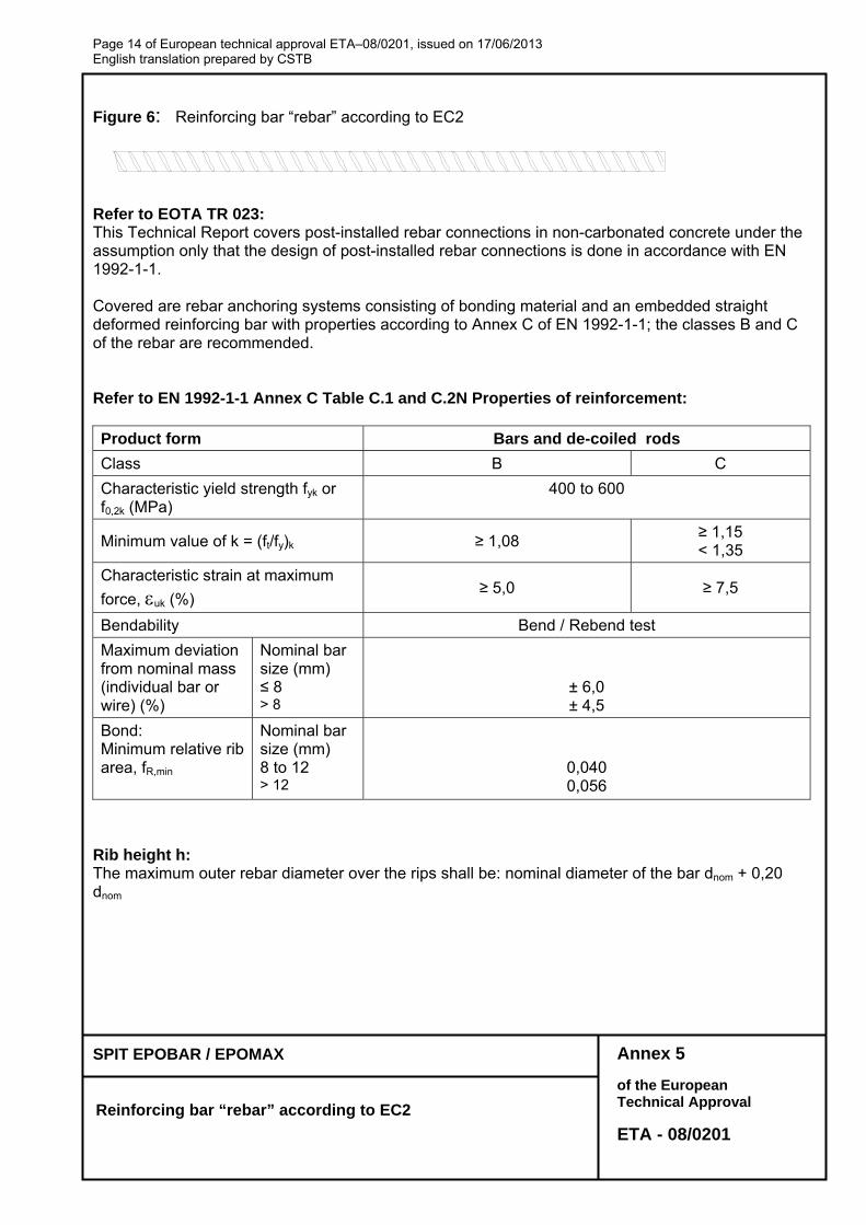
Figure 6: Reinforcing bar “rebar” according to EC2
Refer to EOTA TR 023: This Technical Report covers post-installed rebar connections in non-carbonated concrete under the assumption only that the design of post-installed rebar connections is done in accordance with EN 1992-1-1. Covered are rebar anchoring systems consisting of bonding material and an embedded straight deformed reinforcing bar with properties according to Annex C of EN 1992-1-1; the classes B and C of the rebar are recommended. Refer to EN 1992-1-1 Annex C Table C.1 and C.2N Properties of reinforcement: Product form Bars and de-coiled rods
Class B C
Characteristic yield strength fyk or f0,2k (MPa)
400 to 600
Minimum value of k = (ft/fy)k ≥ 1,08 ≥ 1,15 < 1,35
Characteristic strain at maximum
force, uk (%) ≥ 5,0 ≥ 7,5
Bendability Bend / Rebend test
Maximum deviation from nominal mass (individual bar or wire) (%)
Nominal bar size (mm) ≤ 8 > 8
± 6,0 ± 4,5
Bond: Minimum relative rib area, fR,min
Nominal bar size (mm) 8 to 12 > 12
0,040 0,056
Rib height h: The maximum outer rebar diameter over the rips shall be: nominal diameter of the bar dnom + 0,20 dnom
Page 15 of European technical approval ETA–08/0201, issued on 17/06/2013 English translation prepared by CSTB
Annex 6 of the European Technical Approval
ETA - 08/0201
SPIT EPOBAR / EPOMAX
Installation instructions of the rebars
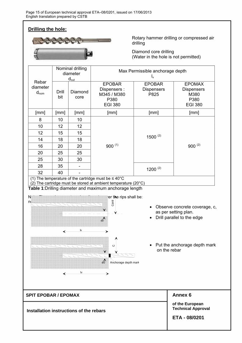
Drilling the hole:
Rotary hammer drilling or compressed air drilling
Diamond core drilling (Water in the hole is not permitted)
Rebar diameter
dnom
Nominal drilling diameter
dcut
Max Permissible anchorage depth lv
Drill bit
Diamond core
EPOBAR Dispensers : M345 / M380
P380 EGI 380
EPOBAR Dispensers
P825
EPOMAX Dispensers
M380 P380
EGI 380
[mm] [mm] [mm] [mm] [mm] [mm]
8 10 10
900 (1)
1500 (2)
900 (2)
10 12 12
12 15 15
14 18 18
16 20 20
20 25 25
25 30 30
28 35 - 1200 (2)
32 40 - (1) The temperature of the cartridge must be ≤ 40°C (2) The cartridge must be stored at ambient temperature (20°C)
Table 1:Drilling diameter and maximum anchorage length Nota: The maximum outer rebar diameter over the rips shall be: nominal diameter of the bar dnom + 0,20 dnom Observe concrete coverage, c,
as per setting plan. Drill parallel to the edge
lv
d0
C
Anchorage depth mark
Put the anchorage depth mark on the rebar
lv
d0
Cd
rill
Page 16 of European technical approval ETA–08/0201, issued on 17/06/2013 English translation prepared by CSTB
Annex 7 of the European Technical Approval
ETA - 08/0201
SPIT EPOBAR / EPOMAX
Installation instructions of the rebars
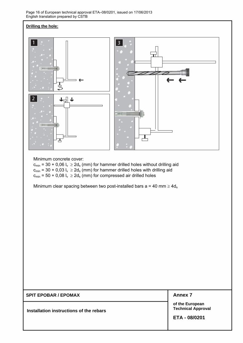
Drilling the hole:
Minimum concrete cover: cmin = 30 + 0,06 lv 2ds (mm) for hammer drilled holes without drilling aid cmin = 30 + 0,03 lv 2ds (mm) for hammer drilled holes with drilling aid cmin = 50 + 0,08 lv 2ds (mm) for compressed air drilled holes
Minimum clear spacing between two post-installed bars a = 40 mm 4ds
Page 17 of European technical approval ETA–08/0201, issued on 17/06/2013 English translation prepared by CSTB
Annex 8 of the European Technical Approval
ETA - 08/0201
SPIT EPOBAR / EPOMAX
Installation instructions of the rebars
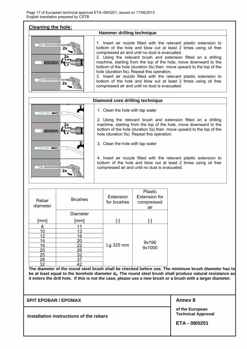
Cleaning the hole: Hammer drilling technique
1. Insert air nozzle fitted with the relevant plastic extension to bottom of the hole and blow out at least 2 times using oil free compressed air and until no dust is evacuated. 2. Using the relevant brush and extension fitted on a drilling machine, starting from the top of the hole, move downward to the bottom of the hole (duration 5s) then move upward to the top of the hole (duration 5s). Repeat this operation. 3. Insert air nozzle fitted with the relevant plastic extension to bottom of the hole and blow out at least 2 times using oil free compressed air and until no dust is evacuated.
Diamond core drilling technique
1. Clean the hole with tap water 2. Using the relevant brush and extension fitted on a drilling machine, starting from the top of the hole, move downward to the bottom of the hole (duration 5s) then move upward to the top of the hole (duration 5s). Repeat this operation. 3. Clean the hole with tap water 4. Insert air nozzle fitted with the relevant plastic extension to bottom of the hole and blow out at least 2 times using oil free compressed air and until no dust is evacuated.
Rebar diameter
Brushes Extension
for brushes
Plastic Extension for compressed
air
Diameter
[mm] [mm] [-] [-] 8 11
Lg 325 mm 9x196
9x1000
10 13 12 16 14 20 16 22 20 26 25 32 28 37 32 42
The diameter of the round steel brush shall be checked before use. The minimum brush diameter has to be at least equal to the borehole diameter d0. The round steel brush shall produce natural resistance as it enters the drill hole. If this is not the case, please use a new brush or a brush with a larger diameter.
Page 18 of European technical approval ETA–08/0201, issued on 17/06/2013 English translation prepared by CSTB
Annex 9 of the European Technical Approval
ETA - 08/0201
SPIT EPOBAR / EPOMAX
Installation instructions of the rebars
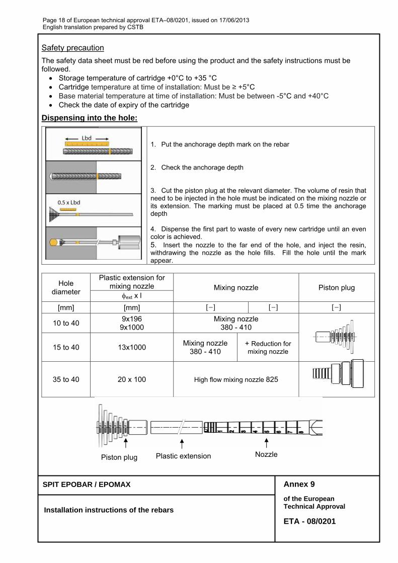
Safety precaution
The safety data sheet must be red before using the product and the safety instructions must be followed. Storage temperature of cartridge +0°C to +35 °C Cartridge temperature at time of installation: Must be ≥ +5°C Base material temperature at time of installation: Must be between -5°C and +40°C Check the date of expiry of the cartridge
Dispensing into the hole:
1. Put the anchorage depth mark on the rebar 2. Check the anchorage depth 3. Cut the piston plug at the relevant diameter. The volume of resin that need to be injected in the hole must be indicated on the mixing nozzle or its extension. The marking must be placed at 0.5 time the anchorage depth 4. Dispense the first part to waste of every new cartridge until an even color is achieved. 5. Insert the nozzle to the far end of the hole, and inject the resin, withdrawing the nozzle as the hole fills. Fill the hole until the mark appear.
Hole diameter
Plastic extension for mixing nozzle Mixing nozzle Piston plug
ext x l
[mm] [mm]
10 to 40 9x196
9x1000 Mixing nozzle
380 - 410
15 to 40 13x1000 Mixing nozzle
380 - 410 + Reduction for mixing nozzle
35 to 40 20 x 100 High flow mixing nozzle 825
Piston plug Plastic extension Nozzle
Page 19 of European technical approval ETA–08/0201, issued on 17/06/2013 English translation prepared by CSTB
Annex 10 of the European Technical Approval
ETA - 08/0201
SPIT EPOBAR / EPOMAX
Installation instructions of the rebars
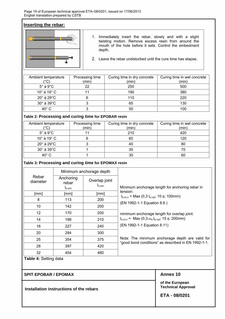
Inserting the rebar:
1. Immediately insert the rebar, slowly and with a slight
twisting motion. Remove excess resin from around the mouth of the hole before it sets. Control the embedment depth.
2. Leave the rebar undisturbed until the cure time has elapse.
Ambient temperature
(°C) Processing time
(min) Curing time in dry concrete
(min) Curing time in wet concrete
(min) 5° à 9°C 22 250 500
10° à 19° C 11 190 380
20° à 29°C 6 110 220
30° à 39°C 3 65 130
40° C 3 50 100
Table 2: Processing and curing time for EPOBAR resin
Ambient temperature (°C)
Processing time (min)
Curing time in dry concrete (min)
Curing time in wet concrete(min)
5° à 9°C 11 210 420
10° à 19° C 6 60 120
20° à 29°C 3 40 80
30° à 39°C 1 35 70
40° C 1 30 60
Table 3: Processing and curing time for EPOMAX resin
Rebar diameter
Minimum anchorage depth Minimum anchorage length for anchoring rebar in tension: lb,mi,n = Max (0,3 lb,rqd; 10 ; 100mm)
(EN 1992-1-1 Equation 8.6 )
minimum anchorage length for overlap joint: l0,mi,n = Max (0,3.6.lb,rqd; 15 ; 200mm)
(EN 1992-1-1 Equation 8.11)
Nota: The minimum anchorage depth are valid for “good bond conditions” as described in EN 1992-1-1.
Anchoring rebar lb,min
Overlap joint l0,min
[mm] [mm] [mm]
8 113 200
10 142 200
12 170 200
14 198 210
16 227 240
20 284 300
25 354 375
28 397 420
32 454 480
Table 4: Setting data
Page 20 of European technical approval ETA–08/0201, issued on 17/06/2013 English translation prepared by CSTB
Annex 11 of the European Technical Approval
ETA - 08/0201
SPIT EPOBAR / EPOMAX
Design values
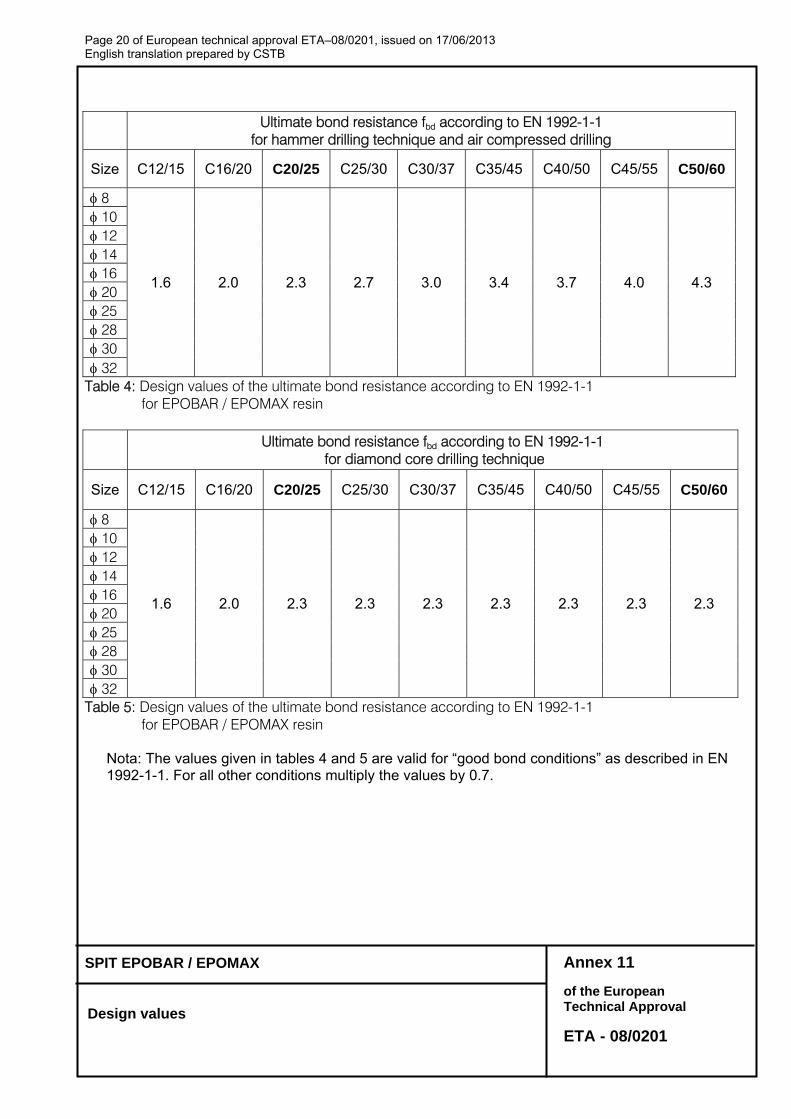
Ultimate bond resistance fbd according to EN 1992-1-1
for hammer drilling technique and air compressed drilling
Size C12/15 C16/20 C20/25 C25/30 C30/37 C35/45 C40/50 C45/55 C50/60
8
1.6 2.0 2.3 2.7 3.0 3.4 3.7 4.0 4.3
10 12 14 16 20 25 28 30 32
Table 4: Design values of the ultimate bond resistance according to EN 1992-1-1 for EPOBAR / EPOMAX resin
Ultimate bond resistance fbd according to EN 1992-1-1
for diamond core drilling technique
Size C12/15 C16/20 C20/25 C25/30 C30/37 C35/45 C40/50 C45/55 C50/60
8
1.6 2.0 2.3 2.3 2.3 2.3 2.3 2.3 2.3
10 12 14 16 20 25 28 30 32
Table 5: Design values of the ultimate bond resistance according to EN 1992-1-1 for EPOBAR / EPOMAX resin
Nota: The values given in tables 4 and 5 are valid for “good bond conditions” as described in EN 1992-1-1. For all other conditions multiply the values by 0.7.

Page 21 of European technical approval ETA–08/0201, issued on 17/06/2013 English translation prepared by CSTB
Annex 12 of the European Technical Approval
ETA - 08/0201
SPIT EPOBAR / EPOMAX
Design values
SPIT EPOBAR / EPOMAX – Anchoring of Rebar HA Fe E500 – C20/25 concrete (fbd=2.3Mpa)
Reb
ar
Ø 1=2=3=4=5=1,0 2 or 5= 0,71 = 3 = 4 = 1,0
Anchorage length lbd
Tension load Mortar
volume V Anchorage length
lbd Tension load
Mortar volume V
[mm] [mm] [kN] [ml] [mm] [kN] [ml]
8
113 * 6.56 4 113 * 9.37 4 170 9.83 6 150 12.39 5 240 13.87 8 180 14.86 6 310 17.92 11 220 18.17 7 378 21.85 13 265 21.85 9
10
142 * 10.24 6 142 * 14.63 6 220 15.90 9 180 18.58 7 300 21.68 12 230 23.74 10 380 27.46 16 280 28.90 12 473 34.15 20 331 34.15 14
12
170 * 14.75 13 170 * 21.07 13 260 22.54 20 220 27.25 17 360 31.21 27 280 34.68 21 460 39.89 35 340 42.12 26 567 49.17 43 397 49.17 30
14
198 * 20.08 24 198 * 28.68 24 310 31.36 37 260 37.57 31 430 43.50 52 330 47.69 40 540 54.63 65 390 56.36 47 662 66.93 80 463 66.93 56
16
227 * 26.23 31 227 * 37.46 31 350 40.46 48 300 49.55 41 490 56.65 67 370 61.11 50 620 71.68 84 450 74.32 61 756 87.42 103 529 87.42 72
20
284 * 40.98 60 284 * 58.54 60 430 62.14 91 370 76.39 78 590 85.26 125 470 97.03 100 740 106.94 157 560 115.61 119 900 130.06 191 662 136.59 140
25
354 * 64.03 92 354 * 91.47 92 490 88.51 127 470 121.29 122 620 112.00 161 590 152.26 153 760 137.29 197 700 180.64 181 900 162.58 233 827 213.42 214
28
397 * 80.32 165 397 * 114.74 165 520 105.21 216 520 150.29 216 640 129.48 266 640 184.98 266 770 155.79 320 770 222.55 320 900 182.09 374 900 260.12 374
32
454 * 104.90 246 454 * 149.86 246 560 129.48 304 560 184.98 304 670 154.92 364 670 221.31 364 780 180.35 423 780 257.65 423 900 208.10 489 900 297.28 489
1) Tabulated maximum tension loads are valid for good bond conditions according to EN 1992-1-1. For all other bond conditions the values for tension loads must be multiplied by 0.7.
2) The volume V of mortar can be estimated using the equation V = 1.2.(do²-d²).lbd/4 * Values corresponding to the minimum anchorage length lb,min
Page 22 of European technical approval ETA–08/0201, issued on 17/06/2013 English translation prepared by CSTB
Annex 13 of the European Technical Approval
ETA - 08/0201
SPIT EPOBAR / EPOMAX
Design values
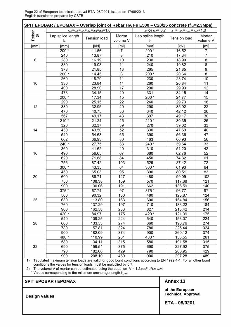
SPIT EPOBAR / EPOMAX – Overlap joint of Rebar HA Fe E500 – C20/25 concrete (fbd=2.3Mpa)
Reb
ar
Ø
1=2=3=4=5=6=1,0 2 or 5= 0,71 = 3 = 4 = 6=1,0
Lap splice length l0
Tension load Mortar
volume V Lap splice length
l0 Tension load
Mortar volume V
[mm] [mm] [kN] [ml] [mm] [kN] [ml]
8
200 * 11.56 7 200 * 16.52 7 240 13.87 8 210 17.34 7 280 16.19 10 230 18.99 8 330 19.08 11 240 19.82 8 378 21.85 13 265 21.85 9
10
200 * 14.45 8 200 * 20.64 8 260 18.79 11 230 23.74 10 330 23.84 14 260 26.84 11 400 28.90 17 290 29.93 12 473 34.15 20 331 34.15 14
12
200 * 17.34 15 200 * 24.77 15 290 25.15 22 240 29.73 18 380 32.95 29 290 35.92 22 470 40.75 36 340 42.12 26 567 49.17 43 397 49.17 30
14
210 * 21.24 25 210 * 30.35 25 320 32.37 39 270 39.02 33 430 43.50 52 330 47.69 40 540 54.63 65 390 56.36 47 662 66.93 80 463 66.93 56
16
240 * 27.75 33 240 * 39.64 33 360 41.62 49 310 51.20 42 490 56.65 67 380 62.76 52 620 71.68 84 450 74.32 61 756 87.42 103 529 87.42 72
20
300 * 43.35 64 300 * 61.93 64 450 65.03 95 390 80.51 83 600 86.71 127 480 99.09 102 750 108.38 159 570 117.68 121 900 130.06 191 662 136.59 140
25
375 * 67.74 97 375 * 96.77 97 500 90.32 130 480 123.87 124 630 113.80 163 600 154.84 156 760 137.29 197 710 183.22 184 900 162.58 233 827 213.42 214
28
420 * 84.97 175 420 * 121.39 175 540 109.25 224 540 156.07 224 660 133.53 274 660 190.76 274 780 157.81 324 780 225.44 324 900 182.09 374 900 260.12 374
32
480 * 110.99 261 480 * 158.55 261 580 134.11 315 580 191.58 315 690 159.54 375 690 227.92 375 790 182.66 429 790 260.95 429 900 208.10 489 900 297.28 489
1) Tabulated maximum tension loads are valid for good bond conditions according to EN 1992-1-1. For all other bond conditions the values for tension loads must be multiplied by 0.7.
2) The volume V of mortar can be estimated using the equation V = 1.2.(do²-d²).lbd/4 * Values corresponding to the minimum anchorage length l0,min


![[halshs-00458968, v1] Les effets de l'adoption obligatoire ... · PDF fileCet article examine les effets de l adoption obliga toire des IFRS sur les ... développés en interne.](https://img.pdfslide.fr/doc/110x75/5ab3bcfd7f8b9a6b468eafbd/halshs-00458968-v1-les-effets-de-ladoption-obligatoire-article-examine-les.jpg)