Embed Size (px)
Citation preview
8/7/2019 Léopard 2 - 4x2 -
http://slidepdf.com/reader/full/leopard-2-4x2- 1/24
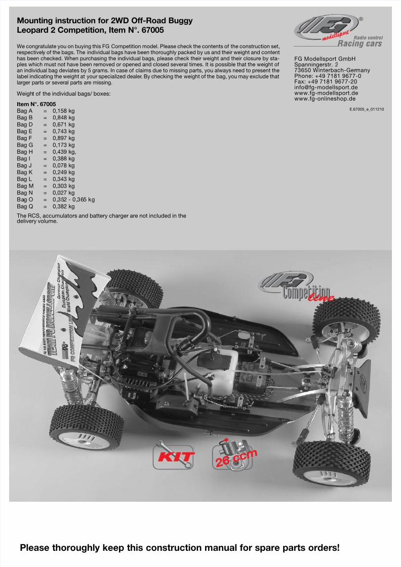
Weight of the individual bags/ boxes:
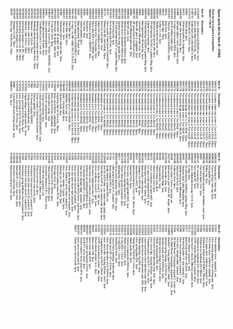
Item N°. 67005
Bag A = 0,158 kg
Bag B = 0,848 kg
Bag D = 0,671 kg
Bag E = 0,743 kg
Bag F = 0,897 kg
Bag G = 0,173 kg
Bag H = 0,439 kg,
Bag I = 0,388 kg
Bag J = 0,078 kg
Bag K = 0,249 kg
Bag L = 0,343 kg
Bag M = 0,303 kg
Bag N = 0,027 kg
Bag O = 0,352 - 0,365 kgBag Q = 0,382 kg
The RCS, accumulators and battery charger are not included in thedelivery volume.
E.67005_e_011210
FG Modellsport GmbHSpanningerstr. 273650 Winterbach-GermanyPhone: +49 7181 9677-0Fax: +49 7181 [email protected]
www.fg-onlineshop.de
We congratulate you on buying this FG Competition model. Please check the contents of the construction set,respectively of the bags. The individual bags have been thoroughly packed by us and their weight and contenthas been checked. When purchasing the individual bags, please check their weight and their closure by sta-ples which must not have been removed or opened and closed several times. It is possible that the weight ofan individual bag deviates by 5 grams. In case of claims due to missing parts, you always need to present thelabel indicating the weight at your specialized dealer. By checking the weight of the bag, you may exclude thatlarger parts or several parts are missing.
Mounting instruction for 2WD Off-Road Buggy
Leopard 2 Competition, Item N°. 67005
Please thoroughly keep this construction manual for spare parts orders!
8/7/2019 Léopard 2 - 4x2 -
http://slidepdf.com/reader/full/leopard-2-4x2- 2/24
The handling with fuels requires circumspective and ca-
reful handling. Imperatively observe the security advices.
- Refuel only if the engine is switched off!- Take off the body.- Thoroughly clean the area around the fuels nipple.- Remove the fuel filler cap and carefully fill in the fuel mixture.- Smoking or any kind of open fire is not admitted.- Fuels might contain solvent-like substances. Avoid contact with skin and
eyes. Wear gloves for refueling. Do not inhale fuel vapors.- Do not spill any fuel. If you have spilled fuel immediately clean the engi-
ne and the model.- Make sure that no fuel will get into the soils (environmental protection).
Use an appropriate mat.- Do not refuel in enclosed rooms. Fuel vapors accumulate at the soil (riskof explosion).
- Transport and store fuels only in admitted and labeled canisters. Keepfuel out of the range of children.
- The operator is responsible for any damages caused to third persons inthe operating range of the model, respectively of the engine, if they areinjured or in case of property damage.
- The model must only be passed on to persons who are familiar with thismodel and its operation, always provide the operating manual.
- Persons with implanted heart pacemakers must not work on running en-gines and on live parts of the ignition system when the engine is beingstarted.
- The engine must neither be started nor operated in enclosed rooms (wi-thout sufficient ventilation).
- When starting the engine, avoid inhaling the exhausts.- The model must neither be started nor operated without air filter or wi-
thout exhaust system.- Before every start perform a functional check of the safety-relevant parts.- The throttle rods must always return automatically to the idle position.- Any cleaning, maintenance and repair works must only be performed
with the engine being switched off. The engine and silencers are gettingvery hot. In particular do not touch the silencer.
Comments regarding the construction manual:
Before starting the assembly please see through this construction manu-al. This way you will get an overview of the whole execution.
Please check by means of the parts or bag list if the construction kit is com-plete and also check the weight of the individual bags for the positions.Only this way you may be sure that all parts which you need for the as-sembly are available. If a part is missing, please immediately contact yourspecialized dealer.
Table of contents
Position 1: CFRP chassis stiffening, ABS splash guards, battery
holderPosition 2: Differential gear
Position 3,4: Aluminium rear axle mounts, rear lower wishbones
Position 5-7: Rear axle
Position 8: Shock absorbers
Position 9: Shock mount, spoiler mount, rear damper protection
Position 10-15: Engine, air filter, gear, fuel tank
Position 16-18: Roll bar, tuning pipe, starter rope
Position 19-24: Servos, receiver box, servo saver
Position 25,26: Front lower wishbones, stabilizer, front axle plate
Position 27-29: Front axle, uprights, front bumper
Position 30,31: Throttle rods
Position 32-35: Hydraulic brake system
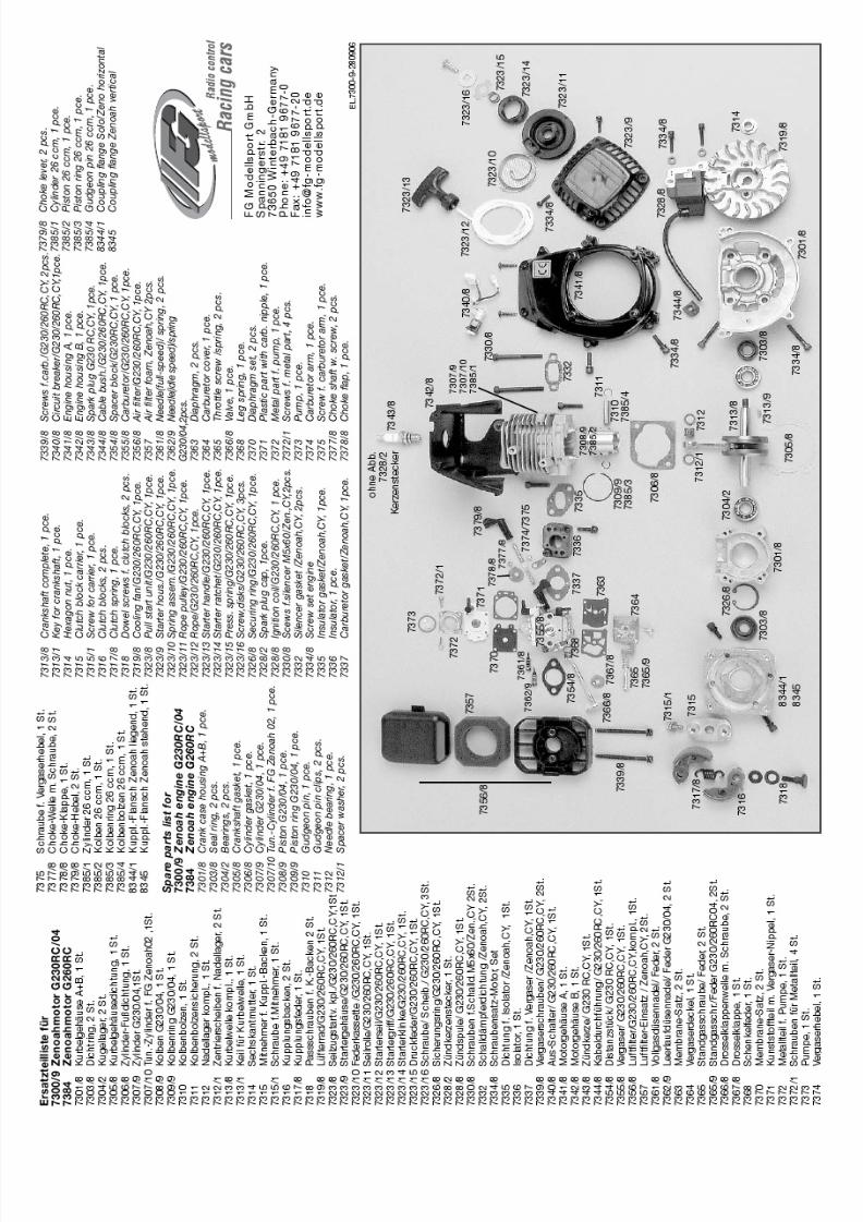
Warranty conditions for engines:
FG Modellsport assumes no liability for defects if the engine has been modified by installation of parts of foreign
origin or if engine parts for tuning purposes were worked on or were modified and the damage stands in causal
interrelationship with the modification. Further the liability for defects of power-increased engines is excluded. In
this case also the compensation liability is excluded.
8/7/2019 Léopard 2 - 4x2 -
http://slidepdf.com/reader/full/leopard-2-4x2- 3/24
Position 1Parts are inbag A+L
Position 2Parts are inbag B
1. Insert the diff. gearwheels in the alum. diff. housing as described in position 2. The insertingof the diff. gearwheels is much easier if you use the FG mounting tool Item N°. 08505.
2. Lubricate the ball diff. driving axles slightly with grease and press them into the alum. diffe-rential housing.
3. Mount the diff. bevel wheel axle. If the bevel gear axle respectively the driving axles can onlybe pushed in severely or if they cannot be pushed in at any position, then you have to dis-
mount the bevel gearwheels again and repeat the mounting.
1. Press M4x12 pan head screws from the bottomside into the alum. chassis and fix the ABS splash
guards le/ri using disks Ø4,3 and stop nuts M4.
2. Now press the body bolts from the inside intothe ABS splash guards le/ri and fix them with
some superglue, then clip on the body clips.
Aluminium bat-tery holder brace
Aluminiumchassis
ScrewM4x10
Screw4,2x16
Body mountadjustable
Screw2,9x9,5
ScrewM4x8
ScrewM3x8
O-ringØ6x3
Body clip
Body clip
Body bolt
ScrewM4x12
ABS splashguard
Alum. diff.bushing
CFRPchassisstiffening
Insert bush forchassis stiffening
The inserting of the diff. gearwheels or of the
complete package is much easier if you use the
FG mounting tool Item N°. 08505.
Disk Ø4,3
Stop nut M4
Disk Ø3,2
Alum.differentialhousing
O-rings
Steel gearwheel48 teeth
Ball diff.driving axle
Shim ring5x17x0,1
Diff. bevelwheelaxle
Shim ring8x20x0,1
Diff. gear-wheel A
Diff. gear-wheel B
All metric screws need to be secured with thread lock fluid.
4. If the gearwheels have toomuch clearance, correct it by
using the enclosed shim rings
5x17x0,1 und 8x20x0,1. Please
make sure that the gearwheel cle-
arance is not set too narrow.
5. Lubricate the gearwheels slightlywith some multipurpose grease, for
example Item N°. 06501.
6. Now press the parts as shownin position 2 on the alum. differen-
tial housing in the given sequen-
ce: O-ring large, o-ring small, steel
gearwheel 48 teeth, alum. diff.bushing. Fix the complete unit by
using M3x8 pan head screws and
disks Ø3,2. Mount the steel
gearwheel 48t. to the alum. diff.
housing using M4x8 countersunk
screws.
4. Mount the adjustable body mounts on the alum. chassis by using4,2x16 countersunk screws. Now fix 2,9x9,5 pan head screws into
the second boring from the top of the adjustable body mounts,
impress the o-ring and secure the alum. battery holder brace by
using body clips.
3. Impress the insert bushesfrom the top into the CFRP
chassis stiffening, then mount
it on the aluminium chassis
by using M4x10 countersunk
screws. Caution! Left and
right CFRP chassis stiffenings
differ, pay attention to the
borings.
8/7/2019 Léopard 2 - 4x2 -
http://slidepdf.com/reader/full/leopard-2-4x2- 4/24
Apply lubri-cating grease
Slightly lubricate theball driving shaft
Protection bellowBall diff. axle
Balldriving axle
Distancedisks
Balls fordriving shaft
Position 5Parts arein bag D
Position 3Parts are inbag B
Position 4Parts are inbag B
Alum. chassis
ScrewM4x20Disk Ø4,3
ScrewM5x14
ScrewM3x20
ScrewM5x14
Alum. adju-sting key 2°
Alum. wish-bone fixing2°, left
Guide bushwith collar
Guide bushwith collar
Rear loweralum. wish-bone
Alum.connectionbrace
Alum. rearaxle mountright
Alum. rearaxle mountleft
Headlesspin M5x20
Headlesspin M4x4
Headless pin M4x14
Impressguide bushes
W i s h b o n e p i n 6 x 8 5
Impressguide bushes
Stabilizer
5mm
Steel
ball
7mm
Balljoint7mm
SteelballØ7 x5mm Alum. retai-
ning collar5mm
Mounting of the ball driving shafts
Stick the distance disks into the round recess of the ball
driving axles as well as in the ball diff. axle using some
multipurpose grease. Mount the protection bellows to the
ball driving shafts according to the illustration. Slightly gre-
ase the ball area when mounting the protection bellow.
Apply some lubricating grease on the ball holes of the dri-
ving shafts and impress the balls. The balls will be held by
the lubricating grease and this way the driving shaft can bemounted more easily. Now push the complete ball driving
shaft into the differential axle and driving axle. Push the
protection bellows over the ball diff. axles and driving
axles.
1. Press the aluminium rear axlemounts left/right on the ball bea-
rings of the differential gear as
shown in position 3.2. Place the alum. rear axle mountsleft/right on the alum. chassis andfix them using M5x14 countersunkscrews.
3. Mount the alum. connectingbrace to the right alum. rear axle
mount using M4x20 pan head
screw and disk Ø4,3.
4. Impress the guide bushes withcollar into the alum. wishbone
fixings 2° left/right and mount them
with alum. adjusting key 2° and
M5x14 countersunk screws to the
rear axle mounts left/right.
Make sure the mounted wishbones can be moved easily up and down.
4. Screw the 7mm ball joints on the M4x14 headless pins until they are in contact anduntil they are 90° twisted. Impress a steel ball 7mm and steel ball Ø7x5mm each one
side of the ball joints 7mm.
5. Press the ball joints 7mm with the side of the steel ball Ø7x5mm on each side of the5mm stabilizer and fix them using the 5mm alum. retaining collar (collar facing the ball
joint) and the headless pin M4x4.
6. Mount the ball joints 7mm with the side of the steel ball 7mm to the rear lower alum.wishbones (with the collar of the steel ball facing backwards) using M3x20 pan head
screws. Impress the 5mm stabilizer into the alum. rear axle mounts.
Hint: To withdraw the rear lower wishbone pins 6x85mm screw an M4 screw into the taphole of the wishbone pins 6x85mm and pull them out.
1. Impress the guidebushes with collar
into the rear lower
alum. wishbones from
inside and outside.
2. Screw the headless pinM5x20 from the top centrally
into the rear lower alum. wish-
bones using screw retention.3. Fix the rear lower alum. wishbones withwishbone pins 6x85mm to the alum. wishbone
fixings 2° left/right, groove and thread must
face backwards.
8/7/2019 Léopard 2 - 4x2 -
http://slidepdf.com/reader/full/leopard-2-4x2- 5/24
All metric screws need to be secured
with thread lock fluid.
Rear loweralum. wish-bone
Headlesspin M4x4
1. Press the ball driving axles of the premounted ball driving set (posi-tion 5) into the alum. uprights equipped with ball bearings and fix the
alum. square wheel driver 9,5mm/M6 (shoulder facing the ball bearing)
on the areas of the ball driving axles (use high-strength screw reten-
tion).
2. Push the alum. uprights and wishbone pins 6x65mm into the rearlower alum. wishbones as shown in position 6.
3. Press each one adjusting clip front and rear between the alum.uprights and rear lower alum. wishbones on the wishbone pins, secure
the alum. uprights with M3x3 headless pins. Check the alum. uprights
on free movement.
4. Screw the ball joints 10mm M7 on the adjusting screws ri/leM7x102mm, impress alum. joint ball Ø10x13 and alum. ball retaining
collar Ø10x15 each one side of the ball joint 10mm M7, then screw the
2,9x13 pan head screws into the ball joints 10mm M7 and adjust the
ball clearance (position 7).
5. Mount the wishbone pins 6x63mm (with the side of the alum. ballretaining collar Ø10x15, collar in driving direction) through the pre-
mounted upper wishbones, now mount the alum. rear axle mounts ri/le
into the lower inside boring and secure them using Ø5 securing disks
and M4x4 headless pin.
6. Fix the premounted upper wishbones through the alum. joint ballØ10x13 (collar facing the alum. upright) using M5x25 pan head screws
to the alum. uprights le/ri.
Position 6Parts arein bag D
Alum. squarewheel driver9,5mm/M6 Balls for
drivingshaft
Adjustingclips
Adjusting clips
Securingdisk Ø5
Securingdisk Ø5
Wishbonepin 6x65
Wishbone pin 6x63
Ball dri-ving axle
Balldrivingshaft
Protection bellow
Distancedisk
Wheel nut
Headlesspin M6x6
Headlesspin M3x3
Alum. up-right left
ScrewM5x25
Screw2,9x13
Adjusting screwri/le M7 x 102
Ball joint10mm M7
Alum. ballretainingcollarØ10 x 15
Alum.jointballØ10x13
Ball diff.driving axle
Position 7Parts arein bag D
Use high-strengthscrew retention
Adjust rear upper w
ishbo-
nes to approx. 65
mm
8/7/2019 Léopard 2 - 4x2 -
http://slidepdf.com/reader/full/leopard-2-4x2- 6/24
Position 8Parts arein bag E
Position 8aParts arein bag E
O-ringØ22x1,5
Plastic bushØ5/Ø7x6,5
PlasticbushØ4,5/Ø7x4
Plastic guidingdisk
VolumecontrolØ20
Plastic damperpiston
Upper alum.shock absor-ber seal
Plasticadjustingring
Lower alum.shock absor-ber seal
Lower alum.shock absor-ber seal
Lower alum.shock absor-ber seal, pre-mountedGasket Ø4,5
Lower shockfastening,reinforced
Threadedpiston rod,short + long Threaded
piston rod,short + long
Pliers Item N°.06854
O-ringØ24x1,5
O-ringØ20x1,5
Position 8dParts arein bag E
Position 8c
Parts arein bag E
Position 8bParts arein bag E
Upper alum.shock absor-ber seal
DiskØ3,2
Stop nutM3
Lower alum.shock absor-ber seal, pre-mounted,short + long
Alum. shockabsorberhousingshort + long
Shock absor-ber oil 1000
Shock absorberlong, mounted
Shock absorbershort, mounted
Plastic adju-sting ring
Plasticadjustingring
Plastic springguide
Damperpressurespringorange2,4x40
Damper pres-sure springorange2,4x105
Damperpressurespring red2,4x105
Alum. springplate
1. Press plastic bush Ø5/Ø7x6,5 into the upper alum. shock absorber seals as shown in position 8 and insert the o-ring Ø22x1,5 in the groove.
2. Insert o-ring Ø24x1,5 in the groove of the plastic adjusting rings.
3. Mount the o-ring Ø20x1,5 into the groove of the lower alum. shock absorber seals.
4. Screw the lower reinforced shock fastenings on the thread of the threaded piston rods short and long until the thread can not be seen anymo-re. Make sure you do not damage the piston rod. Therefore we recommend to use the pliers Item N°. 06854.
5. Impress the plastic bushes Ø4,5/Ø7x4 and gaskets Ø4,5 into the lower alum. shock absorber seals, then press the volume control Ø20 on theplastic guiding disks and impress into the lower alum. shock absorber seals.
6. Push the threaded piston rods short and long carefully and with some shock absorber oil through the premounted alum. shock absorber sealsas shown in position 8b, then mount the plastic damper piston with disk Ø3,2 and stop nut M3. Do not tighten the stop nuts M3 too firm, make
sure the plastic damper pistons can still be moved.
7. Screw the plastic adjusting
rings with some oil on the alum.shock absorber housing short
and long as shown in position 8c.
8. Fix the assembled alum. shockabsorber seals with short piston
rod into the short shock absorber
housing.
Fix the assembled alum. shock
absorber seals with long piston
rod into the long shock absorber
housing.
9. Fill the shock absorbers withshock absorber oil up to the top
and move the piston rod carefully
several times in and out so that
the air bubbles in the oil come
upwards. As soon as no air bub-
bles appear anymore, pull the
piston rod completely out and
lock the shock absorbers with the
upper alum. shock absorber
seals.
10. Mount the orange damperpressure spring 2,4x40, the pla-
stic spring guide and red damper
pressure spring 2,4x10⁵ on the
long rear shock absorbers and
secure them with the alum. spring
plates as shown in position 8d.
Fix the orange damper pressurespring 2,4x10⁵ on the short front
shock absorbers and secure it
using the alum. spring plates.
8/7/2019 Léopard 2 - 4x2 -
http://slidepdf.com/reader/full/leopard-2-4x2- 7/24
All metric screws need to be secured with thread lock fluid.
Position 9Parts arein bag B,E+M
Position 10Parts arein bag H
ScrewM4x20
ScrewM5x25
ScrewM4x14
ScrewM5x10
Screw4,2x32
Mount forpull start
Rear shockabsorbermounted
Rearalum.damperplate
Rear CFRPdamper pro-tection
ScrewM4x18Disk Ø4,3
Disk Ø5,3Stop nutM5
Body clip
P l a s t i c b r a c e Ø 10 x 8 0
Adjusting partspoiler mount
Spoilermount
ScrewM5x40
Engine
Alum. engi-ne mountsmall
Stopnut M5
Stopnut M5
Headlesspin M5x20Screw for carrier
M6x14 with disk
Carrier forclutch shoes
Engine flan-ge for engi-ne quickfastening
1. Fix the rear alum. damper plateto the le/ri alum. rear axle mounts
using M4x18 pan head screws and
disks Ø4,3 ( Mount the cut-out of
the alum. shock mount in driving
direction).
2. Mount the rear assembled lowershock absorbers to the rear lower
alum. wishbones (medium threaded
hole) using M4x20 pan head
screws. Screw M5x25 pan head
screws in the outer threaded holes
of the alum. damper plate rear, thenfix the shock absorbers at the top
using disks Ø5,3 and stop nuts M5.
3. Mount the rear CFRP damperprotection to the le/ri alum. rear
axle mount using M4x18 pan head
screws and disks Ø4,3 on both
sides of the rear CFRP damper pro-
tection.
4. Fix the spoiler mount at the rearalum. damper plate using M4x14
cylinder head screws, mount the
plastic brace Ø10x80mm and the
adjusting parts spoiler mount in
between using 4,2x32 pan headscrews as shown in position 9. Clip
the body clips on the adjusting
parts spoiler mount.
5. Assemble the mount for the pullstart to the rear alum. damper plate
using M5x10 pan head screws as
shown in position 9.
1. Mount the small alum. engine mount to the engine usingM5x40 pan head screws and counter with M5 stop nuts.
For this purpose the original screws of the engine have to
be removed.
2. Apply screw retention lacquer on the four headless pinsM5x20 and screw them into the engine housing until they
poke out of the housing approx. 9mm.
3. Press the engine flange for the engine quick fastening(with the cutout facing the cylinder) on the housing or
respectively the headless pins and fix it using M5 stop nuts.4. Fix the carrier for the clutch shoes to the engine using anM6x14 hexagon screw with pressed on disk.
Hint: If the FG piston stop pin Item N°. 08542 is used, theassembling of the clutch shoe carrier will be considerably
simplified.
8/7/2019 Léopard 2 - 4x2 -
http://slidepdf.com/reader/full/leopard-2-4x2- 8/24
All metric screws need to be secured with thread lock fluid.
Position 11Parts arein bag H,J
Position 12Parts arein bag I
ScrewM5x16
Screw4,2x13
Screw4,2x13
Screw4,2x16
Engine
Manifold
Silencer gasket
O-ring for airfilter adapter
Air filteradapter
Filter cover
Foam filter
Basicbody
Clutchshoes
Clutchspring
Set screw forclutch shoes
Shaft washer
Drivin
g dire
ction
Disk6x15x1
ScrewM6x10
ScrewM5x14
ScrewM4x14
ScrewM4x14
ScrewM6x10
ScrewM6x16
ScrewM5x10
Steel gearwheel14 teeth
Headlesspin M5x5
Headlesspin M5x5
Headless pinM6x6
Tuning gear
shaft
Pre-filter forintake airfilter
longershaft flats
Steelgearwheel46 teeth
Set screw10x16x1
Alum.gearplate
Alum.gear flangeengine mount
Set screw10x16x1
Steelgearwheel18 teeth
Alum.gearwheeladapter
Tuningclutch bell
Engine flange forengine quickfastening
1. Clip the clutch spring inthe clutch shoes and push
the clutch shoes together
as pictured.
2. Place the shaft washerson the set screws for the
clutch shoes and push
them from the side with the
arrows (running direction of
the engine) into the clutch
shoes, then fix it on the
clutch shoe carrier using
6x15x1 disks.
Hint: If the FG piston stoppin Item N°. 08542 is used,
the assembling of the
clutch will be considerably
simplified.
3. Mount the manifold to the engine using M5x16 pan head screws and silencer gasket.
4. Insert o-ring for air filter adapter in the basic body and fix it to the air filter adapter using 4,2x13 countersunk screws.5. Press the oiled foam filter on the basic body and fix it with the filter cover and a 4,2x16 countersunk screw.
Hint: The enclosed foam filter is ready-to-use and oiled. If at a later point of time a filter is required which is ready-to-use, please proceed as fol-lows: in order to oil the foam filter place the filter together with some FG filter oil for foam filter Item N°. 06441 in a plastic bag and press together
to rub it in.
1. Pull the pre-filter for the intake air fil-ter over the completely mounted air fil-
ter, pull it together with the lace and fix
it with a tie.
2. Impress the tuning clutch bell withtwo set screws 10x16x1 in the alum.
gear plate as shown in position 12,
now mount set screw 10x16x1 and
steel gearwheel 18 teeth on the flats ofthe tuning clutch bell using M5x5
headless pins, secure with M6x10 pan
head screw.
3. Assemble the alum. gear plate at thealum. gear flange-engine mount using
M4x14 cylinder head screws. Screw
M5x14 pan head screw into the alum.
gear flange-engine mount, but do not
tighten yet.
4. Press the tuning gear shaft at theside with the longer shaft flats flush
into the alum. gearwheel adapter and
secure with M6x6 headless pins and
M6x10 pan head screws.5. Mount steel gearwheel 46 teeth tothe alum. gearwheel adapter using
M5x10 pan head screws.
6. Press the tuning gear shaft throughthe ball bearings of the alum. gear
plate and alum. gear flange-engine
mount.
7. Press the steel gearwheel 14 teethon the tuning gear shaft as shown in
position 12 and fix it using M5x5 head-
less pins on the flats of the tuning gear
shaft, secure with M6x16 countersunk
screw. Use high-strength screw reten-
tion.8. Plug the complete gear unit on theengine flange for engine quick faste-
ning.
8/7/2019 Léopard 2 - 4x2 -
http://slidepdf.com/reader/full/leopard-2-4x2- 9/24
Position 13Parts arein bag H+K
Position 14Parts arein bag I
ScrewM5x14
Alum. gear flange-engine mount
Please pay attention that drive gearwheels, drive shafts a.s.o. can be moved easily and without any resistance.
1. Tighten the M4x25 pan head screw aftertightening the engine fixing screws.
2. Tighten the M5x14 pan head screw at thealum. gear flange-engine mount.
ScrewM4x25DiskØ4,3
ScrewM4x25Disk Ø4,3
ScrewM4x14
ScrewM4x8
ScrewM4x8
Alum. ch
assis
Tank complete
Engine fixingdisk
Alum. rearaxle mountleft
Alum. connec-ting brace
1. Insert the premounted enginein the alum. chassis as illustra-
ted in position 13 and fix it
using an M4x25 pan head
screw and disk Ø4,3 through
the left alum. rear axle mount,
also fix it with the alum. connec-
ting brace at the alum. gear
flange-engine mount. Just apply
the M4x25 pan head screw, do
not tighten yet (see also position
14).
2. Mount the pre-assembledengine in the alum. chassis
using M4x14 countersunk
screws and engine fixing disks.
3. Fix the tank in the alum.chassis using M4x8 counter-
sunk screws as shown in posi-
tion 13.
8/7/2019 Léopard 2 - 4x2 -
http://slidepdf.com/reader/full/leopard-2-4x2- 10/24
All metric screws need to be secured with thread lock fluid.
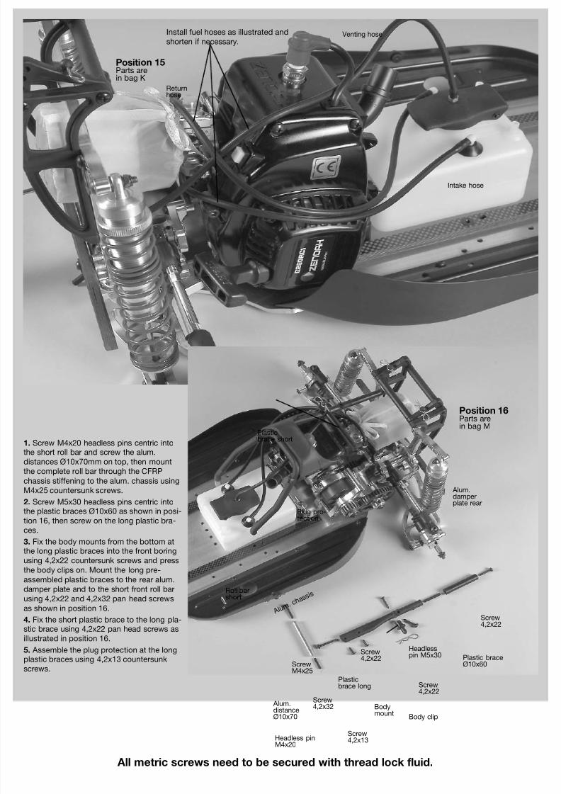
Install fuel hoses as illustrated and
shorten if necessary.
Position 15Parts arein bag K
Position 16
Parts arein bag M
Returnhose
Intake hose
Venting hose
Screw4,2x22
Screw4,2x22
Screw4,2x22
ScrewM4x25
Screw4,2x13
Screw4,2x32
Plug pro-tection
Plasticbrace long
Plasticbrace short
Alum.distanceØ10x70
Plastic braceØ10x60
Bodymount
Roll barshort
Headlesspin M5x30
Headless pinM4x20
Alum.damperplate rear
Body clip
Alum. c
hassi
s
1. Screw M4x20 headless pins centric intothe short roll bar and screw the alum.
distances Ø10x70mm on top, then mount
the complete roll bar through the CFRP
chassis stiffening to the alum. chassis using
M4x25 countersunk screws.
2. Screw M5x30 headless pins centric intothe plastic braces Ø10x60 as shown in posi-
tion 16, then screw on the long plastic bra-
ces.
3. Fix the body mounts from the bottom atthe long plastic braces into the front boring
using 4,2x22 countersunk screws and press
the body clips on. Mount the long pre-
assembled plastic braces to the rear alum.
damper plate and to the short front roll bar
using 4,2x22 and 4,2x32 pan head screws
as shown in position 16.
4. Fix the short plastic brace to the long pla-stic brace using 4,2x22 pan head screws as
illustrated in position 16.
5. Assemble the plug protection at the longplastic braces using 4,2x13 countersunk
screws.
8/7/2019 Léopard 2 - 4x2 -
http://slidepdf.com/reader/full/leopard-2-4x2- 11/24
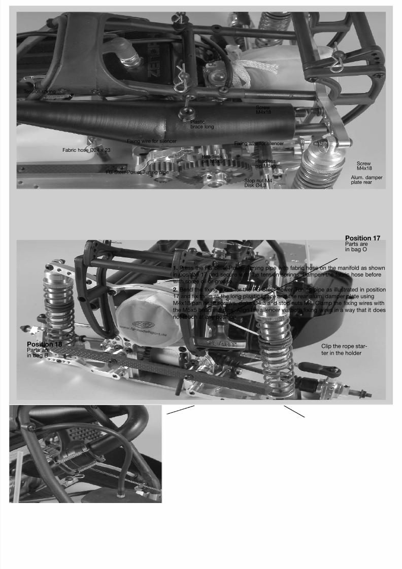
Position 17Parts arein bag O
Position 18Parts arein bag B
Fixing wire for silencerFixing wire for silencer
Fabric hose Ø24 x 23
Tension spring
FG Steel-Power Tuning pipe
Plasticbrace long
Alum. damperplate rear
Clip the rope star-
ter in the holder
ScrewM4x18
ScrewM4x18
Stop nut M4Disk Ø4,3
Headlesspin M5x5 Headless
pin M5x5
1. Press the FG Steel-Power Tuning pipe with fabric hose on the manifold as shownin position 17 and secure with the tension springs. Dampen the fabric hose before
with some oil or grease.
2. Bend the fixing wires for the FG Steel-Power Tuning pipe as illustrated in position
17 and fix them at the long plastic brace and the rear alum. damper plate usingM4x18 pan head screws, disks Ø4,3 and stop nuts M4. Clamp the fixing wires with
the M5x5 headless pins. Align the silencer via both fixing wires in a way that it does
not touch at any position.
8/7/2019 Léopard 2 - 4x2 -
http://slidepdf.com/reader/full/leopard-2-4x2- 12/24
All metric screws need to be secured with thread lock fluid.
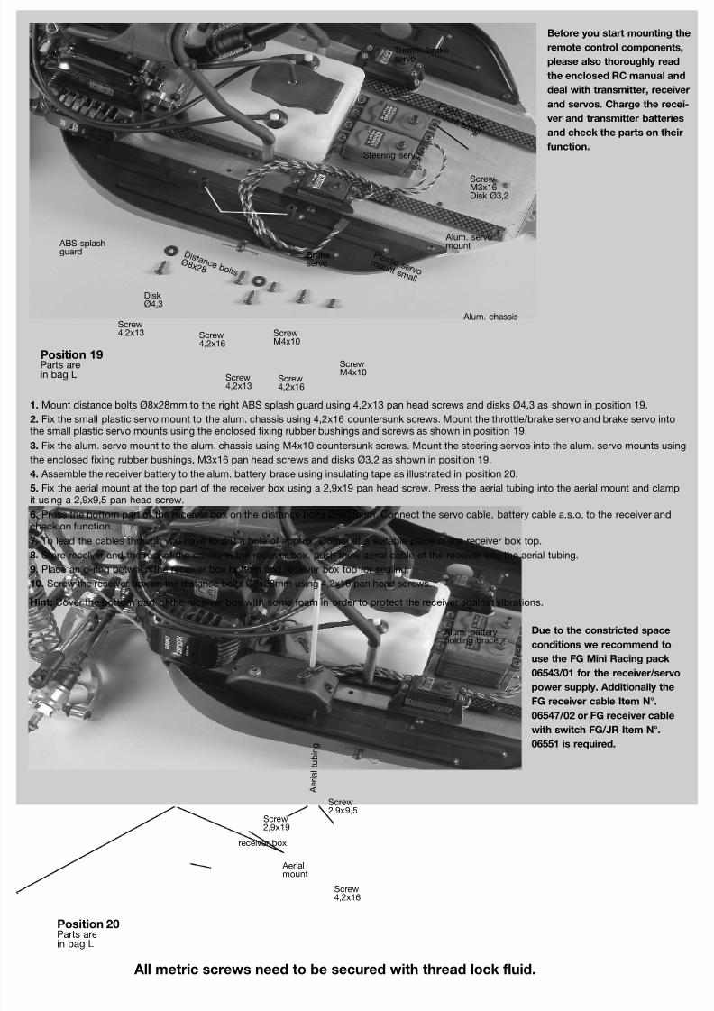
Position 19Parts arein bag L
Position 20Parts arein bag L
ScrewM3x16Disk Ø3,2
D i s t a n c e b o l t s
Ø 8 x 2 8
Before you start mounting the
remote control components,
please also thoroughly read
the enclosed RC manual and
deal with transmitter, receiver
and servos. Charge the recei-
ver and transmitter batteries
and check the parts on their
function.
Alum. servomount
Screw4,2x13
Screw4,2x13
Screw4,2x16
Screw4,2x16
Screw4,2x16
ScrewM4x10
ScrewM4x10
DiskØ4,3
P l a s t i c s e r v o m o u n t s m a l l
Brakeservo
Steering servo
Throttle/brakeservo
P l a s t i c s e r v o m o u n t s m a l l
Screw2,9x9,5
Screw2,9x19
Ae ria l tub i ng
Aerialmount
receiver box
Alum. chassis
1. Mount distance bolts Ø8x28mm to the right ABS splash guard using 4,2x13 pan head screws and disks Ø4,3 as shown in position 19.
2. Fix the small plastic servo mount to the alum. chassis using 4,2x16 countersunk screws. Mount the throttle/brake servo and brake servo intothe small plastic servo mounts using the enclosed fixing rubber bushings and screws as shown in position 19.
3. Fix the alum. servo mount to the alum. chassis using M4x10 countersunk screws. Mount the steering servos into the alum. servo mounts using
the enclosed fixing rubber bushings, M3x16 pan head screws and disks Ø3,2 as shown in position 19.
4. Assemble the receiver battery to the alum. battery brace using insulating tape as illustrated in position 20.
5. Fix the aerial mount at the top part of the receiver box using a 2,9x19 pan head screw. Press the aerial tubing into the aerial mount and clampit using a 2,9x9,5 pan head screw.
6. Press the bottom part of the receiver box on the distance bolts Ø8x28mm. Connect the servo cable, battery cable a.s.o. to the receiver and
check on function.7. To lead the cables through you have to drill a hole of approx. Ø8mm at a suitable place of the receiver box top.
8. Store receiver and the rest of the cables in the receiver box, push thew aerial cable of the receiver into the aerial tubing.
9. Place an o-ring between the receiver box bottom and receiver box top for sealing.
10. Screw the receiver box on the distance bolts Ø8x28mm using 4,2x16 pan head screws.
Hint: Cover the bottom part of the receiver box with some foam in order to protect the receiver against vibrations.
ABS splashguard
Alum. batteryholding brace
Due to the constricted space
conditions we recommend to
use the FG Mini Racing pack
06543/01 for the receiver/servo
power supply. Additionally the
FG receiver cable Item N°.
06547/02 or FG receiver cable
with switch FG/JR Item N°.
06551 is required.
8/7/2019 Léopard 2 - 4x2 -
http://slidepdf.com/reader/full/leopard-2-4x2- 13/24
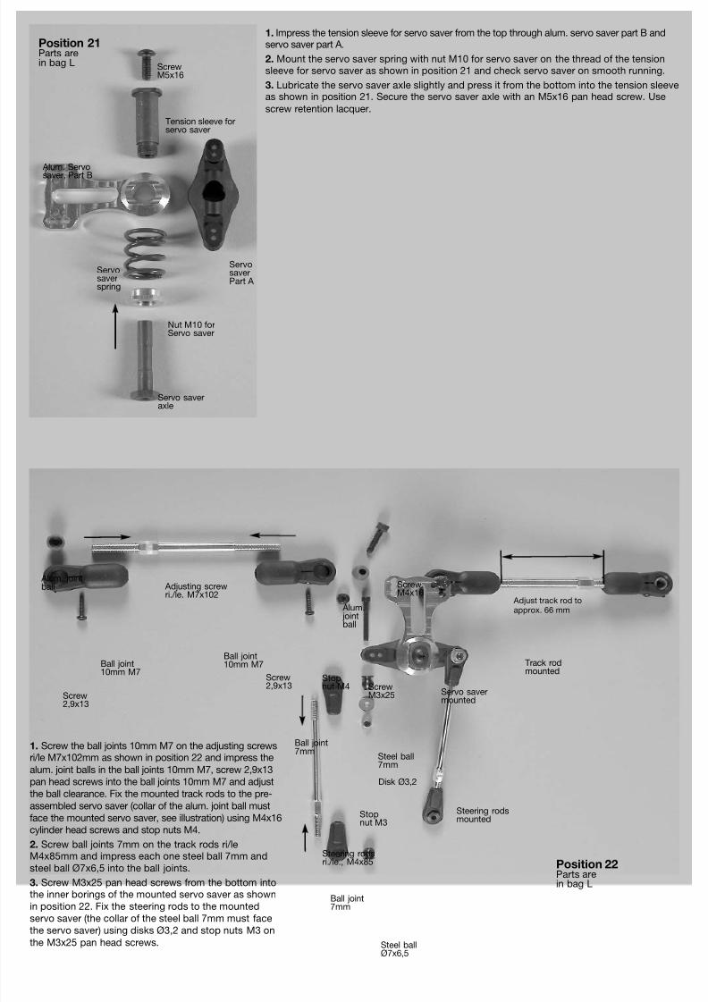
Position 21Parts arein bag L
Position 22
Parts arein bag L
Disk Ø3,2
1. Screw the ball joints 10mm M7 on the adjusting screwsri/le M7x102mm as shown in position 22 and impress the
alum. joint balls in the ball joints 10mm M7, screw 2,9x13
pan head screws into the ball joints 10mm M7 and adjust
the ball clearance. Fix the mounted track rods to the pre-
assembled servo saver (collar of the alum. joint ball must
face the mounted servo saver, see illustration) using M4x16
cylinder head screws and stop nuts M4.
2. Screw ball joints 7mm on the track rods ri/leM4x85mm and impress each one steel ball 7mm and
steel ball Ø7x6,5 into the ball joints.
3. Screw M3x25 pan head screws from the bottom intothe inner borings of the mounted servo saver as shown
in position 22. Fix the steering rods to the mounted
servo saver (the collar of the steel ball 7mm must face
the servo saver) using disks Ø3,2 and stop nuts M3 on
the M3x25 pan head screws.
Servo saveraxle
Tension sleeve forservo saver
Alum. Servo
saver, Part B
ServosaverPart A
Servosaverspring
Nut M10 forServo saver
ScrewM5x16
Alum. jointball
Alum.jointball
Ball joint7mm
Ball joint7mm
Steering rodsri./le., M4x85
Steel ballØ7x6,5
Adjusting screwri./le. M7x102
Steel ball7mm
Steering rodsmounted
Track rodmounted
Servo saver
mounted
ScrewM4x16
ScrewM3x25Screw
2,9x13
Screw2,9x13
Stopnut M4
Stopnut M3
Ball joint10mm M7
Ball joint10mm M7
1. Impress the tension sleeve for servo saver from the top through alum. servo saver part B andservo saver part A.
2. Mount the servo saver spring with nut M10 for servo saver on the thread of the tensionsleeve for servo saver as shown in position 21 and check servo saver on smooth running.
3. Lubricate the servo saver axle slightly and press it from the bottom into the tension sleeveas shown in position 21. Secure the servo saver axle with an M5x16 pan head screw. Use
screw retention lacquer.
Adjust track rod toapprox. 66 mm
8/7/2019 Léopard 2 - 4x2 -
http://slidepdf.com/reader/full/leopard-2-4x2- 14/24
All metric screws need to be secured with thread lock fluid.
Position 23Parts arein bag L
Position 24Parts arein bag L
2. Switch on the remote control system, set the trimming ofthe steering to central position.
3. First mount an assembled steering rod (collar of the ballmust face towards the servo arm) to the servo arm using
M3x18 pan head screw, disk Ø3,2 and stop nut M3 as
shown in position 24. Press the servo arm on the toothing of
the steering servo as illustrated in position 24 and fix it with
enclosed screw. The servo arm should be mounted in 90°
position to the steering servo, it may be necessary to shor-
ten it depending on the version. Now fix the second assem-
bled steering rod to the second servo arm in the same way,
both steering rods must have the identical length, make
sure you are able to press the servo arm easily and without
any resistance on the toothing of the steering servo.
ScrewM5x25
Alum distancefor servosaver
Alum. chassis
StopnutM3
Servo arm
ScrewM3x18Disk Ø3,2
Steering rodsmounted
Servo savermounted
1. Mount the pre-assembled servo saveron the alum. chassis using M5x25 coun-
tersunk screw and alum. distance as
shown in position 23.
8/7/2019 Léopard 2 - 4x2 -
http://slidepdf.com/reader/full/leopard-2-4x2- 15/24
Position 25Parts arein bag F
Position 26Parts arein bag G
Alum. chassis
ScrewM4x14
ScrewM4x14Screw
M4x8
ScrewM4x10
ScrewM4x14
ScrewM5x14
ScrewM5x14
ScrewM4x10
ScrewM4x10
Screw4,2x16
ScrewM4x16
ScrewM3x18
ScrewM3x6
Headlesspin M5x20
Headlesspin M3x3
Headlesspin M5x10
Alum. frontaxle support
Wishbone
pin 6x8
8
Alum.springdeflectionstop
Alum. front
axle mount A
Alum. frontaxle mount A
Alum. frontaxle mount B
Alum. frontaxle mount B
Alum. frontaxle mount C
Alum. dam-per platefront
Reinforcingplate forfront axle
Body mount adjusta-ble 54mm,support for bodymount,body clip
Fix the
mount forstabilizer4mm part Bon the left
Collet4mm
Steel ball Ø7x5mm, Ø4
Stabilizer 4mmfront
Ballbush
Front loweralum. wishbone
Guide bushwith collar
Adjusting clipsSecuringdisk Ø5
Headlesspin M4x14
Steel
ball
7mm
Ball joint7mm
1. Place the alum. front axlemounts A, B and C on the alum.
chassis and fasten them using
M4x14 countersunk screws as
pictured in position 25.
2. Mount the alum. springdeflection stops to the alum.
front axle mount A using M4x8
pan head screws as shown in
position 25.
3. Mount the alum. front axlesupport to the alum. front axle
mount B using M4x10 pan head
screws and to the alum. chassis
using M4x14 countersunk
screws as illustrated in position
25.
4. Secure the impressed ballbushes in the front lower alum.
wishbones with M3x6 pan head
screws.
5. Press the guide bushes withcollar into the front lower alum.
wishbones.
6. Screw the M5x20 headlesspins centric from below and the
M5x10 headless pins centric
from the top into the front lower
alum. wishbones as shown in
position 25 (use screw reten-
tion).
7. Place the front lower alum. wishbones between the alum. front axlemounts A + C as shown in position 25. Impress the wishbone pins
6x88mm in the alum. front axle mounts A + C (threaded hole must face
forwards) and through the pre-assembled front lower alum. wishbones,
secure with Ø5 securing disks. Press each two adjusting clips on the
wishbone pins 6x88mm between front lower alum. wishbone and alum.
front axle mount C. Make sure the wishbones can be moved easily up
and down.Hint: To remove the front lower wishbone pins 6x88mm screw an M4screw into the threaded hole of the wishbone pin 6x88mm and pull it out.
1. Mount the front alum. damperplate to the reinforcing plate for the
front axle using M5x14 pan head
screws as shwon in position 26.
2. Fix the support for body mountto the adjustable body mount
54mm as pictured in position 26
and fasten it at the reinforcing plate
for front axle using an 4,2x16 coun-
tersunk screw.
3. Fasten the assembled reinforcingplate on the alum. front axle
mounts A + B using M4x10 pan
head screws.
4. Screw ball joints 7mm on theM4x14 headless pins until they are
in contact and 90° distorted.
Impress each one steel ball 7mm
and steel ball Ø7x5mm, Ø4 in one
side of the ball joints 7mm.
5. Press the ball joint 7mm (steelball side Ø7x5mm, Ø4) on each one
end of the front stabilizer 4mm and
fasten with collet 4mm and head-
less pin M3x3.
6. Mount the ball joint 7mm (steel ball side 7mm) to the front lower alum. wishbones (collar of thesteel ball must face forwards) using M3x18 pan head screws.
7. Press the mount for stabilizer 4mm part A + B into the front stabilizer 4mm as shown in position26, impress in alum. front axle mount A, then fix with M4x16 pan head screws.
8/7/2019 Léopard 2 - 4x2 -
http://slidepdf.com/reader/full/leopard-2-4x2- 16/24
Screw M4x12
ScrewM4x12
ScrewM4x14
Screw4,2x22
Screw4,2x22
Alum. steeringlever
Alum. stee-ring lever
Plastric stee-ring stopshortened
Plastic stee-ring stopshortened
Front leftalum. uprights
Front alum.uprights
Front rightalum. uprights
Ball bearing15x28x7
Ball bearing17x26x7
1. Mount the alum. steering laver to the front alum.uprights right/left using M4x12 cylinder head screws
as shown in position 27.
2. Fix the plastic steering stop shortened to the alum.steering lever using 4,2x22 pan head screws.
Tipp: The front alum. uprights on the right and leftside are the same, but according to the position of
alum. steering lever and plastic steering stops they
have to be built differently.
All metric screws need to be secured with thread lock fluid.
Position 27Parts arein bag F
Position 28Parts arein bag F
Front lower
alum. wishbone
Securingdisk Ø5
Securingdisk Ø5
Alum. bearingadapter for frontdriving axle
Driving axle57mm front
Adjustingclips
Guide bushwith collar
Headlesspin M6x6
Front upperalum. wish-bone
Wishbonethread rodM10/M8x108
Wishbone
pin 6x6
0
DiskØ5,3
DiskØ5,3
ScrewM5x25
ScrewM5x25
Hexagonnut M10LH thread
Wheel nut
Ball jointfor M8
Alum.joint ball
Ø5/10x15mm
Taperdisk
Alum. square
wheel driver9,5mm/M6
1. Press the guide bushes withcollar into the front upper alum.
wishbones.
2. Screw the hexagon nuts M10LH thread on the wishbone track
rods M10/M8x108mm and turnthem into the front upper alum.
wishbones, then screw ball joints
for M8 on the wishbone track
rods M10/M8x108mm and
impress aluminium joint ball
Ø5/10x15mm in the ball joints for
M8.
3. Press the wishbone pins6x60mm through the pre-assem-
bled front upper alum. wishbones
into the alum. front axle mounts
A + B and secure with Ø5 secu-
ring disks.
4. Press each four adjusting clipsin the front between alum. front
axle mount A and front upper
alum. wishbones on the wishbo-
ne pins 6x60mm.
5. Press Ø5 securing disks intothe groove of the front driving
axles 57mm and impress them
with the alum. bearing adapter
for front driving axle into the pre-
assembled alum. uprights le/ri as
shown in position 28. Mount
alum. square wheel driver
9,5mm/M6 (offset facing the bea-
ring) with M6x6 headless pins on
the flats of the front driving axles57mm. Use high-strength screw
retention.
6. Fix the le/ri alum. uprights tothe lower alum. wishbones with
two disks Ø5,3 between taper
disk and alum. uprights by using
M5x25 countersunk screws.
7. Mount the alum. le/ri uprightsto the assembled upper alum.
wishbones with a disk Ø5,3 bet-
ween alum. joint ball
Ø5/10x15mm and alum. uprights
using M5x25 pan head screws.
8. Mount the track rods (collar ofthe alum. joint ball must face the
alum. steering lever) into the
second thread hole from the top
using M4x14 cylinder head
screws. Hint: Always mount the taper disks with the thinner side facing the ball bush.
Alum. frontaxle mount A
Alum. frontaxle mount B
T r a c k r o d
8/7/2019 Léopard 2 - 4x2 -
http://slidepdf.com/reader/full/leopard-2-4x2- 17/24
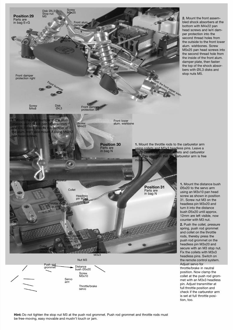
Position 29Parts arein bag E+G
Position 30Parts arein bag N
Position 31Parts arein bag N
1. Mount the front bumper to the alum.chassis using M4x8 pan head screws
and Ø4,3 disks, also fix the bumper at
the alum. front axle mount A using M4x12
pan head screws.
Front loweralum. wishbone
ScrewM4x12
ScrewM4x8
ScrewM4x22
Front damperprotection left
Front damperprotection right
Alum. frontaxle mount A
F r o n t b u m p e r
DiskØ4,3
ScrewM5x25
Disk Ø5,3Stop nutM5
Front alum.damperplate
Throttle rods
Collet
Headlesspin M3x3
Carburetorarm
Servoarm
Nut M3
Throttle/brake
servo
Throttle rods
ColletHeadless pinM3x3
ColletHeadless pinM3x3
Druckfed
er
Push rodgrommet
GewindestiftM3x20 Stopp-Mutter M3
Distancebush Ø5x20
ScrewM3x10
A d j u s t t h e f r o n t u p p e r w i s h -
b o n e t o a p p r o x . 6 0 m m
2. Mount the front assem-bled shock absorbers at the
bottom with M4x22 pan
head screws and le/ri dam-
per protection into the
second thread holes from
the outside to the front lower
alum. wishbones. Screw
M5x25 pan head screws into
the second thread hole from
the inside of the front alum.damper plate, then fasten
the top of the shock absor-
bers with Ø5,3 disks and
stop nuts M5.
1. Mount the throttle rods to the carburetor armusing collets and M3x3 headless pins. Leave a
slight clearance between collets and carburetor
arm. Pay attention that the carburetor arm is free
movable.
1. Mount the distance bushØ5x20 to the servo arm
using an M3x10 pan head
screw as shown in position
31. Screw nut M3 on the
headless pin M3x20 and
turn it into the distance
bush Ø5x20 until approx.
12mm are left visible, now
counter with M3 nut.
2. Push the collet, pressurespring, push rod grommet
and collet on the throttlerods, thereby press the
push rod grommet on the
headless pin M3x20 and
secure with an M3 stop nut.
Fix the collets with M3x3
headless pins. Switch on
the remote control system.
Adjust servo for
throttle/brake in neutral
position. Now clamp the
collet at the push rod grom-
met with an M3x3 headless
pin. Adjust transmitter at
full throttle position andcheck if the carburetor arm
is set at full throttle posi-
tion, too.
Hint: Do not tighten the stop nut M3 at the push rod grommet. Push rod grommet and throttle rods mustbe free-moving, easy movable and mustn’t touch or jam.
8/7/2019 Léopard 2 - 4x2 -
http://slidepdf.com/reader/full/leopard-2-4x2- 18/24
Position 32Parts are inbag Q
Position 33Parts are inbag Q
Front disk brake
Front disk brake
The brake tube at the front respectively therear axle must not be squeezed or pulled bychassis components during deflecting orsteering.
All metric screws need to be secured with screw retention lacquer, pay attention to enclosed brake manual.
1. Mount each one angle connection and one valve each main brake cylinder as described in position 33 and 35. Do not tighten the valves too
firm, otherwise the valve seat might be damaged.2. Mount the main brake cylinder on the chassis plate for the front wheels (right driving direction) respectively the rear wheels (left driving direc-tion) as shown in position 33 and 35.
3. Place the brake disks on the square wheel drivers, then fasten the brake calipers at the uprights using M3x30 screws. Now mount the angleconnections and the valves as described in position 32 and 34.
4. Arrange the brake tubes as illustrated. Pay attention to the following when you mount the brake tube: Shorten the brake tube only with a sharpknife or the FG cutting knife Item N°. 09449! Please make sure that the brake tubes to front respectively rear axle are long enough and allow the
full steering angle (frant axle) respectively spring defection. Press the brake tubes completely into the T-pieces respectively angle connections.
Don’t lay the brake tubes too close at hot vehicle components as exhaust manifold or silencer.
Brake disk
Cable clip
Protective hose
Brake caliper
ScrewM3x30
Brake tube
Angle connection
Proctection cap
T-piece
Main brakecylinder
Pressurespring Push rod
grommet
Collet
Collet
Br ak e r ods
Brake servoServoarm
ScrewM3x18
Stopnut M3
Brake tube to thefront wheels
Angleconnection
8/7/2019 Léopard 2 - 4x2 -
http://slidepdf.com/reader/full/leopard-2-4x2- 19/24
5. Install the brake rods with pressurespring and collets as described in posi-
tion 33 and 35. Left side in driving
direction for the rear axle, right side for
the front axle. According to the moun-
ting height and the size of the servosthe brake rods need to be bent slightly
towards the main brake cylinder. Bend
the brake rods according to the cir-
cumstances. Nevertheless it should run
smoothly and should not touch
anywhere.
6. Fill and bleed the brake system. Forfilling and bleeding please refer to the
enclosed brake manual.
7. Place rubber protective caps on thevalves.
8. Impress securing rings into the angleconnections and T-pieces.
The brake tube at the front respectively the rear ax-le must not be squeezed or pulled by chassis com-ponents during deflecting or steering.
Position 35Parts are inbag Q
Position 34Parts are inBag Q
Rear disk brake
Rear disk brake
Cable clip
Protective hose
Brake disk
Brake caliper
ScrewM3x30
Brake tube
Protectioncap
Angleconnection
T-piece
Main brakecylinder
Pressurespring
Push rodgrommet
Collet
Collet
Brake
rodsServoarm
ScrewM3x18
Stopnut M3
Angle con-nection
Brake tube tothe rear wheels
Throttle/brake servo
8/7/2019 Léopard 2 - 4x2 -
http://slidepdf.com/reader/full/leopard-2-4x2- 20/24
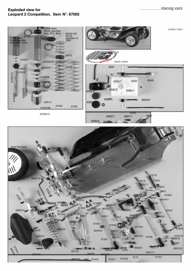
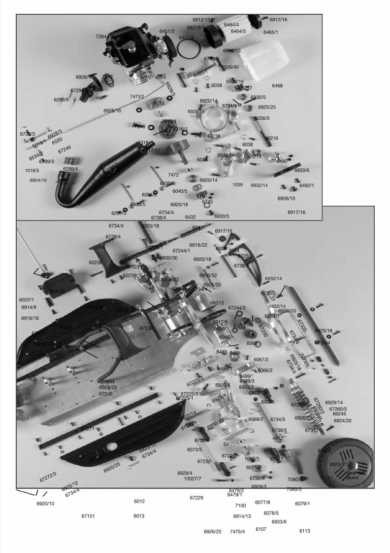
Exploded view forLeopard 2 Competition, Item N°. 67005
8381
8381
8381
8381/1
8380/1
8380/4
8380/8
8380/8
8380/3
8380/7
8380/6
6920/8
6732/46350/1 6350 6349
6350
8381/1
8381/3
E.67005-170910
6912/16
6912/16
6920/10
6920/14
6920/14
6920/14
6924/18
6930/20
6930/10
1097/11097/16929/14
67260/5
67271
60100/2
67165
67160
67320/01
67330/1
67320/3
67320/5
67315
67320/11
67320/14
67320/15
6734/3
67320/12
6481/467320/4
67320/7
67320/9
67320/8
67320/10
67330/2
673
20/02
67320/066730267303
67312
67302
67336
8514/8
67260/1
6726
8
67256
67266
67267
6029/8
6926/25
7475/1
6 7 2 8 7
6 7 2 8 7
6260/1
6 7 2 6 1
6 7 2 8 5 67257
67258
7155
6725
9
6726
9
6 7 2 6 5
67286
6 7 2 4 3
7154/2
67242
6924/25
6924/18
6924/16
6922/25
68423/1
67239/1
6013
4493/3
6932/14
6932/16
6738/4
6734/5
6734/3
67240
69241
6926/25
6926/14
6738/56734/5
6928/3
6738/3
6738/3
6914/9
6914/13
6925/22
6925/10
6925/10
6925/16
6925/8
67229
10027/7
7475/26113
Front tire glued
66245
6732/56732/5
6104/1
67264
66270/4
6933/66107
7100
7100
66244/1
66244/1
66245
1213/10
6926/16
68326
68325/1
68323
68324/1
68327/1
6078/5
66270/1
66270/2
66271
6 9 3 2 / 12
6916/22
66226/2
6922/25
4429/2
6734/54466
6917/6
60230
6 7 3 4 / 4
6 9 2 5 / 8
6925/12
6738/3
67320/13
66295/100Shockabsorber oil1000
67320 Alum.Shock absorberlong, Ø24, 2pcs.
67330 Alum.shock absorbershort, Ø24, 2pcs.
8/7/2019 Léopard 2 - 4x2 -
http://slidepdf.com/reader/full/leopard-2-4x2- 21/24
7384
66218/16464/4
6464/5 6465/1
6912/13
6912/13
6912/16
6451/4
6451/3
6468
7473/2
1039
6738/5
6485/1
6038
6038
6038
6920/14
6920/14
6920/14
66217
6923/16
6930/5
6734/4 6925/25
66216
6490
6492/1
6926/10
6926/10
6917/16
6926/40
6917/16
6 9 2 9 / 4
6929
/4
6929/4
6929/14
6924/20
6930
/20
1097
/1
1097/1
67225/167225/2
6722
5/3
67226
6722
7
7 0 7 1 / 1
6 7 2 6 0 / 2
67260/467260/5
6 7 2 3 0
6204/16 7 3 3 5
6925/18
6 9 2 5 / 1 8
6926/25
6926/25
67303
67312
6922/14
6922
/14
67235
67236
Rear tireglued
67271
67250
6917/8
6065
8486/1
6048
67251
6038 3024
6738/4
672456929/20
67244
67151
67151
6916/16
6916/13
67247
67244/1
5 0 1 4
/ 5 6013
6013
6012
6912/22
6916/32
6036/5
6932/14
6932/14
6932/14
6932/14
6926/14
67238
6930/5
7315
7315/1
7316/1
7472
6040/5
6745
6745
6432
7317/11
7318
7318
6926/16
6926/16
6299/5
6729
8/1
67298/2
6299/4
7332
6291/3
6738/4
6738/5
6738/4
6930/5
6930/5
6734/4
6734/4
6734
/4
6734
/4
6 7 3 4 / 4
6 7 3 4 / 4
6734/5
6734/4
6734/4
6925/18
6925/18
6291/3
60206 9 2 8 / 3
6724
660
2069
28/36738/3
6739/3
5019
/1
6534
/2
1018/5
6924/10
6933/6
6912/13
6930/30
6916/22
6916/22
60238
60239
60239/1
6914/9
6914/19
6914/13
6022/1
66241
66212
6925/20
6925/20
6920/10
6727
2/3
6727
0/3
6727
0/2
6925/12
6925
/12
6920
/25
7475/4
67232
67229
10027/7
8493/56920/8
84958489
6066/2
6067/2
6068
8499/18499/3
6113
6079/1
4412
7080/2
7080/3
67277
6069/266245
6075/5
6073/5
6732/5
6732/5
6933/6
6107
6077/8
6078/5
6479/16479/2
6928/3
7100
6920/18
6916/32
67244/2
8/7/2019 Léopard 2 - 4x2 -
http://slidepdf.com/reader/full/leopard-2-4x2- 22/24
8/7/2019 Léopard 2 - 4x2 -
http://slidepdf.com/reader/full/leopard-2-4x2- 23/24

8/7/2019 Léopard 2 - 4x2 -
http://slidepdf.com/reader/full/leopard-2-4x2- 24/24