Embed Size (px)
Citation preview
NDE Methods for Certification and Production/Performance Monitoring of
Composite Tanks
NDE Methods for Certification and Production/Performance
Monitoring of Composite Tanks
David McColskey, Marvin Hamstad NIST-Boulder, CO
Regor Saulsberry, Jess Waller
NASA-JSC White Sands Test Facility
Nondestructive Evaluation and Monitoring Results from COPV
Accelerated Stress Rupture Testing
NASA WSTF: Regor Saulsberry
NASA WSTF: Nathanael Greene
NASA LaRC: Eric Madaras
NASA JSC: Scott Forth
NASA MSFC: Curtis Banks
NASA/KSC: Richard Russell
Cornell University: Leigh Phoenix
Use of Modal Acoustic Emission to Monitor Damage Progression
in Carbon Fiber/Epoxy Tows and Implications for Composite
Structures
Jess M. Waller, Regor L. Saulsberry
NASA-JSC White Sands Test Facility
Charles T. Nichols, Intern, New Mexico State Univ., Dept.
Mech. and Aerospace Engineering
Daniel J. Wentzel, Intern, Miami University, Department of
Physics
Applications of Acoustic Emission to Composite Pressure Vessels – Manufacturing Certification and Correlations with the Residual Strength Loss Due to
Impact Damage
M.A. Hamstad
NIST Boulder
and University of Denver

3
Background
Problems:
• COPVs can be at risk for catastrophic failure
– Risk of insidious burst-before-leak (BBL) stress rupture1 (SR) failure of
carbon-epoxy (C/Ep) COPVs during mid to late life
– Risk of lower burst strength of C/Ep COPVs subjected to impact damage
– Failure at lower pressure than previous proof cycle was pressurized
• Issues with manufacturing defects and inspectabilty of COPVs on
NASA spacecraft (ISS, deep space)
• Lack of quantitative NDE is causing problems in current and future
spacecraft applications
– Must increase safety factor or accept more risk
– Thinner liners are driving need for better flaw detection in liner and
overwrap
1 SR defined by AIAA Aerospace Pressure Vessels Standards Working Group as “the
minimum time during which the composite maintains structural integrity considering the
combined effects of stress level(s), time at stress level(s), and associated environment”
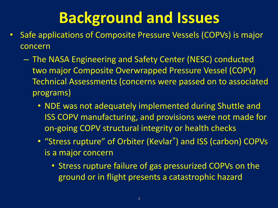
Background and Issues • Safe applications of Composite Pressure Vessels (COPVs) is major
concern
– The NASA Engineering and Safety Center (NESC) conducted two major Composite Overwrapped Pressure Vessel (COPV) Technical Assessments (concerns were passed on to associated programs)
• NDE was not adequately implemented during Shuttle and ISS COPV manufacturing, and provisions were not made for on-going COPV structural integrity or health checks
• “Stress rupture” of Orbiter (Kevlar®) and ISS (carbon) COPVs is a major concern
• Stress rupture failure of gas pressurized COPVs on the ground or in flight presents a catastrophic hazard
4
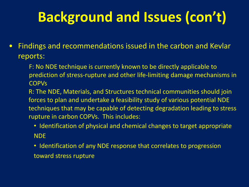
• Findings and recommendations issued in the carbon and Kevlar reports: F: No NDE technique is currently known to be directly applicable to
prediction of stress-rupture and other life-limiting damage mechanisms in COPVs R: The NDE, Materials, and Structures technical communities should join forces to plan and undertake a feasibility study of various potential NDE techniques that may be capable of detecting degradation leading to stress rupture in carbon COPVs. This includes:
• Identification of physical and chemical changes to target appropriate
NDE
• Identification of any NDE response that correlates to progression
toward stress rupture
Background and Issues (con’t)

Objective
• Develop and demonstrate NDE techniques for real-time characterization of CPVs and, where possible, identification of NDE capable of assessing stress rupture related strength degradation and/or making vessel life predictions (structural health monitoring or periodic inspection modes) – Secondary: Provide the COPV user and materials
community with quality carbon/epoxy (C/Ep) COPV stress rupture progression rate data
– Aid in modeling, manufacturing, and application of COPVs for NASA spacecraft
6
Technical Methodology/Approach
• The recent carbon stress rupture testing builds on previous Kevlar® composite projects – NNWG carbon stress rupture project 2008-2012
– NNWG Kevlar Stress Rupture 2006-2008
– Orbiter Kevlar testing 2006-2009
– On-going NESC Composite Pressure Vessel Working Group testing and analysis
• To support the effort, a team of NDE experts was selected from the NNWG membership, the NASA Engineering and Safety Center (NESC), academia, and industry, with the goal of accomplishing this project in a highly collaborative manner
7
8
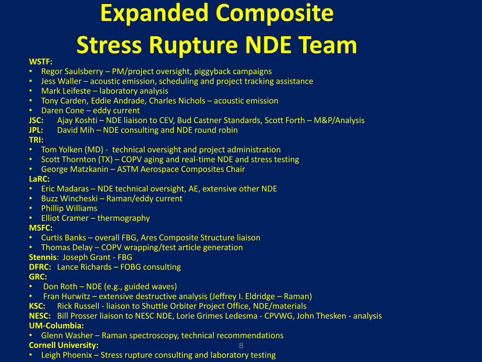
Expanded Composite Stress Rupture NDE Team
WSTF: • Regor Saulsberry – PM/project oversight, piggyback campaigns • Jess Waller – acoustic emission, scheduling and project tracking assistance • Mark Leifeste – laboratory analysis • Tony Carden, Eddie Andrade, Charles Nichols – acoustic emission • Daren Cone – eddy current JSC: Ajay Koshti – NDE liaison to CEV, Bud Castner Standards, Scott Forth – M&P/Analysis JPL: David Mih – NDE consulting and NDE round robin TRI: • Tom Yolken (MD) - technical oversight and project administration • Scott Thornton (TX) – COPV aging and real-time NDE and stress testing • George Matzkanin – ASTM Aerospace Composites Chair LaRC: • Eric Madaras – NDE technical oversight, AE, extensive other NDE • Buzz Wincheski – Raman/eddy current • Phillip Williams • Elliot Cramer – thermography MSFC: • Curtis Banks – overall FBG, Ares Composite Structure liaison • Thomas Delay – COPV wrapping/test article generation Stennis: Joseph Grant - FBG DFRC: Lance Richards – FOBG consulting GRC: • Don Roth – NDE (e.g., guided waves) • Fran Hurwitz – extensive destructive analysis (Jeffrey I. Eldridge – Raman) KSC: Rick Russell - liaison to Shuttle Orbiter Project Office, NDE/materials NESC: Bill Prosser liaison to NESC NDE, Lorie Grimes Ledesma - CPVWG, John Thesken - analysis UM-Columbia: • Glenn Washer – Raman spectroscopy, technical recommendations Cornell University: • Leigh Phoenix – Stress rupture consulting and laboratory testing
Technical Methodology/Approach (con’t)
• Correlate real-time NDE and instrumentation with stress rupture progression: – Include conventional and fiber-based acoustic emission (AE), and
distributive impact detection systems (DIDS) sensors
– Include GRC capacitance sensors, Métis sensors, AE arrays, Agilent passive wireless sensors (strain and temperature), and others developed by Small Business Innovation Research (SBIR) and Small Business Technology Transfer (STTR) to be added as available
• Other structural health monitoring (SHM) collaborations are openly invited
– Add in-situ portable Raman if feasible
– Evaluate feasibility of ISS vessel monitoring with AE sensors on interface lines
9
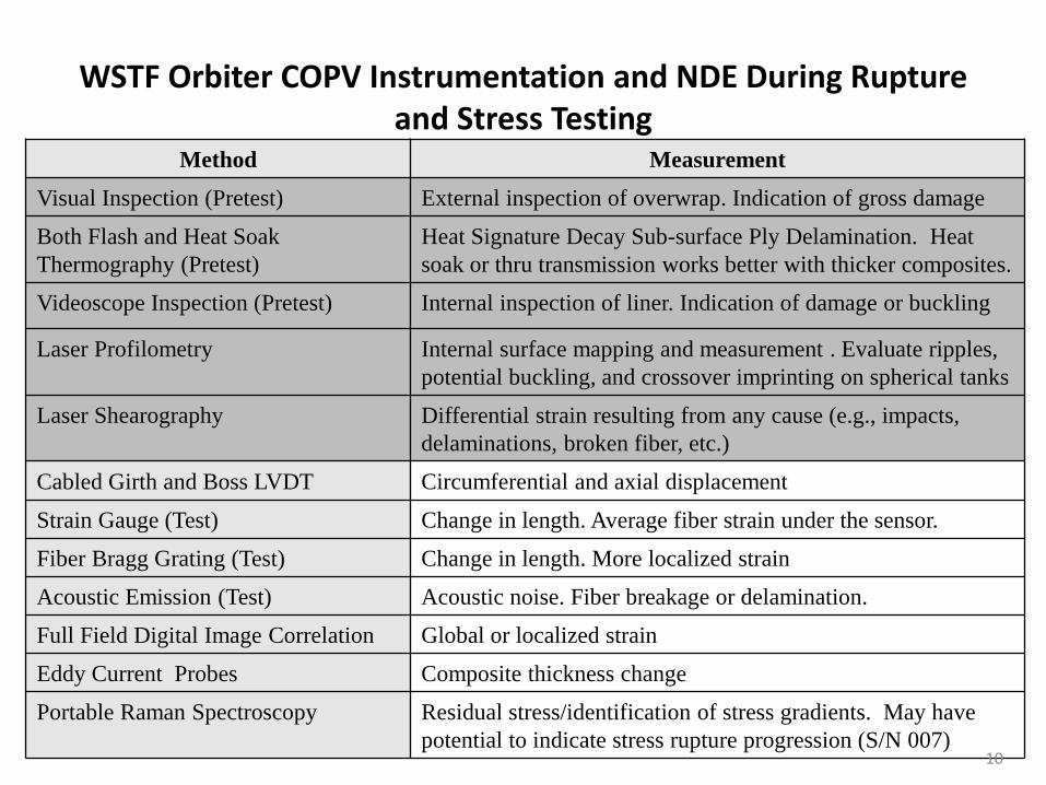
Method Measurement
Visual Inspection (Pretest) External inspection of overwrap. Indication of gross damage
Both Flash and Heat Soak
Thermography (Pretest)
Heat Signature Decay Sub-surface Ply Delamination. Heat
soak or thru transmission works better with thicker composites.
Videoscope Inspection (Pretest) Internal inspection of liner. Indication of damage or buckling
Laser Profilometry Internal surface mapping and measurement . Evaluate ripples,
potential buckling, and crossover imprinting on spherical tanks
Laser Shearography Differential strain resulting from any cause (e.g., impacts,
delaminations, broken fiber, etc.)
Cabled Girth and Boss LVDT Circumferential and axial displacement
Strain Gauge (Test) Change in length. Average fiber strain under the sensor.
Fiber Bragg Grating (Test) Change in length. More localized strain
Acoustic Emission (Test) Acoustic noise. Fiber breakage or delamination.
Full Field Digital Image Correlation Global or localized strain
Eddy Current Probes Composite thickness change
Portable Raman Spectroscopy Residual stress/identification of stress gradients. May have
potential to indicate stress rupture progression (S/N 007)
WSTF Orbiter COPV Instrumentation and NDE During Rupture and Stress Testing
10

Pretest NDE
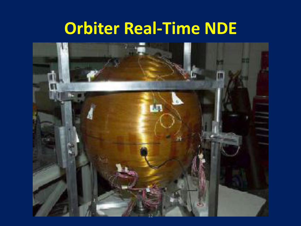
Orbiter Real-Time NDE
12
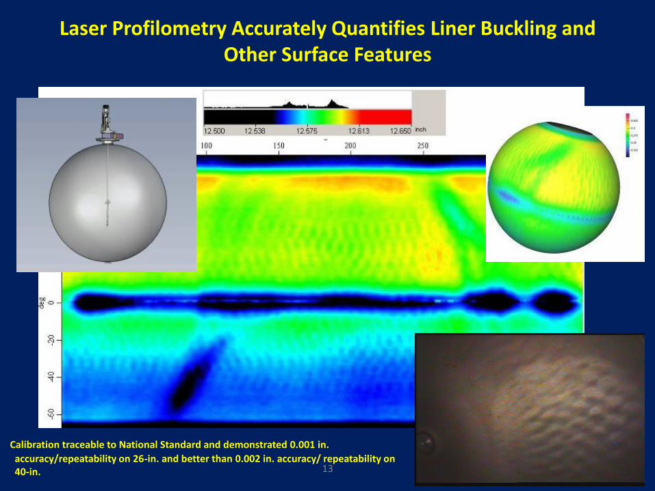
Laser Profilometry Accurately Quantifies Liner Buckling and Other Surface Features
13
Calibration traceable to National Standard and demonstrated 0.001 in.
accuracy/repeatability on 26-in. and better than 0.002 in. accuracy/ repeatability on 40-in.
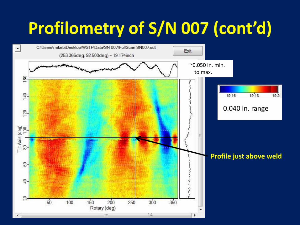
Profile just above weld
0.040 in. range
~0.050 in. min. to max.
Profilometry of S/N 007 (cont’d)
14
OMS Kevlar Pretest NDE Conclusion
• The large ripples around the girth weld raised a question, but no other observed indications were an issue with planned stress rupture testing – Eddy current sensors were placed over the peak of
each girth ripple and monitored during pressurization to verify the liner did not flex causing a metallic fatigue concern • Decrease of stand-off between the fixed composite surface
and liner ripple would indicate a liner buckle and associated air pocket
– Stand-off remained fixed during pressure cycles, indicating that the indications were not a concern
15
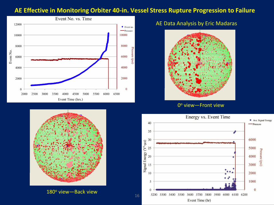
AE Effective in Monitoring Orbiter 40-in. Vessel Stress Rupture Progression to Failure
0o view—Front view
180o view—Back view
AE Data Analysis by Eric Madaras
16
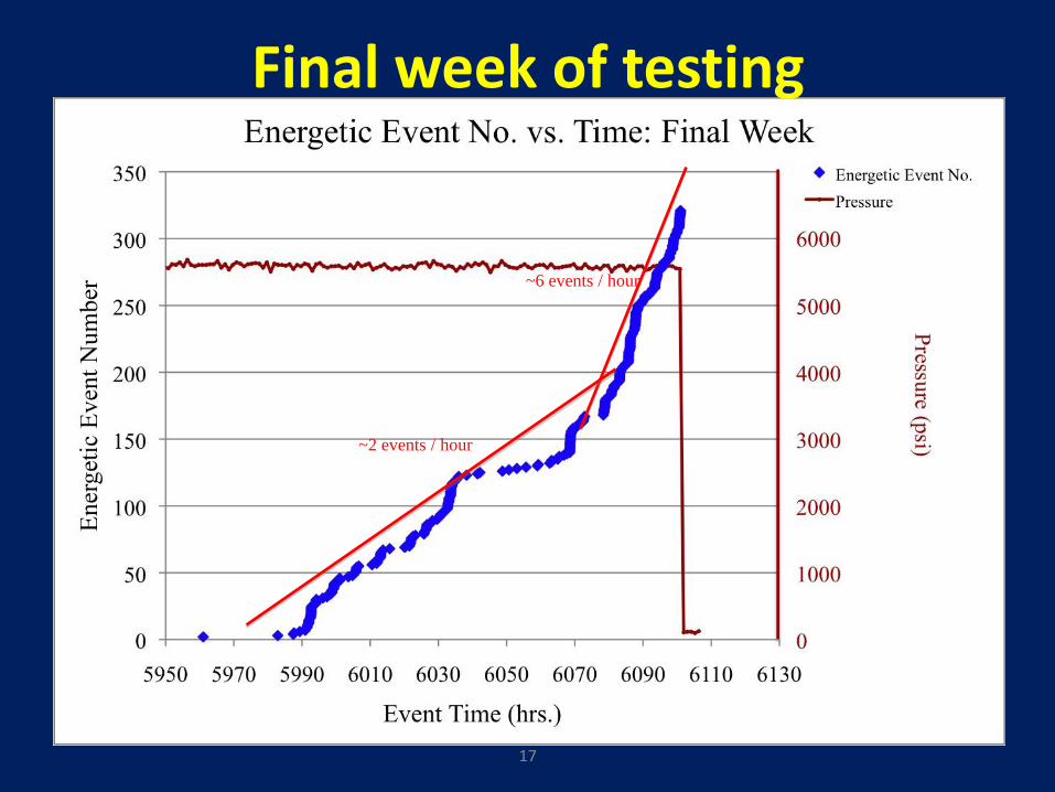
~2 events / hour
~6 events / hour
Final week of testing
17
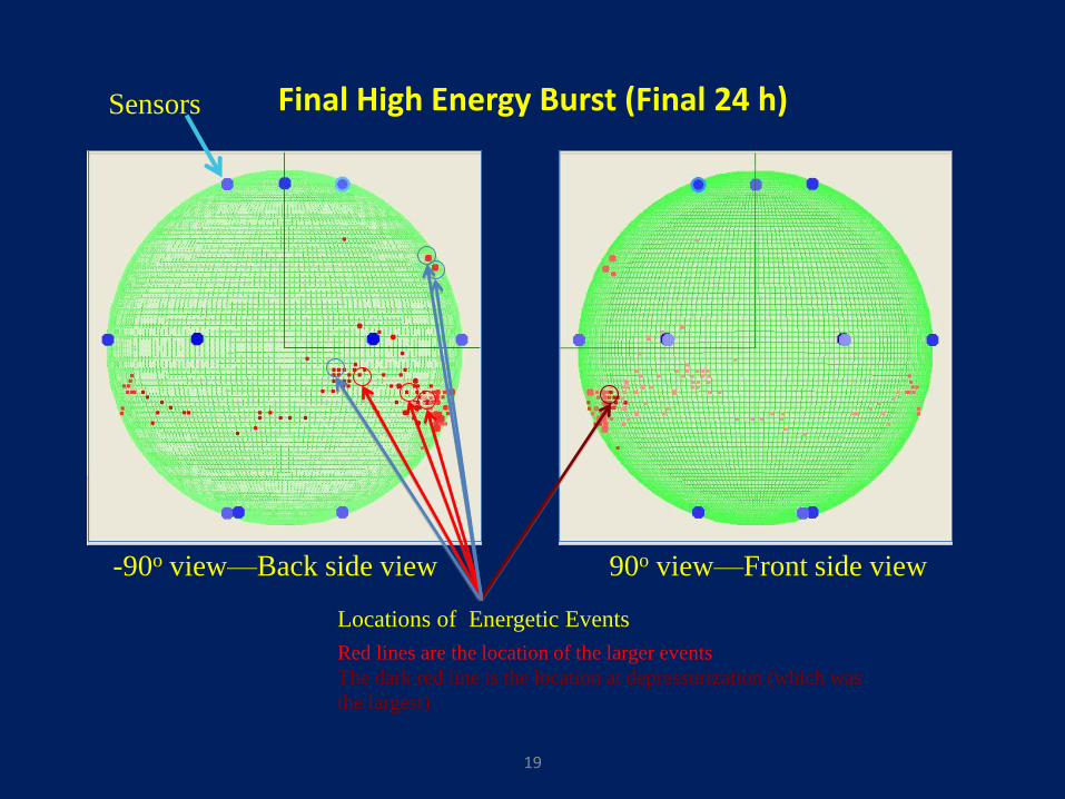
Final High Energy Burst (Final 24 h)
90o view—Front side view -90o view—Back side view
Locations of Energetic Events
Red lines are the location of the larger events
The dark red line is the location at depressurization (which was
the largest)
19
Sensors
AE Summary
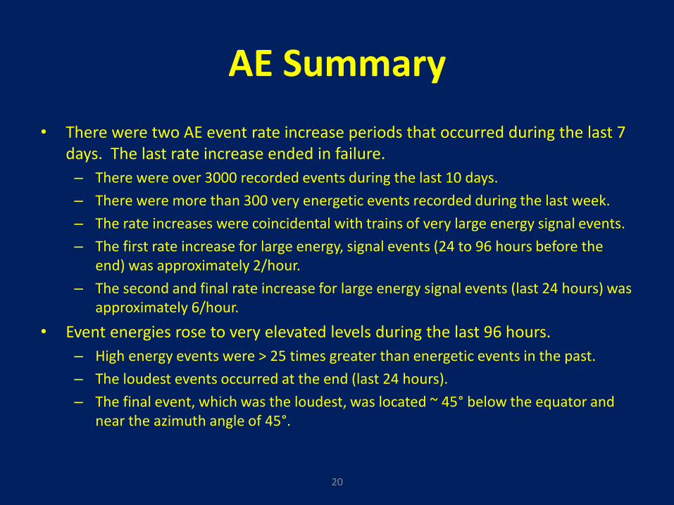
• There were two AE event rate increase periods that occurred during the last 7 days. The last rate increase ended in failure.
– There were over 3000 recorded events during the last 10 days.
– There were more than 300 very energetic events recorded during the last week.
– The rate increases were coincidental with trains of very large energy signal events.
– The first rate increase for large energy, signal events (24 to 96 hours before the end) was approximately 2/hour.
– The second and final rate increase for large energy signal events (last 24 hours) was approximately 6/hour.
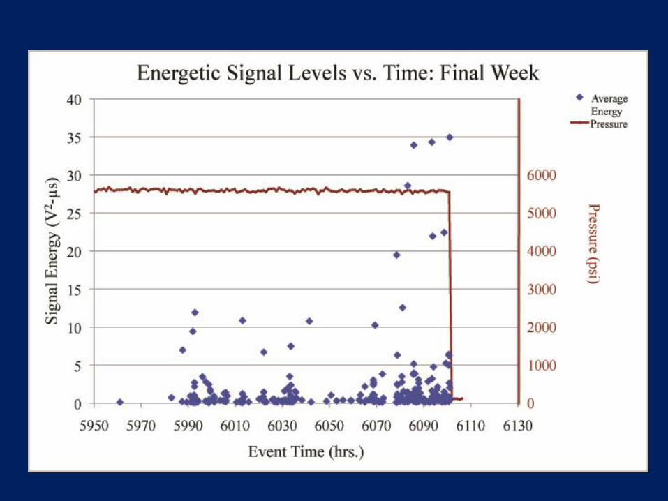
• Event energies rose to very elevated levels during the last 96 hours.
– High energy events were > 25 times greater than energetic events in the past.
– The loudest events occurred at the end (last 24 hours).
– The final event, which was the loudest, was located ~ 45° below the equator and near the azimuth angle of 45°.
20

Progress – Carbon Stress Rupture Project
• 100 carbon COPVs designed and fabricated
– 50 ea IM7 carbon vessels to represent ISS
– 50 ea from T1000 to represent Orion and potential future NASA spacecraft
– 6.3 in. dia., 6061 T6 aluminum liners, nominal 7500 psi burst to provide adequate carbon thickness
– Same lots of fiber used and many strand tests made to ensure quality
– Plant trips to observe winding process and witness burst tests
• NASA Engineering Safety Center (NESC) assisted with comprehensive modeling of vessels in Abacus® to identify the mechanical response
– WSTF modeled in Genoa™ and got similar results
– Separate autofrettage tests done on identical bottles on NESC funding to evaluate response as compared to the model
21
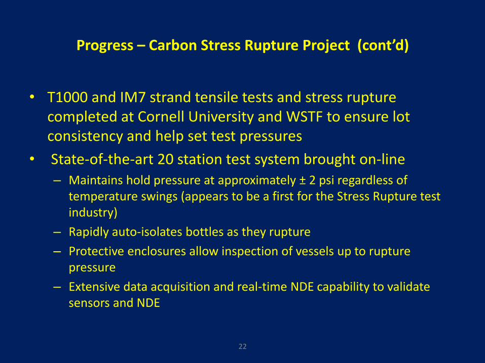
Progress – Carbon Stress Rupture Project (cont’d)
• T1000 and IM7 strand tensile tests and stress rupture completed at Cornell University and WSTF to ensure lot consistency and help set test pressures
• State-of-the-art 20 station test system brought on-line – Maintains hold pressure at approximately ± 2 psi regardless of
temperature swings (appears to be a first for the Stress Rupture test industry)
– Rapidly auto-isolates bottles as they rupture
– Protective enclosures allow inspection of vessels up to rupture pressure
– Extensive data acquisition and real-time NDE capability to validate sensors and NDE
22
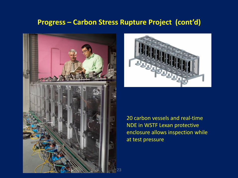
Progress – Carbon Stress Rupture Project (cont’d)
23
20 carbon vessels and real-time NDE in WSTF Lexan protective enclosure allows inspection while at test pressure
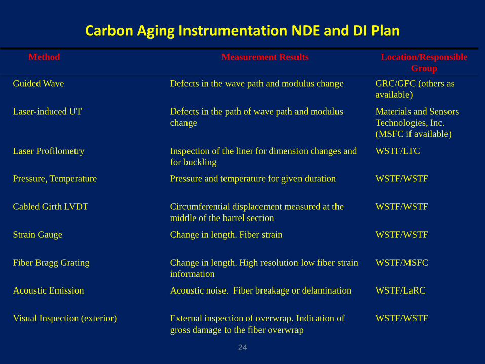
Carbon Aging Instrumentation NDE and DI Plan
24
Guided Wave Defects in the wave path and modulus change GRC/GFC (others as
available)
Laser-induced UT Defects in the path of wave path and modulus
change
Materials and Sensors
Technologies, Inc.
(MSFC if available)
Laser Profilometry Inspection of the liner for dimension changes and
for buckling
WSTF/LTC
Pressure, Temperature Pressure and temperature for given duration WSTF/WSTF
Cabled Girth LVDT Circumferential displacement measured at the
middle of the barrel section
WSTF/WSTF
Strain Gauge Change in length. Fiber strain WSTF/WSTF
Fiber Bragg Grating Change in length. High resolution low fiber strain
information
WSTF/MSFC
Acoustic Emission Acoustic noise. Fiber breakage or delamination WSTF/LaRC
Visual Inspection (exterior) External inspection of overwrap. Indication of
gross damage to the fiber overwrap
WSTF/WSTF
Method Measurement Results Location/Responsible
Group
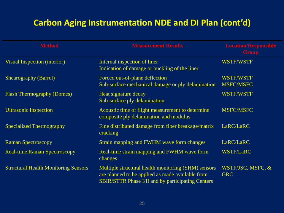
Carbon Aging Instrumentation NDE and DI Plan (cont’d)
25
Method Measurement Results Location/Responsible
Group
Visual Inspection (interior) Internal inspection of liner
Indication of damage or buckling of the liner
WSTF/WSTF
Shearography (Barrel) Forced out-of-plane deflection
Sub-surface mechanical damage or ply delamination
WSTF/WSTF
MSFC/MSFC
Flash Thermography (Domes) Heat signature decay
Sub-surface ply delamination
WSTF/WSTF
Ultrasonic Inspection Acoustic time of flight measurement to determine
composite ply delamination and modulus
MSFC/MSFC
Specialized Thermography Fine distributed damage from fiber breakage/matrix
cracking
LaRC/LaRC
Raman Spectroscopy Strain mapping and FWHM wave form changes LaRC/LaRC
Real-time Raman Spectroscopy Real-time strain mapping and FWHM wave form
changes
WSTF/LaRC
Structural Health Monitoring Sensors Multiple structural health monitoring (SHM) sensors
are planned to be applied as made available from
SBIR/STTR Phase I/II and by participating Centers
WSTF/JSC, MSFC, &
GRC
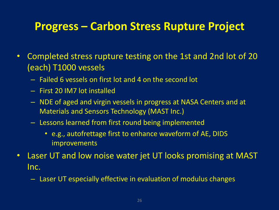
Progress – Carbon Stress Rupture Project
• Completed stress rupture testing on the 1st and 2nd lot of 20 (each) T1000 vessels – Failed 6 vessels on first lot and 4 on the second lot
– First 20 IM7 lot installed
– NDE of aged and virgin vessels in progress at NASA Centers and at Materials and Sensors Technology (MAST Inc.)
– Lessons learned from first round being implemented
• e.g., autofrettage first to enhance waveform of AE, DIDS improvements
• Laser UT and low noise water jet UT looks promising at MAST Inc. – Laser UT especially effective in evaluation of modulus changes
26
Progress – Carbon Stress Rupture Project (cont’d)
• NESC correlating stress rupture progression rate data with existing community database
– Carefully controlled data should improve database
– Profilometry also being done to directly evaluate residual deformation and growth (strain measurement) over the stress rupture period
27
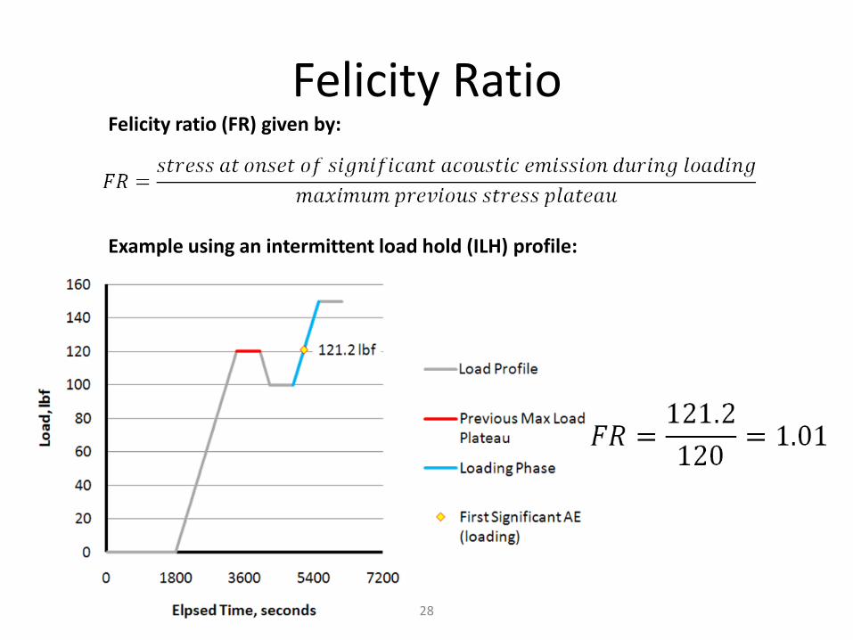
Felicity Ratio
28
Example using an intermittent load hold (ILH) profile:
Felicity ratio (FR) given by:
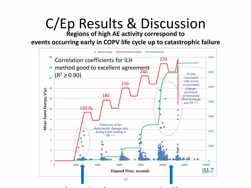
C/Ep Results & Discussion
29
Regions of high AE activity correspond to events occurring early in COPV life cycle up to catastrophic failure
autofrettage/proof late life
150 lbf
180
210
270
240
IM-7
Correlation coefficients for ILH method good to excellent agreement (R2 ≥ 0.90)

Proof-of-concept Felicity ratio analysis of an IM-7 reinforced C/Ep COPV (blue dots) superimposed on Kevlar® 49 (green line), T1000 (red line), and IM7 (blue line) single tow data
IM-7 tow data (solid blue line) consistent with IM-7 COPV data (blue symbols)
Correlation of IM7 C/Ep COPV AE Felicity Ratio to Strand Data
30
FR and Shelby Ratio (SR) show some
promise of predictability of stress-
rupture “when related to damage-site
monitoring”
Virgin pressurization AE can provide a
measure of repeatability of COPV
manufacturing process
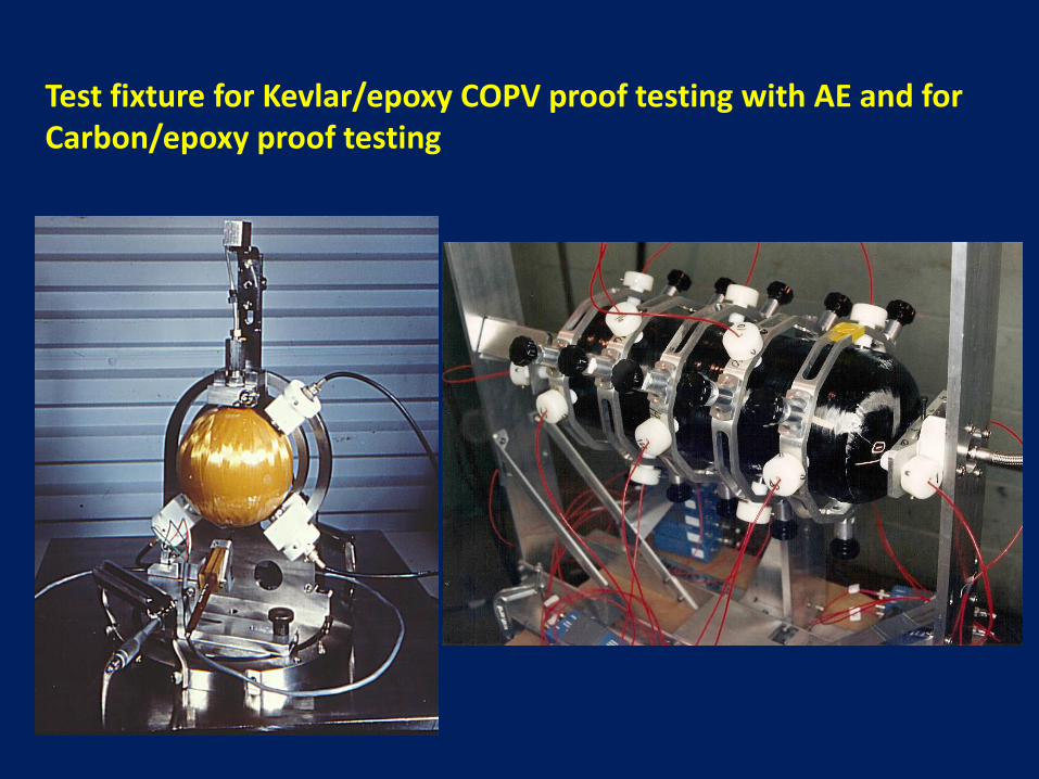
Test fixture for Kevlar/epoxy COPV proof testing with AE and for Carbon/epoxy proof testing
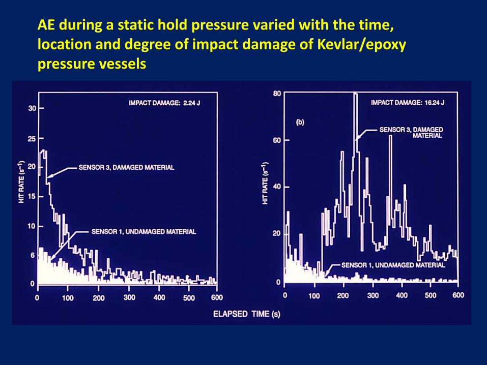
AE during a static hold pressure varied with the time, location and degree of impact damage of Kevlar/epoxy pressure vessels
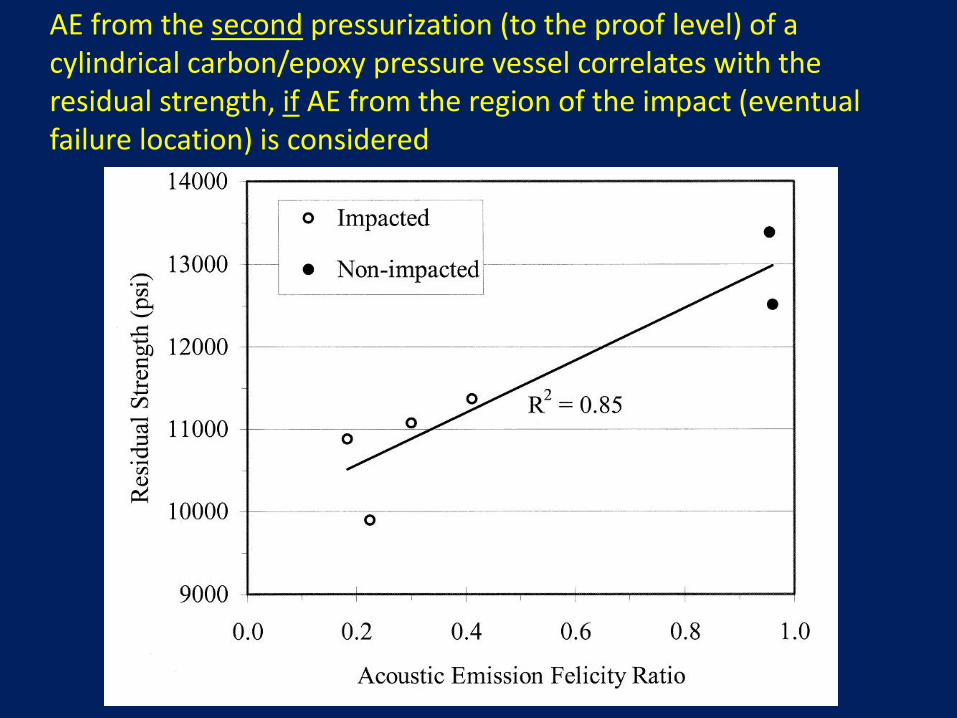
AE from the second pressurization (to the proof level) of a cylindrical carbon/epoxy pressure vessel correlates with the residual strength, if AE from the region of the impact (eventual failure location) is considered
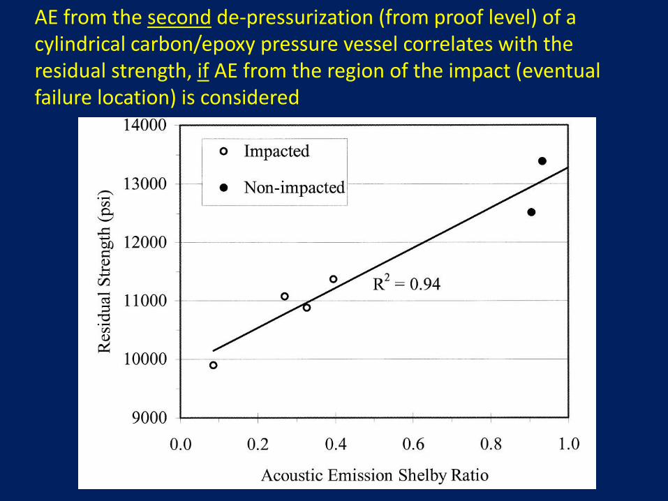
AE from the second de-pressurization (from proof level) of a cylindrical carbon/epoxy pressure vessel correlates with the residual strength, if AE from the region of the impact (eventual failure location) is considered
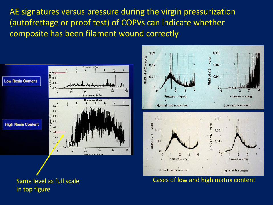
AE signatures versus pressure during the virgin pressurization (autofrettage or proof test) of COPVs can indicate whether composite has been filament wound correctly
Carbon fiber/epoxy sphere
Kevlar49 fiber/epoxy sphere
Same level as full scale in top figure
Cases of low and high matrix content
Conclusion
• NDE has proven highly effective in real-time characterization of COPVs during testing
• NDE is reasonably effective in evaluating the health of COPVs, but still more work is needed to make it more quantitative and predictive
• Overall, a well controlled and informative Carbon COPV Stress Rupture test is being accomplished – Collaboration on SHM sensor evaluation is invited
37
“An inspection master plan shall be established prior to start of fabrication. The plan shall specify appropriate inspection points and inspection techniques for use throughout the program, beginning with material procurement and continuing through fabrication, assembly, acceptance-proof test, and operation, as appropriate. In establishing inspection points and inspection techniques, consideration shall be given to the material characteristics, fabrication processes, design concepts, structural configuration, corrosion control, and accessibility for inspection of flaws. Acceptance and rejection standards shall be established for each phase of inspection, and for each type of inspection technique.”
The NASA Engineering and Safety Center Technical Assessment Report (Par 4.5.1) has established a requirement that, for the NORS vessels (S-081-2000)….
Need for consensus standards
According to the CSA: “A standard is a document that specifies minimum requirements for design, construction, performance and quality control during production of the product”
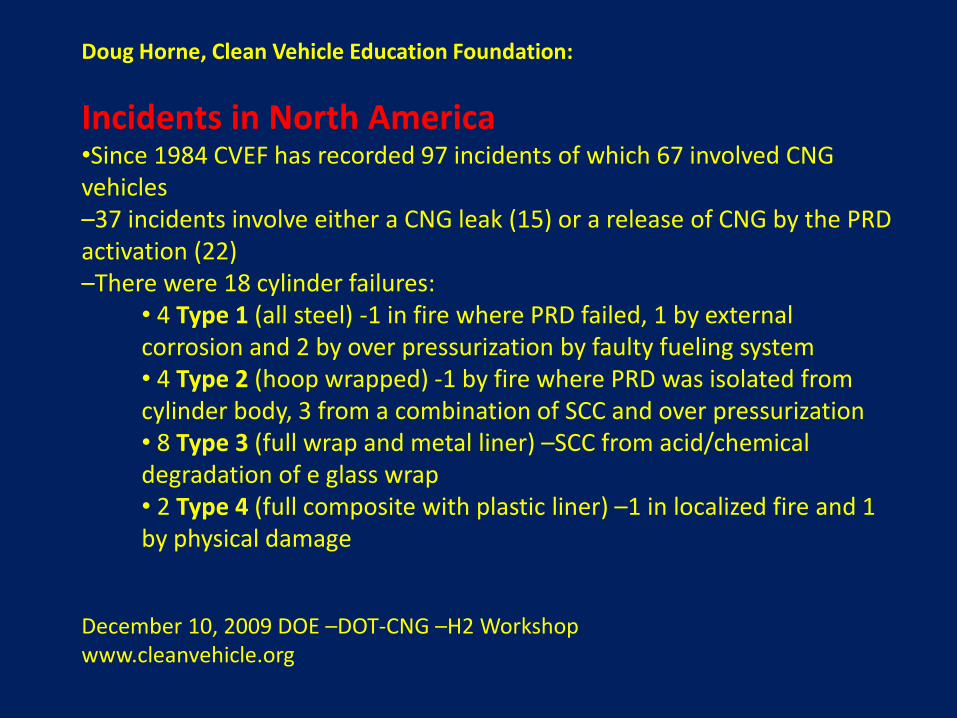
Doug Horne, Clean Vehicle Education Foundation:
Incidents in North America •Since 1984 CVEF has recorded 97 incidents of which 67 involved CNG vehicles –37 incidents involve either a CNG leak (15) or a release of CNG by the PRD activation (22) –There were 18 cylinder failures:
• 4 Type 1 (all steel) -1 in fire where PRD failed, 1 by external corrosion and 2 by over pressurization by faulty fueling system • 4 Type 2 (hoop wrapped) -1 by fire where PRD was isolated from cylinder body, 3 from a combination of SCC and over pressurization • 8 Type 3 (full wrap and metal liner) –SCC from acid/chemical degradation of e glass wrap • 2 Type 4 (full composite with plastic liner) –1 in localized fire and 1 by physical damage
December 10, 2009 DOE –DOT-CNG –H2 Workshop www.cleanvehicle.org
In the U.S…….. It will take only one catastrophic, well-publicized COPV explosion to send CNG or hydrogen fueled vehicles (or NASA) back to the drawing board. We need to be proactive, not reactive with regards to harmonized standards and improved COPV manufacturing, testing and utilization. An extensive database on COPV performance (pressurized-cyclic, pressurized-static, chemical and environmental effects, manufacturing variability, etc.) should be developed, along with a comprehensive study of proposed and existing NDE techniques that can monitor COPV integrity and reliability from the start of the manufacturing process through the life of the vessel.