Embed Size (px)
Citation preview
Venterre - Parc éolien de Saint-Valentin Annexes - Volume 3 Étude d'impact sur l'environnement – janvier 2010
ANNEXE C
ÉTUDE GÉOTECHNIQUE PRÉLIMINAIRE
REPORT Preliminary Geotechnical Investigation Saint-Blaise / Saint-Valentin, Quebec TCI RENEWABLES
PROJECT NO. 1023239
PROJECT NO. 1023239 REPORT TO TCI Renewables
227 Des Pyrenees Avenue, Suite 2 Saint-Lambert Montreal, Quebec J4S 1L5
FOR Preliminary Geotechnical Investigation
ON Saint-Blaise / Saint-Valentin, Quebec
April 16, 2007
Jacques Whitford Ltd.
8170 Montview Road, Suite 100 Mount Royal, Quebec
H4P 2L7
Phone: 514 739-0708 Fax: 514 739-8499
www.jacqueswhitford.com
© 2007 PROJECT 1023239 April 16, 2007 i
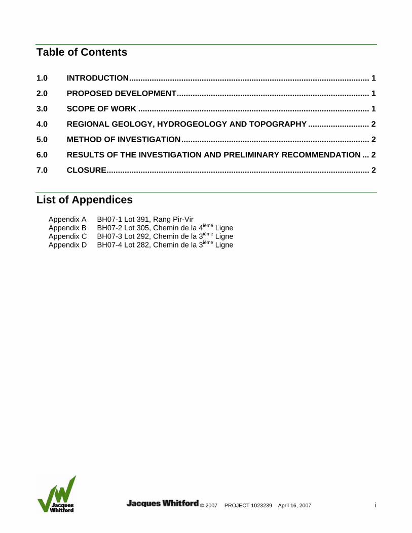
Table of Contents
1.0 INTRODUCTION.......................................................................................................... 1
2.0 PROPOSED DEVELOPMENT..................................................................................... 1
3.0 SCOPE OF WORK ...................................................................................................... 1
4.0 REGIONAL GEOLOGY, HYDROGEOLOGY AND TOPOGRAPHY ........................... 2
5.0 METHOD OF INVESTIGATION................................................................................... 2
6.0 RESULTS OF THE INVESTIGATION AND PRELIMINARY RECOMMENDATION ... 2
7.0 CLOSURE.................................................................................................................... 2
List of Appendices
Appendix A BH07-1 Lot 391, Rang Pir-Vir Appendix B BH07-2 Lot 305, Chemin de la 4ième Ligne Appendix C BH07-3 Lot 292, Chemin de la 3ième Ligne Appendix D BH07-4 Lot 282, Chemin de la 3ième Ligne
© 2007 PROJECT 1023239 April 16, 2007 1
1.0 INTRODUCTION This report presents the results of a Preliminary Geotechnical Investigation carried out for four potential wind farm sites near the communities of Saint-Valentin and Saint-Blaise-sur-Richelieu in the province of Quebec. The work was carried out in general accordance with our proposal No. 1019274 dated November 9, 2006, issued to TCI Renewables (TCI).
This report has been prepared specifically and solely as a preliminary investigation for the four potential wind farm sites described herein. It presents the factual results of the preliminary geotechnical investigation, an assessment of potential geotechnical challenges or constraints for the proposed type of development, and preliminary geotechnical recommendations for use in conceptual designs. Additional geotechnical investigation work and analysis will be required as part of future detailed design work for each of the potential sites.
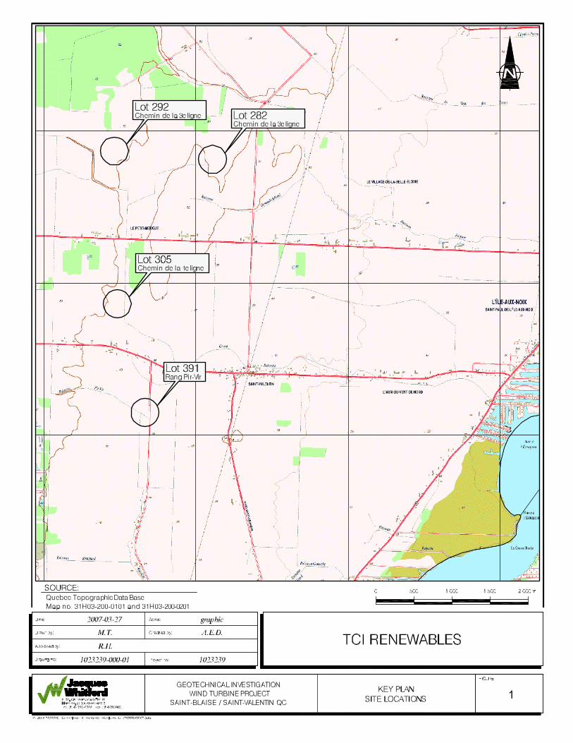
2.0 PROPOSED DEVELOPMENT The four potential wind farm sites are located near the communities of Saint-Valentin and Saint-Blaise-sur-Richelieu and occupy approximately a 10 km radius area. The site locations are shown on the Key Plan, Drawing No. 1. The site locations are described as follow:
Street 1st Intersection 2nd Intersection Details Borehole
Rang Pir-Vir Chemin de la 4ième Ligne 35ième Avenue Lot 391 BH07-1
Chemin de la 4ième Ligne Chemin Louis-Cyr Montée Guay Lot 305 BH07-2
Chemin de la 3ième Ligne Chemin Louis-Cyr Montée du petit rang Lot 292 BH07-3
Chemin de la 3ième Ligne Chemin Louis-Cyr Montée du petit rang Lot 282 BH07-4
All four of the potential wind farm sites are currently occupied by agricultural lands.
3.0 SCOPE OF WORK The scope of work for this preliminary geotechnical investigation included the following:
Conducting a field investigation consisting of four boreholes;
Supplementing the field information with limited in situ and laboratory testing, as required, to provide preliminary characterization of the subsurface conditions;
Summarizing the field and laboratory information in a report including borehole records, a borehole location plan, preliminary geotechnical recommendations for foundations, and a discussion of potential geotechnical challenges or constraints for the proposed development.
© 2007 PROJECT 1023239 April 16, 2007 2
4.0 REGIONAL GEOLOGY, HYDROGEOLOGY AND TOPOGRAPHY Based on available surficial geology maps (Appalachian mineral deposit Map DV87-19, Quaternary geology of the great Montreal region Map2), the regional surficial soils generally consist of marine deposits including gravel, sand, silt and clay. The bedrock varies from a calcareous mudstone of the Stony Point Formation to a crystalline limestone/shale from the Laval Formation.
5.0 METHOD OF INVESTIGATION Prior to the commencement of the investigation, Jacques Whitford personnel made arrangements to verify the locations of underground utilities near the proposed borehole locations.
The field work for the preliminary geotechnical investigation consisting of drilling four boreholes was carried out on March 13th, 15th, 16th and 17th, 2007, using a track mounted CME 75 drill.
The subsurface stratigraphy encountered in the boreholes was recorded in the field by our geotechnical personnel. Split spoon soil samples were collected during the performance of Standard Penetration Tests (SPT).
All soil samples were returned to our laboratory where they were subjected to detailed visual classification by a geotechnical engineer. Soil description and identification were made in accordance with ASTM Standard D2488 (Visual-Manual Method) and D2487 (Classification of Soils for Engineering Purposes). Selected soil samples were tested for moisture content and grain size distribution. Samples remaining after testing will be stored for a period of one (1) month after issuance of this report. Samples will then be discarded unless we are otherwise directed.
Borehole locations were established in the field by Jacques Whitford personnel using a GPS device. Groundwater levels were measured on March 25, 2006. The ground surface elevations at the borehole locations are to be determined by TCI and forwarded to Jacques Whitford.
6.0 RESULTS OF THE INVESTIGATION AND PRELIMINARY RECOMMENDATION
The results of the investigation and associated preliminary recommendations are provided separately for each site within Appendix A, B, C and D.
7.0 CLOSURE This report has been prepared for the sole benefit of TCI, and may not be used by any third party without the express written consent of Jacques Whitford Limited and TCI. Any use which a third party makes of this report is the responsibility of such third party.
This report is based on the site conditions encountered by Jacques Whitford at the time of the work, and at the specific testing and/or sampling locations, and can only be extrapolated to a limited extent around these locations. The extent depends on the variability of soil / rock and groundwater conditions
© 2007 PROJECT 1023239 April 16, 2007 3
as influenced by geological processes, construction activities and site use. Should any conditions at the site be encountered which differ from those at the test locations, we require that we be notified immediately in order to permit reassessment of our findings. It is noted that further field investigation will be required prior to final design.
We trust the above information meets with your present requirements. Should you have any questions or require further information, please do not hesitate to contact us at your convenience.
We thank you for the opportunity to be of service to you.
Yours very truly,
JACQUES WHITFORD LIMITED
Original Signed By
Afif El-Dana, ing.jr. Project Manager
Original Signed By
J.G.A. Raymond Haché, M.Sc., P.Eng., ing., PMP Principal and Senior Service Director, Geotechnical and Materials Engineering
AED/RH/sk
Page 1 of 3
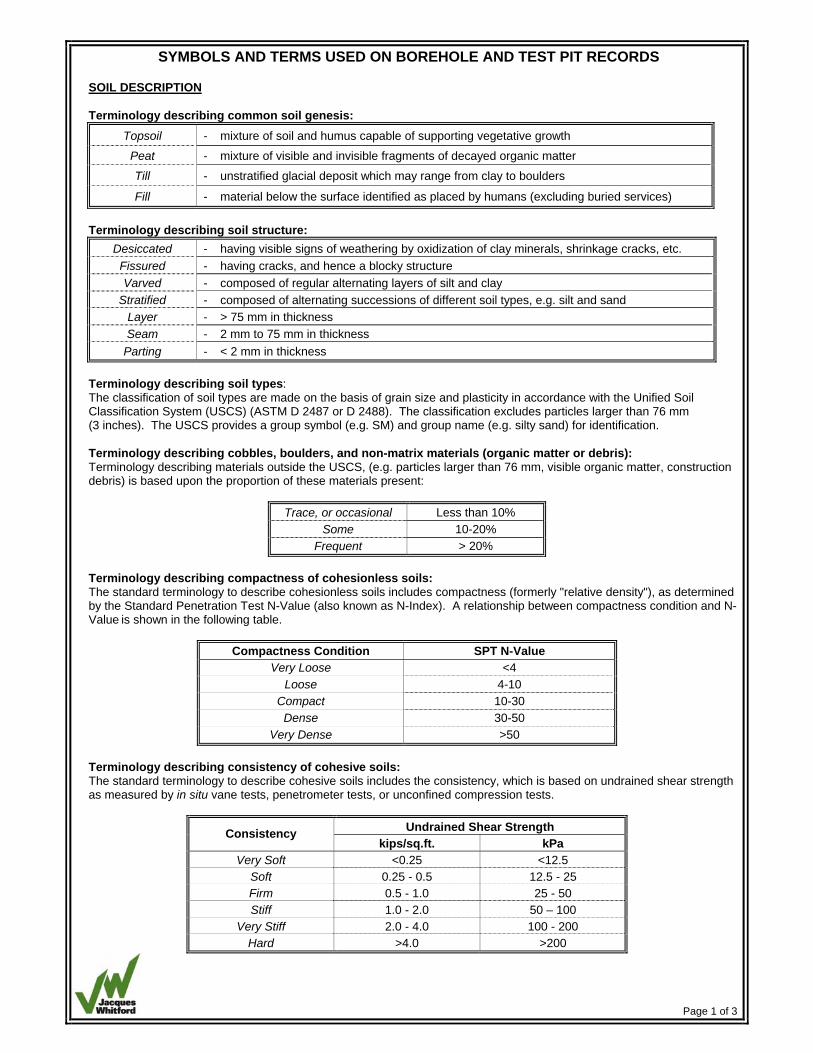
SYMBOLS AND TERMS USED ON BOREHOLE AND TEST PIT RECORDS SOIL DESCRIPTION Terminology describing common soil genesis:
Topsoil - mixture of soil and humus capable of supporting vegetative growth Peat - mixture of visible and invisible fragments of decayed organic matter
Till - unstratified glacial deposit which may range from clay to boulders
Fill - material below the surface identified as placed by humans (excluding buried services) Terminology describing soil structure:
Desiccated - having visible signs of weathering by oxidization of clay minerals, shrinkage cracks, etc. Fissured - having cracks, and hence a blocky structure Varved - composed of regular alternating layers of silt and clay
Stratified - composed of alternating successions of different soil types, e.g. silt and sand Layer - > 75 mm in thickness Seam - 2 mm to 75 mm in thickness
Parting - < 2 mm in thickness Terminology describing soil types: The classification of soil types are made on the basis of grain size and plasticity in accordance with the Unified Soil Classification System (USCS) (ASTM D 2487 or D 2488). The classification excludes particles larger than 76 mm (3 inches). The USCS provides a group symbol (e.g. SM) and group name (e.g. silty sand) for identification. Terminology describing cobbles, boulders, and non-matrix materials (organic matter or debris): Terminology describing materials outside the USCS, (e.g. particles larger than 76 mm, visible organic matter, construction debris) is based upon the proportion of these materials present:
Trace, or occasional Less than 10% Some 10-20%
Frequent > 20% Terminology describing compactness of cohesionless soils: The standard terminology to describe cohesionless soils includes compactness (formerly "relative density"), as determined by the Standard Penetration Test N-Value (also known as N-Index). A relationship between compactness condition and N-Value is shown in the following table.
Compactness Condition SPT N-Value Very Loose <4
Loose 4-10 Compact 10-30 Dense 30-50
Very Dense >50 Terminology describing consistency of cohesive soils: The standard terminology to describe cohesive soils includes the consistency, which is based on undrained shear strength as measured by in situ vane tests, penetrometer tests, or unconfined compression tests.
Undrained Shear Strength Consistency kips/sq.ft. kPa
Very Soft <0.25 <12.5 Soft 0.25 - 0.5 12.5 - 25 Firm 0.5 - 1.0 25 - 50 Stiff 1.0 - 2.0 50 – 100
Very Stiff 2.0 - 4.0 100 - 200 Hard >4.0 >200
Page 2 of 3
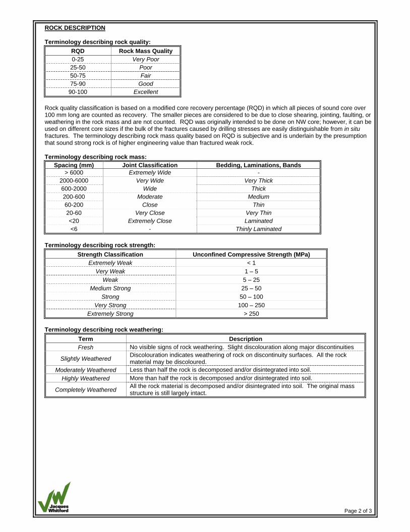
ROCK DESCRIPTION Terminology describing rock quality:
RQD Rock Mass Quality 0-25 Very Poor 25-50 Poor 50-75 Fair 75-90 Good
90-100 Excellent Rock quality classification is based on a modified core recovery percentage (RQD) in which all pieces of sound core over 100 mm long are counted as recovery. The smaller pieces are considered to be due to close shearing, jointing, faulting, or weathering in the rock mass and are not counted. RQD was originally intended to be done on NW core; however, it can be used on different core sizes if the bulk of the fractures caused by drilling stresses are easily distinguishable from in situ fractures. The terminology describing rock mass quality based on RQD is subjective and is underlain by the presumption that sound strong rock is of higher engineering value than fractured weak rock. Terminology describing rock mass:
Spacing (mm) Joint Classification Bedding, Laminations, Bands > 6000 Extremely Wide -
2000-6000 Very Wide Very Thick 600-2000 Wide Thick 200-600 Moderate Medium 60-200 Close Thin 20-60 Very Close Very Thin <20 Extremely Close Laminated <6 - Thinly Laminated
Terminology describing rock strength:
Strength Classification Unconfined Compressive Strength (MPa) Extremely Weak < 1
Very Weak 1 – 5 Weak 5 – 25
Medium Strong 25 – 50 Strong 50 – 100
Very Strong 100 – 250 Extremely Strong > 250
Terminology describing rock weathering:
Term Description Fresh No visible signs of rock weathering. Slight discolouration along major discontinuities
Slightly Weathered Discolouration indicates weathering of rock on discontinuity surfaces. All the rock material may be discoloured.
Moderately Weathered Less than half the rock is decomposed and/or disintegrated into soil. Highly Weathered More than half the rock is decomposed and/or disintegrated into soil.
Completely Weathered All the rock material is decomposed and/or disintegrated into soil. The original mass structure is still largely intact.
Page 3 of 3
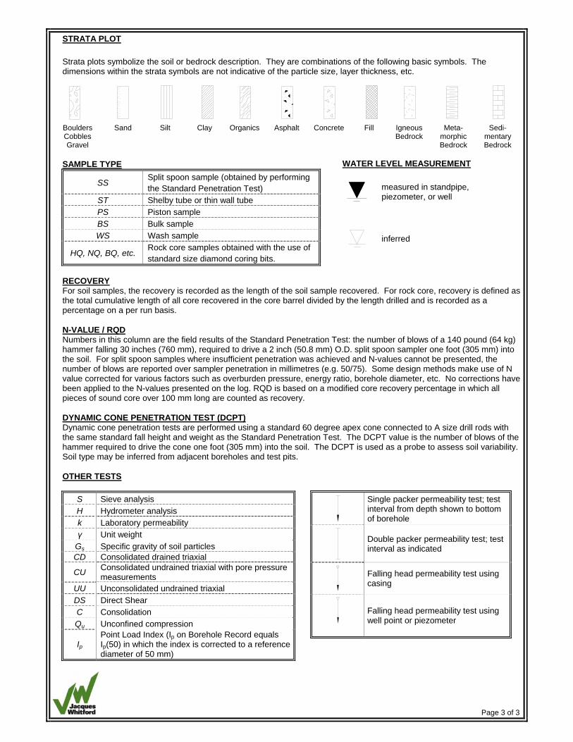
STRATA PLOT Strata plots symbolize the soil or bedrock description. They are combinations of the following basic symbols. The dimensions within the strata symbols are not indicative of the particle size, layer thickness, etc.
Boulders Cobbles Gravel
Sand Silt Clay Organics Asphalt Concrete Fill Igneous Bedrock
Meta-morphic Bedrock
Sedi-mentary Bedrock
SAMPLE TYPE
SS Split spoon sample (obtained by performing the Standard Penetration Test)
ST Shelby tube or thin wall tube PS Piston sample BS Bulk sample WS Wash sample
HQ, NQ, BQ, etc. Rock core samples obtained with the use of standard size diamond coring bits.
RECOVERY For soil samples, the recovery is recorded as the length of the soil sample recovered. For rock core, recovery is defined as the total cumulative length of all core recovered in the core barrel divided by the length drilled and is recorded as a percentage on a per run basis. N-VALUE / RQD Numbers in this column are the field results of the Standard Penetration Test: the number of blows of a 140 pound (64 kg) hammer falling 30 inches (760 mm), required to drive a 2 inch (50.8 mm) O.D. split spoon sampler one foot (305 mm) into the soil. For split spoon samples where insufficient penetration was achieved and N-values cannot be presented, the number of blows are reported over sampler penetration in millimetres (e.g. 50/75). Some design methods make use of N value corrected for various factors such as overburden pressure, energy ratio, borehole diameter, etc. No corrections have been applied to the N-values presented on the log. RQD is based on a modified core recovery percentage in which all pieces of sound core over 100 mm long are counted as recovery. DYNAMIC CONE PENETRATION TEST (DCPT) Dynamic cone penetration tests are performed using a standard 60 degree apex cone connected to A size drill rods with the same standard fall height and weight as the Standard Penetration Test. The DCPT value is the number of blows of the hammer required to drive the cone one foot (305 mm) into the soil. The DCPT is used as a probe to assess soil variability. Soil type may be inferred from adjacent boreholes and test pits. OTHER TESTS
S Sieve analysis H Hydrometer analysis k Laboratory permeability γ Unit weight
Gs Specific gravity of soil particles CD Consolidated drained triaxial
CU Consolidated undrained triaxial with pore pressure measurements
UU Unconsolidated undrained triaxial DS Direct Shear C Consolidation Qu Unconfined compression
Ip Point Load Index (Ip on Borehole Record equals Ip(50) in which the index is corrected to a reference diameter of 50 mm)
WATER LEVEL MEASUREMENT
measured in standpipe, piezometer, or well
inferred
Single packer permeability test; test interval from depth shown to bottom of borehole
Double packer permeability test; test interval as indicated
Falling head permeability test using casing
Falling head permeability test using well point or piezometer
APPENDIX A BH07-1 Lot 391, Rang Pir-Vir
Appendix A: BH07-1 Lot 391, Rang Pir-Vir Page 1 of 2
1.0 FINDINGS The subsurface conditions encountered at the Lot 391, Rang Pir-Vir, location are described in detail on the attached Borehole Record and are summarized in the following paragraphs. An explanation of the symbols and terms used to describe the Borehole Records is also provided.
1.1 Subsurface Information
Borehole BH07-1 was extended to practical SPT refusal at a depth of 15.35 m. The observed stratigraphy consisted of 0.3 m of topsoil over 1.2 m of loose brown sand with silt (SP-SM) layer. Underlying the sand was around 6.7 m of inorganic lean clay (CL) of medium plasticity with in situ shear strength values ranging from 55 to 60 kPa followed by 7.65 m of granular soil ranging from loose silt (MH) to sand and gravel (SP) becoming coarser and denser with depth.
The groundwater level was measured at a depth of 0.45 m below existing ground surface on March 25, 2007. Groundwater levels typically vary with seasonal changes, therefore the groundwater conditions at the time of construction may differ from those encountered during the investigation.
Laboratory testing of representative samples consisted of Atterberg Limits testing conducted on the clay in addition to moisture contents testing. The average Liquid Limit of representative samples was 42 with a Plasticity Index of 24.The moisture content ranged from 22% to 72%.
2.0 DISCUSSION AND RECOMMENDATIONS It is understood that a concrete pad type foundation is proposed to support the wind turbine tower. The pad would be octagonal and would be placed at a depth of around 2.4 m. The proposed turbine has a height (at the hub) of 70 m.
2.1 Geotechnical resistance - Spread Footings
The clay encountered from 2.3 m to 8.2 m is a stiff lean clay. Based on the results of the in situ undrained shear strength testing and laboratory tasting, it is estimated that the geological preconsolidation on this clay is in the order of 150 to 170 kPa above the existing overburden pressures. For preliminary foundation design purposes, the following geotechnical bearing resistances may be considered for footings founded on the clay at the site:
Geotechnical Resistances Footing Size ULS 1 SLS 2 6 m Diameter 170 kPa 130 kPa
10 m Diameter 170 kPa 110 kPa
Appendix A: BH07-1 Lot 391, Rang Pir-Vir Page 2 of 2
Notes:
1) The geotechnical resistance at Ultimate Limit States (ULS) is based on the nominal ultimate resistance multiplied by a geotechnical resistance factor of 0.5.
2) The geotechnical resistance at the Serviceability Limit States (SLS) is based on calculated settlements of less than 25 mm using unfactored characteristic resistance values. Also included in the calculated values is the impact of lowering the groundwater level to 2.4 m below existing grade.
Where required, structural Fill placed beneath the foundation should consist of a virgin granular soil with no recycled materials, such as asphaltic concrete or Portland cement concrete. This granular soil should be tested and approved by a geotechnical engineer prior to delivery to the site. Structural Fill should be placed in lifts no thicker than 300 mm and compacted to at least 95 % of Modified Proctor maximum dry density (MPMDD) using suitable compaction equipment.
2.2 Geotechnical Resistance – Piled Foundations
Should the geotechnical bearing resistances provided above be insufficient for the support of the proposed wind turbine foundations, the foundations could be supported on piles driven to refusal within the till or on bedrock.
For preliminary design purposes the following geotechnical resistance may be considered:
Pile Type Geotechnical resistance ULS Anticipated Lengths HP 310 x 110 2000 kPa 15 to 17 m
It is noted that from a geotechnical perspective, piles driven to refusal are generally considered relatively unyielding and geotechnical resistances at Serviceability Limit State (SLS) is considered to be non-applicable.
2.3 Construction Considerations
The groundwater level is near the ground surface; therefore drainage must be provided to control groundwater flow into excavations during construction with an appropriate pump and sump arrangements. Additional site-specific recommendations can be provided at the time of construction.
Temporary excavations in the overburden should be sloped at 1 horizontal to 1 vertical from 1.2 m above the base of the excavation and as per the requirements of the provincial “Commission de la santé et sécurité au travail” (CSST). Excavations must be inspected regularly for signs of instability and flattened as required.
2.4 Earthquake Considerations
As outlined in the National Building Code of Canada (NBCC), building and its foundations must be designed to resist a minimum earthquake force. In accordance with the new 2005 NBCC, this site is classified as a Class D.
610
610
610610610
458
281
305
130/130mm
115/115mm
JWL-
OLD
102
3239
-LO
GS
.GP
J J
WE
L.G
DT
07-
04-1
7
610
610
610
506
256
610
610
13
1
2
3
4
5
6
7
8
9
1011A11B
12
16
15
14
8
SS
19
6
1
0
0
1
0
0
0
07
SS
13
5
50/4.5"
50/5"
42
SS
SS
SS
SS
SSSSSS
SS
SS
SS
SS
SS
SS
SS
SS
TCI RenewablesE
LEV
ATI
ON
(m)
LOCATIONBOREHOLE
DATUM
Inferred Groundwater Level
DE
PTH
(m)
0
1
2
3
4
5
6
7
8
9
10
11
12
13
14
15
16
NU
MB
ER
SAMPLES
Remoulded Vane Test, kPa
No.
WA
TER
LE
VE
L
2007-03-17
OR
RQ
D
L
DATES: BORING
1 of 1
W
PROJECT No. 1023239
STR
ATA
PLO
T
BH07-1
(leng
ht/6
10m
m)
CLIENT
STANDARD PENETRATION TEST, BLOWS/0.3m
App'd
2007-03-25
50 100 150 200
Pocket Penetrometer Test, kPa
Loose grey poorly graded SANDwith silt, traces of cobbles, wet(SP-SM)
TOPSOILLoose brown poorly gradedSAND with silt, moist (SP-SM)
Stiff brown lean CLAY, traces ofgravel and shells, wet (CL)- Grey below 2.3m
Dense grey poorly graded SANDwith gravel, wet (SP)
Loose to compact grey elasticSILT, traces of clay, wet (MH)
SOIL DESCRIPTION
WATER LEVEL
Date
N-V
ALU
E
TYP
E
RE
CO
VE
RY
Groundwater Level Measured in Standpipe
Field Vane Test, kPa
W
Arbitrary
W
10 20 30 40 50 60 70 80 90
UNDRAINED SHEAR STRENGTH - kPa
WATER CONTENT & ATTERBERG LIMITS
DYNAMIC PENETRATION TEST, BLOWS/0.3m
BOREHOLE RECORD BH07-1
P
Very dense grey SILT withgravel, moist (ML)
Pratical SPT refusal at 15.4m oninferred bedrock or boulder
Saint-Valentin and St-Blaise-sur-Richelieu, Qc

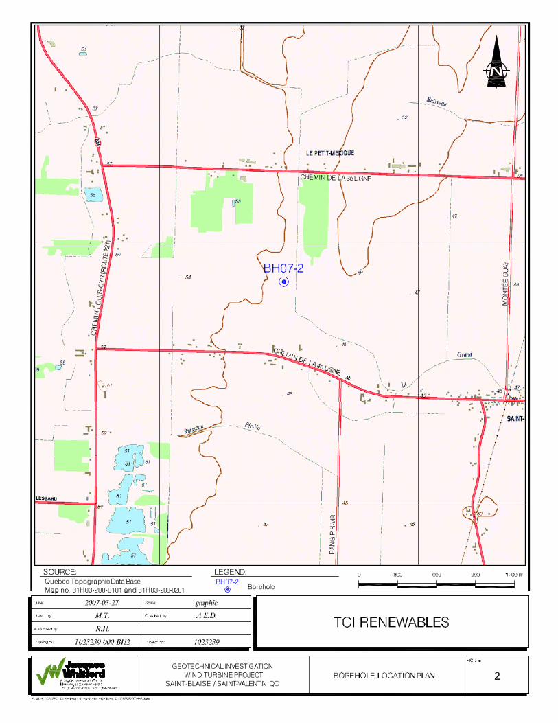
APPENDIX B BH07-2 Lot 305, Chemin de la 4ième Ligne
Appendix B: BH07-2 Lot 305, Chemin de la 4ième Ligne Page 1 of 3
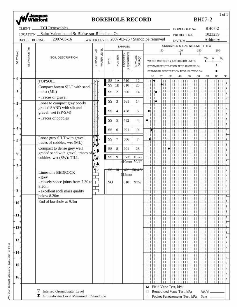
1.0 FINDINGS The subsurface conditions encountered at the Lot 305, Chemin de la 4ème Ligne site location are described in detail on the attached Borehole Record and are summarized in the following paragraphs. An explanation of the symbols and terms used to describe the Borehole Records is also provided.
1.1 Subsurface Information
Borehole BH07-2 was extended to practical refusal at a depth of 7.4 m, then was extended by coring for a total length of 9.32 m. The observed stratigraphy consisted of 0.2 m of topsoil over 4.4 m of loose to compact silt and sand layers extending to 5.3 m below ground surface. Below 5.3 m, the soil deposit consist of a compact to dense till which extends down to bedrock at 7.4m.
The groundwater level could not be measured because the standpipe was removed. Nevertheless the ground water elevation is anticipated to be around 1 m from ground surface. Groundwater levels typically vary with seasonal changes, therefore the groundwater conditions at the time of construction may differ from those encountered during the investigation.
Laboratory testing of representative samples consisted of a sieve analysis in addition to moisture contents testing. The representative sample (sample spoons SS4-SS6) tested for grain size distribution consisted of 79% sand, 16% gravel and 5% silt classifying it as poorly graded sand with gravel (SP). The moisture content ranged from 12% to 28%.
2.0 DISCUSSION AND RECOMMENDATIONS It is understood that a concrete pad type foundation is proposed to support the wind turbine tower. The pad would be octagonal and would be placed at a depth of around 2.4 m. The proposed turbine has a height (at the hub) of 70 m.
2.1 Bearing Capacity
The silt and sand encountered beneath the topsoil becomes loose from 1.8 m to 5.3 m with N values between 4 and 9. These values are considered too low to support the proposed foundation. Based on the soil conditions observed at the site, the following foundation options may be considered.
Option 1:
Remove and replace the loose soils from beneath the wind turbine foundations. Based on Borehole BH07-2, the excavation would extend to 3.0 m below the proposed foundation level and would need to extend laterally 3.0 m beyond the edge of the proposed foundations. The replacement material would consist of structural fill made of MG-112 material (granular soil with little fines) placed and compacted in 300 mm lifts to 95% of Modified Proctor Maximum Dry Density (MPMDD). The following bearing pressures would then be suitable:
Appendix B: BH07-2 Lot 305, Chemin de la 4ième Ligne Page 2 of 3
Geotechnical Resistances Footing Size ULS SLS
6 m Diameter 650 kPa 200 kPa
10 m Diameter 800 kPa 200 kPa
The ULS values incorporate a resistance factor of 0.5 against the nominal ultimate resistance and the SLS values are based on settlements of up to 25 mm.
Option 2:
Advance augered caissons to refusal into the underlying bedrock. It is anticipated that caissons sizes of 0.9 m to 1.2 m in diameter, augered to 0.5 m within the bedrock, would provide geotechnical resistance at ULS at 5000 kPa, which incorporates a resistance factor of 0.4 against the nominal ultimate resistance. The bedrock is generally considered unyielding and therefore a geotechnical resistance at SLS is not considered applicable.
Option 3:
Engage a specialist contractor to dynamically compact the soils, using a large free falling weight, to improve the soils in situ. Dynamic compaction would need to be carried out to at least 4 m beyond the foundation footprint and would need to be designed by the specialist contractor. This option would improve the geotechnical bearing resistance at ULS to at least 500 kPa and at SLS to at least 200 kPa.
Due to the presence of the very permeable sand at BH07-2, which would impose some difficulties on options 1 and 2, option 3 is recommended as the preferred option.
2.2 Construction Considerations
The extent of dewatering required for this project will depend on which option is considered most cost effective. Option 1 will require the removal of close to 3.0 m of potentially high permeable sand. Prior to excavating to remove this material, it would be necessary to dewater the sand using a well point system. This level of effort would suggest that options 2 and 3 may be more feasible.
Should option 2 be carried forward, it will be necessary to case the holes with a temporary or permanent liner to ensure that the sand does not flow into the auger hole.
Option 3, where dynamic compaction is carried out, would require the least strenuous dewatering activities within the very permeable sands present at the site.
Temporary excavations in the overburden shall be sloped at 1 horizontal to 1 vertical from 1.2 m above the base of the excavation and as per the requirements of the provincial “Commission de la santé et sécurité au travail” (CSST). Excavations must be inspected regularly for signs of instability and flattened as required.

Appendix B: BH07-2 Lot 305, Chemin de la 4ième Ligne Page 3 of 3
2.3 Earthquake Considerations
As outlined in the National Building Code of Canada (NBCC), building and its foundations must be designed to resist a minimum earthquake force. In accordance with the new 2005 NBCC, this site is classified as a Class E. The classification would be upgraded to Class D should option 3, dynamic compaction, be carried out.
610610
458
506
1A
JWL-
OLD
102
3239
-LO
GS
.GP
J J
WE
L.G
DT
07-
04-1
7
482
201
506
201
150/410mm
40/115mm
610
561
1B
2
3
4
5
6
7
8
9
10
28
10-7-50/4"
50/4.5"
97%
9
4
SS
SSSS
SS
SS
7
SS
SS
SS
SS
SS
NQ
1220
14
14
6SS
BOREHOLE
DATUM
L
App'd
OR
RQ
D W
TCI RenewablesE
LEV
ATI
ON
(m)
LOCATION
Pocket Penetrometer Test, kPa
CLIENT
1023239BH07-2
(leng
ht/6
10m
m)
STANDARD PENETRATION TEST, BLOWS/0.3m
2007-03-25 / Standpipe removed
50 100 150 200
STR
ATA
PLO
T
PROJECT No.Saint-Valentin and St-Blaise-sur-Richelieu, Qc
Compact brown SILT with sand,moist (ML)
TOPSOIL
Field Vane Test, kPa
Loose to compact grey poorlygraded SAND with silt andgravel, wet (SP-SM)
SOIL DESCRIPTION
WATER LEVEL
Date
N-V
ALU
E
DATES: BORING
- Traces of gravel
End of borehole at 9.3m
Limestone BEDROCK- grey- closely space joints from 7.30 to8.20m- excellent rock mass qualitybelow 8.20m
Compact to dense grey wellgraded sand with gravel, traces ofcobbles, wet (SW): TILL
Loose grey SILT with gravel,traces of cobbles, wet (ML)
- Traces of cobbles
TYP
E
0
1
2
3
4
5
6
7
8
9
10
11
12
13
14
15
16
NU
MB
ER
SAMPLES
Remoulded Vane Test, kPa
No.
DE
PTH
(m)
1 of 1
2007-03-16
WA
TER
LE
VE
L
W W
10 20 30 40 50 60 70 80 90
UNDRAINED SHEAR STRENGTH - kPa
WATER CONTENT & ATTERBERG LIMITS
RE
CO
VE
RY
Arbitrary
DYNAMIC PENETRATION TEST, BLOWS/0.3m
BOREHOLE RECORD BH07-2
P
Groundwater Level Measured in StandpipeInferred Groundwater Level
8170 Montview Rd. suite 100
Mount Royal QC, H4P 2L7 Sieve AnalysisTel: 514 739-0708
Fax: 514 739-8499
Client: TCI Renewables Test Method: ASTM C136Project: Saint Blaise / Saint Valentin, QCProject No: 1023239Material Type: Soils/Aggregrates:Proposed Use: Fill/Granulars:Supplier:Source:Sampled From: Borehole Sample No: BH07-2; SS 4-SS 6Sampled By: Chantal Marcoux Tested By: Steve BernardiDate Sampled: Date Tested: 2-Apr-07
Sample Weight Before Sieve (g) 316.3Sample Weight After Sieve (g) 315.4
% Loss in Sieve 0.28
Weight Amount Cumulativeinches mm Retained(g) Retained(wt %) Amt.Retained(%) Min Max
1 28.00 0.00 0.00 0.00 100.003/4 20.00 0.00 0.00 0.00 100.001/2 14.00 0.00 0.00 0.00 100.003/8 10.00 40.00 12.65 12.65 87.35
4.75 0.187 5.00 10.10 3.19 15.84 84.168 0.0937 2.50 14.50 4.58 20.42 79.5816 0.0469 1.25 24.50 7.75 28.17 71.8330 0.0234 0.630 34.20 10.81 38.98 61.0250 0.0117 0.315 42.10 13.31 52.29 47.71
100 0.0059 0.160 113.10 35.76 88.05 11.95200 0.0029 0.080 22.50 7.11 95.16 4.84
Pan 14.40 4.55 99.72 -Classification of Sample % Gravel: 15.8 % Sand: 79.3 % Silt & Clay: 4.8
Remarks: Poorly graded sand with gravel (SP).
Sieve No. Specifications
Results
Sieve Analysis
% PassingSize of Opening
0.0
10.0
20.0
30.0
40.0
50.0
60.0
70.0
80.0
90.0
100.0
0.01 0.10 1.00 10.00 100.00Grain Size in mm
% P
assi
ng
P:\JOB\1023239 TCI Renewables-Geotech Invest\Lab\Page 2
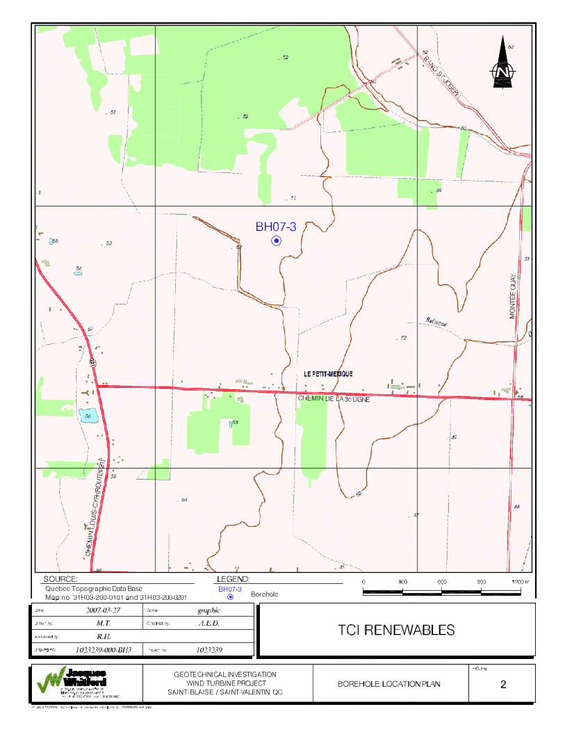
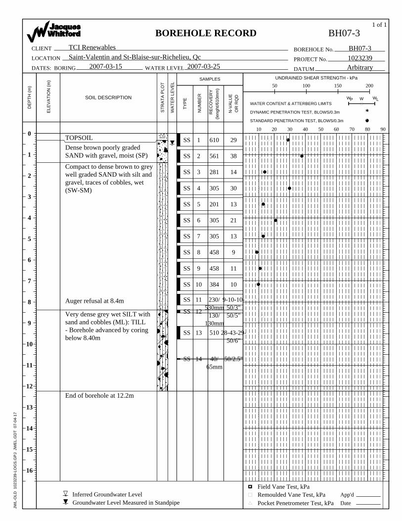
APPENDIX C BH07-3 Lot 292, Chemin de la 3ième Ligne
Appendix C: BH07-3 Lot 292, Chemin de la 3ième Ligne Page 1 of 2
1.0 FINDINGS The subsurface conditions encountered at the Lot 292, Chemin de la 3ième Ligne site location are described in detail on the attached Borehole Record and are summarized in the following paragraphs. An explanation of the symbols and terms used to describe the Borehole Records is also provided.
1.1 Subsurface Information
Borehole BH07-3 was extended to practical refusal to further auger advancement at 8.4 m then extended by coring for a total length of 12.24 m. The observed stratigraphy consisted of 0.35 m of topsoil over 0.4 m of dense brown sand with gravel (SP) layer. Underlying this layer is a generally compact sand extending to 8.4 m below the ground surface. Below is a very dense till consisting primarily of a silt with sand and cobbles.
The groundwater level was measured at a depth of 0.6 m below existing ground surface on March 25, 2007. Groundwater levels typically vary with seasonal changes, therefore the groundwater conditions at the time of construction may differ from those encountered during field-testing.
Laboratory testing of representative samples consisted of a sieve analysis in addition to moisture contents testing. The representative sample (SS4) consisted of 74% sand, 20% gravel and 6 % silt classifying it as well graded sand with silt and gravel (SW-SM). The moisture content ranged from 8 to 17%.
2.0 DISCUSSION AND RECOMMENDATIONS It is understood that concrete pad type foundation is proposed to support the wind turbine tower. The pad is octagonal and will be placed at a depth of around 2.4 m. The turbine has a height (hub) of 70 m.
2.1 Bearing Capacity
The encountered sand had standard penetration test N values ranging from 9 to 30 within the zone of influence of the footing. Based on the observed soil conditions, the following two foundations alternatives may be considered as part of the preliminary design.
Option 1:
Place the foundations on the native soils in their present state. The following geotechnical resistances would apply:
Appendix C: BH07-3 Lot 292, Chemin de la 3ième Ligne Page 2 of 2
Geotechnical Resistances Footing Size ULS SLS
6 m Diameter 500 kPa 100 kPa
10 m Diameter 600 kPa 90 kPa
Option 2:
Engage a specialist contractor to dynamically compact the soils, using a large free falling weight, to improve the soils in situ. Dynamic compaction would need to be carried out to at least 5 m beyond the foundation footprint and would need to be designed by the specialist contractor. This option would improve the geotechnical bearing resistance at ULS to above 700 kPa and at SLS to at least 200 kPa.
2.2 Construction Considerations
Underground water level being near the ground surface, drainage must be provided to control groundwater flow into excavations during construction with an appropriate pump and sump arrangement. Additional site-specific recommendations can be provided at the time of construction.
Temporary excavations in the overburden shall be sloped at 1 horizontal to 1 vertical from 1.2 m above the base of the excavation and as per the requirements of the provincial “Commission de la santé et sécurité au travail” (CSST). Excavations must be inspected regularly for signs of instability and flattened as required.
2.3 Earthquake Considerations
As outlined in the National Building Code of Canada (NBCC), building and its foundations must be designed to resist a minimum earthquake force. In accordance with the new 2005 NBCC, this site is classified as a Class D.
1
JWL-
OLD
102
3239
-LO
GS
.GP
J J
WE
L.G
DT
07-
04-1
7
510
561
610
40/65mm
281
305
201
305
305
458
458
384
230/530mm
130/130mm
14
2
3
4
5
6
7
8
9
10
11
13
12
30
13
21
13
9
11
10
9-10-10-50/3"50/5"
28-43-29-50/6"
29
50/2.5"
SS
SS
14SS
38
SS
SS
SS
SS
SS
SS
SS
SS
SS
SS
SS
2007-03-15 DATUM
OR
RQ
D
BOREHOLEE
LEV
ATI
ON
(m)
DATES: BORING
LW
LOCATION
TCI RenewablesCLIENT
1023239BH07-3
(leng
ht/6
10m
m)
App'd
STANDARD PENETRATION TEST, BLOWS/0.3m
Pocket Penetrometer Test, kPa
50 100 150 200
STR
ATA
PLO
T
PROJECT No.2007-03-25
1 of 1
Saint-Valentin and St-Blaise-sur-Richelieu, Qc
Compact to dense brown to greywell graded SAND with silt andgravel, traces of cobbles, wet(SW-SM)
Auger refusal at 8.4m
Very dense grey wet SILT withsand and cobbles (ML): TILL- Borehole advanced by coringbelow 8.40m
End of borehole at 12.2m
Dense brown poorly gradedSAND with gravel, moist (SP)
TOPSOIL
Field Vane Test, kPaInferred Groundwater Level
DE
PTH
(m)
0
1
2
3
4
5
6
7
8
9
10
11
12
13
14
15
16
NU
MB
ER
SAMPLES
SOIL DESCRIPTION
No.
BH07-3
WA
TER
LE
VE
L
Remoulded Vane Test, kPa
W
WATER LEVEL
Date
N-V
ALU
E
TYP
E
RE
CO
VE
RY
Groundwater Level Measured in Standpipe
P
10 20 30 40 50 60 70 80 90
DYNAMIC PENETRATION TEST, BLOWS/0.3m
WATER CONTENT & ATTERBERG LIMITS
UNDRAINED SHEAR STRENGTH - kPa
BOREHOLE RECORD
W
Arbitrary
8170 Montview Rd. suite 100
Mount Royal QC, H4P 2L7 Sieve AnalysisTel: 514 739-0708
Fax: 514 739-8499
Client: TCI Renewables Test Method: ASTM C136Project: Saint Blaise / Saint Valentin, QCProject No: 1023239Material Type: Soils/Aggregrates:Proposed Use: Fill/Granulars:Supplier:Source:Sampled From: Borehole Sample No: BH07-3; SS 4Sampled By: Chantal Marcoux Tested By: Steve BernardiDate Sampled: Date Tested: 2-Apr-07
Sample Weight Before Sieve (g) 310.0Sample Weight After Sieve (g) 309.7
% Loss in Sieve 0.10
Weight Amount Cumulativeinches mm Retained(g) Retained(wt %) Amt.Retained(%) Min Max
1 28.00 0.00 0.00 0.00 100.003/4 20.00 0.00 0.00 0.00 100.001/2 14.00 0.00 0.00 0.00 100.003/8 10.00 50.40 16.26 16.26 83.74
4.75 0.187 5.00 11.50 3.71 19.97 80.038 0.0937 2.50 14.40 4.65 24.61 75.3916 0.0469 1.25 19.10 6.16 30.77 69.2330 0.0234 0.630 28.80 9.29 40.06 59.9450 0.0117 0.315 38.10 12.29 52.35 47.65
100 0.0059 0.160 92.00 29.68 82.03 17.97200 0.0029 0.080 36.20 11.68 93.71 6.29
Pan 19.20 6.19 99.90 -Classification of Sample % Gravel: 20.0 % Sand: 73.7 % Silt & Clay: 6.3
Remarks: Well-graded sand with silt and gravel (SW-SM).
Sieve No. Specifications
Results
Sieve Analysis
% PassingSize of Opening
0.0
10.0
20.0
30.0
40.0
50.0
60.0
70.0
80.0
90.0
100.0
0.01 0.10 1.00 10.00 100.00Grain Size in mm
% P
assi
ng
P:\JOB\1023239 TCI Renewables-Geotech Invest\Lab\Page 1

APPENDIX D BH07-4 Lot 282, Chemin de la 3ième Ligne
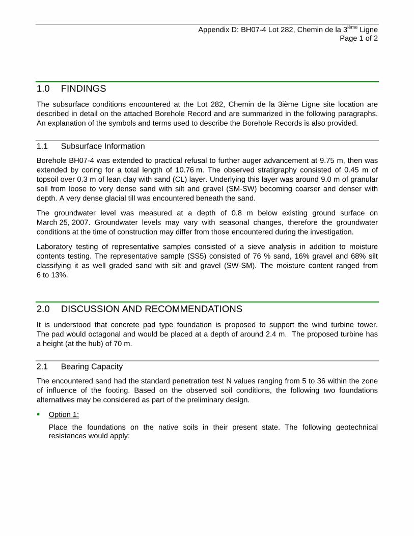
Appendix D: BH07-4 Lot 282, Chemin de la 3ième Ligne Page 1 of 2
1.0 FINDINGS The subsurface conditions encountered at the Lot 282, Chemin de la 3ième Ligne site location are described in detail on the attached Borehole Record and are summarized in the following paragraphs. An explanation of the symbols and terms used to describe the Borehole Records is also provided.
1.1 Subsurface Information
Borehole BH07-4 was extended to practical refusal to further auger advancement at 9.75 m, then was extended by coring for a total length of 10.76 m. The observed stratigraphy consisted of 0.45 m of topsoil over 0.3 m of lean clay with sand (CL) layer. Underlying this layer was around 9.0 m of granular soil from loose to very dense sand with silt and gravel (SM-SW) becoming coarser and denser with depth. A very dense glacial till was encountered beneath the sand.
The groundwater level was measured at a depth of 0.8 m below existing ground surface on March 25, 2007. Groundwater levels may vary with seasonal changes, therefore the groundwater conditions at the time of construction may differ from those encountered during the investigation.
Laboratory testing of representative samples consisted of a sieve analysis in addition to moisture contents testing. The representative sample (SS5) consisted of 76 % sand, 16% gravel and 68% silt classifying it as well graded sand with silt and gravel (SW-SM). The moisture content ranged from 6 to 13%.
2.0 DISCUSSION AND RECOMMENDATIONS It is understood that concrete pad type foundation is proposed to support the wind turbine tower. The pad would octagonal and would be placed at a depth of around 2.4 m. The proposed turbine has a height (at the hub) of 70 m.
2.1 Bearing Capacity
The encountered sand had the standard penetration test N values ranging from 5 to 36 within the zone of influence of the footing. Based on the observed soil conditions, the following two foundations alternatives may be considered as part of the preliminary design.
Option 1:
Place the foundations on the native soils in their present state. The following geotechnical resistances would apply:

Appendix D: BH07-4 Lot 282, Chemin de la 3ième Ligne Page 2 of 2
Geotechnical Resistances Footing Size ULS SLS
6 m Diameter 400 kPa 70 kPa
10 m Diameter 500 kPa 70 kPa
Option 2:
Engage a specialist contractor to dynamically compact the soils, using a large free falling weight, to improve the soils in situ. Dynamic compaction would need to be carried out to at least 5 m beyond the foundation footprint and would need to be designed by the specialist contractor. This option would improve the geotechnical bearing resistance at ULS to above 700 kPa and at SLS to at least 200 kPa.
2.2 Construction Considerations
Underground water level being near the ground surface, drainage must be provided to control groundwater flow into excavations during construction with an appropriate pump and sump arrangement. Additional site-specific recommendations can be provided at the time of construction.
Temporary excavations in the overburden shall be sloped at 1 horizontal to 1 vertical from 1.2 m above the base of the excavation and as per the requirements of the provincial “Commission de la santé et sécurité au travail” (CSST). Excavations must be inspected regularly for signs of instability and flattened as required.
2.3 Earthquake Considerations
As outlined in the National Building Code of Canada (NBCC), building and its foundations must be designed to resist a minimum earthquake force. In accordance with the new 2005 NBCC, this site is classified as a Class D.
>>
1A
JWL-
OLD
102
3239
-LO
GS
.GP
J J
WE
L.G
DT
07-
04-1
7
342
610610
244
409
458
256
384
232
458
305
40/130mm
40/50mm
409
13
1B
2
3
4
5
6
7
8
9
10
12
11
5
7
36
26
34
39
93
50/5"
50/2"
10
SS
SSSS
7
SS 12
SS
SS
SS
SS
SS
SS
SS
SS
SS
18
SS
2007-03-13 DATUM
OR
RQ
D
BOREHOLEE
LEV
ATI
ON
(m)
DATES: BORING
LW
LOCATION
TCI RenewablesCLIENT
1023239BH07-4
(leng
ht/6
10m
m)
App'd
STANDARD PENETRATION TEST, BLOWS/0.3m
Pocket Penetrometer Test, kPa
50 100 150 200
STR
ATA
PLO
T
PROJECT No.2007-03-25
1 of 1
Saint-Valentin and St-Blaise-sur-Richelieu, Qc
- Very dense below 7.50m
Very dense silt and sand withgravel and boulders (ML): TILL
End of borehole at 10.7m
- Cobbles below 6.00m
- Grey and wet with gravel below3.00m
Loose to compact olive grey togrey well graded SAND with silt,moist (SW-SM)
Brown lean CLAY with sand,traces of organics, nearly dry(CL)
Field Vane Test, kPa
TOPSOIL
Inferred Groundwater Level
DE
PTH
(m)
0
1
2
3
4
5
6
7
8
9
10
11
12
13
14
15
16
NU
MB
ER
SAMPLES
SOIL DESCRIPTION
No.
BH07-4
WA
TER
LE
VE
L
Remoulded Vane Test, kPa
WATER LEVEL
Date
N-V
ALU
E
TYP
E
RE
CO
VE
RY
Groundwater Level Measured in Standpipe
PW
BOREHOLE RECORD
Arbitrary
W
10 20 30 40 50 60 70 80 90
UNDRAINED SHEAR STRENGTH - kPa
WATER CONTENT & ATTERBERG LIMITS
DYNAMIC PENETRATION TEST, BLOWS/0.3m
8170 Montview Rd. suite 100
Mount Royal QC, H4P 2L7 Sieve AnalysisTel: 514 739-0708
Fax: 514 739-8499
Client: TCI Renewables Test Method: ASTM C136Project: Saint Blaise / Saint Valentin, QCProject No: 1023239Material Type: Soils/Aggregrates:Proposed Use: Fill/Granulars:Supplier:Source:Sampled From: Borehole Sample No: BH07-4; SS 3-SS 5Sampled By: Chantal Marcoux Tested By: Steve BernardiDate Sampled: Date Tested: 2-Apr-07
Sample Weight Before Sieve (g) 317.5Sample Weight After Sieve (g) 316.8
% Loss in Sieve 0.22
Weight Amount Cumulativeinches mm Retained(g) Retained(wt %) Amt.Retained(%) Min Max
1 28.00 0.00 0.00 0.00 100.003/4 20.00 0.00 0.00 0.00 100.001/2 14.00 0.00 0.00 0.00 100.003/8 10.00 43.40 13.67 13.67 86.33
4.75 0.187 5.00 7.00 2.20 15.87 84.138 0.0937 2.50 15.90 5.01 20.88 79.1216 0.0469 1.25 29.70 9.35 30.24 69.7630 0.0234 0.630 38.30 12.06 42.30 57.7050 0.0117 0.315 46.80 14.74 57.04 42.96
100 0.0059 0.160 52.50 16.54 73.57 26.43200 0.0029 0.080 58.00 18.27 91.84 8.16
Pan 25.20 7.94 99.78 -Classification of Sample % Gravel: 15.9 % Sand: 76.0 % Silt & Clay: 8.2
Remarks: Well graded sand with silt and gravel (SW-SM).
Sieve No. Specifications
Results
Sieve Analysis
% PassingSize of Opening
0.0
10.0
20.0
30.0
40.0
50.0
60.0
70.0
80.0
90.0
100.0
0.01 0.10 1.00 10.00 100.00Grain Size in mm
% P
assi
ng
P:\JOB\1023239 TCI Renewables-Geotech Invest\Lab\Page 3