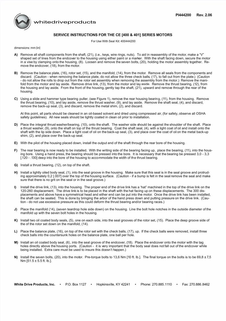
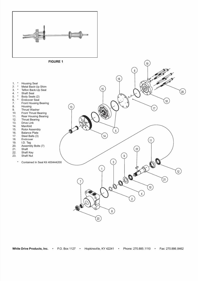
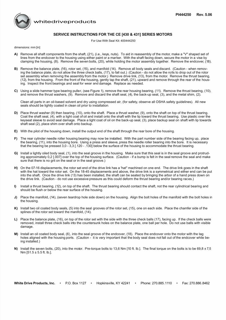
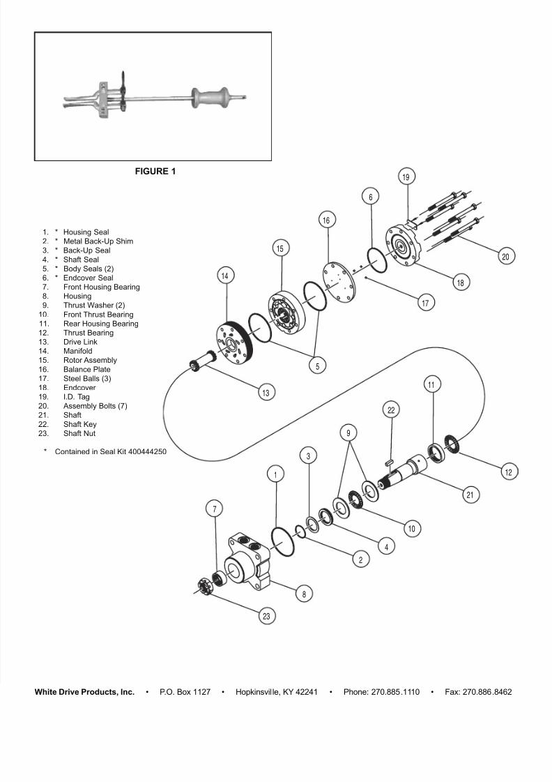
whitedriveproducts White Drive Products, Inc.• P.O. Box 1127 • Hopkinsville, KY 42241 • Phone: 270.885 .1110 • Fax: 270.886.8462 Remove all shaft components from the shaft, (21), (i.e., key s, wire rings, nuts). To aid in reassembly of the motor , make a “V” shaped set of lines from the endcov er to the housing using either paint or a mark er. With the shaft facing down, secure the motor in a vise by clamping onto the housing, (8). Loosen and remove the seven bolts, (20), holding the motor assembly t ogether. Re- move the endcover, (18), from the motor. Remove the balance plate, (16), rotor set, ( 15), and the manifold, (14), from the motor . Remove all seals from the components and discard. (Caution - when removing the balance plate, do not allow the three check balls , (1 7), to fall out from the plate. ) (Caution - do not allow the rolls to drop out from the rotor set assembly when removing the assembly from the motor.) Remove the mani- fold from the motor and lay aside. Remove drive link, (13), from the motor and lay aside. Remove the thrust bearing, (12), from the housing and lay aside. From the front of the housing, gently tap the shaft, (21), upward and remov e through the rear of the housing. Using a slide and hammer type bearing puller, (see Figure 1), remov e the rear housing bearin g, (1 1), from the housing. Remove the thrust bearing, (10), and lay aside, remove the thrust washer, (9), and lay aside. Remove the shaft seal, (4), and discard, remove the back-up seal, (3), and discard, remove the metal shim, (2), and discard. At this point, all parts should be cleaned in an oil-based solvent and dried using compressed air, (for safety, observe all OSHA safety guidelines). All new seals should be lightly coated in clean oil prior to installation. Place the integral thrust washer/bearing, (10), onto the shaft. The washer side s hould be against the shoulder of the shaft. Place a thrust washer, (9), onto the shaft on top of the thrust bearing. Coat the shaft seal, (4), with a light coat of oil and install onto the shaft with the lip side down. Place a light coat of oil on the back-up seal, (3), and place over the coat of oil on the metal back-up shim, (2), and place over the back-up seal. With the pilot of the housing placed down, install the output end of the shaft through the rear bore of the housing. The rear bearing is now ready to be installed. With the writing side of the bearing facing up, place the bearing, (1 1), into the hous- ing bore. Using a hand press, the bearing should be pressed into the bore. It is necessary that the bearing be pressed 3,0 - 3,3 [. 120 - .1 30] dee p into the bore of the housing to acco mmodate the width of th e thrust bearing. Install a thrust bearing, (12), on top of the shaft. Install a lightly oiled body seal, (1), into the seal groove in the housing. Make sure that this seal is in the seal groove and protrud- ing approximately 0,2 [.007] over the top of the housing surface. (Caution - if a bump is felt in the seal remove the seal and make sure that there is no grit on the seal or in the seal groove.) Install the drive link, (13), into the housing. The proper end of the dr ive link has a ‘hat” machined in the top of the drive link on the 120-260 displacement. The drive link is to be placed in the shaft with the hat facing up on these displacements. The 300 dis- placements and above have a symmetrical head and either end can be put into the motor . Once the drive link has been installed, the shaft can be seated. This is done by bringing the arbor of the hand press down and putting pressure on the drive link. (Cau- tion - do not use excessive pressure as this could deform the thrust bearing and/or bearing races.) Place the manifold (1 4), (seven teardrop hole side down) on the housing. Line the bolt hole notches in the outside diameter of the manifold up with the seven bolt holes in the housing. Install two oil coated body seals, (5) , one on each side, into the seal grooves of the rotor set, (15). Place the deep groove side of the of the rotor set down on the manifold, (14). Place the balance plate, (16), on top of the rotor set with the check balls, (17), up. If the check balls were removed, install three check balls into the countersunk holes on the balance plate, one ball per hole. Install an oil coated body seal, (6) , into the seal groove of the endcover, ( 18). Place the endcover onto the motor with the tag holes directly above the housing ports. (Caution - it is v ery important that the body seal does not fall out of the endcover while being installed. Extra care must be used to insure this doesn’t h appen.) Install the seven bolts, (20), into the mot or. Pre-torque bolts to 13,6 Nm [1 0 ft. lb.]. The final torque on the bolts is to be 69,8 ± 7 ,5 Nm [51.5 ± 5.5 ft. lb.]. SERVICE INSTRUCTIONS FOR THE CE [400 & 401] SERIES MOTORS PI444200 Rev. 2.06 For Use With Seal Kit: 400444200 A) B) C) D) E) F) G) H) I) J) K) L) M) N) dimensions: mm [in]