Embed Size (px)
Citation preview
CONNECTEURS 1977
Edition 10 / 02
1977 CONNECTORS
Amphenol Air LB
SYSTÈMES DE CONNEXIONS ÉLECTRIQUES ET ÉLECTRONIQUESELECTRIC AND ELECTRONIC CONNECTION SYSTEMS
1
SOMMAIRETABLE OF CONTENTS
PRÉSENTATION
ACCOUPLEMENT - DÉTROMPAGE
ACCESSOIRE - PERÇAGE DE PANNEAU
CARACTÉRISTIQUES TECHNIQUES
SYSTÈME DE RÉFÉRENCE
CONTACTS
OUTILS CONNECTEURS 1977
DÉTROMPEURS DACCOUPLEMENT
CONNECTEUR FEMELLE
CONNECTEUR MÂLE
PROCEDURE DE CABLAGE
PRESENTATION
COUPLING - POLARIZING
ACCESSORY - PANEL CUTOUT
TECHNICAL DATA
PART NUMBER SYSTEM
CONTACTS
1977 CONNECTOR TOOLS
MATING POLARIZER
FEMALE CONNECOR
MALE CONNECTOR
WIRING INSTRUCTION
2
3
4
5
6
7
8
9
10
11
12-13
2
PRÉSENTATIONPRESENTATION
F1
M1
Détrompeur femelleFemale polarizer
b
P
Ø 7 (.275 dia)
1,6 max (.063 maxi)
F2
S
a
Détrompeur mâleMale polarizer
Connecteur mâleMale connector
M2
Contact MâlePin contact
Connecteur femelleFemale connector
Contact femelleSocket contact
Serre-câblesCable clamps
Clip de rétentionRetention clip
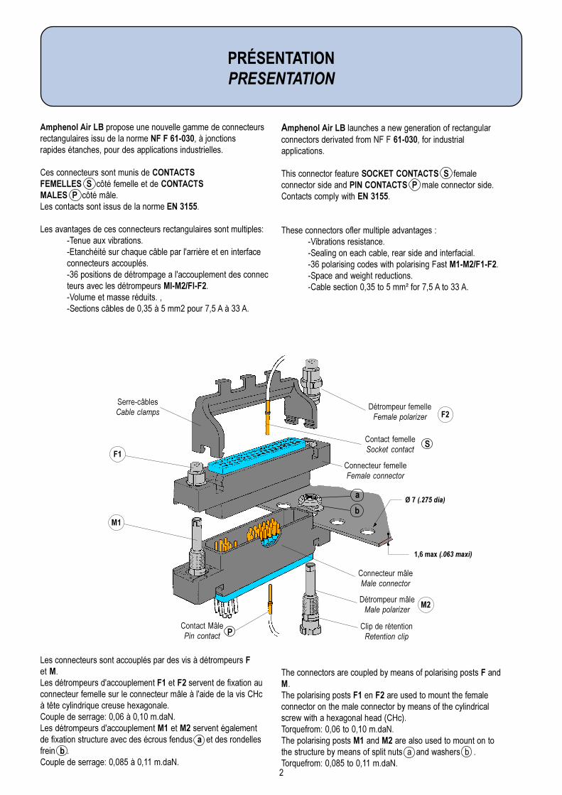
Amphenol Air LB propose une nouvelle gamme de connecteursrectangulaires issu de la norme NF F 61-030, à jonctionsrapides étanches, pour des applications industrielles.
Ces connecteurs sont munis de CONTACTSFEMELLES S côté femelle et de CONTACTSMALES P côté mâle.Les contacts sont issus de la norme EN 3155.
Les avantages de ces connecteurs rectangulaires sont multiples:-Tenue aux vibrations.-Etanchéité sur chaque câble par l'arrière et en interfaceconnecteurs accouplés.-36 positions de détrompage a l'accouplement des connecteurs avec les détrompeurs MI-M2/FI-F2.-Volume et masse réduits. ,-Sections câbles de 0,35 à 5 mm2 pour 7,5 A à 33 A.
Les connecteurs sont accouplés par des vis à détrompeurs Fet M.Les détrompeurs d'accouplement F1 et F2 servent de fixation auconnecteur femelle sur le connecteur mâle à l'aide de la vis CHcà tête cylindrique creuse hexagonale.Couple de serrage: 0,06 à 0,10 m.daN.Les détrompeurs d'accouplement M1 et M2 servent égalementde fixation structure avec des écrous fendus a et des rondellesfrein b .Couple de serrage: 0,085 à 0,11 m.daN.
Amphenol Air LB launches a new generation of rectangularconnectors derivated from NF F 61-030, for industrialapplications.
This connector feature SOCKET CONTACTS S femaleconnector side and PIN CONTACTS P male connector side.Contacts comply with EN 3155.
These connectors ofler multiple advantages :-Vibrations resistance.-Sealing on each cable, rear side and interfacial.-36 polarising codes with polarising Fast M1-M2/F1-F2.-Space and weight reductions.-Cable section 0,35 to 5 mm² for 7,5 A to 33 A.
The connectors are coupled by means of polarising posts F andM.The polarising posts F1 en F2 are used to mount the femaleconnector on the male connector by means of the cylindricalscrew with a hexagonal head (CHc).Torquefrom: 0,06 to 0,10 m.daN.The polarising posts M1 and M2 are also used to mount on tothe structure by means of split nuts a and washers b .Torquefrom: 0,085 to 0,11 m.daN.
3
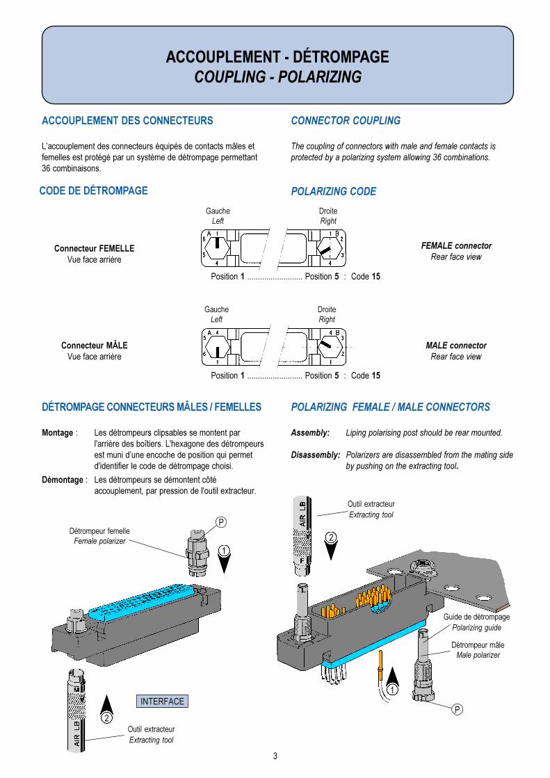
CONNECTOR COUPLING
The coupling of connectors with male and female contacts isprotected by a polarizing system allowing 36 combinations.
POLARIZING CODE
POLARIZING FEMALE / MALE CONNECTORS
Assembly: Liping polarising post should be rear mounted.
Disassembly: Polarizers are disassembled from the mating sideby pushing on the extracting tool.
DÉTROMPAGE CONNECTEURS MÂLES / FEMELLES
Montage : Les détrompeurs clipsables se montent parl'arrière des boîtiers. L'hexagone des détrompeursest muni dune encoche de position qui permetd'identifier le code de détrompage choisi.
Démontage : Les détrompeurs se démontent côtéaccouplement, par pression de l'outil extracteur.
ACCOUPLEMENT DES CONNECTEURS
Laccouplement des connecteurs équipés de contacts mâles etfemelles est protégé par un système de détrompage permettant36 combinaisons.
ACCOUPLEMENT - DÉTROMPAGECOUPLING - POLARIZING
INTERFACE
2
1
Outil extracteurExtracting tool
Détrompeur femelleFemale polarizer
P
Outil extracteurExtracting tool
2
1
Guide de détrompagePolarizing guide
Détrompeur mâleMale polarizer
P
CODE DE DÉTROMPAGE
Connecteur FEMELLEVue face arrière
FEMALE connectorRear face view
GaucheLeft
DroiteRight
Connecteur MÂLEVue face arrière
GaucheLeft
DroiteRight
Position 1 .......................... Position 5 : Code 15
Position 1 .......................... Position 5 : Code 15
MALE connectorRear face view
4
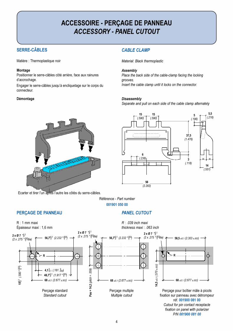
CABLE CLAMP
Material: Black thermoplastic
AssemblyPlace the back side of the cable-clamp facing the lockinggrooves.Insert the cable clamp until it locks on the connector.
DisassemblySeparate and pull on each side of the cable clamp alternately
SERRE-CÂBLES
Matière : Thermoplastique noir
MontagePositionner le serre-câbles côté arrière, face aux rainuresdaccrochage.
Engager le serre-câbles jusquà encliquetage sur le corps duconnecteur.
PERÇAGE DE PANNEAU
R : 1 mm maxiÉpaisseur maxi : 1,6 mm
PANEL CUTOUT
R : .039 inch maxithickness maxi : .063 inch
Perçage standardStandard cutout
Perçage multipleMultiple cutout
Perçage pour boîtier mâle à picotsfixation sur panneau avec détrompeur
réf. 001900 081 00Cutout for pin contact receptaclefixation on panel with polarizer
P/N 001900 081 00
ACCESSOIRE - PERÇAGE DE PANNEAUACCESSORY - PANEL CUTOUT
15(.590)
15(.590)
37,5(1.476)
5,5(.216)
5(.196)
6(.236)
14(.551)
58(2.283)
3(.118)
68 ±0,1 (2.677 ±.003)
56,7 (2.232 )
15
(.5
90
)
Pas
= 14
,2 (p
itch
= .5
59)
+0,1 0
+.003 0
48,7 (1.917 )+0,1 0
+.003 0
+0,1
0+.
003
0 4,1 (.161 ) 0- 0,1
0-.003
68 ±0,1 (2.677 ±.003) 68 ±0,1 (2.677 ±.003)
56,7 (2.232 )+0,1 0
+.003 0 58,5 ±0,1 (2.303 ±.003)
14,5
±0,
1 (.5
70 ±
.003
)
2 x Ø 7(2 x .275 dia)
+0,1 0+.003
0
2 x Ø 7(2 x .275 dia)
+0,1 0+.003
02 x Ø 7(2 x .275 dia)
+0,1 0+.003
0
R R
Démontage
Ecarter et tirer lun après lautre les côtés du serre-câbles.
Référence - Part number
001901 050 00
5
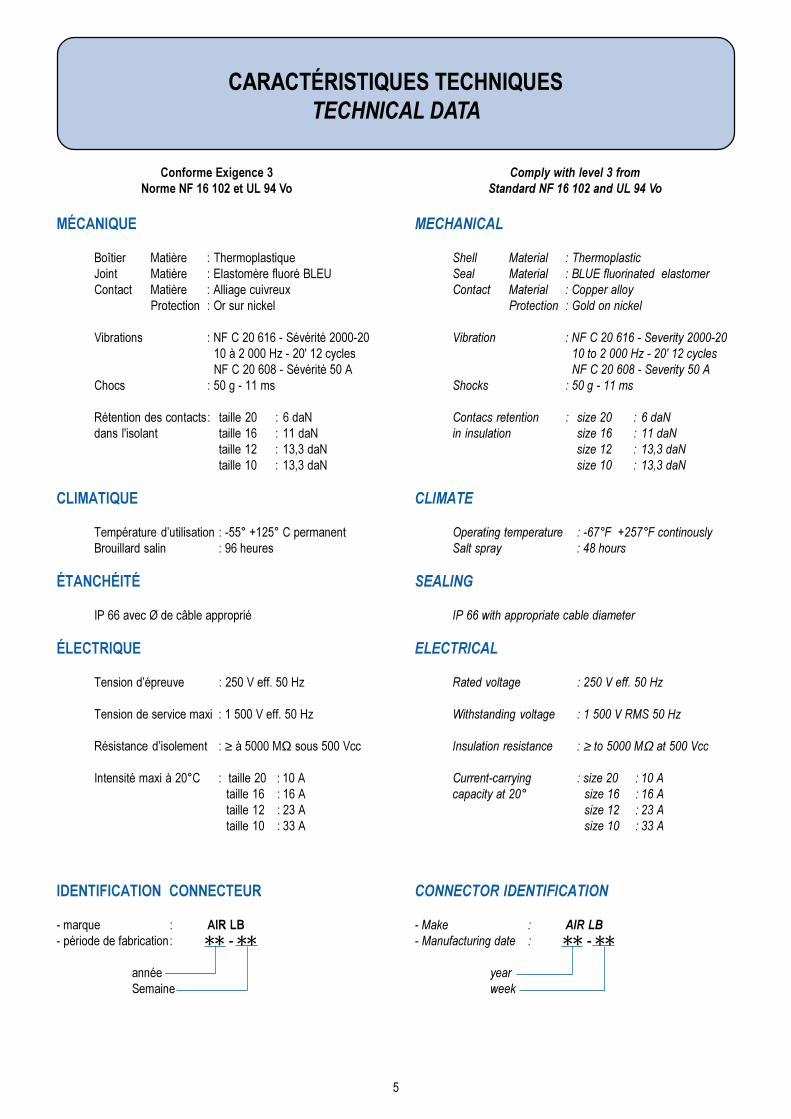
MECHANICAL
Shell Material : ThermoplasticSeal Material : BLUE fluorinated elastomerContact Material : Copper alloy
Protection : Gold on nickel
Vibration : NF C 20 616 - Severity 2000-20 10 to 2 000 Hz - 20' 12 cycles NF C 20 608 - Severity 50 A
Shocks : 50 g - 11 ms
Contacs retention : size 20 : 6 daNin insulation size 16 : 11 daN
size 12 : 13,3 daNsize 10 : 13,3 daN
CLIMATE
Operating temperature : -67°F +257°F continouslySalt spray : 48 hours
SEALING
IP 66 with appropriate cable diameter
ELECTRICAL
Rated voltage : 250 V eff. 50 Hz
Withstanding voltage : 1 500 V RMS 50 Hz
Insulation resistance : ≥ to 5000 MΩ at 500 Vcc
Current-carrying : size 20 : 10 Acapacity at 20° size 16 : 16 A
size 12 : 23 Asize 10 : 33 A
CONNECTOR IDENTIFICATION
- Make : AIR LB- Manufacturing date : QQ - QQ
yearweek
MÉCANIQUE
Boîtier Matière : ThermoplastiqueJoint Matière : Elastomère fluoré BLEUContact Matière : Alliage cuivreux
Protection : Or sur nickel
Vibrations : NF C 20 616 - Sévérité 2000-20 10 à 2 000 Hz - 20' 12 cycles NF C 20 608 - Sévérité 50 A
Chocs : 50 g - 11 ms
Rétention des contacts: taille 20 : 6 daNdans l'isolant taille 16 : 11 daN
taille 12 : 13,3 daNtaille 10 : 13,3 daN
CLIMATIQUE
Température dutilisation : -55° +125° C permanentBrouillard salin : 96 heures
ÉTANCHÉITÉ
IP 66 avec Ø de câble approprié
ÉLECTRIQUE
Tension dépreuve : 250 V eff. 50 Hz
Tension de service maxi : 1 500 V eff. 50 Hz
Résistance disolement : ≥ à 5000 MΩ sous 500 Vcc
Intensité maxi à 20°C : taille 20 : 10 Ataille 16 : 16 Ataille 12 : 23 Ataille 10 : 33 A
IDENTIFICATION CONNECTEUR
- marque : AIR LB- période de fabrication: QQ - QQ
annéeSemaine
CARACTÉRISTIQUES TECHNIQUESTECHNICAL DATA
Conforme Exigence 3Norme NF 16 102 et UL 94 Vo
Comply with level 3 fromStandard NF 16 102 and UL 94 Vo
6
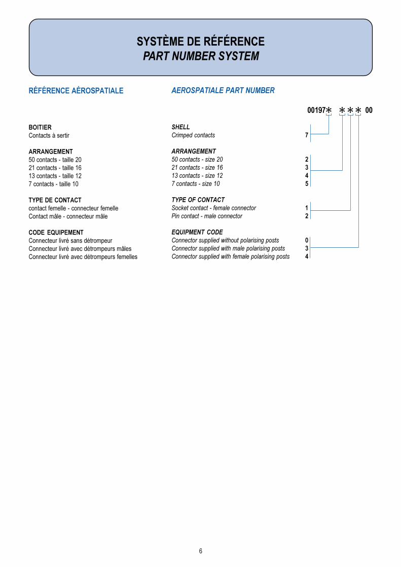
SYSTÈME DE RÉFÉRENCEPART NUMBER SYSTEM
AEROSPATIALE PART NUMBER
SHELLCrimped contacts 7
ARRANGEMENT50 contacts - size 20 221 contacts - size 16 313 contacts - size 12 47 contacts - size 10 5
TYPE OF CONTACTSocket contact - female connector 1Pin contact - male connector 2
EQUIPMENT CODEConnector supplied without polarising posts 0Connector supplied with male polarising posts 3Connector supplied with female polarising posts 4
RÉFÉRENCE AÉROSPATIALE
00197Q Q Q Q 00
BOITIERContacts à sertir
ARRANGEMENT50 contacts - taille 2021 contacts - taille 1613 contacts - taille 127 contacts - taille 10
TYPE DE CONTACTcontact femelle - connecteur femelleContact mâle - connecteur mâle
CODE EQUIPEMENTConnecteur livré sans détrompeurConnecteur livré avec détrompeurs mâlesConnecteur livré avec détrompeurs femelles
7
elliaTeziS
rueluoCruoloC
nolyN)C°571+°55-()F°743+F°76-(
%gessaM%gthgieW
02 /eguoR deR 24012901100 5
61 /uelB eulB 04003901100 21
21 /enuaJ wolleY 14004901100 82
01 /treV neerG 14006901100 75
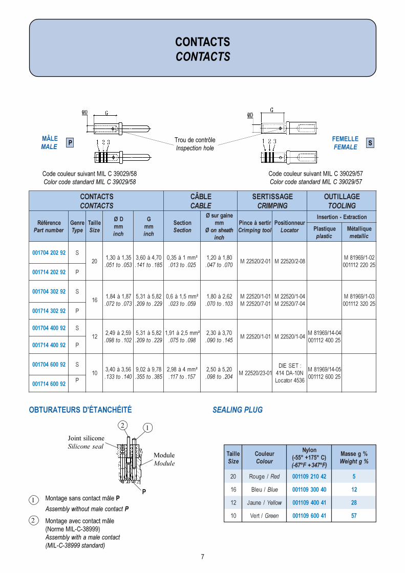
CONTACTSCONTACTS
Trou de contrôleInspection hole
MÂLEMALE
P FEMELLEFEMALE
S
2
1
12
Joint siliconeSilicone seal
ModuleModule
OBTURATEURS D'ÉTANCHÉITÉ SEALING PLUG
Code couleur suivant MIL C 39029/58Color code standard MIL C 39029/58
Code couleur suivant MIL C 39029/57Color code standard MIL C 39029/57
STCATNOCSTCATNOC
ELBÂCELBAC
EGASSITRESGNIPMIRC
EGALLITUOGNILOOT
ecneréféRrebmuntraP
erneGepyT
elliaTeziS
DØmmhcni
Gmmhcni
noitceSnoitceS
eniagrusØmm
htaehsnoØhcni
ritresàecniPlootgnipmirC
ruennoitisoProtacoL
noitcartxE-noitresnI
euqitsalPcitsalp
euqillatéMcillatem
29202407100 S02
53,1à03,1350.ot150.
07,4à06,3581.ot141.
²mm1à53,0520.ot310.
08,1à02,1070.ot740.
10-2/02522M 80-2/02522M20-1/96918M52022211100
29202417100 P
29203407100 S61
78,1à48,1370.ot270.
28,5à13,5922.ot902.
²mm5,1à6,0950.ot320.
26,2à08,1301.ot070.
10-1/02522M10-7/02522M
40-1/02522M40-7/02522M
30-1/96918M52023211100
29203417100 P
29004407100 S21
95,2à94,2201.ot890.
28,5à13,5922.ot902.
²mm5,2à19,1890.ot570.
07,3à03,2541.ot090.
10-1/02522M 40-1/02522M40-41/96918M52004211100
29004417100 P
29006407100 S01
65,3à04,3041.ot331.
87,9à20,9583.ot553.
²mm4à89,2751.ot711.
02,5à05,2402.ot890.
10-32/02522M:TESEIDN01-AD4146354rotacoL
50-41/96918M52006211100
29006417100P
PMontage sans contact mâle P
Assembly without male contact P
Montage avec contact mâle(Norme MIL-C-38999)Assembly with a male contact(MIL-C-38999 standard)
8
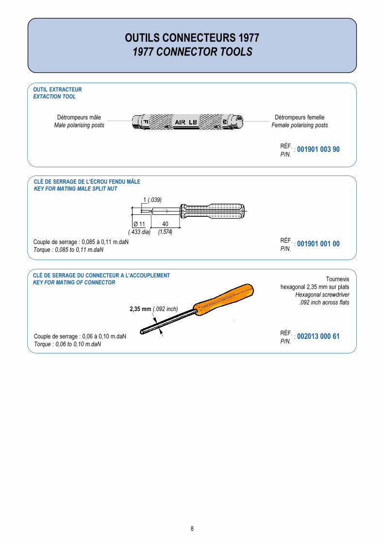
Couple de serrage : 0,085 à 0,11 m.daNTorque : 0,085 to 0,11 m.daN
OUTILS CONNECTEURS 19771977 CONNECTOR TOOLS
Détrompeurs femelleFemale polarising posts
Détrompeurs mâleMale polarising posts
RÉF. : 001901 003 90P/N.
OUTIL EXTRACTEUREXTACTION TOOL
CLÉ DE SERRAGE DE L'ÉCROU FENDU MÂLEKEY FOR MATING MALE SPLIT NUT
CLÉ DE SERRAGE DU CONNECTEUR A L'ACCOUPLEMENTKEY FOR MATING OF CONNECTOR
2,35 mm (.092 inch)
RÉF. : 001901 001 00P/N.
RÉF. : 002013 000 61P/N.
Couple de serrage : 0,06 à 0,10 m.daNTorque : 0,06 to 0,10 m.daN
Tournevishexagonal 2,35 mm sur plats
Hexagonal screwdriver.092 inch across flats
1 (.039)
40(1.574)
Ø 11(.433 dia)
9
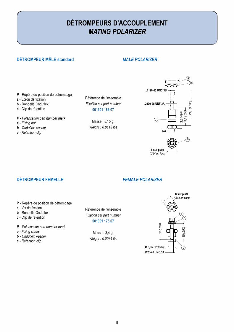
DÉTROMPEURS D'ACCOUPLEMENTMATING POLARIZER
DÉTROMPEUR MÂLE standard MALE POLARIZER
DÉTROMPEUR FEMELLE FEMALE POLARIZER
Référence de l'ensemble
Fixation set part number
001901 186 07
Masse : 5,15 g.
Weight : 0.0113 lbs
P - Repère de position de détrompagea - Ecrou de fixationb - Rondelle Onduflexc - Clip de rétention
P - Polarisation part number marka - Fixing nutb - Onduflex washerc - Retention clip
Référence de l'ensemble
Fixation set part number
001901 176 07
Masse : 3,4 g.
Weight : 0.0074 lbs
P - Repère de position de détrompagea - Vis de fixationb - Rondelle Onduflexc - Clip de rétention
P - Polarisation part number marka - Fixing screwb - Onduflex washerc - Retention clip
8 sur plats(.314 on flats)
.2500-28 UNF 3A
.1120-40 UNC 3B
M4
2,5
(.098
)14
,1 (.
555)
27,6
(1.0
86)
8 sur plats(.314 on flats)
.1120-40 UNC 3A
18 (.
708)
15 (.
590)
Ø 6,35 (.250 dia)
ab
c
ab
c
P
10
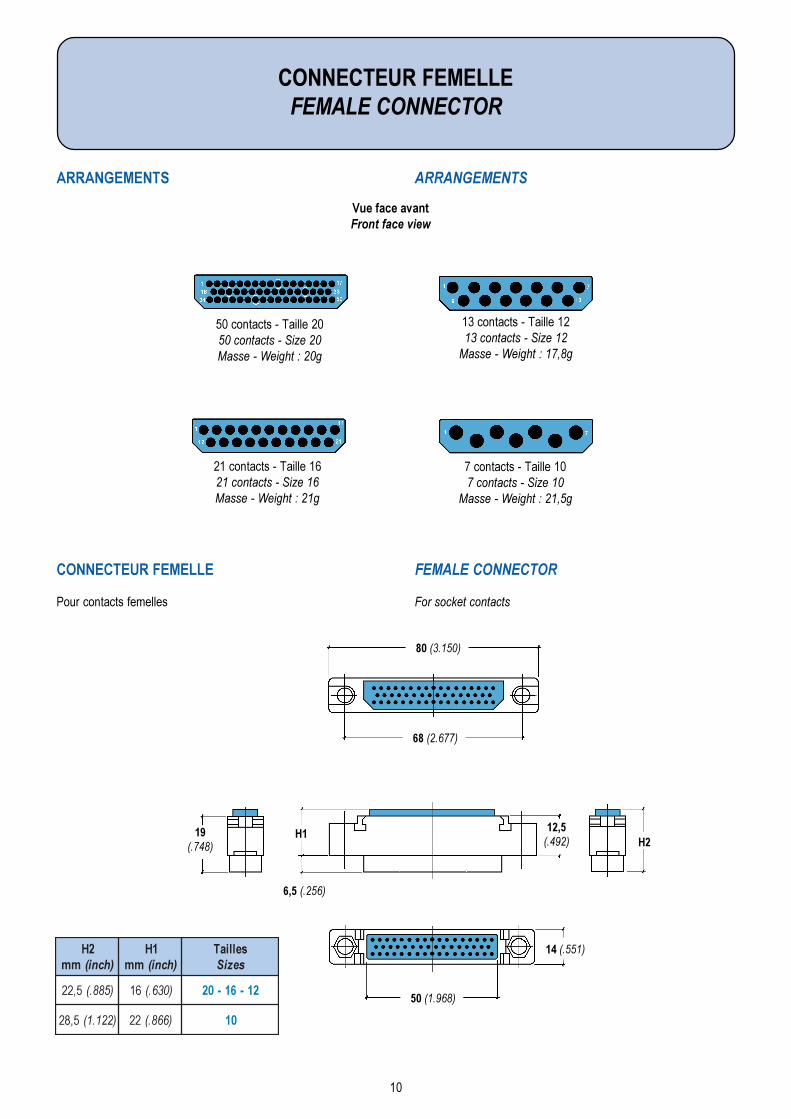
Vue face avantFront face view
Pour contacts femelles
19H1
H2
CONNECTEUR FEMELLEFEMALE CONNECTOR
ARRANGEMENTS ARRANGEMENTS
50 contacts - Taille 2050 contacts - Size 20Masse - Weight : 20g
CONNECTEUR FEMELLE FEMALE CONNECTOR
21 contacts - Taille 1621 contacts - Size 16Masse - Weight : 21g
13 contacts - Taille 1213 contacts - Size 12
Masse - Weight : 17,8g
7 contacts - Taille 107 contacts - Size 10
Masse - Weight : 21,5g
80 (3.150)
68 (2.677)
50 (1.968)
14 (.551)
12,5(.492)
6,5 (.256)
19(.748)
For socket contacts
2Hmm )hcni(
1Hmm )hcni(
selliaTseziS
5,22 )588.( 61 )036.( 21-61-02
5,82 )221.1( 22 )668.( 01
11
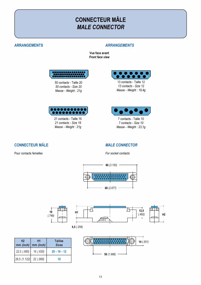
Vue face avantFront face view
Pour contacts femelles
19H1
H2
CONNECTEUR MÂLEMALE CONNECTOR
ARRANGEMENTS ARRANGEMENTS
50 contacts - Taille 2050 contacts - Size 20Masse - Weight : 21g
CONNECTEUR MÂLE MALE CONNECTOR
21 contacts - Taille 1621 contacts - Size 16Masse - Weight : 21g
13 contacts - Taille 1213 contacts - Size 12
Masse - Weight : 19,4g
7 contacts - Taille 107 contacts - Size 10
Masse - Weight : 23,1g
80 (3.150)
68 (2.677)
50 (1.968)
14 (.551)
12,5(.492)
6,5 (.256)
19(.748)
For socket contacts
2Hmm )hcni(
1Hmm )hcni(
selliaTseziS
5,22 )588.( 61 )036.( 21-61-02
5,82 )221.1( 22 )668.( 01
12
PROCÉDURE DE CÂBLAGEWIRING INSTRUCTIONS
PositionneurLocator
21
1
Pince à sertirCrimping tool
4
2 Côté couleurColour side
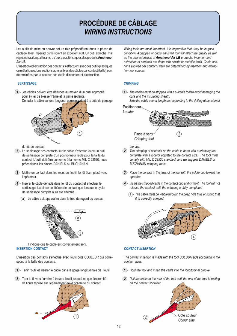
the cup.2 - The crimping of contacts on the cable is done with a crimping tool
complete with a locator adjusted to the contact size. The tool mustcomply with MIL C 22520 standard, and we suggest DANIELS orBUCHANAN crimping tools.
3 - Place the contact in the jaws of the tool with the solder cup toward theoperator.
4 - Insert the stripped cable in the contact cup and crimp it. The tool will notrelease the contact until the crimping is fully completed
a - The cable must be visible through the peep hole thus ensuring thatit is correctly crimped.
Wiring tools are most important. It is imperative that they be in goodcondition. A chipped or badly adjusted tool will affect the quality as wellas the characteristics of Amphenol Air LB products. Insertion andextraction of contacts are done with plastic or metallic tools. Cable sec-tions allowed per contact (size) are determined by insertion and extrac-tion tool colours.
CRIMPING
1 - The cables must be stripped with a suitable tool to avoid damaging thecore and the insulating sheath.Strip the cable over a length corresponding to the drilling dimension of
du fût de contact.2 - Le sertissage des contacts sur le câble seffectue avec un outil
de sertissage complété dun positionneur réglé pour la taille ducontact. Loutil doit être conforme à la norme MIL C 22520, nouspréconisons les pinces DANIELS ou BUCHANAN.
3 - Mettre un contact dans les mors de loutil, le fût étant placé verslopérateur.
4 - Insérer le câble dénudé dans le fût du contact et effectuer lesertissage. La pince ne libérera le contact que lorsque le cyclede sertissage complet aura été effectué.
a - Le câble doit apparaître dans le trou de regard du contact,
il indique que le câble est correctement serti.INSERTION CONTACT
L'insertion des contacts s'effectue avec l'outil côté COULEUR qui corre-spond à la taille des contacts.
1 - Tenir loutil et insérer le câble dans la gorge longitudinale de l'outil.
2 - Tirer le fil vers larrière à travers loutil jusquà ce que lextrémitéde loutil repose sur lépaulement de la collerette du contact.
Les outils de mise en oeuvre ont un rôle prépondérant dans la phase decâblage. Il est impératif quils soient en excellent état. Un outil ébréché, malréglé, nuira à la qualité ainsi quaux caractéristiques des produits AmphenolAir LB.L'insertion et l'extraction des contacts s'effectuent avec des outils plastiquesou métalliques. Les sections admissibles des câbles par contact (taille) sontdéterminées par la couleur des outils d'insertion et d'extraction.
SERTISSAGE
1 - Les câbles doivent être dénudés au moyen dun outil appropriépour éviter de blesser lâme et la gaine isolante.Dénuder le câble sur une longueur correspondant à la côte de perçage
CONTACT INSERTION
The contact insertion is made with the tool COLOUR side according to thecontact sizes.
1 - Hold the tool and insert the cable into the longitudinal groove.
2 - Pull the cable to the rear of the tool until the end of the tool is restingon the contact shoulder.
3
a
13
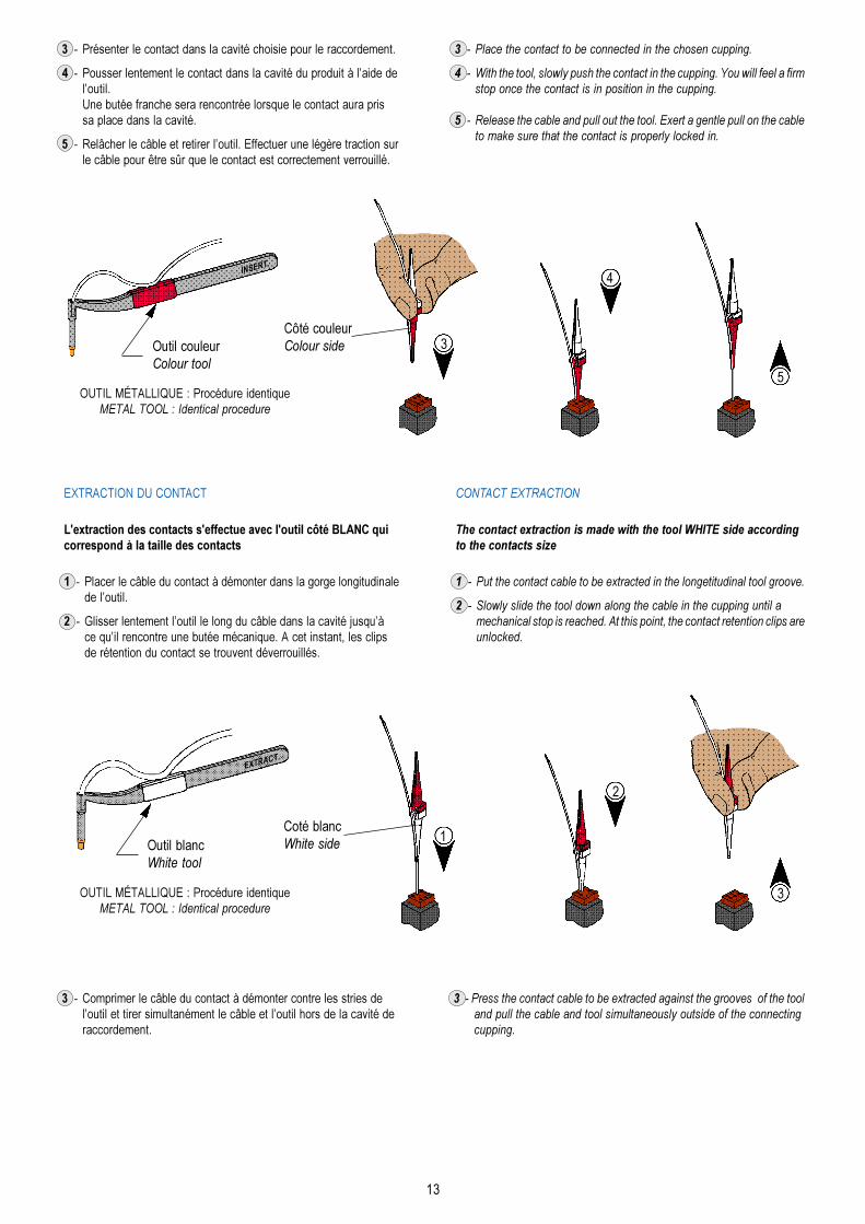
3 - Place the contact to be connected in the chosen cupping.
4 - With the tool, slowly push the contact in the cupping. You will feel a firmstop once the contact is in position in the cupping.
5 - Release the cable and pull out the tool. Exert a gentle pull on the cableto make sure that the contact is properly locked in.
3 - Présenter le contact dans la cavité choisie pour le raccordement.
4 - Pousser lentement le contact dans la cavité du produit à laide deloutil.Une butée franche sera rencontrée lorsque le contact aura prissa place dans la cavité.
5 - Relâcher le câble et retirer loutil. Effectuer une légère traction surle câble pour être sûr que le contact est correctement verrouillé.
Outil blancWhite tool
OUTIL MÉTALLIQUE : Procédure identiqueMETAL TOOL : Identical procedure
3
2
1Coté blancWhite side
EXTRACT.
Outil couleurColour tool
OUTIL MÉTALLIQUE : Procédure identiqueMETAL TOOL : Identical procedure
4
5
Côté couleurColour side
INSERT.
EXTRACTION DU CONTACT
L'extraction des contacts s'effectue avec l'outil côté BLANC quicorrespond à la taille des contacts
1 - Placer le câble du contact à démonter dans la gorge longitudinalede loutil.
2 - Glisser lentement loutil le long du câble dans la cavité jusquàce quil rencontre une butée mécanique. A cet instant, les clipsde rétention du contact se trouvent déverrouillés.
CONTACT EXTRACTION
The contact extraction is made with the tool WHITE side accordingto the contacts size
1 - Put the contact cable to be extracted in the longetitudinal tool groove.
2 - Slowly slide the tool down along the cable in the cupping until amechanical stop is reached. At this point, the contact retention clips areunlocked.
3 - Press the contact cable to be extracted against the grooves of the tooland pull the cable and tool simultaneously outside of the connectingcupping.
3 - Comprimer le câble du contact à démonter contre les stries deloutil et tirer simultanément le câble et loutil hors de la cavité deraccordement.
3

Amphenol
Ce document nest pas contractuel. Les informations contenues dans ce catalogue sont susceptibles dévolution.Amphenol Air LB se réserve le droit de procéder à des modifications sans préavis. Pour tout renseignement complémentaire, nous consulter.
This document is not a contractual document. The information included in this catalogue is subject to changes.Amphenol Air LB reserves the right to proceed with modifications without prior notice. For any additional information, do not hesitate to contact us.
Amphenol Air LBDirection des Ventes / Sales officeImmeuble le Doublon - 11, Avenue Dubonnet
92407 COURBEVOIE Cedex - FranceTél. : (33) 01 49 05 30 00 - Fax : (33) 01 49 05 30 10
D.E.RR & D
Centre de ProductionProduction Center
Amphenol Air LB GmbH
10, Rue Champ Raymond08110 CARIGNAN - FRANCE
29, Voie dYvois08110 BLAGNY - FRANCE
CA
RIG
NA
N
CA
NA
DA
Amphenol Air LB North America Inc.
295 Kesmark - DOLLARD-DES-ORMEAUXH9B 3J1 QUEBEC
Tél. : (1) 514 421-2153 - Fax : (1) 514 421-3408Web : http://www.amphenol-airlb.com
E-mail : [email protected]
CA
NA
DA
Distributeur / Distributor
ROYAUME-UNI / UNITED KINGDOMChannel Electric Equipment Ltd.
Bath Road - THATCHAM Near NewburyBERKSHIRE RG 18 3 ST - Royaume-Uni
Tél. : (44) 1 635 864 866Fax : (44) 1 635 869 178
AL
LE
MA
GN
E
Am Kleinbahnhof 4 - D-66740 SAARLOUISTél. : (49) 68 31 98 10 18 - Fax : (49) 68 31 98 10 30
Web : http://www.amphenol-air-lb.deE-mail : [email protected]
GE
RM
AN
Y
BL
AG
NY
Ard
enn
es -
Fra
nce
Ard
enn
es -
Fra
nce